TeSys D Contactors - Product references
31
B8/8 Contactors Product references TeSys TeSys D Contactors Characteristics: pages B8/59 to B8/65 Dimensions: pages B8/72 to B8/75 Schemes: pages B8/79 to B8/80 Click HERE for access to online contactor selector LC1D09pp PB121349.eps LC1D25pp PB121350.eps LC1D80App PB120609.eps LC1D95pp PB121351.eps LC1D115pp PB121352.eps 3-pole contactors - Motor control up to 75 kW at 400 V, in category AC-3 Standard power ratings of 3-phase motors 50-60 Hz in category AC-3 (θ y 60 °C) Rated opera- tional current in AC-3 440 V up to Instan- taneous auxiliary contacts Basic reference, to be completed by adding the control voltage code Weight (2) Fixing (1) 220 V 230 V 380 V 400 V 415 V 440 V 500 V 660 V 690 V 1000 V kW kW kW kW kW kW kW A kg Connection by screw clamp terminals 2.2 4 4 4 5.5 5.5 – 9 1 1 LC1D09pp 0.320 3 5.5 5.5 5.5 7.5 7.5 – 12 1 1 LC1D12pp 0.325 4 7.5 9 9 10 10 – 18 1 1 LC1D18pp 0.330 5.5 11 11 11 15 15 – 25 1 1 LC1D25pp 0.370 7.5 15 15 15 18.5 18.5 – 32 1 1 LC1D32pp 0.375 9 18.5 18.5 18.5 18.5 18.5 – 38 1 1 LC1D38pp 0.380 Power connections by EverLink ® BTR screw connectors (3) and control by screw clamp terminal 11 18.5 22 22 22 30 – 40 1 1 LC1D40App 0.850 15 22 25 30 30 33 – 50 1 1 LC1D50App 0.855 18.5 30 37 37 37 37 – 65 1 1 LC1D65App 0.860 22 37 37 37 37 37 – 66 1 1 LC1D80App 0.860 Connection by screw clamp terminals or connectors 22 37 45 45 55 45 45 80 1 1 LC1D80pp 1.590 25 45 45 45 55 45 45 95 1 1 LC1D95pp 1.610 30 55 59 59 75 80 65 115 1 1 LC1D115pp 2.500 40 75 80 80 90 100 75 150 1 1 LC1D150pp 2.500 Connection by lugs or bars In the references selected above, insert a figure 6 before the voltage code. Example: LC1D09pp becomes LC1D096pp. Separate components Auxiliary contact blocks and add-on modules: see pages B8/22 to B8/28. (1) LC1D09 to D80A: clip-on mounting on 35 mm 5 rail NSYSDR or screw fixing. LC1D80 to D95 a: clip-on mounting on 35 mm 5 rail NSYSDR or 75 mm 5 rail AM1DL or screw fixing. LC1D80 to D95 c: clip-on mounting on 75 mm 5 rail AM1DL or screw fixing. LC1D115 and D150: clip-on mounting on 2 x 35 mm 5 rails NSYSDR or screw fixing. Standard control circuit voltages (for other voltages, please consult your Regional Sales Office) a.c. supply Volts 24 42 48 110 115 220 230 240 380 400 415 440 500 LC1D09…D150 (D115 and D150 coils with built-in suppression as standard, by bi-directional peak limiting diode). 50/60 Hz B7 D7 E7 F7 FE7 M7 P7 U7 Q7 V7 N7 R7 S7 LC1D09…D65 (not available with "connection for lugs or bars") 50 Hz B5 D5 E5 P5 LC1D80…D115 50 Hz B5 D5 E5 F5 FE5 M5 P5 U5 Q5 V5 N5 R5 S5 60 Hz B6 – E6 F6 – M6 – U6 Q6 – – R6 – d.c. supply Volts 12 24 36 48 60 72 110 125 220 250 440 LC1D09…D38 (coils with integral suppression device fitted as standard, by bi-directional peak limiting diode) U 0.7…1.25 Uc JD BD CD ED ND SD FD GD MD UD RD LC1D40A …D65A (coils with integral suppression device fitted as standard, by bi-directional peak limiting diode) U 0.75…1.25 Uc JD (4) (4) (4) (4) (4) (4) (4) (4) (4) RD LC1D80…D95 U 0.85…1.1 Uc JD BD CD ED ND SD FD GD MD UD RD U 0.75…1.2 Uc JW BW CW EW – SW FW – MW – – LC1D115 and D150 (coil with built-in suppression device as standard) U 0.75…1.2 Uc – BD – ED ND SD FD GD MD UD RD Low consumption Volts c 5 12 20 24 48 110 220 250 LC1D09…D38 (coils with integral suppression device fitted as standard, by bi-directional peak limiting diode) U 0.8…1.25 Uc AL JL ZL BL EL FL ML UL a.c. / d.c. supply - low consumption See TeSys D Green, page B8/4 For other voltages between 5 and 690 V, see pages B8/31 to B8/34. (2) The weights indicated are for contactors with a.c. control circuit. For d.c. or low consumption control circuit, add 0.160 kg from LC1D09 to D38, 0.075 kg from LC1D40A to D80A and 1 kg for LC1D80 and D95. (3) BTR screws: hexagon socket head. In accordance with local electrical wiring regulations, a size 4 insulated Allen key must be used (reference LADALLEN4, see page B8/28). (4) For these coil voltages, choose from TeSys D Green contactors. Same product ref. radical, just add BBE coil voltage code for 24 V DC, BNE for 24-60V AC/DC, EHE for 48-130 V AC/DC, KUE for 100-250 V AC/DC. Exemple: LC1D40ABBE. SELECT
-
Upload
khangminh22 -
Category
Documents
-
view
0 -
download
0
Transcript of TeSys D Contactors - Product references

B8/8
Con
tact
ors
Product references
TeSysTeSys D Contactors
Characteristics: pages B8/59 to B8/65
Dimensions: pages B8/72 to B8/75
Schemes: pages B8/79 to B8/80
Click HERE for access to online contactor selector
LC1D09pp
PB12
1349
.eps
LC1D25pp
PB12
1350
.eps
LC1D80App
PB12
0609
.eps
LC1D95pp
PB12
1351
.eps
LC1D115pp
PB12
1352
.eps
3-pole contactors - Motor control up to 75 kW at 400 V, in category AC-3Standard power ratings of 3-phase motors 50-60 Hz in category AC-3(θ y 60 °C)
Rated opera-tional current in AC-3 440 Vup to
Instan-taneous auxiliary contacts
Basic reference, to be completed by adding the control voltage code
Weight (2)
Fixing (1)
220 V 230 V
380 V400 V
415 V 440 V 500 V 660 V 690 V
1000 V
kW kW kW kW kW kW kW A kgConnection by screw clamp terminals
2.2 4 4 4 5.5 5.5 – 9 1 1 LC1D09pp 0.3203 5.5 5.5 5.5 7.5 7.5 – 12 1 1 LC1D12pp 0.3254 7.5 9 9 10 10 – 18 1 1 LC1D18pp 0.3305.5 11 11 11 15 15 – 25 1 1 LC1D25pp 0.3707.5 15 15 15 18.5 18.5 – 32 1 1 LC1D32pp 0.3759 18.5 18.5 18.5 18.5 18.5 – 38 1 1 LC1D38pp 0.380Power connections by EverLink® BTR screw connectors (3) and control by screw clamp terminal
11 18.5 22 22 22 30 – 40 1 1 LC1D40App 0.85015 22 25 30 30 33 – 50 1 1 LC1D50App 0.85518.5 30 37 37 37 37 – 65 1 1 LC1D65App 0.86022 37 37 37 37 37 – 66 1 1 LC1D80App 0.860Connection by screw clamp terminals or connectors
22 37 45 45 55 45 45 80 1 1 LC1D80pp 1.59025 45 45 45 55 45 45 95 1 1 LC1D95pp 1.61030 55 59 59 75 80 65 115 1 1 LC1D115pp 2.50040 75 80 80 90 100 75 150 1 1 LC1D150pp 2.500
Connection by lugs or barsIn the references selected above, insert a figure 6 before the voltage code.Example: LC1D09pp becomes LC1D096pp.Separate components
Auxiliary contact blocks and add-on modules: see pages B8/22 to B8/28. (1) LC1D09 to D80A: clip-on mounting on 35 mm 5 rail NSYSDR or screw fixing.
LC1D80 to D95 a: clip-on mounting on 35 mm 5 rail NSYSDR or 75 mm 5 rail AM1DL or screw fixing. LC1D80 to D95 c: clip-on mounting on 75 mm 5 rail AM1DL or screw fixing. LC1D115 and D150: clip-on mounting on 2 x 35 mm 5 rails NSYSDR or screw fixing.
Standard control circuit voltages (for other voltages, please consult your Regional Sales Office)a.c. supplyVolts 24 42 48 110 115 220 230 240 380 400 415 440 500
LC1D09…D150 (D115 and D150 coils with built-in suppression as standard, by bi-directional peak limiting diode).50/60 Hz B7 D7 E7 F7 FE7 M7 P7 U7 Q7 V7 N7 R7 S7LC1D09…D65 (not available with "connection for lugs or bars")50 Hz B5 D5 E5 P5LC1D80…D11550 Hz B5 D5 E5 F5 FE5 M5 P5 U5 Q5 V5 N5 R5 S560 Hz B6 – E6 F6 – M6 – U6 Q6 – – R6 –d.c. supplyVolts 12 24 36 48 60 72 110 125 220 250 440
LC1D09…D38 (coils with integral suppression device fitted as standard, by bi-directional peak limiting diode)U 0.7…1.25 Uc JD BD CD ED ND SD FD GD MD UD RDLC1D40A …D65A (coils with integral suppression device fitted as standard, by bi-directional peak limiting diode)U 0.75…1.25 Uc JD (4) (4) (4) (4) (4) (4) (4) (4) (4) RDLC1D80…D95U 0.85…1.1 Uc JD BD CD ED ND SD FD GD MD UD RDU 0.75…1.2 Uc JW BW CW EW – SW FW – MW – –LC1D115 and D150 (coil with built-in suppression device as standard)U 0.75…1.2 Uc – BD – ED ND SD FD GD MD UD RDLow consumptionVolts c 5 12 20 24 48 110 220 250
LC1D09…D38 (coils with integral suppression device fitted as standard, by bi-directional peak limiting diode)U 0.8…1.25 Uc AL JL ZL BL EL FL ML ULa.c. / d.c. supply - low consumptionSee TeSys D Green, page B8/4
For other voltages between 5 and 690 V, see pages B8/31 to B8/34.(2) The weights indicated are for contactors with a.c. control circuit. For d.c. or low consumption control circuit, add 0.160 kg from
LC1D09 to D38, 0.075 kg from LC1D40A to D80A and 1 kg for LC1D80 and D95.(3) BTR screws: hexagon socket head. In accordance with local electrical wiring regulations, a size 4 insulated Allen key must be
used (reference LADALLEN4, see page B8/28).(4) For these coil voltages, choose from TeSys D Green contactors. Same product ref. radical, just add BBE coil voltage code for
24 V DC, BNE for 24-60V AC/DC, EHE for 48-130 V AC/DC, KUE for 100-250 V AC/DC. Exemple: LC1D40ABBE.
SELECT

B8/9
Con
tact
ors
PB12
1353
.eps 3-pole contactors - Motor control up to 30 kW at 400 V, in category AC-3
Standard power ratings of 3-phase motors 50-60 Hz in category AC-3(θ y 60 °C)
Rated operational current in AC-3 440 V up to
Instan-taneous auxiliary contacts
Basic reference, to be completed by adding the control voltage code
Fixing (1)
220 V 230 V
380 V400 V
415 V 440 V 500 V 660 V 690 V
1000 V
kW kW kW kW kW kW kW APower and control connections by spring terminals
LC1D123pp 2.2 4 4 4 5.5 5.5 9 1 1 LC1D093pp
3 5.5 5.5 5.5 7.5 7.5 12 1 1 LC1D123pp
4 7.5 9 9 10 10 18 1 1 LC1D183pp
5.5 11 11 11 15 15 25 1 1 LC1D253pp
PB12
0690
.eps 7.5 15 15 15 18.5 18.5 32 (2) 1 1 LC1D323pp
Power connections by EverLink® BTR screw connectors (3) and control by spring terminals11 18.5 22 22 22 30 40 1 1 LC1D40A3pp
15 22 25 30 30 33 50 1 1 LC1D50A3pp
18.5 30 37 37 37 37 65 1 1 LC1D65A3pp
22 37 37 37 37 37 66 1 1 LC1D80A3pp
Connection by Faston connectorsThese contactors are fitted with Faston connectors: 2 x 6.35 mm on the power poles and 1 x 6.35 mm on the coil and auxiliary terminals.For contactors LC1D09 and LC1D12 only, replace the figure 3 with a 9 in the references selected above.Example: LC1D093pp becomes LC1D099pp.
LCD80A3pp Separate componentsAuxiliary contact blocks and add-on modules: see pages B8/22 to B8/28. (1) LC1D09 to D32: clip-on mounting on 35 mm 5 rail NSYSDR or screw fixing.
Standard control circuit voltages (for other voltages, please consult your Regional Sales Office)a.c. supplyVolts 24 42 48 110 115 220 230 240 380 400 415 440
LC1D09…D80A50/60 Hz B7 D7 E7 F7 FE7 M7 P7 U7 Q7 V7 N7 R7d.c. supplyVolts 12 24 36 48 60 72 110 125 220 250 440
LC1D09…D32 (coils with integral suppression device fitted as standard, by bi-directional peak limiting diode)U 0.7…1.25 Uc JD BD CD ED ND SD FD GD MD UD RDLC1D40A…D65A (coils with integral suppression device fitted as standard, by bi-directional peak limiting diode)U 0.75…1.25 Uc JD BD CD ED ND SD FD GD MD UD RDLow consumptionVolts c 5 12 20 24 48 110 220 250
LC1D09…D32 (coils with integral suppression device fitted as standard, by bi-directional peak limiting diode)U 0.8…1.25 Uc AL JL ZL BL EL FL ML ULFor other voltages between 5 and 690 V, see pages B8/31 to B8/34.(2) Must be wired with 2 x 4 mm2 cables in parallel on the upstream side. On the downstream side, outgoing terminal block
LAD331 may be used (Quickfit technology, see page B1/18). When wired with a single cable, the product is limited to 25 A (11 kW/400 V motors).
(3) BTR screws: hexagon socket head. In accordance with local electrical wiring regulations, a size 4 insulated Allen key must be used (reference LADALLEN4, see page B8/28).
TeSysTeSys D Contactors
Characteristics: pages B8/59 to B8/65
Dimensions: pages B8/72 to B8/75
Schemes: pages B8/79 to B8/80
Click HERE for access to online contactor selector
Product references
SELECT
B8/10
Con
tact
ors
PB12
1354
.eps
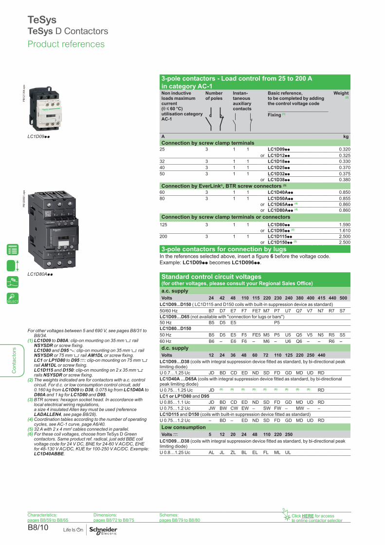
3-pole contactors - Load control from 25 to 200 A in category AC-1Non inductive loads maximum current (θ y 60 °C)utilisation category AC-1
Number of poles
Instan-taneous auxiliary contacts
Basic reference, to be completed by adding the control voltage code
Weight (2)
Fixing (1)
LC1D09pp A kgConnection by screw clamp terminals
25 3 1 1 LC1D09pp 0.320or LC1D12pp 0.325
32 3 1 1 LC1D18pp 0.33040 3 1 1 LC1D25pp 0.37050 3 1 1 LC1D32pp 0.375
or LC1D38pp 0.380
PB12
0691
.eps
Connection by EverLink®, BTR screw connectors (3)
60 3 1 1 LC1D40App 0.85080 3 1 1 LC1D50App 0.855
or LC1D65App (4) 0.860or LC1D80App (4) 0.860
Connection by screw clamp terminals or connectors125 3 1 1 LC1D80pp 1.590
or LC1D95pp (4) 1.610200 3 1 1 LC1D115pp 2.500
or LC1D150pp (5) 2.5003-pole contactors for connection by lugs
In the references selected above, insert a figure 6 before the voltage code.Example: LC1D09pp becomes LC1D096pp.
LC1D80App Standard control circuit voltages (for other voltages, please consult your Regional Sales Office)a.c. supplyVolts 24 42 48 110 115 220 230 240 380 400 415 440 500
LC1D09...D150 ( LC1D115 and D150 coils with built-in suppression device as standard)50/60 Hz B7 D7 E7 F7 FE7 M7 P7 U7 Q7 V7 N7 R7 S7LC1D09…D65 (not available with "connection for lugs or bars")50 Hz B5 D5 E5 P5LC1D80...D15050 Hz B5 D5 E5 F5 FE5 M5 P5 U5 Q5 V5 N5 R5 S560 Hz B6 – E6 F6 – M6 – U6 Q6 – – R6 –d.c. supplyVolts 12 24 36 48 60 72 110 125 220 250 440
LC1D09…D38 (coils with integral suppression device fitted as standard, by bi-directional peak limiting diode)U 0.7…1.25 Uc JD BD CD ED ND SD FD GD MD UD RDLC1D40A …D65A (coils with integral suppression device fitted as standard, by bi-directional peak limiting diode)U 0.75…1.25 Uc JD (6) (6) (6) (6) (6) (6) (6) (6) (6) RDLC1 or LP1D80 and D95U 0.85…1.1 Uc JD BD CD ED ND SD FD GD MD UD RDU 0.75…1.2 Uc JW BW CW EW – SW FW – MW – –LC1D115 and D150 (coils with built-in suppression device fitted as standard)U 0.75…1.2 Uc – BD – ED ND SD FD GD MD UD RDLow consumptionVolts c 5 12 20 24 48 110 220 250
LC1D09…D38 (coils with integral suppression device fitted as standard, by bi-directional peak limiting diode)U 0.8…1.25 Uc AL JL ZL BL EL FL ML UL
Product references
TeSysTeSys D Contactors
Characteristics: pages B8/59 to B8/65
Dimensions: pages B8/72 to B8/75
Schemes: pages B8/79 to B8/80
Click HERE for access to online contactor selector
For other voltages between 5 and 690 V, see pages B8/31 to B8/34.
(1) LC1D09 to D80A: clip-on mounting on 35 mm 5 rail NSYSDR or screw fixing.
LC1D80 and D95 a: clip-on mounting on 35 mm 5 rail NSYSDR or 75 mm 5 rail AM1DL or screw fixing.
LC1 or LP1D80 to D95 c: clip-on mounting on 75 mm 5 rail AM1DL or screw fixing.
LC1D115 and D150: clip-on mounting on 2 x 35 mm 5 rails NSYSDR or screw fixing.
(2) The weights indicated are for contactors with a.c. control circuit. For d.c. or low consumption control circuit, add 0.160 kg from LC1D09 to D38, 0.075 kg from LC1D40A to D80A and 1 kg for LC1D80 and D95.
(3) BTR screws: hexagon socket head. In accordance with local electrical wiring regulations, a size 4 insulated Allen key must be used (reference LADALLEN4, see page B8/28).
(4) Coordination tables according to the number of operating cycles, see AC-1 curve, page A6/40.
(5) 32 A with 2 x 4 mm2 cables connected in parallel.(6) For these coil voltages, choose from TeSys D Green
contactors. Same product ref. radical, just add BBE coil voltage code for 24 V DC, BNE for 24-60 V AC/DC, EHE for 48-130 V AC/DC, KUE for 100-250 V AC/DC. Exemple: LC1D40ABBE.
SELECT

B8/11
Con
tact
ors
3-pole contactors - Load control from 16 to 80 A in category AC-1Non inductive loads maximum current (θ y 60 °C)utilisation category AC-1
Number of poles
Instan-taneous auxiliary contacts
Basic reference, to be completed by adding the control voltage code
Weight (2)
Fixing (1)
A kgConnection by spring terminals
16 3 1 1 LC1D093pp (3) 0.320or LC1D123pp (3) 0.325
25 3 1 1 LC1D183pp (4) 0.335or LC1D253pp (5) 0.325or LC1D323pp (5) 0.325
Power connections by EverLink® BTR screw connectors (6) and control by spring terminals
60 3 1 1 LC1D40A3pp 0.85080 3 1 1 LC1D50A3pp (7) 0.855
or LC1D65A3pp (7) 0.860or LC1D80A3pp (7) 0.860
3-pole contactors for connection by Faston connectorsThese contactors are fitted with Faston connectors: 2 x 6.35 mm on the power poles and 1 x 6.35 mm on the coil terminals. For contactors LC1D09 and LC1D12 only, in the references selected from the previous page, insert a figure 9 before the voltage code. Example: LC1D09pp becomes LC1D099pp.Separate components
Auxiliary contact blocks and add-on modules: see pages B8/22 to B8/28.
Standard control circuit voltages (for other voltages, please consult your Regional Sales Office)a.c. supplyVolts 24 42 48 110 115 220 230 240 380 400 415 440 500
LC1D09...D80A50/60 Hz B7 D7 E7 F7 FE7 M7 P7 U7 Q7 V7 N7 R7 S7d.c. supplyVolts 12 24 36 48 60 72 110 125 220 250 440
LC1D09…D32 (coils with integral suppression device fitted as standard, by bi-directional peak limiting diode)U 0.7…1.25 Uc JD BD CD ED ND SD FD GD MD UD RDLC1D40A…D65A (coils with integral suppression device fitted as standard, by bi-directional peak limiting diode)U 0.75…1.25 Uc JD BD CD ED ND SD FD GD MD UD RDLow consumptionVolts c 5 12 20 24 48 110 220 250
LC1D09…D32 (coils with integral suppression device fitted as standard, by bi-directional peak limiting diode)U 0.8…1.25 Uc AL JL ZL BL EL FL ML ULFor other voltages between 5 and 690 V, see pages B8/31 to B8/34.(1) LC1D09 to D80A: clip-on mounting on 35 mm 5 rail NSYSDR or screw fixing.(2) The weights indicated are for contactors with a.c. control circuit. For d.c. or low consumption
control circuit, add 0.160 kg from LC1D09 to D38 and 0.075 kg from LC1D40A to D80A.(3) 20 A with 2 x 2.5 mm2 cables connected in parallel.(4) 32 A with 2 x 4 mm2 cables connected in parallel.(5) 40 A with 2 x 4 mm2 cables connected in parallel.(6) BTR screws: hexagon socket head. In accordance with local electrical wiring regulations,
a size 4 insulated Allen key must be used (reference LADALLEN4, see page B8/28).(7) Coordination tables according to the number of operating cycles, see AC-1 curve, page
A6/40.
Characteristics: pages B8/59 to B8/65
Dimensions: pages B8/72 to B8/75
Schemes: pages B8/79 to B8/80
Click HERE for access to online contactor selector
Product references
TeSysTeSys D Contactors
PB12
1355
.eps
LC1D123pp
PB12
0692
.eps
LC1D80A3pp
SELECT

B8/12
Con
tact
ors
PB12
1356
.eps 4-pole contactors - Load control, 20 to 200 A in category AC-1
Non inductive loads maximum current (θ y 60 °C)utilisation category AC-1
Number of poles
Instantaneous auxiliary contacts
Basic reference, to be completed by adding the control voltage code
Weight (2)
Fixing (1)
A kgConnection by screw clamp terminals
LC1DT20pp 20 4 – 1 1 LC1DT20pp 0.3652 2 1 1 LC1D098pp 0.365
25 4 – 1 1 LC1DT25pp 0.3652 2 1 1 LC1D128pp 0.365
32 4 – 1 1 LC1DT32pp 0.4252 2 1 1 LC1D188pp 0.425
40 4 – 1 1 LC1DT40pp 0.4252 2 1 1 LC1D258pp 0.425
PB12
1357
.eps Connection by EverLink®, BTR screw connectors
60 4 – 1 1 LC1DT60App 1.09080 4 – 1 1 LC1DT80App 1.150Connection by screw clamp terminals or connectors
60 2 2 – – LC1D40008pp 1.440or LP1D40008pp 2.210
80 2 2 – – LC1D65008pp 1.450or LP1D65008pp 2.220
125 4 – – – LC1D80004pp 1.760or LP1D80004pp 2.685
2 2 – – LC1D80008pp 1.840or LP1D80008pp 2.910
LC1DT80App 200 4 – – – LC1D115004pp 2.860
PB10
8321
.eps
LC1D65008pp
4-pole contactors for connection by lugs or barsIn the references selected above, insert a figure 6 before the voltage code. Example: LC1DT20pp becomes LC1DT206pp. Standard control circuit voltages (for other voltages, please consult your Regional Sales Office)a.c. supplyVolts 24 42 48 110 115 220 230 240 380 400 415 440 500
LC1D09...D150 and LC1DT20...DT80A (LC1D115 and D150 coils with built-in suppression device as standard)50/60 Hz B7 D7 E7 F7 FE7 M7 P7 U7 Q7 V7 N7 R7 –LC1D80...D11550 Hz B5 D5 E5 F5 FE5 M5 P5 U5 Q5 V5 N5 R5 S560 Hz B6 – E6 F6 – M6 – U6 Q6 – – R6 –d.c. supplyVolts 12 24 36 48 60 72 110 125 220 250 440
LC1D09…D25 and LC1DT20...DT40 (coils with integral suppression device fitted as standard, by bi-directional peak limiting diode)U 0.75…1.25 Uc JD BD CD ED ND SD FD GD MD UD RDLC1DT60A …DT80A (coils with integral suppression device fitted as standard, by bi-directional peak limiting diode)U 0.75…1.25 Uc JD (3) (3) (3) (3) (3) (3) (3) (3) (3) RDLP1D40...D80U 0.85…1.1 Uc JD BD CD ED ND SD FD GD MD UD RDU 0.75…1.2 Uc JW BW CW EW – SW FW – MW – –LC1D115 (coil with built-in suppression device as standard)U 0.75…1.2 Uc – BD – ED ND SD FD GD MD UD RDLow consumptionVolts c 5 12 20 24 48 110 220 250
LC1D09...D25 and LC1DT20...DT40 (coils with integral suppression device fitted as standard, by bi-directional peak limiting diode)U 0.8…1.25 Uc AL JL ZL BL EL FL ML ULFor other voltages between 5 and 690 V, see pages B8/31 to B8/34.(1) LC1D09 to D38 and LC1DT20 to DT80A: clip-on mounting on 35 mm 5 rail NSYSDR or screw fixing. LC1D80 a: clip-on mounting on 35 mm 5 rail NSYSDR or 75 mm 5 rail AM1DL or screw fixing. LC1 or LP1D80 c: clip-on mounting on 75 mm 5 rail AM1DL or screw fixing. LC1D115 and D150: clip-on mounting on 2 x 35 mm 5 rails NSYSDR or screw fixing.(2) The weights indicated are for contactors with a.c. control circuit. For d.c. or low consumption control circuit, add 0.160 kg from
LC1D09 to D38, 0.075 kg from LC1DT60A and D80A and 1 kg for LC1D80.(3) For these coil voltages, choose from TeSys D Green contactors. Same product ref. radical, just add BBE coil voltage code for
24 V DC, BNE for 24-60 V AC/DC, EHE for 48-130 V AC/DC, KUE for 100-250 V AC/DC. Exemple: LC1DT60ABBE.
Product references
TeSysTeSys D Contactors
Characteristics: pages B8/59 to B8/65
Dimensions: pages B8/72 to B8/75
Schemes: pages B8/79 to B8/80
Click HERE for access to online contactor selector
SELECT

B8/13
Con
tact
ors
4-pole contactors - Load control, 20 to 80 A in category AC-1Non inductive loads maximum current (θ y 60 °C)utilisation category AC-1
Number of poles
Instan-taneous auxiliary contacts
Basic reference, to be completed by adding the voltage code
Weight (2)
Fixing (1)
A kgConnection by spring terminals
20 4 – 1 1 LC1DT203pp 0.3802 2 1 1 LC1D0983pp 0.380
25 4 – 1 1 LC1DT253pp 0.3802 2 1 1 LC1D1283pp 0.380
32 4 – 1 1 LC1DT323pp 0.4252 2 1 1 LC1D1883pp 0.425
40 4 – 1 1 LC1DT403pp 0.4252 2 1 1 LC1D2583pp 0.425
Connection by EverLink®, BTR screw connectors and control circuit by spring terminals
60 4 – 1 1 LC1DT60A3pp 1.09080 4 – 1 1 LC1DT80A3pp 1.150
Separate componentsAuxiliary contact blocks and add-on modules: see pages B8/22 to B8/28.
Standard control circuit voltages (for other voltages, please consult your Regional Sales Office)a.c. supplyVolts 24 42 48 110 115 220 230 240 380 400 415 440 500
LC1D09...D25 and LC1DT20...DT80A (coils with integral suppression device fitted as standard, by bi-directional peak limiting diode)50/60 Hz B7 D7 E7 F7 FE7 M7 P7 U7 Q7 V7 N7 R7 –d.c. supplyVolts 12 24 36 48 60 72 110 125 220 250 440
LC1D09…D25 and LC1DT20... DT40 (coils with integral suppression device fitted as standard, by bi-directional peak limiting diode)U 0.7…1.25 Uc JD BD CD ED ND SD FD GD MD UD RDLC1DT60A...80A (coils with integral suppression device fitted as standard, by bi-directional peak limiting diode)U 0.75…1.25 Uc JD BD CD ED ND SD FD GD MD UD RDLow consumptionVolts c 5 12 20 24 48 110 220 250
LC1D09...D25 and LC1DT20...DT40 (coils with integral suppression device fitted as standard, by bi-directional peak limiting diode)U 0.8…1.25 Uc AL JL ZL BL EL FL ML ULFor other voltages between 5 and 690 V, see pages B8/31 to B8/34.(1) LC1D09 to D38 and LC1DT20 to DT80A: clip-on mounting on 35 mm 5 rail NSYSDR or
screw fixing.(2) The weights indicated are for contactors with a.c. control circuit. For d.c. or low consumption
control circuit, add 0.160 kg from LC1D09 to D38, 0.075 kg for LC1DT60A and DT80A.
Product references
TeSysTeSys D Contactors
Characteristics: pages B8/59 to B8/65
Dimensions: pages B8/72 to B8/75
Schemes: pages B8/79 to B8/80
Click HERE for access to online contactor selector
LC1DT253pp
PB10
8325
.eps
LC1DT80A3pp
PB10
8326
.eps
SELECT

B8/14
Con
tact
ors
PB12
1349
.eps Contactors conforming to UL and CSA standards (North American market ) -
25 to 160 AStandard power ratings of motors 50/60 Hz Associated cable
type 75 °C-CuUL continuous current
Type of contactor required Basic reference, to be completed
Single-phase 1 Ø
3-phase 3 Ø
120 V 240 V 208 V 240 V 480 V 600 V Fixing, connection (1)
HP HP HP HP HP HP ALC1D09pp Connection by screw clamp terminals
1/3 1 2 2 5 7.5 AWG 18 - 10 25 LC1D09pp
0.5 2 3 3 7.5 10 AWG 18 - 10 25 LC1D12pp
PB12
1350
.eps 1 3 5 5 10 15 AWG 18 - 8 32 LC1D18pp
2 3 7.5 7.5 15 20 AWG 14 - 6 40 LC1D25pp
2 5 10 10 20 25 AWG 14 - 6 50 LC1D32pp (2)
2 5 10 10 20 25 AWG 14 - 6 50 LC1D38pp (2)
Power connections by EverLink® BTR screw connectors and control by spring terminals3 5 10 10 30 30 AWG 16 - 2 60 LC1D40App
3 7.5 15 15 40 40 AWG 16 - 2 70 LC1D50App
5 10 20 20 40 50 AWG 16 - 2 80 LC1D65App
5 10 20 20 40 50 AWG 16 - 2 80 LC1D80App
LC1D25pp Connection by screw clamp terminals or connectors7.5 15 25 30 60 60 AWG 10 - 2 110 LC1D80pp
7.5 15 25 30 60 60 AWG 10 - 2 110 LC1D95pp
– – 30 40 75 100 AWG 8-1/0 160 LC1D115pp
– – 40 50 100 125 AWG 8-1/0 160 LC1D150pp
PB12
0609
.eps
Applications with High-Fault Short-Circuit ratingsHigh-fault short-circuit current ratings are: 100 kA (D09-80, D115-150) at 600 V with Class J fuses and 85 kA (D09-38), 100 kA (D40A-80, D115-150) at 480 V and 50 kA (D09-80, D115-150) at 600 V with circuit breakers.Application example
For a 15 HP-230 V motorSelect a contactor type LC1D50A.Information: the contactor rating selected corresponds to “size 2”, the associated cable is type AWG3 75 °C-Cu.
Standard control circuit voltages (for other voltages, please consult your Regional Sales Office)a.c. supplyVolts 24 42 48 110 115 120 208 220 230 240 380 400 415 440 480 500
LC1D09…D150 (D115 and D150 coils with built-in suppression device as standard)50/60 Hz B7 D7 E7 F7 FE7 G7 (3) LE7 (3) M7 P7 U7 Q7 V7 N7 R7 T7 (3) S7LC1D09…D65 (not available with "connection for lugs or bars")50 Hz B5 D5 E5 P5LC1D80…D11550 Hz B5 D5 E5 F5 FE5 G5 – M5 P5 U5 Q5 V5 N5 R5 – S560 Hz B6 – E6 F6 – G6 L6 M6 – U6 Q6 – – R6 T6 –d.c. supplyVolts 12 24 36 48 60 72 110 125 220 250 440
LC1D09…D32 (coils with integral suppression device fitted as standard, by bi-directional peak limiting diode)U 0.7…1.25 Uc JD BD CD ED ND SD FD GD MD UD RDLC1D40A…D65A (coils with integral suppression device fitted as standard, by bi-directional peak limiting diode)U 0.75…1.25 Uc JD (4) (4) (4) (4) (4) (4) (4) (4) (4) RDLC1D80 and D95U 0.85…1.1 Uc JD BD CD ED ND SD FD GD MD UD RDU 0.75…1.2 Uc JW BW CW EW – SW FW – MW – –LC1D115 and D150 (coils with built-in suppression device as standard)U 0.75…1.2 Uc – BD – ED ND SD FD GD MD UD RDLow consumptionVolts c 5 12 20 24 48 72 110 220 250
LC1D09…D38 (coils with integral suppression device fitted as standard, by bi-directional peak limiting diode)U 0.8…1.25 Uc AL JL ZL BL EL SL FL ML UL(1) LC1D09 to D65A: clip-on mounting on 35 mm 6 rail NSYSDR or screw fixing.
LC1D80 and LC1D95: clip-on mounting on 35 mm 6 rail NSYSDR or 75 mm 6 rail AM1DL or screw fixing. LC1D115 and D150: clip-on mounting on 2 x 35 mm 6 rails NSYSDR or screw fixing.
(2) Versions with spring terminals LC1D323 and LC1D383 are not certified UL/CSA.(3) Contactors LC1D40A, 50A, 65A, 80A: for this coil voltage use is only on 60 Hz.(4) For these coil voltages, choose from TeSys D Green contactors. Same product ref. radical, just add BBE coil voltage code for
24 V DC, BNE for 24-60 V AC/DC, EHE for 48-130 V AC/DC, KUE for 100-250 V AC/DC. Exemple: LC1D40ABBE.
LC1D80App
PB12
1351
.eps
LC1D95pp
Product references
TeSysTeSys D Contactors
Characteristics: pages B8/59 to B8/65
Dimensions: pages B8/72 to B8/75
Schemes: pages B8/79 to B8/80
Click HERE for access to online contactor selector
SELECT

B8/15
Con
tact
ors
PB10
8301
.eps
LC2D12pp
3-pole reversing contactors - Motors up to 75 kW / 400 V in category AC-3Horizontally mounted - Pre-wired power connections.Standard power ratings of 3-phase motors 50-60 Hz in category AC-3(θ y 60 °C)
Rated opera-tional current in AC-3 440 Vup to
Instan- taneous auxiliary contactspercontactor
Contactors supplied with coilBasic reference, to be completed by adding the control voltage code
Weight (2)
Fixing (1)
220 V 230 V
380 V400 V
415 V 440 V 500 V 660 V 690 V
1000 V
kW kW kW kW kW kW kW A kg
PB10
8340
.eps
With mechanical interlock, without electrical interlocking, for connection by screw clamp terminals or connectors
2.2 4 4 4 5.5 5.5 – 9 1 1 LC2D09pp (3) 0.6873 5.5 5.5 5.5 7.5 7.5 – 12 1 1 LC2D12pp (3) 0.6974 7.5 9 9 10 10 – 18 1 1 LC2D18pp (3) 0.7075.5 11 11 11 15 15 – 25 1 1 LC2D25pp (3) 0.7877.5 15 15 15 18.5 18.5 – 32 1 1 LC2D32pp (3) 0.7979 18.5 18.5 18.5 18.5 18.5 – 38 1 1 LC2D38pp (3) 0.80711 18.5 22 22 22 30 – 40 1 1 LC2D40App 1.870
LC2D65App 15 22 25 30 30 33 – 50 1 1 LC2D50App 1.88018.5 30 37 37 37 37 – 65 1 1 LC2D65App 1.89022 37 45 45 55 45 – 80 1 1 LC2D80pp 3.20025 45 45 45 55 45 – 95 1 1 LC2D95pp 3.200
PB12
1358
.eps
LC2D1156pp
With mechanical interlock and electrical interlocking, for connection by screw clamp terminals or connectors30 55 59 59 75 80 65 115 1 1 LC2D115pp 6.35040 75 80 80 90 100 75 150 1 1 LC2D150pp 6.400Connection by lugs or bars
For reversing contactors LC2D09 to LC2D38, LC2D115 and LC2D150, in the references selected above, insert a figure 6 before the voltage code. Example: LC2D09pp becomes LC2D096pp.To build a 40 to 65 A reversing contactor, for connection by lugs, order 2 contactors LC1DppA6 and mechanical interlock LAD4CM (see page B8/29).
Component partsAuxiliary contact blocks and add-on modules: see pages B8/22 to B8/28. (1) LC2D09 to D65A: clip-on mounting on 35 mm 5 rail NSYSDR or screw fixing.
LC2D80 and D95: clip-on mounting on 35 mm 5 rail NSYSDR or 75 mm 5 rail AM1DL or screw fixing. LC2D115 and D150: clip-on mounting on 35 mm 5 rail NSYSDR or screw fixing.
Standard control circuit voltages (for other voltages, please consult your Regional Sales Office)a.c. supplyVolts 24 42 48 110 115 220 230 240 380 400 415 440 500
LC2D09…D150 (D115 and D150 coils with built-in suppression device as standard)50/60 Hz B7 D7 E7 F7 FE7 M7 P7 U7 Q7 V7 N7 R7 S7LC2D80…D11550 Hz B5 D5 E5 F5 FE5 M5 P5 U5 Q5 V5 N5 R5 S560 Hz B6 – E6 F6 – M6 – U6 Q6 – – R6 –d.c.supplyVolts 12 24 36 48 60 72 110 125 220 250 440
LC2D09…D38 (coils with integral suppression device fitted as standard, by bi-directional peak limiting diode)U 0.7…1.25 Uc JD BD CD ED ND SD FD GD MD UD RDLC2D40A…D65A (coils with integral suppression device fitted as standard, by bi-directional peak limiting diode)U 0.75…1.25 Uc JD BD CD ED ND SD FD GD MD UD RDLow consumptionVolts c 5 12 20 24 48 110 220 250
LC2D09...D38 (coils with integral suppression device fitted as standard, by bi-directional peak limiting diode)U 0.8…1.25 Uc AL JL ZL BL EL FL ML ULFor other voltages between 5 and 690 V, see pages B8/31 to B8/34.(2) The weights indicated are for contactors with a.c. control circuit. For d.c. or low consumption control circuit, add 0.330 kg for
LC2D09 to D38, 0.150 kg for LC1D40A to D65A.(3) For reversing contactors with electrical interlocking pre-wired at the factory, add suffix V to the references selected above.
Example: LC2D09P7 becomes LC2D09P7V.Note: when assembling a reversing contactor, it is good practice to incorporate a 50 ms time delay.
Product references
TeSysTeSys D Reversing contactors
Characteristics: pages B8/59 to B8/65
Dimensions: pages B8/81 and B8/82
Schemes: pages B8/83 and B8/84
SELECT

B8/16
Con
tact
ors
TeSysTeSys D Reversing contactors
Characteristics: pages B8/59 to B8/65
Dimensions: pages B8/81 and B8/82
Schemes: pages B8/83 and B8/84
PB10
8305
.eps 3-pole reversing contactors - Motors up to 15 kW / 400 V in category AC-3
Pre-wired power connections.Mechanical interlock without electrical interlocking.Standard power ratings of 3-phase motors 50-60 Hz in category AC-3(θ y 60 °C)
Rated opera-tional current in AC-3 440 Vup to
Instan-taneous auxiliary contactspercontactor
Contactors supplied with coilBasic reference, to be completed by adding the voltage code
Weight (2)
LC2D123pp
Fixing (1)
220 V 230 V
380 V400 V
415 V 440 V 500 V 660 V 690 V
kW kW kW kW kW kW A kgFor connection by spring terminals
2.2 4 4 4 5.5 5.5 9 1 1 LC2D093pp 0.6873 5.5 5.5 5.5 7.5 7.5 12 1 1 LC2D123pp 0.6974 7.5 9 9 10 10 18 1 1 LC2D183pp 0.7075.5 11 11 11 15 15 25 1 1 LC2D253pp 0.7877.5 15 15 15 18.5 18.5 32 (3) 1 1 LC2D323pp 0.797Power connection by EverLink®, BTR screw connectors (4) and control by spring terminals
11 18.5 22 22 22 30 40 1 1 LC2D40A3pp 1.87015 22 25 30 30 33 50 1 1 LC2D50A3pp 1.88018.5 30 37 37 37 37 65 1 1 LC2D65A3pp 1.890For connection by Faston connectors
All power connections are to be made by the customer.These contactors are fitted with Faston connectors: 2 x 6.35 mm on the power poles and 1 x 6.35 mm on the coil terminals.For reversing contactors LC2D09 and LC2D12 only, in the references selected above, replace the figure 3 before the voltage code with a figure 9.Example: LC2D093pp becomes LC2D099pp.Component parts
Auxiliary contact blocks and add-on modules: see pages B8/22 to B8/28.(1) LC2D09 to D32: clip-on mounting on 35 mm 5 rail NSYSDR or screw fixing.
Standard control circuit voltages (for other voltages, please consult your Regional Sales Office)a.c. supplyVolts 24 42 48 110 115 220 230 240 380 400 415 440 500
LC2D09…D65A50/60 Hz B7 D7 E7 F7 FE7 M7 P7 U7 Q7 V7 N7 R7 S7d.c. supplyVolts 12 24 36 48 60 72 110 125 220 250 440
LC2D09…D32 (coils with integral suppression device fitted as standard, by bi-directional peak limiting diode)U 0.7…1.25 Uc JD BD CD ED ND SD FD GD MD UD RDLC2D40A …D65A (coils with integral suppression device fitted as standard, by bi-directional peak limiting diode)U 0.75…1.25 Uc JD BD CD ED ND SD FD GD MD UD RDLow consumptionVolts c 5 12 20 24 48 110 220 250
LC2D09...D32 (coils with integral suppression device fitted as standard, by bi-directional peak limiting diode)U 0.8…1.25 Uc AL JL ZL BL EL FL ML ULFor other voltages between 5 and 690 V, see pages B8/31 to B8/34.(2) The weights indicated are for reversing contactors with a.c. control circuit. For d.c. or low consumption control circuit, add
0.330 kg for LC2D09 to D38, 0.150 kg for LC1D40A to D65A.(3) Must be wired with 2 x 4 mm2 cables in parallel on the upstream side. On the downstream side, outgoing terminal block
LAD331 may be used (Quickfit technology, see page B1/18).When wired with a single cable, the product is limited to 25 A (11 kW/400 V motors).
(4) BTR screws: hexagon socket head. In accordance with local electrical wiring regulations, a size 4 insulated Allen key must be used (reference LADALLEN4, see page B8/28).
Product references
Click HERE for access to online contactor selector
SELECT

B8/17
Con
tact
ors
Characteristics: pages B8/59 to B8/65
Dimensions: page B8/81
Schemes: pages B8/83 and B8/84
Product references
TeSysTeSys D Green Reversing contactors
TeSys D Green contactors have a dark grey casing and a 3-character code voltage.
DB4
2487
4.ep
s 3-pole reversing contactors - Motors up to 37 kW / 400 V in category AC-3Pre-wired power connectionsStandard power ratings of 3-phase motors 50-60 Hz in category AC-3(θ y 60 °C)
Rated opera-tional current in AC-3 440 Vup to
Instan- taneous auxiliary contactspercontactor
Contactors supplied with coilPartial reference, to be completed by adding the control voltage code
Weight
Fixing (1)
220 V 230 V
380 V400 V
415 V 440 V 500 V 660 V 690 V
kW kW kW kW kW kW A kg
DB4
2487
0.ep
s With mechanical interlock, without electrical interlocking, for connection by screw clamp terminals or Everlink BTR screw connectors (2) (3)
2.2 4 4 4 5.5 5.5 9 1 1 LC2D09ppp 0.7833 5.5 5.5 5.5 7.5 7.5 12 1 1 LC2D12ppp 0.7934 7.5 9 9 10 10 18 1 1 LC2D18ppp 0.8035.5 11 11 11 15 15 25 1 1 LC2D25ppp 0.9137.5 15 15 15 18.5 18.5 32 1 1 LC2D32ppp 0.9239 18.5 18.5 18.5 18.5 18.5 38 1 1 LC2D38ppp 0.93311 18.5 22 22 22 30 40 1 1 LC2D40Appp (2) 2.15415 22 25 30 30 33 50 1 1 LC2D50Appp (2) 2.16418.5 30 37 37 37 37 65 1 1 LC2D65Appp (2) 2.17422 37 37 37 37 37 66 1 1 LC2D80Appp (2) 2.174
Auxiliary contact blocks and add-on modulesSee pages B8/22 to B8/28.
Coil voltage codesAC/DC 24 V DC supplyVolts 24 (DC only) 24-60 48-130 100-250
LC2D09...D32, LC2D40A ... D80AU 0.85...1.1 Uc BNE EHE KUELC2D09...D38U 0.8...1.2 Uc BNELC2D40A ...D80AU 0.8...1.2 Uc BBE(1) LC2D09 to D80A: clip-on mounting on 35 mm 5 rail NSYSDR or screw fixing.(2) BTR screws: hexagon socket head. In accordance with local electrical wiring regulations, a size 4 insulated Allen key must be
used (reference LADALLEN4, see page B8/28).(3) Electrical interlocking is recommended when 2 orders (direct and reverse) could appeared in the same time.
LC2D09ppp
LC2D40Appp
Click HERE for access to online contactor selector
SELECT

B8/18
Con
tact
ors
PB10
8324
.eps 4-pole changeover contactor pairs - 20 to 200 A in category A-1
Pre-assembled. Pre-wired power connections LC2DT20 to LC2DT40: mechanical interlock without electrical interlocking. LC2D80004: order separately 2 auxiliary contact blocks LADNp1 to obtain electrical interlocking between the 2 contactors (see page B8/22). For electrical interlocking incorporated in the mechanical interlock, please consult your Regional Sales Office.LC2D115004: mechanical interlock with integral, pre-wired electrical interlocking.
LC2DT20pp For connection by screw clamp terminals or connectorsUtilisation category AC-1Non-inductive loadsMaximum rated operational current(θ y 60 °C)
Instantaneous auxiliary contacts per contactor
Contactors supplied with coil
Weight
Basic reference, to be completed by adding the voltage code (1)
Fixing (2)
A kg
PB12
1359
.eps 20 1 1 LC2DT20pp 0.730
25 1 1 LC2DT25pp 0.730
32 1 1 LC2DT32pp 0.850
40 1 1 LC2DT40pp 0.850
125 – – LC2D80004pp 3.200
LC2D115004pp 200 – – LC2D115004pp 7.400
For connection by lugs or bars20 1 1 LC2DT206pp 0.730
25 1 1 LC2DT256pp 0.730
32 1 1 LC2DT326pp 0.850
40 1 1 LC2DT406pp 0.850
For customer assemblyFor connection by screw clamp terminals or connectors
60 1 1 LC1DT60App (3) –
80 1 1 LC1DT80App (3) –
For connection by lugs or bars60 1 1 LC1DT60A6pp (3) –
80 1 1 LC1DT80A6pp (3) –
Auxiliary contact blocks and add-on modules: see pages B8/22 to B8/28.
Note: when assembling changeover contactor pairs, it is good practice to incorporate a 50 ms time delay.
(1) See note (1) on next page.(2) LC2DT20 to LC2DT80: clip-on mounting on 35 mm 5 rail NSYSDR or screw fixing.
LC2D80: clip-on mounting on 35 mm 5 rail NSYSDR or 75 mm 5 rail AM1DL or screw fixing. LC2D115: clip-on mounting on 2 x 35 mm 5 rails NSYSDR or screw fixing.
(3) For these operational currents, order 2 identical contactors and a mechanical interlock LAD4CM (see page B8/29).
Product references
TeSysTeSys D Changeover contactors
Characteristics: pages B8/59 to B8/65
Dimensions: pages B8/81 and B8/82
Schemes: pages B8/83 and B8/84
Click HERE for access to online contactor selector
SELECT

B8/19
Con
tact
ors
TeSysTeSys D Changeover contactorsProduct references
Characteristics: pages B8/59 to B8/65
Dimensions: pages B8/81 and B8/82
Schemes: pages B8/83 and B8/84
4-pole changeover contactor pairs for 20 to 80 A control in category AC-1Pre-assembled, for customer assemblyPre-wired power connections, for connection by spring terminals.Utilisation category AC-1Non-inductive loadsMaximum rated operational current(θ y 60 °C)
Instantaneous auxiliary contacts per contactor
Contactors supplied with coilBasic reference, to be completed by adding the control voltage codeFixing (1)
A20 1 1 LC2DT203pp
Power connection by EverLink®, BTR screw connectors (2) and control by spring terminals
60 1 1 LC1DT60A3pp (3)
80 1 1 LC1DT80A3pp (3)
Separate componentsAuxiliary contact blocks and add-on modules: see pages B8/19 to B8/19. Standard control circuit voltages (for other voltages, please consult your Regional Sales Office)a.c. supplyVolts 24 42 48 110 115 220 230 240 380 400 415 440 500
LC2DT20…DT40, LC2DT60A…DT80A50/60 Hz B7 D7 E7 F7 FE7 M7 P7 U7 Q7 V7 N7 R7 –LC2D80004…D11500450 Hz B5 D5 E5 F5 FE5 M5 P5 U5 Q5 V5 N5 R5 S560 Hz B6 – E6 F6 – M6 – U6 Q6 – – R6 –d.c. supplyVolts 12 24 36 48 60 72 110 125 220 250 440
LC2DT20…DT40, LC1DT60…DT80 (coils with integral suppression device fitted as standard, by bi-directional peak limiting diode)U 0.7…1.25 Uc JD BD CD ED ND SD FD GD MD UD RDLow consumptionVolts c 5 12 20 24 48 110 220 250
LC2DT20...DT40 (coils with integral suppression device fitted as standard, by bi-directional peak limiting diode)U 0.8…1.25 Uc AL JL ZL BL EL FL ML ULFor other voltages between 5 and 690 V, see pages B8/19 to B8/19.(1) Clip-on mounting on 35 mm 5 rail NSYSDR or screw fixing.(2) BTR screws: hexagon socket head. In accordance with local electrical wiring regulations,
a size 4 insulated Allen key must be used (reference LADALLEN4, see page B8/19).(3) For these operational currents, order 2 identical contactors and a mechanical interlock
LAD4CM (see page B8/19).
Example of necessary components for customer assembly: 2 x LC1DT80A3pp contactors + LAD4CM mechanical interlock
+ +
Click HERE for access to online contactor selector
SELECT

B8/20
Con
tact
ors
TeSysTeSys D Contactors for switching capacitors banks
Contactors for switching 3-phase capacitor banks (power factor correction)Special contactors LC1DpK are designed for switching 3-phase, single or multiple-step capacitor banks (up to 6 steps). Over 6 steps, it is recommanded to use chokes in order to limit the inrush current and thus improve the lifetime of the installation. The contactors are conform to standards IEC 60070 and 60831, UL and CSA.
Contactor applications Specification Contactors fitted with a block of early make poles and damping resistors, limiting the value of the current on closing to 60 In max.This current limitation increases the life of all the components of the installation, in particular that of the fuses and capacitors.
Operating conditionsShort-circuit protection must be provided by gI type fuses rated at 1.7…2 In. It will ensure the service continuity of the whole installation in case of a capacitor contactor end of life
Maximum operational power
The power values given in the selection table below are for the following operating conditions:
Prospective peak current at switch-on
LC1DpK 200 In
Maximum operating rate LC1DFK, DGK, DLK, DMK 240 operating cycles/hourLC1DPK, DTK, DWK 100 operating cycles/hour
Electrical durability at nominal load
All contactor ratings 400 V 300 000 operating cycles690 V 200 000 operating cycles
Operational power at 50/60 Hz (1) θ y 60 °C (2)
Instantaneous auxiliary contacts
Tightening torque on cable end
Basic reference, to be completed by adding the voltage code (3)
Weight
230 V 400 V 440 V 690 V415 V
kVAR kVAR kVAR kVAR N/O N/C N.m kg7 12.5 12.5 21 1 2 1.7 LC1DFKpp 0.430
9.5 16.7 16.7 28.5 1 2 2.5 LC1DGKpp 0.450
11 20 21 33 1 2 2.5 LC1DLKpp 0.600
14 25 27 42 1 2 2.5 LC1DMKpp 0.630
17 30 32 50 1 2 5 LC1DPKpp 1.300
22 40 43 67 1 2 5 LC1DTKpp 1.300
35 63 67 104 1 2 9 LC1DWK12pp 1.650
Switching of multiple-step capacitor banks (with equal or different power ratings)The correct contactor for each step is selected from the above table, according to the power rating of the step to be switched.Example: 50 kVAR 3-step capacitor bank. Temperature: 50 °C and U = 400 V or 440 V.One 25 kVAR step: contactor LC1DMK, one 15 kVAR step: contactor LC1DGK, and one 10 kVAR step: contactor LC1DFK.(1) Operational power of the contactor according to the scheme on the page opposite.(2) The average temperature over a 24-hour period, in accordance with standards IEC 60070 and
60831 is 45 °C.(3) Standard control circuit voltages (the delivery time is variable, please consult your Regional Sales
Office):
Volts 24 48 110 120 220 230 240 380 400 415 44050/60 Hz B7 E7 F7 G7 M7 P7 U7 Q7 V7 N7 R7
Product references
Dimensions, schemes:page B8/85
LC1DFKpp
PB11
5163
.eps
LC1DGKpp, LC1DLKpp, LC1DMKpp
PB11
5164
.eps
LC1DPKpp, LC1DTKpp
PB11
5167
.eps
LC1DWK12pp
PB11
5169
.eps
Click HERE for access to online contactor selector
SELECT

B8/21
Con
tact
ors
DB4
2548
5.ep
s
See page opposite for mounting possibilities according to the contactor type
(1)
or
(1) No left side mounting on TeSys D Green contactors.
B8/22
Con
tact
ors
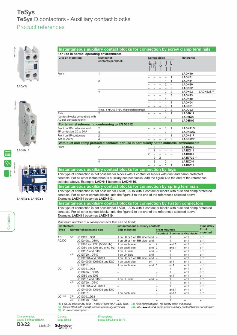
Instantaneous auxiliary contact blocks for connection by screw clamp terminalsFor use in normal operating environmentsClip-on mounting Number of
contacts per blockComposition Reference
Front 1 – – – 1 – LADN10– – – – 1 LADN01
2 – – – 1 1 LADN11– – – 2 – LADN20– – – – 2 LADN02
4 – – – 2 2 LADN22 LADN22S (4)
– – – 1 3 LADN13– – – 4 – LADN40– – – – 4 LADN04– – – 3 1 LADN31
4 incl. 1 N/O & 1 N/C make before break – – – 2 2 LADC22Side (contact blocks compatible with AC coil contactors only)
2 – – – 1 1 LAD8N11– – – 2 – LAD8N20– – – – 2 LAD8N02
For terminal referencing conforming to EN 50012Front on 3P contactors and 4P contactors 20 to 80 A
2 – – – 1 1 LADN11G4 – – – 2 2 LADN22G
Front on 4P contactors125 to 200 A
2 – – – 1 1 LADN11P4 – – – 2 2 LADN22P
With dust and damp protected contacts, for use in particularly harsh industrial environmentsFront 2 – 2 – – – LA1DX20
1 1 – – – LA1DX112 – – – – LA1DX02– 2 2 – – LA1DY20 (2)
4 – 2 – 2 – LA1DZ40– 2 – 1 1 LA1DZ31
Instantaneous auxiliary contact blocks for connection by lugsThis type of connection is not possible for blocks with 1 contact or blocks with dust and damp protected contacts. For all other instantaneous auxiliary contact blocks, add the figure 6 to the end of the references selected above. Example: LADN11 becomes LADN116.Instantaneous auxiliary contact blocks for connection by spring terminals
This type of connection is not possible for LAD8, LADN with 1 contact or blocks with dust and damp protected contacts. For all other contact blocks, add the figure 3 to the end of the references selected above. Example: LADN11 becomes LADN113.Instantaneous auxiliary contact blocks for connection by Faston connectors
This type of connection is not possible for LAD8, LADN with 1 contact or blocks with dust and damp protected contacts. For all other contact blocks, add the figure 9 to the end of the references selected above. Example: LADN11 becomes LADN119.
Maximum number of auxiliary contacts that can be fitted:Contactors Instantaneous auxiliary contacts Time delay
Front mounted
Type Number of poles and size Side mounted Front mounted1 contact 2 contacts 4 contacts
ACAC/DC
3P LC1D09…D38 1 on LH or 1 on RH side(1) and – 1 or 1 or 1LC1D40A…D80A 1 on LH or 1 on RH side and – 1 or 1 or 1LC1D80 and D95 (50/60 Hz) 1 on each side or 2 and 1 or 1 or 1LC1D80 and D95 (50 or 60 Hz) 1 on each side and 2 and 1 or 1 or 1LC1D115 and D150 1 on LH side and – 1 or 1 or 1
4P LC1DT20…DT40 1 on LH side and – 1 or 1 or 1LC1DT60A and DT80A 1 on LH or 1 on RH side and – 1 or 1 or 1LC1D40008, D65008 and D80 1 on each side or 1 or 1 or 1 or 1LC1D115 1 on each side and 1 or 1 or 1 or 1
DC 3P LC1D09…D38 – – 1 or 1 or 1LC1D40A…D80A – – 1 or 1 or 1LC1D80 and D95 – 1 or 1 or 1 or 1LC1D115 and D150 1 on LH side and – 1 or 1 or 1
4P LC1DT20…DT40 – – 1 or 1 or 1LC1DT60A and DT80A – – 1 or 1 or 1LC1D40008, D65008 and D80 – 2 and 1 or 1 or 1LC1D115 1 on each side – and 1 or 1 or 1
LC (3) (5) 3P LC1D09…D38 – – 1 – –4P LC1DT20…DT40 – – 1 – –
(1) 1 on LH side for AC coils - 1 on RH side for AC/DC coils.(2) Device fitted with 4 earth screen continuity terminals.(3) LC: low consumption.
(4) With red front face - for safety chain indication. (5) LA1Dppp dust & damp proof auxiliary contact blocks not allowed.
Product references
TeSysTeSys D contactors - Auxilliary contact blocks
LADN11
PB12
1389
.eps
LAD8N11
PB12
1388
.eps
LA1DXpp, LA1DZpp
PB12
1544
.eps
Characteristics: pages B8/66 and B8/67
Curves: page B8/68
Dimensions: pages B8/72 and B8/73

B8/23
Con
tact
ors
PB10
8336
.eps
DF5
3778
3.ep
s
Time delay auxiliary contact blocks for connection by screw clamp terminals
Maximum number of auxiliary contact blocks that can be fitted per contactor, see page B8/22.Sealing cover to be ordered separately, see page B8/28.LADT0 and LADR0: with extended scale from 0.1 to 0.6 s.LADS2: with switching time of 40 ms ± 15 ms between opening of the N/C contact and closing of the N/O contact.
LADTp Clip-on mounting Number of contacts
Time delay ReferenceType Setting range
Front 1 N/O + 1 N/C On-delay 0…3 s LADT01…30 s LADT210…180 s LADT41…30 s LADS2
Off-delay 0…3 s LADR01…30 s LADR210…180 s LADR4
PB10
8336
.eps
DF5
3778
5.ep
s
Time delay auxiliary contact blocks for connection by lugsAdd the figure 6 to the end of the references selected above. Example: LADT0 becomes LADT06.Time delay auxiliary contact blocks for connection by spring terminals
Add the figure 3 to the end of the references selected above. Example: LADT0 becomes LADT03.
LADTp3 Time delay auxiliary contact blocks for connection by Faston connectors
Add the figure 9 to the end of the references selected above. Example: LADT0 becomes LADT09.
PB12
1545
.eps
LAD6K10p
DF5
3778
4.ep
s
Mechanical latch blocks (1)
Clip-on mounting
Unlatching control
For use on contactor
Basic reference, to be completed by adding the control voltage code (2)
Front Manual or electric
LC1D09…D38 (a or c) (3)
LC1DT20…DT40 (a or c)LAD6K10p
LC1D40A…D80A (3 P a or c)LC1DT60A and DT80A(4 P a or c)
LA6DK10p
LC1D80…D150 (3 P a)LC1D80 and D115 (3 P c)LC1D80 (4 P a)LC1D80 and D115 (4 P a)LP1D80 and LC1D115 (4 P c)
LA6DK20p
(1) The mechanical latch block must not be powered up at the same time as the contactor. The duration of the control signal for the mechanical latch block and the contactor should be: u 100 ms for a contactor operating on an a.c. supply, u 250 ms for a contactor operating on a d.c. supply. Maximum impulse duration for the LAD6K10p mechanical latch block: 10 seconds.
(2) Standard control circuit voltages (for other voltages, please consult your Regional Sales Office):
Volts 50/60 Hz, c
24 32/36 42/48 60/72 100 110/127 220/240 256/277 380/415
Code B C E EN K F M U Q(3) The DC, low consumption contactors ( coil code pL) are not compatible with the mechanical
latch blocks LAD6K10p.
Product references
Characteristics:pages B8/66 to B8/68
Dimensions:pages B8/72 to B8/75
Schemes: pages B8/79 to B8/80
TeSysTeSys D contactors - Time delay auxilliary contact blocks

B8/24
Con
tact
ors
PB12
1400
.eps
DF5
3778
7.ep
s
RC circuits (Resistor-Capacitor)Effective protection for circuits highly sensitive to "high frequency" interference. For use only in cases where the voltage is virtually sinusoidal. i.e. less than 5 % total harmonic distortion. Voltage limited to 3 Uc max. and oscillating frequency limited to 400 Hz max. Slight increase in drop-out time (1.2 to 2 times the normal time).Mounting For use with contactor (1) Reference
Rating TypeV a V c
LAD4RCU LAD4pp Clip-on side mounting (3) (5) D09…D38 (3P)DT20…DT40
24…48 – LAD4RCE50…127 – LAD4RCG110…250 – LAD4RCU
PB12
1546
.eps
DF5
3778
8.ep
s
Clip-on front mounting (3) (5) D40A…D65A (3P)DT60A…DT80A (4P)
24…48 – LAD4RC3E50…127 – LAD4RC3G110…240 – LAD4RC3U380…415 – LAD4RC3N
Screw fixing (4) D80…D150 (3P)D40…D115 (4P)
24…48 – LA4DA2E50…127 – LA4DA2G110…240 – LA4DA2U380…415 – LA4DA2N
Varistors (peak limiting)Protection provided by limiting the transient voltage to 2 Uc max. Maximum reduction of transient voltage peaks. Slight increase in drop-out time (1.1 to 1.5 times the normal time).Clip-on side mounting (3) (5) D09…D38 (3P)
DT20…DT4024…48 – LAD4VE50…127 – LAD4VG110…250 – LAD4VU
Clip-on front mounting (3) (5) D40A…D65A (3P)DT60A…DT80A (4P)
24…48 24…48 LAD4V3E50…127 50…127 LAD4V3G110…250 110…250 LAD4V3U
Screw fixing (4) D80…D115 (3P) D80…D115 (4P)
24…48 – LA4DE2E50…127 – LA4DE2G110…250 – LA4DE2U
D80…D95 (3P)D80 (4P)
– 24…48 LA4DE3E– 50…127 LA4DE3G– 110…250 LA4DE3U
LAD4RC3p, LAD4V3p,LAD4D3U, LAD4T3p
PB12
1547
.eps
DF5
3778
9.ep
s
LA4Dpp
Flywheel diodesNo overvoltage or oscillating frequency. Increase in drop-out time (6 to 10 times the normal time). Polarised component.Clip-on side mounting (5) D09…D38 (3P), DT20…DT40 – 5...600 LAD4DDLClip-on front mounting (5) D40A…D65A (3P), DT60A…DT80A (4P) – 24…250 LAD4D3UScrew fixing (4) D80 and D95 (3P), D40…D80 (4P) – 24…250 LA4DC3U
Bidirectional peak limiting diodesProtection provided by limiting the transient voltage to 2 Uc max. Maximum reduction of transient voltage peaks.Clip-on side mounting (3) D09…D38 (3P)
DT20…DT40 (4P) (2)24 – LAD4TB– 24 LAD4TBDL72 – LAD4TS– 72 LAD4TSDL– 125 LAD4TGDL– 250 LAD4TUDL– 600 LAD4TXDL
Clip-on front mounting (3) D40A…D65A (3P)DT60A…DT80A (4P) (2)
12…24 12…24 LAD4T3B25…72 25…72 LAD4T3S73…125 73…125 LAD4T3G126…250 126…250 LAD4T3U251…440 251…440 LAD4T3R
Screw fixing (4) D80…D95 (3P)D40…D80 (4P)
12…24 – LA4DB2B25…72 – LA4DB2S– 24 LA4DB3B– 72 LA4DB3S
(1) For satisfactory protection, a suppressor module must be fitted across the coil of each contactor except for TeSys D Green (ppE coil), as surge protection is already embedded.
(2) From D09 to D65A and from LC1DT20 to DT80A, d.c, low consumption are fitted with a built-in bidirectional peak limiting diode suppressor as standard. This bidirectional peak limiting diode is removable and can therefore be replaced by the user. (See reference above). If a d.c. or low consumption contactor is used without suppression, the standard suppressor should be replaced with a blanking plug (reference LAD9DL for LC1D09 to D38 and LC1DT20 to DT40; reference LAD9DL3 for LC1D40A to D65A and LC1DT60A to DT80A).
(3) Clipping-on makes the electrical connection. The overall size of the contactor remains unchanged.(4) Mounting at the top of the contactor on coil terminals A1 and A2.(5) In order to install these accessories, the existing suppression device must first be removed.
DF5
3779
0.ep
s
LAD4DDL or LAD4TpDL
TeSysTeSys D contactors - Suppressor modulesProduct references
PB12
1401
.eps
LAD4DDL
Characteristics: page B8/69

B8/25
Con
tact
ors
(1)
(1)
See page opposite for mounting possibilities according to the contactor type.
DB4
2548
6.ep
s
(1) For TeSys D with AC coil only.

B8/26
Con
tact
ors
Electronic serial timer modules (1)
b 3-pole contactors LC1D09 to D38: mounted using adapter LAD4BB, to be ordered separately, see below.
b 3-pole contactors LC1D40A to D65A: mounted using adapter LAD4BB3, to be ordered separately, see below.
b 3-pole contactors LC1D80 to D150 and 4-pole contactors LC1D40 to D115: mounted directly across terminals A1 and A2 of the contactor.On-delay typeOperational voltage a Time delay Reference24…250 V 100…250 V
LC1D09…D80A (3P) LC1D80…D150 (3P) 0.1…2 s LA4DT0U1.5…30 s LA4DT2U25…500 s LA4DT4U
Interface modules b 3-pole contactors LC1D09 to D38: mounted using adapter LAD4BB,
to be ordered separately, see below. b 3-pole contactors LC1D40A to D80A: mounted using adapter LAD4BB3,
to be ordered separately, see below.Relay interfaceOperational voltage a Supply
voltage E1-E2 (c)Reference
24…250 VLC1D09…D150 (3P) 24 V LA4DFBStatic relay interfaceOperational voltage a Supply
voltage E1-E2 (c)
Reference24…250 V 100…250 V
LC1D09…D80A (3P) LC1D80…D115 (3P) 24 V LA4DWB
Adapter kit for low control signalFor use on contactors
Composition Reference
LC1D40A…D80A (3P) (2)
b 1 LAD4BB3 coil wiring adapter b 1 LA4DFB relay interface module
LA4DBL
Wiring adapters for coil retrofit of 3 pole contactorsFor adapting existing wiring to a new productFor use on contactors
Reference
LC1D09…D38 Without coil suppression LAD4BB (3)
With coil suppression a 24…48 V LAD4BBVEa 50…127 V LAD4BBVGa 110…250 V LAD4BBVU
LC1D40A…80A Without coil suppression LAD4BB3(1) For 24 V operation, the contactor must be fitted with a 21 V coil (code Z).
See pages B8/31 to B8/34.(2) The kit is compatible with a coil voltage of a 24 V to a 250 V (B7 to U7)
and c 24 V to c 250 V (BD to UD).(3) LAD4BB can not be used with 4 poles contactors.
Product references
Characteristics:page B8/70
Dimensions:page B8/72
Schemes: page B8/80
TeSysTeSys D contactors - Accessories
LA4DTpp
PB12
1548
.eps
LA4DFB
PB12
1549
.eps
LA4DBL
PB12
1550
.eps
LAD4BBVU
PB12
1402
.eps

B8/27
Con
tact
ors
PB12
1360
.eps Accessories for main pole and control connections
Description For use with contactors LC1 Sold in lots of
Unit referencea c
Connectors for cable, size (1 connector)
4-pole 10 mm2 DT20, DT25 DT20, DT25 1 LAD92560
LA9D3260 3-pole 25 mm2 D09…D38 D09…D38 1 LA9D3260
PB12
1361
.eps
LA9D11550p
EverLink®
terminal block3-pole D40A…D80A D40A…D80A 1 LAD96560
Connectors for cables (2 connectors)
3-pole 120 mm2 D115, D150 D115, D150 1 LA9D1156034-pole 120 mm2 D115 D115 1 LA9D115604
PB12
1362
.eps Connectors for
lug type terminals (2 connectors)
3-pole D1156, D1506 D1156, D1506 1 LA9D1155034-pole D1156 D1156 1 LA9D115504
Protective coversfor connectors for lug type terminals
3-pole D40A6…D80A6 D40A6…D80A6 1 LAD96570
LAD96570 D1156, D1506 D1156, D1506 1 LA9D115703 (1)
PB12
1363
.eps
4-pole D60A6…D80A6 D60A6…D80A6 1 LAD96580D1156, D1506 D1156, D1506 1 LA9D115704
IP 20 covers for lug type terminals (for mounting with circuit breakers GV3 Ppp6 and GV3 Lpp6)
3 poles D40A6…D80A6 D40A6…D80A6 1 LAD96575
Links for parallel connection of
2 poles D09…D38 D09…D38 10 LA9D2561LA9D11560p DT20, DT25 (4P) DT20, DT25 (4P) 10 LA9D1261
PB12
1364
.eps DT32, DT40 (4P) DT32, DT40 (4P) 10 LAD96061
D40A…D80A D40A…D80A 1 LAD9P32D80, D95 D80, D95 2 LA9D80961
3 poles D09…D38 D09…D38 10 LAD9P3 (2)
LA9D11570p D40A…D80A D40A…D80A 1 LAD9P33
PB12
1365
.eps D80, D95 D80, D95 1 LA9D80962
4 poles DT20, DT25 DT20, DT25 2 LA9D1263
D80 D80 2 LA9D80963
LA9D80962 Staggered coil connection – D80 10 LA9D09966
PB12
1366
.eps Control circuit take-off
from main poleD80, D95 D80, D95 10 LA9D8067D115, D150 D115, D150 10 LA9D11567
LA9D11567 Spreaders for increasing the pole pitch to 45 mm
D115, D150 D115, D150 3 GV7AC03
(1) For 3-pole contactors: 1 set of 6 covers, for 4-pole contactors: 1 set of 8 covers.(2) Separate connecting bar for connecting 2 poles in parallel.
Product references
TeSysTeSys D contactors - Accessories
> Click on QR code to download
Control Panel Technical Guide:Mounting and wiring accessories for TeSys D, K, F - Star Delta, reverser, low-high speed control motor starters and changeover applications - Product references and details on all kits and wiring accessories.
> Ref. Document: CPTG011_EN

B8/28
Con
tact
ors
Sets of contacts and arc chambersDescription For contactor Reference
Sets of contacts 3-pole LC1D115 LA5D1158031LC1D150 LA5D150803
4-pole LC1D115004 LA5D115804Arc chambers 3-pole LC1D115 LA5D11550
LC1D150 LA5D150504-pole LC1D115004 LA5D115450
PB12
1367
.eps
Power connection accessoriesTerminal block For supply to one or more GV2G busbar sets GV1G09Set of 63 A busbars for parallelling of contactors
2 contactors LC1D09…D18 or D25…D38 GV2G2454 contactors LC1D09…D18 or D25…D38 GV2G445
Set of 115 A busbars for parallelling of contactors
2 contactors LC1D40A…D80A GV3G2643 contactors LC1D40A…D80A GV3G364 (1)
Set of S-shape busbars For circuit breakers GV3Ppp and GV3Lpp (3) and contactors LC1D40A…D73A
GV3S
GV2G245
PB12
1368
.eps
PB12
1369
.eps
GV1G09 GV3S
PB12
1370
.eps
Protection accessoriesDescription Use Sold in
lots ofReference
Miniature control circuit fuse holder
5 x 20 with 4 A-250 V fuse 1 LA9D941
Sealing cover For LADT, LADR 1 LA9D901Safety cover preventing access to the moving contact carrier
LC1D09…D80A and DT20…DT80A 1 LAD9ET1Red cover (for safety chain indication) 1 LAD9ET1SLC1D80 and D95 1 LAD9ET3Red cover (for safety chain indication) 1 LAD9ET3SLC1D115 and D150 1 LAD9ET4Red cover (for safety chain indication) 1 LAD9ET4S
LA9D941
PB12
1371
.eps
LAD9ET1
PB11
3924
.eps Marking accessories
Description Use Sold in lots of
Unit reference
Sheet of 64 blank legends, self-adhesive, 8 x 33 mm (2)
Contactors (except 4P) LC1D80…D115, LADN (4 contacts), LA6DK
10 LAD21
Sheet of 112 blank legends, self-adhesive, 8 x 12 mm (2)
LADN (2 contacts), LADT, LADR, LRD
10 LAD22
Sheet of 64 blank legends for marking using plotter or 8 x 33 mm engraver
Contactors (except 4P) LC1D80…D115, LAD (4 contacts), LA6DK
10 LAD23
Sheet of 440 blank legends for marking using plotter or 8 x 12 mm engraver
All products 35 LAD24
Marker holder snap-in, 8 x 22 mm
4-pole contactors, LC1D80...D115, LA6DK
100 LA9D92
Marker holder snap-in, 8 x 18 mm
LC1D09...D65A, LC1DT20...DT80A,LADN (4 contacts), LADT, LADR
100 LAD90
Bag of 300 blank legends self-adhesive, 7 x 21 mm
On holder LA9D92 1 LA9D93
LAD9ET1S
PB12
1372
.eps
LAD21...24
PB12
1373
.eps
LAD90
PB12
1374
.eps
Mounting accessoriesRetrofit plate for screw fixing
For replacement of LC1D40 to D80 with LC1D40A to D80A
1 LAD7X3
Mounting plate For replacement of LC1F115 or F150 with LC1D115 or D150
1 LA9D730
Size 4 Allen key, insulated, 1000 V
For use on contactors LC1D40A to LC1D150
5 LADALLEN4
(1) With this set of busbars, any one contactor can be supplied directly by its EverLink® double cage power terminal block. The other two contactors are supplied by the busbar set. The 115 A limitation is therefore applied to these two contactors. Example: 1 LC1D65A supplied directly + 1 contactor LC1D65A and 1 contactor LC1D50A supplied via the busbar set = 115 A. This combination is compatible with busbar set GV3G364.
(2) These legends are for sticking onto the safety cover of the contactors or add-on block, if fitted.(3) With 73 A current limit for GV3L73, GV3P73.
LAD7X3
Product references
TeSysTeSys D contactors - Accessories

B8/29
Con
tact
ors
PB12
1375
.eps
LAD9R1
For 3-pole reversing contactors for motor controlContactors with screw clamp terminals or connectors. Horizontally mounted, assembled by customer.Description For contactors (1)
(2 identical contactors)Reference
Kits for assembly of reversing contactorsKit comprising:
b a mechanical interlock LAD9V2 with electrical interlocking LAD9V1
b a set of power connections LAD9V5 (parallel) and LAD9V6 (reversing).
LC1D09 to D38 LAD9R1V
PB12
1376
.eps
LAD9R3
Kit comprising: b a mechanical interlock LAD9V2
without electrical interlocking b a set of power connections LAD9V5 (parallel)
and LAD9V6 (reversing).
LC1D09 to D38 LAD9R1
Kit comprising: b a mechanical interlock LAD4CM b a set of power connections LA9D65A69.
LC1D40A to D80A LAD9R3
Mechanical interlocks Mechanical interlock with integral electrical interlocking
LC1D80 and D95 (a) LA9D4002LC1D80 and D95 (c) LA9D8002LC1D115 and D150 LA9D11502
Mechanical interlock without integral electrical interlocking
LC1D09 to D38 LAD9V2
PB12
1377
.eps
LA9D8069
LC1D40A to D80A LAD4CMLC1D80 and D95 (a) LA9D50978LC1D80 and D95 (c) LA9D80978
Sets of power connectionsComprising:
b a set of parallel bars b a set of reverser bars.
LC1D09 to D38 with screw clamp terminals or connectors
LAD9V5 + LAD9V6
LC1D09…D32 with spring terminal connections
LAD9V12 + LAD9V13 (2)
LC1D40A to D80A LA9D65A69LC1D80 and D95 (a) LA9D8069LC1D80 and D95 (c) LA9D8069LC1D115 and D150 LA9D11569
For low-speed/high-speed starterDescription For LC1D09... D38 contactors
with connection typeReference
Connection kit enabling reversing of low and high speed directions using a reversing contactor and a 2N/O + 2N/C main pole contactor
Screw clamps or connectors LAD9PVGVSpring terminals LAD3PVGV
For star-delta starterDescription For contactors Reference Without timer LADS2
Mounting kit comprising: b 1 time delay contact block LADS2 (LC1D09…D80), b power circuit connections (LC1D09…D80), b hardware required for fixing the contactors onto the
mounting plate (LC1D80).
LC1D09 to D38 (3) LAD91217 LAD91218LC1D09 to D38 (4) LAD93217 LAD93218LC1D40A to D65A LAD9SD3 –LC1D80 LA9D8017 –
Equipment mounting plates LC1D09 to D38 LA9D12974LC1D40A and D50A –LC1D80 LA9D80973
(1) To order the 2 contactors: see pages B8/9 and B8/15.(2) To assemble a reversing contactor with spring terminal connections, the following components must be ordered:
- 1 mechanical interlock LAD9V2, - 1 upstream power connection kit and 1 downstream power connection kit. Upstream power connection kit LAD9V10: installed in the Quickfit system with power connection module LAD34. (If module LAD34 is not used, replace LAD9V10 with LAD9V12). Downstream power connection kit LAD9V11: installed in the Quickfit system with outgoing terminal block LAD331. (If LAD331 is not used, replace LAD9V11 with LAD9V13).
(3) For assembly of 3 contactors of the same physical size (depth).(4) For assembly of 3 contactors with star contactor physically smaller (depth).
Product references
TeSysTeSys D contactors - Assembly kits
Dimensions: pages B8/81 and B8/82
Schemes:pages B8/83 and B8/84
PB11
4205
.eps
LAD91217
PB12
1378
.eps
LAD91218
> Click on QR code to download
Control Panel Technical Guide:Mounting and wiring accessories for TeSys D, K, F - Star Delta, reverser, low-high speed control motor starters and changeover applications - Product references and details on all kits and wiring accessories.
> Ref. Document: CPTG011_EN

B8/30
Con
tact
ors
For 4-pole changeover contactor pairs (3-phase distribution + neutral)Contactors with screw clamp terminals or connectors. Horizontally mounted, assembled by customer.Description For contactors (1)
(2 identical contactors)Reference
PB12
1379
.eps Kits for assembly of changeover contactor pairs
Kit comprising: b a mechanical interlock LAD9V2
with electrical interlocking LAD9V1, b a set of power connections (changeover) LAD9V7.
LC1DT20 to DT40 with screw clamps or connectors
LADT9R1V
LADT9R1VKit comprising:
b a mechanical interlock LAD9V2 without electrical interlocking,
b a set of power connections (changeover) LAD9V7.
LC1DT20 to DT40 with screw clamps or connectors
LADT9R1
Mechanical interlocksWith integral electrical interlocking
LC1D80004 LA9D4002LP1D80004 LA9D8002LC1D115004 LA9D11502
PB12
1381
.eps Without integral
electrical interlocking
LC1DT20 to DT40 with screw clamps or connectors
LAD9V2 (2)
LC1DT203 to DT403 with spring terminals
LAD9V2 (2)
LC1DT60A and DT80A LAD4CMLC1D80004 LA9D50978
LA9D50978LP1D80004 LA9D80978
Sets of power connectionsComprising a set of parallel bars LC1D80004 LA9D8070
PB12
1380
.eps
LP1D80004 LA9D8070LC1D115004 LA9D11570LC1DT203 to DT403 with spring terminals
LAD9V9
LC1D80004 LA9D8070 (2)
LP1D80004 LA9D8070 (2)
LA9D8070 For 3-pole changeover contactor pairsContactors with screw clamp terminals or connectors. Horizontally mounted, assembled by customer.Description For contactors (1)
(2 identical contactors)Reference
Kits for assembly of changeover contactor pairs
PB12
1382
.eps
Kit comprising: b a mechanical interlock LAD4CM b a set of parallel bars LA9D65A6
LC1D40A…D80A LAD9R3S
Mechanical interlocksWithout integral electrical interlocking LC1D40A…D80A LAD4CM
With integral electrical interlocking LC1D115 and D150 LA9D11502
Sets of power connectionsLAD9R3S Comprising a set of parallel bars LC1D40A…D80A LA9D65A6
LC1D115 and D150 LA9D11571
(1) To order the 2 contactors: see pages B8/9 and B8/15.(2) Order 2 contact blocks LADNp1 to build the electrical interlock, see page B8/22.
Product references
TeSysTeSys D contactors - Assembly kits
Dimensions: pages B8/81 and B8/82
Schemes:pages B8/83 and B8/84
> Click on QR code to download
Control Panel Technical Guide:Mounting and wiring accessories for TeSys D, K, F - Star Delta, reverser, low-high speed control motor starters and changeover applications - Product references and details on all kits and wiring accessories.
> Ref. Document: CPTG011_EN

B8/31
Con
tact
ors
Product references
a.c coils for a contactors LC1D09...D38 and LC1DT20…DT40SpecificationsAverage consumption at 20 °C:
b inrush (cos ϕ = 0.75) 70 VA, b sealed (cos ϕ = 0.3) 50 Hz: 7 VA, 60 Hz: 7.5 VA.
Operating range (θ y 60 °C): 50 Hz: 0.8…1.1 Uc, 60 Hz: 0.85…1.1 Uc.
PB12
1383
.eps
LXD1pp
Control circuit voltage Uc
Average resistance at 20 °C ±10 %
Inductance of closed circuit
Reference (1)
V Ω H50/60 Hz
12 1.33 0.05 LXD1J7
21 (2) 4.17 0.17 LXD1Z7
24 5.37 0.22 LXD1B7
32 10.1 0.39 LXD1C7
36 12.8 0.49 LXD1CC7
42 17 0.67 LXD1D7
48 21.7 0.87 LXD1E7
60 34.6 1.4 LXD1EE7
100 100.4 3.8 LXD1K7
110 124.1 4.6 LXD1F7
115 129.8 5 LXD1FE7
120 150.6 5.4 LXD1G7 (3)
127 158.5 6.1 LXD1FC7
200 410.7 15 LXD1L7
208 430.4 16 LXD1LE7 (3)
220 515.4 18 LXD1M7 (4)
230 538.6 20 LXD1P7
240 562.3 22 LXD1U7
277 800.7 29 LXD1W7 (3)
380 1551 55 LXD1Q7 (5)
400 1633 60 LXD1V7
415 1694 65 LXD1N7
440 1993 73 LXD1R7
480 2398 87 LXD1T7 (3)
500 2499 95 LXD1S7
575 3294 125 LXD1SC7
600 3810 136 LXD1X7
660 4656 165 LXD1YC7
690 5020 180 LXD1Y7
(1) The last 2 digits in the reference represent the voltage code.(2) Voltage for special coils fitted in contactors with serial timer modules, with 24 V supply.(3) Coil for use only on 60 Hz.(4) Suitable for use on 230 V / 50 Hz. In this case, apply a coefficient of 0.6 to the mechanical
durability of the contactor (see page B8/60 and B8/62).(5) Suitable for use on 400 V / 50 Hz. In this case, apply a coefficient of 0.6 to the mechanical
durability of the contactor (see page B8/60 and B8/62).
TeSysTeSys D contactors - Coils

B8/32
Con
tact
ors
a.c coils for a contactors LC1D40A…D80A, LC1DT60A and LC1DT80ASpecificationsAverage consumption at 20 °C:
b inrush (cos ϕ = 0.75) 160 VA, b sealed (cos ϕ = 0.3) 50 Hz: 15 VA, 60 Hz: 15 VA.
Operating range (θ y 60 °C): 50 Hz: 0.8…1.1 Uc, 60 Hz: 0.85…1.1 Uc.
PB12
1384
.eps
LXD3pp
Control circuit voltage Uc
Average resistance at 20 °C ±10%
Inductance of closed circuit
Reference (1)
V Ω H50/60 Hz
12 0.49 0.03 LXD3J5 (2)
24 1.98 0.12 LXD3B7
32 3.76 0.22 LXD3C7
42 6.18 0.37 LXD3D7
48 7.97 0.48 LXD3E7
100 37.63 2.07 LXD3K7
110 42.28 2.50 LXD3F7
115 48.76 2.74 LXD3FE7
120 37.63 2.07 LXD3G7 (5)
127 60.29 3.34 LXD3FC7
200 149 8.27 LXD3L7
208 105 6.22 LXD3LE7 (5)
220 182 10 LXD3M7 (3)
230 192 10.9 LXD3P7
240 202 11.9 LXD3U7
277 193 11 LXD3W7 (5)
380 512 29.9 LXD3Q7 (4)
400 607 33.1 LXD3V7
415 635 35.6 LXD3N7
440 682 40.1 LXD3R7
480 607 33.1 LXD3T7 (5)
500 878 51.7 LXD3S7
575 1238 68.4 LXD3SC7
600 1304 74.5 LXD3X7
660 1593 90.1 LXD3YC7
690 1683 98.5 LXD3Y7
(1) The last 2 digits in the reference represent the voltage code.(2) This coil can only be used on 50 Hz.(3) Suitable for use on 230 V / 50 Hz. In this case, apply a coefficient of 0.6 to the mechanical
durability of the contactor (see page B8/60 and B8/62).(4) Suitable for use on 400 V / 50 Hz. In this case, apply a coefficient of 0.6 to the mechanical
durability of the contactor (see page B8/60 and B8/62).(5) This coil can only be used on 60 Hz.
Product references
TeSysTeSys D contactors - Coils

B8/33
Con
tact
ors
Product references
a.c coils for 3 or 4-pole contactors LC1D40, D50, D65, D80, D95SpecificationsAverage consumption at 20 °C:b inrush (cos ϕ = 0.75) 50 Hz: 200 VA, 60 Hz: 220 VAb sealed (cos ϕ = 0.3) 50 Hz: 20 VA, 60 Hz: 22 VA.Operating range (θ y 55 °C): 0.85…1.1 Uc.
PB12
1385
.eps
Control circuit voltage Uc
Average resistance at 20°C ±10 %
Inductance of closed circuit
Reference (1)
Average resistance at 20 °C ±10 %
Inductance of closed circuit
Reference (1)
V Ω H Ω H50 Hz 60 Hz
24 1.4 0.09 LX1D6B5 1.05 0.06 LX1D6B6 32 2.6 0.16 LX1D6C5 – – –42 4.4 0.27 LX1D6D5 – – –48 5.5 0.35 LX1D6E5 4.2 0.23 LX1D6E6110 31 1.9 LX1D6F5 22 1.2 LX1D6F6
LX1D6pp 115 31 1.9 LX1D6FE5 – – –120 – – – 28 1.5 LX1D6G6127 41 2.4 LX1D6G5 – – –208 – – – 86 4.3 LX1D6L6220 – – – 98 4.8 LX1D6M6220/230 127 7.5 LX1D6M5 – – –230 133 8.1 LX1D6P5 – – –240 152 8.7 LX1D6U5 120 5.7 LX1D6U6256 166 10 LX1D6W5 – – –277 – – – 157 8 LX1D6W6380 – – – 300 14 LX1D6Q6380/400 381 22 LX1D6Q5 – – –400 411 25 LX1D6V5 – – –415 463 26 LX1D6N5 – – –440 513 30 LX1D6R5 392 19 LX1D6R6480 – – – 480 23 LX1D6T6500 668 38 LX1D6S5 – – –575 – – – 675 33 LX1D6S6600 – – – 775 36 LX1D6X6660 1220 67 LX1D6Y5 – – –
SpecificationsAverage consumption at 20 °C:
b inrush (cos ϕ = 0.75) 50/60 Hz: 245 VA at 50 Hz b sealed (cos ϕ= 0.3) 50/60 Hz: 26 VA at 50 Hz.
Operating range (θ y 55 °C): 0.85…1.1 Uc. 50/60 Hz
24 – – – 1.22 0.08 LX1D6B742 – – – 3.5 0.25 LX1D6D748 – – – 5 0.32 LX1D6E7110 – – – 26 1.7 LX1D6F7115 – – – – – LX1D6FE7120 – – – 32 2 LX1D6G7220/230 (2) – – – 102 6.7 LX1D6M7230 – – – 115 7.7 LX1D6P7230/240 (3) – – – 131 8.3 LX1D6U7380/400 (4) – – – 310 20 LX1D6Q7400 – – – 349 23 LX1D6V7415 – – – 390 24 LX1D6N7440 – – – 410 27 LX1D6R7(1) The last 2 digits in the reference represent the voltage code.(2) For use on 230 V / 50 Hz, apply a coefficient of 0.6 to the mechanical durability of the
contactor, see page B8/60 and B8/62. This coil can be used on 240 V at 60 Hz.(3) This coil can be used on 220/240 V at 50 Hz and on 240 V only at 60 Hz.(4) For use on 400 V / 50 Hz, apply a coefficient of 0.6 to the mechanical durability of the
contactor, see page B8/60 and B8/62.
TeSysTeSys D contactors - Coils

B8/34
Con
tact
ors
Product references
TeSysTeSys D contactors - Coils
a.c coils for 3 or 4-pole contactors LC1D115SpecificationsAverage consumption at 20 °C:b inrush (cos ϕ = 0.8) 50 or 60 Hz: 300 VAb sealed (cos ϕ = 0.3) 50 or 60 Hz: 22 VA.Operating range (θ y 55 °C): 0.85…1.1 Uc.
PB12
1386
.eps
LX1D8pp
Control circuit voltage Uc
Average resistance at 20 °C ±10 %
Inductance of closed circuit
Reference (1)
Average resistance at 20 °C ±10 %
Inductance of closed circuit
Reference (1)
V Ω H Ω H50 Hz 60 Hz
24 1.24 0.09 LX1D8B5 0.87 0.07 LX1D8B632 2.14 0.17 LX1D8C5 – – –42 3.91 0.28 LX1D8D5 – – –48 4.51 0.36 LX1D8E5 3.91 0.28 LX1D8E6110 26.53 2.00 LX1D8F5 19.97 1.45 LX1D8F6115 26.53 2.00 LX1D8FE5 – – –120 – – – 24.02 1.70 LX1D8G6127 32.75 2.44 LX1D8FC5 – – –208 – – – 67.92 5.06 LX1D8L6220 104.77 7.65 LX1D8M5 79.61 5.69 LX1D8M6230 104.77 8.29 LX1D8P5 – – –240 125.25 8.89 LX1D8U5 97.04 6.75 LX1D8U6277 – – – 125.75 8.89 LX1D8W6380 338.51 22.26 LX1D8Q5 243.07 17.04 LX1D8Q6400 368.43 25.55 LX1D8V5 – – –415 368.43 27.65 LX1D8N5 – – –440 441.56 30.34 LX1D8R5 338.51 22.26 LX1D8R6480 – – – 368.43 25.55 LX1D8T6500 566.62 38.12 LX1D8S5 – – –
a.c coils for 3 or 4-pole contactors LC1D115, LC1D150SpecificationsAverage consumption at 20 °C:
b inrush: cos ϕ = 0.9 - 280 to 350 VA b sealed: cos ϕ = 0.9 - 2 to 18 VA.
Operating range (θ y 55 °C): 0.8…1.15 Uc. Coils with integral suppression device fitted as standard, class B.Control circuit voltage Uc
Average resistance at 20 °C ±10 %
Inductance of closed circuit
Reference (1)
Average resistance at 20 °C ±10 %
Inductance of closed circuit
Reference (1)
V Ω H Ω H50/60 Hz
24 – – – 147 3.03 LX1D8B732 – – – 301 8.28 LX1D8C742 – – – 498 13.32 LX1D8D748 – – – 1061 24.19 LX1D8E7110 – – – 4377 109.69 LX1D8F7115 – – – 4377 109.69 LX1D8FE7120 – – – 4377 109.69 LX1D8G7127 – – – 6586 152.65 LX1D8FC7208 – – – 10 895 260.15 LX1D8LE7220 – – – 9895 210.72 LX1D8M7230 – – – 9895 210.72 LX1D8P7240 – – – 9895 210.72 LX1D8U7277 – – – 21 988 533.17 LX1D8UE7380 – – – 21 011 482.42 LX1D8Q7400 – – – 21 011 482.42 LX1D8V7415 – – – 21 011 482.42 LX1D8N7440 – – – 21 501 507.47 LX1D8R7480 – – – 32 249 938.41 LX1D8T7500 – – – 32 249 938.41 LX1D8S7(1) The last 2 digits in the reference represent the voltage code.

B8/35
Con
tact
ors
d.c. coils for 3-pole contactors LC1D80 or 4-pole contactors LP1D80SpecificationsAverage consumption: 22 W.Operating range: 0.85…1.1 Uc.
Control circuit voltage Uc
Average resistance at 20 °C ± 10%
Inductance of closed circuit
Reference (1) Weight
V Ω H kg12 6.6 0.46 LX4D7JD 0.680
24 27 1.89 LX4D7BD 0.680
36 57 4 LX4D7CD 0.680
48 107 7.5 LX4D7ED 0.680
60 170 11.9 LX4D7ND 0.680
72 230 16.1 LX4D7SD 0.680
110 564 39.5 LX4D7FD 0.680
125 718 50.3 LX4D7GD 0.680
220 2215 155 LX4D7MD 0.680
250 2850 200 LX4D7UD 0.680
440 9195 640 LX4D7RD 0.680
(1) The last 2 digits in the reference represent the voltage code.
TeSysTeSys D contactors - CoilsProduct references
PB12
1387
.eps
LX4D7pD

B8/36
Con
tact
ors
d.c. coils for contactors LC1D115, D150SpecificationsConsumption: inrush 270 to 365 W, sealed 2.4 to 5.1 W.Operating range: 0.75…1.2 Uc.Coils with integral suppression device fitted as standard, class B.
Control circuit voltage Uc
Average resistance at 20 °C ± 10 %
Inductance of closed circuit
Reference (1) Weight
V Ω H kg24 147 3.03 LX4D8BD 0.300
48 1061 24.19 LX4D8ED 0.300
60 1673 38.44 LX4D8ND 0.300
72 2500 56.27 LX4D8SD 0.300
110 4377 109.69 LX4D8FD 0.300
125 6586 152.65 LX4D8GD 0.300
220 9895 210.72 LX4D8MD 0.300
250 18 022 345.40 LX4D8UD 0.300
440 21 501 684.66 LX4D8RD 0.300
d.c. coils for 3-pole contactors LC1D80 or 4-pole contactors LP1D80SpecificationsWide range coils for specific applicationsAverage consumption: 23 W.Operating range: 0.75 to 1.2 Uc.Coils with "TH" treatment as standard.Control circuit voltage Uc
Average resistance at 20 °C ± 10 %
Inductance of closed circuit
Reference (1) Weight
V Ω H kg12 6.2 0.49 LX4D7JW 0.680
24 23.5 1.75 LX4D7BW 0.680
36 51.9 4.18 LX4D7CW 0.680
48 94.2 7 LX4D7EW 0.680
72 204 15.7 LX4D7SW 0.680
110 483 36 LX4D7FW 0.680
220 1922 144 LX4D7MW 0.680
(1) The last 2 digits in the reference represent the voltage code.
TeSysTeSys D contactors - CoilsProduct references
LX4D7pp
LX4D8pD
PB12
1390
.eps

B8/37
Con
tact
ors
TeSysTeSys SK Mini-contactors
b Width of contactor 27 mm. b Mounting on 35 mm 7 rail. b Screw clamp terminals.
PB11
1641
.eps
LC1SK06
Mini-contactors for motor in category AC-3Standard power ratings of 3-phase motors 50/60 Hz in category AC-3 (1)
Rated operational voltage in AC-3 up to 400 V
Number of poles
Instantaneous auxiliary contacts
Basic reference. Complete with code indicating control circuit voltage (2)220 V
230 V380 V 415 V
660 V 690 V
kW kW kW A1.1 2.2 2.2 6 2 – – LC1SK0600pp
Mini-contactors for motor in category AC-1Non inductive loads maximum current (θ y 55 °C) utilisation category AC-1
Control circuit supply
Number of poles
Instantaneous auxiliary contacts
Basic reference. Complete with code indicating control circuit voltage (2)
A
PB11
1639
.eps
12 a.c. 2 – – LC1SK0600pp
d.c. 2 – – LP1SK0600pp
Add-on block with 1 power pole (for 3-phase circuits)For use on contactor Number of
polesInstantaneous auxiliary contacts
Reference
LA1SK10 LC1SK06 clip-on front mounting
1 1 – LA1SK10
1 – 1 LA1SK01
Note: Auxiliary contact blocks and coil suppressor module, see next page.(1) For use in AC-3 category and 3-phase circuits, an LA1SKpp auxiliary contact block should be
ordered separately for mounting on the contactor.(2) Standard control circuit voltages (variable delivery times, please consult your Regional Sales
Office):Mini-contactors LC1SKVolts a 50/60 Hz
24 48 110 120 220 230 240 380 400
Code B7 E7 F7 G7 M7 P7 U7 Q7 V7Mini-contactors LP1SKVolts c 12 24 36 48 72
Code JD BD CD ED SD
Product references
Characteristics:pages B8/86 to B8/89
Dimensions, schemes:page B8/90
SELECT
Click HERE for access to online contactor selector

B8/38
Con
tact
ors
TeSysTeSys SK Mini-contactors - Contact blocks
PB11
1639
.eps Instantaneous auxiliary contact blocks
Clip-on front mountingFor use on contactor
Maximum number of blocks per contactor
Composition Reference
LC1SK06 1 2 – LA1SK20
LA1SKpp – 2 LA1SK021 1 LA1SK11
PB11
1640
.eps
LA4SKp1p
Coil suppressor modulesClip-on fixing and electrical connection on right-hand side, without use of toolsFor use on contactors
Type For voltages Sold in lots of Unit reference
LC1SK06 and LP1SK06
Varistor (1) a and c 24 V…48 V
10 LA4SKE1E
a and c 110 V…250 V
10 LA4SKE1U
Diode (2) c 24 V…250 V
10 LA4SKC1U
(1) Protection provided by limiting the transient voltage to 2 Uc max. Maximum reduction of transient voltage peaks. Slight increase in drop-out time (1.1 to 1.5 times the normal time).
(2) No overvoltage or oscillating frequency. Slight increase in drop-out time (1.1 to 1.5 times the normal time).
Product references
Characteristics:pages B8/86 to B8/89
Dimensions, schemes:page B8/90