TeSys T LTMR - Province Electric Supply
170
TeSys T LTMR Motor Management Controller Ethernet Communication Guide DOCA0129EN-02 04/2021 www.se.com
-
Upload
khangminh22 -
Category
Documents
-
view
3 -
download
0
Transcript of TeSys T LTMR - Province Electric Supply

TeSys T LTMR
Motor Management Controller
Ethernet Communication Guide
DOCA0129EN-0204/2021
www.se.com

Legal InformationThe Schneider Electric brand and any trademarks of Schneider Electric SE and itssubsidiaries referred to in this guide are the property of Schneider Electric SE or itssubsidiaries. All other brands may be trademarks of their respective owners.
This guide and its content are protected under applicable copyright laws andfurnished for informational use only. No part of this guide may be reproduced ortransmitted in any form or by any means (electronic, mechanical, photocopying,recording, or otherwise), for any purpose, without the prior written permission ofSchneider Electric.
Schneider Electric does not grant any right or license for commercial use of the guideor its content, except for a non-exclusive and personal license to consult it on an "asis" basis. Schneider Electric products and equipment should be installed, operated,serviced, and maintained only by qualified personnel.
As standards, specifications, and designs change from time to time, informationcontained in this guide may be subject to change without notice.
To the extent permitted by applicable law, no responsibility or liability is assumed bySchneider Electric and its subsidiaries for any errors or omissions in the informationalcontent of this material or consequences arising out of or resulting from the use of theinformation contained herein.
Schneider Electric and TeSys are trademarks and the property of Schneider ElectricSE, its subsidiaries, and affiliated companies. All other trademarks are the property oftheir respective owners.

Motor Management Controller
Table of Contents
Product Related Information .....................................................................7
About the Book............................................................................................9Introducing the TeSys T Motor Management System .........................12
Presentation of the TeSys T Motor Management System .............................12Firmware Update Policy ............................................................................12Firmware Update with TeSys Programmer..................................................12
Cyber Security...........................................................................................13Cyber Security..........................................................................................13
Wiring of the Ethernet Network ...............................................................15Ethernet Network Characteristics...............................................................15Ethernet Network Port Wiring Terminal Characteristics ................................15Cable Routing Practice .............................................................................18Wiring of the Ethernet Network ..................................................................19
Using the Ethernet Communication Network........................................21Using Ethernet Services............................................................................21
Configuration of the LTMR Ethernet Network Port..................................22Ethernet Link Management..................................................................25Master IP ...........................................................................................26IP Addressing .....................................................................................28Fast Device Replacement....................................................................33Discovery Procedure...........................................................................40Ethernet Diagnostics ...........................................................................40Simple Network Management Protocol .................................................45
Using the Modbus/TCP Communication Protocol ........................................47Modbus/TCP Protocol Principle ...........................................................48Modbus Requests...............................................................................50Modbus Exception Management ..........................................................50I/O Scanning Configuration..................................................................51
Using the EtherNet/IP Communication Protocol ..........................................53EtherNet/IP Protocol Principles ............................................................53Connections and Data Exchange .........................................................54Device Profiles and EDS Files .............................................................55Object Dictionary ................................................................................56Identity Object ....................................................................................57Message Router Object ......................................................................58Assembly Object.................................................................................60Connection Manager Object ................................................................66TCP/IP Object ....................................................................................67Ethernet Link Object............................................................................69Control Supervisor Object....................................................................70Overload Object..................................................................................74Periodically Kept Acyclic Words (PKW) Objects ....................................76TeSys T Monitoring Control Object .......................................................80EtherNet/IP Interface Diagnostic Object................................................81I/O Connection Diagnostic Object.........................................................83Explicit Connection Diagnostic Object ..................................................85Explicit Connection Diagnostic List Object ............................................87
DOCA0129EN-02 3

Motor Management Controller
Communication Variables..........................................................................88Communication Parameter Clear Commands .......................................89Simplified Control and Monitoring.........................................................91Organization of Communication Variables.............................................93Data Formats .....................................................................................95Data Types.........................................................................................96Identification Variables ...................................................................... 102Statistics Variables............................................................................ 103Monitoring Variables.......................................................................... 110Configuration Variables ..................................................................... 119Command Variables.......................................................................... 130User Map Variables........................................................................... 131Custom Logic Variables..................................................................... 132Mirroring Variables ............................................................................ 134
Using the Standard Web Server User Interface ................................. 137Description of the Standard Web Server User Interface ............................. 137Home Page............................................................................................ 140Documentation Page .............................................................................. 141Monitoring Page ..................................................................................... 142Product Status Page............................................................................... 143Metering Page........................................................................................ 144Diagnostics Page ................................................................................... 145Ethernet Basic Page ............................................................................... 146Ethernet Extended Diagnostics Page ....................................................... 147RSTP Bridge Statistics Page ................................................................... 148RSTP Port Statistics Page....................................................................... 149Faults & Warnings Page.......................................................................... 150Fault History Page .................................................................................. 151Maintenance Page.................................................................................. 152Counters Page ....................................................................................... 153Setup Page ............................................................................................ 154Product Thermal Settings Page ............................................................... 155Product Current Settings Page ................................................................ 155Product Voltage Settings Page ................................................................ 156Product Power Settings Page .................................................................. 156RSTP Configuration Page ....................................................................... 157Communication Page.............................................................................. 157
Glossary ................................................................................................... 159Index ......................................................................................................... 163
4 DOCA0129EN-02

Motor Management Controller
Hazard Categories and Special SymbolsRead these instructions carefully and look at the equipment to become familiarwith the device before trying to install, operate, service, or maintain it. Thefollowing special messages may appear throughout this bulletin or on theequipment to warn of hazards or to call attention to information that clarifies orsimplifies a procedure.
The addition of either symbol to a “Danger” or “Warning”safety label indicates that an electrical hazard exists whichwill result in personal injury if the instructions are notfollowed.
This is the safety alert symbol. It is used to alert you topersonal injury hazards. Obey all safety messages thatfollow this symbol to avoid possible injury or death.
DANGERDANGER indicates a hazardous situation which, if not avoided, will result indeath or serious injury.
WARNINGWARNING indicates a hazardous situation which, if not avoided, could resultin death or serious injury.
CAUTIONCAUTION indicates a hazardous situation which, if not avoided, could resultin minor or moderate injury.
NOTICENOTICE is used to address practices not related to physical injury.
NOTE: Provides additional information to clarify or simplify a procedure.
Please NoteElectrical equipment should be installed, operated, serviced, and maintained onlyby qualified personnel. No responsibility is assumed by Schneider Electric for anyconsequences arising out of the use of this material.
A qualified person is one who has skills and knowledge related to the construction,installation, and operation of electrical equipment and has received safety trainingto recognize and avoid the hazards involved.
DOCA0129EN-02 5


Product Related Information Motor Management Controller
Product Related InformationRead and understand these instructions before performing any procedure with thisdevice.
DANGERHAZARD OF ELECTRIC SHOCK, EXPLOSION OR ARC FLASH• Only appropriately trained persons who are familiar with and understand the
contents of this manual and all other pertinent product documentation andwho have received safety training to recognize and avoid hazards involvedare authorized to work on and with this system. Installation, adjustment,repair and maintenance must be performed by qualified personnel.
• The system integrator is responsible for compliance with all local andnational electrical coderequirements as well as all other applicableregulations with respect to grounding of all equipment.
• Many components of the product, including the printed circuit boards,operate with mains voltage. Do not touch. Use only electrically insulatedtools.
• Do not touch unshielded components or terminals with voltage present.• Motors can generate voltage when the shaft is rotated. Prior to performing
any type of work on the system, block the motor shaft to prevent rotation.• AC voltage can couple voltage to unused conductors in the motor cable.
Insulate both ends of unused conductors of the motor cable.• Before performing work on the system, disconnect all power including
external control power that may be present; place a Do Not Turn On labelon all power switches; and lock all power switches in the open position.
• Install and close all covers before applying voltage.Failure to follow these instructions will result in death or serious injury.
Controllers may perform unexpected movements because of incorrect wiring,incorrect settings, incorrect data or other user errors.
Damaged products or accessories may cause electric shock or unanticipatedequipment operation.
DANGERELECTRIC SHOCK OR UNANTICIPATED EQUIPMENT OPERATION
Do not use damaged products or accessories.
Failure to follow these instructions will result in death or serious injury.
Contact your local Schneider Electric sales office if you detect any damagewhatsoever.
WARNINGUNANTICIPATED EQUIPMENT OPERATION• Carefully install the wiring in accordance with the EMC requirements.• Do not operate the product with unknown or unsuitable settings or data.• Perform a comprehensive commissioning test.Failure to follow these instructions can result in death, serious injury, orequipment damage.
DOCA0129EN-02 7

Motor Management Controller Product Related Information
WARNINGLOSS OF CONTROL• The designer of any control scheme must consider the potential failure
modes of control paths and, for critical control functions, provide a means toachieve a safe state during and after a path failure. Examples of criticalcontrol functions are emergency stop, overtravel stop, power outage andrestart.
• Separate or redundant control paths must be provided for critical controlfunctions.
• System control paths may include communication links. Consideration mustbe given to the implications of unanticipated transmission delays or failuresof the link.
• Observe all accident prevention regulations and local safety guidelines (1).• Each implementation of the product must be individually and thoroughly
tested for proper operation before being placed into service.Failure to follow these instructions can result in death, serious injury, orequipment damage.
(1). For USA: Additional information, refer to NEMA ICS 1.1 (latest edition), SafetyGuidelines for the Application, Installation, and Maintenance of Solid StateControl.
8 DOCA0129EN-02

About the Book Motor Management Controller
About the Book
Document ScopeThe purpose of this guide is to:• Show you how to connect the Ethernet/IP and Modbus TCP networks on your
TeSys T LTMR controller.• Show you how to set up the LTMR controller to use Ethernet/IP and Modbus
TCP for display, monitoring, and control.• Provide examples of setup using the commissioning software.NOTE: Read and understand this document (see below) before installing,operating, or maintaining your device.
Validity NoteThis guide is valid for LTMR Ethernet controllers. Some functions are availabledepending on the software version of the controller.
Related DocumentsTitle of Documentation Description Reference
Number
TeSys T LTMR - Motor ManagementController - User Guide
This is the main user guide thatintroduces the complete TeSys Trange and describes the mainfunctions of the TeSys T LTMR motormanagement controller and LTMEexpansion module.
DOCA0127EN
TeSys T LTMR - Motor ManagementController - Installation Guide
This guide describes the installation,commissioning, and maintenance ofthe TeSys T LTMR motormanagement controller.
DOCA0128EN
TeSys T LTMR - Motor ManagementController - Modbus CommunicationGuide
This guide describes the Modbusnetwork protocol version of the TeSysT LTMR motor managementcontroller.
DOCA0130EN
TeSys T LTMR - Motor ManagementController - PROFIBUS DPCommunication Guide
This guide describes the PROFIBUS-DP network protocol version of theTeSys T LTMR motor managementcontroller.
DOCA0131EN
TeSys T LTMR - Motor ManagementController - CANopenCommunication Guide
This guide describes the CANopennetwork protocol version of the TeSysT LTMR motor managementcontroller.
DOCA0132EN
TeSys T LTMR - Motor ManagementController - DeviceNetCommunication Guide
This guide describes the DeviceNetnetwork protocol version of the TeSysT LTMR motor managementcontroller.
DOCA0133EN
TeSys® T LTM CU - ControlOperator Unit - User Manual
This manual describes how to install,configure, and use the TeSys TLTMCU Control Operator Unit.
1639581EN
Compact Display Units - MagelisXBT N/XBT R - User Manual
This manual describes thecharacteristics and presentation ofthe XBT N/XBT R display units.
1681029EN
TeSys T LTMR Ethernet/IP with aThird-Party PLC - Quick Start Guide
This guide provides a singlereference for configuring andconnecting the TeSys Tand the Allen-Bradley programmable logiccontroller (PLC).
DOCA0119EN
DOCA0129EN-02 9

Motor Management Controller About the Book
Title of Documentation Description ReferenceNumber
TeSys T LTM R Modbus - MotorManagement Controller - QuickStart Guide
This guide uses an applicationexample to describe the differentsteps to quickly install, configure, anduse TeSys T for Modbus network.
1639572EN
TeSys T LTM R Profibus-DP - MotorManagement Controller - QuickStart Guide
This guide uses an applicationexample to describe the differentsteps to quickly install, configure, anduse TeSys T for PROFIBUS-DPnetwork.
1639573EN
TeSys T LTM R CANopen - MotorManagement Controller - QuickStart Guide
This guide uses an applicationexample to describe the differentsteps to quickly install, configure, anduse TeSys T for CANopen network.
1639574EN
TeSys T LTM R DeviceNet - MotorManagement Controller - QuickStart Guide
This guide uses an applicationexample to describe the differentsteps to quickly install, configure, anduse TeSys T for DeviceNet network.
1639575EN
Electromagnetic Compatibility -Practical Installation Guidelines
This guide provides an insight to theelectromagnetic compatibility.
DEG999EN
TeSys T LTM R•• - Instruction Sheet This document describes themounting and connection of theTeSys T LTMR motor managementcontroller.
AAV7709901
TeSys T LTM E•• - Instruction Sheet This document describes themounting and connection of theTeSys T LTME expansion module.
AAV7950501
Magelis Compact Terminals XBT N/R/RT - Instruction Sheet
This document describes themounting and connection of theMagelis XBT-N display units.
1681014
TeSys T LTM CU• - InstructionSheet
This document describes themounting and connection of theTeSys T LTMCU control unit
AAV6665701
TeSys T DTM for FDT Container -Online Help
This online help describes the TeSysT DTM and the custom logic editorembedded in the for TeSys T DTMwhich allows customization of thecontrol functions of the TeSys T motormanagement system.
1672614EN
Modicon M340 BMX NOC 0401Ethernet Communication Module -User Manual
This manual describes the use of theModicon M340 BMX NOC 0401Ethernet communication module anddescribes the creation of a completeconfiguration.
S1A34009
TCSMCNAM3M002P USB toRS485 Converter - Quick ReferenceGuide
This instruction guide describes theconfiguration cable betweencomputer and TeSys T: USB toRS485
BBV28000
Electrical Installation Guide (Wikiversion)
The aim of the Electrical InstallationGuide (and now Wiki) is to helpelectrical designers and contractorsto design electrical installationsaccording to standards such as theIEC60364 or other relevantstandards.
www.electrical-installation.org
Modbus Official Site This site describes about Modbusand its various products.
www.modbus.org
You can download these technical publications and other technical informationfrom our website at www.se.com.
TerminologyThe technical terms, terminology, and the corresponding descriptions in thismanual normally use the terms or definitions in the relevant standards.
10 DOCA0129EN-02

About the Book Motor Management Controller
Among others, these standards include:• IEC 61158 series: Industrial communication networks - Fieldbus
specifications• IEC 61784 series: Industrial communication networks - Profiles• IEC 60204-1: Safety of machinery - Electrical equipment of machines – Part
1: General requirements• IEC 61915-2: Low-voltage switchgear and controlgear – Device profiles for
networked industrial devices – Part 2: Root device profiles for starters andsimilar equipment
In addition, the term zone of operation is used in conjunction with the descriptionof specific hazards, and is defined as it is for a hazard zone or danger zone in theEC Machinery Directive (2006/42/EC) and in ISO 12100-1.
Also see the glossary at the end of this manual.
DOCA0129EN-02 11

Motor Management Controller Introducing the TeSys T Motor Management System
Introducing the TeSys T Motor Management System
OverviewThis chapter introduces the TeSys T motor management system and itscompanion devices.
Presentation of the TeSys T Motor Management System
Aim of the Product
The TeSys T motor management system offers protection, control, and monitoringcapabilities for single-phase and three-phase AC induction motors.
The system is flexible, modular, and can be configured to meet the requirementsof applications in industry. The system is designed to meet the needs forintegrated protection systems with open communications and a globalarchitecture.
Highly accurate sensors and solid-state full motor protection provide betterutilization of the motor. Complete monitoring functions enable analysis of motoroperating conditions and faster responses to minimize system downtime.
The system offers diagnostic and statistics functions and configurable indicationsand detected conditions, allowing better prediction of component maintenance,and provides data to continuously improve the entire system.
For more details on the product, refer to the TeSys T LTMR Motor ManagementController User Guide.
Firmware Update PolicyFirmware update is recommended to benefit from the latest features and potentialbug fixes. Update the firmware to the latest version when the latest features andbug fixes are required for your application. Use the firmware release notes toconfirm if an update to the latest version of the firmware is relevant for yourapplication. The latest firmware and release notes can be found together bysearching for "TeSys T Firmware" at www.se.com.
Firmware Update with TeSys ProgrammerUse the latest version of TeSys Programmer software to update the TeSys T rangeof devices with the latest firmware version available. The latest version of TeSysProgrammer software is available at www.se.com. For more information on theuse of TeSys Programmer software, refer to TeSys Programmer Help documentthat is provided with the software.
12 DOCA0129EN-02
Cyber Security Motor Management Controller
Cyber Security
Cyber Security
Introduction
Cyber Security is a branch of network administration that addresses attacks on orby computer systems and through computer networks that can result in accidentalor intentional disruptions.
The objective of Cyber Security is to help provide increased levels of protection forinformation and physical assets from theft, corruption, misuse, or accidents whilemaintaining access for their intended users.
No single Cyber Security approach is adequate. Schneider Electric recommends adefense-in-depth approach. Conceived by the National Security Agency (NSA),this approach layers the network with security features, appliances, andprocesses.
The basic components of Schneider Electric’s defense-in-depth approach are:1. Risk assessment. A systematic security analysis of the deployment
environment and related systems.2. A security plan built on the results of the risk assessment.3. A multi-phase training campaign.4. Network separation and segmentation. Physical separation of the control
network from other networks using a demilitarized zone (DMZ), and thedivision of the control network itself into segments and security zones.
5. System Access Control. Controlling logical and physical access to the systemwith firewalls, authentication, authorization, VPN, and antivirus software. Thiseffort also includes traditional physical security measures such as videosurveillance, fences, locked doors and gates, and locked equipment cabinets.
6. Device hardening, the process of configuring a device againstcommunication-based threats. Device hardening measures include disablingunused network ports, password management, access control, and thedisabling of all unnecessary protocols and services.
7. Network monitoring and maintenance. An effective defense-in-depthcampaign requires continual monitoring and system maintenance to meet thechallenge of new threats as they develop.
This chapter defines the elements that help you configure a system that is lesssusceptible to cyber attacks.
For detailed information on the defense-in-depth approach, refer to the TVDA:How Can I Reduce Vulnerability to Cyber Attacks in the Control Room (STNV2) on the Schneider Electric website.
To submit a Cyber Security question, report security issues, or get the latest newsfrom Schneider Electric, visit the Schneider Electric website.
Backing-up and Restoring the Software Configuration
To protect your data, Schneider Electric recommends backing-up the deviceconfiguration and keeping your backup file in a secure place. The backup isavailable in the device DTM, using "load from device" and "store to device"functions.
Remote Access to the Device
When remote access is used between a device and the motor managementcontroller, ensure your network is secure (VPN, firewall…).
Machines, controllers, and related equipment are usually integrated into networks.Unauthorized persons and malware may gain access to the machine as well as to
DOCA0129EN-02 13

Motor Management Controller Cyber Security
other devices on the network/fieldbus of the machine and connected networks viainsufficiently secure access to software and networks.
WARNINGUNAUTHORIZED ACCESS TO THE MACHINE VIA SOFTWARE ANDNETWORKS• In your hazard and risk analysis, consider all hazards that result from access
to and operation on the network/fieldbus and develop an appropriate cybersecurity concept.
• Verify that the hardware infrastructure and the software infrastructure intowhich the machine is integrated as well as all organizational measures andrules covering access to this infrastructure consider the results of the hazardand risk analysis and are implemented according to best practices andstandards covering ITsecurity and cyber security (such as: ISO/IEC 27000series, Common Criteria for Information Technology Security Evaluation,ISO/ IEC 15408, IEC 62351, ISA/IEC 62443, NIST CybersecurityFramework, Information Security Forum - Standard of Good Practice forInformation Security).
• Verify the effectiveness of your ITsecurity and cyber security systems usingappropriate, proven methods.
Failure to follow these instructions can result in death, serious injury, orequipment damage.
Data Flow Restriction
To secure the access to the device and limit the data flow, the use of a firewall isrequired (for example, a ConneXium Tofino Firewall).
The ConneXium TCSEFEATofino firewall is a security appliance that provideslevels of protection against cyber threats for industrial networks, automationsystems, SCADA systems, and process control systems.
This firewall is designed to permit or deny communications between devicesconnected to the external network connection of the firewall and the protecteddevices connected to the internal network connection.
The firewall can restrict network traffic based on user defined rules that wouldpermit only authorized devices, communication types and services.
The firewall includes built-in security modules and an off-line configuration tool forcreating secure zones within an industrial automation environment.
14 DOCA0129EN-02

Wiring of the Ethernet Network Motor Management Controller
Wiring of the Ethernet Network
OverviewThis chapter describes how to connect an LTMR controller to an Ethernet networkusing an RJ45 connector.
WARNINGLOSS OF CONTROL• The designer of any control scheme must consider the potential failure
modes of control paths and, for certain critical functions, provide a means toachieve a safe state during and after a path failure. Examples of criticalcontrol functions are emergency stop and overtravel stop.
• Separate or redundant control paths must be provided for critical controlfunctions.
• System control paths may include communication links. Consideration mustbe given to the implications of anticipated transmission delays or failures ofthe link.(1)
• Each implementation of an LTMR controller must be individually andthoroughly tested for proper operation before being placed into service.
Failure to follow these instructions can result in death, serious injury, orequipment damage.
(1) For additional information, refer to NEMA ICS 1.1 (latest edition), SafetyGuidelines for the Application, Installation, and Maintenance of Solid StateControl.
Ethernet Network Characteristics
Overview
The LTMR Ethernet TCP/IP controller complies with the specifications of theEtherNet/IP and Modbus/TCP protocols.
Characteristics for Connection to the Ethernet Network
Characteristics Value
Maximum number of LTMR controllers per subnet A network with a DHCP server is limited to 160 LTMR controllers.
Maximum number of LTMR controllers per segment Limit the number of LTMR controllers on a daisy chain network to 16 to avoid adecrease in performance.
Type of cable Straight or crossed category 5 shielded twisted pair
Maximum cable length (daisy chain) 100 m (328 ft)
Transmission speed 10 MB/100 MB
Ethernet Network Port Wiring Terminal Characteristics
General
The main physical characteristics of Ethernet ports are:
Physical interface Ethernet 10/100BASE-T
Connector RJ45
DOCA0129EN-02 15

Motor Management Controller Wiring of the Ethernet Network
Hardware Generations
MBTCP Generation hardware is an earlier implementation of the Ethernet basedTeSys T product. It can be identified by the following characteristics:• There are no protocols labeled below the commercial reference number on
the front face.• The LED closest to the Ethernet Ports is labeled “STS”.
MBTCP+EIP Generation hardware is the latest implementation of the Ethernetbased TeSys T product. It can be identified by the following characteristics:• The words Ethernet/IP and Modbus/TCP appear below the commercial
reference on the front face.• The LED closest to the Ethernet Ports is labeled “STS/NS”.
16 DOCA0129EN-02

Wiring of the Ethernet Network Motor Management Controller
Physical Interface and Connectors
The LTMR controller is equipped with three female shielded RJ45 connectors onits front face. Two of these connectors (circled below) provide access to thecontroller’s Ethernet network port:
1 Ethernet port number 1
2 Ethernet port number 2
RJ45 Ethernet Network Connector Pinout
The LTMR controller is connected to the Ethernet network using either or both ofits RJ45 Ethernet network port connectors in compliance with the following wiring:
The RJ45 wiring layout is:
Pin No. Signal Pair Description
1 TD+ A Transmit +
2 TD- A Transmit –
3 RD+ B Receive +
4 Do not connect – –
5 Do not connect – –
6 RD- B Receive –
7 Do not connect – –
8 Do not connect – –
Auto-MDIX
Each RJ45 connector on the LTMR controller Ethernet network port is an MDIX(media-dependent interface crossover) interface. Each connector automaticallysenses the:
DOCA0129EN-02 17

Motor Management Controller Wiring of the Ethernet Network
• Cable type-straight or crossed-plugged into the connector, and• Pin requirements of the device to which the controller is connectedUsing this information, each connector assigns transmit and receive functions topin combinations 1 & 2 and 3 & 6 as necessary to communicate with the device onthe other end of the cable.
NOTE: Auto-MDIX allows using either straight or crossed category 5 twisted-pair Ethernet cable to connect an LTMR controller to another device.
Cable Routing Practice
Installation Topology
The Ethernet adapter enables several wiring solutions:
• Daisy chain and/or Star topology
NOTE: To keep the integrity of Ethernet daisy chain network when one ormore LTMR controllers are powered off, add an external permanent 24 Vdcpower supply (not shown) to power the LTMR controller.
• Redundant ring topology with RSTP (with an RSTP switch)
The following figure shows the direct connection between the LTMR controller andPC.
18 DOCA0129EN-02

Wiring of the Ethernet Network Motor Management Controller
Wiring of the Ethernet Network
Overview
This section describes how to connect an LTMR controller to an Ethernet networkvia the female shielded RJ45 connector.
Ethernet Wiring Rules
The following wiring rules must be respected in order to reduce disturbance due toEMC on the behavior of the LTMR controller:• Keep a distance as large as possible between the communication cable and
the power or control cables (minimum 30 cm or 11.8 in.).• Cross over the Ethernet cable and the power cables at right angles, if
necessary.• Install the communication cables as close as possible to the grounded plate.• Do not bend or damage the cables. The minimum bending radius is 10 times
the cable diameter.• Avoid sharp angles of paths or passage of the cable.• Use the recommended cables only.• All RJ45 connectors must be metallic.• An Ethernet cable must be shielded:◦ The cable shield must be connected to a protective ground.◦ The connection of the cable shield to the protective ground must be as
short as possible.◦ Connect the shields, if necessary.◦ Perform the grounding of the shield with a collar.
• When the LTMR controller is installed in a withdrawable drawer:◦ Connect all shield contacts of the withdrawable drawer part of the auxiliary
connector to the ground of the withdrawable drawer to create anelectromagnetic barrier. Refer to the Okken Communications Cabling &Wiring Guide (available on request).
◦ Do not connect the cable shield at the fixed part of the auxiliary connector.• Wire the bus between each connector directly, without intermediate terminal
blocks.• The common polarity (0 V) must be connected directly to protective ground,
preferably at one point only for the entire bus. In general, this point is choseneither on the master device or on the polarization device.
For more information, refer to the Electrical Installation Guide (available in Englishonly), chapter ElectroMagnetic Compatibility (EMC).
NOTICECOMMUNICATION MALFUNCTION
Respect all the wiring and grounding rules in order to avoid communicationmalfunctions due to EMC disturbance.
Failure to follow these instructions can result in equipment damage.
Connection to the Network
Every LTMR controller includes an embedded two-port Ethernet switch, with twoports and one IP address.
NOTE: The two Ethernet ports have the same IP address.The IEEE 802.3 standard defines Ethernet as implemented in the LTMR controller.
DOCA0129EN-02 19

Motor Management Controller Wiring of the Ethernet Network
LTMR Controllers Installed in a Blokset or Okken Motor Control Switchboard
The installation of LTMR controllers in withdrawable drawers of a switchboardpresents constraints specific to the type of switchboard:• For installation of LTMR controllers in an Okken switchboard, refer to the
Okken Communications Cabling & Wiring Guide (available on request).• For installation of LTMR controllers in a Blokset switchboard, refer to the
Blokset Communications Cabling & Wiring Guide (available on request).• For installation of LTMR controllers in other types of switchboard, follow the
specific EMC instructions described in this guide and refer to the relativeinstructions specific to your type of switchboard.
Wiring Diagram Example
The wiring diagram below indicates how to connect LTMR controllers installed inwithdrawable drawers to the Ethernet network via the RJ45 connector andhardwired cables.
1 Master (PLC, PC, or communication module) with line terminator
2 By-pass switch LTM9BPS or Connexium Lite Managed SwitchTCSESL043F23F0
3 Ethernet shielded cable 590 NTW 000
4 Grounding of the Ethernet cable shield
5Withdrawable drawer
6Withdrawable drawer part of the auxiliary connector
7 Fixed part of the auxiliary connector
20 DOCA0129EN-02

Using the Ethernet Communication Network Motor Management Controller
Using the Ethernet Communication Network
OverviewThis chapter describes the user interface devices and the hardware configurationsyou can use to operate the LTMR controller.
Using Ethernet Services
Overview
This section describes the Ethernet services, and the related Ethernetconfiguration parameters, supported by EtherNet/IP and Modbus/TCP.
NOTE: Changes in parameter settings for any Ethernet service take effectonly after a power cycle of the LTMR controller.
WARNINGLOSS OF CONTROL• The designer of any control scheme must consider the potential failure
modes of control paths and, for certain critical functions, provide a means toachieve a safe state during and after a path failure. Examples of criticalcontrol functions are emergency stop and overtravel stop.
• Separate or redundant control paths must be provided for critical controlfunctions.
• System control paths may include communication links. Consideration mustbe given to the implications of anticipated transmission delays or failures ofthe link.(1)
• Each implementation of an LTMR controller must be individually andthoroughly tested for proper operation before being placed into service.
Failure to follow these instructions can result in death, serious injury, orequipment damage.
(1) For additional information, refer to NEMA ICS 1.1 (latest edition), "SafetyGuidelines for the Application, Installation, and Maintenance of Solid StateControl".
WARNINGUNEXPECTED RESTART OF THE MOTOR
Check that the PLC application software:• Considers the change from local to remote control• Manages appropriately the motor control commands during those changes• Manages appropriately the motor control to avoid contradictory commands
from all possible Ethernet connectionsWhen switching to the Network control channels, depending on thecommunication protocol configuration, the LTMR controller can take intoaccount the latest known state of the motor control commands issued from thePLC and restart automatically the motor.
Failure to follow these instructions can result in death, serious injury, orequipment damage.
DOCA0129EN-02 21
Motor Management Controller Using the Ethernet Communication Network
Configuration of the LTMR Ethernet Network Port
Communication Parameters
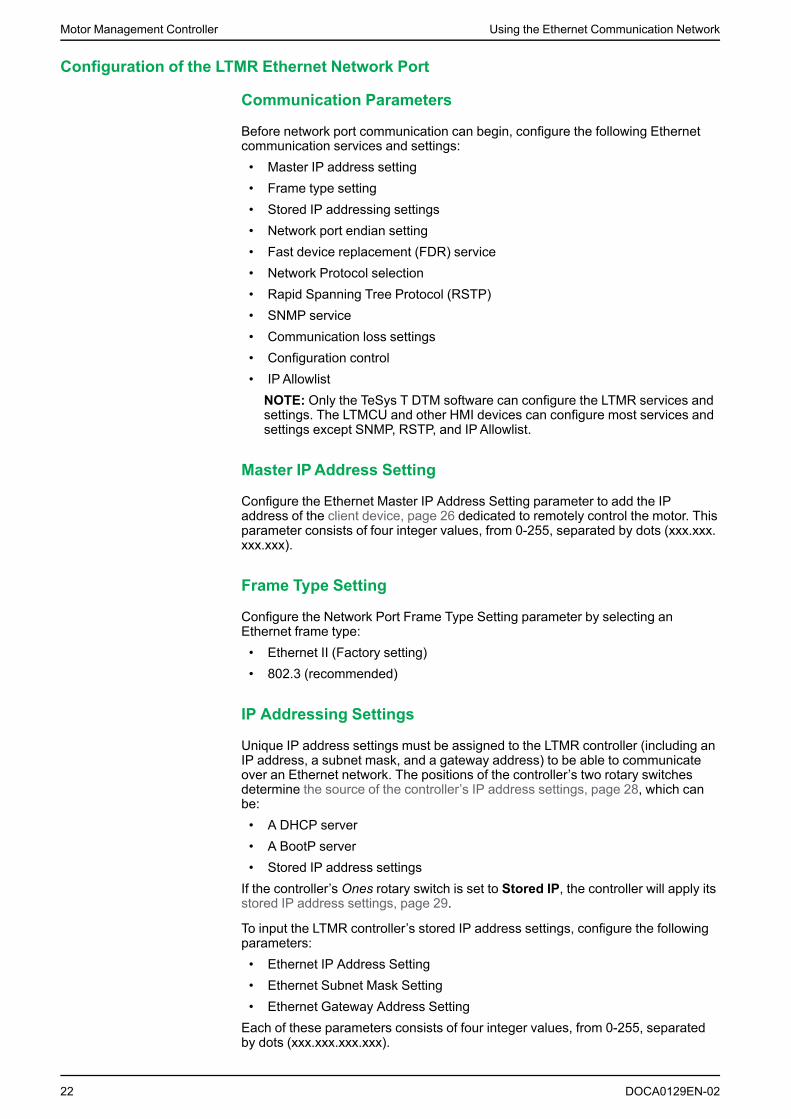
Before network port communication can begin, configure the following Ethernetcommunication services and settings:• Master IP address setting• Frame type setting• Stored IP addressing settings• Network port endian setting• Fast device replacement (FDR) service• Network Protocol selection• Rapid Spanning Tree Protocol (RSTP)• SNMP service• Communication loss settings• Configuration control• IP AllowlistNOTE: Only the TeSys T DTM software can configure the LTMR services andsettings. The LTMCU and other HMI devices can configure most services andsettings except SNMP, RSTP, and IPAllowlist.
Master IPAddress Setting
Configure the Ethernet Master IP Address Setting parameter to add the IPaddress of the client device, page 26 dedicated to remotely control the motor. Thisparameter consists of four integer values, from 0-255, separated by dots (xxx.xxx.xxx.xxx).
Frame Type Setting
Configure the Network Port Frame Type Setting parameter by selecting anEthernet frame type:• Ethernet II (Factory setting)• 802.3 (recommended)
IP Addressing Settings
Unique IP address settings must be assigned to the LTMR controller (including anIP address, a subnet mask, and a gateway address) to be able to communicateover an Ethernet network. The positions of the controller’s two rotary switchesdetermine the source of the controller’s IP address settings, page 28, which canbe:• A DHCP server• A BootP server• Stored IP address settingsIf the controller’s Ones rotary switch is set to Stored IP, the controller will apply itsstored IP address settings, page 29.
To input the LTMR controller’s stored IP address settings, configure the followingparameters:• Ethernet IP Address Setting• Ethernet Subnet Mask Setting• Ethernet Gateway Address SettingEach of these parameters consists of four integer values, from 0-255, separatedby dots (xxx.xxx.xxx.xxx).
22 DOCA0129EN-02

Using the Ethernet Communication Network Motor Management Controller
Network Port Endian Setting
The Network port endian setting allows to swap the two words in a double word.• 0 = least significant word first (little endian)• 1 = most significant word first (big endian, factory setting)
Fast Device Replacement Service
The Fast Device Replacement (FDR) , page 33 service stores the LTMRcontroller’s operating parameters on a remote server and, if the controller isreplaced, sends the replacement controller a copy of the original device’soperating parameters.
To enable the automatic backup of the controller’s operating parameters to theFDR server, configure the following parameters:• Network Port FDR Auto Backup Enable parameter. It can be set to:◦ No auto backup◦ Automatic backup (copies the parameters from the controller to the FDR
server)• Network Port FDR Controller Interval parameter: the time (in seconds)
between automatic backup transmissions.◦ Range = 30...3600 s◦ Increments = 10 s◦ Factory setting = 120 s
Network Protocol Setting
Select with this parameter the network protocol you want to use:• Modbus/TCP• EtherNet/IPNOTE: Enabling EtherNet/IP does not disable Modbus/TCP which is stillavailable for use with commissioning software such as SoMove. Only ModbusFunction Code 23 is disabled when enabling EtherNet/IP.
Rapid Spanning Tree Protocol
The Rapid Spanning Tree Protocol (RSTP) service manages the state on everyport of each device in the local area network (LAN) loop. The RSTP loopconfigured with 16 LTMR controllers and two RSTP-enabled switches typicallyperform to resolve a communication loss at the LTMR controller is 100 ms...200ms. Reconnection performances vary depending on PLC, services used, and IPaddress mode.
To enable the Rapid Spanning Tree Protocol (RSTP) service, set the parameterRSTP Disable to No.
On every network topology change, RSTP recalculates the optimum network path.It is recommended that network configuration does not change again during anRSTP operation. Following actions should be avoided on an operating network ornetwork performance can be temporarily impacted:• A network cable plug-out /plug-in or device power OFF/ON in less than 2 s• In a daisy chain loop, remove/add two nodes in less than 30 s
SNMP Service
The LTMR controller supports the Simple Network Management Protocol (SNMP),page 45. The LTMR controller includes a configurable SNMP agent that cancommunicate with up to two SNMP managers.
DOCA0129EN-02 23

Motor Management Controller Using the Ethernet Communication Network
NOTE: SNMP parameters can be configured only using the TeSys T DTMsoftware.
Refer to Configuring the SNMP Service, page 47 for more information aboutconfiguring SNMP parameters.
Network Port Comm Loss Settings
Configure the following parameters to determine how the LTMR controller willhandle communication loss with the PLC:• Ethernet Master IP address setting: declares which PLC will be the Master for
Network Port Comm loss strategy. For more information, refer to theexplanation of the Master IP, page 26
• Network Port Comm Loss Timeout: the length of time communication with thePLC defined as Master IP must be lost before the controller will detect aCommunication Loss fault or warning as well as activate Fallback strategy.◦ Range = 0...9999 s◦ Increments = 0.01 s◦ Factory setting = 2 s
• Network Port Fallback Action Setting: determines, with the controller’soperating mode, the behavior of logic outputs 1 and 2 when communicationwith the PLC that is declared as Master IP is lost. For more information, referto the explanation of the Master IP, page 26. Values include:◦ Hold◦ Run◦ O.1, O.2 OFF◦ O.1, O.2 ON◦ O.1 ON◦ O.2 ONThe factory setting is O.1, O.2 OFF.
• Network Port Fault Enable: signals a network fault after the Network PortComm Loss Timeout setting has expired.The factory setting is disable.
• Network Port Warning Enable: signals a network warning after the NetworkPort Comm Loss Timeout setting has expired.The factory setting is disable.
IPAllowlist
The IPAllowlist feature enables you to configure an Access Control List (ACL) ofIP addresses that are allowed to communicate with the LTMR. When enabled,device addresses that are not inside the Allowlist will be blocked fromcommunicating with the LTMR using Modbus/TCP, EtherNet/IP, or FTP. There arefive configurable IPAllowlist ranges. If configured, the Master IP address isautomatically included as an additional entry in the Allowlist. Configure with thefollowing settings:• IP Allowlist Enable setting: Enables or disables the IP Allowlist feature.
Disable by default.NOTE: At least one address has to be configured among the Master IP orAllowlist ranges to be enabled.
• IP Allowlist Range [N=1-5] Address setting: Host identifier address used inconjunction with the subnet mask. Must be within the device operatingsubnet. Valid values 0.0.0.0 through 255.255.255.255. Default value 0.0.0.0.
• IP Allowlist Range [N=1-5] Subnet Mask setting: Bitmask with most significantvalues contiguously set to 1, the least significant bits set to 0 define the sizeof the available address range. Valid values 255.255.255.0 (subnet size =
24 DOCA0129EN-02

Using the Ethernet Communication Network Motor Management Controller
256) through 255.255.255.255 (subnet size = 1). Default value255.255.255.0.
Subnet Mask Addresses in Subnet
255.255.255.255 1
255.255.255.254 2
255.255.255.252 4
255.255.255.248 8
255.255.255.240 16
255.255.255.224 32
255.255.255.192 64
255.255.255.128 128
255.255.255.0 (default) 256
Ethernet Link Management
Overview
The LTMR controller can receive or provide Ethernet services only if an Ethernetcommunications link exists. An Ethernet communications link can exist only whena cable connects one of the controller’s network ports to the network. If no networkcable connection exists, no Ethernet service can start.
The behavior of the controller is described in each of the following situations:• The LTMR powers up with no Ethernet communications link.• An Ethernet Communications Link is connected to a previously unconnected
controller after startup.• All Ethernet Communication Links disconnected from the controller after
startup.• One (or more) Ethernet Communication Links are re-established to a
controller after all Ethernet Communication Links had previously beendisconnected.
No Ethernet Communications Link while LTMR is Powered Up
When the LTMR powers up with no network cable connected, the LTMR• Signals an FDR fault if the rotary switches are in DHCP position,• Signals an FDR fault for 10 s and then clears the detected fault automatically
if the rotary switches are in Stored, BootP, ClearIP, or Disabled positions.
No Ethernet Communications Link at Startup
When, after controller startup, an Ethernet network cable is initially attached to apreviously unconnected controller• The controller starts its IP addressing service, page 28, which◦ Obtains IP address settings,◦ Validates IP address settings,◦ Checks that the obtained IP address settings are not duplicate,◦ Assigns the received IP address settings to the controller.
• After its IP address settings are assigned, the controller◦ Starts the FDR service and obtains its operating parameter settings, then◦ Starts its Modbus service.
The time to recover the link and start Ethernet services takes about 1 second.
DOCA0129EN-02 25

Motor Management Controller Using the Ethernet Communication Network
Ethernet Communications Link Disconnected After Startup
When all Ethernet Communication Links are disconnected from the controller afterstartup:• The IP addressing service is disabled and a Network Port Configuration
Warning (warning code 555) is generated,• All Modbus service connections are reset,• If a Master IP connection exists and:◦ The link cannot be re-established before the Network Port Comm Loss
Timeout expires, the controller enters its pre-configured fallback state ifthe LTMR is in Network control,
◦ The link is re-established before the Network Port Comm Loss Timeoutexpires, the connection to the Master IP is maintained, and the controllerdoes not enter its fallback state.
Link Reconnected After Disconnection
When one or more Ethernet Communication Links are re-established to thecontroller, after all Ethernet Communication Links had been disconnected afterstartup, the controller performs many, but not all, of the same tasks as when thereis no Ethernet Communication Link at Startup , page 25. Specifically, the controller• Presumes the previously obtained IP address settings remain valid, then◦ Checks that the IP address settings are not duplicate,◦ Re-assigns the IP address settings to the controller.
• After the IP address settings are assigned, the controller◦ Starts its FDR service and obtains its operating parameter settings, then◦ Starts its Modbus service.
The time to recover the link and start Ethernet services takes about 1 second.
Master IP
Overview
Each LTMR controller, in its role as communication server, could be configured torecognize another Ethernet device (typically a PLC) as the client device thatcontrols the motor. This device is usually a device that initiates communication toexchange Process Data (control and status). The Master IP is the IP address ofthis device.
The PLC should continuously maintain at least one connection, called a virtualconnection, page 49 or socket, with the communication server.
If the virtual connection between the Master IP device and the LTMR server isdisrupted, the LTMR controller waits a prescribed time, the Network Port CommLoss Timeout, for a new connection to be established and application levelmessages sent between the Master IP device and the LTMR controller.
If a connection is not reopened and messages are not received from the Master IPbefore the timeout expires, the LTMR controller enters its fallback state, set by theNetwork Port Fallback Setting.
If application level communication is never established with the Master IP, then theComm Loss Timeout timer is never started; As a result Comm Loss Event andFallback states can never be reached.
26 DOCA0129EN-02

Using the Ethernet Communication Network Motor Management Controller
WARNINGLOSS OF CONTROL• Configure a server IP on the Ethernet network.• Do not use an IP address other than Master IP to send network start and
stop commands to the LTMR controller.• Design the Ethernet network to block unauthorized network start and stop
commands sent to the LTMR controller.Failure to follow these instructions can result in death, serious injury, orequipment damage.
Prioritized Master IP Connections with Modbus/TCP
Connections between the LTMR controller and the Modbus client has a priorityover connections between the controller and other Ethernet devices.
After the controller has reached its maximum number of eight simultaneousModbus connections, the controller must close an existing connection to be ableto open a new connection. If an additional connection is requested after themaximum number has been established, then the LTMR controller will close theconnection whose most recent transaction is the oldest (least fresh) in order toestablish the new connection.
All connections (up to eight) between the LTMR controller and the Master IP clientare preserved once communication has been established between them. Thecontroller will not close a connection with the Master IP address in order to open anew connection from a non-Master IP address.
Configuring Master IP
To enable connections to be made to a Modbus client, use a configuration tool toconfigure the following parameters:
Parameter Setting Range Factory Setting
Ethernet Master IP address setting (3010-3011) Valid Class A, B, and C addresses in therange:
0.0.0.0 - 255.255.255.255
where 0.0.0.0 = Fallback disabled
0.0.0.0
= No Master IP
Network port comm loss timeout (693) Range = 0.010...99.99 s
Register value = 1...9999 in units of 10ms
2 s
Network port fallback setting (682) • Hold• Run• O.1, O.2 OFF• O.1, O.2 ON• O.1 ON• O.2 ON
O.1, O.2 OFF
DOCA0129EN-02 27

Motor Management Controller Using the Ethernet Communication Network
IP Addressing
Overview
The LTMR controller must obtain a unique IP address, subnet mask, and gatewayaddress to communicate over an Ethernet network. The settings of the two rotaryswitches on the front of the LTMR controller determine the source of theserequired settings. These settings are applied only on power-up. The rotaryswitches look like this:
The settings of the rotary switches determine the source of the LTMR controller’sIP address parameters and the FDR service activation, as follows:
Left Switch (Tens) Right Switch (Ones) Source of IP Parameters
0-151 0-91 DHCP server and FDR service
N/A2 BootP BootP server
N/A2 Stored LTMR configured settings are used. If not set then, IP parametersare derived from the MAC address.
N/A2 Clear IP Clears the stored IP settings. No IP addressing settings areassigned. The network port is disabled.
N/A2 Disabled The LTMR controller is not available for network communication.The LTMR controller does not initiate any IP acquisition process(host register, DHCP...) or announcements of IP on the network.Detection of network related faults does not occur.
However, the LTMR controller stays active on at the Ethernetswitch level allowing the daisy chain to function normally.
IP settings are assigned to the following parameters:• Ethernet IP Address• Ethernet subnet Mask• Ethernet Gateway
Getting IP Parameters from a DHCP Server
To obtain IP parameters from a DHCP server, point each rotary switch to anumerical setting, as follows:
Step Description
1 Set the left (Tens) rotary switch to a value from 0-15, and
2 Set the right (Ones) rotary switch to a value from 0-9
Device Name: The settings of the two rotary switches are used to determine eachLTMR controller’s device name. The device name consists of a fixed part("TeSysT") and a dynamic part, composed of:
The two-digit value (00-15) of the Tens rotary switch (xx)
28 DOCA0129EN-02
1. The two switches yield a value from 000-159, which uniquely identifies the device to the DHCP server. In the above figure, this value is084, which is the concatenation ofL the Tens switch (08) and the Ones switch (4). The individual values of the of each rotary switch, inthis case 08 and 4, are incorporated into the device name as described in Getting IP Parameters from a DHCP Server, page 28.
2. The left (Tens) rotary switch is not used. The right (Ones) rotary switch alone determines the source of IP parameters.

Using the Ethernet Communication Network Motor Management Controller
The one-digit value (0-9) of the Ones rotary switch (y)
The DCHP server must be pre-configured with the LTMR controller’s device nameand its associated IP parameters. When the DHCP server receives the LTMRcontroller’s broadcast request, it returns:• The LTMR controller’s:◦ IP address◦ Subnet mask◦ Gateway address
• The DHCP server’s IP addressNOTE:While the IP address is not provided by the DHCP server, the TeSys Tdetects a network port FDR major fault (Alarm LED steady red).NOTE: The LTMR controller uses the DHCP server’s IP address during theFast Device Replacement (FDR) process , page 28, when making an TFTPrequest for device configuration parameters.
In the figure, above, the device name is: TeSysT084.NOTE: The DHCP server can provide an IP address to a client device onlyafter the DHCP server has been configured with the Device Name, describedabove, for a client device.
Getting IP Parameters from a BootP Server
To obtain IP parameters from a BootP server, point the right (Ones) rotary switchto either of the two BootP settings. (The left (Tens) rotary switch is not used.) TheLTMR controller broadcasts a request for IP parameters to a BootP server, andincludes its MAC address in the request.
The BootP server must be pre-configured with the LTMR controller’s MACaddress and associated IP parameters. When the BootP server receives theLTMR controller’s broadcast request, it returns to the LTMR controller it's:• IP address• Subnet mask• Gateway addressNOTE: The Fast Device Replacement (FDR) service is not available if theLTMR controller is configured to receive IP parameters from a BootP server.
Using Stored IP Parameters
You can configure the LTMR controller to apply IP settings that have beenpreviously configured and stored in the device itself. These stored IP parameterscan be configured using your choice of configuration tool.
To apply stored IP parameters set the right (Ones) rotary switch to either of thetwo Stored positions. (The left (Tens) rotary switch is not used.)
The LTMR controller uses as its:• IP address: the Ethernet IP Address Setting parameter• Subnet mask: the Ethernet Subnet Mask Setting parameters• Gateway address: the Ethernet Gateway Address Setting parameterNOTE: If these parameters are not pre-configured, the LTMR controller cannotapply stored settings, but instead applies default IP parameters, as describedbelow.NOTE: The FDR service is not available when the LTMR controller isconfigured to use stored IP parameters.
DOCA0129EN-02 29

Motor Management Controller Using the Ethernet Communication Network
Configuring Default IP Parameters from the MAC Address
The LTMR controller derives its default IP parameters from its MAC address(stored in the device’s Ethernet MAC Address parameter). The MAC address is aunique identifier associated with the device’s network interface card (NIC).
As a prerequisite for using the default IP address, all bytes of the configured IPaddress must be set to zero.
To apply the LTMR controller’s default IP parameters, you must proceed in twosteps:
Step Action
1 Clear the existing IP address by setting the right (Ones) rotary switch to Clear IP, then cycle power.
2 Apply the stored IP address settings by setting the right (Ones) rotary switch to Stored, then cycle power.
The default IP parameters are generated as follows:• The first two byte values of the IP address are always 85.16• The last two byte values of the IP address are derived from the last two bytes
of the MAC address• The default subnet masks are always 255.0.0.0• The default gateway is the same as the device’s default IP addressFor example, for a device with a hexadecimal MAC address of 0x000054EF1001,the last two bytes are 0x10 and 0x01. These hexadecimal values translate todecimal values of 16 and 01. The default IP parameters for this MAC address are:• IP address: 85.16.16.01• Subnet mask: 255.0.0.0• Gateway address: 85.16.16.01NOTE: The Fast Device Replacement (FDR) service is not available when thedefault IP parameters are used.
30 DOCA0129EN-02

Using the Ethernet Communication Network Motor Management Controller
IP Assignment Process
As depicted in the following graphic, the LTMR controller performs a sequence of inquiries to determine its IPaddress:
NOTE: The Fast Device Replacement (FDR) service is not available when thedefault IP parameters are used.
DOCA0129EN-02 31

Motor Management Controller Using the Ethernet Communication Network
The following diagram depicts the assign default IP address process, referencedabove:
IP Assignment and STS/NS LED
During the IP address assignment process while the LTMR is operating normallyand has not detected a fault condition, the green STS/NS LED may indicate thefollowing conditions:
Switch Setting(s) STS/NS LED Behavior Description
BootP Flashes five times, then repeats The controller sent a BootP request, but the BootP server did notdeliver valid, unique IP address settings. Waiting for BootP server.
Flashes five times, then solid ON The controller sent a BootP request, and the BootP server deliveredvalid and unique IP address settings.
Stored Solid ON The LTMR controller is configured with valid, unique stored IP addresssettings.
Flashes six times, then repeats No valid, unique IP parameters are stored. Default IP settings aregenerated using the MAC address.
Clear IP Flashes two times, then repeats IP address settings have been cleared. No IP address settings areavailable. Controller cannot communicate using its Ethernet networkports.
Disabled STS/NS LED = Solid OFF The LTMR controller is not available for network communication. TheLTMR controller does not initiate any IP acquisition process (hostregister, DHCP, and so on) or announcements of IP on the network.Network error detection is not enabled.
However, the LTMR controller stays active at the Ethernet switch levelallowing the daisy chain to function normally.
Left (Tens) switch set to0-15 (xx)
Right (Ones) switchesset to 0-9 (y)
Flashes five times, then repeats The controller sent a DHCP request for device name (TeSysTxxy), butthe DHCP server did not deliver valid, unique IP address settings.Waiting for DHCP server.
Flashes five times, then solid ON The controller sent a DHCP request for device name (TeSysTxxy), andthe DHCP server delivered valid and unique IP address settings.
32 DOCA0129EN-02

Using the Ethernet Communication Network Motor Management Controller
NOTE: A repeating series of eight flashes by the STS/NS LED indicates thedetection of an unrecoverable FDR fault condition. The causes and potentialcures for an unrecoverable FDR fault include:• An internal communication fault within the LTMR controller: Cycle power
to the controller; if that does not clear the fault, replace the controller.• An invalid configuration of the Ethernet properties (typically IP address
settings or the Master IP address): Verify the IP address parametersettings.
• An invalid or corrupt operating parameter file: Transfer a correctedparameter file from the controller to the parameter file server, page 37.The transfer of a parameter file to the FDR server is only available withthe LTMR controller Ethernet version.
Fast Device Replacement
Overview
The FDR service employs a central server to store both the IP addressingparameters and the operating parameters for an LTMR controller. When a LTMRcontroller is replaced, the server automatically configures the replacement LTMRcontroller with the same IP addressing and operating parameters as the replacedcontroller.
NOTE: The FDR service is available only when the controller’s Ones rotaryswitch is set to integers. The FDR service is not available when the Onesrotary switch is set to BootP, Stored, Clear IP, or Disabled.
The FDR service includes configurable commands and settings that you canaccess using your choice of configuration tool. These commands and settingsinclude:• Commands that let you manually:◦ Backup the LTMR controller’s operating parameters, by uploading a copy
of the device’s parameter file to the server from the controller, or◦ Restore the LTMR controller’s parameters, by downloading a copy of the
device’s operating parameter file from the server to the controller.• Settings that cause the FDR server to automatically synchronize the
operating parameter files, in both the LTMR controller and the server, atconfigurable time intervals. If a difference is detected, a parameter file is sentfrom the controller to the FDR server (auto backup).
DOCA0129EN-02 33

Motor Management Controller Using the Ethernet Communication Network
FDR Compatibility
TeSys T
FDR Server
The table below describes the compatibility of firmware versions between the datastored on an FDR server (PLC) and the new FDR client (TeSys T). Firmware 2.9and above manages compatibility with previous versions stored FDR files.Firmware 2.8 and below does not manage compatibility, so the firmware andhardware versions must match.
FDR Client (TeSys T)
FW 2.6 and below FW 2.7 and 2.8 FW 2.9+
FDRSe
rver
(StoredFile) FW 2.6 and
below
FW 2.7 and 2.83
FW 2.9+
NOTE:• Accessories/Expansion module versions do not affect FDR compatibility.• Custom Logic backup using FDR is included since FW 2.4.
Preconditions to FDR
Before the FDR services can function, the FDR server must be configured with:• The LTMR controller’s network address and related IP addressing
parameters, this is done as part of the IP addressing service, page 28,• A copy of the LTMR controller’s operating parameter file, this can be sent
from the controller to the server either manually or automatically, as describedbelow. This will be a zero size file when unconfigured.
FDR and Custom Logic File
The FDR service saves custom logic to the operating parameters file if the customlogic file size is less than 3 kB (1.5 k Tokens as compiled in SoMove).
If the custom logic file size is more than 3 kB (1.5 k Tokens as compiled inSoMove), only the operating parameters are saved.
In this case, when you are replacing a device with a custom logic file size biggerthan 3 kB (1.5 k Tokens as compiled in SoMove), the STS/NS LED of the newdevice flashes eight times signaling the detection of an unrecoverable FDR faultcondition.
To resolve the fault and resume operations:
Step Action
1 Use the TeSys T DTM software to download the custom logic file
2 Cycle power to the LTMR controller
FDR Process
The FDR process consists of three parts:• The assignment of IP address settings,• A check of the operating parameter file at every LTMR controller startup,
34 DOCA0129EN-02
3. The replacement TeSys T must have the same hardware generation (MBTCP or MBTCP+EIP) , page 16.

Using the Ethernet Communication Network Motor Management Controller
• If auto synchronization is enabled, periodic checks of the LTMR controller’soperating parameter file from the FDR server.
These three processes are described below:
IP address settings assignment process:
Sequence Event
1 Service personnel use the rotary switches on the front of the replacement LTMR controller to assign it the samenetwork address (000-159) as the replaced device.
2 Service personnel place the replacement LTMR controller on the network.
3 The LTMR controller automatically sends a DHCP request to the server for its IP parameters.
4 The server sends the LTMR controller:• IP parameters, including:
◦ IP address◦ Subnet mask◦ Gateway address
• The server’s IP address
5 The LTMR controller applies its IP parameters.
FDR startup process:
Sequence Event
6 • If FDR Auto Restore is enabled in the FDR configuration screen:
a The controller sends a request to the FDR server for a copy of the served configuration file.
b The FDR server sends the controller a copy of the served file.
c The controller checks the served file’s version number and size for compatibility with the device. If the served fileis• Compatible, the served file is applied,• Not compatible, the controller will attempt to manage the compatibility and upload the new file to the
server. If not able to manage the compatibility, then it enters a critical internal fault state 4.
Notes:
1. Because the factory setting of FDR Auto Restore is enabled, a new LTMR controller always downloads andattempts to apply a served file on initial startup.
2. If the downloaded file is empty, the controller will use its local file and send a copy of that file to the server.
• If FDR Auto Restore is disabled: The controller applies the operating parameter file stored in the LTMRcontroller’s non-volatile memory.
7 The LTMR controller resumes operation.
FDR Auto Backup process:
Sequence Event
8 The controller checks the Network Port FDR Auto Backup Period Setting (697) parameter to determine if the FDRauto-synchronization timer has expired.
9 If the timer has:• Not expired: No action is taken.• Expired: The controller checks the Network Port FDR Auto Backup Enable (690.3) parameter.
10 If the Network Port FDR Auto Backup Enable (690.3) parameter is:• Auto backup (1): The controller sends a copy of the local file to the FDR server.• No synchro (0): The controller takes no action.
11 The LTMR controller resumes operation.
DOCA0129EN-02 35
4. In the event the controller enters the Not Ready state, the underlying problem must be resolved, and power must be cycled to thecontroller before operations can resume.

Motor Management Controller Using the Ethernet Communication Network
The following diagrams describe the controller’s FDR processes after theassignment of an IP address (see IP Assignment Process, page 31):
FDR Auto Restore Diagram
Startup
Yes
Yes
No
No
No
No
No
Yes
Yes
Yes
Is FDRAuto-RestoreEnabled?
Use LocalConfiguration
GetServed File
Is ServedFile Empty?
Send LocalFile to Server
Is Served File different than Local?
Is Served File Version #different?
Send LocalFile to Server
Update LocalConfiguration
Reboot
Operating
Is Served FileCompatable?
RecoverableEvent
36 DOCA0129EN-02

Using the Ethernet Communication Network Motor Management Controller
FDR Auto Backup Diagram
Yes
Yes
Yes
No
No
No
FDR AutoBackup TimerExpired?
GetServed File
FDR AutoBackupEnabled?
Send LocalFile to Server
Operating
Are Remote/Local FilesDifferent?
Configuring FDR
The FDR service monitors the operating parameter file maintained in your LTMRcontroller and compares it against the corresponding operating parameter filestored in the server.
When the FDR service detects a discrepancy between these two files:• The Network Port FDR Status, page 39 parameter is set, and• The two operating parameter files, one in the server, the other in the
controller, must be synchronized.Synchronizing operating parameter files can be performed either automatically ormanually, using your choice of configuration tool.
NOTE: A new configuration file can cause the LTMR to reboot. This can affectother devices such as other LTMR downstream in a daisy chain topology.
Automatically Backup Settings: By setting the following parameters, you canconfigure your LTMR controller to automatically synchronize its operatingparameters with the FDR server:
Parameter Name Description
Network Port FDR Auto Backup Enable Use this setting to enable/disable automatic synchronization of the operatingparameter files. Selections are:• No auto backup: Automatic file synchronization is turned OFF (parameter =
0).• Auto backup: Automatic file synchronization is turned ON, and the file in
the controller will be copied to the server in case of discrepancy (parameter= 1).
Network Port FDR Auto Backup Period Setting The frequency, in seconds, between comparisons of the parameter file in thecontroller against the parameter file stored in the server.• Range = 30...3600 s• Increments = 10 s• Factory setting = 120 s
DOCA0129EN-02 37

Motor Management Controller Using the Ethernet Communication Network
NOTE:When automatic synchronization is enabled, it is recommended to setthe Network Port FDR Auto Backup Period Setting parameter to a valuegreater than 120 s.
Manually Backup and Restore Settings: By executing the commands describedbelow, you can manually synchronize the operating parameter files in thecontroller and server:
Command Name Description
FDR Manual Backup Command Copies the operating parameter file in the controller to the server.
FDR Manual Restore Command Copies the operating parameter file in the server to the controller.
NOTE:• If the FDR Manual Backup Command and FDR Manual Restore
Command bits are set to 1 simultaneously, only the FDR Manual RestoreCommand is processed.
• FDR Manual Restore Command is available whether Config via networkis enabled or not.
• FDR Manual Restore Command cannot be triggered while the LTMRdetects current.
• Any time the LTMR controller configuration changes, you should manuallybackup the new configuration file to the server by following the LTMCUmenu structure or using SoMove and clicking Device > File transfer >backup command.
FDR Fault Recovery
When the LTMR controller experiences a critical fault that requires interventionduring the FDR startup process, the STS/NS LED flashes as follows:
Number of Flashes... Indicates the Fault is...
Eight flashes per second LTMR Recoverable
10 flashes per second System Recoverable
System recoverable faults:
Operations can resume after fixing the cause of the fault outside of the LTMR.System recoverable faults include:• No response from IP server (Network Port FDR Status = 1).• The parameter file server, or TFTP service, is unavailable (Network Port FDR
Status = 2)• No file on the parameter server (Network Port FDR Status = 3)LTMR recoverable faults:
When the parameter file in the server is invalid or corrupt, the fault requiresmanual intervention to be cleared. Operations can resume only after a newparameter file is manually copied from the controller to the server using the FDRData Backup Command and power is cycled to the controller. LTMR recoverablefaults include:• Version mismatch of the parameter file on the parameter server and the
LTMR controller (Network Port FDR Status = 13)• CRC mismatch between parameter file on the server and the LTMR controller
(Network Port FDR Status = 9)• Content of the parameter file is invalid (Network Port FDR Status = 4)
38 DOCA0129EN-02

Using the Ethernet Communication Network Motor Management Controller
Incompatible FDR File on Server
This method updates an incompatible FDR file stored on the FDR server when anexisting LTMR controller is replaced.
Step Action
1 Configure new LTMR offline.
2 Ensure that “FDR disable” = yes (so that the old file will not be loaded to the new LTMR).
3 Cycle power to the LTMR for network settings to take effect.
4 Connect new LTMR to network with DHCP (code wheels).
5 After IP Address is assigned, you can re-enable FDR.NOTE: Do not power off in this step.
6 From SoMove or LTMCU, select “backup” to store/overwrite the file on the FDR server.
7 Cycle power to the LTMR, there should be no detected fault.
FDR Status
The Network Port FDR Status parameter describes the state of the FDR service,as described below.
FDR Status:
Value Description
0 Ready, IP available
1 No response from IP server
2 No response from parameter server
3 No file on parameter server
4 Corrupt file on parameter server
5 Empty file on parameter server
6 Detection of Internal Communication fault
7 Backup of settings from Device to Parameter Server unsuccessful
8 Invalid settings provided by the controller
9 CRC mismatch between parameter server and controller
10 Invalid IP
11 Duplicate IP
12 FDR disabled
13 Device Parameter File Version Mismatch (for example, when attempting to replace an LTMR 08 EBD with an LTMR100 EBD)
FDR Restore Status
The FDR Restore Status parameter describes the state of the most recent FDRRestore process as described below:
Value Description
0 OK, Success
1–600 Index into the FDR stored settings which is unable to write
0xFFFD Incorrect load CT values
0xFFFE Incorrect ground current CT values
0xFFFF Incorrect commercial reference number
DOCA0129EN-02 39

Motor Management Controller Using the Ethernet Communication Network
Discovery Procedure
Overview
Discovery is an automated method to identify and connect to a device with anunknown IP address, using a direct PC connection and a webpage accessinterface.
Discovery is only available on Microsoft Windows Vista, 7, 8, and 10 operatingsystems.
Step Automated Action
1 Connect the PC to the TeSys T using a RJ45 cable.
2 • Open Windows Explorer• Expand Network to view all network connections• The Connected device should appear in the list within a few seconds
3 Double-click the connected TeSys T.
The name of the TeSys T is:• TeSys T-XXYYZZ (where XXYYZZ are the last three bytes of MAC address in
hexadecimal format) if TeSys T is not configured in DHCP mode.• TeSys T-XYZ (where XY is the position of Tens rotary switch and Z is the position
of Ones rotary switch) if TeSys T is configured in DHCP mode.
4 Access the TeSys T in the webpage interface.
NOTE: If the product cannot be detected, deactivate the antivirus and thefirewall and then retry.
Ethernet Diagnostics
Overview
The LTMR controller reports diagnostic data describing its Ethernet networkcommunications interface, including:• Data parameters that describe the controller’s:◦ IP addressing settings◦ IP address assignment processes◦ Virtual connections◦ Communication history◦ Communication services and their status
• One parameter that describes the validity of the data in each data parameterNOTE: It is recommended to read the diagnostics registers every second.NOTE: The response to the first request contains either all zeros or old data.The response to the second and subsequent requests contains currentnetwork port diagnostic data.
Ethernet Basic Diag Validity
The Ethernet Basic Diag Validity parameter evaluates and reports the validity ofEthernet network diagnostic data. A bit in this parameter represents the state of anassociated Ethernet network data parameter.
Bit values are:
Value Indicates the Parameter Data is...
0 Invalid
1 Valid
40 DOCA0129EN-02

Using the Ethernet Communication Network Motor Management Controller
The Ethernet Basic Diag Validity parameter is 32 bits long.
The bits of this parameter represent the validity of the following Ethernet dataparameters:
Bit Describes the Validity of Data in this Parameter...
0 IP address assignment mode
1 Ethernet device name
2 Ethernet MB messages received counter
3 Ethernet MB messages sent counter
4 Ethernet MB error messages sent counter
5 Ethernet opened servers counter
6 Ethernet opened clients counter
7 Ethernet transmitted correct frames counter
8 Ethernet received correct frames counter
9 Ethernet frame format
10 Ethernet MAC address
11 Ethernet gateway
12 Ethernet subnet mask
13 Ethernet IP address
14 Ethernet service status
15 (not applicable - always 0)
16 Ethernet services
17 Ethernet global status
18-31 (Reserved - always 0)
Ethernet Global Status
The Ethernet Global Status parameter indicates the status of the followingservices provided by the LTMR controller:• Fast device replacement (FDR)• SNMP network management• Modbus port 502 messaging (Modbus/TCP only)This parameter is 2 bits long.
Parameter values are:
Bit Indicates...
0 At least one enabled service is operating with an unresolved detected error
1 All enabled services are operating without error
Ethernet Global Status is cleared on power cycle and controller reset.
Ethernet Services Validity
The Ethernet Services Validity parameter indicates whether the LTMR controllersupports the port 502 messaging service.
NOTE: Port 502 is exclusively reserved for Modbus messages.The Ethernet Supported Services parameter is 1 bit long.
DOCA0129EN-02 41

Motor Management Controller Using the Ethernet Communication Network
Parameter values are:
Value Indicates the Port 502 Messaging Service is...
0 Not supported
1 Supported
Ethernet Services Status
The Ethernet Services Status parameter indicates the status of the EthernetSupported Services parameter, that is, the status of the controller’s port 502messaging service.
This parameter is 3 bits long.
Parameter values are:
Value Indicates the Port 502 Messaging Service is...
1 Idle
2 Operational
Ethernet Services Status is cleared on power cycle and controller reset.
Ethernet IP Address
The Ethernet IP Address parameter describes the IP address that has beenassigned to the LTMR controller by the IP address assignment process, page 28.
The Ethernet IP Address consists of 4 byte values, in dot-decimal notation. Eachbyte value is an integer from 000-255.
Ethernet Subnet Mask
The Ethernet Subnet Mask parameter is applied to the Ethernet IP Address valueto define the host address of the LTMR controller.
The Ethernet Subnet Mask consists of 4 byte values, in dot-decimal notation.Each byte value is an integer from 000-255.
Ethernet Gateway Address
The Ethernet Gateway Address parameter describes the address of the defaultgateway, that is, the node that serves as an access point to other networks forcommunications from or to the LTMR controller.
The Ethernet Gateway Address consists of 4 byte values, in dot-decimal notation.Each byte value is an integer from 000-255.
Ethernet MAC Address
The Ethernet MAC Address parameter describes the media access control (MAC)address, or hardware identifier, uniquely assigned to an LTMR controller.
The Ethernet MAC Address consists of six hexadecimal byte values, from 0x00-0xFF.
Ethernet II Framing
The Ethernet II Framing parameter describes the Ethernet frame formatssupported by the LTMR controller, including:• Capability: can the device support a frame format?
42 DOCA0129EN-02

Using the Ethernet Communication Network Motor Management Controller
• Configuration: is the device configured to support a frame format?• Operational: is the configured frame format operating successfully?NOTE: The Ethernet frame type, Ethernet II or 802.3, is configured using theNetwork Port Frame Type Setting parameter.
This parameter is three words long.
Ethernet II framing data is stored as follows:
Word Bit Description Values
1 0 Ethernet II framing supported • 0 = not supported• 1 = supported
1 Ethernet II framing receiver supported • 0 = not supported• 1 = supported
2 Ethernet II framing sender supported • 0 = not supported• 1 = supported
3 Ethernet auto detection supported • 0 = not supported• 1 = supported
4-15 (Reserved) always 0
2 0 Ethernet II framing configured • 0 = not configured• 1 = configured
1 Ethernet II framing receiver configured • 0 = not configured• 1 = configured
2 Ethernet II framing sender configured • 0 = not configured• 1 = configured
3 Ethernet auto detection configured • 0 = not configured• 1 = configured
4-15 (Reserved) always 0
3 0 Ethernet II framing operational • 0 = not operational• 1 = operational
1 Ethernet II framing receiver operational • 0 = not operational• 1 = operational
2 Ethernet II framing sender operational • 0 = not operational• 1 = operational
3 Ethernet auto detection operational • 0 = not operational• 1 = operational
4-15 (Reserved) always 0
Ethernet Received Correct Frames Counter
The Ethernet Received Correct Frames Counter parameter contains a count ofthe total number of Ethernet frames that have been successfully received by theLTMR controller.
This parameter is an UDInt parameter. It is cleared on power cycle and controllerreset.
The Ethernet Received Correct Frames Counter consists of four hexadecimalvalues, from 0x00-0xFF.
Ethernet Transmitted Correct Frames Counter
The Ethernet Transmitted Correct Frames Counter parameter contains a count ofthe total number of Ethernet frames that have been successfully transmitted bythe LTMR controller.
DOCA0129EN-02 43

Motor Management Controller Using the Ethernet Communication Network
This parameter is an UDInt parameter. It is cleared on power cycle and controllerreset.
The Ethernet Transmitted Correct Frames Counter consists of four hexadecimalvalues, from 0x00-0xFF.
Ethernet Opened Clients Counter
The Ethernet Opened Clients Counter parameter contains a count of the numberof open TCP client connections. It applies only to devices with TCP clients.
This parameter is an UInt parameter. It is cleared on power cycle and controllerreset.
The Ethernet Opened Clients Counter consists of two hexadecimal values, from0x00-0xFF.
Ethernet Opened Servers Counter
The Ethernet Opened Servers Counter parameter contains a count of the numberof open TCP server connections. It applies only to devices with TCP servers.
This parameter is an UInt parameter. It is cleared on power cycle and controllerreset.
The Ethernet Opened Servers Counter consists of two hexadecimal values, from0x00-0xFF.
Ethernet MB Error Messages Sent Counter
The Ethernet MB Error Messages Sent Counter parameter contains a count of thenumber of:• EtherNet/IP or Modbus/TCP request packets with detected errors in the
header that have been received by this LTMR controller (does not countdetected errors in the data portion of EtherNet/IP or Modbus/TCP requestpackets)
• EtherNet/IP or Modbus/TCP exceptions due to incorrect combination ofphysical port and Unit ID , page 50
This parameter is an UDInt parameter. It is cleared on power cycle and controllerreset.
Ethernet MB Messages Sent Counter
The Ethernet MB Messages Sent Counter parameter contains the total number ofModbus messages, excluding Modbus error messages, that have been sent bythis LTMR controller.
This parameter is an UDInt parameter. It is cleared on power cycle and controllerreset.
Ethernet MB Messages Received Counter
The Ethernet MB Messages Received Counter parameter contains the totalnumber of Modbus messages that have been received by this LTMR controller.
This parameter is an UDInt parameter. It is cleared on power cycle and controllerreset.
Ethernet Device Name
The Ethernet Device Name parameter contains the 16 character string used toidentify the LTMR controller.
44 DOCA0129EN-02

Using the Ethernet Communication Network Motor Management Controller
This parameter is 16 bytes long.
Ethernet IP Assignment Capability
The Ethernet IP Assignment Capability parameter describes the available IPaddressing sources for the LTMR controller. Up to four different IP addressingsources can be described.
This parameter is 4 bits long.
The Ethernet IP Assignment Capability parameter stores data as follows:
Bit IPAddressing Source... Values
0 A DHCP server, using the device name set by the two rotary switches • 0 = not available• 1 = available
1 Derived from the MAC address. The Ones rotary switch is set to BootP, but no IPaddress was received from the server.
• 0 = not available• 1 = available
2 Derived from the MAC address. Both rotary switches are set to integers, but noIP address was received from the DHCP server.
• 0 = not available• 1 = available
3 The stored configuration parameters:• Ethernet IP Address Setting• Ethernet Subnet Mask Setting• Ethernet Gateway Address Setting
• 0 = not available• 1 = available
Ethernet IP Assignment Operational
The Ethernet IP Assignment Operational parameter describes how the current IPaddress was assigned to the LTMR controller. Only 1 (of 4) different IP addresssources can be operational at any one time.
This parameter is 4 bits long.
The Ethernet IP Assignment Operational parameter stores data as follows:
Bit IPAddressing Source... Values
0 A DHCP server, using the device name set by the two rotary switches • 0 = not operational• 1 = operational
1 Derived from the MAC address. The Ones rotary switch is set to BootP, but no IPaddress was received from the server.
• 0 = not operational• 1 = operational
2 Derived from the MAC address. Both rotary switches are set to integers, but noIP address was received from the DHCP server.
• 0 = not operational• 1 = operational
3 The stored configuration parameters:• Ethernet IP Address Setting• Ethernet Subnet Mask Setting• Ethernet Gateway Address Setting
• 0 = not operational• 1 = operational
Simple Network Management Protocol
Overview
The LTMR controller includes an SNMP version 3.0 agent that can connect to andcommunicate with an SNMPmanager via the UDP transport protocol over port161.
The SNMP service includes:• Automatic discovery and identification of the LTMR by an SNMP manager
over an Ethernet network
DOCA0129EN-02 45

Motor Management Controller Using the Ethernet Communication Network
• Authentication checking, by the LTMR controller, of any SNMP manager thatsends requests to the controller
• Management of event, or trap, reporting by the LTMR controller, including theidentification of two SNMP managers authorized to receive reports
• Full support of MIB-II (standard TCP/IP) parametersNOTE: Access to, and configuration of, the SNMP parameters is availableonly using the TeSys T DTM.
SNMP Agents and Managers
The SNMP management model uses the following terms and definitions:• Manager, the client application (for example, Connexium Network Manager
(CNM) or a simple MIB browser) running on the PC• agent, the server application running on a network device, in this case the
LTMR controllerAn SNMP manager communicates with an agent by sending queries for thepurpose of reading data from, and writing data to, the agent. An SNMP manageruses UDP to establish communications with an agent via an open Ethernetinterface.
Agents can also initiate communications with a manager by sending unsolicitedtrap messages, which report the occurrence of specific events.
SNMP Messages
SNMP supports the following types of messages between the manager and theagent:• Get: the manager requests an agent to send information.• Set: the manager requests an agent to change information stored by the
agent.• Response: the client replies to a Get or Set request.• Trap: the agent sends an unsolicited report to the manager that an event has
occurred.MIB-II defines the agent properties that the manager can Get or Set.
Trap Reporting
A trap is an agent-detected event that indicates either• A change has occurred in the status of the agent, or• An unauthorized manager device has attempted to get data from, or change
data on, the agentConfigure the LTMR controller’s SNMP agent to report traps to one or twoauthorized SNMP managers. Allows to enable or to disable certain traps.
The LTMR controller supports the following traps:
Trap Description Configurable in the TeSysT DTM?
Authentication Failure5 The agent received a request from an unauthorized manager. Yes (enable/disable)
Cold Start The agent is reinitializing and its configuration may be altered. No (always enabled)
Link Down One of the agent’s communication links is disrupted. No (always enabled)
Link Up One of the agent’s communication links has turned on. No (always enabled)
Warm Start The agent’s configuration has changed. No (always enabled)
46 DOCA0129EN-02
5. Refer to the official SNMP https://tools.ietf.org/html/rfc1157 website for terminology.
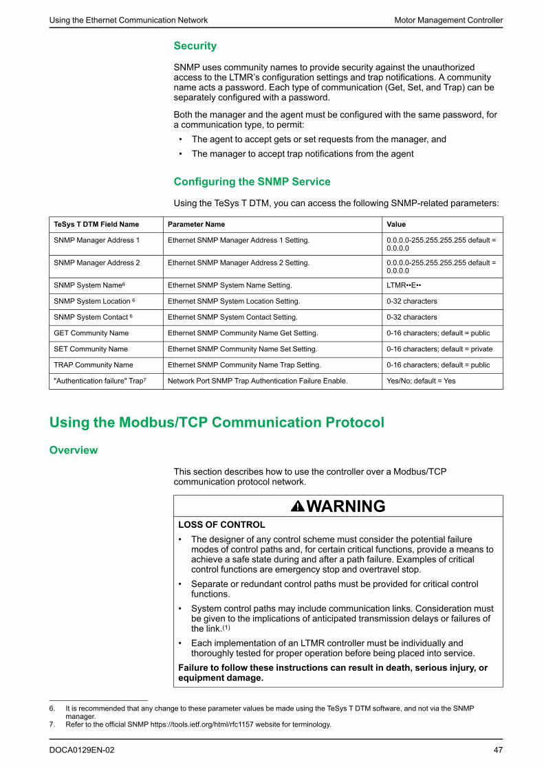
Using the Ethernet Communication Network Motor Management Controller
Security
SNMP uses community names to provide security against the unauthorizedaccess to the LTMR’s configuration settings and trap notifications. A communityname acts a password. Each type of communication (Get, Set, and Trap) can beseparately configured with a password.
Both the manager and the agent must be configured with the same password, fora communication type, to permit:• The agent to accept gets or set requests from the manager, and• The manager to accept trap notifications from the agent
Configuring the SNMP Service
Using the TeSys T DTM, you can access the following SNMP-related parameters:
TeSys T DTM Field Name Parameter Name Value
SNMP Manager Address 1 Ethernet SNMP Manager Address 1 Setting. 0.0.0.0-255.255.255.255 default =0.0.0.0
SNMP Manager Address 2 Ethernet SNMP Manager Address 2 Setting. 0.0.0.0-255.255.255.255 default =0.0.0.0
SNMP System Name6 Ethernet SNMP System Name Setting. LTMR••E••
SNMP System Location 6 Ethernet SNMP System Location Setting. 0-32 characters
SNMP System Contact 6 Ethernet SNMP System Contact Setting. 0-32 characters
GET Community Name Ethernet SNMP Community Name Get Setting. 0-16 characters; default = public
SET Community Name Ethernet SNMP Community Name Set Setting. 0-16 characters; default = private
TRAP Community Name Ethernet SNMP Community Name Trap Setting. 0-16 characters; default = public
"Authentication failure" Trap7 Network Port SNMP Trap Authentication Failure Enable. Yes/No; default = Yes
Using the Modbus/TCP Communication Protocol
Overview
This section describes how to use the controller over a Modbus/TCPcommunication protocol network.
WARNINGLOSS OF CONTROL• The designer of any control scheme must consider the potential failure
modes of control paths and, for certain critical functions, provide a means toachieve a safe state during and after a path failure. Examples of criticalcontrol functions are emergency stop and overtravel stop.
• Separate or redundant control paths must be provided for critical controlfunctions.
• System control paths may include communication links. Consideration mustbe given to the implications of anticipated transmission delays or failures ofthe link.(1)
• Each implementation of an LTMR controller must be individually andthoroughly tested for proper operation before being placed into service.
Failure to follow these instructions can result in death, serious injury, orequipment damage.
DOCA0129EN-02 47
6. It is recommended that any change to these parameter values be made using the TeSys T DTM software, and not via the SNMPmanager.
7. Refer to the official SNMP https://tools.ietf.org/html/rfc1157 website for terminology.

Motor Management Controller Using the Ethernet Communication Network
(1) For additional information, refer to NEMA ICS 1.1 (latest edition), "SafetyGuidelines for the Application, Installation, and Maintenance of Solid StateControl".
WARNINGUNEXPECTED RESTART OF THE MOTOR
Check that the PLC application software considers the change from local toremote control and appropriately manages the motor control commands duringthose changes.
Failure to follow these instructions can result in death, serious injury, orequipment damage.
When switching to the Network control channels, depending on thecommunication protocol configuration, the LTMR controller can take into accountthe latest known state of the motor control commands issued from the PLC andautomatically restart the motor.
Modbus/TCP Protocol Principle
Overview
The Modbus/TCP protocol is a client/server protocol:
1 Client (PLC, PC, or communication module)
2 Straight or crossed category 5 shielded/unshielded twisted-pair Ethernet cablewith RJ45 connector
Only one device can transmit in one direction over a segment at any time.
The client manages and initiates the exchange. It interrogates each of the serversin succession. No server can send a message unless it is invited to do so.
The client repeats the question when there is an incorrect exchange, and declaresthe interrogated server absent if no response is received within a given timeperiod.
If a server does not understand a message, it does nothing. It sends an exceptionresponse to the client when a message is understood but contains errors, or when
48 DOCA0129EN-02

Using the Ethernet Communication Network Motor Management Controller
the server is not able to handle the request (for example, due to resourceproblems). The client may or may not retransmit the request.
NOTE: For further details on Modbus function codes visit the website: http://modbus.org/specs.php
Modbus/TCP Dialog
Modbus/TCP supports only unicast dialogs, comprising requests made by a clientto a server and the server’s response.
Direct server-to-server communications are not possible. For server-to-servercommunication, the client must therefore interrogate a server and send back datareceived to the other server.
Modbus/TCP Messaging
Modbus/TCP is the Modbus protocol encapsulated in TCP. The Modbus/TCPcommunications protocol combines the:• Modbus application layer protocol (layer 7 of OSI model), which provides the
messaging structure for organizing and interpreting data, and• TCP transport layer protocol (layer 4 of the TCP/IP stack), which provides a
transmission medium for communications between devices on an Ethernetnetwork
The TCP frame, with embedded Modbus data, is sent via TCP to system port 502,which is exclusively reserved for Modbus applications, and added to a TCP/IPEthernet data packet for network transmission.
Virtual Connections
Although there can be either one or two physical connections between a client anda server-depending upon the network topology Modbus/TCP supports the use ofmultiple virtual connections.
A virtual connection - or socket - combines:• The client IP address (for example, the Modbus/TCP client)• A unique port on the server• The server IP address (the LTMR controller server)• A unique port on the client• The TCP protocolMultiple virtual connections enable multiple simultaneous - instead of serial -transactions between the client and the server.
Modbus/TCP supports several types of simultaneous client/server transactions, asfollows:
Transaction Type Limits on the Number of Simultaneous Virtual Connections
Modbus Eight maximum
Notes:• If a new connection is created when eight connections already exist, the new connection replaces the
pre-existing connection, whose most recent transaction is the oldest.• You can identify a connection as a Master IP connection, thereby preventing it from being automatically
replaced when the maximum number of connections is exceeded.
SNMP at least one
FDR one maximum
FTP at least one
DOCA0129EN-02 49

Motor Management Controller Using the Ethernet Communication Network
Modbus Requests
Modbus Requests
All physical communication ports–the LTME/HMI port and the two Ethernetnetwork ports are available for Modbus messaging:• Modbus/TCP using the network ports• Modbus RTU using the LTME/HMI portThe LTMR controller supports the following Modbus requests, which can beperformed using the physical ports and Unit ID/Server address combinationsdescribed below:
Function Code/Subcode
Request Description
Using These Port and Unit ID Combinations...
Network Port Modbus/TCP
LTME/HMI Port
Modbus RTU
3/- Read N output words (multiple registers) Unit ID = 0-254 Modbus address = 1-247
6/- Write one output word (single register) Unit ID = 0-254 Modbus address = 1-247
8/22 Read or clear diagnostic data Unit ID = 255 (Not available)
16/- Write N output words (multiple registers) Unit ID = 0-254 Modbus address = 1-247
23/- Read/write multiple registers Unit ID = 0-254 Modbus address = 1-247
43/14 Read identification (identification register) (Reserved) Modbus address = 1-247
NOTE: Not using the correct combination of physical port and Unit ID/Serveraddress will cause the LTMR controller to respond with a Modbus exception.
The maximum number of registers per request is limited to 100.NOTE: For further details on Modbus function codes visit the followingwebsite: http://modbus.org/specs.php
WARNINGUNINTENDED EQUIPMENT OPERATION• Use of this device on a Modbus network that uses the broadcast function
should be considered with caution.• This device has a large number of registers that must not be modified during
normal operation. Unintended writing of these registers by the broadcastfunction may cause unexpected and unwanted product operation.
• For more information, refer to the list Communication Variables, page 88.Failure to follow these instructions can result in death, serious injury, orequipment damage.
Modbus Exception Management
Overview
The LTMR controller generally follows the Modbus requirements for the ExceptionManagement.
Three special cases apply to the LTMR controller:• Bit-Field Registers• Exception Code 02 - Illegal Data Address• Exception Code 03 - Illegal Data Value
50 DOCA0129EN-02

Using the Ethernet Communication Network Motor Management Controller
Bit-Field Registers
Some registers in the Register Map are Bit field. Based on the LTMR controllerstate, some bits in those registers shall not be writable. In this case, the LTMRcontroller shall reject the write to those bits meaning that no exception shall bereturned. For example, bits that can be written only in configuration mode will beignored (no exception returned) if the LTMR controller is out of the configurationmode. The write to the bits not constrained by the LTMR controller state shallhowever occur.
Exception Code 02 - Illegal Data Address
In general, the LTMR controller shall return an illegal data address exception codeif the address is out of range or inaccessible. Specifically, the LTMR controllershall return an illegal data address if:• A Write request is sent to a Read only register.• The permission to write a register is not granted because of the LTMR
controller state: this is the case, for example, when a register that can bewritten only in configuration mode is written while the LTMR controller is out ofconfiguration mode.
Exception Code 03 - Illegal Data Value
In general, the LTMR controller shall return an illegal data value exception code ifthere is a problem with the structure of the message, such as an invalid length.The LTMR controller shall also use this exception code if:• The data to be written is out of range (for standard and Bit field registers): this
is the case if a write request of 100 is sent to a R/W register with a range of 0-50.
• A reserved bit or register is written to a value different than 0.• Motor low speed command (bit 704.6) is set while the motor controller mode
selected is not a two-speed mode of operation.
I/O Scanning Configuration
Mirroring High Priority Registers
The LTMR controller provides a block of nine contiguous registers dedicated toscanning that mirror the values and functionality of selected high priority registers,page 134.
The LTMR controller reads the values of all high priority registers whenever itdetects a change to any single high priority register, and writes the values of allhigh priority registers to the mirroring registers.
Because the mirroring registers are contiguous, it is possible to execute a singleModbus block read or block write request to these registers, thereby saving thetime it would take to make separate Modbus read/write requests directly to eachunderlying high priority register.
Mirroring Status
Mirroring status, page 134 is the first register, in the sequence of eight contiguousmirroring registers. Bits 0-2 of this register describe the status of read-onlycommands, and bits 8-10 describe the status of read/write commands, page 134.
NOTE: Use only the two Ethernet ports to read mirroring status register bitvalues. Using the HMI/LTME port produces an invalid, constant value of 0 foreach bit.
All other mirroring status registers can be read accurately using either theHMI/LTME port or the two Ethernet ports.
DOCA0129EN-02 51

Motor Management Controller Using the Ethernet Communication Network
Configuring I/O Scanning
Your success in configuring I/O scanning of registers depends upon:• The register type• The I/O scanning period• The I/O scanning health timeout periodTotal number of registers accessed (read and write) in I/O scan (counting therepeated registers also) shall not exceed 500 registers per second. This limit shallbe calculated with all the combinations of request and also take into accountmultiple connections. If there are multiple connections to the LTMR Controller, theI/O scanning and I/O scanning health timeout settings for read and writetransactions for registers are reduced. Any settings for I/O scan period or I/O scanhealth timeout, lower than described below, can cause the LTMR controller tosend Modbus exception packets.
For higher performance, it is recommended to use the mirror registers whenpossible. Using the mirror registers decreases the load on LTMR controller as theregisters are managed more efficiently in the mirror registers. For example:• Instead of register 457 use mirroring register 2504• Instead of register 704 use mirroring register 2507I/O scanning is to be used for fast monitoring and control. Setting parameters anddiagnostics should be done by acyclic requests. Keep in mind that cyclic writing toregisters will overwrite values or commands that are sent via acyclic messages.For example, setting register 705 to zero via cyclic messaging will cancel out anacyclic FDR Backup Command before it is acted upon.
The following table describes the I/O scanning and I/O scanning health timeoutsettings for read and write transactions for registers of varying types with only oneconnection on the LTMR controller:
Transaction Register Type I/O Scan Period(Minimum)
I/O Scan HealthTimeout (Minimum)
Standard Register read/write
Any standard register except Mirror register 200 ms 600 ms
Fast read only Monitoring Registers: 2500 to 2505 address range 5 ms 100 ms
Fast read/write Mirror Registers:• 2500 to 2505 address range: read• 2506 to 2508 address range: write
50 ms 200 ms
NOTE: All connections and I/O scanning lines should not exceed limit of 500registers per second for one LTMR controller. Each PLC has its own dataconnection limits and register per second limit. I/O scanning table should bebuilt considering the LTMR controller performance as well as the PLC andnetwork constraints.
Example for a Valid I/O Scanning Configuration
Example 1: For a large site with 150 LTMR controllers and PLC connections at3,400 words: Per LTMR: 10 read and 3 write, 200 register per second.
Register Type Registers I/O Scan Period Health Timeout
Mirroring register 2500...2505
Register 2506...2508
6 read 3 write 50 ms 200 ms
Monitoring register 450...539 4 read 200 ms 600 ms
Example 2: For a small site with less than 50 LTMR controllers and PLCconnection at 3,400 words: Per LTMR: 30 read and 3 write, 300 register persecond.
52 DOCA0129EN-02

Using the Ethernet Communication Network Motor Management Controller
Register Type Registers I/O Scan Period Health Timeout
Mirroring register 2500...2505
Register 2506...2508
6 read 3 write 50 ms 200 ms
Monitoring register 450...539 20 read 200 ms 600 ms
Statistics register 100...149 4 read 200 ms 600 ms
Using the EtherNet/IP Communication Protocol
Overview
This section describes how to use the controller over an EtherNet/IPcommunication protocol network.
WARNINGLOSS OF CONTROL• The designer of any control scheme must consider the potential failure
modes of control paths and, for certain critical functions, provide a means toachieve a safe state during and after a path failure. Examples of criticalcontrol functions are emergency stop and overtravel stop.
• Separate or redundant control paths must be provided for critical controlfunctions.
• System control paths may include communication links. Consideration mustbe given to the implications of anticipated transmission delays or failures ofthe link.(1)
• Each implementation of an LTMR controller must be individually andthoroughly tested for proper operation before being placed into service.
Failure to follow these instructions can result in death, serious injury, orequipment damage.
(1) For additional information, refer to NEMA ICS 1.1 (latest edition), "SafetyGuidelines for the Application, Installation, and Maintenance of Solid StateControl".
WARNINGUNEXPECTED RESTART OF THE MOTOR
Check that the PLC application software considers the change from local toremote control, and appropriately manages the motor control commands duringthose changes.
Failure to follow these instructions can result in death, serious injury, orequipment damage.
When switching to the Network control channels, depending on thecommunication protocol configuration, the LTMR controller can take into accountthe latest known state of the motor control commands issued from the PLC andautomatically restart the motor.
EtherNet/IP Protocol Principles
Overview
EtherNet/IP is an application layer protocol treating devices on the network as aseries of objects. It is an implementation of the Common Industrial Protocol (CIP)over TCP/IP.
DOCA0129EN-02 53

Motor Management Controller Using the Ethernet Communication Network
The network carries control data and the properties of the device being controlled.It enables you to operate either in a client/server mode or a peer-to-peer mode.
Two main types of messages can be exchanged:• I/O messaging, dedicated to fast exchanges of process data. Also called
Class 1 Messaging or Implicit Messaging.• Explicit messaging, dedicated to slower exchanges such as configuration,
settings, or diagnostics data. Also called Class 3 Messaging.
Connections and Data Exchange
I/O Messaging
I/O messages contain application-specific data. They are communicated acrosssingle or multicast connections between an application producer and itscorresponding consuming application. Because I/O messages can carry time-critical messages, they have high-priority identifiers.
An I/O Message consists of a Connection ID and associated I/O data. Themeaning of the data within an I/O Message is implied by the associatedConnection ID. The connection endpoints are assumed to have knowledge of theintended use or meaning of the I/O Message.
Connection ID
Connection ID is the identifier assigned to a transmission that is associated with aparticular connection between producers and consumers that identifies a specificpiece of an application information.
I/O Message Types
EtherNet/IP devices are configured to produce a cyclic I/O message.
They produce their data at a precisely defined interval. This type of I/O messagingenables to configure the system to produce data at a rate appropriate for theapplication. Depending on the application, this can reduce the amount of traffic onthe wire and more efficiently use the available bandwidth.
The following connections are defined:
ID Name Output Assembly Input Assembly
1 Basic Overload Instance 2 Instance 50
2 Extended Overload Instance 2 Instance 51
3 Basic Motor Starter Instance 3 Instance 52
4 Extended Contactor Instance 4 Instance 53
5 Extended Motor Starter 1 Instance 4 Instance 54
6 Extended Motor Starter 2 Instance 5 Instance 54
7 LTMR Control and Monitoring Instance 100 Instance 110
8 PKW Instance 101 Instance 111
9 PKW and Extended Motor Starter Instance 102 Instance 112
10 PKW and LTMR Management Instance 103 Instance 113
11 E_TeSys T Fast Access Instance 105 Instance 115
12 EIOS_TeSys T Instance 106 Instance 116
For a full description of these defined Assembly Objects, see the Assembly Objectsection
54 DOCA0129EN-02
Using the Ethernet Communication Network Motor Management Controller
Explicit Messaging
Explicit messaging connections provide multipurpose point-to-pointcommunication paths between two particular devices. Explicit messages are usedto command the performance of a particular task and to report the results ofperforming the task. You can, therefore, use explicit messaging connections toconfigure nodes and diagnose problems.
RPI Parameter
The Request Packet Interval (RPI) parameter defines the rate at which a remotedevice periodically sends its data.
In daisy chain, adapt RPI value according to number of information exchanged perdevice and number of devices connected:• With five devices connected, the RPI value is 30 ms for five devices in Basic
Overload profile selected (value is calculated with M340 and NOC card (BMXNOC0401)).
• With 16 devices connected, the RPI value is 80 ms for 16 devices in BasicOverload profile selected (value is calculated with M340 and NOC card (BMXNOC0401)).
Device Profiles and EDS Files
Device Profiles
EtherNet/IP’s device models define the physical connections and promoteinteroperability among standard devices.
Devices that implement the same device model must support common identityand communications status data. Device-specific data is contained in deviceprofiles that are defined for various device types. Typically, a device profile definesthe device’s:• Object model• I/O data format• Configurable parametersThe above information is made available to other vendors through the device’sEDS (electronic data sheet).
For a full description of the objects in the LTMR device profile, refer to LTMRObject Dictionary, page 56.
What is an EDS?
The EDS is a standardized ASCII file that contains information about a networkdevice’s communications functionalities and the contents of its object dictionary,page 56, as defined by ODVA (Open EtherNet/IP Vendor Association). The EDSalso defines device-specific and manufacturer-specific objects.
Using the EDS, you can use standardized tools to:• Configure EtherNet/IP devices• Design networks for EtherNet/IP devices• Manage project information on different platformsThe parameters of a particular device depend on those objects (parameter,application, communications, and other objects) that reside on the device.
LTMR Controller EDS Files
EDS files and associated icons that describe the various configurations of theLTMR controller can be downloaded from www.se.com website (Products and
DOCA0129EN-02 55

Motor Management Controller Using the Ethernet Communication Network
Services > Automation and Control > Product offers > Motor Control > TeSys T >Downloads > Software/Firmware > EDS&GSD).
EDS files and icons are grouped in a single compressed Zip file that you mustunzip to a single directory on your hard disk drive.
Selection Criteria for TeSys T LTMR Controller Variants
There are four EDS files corresponding to the four possible configurations of theTeSys T Motor Management Controller system:
Choose... When You Want to Use...
SE TeSys T MMC L EIP ATeSys T Motor Management Controller system without an expansion module, configurable via the HMIport. This variant enables you to preserve your local configuration.
SE TeSys T MMC L EV40EIP
ATeSys T Motor Management Controller system with expansion module, configurable via the HMI port.This variant enables you to preserve your local configuration.
SE TeSys T MMC R EIP ATeSys T Motor Management Controller system without expansion module configurable via the network.
SE TeSys T MMC R EV40EIP
ATeSys T Motor Management Controller system with expansion module configurable via the network.
In local configuration mode, the parameter Config via Network Port Enable mustbe disabled. This mode preserves the local configuration made using the LTMCUor SoMove with the TeSys T DTM through the HMI port and prevents PLCconfiguration via the network.
In remote configuration mode the parameter Config via Network Port Enable mustbe enabled. This enables the PLC to remotely configure the LTMR.
NOTE: The parameters overwritten by the PLC will be lost. Remote mode isuseful when replacing devices.
The Config via Network Port Enable parameter is set by default.
Object Dictionary
Overview
The EtherNet/IP protocol is used for object modeling. Object modeling organizesrelated data and procedures into one entity: the object.
An object is a collection of related services and attributes. Services areprocedures an object performs. Attributes are characteristics of objectsrepresented by values, which can vary. Typically, attributes provide statusinformation or govern the operation of an object. The value associated with anattribute may or may not affect the behavior of an object. An object’s behavior isan indication of how the object responds to particular events.
Objects within a class are called object instances. An object instance is the actualrepresentation of a particular object within a class. Each instance of a class hasthe same set of attributes, but has its own set of attribute values, which makeseach instance in the class unique. The Object Dictionary describes the attributevalues of each object in the device profile.
LTMR Object Dictionary
The general breakdown of the LTMR Ethernet brick object dictionary is the samefor all EtherNet/IP devices:
Class Code Object Description
0x01 Identity Object Identifiers, such as device type, vendor ID, and serialnumber.
0x02 Message Router Object Provides a message connection point.
0x04 Assembly Object Provides collection of other object’s attributes (frequentlyused for I/O messaging).
56 DOCA0129EN-02

Using the Ethernet Communication Network Motor Management Controller
Class Code Object Description
0x06 Connection Manager Object Provides for and manages the run-time exchange ofmessages.
0x64 - 0x96 Communication Variables Provides access to all configuration, monitoring, andcontrol parameters defined by Modbus registers.
0xF4 Port Object Describes the communication interfaces that are presenton the device and visible to CIP.
0xF5 TCP/IP Object Provides description of an opened explicit connection andassociated communicator.
0xF6 Ethernet link Object Manages the functionality of the physical attachment tothe Ethernet network.
0x29 Control Supervisor Object Manages controller functions, operational states, andcontrol.
0x2C Overload Object Implements overload behavior.
0xC5 Periodically Kept Acyclic Words (PKW) Object Enables cyclic I/O messaging for manufacturer-specificregisters.
0xC6 EtherNet/IP Monitoring Object Used to select monitoring data available on Assembly110.
0x350 EtherNet/IP Interface Diagnostic Object Provides an overall diagnostic of the EIP communicationof the EIP Interface of a device.
0x352 I/O Connection Diagnostic Object Provides the detailed diagnostic of each configured CIP I/O connection viewed from a scanner, and of each openedCIP I/O connection viewed from an adapter.
0x353 Explicit Connection Diagnostic Object Provides a description of an opened Explicit Connectionand associated communication.
0x354 Explicit Connection Diagnostic List Object Provides a snapshot of the list of instantiated “ExplicitConnection Diagnostic” objects.
These objects are described in detail in the following pages.
Identity Object
Description
The Identity Object, present in all EtherNet/IP products, provides identification of,and general information about, the device.
Class Code
The Identity Object class code is 0x01 as defined by CIP.
Class Attributes
Attribute ID Name Access Description
0x01 Revision R The Identity Objects implementation revision.
Returns 0x01.
0x02 Max Instance R The largest instance number.
Returns 0x01.
0x03 Number of Instances R The number of object instances.
Returns 0x01.
0x06 Max Class Attribute R The largest class attributes value.
Returns 0x07.
0x07 Max Instance Attribute R The largest instance attributes value.
Returns 0x07.
DOCA0129EN-02 57

Motor Management Controller Using the Ethernet Communication Network
Class Services
Service Code Name Description
0x01 Get Attribute All Returns the value of all class attributes.
0x0E Get Attribute Single Returns the value of the specified attribute.
Instance Codes
Only one instance is implemented: Instance 1.
Instance Attributes
Attribute ID Name Access Description
0x01 Vendor ID R Vendor ID (243: Schneider Electric)
0x02 Device Type R Motor starter profile (22)
0x03 Device Code R TeSys T EtherNet/IP code:• 48: LTMR in Remote configuration mode• 49: LTMR and LTMEV40 in Remote configuration mode• 304: LTMR in Local configuration mode• 305: LTMR and LTMEV40 in Local configuration mode
0x04 Identity Revision R Product version. product communication version
0x05 Identity Status R Current status of the device
0x06 Device Serial Number R Based on device entity and MAC:• 0x20: Byte 0 (Entity ID for TeSys T)• Bytes 1-3: Last 3 bytes of MAC address
0x07 Product Name R Commercial reference
Instance Services
Service Code Name Description
0x01 Get Attribute All Returns the value of all instance attributes with the access type of R.
0x05 Reset Reboots the device (only type 0 Power Cycle is supported).
0x0E Get Attribute Single Returns the value of the specified identity attribute with the access typeof R.
Message Router Object
Description
The Message Router Object provides a messaging connection point throughwhich a Client may address a service to any object class or instance in thephysical device.
Class Code
The Message Router Object class code is 0x02 as defined by CIP.
58 DOCA0129EN-02

Using the Ethernet Communication Network Motor Management Controller
Class Attributes
Attribute ID Name Access Description
0x01 Revision R The Message Router Object implementation revision.
Returns 0x01.
0x02 Max Instance R The largest instance number.
Returns 0x01.
0x03 Number of Instances R The number of object instances.
Returns 0x01.
0x05 Optional Service List R The number and list of any implemented optional services. Only theMultiple Service request (0x0A) is supported for now.
0x06 Max Class Attribute R The largest Class Attribute value. Returns 0x07.
0x07 Max Instance Attribute R The largest Instance Attribute value. Returns 0x77.
Class Services
Service Code Name Description
0x01 Get Attribute All Returns the value of all class attributes.
0x0E Get Attribute Single Returns the value of the specified attribute.
Instance Codes
Only one instance is implemented: Instance 1.
Instance Attributes
Attribute ID Name Access Description
0x01 Implemented Object List R The first two bytes contain the number of implementedobjects. The following data lists the implemented objectsas defined in the table LTMR Object Dictionary, page 56
0x02 Max Connection Number Supported R Maximum number of concurrent CIP (Class 1 or Class 3)connections supported. Returns 32.
0x64 Total incoming Class 1 packets receivedduring the last second
R Total number of incoming packets received for all implicit(Class 1) connections during the last second.
0x65 Total outgoing Class 1 packets sent during thelast second
R Total number of outgoing packets sent for all implicit(Class 1) connections during the last second.
0x66 Total incoming Class 3 packets receivedduring the last second
R Total number of incoming packets for all explicit (Class 3)connections during the last second.
0x67 Total outgoing Class 3 packets sent during thelast second
R Total number of Class 3 packets sent for all explicitconnections.
0x68 Total incoming unconnected packets receivedduring the last second
R Total number of incoming unconnected packets receivedduring the last second.
0x69 Total outgoing unconnected packets sentduring the last second
R Total number of unconnected responses sent during thelast second.
0x6A Total incoming EtherNet/IP packets receivedduring the last second
R Total unconnected, Class 1, or Class 3 packets receivedduring the last second.
0x6B Total outgoing EtherNet/IP packets sent duringthe last second
R Total unconnected, Class 1, or Class 3 packets sentduring the last second.
0x6C Total incoming Class 1 packets received R Total number of incoming packets received for all implicit(Class 1) connections.
0x6D Total outgoing Class 1 packets sent R Total number of outgoing packets sent for all implicit(Class 1) connections.
0x6E Total incoming Class 3 packets received R Total number of incoming packets for all explicit (Class 3)connections. This number includes the packets that
DOCA0129EN-02 59

Motor Management Controller Using the Ethernet Communication Network
Attribute ID Name Access Description
would return with a detected error (listed in the next tworows).
0x6F Total incoming Class 3 packets InvalidParameter Value
R Total number of incoming Class 3 packets that targetednot supported service/class/instance/attribute/member.
0x70 Total incoming Class 3 packets invalid format R Total number of incoming Class 3 packets that had aninvalid format.
0x71 Total outgoing Class 3 packets sent R Total number of packets sent for all explicit (Class 3)connections.
0x72 Total incoming unconnected packets received R Total number of incoming unconnected packets. Thisnumber includes the packets that returns with a detectederror (listed in the next two rows).
0x73 Total incoming unconnected packets InvalidParameter Value
R Total number of incoming unconnected packets thattargeted not supported service/class/instance/attribute/member.
0x74 Total incoming unconnected packets InvalidFormat
R Total number of incoming unconnected packets that hadan invalid format.
0x75 Total outgoing unconnected packets sent R Total number of all unconnected packets sent.
0x76 Total incoming EtherNet/IP packets R Total unconnected, Class 1 or Class 3 packets received.
0x77 Total outgoing EtherNet/IP packets R Total unconnected, Class 1 or Class 3 packets sent.
Instance Services
Service Code Name Description
0x01 Get Attribute All Returns the value of all instance attributes.
0x0A Multiple Service Provides an option to execute the Multiple Service request.
0x0E Get Attribute Single Returns the value of the specified instance attribute.
Assembly Object
Description
The Assembly Object binds attribute of multiple objects, which enables eachobject’s data to be sent or received over a single connection. Assembly objectscan be used to bind input data or output data. The terms "input" and "output" aredefined from the network's point of view. An input sends (produces) data on thenetwork, and an output receives (consumes) data from the network.
Only static assemblies are supported.
Class Code
The Assembly Object class code is 0x04 as defined by CIP.
Class Attributes
Attribute ID Name Access Description
0x01 Revision R The revision of the Assembly Object.
Returns 0x02.
0x02 Max Instance R The maximum numeric value of the instance number.
Returns 116.
0x03 Number of Instances R The number of supported assembly instances.
Returns 21.
60 DOCA0129EN-02

Using the Ethernet Communication Network Motor Management Controller
Attribute ID Name Access Description
0x04 Optional Attribute List R The number and list of the optional attributes. The first word containsthe number of attributes to follow and every word that follows containsanother attribute code.
One optional attribute is supported ((ASSEMBLY_INSTANCE_SIZE(4)).
0x06 Max Class Attribute R The numeric value of the highest class attributes (7).
0x07 Max Instance Attribute R The numeric value of the highest instance attributes (4).
Class Services
Service Code Name Description
0x0E Get Attribute Single Returns the value of the specified attribute.
0x10 Set Attribute Single Sets the value of the specified instance attribute.
Instance Codes
Only one active cyclic connection at a time is supported per instance.
Instance Attributes
Attribute ID Name Access Description
0x03 Assembly_Instance_Data R/W Instance data returned as an array of bytes. Access is ReadOnly for the input data assemblies and Read/Write for theoutput data assemblies.
0x04 Instance Data Size R A word representing the instance data size in bytes.
NOTE:• Setting of Assembly Instance Data (attribute 3) is not supported for
producing assembly instances (input assemblies).
Instance Services
Service Code Name Description
0x0E Get Attribute Single Returns the value of the specified attribute.
0x10 Set Attribute Single Sets the value of the specified instance attribute.
Output Assembly Data
Instance 2: Basic Overload
Byte Bit 7 Bit 6 Bit 5 Bit 4 Bit 3 Bit 2 Bit 1 Bit 0
0 Reserved Reserved Reserved Reserved Reserved FaultReset Reserved Reserved
Instance 3: Basic Motor Starter
Byte Bit 7 Bit 6 Bit 5 Bit 4 Bit 3 Bit 2 Bit 1 Bit 0
0 Reserved Reserved Reserved Reserved Reserved FaultReset Reserved Run 1
Instance 4: Extended Contactor
Byte Bit 7 Bit 6 Bit 5 Bit 4 Bit 3 Bit 2 Bit 1 Bit 0
0 Reserved Reserved Reserved Reserved Reserved Reserved Run 2 Run 1
DOCA0129EN-02 61

Motor Management Controller Using the Ethernet Communication Network
Instance 5: Extended Motor Starter
Byte Bit 7 Bit 6 Bit 5 Bit 4 Bit 3 Bit 2 Bit 1 Bit 0
0 Reserved Reserved Reserved Reserved Reserved FaultReset Run 2 Run 1
NOTE: FaultReset, Run1, and Run2 are commands in the Control register 1.Instance 100: LTMR Control Registers
This assembly contains several control registers commonly used with an LTMRdevice.
Byte 0 Byte 1 Byte 2 Byte 3 Byte 4 Byte 5
path: 6C : 01 : 05
(Register 704)
path: 6C : 01 : 04
(Register 703)
path: 6C : 01 : 01
(Register 700)
LSB (least significant byte) MSB (most significant byte) LSB Reserved(value = 0)
MSB Reserved(value = 0)
LSB MSB
Instance 101: PKW Request Object
This assembly is vendor-specific. It is used to implement the request object ofPKW protocol.
Byte 0 Byte 1 Byte 2 Byte 3 Byte 4 Byte 5 Byte 6 Byte 7
See PKW, page 76 for details.
Instance 102: PKW Request and Extended Motor Starter
This assembly is vendor-specific.
Bytes 0 to 7 Byte 8 Byte 9
See Instance 101 above. Reserved (value=0) See Instance 5 above.
Instance 103: PKW Request and LTMR Control Registers
This assembly is vendor-specific.
Bytes 0 to 7 Byte 8 to 13
See Instance 101 above. See Instance 100 above.
Instance 105: E_TeSys T FastAccess Output
This assembly is vendor-specific. All registers are in little endian.
Byte 0 Byte 1 Byte 2 Byte 3 Byte 4 Byte 5
path: 8C : 01 : 07
(Register 2506)
path: 8C : 01 : 08
(Register 2507)
path: 8C : 01 : 09
(Register 2508)
Instance 106: EIOS_TeSys T Output
This assembly is vendor-specific. All registers are in little endian.
Byte 0 Byte 1 Byte 2 Byte 3 Byte 4 Byte 5
path: 6C : 01 : 01
(Register 700)
path: 6C : 01 : 02
Reserved (value = 0)
path: 6C : 01 : 03
Reserved (value = 0)
Byte 6 Byte 7 Byte 8 Byte 9
path: 6C : 01 : 04
Reserved (value = 0)
path: 6C : 01 : 05
(Register 704)
62 DOCA0129EN-02

Using the Ethernet Communication Network Motor Management Controller
Input Assembly Data
Instance 50: Basic Overload
Byte Bit 7 Bit 6 Bit 5 Bit 4 Bit 3 Bit 2 Bit 1 Bit 0
0 Reserved Reserved Reserved Reserved Reserved Reserved Reserved FaultDetected/
Trip
Instance 51: Extended Overload
Byte Bit 7 Bit 6 Bit 5 Bit 4 Bit 3 Bit 2 Bit 1 Bit 0
0 Reserved Reserved Reserved Reserved Reserved Fault Reset Warning FaultDetected/
Tripped
Instance 52: Basic Motor Starter
Byte Bit 7 Bit 6 Bit 5 Bit 4 Bit 3 Bit 2 Bit 1 Bit 0
0 Reserved Reserved Reserved Reserved Reserved Running1 Reserved FaultDetected/
Tripped
Instance 53: Extended Motor Starter 1
Byte Bit 7 Bit 6 Bit 5 Bit 4 Bit 3 Bit 2 Bit 1 Bit 0
0 Reserved Reserved CntrlfromNet Ready Reserved Running1 Warning FaultDetected/
Tripped
Instance 54: Extended Motor Starter 2
Byte Bit 7 Bit 6 Bit 5 Bit 4 Bit 3 Bit 2 Bit 1 Bit 0
0 Reserved Reserved CntrlfromNet Ready Running2 Running1 Warning FaultDetected/
Tripped
NOTE: The instances contain data processed from the System status register1 and the Control register 1:• CntrlfromNet = In remote (status bit)• Ready = System ready (status bit)• Running2 = Motor running (status bit) AND Motor run reverse command
(control bit)• Running1 = Motor running (status bit) AND Motor run forward command
(control bit)• Warning = System warning (status bit)• Fault/Trip = System fault (status bit) OR System tripped (status bit)
DOCA0129EN-02 63

Motor Management Controller Using the Ethernet Communication Network
Instance 110: LTMR Monitoring Registers (with dynamic configuration)
This assembly contains several monitoring registers commonly used with anLTMR device. You can choose registers by setting attributes 1...4 of TeSys TMonitoring Control Object. See TeSys T Monitoring and Control Object, page 80for more information.
Byte 0 Byte 1 Byte 2 Byte 3 Byte 4 Byte 5 Byte 6 Byte 7
Value of register pointed to inpath: C6 : 01 : 01
Register 455 at power-up
Value of register pointed to inpath: C6: 01 : 02
Register 456 at power-up
Value of register pointed to inpath: C6 : 01 : 03
Register 457 at power-up
Value of register pointed to inpath: C6 : 01 : 04
Register 459 at power-up
LSB MSB LSB MSB LSB MSB LSB MSB
Instance 111: PKW Response Object
This assembly is vendor-specific. It is used to implement the response object ofPKW protocol.
Byte 0 Byte 1 Byte 2 Byte 3 Byte 4 Byte 5 Byte 6 Byte 7
See PKW, page 76 for details.
Instance 112: PKW Response and Extended Motor Starter
This assembly is vendor-specific.
Bytes 0 to 7 Byte 8 Byte 9
See Instance 111 above. Reserved (value=0) See Instance 54 above.
Instance 113: PKW Response and LTMR Monitoring Registers
This assembly is vendor-specific.
Bytes 0 to 7 Byte 8 to 15
See Instance 111 above. See Instance 110 above.
Instance 115: E_TeSys T FastAccess Input
This assembly is vendor-specific. All registers are in little endian.
Byte 0 Byte 1 Byte 2 Byte 3 Byte 4 Byte 5
path: 8C : 01 : 01
(Register 2500)
path: 8C : 01 : 02
(Register 2501)
path: 8C : 01 : 03
(Register 2502)
Byte 6 Byte 7 Byte 8 Byte 9 Byte 10 Byte 11
path: 8C : 01 : 04
(Register 2503)
path: 8C : 01 : 05
(Register 2504)
path: 8C : 01 : 06
(Register 2505)
Instance 116: EIOS_TeSys T Input
This assembly is vendor specific. All registers are in little endian.
Byte 0 Byte 1 Byte 2 Byte 3 Byte 4 Byte 5 Byte 6 Byte 7
path: 68 : 01 : 02
(Register 451)
path: 68 : 01 : 03
(Register 452)
path: 68 : 01 : 04
(Register 453)
path: 68 : 01 : 05
(Register 454)
Byte 8 Byte 9 Byte 10 Byte 11 Byte 12 Byte 13 Byte 14 Byte 15
path: 68 : 01 : 06
(Register 455)
path: 68 : 01 : 07
(Register 456)
path: 68 : 01 : 08
(Register 457)
path: 68 : 01 : 09
(Register 458)
64 DOCA0129EN-02

Using the Ethernet Communication Network Motor Management Controller
Byte 16 Byte 17 Byte 18 Byte 19 Byte 20 Byte 21 Byte 22 Byte 23
path: 68 : 01 : 0A
(Register 459)
path: 68 : 01 : 0B
(Register 460)
path: 68 : 01 : 0C
(Register 461)
path: 68 : 01 : 0D
(Register 462)
Byte 24 Byte 25 Byte 26 Byte 27 Byte 28 Byte 29 Byte 30 Byte 31
path: 68 : 01 : 0E
(Register 463)
path: 68 : 01 : 0F
(Register 464)
path: 68 : 01 : 10
(Register 465)
path: 68 : 01 : 11
(Register 466)
Byte 32 Byte 33 Byte 34 Byte 35 Byte 36 Byte 37 Byte 38 Byte 39
path: 68 : 01 : 12
(Register 467)
path: 68 : 01 : 13
(Register 468)
path: 68 : 01 : 14
(Register 469)
path: 68 : 01 : 15
(Register 470)
Byte 40 Byte 41 Byte 42 Byte 43 Byte 44 Byte 45 Byte 46 Byte 47
path: 68 : 01 : 16
(Register 471)
path: 68 : 01 : 17
(Register 472)
path: 68 : 01 : 18
(Register 473)
path: 68 : 01 : 19
(Register 474)
Byte 48 Byte 49 Byte 50 Byte 51 Byte 52 Byte 53 Byte 54 Byte 55
path: 68 : 01 : 1A
(Register 475)
path: 68 : 01 : 1B
(Register 476)
path: 68 : 01 : 1C
(Register 477)
path: 68 : 01 : 1D
(Register 478)
Byte 56 Byte 57 Byte 58 Byte 59 Byte 60 Byte 61 Byte 62 Byte 63
path: 68 : 01 : 1E
(Register 479)
path: 68 : 01 : 1F
(Register 480)
path: 68 : 01 : 20
(Register 481)
path: 68 : 01 : 21
(Register 482)
Byte 64 Byte 65 Byte 66 Byte 67 Byte 68 Byte 69 Byte 70 Byte 71
path: 68 : 01 : 22
(Register 483)
path: 68 : 01 : 23
(Register 484)
path: 68 : 01 : 24
(Register 485)
path: 68 : 01 : 25
(Register 486)
Byte 72 Byte 73 Byte 74 Byte 75 Byte 76 Byte 77 Byte 78 Byte 79
path: 68 : 01 : 26
(Register 487)
path: 68 : 01 : 27
(Register 488)
path: 68 : 01 : 28
(Register 489)
path: 68 : 01 : 29
(Register 490)
Byte 80 Byte 81 Byte 82 Byte 83 Byte 84 Byte 85 Byte 86 Byte 87
path: 68 : 01 : 2A
(Register 491)
path: 68 : 01 : 2B
(Register 492)
path: 68 : 01 : 2C
(Register 493)
path: 68 : 01 : 2D
(Register 494)
Byte 88 Byte 89 Byte 90 Byte 91 Byte 92 Byte 93 Byte 94 Byte 95
path: 68 : 01 : 2E
(Register 495)
path: 68 : 01 : 2F
(Register 496)
path: 68 : 01 : 30
(Register 497)
path: 68 : 01 : 31
(Register 498)
Byte 96 Byte 97 Byte 98 Byte 99 Byte 100 Byte 101 Byte 102 Byte 103
path: 68 : 01 : 32
(Register 499)
path: 68 : 01 : 33
(Register 500)
path: 68 : 01 : 34
(Register 501)
path: 68 : 01 : 35
(Register 502)
Byte 104 Byte 105 Byte 106 Byte 107 Byte 108 Byte 109 Byte 110 Byte 111
path: 68 : 01 : 36
(Register 503)
path: 68 : 01 : 37
(Register 504)
path: 68 : 01 : 38
(Register 505)
path: 68 : 01 : 39
(Register 506)
DOCA0129EN-02 65

Motor Management Controller Using the Ethernet Communication Network
Byte 112 Byte 113 Byte 114 Byte 115 Byte 116 Byte 117 Byte 118 Byte 119
path: 68 : 01 : 3A
(Register 507)
path: 68 : 01 : 3B
(Register 508)
path: 68 : 01 : 3C
(Register 509)
path: 68 : 01 : 3D
(Register 510)
Byte 120 Byte 121 Byte 122 Byte 123 Byte 124 Byte 125 Byte 126 Byte 127
path: 68 : 01 : 3E
(Register 511)
path: 68 : 01 : 3F
(Register 512)
path: 68 : 01 : 40
(Register 513)
path: 68 : 01 : 41
(Register 514)
Connection Manager Object
Description
The Connection Manager Object provides for and manages the run-timeexchange of messages.
Class Code
The Connection Manager Object class code is 0x06 as defined by CIP.
Class Attributes
Attribute ID Name Access Description
0x01 Revision R The Connection Manager implementation revision.
Returns 0x01.
0x02 Max Instance R The largest instance number.
Returns 0x01.
0x03 Number of Instances R The number of object instances.
Returns 0x01.
0x04 Optional Attribute List R The number and list of the optional attributes. The first word containsthe number of attributes to follow and every word that followscontains another attribute code.
Following optional attributes are included in this list:• Total number of incoming connection open requests.• The number of incoming connection open requests rejected
because of the unexpected format of the Forward Open.• The number of incoming connection open requests rejected
because of the insufficient resources.• The number of incoming connection open requests rejected
because of the parameter value sent with the Forward Open.• The number of Forward Close requests received.• The number of Forward Close requests with invalid format.• The number of Forward Close requests that could not be
matched to an active connection.• The number of connections that has timed out because the
other side stopped producing or there was a networkinterruption.
0x06 Max Class Attribute R The largest class attributes value.
Returns 0x07.
0x07 Max Instance Attribute R The largest instance attributes value.
Returns 0x08.
66 DOCA0129EN-02

Using the Ethernet Communication Network Motor Management Controller
Class Services
Service Code Name Description
0x01 Get Attribute All Returns the value of all class attributes.
0x0E Get Attribute Single Returns the value of the specified attribute.
Instance Codes
Only one instance is implemented: Instance 1.
Instance Attributes
Attribute ID Name Access Description
0x01 Incoming Forward Open requestscount
R/W Total number of incoming connection open requests.
0x02 Forward Open FormatUnsuccessful count
R/W The number of Forward Open requests rejected because of theunexpected format of the Forward Open request.
0x03 Forward Open ResourceUnsuccessful count
R/W The number of Forward Open requests rejected because ofinsufficient resources.
0x04 Forward Open Parameter Valuecount
R/W The number of Forward Open requests rejected because of theparameter value sent with Forward Open.
0x05 Incoming Forward Close requestscount
R/W Total number of incoming connection close requests.
0x06 Forward Close FormatUnsuccessful count
R/W The number of Forward Close requests that has invalid format.
0x07 Forward Close MatchingUnsuccessful count
R/W The number of Forward Close requests that could not bematched to an active connection.
0x08 Timed out Connections count R/W The number of connections that has timed out because the otherside stopped producing or there was a network interruption.
Instance Services
Service Code Name Description
0x01 Get Attribute All Returns the value of all instance attributes.
0x02 Set Attribute All Sets the values of all instance attributes.
0x0E Get Attribute Single Returns the value of the specified instance attribute.
0x10 Set Attribute Single Sets the value of the specified instance attribute.
0x4E Forward Close Closes an existing connection.
0x52 Unconnected Send Used to send a multi-hop not connected request.
0x54 Forward Open Opens a new connection.
0x5A Get Connection Server Returns the owner information for the specified connection.
0x5B Large Forward Open Opens a new connection with maximum size buffer.
TCP/IP Object
Description
The TCP/IP Object provides description of an opened explicit connection andassociated communicator.
Class Code
The TCP/IP Object class code is 0xF5 as defined by CIP.
DOCA0129EN-02 67

Motor Management Controller Using the Ethernet Communication Network
Class Attributes
Attribute ID Name Access Description
0x01 Revision R The TCP/IP Object implementation revision.
Returns 0x04.
0x02 Max Instance R Indicate that there is only one host IP address.
Returns 0x01.
0x03 Number of Instances R The number of object instances.
Returns 0x01.
0x04 Optional InstanceAttribute List
R The first two bytes contain the number of optional instanceattributes. Each byte pair that follows represents the number of adifferent optional instance attribute.
Not supported.
0x06 Max Class Attribute R The largest class attribute value.
Returns 0x07.
0x07 Max Instance Attribute R The largest instance attribute value.
Returns 0x0D.
Class Services
Service Code Name Description
0x01 Get Attribute All Returns the value of all class attributes
0x0E Get Attribute Single Returns the value of the specified attribute.
Instance Codes
Only one instance is implemented: Instance 1.
Instance Attributes
Attribute ID Name Access Description
0x01 Configuration Status R Indicates whether you configured TCP/IP object and itsparameters or not.
0x02 Configuration Capability R Indicates whether TCP/IP object with all parameters can beconfigured using DHCP or BOOTP, and whether it can resolve thehost names using the DNS server.
Returns 0x00000025.
BootP client
DHCP client
Hardware configurable
0x03 Configuration Control R Indicates the configuration of device on startup, that is, the firstattempt initiated.
This returns the following values:• 0: To use stored IP address.• 1: To attempt the BootP first.• 2: To use the DHCP attempt first.
0x04 Physical Link R Returns electronic path to the physical link object, which is theEthernet Link class. The first word contains the size of the EPATHin words. The path that follows specifies instance 1 of the EthernetLink object (0x20 0xF6 0x24 0x01).
0x05 Configuration Parameters R TCP/IP parameters including the following:• DWORD containing the device IP address.
68 DOCA0129EN-02

Using the Ethernet Communication Network Motor Management Controller
Attribute ID Name Access Description
• DWORD containing the subnet mask.• DWORD containing the gateway address.• DWORD containing the name server IP address.• DWORD containing the second name server IP address.• WORD containing number of ASCII characters in the
domain name.• ASCII string which contains the domain name.
0x06 Host Name R The first word contains the number of ASCII bytes in the devicehost name. The ASCII host name string follows.
Returns the product name as the identity object.
0x0D Encapsulation InactivityTimeout
R Number of seconds of inactivity before TCP connection is closed.
Instance Services
Service Code Name Description
0x01 Get Attribute All Returns the value of all instance attributes
0x0E Get Attribute Single Returns the value of the specified instance attribute.
Ethernet Link Object
Description
The Ethernet Link Object provides the characteristics for each Ethernet links of theproduct.
Class Code
The Ethernet Link Object class code is 0xF6 as defined by CIP.
Class Attributes
Attribute ID Name Access Description
0x01 Revision R The Ethernet Link Object implementation revision.
Returns 0x04.
0x02 Max Instance R Returns 0x02 to represent two Ethernet port instances.
0x03 Number of Instances R The number of object instances.
Returns 0x02 to represent two Ethernet port instances.
0x04 Optional InstanceAttribute List
R The first two bytes contain the number of optional instanceattributes. Each byte pair that follows represents the number of adifferent optional instance attribute.
Returns 0x07, 0x08, and 0x0A as 3 optional attributes.
0x06 Max Class Attribute R The largest class attribute value.
Returns 0x07.
0x07 Max Instance Attribute R The largest instance attribute value.
Returns 0x0B.
DOCA0129EN-02 69

Motor Management Controller Using the Ethernet Communication Network
Class Services
Service Code Name Description
0x01 Get Attribute All Returns the value of all class attributes
0x0E Get Attribute Single Returns the value of the specified attribute.
Instance Codes
Two instances are implemented for the Ethernet Link object. Each instancerepresents one of the two Ethernet ports.
Instance 1 for Port 1, and Instance 2 for Port 2.
Instance Attributes
Attribute ID Name Access Description
0x01 Interface Speed R Interface speed in Mbps (10 or 100 Mbps).
0x02 Interface Flags R Returns a word, where the bits are set depending on:• Link state (active/inactive).• Negotiation state.• Link faults.• Full/half duplex connection type.
Duplex mode is reflected in bit 1.
0x03 MAC Address R Returns 6 bytes with the device MAC address.
0x07 Interface Type R Indicates the type of interface, for example, twisted pair, fiber,internal.
Returns 0x02 to indicate twisted pair.
0x08 Interface State R Indicates the current state of the interface, for example,operational (0x01), disabled (0x02).
0x0A Interface Label R Readable identification.• Port 1: “Port 1”• Port 2: “Port 2”
0x0B Interface Capability R Indication of capabilities of the interface.
Instance Services
Service Code Name Description
0x01 Get Attribute All Returns the value of all instance attributes.
0x0E Get Attribute Single Returns the value of the specified instance attribute.
Control Supervisor Object
Description
The Control Supervisor Object models all the management functions for deviceswithin the Hierarchy of Motor Control Devices.
Class Code
The Control Supervisor Object class code is 0x29 as defined by CIP.
70 DOCA0129EN-02

Using the Ethernet Communication Network Motor Management Controller
Class Attributes
Attribute ID Name Access Description
0x01 Revision R The Control Supervisor Object implementation revision.
Returns 0x01.
0x02 Max Instance R Returns 0x01 to represent a single instance.
0x03 Number of Instances R Returns 0x01 to represent a single instance.
0x06 Max Class Attribute R The largest class attribute value.
Returns 0x07.
0x07 Max Instance Attribute R The largest instance attribute value.
Returns 0x14.
Class Services
Service Code Name Description
0x0E Get Attribute Single Returns the value of the specified attribute.
Instance Codes
Only one instance is implemented: Instance 1.
Instance Attributes
Attribute ID Name Access Description
0x03 Run 1 Get/Set Motor run forward command
0x04 Run 2 Get/Set Motor run reverse command
0x06 State Get 0 = Vendor specific
1 = Startup
2 = Not ready
3 = Ready
4 = Enabled
5 = Stopping
6 = Fault stop
7 = Faulted
0x07 Running 1 Get Motor running and Motor run forward command
0x08 Running 2 Get Motor running and Motor run reverse command
0x09 Ready Get System ready
0x0A Faulted Get System fault
0x0B Warning Get System warning
0x0C Fault Reset Get/Set Fault reset command
0x0D Fault Code Get Fault code
0x0E Warning Code Get Warning code
0x0F Control from Network Get 0 = Control is local
1 = Control is from network
DOCA0129EN-02 71

Motor Management Controller Using the Ethernet Communication Network
Attribute ID Name Access Description
0x10 Net Fault Mode Get Action on loss of EtherNet/IP:
0 = Fault + Stop (Network Port Fallback Setting NPFS= 2)
1 = Ignore (NPFS = 0)
2 = Manufacturer specific
Signal following fallbacks:• Frozen (NPFS = 1)• Unchanged (NPFS = 3)• Force FW (NPFS = 4)• Force RV (NPFS = 5)
0x14 Net Idle Mode Mode on reception of CIP communication IDLE event.
0 = Fault + Stop (Network Port Fallback Setting NPFS= 2)
1 = Ignore (NPFS = 0)
2 = Manufacturer specific
Signal following fallbacks:• Frozen (NPFS = 1)• Unchanged (NPFS = 3)• Force FW (NPFS = 4)• Force RV (NPFS = 5)
Instance Service
Service Code Name Description
0x05 Reset Resets the device to the start-up state.NOTE: This service is not identical to Reset of the Identity object.
0x0E Get Attribute Single Returns the value of the specified instance attribute.
0x10 Set Attribute Single Sets the value of the specified instance attribute.
72 DOCA0129EN-02

Using the Ethernet Communication Network Motor Management Controller
Control Supervisor State Event
The following diagram shows the control supervisor state event matrix:
The following table describes the run/stop event matrix:
Event State (N/A = No Action)
Non-exist
Startup Not_Ready Ready Enabled Stopping Fault-Stop Faulted
Switch OFF N/A Transition toNon-exist
Transition toNon-exist
Transition toNon-exist
Transition toNon-exist
Transition toNon-exist
Transitionto Non-exist
Transition toNon-exist
Switch ON Transi-tion toStartup
N/A N/A N/A N/A N/A N/A N/A
InitializationComplete
N/A Transition toNot_Ready
N/A N/A N/A N/A N/A N/A
Main PowerON
N/A N/A Transition toReady
N/A N/A N/A N/A N/A
Run N/A N/A N/A Transition toEnable
N/A Transition toEnable
N/A N/A
Stop N/A N/A N/A N/A Transition toStopping
N/A N/A N/A
StopComplete
N/A N/A N/A N/A N/A Transition toReady
N/A N/A
Reset N/A N/A Transition toStartup
Transition toStartup
Transition toStartup
Transition toStartup
Transitionto Startup
Transition toStartup
Main PowerOFF
N/A N/A N/A Transition toNot Ready
Transition toFaulted
Transition toFaulted
Transitionto Faulted
N/A
FaultDetected
N/A Transition toFaulted
Transition toFaulted
Transition toFaulted
Transition toFault_Stop
Transition toFault_Stop
N/A N/A
DOCA0129EN-02 73
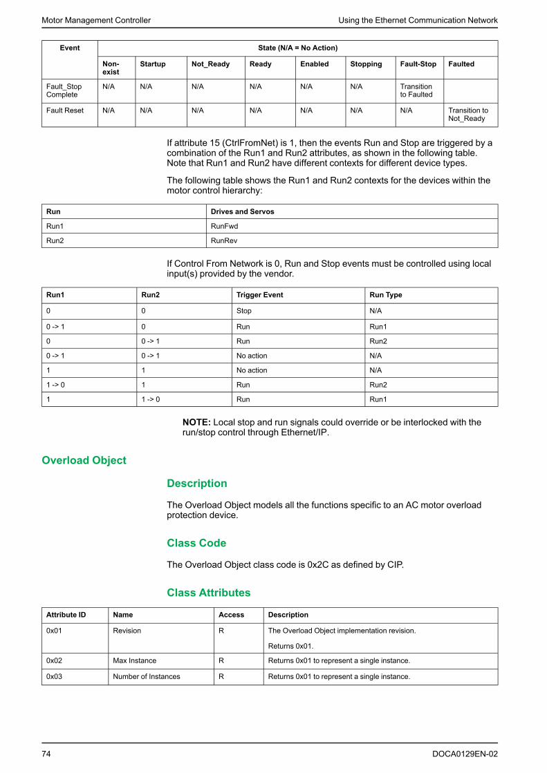
Motor Management Controller Using the Ethernet Communication Network
Event State (N/A = No Action)
Non-exist
Startup Not_Ready Ready Enabled Stopping Fault-Stop Faulted
Fault_StopComplete
N/A N/A N/A N/A N/A N/A Transitionto Faulted
Fault Reset N/A N/A N/A N/A N/A N/A N/A Transition toNot_Ready
If attribute 15 (CtrlFromNet) is 1, then the events Run and Stop are triggered by acombination of the Run1 and Run2 attributes, as shown in the following table.Note that Run1 and Run2 have different contexts for different device types.
The following table shows the Run1 and Run2 contexts for the devices within themotor control hierarchy:
Run Drives and Servos
Run1 RunFwd
Run2 RunRev
If Control From Network is 0, Run and Stop events must be controlled using localinput(s) provided by the vendor.
Run1 Run2 Trigger Event Run Type
0 0 Stop N/A
0 -> 1 0 Run Run1
0 0 -> 1 Run Run2
0 -> 1 0 -> 1 No action N/A
1 1 No action N/A
1 -> 0 1 Run Run2
1 1 -> 0 Run Run1
NOTE: Local stop and run signals could override or be interlocked with therun/stop control through Ethernet/IP.
Overload Object
Description
The Overload Object models all the functions specific to an AC motor overloadprotection device.
Class Code
The Overload Object class code is 0x2C as defined by CIP.
Class Attributes
Attribute ID Name Access Description
0x01 Revision R The Overload Object implementation revision.
Returns 0x01.
0x02 Max Instance R Returns 0x01 to represent a single instance.
0x03 Number of Instances R Returns 0x01 to represent a single instance.
74 DOCA0129EN-02

Using the Ethernet Communication Network Motor Management Controller
Attribute ID Name Access Description
0x06 Max Class Attribute R The largest class attribute value.
Returns 0x07.
0x07 Max Instance Attribute R The largest instance attribute value.
Returns 0xB2.
Class Service
Service Code Name Description
0x0E Get Attribute Single Returns the value of the specified attribute.
Instance Codes
Only one instance is implemented: Instance 1.
Instance Attributes
Attribute ID Name Access Description
0x01 Attribute count R Returns the supported attribute count (46).
0x02 Attribute list R Returns the list of supported instance attributes.
0x03 TripFLCSet R/W % of FLA max
0x04 TripClass R/W Trip Class Setting (5, 10, 15, 20, 25, 30)
0x05 AvgCurrent R 0.1 A
0x06 %PhImbal R % Phase imbalance
0x07 %Thermal R % Thermal capacity
0x08 IL1 Current R 0.1 A
0x09 IL2 Current R 0.1 A
0x0A IL3 Current R 0.1 A
0x0B Ground Current R 0.1 A
0x65 IL1 Current R 0.1 A
0x66 IL2 Current R 0.1 A
0x67 IL3 Current R 0.1 A
0x68 Ground Current R 0.1 A
0x69 IL1 Current Ratio R % of FLC
0x6A IL2 Current Ratio R % of FLC
0x6B IL3 Current Ratio R % of FLC
0x6C IAVAverage Current Ratio R % of FLC
0x6D Thermal Capacity Level R % TripLevel
0x6E Ground Current R 0.1 A
0x6F Current phase imbalance R % Imbalance
0x70 Time to trip R Seconds
0x71 Time to Reset R Seconds
0x7F Single/Three Ph R/W 0 = Single phase
1 = Three phases
0x80 TripFLCSet R/W % of FLA max
0x81 Trip Class R/W Seconds
DOCA0129EN-02 75

Motor Management Controller Using the Ethernet Communication Network
Attribute ID Name Access Description
0x84 Thermal Warn Level R/W % Trip Level
0x85 PL Inhibit Time R/W 0.1 seconds
0x86 PLTrip Delay R/W 0.1 seconds
0x88 GF Trip Delay R/W 0.1...25.0 seconds
0x89 GF Trip Level R/W 20...500% FLC
0x8A GF Warn Level R/W 20...500% FLC
0x8B Stall Enabled Time R/W 1...200 seconds
0x8C Stall Trip Level R/W 100...800 % FLC
0x8E Jam Trip Delay R/W 1...30 seconds
0x8F Jam Trip Level R/W 100...800 % FLC
0x90 Jam Warn Level R/W 100...800 % FLC
0x92 ULTrip Delay R/W 1...200 seconds
0x93 ULTrip Level R/W 30...100 % FLC
0x94 ULWarn Level R/W 30...100 % FLC
0x95 CI Inhibit Time R/W 0.1 seconds
0x96 CI Trip Delay R/W 0.1 seconds
0x97 CI Trip Level R/W 0...70 % Imbalance
0x98 CI Warn Level R/W 0...70 % Imbalance
0xB2 CT Ratio R –
NOTE: In the table above:• PL = Current phase loss• GF = Ground fault• Stall = Long start• UL = Underload• CI = Current phase imbalance
Instance Service
Service Code Name Description
0x0E Get Attribute Single Returns the value of the specified instance attribute.
0x10 Set Attribute Single Sets the value of the specified instance attribute.
Periodically Kept Acyclic Words (PKW) Objects
Overview
The LTMR controller supports PKW (Periodically Kept in acyclicWords). ThePKW feature consists of:• four input words mapped in input assembly objects 111, 112, and 113• four output words mapped in output assembly objects 101, 102, and 103These four words tables enable a EtherNet/IP scanner to read or write anyregister using I/O messaging.
76 DOCA0129EN-02

Using the Ethernet Communication Network Motor Management Controller
As shown in the table below, the PKW area is located at the beginning of thecorresponding assembly objects 112, 113, 102, and 103.
PKW OUT Data
PKW OUT data requests from the EtherNet/IP scanner to the LTMR are mappedin assembly objects 101, 102, and 103.
To access registers, select one of the following function codes:• R_REG_16 (0x25) to read 1 register• R_REG_32 (0x26) to read 2 registers• W_REG_16 (0x2A) to write 1 register• W_REG_32 (0x2B) to write 2 registers
Word 1 Word 2 Word 3 Word 4
MSB LSB
Register address Toggle bit (bit15)
Function bits (bits 8 - 14) Not used (bits0 - 7)
Data to write
Register number 0 / 1 R_REG_16Code 0x25 0x00 – –
R_REG_32Code 0x26 – –
W_REG_16Code 0x2A Data to write inregister
–
W_REG_32Code 0x2B Data to write inregister 1
Data to write inregister 2
Any change in the function code triggers the handling of the request (unlessFunction code [bit 8 to bit 14] = 0x00).
NOTE: The highest bit of function code (bit 15) is a toggle bit. It is changed foreach consecutive request.
This mechanism enables the request initiator to detect that a response isready by polling bit 15 of the function code in word 2. When this bit in the OUTdata becomes equal to the response emitted toggle bit in the IN data (whenstarting the request), then the response is ready.
PKW IN Data
PKW IN data response from the LTMR to the EtherNet/IP scanner are mapped inassembly objects 111, 112, and 113.
The LTMR echoes the same register address and function code or, eventually, anerror code.
DOCA0129EN-02 77

Motor Management Controller Using the Ethernet Communication Network
Word 1 Word 2 Word 3 Word 4
MSB LSB
Register address Toggle bit (bit15)
Function bits (bits 8 - 14) Not used (bits0 - 7)
Data to write
Same register number asin the request
Same as in therequest
ErrorCode 0x4E 0x00 Error code
R_REG_16Code 0x25 – –
R_REG_32Code 0x26 Data read inregister
–
W_REG_16Code 0x2A Data read inregister 1
Data read inregister 2
W_REG_32Code 0x2B – –
If the initiator tries to write a TeSys T object or register to an unauthorized value, ortries to access an inaccessible register, an error code is returned (Function code =toggle bit + 0x4E). The exact error code can be found in words 3 and 4. Therequest is not accepted and the object/register remains at the old value.
To retrigger exactly the same command, you need to:
1. reset the Function code to 0x00,
2. wait for the response frame with the function code equal to 0x00,
3. reset it to its previous value.
This is useful for a limited master like an HMI.
Another way of retriggering exactly the same command is to invert the toggle bit inthe function code byte.
The response is valid when the toggle bit of the response is equal to the toggle bitwritten in the answer (this is a more efficient method, but it requires higherprogramming capabilities).
PKW Error Codes
Case of a write error:
Error Code Error Name Explanation
1 FGP_ERR_REQ_STACK_FULL External request: sends back an error frame
3 FGP_ERR_REGISTER_NOT_FOUND Register not managed (or the request needs super useraccess rights)
4 FGP_ERR_BUSY Too many concurrent requests. Response is delayed.
7 FGP_ERR_INVALID_FUNCTION_OR_ADDRESS Using an undefined PWK function code or read/write toan undefined register address.
8 FGP_ERR_READ_ONLY Register not authorized to be written
10 FGP_ERR_VAL_1WORD_TOOHIGH Written value not in the range of the register (word valueis too high)
11 FGP_ERR_VAL_1WORD_TOOLOW Written value not in the range of the register (word valueis too low)
12 FGP_ERR_VAL_2BYTES_INF_TOOHIGH Written value not in the range of the register (MSB valueis too high)
13 FGP_ERR_VAL_2BYTES_INF_TOOLOW Written value not in the range of the register (MSB valueis too low)
16 FGP_ERR_INVALID_DATA_VALUE Writing to a read-only or reserved register or bit, orwriting a value outside of the valid range.
20 FGP_ERR_BAD_ANSWER External request: sends back an error frame
78 DOCA0129EN-02

Using the Ethernet Communication Network Motor Management Controller
Case of a read error:
Error Code Error Name Explanation
1 FGP_ERR_REQ_STACK_FULL External request: sends back an error frame
3 FGP_ERR_REGISTER_NOT_FOUND Register not managed (or the request needs super useraccess rights)
4 FGP_ERR_ANSWER_DELAYED External request: answer postponed
7 FGP_ERR_NOT_ALL_REGISTER_FOUND One or both registers cannot be found
Class Code
The PKW Object class code is 0xC5, vendor specific definition.
Class Attributes
Attribute ID Name Access Description
0x01 Revision R The PKW Object implementation revision.
Returns 0x01.
0x02 Max instance R Returns 0x01 to represent a single instance.
0x03 Number of instances R The number of object instances.
Returns 0x01.
0x06 Max class attribute R The largest class attribute value.
Returns 0x07.
0x07 Max instance attribute R The largest instance attribute value.
Returns 0x02.
Class Services
Service Code Name Description
0x01 Get attribute all Returns the value of all class attributes.
0x0E Get attribute single Returns the value of the specified attribute.
Instance Codes
Only one instance is implemented: Instance 1.
Instance Attributes
Attribute ID Name Access Description
0x01 Request object R/W Array of eight bytes to represent the PKW request.
0x02 Response object R Array of eight bytes to represent the PKW response.
Instance Services
Service Code Name Description
0x0E Get attribute single Returns the value of the specified instance attribute.
0x10 Set attribute single Modifies the instance attribute value with the access type of R/W.
DOCA0129EN-02 79

Motor Management Controller Using the Ethernet Communication Network
TeSys T Monitoring Control Object
Description
The TeSys T Monitoring Control Object allows selection of four different LTMRinternal data to monitor.
Class Code
The TeSys T Monitoring Control Object class code is 0xC6, vendor specificdefinition.
Class Attributes
Attribute ID Name Access Description
0x01 Revision R The TeSys T Monitoring Control Object implementation revision.
Returns 0x01.
0x02 Max Instance R Returns 0x01 to represent a single instance.
0x03 Number of Instances R The number of object instances.
Returns 0x01.
0x06 Max Class Attribute R The largest class attribute value.
Returns 0x07.
0x07 Max Instance Attribute R The largest instance attribute value.
Returns 0x04.
Class Services
Service Code Name Description
0x01 Get Attribute All Returns the value of all class attributes.
0x0E Get Attribute Single Returns the value of the specified attribute.
Instance Codes
Only one instance is implemented: Instance 1.
Instance Attributes
Attribute ID Name Access Description
0x01 TeSys T Monitoring Word0 Address
R/W UINT type to represent the address of TeSys T Monitoring Word 0.
At power up, it is defaulted to 455.
0x02 TeSys T Monitoring Word1 Address
R/W UINT type to represent the address of TeSys T Monitoring Word 1.
At power up, it is defaulted to 456.
0x03 TeSys T Monitoring Word2 Address
R/W UINT type to represent the address of TeSys T Monitoring Word 2.
At power up, it is defaulted to 457.
0x04 TeSys T Monitoring Word3 Address
R/W UINT type to represent the address of TeSys T Monitoring Word 3.
At power up, it is defaulted to 459.
80 DOCA0129EN-02

Using the Ethernet Communication Network Motor Management Controller
Instance Services
Service Code Name Description
0x10 Set Attribute Single Modifies the instance attribute value with the access type of R/W.
0x0E Get Attribute Single Returns the value of the specified instance attribute.
EtherNet/IP Interface Diagnostic Object
Description
The EtherNet/IP Interface Diagnostic Object enables you to select the data thatwill be exchanged on the network through I/O messaging. A single instance(instance 1) of the EtherNet/IP Interface Object is supported.
Class Code
The EtherNet/IP Interface Diagnostic Object class code is 0x350, vendor specificdefinition.
Class Attributes
Attribute ID Name Access Description
0x01 Revision R The EtherNet/IP Interface Diagnostic Object implementationrevision.
Returns 0x01.
0x02 Max Instance R Returns 0x01 to indicate that there is only one instance.
0x03 Number of Instances R The number of object instances.
Returns 0x01.
0x04 Optional InstanceAttribute List
R Returns 0 to indicate no optional attributes.
0x05 Optional Services List R Returns 0 to indicate no optional services.
0x06 Max Class Attribute R The largest class attribute value.
Returns 0x07.
0x07 Max Instance Attribute R The largest instance attribute value.
Returns 0x04.
Class Services
Service Code Name Description
0x01 Get Attribute All Returns the value of all class attributes.
0x0E Get Attribute Single Returns the value of the specified attribute.
Instance Codes
Only one instance is implemented: Instance 1 for the EtherNet/IP InterfaceDiagnostic object.
Instance Attributes
The following instance attributes are supported:
DOCA0129EN-02 81

Motor Management Controller Using the Ethernet Communication Network
Attribute ID Name Access Description
0x01 Protocols supported Get Protocol(s) supported.
Returns a 16 bit value with bits 0 and 1 set to indicate that EtherNet/IPand Modbus TCP/IP protocols are supported.
0x02 Connection diagnostics Get Returns all the connection diagnostics which includes the followinginformation:• Max CIP I/O Connections opened (UINT): Maximum number of
CIP I/O Connections opened.• Current CIP I/O Connections (UINT): Number of CIP I/O
Connections currently opened.• Max CIP Explicit Connections opened (UINT): Maximum number
of CIP Explicit Connections opened.• Current CIP Explicit Connections (UINT): Number of CIP Explicit
Connections currently opened.• CIP Connections Opening Errors (UINT): Incremented at each
attempt to open a CIP connection that does not succeed.• CIP Connections Timeout Errors (UINT): Incremented when a CIP
connection is timed out.• Max EtherNet IP TCP Connections opened (UINT): Maximum
number of TCP connections opened and used for EtherNet IPcommunication.
• Current EtherNet IP TCP Connections (UINT): Number of TCPconnections currently opened and used for EtherNet IPcommunication.
0x03 I/O Messaging Diagnostics Get/Clear Returns all the I/O messaging diagnostics which includes the followinginformation:• I/O Production Counter (UDINT): Incremented each time a Class
0/1 CIP message is sent.• I/O Consumption Counter (UDINT): Incremented each time a
Class 0/1 CIP message is received.• I/O Production Send Errors Counter (UINT): Incremented each
time a Class 0/1 message is not sent.• I/O Consumption Receive Errors Counter (UINT): Incremented
each time consumption is received with an error.
0x04 Explicit Messaging Diagnostics Get/Clear Returns all the explicit messaging diagnostics which includes thefollowing information:• Class3 Message Send Counter (UDINT): Incremented each time a
Class 3 CIP Message is sent.• Class3 Message Receive Counter (UDINT): Incremented each
time a Class 3 CIP Message is received.• UCMM Message Send Counter (UDINT): Incremented each time
an UCMM Message is sent.• UCMM Message Receive Counter (UDINT): Incremented each
time an UCMM Message is received.
0x05 Communication Capacity Get Returns the communication capacity data which includes the followinginformation:• Max CIP Connections (UINT): Max supported CIP Connections.• Max TCP Connections (UINT): Max supported TCP Connections.• Max Urgent priority rate (UINT): Max CIP transport class 0/1
Urgent priority messages packet(s).• Max Scheduled priority rate (UINT): Max CIP transport class 0/1
Scheduled priority messages Packet(s).• Max High priority rate (UINT): Max CIP transport class 0/1 High
priority messages Packet(s).
82 DOCA0129EN-02

Using the Ethernet Communication Network Motor Management Controller
Attribute ID Name Access Description
0x06 Bandwidth Diagnostics Get Returns the bandwidth diagnostics which includes the followinginformation:• Current sending Urgent priority rate (UINT): CIP transport class 0/1
Urgent priority messages Packet(s) sent.• Current reception Urgent priority rate (UINT): CIP transport class
0/1 Urgent priority messages Packet(s) received.• Current sending Scheduled priority rate (UINT): CIP transport
class 0/1 Scheduled priority messages Packet(s) sent.• Current reception Scheduled priority rate (UINT): CIP transport
class 0/1 Scheduled priority messages Packet(s) received.• Current sending High priority rate (UINT): CIP transport class 0/1
High priority messages Packet(s) sent.• Current sending Low priority rate (UINT): CIP transport class 0/1
Low priority messages Packet(s) sent.• Current reception low priority rate (UINT): CIP transport class 0/1
Low priority messages Packet(s) received.• Current sending Explicit rate (UINT): CIP transport class 2/3 or
other EIP messages Packet(s) sent.• Current reception Explicit rate (UINT): CIP transport class 2/3 or
other EIP messages Packet(s) received.
0x07 Modbus Diagnostic Get Returns the modbus diagnostics which includes the followinginformation:• Max Modbus TCP Connections opened (UINT): Maximum number
of TCP connections opened and used for Modbus communication.• Current Modbus TCP Connections (UINT): Number of TCP
connections currently opened and used for Modbuscommunication.
• Modbus TCP Message Send Counter (UDINT): Incremented eachtime a Modbus TCP/IP Message is sent.
• Modbus TCP Message Receive Counter (UDINT): Incrementedeach time a Modbus TCP/IP Message is received.
Instance Services
Service Code Name Description
0x01 Get Attribute All Returns the value of all instance attributes.
0x0E Get Attribute Single Returns the value of the specified instance attribute.
0x4C Get and Clear Single Returns the value of the specified instance attribute and clears thesame.
I/O Connection Diagnostic Object
Description
The I/O Connection Diagnostic Object provides the detailed diagnostic of eachconfigured CIP I/O connection viewed from a Scanner and of each opened CIP I/O connection viewed from an adapter.
Class Code
The I/O Connection Diagnostic Object class code is 0x352, vendor specificdefinition.
DOCA0129EN-02 83

Motor Management Controller Using the Ethernet Communication Network
Class Attributes
Attribute ID Name Access Description
0x01 Revision Get The I/O Connection Diagnostic Object implementation revision.
Returns 0x01.
0x02 Max Instance Get Returns the maximum instance number created that varies from 0to N (N = maximum number of CIP I/O connections = 32).
0x03 Number of Instances Get Returns the number of instances created that varies from 0 to N (N= maximum number of CIP I/O connections = 32).
0x04 Optional InstanceAttribute List
Get Returns 0 to indicate no optional attributes.
0x05 Optional Services List Get Returns 0 to indicate no optional services.
0x06 Max Class Attribute Get The largest class attribute value.
Returns 0x07.
0x07 Max Instance Attribute Get The largest instance attribute value.
Returns 0x02.
Class Services
Service Code Name Description
0x01 Get Attribute All Returns the value of all class attributes.
0x0E Get Attribute Single Returns the value of the specified attribute.
Instance Codes
The number of instances created varies from 0...N, where N is the maximumnumber of CIP I/O connections.
Instance Attributes
The following instance attributes are supported:
84 DOCA0129EN-02

Using the Ethernet Communication Network Motor Management Controller
Attribute ID Name Access Description
0x01 I/O Communication Diagnostics Get/Clear Returns the I/O communication diagnostics data which contains thefollowing information:• I/O Production Counter(UDINT): Incremented at each production.• I/O Consumption Counter (UDINT): Incremented at each
consumption.• I/O Production Send Errors Counter (UINT): Incremented each
time a production is not sent.• I/O Consumption Receive Errors Counter (UINT): Incremented
each time consumption is received with an error.• CIP Connection Timeout Errors (UINT): Incremented when a
connection is timed out.• CIP Connection Opening Errors (UINT): Incremented at each
attempt to open a connection that does not succeed.• CIP Connection State (UINT): State of the CIP I/O connection.• CIP Last Error General Status (UINT): “General Status” of the last
error detected on the connection.• CIP Last Error Extended Status (UINT): “Extended Status” of the
last error detected on the connection.• Input Com Status (UINT): Communication status of the inputs.• Output Com status (UINT): Communication status of the outputs.
0x02 Connection Diagnostics Get Returns all the connection diagnostics which includes the followinginformation:• Production Connection ID (UDINT): Connection ID for production.• Consumption Connection ID (UDINT): Connection ID for
consumption.• Production RPI (UDINT): RPI for production.• Production API (UDINT): API for production.• Consumption RPI (UDINT): RPI for consumption.• Consumption API (UDINT): API for consumption.• Production Connection Parameters (UDINT): Connection
parameters for production.• Consumption Connection Parameters (UINT): Connection
parameters for consumption.• Local IP (UDINT).• Local UDP Port (UINT).• Remote IP (UDINT).• Remote UDP Port (UINT).• Production Multicast IP (UDINT): Multicast IP used for production.• Consumption Multicast IP (UDINT): Multicast IP used for
consumption.• Protocols supported (UINT): Protocol(s) supported on the
connection.
Instance Services
Service Code Name Description
0x01 Get Attribute All Returns the value of all instance attributes.
0x0E Get Attribute Single Returns the value of the specified instance attribute.
0x4C Get and Clear Single Returns the value of the specified instance attribute and clears thesame.
Explicit Connection Diagnostic Object
Description
The Explicit Connection Diagnostic Object provides a description of an openedExplicit Connection and associated communication.
DOCA0129EN-02 85

Motor Management Controller Using the Ethernet Communication Network
Class Code
The Explicit Connection Diagnostic Object class code is 0x353, vendor specificdefinition.
Class Attributes
Attribute ID Name Access Description
0x01 Revision Get The Explicit Connection Diagnostic Object implementationrevision.
Returns 0x01.
0x02 Max Instance Get Returns the maximum instance number created that varies from 0to N (N = maximum number of CIP explicit connections = 32).
0x03 Number of Instances Get Returns the number of instances created that varies from 0 to N (N= maximum number of CIP explicit connections = 32).
0x04 Optional InstanceAttribute List
Get Returns 0 to indicate no optional attributes.
0x05 Optional Services List Get Returns 0 to indicate no optional services.
0x06 Max Class Attribute Get The largest class attribute value.
Returns 0x07.
0x07 Max Instance Attribute Get The largest instance attribute value.
Returns 0x08.
Class Services
Service Code Name Description
0x01 Get Attribute All Returns the value of all class attributes.
0x0E Get Attribute Single Returns the value of the specified attribute.
Instance Codes
The number of instances created varies from 0...N, where N is the maximumnumber of CIP explicit connections which is 32 at present.
Instance Attributes
The following instance attributes are supported:
Attribute ID Name Access Description
0x01 Originator
Connection ID
Get O -> T Connection ID
0x02 Originator IP Get –
0x03 Originator TCP Port Get –
0x04 Target
Connection ID
Get T -> O Connection ID
0x05 Target IP Get –
0x06 Target TCP Port Get –
0x07 Message Send Counter Get Incremented each time a Class 3 CIP message is sent on theconnection.
0x08 Message Receive Counter Get Incremented each time a Class 3 CIP message is received on theconnection.
86 DOCA0129EN-02

Using the Ethernet Communication Network Motor Management Controller
Instance Services
Service Code Name Description
0x01 Get Attribute All Returns the value of all instance attributes.
Explicit Connection Diagnostic List Object
Description
The Explicit Connection Diagnostic List Object provides a snapshot of the list ofinstantiated Explicit Connection Diagnostic objects.
Class Code
The Explicit Connection Diagnostic List Object class code is 0x354, vendorspecific definition.
Class Attributes
Attribute ID Name Access Description
0x01 Revision Get The Explicit Connection Diagnostic List Object implementationrevision.
Returns 0x01.
0x02 Max Instance Get Returns the maximum instance number created that varies from 0to N (N = maximum number of concurrent list access supported =2).
0x03 Number of Instances Get Returns the number of instances created that varies from 0 to N (N= maximum number of concurrent list access supported = 2).
0x04 Optional InstanceAttribute List
Get Returns 0 to indicate no optional attributes.
0x05 Optional Services List Get Returns 0 to indicate no optional services.
0x06 Max Class Attribute Get The largest class attribute value.
Returns 0x07.
0x07 Max Instance Attribute Get The largest instance attribute value.
Returns 0x02.
Class Services
Service Code Name Description
0x01 Get Attribute All Returns the value of all class attributes.
0x0E Get Attribute Single Returns the value of the specified attribute.
Instance Codes
The number of instances created varies from 0...N, where N is the maximumnumber of concurrent list access supported, which are 2.
Instance Attributes
The following instance attributes are supported:
DOCA0129EN-02 87

Motor Management Controller Using the Ethernet Communication Network
Attribute ID Name Access Description
0x01 Number of Connections Get Total number of opened Explicit connections.
0x02 Explicit MessagingConnections Diagnostic List
Get Array of structures that represents the contents of instantiated “ExplicitConnection Diagnostic” objects.
Each of these objects has the following information:• Originator Connection ID (UDINT): O -> T Connection ID.• Originator IP (UDINT).• Originator TCP Port (UINT).• Target Connection ID (UDINT): T -> O Connection ID.• Target IP (UDINT).• Target TCP Port (UINT).• Message Send Counter (UDINT): Incremented each time a Class
3 CIP message is sent on the connection.• Message Receive Counter (UDINT): Incremented each time a
Class 3 CIP message is received on the connection.
Instance Services
Service Code Name Description
0x08 Create This service creates an instance of the “Explicit Connections DiagnosticList” object.
0x09 Delete This service deletes an instance of the “Explicit Connections DiagnosticList” object.
0x33 Explicit Connections DiagnosticRead
This service reads the explicit connections diagnostics data from the list.
Communication Variables
Overview
This section describes the communication variables for EtherNet/IP and forModbus/TCP communication protocols.
WARNINGLOSS OF CONTROL• The designer of any control scheme must consider the potential failure
modes of control paths and, for certain critical functions, provide a means toachieve a safe state during and after a path failure. Examples of criticalcontrol functions are emergency stop and overtravel stop.
• Separate or redundant control paths must be provided for critical controlfunctions.
• System control paths may include communication links. Consideration mustbe given to the implications of anticipated transmission delays or failures ofthe link.(1)
• Each implementation of an LTMR controller must be individually andthoroughly tested for proper operation before being placed into service.
Failure to follow these instructions can result in death, serious injury, orequipment damage.
(1) For additional information, refer to NEMA ICS 1.1 (latest edition), "SafetyGuidelines for the Application, Installation, and Maintenance of Solid StateControl".
88 DOCA0129EN-02

Using the Ethernet Communication Network Motor Management Controller
WARNINGUNEXPECTED RESTART OF THE MOTOR
Check that the PLC application software:• Considers the change from local to remote control,• Manages the motor control commands appropriately during those changes.When switching to the Network control channel, depending on thecommunication protocol configuration, the LTMR controller can take intoaccount the last known state of the motor control commands issued from thePLC and automatically restart the motor.
Failure to follow these instructions can result in death, serious injury, orequipment damage.
Communication Parameter Clear Commands
Clear Commands Overview
You can clear communication parameters as follows:• Using the LTMR rotary switches to clear its IP addressing settings• Using the following parameter-based commands:◦ Clear all command◦ Clear network port settings command
You can clear other parameters using the following parameter-based commands:• Clear statistics command• Clear thermal capacity level command• Clear controller setting command
Clear IP Using the Rotary Switch
To clear IP addressing settings, set the Ones, or right, rotary switch on the LTMRcontroller to Clear IP (see below):
This clears the following Ethernet parameters:• IP Address• Subnet Mask• GatewayThe position of the Tens, or left, switch does not affect the Clear IP function.
After the IP addressing parameters are cleared, power must be cycled to theLTMR controller for it to obtain new IP addressing parameters, page 28.
DOCA0129EN-02 89

Motor Management Controller Using the Ethernet Communication Network
Clear All Command
If you want to change the configuration of the LTMR controller, you may want toclear all existing parameters in order to set new parameters for the controller.
To clear all parameters, set to 1 the bit 0 of:• Modbus/TCP register address 705• Or EtherNet/IP object address 6C: 01: 06This forces the controller to enter configuration mode. A power-cycle is performedto restart correctly in this mode. This enables the controller to pick up the newvalues for the cleared parameters.
When you clear all parameters, static characteristics are also lost. Only thefollowing parameters are not cleared after a Clear All Command:• Motor LO1 Closings Count• Motor LO2 Closings Count• Controller Internal Temperature Max
Clear Statistics Command
To clear statistics parameters, set to 1 the bit 1 of:• Modbus/TCP register address 705• Or EtherNet/IP object address 6C: 01: 06Statistics parameters are cleared without the LTMR controller being forced intoconfiguration mode. Static characteristics are preserved.
The following parameters are not cleared after a Clear Statistics Command:• Motor LO1 Closings Count• Motor LO2 Closings Count• Controller Internal Temperature Max
Clear Thermal Capacity Level Command
To clear thermal memory parameters, set to 1 the bit 2 of:• Modbus/TCP register address 705• Or EtherNet/IP object address 6C: 01: 06This action clears the following parameters:• Thermal Capacity Level• Rapid Cycle Lockout TimeoutThermal memory parameters are cleared without the LTMR controller being forcedinto configuration mode. Static characteristics are preserved.
NOTE: This bit is writable at any time, even when the motor is running.
Clear Controller Settings Command
The Clear Controller Settings Command restores the LTMR controller protectionfactory setting (timeouts and thresholds).
To clear controller settings parameters, set: to 1 the bit 3 of:• Modbus/TCP register address 705• Or EtherNet/IP object address 6C: 01: 06The following settings are not cleared by this command:• Controller characteristics• Connections (CT, temperature sensor, and I/O settings)• Operating mode
90 DOCA0129EN-02

Using the Ethernet Communication Network Motor Management Controller
Controller setting parameters are cleared without the controller being forced intoconfiguration mode. Static characteristics are preserved.
Clear Network Port Settings Command
The Clear Network Port Settings command restores the network port factorysettings (address, and so on).
To clear controller settings parameters, set to 1 the bit 4 of:• Modbus/TCP register address 705• Or EtherNet/IP object address 6C: 01: 06Controller setting parameters are cleared without the controller being forced intoconfiguration mode. Static characteristics are preserved. Only the networkcommunication becomes ineffective.
After the IP addressing parameters are cleared, power must be cycled to theLTMR controller for it to obtain new IP addressing parameters, page 28.
Simplified Control and Monitoring
Overview
In this section there are two simplified examples of the main registers whichcontrol and monitor a Motor Management Controller, one with Modbus/TCPcommunication protocol and one with EtherNet/IP communication protocol.
DOCA0129EN-02 91

Motor Management Controller Using the Ethernet Communication Network
Modbus/TCP Registers for Simplified Operation
The illustration below provides basic setup information, using the following registers: configuration, control andmonitoring (system status, measurements, faults, and warnings, acknowledgement).
92 DOCA0129EN-02

Using the Ethernet Communication Network Motor Management Controller
EthernNet/IP Registers for Simplified Operation
The illustration below provides basic setup information, using the followingregisters: configuration, control and monitoring (system status, measurements,faults, warnings, and, acknowledgement).
Organization of Communication Variables
Introduction
Communication variables are listed in tables. They belong to groups(identification, statistics, monitoring,...). They are associated with an LTMRcontroller, which may or may not have an LTME expansion module attached.
Communication Variable Groups
Communication variables are grouped according to the following criteria:
Variable Groups Modbus/TCP (RegisterAddresses)
EtherNet/IP (Object Addresses)
Identification variables 00-99 64 : 01 : 32 to 64 : 01 : 61
Statistics variables 100-449 65 : 01 : 01 to 67 : 01 : 83
Monitoring variables 450-539 68 : 01 : 01 to 68 : 01 : 4A
Configuration variables 540-699 69 : 01 : 01 to 6B : 01 : 32
Command variables 700-713 6C : 01 : 01 to 6C : 01 : 0A
DOCA0129EN-02 93

Motor Management Controller Using the Ethernet Communication Network
Variable Groups Modbus/TCP (RegisterAddresses)
EtherNet/IP (Object Addresses)
User map variables 800–999 6D : 01 : 01 to 6E : 01 : 64
Custom logic variables 1250-1399 71 : 01 : 33 to 71 : 01 : C8
Extended monitoring variables for communication 2000-2099 82 : 01 : 01 to 82 : 01 : 27
Mirroring variables 2500-2599 8C : 01 : 01 to 8C : 01 : 15
Extended configuration variables forcommunication
3000-3120 96 : 01 : 01 to 96 : 01 : 77
Table Structure
Communication variables are listed in 5-column tables:
Column 1
Modbus/TCP Registeraddress (in decimal)
Column 2
EtherNet/IP Objectaddress (class :instance : attribute)
Column 3
Variable type: integer,word, word[n], DT_type(see IdentificationVariables, page 102)
Column 4
Variable name and access viaRead only or Read/Writerequests
Column 5
Note: code foradditional information
Note
The Note column gives a code for additional information.
Variables without a code are available for all hardware configurations, and withoutfunctional restrictions.
The code can be:• numerical (1-9), for specific hardware combinations• alphabetical (A-Z), for specific system behaviors
If the Note is... Then the Variable is...
1 available for the LTMR + LTMEV40 combination
2 always available but with a value equal to 0 if no LTMEV40 is connected
3-9 Not used
If the Note is... Then...
A the variable can be written only when the motor is OFF
B the variable can be written only in configuration mode
C the variable can be written only with no fault
D-Z the variable is available for future exceptions
Unused Addresses
Unused addresses fall into three categories:• Not significant, in Read only tables, means that you should ignore the value
read, whether equal to 0 or not.• Reserved, in Read/Write tables, means that you must write 0 in these
variables.• Forbidden, means that read or write requests are rejected, that these
addresses are not accessible at all.
94 DOCA0129EN-02
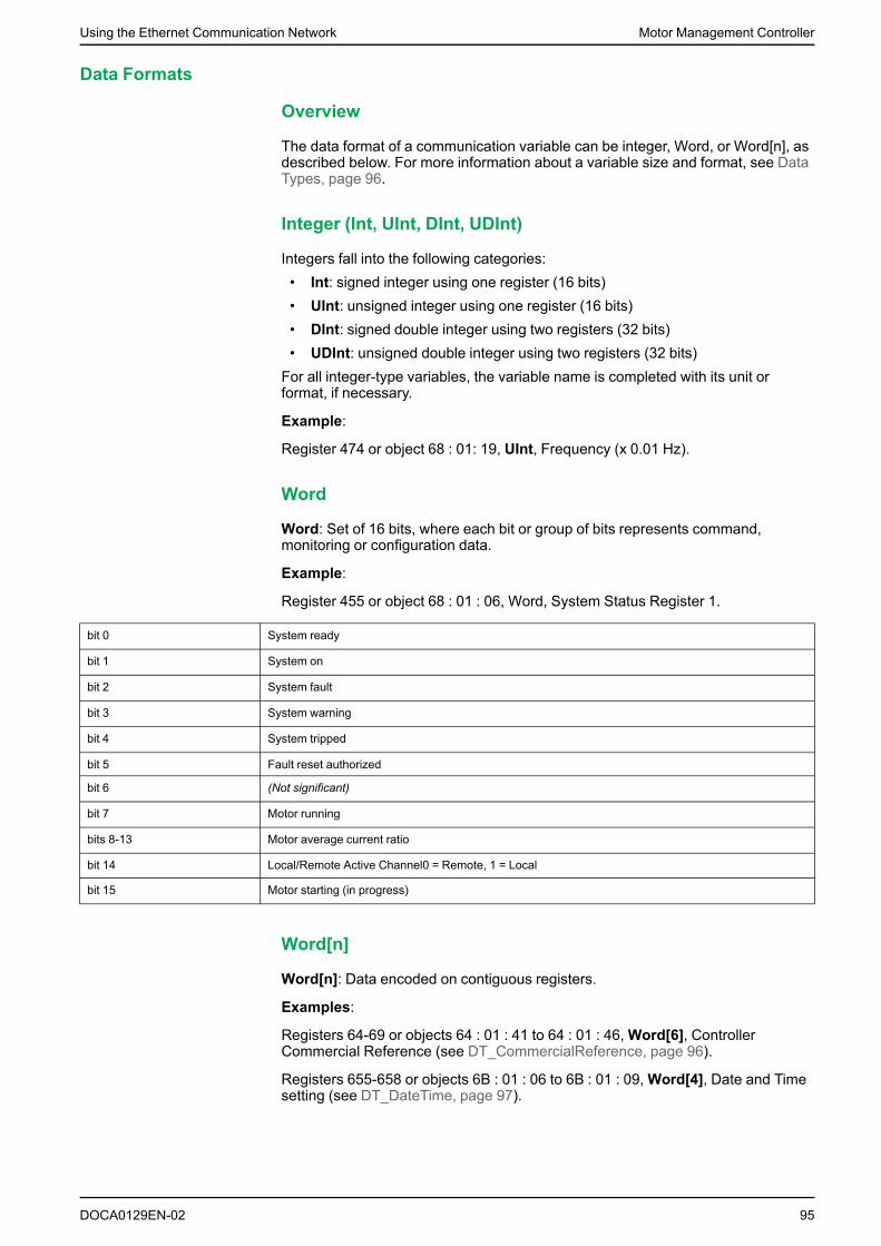
Using the Ethernet Communication Network Motor Management Controller
Data Formats
Overview
The data format of a communication variable can be integer, Word, or Word[n], asdescribed below. For more information about a variable size and format, see DataTypes, page 96.
Integer (Int, UInt, DInt, UDInt)
Integers fall into the following categories:• Int: signed integer using one register (16 bits)• UInt: unsigned integer using one register (16 bits)• DInt: signed double integer using two registers (32 bits)• UDInt: unsigned double integer using two registers (32 bits)For all integer-type variables, the variable name is completed with its unit orformat, if necessary.
Example:
Register 474 or object 68 : 01: 19, UInt, Frequency (x 0.01 Hz).
Word
Word: Set of 16 bits, where each bit or group of bits represents command,monitoring or configuration data.
Example:
Register 455 or object 68 : 01 : 06, Word, System Status Register 1.
bit 0 System ready
bit 1 System on
bit 2 System fault
bit 3 System warning
bit 4 System tripped
bit 5 Fault reset authorized
bit 6 (Not significant)
bit 7 Motor running
bits 8-13 Motor average current ratio
bit 14 Local/Remote Active Channel0 = Remote, 1 = Local
bit 15 Motor starting (in progress)
Word[n]
Word[n]: Data encoded on contiguous registers.
Examples:
Registers 64-69 or objects 64 : 01 : 41 to 64 : 01 : 46,Word[6], ControllerCommercial Reference (see DT_CommercialReference, page 96).
Registers 655-658 or objects 6B : 01 : 06 to 6B : 01 : 09,Word[4], Date and Timesetting (see DT_DateTime, page 97).
DOCA0129EN-02 95

Motor Management Controller Using the Ethernet Communication Network
Data Types
Overview
Data types are specific variable formats which are used to complement thedescription of internal formats (for instance, in case of a structure or of anenumeration). The generic format of data types is DT_xxx.
List of Data Types
Here is the list of the most commonly used data types:• DT_ACInputSetting• DT_CommercialReference• DT_DateTime• DT_ExtBaudRate• DT_ExtParity• DT_EventCode• DT_FirmwareVersion• DT_Language5• DT_OutputFallbackStrategy• DT_PhaseNumber• DT_ResetMode• DT_IndicationCodeThese data types are described below.
DT_ACInputSetting
DT_ACInputSetting format is an enumeration that improves AC input detection:
Value Description
0 None (factory setting)
1 < 170 V 50 Hz
2 < 170 V 60 Hz
3 > 170 V 50 Hz
4 > 170 V 60 Hz
DT_CommercialReference
DT_CommercialReference format isWord[6] and indicates a CommercialReference:
Word MSB LSB
1 character 1 Character 2
2 character 3 Character 4
3 character 5 Character 6
4 character 7 Character 8
5 character 9 Character 10
6 character 11 Character 12
Example:
Registers 64-69 or objects 64 : 01 : 41 to 64 : 01 : 46,Word[6], ControllerCommercial Reference.
96 DOCA0129EN-02

Using the Ethernet Communication Network Motor Management Controller
If Controller Commercial Reference = LTMR:
Modbus/TCP (RegisterAddresses)
EtherNet/IP (Object Addresses) MSB LSB
64 64 : 01 : 41 L T
65 64 : 01 : 42 M (space)
66 64 : 01 : 43 R
67 64 : 01 : 44
68 64 : 01 : 45
69 64 : 01 : 46
DT_DateTime
DT_DateTime format isWord[4] and indicates Date and Time using BinaryCoded Decimal digits:
Word Bits 12-15 Bits 8-11 Bits 4-7 Bits 0-3
1 S S 0 0
2 H H m m
3 M M D D
4 Y Y Y Y
Where:• S = second
The format is two BCD digits.The value range is [00-59] in BCD.
• 0 = unused• H = hour
The format is two BCD digits.The value range is [00-23] in BCD.
• m = minuteThe format is two BCD digits.The value range is [00-59] in BCD.
• M = monthThe format is two BCD digits.The value range is [01-12] in BCD.
• D = dayThe format is two BCD digits.The value range is (in BCD):[01-31] for months 01, 03, 05, 07, 08, 10, and 12[01-30] for months 04, 06, 09, and 11[01-29] for month 02 in a leap year[01-28] for month 02 in a non-leap year.
• Y = yearThe format is four BCD digits.The value range is [2006-2099] in BCD.
DOCA0129EN-02 97

Motor Management Controller Using the Ethernet Communication Network
Data entry format and value range are:
Data Entry Format DT#YYYY-MM-DD-HH:mm:ss
Minimum value DT#2006-01-01:00:00:00 January 1, 2006
Maximum value DT#2099-12-31-23:59:59 December 31, 2099
Note: If you give values outside the limits, the system will return an error.
Example:
Registers 655-658 or objects 6B : 01 : 06 to 6B : 01 : 09,Word[4], Date and Timesetting.
If date is September 4, 2008 at 7 a.m., 50 minutes and 32 seconds:
Modbus/TCP (RegisterAddresses)
EtherNet/IP (ObjectAddresses)
15 12 11 8 7 4 3 0
655 6B : 01 : 06 3 2 0 0
656 6B : 01 : 07 0 7 5 0
657 6B : 01 : 08 0 9 0 4
658 6B : 01 : 09 2 0 0 8
With data entry format: DT#2008-09-04-07:50:32.
DT_ExtBaudRate
DT_ExtbaudRate depends on the bus used:
DT_ModbusExtBaudRate format is an enumeration of possible baud rates withModbus network:
Value Description
1200 1200 Baud
2400 2400 Baud
4800 4800 Baud
9600 9600 Baud
19200 19,200 Baud
65535 Autodetection (factory setting)
DT_ProfibusExtBaudRate format is an enumeration of possible baud rates withPROFIBUS DP network:
Value Description
65535 Autobaud (factory setting)
DT_DeviceNetExtBaudRate format is an enumeration of possible baud rateswith DeviceNet network:
Value Description
0 125 kBaud
1 250 kBaud
2 500 kBaud
3 Autobaud (factory setting)
DT_CANopenExtBaudRate format is an enumeration of possible baud rateswith CANopen network:
98 DOCA0129EN-02

Using the Ethernet Communication Network Motor Management Controller
Value Description
0 10 kBaud
1 20 kBaud
2 50 kBaud
3 125 kBaud
4 250 kBaud (factory setting)
5 500 kBaud
6 800 kBaud
7 1000 kBaud
8 Autobaud
9 Factory setting
DT_ExtParity
DT_ExtParity depends on the bus used:
DT_ModbusExtParity format is an enumeration of possible parities with Modbusnetwork:
Value Description
0 None
1 Even
2 Odd
DT_EventCode
DT_EventCode format is an enumeration of event codes:
Event Code Description
0 No detected error
3 Ground current
4 Thermal overload
5 Long start
6 Jam
7 Current phase imbalance
8 Undercurrent
10 Self test
12 HMI port communication loss
13 Network port internal error
16 External event
20 Overcurrent
21 Current phase loss
22 Current phase reversal
23 Motor temp sensor
24 Voltage phase imbalance
25 Voltage phase loss
26 Voltage phase reversal
27 Undervoltage
28 Overvoltage
DOCA0129EN-02 99

Motor Management Controller Using the Ethernet Communication Network
Event Code Description
29 Underpower
30 Overpower
31 Under power factor
32 Over power factor
33 LTME configuration
34 Temperature sensor short-circuit
35 Temperature sensor open-circuit
36 CT reversal
37 Out of boundary CT ratio
46 Start command check
47 Run check
48 Stop command check
49 Stop check
51 Controller internal temperature error
55 Controller internal detected error (General)
56 Controller internal detected error (SPI)
57 Controller internal detected error (ADC)
58 Controller internal detected error (Hardware watchdog)
60 L2 current detected in single-phase mode
64 Non volatile memory error
65 Expansion module communication error
66 Stuck reset button
67 Logic function error
109 Network port communication loss
111 Fast device replacement error
555 Network port configuration error
DT_FirmwareVersion
DT_FirmwareVersion format is an XY000 array that describes a firmwarerevision:• X = major revision• Y = minor revision.Example:
Register 76 or object 64 : 01 : 4D, UInt, Controller firmware version.
DT_Language5
DT_Language5 format is an enumeration used for language display:
Language Code Description
1 English (factory setting)
2 Français
4 Español
100 DOCA0129EN-02

Using the Ethernet Communication Network Motor Management Controller
Language Code Description
8 Deutsch
16 Italiano
Example:
Register 650 or object 6B : 01 : 01,Word, HMI language.
DT_OutputFallbackStrategy
DT_OutputFallbackStrategy format is an enumeration of motor output stateswhen losing communication.
Value Description Motor Operating Modes
0 Hold LO1 LO2 For all operating modes
1 Run For two-step operating mode only
2 LO1, LO2 OFF For all operating modes
3 LO1, LO2 ON Only for overload, independent and custom operating modes
4 LO1 ON For all operating modes except two-step
5 LO2 ON For all operating modes except two-step
DT_PhaseNumber
DT_PhaseNumber format is an enumeration, with only one bit activated:
Value Description
1 One phase
2 Three phases
DT_ResetMode
DT_ResetMode format is an enumeration of possible modes for event resets:
Value Description
1 Manual or HMI
2 Remote by network
4 Automatic
DT_IndicationCode
DT_IndicationCode format is an enumeration of Indication codes:
Indication Code Description
0 No indication
3 Ground current
4 Thermal overload
5 Long start
6 Jam
7 Current phase imbalance
8 Undercurrent
10 HMI port
DOCA0129EN-02 101

Motor Management Controller Using the Ethernet Communication Network
Indication Code Description
11 LTMR internal temperature
20 Overcurrent
21 Current phase loss
23 Motor temp sensor
24 Voltage phase imbalance
25 Voltage phase loss
27 Undervoltage
28 Overvoltage
29 Underpower
30 Overpower
31 Under power factor
32 Over power factor
33 LTME configuration
34 Temperature sensor short circuit
35 Temperature sensor open circuit
36 CT reversal
46 Start command check
47 Run check
48 Stop command check
49 Stop check
109 Network port comm loss
555 Network port configuration
Identification Variables
Identification Variables
Identification variables are described in the following table:
Modbus/TCP(RegisterAddresses)
EtherNet/IP(Object
Addresses)
VariableType
Read-only Variables Note, page 94
0-34 64 : 01 : 01 -64 : 01 : 23
(Not significant)
35-40 64 : 01 : 24 -64 : 01 : 29
Word[6] Expansion commercial reference
(See DT_CommercialReference, page 96)
1
41-45 64 : 01 : 2A -64 : 01 : 2E
Word[5] Expansion serial number 1
46 64 : 01 : 2F UInt Expansion ID code 1
47 64 : 01 : 30 UInt Expansion firmware version
(See DT_FirmwareVersion, page 100)
1
48 64 : 01 : 31 UInt Expansion compatibility code 1
49-60 64 : 01 : 32 -64 : 01 : 3D
(Not significant)
61 64 : 01 : 3E Ulnt Network port ID code
62 64 : 01 : 3F Ulnt Network port firmware version
(SeeDT_FirmwareVersion, page 100)
102 DOCA0129EN-02

Using the Ethernet Communication Network Motor Management Controller
Modbus/TCP(RegisterAddresses)
EtherNet/IP(Object
Addresses)
VariableType
Read-only Variables Note, page 94
63 64 : 01 : 40 Ulnt Network port compatibility code
64-69 64 : 01 : 41 -64 : 01 : 46
Word[6] Controller commercial reference
(See DT_CommercialReference, page 96)
70-74 64 : 01 : 47 -64 : 01 : 4B
Word[5] Controller serial number
75 64 : 01 : 4C Ulnt Controller ID code
76 64 : 01 : 4D Ulnt Controller firmware version
(SeeDT_FirmwareVersion, page 100)
77 64 : 01 : 4E Ulnt Controller compatibility code
78 64 : 01 : 4F Ulnt Current scale ratio (0.1 %)
79 64 : 01 : 50 Ulnt Current sensor max
80 64 : 01 : 51 (Not significant)
81 64 : 01 : 52 Ulnt Current range max (x 0.1 A)
82-94 64 : 01 : 53 -64 : 01 : 5F
(Not significant)
95 64 : 01 : 60 Ulnt Load CT ratio (x 0.1 A)
96 64 : 01 : 61 Ulnt Full load current max (maximum FLC range, FLC = Full LoadCurrent) (x 0.1 A)
97-99 64 : 01 : 62 -64 : 01 : 64
(Forbidden)
Statistics Variables
Statistics Overview
Statistics variables are grouped according to the following criteria. Trip statisticsare contained into a main table and an extension table.
Statistics Variable Groups Modbus/TCP (Register Addresses) EtherNet/IP (Object Addresses)
Global statistics 100-121 65 : 01 : 01 - 65 : 01 : 16
LTMR monitoring statistics 122-149 65 : 01 : 17 - 65 : 01 : 32
Last trip statistics
and extension
150-179
300-309
66 : 01 : 01 - 66 : 01 : 1E
67 : 01 : 01 - 67 : 01 : 0A
Trip n-1 statistics
and extension
180-209
330-339
66 : 01 : 1F - 66 : 01 : 3C
67 : 01 : 1F - 67 : 01 : 28
Trip n-2 statistics
and extension
210-239
360-369
66 : 01 : 3D - 66 : 01 : 5A
67 : 01 : 3D - 67 : 01 : 46
Trip n-3 statistics
and extension
240-269
390-399
66 : 01 : 5B - 66 : 01 : 78
67 : 01 : 5B - 67 : 01 : 64
Trip n-4 statistics
and extension
270-299
420-429
66 : 01 : 79 - 66 : 01 : 96
67 : 01 : 79 - 67 : 01 : 82
Global Statistics
The global statistics are described in the following table:
DOCA0129EN-02 103

Motor Management Controller Using the Ethernet Communication Network
Modbus/TCP(RegisterAddresses)
EtherNet/IP (ObjectAddresses)
VariableType
Read-only Variables Note, page 94
100-101 65 : 01 : 01 - 65 : 01 :02
(Not significant)
102 65 : 01 : 03 Ulnt Ground current faults count
103 65 : 01 : 04 Ulnt Thermal overload faults count
104 65 : 01 : 05 Ulnt Long start faults count
105 65 : 01 : 06 Ulnt Jam faults count
106 65 : 01 : 07 Ulnt Current phase imbalance faults count
107 65 : 01 : 08 Ulnt Undercurrent faults count
108 65 : 01 : 09 Uint desc = (Not significant)
109 65 : 01 : 0A Ulnt HMI port faults count
110 65 : 01 : 0B Ulnt Controller internal faults count
111 65 : 01 : 0C Ulnt Internal port faults count
112 65 : 01 : 0D Ulnt (Not significant)
113 65 : 01 : 0E Ulnt Network port config faults count
114 65 : 01 : 0F Ulnt Network port faults count
115 65 : 01 : 10 Ulnt Auto-resets count
116 65 : 01 : 11 Ulnt Thermal overload warnings count
117-118 65 : 01 : 12 - 65 : 01 :13
UDlnt Motor starts count
119-120 65 : 01 : 14 - 65 : 01 :15
UDlnt Operating time (s)
121 65 : 01 : 16 lnt Controller internal temperature max (°C)
LTMR Monitoring Statistics
The LTMR monitoring statistics are described below:
Modbus/TCP(RegisterAddresses)
EtherNet/IP (ObjectAddresses)
VariableType
Read-only Variables Note, page 94
122 65 : 01 : 17 Ulnt Faults count
123 65 : 01 : 18 Ulnt Warnings count
124-125 65 : 01 : 19 - 65 : 01 :1A
UDlnt Motor LO1 closings count
126-127 65 : 01 : 1B - 65 : 01 :1C
UDlnt Motor LO2 closings count
128 65 : 01 : 1D Ulnt Diagnostic faults count
129 65 : 01 : 1E Ulnt (Reserved)
130 65 : 01 : 1F Ulnt Overcurrent faults count
131 65 : 01 : 20 Ulnt Current phase loss faults count
132 65 : 01 : 21 Ulnt Motor temperature sensor faults count
133 65 : 01 : 22 Ulnt Voltage phase imbalance faults count 1
134 65 : 01 : 23 Ulnt Voltage phase loss faults count 1
135 65 : 01 : 24 Ulnt Wiring faults count 1
136 65 : 01 : 25 Ulnt Undervoltage faults count 1
137 65 : 01 : 26 Ulnt Overvoltage faults count 1
138 65 : 01 : 27 Ulnt Underpower faults count 1
104 DOCA0129EN-02

Using the Ethernet Communication Network Motor Management Controller
Modbus/TCP(RegisterAddresses)
EtherNet/IP (ObjectAddresses)
VariableType
Read-only Variables Note, page 94
139 65 : 01 : 28 Ulnt Overpower faults count 1
140 65 : 01 : 29 Ulnt Under power factor faults count 1
141 65 : 01 : 2A Ulnt Over power factor faults count 1
142 65 : 01 : 2B Ulnt Load sheddings count 1
143-144 65 : 01 : 2C - 65 : 01 :2D
UDlnt Active power consumption (kWh) 1
145-146 65 : 01 : 2E - 65 : 01 :2F
UDlnt Reactive power consumption (kVARh) 1
147 65 : 01 : 30 Ulnt Auto restart immediate count
148 65 : 01 : 31 Ulnt Auto restart delayed count
149 65 : 01 : 32 Ulnt Auto restart manual count
Last Fault (n-0) Statistics
The last fault statistics are completed by variables at register addresses 300 to310.
Modbus/TCP(RegisterAddresses)
EtherNet/IP (ObjectAddresses)
VariableType
Read-only Variables Note, page 94
150 66 : 01 : 01 Ulnt Fault code n-0
151 66 : 01 : 02 Ulnt Motor full load current ratio n-0 (% FLC max)
152 66 : 01 : 03 Ulnt Thermal capacity level n-0 (% trip level)
153 66 : 01 : 04 Ulnt Average current ratio n-0 (% FLC)
154 66 : 01 : 05 Ulnt L1 current ratio n-0 (% FLC)
155 66 : 01 : 06 Ulnt L2 current ratio n-0 (% FLC)
156 66 : 01 : 07 Ulnt L3 current ratio n-0 (% FLC)
157 66 : 01 : 08 Ulnt Ground current ratio n-0 (x 0.1 % FLC min)
158 66 : 01 : 09 Ulnt Full load current max n-0 (x 0.1 A)
159 66 : 01 : 0A Ulnt Current phase imbalance n-0 (%)
160 66 : 01 : 0B Ulnt Frequency n-0 (x 0.1 Hz)
161 66 : 01 : 0C Ulnt Motor temperature sensor n-0 (x 0.1 Ω)
162-165 66 : 01 : OD - 66 : 01 :10
Word[4] Date and time n-0
(See DT_DateTime, page 97)
166 66 : 01 : 11 Ulnt Average voltage n-0 (V) 1
167 66 : 01 : 12 Ulnt L3-L1 voltage n-0 (V) 1
168 66 : 01 : 13 Ulnt L1-L2 voltage n-0 (V) 1
169 66 : 01 : 14 Ulnt L2-L3 voltage n-0 (V) 1
170 66 : 01 : 15 Ulnt Voltage phase imbalance n-0 (%) 1
171 66 : 01 : 16 Ulnt Active power n-0 (x 0.1 kW) 1
172 66 : 01 : 17 Ulnt Power factor n-0 (x 0.01) 1
173-179 66 : 01 : 18 - 66 : 01 :1E
(Not significant)
DOCA0129EN-02 105

Motor Management Controller Using the Ethernet Communication Network
N-1 Fault Statistics
The n-1 fault statistics are completed by variables at register addresses 330 to340.
Modbus/TCP(RegisterAddresses)
EtherNet/IP (ObjectAddresses)
VariableType
Read-only Variables Note, page 94
180 66 : 01 : 1F Ulnt Fault code n-1
181 66 : 01 : 20 Ulnt Motor full load current ratio n-1 (% FLC max)
182 66 : 01 : 21 Ulnt Thermal capacity level n-1 (% trip level)
183 66 : 01 : 22 Ulnt Average current ratio n-1 (% FLC)
184 66 : 01 : 23 Ulnt L1 current ratio n-1 (% FLC)
185 66 : 01 : 24 Ulnt L2 current ratio n-1 (% FLC)
186 66 : 01 : 25 Ulnt L3 current ratio n-1 (% FLC)
187 66 : 01 : 26 Ulnt Ground current ratio n-1 (x 0.1 % FLC min)
188 66 : 01 : 27 Ulnt Full load current max n-1 (x 0.1 A)
189 66 : 01 : 28 Ulnt Current phase imbalance n-1 (%)
190 66 : 01 : 29 Ulnt Frequency n-1 (x 0.1 Hz)
191 66 : 01 : 2A Ulnt Motor temperature sensor n-1 (x 0.1 Ω)
192-195 66 : 01 : 2B - 66 : 01 :2E
Word[4] Date and time n-1
(See DT_DateTime, page 97)
196 66 : 01 : 2F Ulnt Average voltage n-1 (V) 1
197 66 : 01 : 30 Ulnt L3-L1 voltage n-1 (V) 1
198 66 : 01 : 31 Ulnt L1-L2 voltage n-1 (V) 1
199 66 : 01 : 32 Ulnt L2-L3 voltage n-1 (V) 1
200 66 : 01 : 33 Ulnt Voltage phase imbalance n-1 (%) 1
201 66 : 01 : 34 Ulnt Active power n-1 (x 0.1 kW) 1
202 66 : 01 : 35 Ulnt Power factor n-1 (x 0.01) 1
203-209 66 : 01 : 36 - 66 : 01 :3C
Ulnt (Not significant)
N-2 Fault Statistics
The n-2 fault statistics are completed by variables at register addresses 360 to370.
Modbus/TCP(RegisterAddresses)
EtherNet/IP (ObjectAddresses)
VariableType
Read-only Variables Note, page 94
210 66 : 01 : 3D Ulnt Fault code n-2
211 66 : 01 : 3E Ulnt Motor full load current ratio n-2 (% FLC max)
212 66 : 01 : 3F Ulnt Thermal capacity level n-2 (% trip level)
213 66 : 01 : 40 Ulnt Average current ratio n-2 (% FLC)
214 66 : 01 : 41 Ulnt L1 current ratio n-2 (% FLC)
215 66 : 01 : 42 Ulnt L2 current ratio n-2 (% FLC)
216 66 : 01 : 43 Ulnt L3 current ratio n-2 (% FLC)
217 66 : 01 : 44 Ulnt Ground current ratio n-2 (x 0.1 % FLC min)
218 66 : 01 : 45 Ulnt Full load current max n-2 (x 0.1 A)
106 DOCA0129EN-02

Using the Ethernet Communication Network Motor Management Controller
Modbus/TCP(RegisterAddresses)
EtherNet/IP (ObjectAddresses)
VariableType
Read-only Variables Note, page 94
219 66 : 01 : 46 Ulnt Current phase imbalance n-2 (%)
220 66 : 01 : 47 Ulnt Frequency n-2 (x 0.1 Hz)
221 66 : 01 : 48 Ulnt Motor temperature sensor n-2 (x 0.1 Ω)
222-225 66 : 01 : 49 - 66 : 01 :4C
Word[4] Date and time n-2
(See DT_DateTime, page 97)
226 66 : 01 : 4D Ulnt Average voltage n-2 (V) 1
227 66 : 01 : 4E Ulnt L3-L1 voltage n-2 (V) 1
228 66 : 01 : 4F Ulnt L1-L2 voltage n-2 (V) 1
229 66 : 01 : 50 Ulnt L2-L3 voltage n-2 (V) 1
230 66 : 01 : 51 Ulnt Voltage phase imbalance n-2 (%) 1
231 66 : 01 : 52 Ulnt Active power n-2 (x 0.1 kW) 1
232 66 : 01 : 53 Ulnt Power factor n-2 (x 0.01) 1
233-239 66 : 01 : 54 - 66 : 01 :5A
(Not significant)
N-3 Fault Statistics
The n-3 fault statistics are completed by variables at register addresses 390 to400.
Modbus/TCP(RegisterAddresses)
EtherNet/IP (ObjectAddresses)
VariableType
Read-only Variables Note, page 94
240 66 : 01 : 5B Ulnt Fault code n-3
241 66 : 01 : 5C Ulnt Motor full load current ratio n-3 (% FLC max)
242 66 : 01 : 5D Ulnt Thermal capacity level n-3 (% trip level)
243 66 : 01 : 5E Ulnt Average current ratio n-3 (% FLC)
244 66 : 01 : 5F Ulnt L1 current ratio n-3 (% FLC)
245 66 : 01 : 60 Ulnt L2 current ratio n-3 (% FLC)
246 66 : 01 : 61 Ulnt L3 current ratio n-3 (% FLC)
247 66 : 01 : 62 Ulnt Ground current ratio n-3 (x 0.1 % FLC min)
248 66 : 01 : 63 Ulnt Full load current max n-3 (0.1 A)
249 66 : 01 : 64 Ulnt Current phase imbalance n-3 (%)
250 66 : 01 : 65 Ulnt Frequency n-3 (x 0.1 Hz)
251 66 : 01 : 66 Ulnt Motor temperature sensor n-3 (x 0.1 Ω)
252-255 66 : 01 : 67 -66 : 01 :6A
Word[4] Date and time n-3
(See DT_DateTime, page 97)
256 66 : 01 : 6B Ulnt Average voltage n-3 (V) 1
257 66 : 01 : 6C Ulnt L3-L1 voltage n-3 (V) 1
258 66 : 01 : 6D Ulnt L1-L2 voltage n-3 (V) 1
259 66 : 01 : 6E Ulnt L2-L3 voltage n-3 (V) 1
260 66 : 01 : 6F Ulnt Voltage phase imbalance n-3 (%) 1
261 66 : 01 : 70 Ulnt Active power n-3 (x 0.1 kW) 1
DOCA0129EN-02 107

Motor Management Controller Using the Ethernet Communication Network
Modbus/TCP(RegisterAddresses)
EtherNet/IP (ObjectAddresses)
VariableType
Read-only Variables Note, page 94
262 66 : 01 : 71 Ulnt Power factor n-3 (x 0.01) 1
263-269 66 : 01 : 72 - 66 : 01 :78
(Not significant)
N-4 Fault Statistics
The n-4 fault statistics are completed by variables at register addresses 420 to430.
Modbus/TCP(RegisterAddresses)
EtherNet/IP (ObjectAddresses)
VariableType
Read-only Variables Note, page 94
270 66 : 01 : 79 Ulnt Fault code n-4
271 66 : 01 : 7A Ulnt Motor full load current ratio n-4 (% FLC max)
272 66 : 01 : 7B Ulnt Thermal capacity level n-4 (% trip level)
273 66 : 01 : 7C Ulnt Average current ratio n-4 (% FLC)
274 66 : 01 : 7D Ulnt L1 current ratio n-4 (% FLC)
275 66 : 01 : 7E Ulnt L2 current ratio n-4 (% FLC)
276 66 : 01 : 7F Ulnt L3 current ratio n-4 (% FLC)
277 66 : 01 : 80 Ulnt Ground current ratio n-4 (x 0.1 % FLC min)
278 66 : 01 : 81 Ulnt Full load current max n-4 (x 0.1 A)
279 66 : 01 : 82 Ulnt Current phase imbalance n-4 (%)
280 66 : 01 : 83 Ulnt Frequency n-4 (x 0.1 Hz)
281 66 : 01 : 84 Ulnt Motor temperature sensor n-4 (x 0.1 Ω)
282-285 66 : 01 : 85 - 66 : 01 :88
Word[4] Date and time n-4
(See DT_DateTime, page 97)
286 66 : 01 : 89 Ulnt Average voltage n-4 (V) 1
287 66 : 01 : 8A Ulnt L3-L1 voltage n-4 (V) 1
288 66 : 01 : 8B Ulnt L1-L2 voltage n-4 (V) 1
289 66 : 01 : 8C Ulnt L2-L3 voltage n-4 (V) 1
290 66 : 01 : 8D Ulnt Voltage phase imbalance n-4 (%) 1
291 66 : 01 : 8E Ulnt Active power n-4 (x 0.1 kW) 1
292 66 : 01 : 8F Ulnt Power factor n-4 (x 0.01) 1
293-299 66 : 01 : 90 - 66 : 01 :96
(Not significant)
Last Fault (n-0) Statistics Extension
The last fault main statistics are listed at register addresses 150 to 179.
Modbus/TCP(RegisterAddresses)
EtherNet/IP (ObjectAddresses)
VariableType
Read-only Variables Note, page 94
300-301 67 : 01 : 01 - 67 : 01 :02
UDlnt Average current n-0 (x 0.01 A)
302-303 67 : 01 : 03 - 67 : 01 :04
UDlnt L1 current n-0 (x 0.01 A)
304-305 67 : 01 : 05 - 67 : 01 :06
UDlnt L2 current n-0 (x 0.01 A)
108 DOCA0129EN-02

Using the Ethernet Communication Network Motor Management Controller
Modbus/TCP(RegisterAddresses)
EtherNet/IP (ObjectAddresses)
VariableType
Read-only Variables Note, page 94
306-307 67 : 01 : 07 - 67 : 01 :08
UDlnt L3 current n-0 (x 0.01 A)
308-309 67 : 01 : 09 - 67 : 01 :0A
UDlnt Ground current n-0 (mA)
310 67 : 01 : 0B Ulnt Motor temperature sensor degree n-0 (°C)
N-1 Fault Statistics Extension
The n-1 fault main statistics are listed at register addresses 180 to 209.
Modbus/TCP(RegisterAddresses)
EtherNet/IP (ObjectAddresses)
VariableType
Read-only Variables Note, page 94
330-331 67 : 01 : 1F - 67 : 01 :20
UDlnt Average current n-1 (x 0.01 A)
332-333 67 : 01 : 21 - 67 : 01 :22
UDlnt L1 current n-1 (x 0.01 A)
334-335 67 : 01 : 23 - 67 : 01 :24
UDlnt L2 current n-1 (x 0.01 A)
336-337 67 : 01 : 25 - 67 : 01 :26
UDlnt L3 current n-1 (x 0.01 A)
338-339 67 : 01 : 27 - 67 : 01 :28
UDlnt Ground current n-1 (mA)
340 67 : 01 : 29 Ulnt Motor temperature sensor degree n-1 (°C)
N-2 Fault Statistics Extension
The n-2 fault main statistics are listed at register addresses 210 to 239.
Modbus/TCP(RegisterAddresses)
EtherNet/IP (ObjectAddresses)
VariableType
Read-only Variables Note, page 94
360-361 67 : 01 : 3D - 67 : 01 :3E
UDlnt Average current n-2 (x 0.01 A)
362-363 67 : 01 : 3F - 67 : 01 :40
UDlnt L1 current n-2 (x 0.01 A)
364-365 67 : 01 : 41 - 67 : 01 :42
UDlnt L2 current n-2 (x 0.01 A)
366-367 67 : 01 : 43 - 67 : 01 :44
UDlnt L3 current n-2 (x 0.01 A)
368-369 67 : 01 : 45 - 67 : 01 :46
UDlnt Ground current n-2 (mA)
370 67 : 01 : 47 Ulnt Motor temperature sensor degree n-2 (°C)
N-3 Fault Statistics Extension
The n-3 fault main statistics are listed at register addresses 240 to 269.
Modbus/TCP(RegisterAddresses)
EtherNet/IP (ObjectAddresses)
VariableType
Read-only Variables Note, page 94
390-391 67 : 01 : 5B - 67 : 01 :5C
UDlnt Average current n-3 (x 0.01 A)
392-393 67 : 01 : 5D - 67 : 01 :5E
UDlnt L1 current n-3 (x 0.01 A)
DOCA0129EN-02 109

Motor Management Controller Using the Ethernet Communication Network
Modbus/TCP(RegisterAddresses)
EtherNet/IP (ObjectAddresses)
VariableType
Read-only Variables Note, page 94
394-395 67 : 01 : 5F - 67 : 01 :60
UDlnt L2 current n-3 (x 0.01 A)
396-397 67 : 01 : 61 - 67 : 01 :62
UDlnt L3 current n-3 (x 0.01 A)
398-399 67 : 01 : 63 - 67 : 01 :64
UDlnt Ground current n-3 (mA)
400 67 : 01 : 65 Ulnt Motor temperature sensor degree n-3 (°C)
N-4 Fault Statistics Extension
The n-4 fault main statistics are listed at register addresses 270 to 299.
Modbus/TCP(RegisterAddresses)
EtherNet/IP (ObjectAddresses)
VariableType
Read-only Variables Note, page 94
420-421 67 : 01 : 79 - 67 : 01 :7A
UDlnt Average current n-4 (x 0.01 A)
422-423 67 : 01 : 7B - 67 : 01 :7C
UDlnt L1 current n-4 (x 0.01 A)
424-425 67 : 01 : 7D - 67 : 01 :7E
UDlnt L2 current n-4 (x 0.01 A)
426-427 67 : 01 : 7F - 67 : 01 :80
UDlnt L3 current n-4 (x 0.01 A)
428-429 67 : 01 : 81 - 67 : 01 :82
UDlnt Ground current n-4 (mA)
430 67 : 01 : 83 Ulnt Motor temperature sensor degree n-4 (°C)
Monitoring Variables
Monitoring Overview
Monitoring variables are grouped according to the following criteria:
Monitoring Variable groups Modbus/TCP (RegisterAddresses)
EtherNet/IP (Object Addresses)
Monitoring of faults 450-454 68 : 01 : 01 to 68 : 01 : 05
Monitoring of status 455-459 68 : 01 : 06 to 68 : 01 : 0A
Monitoring of warnings 460-464 68 : 01 : 0B to 68 : 01 : 0F
Monitoring of measurements 465-539 68 : 01 : 10 to 68 : 01 : 5A
Extended monitoring for communication 2000-2099 82 : 01 : 01 to 82 : 01 : 64
Monitoring of Faults
Variables for monitoring of faults are described in the following table:
Modbus/TCP(RegisterAddresses)
EtherNet/IP(Object
Addresses)
VariableType
Read-only Variables Note, page 94
450 68 : 01 : 01 Ulnt Minimum wait time (s)
451 68 : 01 : 02 Ulnt Fault code (code of the last fault, or of the fault that takespriority)
(See DT_EventCode, page 99.)
110 DOCA0129EN-02

Using the Ethernet Communication Network Motor Management Controller
Modbus/TCP(RegisterAddresses)
EtherNet/IP(Object
Addresses)
VariableType
Read-only Variables Note, page 94
452 68 : 01 : 03 Word Fault register 1
bits 0-1 (Reserved)
bit 2 Ground current fault
bit 3 Thermal overload fault
bit 4 Long start fault
bit 5 Jam fault
bit 6 Current phase imbalance fault
bit 7 Undercurrent fault
bit 8 (Reserved)
bit 9 Test fault
bit 10 HMI port fault
bit 11 Controller internal fault
bit 12 Internal port fault
bit 13 (Not significant)
bit 14 Network port config fault
bit 15 Network port fault
453 68 : 01 : 04 Word Fault register 2
bit 0 External system fault
bit 1 Diagnostic fault
bit 2 Wiring fault
bit 3 Overcurrent fault
bit 4 Current phase loss fault
bit 5 Current phase reversal fault
bit 6 Motor temperature sensor fault 1
bit 7 Voltage phase imbalance fault 1
bit 8 Voltage phase loss fault 1
bit 9 Voltage phase reversal fault 1
bit 10 Undervoltage fault 1
bit 11 Overvoltage fault 1
bit 12 Underpower fault 1
bit 13 Overpower fault 1
bit 14 Under power factor fault 1
bit 15 Over power factor fault 1
454 68 : 01 : 05 Word Fault register 3
bit 0 LTME configuration fault
bit 1 = LTMR configuration fault
bits 2-15 (Reserved)
Monitoring of Status
Variables for monitoring of status are described below:
DOCA0129EN-02 111

Motor Management Controller Using the Ethernet Communication Network
Modbus/TCP(RegisterAddresses)
EtherNet/IP(Object
Addresses)
VariableType
Read-only Variables Note, page 94
455 68 : 01 : 06 Word System status register 1
bit 0 System ready
bit 1 System on
bit 2 System fault
bit 3 System warning
bit 4 System tripped
bit 5 fault reset authorized
bit 6 Controller power
bit 7 Motor running (with detection of a current, if greaterthan 10% FLC)
bits 8-13 Motor average current ratio
32 = 100% FLC - 63 = 200% FLC
bit 14 Local/Remote Active Channel0 = Remote, 1 = Local
bit 15 Motor starting (start in progress)
0 = descending current is less than 150% FLC
1 = ascending current is greater than 10% FLC
456 68 : 01 : 07 Word System status register 2
bit 0 Auto-reset active
bit 1 (Not significant)
bit 2 fault power cycle requested
bit 3 Motor restart time undefined
bit 4 Rapid cycle lockout
bit 5 Load shedding 1
bit 6 Motor speed
0 = FLC1 setting is used
1 = FLC2 setting is used
bit 7 HMI port comm loss
bit 8 Network port comm loss
bit 9 Motor transition lockout
bits 10-15 (Not significant)
457 68 : 01 : 08 Word Logic inputs status
bit 0 Logic input 1
bit 1 Logic input 2
bit 2 Logic input 3
bit 3 Logic input 4
bit 4 Logic input 5
bit 5 Logic input 6
bit 6 Logic input 7
bit 7 Logic input 8 1
bit 8 Logic input 9 1
bit 9 Logic input 10 1
bit 10 Logic input 11 1
112 DOCA0129EN-02

Using the Ethernet Communication Network Motor Management Controller
Modbus/TCP(RegisterAddresses)
EtherNet/IP(Object
Addresses)
VariableType
Read-only Variables Note, page 94
bit 11 Logic input 12 1
bit 12 Logic input 13 1
bit 13 Logic input 14 1
bit 14 Logic input 15 1
bit 15 Logic input 16 1
458 68 : 01 : 09 Word Logic outputs status
bit 0 Logic output 1
bit 1 Logic output 2
bit 2 Logic output 3
bit 3 Logic output 4
bit 4 Logic output 5 1
bit 5 Logic output 6 1
bit 6 Logic output 7 1
bit 7 Logic output 8 1
bits 8-15 (Reserved)
459 68 : 01 : 0A Word I/O status
bit 0 Input 1
bit 1 Input 2
bit 2 Input 3
bit 3 Input 4
bit 4 Input 5
bit 5 Input 6
bit 6 Input 7
bit 7 Input 8
bit 8 Input 9
bit 9 Input 10
bit 10 Input 11
bit 11 Input 12
bit 12 Output 1 (13-14)
bit 13 Output 2 (23-24)
bit 14 Output 3 (33-34)
bit 15 Output 4 (95-96, 97-98)
Monitoring of Warnings
Variables for monitoring of warnings are described in the following table:
Modbus/TCP(RegisterAddresses)
EtherNet/IP(Object
Addresses)
VariableType
Read-only Variables Note, page 94
460 68 : 01 : 0B UInt Warning code
(See DT_IndicationCode, page 101.)
461 68 : 01 : 0C Word Warning register 1
DOCA0129EN-02 113

Motor Management Controller Using the Ethernet Communication Network
Modbus/TCP(RegisterAddresses)
EtherNet/IP(Object
Addresses)
VariableType
Read-only Variables Note, page 94
bits 0-1 (Not significant)
bit 2 Ground current warning
bit 3 Thermal overload warning
bit 4 (Not significant)
bit 5 Jam warning
bit 6 Current phase imbalance warning
bit 7 Undercurrent warning
bits 8-9 (Not significant)
bit 10 HMI port warning
bit 11 Controller internal temperature warning
bits 12-14 (Not significant)
bit 15 Network port warning
462 68 : 01 : 0D Word Warning register 2
bit 0 (Not significant)
bit 1 Diagnostic warning
bit 2 (Not significant)
bit 3 Overcurrent warning
bit 4 Current phase loss warning
bit 5 Current phase reversal warning
bit 6 Motor temperature sensor warning
bit 7 Voltage phase imbalance warning 1
bit 8 Voltage phase loss warning 1
bit 9 (Not significant)
bit 10 Undervoltage warning 1
bit 11 Overvoltage warning 1
bit 12 Underpower warning 1
bit 13 Overpower warning 1
bit 14 Under power factor warning 1
bit 15 Over power factor warning 1
463 68 : 01 : 0E Word Warning register 3
bit 0 LTME configuration warning
bits 1-15 (Reserved)
464 68 : 01 : 0F Ulnt Motor temperature sensor degree (°C)
Monitoring of Measurements
Variables for monitoring of measurements are described below:
Modbus/TCP(RegisterAddresses)
EtherNet/IP(Object
Addresses)
VariableType
Read-only Variables Note, page 94
465 68 : 01 : 10 UInt Thermal capacity level (% trip level)
466 68 : 01 : 11 UInt Average current ratio (% FLC)
114 DOCA0129EN-02

Using the Ethernet Communication Network Motor Management Controller
Modbus/TCP(RegisterAddresses)
EtherNet/IP(Object
Addresses)
VariableType
Read-only Variables Note, page 94
467 68 : 01 : 12 UInt L1 current ratio (% FLC)
468 68 : 01 : 13 UInt L2 current ratio (% FLC)
469 68 : 01 : 14 UInt L3 current ratio (% FLC)
470 68 : 01 : 15 UInt Ground current ratio (x 0.1 % FLC min)
471 68 : 01 : 16 UInt Current phase imbalance (%)
472 68 : 01 : 17 Int Controller internal temperature (°C)
473 68 : 01 : 18 UInt Controller config checksum
474 68 : 01 : 19 UInt Frequency (x 0.01 Hz) 2
475 68 : 01 : 1A UInt Motor temperature sensor (x 0.1 Ω)
476 68 : 01 : 1B UInt Average voltage (V) 1
477 68 : 01 : 1C UInt L3-L1 voltage (V) 1
478 68 : 01 : 1D UInt L1-L2 voltage (V) 1
479 68 : 01 : 1E UInt L2-L3 voltage (V) 1
480 68 : 01 : 1F UInt Voltage phase imbalance (%) 1
481 68 : 01 : 20 UInt Power factor (x 0.01) 1
482 68 : 01 : 21 UInt Active power (x 0.1 kW) 1
483 68 : 01 : 22 UInt Reactive power (x 0.1 kVAR) 1
484 68 : 01 : 23 Word Auto restart status register
bit 0 Voltage dip occurred
bit 1 Voltage dip detection
bit 2 Auto restart immediate condition
bit 3 Auto restart delayed condition
bit 4 Auto restart manual condition
bits 5-15 (Not significant)
485 68 : 01 : 24 Word Controller last power OFF duration
486-489 68 : 01 : 25 -
68 : 01 : 28
(Not significant)
490 68 : 01 : 29 Word Network port monitoring
bits 0–7 (Not significant)
bits 8–11 Network port FDR status (refer to FDR Status,page 39)
bits 12–15 (Not significant)
491 68 : 01 : 2A UInt Network port baud rate
(See DT_ExtBaudRate, page 98.)
492 68 : 01 : 2B (Not significant)
493 68 : 01 : 2C UInt Network port parity
(See DT_ExtParity, page 99.)
494-499 68 : 01 : 2D -
68 : 01 : 32
(Not significant)
500-501 68 : 01 : 33 -
68 : 01 : 34
UDInt Average current (x 0.01 A)
502-503 68 : 01 : 35 - UDInt L1 current (x 0.01 A)
DOCA0129EN-02 115

Motor Management Controller Using the Ethernet Communication Network
Modbus/TCP(RegisterAddresses)
EtherNet/IP(Object
Addresses)
VariableType
Read-only Variables Note, page 94
68 : 01 : 36
504-505 68 : 01 : 37 -
68 : 01 : 38
UDInt L2 current (x 0.01 A)
506-507 68 : 01 : 39 -
68 : 01 : 3A
UDInt L3 current (x 0.01 A)
508-509 68 : 01 : 3B -
68 : 01 : 3C
UDInt Ground current (mA)
510 68 : 01 : 3D UInt Controller port ID
511 68 : 01 : 3E UInt Time to trip (x 1 s)
512 68 : 01 : 3F UInt Motor last start current ratio (% FLC)
513 68 : 01 : 40 UInt Motor last start duration (s)
514 68 : 01 : 41 UInt Motor starts per hour count
515 68 : 01 : 42 Word Phase imbalances register
bit 0 L1 current highest imbalance
bit 1 L2 current highest imbalance
bit 2 L3 current highest imbalance
bit 3 L1-L2 voltage highest imbalance 1
bit 4 L2-L3 voltage highest imbalance 1
bit 5 L3-L1 voltage highest imbalance 1
bits 6-15 (Not significant)
516-523 68 : 01 : 43 -
68 : 01 : 5A
(Reserved)
524-539 68 : 01 : 4B -
68 : 01 : 5A
(Forbidden)
Extended Monitoring for Communication
Variables for extended monitoring for communication are described in thefollowing table:
Modbus/TCP(RegisterAddresses)
EtherNet/IP(Object
Addresses)
VariableType
Read-only Variables Note, page 94
2000-2001 82 : 01 : 01 -
82 : 01 : 02
Word[2] Ethernet Basic Diag Validity
Register 2000:
bit 0: Ethernet services available (1=Yes)
bit 1: Ethernet global status available (1=Yes)
bits 2-14: (Reserved)
bit 15: Ethernet field extended 1 available (1=Yes)
Register 2001:
bit 0: Ethernet IP assignment mode available (1=Yes)
bit 1: Ethernet device name available (1=Yes)
bit 2: Ethernet MB messages received counter available(1=Yes)
116 DOCA0129EN-02

Using the Ethernet Communication Network Motor Management Controller
Modbus/TCP(RegisterAddresses)
EtherNet/IP(Object
Addresses)
VariableType
Read-only Variables Note, page 94
bit 3: Ethernet MB messages sent counter available (1=Yes)
bit 4: Ethernet MB error messages sent counter available(1=Yes)
bit 5: Ethernet opened servers counter available (1=Yes)
bit 6: Ethernet opened clients counter available (1=Yes)
bit 7: Ethernet transmitted correct frames counter available(1=Yes)
bit 8: Ethernet received correct frames counter available(1=Yes)
bit 9: Ethernet frame format available (1=Yes)
bit 10: Ethernet MAC address available (1=Yes)
bit 11: Ethernet gateway available (1=Yes)
bit 12: Ethernet subnet mask available (1=Yes)
bit 13: Ethernet IP address available (1=Yes)
bit 14: Ethernet services status available (1=Yes)
bit 15: Ethernet field extended 2 available (1=Yes)
2002 82 : 01 : 03 Word Ethernet global status
bits 0-1: Ethernet global status
1= at least 1 enabled service is operating with anunresolved detected error
2 = all enabled services are operating without a detectederror
bits 2-15: (Reserved)
2003 82 : 01 : 04 Word Ethernet services validity
bit 0: Ethernet port 502 messaging available (1=Yes)
bits 1-15: (Reserved)
2004 82 : 01 : 05 Word Ethernet services status
bits 0-2: Ethernet port 502 messaging
1 = idle
2 = operational
bits 3-15: (Reserved)
2005-2006 82 : 01 : 06 -
82 : 01 : 07
UDInt Ethernet IP address
Register 2005:
bits 0-7: first byte
bits 8-15: second byte
Register 2006:
bits 0-7: third byte
bits 8-15: fourth byte
2007-2008 82 : 01 : 08 -
82 : 01 : 09
UDInt Ethernet subnet mask
Register 2007:
bits 0-7: first byte
bits 8-15: second byte
Register 2008:
DOCA0129EN-02 117

Motor Management Controller Using the Ethernet Communication Network
Modbus/TCP(RegisterAddresses)
EtherNet/IP(Object
Addresses)
VariableType
Read-only Variables Note, page 94
bits 0-7: third byte
bits 8-15: fourth byte
2009-2010 82 : 01 : 0A -
82 : 01 : 0B
UDInt Ethernet gateway address
Register 2009:
bits 0-7: first byte
bits 8-15: second byte
Register 2010:
bits 0-7: third byte
bits 8-15: fourth byte
2011-2013 82 : 01 : 0C -
82 : 01 : 0E
Word[3] Ethernet MAC Address
Register 2011:
bits 0-7: first hex byte
bits 8-15: second hex byte
Register 2012:
bits 0-7: third hex byte
bits 8-15: fourth hex byte
Register 2013:
bits 0-7: fifth hex byte
bits 8-15: sixth hex byte
2014-2016 82 : 01 : 0F-
82 : 01 : 11
Word[3] Ethernet II framing registers
Register 2014:
bit 0: Ethernet II framing supported (1=Yes)
bit 1: Ethernet II framing receiver supported (1=Yes)
bit 2: Ethernet II framing sender supported (1=Yes)
bit 3: Ethernet auto-detection supported (1=Yes)
bits 4-15: (Reserved)
Register 2015:
bit 0: Ethernet II framing configured (1=Yes)
bit 1: Ethernet II framing receiver configured (1=Yes)
bit 2:Ethernet II framing sender configured (1=Yes)
bit 3: Ethernet auto-detection configured (1=Yes)
bits 4-15: (Reserved)
Register 2016:
bit 0: Ethernet II framing operational (1=Yes)
bit 1: Ethernet II framing receiver operational (1=Yes)
bit 2: Ethernet II framing sender operational (1=Yes)
bit 3: Ethernet auto-detection operational (1=Yes)
bits 4-15: (Reserved)
2017-2018 82 : 01 : 12 -
82 : 01 : 13
UDInt Ethernet received correct frames counter
2019-2020 82 : 01 : 14 - UDInt Ethernet transmitted correct frames counter
118 DOCA0129EN-02

Using the Ethernet Communication Network Motor Management Controller
Modbus/TCP(RegisterAddresses)
EtherNet/IP(Object
Addresses)
VariableType
Read-only Variables Note, page 94
82 : 01 : 15
2021 82 : 01 : 16 UInt Ethernet opened clients counter
2022 82 : 01 : 17 UInt Ethernet opened servers counter
2023-2024 82 : 01 : 18 UDInt Ethernet MB error messages sent counter
EIP address 82: 01 : 18-82: 01 : 19
2025-2026 82 : 01 : 1A -
82 : 01 : 1B
UDInt Ethernet MB messages sent counter
2027-2028 82 : 01 : 1C -
82 : 01 : 1D
UDInt Ethernet MB messages received counter
2029-2036 82 : 01 : 1E -
82 : 01 : 25
Word[8] Ethernet device name
2037 82 : 01 : 26 Word Ethernet IP assignment capability
bit 0: Ethernet IP served by name available (1 = Yes)
bit 1: Ethernet IP served by MAC BootP available (1 = Yes)
bit 2: Ethernet IP served by MAC DHCP available ( 1= Yes)
bit 3: Ethernet IP served by stored assignment available (1= Yes)
bits 4-15: (Reserved)
2038 82 : 01 : 27 Word Ethernet IP assignment operational
bit 0: Ethernet IP served by name available (1 = Yes)
bit 1: Ethernet IP served by MAC BootP available (1 = Yes)
bit 2: Ethernet IP served by MAC DHCP available (1 = Yes)
bit 3: Ethernet IP served by stored assignment available (1= Yes)
bits 4-15: (Reserved)
2039-2099 82 : 01 : 28 -
82 : 01 : 64
(Reserved)
Configuration Variables
Configuration Overview
Configuration variables are grouped according to the following criteria
Configuration Variable groups Modbus/TCP (RegisterAddresses)
EtherNet/IP (Object Addresses)
Configuration 540-649 69 : 01 : 01 to 6A : 01 : 32
Setting 650-699 6B : 01 : 01 to 6B : 01 : 32
Extended settings for communication 3000-3120 96 : 01 : 01 to 96 : 01 : 79
Configuration Variables
The configuration variables are described in the following table:
DOCA0129EN-02 119

Motor Management Controller Using the Ethernet Communication Network
Modbus/TCP(RegisterAddresses)
EtherNet/IP(Object
Addresses)
VariableType
Read/Write Variables Note, page 94
540 69 : 01 : 01 UInt Motor operating mode
2 = 2-wire overload
3 = 3-wire overload
4 = 2-wire independent
5 = 3-wire independent
6 = 2-wire reverser
7 = 3-wire reverser
8 = 2-wire 2-step
9 = 3-wire 2-step
10 = 2-wire 2-speed
11 = 3-wire 2-speed
256-511 = Custom logic program (0-255)
B
541 69 : 01 : 02 UInt Motor transition timeout (s)
542-544 69 : 01 : 03 -
69 : 01 : 05
(Reserved)
545 69 : 01 : 06 Word Controller AC inputs setting register
bits 0-3 Controller AC logic inputs configuration
(See DT_ACInputSetting, page 96)
bits 4-15 (Reserved)
546 69 : 01 : 07 UInt Thermal overload setting B
bits 0-2 Motor temperature sensor type:
0 = None
1 = PTC binary
2 = PT100
3 = PTC analog
4 = NTC analog
bits 3-4 Thermal overload mode:
0 = Definite
2 = Inverse thermal
bits 5-15 (Reserved)
547 69 : 01 : 08 UInt Thermal overload fault definite timeout (s)
548 69 : 01 : 09 (Reserved)
549 69 : 01 : 0A UInt Motor temperature sensor fault threshold (x 0.1 Ω)
550 69 : 01 : 0B UInt Motor temperature sensor warning threshold (x 0.1 Ω)
551 69 : 01 : 0C UInt Motor temperature sensor fault threshold degree (°C)
552 69 : 01 : 0D UInt Motor temperature sensor warning threshold degree (°C)
553 69 : 01 : 0E UInt Rapid cycle lockout timeout (s)
554 69 : 01 : 0F (Reserved)
555 69 : 01 : 10 UInt Current phase loss timeout (x 0.1 s)
556 69 : 01 : 11 UInt Overcurrent fault timeout (s)
557 69 : 01 : 12 UInt Overcurrent fault threshold (% FLC)
558 69 : 01 : 13 UInt Overcurrent warning threshold (% FLC)
120 DOCA0129EN-02

Using the Ethernet Communication Network Motor Management Controller
Modbus/TCP(RegisterAddresses)
EtherNet/IP(Object
Addresses)
VariableType
Read/Write Variables Note, page 94
559 69 : 01 : 14 Word Ground current fault configuration B
bit 0 Ground current mode
bits 1-15 (Reserved)
560 69 : 01 : 15 UInt Ground CT primary
561 69 : 01 : 16 UInt Ground CTsecondary
562 69 : 01 : 17 UInt External ground current fault timeout (x 0.01 s)
563 69 : 01 : 18 UInt External ground current fault threshold (x 0.01 A)
564 69 : 01 : 19 UInt External ground current warning threshold (x 0.01 A)
565 69 : 01 : 1A UInt Motor nominal voltage (V) 1
566 69 : 01 : 1B UInt Voltage phase imbalance fault timeout starting (x 0.1 s) 1
567 69 : 01 : 1C UInt Voltage phase imbalance fault timeout running (x 0.1 s) 1
568 69 : 01 : 1D UInt Voltage phase imbalance fault threshold (% imb) 1
569 69 : 01 : 1E UInt Voltage phase imbalance warning threshold (% imb) 1
570 69 : 01 : 1F UInt Overvoltage fault timeout (x 0.1 s) 1
571 69 : 01 : 20 UInt Overvoltage fault threshold (% Vnom) 1
572 69 : 01 : 21 UInt Overvoltage warning threshold (% Vnom) 1
573 69 : 01 : 22 UInt Undervoltage fault timeout (x 0.1 s) 1
574 69 : 01 : 23 UInt Undervoltage fault threshold (% Vnom) 1
575 69 : 01 : 24 UInt Undervoltage warning threshold (% Vnom) 1
576 69 : 01 : 25 UInt Voltage phase loss fault timeout (x 0.1 s) 1
577 69 : 01 : 26 Word Voltage dip setting 1
bit 0 Load shedding enable
bit 1 Auto-restart enable
bits 2-15 (Reserved)
578 69 : 01 : 27 UInt Load shedding timeout (s) 1
579 69 : 01 : 28 UInt Voltage dip threshold (% Vnom) 1
580 69 : 01 : 29 UInt Voltage dip restart timeout (s) 1
581 69 : 01 : 2A UInt Voltage dip restart threshold (% Vnom) 1
582 69 : 01 : 2B Ulnt Auto restart immediate timeout (x 0.1 s)
583 69 : 01 : 2C UInt Motor nominal power (x 0.1 kW) 1
584 69 : 01 : 2D UInt Overpower fault timeout (s) 1
585 69 : 01 : 2E UInt Overpower fault threshold (% Pnom) 1
586 69 : 01 : 2F UInt Overpower warning threshold (% Pnom) 1
587 69 : 01 : 30 UInt Underpower fault timeout (s) 1
588 69 : 01 : 31 UInt Underpower fault threshold (% Pnom) 1
589 69 : 01 : 32 UInt Underpower warning threshold (% Pnom) 1
590 69 : 01 : 33 UInt Under power factor fault timeout (x 0.1 s) 1
591 69 : 01 : 34 UInt Under power factor fault threshold (x 0.01 PF) 1
592 69 : 01 : 35 UInt Under power factor warning threshold (x 0.01 PF) 1
593 69 : 01 : 36 UInt Over power factor fault timeout (x 0.1 s) 1
594 69 : 01 : 37 UInt Over power factor fault threshold (x 0.01 PF) 1
DOCA0129EN-02 121

Motor Management Controller Using the Ethernet Communication Network
Modbus/TCP(RegisterAddresses)
EtherNet/IP(Object
Addresses)
VariableType
Read/Write Variables Note, page 94
595 69 : 01 : 38 UInt Over power factor warning threshold (x 0.01 PF) 1
596 69 : 01 : 39 UInt Auto restart delayed timeout (s)
597-599 69 : 01 : 3A -
69 : 01 : 3C
(Reserved)
600 6A : 01 : 01 (Reserved)
601 6A : 01 : 02 Word General configuration register 1
bit 0 Controller configuration required:
0 = exit the configuration menu
1 = go to the configuration menu
A
bits 1-7 (Reserved)
Configuration access control, bits 8-10
(one bit is set to 1)
bit 8 Config via HMI keypad enable
bit 9 Config via HMI engineering tool enable
bit 10 Config via network port enable
bit 11 Motor star-delta B
bit 12 Motor phases sequence:
0 = A B C
1 = A C B
bits 13-14 Motor phases
(See DT_PhaseNumber, page 101)
B
bit 15 Motor auxiliary fan cooled (factory setting = 0)
602 6A : 01 : 03 Word General configuration register 2
bits 0-2 fault reset mode
(See DT_ResetMode, page 101)
C
bit 3 HMI port parity setting:
0 = none
1 = even (factory setting)
bits 4-8 (Reserved)
bit 9 HMI port endian setting
bit 10 Network port endian setting
bit 11 HMI motor status LED color
bits 12-15 (Reserved)
603 6A : 01 : 04 Ulnt HMI port address setting
604 6A : 01 : 05 Ulnt HMI port baud rate setting (Baud)
605 6A : 01 : 06 (Reserved)
606 6A : 01 : 07 Ulnt Motor trip class (s)
607 6A : 01 : 08 (Reserved)
608 6A : 01 : 09 Ulnt Thermal overload fault reset threshold (% trip level)
609 6A : 01 : 0A Ulnt Thermal overload warning threshold (% trip level)
610 6A : 01 : 0B UInt Internal ground current fault timeout (x 0.1 s)
611 6A : 01 : 0C UInt Internal ground current fault threshold (% FLCmin)
122 DOCA0129EN-02

Using the Ethernet Communication Network Motor Management Controller
Modbus/TCP(RegisterAddresses)
EtherNet/IP(Object
Addresses)
VariableType
Read/Write Variables Note, page 94
612 6A : 01 : 0D UInt Internal ground current warning threshold (% FLCmin)
613 6A : 01 : 0E UInt Current phase imbalance fault timeout starting (x 0.1 s)
614 6A : 01 : 0F UInt Current phase imbalance fault timeout running (x 0.1 s)
615 6A : 01 : 10 UInt Current phase imbalance fault threshold (% imb)
616 6A : 01 : 11 UInt Current phase imbalance warning threshold (% imb)
617 6A : 01 : 12 UInt Jam fault timeout (s)
618 6A : 01 : 13 UInt Jam fault threshold (% FLC)
619 6A : 01 : 14 UInt Jam warning threshold (% FLC)
620 6A : 01 : 15 UInt Undercurrent fault timeout (s)
621 6A : 01 : 16 UInt Undercurrent fault threshold (% FLC)
622 6A : 01 : 17 UInt Undercurrent warning threshold (% FLC)
623 6A : 01 : 18 UInt Long start fault timeout (s)
624 6A : 01 : 19 UInt Long start fault threshold (% FLC)
625 6A : 01 : 1A (Reserved)
626 6A : 01 : 1B UInt HMI display contrast setting
bits 0-7 HMI display contrast setting
bits 8-15 HMI display brightness setting
627 6A : 01 : 1C UInt Contactor rating (0.1 A)
628 6A : 01 : 1D UInt Load CT primary B
629 6A : 01 : 1E UInt Load CTsecondary B
630 6A : 01 : 1F UInt Load CT multiple passes (passes) B
631 6A : 01 : 20 Word Fault enable register 1
bits 0-1 (Reserved)
bit 2 Ground current fault enable
bit 3 Thermal overload fault enable
bit 4 Long start fault enable
bit 5 Jam fault enable
bit 6 Current phase imbalance fault enable
bit 7 Undercurrent fault enable
bit 8 (Reserved)
bit 9 Self test enable
0 = disable
1 = enable (factory setting)
bit 10 HMI port fault enable
bits 11-14 (Reserved)
bit 15 Network port fault enable
632 6A : 01 : 21 Word warning enable register 1
bit 0 (Reserved)
bit 1 (Reserved)
bit 2 Ground current warning enable
bit 3 Thermal overload warning enable
DOCA0129EN-02 123

Motor Management Controller Using the Ethernet Communication Network
Modbus/TCP(RegisterAddresses)
EtherNet/IP(Object
Addresses)
VariableType
Read/Write Variables Note, page 94
bit 4 (Reserved)
bit 5 Jam warning enable
bit 6 Current phase imbalance warning enable
bit 7 Undercurrent warning enable
bits 8-9 (Reserved)
bit 10 HMI port warning enable
bit 11 Controller internal temperature warning enable
bits 12-14 (Reserved)
bit 15 Network port warning enable
633 6A : 01 : 22 Word Fault enable register 2
bit 0 (Reserved)
bit 1 Diagnostic fault enable
bit 2 Wiring fault enable
bit 3 Overcurrent fault enable
bit 4 Current phase loss fault enable
bit 5 Current phase reversal fault enable
bit 6 Motor temperature sensor fault enable
bit 7 Voltage phase imbalance fault enable 1
bit 8 Voltage phase loss fault enable 1
bit 9 Voltage phase reversal fault enable 1
bit 10 Undervoltage fault enable 1
bit 11 Overvoltage fault enable 1
bit 12 Underpower fault enable 1
bit 13 Overpower fault enable 1
bit 14 Under power factor fault enable 1
bit 15 Over power factor fault enable 1
634 6A : 01 : 23 Word warning enable register 2
bit 0 (Reserved)
bit 1 Diagnostic warning enable
bit 2 (Reserved)
bit 3 Overcurrent warning enable
bit 4 Current phase loss warning enable
bit 5 (Reserved)
bit 6 Motor temperature sensor warning enable
bit 7 Voltage phase imbalance warning enable 1
bit 8 Voltage phase loss warning enable 1
bit 9 (Reserved) 1
bit 10 Undervoltage warning enable 1
bit 11 Overvoltage warning enable 1
bit 12 Underpower warning enable 1
bit 13 Overpower warning enable 1
124 DOCA0129EN-02

Using the Ethernet Communication Network Motor Management Controller
Modbus/TCP(RegisterAddresses)
EtherNet/IP(Object
Addresses)
VariableType
Read/Write Variables Note, page 94
bit 14 Under power factor warning enable 1
bit 15 Over power factor warning enable 1
635-636 6A : 01 : 24 -
6A : 01 : 25
(Reserved)
637 6A : 01 : 26 UInt Auto-reset attempts group 1 setting
638 6A : 01 : 27 UInt Auto-reset group 1 timeout
639 6A : 01 : 28 UInt Auto-reset attempts group 2 setting
640 6A : 01 : 29 UInt Auto-reset group 2 timeout
641 6A : 01 : 2A UInt Auto-reset attempts group 3 setting
642 6A : 01 : 2B UInt Auto-reset group 3 timeout
643 6A : 01 : 2C UInt Motor step 1 to 2 timeout
644 6A : 01 : 2D UInt Motor step 1 to 2 threshold
645 6A : 01 : 2E UInt HMI port fallback setting
(See DT_OutputFallbackStrategy, page 101)
646-649 6A : 01 : 2F -
6A : 01 : 32
(Reserved)
Setting Variables
The setting variables are described in the following table:
Modbus/TCP(RegisterAddresses)
EtherNet/IP(Object
Addresses)
VariableType
Read/Write Variables Note, page 94
650 6B : 01 : 01 Word HMI language setting register:
bit 0-4 HMI language setting
(See DT_Language5, page 100)
bits 5-15 (Not significant)
651 6B : 01 : 02 Word HMI display items register 1
bit 0 HMI display average current enable
bit 1 HMI display thermal capacity level enable
bit 2 HMI display L1 current enable
bit 3 HMI display L2 current enable
bit 4 HMI display L3 current enable
bit 5 HMI display ground current enable
bit 6 HMI display motor status enable
bit 7 HMI display current phase imbalance enable
bit 8 HMI display operating time enable
bit 9 HMI display I/O status enable
bit 10 HMI display reactive power enable
bit 11 HMI display frequency enable
bit 12 HMI display starts per hour enable
bit 13 HMI display control mode enable
bit 14 HMI display start statistics enable
DOCA0129EN-02 125

Motor Management Controller Using the Ethernet Communication Network
Modbus/TCP(RegisterAddresses)
EtherNet/IP(Object
Addresses)
VariableType
Read/Write Variables Note, page 94
bit 15 HMI motor temperature sensor enable
652 6B : 01 : 03 Ulnt Motor full load current ratio, FLC1 (% FLCmax)
653 6B : 01 : 04 Ulnt Motor high speed full load current ratio, FLC2 (%FLCmax)
654 6B : 01 : 05 Word HMI display items register 2
bit 0 HMI display L1-L2 voltage enable 1
bit 1 HMI display L2-L3 voltage enable 1
bit 2 HMI display L3-L1 voltage enable 1
bit 3 HMI display average voltage enable 1
bit 4 HMI display active power enable 1
bit 5 HMI display power consumption enable 1
bit 6 HMI display power factor enable 1
bit 7 HMI display average current ratio enable
bit 8 HMI display L1 current ratio enable 1
bit 9 HMI display L2 current ratio enable 1
bit 10 HMI display L3 current ratio enable 1
bit 11 HMI display thermal capacity remaining enable
bit 12 HMI display time to trip enable
bit 13 HMI display voltage phase imbalance enable 1
bit 14 HMI display date enable
bit 15 HMI display time enable
655-658 6B : 01 : 06 - 6B: 01 : 09
Word[4] Date and time setting
(See DT_DateTime, page 97)
659 6B : 01 : 0A Word HMI display items register 3
bit 0 HMI display temperature sensor degree CF
bits 1-15 (Reserved)
660-681 6B : 01 : 0B - 6B: 01 : 20
Range : 1......360
682 6B : 01 : 21 Ulnt Network port fallback setting
(See DT_OutputFallbackStrategy, page 101)
683 6B : 01 : 22 Word Control setting register
bits 0-1 (Reserved)
bit 2 Control remote local default mode (with LTMCU)
0 = remote
1 = local
bit 3 (Reserved)
bit 4 Control remote local buttons enable (with LTMCU)
0 = disable
1 = enable
bits 5-6 Control remote channel setting (with LTMCU)
0 = network
1 = terminal strip
2 = HMI
126 DOCA0129EN-02

Using the Ethernet Communication Network Motor Management Controller
Modbus/TCP(RegisterAddresses)
EtherNet/IP(Object
Addresses)
VariableType
Read/Write Variables Note, page 94
bit 7 (Reserved)
bit 8 Control local channel setting
0 = terminal strip
1 = HMI
bit 9 Control direct transition
0 = stop required during transition
1 = stop not required during transition
bit 10 Control transfer mode
0 = bump
1 = bumpless
bit 11 Stop terminal strip disable
0 = enable
1 = disable
bit 12 Stop HMI disable
0 = enable
1 = disable
bits 13-15 (Reserved)
684-689 6B : 01 : 23 -
6B : 01 : 28
(Reserved)
690 6B : 01 : 29 Word bits 0-1 Network frame type
00 = Ethernet II
01= IEEE 802.3
bit 2 FDR auto-restore upon power-up
0 = Enable (default)
1 = Disable
bit 3 FDR auto-backup synchronization
0 = Disable (default)
1 = Enable
bits 4-15 (Reserved)
691-692 (Reserved)
693 6B : 01 : 2B Ulnt Network port comm loss timeout (x 0.01 s)
694-696 (Reserved)
697 6B : 01 : 30 Network port FDR auto backup period setting
698-699 6B : 01 : 31 -
6B : 01 : 32
(Not significant)
Extended Configuration Variables for Communication
The extended configuration variables are described in the following table:
DOCA0129EN-02 127

Motor Management Controller Using the Ethernet Communication Network
Modbus/TCP(RegisterAddresses)
EtherNet/IP(Object
Addresses)
VariableType
Read/Write Variables Note, page 94
3000-3001 96 : 01 : 01 - 96 :01 : 02
UDlnt EtherNet/IP address setting
3002-3003 96 : 01 : 03 - 96 :01 : 04
UDlnt Ethernet subnet mask setting
3004-3005 96 : 01 : 05 - 96 :01 : 06
UDlnt Ethernet gateway address setting
3006-3009 96 : 01 : 07 - 96 :01 : 09
(Reserved)
3010-3011 96 : 01 : 0B - 96: 01 : 0C
UDlnt Ethernet master IP address setting
3012-3013 96 : 01 : 0D - 96: 01 : 0E
UDlnt Ethernet SNMP manager address 1 setting
3014-3015 96 : 01 : 0F - 96 :01 : 10
UDlnt Ethernet SNMP manager address 2 setting
3016-3031 96 : 01 : 11 - 96 :01 : 20
Word[16] Ethernet SNMP system name setting
3032-3047 96 : 01 : 21 - 96 :01 : 30
Word[16] Ethernet SNMP system location setting
3048-3063 96 : 01 : 31 - 96 :01 : 40
Word[16] Ethernet SNMP system contact setting
3064-3071 96 : 01 : 41 - 96 :01 : 48
Word[8] Ethernet SNMP community name get setting
3072-3079 96 : 01 : 49 - 96 :01 : 50
Word[8] Ethernet SNMP community name set setting
3080-3087 96 : 01 : 51 - 96 :01 : 58
Word[8] Ethernet SNMP community name trap setting
3088 96 : 01 : 59 (Reserved)
3089 96 : 01 : 5A Word Ethernet RSTP bridge priority
3090 96 : 01 : 5B Word Ethernet RSTP hello time
3091 96 : 01 : 5C Word Ethernet RSTP max age time
3092 96 : 01 : 5D Word Ethernet RSTP transmit count
3093 96 : 01 : 5E Word Ethernet RSTP forward delay
3094 96 : 01 : 5F Word Ethernet RSTP port count
3095 96 : 01 : 60 Word Ethernet RSTP port 1 priority
3096-3097 96 : 01 : 61 -
96 : 01 : 62
UDInt Ethernet RSTP port 1 past cost
3098 96 : 01 : 63 Word Ethernet RSTP port 1 select
3099 96 : 01 : 64 Word Ethernet RSTP port 2 priority
3100-3101 96 : 01 : 65 -
96 : 01 : 66
UDInt Ethernet RSTP port 2 path cost
3102 96 : 01 : 67 Word Ethernet RSTP port 2 select
3103 96 : 01 : 68 Word Ethernet extended configuration control
3104 96 : 01 : 69 Word Ethernet broadcast storm protection
1: 64 kbps Bandwidth (Default Value)
2: 128 kbps Bandwidth
3: 256 kbps Bandwidth
4: 512 kbps Bandwidth
5: 1000 kbps Bandwidth
6: 2000 kbps Bandwidth
128 DOCA0129EN-02

Using the Ethernet Communication Network Motor Management Controller
Modbus/TCP(RegisterAddresses)
EtherNet/IP(Object
Addresses)
VariableType
Read/Write Variables Note, page 94
3105 96 : 01 : 6A Word Ethernet QoS control
3106 96 : 01 : 6B Word Ethernet QoS CIP class 0/1 urgent
bits 0-3 Ethernet QoS CIP class 0/1 urgent queue priority
bits 4-7 Ethernet QoS CIP class 0/1 urgent 8021 priority
bits 8-11 Ethernet QoS CIP class 0/1 urgent DSCP
bits 12-15 (Reserved)
3107 96 : 01 : 6C Word Ethernet QoS CIP class 0/1 scheduled
bits 0-3 Ethernet QoS CIP class 0/1 scheduled queuepriority
bits 4-7 Ethernet QoS CIP class 0/1 scheduled 8021priority
bits 8-11 Ethernet QoS CIP class 0/1 scheduled DSCP
bits 12-15 (Reserved)
3108 96 : 01 : 6D Word Ethernet QoS CIP class 0/1 high
bits 0-3 Ethernet QoS CIP class 0/1 high queue priority
bits 4-7 Ethernet QoS CIP class 0/1 high 8021 priority
bits 8-11 Ethernet QoS CIP class 0/1 high DSCP
bits 12-15 (Reserved)
3109 96 : 01 : 6E Word Ethernet QoS CIP class 0/1 low
bits 0-3 Ethernet QoS CIP class 0/1 low queue priority
bits 4-7 Ethernet QoS CIP class 0/1 low 8021 priority
bits 8-11 Ethernet QoS CIP class 0/1 low DSCP
bits 12-15 (Reserved)
3110 96 : 01 : 6F Word Ethernet QoS CIP UCMM class 3
bits 0-3 Ethernet QoS CIP UCMM class 3 queue priority
bits 4-7 Ethernet QoS CIP UCMM class 3 8021 priority
bits 8-11 Ethernet QoS CIP UCMM class 3 DSCP
bits 12-15 (Reserved)
3111 96 : 01 : 70 Word Ethernet QoS PTP general
bits 0-3: Ethernet QoS PTP general queue priority
bits 4-7: Ethernet QoS PTP general 8021 priority
bits 8-11: Ethernet QoS PTP general DSCP
bits 12-15 (Reserved)
3112 96 : 01 : 71 Word Ethernet QoS PTP event
bits 0-3: Ethernet QoS PTP event queue priority
bits 4-7: Ethernet QoS PTP event 8021 priority
bits 8-11: Ethernet QoS PTP event DSCP
bits 12-15 (Reserved)
3113 96 : 01 : 72 Word Ethernet QoS default outbound priority
3114 96 : 01 : 73 Word Ethernet QoS number of ports
3115 96 : 01 : 74 Word Ethernet QoS port 1 default inbound priority
3116 96 : 01 : 75 Word Ethernet QoS port 2 default inbound priority
3117 96 : 01 : 76 Word Ethernet QoS device control
DOCA0129EN-02 129

Motor Management Controller Using the Ethernet Communication Network
Modbus/TCP(RegisterAddresses)
EtherNet/IP(Object
Addresses)
VariableType
Read/Write Variables Note, page 94
3118 96 : 01 : 77 UDInt EtherNet/IP capabilities control
03120 96 : 01 : 79 Word IPAllowlist Enable
0 = disable
1 = enable
03121 96 : 01 : 7A UDInt IP Allowlist Address 1
03123 96 : 01 : 7C UDInt IP Allowlist Subnet Mask 1
03125 96 : 01 : 7E UDInt IP Allowlist Address 2
03127 96 : 01 : 80 UDInt IP Allowlist Subnet Mask 2
03129 96 : 01 : 82 UDInt IP Allowlist Address 3
03131 96 : 01 : 84 UDInt IP Allowlist Subnet Mask 3
03133 96 : 01 : 86 UDInt IP Allowlist Address 4
03135 96 : 01 : 88 UDInt IP Allowlist Subnet Mask 4
03137 96 : 01 : 8A UDInt IP Allowlist Address 5
03139 96 : 01 : 8C UDInt IP Allowlist Subnet Mask 5
Command Variables
Command Variables
Command variables are described in the following table:
Modbus/TCP(RegisterAddresses)
EtherNet/IP(Object
Addresses)
VariableType
Read/Write Variables Note, page 94
700 6C : 01 : 01 Word Register available to remotely write commands that can beprocessed in a specific Custom Logic
Behavior for comm loss when Comm Loss Warning &Faults are disabled• no comms from Master IP = no warning, no fault• all link down = Warning (network port warning), no
fault
Logic outputs command register
bit 0 Logic output 1 command
bit 1 Logic output 2 command
bit 2 Logic output 3 command
bit 3 Logic output 4 command
bit 4 Logic output 5 command 1
bit 5 Logic output 6 command 1
bit 6 Logic output 7 command 1
bit 7 Logic output 8 command 1
bits 8-15 (Reserved)
701-703 6C : 01 : 02 -6C : 01 : 04
(Reserved)
704 6C : 01 : 05 Word Control register 1
bit 0 Motor run forward command 8
bit 1 Motor run reverse command8
130 DOCA0129EN-02
8. Even in overload mode, bits 0 and 1 of register 704 can be used to remotely control LO1 and LO2.

Using the Ethernet Communication Network Motor Management Controller
Modbus/TCP(RegisterAddresses)
EtherNet/IP(Object
Addresses)
VariableType
Read/Write Variables Note, page 94
bit 2 (Reserved)
bit 3 fault reset command
bit 4 (Reserved)
bit 5 Self test command
bit 6 Motor low speed command
bits 7-15 (Reserved)
705 6C : 01 : 06 Word Control register 2
bit 0 Clear all command
Clear all parameters, except:• Motor LO1 closings count• Motor LO2 closings count• Controller internal temperature max• Thermal capacity level
bit 1 Clear statistics command
bit 2 Clear thermal capacity level command
bit 3 Clear controller settings command
bit 4 Clear network port settings command
bit 5 FDR manual backup command
bit 6 FDR manual restore command
bits 7-15 (Reserved)
706-709 6C : 01 : 07 -6C : 01 : 0A
(Reserved)
710-799 6C : 01 : 08 -6C : 01 : 64
(Forbidden)
User Map Variables
Overview
User Map variables are designed to optimize the access to several non-contiguous registers in one single request.
You can define several read and write areas.
The user map can be defined via:• A PC running SoMove with TeSys T DTM• A PLC via the network port
User Map Variables
User Map Variables are described in the following table:
User Map Variable Groups Modbus/TCP (Register Addresses) EtherNet/IP (Object Addresses)
User Map addresses 800-899 6D : 01 : 01 - 6D : 01 : 64
User Map values 900-999 6E : 01 : 01 - 6E : 01 : 64
DOCA0129EN-02 131

Motor Management Controller Using the Ethernet Communication Network
Modbus/TCP(RegisterAddresses)
EtherNet/IP (ObjectAddresses)
Variable Type Read/Write Variables Note, page 94
800-898 6D : 01 : 01 - 6D : 01: 63
Word[99] User map addresses setting
899 6D : 01 : 64 Word (Reserved)
Modbus/TCP(RegisterAddresses)
EtherNet/IP (ObjectAddresses)
Variable Type Read/Write Variables Note, page 94
900-998 6E : 01 : 01 - 6E : 01: 63
Word[99] User map values
999 6E : 01 : 64 Word (Reserved)
The User Map Address group is used to select a list of addresses to read or write.It can be considered as a configuration area.
The User Map Value group is used to read or write values associated toaddresses configured in the User Map Address area:• Read or write of register 900 allows to read or write the register address
defined in register 800• Read or write of register 901 allows to read or write the register address
defined in register 801,-
Example of Use
The User Map Address configuration below gives an example of user mapaddress configuration to access non-contiguous registers:
Modbus/TCP(RegisterAddresses)
EtherNet/IP (ObjectAddresses)
Value Configured Read/Write Variables
800 6D : 01 : 01 452 Fault register 1
801 6D : 01 : 02 453 Fault register 2
802 6D : 01 : 03 461 warning register 1
803 6D : 01 : 04 462 warning register 2
804 6D : 01 : 05 450 Minimum wait time
805 6D : 01 : 06 500 Average current (0.01 A) MSW
806 6D : 01 : 07 501 Average current (0.01 A) LSW
850 6D : 01 : 51 651 HMI display items register 1
851 6D : 01 : 52 654 HMI display items register 2
852 6D : 01 : 53 705 Control register 2
With this configuration, monitoring information is accessible with one single readrequest through register addresses 900 to 906.
Configuration and command can be written with one single write using registeraddresses 950 to 952.
Custom Logic Variables
Custom Logic Variables
Custom logic variables are described in the following tables:
132 DOCA0129EN-02

Using the Ethernet Communication Network Motor Management Controller
Modbus/TCP(RegisterAddresses)
EtherNet/IP(Object
Addresses)
VariableType
Read/Write Variables Note, page 94
1200 Word Custom logic status register
bit 0 Custom logic run
bit 1 Custom logic stop
bit 2 Custom logic reset
bit 3 Custom logic second step
bit 4 Custom logic transition
bit 5 Custom logic phase reverse
bit 6 Custom logic network control
bit 7 Custom logic FLC selection
bit 8 (Reserved)
bit 9 Custom logic auxiliary 1 LED
bit 10 Custom logic auxiliary 2 LED
bit 11 Custom logic stop LED
bit 12 Custom logic LO1
bit 13 Custom logic LO2
bit 14 Custom logic LO3
bit 15 Custom logic LO4
1201 Word Custom logic version
1202 Word Custom logic memory space
1203 Word Custom logic memory used
1204 Word Custom logic temporary space
1205 Word Custom logic non volatile space
1206-1249 (Reserved)
1250 71:01:33 Word Custom logic setting register 1
bit 0 (Reserved)
bit 1 Logic input 3 external ready enable
bits 2-15 (Reserved)
1251-1269 71:01:34 -71:01:46
(Reserved)
1270 71:01:47 Word Custom logic command register 1
bit 0 Custom logic external fault command
bits 1-15 (Reserved)
1271-1279 71:01:48 -71:01:50
(Reserved)
Modbus/TCP(RegisterAddresses)
EtherNet/IP(Object
Addresses)
VariableType
Read-only Variables Note, page 94
1280 71:01:51 Word Custom logic monitoring register 1
bit 0 (Reserved)
bit 1 Custom logic system ready
bits 2-15 (Reserved)
1281-1300 71:01:52 -71:01:65
(Reserved)
DOCA0129EN-02 133

Motor Management Controller Using the Ethernet Communication Network
Modbus/TCP(RegisterAddresses)
EtherNet/IP(Object
Addresses)
VariableType
Read/Write Variables Note, page 94
1301-1399 71:01:66 - 71:01:C8
Word[99] General purpose registers for logic functions
Mirroring Variables
Mirroring Variables
Mirroring variables are updated to present—in a series of contiguous registers—the values of other high priority status, I/O and control registers, as follows:
Modbus/TCP(RegisterAddresses)
EtherNet/IP(Object
Addresses)
Variable Type Read-only Variables Note, page 94
2500 8C : 01 : 01 Word Mirror status registerNOTE: Valid only for Ethernet. Values will read 0 overModbus RTU (HMI port).
bit 0 Input table freshness
0 = table has been read within 100 ms
1 = table has not been read within 100 ms
bit 1 Input table validity
0 = table data is invalid
1 = table data is valid
bit 2 Input table changed
0 = table data is unchanged from last read
1 = table data is changed from last read
bits 3-7 (Reserved)
bit 8 Output table freshness
0 = table has been read within 100 ms
1 = table has not been read within 100 ms
bit 9 Output table validity
0 = table data is invalid
1 = table data is valid
bit 10 Output table changed
0 = table data is unchanged from last read
1 = table data is changed from last read
bits 11-15 (Reserved)
2501 8C : 01 : 02 Word (Reserved)
2502 8C : 01 : 03 Word Mirrors System Status Register 1 (register 455 or object68 : 01 : 06)
bit 0 mirrors System Ready
bit 1 mirrors System On
bit 2 mirrors System Fault
bit 3 mirrors System Warning
bit 4 mirrors System Tripped
bit 5 mirrors fault Reset Authorized
bit 6 mirrors Controller Power
134 DOCA0129EN-02

Using the Ethernet Communication Network Motor Management Controller
Modbus/TCP(RegisterAddresses)
EtherNet/IP(Object
Addresses)
Variable Type Read-only Variables Note, page 94
bit 7 mirrors Motor Running
(with detection of a current if greater than 10% FLC)
bits 8-13 mirrors Motor Average Current Ratio
32 = 100% FLC - 63 = 200% FLC
bit 14 mirrors In remote
bit 15 mirrors Motor Starting (start in progress)
0 = descending current is less than 150% FLC
1 = ascending current is greater than 10% FLC
2503 8C : 01 : 04 Word Mirrors System Status Register 2 (register 456 or object68 : 01 : 07)
bit 0 mirrors Auto-reset Active
bit 1 (Not significant)
bit 2 mirrors fault Power Cycle Requested
bit 3 mirrors Motor Restart Time Undefined
bit 4 mirrors Rapid Cycle Lockout
bit 5 mirrors Load Shedding 1
bit 6 mirrors Motor Speed
0 = FLC1 setting is used
1 = FLC2 setting is used
bit 7 mirrors HMI Port Comm Loss
bit 8 mirrors Network Port Comm Loss
bit 9 mirrors Motor Transition Lockout
bits 10-15 (Not significant)
2504 8C : 01 : 05 Word Mirrors Logic Inputs Status (register 457 or object 68 : 01 :08)
bit 0 mirrors Logic Input 1
bit 1 mirrors Logic Input 2
bit 2 mirrors Logic Input 3
bit 3 mirrors Logic Input 4
bit 4 mirrors Logic Input 5
bit 5 mirrors Logic Input 6
bit 6 mirrors Logic Input 7
bit 7 mirrors Logic Input 8 1
bit 8 mirrors Logic Input 9 1
bit 9 mirrors Logic Input 10 1
bit 10 mirrors Logic Input 11 1
bit 11 mirrors Logic Input 12 1
bit 12 mirrors Logic Input 13 1
bit 13 mirrors Logic Input 14 1
bit 14 mirrors Logic Input 15 1
bit 15 mirrors Logic Input 16 1
2505 8C : 01 : 06 Word Logic outputs status (register 458 or object 68 : 01 : 09)
DOCA0129EN-02 135

Motor Management Controller Using the Ethernet Communication Network
Modbus/TCP(RegisterAddresses)
EtherNet/IP(Object
Addresses)
Variable Type Read-only Variables Note, page 94
bit 0 mirrors Logic Output 1
bit 1 mirrors Logic Output 2
bit 2 mirrors Logic Output 3
bit 3 mirrors Logic Output 4
bit 4 mirrors Logic Output 5 1
bit 5 mirrors Logic Output 6 1
bit 6 mirrors Logic Output 7 1
bit 7 mirrors Logic Output 8 1
bits 8-15 (Reserved)
Modbus/TCP(RegisterAddresses)
EtherNet/IP(Object
Addresses)
Variable Type Read/Write Variables Note, page 94
2506 8C : 01 : 07 Word Logic Outputs Command Register for Custom Logic
(register 700 or object 6C : 01 : 01)
bit 0 mirrors Logic Output 1 Command
bit 1 mirrors Logic Output 2 Command
bit 2 mirrors Logic Output 3 Command
bit 3 mirrors Logic Output 4 Command
bit 4 mirrors Logic Output 5 Command 1
bit 5 mirrors Logic Output 6 Command 1
bit 6 mirrors Logic Output 7 Command 1
bit 7 mirrors Logic Output 8 Command 1
bits 8-15 (Reserved)
2507 8C : 01 : 08 Word Control Register 1 (register 704 or object 6C : 01 : 05)
bit 0 mirrors Motor Run Forward Command
bit 1 mirrors Motor Run Reverse Command
bit 2 (Reserved)
bit 3 mirrors fault Reset Command
bit 4 (Reserved)
bit 5 mirrors Self Test Command
bit 6 mirrors Motor Low Speed Command
bits 7-15 (Reserved)
2508 8C : 01 : 09 Word Analog Output 1 Command (register 706 or object 6C : 01: 07)
2509-2599 8C : 01 : 0A -8C : 01 : 64
− (Reserved)
136 DOCA0129EN-02

Using the Standard Web Server User Interface Motor Management Controller
Using the Standard Web Server User Interface
OverviewThis chapter describes the functions of the standard Web server pages and howto use the data to operate an LTMR controller with or without an LTME expansionmodule.
Description of the Standard Web Server User Interface
Overview
The standard Web server pages provide an LTMR embedded HMI which can beaccessed using a standard web browser supported by:• Microsoft Internet Explorer version 8 or later• Mozilla Firefox version 13 or later• Google Chrome version 19 or later
Java Free Web Pages
The latest versions of web pages are developed on a technology called asLightweight Web App (LWA). The web pages are independent from Javabackbone, works under any environment (XP, Windows 7, Windows 8, and so on),and also on all web browsers (Microsoft Internet Explorer, Mozilla Firefox, andGoogle Chrome). TeSys T new web pages works on PC without Java installation.
Functions of the Web Server User Interface
The following table describes all the functions of the Web server pages. Somefunctions are available according to the configuration (for example functionsavailable only if LTME is connected).
NOTE: After making changes in the settings, some data (such as MotorTemperature Measurement) will not be valid until after a power cycle.
Menu Information Displayed Function
HOME Home page Identification of the connected product: LTMR controller with/withoutLTME expansion module
Language Display of the pages in the selected language
Identification Activation and deactivation of data modification mode
DOCUMENTATION References Link to the https://www.se.com website
MONITORING Product status Display of information from input/output status and the internal productstatus
Metering Display of measured data with numerical value and graphicalrepresentation
DIAGNOSTICS Ethernet basic diagnostics Display of information on the IP parameters, FDR, device name andthe protocol
Ethernet extended diagnostics Display of communication statistics for each port
RSTP bridge Display and reset (password-protected) of statistics
RSTP port Display and reset (password-protected) of statistics and status for theports 1 and 2
Faults and warnings Display of detected fault and warning status and detected fault count,if any, for each data, of detected fault count
Fault history Display and reset (password-protected) of the thermal, current,voltage, and power detected fault history
DOCA0129EN-02 137

Motor Management Controller Using the Standard Web Server User Interface
Menu Information Displayed Function
MAINTENANCE Counters Display of statistics
SETUP9 Thermal settings Display thermal settings
Current settings Display current settings
Voltage settings Display voltage settings
Power settings Display power settings
RSTP settings Display RSTP settings
Communication Display communication settings
NOTE: Some data such as Motor Temperature measurement will not be up todate until after a power cycle.
Standard Web Server Structure
The diagram below shows the navigation in the standard Web server pages:
138 DOCA0129EN-02
9. All SETUP web pages functionality has been disabled for Cybersecurity.

Using the Standard Web Server User Interface Motor Management Controller
Access to the Standard Web Server
Step Action
1 Connect the LTMRModbus/TCP controller to your PC.
2 Open a Web browser.
3 In the address bar, enter the IP address assigned to the LTMR controller. If necessary, refer to the LTMR IP addressingprocedure , page 28.
4 If connection is accepted, the Home page displays. You can navigate in the different pages via menus and submenus.
Standard Web Server User Interface
All Web server pages have the same appearance. A window is divided into threeareas, as follows:
Legend Area Description
1 Menus Banner displayed on every page, showing links to the menus:• Home• Documentation• Monitoring• Diagnostics• Maintenance• Setup
2 Submenu treeview Links to the pages related to the selected menu.
The treeview• Always displays the menu name in which the user is navigating,• Allows the user to expand or collapse functions.
3 Page body Information related to the contextual page selected in the menu or submenu.
DOCA0129EN-02 139

Motor Management Controller Using the Standard Web Server User Interface
Home Page
Overview
Access to the Home Page
The Home page is displayed:• After you connect to the standard Web server,• When you click Home in the menu headers at any moment during navigation
and from any page displayed.
Home Page Submenu
The Home page submenu contains the following items:
Level 1 Level 2 Function
Languages English Switch the page language to English
French Switch the page language to French
Spanish Switch the page language to Spanish
Custom Switch the page language to the Custom language (English by default)
Identification Login Display the Login page to enter the password
Logout Deactivate the data modification mode
Language Selection
From the submenu zone, click one of the following languages to display the pagecontent in this language:• English• French• Spanish• Custom (English by default)
Home Page Body
The Home page displays the following product elements:• A view of the LTMR controller and LTME expansion module when connected• LTMR controller data:◦ Vendor name: Schneider Electric
140 DOCA0129EN-02

Using the Standard Web Server User Interface Motor Management Controller
◦ Commercial reference◦ Version
• Version of the communication interface• LTME expansion module data:◦ Commercial reference◦ Version◦ DISCOVER buttonNOTE: LTME data is blank if no LTME is connected.
DISCOVER Button
The DISCOVER button is displayed in the following pages:• Home page• Documentation page• Monitoring page• Diagnostics page• Maintenance page• Setup pageWhen clicking this button, the Network status LED of the LTMR controller blinks 10times alternatively red and green.
There is no visual modification on the Web page.
Documentation Page
Overview
Access to the Documentation Page
The Documentation page displays when you click Documentation in the menuheaders at any moment during navigation and from any page displayed.
DOCA0129EN-02 141

Motor Management Controller Using the Standard Web Server User Interface
Documentation Page Submenu
The Documentation page submenu allows you to access the References page.You can download LTMR technical publications and other technical informationfrom our website at www.se.com using the hyperlink on the References page.
Monitoring Page
Overview
Access to the Monitoring Page
The Monitoring page displays when you click Monitoring in the menu headers atany moment during navigation and from any page displayed.
Monitoring Page Submenu
The Monitoring page submenu allows you to access the following pages:• Product Status , page 143• Metering , page 144
142 DOCA0129EN-02

Using the Standard Web Server User Interface Motor Management Controller
Product Status Page
Overview
Product Status Page Body
The page displays• the state of each I/O related to the dedicated connector pin on the product
view (LTMR controller + LTME expansion module),• general states and values.The state indicators depend on the following color code:• Inactive states are in gray.• Active states are in green, orange, or red depending on the data.The Product Status page contains the following read-only data:
Data Name Parameter Name
LI1 Logic Input 1
LI2 Logic Input 2
LI3 Logic Input 3
LI4 Logic Input 4
LI5 Logic Input 5
LI6 Logic Input 6
LI710 Logic Input 7
LI810 Logic Input 8
LI910 Logic Input 9
LI1010 Logic Input 10
LO1 Logic Output 1
LO2 Logic Output 2
LO3 Logic Output 3
DOCA0129EN-02 143
10. If no LTME expansion module is connected, the indicator is not displayed.

Motor Management Controller Using the Standard Web Server User Interface
Data Name Parameter Name
LO4 Logic Output 4
Wiring Fault Wiring Fault
System Ready System Ready
System ON System ON
System Fault System Fault
System Warning System Warning
Fault Reset Authorized Fault Reset Authorized
Power Cycle Required Power Cycle Required
Minimum Wait Time Minimum Wait Time
Time To Thermal Fault Time To Trip
Motor Starting Motor Starting
Motor Running Motor Running
High Speed High Speed
Direction 111 Direction 1
Direction 211 Direction 2
Average Current (%FLC) Average Current
Average Current (A) Average Current
Metering Page
Overview
Metering Page Body
The page displays the numerical value and graphical representation next to eachdata name.
The Metering page contains the following read-only data:
144 DOCA0129EN-02
11. The color in active state depends on the value of the HMI Motor Status LED Color parameter: red if value is 0, green if 1, gray if inactive.

Using the Standard Web Server User Interface Motor Management Controller
Group Name Data Name Parameter Name
Thermal Thermal Capacity Level Thermal Capacity Level
Motor Temperature • Motor Temperature Sensor Degree:◦ Motor Temperature Sensor Type is PT100◦ Motor temperature displayed in °C or °F according to the value of the
HMI Display Temperature Sensor Degree CF parameter• Motor Temperature Sensor Ohm:
◦ Motor Temperature Sensor Type is not PT100◦ Motor temperature displayed in Ohms
• No Motor Temperature Detected:◦ Motor Temperature Data displays not connected◦ Graph indicator shows 100%
Current Average Current Average Current
Ground Current Ground Current
Current Phase Imbalance Current Phase Imbalance
Voltage Average Voltage12 Average Voltage
Frequency12 Frequency
Voltage Phase Imbalance12 Voltage Phase Imbalance
Power Active Power12 Active Power
Power Factor12 Power Factor
Reactive Factor12 Reactive Power
Diagnostics Page
Overview
Access to the Diagnostics Page
The Diagnostics page displays when you click Diagnostics in the menu headers atany moment during navigation and from any page displayed.
DOCA0129EN-02 145
12. Not displayed if no LTME expansion module is connected.

Motor Management Controller Using the Standard Web Server User Interface
Diagnostics Page Submenu
The Diagnostics page submenu allows you to access the following pages:
Level 1 Level 2
Ethernet Basic , page 146
Extended , page 147
RSTP RSTP Bridge , page 148
RSTP Port , page 149
Product Faults & Warnings , page 150
Fault History , page 151
Ethernet Basic Page
Overview
Ethernet Basic Page Body
The Ethernet Basic page contains the following read-only data:
Group Name Data Name Parameter Name
Address MAC Address Ethernet MAC Address
IPAddress Ethernet IP Address
Subnet Mask Ethernet Subnet Mask
Gateway Address Ethernet Gateway Address
Protocol Ethernet Capabilities Control
Product Identification Device Name Ethernet Device Name
Fast Device Replacement Status FDR Status Network Port FDR Status
146 DOCA0129EN-02

Using the Standard Web Server User Interface Motor Management Controller
Ethernet Extended Diagnostics Page
Overview
Ethernet Extended Diagnostics Page Body
In the Port Number list, select the Ethernet port to display the related diagnostics.
The Ethernet Extended Diagnostics page contains the following read-only data foreach port:
Group Name Data Name
Transmit Statistics Frames Transmitted OK
Collisions
Excessive Collisions
Carrier Sense Errors
Link Speed
Duplex Mode
Receive Statistics Frames Received OK
CRC Errors
DOCA0129EN-02 147

Motor Management Controller Using the Standard Web Server User Interface
RSTP Bridge Statistics Page
Overview
RSTP Bridge Statistics Page Body
The RSTP Bridge Statistic page contains the following data:
Group Name Data Name
General Bridge Status
Bridge ID
Designated Root ID
Designated Root Port
Rootpath Cost
Total Topology Changes
Configured vs. learned Configured Hello Time
Learned Hello Time
Configured Forward Delay
Learned Forward Delay
Configure Max Age
Learned Max Age
148 DOCA0129EN-02

Using the Standard Web Server User Interface Motor Management Controller
RSTP Port Statistics Page
Overview
RSTP Port Statistics Page Body
In the Port Number list, select the RSTP port number in the field to display therelated diagnostics.
The RSTP Port Statistics page contains the following data for each port:
Group Name Data Name
Port Status Status
Role
Priority
Port Path Cost
Designated Port ID
Received RSTs
Transmitted RSTs
Received Configure
Transmitted Configure
Received TCNs
Transmitted TCNs
DOCA0129EN-02 149

Motor Management Controller Using the Standard Web Server User Interface
Faults & Warnings Page
Overview
Faults & Warnings Page Body
The following items are displayed next to each data name: the warning or faultstatus and the faults counter value, if any.
The color code of the indicators is as follows:
In Case of... The Indicator is...
warning Orange
Fault Red
Inactive warning or fault Gray
The Faults & Warnings page contains read-only data.
150 DOCA0129EN-02

Using the Standard Web Server User Interface Motor Management Controller
Fault History Page
Overview
Fault History Page Body
In the Fault History list, select a fault number to display the history of LTMRcontroller data recorded at the time of the last five detected faults. Fault N0contains the most recent fault record, and fault N4 contains the oldest retainedfault record.
The Fault History page contains the following read-only parameters for fault N0:
Group Name Data Name Parameter Name
Fault Selection Date-Time Date and Time N0
Fault Code Fault Code N0
Current FLC max Full Load Current max
FLC Ratio Motor Full Load Current Ratio
Average Current Average Current N0
L1 Current L1 Current N0
L2 Current L2 Current N0
L3 Current L3 Current N0
Ground Current Ground Current N0
Average Current Ratio Average Current ratio N0
L1 Current Ratio L1 Current Ratio N0
L2 Current Ratio L2 Current Ratio N0
L3 Current Ratio L3 Current Ratio N0
Ground Current Ratio Ground Current Ratio N0
Current Phase Imbalance Current Phase Imbalance N0
Thermal Thermal Capacity Thermal Capacity Level N0
Motor Temp Sensor Motor Temperature Sensor Degree N0
Voltage Average Voltage Average Voltage N0
L1-L2 Voltage L1L2 Voltage N0
DOCA0129EN-02 151

Motor Management Controller Using the Standard Web Server User Interface
Group Name Data Name Parameter Name
L2-L3 Voltage L2L3 Voltage N0
L3-L1 Voltage L3L1 Voltage N0
Voltage Phase Imbalance Voltage Phase Imbalance N0
Frequency Frequency N0
Power Active Power Active Power N0
Power Factor Power Factor N0
Faults N1–N4 fault record information in the same way as Fault N0. Seecorresponding N1–N4 parameters.
Maintenance Page
Overview
Access to the Maintenance Page
The Maintenance page displays when you click Maintenance in the menu headersat any moment during navigation and from any page displayed.
Maintenance Page Submenu
The Maintenance page submenu allows you to access the Counters page.
152 DOCA0129EN-02

Using the Standard Web Server User Interface Motor Management Controller
Counters Page
Overview
Counters Page Body
The Counters page contains the following read-only data:
Group Name Data Name Parameter Name
Control Unit Statistics MaxTemperature Controller Internal Temperature Maximum
LO1 Closing Count Motor LO1 Closings Count
LO2 Closing Count Motor LO2 Closings Count
Last Power OFF Duration Controller Last Power OFF Duration
Motor Statistics Operation Time Operating Time
Starts Count Motor Starts Count
Starts Per Hour Motor Starts Per Hour Count
Last Start Level Motor Last Start Current Ratio
Duration Motor Last Start Duration
DOCA0129EN-02 153

Motor Management Controller Using the Standard Web Server User Interface
Setup Page
Overview
Functionality
All SETUP web pages functionality has been disabled for Cybersecurity.
Access to the Setup Page
The Setup page displays when you click Setup in the menu headers at anymoment during navigation and from any page displayed.
Setup Page Submenu
The Setup page submenu allows you to access the following pages:
Level 1 Level 2
Product Thermal , page 155
Current , page 155
Voltage , page 156
Power , page 156
RSTP Configuration , page 157
Communication , page 157
Security Password
154 DOCA0129EN-02

Using the Standard Web Server User Interface Motor Management Controller
Product Thermal Settings Page
Overview
Thermal Settings Page Body
In the Protection Choice list, select the name of the desired protection group.
Product Current Settings Page
Overview
Current Settings Page Body
In the Protection Choice list, select the name of the desired protection group.
DOCA0129EN-02 155

Motor Management Controller Using the Standard Web Server User Interface
Product Voltage Settings Page
Overview
Voltage Settings Page Body
In the Protection Choice list, select the name of the desired protection group.
Product Power Settings Page
Overview
Power Settings Page Body
In the Protection Choice list, select the name of the desired protection group.
156 DOCA0129EN-02

Using the Standard Web Server User Interface Motor Management Controller
RSTP Configuration Page
Overview
RSTP Configuration Page Body
The RSTP configuration data is displayed on this page.
Communication Page
Overview
NOTE: This IP address is used only if the product is in stored IP mode, page28. Restart the device in stored IP mode for the parameters in the page to takeeffect.
DOCA0129EN-02 157

Motor Management Controller Using the Standard Web Server User Interface
Communication Page Body
The Communication Settings page contains the following (password-protected)data:
Group Name Data Name
Communication Parameters IP Address
Subnet Mask
Gateway Address
158 DOCA0129EN-02

Motor Management Controller
Glossary
Aactive power:
Also known as real power, active power is the rate of producing, transferring orusing electrical energy. It is measured in watts (W) and often expressed inkilowatts (kW) or megawatts (MW).
analog:
Describes inputs (e.g. temperature) or outputs (e.g. motor speed) that can be setto a range of values. Contrast with discrete.
apparent power:
The product of current and voltage, apparent power consists of both active powerand reactive power. It is measured in volt-amperes and often expressed inkilovolt-amperes (kVA) or megavolt-amperes (MVA).
CCANopen:
An open industry standard protocol used on the internal communication bus. Theprotocol allows the connection of any standard CANopen device to the island bus.
CT:
current transformer.
Ddefinite time:
A variety of TCC or TVC where the initial magnitude of the trip time delay remainsa constant, and does not vary in response to changes in the value of themeasured quantity (e.g. current). Contrast with inverse thermal.
device:
In the broadest terms, any electronic unit that can be added to a network. Morespecifically, a programmable electronic unit (e.g. PLC, numeric controller or robot)or I/O card.
DeviceNet:
DeviceNet is a low-level, connection-based network protocol that is based onCAN, a serial bus system without a defined application layer. DeviceNet,therefore, defines a layer for the industrial application of CAN.
DIN rail:
A steel mounting rail, made pursuant to DIN standards (typically 35 mm wide) thatallows for easier "snap-on" mounting of IEC electrical devices, including theLTMR controller and the expansion module. Contrast with screw mounting ofdevices to a control panel by drilling and tapping holes.
DIN:
Deutsches Institut für Normung. The European organization that organizes thecreation and maintenance of dimensional and engineering standards.
discrete:
Describes inputs (e.g. switches) or outputs (e.g. coils) that can be only On or Off.Contrast with analog.
DPST:
DOCA0129EN-02 159

Motor Management Controller
double-pole/single-throw. A switch that connects or disconnects 2 circuitconductors in a single branch circuit. A DPSTswitch has 4 terminals, and is theequivalent of 2 single-pole/single-throw switches controlled by a singlemechanism, as depicted below:
DTM:
DTM Device Type Manager technology standardizes the communication interfacebetween field devices and systems.
Eendian setting (big endian):
‘big endian’ means that the high-order byte/word of the number is stored inmemory at the lowest address, and the low-order byte/word at the highestaddress (the big end comes first).
endian setting (little endian):
‘little endian’ means that the low-order byte/word of the number is stored inmemory at the lowest address, and the high-order byte/word at the highestaddress (the little end comes first).
EtherNet/IP:
(Ethernet Industrial Protocol) is an industrial application protocol built on TCP/IPand CIP protocols. It is mainly used on automated networks, it defines networkdevices as network objects as to allow the communication between industrialcontrol system and their components; (programmable automation controller,programmable logic controller, I/O systems).
FFault Reset:
A function used to restore the motor management controller to an operationalstate after a detected error is cleared by removing the cause of the error so thatthe error is no longer active.
Fault:
Fault is an operating state. If the monitoring functions detect an error, a transitionto this operating state is triggered, depending on the error class. A “Fault reset” isrequired to exit this operating state after the cause of the detected error has beenremoved. Further information can be found in the pertinent standards such as IEC61800-7, ODVA Common Industrial Protocol (CIP).
FLC1:
Motor Full Load Current Ratio. FLC parameter setting for low or single speedmotors.
FLC2:
Motor High Speed Full Load Current Ratio. FLC parameter setting for high-speedmotors.
FLC:
full load current. Also known as rated current. The current the motor will draw atthe rated voltage and rated load. The LTMR controller has 2 FLC settings: FLC1(Motor Full Load Current Ratio) and FLC2 (Motor High Speed Full Load CurrentRatio), each set as a percentage of FLC max.
160 DOCA0129EN-02

Motor Management Controller
FLCmax:
Full Load Current Max. Peak current parameter.
FLCmin:
Minimum Full Load Current. The smallest amount of motor current the LTMRcontroller will support. This value is determined by the LTMR controller model.
HHardware Generations:
There are two versions of the LTMR hardware, MBTCP and MTBTCP+EIP.formore details,refer to Hardware Generation , page 16.
hysteresis:
A value—added to lower limit threshold settings or subtracted from upper limitthreshold settings—that retards the response of the LTMR controller before itstops measuring the duration of detected faults and warnings.
Iinverse thermal:
A variety of TCC where the initial magnitude of the trip time delay is generated bya thermal model of the motor and varies in response to changes in the value ofthe measured quantity (e.g. current). Contrast with definite time.
MModbus:
Modbus is the name of the client-server serial communications protocoldeveloped by Modicon (now Schneider Automation, Inc.) in 1979, which hassince become a standard network protocol for industrial automation.
Nnominal power:
Motor Nominal Power. Parameter for the power a motor will produce at ratedvoltage and rated current.
nominal voltage:
Motor Nominal Voltage. Parameter for rated voltage.
NTC analog:
Type of RTD.
NTC:
negative temperature coefficient. Characteristic of a thermistor—a thermallysensitive resistor—whose resistance increases as its temperature falls, andwhose resistance decreases as its temperature rises.
PPLC:
programmable logic controller.
power factor:
Also called cosine phi (or ϕ), power factor represents the absolute value of theratio of active power to apparent power in AC power systems.
DOCA0129EN-02 161

Motor Management Controller
PROFIBUS DP:
An open bus system that uses an electrical network based on a shielded 2-wireline or an optical network based on a fiber-optic cable.
PT100:
Type of RTD.
PTC analog:
Type of RTD.
PTC binary:
Type of RTD.
PTC:
positive temperature coefficient. Characteristic of a thermistor—a thermallysensitive resistor—whose resistance increases as its temperature rises, andwhose resistance decreases as its temperature falls.
Rreset time:
Time between a sudden change in the monitored quantity (e.g. current) and theswitching of the output relay.
rms:
root mean square. A method of calculating average AC current and average ACvoltage. Because AC current and AC voltage are bi-directional, the arithmeticaverage of AC current or voltage always equals 0.
RTD:
resistance temperature detector. A thermistor (thermal resistor sensor) used tomeasure the temperature of the motor. Required by the LTMR controller’s MotorTemp Sensor motor protection function.
SSNMP:
Simple Network Management Protocol is an Internet Standard protocol forcollecting and organizing information about managed devices on IP networks andfor modifying that information to change device behavior.
TTCC:
trip curve characteristic. The type of delay used to trip the flow of current inresponse to a detected fault condition. As implemented in the LTMR controller, allmotor protection function trip time delays are definite time, except for the ThermalOverload function, which also offers inverse thermal trip time delays.
TVC:
trip voltage characteristic. The type of delay used to trip the flow of voltage inresponse to a detected fault condition. As implemented by the LTMR controllerand the expansion module, all TVCs are definite time.
162 DOCA0129EN-02

Motor Management Controller
Index
Aactive power ................................................115, 145n-0...........................................................105, 152n-1.................................................................. 106n-2.................................................................. 107n-3.................................................................. 107n-4.................................................................. 108
assembly object ....................................................60auto restartdelayed condition............................................. 115delayed count .................................................. 105delayed timeout ............................................... 122enable............................................................. 121immediate condition ......................................... 115immediate count .............................................. 105immediate timeout............................................ 121manual condition.............................................. 115manual count................................................... 105status register .................................................. 115
auto-resetattempts group 1 setting ................................... 125attempts group 2 setting ................................... 125attempts group 3 setting ................................... 125group 1 timeout................................................ 125group 2 timeout................................................ 125group 3 timeout................................................ 125
average current............................................144–145n-0...........................................................108, 151n-1.................................................................. 109n-2.................................................................. 109n-3.................................................................. 109n-4.................................................................. 110
average current ratio ........................................... 144n-0...........................................................105, 151n-1.................................................................. 106n-2.................................................................. 106n-3.................................................................. 107n-4.................................................................. 108
average voltage .................................................. 145n-0...........................................................105, 151n-1.................................................................. 106n-2.................................................................. 107n-3.................................................................. 107n-4.................................................................. 108
Cclosings countmotor LO1 ....................................................... 153motor LO2 ....................................................... 153
commandanalog output 1 ................................................ 136clear all ..................................................... 90, 131clear controller settings............................... 90, 131clear IP .............................................................89clear network port settings .......................... 91, 131clear statistics............................................ 90, 131clear thermal capacity level......................... 90, 131fault reset .................................................131, 136FDR backup ......................................................38FDR manual backup......................................... 131FDR manual restore ......................................... 131FDR restore.......................................................38logic outputs register ........................................ 136motor low speed .......................................131, 136
motor run forward......................................130, 136motor run reverse......................................130, 136self test ....................................................131, 136
config viaHMI engineering tool enable ............................. 122HMI keypad enable .......................................... 122network port enable.......................................... 122
configuration softwareEDS..................................................................55
contactor rating ................................................... 123controldirect transition ................................................ 127register 1 ..................................................130, 136register 2 ......................................................... 131setting register ................................................. 126transfer mode .................................................. 127
control localchannel setting ................................................ 127
control modeconfiguration.................................................... 122
control remotechannel setting ................................................ 126local buttons enable ......................................... 126local default mode............................................ 126
control supervisor object ........................................70controllerAC inputs setting register.................................. 120AC logic inputs configuration............................. 120commercial reference....................................... 103compatibility code ............................................ 103config checksum.............................................. 115configuration required....................................... 122firmware version .............................................. 103ID code ........................................................... 103internal temperature ......................................... 115internal temperature max.................................. 104internal temperature maximum.......................... 153last power off duration ...................................... 153port ID............................................................. 116power.......................................................112, 134serial number................................................... 103
counterEthernet MB error messages sent .......................44Ethernet MB messages received.........................44Ethernet MB messages sent ...............................44Ethernet open clients..........................................44Ethernet opened servers ....................................44Ethernet received correct frames.........................43Ethernet transmitted correct frames.....................43
currentaverage....................................................115, 145ground .....................................................116, 145L1 ................................................................... 115L2 ................................................................... 116L3 ................................................................... 116range max ....................................................... 103scale ratio........................................................ 103sensor max...................................................... 103
current highest imbalanceL1 ................................................................... 116L2 ................................................................... 116L3 ................................................................... 116
current phase imbalance...............................115, 145fault threshold.................................................. 123fault timeout running......................................... 123fault timeout starting......................................... 123n-0...........................................................105, 151n-1.................................................................. 106n-2.................................................................. 107
DOCA0129EN-02 163

Motor Management Controller
n-3 .................................................................. 107n-4.................................................................. 108warning threshold ............................................ 123
current phase losstimeout............................................................ 120
current ratioaverage........................................................... 114ground ............................................................ 115L1 ................................................................... 115L2 ................................................................... 115L3 ................................................................... 115
custom logicauxiliary 1 LED ................................................ 144auxiliary 2 LED ................................................ 144
custom logic commandexternal fault.................................................... 133register 1 ......................................................... 133
custom logic monitoringregister 1 ......................................................... 133system ready ................................................... 133
custom logic settingregister 1 ......................................................... 133
Ddate and timen-0...........................................................105, 151n-1.................................................................. 106n-2.................................................................. 107n-3.................................................................. 107n-4.................................................................. 108setting............................................................. 126
diagnosticsEthernet ............................................................40
EEDS .....................................................................55electronic data sheetbasic .................................................................55EDS..................................................................55
Ethernet ............................................................. 117auto-detection configured ................................. 118auto-detection operational ................................ 118auto-detection supported .................................. 118basic diag validity...............................................40basic HW diag validity ...................................... 116broadcast storm protection ............................... 128capabilities control ........................................... 146device name....................................... 44, 119, 146device name available ...................................... 116diagnostics ........................................................40extended configuration control .......................... 128field extended 1 available ................................. 116frame format available ...................................... 117frame status ......................................................42gateway ............................................................42gateway address.......................................118, 146gateway address setting ........................ 22, 45, 128gateway available ............................................ 117global status ...............................................41, 117global status available ...................................... 116IP address.......................................... 42, 117, 146IP address setting ................................. 22, 45, 128IP assignment capability ..............................45, 119IP assignment mode available........................... 116IP assignment operational ...........................45, 119IP served by MAC BootP available .................... 119
IP served by MAC DHCP available.................... 119IP served by name available ............................. 119IP served by stored assignment available .......... 119MAC address...................................... 42, 118, 146MAC address available..................................... 117master IP address setting ........................... 27, 128MB error messages sent counter..................44, 119MB error messages sent counter available......... 117MB messages received counter ...................44, 119MB messages received counter available .......... 116MB messages sent counter..........................44, 119MB messages sent counter available................. 117opened clients counter ................................44, 119opened clients counter available ....................... 117opened servers counter ...............................44, 119opened servers counter available ...................... 117port 502 messaging.......................................... 117QoS CIP class 0/1 high..................................... 129QoS CIP class 0/1 high 8021 priority.................. 129QoS CIP class 0/1 high DSCPy......................... 129QoS CIP class 0/1 high queue priority................ 129QoS CIP class 0/1 low...................................... 129QoS CIP class 0/1 low 8021 priority ................... 129QoS CIP class 0/1 low DSCP............................ 129QoS CIP class 0/1 low queue priority ................. 129QoS CIP class 0/1 scheduled............................ 129QoS CIP class 0/1 scheduled 8021 priority......... 129QoS CIP class 0/1 scheduled DSCP.................. 129QoS CIP class 0/1 scheduled queue priority....... 129QoS CIP class 0/1 urgent ................................. 129QoS CIP class 0/1 urgent 8021 priority .............. 129QoS CIP class 0/1 urgent queue priority............. 129QoS CIP UCMM class 3 ................................... 129QoS CIP UCMM class 3 8021 priority ................ 129QoS CIP UCMM class 3 DSCP ......................... 129QoS CIP UCMM class 3 queue priority .............. 129QoS control ..................................................... 129QoS default outbound priority............................ 129QoS device control........................................... 129QoS number of ports ........................................ 129QoS port 1 default inbound priority .................... 129QoS port 2 default inbound priority .................... 129QoS PTP event................................................ 129QoS PTP event 8021 priority............................. 129QoS PTP event DSCP...................................... 129QoS PTP event queue priority........................... 129QoS PTP general............................................. 129QoS PTP general 8021 priority.......................... 129QoS PTP general DSCPy ................................. 129QoS PTP general queue priority........................ 129received correct frames counter ...................43, 118received correct frames counter available .......... 117RSTP bridge priority ......................................... 128RSTP forward delay ......................................... 128RSTP hello time............................................... 128RSTP max age time ......................................... 128RSTP port 1 path cost ...................................... 128RSTP port 1 priority.......................................... 128RSTP port 1 select ........................................... 128RSTP port 2 path cost ...................................... 128RSTP port 2 priority.......................................... 128RSTP port 2 select ........................................... 128RSTP port count .............................................. 128RSTP transmit count ........................................ 128services available ............................................ 116services status............................................42, 117services validity ..........................................41, 117SNMP community name get setting................... 128SNMP community name set setting ............. 47, 128
164 DOCA0129EN-02

Motor Management Controller
SNMP community name trap setting............ 47, 128SNMP community names get setting ...................47SNMP manager address 1 setting ............... 47, 128SNMP manager address 2 setting ............... 47, 128SNMP system contact setting ..................... 47, 128SNMP system location setting..................... 47, 128SNMP system name setting........................ 47, 128subnet mask ....................................... 42, 117, 146subnet mask available ...................................... 117subnet mask setting .............................. 22, 45, 128transmitted correct frames counter ...............43, 118transmitted correct frames counter available ...... 117
Ethernet IIframing configured ........................................... 118framing operational .......................................... 118framing receiver configured .............................. 118framing receiver operational.............................. 118framing receiver supported ............................... 118framing registers .............................................. 118framing sender configured ................................ 118framing sender operational ............................... 118framing sender supported ................................. 118framing supported ............................................ 118
EtherNet/IPcapabilities control ........................................... 130device profile .....................................................55explicit message ................................................55I/O message......................................................54
EtherNet/IP interface diagnostic object....................81expansioncommercial reference....................................... 102compatibility code ............................................ 102firmware version .............................................. 102ID code ........................................................... 102serial number................................................... 102
external ground currentfault threshold.................................................. 121fault timeout..................................................... 121warning threshold ............................................ 121
Ffast device replacement (FDR) ...............................33faultcontroller internal ............................................. 111current phase imbalance .................................. 111current phase loss............................................ 111current phase reversal...................................... 111diagnostic........................................................ 111external system ............................................... 111ground current ................................................. 111HMI port .......................................................... 111internal port ..................................................... 111jam ................................................................. 111long start ......................................................... 111LTME configuration .......................................... 111motor temperature sensor................................. 111network port .................................................... 111network port config........................................... 111over power factor ............................................. 111overcurrent ...................................................... 111overpower ....................................................... 111overvoltage ..................................................... 111register 1 ......................................................... 111register 2 ......................................................... 111register 3 ......................................................... 111test ................................................................. 111thermal overload .............................................. 111under power factor ........................................... 111
undercurrent.................................................... 111underpower ..................................................... 111undervoltage ................................................... 111voltage phase imbalance .................................. 111voltage phase loss ........................................... 111voltage phase reversal ..................................... 111wiring ....................................................... 111, 144
fault code............................................................ 110n-0...........................................................105, 151n-1.................................................................. 106n-2.................................................................. 106n-3.................................................................. 107n-4.................................................................. 108
fault enablecurrent phase imbalance .................................. 123current phase loss............................................ 124current phase reversal...................................... 124diagnostic........................................................ 124ground current ................................................. 123HMI port .......................................................... 123jam ................................................................. 123long start ......................................................... 123motor temperature sensor................................. 124network port .................................................... 123over power factor ............................................. 124overcurrent ...................................................... 124overpower ....................................................... 124overvoltage ..................................................... 124register 1 ......................................................... 123register 2 ......................................................... 124thermal overload .............................................. 123under power factor ........................................... 124undercurrent.................................................... 123underpower ..................................................... 124undervoltage ................................................... 124voltage phase imbalance .................................. 124voltage phase loss ........................................... 124voltage phase reversal ..................................... 124wiring .............................................................. 124
fault power cycle requested....................112, 135, 144fault resetauthorized .........................................112, 134, 144auto-reset active .......................................112, 135
fault reset mode .................................................. 122faults count ......................................................... 104auto-resets ...................................................... 104controller internal ............................................. 104current phase imbalance .................................. 104current phase loss............................................ 104diagnostic........................................................ 104ground current ................................................. 104HMI port .......................................................... 104internal port ..................................................... 104jam ................................................................. 104long start ......................................................... 104motor temperature sensor................................. 104network port .................................................... 104network port config........................................... 104over power factor ............................................. 105overcurrent ...................................................... 104overpower ....................................................... 105overvoltage ..................................................... 104thermal overload .............................................. 104under power factor ........................................... 105undercurrent.................................................... 104underpower ..................................................... 104undervoltage ................................................... 104voltage phase imbalance .................................. 104voltage phase loss ........................................... 104
DOCA0129EN-02 165

Motor Management Controller
wiring .............................................................. 104FDR (fast device replacement) ...............................33frequency ....................................................115, 145n-0...........................................................105, 152n-1.................................................................. 106n-2.................................................................. 107n-3.................................................................. 107n-4.................................................................. 108
full load current max .....................................103, 151n-0.................................................................. 105n-1.................................................................. 106n-2.................................................................. 106n-3.................................................................. 107n-4.................................................................. 108
Ggeneral configurationregister 1 ......................................................... 122register 2 ......................................................... 122
general purpose registers for logic functions.......... 134ground CTprimary............................................................ 121secondary ....................................................... 121
ground current .................................................... 145fault configuration ............................................ 121mode .............................................................. 121n-0...........................................................109, 151n-1.................................................................. 109n-2.................................................................. 109n-3.................................................................. 110n-4.................................................................. 110
ground current ration-0...........................................................105, 151n-1.................................................................. 106n-2.................................................................. 106n-3.................................................................. 107n-4.................................................................. 108
Hhigh priority registersmirroring............................................................51
HMIdisplay brightness setting ................................. 123display contrast setting ..................................... 123language setting .............................................. 125language setting register .................................. 125
HMI displayactive power enable ......................................... 126average current enable..................................... 125average current ratio enable ............................. 126average voltage enable .................................... 126control mode enable......................................... 125current phase imbalance enable........................ 125date enable ..................................................... 126frequency enable ............................................. 125ground current enable ...................................... 125I/O status enable.............................................. 125items register 1 ................................................ 125items register 2 ................................................ 126L1 current enable ............................................. 125L1 current ratio enable...................................... 126L1-L2 voltage enable........................................ 126L2 current enable ............................................. 125L2 current ratio enable...................................... 126L2-L3 voltage enable........................................ 126L3 current enable ............................................. 125
L3 current ratio enable...................................... 126L3-L1 voltage enable........................................ 126motor status enable.......................................... 125motor temperature sensor enable...................... 126operating time enable....................................... 125power consumption enable ............................... 126power factor enable.......................................... 126reactive power enable ...................................... 125start statistics enable........................................ 125starts per hour enable....................................... 125thermal capacity level enable ............................ 125thermal capacity remaining enable .................... 126time enable...................................................... 126time to trip enable ............................................ 126voltage phase imbalance enable ....................... 126
HMI display items register 3 ................................. 126HMI display temperature sensor degree CF........... 126HMI motor status LED color ................................. 122HMI portaddress setting ................................................ 122baud rate setting .............................................. 122comm loss................................................112, 135endian setting .................................................. 122fallback setting................................................. 125parity setting .................................................... 122
II/O scanningconfiguring ........................................................52
I/O status............................................................ 113In remote .....................................................112, 135internal ground currentfault threshold.................................................. 122fault timeout..................................................... 122warning threshold ............................................ 123
introduction...........................................................12IP addressing........................................................28IPAllowlist ............................................................24Address 1........................................................ 130Address 2........................................................ 130Address 3........................................................ 130Address 4........................................................ 130Address 5........................................................ 130Enable ............................................................ 130Subnet Mask 1................................................. 130Subnet Mask 2................................................. 130Subnet Mask 3................................................. 130Subnet Mask 4................................................. 130Subnet Mask 5................................................. 130
Jjamfault threshold.................................................. 123fault timeout..................................................... 123warning threshold ............................................ 123
LL1 currentn-0 ...........................................................108, 151n-1.................................................................. 109n-2.................................................................. 109n-3.................................................................. 109n-4.................................................................. 110
L1 current ration-0...........................................................105, 151
166 DOCA0129EN-02

Motor Management Controller
n-1 .................................................................. 106n-2.................................................................. 106n-3.................................................................. 107n-4.................................................................. 108
L1-L2 voltagen-0...........................................................105, 151n-1.................................................................. 106n-2.................................................................. 107n-3.................................................................. 107n-4.................................................................. 108
L2 currentn-0 ...........................................................108, 151n-1.................................................................. 109n-2.................................................................. 109n-3.................................................................. 110n-4.................................................................. 110
L2 current ration-0...........................................................105, 151n-1.................................................................. 106n-2.................................................................. 106n-3.................................................................. 107n-4.................................................................. 108
L2-L3 voltagen-0...........................................................105, 152n-1.................................................................. 106n-2.................................................................. 107n-3.................................................................. 107n-4.................................................................. 108
L3 currentn-0 ...........................................................109, 151n-1.................................................................. 109n-2.................................................................. 109n-3.................................................................. 110n-4.................................................................. 110
L3 current ration-0...........................................................105, 151n-1.................................................................. 106n-2.................................................................. 106n-3.................................................................. 107n-4.................................................................. 108
L3-L1 voltagen-0...........................................................105, 152n-1.................................................................. 106n-2.................................................................. 107n-3.................................................................. 107n-4.................................................................. 108
linkethernet ............................................................25
load CTmultiple passes................................................ 123primary............................................................ 123ratio ................................................................ 103secondary ....................................................... 123
load shedding ..............................................112, 135enable............................................................. 121timeout............................................................ 121
load sheddings count........................................... 105logic input ........................................................... 143logic input 3external ready enable....................................... 133
logic output ......................................................... 143long startfault threshold.................................................. 123fault timeout..................................................... 123
Mmaster IP..............................................................26minimum wait time........................................110, 144
mirroringinput table changed.......................................... 134input table freshness ........................................ 134input table validity ............................................ 134output table changed........................................ 134output table freshness ...................................... 134output table validity .......................................... 134status register .................................................. 134system status register 1.................................... 134
mirroring high priority registers ...............................51Modbusmaster IP...........................................................26
motorauxiliary fan cooled .......................................... 122average current ratio .................................112, 135full load current ratio......................................... 126high speed full load current ratio........................ 126last start current ........................................116, 153last start duration ......................................116, 153lockout timeout ................................................ 120nominal power ................................................. 121nominal voltage ............................................... 121operating mode................................................ 120phases ............................................................ 122phases sequence............................................. 122restart time undefined................................112, 135running.....................................................112, 135speed.......................................................112, 135star-delta......................................................... 122starting.....................................................112, 135starts per hour count .................................116, 153temperature sensor fault threshold .................... 120temperature sensor type................................... 120temperature sensor warning threshold............... 120transition lockout.......................................112, 135trip class.......................................................... 122
motor full load current ratio................................... 151n-0.................................................................. 105n-1.................................................................. 106n-2.................................................................. 106n-3.................................................................. 107n-4.................................................................. 108
motor high speed ................................................ 144motor running...................................................... 144motor starting...................................................... 144motor starts count.........................................104, 153motor step 1 to 2threshold ......................................................... 125timeout............................................................ 125
motor temperature sensor .................................... 115fault threshold degree....................................... 120n-0.................................................................. 105n-1.................................................................. 106n-2.................................................................. 107n-3.................................................................. 107n-4.................................................................. 108warning threshold degree ................................. 120
motor temperature sensor degree..................114, 145n-0................................................... 109–110, 151n-1.................................................................. 109n-2.................................................................. 109n-3.................................................................. 110
Nnetwork portbaud rate......................................................... 115comm loss................................................112, 135comm loss timeout ..................................24, 26–27
DOCA0129EN-02 167

Motor Management Controller
compatibility code ............................................ 103endian setting .................................................. 122fallback setting...................................... 24, 27, 126fault enable........................................................24FDR auto backup enable ....................................37FDR auto backup period setting ..........................37FDR controller interval........................................23FDR status .................................... 37, 39, 115, 146FDR synchro setting...........................................23firmware version .............................................. 102frame type ................................................... 22, 43ID code ........................................................... 102monitoring ....................................................... 115parity............................................................... 115self-testing....................................................... 115SNMP trap authentication failure enable ..............47warning enables.................................................24
OobjectEtherNet/IP interface..........................................81
objectsassembly...........................................................60control supervisor ..............................................70identity ..............................................................57message router..................................................58overload ............................................................74
operating time ..............................................104, 153over power factorfault threshold.................................................. 121fault timeout..................................................... 121warning threshold ............................................ 122
overcurrentfault threshold.................................................. 120fault timeout..................................................... 120warning threshold ............................................ 120
overload object......................................................74overpowerfault threshold.................................................. 121fault timeout..................................................... 121warning threshold ............................................ 121
overvoltagefault threshold.................................................. 121fault timeout..................................................... 121warning threshold ............................................ 121
PPeriodic Registers Service Objects .........................76phase imbalances register ................................... 116PKW ....................................................................76Periodic Registers Service Objects......................76
power consumptionactive .............................................................. 105reactive ........................................................... 105
power factor.................................................115, 145n-0...........................................................105, 152n-1.................................................................. 106n-2.................................................................. 107n-3.................................................................. 108n-4.................................................................. 108
Rrapid cyclelockout .....................................................112, 135lockout timeout ................................................ 120
reactive power .............................................115, 145
Sself test............................................................... 123simple network management protocol (SNMP) ........45SNMP (simple network management protocol) ........45starts countmotor LO1 ....................................................... 104motor LO2 ....................................................... 104
stop HMIdisable ............................................................ 127
stop terminal stripdisable ............................................................ 127
systemfault ..................................................112, 134, 144on .....................................................112, 134, 144ready ................................................112, 134, 144tripped......................................................112, 134warning .............................................112, 134, 144
system statuslogic inputs ...............................................112, 135logic outputs .............................................113, 135register 1 ......................................................... 112register 2 ..................................................112, 135
TTeSys Tmotor management system.................................12
thermal capacity level ...................................114, 145n-0...........................................................105, 151n-1.................................................................. 106n-2.................................................................. 106n-3.................................................................. 107n-4.................................................................. 108
thermal overloadfault definite timeout ......................................... 120fault reset threshold.......................................... 122mode .............................................................. 120setting ............................................................. 120warning threshold ............................................ 122
time to trip....................................................116, 144
Uunder power factorfault threshold.................................................. 121fault timeout..................................................... 121warning threshold ............................................ 121
undercurrentfault threshold.................................................. 123fault timeout..................................................... 123warning threshold ............................................ 123
underpowerfault threshold.................................................. 121fault timeout..................................................... 121warning threshold ............................................ 121
undervoltagefault threshold.................................................. 121fault timeout..................................................... 121warning threshold ............................................ 121
user map addresses setting ................................. 132user map values.................................................. 132
168 DOCA0129EN-02

Motor Management Controller
Vvoltageaverage........................................................... 115L1-L2 .............................................................. 115L2-L3 .............................................................. 115L3-L1 .............................................................. 115phase imbalance.............................................. 115
voltage dipdetection ......................................................... 115occurred.......................................................... 115restart threshold............................................... 121restart timeout ................................................. 121setting............................................................. 121threshold ......................................................... 121
voltage highest imbalanceL1-L2 .............................................................. 116L2-L3 .............................................................. 116L3-L1 .............................................................. 116
voltage phase imbalance ..................................... 145fault threshold.................................................. 121fault timeout running......................................... 121fault timeout starting......................................... 121n-0...........................................................105, 152n-1.................................................................. 106n-2.................................................................. 107n-3.................................................................. 107n-4.................................................................. 108warning threshold ............................................ 121
voltage phase lossfault timeout..................................................... 121
WWarningcontroller internal temperature .......................... 114current phase imbalance .................................. 114current phase loss............................................ 114current phase reversal...................................... 114diagnostic........................................................ 114ground current ................................................. 114HMI port .......................................................... 114jam ................................................................. 114LTME configuration .......................................... 114motor temperature sensor................................. 114network port .................................................... 114over power factor ............................................. 114overcurrent ...................................................... 114overpower ....................................................... 114overvoltage ..................................................... 114register 1 ......................................................... 113register 2 ......................................................... 114register 3 ......................................................... 114thermal overload .............................................. 114under power factor ........................................... 114undercurrent.................................................... 114underpower ..................................................... 114undervoltage ................................................... 114voltage phase imbalance .................................. 114voltage phase loss ........................................... 114
Warning code...................................................... 113warning enablecontroller internal temperature .......................... 124current phase balance ...................................... 124current phase loss............................................ 124diagnostic........................................................ 124ground current ................................................. 123HMI port .......................................................... 124jam ................................................................. 124
motor temperature sensor................................. 124network port .................................................... 124over power factor ............................................. 125overcurrent ...................................................... 124overpower ....................................................... 124overvoltage ..................................................... 124register 1 ......................................................... 123register 2 ......................................................... 124thermal overload .............................................. 123under power factor ........................................... 125undercurrent.................................................... 124underpower ..................................................... 124undervoltage ................................................... 124voltage phase imbalance .................................. 124voltage phase loss ........................................... 124
warnings count.................................................... 104thermal overload .............................................. 104
wiringfault ................................................................ 144
DOCA0129EN-02 169

Schneider Electric35 rue Joseph Monier92500 Rueil MalmaisonFrance
+ 33 (0) 1 41 29 70 00
www.se.com
As standards, specifications, and design change from time to time,please ask for confirmation of the information given in this publication.
© 2020 – Schneider Electric. All rights reserved.
DOCA0129EN-02