![:_UZR FD e` d`]gV ecRUV UZdafeVd - Daily Pioneer](https://static.fdokumen.com/doc/165x107/63198b3a4cd7b34424091454/uzr-fd-e-dgv-ecruv-uzdafevd-daily-pioneer.jpg)
TeSys GV - Catalogue 2017 - Motor circuit breakers
152
TeSys GV schneider-electric.com/TeSys Catalogue 2017 Motor circuit breakers
-
Upload
khangminh22 -
Category
Documents
-
view
2 -
download
0
Transcript of TeSys GV - Catalogue 2017 - Motor circuit breakers

TeSys GV
schneider-electric.com/TeSys
Catalogue 2017Motor circuit breakers

Green Premium is the only label that allows you to effectively develop and promote an environmental policy whilst preserving your business efficiency. This ecolabel guarantees compliance with up-to-date environmental regulations, but it does more than this.
Discover what we mean by green …
Check your products!
Schneider Electric’s Green Premium ecolabel is committed to offering transparency, by disclosing extensive and reliable information related to the environmental impact of its products:
RoHSSchneider Electric products are subject to RoHS requirements at a worldwide level, even for the many products that are not required to comply with the terms of the regulation. Compliance certificates are available for products that fulfil the criteria of this European initiative, which aims to eliminate hazardous substances.
REAChSchneider Electric applies the strict REACh regulation on its products at a worldwide level, and discloses extensive information concerning the presence of SVHC (Substances of Very High Concern) in all of its products.
PEP: Product Environmental ProfileSchneider Electric publishes complete set of environmental data, including carbon footprint and energy consumption data for each of the lifecycle phases on all of its products, in compliance with the ISO 14025 PEP ecopassport program. PEP is especially useful for monitoring, controlling, saving energy, and/or reducing carbon emissions.
EoLI: End of Life InstructionsAvailable at the click of a button, these instructions provide:• Recyclability rates for Schneider Electric products.• Guidance to mitigate personnel hazards during the dismantling of
products and before recycling operations.• Parts identification for recycling or for selective treatment, to mitigate
environmental hazards/ incompatibility with standard recycling processes.
Endorsing eco-friendly products in the industry
Green PremiumTM
Over 75% of Schneider Electric manufactured products have been awarded the Green Premium ecolabel
I
motor circuit breakers
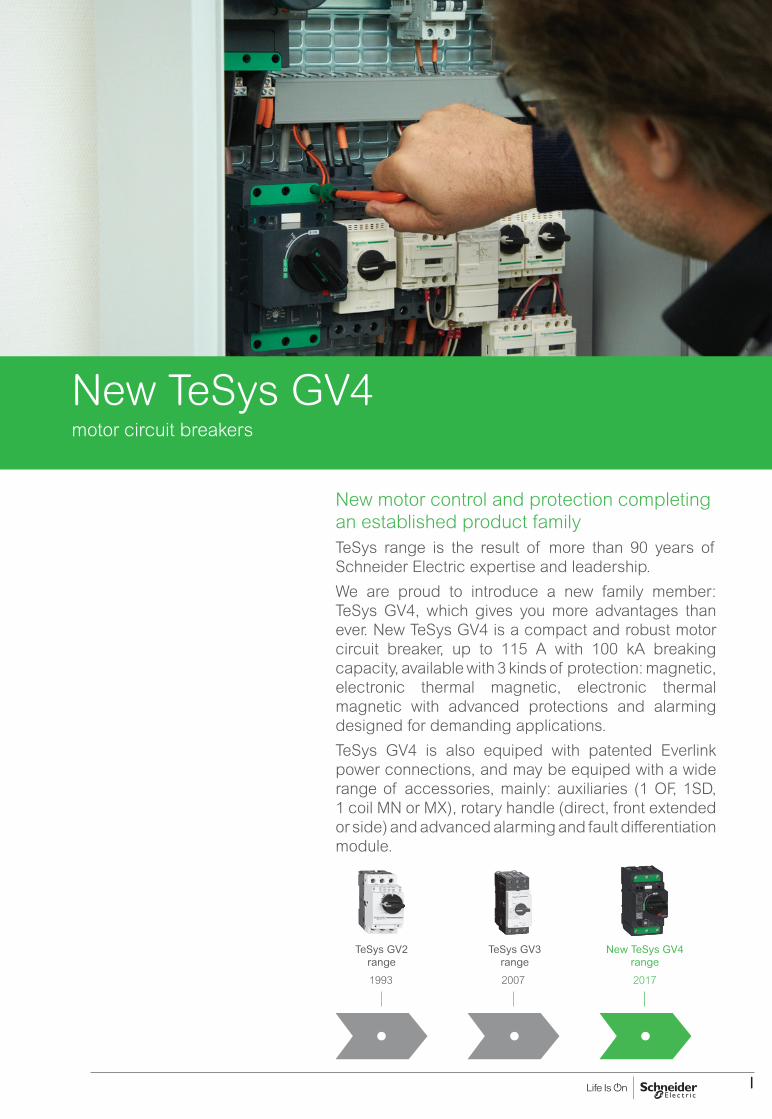
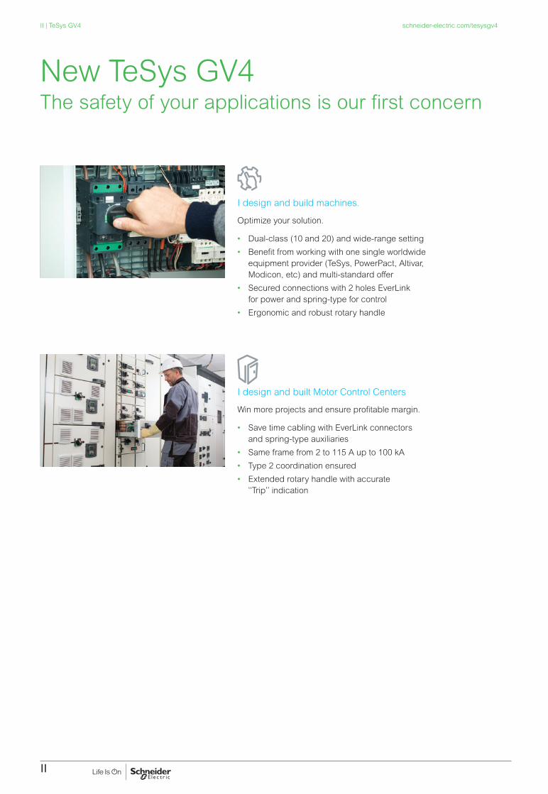
New TeSys GV4
New motor control and protection completing an established product familyTeSys range is the result of more than 90 years of Schneider Electric expertise and leadership.
We are proud to introduce a new family member: TeSys GV4, which gives you more advantages than ever. New TeSys GV4 is a compact and robust motor circuit breaker, up to 115 A with 100 kA breaking capacity, available with 3 kinds of protection: magnetic, electronic thermal magnetic, electronic thermal magnetic with advanced protections and alarming designed for demanding applications.
TeSys GV4 is also equiped with patented Everlink power connections, and may be equiped with a wide range of accessories, mainly: auxiliaries (1 OF, 1SD, 1 coil MN or MX), rotary handle (direct, front extended or side) and advanced alarming and fault differentiation module.
1993
TeSys GV2 range
2007
TeSys GV3 range
2017
New TeSys GV4 range
II
schneider-electric.com/tesysgv4II | TeSys GV4
I design and build machines.
Optimize your solution.
• Dual-class (10 and 20) and wide-range setting
• Benefit from working with one single worldwide equipment provider (TeSys, PowerPact, Altivar, Modicon, etc) and multi-standard offer
• Secured connections with 2 holes EverLink for power and spring-type for control
• Ergonomic and robust rotary handle
I design and built Motor Control Centers
Win more projects and ensure profitable margin.
• Save time cabling with EverLink connectors and spring-type auxiliaries
• Same frame from 2 to 115 A up to 100 kA
• Type 2 coordination ensured
• Extended rotary handle with accurate ‘‘Trip’’ indication
The safety of your applications is our first concern New TeSys GV4

1
Technical Data for Designers page 55
Control and Protection ComponentsTe
Sys
Circuit breakers - TeSys GV2, GV3, GV4 and GV7Type of product Range (400/415 V AC) Pages
PresentationTeSys GV
page 1
Magnetic and thermal magnetic circuit breakersTeSys GV2L, GV2LE,GV2P, GV2ME
0.06 or 15 kW page 9
Thermal magnetic circuit breakers - delayed tripping - For high current peak motors or 3-phase transformersTeSys GV2RT
Add-on blocks, accessories for GV2
0.09 or 11 kW
page 15
Magnetic and Thermal magnetic circuit breakersTeSys GV3L, GV3P
Add-on blocks, accessories
11 to 45 kW
page 21
Magnetic and Thermal magnetic circuit breakersTeSys GV4L, GV4LE, GV4P, GV4PE, GV4PEM
Add-on blocks, accessories
0.25 to 55 kW
page 27
Thermal magnetic circuit breakersTeSys GV7R
Add-on blocks, accessories
55 to 110 kW
page 43
Equipement Circuit breakers - GB
Thermal magnetic circuit breakersTeSys GB
page 51
Circuit breakersTeSys GV2, GV3, GV4 and GV7

2

1
TeSys protection componentsMotor circuit breakers GV2, GV3, GV4 and GV7
Presentation - TeSys GV
Circuit breakers for motor protection and controlTeSys GV motor circuit breakers provide compact, reliable and efficient solutions for:
b isolation, b protection against short circuits and overloads, b On-Off manual control of motors from 0.06 to 110 kW.
They are conforming to, depending of the versions, IEC/EN 60947-1, IEC/EN 60947-2, IEC/EN 60947-4-1 and UL 60497-4-1, CSA 22.2 n° 60497-4-1.
TeSys GV protection technologiesTeSys GV are carried with 3 variants:
b Magnetic detection: GV2LE, GV2L, GV3L, GV4L, GV4LE for protection against short-circuit.
b Thermal-magnetic: GV2ME, GV2P, GV3P, GV4P, GVAPE, GV7R for protection against short-circuits, overload, phase loss and phase unbalance.
b Advanced: GV4PEM combines GV4P protections and motor jam, long start, ground fault protections.With a magnetic circuit breaker, a thermal relay is frequently associated in order to have a short circuit protection and an overload protection.
GV2: 45 mm width, for motors up to 15 kW The most commonly used circuit breaker. with a choice of about 100 auxiliaries and accessories. GV2 and TeSys D or K contactors can be easily assembled as a single block with one accessory. The high GV2 electrical endurance (up to 100 000 manoeuvres) makes it very suitable for direct manual motor control, especially GV2ME (thermal-magnetic c.b., Ith up to 32 A).
Enclosure mounting is well adapted to GV2L and GV2P, with their possible extended rotary handle and visible trip indication.
GV3: 55 mm width, for motors up to 45 kWHigh performance breakers, high breaking capacity (Ics 100 kA /400 V for ratings up to 32 A, 50 kA up to 80 A). Wide choice of auxiliaries / accessories, possible extended rotary handle. Visible tri indication.Patended Everlink connectors provide everlasting connection (no re-tightening required).
Direct monoblock starter assembly with TeSys D contactors. No accessory required.
GV4: 81 mm width, for motors up to 55 kWState-of-the-art technology, GV4 is compact and robust. Electronic core of GV4P gives a great detection accuracy, with alarming and advanced protections for GV4PEM.Magnetic, electronic thermal-magnetic, or electronic thermal magnetic with advanced protections versions.Ratings up to 115 A with breaking capacity Ics of 25 kA/400 V (B series), 50 kA/400 V (N series) or 100 kA/400 V (S series).
GV7: 105 mm width, for motors up to 110 kWGV7 magnetic + electronic detection provide high quality protection to high demanding appliances and power motors. Wide choice of auxiliaries/accessories for advanced applications.
GV2LE
DF5
2614
4.ep
s
GV2P
DF5
2613
7.ep
s
GV2ME
DF5
2613
4.ep
s
GV4pEppp
PB11
4913
.eps
GV4pppp
PB11
4914
.eps
GV7RE
DF5
2613
8.ep
s
GV3P
DF5
2613
9.ep
s
PB11
6862
.eps
GV3P80

2
GV range overviewMolded case circuit breakers for motor protection and control
GV2Protection against Range
(kW / 415 V AC)
Control Terminals Dimensions without toggle (W x H x D)Short-circuits Overload Jam, ground fault,
long start...(Multifunction - see page 4)
GV2L p 0.09 to 15 Rotary handle Screw clamp 44.5 x 89 x 66
GV2LE p 0.06 to 15 Toggle Screw clamp 44.5 x 89 x 66
GV2P p p 0.06 to 15 Rotary handle Screw clamp 44.5 x 89 x 97
GV2ME p p 0.06 to 11 Push button Screw clamp, lug or spring
44.5 x 89 c 67.2 (1)
GV3GV3L p 11 to 45 Rotary handle Lug, EverLink
(BTR screw)55 x 132 x 136 (with toggle)
GV3P p p 5.5 to 45
GV4GV4L p 0.25 to 55 Rotary handle Lug, EverLink
(BTR screw)81 x 154 x 105
GV4LE p Toggle
GV4P p p Rotary handle
GV4PE p p Toggle
GV4PEM p p p Toggle
GV7GV7R p p 55 to 110 Toggle Lug, screw
clamp105 x 161 x 111 (2)
(with toggle)
(1) 44.5 x 101 x 82 mm for GV2MEpp3.(2) 105 x 161 x 126 mm for GV7Rp220.
Presentation - TeSys GV
TeSys protection componentsMotor circuit breakers GV2, GV3, GV4 and GV7
GV2L
DF5
2614
5.ep
s
GV2LE
DF5
2614
4.ep
s
GV2P
DF5
2613
7.ep
s
GV2ME
DF5
2613
4.ep
s
GV3L
DF5
2614
6.ep
s
GV3P
DF5
2613
9.ep
s
GV4L
PB11
4914
_L14
.eps
GV4P
PB11
4914
_L14
.eps
GV7RE
DF5
2613
8.ep
s
GV4PEM
PB11
4917
_14.
eps

3
Presentation - TeSys GV
TeSys protection componentsMotor circuit breakers GV2, GV3, GV4 and GV7
Basic functionsShort circuit protection (magnetic/thermal magnetic circuit breakers)It provides a protection of the installation against short-circuit by an instantaneous trip of the circuit breaker. The tripping is obtained by means of a magnetic element incorporated in the motor circuit breaker or by an electronic detection (GV4P and GV7).The magnetic tripping threshold is not adjustable, except on GV4L, and is a fixed ratio of the maximum setting current In.
Overload protection (thermal magnetic circuit breakers)It provides a protection of the motor against overload. A 5% current increase over In will rise temperature of the motor by 10°, and so will divide its life expectancy by 2.This protection is obtained by means of a thermal element incorporated in the motor circuit breaker, or by sensors for electronic products (GV4P and GV7).An automatic compensation for ambient temperature variations is also provided. The rated operational current of the motor is displayed by turning a graduated knob.
Motor ON/OFF controlThe circuit breaker provides a local manual control of the motor when used on its own (without contactor). The operation is possible by push buttons, toggle, or a single rotary handle.
Contacts position indicationBecause they are suitable for isolation, the circuit breakers, in the open position, provide an adequate isolation distance and indicate the accurate position of the moving contacts by the position of the operators.
Additional functionsThey are provided by additional modules.
Under voltage protectionTrips the circuit breaker in case of under voltage. The user is therefore protected against sudden starting of the machine when normal voltage is restored. Circuit breaker reset and/or start button “I” has to be pressed to restart the motor.
Remote off-powerCircuit breaker can be remotely tripped with the addition of a shunt trip.
Off-power lockingThe operators on both open-mounted and enclosed motor circuit breakers can be locked in the off position “O” by up to 3 padlocks.
2/T1
4/T2
6/T3
1/L1
3/L2
5/L3
DF5
1074
4.ep
s
Thermal protection circuit breaker (with rotary control)
2/T1
4/T2
6/T3
1/L1
3/L2
5/L3
DF5
6906
8.ep
s
Thermal magnetic protection circuit breaker(with rotary control)
Motor circuit breakers versus fuse protection ?Circuit breakers are a common solution for protecting motor against short circuits and overloads. As a comparison, a fuse based solution can only provide a partial protection depending on the choice of the fuse type and rating. The thermal magnetic circuit breaker is adjustable and can be fine-tuned to the practical motor load .The fuse based solution offers a very fast protection.
Fault signalling
9798 06
05
DF5
3747
6.ep
s
Voltage trip
D1
D2
DF5
3746
9.ep
s

4
Presentation - TeSys GV
TeSys protection componentsMotor circuit breakers GV2, GV3, GV4 and GV7
Advanced protections embedded on GVAPEM (multifunction)In addition to basic protections, GV4PEM embed protections against :
b Long start (high inertia, resistive torque machines) b Jam (overtorque, machine failure) b Ground fault (reduced isolation) b Unbalanced (phase currents are not equal) b Phase loss (1 or 2 phases missing)
Fully configurable-advanced protections: b wireless with an application on Android smartphone through NFC (near field
communication).
OFF
OF
SD
TeSys
MN250V
4 68
10
12
2
1
20
10CLASS
Ir(A)RE
AD
Y
ALA
RM>XXA
>95%
1514
li=1725A
Ir Isd Ii
t
i
L1
L2
L3
L1
L2
L3
GV4P EM115S
Uimp 8kV
Ui 800V
In:115A
Ue(V)Icu(kA) Ics(kA)
220/240
380/415
440500525690/690
12010070301810
1201007030182.5
50/60Hz
IEC/EN 60947-2 Cat A
40°C
With Everlink LAD96595
mm² (Rigid)
1 x 1,5.....70 Cu
1 x 1,5.....95 Cu
Power tightening torque
mm²
N.m
y10u16
59
1 x 1,5.....70 Cu
1 x 1,5.....95 Cu
EverLink
Patented technology
DB4
2477
3.ep
s
b with Ecoreach software on a computer connected to the test socket through a configuration and maintenance module
20
10
CLASS
Ir(A)
102100
115
80
75
6570
86 93REA
DY
ALAR
M
>95% T°
PPYY
WW
D
Ir Isd Ii
t
i
li=1955A
L1
L2
L3
DB4
2476
6.ep
s
Remote indications:GV4PEM circuit breaker may be equipped with an SDx alarming / fault differentiation module to prevent to trip or to identify the type of fault after a trip (see page 38).
T
T95%TAMUNB
GF JAMLS
SDX
12
SDX
SDTA
M
N
T
T95%TAMUNB
GF JAMLS
1214
15
64
12
8
OFF
10OFF
OF
SD
TeSys
MN250V
4 68
10
12
2
1
20
10CLASS
Ir(A)RE
AD
Y
ALA
RM>XXA
>95%
1514
li=1725A
Ir Isd Ii
t
i
L1
L2
L3
L1
L2
L3
GV4P EM115S
Uimp 8kV
Ui 800V
In:115A
Ue(V)Icu(kA) Ics(kA)
220/240
380/415
440500525690/690
12010070301810
1201007030182.5
50/60Hz
IEC/EN 60947-2 Cat A
40°C
With Everlink LAD96595
mm² (Rigid)
1 x 1,5.....70 Cu
1 x 1,5.....95 Cu
Power tightening torque
mm²
N.m
y10u16
59
1 x 1,5.....70 Cu
1 x 1,5.....95 Cu
EverLink
Patented technology
mm² (Flexible)
DB4
2493
1.ep
s
PB11
4917
.eps

5
Presentation - TeSys GV
TeSys protection componentsMotor circuit breakers GV2, GV3, GV4 and GV7
No overheating connections - EverLink creep-compensated terminals for GV3 and GV4
The EverLink patented technology for terminals dramatically reduces the risk of loose bare cables due to copper creeping. Vibration withstand is improved and periodic re-tightening is no longer needed.
The clamp connectors which don’t need re-tightening.
Creeping phenomena
Copper conductors are subject to creep with the time, reducing the contact pressure in conventional clamps
During the tightening a force is applied on the conductors and on a spring
Maintaining of cables assured by pressure of spring and crimping of conductor on the contact plate
The spring compensates for cable conductor creep. Tightening force is assured.
EverLink technology for TeSys GV3 and GV4TeSys GV3 and GV4 features a cable connection method with patented creep-compensating technology built directly into the terminal — EverLink:• With EverLink connectors, save space and time during panel assembly.• Bare cable connections are as safe as compression lug ones.
DF5
2613
9.ep
s
EverLink terminals, with BTR screws
DF5
2613
9.ep
sPB
1149
14_2
4.ep
s

6
Presentation - TeSys GV
TeSys protection componentsMotor circuit breakers GV2, GV3, GV4 and GV7
Auxiliary functions provided by add-on blocks
GV2 GV3
GV4 GV7
Auxiliary contacts add-on blocks For control, alarms, automatic actions: b Instantaneous indication of the position of the circuit breaker contacts b Trip indication, b Alarming
Trip units For remote tripping of circuit breaker: b Shunt trip / MX, trips the circuit breaker when powered b Undervoltage release / MN, trips the circuit breaker when voltage is loss
Open/Closepoles status GVAE
Undervoltage releaseGVAUShunt tripGVAS
Open/Closepoles status GVAE
Undervoltage releaseGVAUShunt tripGVAS
Short circuit signallingGVAM11
Short circuit signallingGVAM11
Open/Closepoles statusGV7AE11GV7AB11
Thermal fault alarming / trip signalization moduleGV7AD
MN250V
~/=
SDX
SDx Auxiliary contacts for GV4PEM(alarming and fault differentiation)GV4ADM1111
Trip statusGV4AE11
Open/Closepoles statusGV4AE11
Undervoltage releaseGV4AUShunt tripGV4AS
OFF
OF
SD
TeSys
MN250V
4 68
10
12
2
1
20
10CLASS
Ir(A)RE
AD
Y
ALA
RM>XXA
>95%
1514
li=1725A
Ir Isd Ii
t
i
L1
L2
L3
L1
L2
L3
GV4P EM115S
Uimp 8kV
Ui 800V
In:115A
Ue(V)Icu(kA) Ics(kA)
220/240
380/415
440500525690/690
12010070301810
1201007030182.5
50/60Hz
IEC/EN 60947-2 Cat A
40°C
With Everlink LAD96595
mm² (Rigid)
1 x 1,5.....70 Cu
1 x 1,5.....95 Cu
Power tightening torque
mm²
N.m
y10u16
59
1 x 1,5.....70 Cu
1 x 1,5.....95 Cumm² (Flexible)
EverLink
Patented technology
Undervoltage releaseGV4AUShunt tripGV4AS
DB4
2476
7.ep
s

7
Presentation - TeSys GV
TeSys protection componentsMotor circuit breakers GV2, GV3, GV4 and GV7
Compact power circuits wiring with of GV2 + TeSys D contactors (1)
Busbars and combination blocksPower busbars and combinations blocks provide a compact solution for assembling a group of motor starters. Theysave wiring time and provide a clear finish aspect.These solutions are available for GV2 circuit breakers + TeSys D contactors
DB4
2598
1.ep
s
Quick control circuits wiring of GV2, GV3 + TeSys D contactors (1)
TeSys SoLink RJ45 connection modulesThe LAD5Cpp connection modules ensure compatibility of GV2, GV3 circuit breaker + Tesys D contactor assemblies with the RJ45 connection system. Require screw clamp terminals. Benefits are reduced wiring time, reliable connection.
DB4
2598
2.ep
s
DB4
2598
3.ep
s
SoLink for GV2 + TeSys D Direct, Reverse assemblies SoLink for GV3 + TeSys D Direct, Reverse assemblies
(1) Details on these solution in chapter B2 of TeSys catalogue.

8

99
TeSys GV20.06 to 15 kW

10
References - TeSys GV2 0.06 to 15 kW
Motor circuit breakers from 0.09 to 15 kWGV2L: Control by rotary knob, connection by screw clamp terminalsStandard power ratings of 3-phase motors 50/60 Hz in category AC-3
Magnetic protection rating
Tripping current Id ± 20 %
Use in association with thermal overload relay (class 10 A)
Reference
400/415 V 500 V 690 VP Icu Ics (1) P Icu Ics (1) P Icu Ics (1)
kW kA kW kA kW kA A A0.09 g g – – – – – – 0.4 5 LRD 03 GV2L030.12 g g – – – 0.37 g g 0.63 8 LRD 04 GV2L040.18 g g – – – – – – 0.63 8 LRD 04 GV2L04– – – – – – 0.55 g g 1 13 LRD 05 GV2L050.25 g g – – – – – – 1 13 LRD 05 GV2L05– – – – – – 0.75 g g 1 13 LRD 06 GV2L050.37 g g 0.37 g g – – – 1 13 LRD 05 GV2L050.55 g g 0.55 g g 1.1 g g 1.6 22.5 LRD 06 GV2L06– – – 0.75 g g – – – 1.6 22.5 LRD 06 GV2L060.75 g g 1.1 g g 1.5 4 100 2.5 33.5 LRD 07 GV2L071.1 – – – – – – – – LRD 08 GV2L081.5 g g 1.5 g g 3 4 100 4 51 LRD 08 GV2L08– – – – – – – – – LRD 08 GV2L082.2 g g 3 g g 4 4 100 6.3 78 LRD 10 GV2L103 g g 4 10 100 5.5 4 100 10 138 LRD 12 GV2L144 – – – – – – – – LRD 14 GV2L14– – – – – – 7.5 4 100 10 138 LRD 14 GV2L14– – – – – – 9 4 100 14 170 LRD 16 GV2L165.5 50 50 7.5 10 75 11 4 100 14 170 LRD 16 GV2L167.5 50 50 9 10 75 15 4 100 18 223 LRD 21 GV2L209 50 50 11 10 75 18.5 4 100 25 327 LRD 22 GV2L2211 50 50 15 10 75 – – – 25 327 LRD 22 GV2L2215 50 50 18.5 10 75 22 4 100 32 416 LRD 32 GV2L32
TeSys protection componentsMagnetic motor circuit breakers GV2L
GV2L10
DF5
2614
5.tif
(1) As % of Icu. Associated current limiter or fuses, where required. See characteristics page.g) > 100 kA.

11
Magnetic motor circuit breakers from 0.06 to 15 kWGV2LE: control by rocker lever, connection by screw clamp terminalsStandard power ratings of 3-phase motors 50/60 Hz in category AC-3
Magnetic protection rating
Tripping current Id ± 20 %
Use in association with thermal overload relay
Reference
400/415 V 500 V 690 VP Icu Ics (1) P Icu Ics (1) P Icu Ics (1)
kW kA kW kA kW kA A A0.06 g g – – – – – – 0.4 5 LR2 K0302 GV2LE03
0.09 g g – – – – – – 0.4 5 LR2 K0304 GV2LE03
0.12 g g – – – 0.37 g g 0.63 8 LR2 K0304 GV2LE04
0.18 g g – – – – – – 0.63 8 LR2 K0305 GV2LE04
– – – – – – 0.55 g g 1 13 LR2 K0305 GV2LE05
0.25 g g – – – – – – 1 13 LR2 K0306 GV2LE05
– – – – – – 0.75 g g 1 13 LR2 K0306 GV2LE05
0.37 g g 0.37 g g – – – 1 13 LR2 K0306 GV2LE05
0.55 g g 0.55 g g 1.1 g g 1.6 22.5 LR2 K0307 GV2LE06
– – – 0.75 g g – – – 1.6 22.5 LR2 K0307 GV2LE06
0.75 g g 1.1 g g 1.5 3 75 2.5 33.5 LR2 K0308 GV2LE07
1.1 g g – – – – – – 2.5 33.5 LR2 K0308 GV2LE07
1.5 g g 1.5 g g 3 3 75 4 51 LR2 K0310 GV2LE08
– – – 2.2 g g – – – 4 51 LR2 K0312 GV2LE08
2.2 g g 3 50 100 4 3 75 6.3 78 LR2 K0312 GV2LE10
3 g g 4 10 100 5.5 3 75 10 138 LR2 K0314 GV2LE14
4 g g 5.5 10 100 – – – 10 138 LR2 K0316 GV2LE14
– – – – – – 7.5 3 75 10 138 LRD 14 GV2LE14
– – – – – – 9 3 75 14 170 LRD 16 GV2LE16
5.5 15 50 7.5 6 75 11 3 75 14 170 LR2 K0321 GV2LE16
7.5 15 50 9 6 75 15 3 75 18 223 LRD 21 GV2LE20
9 15 40 11 4 75 18.5 3 75 25 327 LRD 22 GV2LE22
11 15 40 15 4 75 – – – 25 327 LRD 22 GV2LE22
15 10 50 18.5 4 75 22 3 75 32 416 LRD 32 GV2LE32
(1) As % of Icu.g) > 100 kA.
TeSys protection componentsMagnetic motor circuit breakers GV2LE
GV2LE10
DF5
2614
4.tif
References - TeSys GV2 0.06 to 15 kW

12
Motor circuit breakers from 0.06 to 15 kW / 400 V, with screw clamp terminalsGV2ME with pushbutton controlStandard power ratings of 3-phase motors 50/60 Hz in category AC-3
Setting range of thermal trips (2)
Magnetic tripping current Id ± 20 %
Reference
400/415 V 500 V 690 VP Icu Ics (1) P Icu Ics (1) P Icu Ics (1)
kW kA % kW kA % kW kA % A A– – – – – –
– – – 0.1…0.16 1.5 GV2ME01
0.06 g g – – –
– – – 0.16…0.25 2.4 GV2ME02
0.09 g g – – –
– – – 0.25…0.40 5 GV2ME03
0.12 0.18
gg
g g
– –
– –
– –
0.37 –
g –
g –
0.40…0.63 8 GV2ME04
0.25 g g – – –
0.55 g g 0.63…1 13 GV2ME05
0.37 0.55 –
g g –
g g –
0.37 0.55 0.75
g g g
g g g
– 0.75 1.1
– g g
– g g
1…16 22.5 GV2ME06
0.75 g g 1.1 g g
1.5 3 75 1.6…2.5 33.5 GV2ME07
1.1 1.5
g g
g g
1.5 2.2
g g
g g
2.2 3
3 3
75 75
2.5…4 51 GV2ME08
2.2 g g 3 50 100
4 3 75 4…6.3 78 GV2ME10
3 4
g g
g g
4 5.5
10 10
100 100
5.5 7.5
3 3
75 75
6…10 138 GV2ME14
5.5 –
15 –
50 –
7.5 –
6 –
75 –
9 11
3 3
75 75
9…14 170 GV2ME16
7.5 15 50 9 6 75
15 3 75 13…18 223 GV2ME20
9 15 40 11 4 75
18.5 3 75 17…23 327 GV2ME21
11 15 40 15 4 75
– – – 20…25 327 GV2ME22 (3)
15 10 50 18.5 4 75 22 3 75 24…32 416 GV2ME32
Motor circuit breakers from 0.06 to 15 kW / 400 V, with lugsTo order thermal magnetic circuit breakers with connection by lugs, add the digit 6 to the end of reference selected above. Example: GV2ME08 becomes GV2ME086.Thermal magnetic circuit breakers GV2 ME with built-in auxiliary contact block
With instantaneous auxiliary contact block (composition, see page 14):
b GV AE1, add suffix AE1TQ to the motor circuit breaker reference selected above. Example: GV2ME01AE1TQ.b GV AE11, add suffix AE11TQ to the motor circuit breaker reference selected above. Example: GV2ME01AE11TQ.b GV AN11, add suffix AN11TQ to the motor circuit breaker reference selected above. Example: GV2ME01AN11TQ.
These circuit breakers with built-in contact block are sold in lots of 20 units in a single pack.
(1) As % of Icu.(2) The thermal trip setting must be within the range marked on the graduated knob.(3) Maximum rating which can be mounted in enclosures GV2MC or MP, please consult your Regional Sales Office. g > 100 kA.
GV2ME10
DF5
2613
4.tif
TeSys protection componentsThermal-magnetic motor circuit breakers GV2ME
References - TeSys GV2 0.06 to 15 kW

13
TeSys protection components Thermal-magnetic motor circuit breakers GV2ME
Motor circuit breakers from 0.06 to 11 kW, with spring terminal connectionsGV2ME (1) with pushbutton controlStandard power ratings of 3-phase motors 50/60 Hz in category AC-3
Setting range of thermal trips (3)
Magnetic tripping current Id ± 20 %
Reference
400/415 V 500 VP Icu Ics (2) P Icu Ics (2)
kW kA % kW kA % A A– – – – – – 0.1…0.16 1.5 GV2ME013
0.06 g g – – – 0.16…0.25 2.4 GV2ME023
0.09 g g – – – 0.25…0.40 5 GV2ME033
0.120.18
gg
gg
– – – 0.40…0.63 8 GV2ME043
0.250.37
gg
gg
0.37 g g 0.63…1 13 GV2ME053
0.370.55
gg
gg
0.370.550.75
ggg
ggg
1…1.6 22.5 GV2ME063
0.75 g g 1.1 g g 1.6…2.5 33.5 GV2ME073
1.11.5
gg
gg
1.52.2
gg
gg
2.5…4 51 GV2ME083
2.2 g g 3 50 100 4…6.3 78 GV2ME103
34
gg
gg
45.5
1010
100100
6…10 138 GV2ME143
5.5 15 50 7.5 6 75 9…14 170 GV2ME163
7.5 15 50 9 6 75 13…18 223 GV2ME203
911
1515
4040
11 4 75 17…23 327 GV2ME213
11 15 40 15 4 75 20…25 327 GV2ME223
Contact blocksDescription Mounting Maximum
numberType of contacts
Sold in lots of
Unit reference
Instantaneous auxiliary contacts
Front 1 N/O + N/C 10 GVAE113N/O + N/O 10 GVAE203
LH side 2 N/O + N/C 1 GVAN113N/O + N/O 1 GVAN203
AccessoryDescription Application Sold in
lots ofUnit reference
Cable end reducer For connection of conductors from 1 to 1.5 mm2 20 LA9D99
(1) For connection of conductors from 1 to 1.5 mm2, the use of an LA9 D99 cable end reducer is recommended.(2) Maximum rating which can be mounted in enclosures GV2MC or MP, please consult your Regional Sales Office(3) The thermal trip setting must be within the range marked on the graduated knob.g > 100 kA.
GV2MEpp3
DF5
2613
5.tif
LA9 D99
DF5
3389
8.ep
s
References - TeSys GV2 0.06 to 15 kW

14
Motor circuit breakers from 0.06 to 15 kW / 400 V Standard power ratings of 3-phase motors 50/60 Hz in category AC-3
Setting range of thermal trips (2)
Magnetic tripping current Id ± 20 %
Reference
400/415 V 500 V 690 VP Icu Ics (1) P Icu Ics (1) P Icu Ics (1)
kW kA % kW kA % kW kA % A AGV2 P: control by rotary knobScrew clamp terminals
– – – – – – – – – 0.1…0.16 1.5 GV2P010.06 g g – – – – – – 0.16…0.25 2.4 GV2P020.09 g g – – – – – – 0.25…0.40 5 GV2P030.12 0.18
g g
g g
– –
– –
– –
0.37 –
g –
g –
0.40…0.63 8 GV2P04
0.25 g g – – – 0.55 g g 0.63…1 13 GV2P050.37 0.55
g g
g g
0.37 0.55
g g
g g
– 0.75
– g
– g
1…1.6 22.5 GV2P06
0.75 g g 1.1 g g 1.5 8 100 1.6…2.5 33.5 GV2P071.1 g g 1.5 g g 2.2 8 100 2.5…4 51 GV2P082.2 g g 3 g g 4 6 100 4…6.3 78 GV2P103 g g 5 50 100 5.5 6 100 6…10 138 GV2P145.5 –
g –
g –
7.5 –
42 –
75 –
9 11
6 6
100 100
9…14 170 GV2P16
7.5 50 50 9 10 75 15 4 100 13…18 223 GV2P209 50 50 11 10 75 18.5 4 100 17…23 327 GV2P2111 50 50 15 10 75 – – – 20…25 327 GV2P2215 50 50 18.5 10 75 22 4 100 24…32 416 GV2P32
How to use the table : select your load operating voltage, then select its standard power value (below, in the same column). The appropriate circuit breaker is in the extreme right column, in the corresponding row.Exemple; GV2P04 can protect 0.12 and 0.18 kW under 400/415 V, and 0.18 kW under 440 V, and 0,37 kW under 500 V. No 500 V standard power value can fit GV2P04.
Motor circuit breakers up to 50 hp / 600 V, UL 60947-4-1 type EGV2 (3)
To obtain a GV2 P motor circuit breaker, UL 60947-4-1 type E, use the following with the circuit breaker:b a “Large Spacing” adapter GV2GH7.(1) As % of Icu.(2) The thermal trip setting must be within the range marked on the graduated knob.(3) Accessory: see page 16.g > 100 kA.
TeSys protection componentsThermal-magnetic motor circuit breakers GV2P
GV2P10
DF5
2613
7.tif
References - TeSys GV2 0.06 to 15 kW

15
TeSys protection components Thermal-magnetic circuit breakers GV2RT
GV2RT
PB11
1883
.eps
References - TeSys GV2 0.09 to 5 kW
For primaries of 3-phase transformersControl by rocker leverStandard power ratings Setting
range of thermal trips (2)
Magnetic tripping current Id ± 20 %
Reference
230/240 V 400/415 V 440 V 500 V 690 VkW kW kW kW kW A A
– – – – – 0.25…0.40 8 GV2RT03
– – – – – 0.40…0.63 13 GV2RT04
– – 0.63 0.63 1 0.63…1 22 GV2RT05
0.4 0.63 1 1 – 1…1.6 33 GV2RT06
0.63 1 – 1.6 1.62
1.6…2.5 51 GV2RT07
1 1.62
1.62
22.5
2.5 2.5…4 78 GV2RT08
1.62
2.5 2.54
4 456.3
4…6.3 138 GV2RT10
2.5 45
5 56.3
– 6…10 200 GV2RT14
4 6.3 6.3 – 1012.5
9…14 280 GV2RT16
56.3
10 10 1012.5
10 13…18 400 GV2RT20
Accessory (3)
Description ReferencePadlockable external operator (IP 54) black handle, blue legend plate
GV2AP03
(2) The thermal trip setting must be within the range marked on the graduated knob.(3) Other accessories such as mounting, cabling and marking accessories are identical to those used for GV2 ME motor
circuit breakers, see page 17.
For motors with high current peak on startingControl by rocker leverStandard power ratings of 3-phase motors 50/60 Hz in category AC-3
Setting range of thermal trips(1)
Magnetic tripping current Id ± 20 %
Reference
220/ 230 V
400/ 415 V
440 V 500 V 690 V
kW kW kW kW kW A A0.06 0.09 0.09
0.12– – 0.25…0.40 8 GV2RT03
– 0.120.18
0.18 – 0.37 0.40…0.63 13 GV2RT04
0.090.12
0.250.37
0.250.37
0.37 0.55 0.63…1 22 GV2RT05
0.180.25
0.370.55
0.370.55
0.370.550.75
0.751.1
1…1.6 33 GV2RT06
0.37 0.75 0.751.1
1.1 1.5 1.6…2.5 51 GV2RT07
0.550.75
1.11.5
1.5 1.52.2
2.23
2.5…4 78 GV2RT08
1.1 2.2 2.23
3 4 4…6.3 138 GV2RT10
1.52.2
34
4 45.5
5.57.5
6…10 200 GV2RT14
2.23
5.5 5.57.5
7.5 911
9…14 280 GV2RT16
4 7.5 7.59
9 15 13…18 400 GV2RT20
5.5 911
11 11 18.5 17…23 400 GV2RT21
(1) The thermal trip setting must be within the range marked on the graduated knob.

16
GV2 AK00GV1 L3
GV AD
GV AM11
GV AM11
GV AN
GV AN
GV2 P
GV2 ME
GV AX
GV AU
GV AS
GV AE1
GV AE1
GV AE11, GV AE20
GV2 L
GV2 LEGV2 RT
DB4
2528
9.ep
s
17
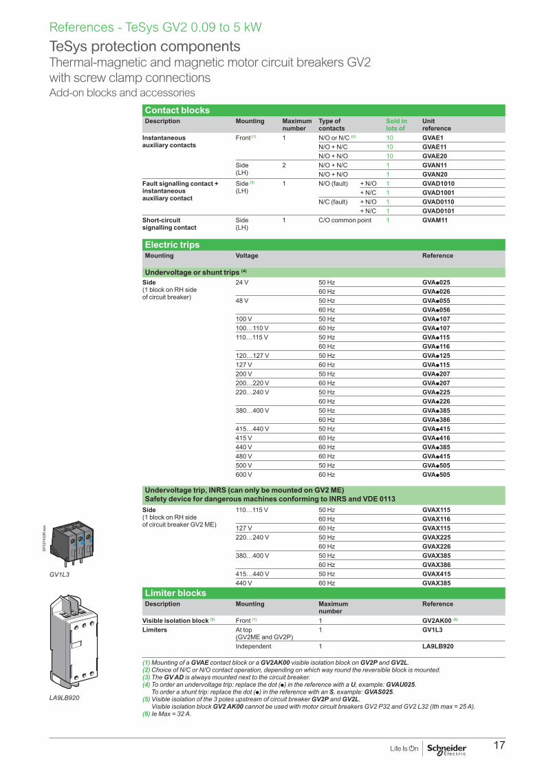
Contact blocksDescription Mounting Maximum
numberType of contacts
Sold in lots of
Unit reference
Instantaneous auxiliary contacts
Front (1) 1 N/O or N/C (2) 10 GVAE1N/O + N/C 10 GVAE11N/O + N/O 10 GVAE20
Side (LH)
2 N/O + N/C 1 GVAN11N/O + N/O 1 GVAN20
Fault signalling contact + instantaneous auxiliary contact
Side (3)
(LH)1 N/O (fault) + N/O 1 GVAD1010
+ N/C 1 GVAD1001N/C (fault) + N/O 1 GVAD0110
+ N/C 1 GVAD0101Short-circuit signalling contact
Side (LH)
1 C/O common point 1 GVAM11
Electric tripsMounting Voltage Reference
Undervoltage or shunt trips (4)
Side (1 block on RH side of circuit breaker)
24 V 50 Hz GVAp02560 Hz GVAp026
48 V 50 Hz GVAp05560 Hz GVAp056
100 V 50 Hz GVAp107100…110 V 60 Hz GVAp107110…115 V 50 Hz GVAp115
60 Hz GVAp116120…127 V 50 Hz GVAp125127 V 60 Hz GVAp115200 V 50 Hz GVAp207200…220 V 60 Hz GVAp207220…240 V 50 Hz GVAp225
60 Hz GVAp226380…400 V 50 Hz GVAp385
60 Hz GVAp386415…440 V 50 Hz GVAp415415 V 60 Hz GVAp416440 V 60 Hz GVAp385480 V 60 Hz GVAp415500 V 50 Hz GVAp505600 V 60 Hz GVAp505
Undervoltage trip, INRS (can only be mounted on GV2 ME) Safety device for dangerous machines conforming to INRS and VDE 0113
Side (1 block on RH side of circuit breaker GV2 ME)
110…115 V 50 Hz GVAX11560 Hz GVAX116
127 V 60 Hz GVAX115220…240 V 50 Hz GVAX225
60 Hz GVAX226380…400 V 50 Hz GVAX385
60 Hz GVAX386415…440 V 50 Hz GVAX415440 V 60 Hz GVAX385
Limiter blocksDescription Mounting Maximum
numberReference
Visible isolation block (5) Front (1) 1 GV2AK00 (6)
Limiters At top (GV2ME and GV2P)
1 GV1L3
Independent 1 LA9LB920
(1) Mounting of a GVAE contact block or a GV2AK00 visible isolation block on GV2P and GV2L.(2) Choice of N/C or N/O contact operation, depending on which way round the reversible block is mounted.(3) The GV AD is always mounted next to the circuit breaker.(4) To order an undervoltage trip: replace the dot (p) in the reference with a U, example: GVAU025.
To order a shunt trip: replace the dot (p) in the reference with an S, example: GVAS025.(5) Visible isolation of the 3 poles upstream of circuit breaker GV2P and GV2L.
Visible isolation block GV2 AK00 cannot be used with motor circuit breakers GV2 P32 and GV2 L32 (Ith max = 25 A).(6) Ie Max = 32 A.
TeSys protection componentsThermal-magnetic and magnetic motor circuit breakers GV2 with screw clamp connectionsAdd-on blocks and accessories
LA9LB920
DF5
3743
2R.e
ps
GV1L3
References - TeSys GV2 0.09 to 5 kW

18
DB1
2662
9.ep
s

19
References - TeSys GV2 0.09 to 5 kW
AccessoriesDescription Application Sold in
lots of Unit reference
Adapter plates For mounting a GV2ME or GV2LE by screw fixing
10 GV2AF02
For mounting a GV2ME and contactor LC1D09…D38 with front faces aligned
1 LAD311
Height compensation plate 7.5 mm 10 GV1F03Combination blocks Between GV2 and contactor LC1K or LP1K 10 GV2AF01
Between GV2 and contactor LC1D09…D38 10 GV2AF3Between GV2 mounted on LAD311 and contactor LC1D09…D38
10 GV2AF4
Motor starter adapter plate With 3-pole connection for mounting a GV2 and a contactor LC1D09…D25
1 GK2AF01
Description Application Pitch Referencemm
Sets of 3-pole Ie = 63 A busbars
2 tap-offs 45 GV2G24554 GV2G25472 GV2G272
3 tap-offs 45 GV2G34554 GV2G354
4 tap-offs 45 GV2G44554 GV2G45472 GV2G472
5 tap-offs 54 GV2G554
Description Ie Application Sold in lots of
Unit reference
AProtective end cover - For unused busbar outlets 5 GV1G10Terminal block for supply to one or more GV2 G busbar sets
63 Connection from the top 1 GV1G0963 Can be fitted with current limiter GV1 L3
(GV2ME and GV2P)1 GV2G05
Cover for terminal block - For mounting in modular panels 10 LA9E07Flexible 3-pole connection for connecting a GV2 to a contactor LC1-D09…D25
25 Centre distance between mounting rails: 100…120 mm
10 GV1G02
Set of connections upstream/downstream
16 For connecting GV2 ME to a printed circuit board 10 GV2GA01
“Large Spacing” adapter UL 60947-4-1 type E
- For GV2 PppH7 (except 32 A) 1 GV2GH7
Clip-in marker holders (supplied with each circuit breaker)
- For GV2P, GV2L, GV2LE and GV2RT (8 x 22 mm)
100 LA9D92
TeSys protection componentsThermal-magnetic and magnetic motor circuit breakers GV2 with screw clamp connectionsAccessories
DB4
1794
2.ep
s
GV1 G09

20
1DB1
2663
1.ep
s
5
3
2
4
DB1
2663
0.ep
s
6
DB1
2663
2.ep
s
7
PB10
6297
_45.e
ps
Extended Rotary HandleAllows a circuit breaker or a starter-controller installed in back of an enclosure to be operated from the front of the enclosure.A rotary handle can be black or red/yellow, IP54 or IP65. It includes a function for locking the circuit breaker or the starter in the O (Off) or I (On) position (depending of the type of rotary handle) by means of up to 3 padlocks with a shank diameter of 4 to 8 mm. The extended shaft must be adjusted to use in different size enclosures. The IP54 rotary handle is fixed with a nut (Ø22) to make easier the assembling. The new Laser Square tool brings the accuracy to align the circuit breaker and the rotary handle.
Padlockable external operators for GV2P and GV2LDescription
1 Kit handle + mounting system2 Universal handle3 Shaft4 Bracket5 Shaft support plate for deep enclosure6 Retrofit accessory7 Laser Square accessory
Kit handle + mounting systemDescription Item Reference
For GV2P/L Black handle, front plate, with trip status, IP 54 1 GV2APN01Red handle, front plate, with trip status, IP 54 1 GV2APN02Black handle, front plate, without trip status, IP 65 1 GV2APN03Red handle, front plate, without trip status, IP 65 1 GV2APN04
For GV2LE Padlocking in “On” and “Off” position Black handle, blue front plate, IP 54
- GV2AP03
Universal handleFor GV2P/L Black handle, with trip status, IP54 2 GVAPB54
Red handle, with trip status, IP54Red handle, without trip status, IP65
22
GVAPR54GVAPR65
Black handle, without trip status, IP 65 1 GVAPB65Shaft
For GV2P/L L = 315 mm 3 GVAPA1Bracket
For GV2P/L 4 GVAPH02Shaft support plate for deep enclosure
For GV2P/L Depth u 250 mm 5 GVAPK11Retrofit accessory
For GV2P/L 6 GVAPP1Laser Square accessory
For GV2P/L 7 GVAPL01Sticker Sold in lots of
Warning label For French 10 - GVAPSFRFor English 10 - GVAPSENFor German 10 - GVAPSDEFor Spanish 10 - GVAPSESFor Chinese 10 - GVAPSCNFor Portuguese 10 - GVAPSPTFor Russian 10 - GVAPSRUFor Italian 10 - GVAPSIT
Padlocking deviceDescription Reference
For all GV2 device
For use with up to 4 padlocks, Ø6 mm shank max. (padlocks not included)
GV2V03
TeSys protection componentsThermal-magnetic and magnetic motor circuit breakers GV2 with screw clamp connections
References - TeSys GV2 0.09 to 5 kW

21
TeSys GV311 to 45 kW
22
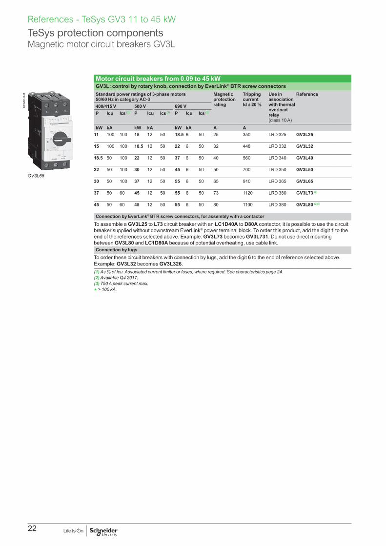
Motor circuit breakers from 0.09 to 45 kWGV3L: control by rotary knob, connection by EverLink® BTR screw connectorsStandard power ratings of 3-phase motors 50/60 Hz in category AC-3
Magnetic protection rating
Tripping current Id ± 20 %
Use in association with thermal overload relay (class 10 A)
Reference
400/415 V 500 V 690 VP Icu Ics (1) P Icu Ics (1) P Icu Ics (1)
kW kA kW kA kW kA A A11 100 100 15 12 50 18.5 6 50 25 350 LRD 325 GV3L25
15 100 100 18.5 12 50 22 6 50 32 448 LRD 332 GV3L32
18.5 50 100 22 12 50 37 6 50 40 560 LRD 340 GV3L40
22 50 100 30 12 50 45 6 50 50 700 LRD 350 GV3L50
30 50 100 37 12 50 55 6 50 65 910 LRD 365 GV3L65
37 50 60 45 12 50 55 6 50 73 1120 LRD 380 GV3L73 (2)
45 50 60 45 12 50 55 6 50 80 1100 LRD 380 GV3L80 (2)(3)
Connection by EverLink® BTR screw connectors, for assembly with a contactorTo assemble a GV3L25 to L73 circuit breaker with an LC1D40A to D80A contactor, it is possible to use the circuit breaker supplied without downstream EverLink® power terminal block. To order this product, add the digit 1 to the end of the references selected above. Example: GV3L73 becomes GV3L731. Do not use direct mounting between GV3L80 and LC1D80A because of potential overheating, use cable link.Connection by lugs
To order these circuit breakers with connection by lugs, add the digit 6 to the end of reference selected above. Example: GV3L32 becomes GV3L326. (1) As % of Icu. Associated current limiter or fuses, where required. See characteristics page 24.(2) Available Q4 2017.(3) 750 A peak current max.g > 100 kA.
TeSys protection componentsMagnetic motor circuit breakers GV3L
References - TeSys GV3 11 to 45 kW
GV3L65
DF5
2614
6.tif

23
Motor circuit breakers from 0.06 to 45 kW / 400 V Standard power ratings of 3-phase motors 50/60 Hz in category AC-3
Setting range of thermal trips (2)
Magnetic tripping current Id ± 20 %
Reference
400/415 V 500 V 690 VP Icu Ics (1) P Icu Ics (1) P Icu Ics (1)
kW kA % kW kA % kW kA % A AGV3P: control by rotary knobConnection by EverLink® BTR screw connectors (3)
5.5 100 100 7.5 12 50 11 6 50 9…13 182 GV3P137.5 100 100 9 12 50 15 6 50 12…18 252 GV3P18 11 100 100 15 12 50 18.5 6 50 17…25 350 GV3P2515 100 100 18.5 12 50 22 6 50 23…32 448 GV3P3218.5 50 100 22 12 50 37 6 50 30…40 560 GV3P4022 50 100 30 12 50 45 6 50 37…50 700 GV3P5030 50 100 45 12 50 55 6 50 48…65 910 GV3P6537 50 60 45 12 50 55 6 50 62...73 1120 GV3P73 (4)
45 50 60 45 12 50 55 6 50 70...80 1120 GV3P80 (4)(5)
Connection by EverLink® BTR screw connectors, for assembly with a contactorTo assemble a GV3P13 to P73 circuit breaker with an LC1D40A to D73A contactor, it is possible to use the circuit breaker supplied without downstream EverLink® power terminal block. To order this product, add the digit 1 to the end of the references selected above. Example: GV3P73 becomes GV3P731. Do not use direct mounting between GV3P80 and LC1D80A because of potential overheating, use cable link.Connection by lugs
To order thermal magnetic circuit breakers with connection by lugs, add the digit 6 to the end of reference selected above. Example: GV3P18 becomes GV3P186.Motor circuit breakers up to 50 hp / 600 V, UL 60947-4-1 type EGV3 (6)
To obtain a motor-circuit breaker GV3P, UL 60947-4-1 type E, use the following with the circuit breaker:b a "Large Spacing" cover GV3G66,b a short-circuit signalling contact GVAM11.GV3 with connection by lugs (6)
To obtain a motor-circuit breaker GV3P, UL 60947-4-1 type E, with connection by lugs, add the digit 6 to the end of reference selected above and use the following with the circuit breaker:b two IP 20 covers LAD96570,b a short-circuit signalling contact GVAM11.(1) As % of Icu.(2) The thermal trip setting must be within the range marked on the graduated knob.(3) BTR screws: hexagon socket head. Require use of an insulated Allen key, in compliance with local wiring regulations.(4) Available Q4 2017.(5) 750 A peak current max.(6) Accessories: see page 25.g > 100 kA.
References - TeSys GV3 11 to 45 kW
TeSys protection componentsThermal-magnetic motor circuit breakers GV3P
GV3P651
DF5
2614
0.tif
GV3P80
PB11
6862
.tif

24
GV AM11
GV AM11
GV AE1
GV AE1
GV AE11, GV AE20,
GV3 L
GV3 P
GV3 G364
GV AE113, GV AE203, GV AED 1013, GV AED 0113
GV AED 101, GV AED 011
GV2 V03
GV3 G264
GV3 APN02
DB1
2663
5.ep
s

25
Contact blocksDescription Mounting Maximum
numberType of contacts
Sold in lots of
Unit reference
Instantaneous auxiliary contacts
Front 1 N/O or N/C (1) 10 GVAE1N/O + N/C 10 GVAE11 (2)
N/O + N/O 10 GVAE20 (2)
Side (LH)
2 N/O + N/C 1 GVAN11 (2)
N/O + N/O 1 GVAN20 (2)
Fault signalling contact + instantaneous auxiliary contact
Front 1 N/O (fault) + N/O 1 GVAED101 (2)
N/O (fault) + N/C 1 GVAED011 (2)
Side (3)
(LH)1 N/O (fault) + N/O 1 GVAD1010
+ N/C 1 GVAD1001N/C (fault) + N/O 1 GVAD0110
+ N/C 1 GVAD0101Short-circuit signalling contact Side (LH) 1 C/O common point 1 GVAM11
Electric trips - undervotlage or shunt (4)
Mounting Voltage Reference
Side (1 block on RH side of circuit breaker)
24 V 50 Hz GVAp02560 Hz GVAp026
48 V 50 Hz GVAp05560 Hz GVAp056
100 50 Hz GVAp107100…110 V 60 Hz GVAp107110…115 V 50 Hz GVAp115
60 Hz GVAp116120…127 V 50 Hz GVAp125127 V 60 Hz GVAp115200 V 50 Hz GVAp207200…220 V 60 Hz GVAp207220…240 V 50 Hz GVAp225
60 Hz GVAp226380…400 V 50 Hz GVAp385
60 Hz GVAp386415…440 V 50 Hz GVAp415415 V 60 Hz GVAp416440 V 60 Hz GVAp385480 V 60 Hz GVAp415500 V 50 Hz GVAp505600 V 60 Hz GVAp505
AccessoriesDescription Reference
Set of 3-pole busbarsIe = 115 APitch: 64 mm
2 tap-off GV3Ppp and GV3Lpp GV3G2643 tap-off GV3Ppp and GV3Lpp GV3G364
Cover "Large Spacing" UL 60947-4-1 type E(Only one cover required on supply side)
GV3Ppp GV3G66
(1) Choice of N/C or N/O contact operation, depending on which way round the reversible block is mounted.(2) Contact blocks available in version with spring terminal connections. Add a figure 3 at the end of the references selected above.
Example: GVAED101 becomes GVAED1013.(3) The GVADpp is always mounted next to the circuit breaker.(4) To order an undervoltage trip: replace the dot (p) in the reference with a U, example: GVAU025.
To order a shunt trip: replace the dot (p) in the reference with an S, example: GVAS025.
TeSys protection componentsThermal-magnetic motor circuit breakers GV3P and GV3LAdd-on blocks and accessories
GV3G66
DF5
3742
4.ep
s
References - TeSys GV3 11 to 45 kW
Limited torque throwaway bits
Torque limiting breakaway bitsDescription Sold in
lots ofReference
5 N.m Yellow 6 LV4269929 N.m Green 6 LV426990
26
References - TeSys GV3 11 to 45 kW
1
DB1
2663
7.ep
s
5
3 2
4
DB1
2663
6.ep
s
6
DB1
2663
2.ep
s
7
PB10
6297
_45.e
ps
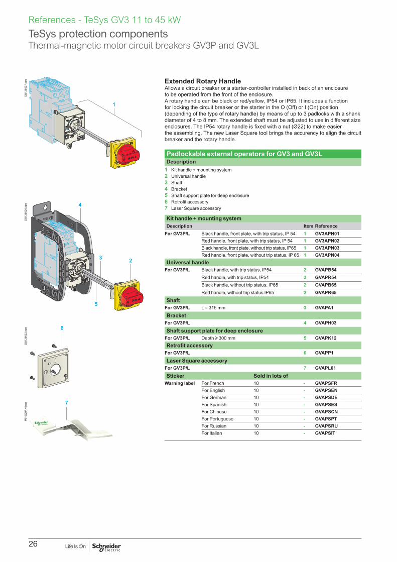
Extended Rotary HandleAllows a circuit breaker or a starter-controller installed in back of an enclosure to be operated from the front of the enclosure.A rotary handle can be black or red/yellow, IP54 or IP65. It includes a function for locking the circuit breaker or the starter in the O (Off) or I (On) position (depending of the type of rotary handle) by means of up to 3 padlocks with a shank diameter of 4 to 8 mm. The extended shaft must be adjusted to use in different size enclosures. The IP54 rotary handle is fixed with a nut (Ø22) to make easier the assembling. The new Laser Square tool brings the accurency to align the circuit breaker and the rotary handle.
Padlockable external operators for GV3 and GV3LDescription
1 Kit handle + mounting system2 Universal handle3 Shaft4 Bracket5 Shaft support plate for deep enclosure6 Retrofit accessory7 Laser Square accessory
Kit handle + mounting systemDescription Item Reference
For GV3P/L Black handle, front plate, with trip status, IP 54 1 GV3APN01Red handle, front plate, with trip status, IP 54 1 GV3APN02Black handle, front plate, without trip status, IP65 1 GV3APN03Red handle, front plate, without trip status, IP 65 1 GV3APN04
Universal handleFor GV3P/L Black handle, with trip status, IP54 2 GVAPB54
Red handle, with trip status, IP54 2 GVAPR54Black handle, without trip status, IP65 2 GVAPB65Red handle, without trip status IP65 2 GVAPR65
ShaftFor GV3P/L L = 315 mm 3 GVAPA1Bracket
For GV3P/L 4 GVAPH03Shaft support plate for deep enclosure
For GV3P/L Depth u 300 mm 5 GVAPK12Retrofit accessory
For GV3P/L 6 GVAPP1Laser Square accessory
For GV3P/L 7 GVAPL01Sticker Sold in lots of
Warning label For French 10 - GVAPSFRFor English 10 - GVAPSENFor German 10 - GVAPSDEFor Spanish 10 - GVAPSESFor Chinese 10 - GVAPSCNFor Portuguese 10 - GVAPSPTFor Russian 10 - GVAPSRUFor Italian 10 - GVAPSIT
TeSys protection componentsThermal-magnetic motor circuit breakers GV3P and GV3L

27
TeSys GV40.25 to 55 kW

28
TeSys protection componentsTeSys GV4 overview
References - TeSys GV4 - 0.25 to 55 kW
ProtectionTeSys GV4 motor circuit breaker covers motor protection from 0.25 to 55 kW at 415 V AC (from 0.8 to 115 A) in one frame and is available in 3 breaking capacities: 25, 50 and 100 kA at 415 V AC IEC (15, 35, 65 kA at 480 V UL).
Tesys GV4 is available with 3 types of protection: b Magnetic GV4L: to be used with an overload relay or a drive b Thermal magnetic GV4P: electronic protection with wide range setting, dual class (10 & 20) b Multifunction motor protection GV4PEM: GV4P with adjustable advanced protections and possibility to have
a side module SDx for alarming and fault differentiation.
Power connectionsTeSys GV4 comes in standard with 2-holes EverLink™ power connectors with creep (1) compensation for bare copper cables. This Schneider Electric patended technique makes it possible to achieve accurate and durable tightening torque in order to avoid cable creep.Products may be delivered too with connectors for bars or cables with compression lugs.Whatever, the connectors are field interchangeables and can be removed for the installation of one of both.And to tight at the right torque power connections particularly in the field, torque limiting breakaway bits may be used.
OF
SD
EverLink
Patented technology
DB4
2566
4.ep
s
OF
SD
DB4
2592
6.ep
s
MountingTeSys GV4 can be mounted on a backplate or on a DIN rail (35 or 75 mm).
HandleTeSys GV4 can be ordered with a toggle or a direct rotary handle (except for GV4P Multifunction). It is also possible to equip a toggle one with a direct rotaty handle, or a front extended one, or a side one.
AuxiliariesTeSys GV4 circuit breakers can be equiped with an open/close (OF) contact and a trip indication (SD) contact. These contacts are common point changeover type, with a normaly open (NO) and a normaly closed (NC) contact.TeSys GV4 may be equiped too with an MN (undervoltage release) or MX (shunt trip) coil.
GV4P Multifunction circuit breakers can be equiped with 1 or 2 SDx module(s) in order to have alarming and fault differentiation (SDx - See page 38)
Auxiliaries have spring connections for cables up to 1.5 mm².
OF
SD
Trip
O
I
SDx
DB4
2575
2.ep
s
OF
SD
Trip
O
I
MN/MX
DB4
2497
9.ep
s
OF
SD
Trip
O
I
OF SD
DB4
2497
8.ep
s
(1) Creep: normal crushing phenomenon of condustors, that is accentuated over time.

29
References - TeSys GV4 0.25 to 55 kW
TeSys protection componentsTeSys GV4 overview
LS
GF
T95%TxxsTAM
T JAMUNB
SDx
12
SDx
SDTA
M
ON
LS
GF
T95%TxxsTAM
T JAMUNB
1214
15
64
12
8
OFF
10
OF
SD
TeSys
O
MN250V
L1
L2
L3
GV4P EM115S
Uimp 8kV
Ui 800V
In:115A
Ue(V)Icu(kA) Ics(kA)
220/240
380/415
440500525690/690
12010070301810
1201007030182.5
50/60Hz
IEC/EN 60947-2 Cat A
40°C
With Everlink LAD96595
mm² (Rigid)
1 x 1,5.....70 Cu
1 x 1,5.....95 Cu
Power tightening torque
mm²
N.m
y10u16
59
mm² (Rigid)
1 x 1,5.....70 Cu
1 x 1,5.....95 Cu
4 68
10
12
2
1
20
10CLASS
Ir(A)RE
AD
Y
ALA
RM>XXA
>95%
1514
li=1725A
Ir Isd Ii
t
i
MX250V
~/=
EverLink
Patented technology
Everlink20 mm
GV4G
Everlink
Ø 4...8
On
Off
Reset
Trip
Ø 4...8
Ø 4...8
Tri
p
Res
et
TeSys
GV4PEM115S
LISTED CB
Issue No:186
E10027
GB14048.2
240V480V600Y/347
1006514
50/60Hz
Cat.A
Ø 4...8
Tri
p
Res
et
TeSys
GV4PEM115S
LISTED CB
Issue No:186
E10027
GB14048.2
240V480V600Y/347
1006514
50/60Hz
Cat.A
Ø 4...8
Tri
p
Res
et
Ø 4...8
On
Off
Reset
Trip
TeSys
GV4PEM115S
LISTED CB
Issue No:186
E10027
GB14048.2
240V480V600Y/347
1006514
50/60Hz
Cat.A
Axial ref.
OFF
Ø 4...8
TeSys
GV4PEM115S
LISTED CB
Issue No:186
E10027
GB14048.2
240V480V600Y/347
1006514
50/60Hz
Cat.A
Ø 4...8
DB4
2529
0.ep
s
11
1313
12
14
14
15
1 Long terminal shield LAD965902 Terminal spreaders LV4269403 Interphases barriers LV4269204 Large spacing cover for EverLink connector GV4G665 Crimp lug connector GV4LUG6 EverLink® connector LAD965957 Torque limiting breakaway bits LV42699p8 SDx alarming/fault differentiation module GV4ADM1111 (only with GV4PEM)9 Auxiliary contact block for OF or SD function GV4AE11
10 - MN undervoltage release GV4AUpp - MX shunt trip GV4ASpp
11 Direct mounting black or red on yellow bezel rotary handle GV4ADN01/ GV4ADN0212 Open door shaft operator (for front extended rotary handle) LV42693713 Front extended rotary handle kit with red handle on yellow bezel or black handle GV4APN01/
GV4APN02 /GV4APN0414 Side rotary handle kit with red handle on yellow bezel or black handle LV426935/LV426936.15 Toggle locking device 29370
1
2
3
5
6
7
8
11
9
910
4
30
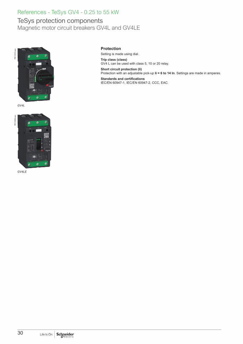
TeSys protection componentsMagnetic motor circuit breakers GV4L and GV4LE
References - TeSys GV4 - 0.25 to 55 kW
GV4L
PB11
4910
.eps
GV4LE
PB11
4909
.eps
ProtectionSetting is made using dial.
Trip class (class)GV4 L can be used with class 5, 10 or 20 relay.
Short circuit protection (Ii)Protection with an adjustable pick-up Ii = 6 to 14 In. Settings are made in amperes.
Standards and certificationsIEC/EN 60947-1, IEC/EN 60947-2, CCC, EAC.

31
Magnetic motor circuit breakers from 0.25 to 55 kWStandard power ratings of 3-phase motors - 50 / 60 Hz In Magnetic
setting range (Ii)
Use in association with overload relay Class 10 or 20
Reference with EverLink terminals
400/415 V 500 V 690 V
P Icu Ics (1) P Icu Ics (1) P Icu Ics (1) with toggle with rotary handle
kW kA % kW kA % kW kA % A A
0.25... 0.75 25 100 0.37… 1.1 10 100 0.55… 1.5 - - 2 12… 28 LRD05 (0.63… 1A) LRD06 (1… 1.6A) LRD07 (1.6… 2.5A)
- -
50 100 25 100 8 25 GV4LE02N GV4L02N
100 100 30 100 10 25 GV4LE02S -
0.55… 1.5 25 100 0.75… 1.5 10 100 1.1… 2.2 - - 3,5 21… 49 LRD07 (1.6… 2.5A) LRD08 (2.5… 4A)
- -
50 100 25 100 8 25 GV4LE03N GV4L03N
100 100 30 100 10 25 GV4LE03S -
1.5… 3 25 100 2.2… 4 10 100 3… 7.5 - - 7 42… 98 LRD08 (2.5… 4A) LRD10 (4…6A)
- -
50 100 25 100 8 25 GV4LE07N GV4L07N
100 100 30 100 10 25 GV4LE07S -
3… 5.5 25 100 3… 7.5 10 100 5.5… 11 - - 12,5 75… 175 LRD12 (5.5… 8A) LRD14 (7… 10A) LRD313 (9…13A)
- -
50 100 25 100 8 25 GV4LE12N GV4L12N
100 100 30 100 10 25 GV4LE12S -
5.5… 11 25 100 7.5… 15 10 100 7.5… 18.5 - - 25 150… 350 LRD318 (12… 18A) LRD325 (17… 25A)
GV4LE25B GV4L25B
50 100 25 100 8 25 GV4LE25N GV4L25N
100 100 30 100 10 25 GV4LE25S -
11… 22 25 100 15… 30 10 100 18.5... 45 - - 50 300… 700 LRD332 (23… 32A) LRD340 (30… 40A) LRD350 (37… 50A)
GV4LE50B GV4L50B
50 100 25 100 8 25 GV4LE50N GV4L50N
100 100 30 100 10 25 GV4LE50S -
18.5… 37 25 100 22… 55 10 100 30… 55 - - 80 480… 1120 LRD365 (48… 65A) LRD3363 (63… 80A)
GV4LE80B GV4L80B
50 100 25 100 8 25 GV4LE80N GV4L80N
100 100 30 100 10 25 GV4LE80S -
30… 55 25 100 30… 75 10 100 45… 90 - - 115 690… 1610 LR9D5567 (60… 100A) LR9F5367 (60… 100A) LR9D5369 (90… 150A) LR9F5369 (90…150A)
GV4LE115B GV4L115B
50 100 25 100 8 25 GV4LE115N GV4L115N
100 100 30 100 10 25 GV4LE115S -
Connection by lugsTo order circuit breakers with connection by lugs, add the digit 6 to the end of reference selected above. Example: GV4LE02N becomes GV4LE02N6.(1) As % of Icu.
TeSys protection componentsMagnetic motor circuit breakers GV4L and GV4LE
References - TeSys GV4 - 0.25 to 55 kW
32
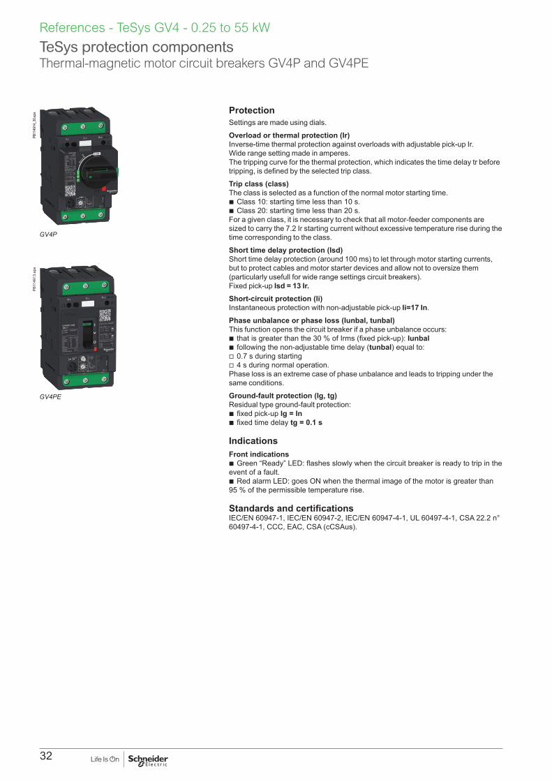
TeSys protection components Thermal-magnetic motor circuit breakers GV4P and GV4PE
ProtectionSettings are made using dials.
Overload or thermal protection (Ir)Inverse-time thermal protection against overloads with adjustable pick-up Ir. Wide range setting made in amperes. The tripping curve for the thermal protection, which indicates the time delay tr before tripping, is defined by the selected trip class.
Trip class (class)The class is selected as a function of the normal motor starting time.
b Class 10: starting time less than 10 s. b Class 20: starting time less than 20 s.
For a given class, it is necessary to check that all motor-feeder components are sized to carry the 7.2 Ir starting current without excessive temperature rise during the time corresponding to the class.
Short time delay protection (Isd)Short time delay protection (around 100 ms) to let through motor starting currents, but to protect cables and motor starter devices and allow not to oversize them (particularly usefull for wide range settings circuit breakers). Fixed pick-up Isd = 13 Ir.Short-circuit protection (li)Instantaneous protection with non-adjustable pick-up Ii=17 In.
Phase unbalance or phase loss (Iunbal, tunbal)This function opens the circuit breaker if a phase unbalance occurs:
b that is greater than the 30 % of Irms (fixed pick-up): Iunbal b following the non-adjustable time delay (tunbal) equal to: v 0.7 s during starting v 4 s during normal operation.
Phase loss is an extreme case of phase unbalance and leads to tripping under the same conditions.
Ground-fault protection (Ig, tg)Residual type ground-fault protection:
b fixed pick-up Ig = In b fixed time delay tg = 0.1 s
IndicationsFront indications
b Green “Ready” LED: flashes slowly when the circuit breaker is ready to trip in the event of a fault.
b Red alarm LED: goes ON when the thermal image of the motor is greater than 95 % of the permissible temperature rise.
Standards and certificationsIEC/EN 60947-1, IEC/EN 60947-2, IEC/EN 60947-4-1, UL 60497-4-1, CSA 22.2 n° 60497-4-1, CCC, EAC, CSA (cCSAus).
References - TeSys GV4 - 0.25 to 55 kW
GV4PE
PB11
4913
.eps
GV4P
PB11
4914
_30.
eps

33
TeSys protection components Thermal-magnetic motor circuit breakers GV4P and GV4PE
References - TeSys GV4 - 0.25 to 55 kW
Thermal magnetic motor circuit breakers from 0.25 to 55 kWStandard power ratings of 3-phase motors - 50 / 60 Hz in category AC-3 Thermal setting
range (Ir)Reference with EverLink terminals
400/415 V 500 V 690 V
P Icu Ics (1) P Icu Ics (1) P Icu Ics (1) with toggle with rotary handle
kW kA % kW kA % kW kA % A
0.25... 0.75 25 100 0.37… 1.1 10 100 0.55… 1.5 - - 0.8… 2 - -
50 100 25 100 8 25 GV4PE02N GV4P02N
100 100 30 100 10 25 GV4PE02S -
0.55… 1.5 25 100 0.75… 1.5 10 100 1.1… 2.2 - - 1.4… 3.5 - -
50 100 25 100 8 25 GV4PE03N GV4P03N
100 100 30 100 10 25 GV4PE03S -
1.5… 3 25 100 2.2… 4 10 100 3… 7.5 - - 2.9… 7 - -
50 100 25 100 8 25 GV4PE07N GV4P07N
100 100 30 100 10 25 GV4PE07S -
3… 5.5 25 100 3… 7.5 10 100 5.5… 11 - - 5… 12.5 - -
50 100 25 100 8 25 GV4PE12N GV4P12N
100 100 30 100 10 25 GV4PE12S -
5.5… 11 25 100 7.5… 15 10 100 7.5… 18.5 - - 10… 25 GV4PE25B GV4P25B
50 100 25 100 8 25 GV4PE25N GV4P25N
100 100 30 100 10 25 GV4PE25S -
11… 22 25 100 15… 30 10 100 18.5... 45 - - 20… 50 GV4PE50B GV4P50B
50 100 25 100 8 25 GV4PE50N GV4P50N
100 100 30 100 10 25 GV4PE50S -
22… 37 25 100 30… 55 10 100 37… 55 - - 40… 80 GV4PE80B GV4P80B
50 100 25 100 8 25 GV4PE80N GV4P80N
100 100 30 100 10 25 GV4PE80S -
37… 55 25 100 45… 75 10 100 75… 90 - - 65… 115 GV4PE115B GV4P115B
50 100 25 100 8 25 GV4PE115N GV4P115N
100 100 30 100 10 25 GV4PE115S -
Connection by lugsTo order circuit breakers with connection by lugs, add the digit 6 to the end of reference selected above. Example: GV4PE02N becomes GV4PE02N6.(1) As % of Icu.

34
TeSys protection components Thermal-magnetic motor circuit breakers GV4PEM
Basic protectionSettings are made using dials.
Overloads or thermal protection (Ir)Inverse-time thermal protection against overloads with adjustable pick-up Ir. Wide range setting made in amperes. The tripping curve for the thermal protection, which indicates the time delay tr before tripping, is defined by the selected trip class.
Trip class (class)The class is selected as a function of the normal motor starting time.
b Class 10: starting time less than 10 s. b Class 20: starting time less than 20 s.
For a given class, it is necessary to check that all motor-feeder components are sized to carry the 7.2 Ir starting current without excessive temperature rise during the time corresponding to the class.
Short-circuit protection (li)Instantaneous protection with non-adjustable pick-up Ii=17 In.
Advanced protectionSettings are made with an Android smartphone with dedicated application and using wireless NFC (Near Field Communication), or a computer with Ecoreach software and the configuration/maintenance tool kit (“Maintenance case” TRV00910)
Short time delay protection (Isd)Short time delay protection (around 100 ms) to let through motor starting currents, but to protect cables and motor starter devices and allow not to oversize them (particularly usefull for wide range settings circuit breakers). Adjustable pick-up Isd = 5...13 Ir (13 by default).
Phase unbalance or phase loss (Iunbal, tunbal)This function opens the circuit breaker if a phase unbalance occurs:
b that is greater than the 10…40 % of Irms (30% by default): Iunbal b following a time delay (tunbal) equal to: v 0.7 s during starting (non adjustable) v 1…10 s during normal operation (4 s by default).
Phase loss is an extreme case of phase unbalance and leads to tripping under the same conditions.
Ground-fault protection (Ig, tg)Residual type ground-fault protection, with OFF position:
b adjustable pick-up Ig: v 0.7…1 In for products with nominal current from 2 to 50 A v 0.4…1 In for products with nominal current from 80 to 115 A b adjustable time delay tg 0.1...0.4 s.
Jam (Ijam, tjam)This function detects locking of the motor shaft caused by the load, with OFF position (OFF by default). During motor starting the function is disabled.During normal operation, it causes tripping:
b above the Ijam pick-up that can be fine-adjusted from 1.5 to 8 Ir b in conjunction with the tjam time delay that can be adjusted from 1 to 30 s.
Long start (Ilong, tlong)This protection supplements thermal protection (class). It is used to better adjust protection to the starting parameters, with OFF position (OFF by default).It detects abnormal motor starting i.e. when the starting current remains too high or too low with respect to a pick-up value and a time delay.It causes tripping:
b in relation with a llong pick-up that can be fine-adjusted from 1.5 to 8 Ir b in conjunction with the tlong time delay that can be adjusted from 1 to 200 s.
IndicationsFront indications
b Green "Ready" LED: flashes slowly when the circuit breaker is ready to trip in the event of a fault.
b Red alarm LED: goes ON when the thermal image of the motor is greater than 95 % of the permissible temperature rise
Remote indications via SDx moduleSee description on page 38.
Standards and certificationsIEC/EN 60947-1, IEC/EN 60947-2, IEC/EN 60947-4-1, UL 60497-4-1, CSA 22.2 n° 60497-4-1, CCC, EAC, CSA (cCSAus).
References - TeSys GV4 - 0.25 to 55 kW
GV4PEM
PB11
4917
.eps

35
TeSys protection components Thermal-magnetic motor circuit breakers GV4PEM
References - TeSys GV4 - 0.25 to 55 kW
Thermal magnetic motor circuit breakers from 0.25 to 55 kWStandard power ratings of 3-phase motors - 50 / 60 Hz in category AC-3 Thermal setting
range (Ir)"Reference with EverLink terminals"
400/415 V 500 V 690 V
P Icu Ics (1) P Icu Ics (1) P Icu Ics (1) with toggle
kW kA % kW kA % kW kA % A
0.25... 0.75 25 100 0.37… 1.1 10 100 0.55… 1.5 - - 0.8… 2 -
50 100 25 100 8 25 GV4PEM02N
100 100 30 100 10 25 GV4PEM02S
0.55… 1.5 25 100 0.75… 1.5 10 100 1.1… 2.2 - - 1.4… 3.5 -
50 100 25 100 8 25 GV4PEM03N
100 100 30 100 10 25 GV4PEM03S
1.5… 3 25 100 2.2… 4 10 100 3… 7.5 - - 2.9… 7 -
50 100 25 100 8 25 GV4PEM07N
100 100 30 100 10 25 GV4PEM07S
3… 5.5 25 100 3… 7.5 10 100 5.5… 11 - - 5… 12.5 -
50 100 25 100 8 25 GV4PEM12N
100 100 30 100 10 25 GV4PEM12S
5.5… 11 25 100 7.5… 15 10 100 7.5… 18.5 - - 10… 25 GV4PEM25B
50 100 25 100 8 25 GV4PEM25N
100 100 30 100 10 25 GV4PEM25S
11… 22 25 100 15… 30 10 100 18.5... 45 - - 20… 50 GV4PEM50B
50 100 25 100 8 25 GV4PEM50N
100 100 30 100 10 25 GV4PEM50S
22… 37 25 100 30… 55 10 100 37… 55 - - 40… 80 GV4PEM80B
50 100 25 100 8 25 GV4PEM80N
100 100 30 100 10 25 GV4PEM80S
37… 55 25 100 45… 75 10 100 75… 90 - - 65… 115 GV4PEM115B
50 100 25 100 8 25 GV4PEM115N
100 100 30 100 10 25 GV4PEM115S
Connection by lugsTo order circuit breakers with connection by lugs, add the digit 6 to the end of reference selected above. Example: GV4PE02N becomes GV4PE02N6.(1) As % of Icu.

36
TeSys protection components Auxiliary contact bloc
References - TeSys GV4 - 0.25 to 55 kW
Auxiliary contact blocksAuxiliary contacts give an indication of the circuit breaker status.They can be used for remote visual signaling, alarming, electrical locking, relay activation, etc...An auxiliary contact block provides one changeover contact with common point for OF or SD function, depending on the breaker cavity where it is inserted.
Auxiliary contact - Open/Close OF functionIndicates Open/Closed position of the circuit breaker contacts.
Auxiliary contact - Trip alarm SD function b Indicates that the circuit breaker has tripped due to: v Electrical fault (overload, short circuit, ...) v shunt trip v undervoltage release v "push-to-trip" button. b Resets when circuit breaker is reset.
Electrical characteristicCharacteristics
Rated thermal current (A) 5Minimum load 2 mA at 17 V DCUtilization cat. (IEC 60947-5-1) AC12 AC15 DC12 DC13 DC14
Operationalcurrent (A)
24 V AC/DC 5 5 5 2.5 148 V AC/DC 5 5 2.5 1.2 0.2110...127 V AC / 110 V DC 5 4 0.6 0.35 0.05220/240 V AC 5 3 - - -250 V DC - - 0.3 0.05 0.03380/440 V AC 5 2.5 - - -660/690 V AC 5 0.11 - - -
Pilot duty B600 according UL508 and CSA 22.2 n°14.
Installation and connection b Auxiliary contact blocks snap into left (for OF function) and right (for SD function)
cavities behind the front accessory cover of the circuit breaker and their presence is visible on the front face through green flags.
b One model serves for all indication functions depending on where it is fitted in the circuit breaker.
b Each NO and NC spring terminal may be connected by one 0.5...1.5 mm² flexible copper wire and by two for the common point.
b Wires can be exited out of any of the four corners of the breaker under the accessory cover.
Description Maximum number
Mounting Type of contacts
Sold in lots of
Reference
Auxiliary contact block for OF or SD indication
2 (1 OF + 1 SD)
Internal plug-in
NO + NC 1 GV4AE11
PB11
4961
.eps
GV4AE11 auxiliary contact block
OFF
OF
SD
TeSys
MN250V
4 68
10
12
2
1
20
10CLASS
Ir(A)RE
AD
Y
ALA
RM>XXA
>95%
1514
li=1725A
Ir Isd Ii
t
i
L1
L2
L3
L1
L2
L3
GV4P EM115S
Uimp 8kV
Ui 800V
In:115A
Ue(V)Icu(kA) Ics(kA)
220/240
380/415
440500525690/690
12010070301810
1201007030182.5
50/60Hz
IEC/EN 60947-2 Cat A
40°C
With Everlink LAD96595
mm² (Rigid)
1 x 1,5.....70 Cu
1 x 1,5.....95 Cu
Power tightening torque
mm²
N.m
y10u16
59
mm² (Rigid)
1 x 1,5.....70 Cu
1 x 1,5.....95 Cu
EverLink
Patented technology
OF
MN250V
L1
SD
L3
DB4
2491
8.ep
s
Visible presence of auxiliary contact block in OF or SD cavity
20 mm
EverLink
EverLinkPatented technology
DB4
2566
5.ep
s
OF SD
OF
SD
Trip
O
IDB4
2566
6.ep
s
Pluggable auxiliary contact - OF or SD is dependent on cavity. Multiple internal wiring possibilities, even with long terminal shields
DB4
2597
7.ep
s

37
TeSys protection components MX shunt trips, MN voltage releases
MX shunt trip, MN undervoltage releaseMX and MN trip the circuit breaker on a control signal. They are mainly used for remote and emergency-off commands.It is advised to test the system every six months.
MX shunt trip b Trips the circuit breaker when the control voltage rises above 70 % of its rated voltage (Un). b Impulse type u 20 ms or maintained control signals. b Shunt trip 110...130 V AC is suitable for ground-fault protection when combined with a Class I groundfault
sensing element. b Continuous duty rated coil (1).
0.7 Un0
Possible opening Failsafe opening
1.1DB4
2127
1.ep
s
Opening conditions of the MX release.
MN undervoltage release b Trips the circuit breaker when the control voltage drops below 35 % of its rated voltage. b Between 35 % and 70 % of the rated voltage opening is possible but not guaranted. b Above 70 % of the rated voltage, opening does not take place. b Continuous duty rated coil. b Circuit breaker closing is possible only if the voltage exceeds 85 % of the rated voltage. If an undervoltage
condition exists, operation of the closing mechanism of the circuit breaker will not permit the main contacts to touch, even momentarily. This is commonly called "Kiss Free".
0.70.35 Un0
Possible openingFailsafe opening
1.1
DB4
2126
9.ep
s
0.85 Un0
Failsafe closing
1.1DB4
2127
0.ep
s
Opening conditions of the MN release. Closing conditions of the MN release.
Installation, connectionAccessories snap into cavities under the circuit breaker front accessory cover. Spring-type terminals in order to insure a fast and reliable connection to 0.5...1.5 mm² flexible copper wire (one per terminal).
OperationCircuit breaker must be locally reset after trip by shunt trip (MX) or undervoltage release (MN).Tripping by MX or MN has priority over manual closing; in the presence of a standing trip order such an action does not result in main contacts closing, even temporarily.
Description Maximum number
Mounting Voltage Reference
MX Shunt trip 1 Internal,plug-in
24 Va 50/60 Hz, 24 Vc GV4AS02748 Va 50/60 Hz, 48 Vc GV4AS057110-130 Va 50/60 Hz 125 Vc GV4AS137220-240 Va 50 Hz, 208-240 Va 60 Hz, 277 V 60 Hz GV4AS287380-415 Va 50 Hz, 440-480 Va 60 Hz GV4AS487
MN undervoltage release
1 Internal,plug-in
24 Va 50/60 Hz, 24 Vc GV4AU02748 Va 50/60 Hz, 48 Vc GV4AU057110-130 Va 50/60 Hz 125 Vc GV4AU137220-240 Va 50 Hz, 208-240 Va 60 Hz GV4AU247277 Va 60 hZ GV4AU286380-415 Va 50 Hz GV4AU415440-480 Va 60 Hz GV4AU486
(1) Except for MX 24 V AC/DC (in case of continuous activation, may generate some minor perturbation in sensitive environment).
References - TeSys GV4 - 0.25 to 55 kWPB
1149
63.e
ps
GV4AS137 shunt trip
20 mm
EverLink
EverLinkPatented technology
DB4
2566
7.ep
sD
B425
668.
eps
MN or MX plugged into cavity.Multiple internal wiring possibilities, even with long terminal shields
DB4
2491
9.ep
s
OFF
OF
SD
TeSys
MN250V
4 68
10
12
2
1
20
10CLASS
Ir(A)RE
AD
Y
ALA
RM>XXA
>95%
1514
li=1725A
Ir Isd Ii
t
i
L1
L2
L3
L1
L2
L3
GV4P EM115S
Uimp 8kV
Ui 800V
In:115A
Ue(V)Icu(kA) Ics(kA)
220/240
380/415
440500525690/690
12010070301810
1201007030182.5
50/60Hz
IEC/EN 60947-2 Cat A
40°C
With Everlink LAD96595
mm² (Rigid)
1 x 1,5.....70 Cu
1 x 1,5.....95 Cu
Power tightening torque
mm²
N.m
y10u16
59
mm² (Rigid)
1 x 1,5.....70 Cu
1 x 1,5.....95 Cu
EverLink
Patented technology
MN250V
L1
Visible presence of MN undervoltage release in circuit breaker cavity, visible rated voltage through the window.

38
TeSys protection componentsSDx contact module for GV4PEM circuit breaker
SDx contact module for GV4PEM (Multifunction)The SDx provides alarming and fault differentiation for the GV4PEM (Multifunction) circuit breaker.This module has 2 NO/NC outputs dry contacts which can be assigned with one of the 8 following SD status:
b SDT95% overload alarm: thermal image of the motor is greater than 95 % of the permissible temperature rise. b SDTxxs overload alarm: circuit breaker will trip in xx seconds with the same load. xx is adjustable between
10 to 40 seconds (default 20 seconds) on the circuit breaker itself through NFC or a computer with Ecoreach software and an interface module (TRV00911).
b SDTAM overload alarm just before tripping: in the event of a phase unbalance, overload, or on a jam fault, this output is activated to open the contactor and avoid circuit breaker tripping. In that case, contact can be manually or automatically reseted after an adjustable cooling time from 1 to 15 minutes. If after a 400 ms delay the motor is not stopped, the circuit breaker will trip.
b SDT overload trip indication: circuit breaker has tripped due to an overload fault b SDJAM jam trip indication: circuit breaker has tripped due to a jam fault b SDUNB phase unbalance trip indication: circuit breaker has tripped due to an unbalance fault b SDLS long start trip indication: circuit breaker has tripped due to a long start fault b SDGF ground fault trip indication: circuit breaker has tripped due to a ground fault.
Outputs are automatically resetted either when alarm disappears or when the circuit breaker is restarted.
Output characteristics b 2 NO/NC dry contacts b 24...250 V AC/DC b 2 mA...5 A max b AC15 (230 V max - 400 VA) b DC13 (24 V - 50 W)
Power characteristics b 24...240 V AC/DC
Installation, connection, settings and indicationThe SDx module is clipped on the right side of the circuit breaker. Each removable spring terminal can be connected by one 0.5... 1.5 mm² copper wire. Settings and indications are available on the front face.
* *
* I1, I2: PLC digital inputs - used as alarm inputs,as an example.
T
T95%
TAMUNB
GF
JAM
LSTxxs
T
T95%
TAMUNB
GF
JAM
LSTxxs
a/c (+)
a/c (-)
a/c (-)
a/c (+)SDxSDL1 SD12 SD14 SD22 SD24
SDL2 SD11 SD13 SD21 SD23
Alarm FaultI1 I2
DB4
2592
7.ep
s
SDx wiring diagram
> 112 %Thermal level
Motor current
SDT95% (1)
SDTAM (2)
SDT (3)
OF
SD
95 %
In
400ms
Time
Tripping thresholdTr
ippi
ng
Reset
DB4
2592
8.ep
s
GV4PEM curves
SDx modules curves
Aux. contacts curves
(1) SDT95% (= 95% overload)(2) SDTAM (overload tripping pre alarm) here not connected
to any contactor coil(3) SDT (= tripping on thermal fault)
Description Mounting Maximum number
Type of contacts
Unit reference
SDx: alarming / fault differentiation module
Side 2 N/O / N/C GV4ADM1111
References - TeSys GV4 - 0.25 to 55 kW
GV4ADM1111 SDx contact module
LS
GF
T95%TxxsTAM
T JAMUNB
SDx
12
SDx
SDTA
M
ON
LS
GF
T95%TxxsTAM
T JAMUNB
1214
15
64
12
8
OFF
10
DB4
2478
6.ep
s
SDx
1SD
TAM
ON
T
T95%
TAMUNB
GF
JAM
LS
1214
15
64
12
8
OFF
10
Txxs
2SD
xT95%
TTAM
UNB
GF
JAM
LSTxxs
DB4
2529
3.ep
s
1
2
3
6
4
5
1 Green led lighted when the module is powered.
2 Output 1: SD status assignment.
3 Red led lighted when output 1 is activated.
4 Cooling time setting before automatic restart (OFF – 1…15 min).
5 Output 2: SD status assignment.
6 Red led lighted when output 2 is activated.

39
TeSys protection components Rotary handles
References - TeSys GV4 - 0.25 to 55 kW
Direct mounting rotary handlesInstallationThe direct mounting rotary handle has to be mounted by 3 screws on the front accessory cover.OperationThe direct mounting rotary handle maintains:
b suitability for isolation b indication of the three positions OFF (O), ON (I) and tripped (Trip) b access to the "push-to-trip" button b visibility and access to the trip unit.
Device padlockingThe circuit breaker may be locked in the OFF position by using one to three padlocks (not supplied) or in ON position after customer modification of the rotary handle before installation, padlock shackle Ø4-8 mm. Locking in the ON position does not prevent the circuit breaker from tripping if a fault occurs. In this case, the handle remains in the ON position after the circuit breaker trips. Unlocking is required for the handle to go to the tripped then the OFF position.Variations: door locking Door locking built-in functionality can be activated by the customer to prevent opening the door when the circuit breaker is ON or in trip position. For exceptional situations, door locking can be temporarily disabled with a tool by qualified personel to open the door when the circuit breaker is closed. Description Type Degree of protection Reference
Direct mounting rotary handle
Black handle IP40 GV4ADN01Red handle on yellow bezel(VDE standard, for machine control)
IP40 GV4ADN02
Front extended rotary handlesInstallationThe door-mounted (extended) rotary handle is made up of:
b a unit that has to be screwed on the front accessory cover of the circuit breaker b an assembly (handle mechanism and front plate) on the door that is always secured
in the same position, whether the circuit breaker is installed vertically or horizontally b an adjustable extension shaft.
The handle mechanism is fixed with a nut (Ø22 mm) to make assembly easier. The Laser Square tool (GVAPL01) can be used to accurately align the hole on the door with the circuit breaker.Operation when door is closedThe door mounted handle makes it possible to operate a circuit breaker installed in an enclosure from the front. The door mounted operating handle maintains:
b suitability for isolation b indication of the three positions OFF (O), ON (I) and tripped (Trip) b visibility and access to trip unit when the door is open b degree of protection of the handle on the door: IP54 or IP65 as per IEC 529.
Mechanical door locking when device closedA standard feature of the extended rotary handle is a locking function, built into the shaft, that disables door opening when the circuit breaker is in the ON or tripped positions.Door locking can be temporarily disabled with a tool by qualified personnel to open the door without opening the circuit breaker. This operation is not possible if the handle is locked by a padlock.Device and door padlockingPadlocking locks the circuit breaker handle and disables door opening:
b standard situation, in the OFF position, using 1 to 3 padlocks, shackle Ø4-8 mm, padlocks are not supplied
b for the black handle, with a voluntary modification of the door handle (to be done by the customer during installation), in the ON and OFF positions. Locking in the ON position does not prevent the circuit breaker from tripping if a fault occurs. In this case, the handle remains in the ON position after the circuit breaker trips. Unlocking is required for the handle to go to the tripped then the OFF position.
Shaft lengthThe shaft length is the distance between the back of the circuit breaker and the door:
b minimum shaft length is 214 mm b maximum shaft length is 627 mm b shaft length must be adjusted.
Tri
p
Ø 4...8
On
Off
Reset
Trip
GV4APN01 front extended rotary handle kit
DB4
2477
7.ep
sD
B421
644.
eps
GVAPL01 laser tool
Ø 4...8
Tri
p
Res
et4P fram
e
Ø 4...8
DB4
2510
2.ep
s
GV4ADN02 direct mounting rotary handle
OF
SD
1L1
3L2
5L3
EverLink
Patented technology
Trip
4P fram
e
Tri
p
Res
et4P fram
e
Ø 4...8
On
Off
Reset
Trip
Ø 4...8
On
Off
Reset
Trip
DB4
2492
1.ep
s
Front extended rotary handle (door-mounting)
OF
SD
1L1
3L2
5L3
EverLink
Patented technology
Trip Ø 4...8
4P fram
e
Tri
p
Res
et
Ø 4...8
4P fram
e
Ø 4...8 T
rip
Res
et4P fram
e
Ø 4...8
DB4
2492
0.ep
s
Direct mounting rotary handle

40
TeSys protection components Rotary handles
References - TeSys GV4 - 0.25 to 55 kW
Front extended rotary handles (cont.)Operation when door is openedAn open door shaft operator can be used to operate the circuit breaker when door is opened. This accessory complies with UL508 A.The indication of the three positions OFF (O), ON (I) and tripped (Trip) is visible onthe circuit breaker.The circuit breaker itself may be locked in OFF position when the door is opened by 1 padlock / lockout hasp, shackle Ø4-8 mm.
Description Type Degree of protection ReferenceFront extendedrotary handle kit
Black handle IP54 GV4APN01Red handle on yellow bezel
IP54 GV4APN02IP65 GV4APN04
Open door shaft operator LV426937Laser tool GVAPL01GV4 universal handle (spare for front ext. & side rotary handle)
Black handle IP54 LV426997Red handle on yellow bezel
IP54 LV426998IP65 LV426999
Side rotary handles (left or right)InstallationThe side-mounted rotary handle is made up of:
b a unit that has to be screwed on the front accessory cover of the circuit breaker b an assembly (handle and front plate) on the side (left or right) of the enclosure b an adjustable extension shaft
The handle mechanism is fixed with a nut (Ø22 mm) to make assembly easier.OperationThe side mounted rotary handle makes it possible to operate circuit breakers installed in enclosure from the side. The side mounted rotary handle maintains:
b suitability for isolation b indication of the three positions OFF (O), ON (I) and tripped (Trip). Moreover,
the position is visible on the circuit breaker itself b visibility and access to trip unit when the door is open b degree of protection of the handle on the side: IP54 or IP65 as per IEC 529.
Device padlockingThe circuit breaker may be locked in the OFF position, or, for the black rotary handle only, in ON position after voluntary modification of the side handle (to be done by the customer during installation), by using one to three padlocks, padlock shackle Ø4-8 mm ; padlocks are not supplied.Locking in the ON position does not prevent free circuit breaker from tripping if a faultoccurs. In this case, the handle remains in the ON position after the circuitbreaker tripping. Unlocking is required to go to the tripped then the OFF position.Shaft lengthThe shaft length is the distance between the side of the circuit breaker and the side of the enclosure:
b minimum shaft length is 45 mm b maximum shaft length is 480 mm b shaft length must be adjusted.
Description Type Degree of protection ReferenceSide rotary handle kit
Black handle IP54 LV426935Red handle on yellow bezel (VDE standard, for machine control)
IP54 (1) LV426936
GV4 universal handle (spare for front ext. & side rotary handle)
Black handle IP54 LV426997Red handle on yellow bezel IP54 LV426998
IP65 LV426999
(1) IP65 possible with LV426935 kit (Black handle not used) + LV426999 Red handle on yellow bezel universal handle.
LV426937 open door shaft operator
DB4
2493
6.ep
s
Ø 4...8
On
Off
Reset
Trip
Ø 4...8
On
Off
Reset
Trip
Ø 4...8
LV426998, LV426997 universal handles
DB4
2477
9.ep
s
Axial ref.
OFF
Ø 4...8
LV426936 side rotary handle kit
DB4
2477
8.ep
s
OF
SD
1L1
3L2
5L3
EverLink
Patented technology
Trip
Ø 4...8
Axial ref.
OFF
Ø 4...8
Side extended rotary handle (cover mounting)
DB4
2492
3.ep
s
OF
SD
1L1
3L2
5L3
EverLink
Patented technology
Trip
4P fram
e
Tri
p
Res
et4P fram
e
Ø 4...8
On
Off
Reset
Trip
Open door shaft operator mounted on front extended rotary handle assembly
DB4
2510
8.ep
s
Tri
p
Ø 4...8
On
Off
Reset
Trip
GV4APN01 front extended rotary handle kit
DB4
2477
7.ep
sD
B421
644.
eps
GVAPL01 laser tool

41
TeSys protection componentsLocks and sealing accessories
DB4
2301
8.ep
s
LV429375 leads + sealing accessories
References - TeSys GV4 - 0.25 to 55 kW
Handle padlocking devicesPadlocking systems can receive up to three padlocks with diameters of 5-8 mm (4-8 mm for rotary handles); padlocks not supplied. Locking in the OFF position guarantees isolation as per IEC 60947-2.Direct rotary handle padlockingBy padlock – No accessory required.
b Lock in OFF position. b Lock in ON position with simple mechanism modification.
Front Extended /Side rotary handle padlockingBy padlock – No accessory required.
b Lock in OFF position. b Lock in ON position with simple mechanism modification (black handle only).
Door opening prevented.Toggle handle padlockingBy padlock – removable toggle locking device required 29370.
b Lock in OFF position.O
F
SD
EverLink
Patented technology
DB4
2492
6.ep
s
3 padlocks mounted on 29370 toggle locking device
Description ReferenceRemovable toggle locking device for 1 to 3 padlocks 29370
Sealing devicesControl type b Front removal.
b Access to auxiliaries. b Access to settings and test connector.
Toggle
OF
SD
EverLink
Patented technology
SD
DB4
2492
7.ep
s
OF
SD
EverLink
Patented technology
DB4
2492
8.ep
s
Rotary handle
OF
SD
EverLink
Patented technology
Ø 4...8
Tri
p
Res
et
Ø 4...8
SD
DB4
2492
9.ep
s
OF
SD
EverLink
Patented technology
Ø 4...8
4P fram
e
Tri
p
Res
et
Ø 4...8
DB4
2493
0.ep
s
Description ReferenceBag of 6 leads + 6 sealing accessories LV429375
DB4
2494
4.ep
s
29370 removable toggle locking device

42
TeSys protection componentsCabling, test accessories, softwares
References - TeSys GV4 - 0.25 to 55 kW
EverLink power connectionDescription Reference
EverLink connector LAD96595Large spacing cover for EverLink connector GV4G66
Crimp lug/busbar connectionDescription Sold in
lots ofReference
Crimped lug connector + screws 1 GV4LUGTransparent terminal shield for crimped lug connector 1 LAD96590Interphase barriers 6 LV426920Spreader 3-pole To increase the pitch to 35 mm 1 LV426940
Limited torque throwaway bitsDescription Sold in
lots ofReference
Green - 9 N.m 6 LV426990Yellow - 5 N.m 6 LV426992Note: torque limiting breakaway bits may be used, particularly in the field, to tighten at the right torque EverLink™ or compression lug power connections.
Test tool, software, demo for GV4PEMTest tool
Pocket battery LV434206
Maintenance case TRV00910Comprising:
b USB maintenance interface b Power supply b GV4PEM cord b USB cord b RJ45/RJ45 male cord
Spare USB maintenance interface TRV00911
Spare power supply 110-240 V AC TRV00915
Spare GV4PEM cord for USB maintenance interface TRV00917
SoftwareConfiguration and setting software Ecoreach Free download
LAD96595 EverLink connector
EverLink
Patented technology
DB4
2493
5.ep
s
GV4G66 large spacing cover for EverLink connector
Everlink20 mm
GV4G
Everlink
DB4
2529
1.ep
sEverlink20 mm
GV4G
Everlink
GV4LUG crimped lug connector
DB4
2493
4.ep
s
LV426940 spreader 3-pole
DB4
2478
0.ep
s
LV426992 5 N.m yellow throwaway bits
DB4
2593
1.ep
s
LAD96590 transparent terminal shield
DB4
2478
1.ep
s
LV426920 interphase barriers
DB4
2478
2.ep
s
LV426990 9 N.m green throwaway bits
DB4
2593
2.ep
s
DB4
2493
8.ep
s
TRV00910 maintenance case
DB4
2493
9R.e
ps
LV434206 pocket battery
DB4
2494
1.ep
s
TRV00917 spare GV4PEM cord for USB maintenance interface
DB4
2494
0.ep
s
TRV00915 spare power supply 110-240 V AC
DB4
2493
9.ep
s
TRV00911 Spare USB maintenance interface
43
TeSys GV755 to 110 kW

44

45
Thermal-magnetic circuit breakers GV7R with screw clamp terminals up to 110 kWControl by rocker leverStandard power ratings of 3-phase motors 50/60 Hz in category AC-3
Setting range of thermal trips
Reference Weight
400/415 V 500 V 660/690 VP Icu Ics (1) P Icu Ics (1) P Icu Ics (1)
kW kA % kW kA % kW kA % A kg5575
3535
100100
7590
3030
100100
90110
88
100100
90…150 GV7RE150 2.020
5575
7070
100100
7590
5050
100100
90110
1010
100100
90…150 GV7RS150 2.020
90110
3535
100100
110132160
303030
100100100
160200
88
100100
132…220 GV7RE220 2.350
90110
7070
100100
110132160
505050
100100100
160200
1010
100100
132…220 GV7RS220 2.350
(1) As % of lcu.
GV7RS220
DF5
2614
1.tif
TeSys protection components Thermal-magnetic motor circuit breakers GV7R
References - TeSys GV7 55 to 110 kW

46
GV7 RE, RS
GV7 AE11, AB11
GV7 AU, AS
12
34
DF5
2634
4.ep
s
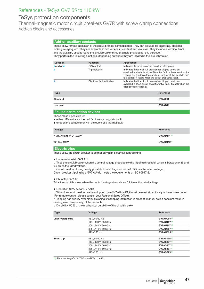
47
References - TeSys GV7 55 to 110 kW
Add-on auxiliary contactsThese allow remote indication of the circuit breaker contact states. They can be used for signalling, electrical locking, relaying, etc. They are available in two versions: standard and low level. They include a terminal block and the auxiliary circuits leave the circuit breaker through a hole provided for this purpose.They perform the following functions, depending on where they are located in the circuit breaker:
Location Function Application1 and/or 4 C/O contact Indicates the position of the circuit breaker poles2 Trip indication Indicates that the circuit breaker has tripped due to an
overload, a short-circuit, a differential fault or the operation of a voltage trip (undervoltage or shunt trip), or of the “push to trip” test button. It resets when the circuit breaker is reset.
3 Electrical fault indication Indicates that the circuit breaker has tripped due to an overload, a short-circuit or a differential fault. It resets when the circuit breaker is reset.
Type Reference
Standard GV7AE11
Low level GV7AB11
Fault discrimination devicesThese make it possible to:b either differentiate a thermal fault from a magnetic fault,b or open the contactor only in the event of a thermal fault.
Voltage Reference
a 24...48 and c 24…72 V GV7AD111 (1)
z 110…240 V GV7AD112 (1)
Electric tripsThese allow the circuit breaker to be tripped via an electrical control signal.
b Undervoltage trip GV7 AUv Trips the circuit breaker when the control voltage drops below the tripping threshold, which is between 0.35 and 0.7 times the rated voltage.v Circuit breaker closing is only possible if the voltage exceeds 0.85 times the rated voltage. Circuit breaker tripping by a GV7 AU trip meets the requirements of IEC 60947-2.
b Shunt trip GV7 ASTrips the circuit breaker when the control voltage rises above 0.7 times the rated voltage.
b Operation (GV7 AU or GV7 AS)v When the circuit breaker has been tripped by a GV7 AU or AS, it must be reset either locally or by remote control. (For remote control, please consult your Regional Sales Office).v Tripping has priority over manual closing: if a tripping instruction is present, manual action does not result in closing, even temporarily, of the contacts.v Durability: 50 % of the mechanical durability of the circuit breaker.
Type Voltage Reference
Undervoltage trip 48 V, 50/60 Hz GV7AU055 (1)
110…130 V, 50/60 Hz GV7AU107 (1)
200…240 V, 50/60 Hz GV7AU207 (1)
380…440 V, 50/60 Hz GV7AU387 (1)
525 V, 50 Hz GV7AU525 (1)
Shunt trip 48 V, 50/60 Hz GV7AS055 (1)
110…130 V, 50/60 Hz GV7AS107 (1)
200…240 V, 50/60 Hz GV7AS207 (1)
380…440 V, 50/60 Hz GV7AS387 (1)
525 V, 50 Hz GV7AS525 (1)
(1) For mounting of a GV7AD or a GV7AU or AS.
TeSys protection componentsThermal-magnetic motor circuit breakers GV7R with screw clamp connectionsAdd-on blocks and accessories

48
ON
OFFO
ON
OFFO
ON
OFFO
OFFO
ON
ON
OFFO
GV7 RE, RS
GV7 AP03
OFFO
ON
GV7 AP04
GV7 AP01, AP02
GV7 V01
GV7 AP05
GV7 RE, RS
GV7 AC01
GV7 AC03 GV7 AC01
GV7 AC04
GV7 AC04
DF5
2634
3.ep
s

49
Cabling accessoriesDescription Application For use on
contactorsSold in lots of
Unit reference
Clip-on connectors for GV7 R
Up to 150 A, 1.5…95 mm2 – 3 GV7AC021
Up to 220 A, 1.5…185 mm2 – 3 GV7AC022
Spreader 3-pole (1)
To increase the pitch to 45 mm – 1 GV7AC03
Terminal shields IP 405 (1)
Supplied with sealing accessory
– 1 GV7AC01
Phase barriers Safety accessories used when fitting of shields is impossible
– 2 GV7AC04
Insulating screens Ensure insulation between the connections and the backplate
– 2 GV7AC05
Kits for combination with contactor (2)
Allowing link between the circuit breaker and the contactor. The cover provides protection against direct finger contact
LC1F115…F185 1 GV7AC06
LC1F225 and F265 1 GV7AC07
LC1D115 and D150 1 GV7AC08
Direct rotary handleReplaces the circuit breaker front cover; secured by screws. It includes a device for locking the circuit breaker in the O (Off) position by means of up to 3 padlocks with a shank diameter of 5 to 8 mm (padlocks not included). A conversion accessory allows the direct rotary handle to be mounted on the enclosure door. In this case, the door cannot be opened if the circuit breaker is in the “ON” position. Circuit breaker closing is inhibited if the enclosure door is open.
Description Type Degree of protection
Reference
Direct rotary handle Black handle, black legend plate IP 40 GV7AP03
Red handle, yellow legend plate IP 40 GV7AP04
Adapter plate (3) Four mounting direct rotary handle on enclosure door
IP 43 GV7AP05
Extended rotary handleAllows a circuit breaker installed in the back of an enclosure to be operated from the front of the enclosure. It comprises:b a unit which screws onto the front cover of the circuit breaker,b an assembly (handle and front plate) to be fitted on the enclosure door,b an extension shaft which must be adjusted (distance between the mounting surface and the door: 185 mm minimum, 600 mm maximum). It includes a device for locking the circuit breaker in the O (Off) position by means of up to 3 padlocks with a shank diameter of 5 to 8 mm (padlocks not included). This prevents the enclosure door from being opened.
Description Type Degree of protection
Reference
Extended rotary handle Black handle, black legend plate IP 55 GV7AP01
Red handle, yellow legend plate IP 55 GV7AP02
Locking deviceAllows circuit breakers not fitted with a rotary handle to be locked in the O (Off) position by means of up to 3 padlocks with a shank diameter of 5 to 8 mm (padlocks not included).
Description Application Reference
Locking device For circuit breaker not fitted with a rotary handle GV7V01
(1) Terminal shields cannot be used together with spreaders.(2) The kit comprises links, a protective shield and a depth adjustable metal bracket for the breaker.(3) This conversion accessory makes it impossible to open the door if the device is closed and prevents the device from being
closed if the door is open.
TeSys protection componentsThermal-magnetic motor circuit breakers GV7R with screw clamp connectionsAccessories
GV7AC07
+
+
DF5
3742
9.ep
s
GV7AC08
+
DF5
3742
8.ep
s
References - TeSys GV7 55 to 110 kW

50
51
TeSys GB20.5 to 20 A (for equipment and control circuits)
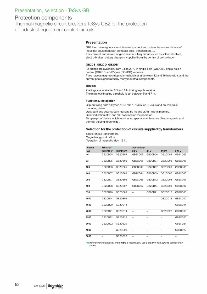
52
PresentationGB2 thermal-magnetic circuit breakers protect and isolate the control circuits of industrial equipment with contactor coils, transformers.…They protect and isolate single-phase auxiliary circuits such as solenoid valves, electro-brakes, battery chargers, supplied from the control circuit voltage. GB2CB, GB2CD, GB2DB12 ratings are available, from 0.5 to 20 A, in single-pole (GB2CB), single-pole + neutral (GB2CD) and 2-pole (GB2DB) versions.They have a magnetic tripping threshold set at between 12 and 16 In to withstand the current peaks generated by many industrial components. GB2 CS2 ratings are available, 0.5 and 1 A, in single-pole version.The magnetic tripping threshold is set between 5 and 7 In. Functions, installationClip-on fixing onto all types of 35 mm 5 rails, on 4 rails and on Telequick mounting plates.Upstream and downstream marking by means of AB1 clip-in markers.Clear indication of “I” and “O” positions on the operator.Tamper-proof device which requires no special maintenance (fixed magnetic and thermal tripping thresholds). Selection for the protection of circuits supplied by transformersSingle-phase transformers.Magnetising peak: 20 In.Operation of magnetic trips: 13 In. Power Primary (1) SecondaryVA 220/240 V 380/415 V 24 V 48 V 110 V 220 V
40 GB2DB05 GB2DB05 GB2CD07 GB2CD06 GB2CD05 GB2CD05
63 GB2DB05 GB2DB05 GB2CD08 GB2CD07 GB2CD06 GB2CD05
100 GB2DB06 GB2DB05 GB2CD10 GB2CD07 GB2CD06 GB2CD05
160 GB2DB07 GB2DB06 GB2CD14 GB2CD09 GB2CD07 GB2CD06
250 GB2DB07 GB2DB06 GB2CD16 GB2CD12 GB2CD08 GB2CD07
400 GB2DB08 GB2DB07 GB2CD22 GB2CD14 GB2CD09 GB2CD07
630 GB2DB10 GB2DB08 – GB2CD21 GB2CD12 GB2CD08
1000 GB2DB14 GB2DB09 – – GB2CD16 GB2CD10
1600 GB2DB20 GB2DB14 – – – GB2CD14
2000 GB2DB21 GB2DB14 – – GB2CD22 GB2CD16
2500 GB2DB22 GB2DB20 – – – GB2CD20
3000 GB2DB22 GB2DB20 – – – GB2CD21
4000 – GB2DB21 – – – GB2CD22
5000 – GB2DB22 – – – –
(1) If the breaking capacity of the GB2 is insufficient, use a GV2RT with 2 poles connected in series.
Protection componentsThermal-magnetic circuit breakers TeSys GB2 for the protection of industrial equipment control circuits
Presentation, selection - TeSys GB

53
References - TeSys GB
Circuit breakers with magnetic tripping threshold: 12 to 16 InSingle-poleConventional rated thermal current Ith (1)
Magnetic tripping current Id ± 20 %
Sold in lots of
Unit reference
A A0.5 6.6 6 GB2CB051 14 6 GB2CB062 26 6 GB2CB073 40 6 GB2CB084 52 6 GB2CB095 66 6 GB2CB106 83 6 GB2CB128 108 6 GB2CB1410 138 6 GB2CB1612 165 6 GB2CB2016 220 6 GB2CB2120 270 6 GB2CB22
Single-pole + neutralConventional rated thermal current Ith (1)
Magnetic tripping current Id ± 20 %
Sold in lots of
Unit reference
A A0.5 6.6 6 GB2CD051 14 6 GB2CD062 26 6 GB2CD073 40 6 GB2CD084 52 6 GB2CD095 66 6 GB2CD106 83 6 GB2CD128 108 6 GB2CD1410 138 6 GB2CD1612 165 6 GB2CD2016 220 6 GB2CD2120 270 6 GB2CD22
2-poleConventional rated thermal current Ith (1)
Magnetic tripping current Id ± 20 %
Sold in lots of
Unit reference
A A0.5 6.6 3 GB2DB051 14 3 GB2DB062 26 3 GB2DB073 40 3 GB2DB084 50 3 GB2DB095 66 3 GB2DB106 83 3 GB2DB128 108 3 GB2DB1410 138 3 GB2DB1612 165 3 GB2DB2016 220 3 GB2DB2120 270 3 GB2DB22
(1) Conforming to IEC 60947-1.
Protection componentsThermal-magnetic circuit breakers TeSys GB2 for the protection of industrial equipment control circuits
GB2CBpp
DF5
2624
3.tif
GB2CDpp
DF5
2624
4.tif
GB2DBpp
DF5
2624
5.tif
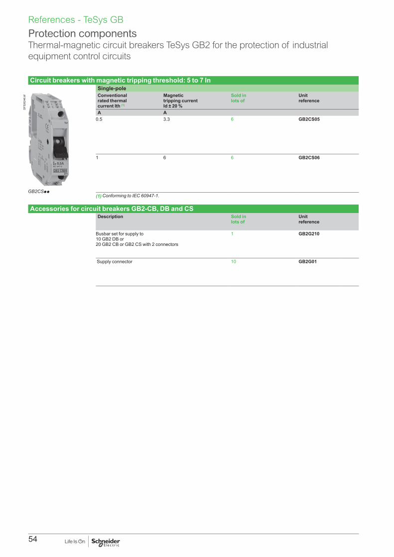
54
References - TeSys GB
Circuit breakers with magnetic tripping threshold: 5 to 7 InSingle-poleConventional rated thermal current Ith (1)
Magnetic tripping current Id ± 20 %
Sold in lots of
Unit reference
A A0.5 3.3 6 GB2CS05
1 6 6 GB2CS06
(1) Conforming to IEC 60947-1.
Accessories for circuit breakers GB2-CB, DB and CSDescription Sold in
lots ofUnit reference
Busbar set for supply to 10 GB2 DB or 20 GB2 CB or GB2 CS with 2 connectors
1 GB2G210
Supply connector 10 GB2G01
Protection componentsThermal-magnetic circuit breakers TeSys GB2 for the protection of industrial equipment control circuits
GB2CSpp
DF5
2624
6.tif
55
Technical Data for Designers
TeS
ys G
V, G
B
ContentsTeSys GV2: > characteristics ............................................... 58 to 62 > curves ............................................................ 63 to 72 > accessories .................................................... 75 to 77 > dimensions, schemes .................................... 76 to 85
TeSys GV3: > characteristics ............................................... 88 to 91 > curves ............................................................ 92 to 97 > accessories ................................................ 100 to 102 > dimensions, schemes ................................ 101 to 103
TeSys GV4: > characteristics ........................................... 106 to 118 > curves ........................................................ 111 to 115 > accessories ................................................ 121 to 122 > dimensions ................................................ 120 to 122
TeSys GV7: > characteristics ...................................................... 126 > curves ........................................................ 127 to 131 > accessories ................................................ 134 to 135 > dimensions, schemes ................................ 134 to 137
TeSys GVB2: > characteristics ........................................... 140 to 142 > dimensions, schemes ........................................... 143

56
57
TeSys GV20.06 to 15 kW
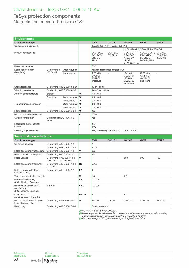
58
Characteristics - TeSys GV2 - 0.06 to 15 Kw
TeSys protection componentsMagnetic motor circuit breakers GV2
EnvironmentCircuit breaker type GV2L GV2LE GV2ME GV2P GV2 RTConforming to standards IEC/EN 60947-4-1, IEC/EN 60947-2
UL60947-4-1 (1), CSA C22.2 n°60947-4-1Product certifications CCC, EAC,
BV, LROS,DNV-GL, RINA
CCC, EAC, BV, RINA
CCC, UL, CSA, EAC, ATEX, BV, LROS, DNV-GL, RINA
CCC, UL, CSA, EAC, ATEX, BV, LROS, DNV-GL, RINA
CCC, UL, CSA, EAC, BV, LROS
Protective treatment "TH"
Degree of protection (front face)
Conforming to IEC 60529
Open mounted Against direct finger contact: IP20In enclosure IP65 with
GV2PC01GV2PC02 enclosure
- IP41 withGV2Mp01IP55 withGV2Mp02enclosure
IP 65 withGV2PC01GV2PC02 enclosure
-
Shock resistance Conforming to IEC 60068-2-27 30 gn - 11 msVibration resistance Conforming to IEC 60068-2-6 5 gn (5 to 150 Hz)Ambient air temperature Storage °C -40…+80
Operation Open mounted °C -20…+60In enclosure °C -20…+40
Temperature compensation Open mounted °C -20…+60In enclosure °C -20…+40
Flame resistance Conforming to IEC 60695-2-1 °C 960Maximum operating altitude m 2000Suitable for isolation Conforming to IEC 60947-1 §
7-1-6Yes
Resistance to mechanical impact
J 0.5IK04
Sensitivy to phase failure Yes, conforming to IEC 60947-4-1 § 7-2-1-5-2
Technical characteristicsCircuit breaker type GV2L GV2LE GV2ME GV2P GV2RTUtilisation category Conforming to IEC 60947-2 A
Conforming to IEC 60947-4-1 AC-3Rated operational voltage (Ue) Conforming to IEC 60947-2 V 690Rated insulation voltage (Ui) Conforming to IEC 60947-2 V 690Rated voltage Conforming to UL 60947-4-1,
CSA C 22.2 n° 60947-4-1V - - 600 600 600
Rated operational frequency Conforming to IEC 60947-4-1 UL, CSA
Hz 50/60
Rated impulse withstand voltage (U imp)
Conforming to IEC 60947-2 kV 6
Total power dissipated per pole W 1.8 2.5Mechanical durability (C.O.: Closing, Opening)
C.O. 100 000
Electrical durability for AC-3/415V duty (C.O.: Closing, Opening)
415 V In C.O. 100 000
Duty class (maximum operating rate)
C.O./h 40 25
Maximum conventional rated thermal current (Ith)
Conforming to IEC 60947-4-1 A 0.4...32 0.4...32 0.16...32 0.16...32 0.40...23
Rated duty Conforming to IEC 60947-4-1 Continuous duty
(1) UL 60947-4-1 type E for GV2PppH7.(2) Leave a space of 9 mm between 2 circuit breakers: either an empty space, or side mounting
add-on contact blocks. Side by side mounting is possible up to 40 °C.(3) For operation up to 70 °C, please consult your Regional Sales Office.
References:pages 9 to 20
Curves:pages 63 to 72
Dimensions:pages 76 to 85

59
Characteristics - TeSys GV2 - 0.06 to 15 Kw
TeSys protection componentsMagnetic motor circuit breakers GV2
Mounting characteristicsOperating position Without derating, in relation to normal vertical mounting plane (1) 90
˚ 90˚90˚ 90˚
DF5
1052
0.ep
s
Connection characteristicsConnection to screw clamp terminals or spring terminals
Bare cables
h
DF5
1055
4.ep
sCircuit breaker type GV2L GV2LE GV2ME GV2P GV2RT
Connection to screw clamp terminals (2) (Max. number of conductors x c.s.a.)
Min. Max. Min. Max. Min. Max. Min. Max. Min. Max.Solid cable mm2 2 x 1 2 x 6 2 x 1 2 x 6 2 x 1 2 x 6 2 x 1 2 x 6 2 x 1 2 x 6Flexible cable without cable end
mm2 2 x 1.5 2 x 6 2 x 1.5 2 x 6 2 x 1.5 2 x 6 2 x 1.5 2 x 6 2 x 1.5 2 x 6
Flexible cable with cable end
mm2 2 x 1 2 x 4 2 x 1 2 x 4 2 x 1 2 x 4 2 x 1 2 x 4 2 x 1 2 x 4
Tightening torque N.m 1.7Connection to spring terminals Number of conductors x c.s.a.
Solid cable mm2 – – – – 2 x 1 (3) 2 x 6 – – – –Flexible cable without cable end
mm2 – – – – 2 x 1.5 (3)
2 x 4 – – – –
Connection by bars or lugsBars or lugs
e
d
L
DF5
3404
6.ep
s
d
L
DF5
3404
7.ep
s
L'
Ø6DF5
1061
5.ep
s
Circuit breaker type GV2MEpp6Pitch Without spreaders mm 13.5
With spreaders mm –Bars or cables with lugs e mm y 6
L mm y 9.5L’ mm y 9.5d mm y 10
Screws M4Tightening torque N.m 1.7
Bare cables (copper or aluminium) with connectors
Height (h) mm –C.s.a. mm2 –Tightening torque N.m –
(1) When mounting on a vertical rail, fit a stop to prevent any slippage.(2) For motor circuit breakers GV3P: BTR hexagon socket head screws, EverLink® system.
Require use of an insulated Allen key, in compliance with local electrical wiring regulations.(3) For cross-sections 1 to 1.5 mm2, the use of an LA9D99 cable end reducer is recommended.
References:pages 9 to 20
Curves:pages 63 to 72
Dimensions:pages 76 to 85
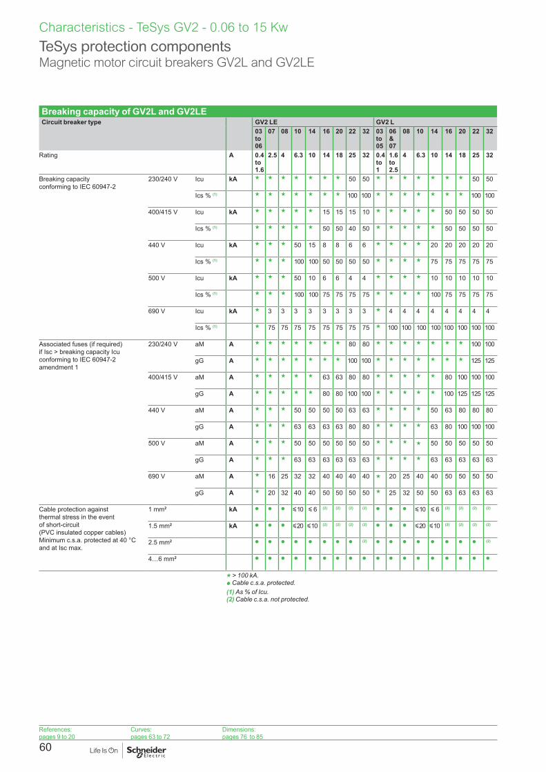
60
Breaking capacity of GV2L and GV2LECircuit breaker type GV2 LE GV2 L
03 to 06
07 08 10 14 16 20 22 32 03 to 05
06 &07
08 10 14 16 20 22 32
Rating A 0.4 to 1.6
2.5 4 6.3 10 14 18 25 32 0.4 to 1
1.6 to 2.5
4 6.3 10 14 18 25 32
Breaking capacity conforming to IEC 60947-2
230/240 V Icu kA g g g g g g g 50 50 g g g g g g g 50 50
Ics % (1) g g g g g g g 100 100 g g g g g g g 100 100
400/415 V Icu kA g g g g g 15 15 15 10 g g g g g 50 50 50 50
Ics % (1) g g g g g 50 50 40 50 g g g g g 50 50 50 50
440 V Icu kA g g g 50 15 8 8 6 6 g g g g 20 20 20 20 20
Ics % (1) g g g 100 100 50 50 50 50 g g g g 75 75 75 75 75
500 V Icu kA g g g 50 10 6 6 4 4 g g g g 10 10 10 10 10
Ics % (1) g g g 100 100 75 75 75 75 g g g g 100 75 75 75 75
690 V Icu kA g 3 3 3 3 3 3 3 3 g 4 4 4 4 4 4 4 4
Ics % (1) g 75 75 75 75 75 75 75 75 g 100 100 100 100 100 100 100 100
Associated fuses (if required) if Isc > breaking capacity Icu conforming to IEC 60947-2 amendment 1
230/240 V aM A g g g g g g g 80 80 g g g g g g g 100 100
gG A g g g g g g g 100 100 g g g g g g g 125 125
400/415 V aM A g g g g g 63 63 80 80 g g g g g 80 100 100 100
gG A g g g g g 80 80 100 100 g g g g g 100 125 125 125
440 V aM A g g g 50 50 50 50 63 63 g g g g 50 63 80 80 80
gG A g g g 63 63 63 63 80 80 g g g g 63 80 100 100 100
500 V aM A g g g 50 50 50 50 50 50 g g g g 50 50 50 50 50
gG A g g g 63 63 63 63 63 63 g g g g 63 63 63 63 63
690 V aM A g 16 25 32 32 40 40 40 40 g 20 25 40 40 50 50 50 50
gG A g 20 32 40 40 50 50 50 50 g 25 32 50 50 63 63 63 63
Cable protection against thermal stress in the event of short-circuit (PVC insulated copper cables) Minimum c.s.a. protected at 40 °C and at Isc max.
1 mm2 kA p p p y 10 y 6 (2) (2) (2) (2) p p p y 10 y 6 (2) (2) (2) (2)
1.5 mm2 kA p p p y 20 y 10 (2) (2) (2) (2) p p p y 20 y 10 (2) (2) (2) (2)
2.5 mm2 p p p p p p p p (2) p p p p p p p p (2)
4…6 mm2 p p p p p p p p p p p p p p p p p p
g > 100 kA.p Cable c.s.a. protected.(1) As % of Icu.(2) Cable c.s.a. not protected.
Characteristics - TeSys GV2 - 0.06 to 15 Kw
TeSys protection componentsMagnetic motor circuit breakers GV2L and GV2LE
References:pages 9 to 20
Curves:pages 63 to 72
Dimensions:pages 76 to 85

61
Characteristics - TeSys GV2 - 0.06 to 15 Kw
TeSys protection componentsThermal-magnetic motor circuit breakers GV2ME and GV2P
Breaking capacity of GV2ME and GV2PCircuit breaker type GV2 ME GV2 P
01 to 06
07 08 10 14 16 20 21 & 22
32 01 to 06
07 08 10 14 16 20 21 & 22
32
Rating A 0.1 to 1.6
2.5 4 6.3 10 14 18 23 & 25
32 0.1 to 1.6
2.5 4 6.3 10 14 18 23 & 25
32
Breaking capacity conforming to IEC 60947-2
230/240 V Icu kA g g g g g g g 50 50 g g g g g g g g g
Ics % (1) g g g g g g g 100 100 g g g g g g g g g
400/415 V Icu kA g g g g g 15 15 15 10 g g g g g g 50 50 50
Ics % (1) g g g g g 50 50 40 50 g g g g g g 50 50 50
440 V Icu kA g g g 50 15 8 8 6 6 g g g g g 50 20 20 20
Ics % (1) g g g 100 100 50 50 50 50 g g g g g 75 75 75 75
500 V Icu kA g g g 50 10 6 6 4 4 g g g g 50 42 10 10 10
Ics % (1) g g g 100 100 75 75 75 75 g g g g 100 75 75 75 75
690 V Icu kA g 3 3 3 3 3 3 3 3 g 8 8 6 6 6 4 4 4
Ics % (1) g 75 75 75 75 75 75 75 75 g 100 100 100 100 100 100 100 100
Associated fuses (if required) if Isc > breaking capacity Icu conforming to IEC 60947-2
230/240 V aM A g g g g g g g 80 80 g g g g g g g g g
gG A g g g g g g g 100 100 g g g g g g g g g
400/415 V aM A g g g g g 63 63 80 80 g g g g g g 100 100 100
gG A g g g g g 80 80 100 100 g g g g g g 125 125 125
440 V aM A g g g 50 50 50 50 63 63 g g g g g 50 63 80 80
gG A g g g 63 63 63 63 80 80 g g g g g 63 80 100 100
500 V aM A g g g 50 50 50 50 50 50 g g g g 50 50 50 50 50
gG A g g g 63 63 63 63 63 63 g g g g 63 63 63 63 63
690 V aM A g 16 25 32 32 40 40 40 40 g 20 25 40 40 50 50 50 50
gG A g 20 32 40 40 50 50 50 50 g 25 32 50 50 63 63 63 63
g > 100 kA.(1) As % of Icu.
References:pages 9 to 20
Curves:pages 63 to 72
Dimensions:pages 76 to 85

62
Breaking capacity of GV2ME and GV2P (used in association with current limiter GV1L3)Circuit breaker type GV2ME
01 to 06 07 08 10 14 16 20 21 22 32Rating A 0.1 to
1.62.5 4 6.3 10 14 18 23 25 32
Breaking capacity conforming to IEC 60947-2
230/240 V Icu kA g g g g g g g g g g
Ics % (1) g g g g g g g g g g
400/415 V Icu kA g g g g g 100 100 100 100 100
Ics % (1) g g g g g 50 50 40 40 40
440 V Icu kA g g g g g 50 20 20 20 20
Ics % (1) g g g g g 75 75 75 75 75
500 V Icu kA g g g g 50 42 10 10 10 10
Ics % (1) g g g g 100 100 75 75 75 75
Circuit breaker type GV2P01 to 06 07 08 10 14 16 20 21 22 32
Rating A 0.1 to 1.6
2.5 4 6.3 10 14 18 23 25 32
Breaking capacity conforming to IEC 60947-2
230/240 V Icu kA g g g g g g g g g g
Ics % (1) g g g g g g g g g g
400/415 V Icu kA g g g g g g g g g g
Ics % (1) g g g g g g g g g g
440 V Icu kA g g g g g 100 100 100 100 100
Ics % (1) g g g g g 50 50 50 50 50
500 V Icu kA g g g g 100 100 100 100 100 100
Ics % (1) g g g g 50 50 50 50 50 50
690 V (3) Icu = Ics kA g 50 50 50 50 50 50 50 50 50
Circuit breaker type GV2ME01 to 06 07 08 10 14 16 20 21 22 32
Rating A 0.1 to 1.6
2.5 4 6.3 10 14 18 23 25 32
Cable protection against thermal stress in the event of short-circuit (PVC insulated copper cables)
Minimum c.s.a. protected at 40 °C at Isc max.
1 mm2 p p p y 10 kA y 6 kA (2) (2) (2) (2) (2)
1.5 mm2 p p p y 20 kA y 10 kA (2) (2) (2) (2) (2)
2.5 mm2 p p p p p p p p p (2)
4…6 mm2 p p p p p p p p p p
g > 100 kA.p Cable c.s.a. protected.(1) As % of Icu.(2) Cable c.s.a. not protected.(3) With limiter LA9LB920.
Characteristics - TeSys GV2 - 0.06 to 15 Kw
TeSys protection componentsThermal-magnetic motor circuit breakers GV2 ME and GV2P
References:pages 9 to 20
Curves:pages 63 to 72
Dimensions:pages 76 to 85

63
Curves - TeSys GV2 - 0.06 to 15 kW
Tripping curves for GV2L or LE combined with thermal overload relay LRD or LR2KAverage operating times at 20 °C related to multiples of the setting current
10
10 000
1
0,1
0,0011 10 100
1000
100
0,01
321
Time (s)
x the setting current (Ir)
DF5
3409
2R.e
ps
1 3 poles from cold state2 2 poles from cold state3 3 poles from hot state
TeSys protection componentsMagnetic motor circuit breakers GV2L and GV2LE
References:pages 9 to 20
Characteristics:pages 58 to 62
Dimensions:pages 76 to 85

64
Current limitation on short-circuit for GV2L and GV2LE only (3-phase 400/415 V)Dynamic stress
I peak = f (prospective Isc) at 1.05 Ue = 435 V
100
10
1
0,10,1 1 100
1
5
4
3
8
9
10
7
6
cos
= 0
.95
= 0.
9
= 0.
8
= 0.7
= 0.
5
= 0.
3
= 0.
25
151011
2
Limited peak current (kA)
Prospective Isc (kA)
DF5
3409
3.ep
s
1 Maximum peak current2 32 A3 25 A4 18 A5 14 A6 10 A7 6.3 A8 4 A9 2.5 A10 1.6 A11 Limit of rated ultimate breaking capacity on short-circuit of GV2LE (14, 18, 23 and 25 A ratings).
Curves - TeSys GV2 - 0.06 to 15 kW
TeSys protection componentsMagnetic motor circuit breakers GV2L and GV2LE
References:pages 9 to 20
Characteristics:pages 58 to 62
Dimensions:pages 76 to 85

65
Curves - TeSys GV2 - 0.06 to 15 kW
TeSys protection componentsMagnetic motor circuit breakers GV2L and GV2LE
Current limitation on short-circuit for GV2L and GV2LE + thermal overload relay LRD or LR2K (3-phase 400/415 V)Dynamic stress
I peak = f (prospective Isc) at 1.05 Ue = 435 V
100
10
1
0,10,1 1 10 100
cos
= 0
.95
= 0.
9
= 0.
8
= 0.
7=
0.5
= 0.
3
= 0.
25
15 11
1
2
3
4
5
6
7
8
9
10
Limited peak current (kA)
Prospective Isc (kA)
DF5
3409
4.ep
s
1 Maximum peak current2 32 A3 25 A4 18 A5 14 A6 10 A7 6.3 A8 4 A9 2.5 A10 1.6 A11 Limit of rated ultimate breaking capacity on short-circuit of GV2LE (14, 18, 23 and 25 A ratings).
References:pages 9 to 20
Characteristics:pages 58 to 62
Dimensions:pages 76 to 85

66
Thermal limit on short-circuit for GV2LE onlyThermal limit in kA2s in the magnetic operating zone
Sum of I2dt = f (prospective Isc) at 1.05 Ue = 435 V
100
10
1
0,1
0,010,1 1 10 100
1 2
3
4
5
6
7
8
9
Sum of I2dt (kA2s)
Prospective Isc (kA)
DF5
3409
5.ep
s
1 32 A2 25 A3 18 A4 14 A5 10 A6 6.3 A7 4 A8 2.5 A9 1.6 A
Curves - TeSys GV2 - 0.06 to 15 kW
TeSys protection componentsMagnetic motor circuit breakers GV2LE
References:pages 9 to 20
Characteristics:pages 58 to 62
Dimensions:pages 76 to 85

67
Curves - TeSys GV2 - 0.06 to 15 kW
TeSys protection componentsMagnetic motor circuit breakers GV2L
Thermal limit on short-circuit for GV2L onlyThermal limit in kA2s in the magnetic operating zone
Sum of I2dt = f (prospective Isc) at 1.05 Ue = 435 V
100
10
1
0,1
0,010,1 1 10 100
1234
5
6
8
7
Sum of I2dt (kA2s)
Prospective Isc (kA)
DF5
3409
6.ep
s
1 25 A and 32 A2 18 A3 14 A4 10 A5 6.3 A6 4 A7 2.5 A8 1.6 A
References:pages 9 to 20
Characteristics:pages 58 to 62
Dimensions:pages 76 to 85
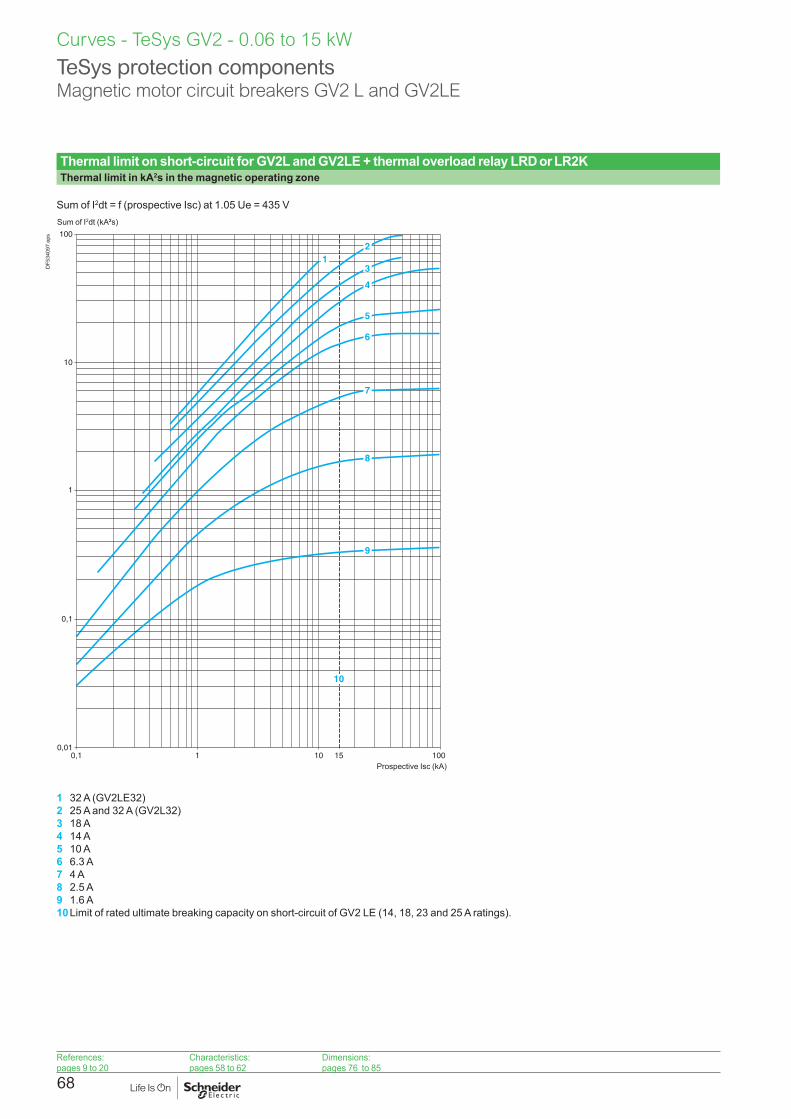
68
Thermal limit on short-circuit for GV2L and GV2LE + thermal overload relay LRD or LR2KThermal limit in kA2s in the magnetic operating zone
Sum of I2dt = f (prospective Isc) at 1.05 Ue = 435 V
100
10
1
0,1
0,010,1 1 10 100
2
3
4
5
6
7
8
9
15
1
10
Sum of I2dt (kA2s)
Prospective Isc (kA)
DF5
3409
7.ep
s
1 32 A (GV2LE32)2 25 A and 32 A (GV2L32)3 18 A4 14 A5 10 A6 6.3 A7 4 A8 2.5 A9 1.6 A10 Limit of rated ultimate breaking capacity on short-circuit of GV2 LE (14, 18, 23 and 25 A ratings).
Curves - TeSys GV2 - 0.06 to 15 kW
TeSys protection componentsMagnetic motor circuit breakers GV2 L and GV2LE
References:pages 9 to 20
Characteristics:pages 58 to 62
Dimensions:pages 76 to 85

69
Curves - TeSys GV2 - 0.06 to 15 kW
TeSys protection componentsThermal-magnetic motor circuit breakers GV2ME and GV2P
Thermal-magnetic tripping curves for GV2ME and GV2PAverage operating times at 20 °C related to multiples of the setting current
0,001
0,1
1
10
100
0,01
1 1,5 10 100
1000
10 000
3
2
1
Time (s)
x the setting current (Ir)
DF5
3407
5R.a
i
1 3 poles from cold state2 2 poles from cold state3 3 poles from hot state
References:pages 9 to 20
Characteristics:pages 58 to 62
Dimensions:pages 76 to 85

70
Current limitation on short-circuit for GV2ME and GV2P (3-phase 400/415 V)Dynamic stress
I peak = f (prospective Isc) at 1.05 Ue = 435 V
1
6
5
4
3
7
8
9
10
11
2
100
10
1
0,10,1 1 10 100
cos
= 0
.95
= 0.
9
= 0.
8
= 0.
7=
0.5
= 0.
3
= 0.
25
15 (12)
Limited peak current (kA)
Prospective Isc (kA)
DF5
3407
6.ep
s
1 Maximum peak current2 24 -32 A3 20 -25 A4 17 -23 A5 13 -18 A6 9 -14 A7 6 -10 A8 4 -6.3 A9 2.5 -4 A10 1.6 -2.5 A11 1 -1.6 A12 Limit of rated ultimate breaking capacity on short-circuit of GV2ME (14, 18, 23 and 25 A ratings)
Curves - TeSys GV2 - 0.06 to 15 kW
TeSys protection componentsThermal-magnetic motor circuit breakers GV2ME and GV2P
References:pages 9 to 20
Characteristics:pages 58 to 62
Dimensions:pages 76 to 85

71
Curves - TeSys GV2 - 0.06 to 15 kW
TeSys protection componentsThermal-magnetic motor circuit breakers GV2ME
Thermal limit on short-circuit for GV2METhermal limit in kA2s in the magnetic operating zone
Sum of I2dt = f (prospective Isc) at 1.05 Ue = 435 V
100
10
1
0,1
0,010,1 1 10 100
345
6
7
8
9
10
21
Sum of I2dt (kA2s)
Prospective Isc (kA)
DF5
3407
7.ep
s
1 24 -32 A2 20 -25 A3 17 -23 A4 13 -18 A5 9 -14 A6 6 -10 A7 4 -6.3 A8 2.5 -4 A9 1.6 -2.5 A10 1 -1.6 A
References:pages 9 to 20
Characteristics:pages 58 to 62
Dimensions:pages 76 to 85

72
Thermal limit on short-circuit for GV2PThermal limit in kA2s in the magnetic operating zone
Sum of I2dt = f (prospective Isc) at 1.05 Ue = 435 V
100
10
1
0,1
0,010,1 1 10 100
123
4
5
6
7
8
9
Sum of I2dt (kA2s)
Prospective Isc (kA)
DF5
3407
8.ep
s
1 24 -32 A1 20 -25 A2 17 -23 A3 13 -18 A4 9 -14 A5 6 -10 A6 4 -6.3 A7 2.5 -4 A8 1.6 -2.5 A9 1 -1.6 A
Curves - TeSys GV2 - 0.06 to 15 kW
TeSys protection componentsThermal-magnetic motor circuit breakers GV2P
References:pages 9 to 20
Characteristics:pages 58 to 62
Dimensions:pages 76 to 85
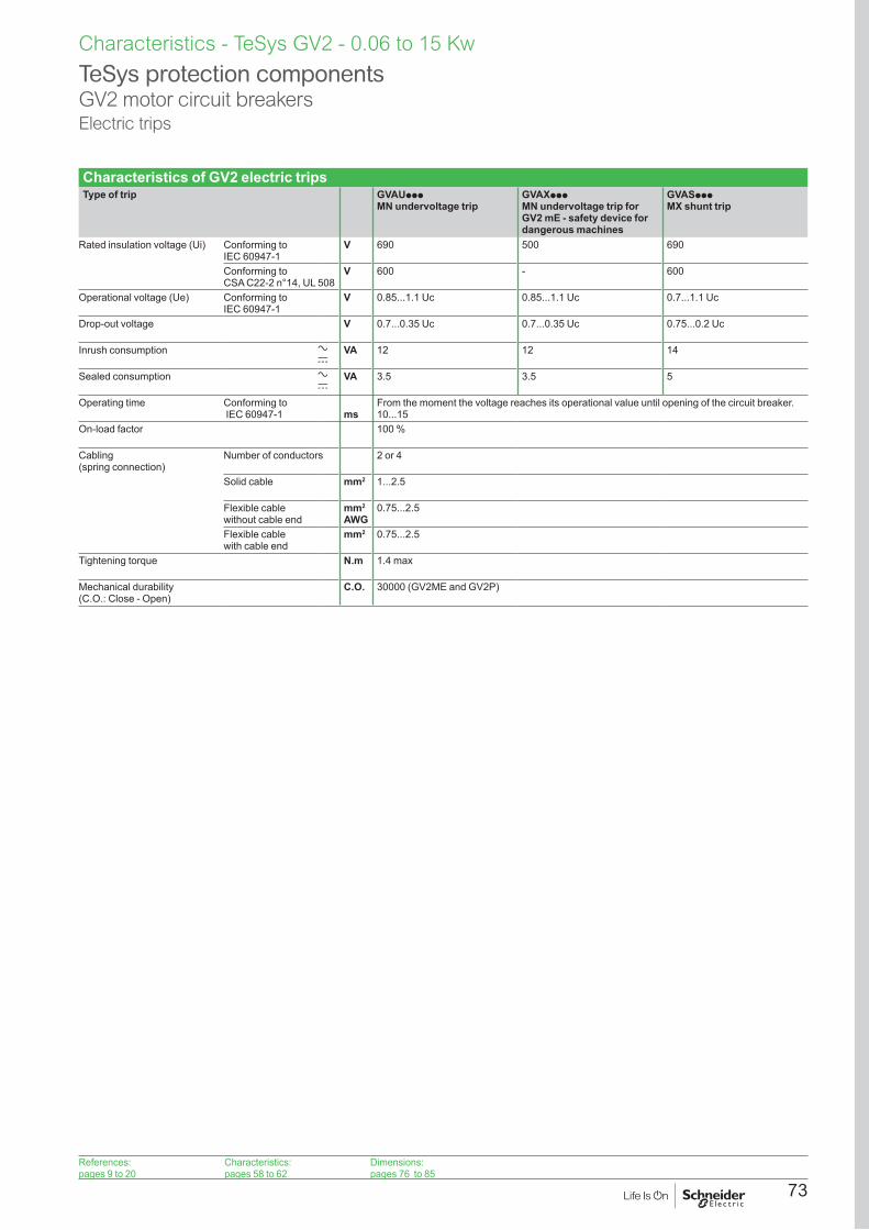
73
Characteristics of GV2 electric tripsType of trip GVAUppp
MN undervoltage tripGVAXpppMN undervoltage trip for GV2 mE - safety device for dangerous machines
GVASppp MX shunt trip
Rated insulation voltage (Ui) Conforming to IEC 60947-1
V 690 500 690
Conforming to CSA C22-2 n°14, UL 508
V 600 - 600
Operational voltage (Ue) Conforming to IEC 60947-1
V 0.85...1.1 Uc 0.85...1.1 Uc 0.7...1.1 Uc
Drop-out voltage V 0.7...0.35 Uc 0.7...0.35 Uc 0.75...0.2 Uc
Inrush consumption a c
VA 12 12 14
Sealed consumption a c
VA 3.5 3.5 5
Operating time Conforming to IEC 60947-1 ms
From the moment the voltage reaches its operational value until opening of the circuit breaker. 10...15
On-load factor 100 %
Cabling (spring connection)
Number of conductors 2 or 4
Solid cable mm2 1...2.5
Flexible cable without cable end
mm2
AWG0.75...2.5
Flexible cable with cable end
mm2 0.75...2.5
Tightening torque N.m 1.4 max
Mechanical durability (C.O.: Close - Open)
C.O. 30000 (GV2ME and GV2P)
TeSys protection componentsGV2 motor circuit breakersElectric trips
Characteristics - TeSys GV2 - 0.06 to 15 Kw
References:pages 9 to 20
Characteristics:pages 58 to 62
Dimensions:pages 76 to 85

74
Characteristics - TeSys GV2 - 0.06 to 15 Kw
Type of contacts Instantaneous auxiliary GVAN, GVAD
Fault signalling GVAD, GVAM11 (1)
Instantaneous auxiliary GVAE
Rated insulation voltage (Ui) (associated insulation coordination)
Conforming to IEC 60947-1 V 690 690 250 (690 in relation to main circuit)
Conforming to CSA C22-2 n° 14 and UL 508
V 600 300 300
Conventional thermal current (Ith)
Conforming to IEC 60947-5-1 A 6 2.5 2.5
Conforming to CSA C22-2 n° 14 and UL 508
A 5 1 1
Mechanical durability (C.O.: Close - Open)
C.O. 100 000 1000 100 000
Operational power and current conforming to IEC 60947-5-1. a.c. operation
AC-15/100 000 C.O. AC-14/1000 C.O. AC-15/100 000 C.O.
Rated operational voltage (Ue)
V 48 110 127
230 240
380 415
440 500 690 24 48 110 127
230 240
24 48 110 127
230 240
Operation Operational power, normal conditions
VA 300 500 720 850 650 500 400 36 48 72 72 48 60 120 120
Occasional breaking and making capacities, abnormal conditions
kVA 3 7 13 15 13 12 9 0.22 0.3 0.45 0.45 0.48 0.6 1.27 2.4
Rated operational current (Ie)
A 6 4.5 3.3 2.2 1.5 1 0.6 1.5 1 0.5 0.3 2 1.25 1 0.5
Operational power and current conforming to IEC 60947-5-1. d.c.
DC-13/100 000 C.O. DC-13/1000 C.O. DC-13/100 000 C.O.
Rated operational voltage (Ue)
V 24 48 60 110 240(2)
– – 24 48 60 – 24 48 60 –
Operation Operational power, normal conditions
W 140 240 180 140 120 – – 24 15 9 – 24 15 9 –
Occasional breaking and making capacities, abnormal conditions
W 240 360 240 210 180 – – 100 50 50 – 100 50 50 –
Rated operational current (Ie)
A 6 5 3 1.3 0.5 – – 1 0.3 0.15 – 1 0.3 0.15 –
Low power switching reliability of contact GV AE: Number of failures for “n” million operating cycles (17 V-5 mA): = 10-6
Minimum operational conditions d.c. operation
V 17mA 5
Short-circuit protection By GB2 CBpp circuit breaker (rating according to operational current for Ue y 415 V) or by gG fuse 10 A max
GB2 CB06 or gG fuse 10 A max
Cabling, screw clamp terminals Number of conductors 1 2Solid cable mm2 1…2.5 1…2.5Flexible cable without cable end mm2 0.75…2.5 0.75…2.5Flexible cable with cable end mm2 0.75…1.5 0.75…1.5Tightening torque N.m 1.4 max 1.4 max
Cabling, spring terminal connections
GV AN onlyFlexible cable without cable end mm2 0.75…2.5 0.75…2.5 – 0.75…1.5
Operation of instantaneous auxiliary contactsGV3P, GV3L
0 1Power pole
GV AN20 FF
GV AN11 FO
GV AE1 FO
GV AE20 FF
GV AE11 FO
GV AD10pp FO
GV AED101 FGV AED011 O
GV20 1
Power pole
GV AN20 FF
GV AN11 FO
GV AE1 FO
GV AE20 FF
GV AE11 FO
GV AD10pp FGV AD11pp O
Contact open Contact Close
DB4
0239
9.ep
s
Operation of fault signalling contacts
GVAM11Change of state following tripping on short-circuit.
GVAD10pp and GVAD01ppChange of state following tripping on short-circuit, overload or undervoltage.
(1) For application example of fault signalling contact and short-circuit signalling contact, see page 114.(2) Add an RC circuit type LA4 D to the load terminals, see page 114.
TeSys protection componentsThermal-magnetic motor circuit breakers GV2Auxiliary contacts
References:pages 9 to 20
Characteristics:pages 58 to 62
Dimensions:pages 76 to 85

75
Characteristics - TeSys GV2 - 0.06 to 15 Kw
Characteristics of 3-pole busbars GV2GpppGV2Gppp
Rated insulation voltage (Ui) Conforming to IEC 60947-1 V 690
Conventional thermal current (Ith)
Conforming to IEC 60439-1 A 63
Rated operational current (Ie) A 63
Permissible peak current (I peak)
kA 11
Permissible thermal limit (I2t)
kA2s 104
Degree of protection Conforming to IEC 60529 IP 20
Terminal block Yes
Characteristics of terminal blocks GV2G05 and GV1G09 (for GV2ME and GV2P)Rated insulation voltage (Ui) Conforming to IEC 60947-1 V 690
Conventional thermal current (Ith)
Conforming to IEC 60439-1 A 63
Rated operational current (Ie) A 63 115
Degree of protection Conforming to IEC 60529 IP 20
Connection Solid cable mm2 1 x 1.5 to 25 conductor or 2 x 1.5 to 6 conductors
Flexible cable without cable end mm2 1 x 1.5 to 16 conductor or 2 x 1.5 to 4 conductors
Flexible cable with cable end mm2 1 x 1.5 to 10 conductor or 2 x 1.5 to 2 conductors
Flexible or solid cable AWG 1 AWG 4
Tightening torque Connector N.m 2.2
Screw clamp terminals N.m 1.7
Characteristics of current limiters (GV2ME and GV2P)Type GV1L3 LA9LB920
Rated insulation voltage (Ui) Conforming to IEC 60947-1 V 690 690
Conventional thermal current (Ith)
Conforming to IEC 60947-1 A 63 63
Rated operational current(Ie)
A 32 32
Operating threshold rms current A 1500 (non adjustable threshold) 1000 (non adjustable threshold)
Connection 1 conductor 2 conductors 1 conductor 2 conductors
Solid cable mm2 1.5…25 1.5…10 1.5…25 1.5…10
Flexible cable without cable end mm2 1.5…25 2.5…10 1.5…25 1.5…10
Flexible cable with cable end mm2 1.5…16 1.5… 4 1.5…16 1.5… 4
Tightening torque N.m 2.2
TeSys protection componentsThermal-magnetic and magnetic motor circuit breakers GV2Accessories
References:pages 9 to 20
Characteristics:pages 58 to 62
Dimensions:pages 76 to 85

76
Dimensions, mounting - TeSys GV2 - 0.06 to 15 kW
GV2LDimensions GVAD, AM, AN, AU, AS GV2AK00
44,5 9,3 9,381 (1)
1818
89
82
X1
5026
X2
15
6145=
=
Block GVAD, AM, ANBlock GVAU, AS
DF5
3743
8.ep
s 9814
44,5
32DF5
3743
9.ep
s
X1 Electrical clearance = 40 mm for Ue y 415 V, or 80 mm for Ue = 440 V, or 120 mm for Ue = 500 and 690 V.X2 = 40 mm.
(1) Maximum.
Mounting Adapter plate GK2AF01On rail AM1 DE200, AM1 ED200 (35 x 15)
Panel mounted On pre-slotted mounting plate AM1 PA
13,5
84
44,5
44,5
106
45
35
54
105±
5
35
Ø5,5
5
AF1 EA484
13,5 24
5545
135
9,5
DF5
3744
0.ep
s
7.5 mm height compensation plate GV1F03
39
3513
DF5
3744
1.ep
s
GV2LEDimensions GVAD, AM, AN, AU, AS GVAE
44
89
167,56612,5
X1
X1 44,5
45=
=
DF5
3744
2.ep
s
9,3 9,3 1881 (1)
Block GV AD, AM, ANBlock GV AU, AS
DF5
3747
7.ep
s
15
10
DF5
3744
3.ep
s
X1 Electrical clearance = 40 mm for Ue y 690 V. (1) Maximum.MountingOn 35 mm 7 rail On panel with adapter plate GV2 AF02 On pre-slotted plate AM1 PA On rails DZ5 MB201
c
44,5
44,5
DF5
3744
4.ep
s
84,54,235
50/6
0
DF5
3744
5.ep
s AF1 EA4
35
50/6
0
DF5
3744
6.ep
s 15 35
50 60
DZ5 MB201GV2 AF02DZ5 ME8
DF5
3744
7.ep
s
c = 80 on AM1 DP200 (35 x 7.5) and 88 on AM1 DE200, ED200 (35 x15)
TeSys protection componentsMagnetic motor circuit breakers GV2L and GV2LE
References:pages 9 to 20
Characteristics:pages 58 to 62
Curves:pages 63 to 72
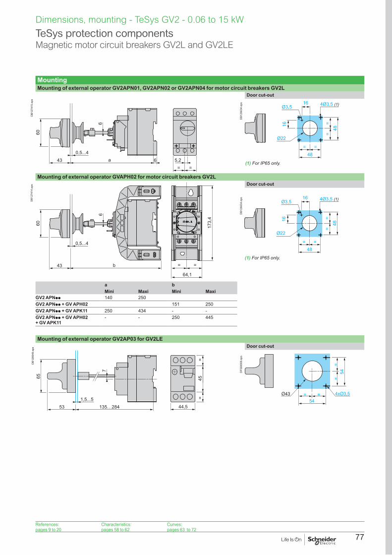
77
MountingMounting of external operator GV2APN01, GV2APN02 or GV2APN04 for motor circuit breakers GV2L
5,2= =
0,5...4
6
43 6a
60D
B127
415.
eps
Door cut-out
(1) For IP65 only.
48= =
==
48
4Ø3,5 (1)16
16
Ø3,5
Ø22
DB1
2663
4.ep
s
Mounting of external operator GVAPH02 for motor circuit breakers GV2L
0,5...4
6
43 b
60
64,1
173,
4
= =
DB1
2741
4.ep
s Door cut-out
(1) For IP65 only.
48= =
==
48
4Ø3,5 (1)16
16
Ø3,5
Ø22D
B126
634.
eps
a bMini Maxi Mini Maxi
GV2 APNpp 140 250GV2 APNpp + GV APH02 151 250GV2 APNpp + GV APK11 250 434 - -GV2 APNpp + GV APH02 + GV APK11
- - 250 445
Mounting of external operator GV2AP03 for GV2LE
1,5...5
7
53 135…284
65 45=
=
44,5
DB1
2664
9.ep
s Door cut-out
=54
=
==
54DF5
6900
8.ep
s
Dimensions, mounting - TeSys GV2 - 0.06 to 15 kW
TeSys protection componentsMagnetic motor circuit breakers GV2L and GV2LE
References:pages 9 to 20
Characteristics:pages 58 to 62
Curves:pages 63 to 72

78
Dimensions, mounting - TeSys GV2 - 0.06 to 15 kW
TeSys protection componentsMagnetic motor circuit breakers GV2L and GV2LE
GV2L and GV2LESets of busbars GV2G445, GV2G454, GV2G472, with terminal block GV2G05
63
l3a
18
p
45
DF5
3745
1.ep
s
l pGV2G445 (4 x 45 mm) 179 45GV2G454 (4 x 54 mm) 206 54GV2G472 (4 x 72 mm) 260 72
aNumber of tap-offs 5 6 7 8
GV2G445 224 269 314 359GV2G454 260 314 368 422GV2G472 332 404 476 548
Sets of busbars for GV2L and GV2LE Sets of busbars GV2Gppp with term. block GV1G09 Sets of busbars GV2G245, GV2G254, GV2GR272
GV1 G09
30
DF5
3745
2.ep
s l
DF5
3745
3.ep
s
IGV2G245 (2 x 45 mm) 89GV2G254 (2 x 54 mm) 98GV2G272 (2 x 72 mm) 116
Set of busbars GV2G554 Sets of busbars GV2G345 and GV2G354260
DF5
3745
4.ep
s l
DF5
3745
5.ep
s
IGV2G345 (3 x 45 mm) 134GV2G354 (3 x 54 mm) 152
References:pages 9 to 20
Characteristics:pages 58 to 62
Curves:pages 63 to 72

79
DimensionsGV2ME GVAX GVAD, AM, AN, AU,
AS, AXGVAE
b
67,2
X1
4615,7 X1
11
45=
=
44,5
DF5
6902
7.ep
s
16 9,3 9,381(1)
18
Block GVAD, AM, ANBlock GVAU, AS, AX
DF5
6902
9.ep
s
15
10
DF5
6903
0.ep
s
bGV2MEpp 89GV2MEpp3 101(1) Maximum.X1 Electrical clearance = 40 mm for Ue y 690 V
GV2P GVAD, AM, AN, AU, AS GV2AK00
44,5 9,3 9,381(1)
1818
89
82
X1
5026
X215
6145=
=
Block GVAD, AM, ANBlock GVAU, AS
DF5
6903
1.ep
s 9814
44,5
32DF5
6903
2.ep
s
(1) Maximum.X1 Electrical clearance = 40 mm for Ue y 415 V, or 80 mm for Ue = 440 V, or 120 mm for Ue = 500 and 690 VX2 = 40 mm
GV2GH770
44,5
15DF5
6903
3.ep
s
Dimensions, mounting - TeSys GV2 - 0.06 to 15 kW
TeSys protection componentsMagnetic motor circuit breakers GV2ME and GV2P
References:pages 9 to 20
Characteristics:pages 58 to 62
Curves:pages 63 to 72

80
Dimensions, mounting - TeSys GV2 - 0.06 to 15 kW
Mounting GV2MEOn 35 mm 5 rail On panel with adapter plate GV2AF02 On pre-slotted plate
AM1 PAOn rails DZ5 MB201
80c
==
50/6
0
4,2
35
DF5
6901
2.ep
s AF1 EA4
35
50/6
0
35
6050
15
DZ5 MB201GV2 AF02
DZ5 ME8
DF5
6903
4.ep
s
c = 78.5 on AM1 DP200 (35 x 7.5)c = 86 on AM1 DE200, ED200 (35 x 15)
GV2POn rail AM1 DE200, ED200 (35 x 15)
Panel mounted On pre-slotted plate AM1 PA
Adapter plate GK2AF01
13,5
84
44,5
44,5
106
45
3554
105±
5
35 5
AF1 EA4
84
13,524
5545
135
9,5
DF5
6901
3.ep
s
DimensionsGV2AF01 GV2AF3Combination GV2ME + TeSys k contactor Combination GV2ME + TeSys d contactor Combination GV2P + TeSys d contactor
79 45
152
DF5
6903
5.ep
s
c1c
45
b
DF5
6901
4.ep
s
45
b
c1c
dd1
DF5
6903
6.ep
s
GV2ME + LC1D09…D18
LC1D25 and D32
GV2P + LC1D09…D18
LC1D25 and D32
b 176.4 186.8 b 176.4 186.8c1 94.1 100.4 c1 100.1 106.4c 99.6 105.9 c 105.6 111.9
d1 95 95d 100.5 100.5
TeSys protection componentsThermal-magnetic motor circuit breakers GV2ME and GV2P
References:pages 9 to 20
Characteristics:pages 58 to 62
Curves:pages 63 to 72

81
DimensionsGV2AF4 + LAD311Combination GV2ME + TeSys d contactor Combination GV2P + TeSys d contactor
45
b 234
1
c1c
d1d
125
± 3
DF5
6900
9.ep
s
45
b 234
1
c1c
125
± 3
DF5
6901
0.ep
s
GV2ME + LC1D09…D18 LC1D25 and D32 GV2P + LC1D09…D18 LC1D25 and D32b 176.4 186.8 b 176.4 186.8c1 103.1 136.4 c1 136.5 142.4c 135.6 141.9 c 141.6 147.9d1 107 107d 112.5 112.5
GV2ME + GV1L3 (current limiter) 7.5 mm height compensation plate GV1F03
4512
9
44,5
89
77
X1X1
40
DF5
6901
1.ep
s
X1 = 10 mm for Ue = 230 V or 30 mm for 230 V < Ue y 690 V
39
3513DF5
6900
6.ep
s
TeSys protection componentsThermal-magnetic motor circuit breakers GV2ME and GV2P
Dimensions, mounting - TeSys GV2 - 0.06 to 15 kW
References:pages 9 to 20
Characteristics:pages 58 to 62
Curves:pages 63 to 72

82
TeSys protection componentsThermal-magnetic motor circuit breakers GV2P
Dimensions, mounting - TeSys GV2 - 0.06 to 15 kW
MountingMounting of external operator GV2APN01, GV2APN02 or GV2APN04 for motor circuit breakers GV2P
5,2= =
0,5...4
6
43 6a
60D
B127
415.
eps
Door cut-out
48= =
==
48
4Ø3,5 (1)16
16
Ø3,5
Ø22
DB1
2663
4.ep
s
Mounting of external operator GVAPH02 for motor circuit breakers GV2P
0,5...4
6
43 b
60
64,1
173,
4
= =
DB1
2741
4.ep
s
Door cut-out
(1) For IP65 only.
48= =
==
48
4Ø3,5 (1)16
16
Ø3,5
Ø22
DB1
2663
4.ep
s
a bMini Maxi Mini Maxi
GV2APNpp 140 250GV2APNpp + GVAPH02 151 250GV2APNpp + GVAPK11 250 434 - -GV2APNpp + GVAPH02 + GV APK11
- - 250 445
(1) For IP65 only.
References:pages 9 to 20
Characteristics:pages 58 to 62
Curves:pages 63 to 72
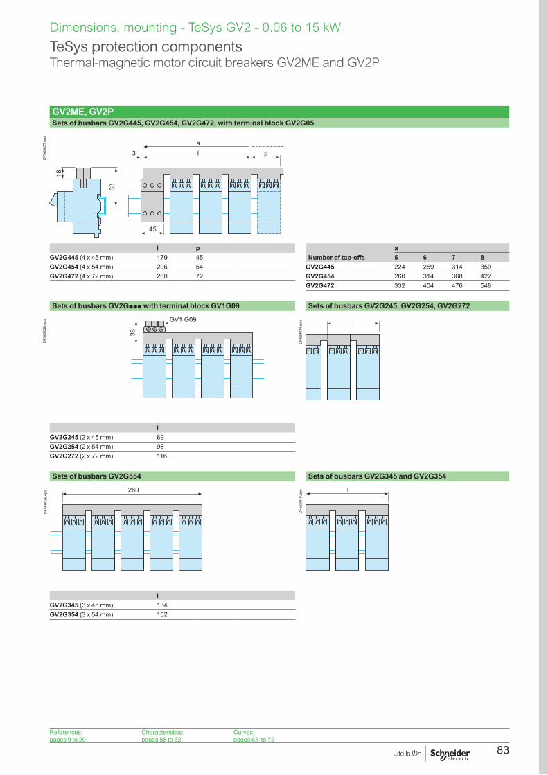
83
GV2ME, GV2PSets of busbars GV2G445, GV2G454, GV2G472, with terminal block GV2G05
63
l3a
18
p
45
DF5
6903
7.ep
s
l p aGV2G445 (4 x 45 mm) 179 45 Number of tap-offs 5 6 7 8GV2G454 (4 x 54 mm) 206 54 GV2G445 224 269 314 359GV2G472 (4 x 72 mm) 260 72 GV2G454 260 314 368 422
GV2G472 332 404 476 548
Sets of busbars GV2Gppp with terminal block GV1G09 Sets of busbars GV2G245, GV2G254, GV2G272
GV1 G09
38
DF5
6902
8.ep
s l
DF5
6903
8.ep
s
lGV2G245 (2 x 45 mm) 89GV2G254 (2 x 54 mm) 98GV2G272 (2 x 72 mm) 116
Sets of busbars GV2G554 Sets of busbars GV2G345 and GV2G354
260
DF5
6903
9.ep
s l
DF5
6904
0.ep
s
lGV2G345 (3 x 45 mm) 134GV2G354 (3 x 54 mm) 152
TeSys protection componentsThermal-magnetic motor circuit breakers GV2ME and GV2P
Dimensions, mounting - TeSys GV2 - 0.06 to 15 kW
References:pages 9 to 20
Characteristics:pages 58 to 62
Curves:pages 63 to 72

84
TeSys protection componentsThermal-magnetic motor circuit breakers GV2RT
Dimensions, mounting - TeSys GV2 - 0.06 to 15 kW
GV2RTDimensions
89
66
X1
44167,5 X1
12,5
45=
=
44,5
DF5
6901
6.ep
s
X1: Electrical clearance = 40 mm for Ue < 690 V
MountingMounting of external operator GV2AP03
1,5...5
13
53 133…282
65
6 = =
12,3
DF5
6901
5.ep
s
On 35 mm 7 rail On panel with adapter plate GV2AF02
On pre-slotted plate AM1 PA
On rails DZ5 MB
c
44,5
44,5
84,5
DF5
6904
1.ep
s
50/6
0
4,2
35
DF5
6901
7.ep
s AF1 EA4
35
50/6
0
DF5
6901
8.ep
s 35
6050
15
DZ5 MB201GV2 AF02DZ5 ME8
DF5
6901
9.ep
s
c = 80 on AM1 DP200 (35 x 7.5)c = 88 on AM1 DE200, ED200 (35 x 15)
References:pages 9 to 20
Characteristics:pages 58 to 62
Curves:pages 63 to 72

85
TeSys protection componentsThermal-magnetic motor circuit breakers GV2L, GV2LE, GV2ME, GV2P, GV2RT
Schemes - TeSys GV2 - 0.06 to 15 kW
SchemesGV2Lpp GV2LEpp GV2Ppp GV2MEpp and GV2RT
2/T1
4/T2
6/T3
1/L1
3/L2
5/L3
DF5
1074
4.ep
s
2/T1
4/T2
6/T3
1/L1
3/L2
5/L3
DF5
3745
8.ep
s
2/T1
4/T2
6/T3
1/L1
3/L2
5/L3
DF5
6906
8.ep
s
2/T1
4/T2
6/T3
1/L1
3/L2
5/L3
DF5
6906
7.ep
s
Front mounting add-on contact blocks Instantaneous auxiliary contacts
Front mounting add-on contact blocks Instantaneous auxiliary contacts and fault signalling contacts
GVAE1 GVAE11 GVAE20 GVAED101 GVAED011
1314 12
11
or
DF5
6906
9.ep
s
1314 22
21
DF5
6907
0.ep
s
1314
2324
DF5
6907
1.ep
s
9798
2324
DF5
6907
2.ep
s
9798
2122
DF5
6907
3.ep
s
Side mounting add-on contact blocks Instantaneous auxiliary contacts and fault signalling contactsGVAD0110 GVAD0101 GVAD1010 GVAD1001
535496
95
DF5
6907
4.ep
s
5251
9695
DF5
6907
5.ep
s
9798
5354
DF5
6907
6.ep
s
9798
5152
DF5
6907
7.ep
s
Instantaneous auxiliary contacts Short-circuit signalling contacts Start-Stop signalling contact blocksGVAN11 GVAN20 GVAM11 GK2AX10 GK2AX20 GK2AX50
(62) 32
(61) 31 43 (73)
44 (74)DF5
6907
8.ep
s
(64) 34
(63) 33 43 (73)
44 (74)D
F569
079.
eps
050608
DF5
6908
0.ep
s 1314
DF5
3747
1.ep
s 1314
2324
DF5
3747
2.ep
s
222113
14
DF5
3747
3.ep
s
Fault signaling contact blocks Voltage trips Current limiterGK2AX12 GK2AX22 GK2AX52 GVAUppp GVASppp GVAXppp GV1L3
9798
DF5
3747
4.ep
s 9798
0708
DF5
3747
5.ep
s 9798 06
05
DF5
3747
6.ep
s
D1
D2
DF5
6908
1.ep
s
D1
D2
DF5
1101
2.ep
s
D1
D2
E1 E2
DF5
6908
3.ep
s
1/L1
3/L2
5/L3
DF5
6908
4.ep
s
Use of fault signalling contact and short-circuit signalling contact
Connection of undervoltage trip for dangerous machines (conforming to INRS) on GV2ME only
GVAD10ppGVAM11
Short-circuit signalling
Trip signalling
N/C or N/O Start-Stop contact
DF5
6908
5.ep
s
2/T1
4/T2
6/T3
1/L1
3/L2
5/L3
D1
D2
E2
E1
10Agl max
DF5
6908
6.ep
s
References:pages 9 to 20
Characteristics:pages 58 to 62
Curves:pages 63 to 72

86

87
TeSys GV35 to 45 kW

88
TeSys protection componentsMotor circuit breakers
Characteristics - TeSys GV3 - 5.5 to 45 kW
EnvironmentCircuit breaker type GV3L GV3P
Conforming to standards IEC/EN 60947-4-1 IEC/EN 60947-2
IEC/EN 60947-4-1 IEC/EN 60947-2UL 60947-4-1CSA C22.2 n° 60947-4-1
Product certifications CCC, EAC, BV, LROS, DNV-GL, ABS
CCC, UL, CSA, EAC, ATEX,BV, LROS, DNV-GL, ABS
Protective treatment "TH" "TC"Degree of protection (front face)
Conforming to IEC 60529
Open mounted Against direct finger contact: IP20In enclosure - GV3 PC01 and
GV3 PC02: IP55Shock resistance Conforming to IEC 60068-2-27 On: 15 gn -11 ms
Off: 30 gn -11 msVibration resistance (1) Conforming to IEC 60068-2-6 4 gn
(5…300 Hz)Ambient air temperature Storage °C -40…+80
Operation Open mounted °C -20…+60 (2)
In enclosure °C – -20…+40Temperature compensation Open mounted °C – -20…+60
In enclosure °C – -20…+40Flame resistance Conforming to IEC 60695-2-1 °C 960Maximum operating altitude m 3000Suitable for isolation Conforming to IEC 60947-1 § 7-1-6 Yes –Resistance to mechanical impact J – 10
IK09 (in enclosure)Sensitivity to phase failure Yes, conforming to IEC 60947-4-1 § 7-2-1-5-2
Technical characteristicsCircuit breaker type GV3L GV3PUtilisation category Conforming to IEC 60947-2 A –
Conforming to IEC 60947-4-1 – AC-3Rated operational voltage(Ue)
Conforming to IEC 60947-2 V 690
Rated insulation voltage (Ui) Conforming to IEC 60947-2 V 690Rated voltage Conforming to UL 60947-4-1,
CSA C 22.2 n° 60947-4-1V 600
Rated operational frequency Conforming to IEC 60947-4-1 UL, CSA
Hz 50/60
Rated impulse withstand voltage (U imp)
Conforming to IEC 60947-2 kV 6
Total power dissipated per pole W 8Mechanical durability (C.O.: Close, Open)
C.O. 50 000
Electrical durability for AC-3 duty
415 V In C.O. 50 000 50 000 (20 000 for GV3P73, GV3P80)
Duty class (maximum operating rate) C.O./h 25Maximum conventional rated thermal current (Ith)
Conforming to IEC 60947-4-1 A – 13 to 80
Rated duty Conforming to IEC 60947-4-1
Continuous duty
Operating threshold of magnetic trips 14 l max
(1) In case of vibration above 3 gn on contactor with electronic coil (TeSys D Green) and direct mounting with LRD relay, it is recommended to mount the devices separately by screws on metal plate.
(2) Leave a space of 9 mm between 2 circuit breakers: either an empty space, or side mounting add-on contact blocks. Side by side mounting is possible up to 40 °C.
References:pages 21 to 26
Curves:pages 92 to 97
Dimensions:pages 101 to 102
Schemes:pages 103
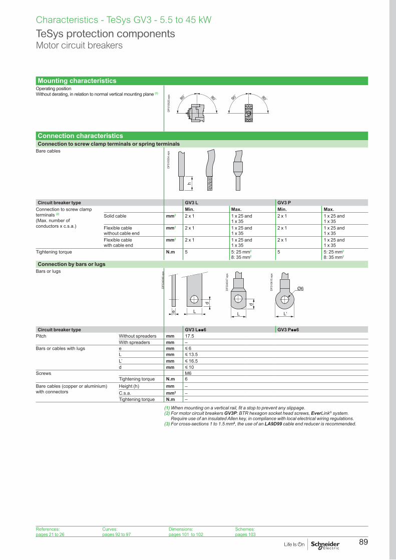
89
TeSys protection componentsMotor circuit breakers
Mounting characteristicsOperating position Without derating, in relation to normal vertical mounting plane (1)
90˚ 90˚90
˚ 90˚
DF5
1052
0.ep
s
Connection characteristicsConnection to screw clamp terminals or spring terminals
Bare cables
h
DF5
1055
4.ep
s
Circuit breaker type GV3 L GV3 PConnection to screw clamp terminals (2) (Max. number of conductors x c.s.a.)
Min. Max. Min. Max.Solid cable mm2 2 x 1 1 x 25 and
1 x 352 x 1 1 x 25 and
1 x 35Flexible cable without cable end
mm2 2 x 1 1 x 25 and 1 x 35
2 x 1 1 x 25 and 1 x 35
Flexible cable with cable end
mm2 2 x 1 1 x 25 and 1 x 35
2 x 1 1 x 25 and 1 x 35
Tightening torque N.m 5 5: 25 mm2
8: 35 mm25 5: 25 mm2
8: 35 mm2
Connection by bars or lugsBars or lugs
e
d
L
DF5
3404
6.ep
s
d
L
DF5
3404
7.ep
s
L'
Ø6DF5
1061
5.ep
s
Circuit breaker type GV3 Lpp6 GV3 Ppp6Pitch Without spreaders mm 17.5
With spreaders mm –Bars or cables with lugs e mm y 6
L mm y 13.5L’ mm y 16.5d mm y 10
Screws M6Tightening torque N.m 6
Bare cables (copper or aluminium) with connectors
Height (h) mm –C.s.a. mm2 –Tightening torque N.m –
(1) When mounting on a vertical rail, fit a stop to prevent any slippage.(2) For motor circuit breakers GV3P: BTR hexagon socket head screws, EverLink® system.
Require use of an insulated Allen key, in compliance with local electrical wiring regulations.(3) For cross-sections 1 to 1.5 mm2, the use of an LA9D99 cable end reducer is recommended.
Characteristics - TeSys GV3 - 5.5 to 45 kW
References:pages 21 to 26
Curves:pages 92 to 97
Dimensions:pages 101 to 102
Schemes:pages 103

90
Characteristics - TeSys GV3 - 5.5 to 45 kW
Breaking capacity of GV3LType GV3L25 GV3L32 GV3L40 GV3L50 GV3L65 GV3L73 GV3L80
Breaking capacity of the circuit-breaker only or of the circuit-breaker combined with a thermal overload relay
230/240 V Icu kA 100 100 100 100 100 100 100
Ics % (1) 100 100 100 100 100 100 100
400/415 V Icu kA 100 100 50 50 50 50 50
Ics % (1) 100 100 100 100 100 60 60
440 V Icu kA 50 50 50 50 50 50 50
Ics % (1) 100 100 100 100 100 60 60
500 V Icu kA 12 12 12 12 12 12 12
Ics % (1) 50 50 50 50 50 50 50
690 V Icu kA 6 6 6 6 6 6 6
Ics % (1) 50 50 50 50 50 50 50
Associated fuses (if required) for use with circuit breaker only or circuit breaker combined with a thermal overload relay if lsc > breaking capacity
230/240 V aM A g g g g g g g
gG A g g g g g g g
415 V aM A g g g g 125 125 125
gG A g g g g 160 160 160
440 V aM A 63 80 125 125 125 125 125
gG A 80 100 160 160 160 160 160
500 V aM A 63 63 63 63 80 80 80
gG A 80 80 80 80 100 100 100
690 V aM A 50 50 50 50 63 63 63
gG A 63 63 63 63 80 80 80
Use of circuit breakers without fuses Minimum cable length (in metres) limiting the maximum short-circuit current to 35 kA maximum.
Cable c.s.a. mm2 y 25 35 50 70 95 - (2) - (2)
Isc (rms) 3-phase, incoming (Ue = 415 V)
50 kA m 5 6 8 10 13 - (2) - (2)
45 kA m 5 5 7 8 10 - (2) - (2)
40 kA m 5 5 5 5 8 - (2) - (2)
37 kA m 5 5 5 5 5 - (2) - (2)
g Fuse not required: breaking capacity Icn > Isc.(1) As % of Icu.(2) Please consult your Regional Sales Office.
TeSys protection componentsMotor circuit breakers GV3L
References:pages 21 to 26
Curves:pages 92 to 97
Dimensions:pages 101 to 102
Schemes:pages 103

91
TeSys protection componentsMotor circuit breakers GV3P
Characteristics - TeSys GV3 - 5.5 to 45 kW
Breaking capacity of GV3PMotor circuit breaker type GV3P
13 18 25 32 40 50 65 73 80Rating A 13 18 25 32 40 50 65 73 80
Breaking capacity conforming to IEC 60947-2
230/240 V Icu kA 100 100 100 100 100 100 100 100 100
Ics % (1) 100 100 100 100 100 100 100 100 100
400/415 V Icu kA 100 100 100 100 50 50 50 50 50
Ics % (1) 100 100 100 100 100 100 100 60 60
440 V Icu kA 50 50 50 50 50 50 50 50 50
Ics % (1) 100 100 100 100 100 100 100 60 60
500 V Icu kA 12 12 12 12 12 12 12 12 12
Ics % (1) 50 50 50 50 50 50 50 50 50
690 V Icu kA 6 6 6 6 6 6 6 6 6
Ics % (1) 50 50 50 50 50 50 50 50 50
Associated fuses, if required if lsc > breaking capacity Icu
230/240 V aM A g g g g g g g g g
gG A g g g g g g g g g
415 V aM A g g g g 125 125 125 125 125
gG A g g g g 160 160 160 160 160
440 V aM A 63 80 125 125 125 125 125 125 125
gG A 80 100 160 160 160 160 160 160 160
500 V aM A 63 63 63 63 80 80 80 80 80
gG A 80 80 80 80 100 100 100 100 100
690 V aM A 50 50 50 50 63 63 63 63 63
gG A 63 63 63 63 80 80 80 80 80
g Fuse not required: breaking capacity Icn > Isc.(1) As % of Icu.
References:pages 21 to 26
Curves:pages 92 to 97
Dimensions:pages 101 to 102
Schemes:pages 103

92
Curves - TeSys GV3 - 5.5 to 45 kW
Tripping curves for GV3L combined with thermal overload relay LRD33Average operating time at 20 °C without prior current flow
10
10 000
1
0,1
0,0011 10 100
1000
100
0,01
321
B
A
Time (s)
x the setting current (Ir)
DB4
2593
3.ep
s
1 3 poles from cold state2 2 poles from cold state3 3 poles from hot state
A Thermal overload relay protection zoneB GV3L protection zone
TeSys protection componentsMagnetic motor circuit breakers GV3L
References:pages 21 to 26
Characteristics:pages 88 to 91
Dimensions:pages 101 to 102
Schemes:pages 103

93
Current limitation on short-circuit for GV3L (3-phase 400/415 V)Dynamic stress
I peak = f (prospective Isc) at 1.05 Ue = 435 V
11 10 100
10
50
1
432
65
Limited peak current (kA)
Prospective Isc (kA)
DB4
1828
0.ep
s
1 Maximum peak current2 GV3L80 - GV3L73 - GV3L653 GV3L504 GV3L405 GV3L326 GV3L25
TeSys protection componentsMagnetic motor circuit breakers GV3L
Curves - TeSys GV3 - 5.5 to 45 kW
References:pages 21 to 26
Characteristics:pages 88 to 91
Dimensions:pages 101 to 102
Schemes:pages 103

94
Curves - TeSys GV3 - 5.5 to 45 kW
Thermal limit on short-circuit for GV3LThermal limit in A2s
Sum of I2dt = f (prospective Isc) at 1.05 Ue = 435 V
10
11 10 100
100
1000
321
456
Sum of I2dt (A2s)
Prospective Isc (kA)
DB4
2593
6.ep
s
1 GV3L73 - GV3L802 GV3L653 GV3L504 GV3L405 GV3L326 GV3L25
TeSys protection componentsMagnetic motor circuit breakers GV3L
References:pages 21 to 26
Characteristics:pages 88 to 91
Dimensions:pages 101 to 102
Schemes:pages 103

95
Thermal-magnetic tripping curvesAverage operating times at 20 °C related to multiples of the setting current
0,001
0,1
1
10
100
0,01
1 10 100
1000
10 000
1a1b
2a
2b
Time (s)
x the setting current (Ir)
DB4
2586
3.ep
s
1a 3 poles from cold state (Ir mini.): GV3P1b 3 poles from cold state (Ir maxi.): GV3P2a 3 poles from hot state (Ir mini.): GV3P2b 3 poles from hot state (Ir maxi.): GV3P
TeSys protection componentsThermal-magnetic motor circuit breakers GV3P
Curves - TeSys GV3 - 5.5 to 45 kW
References:pages 21 to 26
Characteristics:pages 88 to 91
Dimensions:pages 101 to 102
Schemes:pages 103
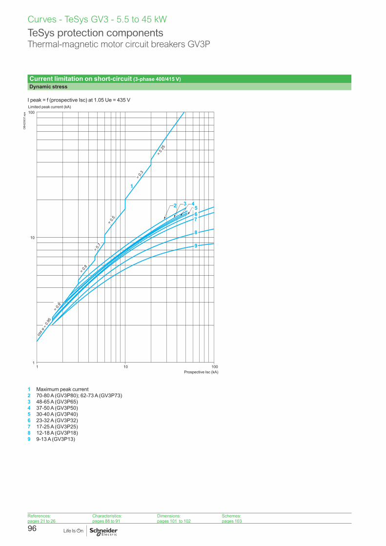
96
Curves - TeSys GV3 - 5.5 to 45 kW
Current limitation on short-circuit (3-phase 400/415 V)Dynamic stress
I peak = f (prospective Isc) at 1.05 Ue = 435 V
1 10 100
100
10
1
76
8
9
= 0.9
= 0.8
= 0.
7
= 0.5
= 0.3
= 0.
25
5
1
3 42
Limited peak current (kA)
Prospective Isc (kA)
DB4
2593
7.ep
s
1 Maximum peak current2 70-80 A (GV3P80); 62-73 A (GV3P73)3 48-65 A (GV3P65)4 37-50 A (GV3P50)5 30-40 A (GV3P40)6 23-32 A (GV3P32)7 17-25 A (GV3P25)8 12-18 A (GV3P18)9 9-13 A (GV3P13)
TeSys protection componentsThermal-magnetic motor circuit breakers GV3P
References:pages 21 to 26
Characteristics:pages 88 to 91
Dimensions:pages 101 to 102
Schemes:pages 103

97
Maximum thermal limit on short-circuitThermal limit in kA2s in the magnetic operating zone
Sum of I2dt = f (prospective Isc) at 1.05 Ue = 435 V
100
1000
10
11 10 100
4321
8
7
65
Sum of I2dt (kA2s)
Prospective Isc (kA)
DB4
2593
8.ep
s
1 70-80 (GV3P80) - 62-73 (GV3P73)2 48-65 A (GV3P65)3 37-50 A (GV3P50)4 30-40 A (GV3P40)5 23-32 A (GV3P32)6 17-25 A (GV3P25)7 12-18 A (GV3P18)8 9-13 A (GV3P13)
TeSys protection componentsThermal-magnetic motor circuit breakers GV3P
Curves - TeSys GV3 - 5.5 to 45 kW
References:pages 21 to 26
Characteristics:pages 88 to 91
Dimensions:pages 101 to 102
Schemes:pages 103

98
Characteristics of GV3 electric tripsType of trip GVAUppp
MN undervoltage tripGVASppp MX shunt trip
Rated insulation voltage (Ui) Conforming to IEC 60947-1
V 690 690
Conforming to CSA C22-2 n°14, UL 508
V 600 600
Operational voltage (Ue) Conforming to IEC 60947-1
V 0.85...1.1 Uc 0.7...1.1 Uc
Drop-out voltage V 0.7...0.35 Uc 0.75...0.2 Uc
Inrush consumption a c
VA 12 14
Sealed consumption a c
VA 3.5 5
Operating time Conforming to IEC 60947-1 ms
From the moment the voltage reaches its operational value until opening of the circuit breaker. 10...15
On-load factor 100 %
Cabling (spring connection)
Number of conductors 2 or 4
Solid cable mm2 1...2.5
Flexible cable without cable end
mm2
AWG0.75...2.5
Flexible cable with cable end
mm2 0.75...2.5
Tightening torque N.m 1.4 max
Mechanical durability (C.O.: Close - Open)
C.O. 10000 (GV3 P and GV3 L)
TeSys protection componentsGV3 motor circuit breakersElectric trips
Curves - TeSys GV3 - 5.5 to 45 kW

99
Characteristics - TeSys GV3 - 5.5 to 45 Kw
Type of contacts Instantaneous auxiliary GVAN, GVAD
Fault signalling GVAD, GVAM11 (1)
Instantaneous auxiliary GVAE
Rated insulation voltage (Ui) (associated insulation coordination)
Conforming to IEC 60947-1 V 690 690 250 (690 in relation to main circuit)
Conforming to CSA C22-2 n° 14 and UL 508
V 600 300 300
Conventional thermal current (Ith)
Conforming to IEC 60947-5-1 A 6 2.5 2.5
Conforming to CSA C22-2 n° 14 and UL 508
A 5 1 1
Mechanical durability (C.O.: Close - Open)
C.O. 100 000 1000 100 000
Operational power and current conforming to IEC 60947-5-1. a.c. operation
AC-15/100 000 C.O. AC-14/1000 C.O. AC-15/100 000 C.O.
Rated operational voltage (Ue)
V 48 110 127
230 240
380 415
440 500 690 24 48 110 127
230 240
24 48 110 127
230 240
Operation Operational power, normal conditions
VA 300 500 720 850 650 500 400 36 48 72 72 48 60 120 120
Occasional breaking and making capacities, abnormal conditions
kVA 3 7 13 15 13 12 9 0.22 0.3 0.45 0.45 0.48 0.6 1.27 2.4
Rated operational current (Ie)
A 6 4.5 3.3 2.2 1.5 1 0.6 1.5 1 0.5 0.3 2 1.25 1 0.5
Operational power and current conforming to IEC 60947-5-1. d.c.
DC-13/100 000 C.O. DC-13/1000 C.O. DC-13/100 000 C.O.
Rated operational voltage (Ue)
V 24 48 60 110 240(2)
– – 24 48 60 – 24 48 60 –
Operation Operational power, normal conditions
W 140 240 180 140 120 – – 24 15 9 – 24 15 9 –
Occasional breaking and making capacities, abnormal conditions
W 240 360 240 210 180 – – 100 50 50 – 100 50 50 –
Rated operational current (Ie)
A 6 5 3 1.3 0.5 – – 1 0.3 0.15 – 1 0.3 0.15 –
Low power switching reliability of contact GVAE: Number of failures for “n” million operating cycles (17 V-5 mA): = 10-6
Minimum operational conditions d.c. operation
V 17mA 5
Short-circuit protection By GB2CBpp circuit breaker (rating according to operational current for Ue y 415 V) or by gG fuse 10 A max
GB2CB06 or gG fuse 10 A max
Cabling, screw clamp terminals Number of conductors 1 2Solid cable mm2 1…2.5 1…2.5Flexible cable without cable end mm2 0.75…2.5 0.75…2.5Flexible cable with cable end mm2 0.75…1.5 0.75…1.5Tightening torque N.m 1.4 max 1.4 max
Cabling, spring terminal connections
GVAN onlyFlexible cable without cable end mm2 0.75…2.5 0.75…2.5 – 0.75…1.5
Operation of instantaneous auxiliary contactsGV3P, GV3L
0 1Power pole
GV AN20 FF
GV AN11 FO
GV AE1 FO
GV AE20 FF
GV AE11 FO
GV AD10pp FO
GV AED101 FGV AED011 O
GV20 1
Power pole
GV AN20 FF
GV AN11 FO
GV AE1 FO
GV AE20 FF
GV AE11 FO
GV AD10pp FGV AD11pp O
Contact open Contact Close
DB4
0239
9.ep
s
Operation of fault signalling contacts
GVAM11Change of state following tripping on short-circuit.
GVAD10pp and GVAD01ppChange of state following tripping on short-circuit, overload or undervoltage.
(1) For application example of fault signalling contact and short-circuit signalling contact, see page 114.(2) Add an RC circuit type LA4 D to the load terminals, see page 114.
TeSys protection componentsMotor circuit breakers GV3P, GV3LAuxiliary contacts
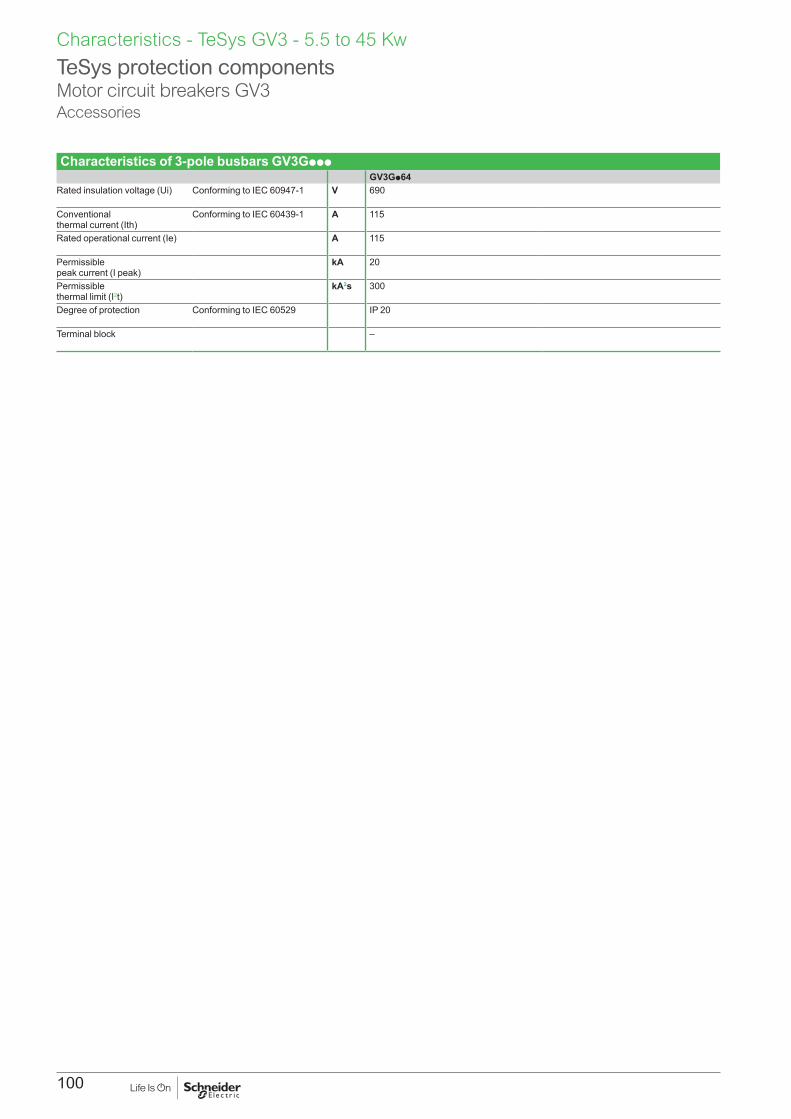
100
Characteristics - TeSys GV3 - 5.5 to 45 Kw
Characteristics of 3-pole busbars GV3GpppGV3Gp64
Rated insulation voltage (Ui) Conforming to IEC 60947-1 V 690
Conventional thermal current (Ith)
Conforming to IEC 60439-1 A 115
Rated operational current (Ie) A 115
Permissible peak current (I peak)
kA 20
Permissible thermal limit (I2t)
kA2s 300
Degree of protection Conforming to IEC 60529 IP 20
Terminal block –
TeSys protection componentsMotor circuit breakers GV3Accessories

101
Dimensions, mounting - TeSys GV3 - 5.5 to 45 kW
GV3L, GV3PDimensions
136
X1
X1
132
6864
55
DF5
3748
0.ep
s
9 18
(2)(1)
DF5
3748
1.ep
s
X1 = Electrical clearance (ISC max) 40 mm for Ue y 500 V, 50 mm for Ue y 690 V
(1) Blocks GVANpp , GVADpp and GVAM11.(2) Blocks GV3AUpp and GV3ASpp.
Note: Leave a space of 9 mm between 2 circuit breakers: either an empty space or side-mounting add-on contact blocks. Side by side mounting is possible up to 40 °C.
MountingMounting with Tesys contactor LC1D40A…D80A and relay LR3D313…380 (1) (2) (3)
Side by side mounting with Tesys contactor LC1D40A…D80A(S-shape busbar system GV3S (1))
185
299
7011
5
136 55
DF5
6774
4.ep
s
136 11919
5
DF5
6774
5.ep
s
(1) Mountings with c.b. up to GV3L73, GV3P73.(2) For GV3L80, GV3P80 use cable between components for dissipating heat. Consult online datasheets for values(3) S-shape busbar system suitable up to 73 A.
Mounting on rail AM1 DE200 or AM1 ED201 Panel mounting, using M4 screws
144
6864
DF5
3748
2.ep
s
136 3xØ4
137,
5
37,5
DF5
6774
8.ep
s
Mounting on pre-slotted plate AM1 PA Set of busbars GV3G264 Set of busbars GV3G364
136 18,7 18,7
137,
5
AF1 EA4
DF5
3743
5.ep
s 119
16
DF5
1063
7.ep
s 183
16
DF5
1063
8.ep
s
TeSys protection componentsMotor circuit breakers GV3L, GV3 P
References:pages 21 to 26
Characteristics:pages 88 to 91
Curves:pages 92 to 97
Schemes:pages 103

102
MountingMounting of external operator GV3APN01, GV3APN02 or GV3APN04 for motor circuit breakers GV3L
0,5...443
60
a
60
6
= =
DB1
2741
6.ep
s
Door cut-out
48= =
==
48
4Ø3,5 (1)16
16
Ø3,5
Ø22
DB1
2663
4.ep
s
Mounting of external operator GVAPH03 for motor circuit breakers GV3L
0,5...4
43 b
60
6
213,
4
73,8
= =
DB1
2741
7.ep
s
Door cut-out
48= =
==
48
4Ø3,5 (1)16
16
Ø3,5
Ø22D
B126
634.
eps
a bMini Maxi Mini Maxi
GV3APNpp 189 300 - -GV3APNpp + GVAPK12 300 481GV3APNpp + GVAPH03 - - 200 300GV3APNpp + GVAPH03 + GVAPK12
- - 300 492
(1) For IP65 only.
(1) For IP65 only.
Dimensions, mounting - TeSys GV3 - 5.5 to 45 kW
TeSys protection componentsMagnetic motor circuit breakers GV3L, GV3P
References:pages 21 to 26
Characteristics:pages 88 to 91
Curves:pages 92 to 97
Schemes:pages 103
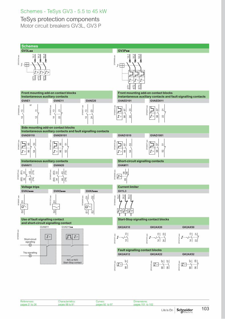
103
Schemes - TeSys GV3 - 5.5 to 45 kW
TeSys protection componentsMotor circuit breakers GV3L, GV3 P
SchemesGV3Lpp GV3Ppp
2/T1
4/T2
6/T3
1/L1
3/L2
5/L3
DF5
1074
4.ep
s
2/T1
4/T2
6/T3
1/L1
3/L2
5/L3
DF5
6906
8.ep
s
Front mounting add-on contact blocks Instantaneous auxiliary contacts
Front mounting add-on contact blocks Instantaneous auxiliary contacts and fault signalling contacts
GVAE1 GVAE11 GVAE20 GVAED101 GVAED011
1314 12
11
or
DF5
6906
9.ep
s
1314 22
21
DF5
6907
0.ep
s
1314
2324
DF5
6907
1.ep
s
9798
2324
DF5
6907
2.ep
s
9798
2122
DF5
6907
3.ep
s
Side mounting add-on contact blocks Instantaneous auxiliary contacts and fault signalling contactsGVAD0110 GVAD0101 GVAD1010 GVAD1001
535496
95
DF5
6907
4.ep
s
5251
9695
DF5
6907
5.ep
s
9798
5354
DF5
6907
6.ep
s
9798
5152
DF5
6907
7.ep
s
Instantaneous auxiliary contacts Short-circuit signalling contactsGVAN11 GVAN20 GVAM11
(62) 32
(61) 31 43 (73)
44 (74)DF5
6907
8.ep
s
(64) 34
(63) 33 43 (73)
44 (74)D
F569
079.
eps
050608
DF5
6908
0.ep
s
Voltage trips Current limiterGVAUppp GVASppp GVAXppp GV1L3
D1
D2
DF5
6908
1.ep
s
D1
D2
DF5
1101
2.ep
s
D1
D2
E1 E2
DF5
6908
3.ep
s
1/L1
3/L2
5/L3
DF5
6908
4.ep
s
Use of fault signalling contact and short-circuit signalling contact
Start-Stop signalling contact blocks
GVAD10ppGVAM11
Short-circuit signalling
Trip signalling
N/C or N/O Start-Stop contact
DF5
6908
5.ep
s
GK2AX10 GK2AX20 GK2AX50
1314
DF5
3747
1.ep
s 1314
2324
DF5
3747
2.ep
s
222113
14
DF5
3747
3.ep
s
Fault signalling contact blocksGK2AX12 GK2AX22 GK2AX52
9798
DF5
3747
4.ep
s 9798
0708
DF5
3747
5.ep
s 9798 06
05
DF5
3747
6.ep
s
References:pages 21 to 26
Characteristics:pages 88 to 91
Curves:pages 92 to 97
Dimensions:pages 101 to 102

104

105
TeSys GV40.25 to 55 kW
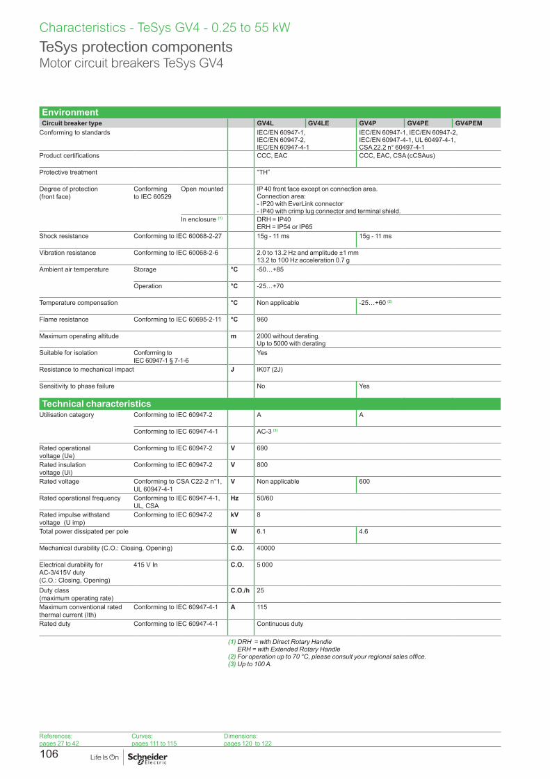
106
EnvironmentCircuit breaker type GV4L GV4LE GV4P GV4PE GV4PEM
Conforming to standards IEC/EN 60947-1, IEC/EN 60947-2,IEC/EN 60947-4-1
IEC/EN 60947-1, IEC/EN 60947-2, IEC/EN 60947-4-1, UL 60497-4-1, CSA 22.2 n° 60497-4-1
Product certifications CCC, EAC CCC, EAC, CSA (cCSAus)
Protective treatment “TH”
Degree of protection (front face)
Conforming to IEC 60529
Open mounted IP 40 front face except on connection area.Connection area:- IP20 with EverLink connector- IP40 with crimp lug connector and terminal shield.
In enclosure (1) DRH = IP40 ERH = IP54 or IP65
Shock resistance Conforming to IEC 60068-2-27 15g - 11 ms 15g - 11 ms
Vibration resistance Conforming to IEC 60068-2-6 2.0 to 13.2 Hz and amplitude ±1 mm 13.2 to 100 Hz acceleration 0.7 g
Ambient air temperature Storage °C -50…+85
Operation °C -25…+70
Temperature compensation °C Non applicable -25…+60 (2)
Flame resistance Conforming to IEC 60695-2-11 °C 960
Maximum operating altitude m 2000 without derating. Up to 5000 with derating
Suitable for isolation Conforming to IEC 60947-1 § 7-1-6
Yes
Resistance to mechanical impact J IK07 (2J)
Sensitivity to phase failure No Yes
Technical characteristicsUtilisation category Conforming to IEC 60947-2 A A
Conforming to IEC 60947-4-1 AC-3 (3)
Rated operational voltage (Ue)
Conforming to IEC 60947-2 V 690
Rated insulation voltage (Ui)
Conforming to IEC 60947-2 V 800
Rated voltage Conforming to CSA C22-2 n°1, UL 60947-4-1
V Non applicable 600
Rated operational frequency Conforming to IEC 60947-4-1, UL, CSA
Hz 50/60
Rated impulse withstand voltage (U imp)
Conforming to IEC 60947-2 kV 8
Total power dissipated per pole W 6.1 4.6
Mechanical durability (C.O.: Closing, Opening) C.O. 40000
Electrical durability for AC-3/415V duty (C.O.: Closing, Opening)
415 V In C.O. 5 000
Duty class (maximum operating rate)
C.O./h 25
Maximum conventional rated thermal current (Ith)
Conforming to IEC 60947-4-1 A 115
Rated duty Conforming to IEC 60947-4-1 Continuous duty
(1) DRH = with Direct Rotary Handle ERH = with Extended Rotary Handle
(2) For operation up to 70 °C, please consult your regional sales office.(3) Up to 100 A.
TeSys protection componentsMotor circuit breakers TeSys GV4
Characteristics - TeSys GV4 - 0.25 to 55 kW
References:pages 27 to 42
Curves:pages 111 to 115
Dimensions:pages 120 to 122

107
TeSys protection componentsMotor circuit breakers TeSys GV4
Characteristics - TeSys GV4 - 0.25 to 55 kW
Mounting characteristicsOperating position Without derating, in relation to normal vertical mounting plane (1)
90° 90°90
° 90°
90°90° 90°90°
DB4
2528
3.ep
s
Power connection characteristicsPower connection by bare cables (EverLink connector)
Bare cables
h
DF5
1055
4.ep
s
Connection to screw clamp terminals (Max. number of conductors x c.s.a.)
Min. Max.Solid cable mm2
AWGCu 1 x 1.5 + 1 x 2.5 Cu 2 x 14
Cu 1 x 70 + 1 x 95 Cu 1 x 2/0 + 1 x 3/0
Flexible cable without cable end
mm2
AWGCu 1 x 1.5 + 1 x 2.5 Cu 2 x 6
Cu 1 x 50 + 1 x 70 Cu 1 x 1/0 + 1 x 2/0
Flexible cable with cable end
mm2
AWGCu 1 x 1.5 + 1 x 2.5 Cu 2 x 6
Cu 1 x 50 + 1 x 70Cu 1 x 1/0 + 1 x 2/0
Tightening torque N.m 5 y 10 mm2 / 8 AWG 9 u 16 mm2 / 6 AWG
Stripping length (h) Solid cable mm 20
Power connection by bars or lugsBars or lugs
e
d
L
DF5
3404
6.ep
s
d
L
DF5
3404
7R.e
ps
D
L
DB4
2527
8.ep
s
Pitch Without spreaders mm 27
With spreaders mm 35
Bars or cables with lugs e mm y 8
L mm y 20
d mm y 7
D mm 6.4
M6 Screws Tightening torque N.m 5 y 10 mm2 / 8 AWG 9 u 16 mm2 / 6 AWG
(1) When mounting on a vertical rail, fit a stop to prevent any slippage.
References:pages 27 to 42
Curves:pages 111 to 115
Dimensions:pages 120 to 122

108
Breaking capacity of GV4L and GV4LECircuit breaker type GV4LpppB
GV4LEpppBGV4LpppN GV4LEpppN
GV4LEpppS
Rating A 25 50 80 115 2 3.5 7 12.5 25 50 80 115 2 3.5 7 12.5 25 50 80 115
Breaking capacity conforming to IEC 60947-2
230/240 V Icu kA 50 100 120
Ics % (1) 100 100 100
400/415 V Icu kA 25 50 100
Ics % (1) 100 100 100
440 V Icu kA 20 50 70
Ics % (1) 100 100 100
500 V Icu kA 10 25 30
Ics % (1) 100 100 100
525 V Icu kA - 15 18
Ics % (1) - 100 100
690 V Icu kA - 8 10
Ics % (1) - 25 25
(1) As % of Icu.
TeSys protection componentsMagnetic motor circuit breakers GV4L and GV4LE
Characteristics - TeSys GV4 - 0.25 to 55 kW
References:pages 27 to 42
Curves:pages 111 to 115
Dimensions:pages 120 to 122

109
Breaking capacity of GV4P, GV4PE and GV4PEMCircuit breaker type GV4PpppB
GV4PEpppB GV4PEMpppB
GV4PpppN GV4PEpppN GV4PEMpppN
GV4PEpppS GV4PEMpppS
Rating A 25 50 80 115 2 3.5 7 12.5 25 50 80 115 2 3.5 7 12.5 25 50 80 115
Breaking capacity conforming to IEC 60947-2
230/240 V Icu kA 50 100 120
Ics % (1) 100 100 100
400/415 V Icu kA 25 50 100
Ics % (1) 100 100 100
440 V Icu kA 20 50 70
Ics % (1) 100 100 100
500 V Icu kA 10 25 30
Ics % (1) 100 100 100
525 V Icu kA - 15 18
Ics % (1) - 100 100
690 V Icu kA - 8 10
Ics % (1) - 25 25
Breaking capacity conforming to UL 60947-4-1 and CSA 22.2 n° 60947-4-1
120 V kA 35 65 100
208 V kA 35 65 100
240 V kA 35 65 100
480Y / 277 V
kA 18 35 65
480 V (2) kA 18 35 65
600Y / 347 V
kA 14 18 25
600 V (2) kA 14 18 25
(1) As % of Icu.(2) Except for MCC suitable for TAP conductor protection, in motor group installation.
TeSys protection componentsThermal-magnetic motor circuit breakers GV4P, GV4PE and GV4PEM
Characteristics - TeSys GV4 - 0.25 to 55 kW
References:pages 27 to 42
Curves:pages 111 to 115
Dimensions:pages 120 to 122

110
Curves - TeSys GV4 - 0.25 to 55 kW
Tripping curves for GV4L and GV4LE combined with thermal overload relay LRD or LR9Average operating times at 20 ° C related to multiples of the setting current
GV4L02 and GV4LE02 to 12 with LRD05 to LRD14, GV4L80 and GV4LE80 with LRD3363
GV4L25 AND GV4LE25 with LRD 318, LRD325 GV4L50 AND GV4LE50 with LRD 332, LRD 340, LRD 350
A1
A
B
23
0
0.01
0.1
1
10
100
10 000
1000
1 10 100
4
Time (s)
x Rating current (Ir)
DB4
2530
6.ep
s
A1
A
B
23
0
0.01
0.1
1
2
4
20
40
10
100
10 000
1000
1 10 100
4
Time (s)
x Rating current (Ir)
DB4
2595
7.ep
s
1 3 poles from cold state2 2 poles from cold state3 3 poles from hot state4 6 ...14 Ir
A Thermal overload relay protection zone
B GV4L protection zone
1 3 poles from cold state2 2 poles from cold state3 3 poles from hot state4 6 ...14 Ir
A Thermal overload relay protection zone
B GV4L protection zone
GV4L115 and GV4LE115 with class 10 LR9F5367, LR9D5369 and class 20 LR9D5567, LR9F5569
0
0.01
0.1
1
10
100
10 000
1000
1 101.12 100
2
3 B
1A
Time (s)
x Rating current (Ir)
DB4
2529
2.ep
s
1 Cold state curve2 Hot state curve3 6 ...14 Ir
TeSys protection componentsMagnetic motor circuit breakers GV4L, GV4LE
References:pages 27 to 43
Characteristics:pages 106 to 118
Dimensions:pages 120 to 122

111
Curves - TeSys GV4 - 0.25 to 55 kW
Current limitation on short-circuit for GV4L, GV4LE (3-phase 400/415 V)Dynamic stress
I peak = f (prospective Isc) at 1.05 Ue = 435 V
cos
ø =
0.95
= 0.
9
= 0.
8=
0.7
= 0.
5
= 0.
25
= 0.
3
1
23
45
6
7
8
9
0,1
1
10
100
0,1 1 10 100
Limited peak current (kA)
Prospective Isc (kA)
DB4
2530
4.ep
s
1 Maximum peak current2 GV4L1153 GV4L804 GV4L505 GV4L256 GV4L127 GV4L078 GV4L039 GV4L02
TeSys protection componentsMagnetic motor circuit breakers GV4L, GV4LE
References:pages 27 to 43
Characteristics:pages 106 to 118
Dimensions:pages 120 to 122

112
Current limitation on short-circuit for GV4L, GV4LE + thermal overlaoad relay LRD or LR9 (3-phase 400/415 V)Dynamic stress
I peak = f (prospective Isc) at 1.05 Ue = 435 V
cos
ø =
0.95
= 0.
9
= 0.
8=
0.7
= 0.
5
= 0.
25
= 0.
31
0,1
1
10
100
0,1 1 10 100
23
4
5
6
7
8
9
Limited peak current (kA)
Prospective Isc (kA)
DB4
2530
5.ep
s
1 Maximum peak current2 GV4L115 + LR9D5367 or LR9F53673 GV4L80 + LRD33614 GV4L50 + LRD3405 GV4L25 + LRD3256 GV4L12 + LRD3137 GV4L07 + LRD128 GV4L03 + LRD079 GV4L02 + LRD07
TeSys protection componentsMagnetic motor circuit breakers GV4L, GV4LE
Curves - TeSys GV4 - 0.25 to 55 kW
References:pages 27 to 43
Characteristics:pages 106 to 118
Dimensions:pages 120 to 122

113
Thermal limit on short-circuit for GV4L, GV4LEThermal limit in A2s
Sum of I2dt = f (prospective Isc) at 1.05 Ue = 435 V
1
10
100
1000
1 10 100
12
3 4
5
6
7
8
Sum of I2dt (A2s)
Prospective Isc (kA)
DB4
2515
3.ep
s
1 GV4L1152 GV4L803 GV4L504 GV4L255 GV4L126 GV4L077 GV4L038 GV4L02
TeSys protection componentsMagnetic motor circuit breakers GV4L, GV4LE
Curves - TeSys GV4 - 0.25 to 55 kW
References:pages 27 to 43
Characteristics:pages 106 to 118
Dimensions:pages 120 to 122

114
Thermal limit on short-circuit for GV4L, GV4LE + thermal overlaoad relay LRD or LR9Thermal limit in kA in the magnetic operating zone
Sum of I2dt = f (prospective Isc) at 1.05 Ue = 435 V
0,1
1
10
100
1000
1 10 100
123 4
5
6
7
8
Sum of I2dt (A2s)
Prospective Isc (kA)
DB4
2515
4.ep
s
1 GV4L115 + LR9D5367 or LR9F53672 GV4L80 + LRD33613 GV4L50 + LRD3404 GV4L25 + LRD3255 GV4L12 + LRD3136 GV4L07+ LRD127 GV4L03+ LRD078 GV4L02 + LRD07
TeSys protection componentsMagnetic motor circuit breakers GV4L, GV4LE
Curves - TeSys GV4 - 0.25 to 55 kW
References:pages 27 to 43
Characteristics:pages 106 to 118
Dimensions:pages 120 to 122
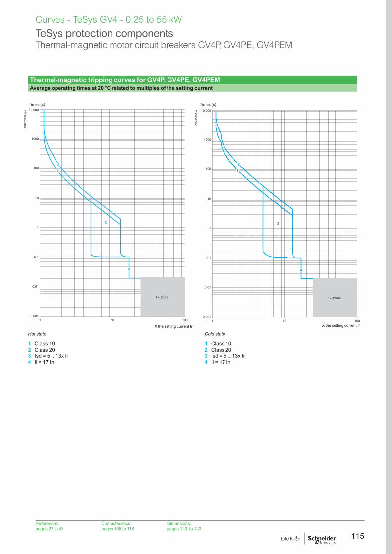
115
TeSys protection componentsThermal-magnetic motor circuit breakers GV4P, GV4PE, GV4PEM
Curves - TeSys GV4 - 0.25 to 55 kW
Thermal-magnetic tripping curves for GV4P, GV4PE, GV4PEMAverage operating times at 20 °C related to multiples of the setting current
0.001
0.01
0.1
1
10
100
10 000
1000
1 10 100
t < 20ms
2
1
3
4
Times (s)
X the setting current Ir
DB4
2593
0.ep
s
0.001
0.01
0.1
1
10
100
10 000
1000
1 10 100
3
t < 20ms
4
2
1
Times (s)
X the setting current Ir
DB4
2595
8.ai
Hot state Cold state
1 Class 102 Class 203 Isd = 5 ...13x Ir4 Ii = 17 In
1 Class 102 Class 203 Isd = 5 ...13x Ir4 Ii = 17 In
References:pages 27 to 43
Characteristics:pages 106 to 118
Dimensions:pages 120 to 122

116
Current limitation on short-circuit for GV4P, GV4PE, GV4PEM (3-phase 400/415 V)Dynamic stress
I peak = f (prospective Isc) at 1.05 Ue = 435 V
0,1
1
10
100
0,1 1
cos
ø =
0.95
10 100
= 0.
9
= 0.
8=
0.7
= 0.
5
= 0.
3
= 0.
25
1
234
56
7
8
9
Limited peak current (kA)
Prospective Isc (kA)
DB4
2515
5.ep
s
1 Maximum peak current2 GV4P1153 GV4P804 GV4P505 GV4P256 GV4P127 GV4P078 GV4P039 GV4P02
TeSys protection componentsThermal-magnetic motor circuit breakers GV4P, GV4PE, GV4PEM
Curves - TeSys GV4 - 0.25 to 55 kW
References:pages 27 to 43
Characteristics:pages 106 to 118
Dimensions:pages 120 to 122

117
Thermal limit on short-circuit for GV4P, GV4PE, GV4PEMThermal limit in kA2s in the magnetic operating zone
Sum of I2dt = f (prospective Isc) at 1.05 Ue = 435 V
1
10
100
1000
1 10 100
12
34 5
6
7
8
Sum of I2dt (A2s)
Prospective Isc (kA)
DB4
2515
6.ep
s
1 GV4P1152 GV4P803 GV4P504 GV4P255 GV4P126 GV4P077 GV4P038 GV4P02
TeSys protection componentsThermal-magnetic motor circuit breakers GV4P, GV4PE, GV4PEM
Curves - TeSys GV4 - 0.25 to 55 kW
References:pages 27 to 43
Characteristics:pages 106 to 118
Dimensions:pages 120 to 122

118
Characteristics of electric tripsType of trip GV4AUppp MN (undervoltage release)
Rated insulation voltage (Ui)
Conforming to IEC 60947-1
V = Ue
Operational voltage (Ue)
Conforming to IEC 60947-1
V 24 V AC/DC
48 V AC/DC
110-130 V AC 125 V DC
208-240 V 60 Hz 220-240 V 50 Hz
277 V 60 Hz
380-415 V 60 Hz 440-480 V 60 Hz
Inrush consumption a c
VA < 7 VA < 2 W
< 7 VA < 2 W
< 7 VA < 2 W
< 7 VA < 7 VA < 7 VA < 7 VA
Sealed consumption a c
VA < 7 VA < 2 W
< 7 VA < 2 W
< 7 VA < 2 W
< 7 VA < 7 VA < 7 VA < 7 VA
Operating time Conforming to IEC 60947-1
ms < 50
On-load factor 100 %
Cabling (spring connection)
Number of conductors 1 per terminal
Solid cable mm2 No solid cable allowed
Flexible cable without cable end
mm2
AWGCu 0.5 mm2 to 1.5 mm2
Cu 20AWG to 16AWG Flexible cable with cable end
mm2 No cable with cable end allowed
Tightening torque N.m NA
Mechanical durability (C.O.: Close - Open)
C.O. 20000
Characteristics of electric tripsType of trip GV4ASppp MX (Shunt trip)
Rated insulation voltage (Ui)
Conforming to IEC 60947-1
V = Ue
Operational voltage (Ue)
Conforming to IEC 60947-1
V 24 V AC/DC
48 V AC/DC
110-130 V AC 125 V DC
208-240 V 60 Hz 220-240 V 50 Hz
380-415 V 50 Hz 440-480 V 60 Hz
Inrush consumption a c
VA < 6 VA < 10 W
< 6 VA < 10 W
< 6 VA < 10 W
< 6 VA < 6 VA
Sealed consumption a c
VA < 4 VA < 1 W
< 4 VA < 1 W
< 4 VA < 1 W
< 4 VA < 4 VA
Operating time Conforming to IEC 60947-1
ms < 50
On-load factor 100 %
Cabling (spring connection)
Number of conductors 1 per terminal
Solid cable mm2 No solid cable allowed
Flexible cable without cable end
mm2
AWGCu 0.5 mm2 to 1.5 mm2
Cu 20AWG to 16AWG Flexible cable with cable end
mm2 No cable with cable end allowed
Tightening torque N.m NA
Mechanical durability (C.O.: Close - Open)
C.O. 20000
TeSys protection componentsThermal-magnetic motor circuit breakersVoltage releases
Characteristics - TeSys GV4 - 0.25 to 55 kW
References:pages 27 to 42
Characteristics:pages 106 to 118
Curves:pages 111 to 115

119
Characteristics - TeSys GV
Auxiliary contact characteristicsType of contacts Auxiliary contact block
GV4AE11SDx contact module for GV4PEM GV4ADM1111
Rated insulation voltage(Ui) Conforming to IEC 60947-1 V 690 250
Conforming to CSA C22-2 n°14 UL 508
V - -
Conventional thermal current (Ith)
Conforming to IEC 60947-5-1 A 5 5
Conforming to CSA C22-2 n°14 UL 508
A 5 5
Mechanical durability (C.O.: Close - Open)
C.O. 40 000 100 000
Operational power and current conforming to IEC 60947-5-1 a.c. operation
Rated operational voltage (Ue)
V 24 48 110/ 127
230/ 240
380/ 440
660/ 690
48 110 230/ 240
380/ 415
440 690
Operational power (AC12)
VA 120 240 635 1200 2200 3450 400
Occasional breaking and making capacities
kVA 1.2 2.4 6.35 12 22 34.5
Operational current (Ie)
AC-12 A 5 5 5 5 5 5
AC-15 A 5 5 4 3 2.5 0.1 3 1.5
Operational power and current conforming to IEC 60947-5-1 d.c. operation
Rated operational voltage (Ue)
V 24 48 110 250 24 48 60 110 250
Operational power (DC12)
W 120 120 66 75 50
Occasional breaking and making capacities
W 1200 1200 660 750
Rated operational current (Ie)
DC-12 A 5 2.5 0.6 0.3
DC-13 A 2.5 1.2 0.35 0.05 2 0.22 0.11
DC-14 A 1 0.2 0.05 0.03
Low power switching reliability of contact 10-6 at 17 V / 2 mA
Minimum operational conditionsd.c. operation
V 17
mA 2
Short-circuit protection 5 A fuse gG conforming to IEC 60947-5-1
Spring terminals cabling Number of conductors 1 per hole
Solid cable mm2 - 0.2 to 1.5
Flexible cable without cable end mm2 0.5 to 1.5 0.2 to 2.5
Flexible cable with cable end mm2 - 0.25 to 1.5
TeSys protection componentsThermal-magnetic motor circuit breakers GV4L, GV4P, GV4PE, GV4PEMAuxiliary contacts
References:pages 27 to 42
Characteristics:pages 106 to 118
Curves:pages 111 to 115

120
Dimensions, mounting - TeSys GV4 - 0.25 to 55 kW
TeSys protection componentsMotor circuit breakers TeSys GV4
GV4 with toggle : GV4LE, GV4PE, GV4PEMWith EverLink® connector With crimp lug connector
X111
155
103
116
DB4
2596
0.ep
s
X
Y
111
184
= =
81
DB4
2596
1.ep
s
103
116
(2)(1)
X111
155
DB4
2596
2.ep
s
X
Y
255
284
DB4
2596
3.ep
s
(1) Long terminal shield(2) Interphases barriers
GV4 with rotary handle: GV4L, GV4P, or GV4LE, GV4PE, GV4PEM with GV4ADN01, GV4ADN02 direct mounting rotary handleDimensions
103
165
2.5
X
DB4
2596
4.ep
s
SDx module
18
148 X
DB4
2596
6.ep
s
References:pages 27 to 42
Characteristics:pages 106 to 118
Curves:pages 111 to 115
X
Y
= =
81
68
2.5
7
DB4
2596
5.ep
s

121
Dimensions, mounting - TeSys GV4 - 0.25 to 55 kW
TeSys protection componentsMotor circuit breakers TeSys GV4
GV4L, GV4P, GV4LE, GV4PE, GV4PEMPanel mounting with M4 screws Door cut-out for rotary handle Minimum safety clearance
3 Ø4.5
175
63
DB4
2516
3.ep
s
70
85
DB4
2516
4.ep
s
A
B
C C
DB4
2597
1.ep
s
Safety clearance (mm)Painted sheet metal
Bare sheet metal
A B C A B CNo accessory 30 0 0 40 0 5Interphase barriers 0 0 0 0 0 5Long terminal shield 0 0 0 0 0 5
Toggle-type, rotary handle-type: identical clearance values.
References:pages 27 to 42
Characteristics:pages 106 to 118
Curves:pages 111 to 115
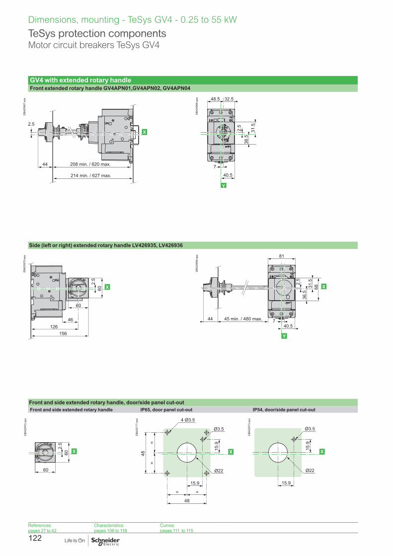
122
Dimensions, mounting - TeSys GV4 - 0.25 to 55 kW
TeSys protection componentsMotor circuit breakers TeSys GV4
GV4 with extended rotary handleFront extended rotary handle GV4APN01,GV4APN02, GV4APN04
208 min. / 620 max.
214 min. / 627 max.
X
44
2.5
DB4
2596
7.ep
s
Trip
O
I
36.5
40.5
32.548.5
7
2.5
6831.5
X
Y
DB4
2596
8.ep
s
Side (left or right) extended rotary handle LV426935, LV426936
46126
156
2.5
60
60 X
DB4
2597
0.ep
s
Trip
O
I
45 min. / 480 max.4440.5
7
2.5
81
36.5
31.5
68 X
Y
DB4
2596
9.ep
s
Front and side extended rotary handle, door/side panel cut-outFront and side extended rotary handle IP65, door panel cut-out IP54, door/side panel cut-out
2.5
60
60 X
DB4
2597
2.ep
s
15.9
4 Ø3.5
Ø3.5
Ø22
15.9
= =
48
==
48 X
DB4
2517
7.ep
s
15.9
Ø3.5
Ø22
15.9
X
DB4
2597
3.ep
s
References:pages 27 to 42
Characteristics:pages 106 to 118
Curves:pages 111 to 115
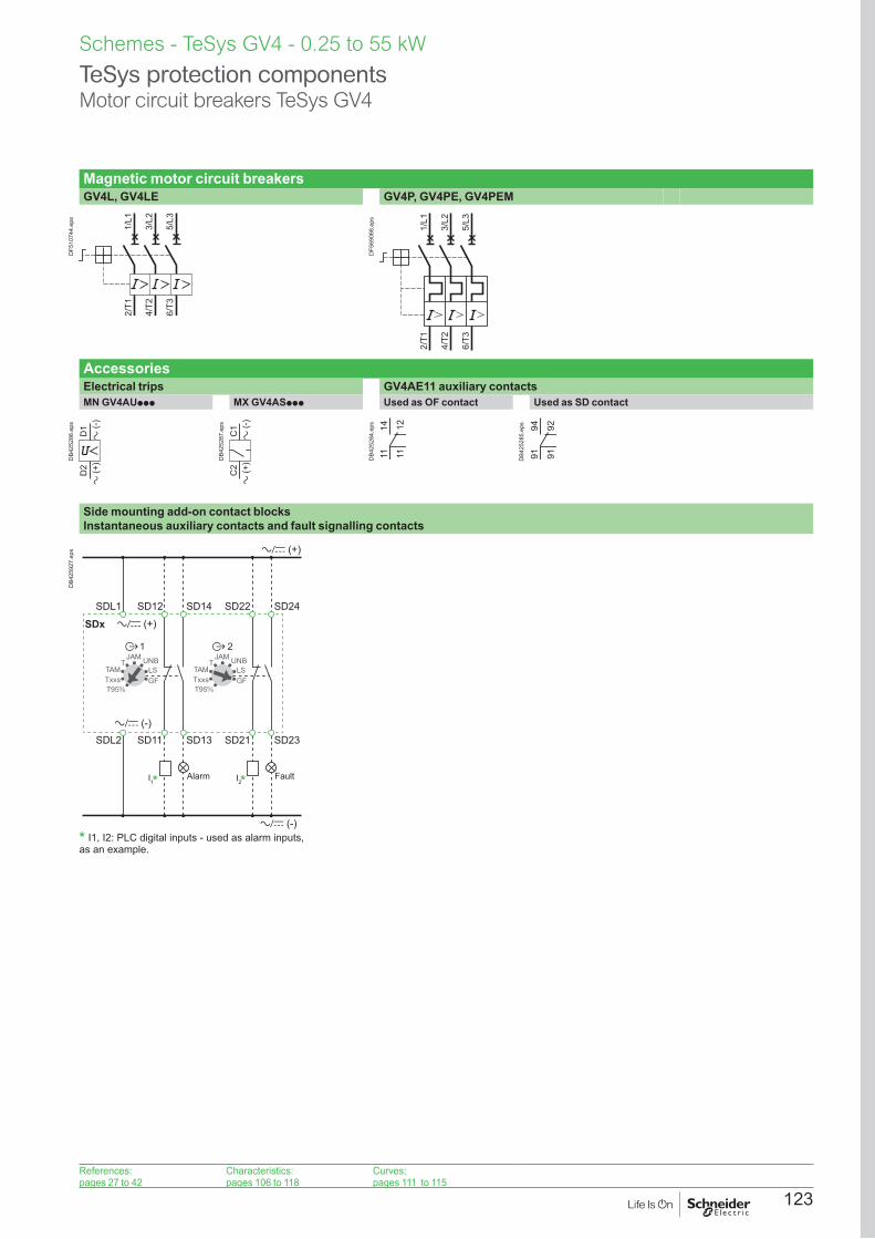
123
Magnetic motor circuit breakersGV4L, GV4LE GV4P, GV4PE, GV4PEM
2/T1
4/T2
6/T3
1/L1
3/L2
5/L3
DF5
1074
4.ep
s
2/T1
4/T2
6/T3
1/L1
3/L2
5/L3
DF5
6906
8.ep
sAccessoriesElectrical trips GV4AE11 auxiliary contactsMN GV4AUppp MX GV4ASppp Used as OF contact Used as SD contact
D1
D2
a (+
)a
(-)
DB4
2528
6.ep
s
a (+
)a
(-)
C1
C2
DB4
2528
7.ep
s
11 11
14 12
DB4
2528
4.ep
s
91 91
94 92
DB4
2528
5.ep
sSide mounting add-on contact blocks Instantaneous auxiliary contacts and fault signalling contacts
* *
* I1, I2: PLC digital inputs - used as alarm inputs,as an example.
T
T95%
TAMUNB
GF
JAM
LSTxxs
T
T95%
TAMUNB
GF
JAM
LSTxxs
a/c (+)
a/c (-)
a/c (-)
a/c (+)SDxSDL1 SD12 SD14 SD22 SD24
SDL2 SD11 SD13 SD21 SD23
Alarm FaultI1 I2
DB4
2592
7.ep
s
References:pages 27 to 42
Characteristics:pages 106 to 118
Curves:pages 111 to 115
Schemes - TeSys GV4 - 0.25 to 55 kW
TeSys protection componentsMotor circuit breakers TeSys GV4

124

125
TeSys GV755 to 110 kW

126
Characteristics - TeSys GV7 - 55 to 110 kW
TeSys protection componentsMotor circuit breakers TeSys GV7R
EnvironmentCircuit breaker type GV7R
Conforming to standards IEC/EN 60947-4-1 IEC/EN 60947-2UL 60947-4-1CSA C22.2 n° 60947-4-1
Product certifications UL, CSA, DNV-GLProtective treatment “TC”Degree of protection (front face)
Conforming to IEC 60529
Open mounted IP405 with terminal shroudsIn enclosure –
Shock resistance Conforming to IEC 60068-2-27 15 gn -11 msVibration resistance Conforming to IEC 60068-2-6 2.5 gn (25 Hz)Ambient air temperature Storage °C -55…+95
Operation Open mounted °C -25… +70In enclosure °C –
Temperature compensation Open mounted °C -25… +55 (3)
In enclosure °C –Flame resistance Conforming to IEC 60695-2-1 °C 960Maximum operating altitude m 2000Suitable for isolation Conforming to IEC 60947-1 § 7-1-6 YesResistance to mechanical impact J 0.5
–Sensitivity to phase failure
Technical characteristicsCircuit breaker type GV7Rp20...
Rp100GV7Rp150 GV7Rp220
Utilisation category Conforming to IEC 60947-2 AConforming to IEC 60947-4-1 AC-3
Rated operational voltage (Ue) Conforming to IEC 60947-2 V 690Rated insulation voltage (Ui) Conforming to IEC 60947-2 V 750Rated voltage Conforming to UL 60947-4-1,
CSA C22.2 n° 60947-4-1V 600
Rated operational frequency Conforming to IEC 60947-4-1 UL, CSA
Hz 50/60
Rated impulse withstand voltage (U imp) Conforming to IEC 60947-2 kV 8Total power dissipated per pole W 5 8.7 14.5Mechanical durability (C.O.: Close, Open) C.O. 50 000 40 000 20 000Electrical durability for AC-3 duty 415 V In C.O. 30 000 20 000 10 000Duty class (maximum operating rate) C.O./h 25Maximum conventional rated thermal current (Ith)
Conforming to IEC 60947-4-1 A 12…100 150 220
Rated duty Conforming to IEC 60947-4-1 Continuous duty(1) UL 60947-4-1 type E for GV2PppH7.(2) Leave a space of 9 mm between 2 circuit breakers: either an empty space, or side mounting add-on contact blocks. Side by side mounting is possible up to 40 °C.(3) For operation up to 70 °C, please consult your Regional Sales Office.
References:pages 45 to 50
Curves:pages 127 to 113
Dimensions:pages 134 to 136
Schemes:pages 137

127
Curves - TeSys GV7 - 55 to 110 kW
Thermal-magnetic tripping curves for GV7RAverage operating times at 20 °C related to multiples of the setting current
0,001
0,002
0,1
0,01
0,005
0,05
1
0,5
0,02
0,2
2
5
10
20
50
100
200
500
1000
2000
5000
10 000
102 3 4 7 10020 30 405 50 701
3
1
1,12
2
Time (s)
x the setting current (Ir)
DF5
1074
5.ep
s
1 Cold state curve2 Hot state curve3 12…14 Ir
In the event of total phase failure, tripping occurs after 4 s ± 20 %
TeSys protection componentsThermal-magnetic motor circuit breakers GV7R
References:pages 45 to 50
Characteristics:pages 126
Dimensions:pages 134 to 136
Schemes:pages 137

128
Curves - TeSys GV7 - 55 to 110 kW
TeSys protection componentsThermal-magnetic motor circuit breakers GV7R
Current limitation on short-circuit (3-phase 400/415 V)Dynamic stress
I peak = f (prospective Isc)
For GV7RE only
4102
5
7
60
20
10
50
100
30
3 4 6 10020 30 40 60
40
70
5 50
1
2
3
6
8
80
70
Limited peak current (kA)
Prospective Isc (kA)
DF5
3408
4.ep
s 1 GV7RE2202 GV7RE1503 GV7RE100
For GV7RS only
4102
5
7
60
20
10
50
100
30
3 4 6 10020 30 40 60
40
70
5 50
6
8
80
1
2
3
70
Limited peak current (kA)
Prospective Isc (kA)
DF5
3408
3.ep
s 1 GV7RS2202 GV7RS1503 GV7RS100
References:pages 45 to 50
Characteristics:pages 126
Dimensions:pages 134 to 136
Schemes:pages 137

129
Curves - TeSys GV7 - 55 to 110 kW
TeSys protection componentsThermal-magnetic motor circuit breakers GV7R
Thermal limit (3-phase 400/415 V)Thermal limit
Sum of I2dt = f (prospective Isc)
For GV7RE only
2x10⁴
102
3x10⁴
5x10⁴
2x10⁶
2x10⁵
105
106
107
5x10⁶
3x10⁵
3 4 6 10020 30 40 60
5x10⁵
3x10⁶
5 50 70
1
2
3
Sum of I2dt (A2s)
Prospective Isc (kA)
DF5
3408
5.ep
s 1 GV7RE2202 GV7RE1503 GV7RE100
For GV7RS only
2x10⁴
102
3x10⁴
5x10⁴
2x10⁶
2x10⁵
105
106
107
5x10⁶
3x10⁵
3 4 6 10020 30 40 60
5x10⁵
3x10⁶
5 50 70
1
2
3
Sum of I2dt (A2s)
Prospective Isc (kA)
DF5
3408
6.ep
s 1 GV7RS2202 GV7RS1503 GV7RS100
References:pages 45 to 50
Characteristics:pages 126
Dimensions:pages 134 to 136
Schemes:pages 137

130
TeSys protection componentsThermal-magnetic motor circuit breakers GV7R
Current limitation on short-circuit (3-phase 690 V)Dynamic stress
I peak = f (prospective Isc)
For GV7RE only
4102
5
6
30
10
8
20
50
40
3 4 6 205
12
7
9
Limited peak current (kA)
Prospective Isc (kA)
DF5
3408
7.ep
s 1 GV7RE2202 GV7RE150 and GV7RE100
For GV7RS only
4102
5
6
30
10
8
20
50
40
3 4 6 205
12
7
Limited peak current (kA)
Prospective Isc (kA)
DF5
3408
8.ep
s 1 GV7RS2202 GV7RS150 and GV7RS100
References:pages 45 to 50
Characteristics:pages 126
Dimensions:pages 134 to 136
Schemes:pages 137
Curves - TeSys GV7 - 55 to 110 kW

131
TeSys protection componentsThermal-magnetic motor circuit breakers GV7R
Thermal limit on short-circuit (3-phase 690 V)Thermal limit
Sum of I2dt = f (prospective Isc)
For GV7RE only
102 3 4 6 205
2x10⁶
2x10⁵
105
106
3x10⁵
5x10⁵
3x10⁶
1
2
8
Sum of I2dt (A2s)
Prospective Isc (kA)
DF5
3408
9.ep
s 1 GV7RE2202 GV7RE150 and GV7RE100
For GV7RS only
102 3 4 6 205
2x10⁶
2x10⁵
105
106
3x10⁵
5x10⁵
3x10⁶
1
2
Sum of I2dt (A2s)
Prospective Isc (kA)
DF5
3409
0.ep
s 1 GV7RS2202 GV7RS150 and GV7RS100
References:pages 45 to 50
Characteristics:pages 126
Dimensions:pages 134 to 136
Schemes:pages 137
Curves - TeSys GV7 - 55 to 110 kW

132
Characteristics of GV7 electric tripsType of trip GV7AUppp
MN undervoltage tripGV7ASppp MX shunt trip
Rated insulation voltage (Ui) Conforming to IEC 60947-1
V 690 690
Conforming to CSA C22-2 n°14, UL 508
V 600 600
Operational voltage (Ue) Conforming to IEC 60947-1
V 0.85...1.1 Uc 0.7...1.1 Uc
Drop-out voltage V 0.7...0.35 Uc 0.7...0.35 Uc
Inrush consumption a VA < 10
Sealed consumption a VA < 5
Operating time Conforming to IEC 60947-1
ms
From the moment the voltage reaches its operational value until opening of the circuit breaker. < 50
On-load factor 100 %
Cabling (spring connection)
Number of conductors 1
Solid cable mm2 1.5
Flexible cable without cable end
mm2 1.5
Flexible cable with cable end
mm2 1
Tightening torque N.m 1.2
Mechanical durability (C.O.: Close - Open)
C.O. 50 % of the mechanical durability of the circuit breaker.
TeSys protection componentsGV7 motor circuit breakersElectric trips
Dimensions, mounting - TeSys GV7 - 55 to 110 kW

133
Dimensions, mounting - TeSys GV7 - 55 to 110 kW
Auxiliary contact characteristicsType of contacts GV7AE11 GV7AB11
Rated insulation voltage(Ui) (associated insulation coordination)
Conforming to IEC 60947-1 V 690 690
Conventional thermal current (Ith)
Conforming to IEC 60947-5-1 A 6 6
Mechanical durability (C.O.: Close - Open)
C.O. 50 000 50 000
Operational current conforming to IEC 60947-5-1 a.c. operation
AC-12 or AC-15. 50 000 C.O. AC-12 or AC-15. 50 000 C.O.Rated operational voltage (Ue)
V 24 48 110 230/ 240
380/ 415
440 690 24 48 110 230/ 240
380/ 415
440 690
Rated operational current (Ie)
AC-12 A 6 6 6 6 6 6 6 5 5 5 5 5 5 5
AC-15 A 6 6 5 4 3 3 0.1 5 5 4 3 2.5 2.5 0.1
Operational current conforming to IEC 60947-5-1 d.c. operation
DC-12 or DC-14. 50 000 C.O. DC-12 or DC-14. 50 000 C.O.Rated operational voltage (Ue)
V 24 48 110 250 24 48 110 250
Rated operational current (Ie)
DC-12 A 2.5 2.5 0.8 0.3 2 2 0.5 –
DC-14 A 1 0.2 0.5 0.03 0.5 0.1 0.25 –
Minimum operational conditionsd.c. operation
V 17 12
mA 5 5
Short-circuit protection By GB2CBpp circuit breaker (rating according to operational current for Ue y 415 V) or gG fuse, 10 A max.
Cabling Solid cable mm2 1 x 1.5 conductor 1 x 1.5 conductor
Flexible cable without cable end mm2 1 x 1.5 conductor 1 x 1.5 conductor
Flexible cable with cable end mm2 1 x 1.5 conductor 1 x 1.5 conductor
TeSys protection componentsThermal-magnetic motor circuit breakers GV7Auxiliary contacts

134
Dimensions, mounting - TeSys GV7 - 55 to 110 kW
TeSys protection componentsThermal-magnetic motor circuit breakers GV7R
GV7RDimensions
8186
111 (1)
=16
1=
=
=12
5=
105
= =35
=
DF5
6905
1.ep
s
(1) 126 for GV7Rp220.
Motor circuit breakers with terminal shields or phase barriers GV7R + GV7AC01 or AC04
DF5
6905
2.ep
s
(2) Phase barriers: GV7AC04.(3) Terminal shields: GV7AC01.
Combination of GV7R and TeSys contactor LC1 F with kit GV7AC0p Minimum electrical clearanceac
b
DF5
6905
3.ep
s
x1x1
x2x2
DF5
6905
4.ep
s
a b cGV7R + LC1F115 or F150 + GV7AC06
119 334 181
GV7R + LC1F185 + GV7AC06
119 338 188
GV7R + LC1F225 + GV7AC07
131 358 188
GV7R + LC1F265 + GV7AC07
131 364 215
Minimum distance between 2 circuit breakers mounted side by side = 0
x1 x2Painted or insulated metal plate, insulation or insulated bar
0 30
Bare metal plate
U y 440 V 5 35440 V < U < 600 V 10 35U u 600 V 20 35
References:pages 45 to 50
Characteristics:pages 126
Curves:pages 127 to 113
Schemes:pages 137

135
Dimensions, mounting - TeSys GV7 - 55 to 110 kW
TeSys protection componentsThermal-magnetic motor circuit breakers GV7R
GV7RPanel mounting Mounting on 2 mounting rails DZ5 MB201
35
=12
5
35 35
=
DF5
6905
6.ep
s
135
35
125
DZ5 ME5
15D
F569
057.
eps
Flush-mounting1 circuit breaker GV7R n circuit breakers GV7R
side by side
=
29
=29
4776
88 83
==
108
= =108
==
108
DF5
6905
8.ep
s
Combination of GV7R and TeSys contactor LC1F with kit GV7 AC0p
G
EH
DF5
6905
5.ep
s
E G HGV7R + LC1F115 + GV7AC06 44 85 120GV7R + LC1F150 + GV7AC06 46 85 120GV7R + LC1F185 + GV7AC06 48 85 120GV7R + LC1F225 + GV7AC07 57 85 120GV7R + LC1F265 + GV7AC07 60 85 120
References:pages 45 to 50
Characteristics:pages 126
Curves:pages 127 to 113
Schemes:pages 137

136
Dimensions, mounting - TeSys GV7 - 55 to 110 kW
TeSys protection componentsThermal-magnetic motor circuit breakers GV7R
GV7RSpreaders GV7AC03 Connection
45 45114
30 41
DF5
6905
9.ep
s Z
X
DF5
6906
0.ep
s
Smooth terminals Connectors
X
7010
,5 Z
70
Z
X
19
a
DF5
6906
1.ep
s
aGV7Rp40…Rp150 19.5GV7Rp220 21.5
Direct rotary handle GV7AP03, GV7AP04Flush-mounting
7345
28
155121
0
I
5591
36
DF5
6906
2.ep
s
=
29
=97
4776
89
DF5
6906
3.ep
s
Direct rotary handle GV7AP03 or GV7AP04 with conversion accessory GV7AP05Front face cut-out Enclosure viewed from top
=
41
=100
5910
0
69
=
51120
=12
0
125 ±2
e
9
9,25
DF5
6906
4.ep
s
hD
F569
065.
eps
Door cut-outs require a minimum distance between the centre of the circuit breaker and the door hinge point D u 100 + (h x 5)
e = 1 to 3 maxExtended rotary handle GV7AP01, GV7AP02
75=
60
60
0
I
=
75=
=
l
9
9,25
DF5
6906
6.ep
s
l : 185 min, 600 maxThe shaft of the extended rotary handle GV7AP01 or GV7AP02 must be cut to length: l – 126 mm.
References:pages 45 to 50
Characteristics:pages 126
Curves:pages 127 to 113
Schemes:pages 137

137
Schemes - TeSys GV7 - 55 to 110 kW
TeSys protection componentsThermal-magnetic motor circuit breakers GV7 R
SchemesMotor circuit breakers Add-on auxiliary contacts according to their location (1)
GV7 R GV7 AE11, GV7 AB11
2/T1
4/T2
6/T3
1/L1
3/L2
5/L3
DF5
6909
8.ep
s Location 1C/O contact
Location 2 Trip indication
Location 3 Electrical fault indication
Location 4 C/O contact
1114 12
DF5
6909
9.ep
s
9194 92
DF5
6910
0.ep
s
8184 82
DF5
6910
1.ep
s
2124 22
DF5
6910
2.ep
s
A self-adhesive label, supplied with the contact, can be affixed to the front face of the circuit-breaker to allow personalised marking according to the function of the contact or contacts.(1) See page 109.
Electric tripsGV7AUppp GV7ASppp GV7AD111, AD112
D1
D4D
F569
103.
eps
C1
C2D
F569
104.
eps
9897 50 ms
DF5
6910
5.ep
s
Recommended application schemes GV7AD111, AD112Fault indication Contactor opening on overload
9897 50 ms
– KA1
2324
1314
– KA1
Reset
Overload fault
DF5
6910
6.ep
s
9897 50 ms
– KM1– KA1
A1A2
A1A2
B1
– KA1
2122
ResetDF5
6910
7.ep
s
Associated componentsKA1: CA2KN or CADN
Associated componentsKA1: CAD + LAD6K10 or RHKKM1: LC1 D or LC1 F
References:pages 45 to 50
Characteristics:pages 126
Curves:pages 127 to 113
Dimensions:pages 134 to 136

138
139
TeSys GB20.5 to 20 A (for equipment and control circuits)

140
EnvironmentCircuit breaker type GB2CB GB2CD GB2DB GB2CS
Conforming to standards IEC 60947-1, 947-2, EN 60947-1, 60947-2Product certifications CSA, NEMKO, UL NEMKO, UL – –Protective treatment “TC”Degree of protection Conforming to IEC 60529 IP 20Shock resistance Conforming to IEC 60068-2-27 22 gn for 20 msVibration resistance Conforming to IEC 60068-2-6 5 gn (5…110 Hz)Ambient air temperature around the device
Storage °C -40…+80Operation °C -20…+60
Flame resistance Conforming to IEC 60695-2-1 °C 960Maximum operating altitude m 3000
Operating position In relation to normal vertical mounting plane
DF5
3426
5.ep
s
GB2CB,CD, CS GB2DB
Cabling Minimum c.s.a. Maximum c.s.a.Solid cable mm2 1 x 0.75 1 x 6 or 2 x 4Flexible cable with cable end mm2 1 x 0.75 1 x 4 or 2 x 2.5
Tightening torque N.m 1.2
Technical characteristicsUtilisation category Conforming to IEC 60947-2 A A A ARated operational voltage (Ue)
Conforming to IEC 60947-2 V 250 (1) 250 415 250 (1)
Conforming to CSA C22-2 Nr 14 and UL 1077
V 277 – 277 –
Rated operational frequency Conforming to IEC 60947-2 Hz 50/60 50/60 50/60 50/60Rated impulse withstand voltage (U imp)
Conforming to IEC 60947-2 kV 4 4 4 4
Total power dissipated per pole W 2 2 2 1.9Mechanical and electrical durability
C.O.: Closing - Opening C.O. 8000 8000 8000 8000
Operational current correction coefficient (a or c)
According to the permissible ambient temperature
°C -20 -10 0 +10 +20 +30 +40 +50 +60
Correction coefficient 1.2 1.15 1.1 1.05 1 0.95 0.90 0.85 0.80Tripping threshold Of the magnetic trips 12…16 In 12…16 In 12…16 In 5…7 In
(1) Ue = 415 V when a GB2 circuit breaker is fitted on every live conductor.
Tripping curvesAverage operating time at 20 °C without prior current flow (cold state)
GB2CB, GB2 CD, GB2 DB GB2CS
1,051,5
2 3 4 5 6 810
1
52
2010
10050
1
52
2010
1
52
2010
60120
500200
100 x In1,051,5
2 3 4 5 6 810
1
52
2010
10050
1
52
2010
1
52
2010
60120
500200
100 x In
Milli
seco
nds
Seco
nds
Min
utes
DF5
3426
6.ep
s
1,051,5
2 3 4 5 6 810
1
52
2010
10050
1
52
2010
1
52
2010
60120
500200
100 x In
Milli
seco
nds
Seco
nds
Min
utes
DF5
3426
7.ep
s
Protection componentsThermal-magnetic circuit breakers TeSys GB2 for the protection of industrial equipment control circuits
Characteristics - TeSys GB
References:pages 51 to 54
Dimensions:pages 143
Schemes:pages 143

141
Circuit breaker type GB2CB05 CB06 CB07 CB08 CB09 CB10 CB12 CB14 CB16 CB20 CB21 CB22
Rating A 0.5 1 2 3 4 5 6 8 10 12 16 20
Breaking capacity conforming to IEC 60947-2 a 50/60 Hz
110 V Icu kA 50 50 15 10 6 3 3 3 2 2 2 2Ics % (1) 100 50 50 50 50 75 75 75 75 75 75 75
230/240 V Icu kA 50 50 15 3 3 2 1.5 1.5 1.5 1.5 1.5 1.5Ics % (1) 25 25 25 50 50 75 75 75 75 75 75 75
Associated fuses, if required if Isc > breaking capacity Icu conforming to IEC 60947-2
110 V aM A g g 20 25 25 40 40 50 50 63 63 63gG A g g 25 32 32 50 50 63 63 80 80 80
230/240 V aM A g g 16 20 20 32 32 40 40 50 50 50gG A g g 25 32 32 40 40 50 50 63 63 63
Circuit breaker type GB2CD05 CD06 CD07 CD08 CD09 CD10 CD12 CD14 CD16 CD20 CD21 CD22
Rating A 0.5 1 2 3 4 5 6 8 10 12 16 20
Breaking capacity conforming to IEC 60947-2 a 50/60 Hz
110 V Icu kA 50 50 15 10 6 3 3 3 2 2 2 2Ics % (1) 100 50 50 50 50 75 75 75 75 75 75 75
230/240 V Icu kA 50 50 15 3 3 2 1.5 1.5 1.5 1.5 1.5 1.5Ics % (1) 25 25 25 50 50 75 75 75 75 75 75 75
Associated fuses, if required if lsc > breaking capacity Icu conforming to IEC 60947-2
110 V aM A g g 20 25 25 40 40 50 50 63 63 63gG A g g 25 32 32 50 50 63 63 80 80 80
230/240 V aM A g g 16 20 20 32 32 40 40 50 50 50gG A g g 25 32 32 40 40 50 50 63 63 63
Circuit breaker type GB2DB05 DB06 DB07 DB08 DB09 DB10 DB12 DB14 DB16 DB20 DB21 DB22
Rating A 0.5 1 2 3 4 5 6 8 10 12 16 20
Breaking capacity conforming to IEC 60947-2 a 50/60 Hz
110 V lcu kA 50 50 15 10 6 3 3 3 2 2 2 2Ics % (1) 100 50 50 50 50 75 75 75 75 75 75 75
230/240 V lcu kA 50 50 15 3 3 2 1.5 1.5 1.5 1.5 1.5 1.5Ics % (1) 25 25 25 50 50 75 75 75 75 75 75 75
400/415 V lcu kA 50 50 15 3 3 2 1.5 1.5 1.5 1.5 1.5 1.5Ics % (1) 25 25 25 50 50 75 75 75 75 75 75 75
Associated fuses, if required if lsc > breaking capacity Icu conforming to IEC 60947-2
110 V aM A g g 20 25 25 40 40 50 50 63 63 63gG A g g 25 32 32 50 50 63 63 80 80 80
230/240 V aM A g g 16 20 20 32 32 40 40 50 50 50gG A g g 25 32 32 40 40 50 50 63 63 63
400/415 V aM A g g 16 20 20 32 32 40 40 50 50 50gG A g g 25 32 32 40 40 50 50 63 63 63
(1) As % of Icu.g Fuse not required. Breaking capacity Icu > lsc.
Protection componentsThermal-magnetic circuit breakers TeSys GB2 for the protection of industrial equipment control circuits
Characteristics - TeSys GB
References:pages 51 to 54
Dimensions:pages 143
Schemes:pages 143

142
Circuit breaker type GB2pp05 pp06 pp07 pp08 pp09 pp10 pp12 pp14 pp16 pp20 pp21 pp22
Breaking capacity (lcu) conforming to IEC 60947-2 c
24 V kA 1.5 1.5 1.5 1.5 1.5 1.5 1.5 1.5 1.5 1.5 1.5 1.548 V kA 1 1 1 1 1 1 1 1 – – – –
Operational current conforming to IEC 60947-5-1 c
DC-12 24 V A 0.5 1 2 3 4 5 6 8 10 12 16 2048 V A 0.5 1 2 3 4 5 6 8 10 12 16 20
DC-13 24 V A 0.5 1 2 3 4 5 6 8 10 12 16 2048 V A 0.5 1 2 3 4 5 6 8 – – – –
Circuit breaker type GB2CS05 CS06
Rating A 0.5 1
Breaking capacity conforming to IEC 60947-2 a 50/60 Hz
110 V lcu kA 50 50lcs % (1) 100 100
230/240 V lcu kA 50 50lcs % (1) 25 25
400/415 V (2)
lcu kA 50 50lcs % (1) 25 25
Breaking capacity (lcu) conforming to IEC 60947-2 c
24 V kA 1.5 1.548 V kA 1 1
Operational current conforming to IEC 60947-5-1 c
DC-12 24 V A 0.5 148 V A 0.5 1
DC-13 24 V A 0.5 148 V A 0.5 1
Maximum permissible line length for star-delta starting (length of cable containing 2 or more conductors)
With contactors LCp D09 …D18
Operational voltage V 48 110 230 48 110 230
C.s.a. 0.60 mm2 m (3) 31 365 6 85 2300.75 mm2 m (3) 39 460 8 110 2901 mm2 m (3) 52 610 10 145 3801.5 mm2 m (3) 78 910 15 220 5702.5 mm2 m (3) 130 1520 26 360 9504 mm2 m (3) 200 2400 41 580 1500
With contactors LCp D25…D32
Operational voltage V 48 110 230 48 110 230
C.s.a. 0.60 mm2 m (3) (3) 230 (3) 56 2300.75 mm2 m (3) (3) 290 (3) 70 2901 mm2 m (3) (3) 390 (3) 95 3801.5 mm2 m (3) (3) 580 (3) 140 5702.5 mm2 m (3) (3) 970 (3) 230 9504 mm2 m (3) (3) 1500 (3) 375 1500
With contactors LCp D40…D80
Operational voltage V 48 110 230 48 110 230
C.s.a. 0.60 mm2 m (3) (3) 46 (3) 13 1000.75 mm2 m (3) (3) 60 (3) 17 1301 mm2 m (3) (3) 80 (3) 22 1701.5 mm2 m (3) (3) 120 (3) 34 2502.5 mm2 m (3) (3) 190 (3) 56 4204 mm2 m (3) (3) 310 (3) 90 680
(1) As % of Icu.(2) One GB2CS circuit breaker on each live conductor.(3) Use relays.
Protection componentsThermal-magnetic circuit breakers TeSys GB2 for the protection of industrial equipment control circuits
Characteristics - TeSys GB
References:pages 51 to 54
Dimensions:pages 143
Schemes:pages 143

143
DimensionsGB2CBpp, GB2CDpp, GB2CSpp GB2DBpp
74
1582
82
75
79
67
DF5
3427
2.ep
s
30
74
85
85
78
82
70D
F534
273.
eps
Marking: up to twelve AB1 R clip-in markers.
SchemesGB2CBpp GB2CDpp GB2DBpp GB2CSpp
2/T
11/
L1
DF5
3427
4.ep
s
2/T
11/
L1
3/L2
(13
) 4
/T2
( 14)
DF5
3427
5.ep
s
1/L1
3/L2
2/T
1
4/T
2
DF5
3427
6.ep
s
2/T
11/
L1
DF5
3427
7.ep
s
Protection componentsThermal-magnetic circuit breakers TeSys GB2 for the protection of industrial equipment control circuits
Dimensions, schemes - TeSys GB
References:pages 51 to 54
Characteristics:pages 140 to 142
Schemes:pages 143

144


Schneider Electric Industries SAS
35, rue Joseph MonierCS 3032392506 Rueil Malmaison Cedex France
RCS Nanterre 954 503 439Capital social 896 313 776 €www.schneider-electric.com
06-2017
© 2017 - Schneider Electric. All Rights Reserved.All trademarks are owned by Schneider Electric Industries SAS or its affiliated companies.Document reference: LVCATESGV_EN This document has been
printed on recycled paper