TeSys T DTM for FDT Container - Online Help
378
1672614EN www.schneider-electric.com TeSys T DTMfor FDTContainer 1672614EN 09/2014 TeSys T DTM for FDT Container Online Help 09/2014
-
Upload
khangminh22 -
Category
Documents
-
view
0 -
download
0
Transcript of TeSys T DTM for FDT Container - Online Help

TeSys T DTM for FDT Container
1672614EN 09/2014
167
2614
EN
www.schneider-electric.com
TeSys T DTM for FDT ContainerOnline Help
09/2014

The information provided in this documentation contains general descriptions and/or technical character-istics of the performance of the products contained herein. This documentation is not intended as a substitute for and is not to be used for determining suitability or reliability of these products for specific user applications. It is the duty of any such user or integrator to perform the appropriate and complete risk analysis, evaluation and testing of the products with respect to the relevant specific application or use thereof. Neither Schneider Electric nor any of its affiliates or subsidiaries shall be responsible or liable for misuse of the information contained herein. If you have any suggestions for improvements or amendments or have found errors in this publication, please notify us.
No part of this document may be reproduced in any form or by any means, electronic or mechanical, including photocopying, without express written permission of Schneider Electric.
All pertinent state, regional, and local safety regulations must be observed when installing and using this product. For reasons of safety and to help ensure compliance with documented system data, only the manufacturer should perform repairs to components.
When devices are used for applications with technical safety requirements, the relevant instructions must be followed.
Failure to use Schneider Electric software or approved software with our hardware products may result in injury, harm, or improper operating results.
Failure to observe this information can result in injury or equipment damage.
© 2014 Schneider Electric. All rights reserved.
2 1672614EN 09/2014

Table of Contents
Safety Information . . . . . . . . . . . . . . . . . . . . . . . . . . . . . . . . . . . . . . . . . . . 9About the Book. . . . . . . . . . . . . . . . . . . . . . . . . . . . . . . . . . . . . . . . . . . . . . 13
Chapter 1 Presentation of the TeSys T DTM . . . . . . . . . . . . . . . . . . . . . . . . . . . . . . . 151.1 Introduction . . . . . . . . . . . . . . . . . . . . . . . . . . . . . . . . . . . . . . . . . . . . . . . . . . . . . . . . . . . . . . 16
Presentation of the TeSys T Motor Management System. . . . . . . . . . . . . . . . . . . . . . . . . . . 17Definitions . . . . . . . . . . . . . . . . . . . . . . . . . . . . . . . . . . . . . . . . . . . . . . . . . . . . . . . . . . . . . . . 22Installing SoMove and the TeSys DTM Library . . . . . . . . . . . . . . . . . . . . . . . . . . . . . . . . . . . 23Installing Update TeSys DTM Library . . . . . . . . . . . . . . . . . . . . . . . . . . . . . . . . . . . . . . . . . . 24
1.2 User Interface . . . . . . . . . . . . . . . . . . . . . . . . . . . . . . . . . . . . . . . . . . . . . . . . . . . . . . . . . . . . 25General Description. . . . . . . . . . . . . . . . . . . . . . . . . . . . . . . . . . . . . . . . . . . . . . . . . . . . . . . . 26Menu Bar and Tool Bar . . . . . . . . . . . . . . . . . . . . . . . . . . . . . . . . . . . . . . . . . . . . . . . . . . . . . 28Command Submenu . . . . . . . . . . . . . . . . . . . . . . . . . . . . . . . . . . . . . . . . . . . . . . . . . . . . . . . 31Password Management. . . . . . . . . . . . . . . . . . . . . . . . . . . . . . . . . . . . . . . . . . . . . . . . . . . . . 32Device Version Management . . . . . . . . . . . . . . . . . . . . . . . . . . . . . . . . . . . . . . . . . . . . . . . . 33Status Bar and Synchronization Data Bar . . . . . . . . . . . . . . . . . . . . . . . . . . . . . . . . . . . . . . . 34my Device Tab . . . . . . . . . . . . . . . . . . . . . . . . . . . . . . . . . . . . . . . . . . . . . . . . . . . . . . . . . . . 36operate Tab . . . . . . . . . . . . . . . . . . . . . . . . . . . . . . . . . . . . . . . . . . . . . . . . . . . . . . . . . . . . . 37Tab Zone . . . . . . . . . . . . . . . . . . . . . . . . . . . . . . . . . . . . . . . . . . . . . . . . . . . . . . . . . . . . . . . . 39parameter list Tab . . . . . . . . . . . . . . . . . . . . . . . . . . . . . . . . . . . . . . . . . . . . . . . . . . . . . . . . 42fault Tab . . . . . . . . . . . . . . . . . . . . . . . . . . . . . . . . . . . . . . . . . . . . . . . . . . . . . . . . . . . . . . . . 44monitoring Tab. . . . . . . . . . . . . . . . . . . . . . . . . . . . . . . . . . . . . . . . . . . . . . . . . . . . . . . . . . . 45diagnostic Tab . . . . . . . . . . . . . . . . . . . . . . . . . . . . . . . . . . . . . . . . . . . . . . . . . . . . . . . . . . . 47
Chapter 2 Metering and Monitoring Functions . . . . . . . . . . . . . . . . . . . . . . . . . . . . . 492.1 Measurement. . . . . . . . . . . . . . . . . . . . . . . . . . . . . . . . . . . . . . . . . . . . . . . . . . . . . . . . . . . . . 50
Line Currents . . . . . . . . . . . . . . . . . . . . . . . . . . . . . . . . . . . . . . . . . . . . . . . . . . . . . . . . . . . . . 51Ground Current . . . . . . . . . . . . . . . . . . . . . . . . . . . . . . . . . . . . . . . . . . . . . . . . . . . . . . . . . . . 52Average Current . . . . . . . . . . . . . . . . . . . . . . . . . . . . . . . . . . . . . . . . . . . . . . . . . . . . . . . . . . 54Current Phase Imbalance . . . . . . . . . . . . . . . . . . . . . . . . . . . . . . . . . . . . . . . . . . . . . . . . . . . 55Thermal Capacity Level. . . . . . . . . . . . . . . . . . . . . . . . . . . . . . . . . . . . . . . . . . . . . . . . . . . . . 56Motor Temperature Sensor . . . . . . . . . . . . . . . . . . . . . . . . . . . . . . . . . . . . . . . . . . . . . . . . . . 57Frequency . . . . . . . . . . . . . . . . . . . . . . . . . . . . . . . . . . . . . . . . . . . . . . . . . . . . . . . . . . . . . . . 58Line-to-Line Voltages. . . . . . . . . . . . . . . . . . . . . . . . . . . . . . . . . . . . . . . . . . . . . . . . . . . . . . . 59Line Voltage Imbalance . . . . . . . . . . . . . . . . . . . . . . . . . . . . . . . . . . . . . . . . . . . . . . . . . . . . . 60Average Voltage . . . . . . . . . . . . . . . . . . . . . . . . . . . . . . . . . . . . . . . . . . . . . . . . . . . . . . . . . . 61Power Factor . . . . . . . . . . . . . . . . . . . . . . . . . . . . . . . . . . . . . . . . . . . . . . . . . . . . . . . . . . . . . 62Active Power and Reactive Power . . . . . . . . . . . . . . . . . . . . . . . . . . . . . . . . . . . . . . . . . . . . 63Active Power Consumption and Reactive Power Consumption . . . . . . . . . . . . . . . . . . . . . . 64
2.2 System and Device Monitoring Faults . . . . . . . . . . . . . . . . . . . . . . . . . . . . . . . . . . . . . . . . . . 65Controller Internal Fault . . . . . . . . . . . . . . . . . . . . . . . . . . . . . . . . . . . . . . . . . . . . . . . . . . . . . 66Controller Internal Temperature . . . . . . . . . . . . . . . . . . . . . . . . . . . . . . . . . . . . . . . . . . . . . . 67Control Command Error Diagnostic . . . . . . . . . . . . . . . . . . . . . . . . . . . . . . . . . . . . . . . . . . . 68Wiring Faults . . . . . . . . . . . . . . . . . . . . . . . . . . . . . . . . . . . . . . . . . . . . . . . . . . . . . . . . . . . . . 70Configuration Checksum . . . . . . . . . . . . . . . . . . . . . . . . . . . . . . . . . . . . . . . . . . . . . . . . . . . . 72Communication Loss . . . . . . . . . . . . . . . . . . . . . . . . . . . . . . . . . . . . . . . . . . . . . . . . . . . . . . . 73Time to Trip . . . . . . . . . . . . . . . . . . . . . . . . . . . . . . . . . . . . . . . . . . . . . . . . . . . . . . . . . . . . . . 75LTM R Configuration Fault . . . . . . . . . . . . . . . . . . . . . . . . . . . . . . . . . . . . . . . . . . . . . . . . . . 76LTM E Configuration Fault and Warning . . . . . . . . . . . . . . . . . . . . . . . . . . . . . . . . . . . . . . . . 77External Fault . . . . . . . . . . . . . . . . . . . . . . . . . . . . . . . . . . . . . . . . . . . . . . . . . . . . . . . . . . . . 78
1672614EN 09/2014 3

2.3 Fault and Warning Counters . . . . . . . . . . . . . . . . . . . . . . . . . . . . . . . . . . . . . . . . . . . . . . . . . 79Introducing Fault and Warning Counters . . . . . . . . . . . . . . . . . . . . . . . . . . . . . . . . . . . . . . . . 80All Faults Counter. . . . . . . . . . . . . . . . . . . . . . . . . . . . . . . . . . . . . . . . . . . . . . . . . . . . . . . . . . 81All Warnings Counter . . . . . . . . . . . . . . . . . . . . . . . . . . . . . . . . . . . . . . . . . . . . . . . . . . . . . . . 82Auto-Reset Counter . . . . . . . . . . . . . . . . . . . . . . . . . . . . . . . . . . . . . . . . . . . . . . . . . . . . . . . . 83Protection Faults and Warnings Counters . . . . . . . . . . . . . . . . . . . . . . . . . . . . . . . . . . . . . . . 84Control Command Errors Counter . . . . . . . . . . . . . . . . . . . . . . . . . . . . . . . . . . . . . . . . . . . . . 85Wiring Faults Counter . . . . . . . . . . . . . . . . . . . . . . . . . . . . . . . . . . . . . . . . . . . . . . . . . . . . . . 86Communication Loss Counters . . . . . . . . . . . . . . . . . . . . . . . . . . . . . . . . . . . . . . . . . . . . . . . 87Internal Fault Counters. . . . . . . . . . . . . . . . . . . . . . . . . . . . . . . . . . . . . . . . . . . . . . . . . . . . . . 88Fault History . . . . . . . . . . . . . . . . . . . . . . . . . . . . . . . . . . . . . . . . . . . . . . . . . . . . . . . . . . . . . . 89
2.4 Motor History . . . . . . . . . . . . . . . . . . . . . . . . . . . . . . . . . . . . . . . . . . . . . . . . . . . . . . . . . . . . . 90Motor Starts Counters . . . . . . . . . . . . . . . . . . . . . . . . . . . . . . . . . . . . . . . . . . . . . . . . . . . . . . 91Motor Starts Per Hour Counter . . . . . . . . . . . . . . . . . . . . . . . . . . . . . . . . . . . . . . . . . . . . . . . 92Load Sheddings Counter . . . . . . . . . . . . . . . . . . . . . . . . . . . . . . . . . . . . . . . . . . . . . . . . . . . . 93Auto Restart Counters . . . . . . . . . . . . . . . . . . . . . . . . . . . . . . . . . . . . . . . . . . . . . . . . . . . . . . 94Motor Last Start Current Ratio . . . . . . . . . . . . . . . . . . . . . . . . . . . . . . . . . . . . . . . . . . . . . . . . 95Motor Last Start Duration . . . . . . . . . . . . . . . . . . . . . . . . . . . . . . . . . . . . . . . . . . . . . . . . . . . . 96Operating Time . . . . . . . . . . . . . . . . . . . . . . . . . . . . . . . . . . . . . . . . . . . . . . . . . . . . . . . . . . . 97
2.5 System Operating Status . . . . . . . . . . . . . . . . . . . . . . . . . . . . . . . . . . . . . . . . . . . . . . . . . . . . 98Motor State. . . . . . . . . . . . . . . . . . . . . . . . . . . . . . . . . . . . . . . . . . . . . . . . . . . . . . . . . . . . . . . 99Minimum Wait Time . . . . . . . . . . . . . . . . . . . . . . . . . . . . . . . . . . . . . . . . . . . . . . . . . . . . . . . . 100
Chapter 3 Motor Protection Functions . . . . . . . . . . . . . . . . . . . . . . . . . . . . . . . . . . . 1013.1 Motor Protection Functions Introduction . . . . . . . . . . . . . . . . . . . . . . . . . . . . . . . . . . . . . . . . 102
Definitions . . . . . . . . . . . . . . . . . . . . . . . . . . . . . . . . . . . . . . . . . . . . . . . . . . . . . . . . . . . . . . . 103Motor Protection Characteristics . . . . . . . . . . . . . . . . . . . . . . . . . . . . . . . . . . . . . . . . . . . . . . 104
3.2 Thermal Motor Protection Functions . . . . . . . . . . . . . . . . . . . . . . . . . . . . . . . . . . . . . . . . . . . 106Thermal Overload . . . . . . . . . . . . . . . . . . . . . . . . . . . . . . . . . . . . . . . . . . . . . . . . . . . . . . . . . 107Thermal Overload - Inverse Thermal . . . . . . . . . . . . . . . . . . . . . . . . . . . . . . . . . . . . . . . . . . . 108Thermal Overload - Definite Time . . . . . . . . . . . . . . . . . . . . . . . . . . . . . . . . . . . . . . . . . . . . . 112Motor Temperature Sensor . . . . . . . . . . . . . . . . . . . . . . . . . . . . . . . . . . . . . . . . . . . . . . . . . . 114Motor Temperature Sensor - PTC Binary . . . . . . . . . . . . . . . . . . . . . . . . . . . . . . . . . . . . . . . 115Motor Temperature Sensor - PT100 . . . . . . . . . . . . . . . . . . . . . . . . . . . . . . . . . . . . . . . . . . . 117Motor Temperature Sensor - PTC Analog . . . . . . . . . . . . . . . . . . . . . . . . . . . . . . . . . . . . . . . 119Motor Temperature Sensor - NTC Analog . . . . . . . . . . . . . . . . . . . . . . . . . . . . . . . . . . . . . . . 121Rapid Cycle Lockout . . . . . . . . . . . . . . . . . . . . . . . . . . . . . . . . . . . . . . . . . . . . . . . . . . . . . . . 123
3.3 Current Motor Protection Functions . . . . . . . . . . . . . . . . . . . . . . . . . . . . . . . . . . . . . . . . . . . . 125Current Phase Imbalance . . . . . . . . . . . . . . . . . . . . . . . . . . . . . . . . . . . . . . . . . . . . . . . . . . . 126Current Phase Loss . . . . . . . . . . . . . . . . . . . . . . . . . . . . . . . . . . . . . . . . . . . . . . . . . . . . . . . . 129Current Phase Reversal. . . . . . . . . . . . . . . . . . . . . . . . . . . . . . . . . . . . . . . . . . . . . . . . . . . . . 131Long Start. . . . . . . . . . . . . . . . . . . . . . . . . . . . . . . . . . . . . . . . . . . . . . . . . . . . . . . . . . . . . . . . 132Jam . . . . . . . . . . . . . . . . . . . . . . . . . . . . . . . . . . . . . . . . . . . . . . . . . . . . . . . . . . . . . . . . . . . . 134Undercurrent . . . . . . . . . . . . . . . . . . . . . . . . . . . . . . . . . . . . . . . . . . . . . . . . . . . . . . . . . . . . . 136Overcurrent . . . . . . . . . . . . . . . . . . . . . . . . . . . . . . . . . . . . . . . . . . . . . . . . . . . . . . . . . . . . . . 138Ground Current . . . . . . . . . . . . . . . . . . . . . . . . . . . . . . . . . . . . . . . . . . . . . . . . . . . . . . . . . . . 140Internal Ground Current . . . . . . . . . . . . . . . . . . . . . . . . . . . . . . . . . . . . . . . . . . . . . . . . . . . . . 141External Ground Current . . . . . . . . . . . . . . . . . . . . . . . . . . . . . . . . . . . . . . . . . . . . . . . . . . . . 143
3.4 Voltage Motor Protection Functions . . . . . . . . . . . . . . . . . . . . . . . . . . . . . . . . . . . . . . . . . . . . 145Voltage Phase Imbalance . . . . . . . . . . . . . . . . . . . . . . . . . . . . . . . . . . . . . . . . . . . . . . . . . . . 146Voltage Phase Loss . . . . . . . . . . . . . . . . . . . . . . . . . . . . . . . . . . . . . . . . . . . . . . . . . . . . . . . . 149Voltage Phase Reversal. . . . . . . . . . . . . . . . . . . . . . . . . . . . . . . . . . . . . . . . . . . . . . . . . . . . . 151Undervoltage . . . . . . . . . . . . . . . . . . . . . . . . . . . . . . . . . . . . . . . . . . . . . . . . . . . . . . . . . . . . . 152
4 1672614EN 09/2014

Overvoltage . . . . . . . . . . . . . . . . . . . . . . . . . . . . . . . . . . . . . . . . . . . . . . . . . . . . . . . . . . . . . . 154Voltage Dip Management . . . . . . . . . . . . . . . . . . . . . . . . . . . . . . . . . . . . . . . . . . . . . . . . . . . 156Load Shedding . . . . . . . . . . . . . . . . . . . . . . . . . . . . . . . . . . . . . . . . . . . . . . . . . . . . . . . . . . . 157Automatic Restart . . . . . . . . . . . . . . . . . . . . . . . . . . . . . . . . . . . . . . . . . . . . . . . . . . . . . . . . . 159
3.5 Power Motor Protection Functions . . . . . . . . . . . . . . . . . . . . . . . . . . . . . . . . . . . . . . . . . . . . 163Underpower . . . . . . . . . . . . . . . . . . . . . . . . . . . . . . . . . . . . . . . . . . . . . . . . . . . . . . . . . . . . . . 164Overpower . . . . . . . . . . . . . . . . . . . . . . . . . . . . . . . . . . . . . . . . . . . . . . . . . . . . . . . . . . . . . . . 166Under Power Factor . . . . . . . . . . . . . . . . . . . . . . . . . . . . . . . . . . . . . . . . . . . . . . . . . . . . . . . 168Over Power Factor . . . . . . . . . . . . . . . . . . . . . . . . . . . . . . . . . . . . . . . . . . . . . . . . . . . . . . . . 170
Chapter 4 Motor Control Functions . . . . . . . . . . . . . . . . . . . . . . . . . . . . . . . . . . . . . . 1734.1 Control Channels and Operating States . . . . . . . . . . . . . . . . . . . . . . . . . . . . . . . . . . . . . . . . 174
Control Channels. . . . . . . . . . . . . . . . . . . . . . . . . . . . . . . . . . . . . . . . . . . . . . . . . . . . . . . . . . 175Operating States . . . . . . . . . . . . . . . . . . . . . . . . . . . . . . . . . . . . . . . . . . . . . . . . . . . . . . . . . . 178Start Cycle . . . . . . . . . . . . . . . . . . . . . . . . . . . . . . . . . . . . . . . . . . . . . . . . . . . . . . . . . . . . . . . 181
4.2 Operating Modes . . . . . . . . . . . . . . . . . . . . . . . . . . . . . . . . . . . . . . . . . . . . . . . . . . . . . . . . . . 184Control Principles . . . . . . . . . . . . . . . . . . . . . . . . . . . . . . . . . . . . . . . . . . . . . . . . . . . . . . . . . 185Predefined Operating Modes. . . . . . . . . . . . . . . . . . . . . . . . . . . . . . . . . . . . . . . . . . . . . . . . . 186Control Wiring and Fault Management . . . . . . . . . . . . . . . . . . . . . . . . . . . . . . . . . . . . . . . . . 188Overload Operating Mode . . . . . . . . . . . . . . . . . . . . . . . . . . . . . . . . . . . . . . . . . . . . . . . . . . . 189Independent Operating Mode . . . . . . . . . . . . . . . . . . . . . . . . . . . . . . . . . . . . . . . . . . . . . . . . 191Reverser Operating Mode . . . . . . . . . . . . . . . . . . . . . . . . . . . . . . . . . . . . . . . . . . . . . . . . . . . 193Two-Step Operating Mode . . . . . . . . . . . . . . . . . . . . . . . . . . . . . . . . . . . . . . . . . . . . . . . . . . 196Two-Speed Operating Mode . . . . . . . . . . . . . . . . . . . . . . . . . . . . . . . . . . . . . . . . . . . . . . . . . 201Custom Operating Mode . . . . . . . . . . . . . . . . . . . . . . . . . . . . . . . . . . . . . . . . . . . . . . . . . . . . 205
4.3 Fault Management and Clear Commands. . . . . . . . . . . . . . . . . . . . . . . . . . . . . . . . . . . . . . . 206Fault Management - Introduction. . . . . . . . . . . . . . . . . . . . . . . . . . . . . . . . . . . . . . . . . . . . . . 207Manual Reset . . . . . . . . . . . . . . . . . . . . . . . . . . . . . . . . . . . . . . . . . . . . . . . . . . . . . . . . . . . . 209Automatic Reset . . . . . . . . . . . . . . . . . . . . . . . . . . . . . . . . . . . . . . . . . . . . . . . . . . . . . . . . . . 211Remote Reset . . . . . . . . . . . . . . . . . . . . . . . . . . . . . . . . . . . . . . . . . . . . . . . . . . . . . . . . . . . . 214Fault and Warning Codes . . . . . . . . . . . . . . . . . . . . . . . . . . . . . . . . . . . . . . . . . . . . . . . . . . . 216LTM R Controller Clear Commands . . . . . . . . . . . . . . . . . . . . . . . . . . . . . . . . . . . . . . . . . . . 218
Chapter 5 Communication Functions . . . . . . . . . . . . . . . . . . . . . . . . . . . . . . . . . . . . 2215.1 Configuration of LTM R Ports . . . . . . . . . . . . . . . . . . . . . . . . . . . . . . . . . . . . . . . . . . . . . . . . 222
Configuration of the LTM R Modbus Network Port . . . . . . . . . . . . . . . . . . . . . . . . . . . . . . . . 223Configuration of the LTM R PROFIBUS DP Network Port . . . . . . . . . . . . . . . . . . . . . . . . . . 224Configuration of the LTM R CANopen Network Port . . . . . . . . . . . . . . . . . . . . . . . . . . . . . . . 225Configuration of the LTM R DeviceNet Network Port . . . . . . . . . . . . . . . . . . . . . . . . . . . . . . 226Configuration of the LTM R Ethernet Network Port . . . . . . . . . . . . . . . . . . . . . . . . . . . . . . . . 227Configuration of the HMI Port . . . . . . . . . . . . . . . . . . . . . . . . . . . . . . . . . . . . . . . . . . . . . . . . 229
5.2 Miscellaneous . . . . . . . . . . . . . . . . . . . . . . . . . . . . . . . . . . . . . . . . . . . . . . . . . . . . . . . . . . . . 230User Map Variables . . . . . . . . . . . . . . . . . . . . . . . . . . . . . . . . . . . . . . . . . . . . . . . . . . . . . . . . 231E_TeSys T Fast Access Profile Registers. . . . . . . . . . . . . . . . . . . . . . . . . . . . . . . . . . . . . . . 233EIOS_TeSys T Profile Registers . . . . . . . . . . . . . . . . . . . . . . . . . . . . . . . . . . . . . . . . . . . . . . 234
5.3 Using Ethernet Services . . . . . . . . . . . . . . . . . . . . . . . . . . . . . . . . . . . . . . . . . . . . . . . . . . . . 236Master IP . . . . . . . . . . . . . . . . . . . . . . . . . . . . . . . . . . . . . . . . . . . . . . . . . . . . . . . . . . . . . . . . 237I/O Scanning Configuration . . . . . . . . . . . . . . . . . . . . . . . . . . . . . . . . . . . . . . . . . . . . . . . . . . 238Ethernet Link Management . . . . . . . . . . . . . . . . . . . . . . . . . . . . . . . . . . . . . . . . . . . . . . . . . . 240IP Addressing . . . . . . . . . . . . . . . . . . . . . . . . . . . . . . . . . . . . . . . . . . . . . . . . . . . . . . . . . . . . 241Faulty Device Replacement. . . . . . . . . . . . . . . . . . . . . . . . . . . . . . . . . . . . . . . . . . . . . . . . . . 246Rapid Spanning Tree Protocol . . . . . . . . . . . . . . . . . . . . . . . . . . . . . . . . . . . . . . . . . . . . . . . 251Ethernet Diagnostics . . . . . . . . . . . . . . . . . . . . . . . . . . . . . . . . . . . . . . . . . . . . . . . . . . . . . . . 252Simple Network Management Protocol . . . . . . . . . . . . . . . . . . . . . . . . . . . . . . . . . . . . . . . . . 257
1672614EN 09/2014 5
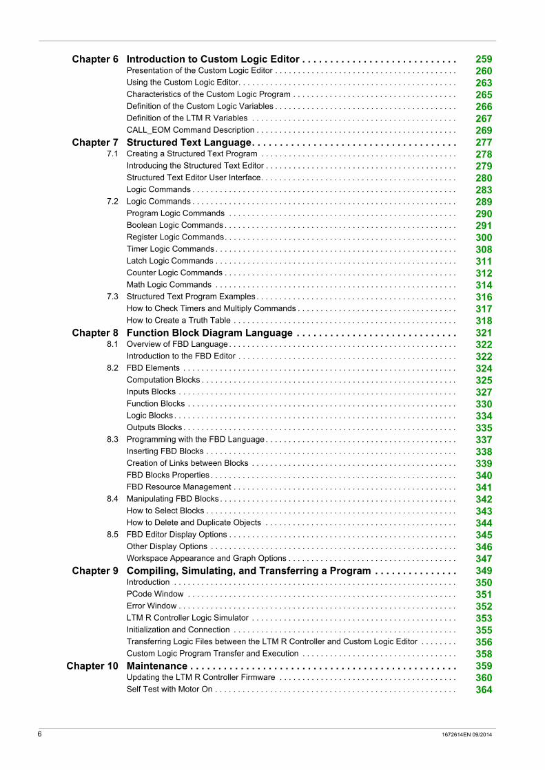
Chapter 6 Introduction to Custom Logic Editor . . . . . . . . . . . . . . . . . . . . . . . . . . . . 259Presentation of the Custom Logic Editor . . . . . . . . . . . . . . . . . . . . . . . . . . . . . . . . . . . . . . . . 260Using the Custom Logic Editor. . . . . . . . . . . . . . . . . . . . . . . . . . . . . . . . . . . . . . . . . . . . . . . . 263Characteristics of the Custom Logic Program . . . . . . . . . . . . . . . . . . . . . . . . . . . . . . . . . . . . 265Definition of the Custom Logic Variables . . . . . . . . . . . . . . . . . . . . . . . . . . . . . . . . . . . . . . . . 266Definition of the LTM R Variables . . . . . . . . . . . . . . . . . . . . . . . . . . . . . . . . . . . . . . . . . . . . . 267CALL_EOM Command Description . . . . . . . . . . . . . . . . . . . . . . . . . . . . . . . . . . . . . . . . . . . . 269
Chapter 7 Structured Text Language. . . . . . . . . . . . . . . . . . . . . . . . . . . . . . . . . . . . . 2777.1 Creating a Structured Text Program . . . . . . . . . . . . . . . . . . . . . . . . . . . . . . . . . . . . . . . . . . . 278
Introducing the Structured Text Editor . . . . . . . . . . . . . . . . . . . . . . . . . . . . . . . . . . . . . . . . . . 279Structured Text Editor User Interface. . . . . . . . . . . . . . . . . . . . . . . . . . . . . . . . . . . . . . . . . . . 280Logic Commands . . . . . . . . . . . . . . . . . . . . . . . . . . . . . . . . . . . . . . . . . . . . . . . . . . . . . . . . . . 283
7.2 Logic Commands . . . . . . . . . . . . . . . . . . . . . . . . . . . . . . . . . . . . . . . . . . . . . . . . . . . . . . . . . . 289Program Logic Commands . . . . . . . . . . . . . . . . . . . . . . . . . . . . . . . . . . . . . . . . . . . . . . . . . . 290Boolean Logic Commands . . . . . . . . . . . . . . . . . . . . . . . . . . . . . . . . . . . . . . . . . . . . . . . . . . . 291Register Logic Commands. . . . . . . . . . . . . . . . . . . . . . . . . . . . . . . . . . . . . . . . . . . . . . . . . . . 300Timer Logic Commands . . . . . . . . . . . . . . . . . . . . . . . . . . . . . . . . . . . . . . . . . . . . . . . . . . . . . 308Latch Logic Commands . . . . . . . . . . . . . . . . . . . . . . . . . . . . . . . . . . . . . . . . . . . . . . . . . . . . . 311Counter Logic Commands . . . . . . . . . . . . . . . . . . . . . . . . . . . . . . . . . . . . . . . . . . . . . . . . . . . 312Math Logic Commands . . . . . . . . . . . . . . . . . . . . . . . . . . . . . . . . . . . . . . . . . . . . . . . . . . . . . 314
7.3 Structured Text Program Examples . . . . . . . . . . . . . . . . . . . . . . . . . . . . . . . . . . . . . . . . . . . . 316How to Check Timers and Multiply Commands . . . . . . . . . . . . . . . . . . . . . . . . . . . . . . . . . . . 317How to Create a Truth Table . . . . . . . . . . . . . . . . . . . . . . . . . . . . . . . . . . . . . . . . . . . . . . . . . 318
Chapter 8 Function Block Diagram Language . . . . . . . . . . . . . . . . . . . . . . . . . . . . . 3218.1 Overview of FBD Language . . . . . . . . . . . . . . . . . . . . . . . . . . . . . . . . . . . . . . . . . . . . . . . . . . 322
Introduction to the FBD Editor . . . . . . . . . . . . . . . . . . . . . . . . . . . . . . . . . . . . . . . . . . . . . . . . 3228.2 FBD Elements . . . . . . . . . . . . . . . . . . . . . . . . . . . . . . . . . . . . . . . . . . . . . . . . . . . . . . . . . . . . 324
Computation Blocks . . . . . . . . . . . . . . . . . . . . . . . . . . . . . . . . . . . . . . . . . . . . . . . . . . . . . . . . 325Inputs Blocks . . . . . . . . . . . . . . . . . . . . . . . . . . . . . . . . . . . . . . . . . . . . . . . . . . . . . . . . . . . . . 327Function Blocks . . . . . . . . . . . . . . . . . . . . . . . . . . . . . . . . . . . . . . . . . . . . . . . . . . . . . . . . . . . 330Logic Blocks . . . . . . . . . . . . . . . . . . . . . . . . . . . . . . . . . . . . . . . . . . . . . . . . . . . . . . . . . . . . . . 334Outputs Blocks . . . . . . . . . . . . . . . . . . . . . . . . . . . . . . . . . . . . . . . . . . . . . . . . . . . . . . . . . . . . 335
8.3 Programming with the FBD Language . . . . . . . . . . . . . . . . . . . . . . . . . . . . . . . . . . . . . . . . . . 337Inserting FBD Blocks . . . . . . . . . . . . . . . . . . . . . . . . . . . . . . . . . . . . . . . . . . . . . . . . . . . . . . . 338Creation of Links between Blocks . . . . . . . . . . . . . . . . . . . . . . . . . . . . . . . . . . . . . . . . . . . . . 339FBD Blocks Properties . . . . . . . . . . . . . . . . . . . . . . . . . . . . . . . . . . . . . . . . . . . . . . . . . . . . . . 340FBD Resource Management . . . . . . . . . . . . . . . . . . . . . . . . . . . . . . . . . . . . . . . . . . . . . . . . . 341
8.4 Manipulating FBD Blocks . . . . . . . . . . . . . . . . . . . . . . . . . . . . . . . . . . . . . . . . . . . . . . . . . . . . 342How to Select Blocks . . . . . . . . . . . . . . . . . . . . . . . . . . . . . . . . . . . . . . . . . . . . . . . . . . . . . . . 343How to Delete and Duplicate Objects . . . . . . . . . . . . . . . . . . . . . . . . . . . . . . . . . . . . . . . . . . 344
8.5 FBD Editor Display Options . . . . . . . . . . . . . . . . . . . . . . . . . . . . . . . . . . . . . . . . . . . . . . . . . . 345Other Display Options . . . . . . . . . . . . . . . . . . . . . . . . . . . . . . . . . . . . . . . . . . . . . . . . . . . . . . 346Workspace Appearance and Graph Options . . . . . . . . . . . . . . . . . . . . . . . . . . . . . . . . . . . . . 347
Chapter 9 Compiling, Simulating, and Transferring a Program . . . . . . . . . . . . . . . 349Introduction . . . . . . . . . . . . . . . . . . . . . . . . . . . . . . . . . . . . . . . . . . . . . . . . . . . . . . . . . . . . . . 350PCode Window . . . . . . . . . . . . . . . . . . . . . . . . . . . . . . . . . . . . . . . . . . . . . . . . . . . . . . . . . . . 351Error Window . . . . . . . . . . . . . . . . . . . . . . . . . . . . . . . . . . . . . . . . . . . . . . . . . . . . . . . . . . . . . 352LTM R Controller Logic Simulator . . . . . . . . . . . . . . . . . . . . . . . . . . . . . . . . . . . . . . . . . . . . . 353Initialization and Connection . . . . . . . . . . . . . . . . . . . . . . . . . . . . . . . . . . . . . . . . . . . . . . . . . 355Transferring Logic Files between the LTM R Controller and Custom Logic Editor . . . . . . . . 356Custom Logic Program Transfer and Execution . . . . . . . . . . . . . . . . . . . . . . . . . . . . . . . . . . 358
Chapter 10 Maintenance . . . . . . . . . . . . . . . . . . . . . . . . . . . . . . . . . . . . . . . . . . . . . . . . 359Updating the LTM R Controller Firmware . . . . . . . . . . . . . . . . . . . . . . . . . . . . . . . . . . . . . . . 360Self Test with Motor On . . . . . . . . . . . . . . . . . . . . . . . . . . . . . . . . . . . . . . . . . . . . . . . . . . . . . 364
6 1672614EN 09/2014

Chapter 11 Connection to the LTM R Controller. . . . . . . . . . . . . . . . . . . . . . . . . . . . . 365Hardware Connection for SoMove . . . . . . . . . . . . . . . . . . . . . . . . . . . . . . . . . . . . . . . . . . . . 366Hardware Connection for the Firmware Update . . . . . . . . . . . . . . . . . . . . . . . . . . . . . . . . . . 368
Index . . . . . . . . . . . . . . . . . . . . . . . . . . . . . . . . . . . . . . . . . . . . . . . . . . . . . . 371
1672614EN 09/2014 7

8 1672614EN 09/2014

Safety Information
Important Information
NOTICE
Read these instructions carefully, and look at the equipment to become familiar with the device before trying to install, operate, or maintain it. The following special messages may appear throughout this documentation or on the equipment to warn of potential hazards or to call attention to information that clarifies or simplifies a procedure.
PLEASE NOTE
Electrical equipment should be installed, operated, serviced, and maintained only by qualified personnel. No responsibility is assumed by Schneider Electric for any consequences arising out of the use of this material.
A qualified person is one who has skills and knowledge related to the construction and operation of electrical equipment and its installation, and has received safety training to recognize and avoid the hazards involved.
BEFORE YOU BEGIN
Do not use this product on machinery lacking effective point-of-operation guarding. Lack of effective point-of-operation guarding on a machine can result in serious injury to the operator of that machine.
1672614EN 09/2014 9

This automation equipment and related software is used to control a variety of industrial processes. The type or model of automation equipment suitable for each application will vary depending on factors such as the control function required, degree of protection required, production methods, unusual conditions, government regulations, etc. In some applications, more than one processor may be required, as when backup redundancy is needed.
Only the user can be aware of all the conditions and factors present during setup, operation and maintenance of the machine; therefore, only the user can determine the automation equipment and the related safeties and interlocks which can be properly used. When selecting automation and control equipment and related software for a particular application, the user should refer to the applicable local and national standards and regulations. The Accident Prevention Manual (nationally recognized in the United States of America) also provides much useful information.
In some applications, such as packaging machinery, additional operator protection such as point-of-operation guarding must be provided. This is necessary if the operator’s hands and other parts of the body are free to enter the pinch point area and serious injury can occur. Software products cannot protect an operator from injury. For this reason the software cannot be substituted for or take the place of point-of-operation protection.
Ensure that appropriate safeties and interlocks related to point-of-operation protection have been installed and are operational before placing the equipment into service. All interlocks and safeties related to point-of-operation protection must be coordinated with the related automation equipment and software programming.
NOTE: Coordination of safeties and interlocks for point-of-operation is outside the scope of this Defined Function Block (DFB).
START UP AND TEST
Before using electrical control and automation equipment for regular operation after installation, the system should be given a start up test by qualified personnel to verify correct operation of the equipment. It is important that arrangements for such a check be made and that enough time is allowed to perform complete and satisfactory testing.
Follow all start up tests recommended in the equipment documentation. Store all equipment documentation for future references.
Software testing must be done in both simulated and real environments.
Verify that the completed system is free from all short circuits and grounds, except those grounds installed according to local regulations (according to the National Electrical Code in the U.S.A, for instance). If high-potential voltage testing is necessary, follow recommendations in equipment documentation to prevent accidental equipment damage.
Before energizing equipment: Remove tools, meters and debris from equipment. Close the equipment enclosure door. Remove ground from incoming power lines. Perform all start-up tests recommended by the manufacturer.
WARNINGUNGUARDED MACHINERY CAN CAUSE SERIOUS INJURY
Do not use this software and related automation equipment on packaging equipment which does not have point-of-operation protection.
Do not reach into machinery during operation.
Failure to follow these instructions can result in death, serious injury, or equipment damage.
CAUTIONEQUIPMENT OPERATION HAZARD
Verify that all installation and set up procedures have been completed. Before operational tests are performed, remove all blocks or other temporary holding means used for
shipment from all component devices. Remove tools, meters and debris from equipment.
Failure to follow these instructions can result in injury or equipment damage.
10 1672614EN 09/2014

OPERATION AND ADJUSTMENTS
The following precautions are from the NEMA Standards Publication ICS 7.1-1995 (English version prevails): Regardless of the care exercised in the design and manufacture of equipment or in the selection and
ratings of components, there are hazards that can be encountered if such equipment is improperly operated.
It is sometimes possible to misadjust the equipment and thus produce unsatisfactory or unsafe operation. Always use the manufacturer’s instructions as a guide for functional adjustments. Personnel who have access to these adjustments should be familiar with the equipment manufacturer’s instructions and the machinery used with the electrical equipment.
Only those operational adjustments actually required by the operator should be accessible to the operator. Access to other controls should be restricted to prevent unauthorized changes in operating characteristics.
1672614EN 09/2014 11

12 1672614EN 09/2014

About the Book
At a Glance
Document Scope
This online help describes the TeSys T DTM for TeSys T motor management system.
The purpose of this online help is to: describe the metering, monitoring, protection, and control functions of the TeSys T motor management
system. describe the custom logic editor embedded in the TeSys T DTM which allows the customization of the
control functions of the TeSys T motor management system. provide all the information necessary to implement and support a solution that meets application
requirements.
The online help describes the 4 key parts of a successful system implementation: installing the TeSys DTM library entering and setting parameters monitoring the status of the device maintaining and upgrading the TeSys T DTM library
The online help is intended for TeSys T DTM users: design engineers system integrators system operators maintenance engineers
Validity Note
This document has been updated with the release of SoMove Lite V1.9.2.0 and TeSys DTM library 2.7.6.0.
The availability of some functions depends on the LTM R controller version.
The characteristics presented in this online help should be the same as those that appear online. In line with our policy of constant improvement, we may revise content over time to improve clarity and accuracy. In the event that you see a difference between the online help and online information, use the online information as your reference.
Related Documents
You can download these technical publications and other technical information from our website at www.schneider-electric.com.
Title of Documentation Reference Number
TeSys® T LTM R Modbus Motor Management Controller - User Manual 1639501
TeSys® T LTM R Profibus DP Motor Management Controller - User Manual 1639502
TeSys® T LTM R CANopen Motor Management Controller - User Manual 1639503
TeSys® T LTM R DeviceNet Motor Management Controller - User Manual 1639504
TeSys® T LTM R Ethernet Motor Management Controller - User Manual 1639505
TeSys® T LTM CU Control Operator Unit - User Manual 1639581
TeSys® T LTM R Motor Management Controller TeSys T DTM Custom Logic Editor - User Manual
1639507
1672614EN 09/2014 13

14 1672614EN 09/2014

TeSys T DTM for FDT Container
Presentation of the TeSys T DTM
1672614EN 09/2014
Presentation of the TeSys T DTM
Chapter 1Presentation of the TeSys T DTM
What Is in This Chapter?
This chapter contains the following sections:
Section Topic Page
1.1 Introduction 16
1.2 User Interface 25
1672614EN 09/2014 15

Presentation of the TeSys T DTM
Introduction
Section 1.1Introduction
Overview
This section describes the prerequisites for using the TeSys T motor management system with SoMove and the TeSys T DTM.
What Is in This Section?
This section contains the following topics:
Topic Page
Presentation of the TeSys T Motor Management System 17
Definitions 22
Installing SoMove and the TeSys DTM Library 23
Installing Update TeSys DTM Library 24
16 1672614EN 09/2014

Presentation of the TeSys T DTM
Presentation of the TeSys T Motor Management System
Product Overview
The TeSys T motor management system offers protection, control, and monitoring capabilities for single-phase and 3-phase AC induction motors.
The system is flexible, modular, and can be configured to meet the requirements of applications in industry. The system is designed to meet the needs of integrated protections systems with open communications and a global architecture.
Highly accurate sensors and solid-state full motor protection provide better utilization of the motor. Complete monitoring functions enable analysis of motor operating conditions and faster responses to prevent system downtime.
The system offers diagnostic and statistics functions and configurable warnings and faults, allowing better predictive maintenance of components, and provides data to continuously improve the entire system.
Examples of Supported Machine Segments
The motor management system supports the following machine segments:
Machine Segment Examples
Process and special machine segments Water and waste water treatment water treatment (blowers and agitators)
Metal, minerals, and mining cement glass steel ore extraction
Oil and gas oil and gas processing petrochemical refineries, offshore platforms
MicroelectronicPharmaceuticalChemical industry cosmetics detergents fertilizers paint
Transportation industry automotive transfer lines airports
Other industries tunnel machines cranes
Complex machine segments Includes highly automated or coordinated machines used in: pumping systems paper conversion printing lines HVAC
1672614EN 09/2014 17
Presentation of the TeSys T DTM
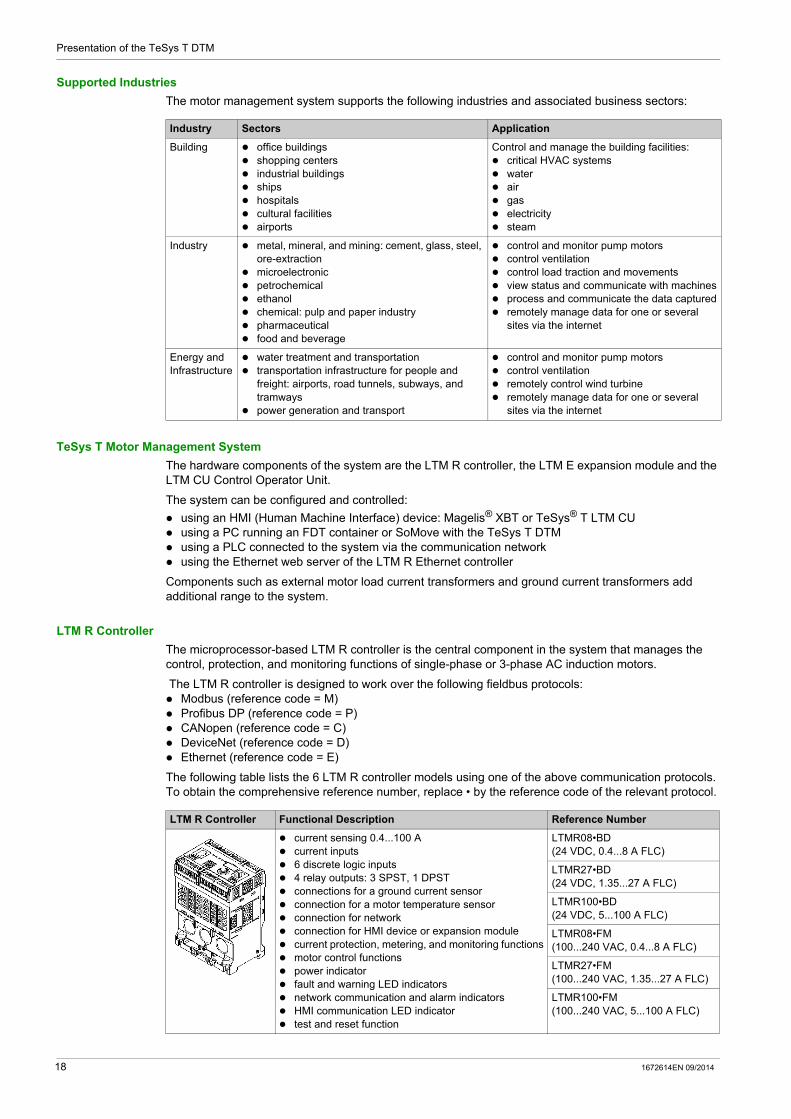
Supported Industries
The motor management system supports the following industries and associated business sectors:
TeSys T Motor Management System
The hardware components of the system are the LTM R controller, the LTM E expansion module and the LTM CU Control Operator Unit.
The system can be configured and controlled:
using an HMI (Human Machine Interface) device: Magelis® XBT or TeSys® T LTM CU using a PC running an FDT container or SoMove with the TeSys T DTM using a PLC connected to the system via the communication network using the Ethernet web server of the LTM R Ethernet controller
Components such as external motor load current transformers and ground current transformers add additional range to the system.
LTM R Controller
The microprocessor-based LTM R controller is the central component in the system that manages the control, protection, and monitoring functions of single-phase or 3-phase AC induction motors.
The LTM R controller is designed to work over the following fieldbus protocols: Modbus (reference code = M) Profibus DP (reference code = P) CANopen (reference code = C) DeviceNet (reference code = D) Ethernet (reference code = E)
The following table lists the 6 LTM R controller models using one of the above communication protocols. To obtain the comprehensive reference number, replace • by the reference code of the relevant protocol.
Industry Sectors Application
Building office buildings shopping centers industrial buildings ships hospitals cultural facilities airports
Control and manage the building facilities: critical HVAC systems water air gas electricity steam
Industry metal, mineral, and mining: cement, glass, steel, ore-extraction
microelectronic petrochemical ethanol chemical: pulp and paper industry pharmaceutical food and beverage
control and monitor pump motors control ventilation control load traction and movements view status and communicate with machines process and communicate the data captured remotely manage data for one or several
sites via the internet
Energy and Infrastructure
water treatment and transportation transportation infrastructure for people and
freight: airports, road tunnels, subways, and tramways
power generation and transport
control and monitor pump motors control ventilation remotely control wind turbine remotely manage data for one or several
sites via the internet
LTM R Controller Functional Description Reference Number
current sensing 0.4...100 A current inputs 6 discrete logic inputs 4 relay outputs: 3 SPST, 1 DPST connections for a ground current sensor connection for a motor temperature sensor connection for network connection for HMI device or expansion module current protection, metering, and monitoring functions motor control functions power indicator fault and warning LED indicators network communication and alarm indicators HMI communication LED indicator test and reset function
LTMR08•BD (24 VDC, 0.4...8 A FLC)
LTMR27•BD (24 VDC, 1.35...27 A FLC)
LTMR100•BD (24 VDC, 5...100 A FLC)
LTMR08•FM (100...240 VAC, 0.4...8 A FLC)
LTMR27•FM (100...240 VAC, 1.35...27 A FLC)
LTMR100•FM (100...240 VAC, 5...100 A FLC)
18 1672614EN 09/2014

Presentation of the TeSys T DTM
LTM E Expansion Module
There are 2 models of LTM E expansion modules that provide voltage monitoring functionality and 4 additional logic inputs. The LTM E expansion modules are powered by the LTM R controller via a connector cable.
HMI Device: Magelis XBTN410
The system uses the Magelis® XBTN410 HMI device with a liquid crystal display.
HMI Device: LTM CU Control Operator Unit
The system uses the TeSys® T LTM CU Control Operator Unit HMI device with a liquid crystal display and contextual navigation keys. The LTM CU is internally powered by the LTM R. Refer to the TeSys T LTM CU Control Operator Unit User Manual for more information.
LTM E Expansion Module Functional Description Reference Number
voltage sensing 110...690 VAC 3 voltage inputs 4 additional discrete logic inputs additional voltage protection, metering, and monitoring
functions power LED indicator logic input status LED indicators
Additional components required for an optional expansion module: LTM R controller to LTM E connection cable
LTMEV40BD (24 VDC logic inputs)
LTMEV40FM (100...240 VAC logic inputs)
Magelis® XBTN410 Functional Description Reference Number
system configuration through menu entries display of parameters, warnings, and faults
Additional components required for an optional HMI device: separate power source LTM R / LTM E to HMI communication cable Magelis XBTL1000 programming software
XBTN410 (HMI)
XBTZ938 (cable)
XBTL1000 (software)
LTM CU Control Operator Unit Functional Description Reference Number
system configuration through menu entries display of parameters, warnings, and faults motor control
Additional components required for an optional HMI device: LTM R / LTM E to HMI communication cable
LTM CU
LTM9CU•0(HMI communication cable)
LTM9KCUkit for portable LTM CU
1672614EN 09/2014 19

Presentation of the TeSys T DTM
SoMove with the TeSys T DTM
SoMove software is a Microsoft® Windows®-based application, using the open FDT/DTM technology.
SoMove contains many DTMs. A specific DTM exists for the TeSys T motor management system.
Load Current Transformers
External load current transformers expand the current range for use with motors greater than 100 full load Amperes.
The lug-lug kit provides bus bars and lug terminals that adapt the pass through wiring windows and provide line and load terminations for the power circuit.
SoMove with the TeSys T DTM
Functional Description Reference Number
system configuration through menu entries display of parameters, warnings, and faults motor control customization of operating modes
Additional components required for the SoMove FDT container: a PC separate power source LTM R / LTM E / LTM CU to PC communication cables
SoMove with the TeSys T DTM
TCSMCNAM3M002P (cable kit)SoMoveTM
Schneider Electric Load Current Transformers
Primary Secondary Inside Diameter Reference Number
mm in.
100 1 35 1.38 LT6CT1001
200 1 35 1.38 LT6CT2001
400 1 35 1.38 LT6CT4001
800 1 35 1.38 LT6CT8001
NOTE: The following load current transformers are also available: Schneider Electric LUTC0301, LUTC0501, LUTC1001, LUTC2001, LUTC4001, and LUTC8001.
Square D Lug-lug Kit Description Reference Number
Square D Lug-lug Kit MLPL9999
20 1672614EN 09/2014

Presentation of the TeSys T DTM
Ground Current Transformers
External ground current transformers measure ground fault conditions.
Schneider Electric Vigirex Ground Current Transformers
Type Maximum Current
Inside Diameter Transformation Ratio
Reference Numbermm in.
TA30 65 A 30 1.18 1000:1 50437
PA50 85 A 50 1.97 50438
IA80 160 A 80 3.15 50439
MA120 250 A 120 4.72 50440
SA200 400 A 200 7.87 50441
PA300 630 A 300 11.81 50442
POA 85 A 46 1.81 50485
GOA 250 A 110 4.33 50486
1672614EN 09/2014 21
Presentation of the TeSys T DTM
Definitions
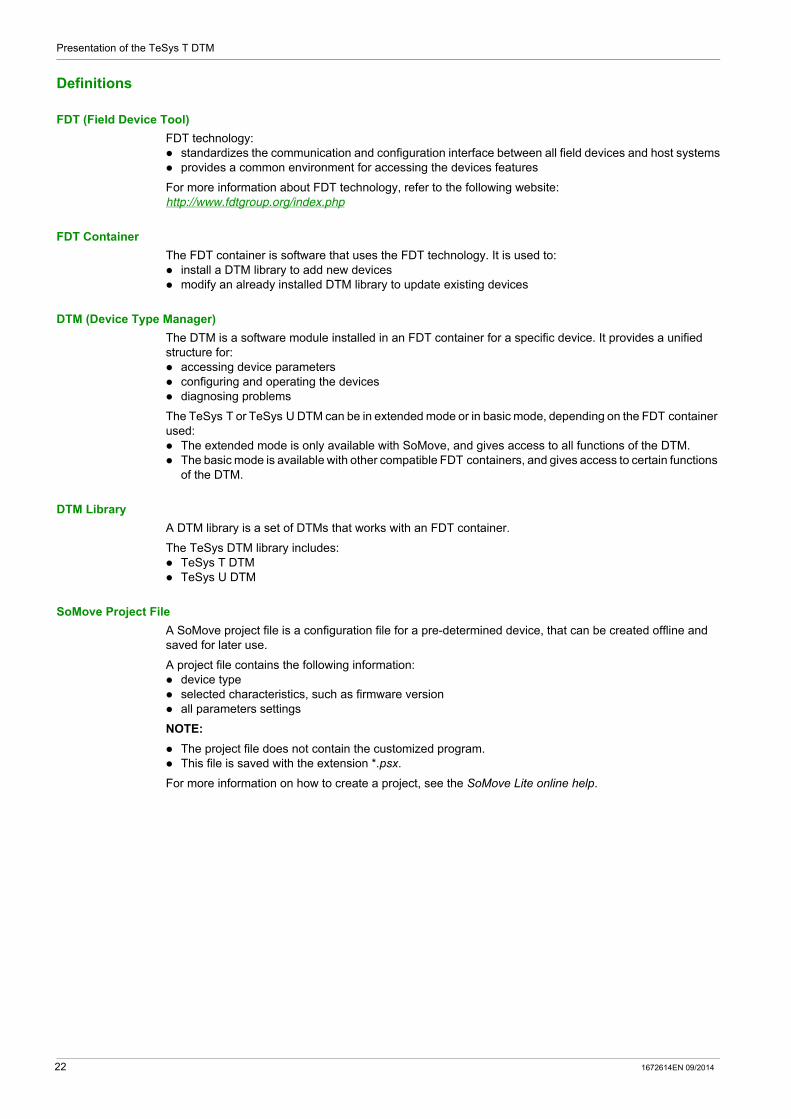
FDT (Field Device Tool)
FDT technology: standardizes the communication and configuration interface between all field devices and host systems provides a common environment for accessing the devices features
For more information about FDT technology, refer to the following website: http://www.fdtgroup.org/index.php
FDT Container
The FDT container is software that uses the FDT technology. It is used to: install a DTM library to add new devices modify an already installed DTM library to update existing devices
DTM (Device Type Manager)
The DTM is a software module installed in an FDT container for a specific device. It provides a unified structure for: accessing device parameters configuring and operating the devices diagnosing problems
The TeSys T or TeSys U DTM can be in extended mode or in basic mode, depending on the FDT container used: The extended mode is only available with SoMove, and gives access to all functions of the DTM. The basic mode is available with other compatible FDT containers, and gives access to certain functions
of the DTM.
DTM Library
A DTM library is a set of DTMs that works with an FDT container.
The TeSys DTM library includes: TeSys T DTM TeSys U DTM
SoMove Project File
A SoMove project file is a configuration file for a pre-determined device, that can be created offline and saved for later use.
A project file contains the following information: device type selected characteristics, such as firmware version all parameters settings
NOTE:
The project file does not contain the customized program. This file is saved with the extension *.psx.
For more information on how to create a project, see the SoMove Lite online help.
22 1672614EN 09/2014

Presentation of the TeSys T DTM
Installing SoMove and the TeSys DTM Library
Overview
The installation of SoMove includes some DTMs such as the TeSys DTM library.
The TeSys DTM library includes: TeSys T DTM TeSys U DTM
These DTM are automatically installed during the SoMove installation process.
Downloading SoMove
SoMove can be downloaded from the Schneider Electric website (www.schneider-electric.com) by entering SoMove Lite in the Search field.
Installing SoMove
Step Action
1 Unzip the downloaded file: the SoMove file is unzipped in a folder named SoMove_Lite - V.X.X.X.X (where X.X.X.X is the version number). Open this folder and double-click setup.exe.
2 In the Choose Setup Language dialog box, select the installation language.
3 Click OK.
4 In the Welcome to the Installation Wizard for SoMove Lite dialog box, click the Next button.
5 If an Install Shield Wizard dialog box appears and informs you that you must install Modbus driver, click the Install button. Result: Modbus driver is installed automatically.
6 In the Readme and Release Notes dialog box, click the Next button.
7 In the Readme dialog box, click the Next button.
8 In the License Agreement dialog box: Read carefully the license agreement. Select I accept the terms in the license agreement option. Click the Next button.
9 In the Customer Information dialog box: Enter the following information in the corresponding fields: First name Last name Company name
Select an installation option: Either the Anyone who uses this computer option if SoMove Lite is used by all users of this
computer, or Only for me if SoMove Lite is used only by you.
Click the Next button.
10 In the Destination Folder dialog box: If necessary, modify the SoMove Lite destination folder by clicking the Change button. Click the Next button.
11 In the Shortcuts dialog box: If you want to create a shortcut on the desktop and/or in the quick launch bar, select the
corresponding options. Click the Next button.
12 In the Ready to Install the Program dialog box, click the Install button.Result: The SoMove Lite components are installed automatically: Modbus communication DTM library which contains the communication protocol DTM libraries which contain different drive catalogs SoMove Lite itself
13 In the Installation Wizard Completed dialog box, click the Finish button.Result: SoMove Lite is installed on your computer.
1672614EN 09/2014 23
Presentation of the TeSys T DTM
Installing Update TeSys DTM Library
Overview
The TeSys DTM library includes: TeSys T DTM TeSys U DTM
These DTM are automatically installed during the SoMove installation process.
Downloading TeSysDTMLibrary
TeSysDTMLibrary can be downloaded from the Schneider Electric website (www.schneider-electric.com) by entering TeSysDTMLibrary in the Search field.
Installing Update TeSys DTM Library
Step Action
1 Unzip the downloaded file. Open this folder and double-click setup.exe. The TeSysDTMLibrary file is unzipped in a folder named TeSysDTMLibrary - V.X.X.X.X (where X.X.X.X is the version number).
2 In the Choose Setup Language dialog box, select the installation language.
3 Click OK.
4 In the Welcome to the Installation Wizard for TeSysDTMLibrary dialog box, click the Next button.
5 In the Readme and Release Notes dialog box, click the Next button.
6 In the License Agreement dialog box: Read carefully the license agreement. Select I accept the terms in the license agreement option. Click the Next button.
7 In the Customer Information dialog box: Enter the following information in the corresponding fields: First name Last name Company name
Select an installation option: Either the Anyone who uses this computer option if TeSys DTM library is used by all users
of this computer, or Only for me if TeSys DTM library is used only by you.
Click the Next button.
8 In the Destination Folder dialog box: If necessary, modify the TeSys DTM library destination folder by clicking the Change button. Click the Next button.
9 In the Setup Type dialog box: Select the setup type: recommended Typical. Click the Next button.
10 In the Ready to Install the Program dialog box, click the Install button.Result: The TeSys DTM library components are installed automatically.
11 In the Installation Wizard Completed dialog box, click the Finish button.Result: The TeSys DTM library is installed on your computer.
24 1672614EN 09/2014
Presentation of the TeSys T DTM
User Interface
Section 1.2User Interface
Overview
This section describes the different menus and tabs available in SoMove with the TeSys T DTM.
What Is in This Section?
This section contains the following topics:
Topic Page
General Description 26
Menu Bar and Tool Bar 28
Command Submenu 31
Password Management 32
Device Version Management 33
Status Bar and Synchronization Data Bar 34
my Device Tab 36
operate Tab 37
Tab Zone 39
parameter list Tab 42
fault Tab 44
monitoring Tab 45
diagnostic Tab 47
1672614EN 09/2014 25
Presentation of the TeSys T DTM
General Description
Overview
The TeSys T DTM can be in extended mode or in basic mode, depending on the FDT container used: The extended mode is only available with SoMove, and gives access to all functions of the DTM. The basic mode is available with other compatible FDT containers, and gives access to certain functions
of the DTM.
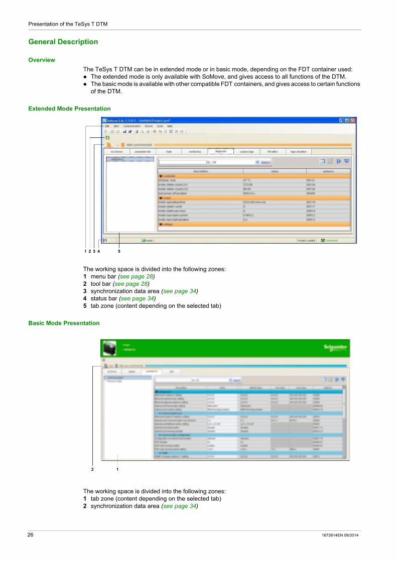
Extended Mode Presentation
The working space is divided into the following zones:1 menu bar (see page 28)2 tool bar (see page 28)3 synchronization data area (see page 34)4 status bar (see page 34)5 tab zone (content depending on the selected tab)
Basic Mode Presentation
The working space is divided into the following zones:1 tab zone (content depending on the selected tab)2 synchronization data area (see page 34)
26 1672614EN 09/2014
Presentation of the TeSys T DTM
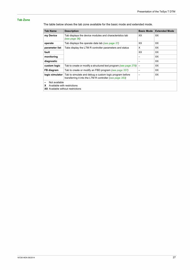
Tab Zone
The table below shows the tab zone available for the basic mode and extended mode.
Tab Name Description Basic Mode Extended Mode
my Device Tab displays the device modules and characteristics tab (see page 36)
XX XX
operate Tab displays the operate data tab (see page 37) XX XX
parameter list Tabs display the LTM R controller parameters and status X XX
fault XX XX
monitoring – XX
diagnostic – XX
custom logic Tab to create or modify a structured text program (see page 278) – XX
FB diagram Tab to create or modify an FBD program (see page 337) – XX
logic simulator Tab to simulate and debug a custom logic program before transferring it into the LTM R controller (see page 353)
– XX
– Not availableX Available with restrictionsXX Available without restrictions
1672614EN 09/2014 27
Presentation of the TeSys T DTM
Menu Bar and Tool Bar
Menu Bar
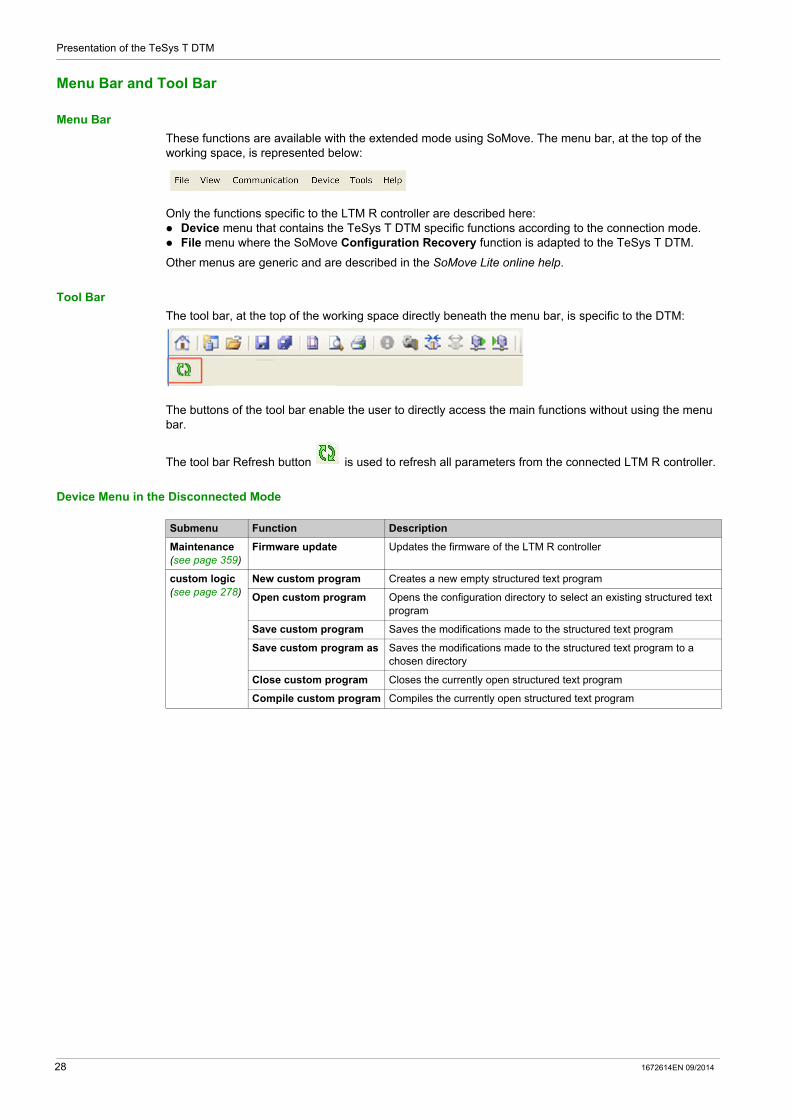
These functions are available with the extended mode using SoMove. The menu bar, at the top of the working space, is represented below:
Only the functions specific to the LTM R controller are described here: Device menu that contains the TeSys T DTM specific functions according to the connection mode. File menu where the SoMove Configuration Recovery function is adapted to the TeSys T DTM.
Other menus are generic and are described in the SoMove Lite online help.
Tool Bar
The tool bar, at the top of the working space directly beneath the menu bar, is specific to the DTM:
The buttons of the tool bar enable the user to directly access the main functions without using the menu bar.
The tool bar Refresh button is used to refresh all parameters from the connected LTM R controller.
Device Menu in the Disconnected Mode
Submenu Function Description
Maintenance (see page 359)
Firmware update Updates the firmware of the LTM R controller
custom logic (see page 278)
New custom program Creates a new empty structured text program
Open custom program Opens the configuration directory to select an existing structured text program
Save custom program Saves the modifications made to the structured text program
Save custom program as Saves the modifications made to the structured text program to a chosen directory
Close custom program Closes the currently open structured text program
Compile custom program Compiles the currently open structured text program
28 1672614EN 09/2014

Presentation of the TeSys T DTM
Device Menu in the Connected Mode
FB diagram (see page 321)
New FB diagram Creates a new empty FBD program
Open FB diagram Opens the configuration directory to select an existing FBD program
Save FB diagram Saves the modifications made to the FBD program
Save FB diagram as Saves the modifications made to the FBD program to a chosen directory
Compile FB diagram to ST program
Transforms the currently open FBD program to a structured text file
FBD editor Allows users to manipulate FBD blocks (Copy, Cut, Paste, Delete, Select all, and Unselect)
View\Show grid Displays the grid lines
View\Hide grid Hides the grid lines
View\Properties windows Displays the properties of the selected object
View\Toolbox Displays the different categories of blocks
View\Zoom out Displays more of the program
View\Zoom in Displays the program in more detail
View\Zoom to Displays a customized view of the program (zooms to 50%, 75%, 100%, 150%, 200%, or 400%)
Tools\Renumber links Sorts link numbers in ascending order
Tools\Show all links Displays which blocks are linked together
Tools\Hide all links Provides a better overall view of the blocks
Tools\Renumber Function Blocks
Sorts block numbers in ascending order
Submenu Function Description
Submenu Function Description
File transfer (see page 246)
backup command Specific function of the LTM R Ethernet controller that copies the operating parameter file in the controller to the server
restore command Specific function of the LTM R Ethernet controller that copies the operating parameter file on the server to the controller
Command (see page 31)
run1 Activates the function associated to the output O.1
run2 Activates the function associated to the output O.2
stop De-activates outputs
loc/rem Switches between local and remote control mode
enter configuration Allows modification of main parameters in the connected mode
exit configuration Exits the previous state.
Reset (see page 206)
fault reset Resets detected faults
password (see page 32)
create password Creates a new password
modify password Modifies the password
delete password Deletes the password
Maintenance Set Device Date & Time Synchronizes the date and time of the LTM R controller with the date and time of the PC
test (see page 364) Simulates a thermal fault
1672614EN 09/2014 29
Presentation of the TeSys T DTM
Configuration Recovery
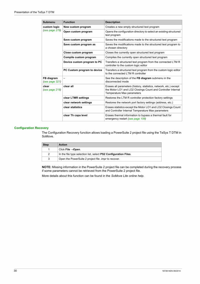
The Configuration Recovery function allows loading a PowerSuite 2 project file using the TeSys T DTM in SoMove.
NOTE: Missing information in the PowerSuite 2 project file can be completed during the recovery process if some parameters cannot be retrieved from the PowerSuite 2 project file.
More details about this function can be found in the SoMove Lite online help.
custom logic (see page 278)
New custom program Creates a new empty structured text program
Open custom program Opens the configuration directory to select an existing structured text program
Save custom program Saves the modifications made to the structured text program
Save custom program as Saves the modifications made to the structured text program to a chosen directory
Close custom program Closes the currently open structured text program
Compile custom program Compiles the currently open structured text program
Device custom program to PC Transfers a structured text program from the connected LTM R controller to the custom logic editor
PC Custom program to device Transfers a structured text program from the custom logic editor to the connected LTM R controller
FB diagram (see page 321)
– See the description of the FB diagram submenu in the disconnected mode
clear (see page 218)
clear all Erases all parameters (history, statistics, network, etc.) except the Motor LO1 and LO2 Closings Count and Controller Internal Temperature Max parameters
clear LTMR settings Restores the LTM R controller protection factory settings
clear network settings Restores the network port factory settings (address, etc.)
clear statistics Erases statistics except the Motor LO1 and LO2 Closings Count and Controller Internal Temperature Max parameters
clear Th capa level Erases thermal information to bypass a thermal fault for emergency restart (see page 108)
Submenu Function Description
Step Action
1 Click File → Open.
2 In the file type selection list, select PS2 Configuration Files.
3 Open the PowerSuite 2 project file .impr to recover.
30 1672614EN 09/2014

Presentation of the TeSys T DTM
Command Submenu
Overview
This function is available with the extended mode using SoMove. The command submenu functions allow to: control the LTM R controller logic outputs choose between local and remote mode enter the configuration mode
Output Control Functions
Control functions run1, run2, and stop are used to control LTM R controller outputs O.1 and O.2.
The result of these functions depends on the following parameters: the motor operating mode the device status the control mode the channel setting
The following table lists the functions for each operating mode: (see page 184)
Local and Remote Control Function
The loc/rem control function is used to switch between the local and remote control modes.
This function does not depend on the operating mode.
Configuration Mode
In the disconnected mode, the main parameters can be modified at any time.
In the connected mode, the enter configuration command allows entering the configuration mode to: set the main parameters of the LTM R controller, upload custom logic files.
The exit configuration command exits the configuration mode.
NOTE: If an incorrect parameter is set, the device ignores the exit configuration command and remains in the configuration mode. The LTM R configuration fault bit is set (see page 76).
Operating Mode Assignment run1 run2 stop
Overload 2-wire (maintained) No action No action No action
3-wire (impulse)
Independent 2-wire (maintained) Control motor (O.1) Control O.2 Stop motor (open O.1) and open O.2 while pressed
3-wire (impulse) Start motor (close O.1) Close O.2 Stop motor (open O.1) and open O.2
Reverser 2-wire (maintained) Forward run Reverse run Stop while pressed
3-wire (impulse) Start motor forward Start motor reverse Stop motor
Two-step 2-wire (maintained) Control motor No action Stop while pressed
3-wire (impulse) Start motor No action Stop motor
Two-speed 2-wire (maintained) Low speed control High speed control Stop while pressed
3-wire (impulse) Low speed start High speed start Stop motor
WARNINGUNINTENDED EQUIPMENT OPERATION
The motor is forced to stop when activating the configuration mode. Consider the effect on all connected equipment before performing any operations. Never assume that the motor is in a certain motor state before commanding a change of state. Always positively confirm the motor state before acting on a motor.
Failure to follow these instructions can result in death, serious injury, or equipment damage.
1672614EN 09/2014 31
Presentation of the TeSys T DTM
Password Management
Overview
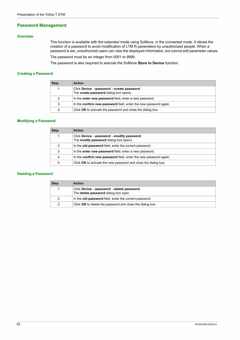
This function is available with the extended mode using SoMove, in the connected mode. It allows the creation of a password to avoid modification of LTM R parameters by unauthorized people. When a password is set, unauthorized users can view the displayed information, but cannot edit parameter values.
The password must be an integer from 0001 to 9999.
The password is also required to execute the SoMove Store to Device function.
Creating a Password
Modifying a Password
Deleting a Password
Step Action
1 Click Device → password → create password.The create password dialog box opens.
2 In the enter new password field, enter a new password.
3 In the confirm new password field, enter the new password again.
4 Click OK to activate the password and close the dialog box.
Step Action
1 Click Device → password → modify password.The modify password dialog box opens.
2 In the old password field, enter the current password.
3 In the enter new password field, enter a new password.
4 In the confirm new password field, enter the new password again.
5 Click OK to activate the new password and close the dialog box.
Step Action
1 Click Device → password → delete password.The delete password dialog box open.
2 In the old password field, enter the current password.
3 Click OK to delete the password and close the dialog box.
32 1672614EN 09/2014

Presentation of the TeSys T DTM
Device Version Management
Overview
This function is available with the basic mode or with the extended mode using SoMove.
A project is created for a specific firmware version of the LTM R controller and the LTM E expansion module.
A project can be stored to a TeSys T device only when its firmware version is the same as the firmware version set in the project.
If it is not the case, the firmware version set in the project must be modified, and the content of the project must be converted to match the firmware version of the TeSys T device.
Edit Topology Window
This procedure describes how to modify the device firmware in the project:
NOTE: If the firmware versions do not match when doing a Store to device command, the Edit topology window opens with the connected device firmware version selected.
Configuration Conversion Window
After converting the firmware devices and the content of the project, the Configuration conversion window provides which parameters were updated in the application.
There are 3 possible effects on parameters after converting the project: A parameter was removed. A parameter was added, the factory setting of the parameter is automatically selected. A parameter was modified to the factory setting. This happens when the parameter exceeds the
minimum or maximum value of the parameter.
NOTE: Always check the parameters which were modified by the convertion in order to match your application needs.
If a parameter is modified and it is not available on the basic mode, it is necessary to use the extended mode with SoMove to modify it.
Step Action
1 Select the my Device tab.
2 Click the Modify button.
3 Change the firmware version of the project to match the firmware version of your LTM R controller and/or the LTM E expansion module.
4 Click the Convert button.
1672614EN 09/2014 33

Presentation of the TeSys T DTM
Status Bar and Synchronization Data Bar
Objective
The synchronization data bar, above the working space, displays the synchronization status of the data between the LTM R controller and the PC.
The status bar, at the bottom of the working space, displays the current status of the LTM R controller and information related to SoMove. For more information on the status bar icon for SoMove, see the SoMove Lite online help.
Extended Mode Description
1 LTM R controller status2 Project status3 Connection status4 Synchronization data bar
Basic Mode Description
1 Connection status2 Synchronization data bar
34 1672614EN 09/2014

Presentation of the TeSys T DTM
LTM R Controller Status
This bar is available with the basic mode or with the extended mode using SoMove.
The TeSys T DTM displays the status of the LTM R controller. The status is available only in the connected mode.
The LTM R controller status can be one of the following: in config.: The LTM R controller is in the configuration mode (see page 31). trip: The LTM R controller is in tripped state. fault: A fault is detected by the LTM R controller. Details of the detected fault are available in the fault
tab (see page 44). running: The LTM R controller detects that the motor is running. starting: The motor controlled by the LTM R controller is starting up. warning: A warning is detected by the LTM R controller. Details of the detected warning are available
in the fault tab (see page 44). ready: No fault is detected by the LTM R controller. Not ready: The LTM R controller is in a temporary intermediate state.
Project Status
This bar is available only with the extended mode using SoMove.
The status of the SoMove project can be: Project Loaded: A project is displayed in the working space. No Project Open: The project working space is empty.
For more information, see the section about working in the disconnected mode in the SoMove Lite online help.
Connection Status
This bar is available with the basic mode or with the extended mode using SoMove.
The connection status indicates the connection mode between the LTM R controller and the PC:
Synchronization Data Area
This bar is available with the basic mode or with the extended mode using SoMove.
When the LTM R controller is in the connected mode, displayed data is automatically synchronized.
The synchronization data area indicates the synchronization status of the parameters between the LTM R controller and the PC:
Disconnected Mode Disturbed Mode Connected Mode
Icon
Description The LTM R controller is not connected to the PC.
The connection between the LTM R controller and the PC is disturbed or lost.
The LTM R controller is connected to the PC.
Disconnected Mode Connected Mode
Icon
Description The LTM R controller is not synchronized with the PC: Parameters list headers and synchronization
data area are blue. Parameters are not read in real time from the
LTM R controller. All settings can be modified as in configuration
mode. Modified parameters are written locally in the
SoMove project on PC. The project should be saved to store these modifications.
The LTM R controller is synchronized with the PC: Parameters list headers and synchronization
data area are orange. Parameters displayed are read in real time
from the LTM R controller. Some main settings can be modified only in
configuration mode (see page 31). Modified parameters are written in real time to
the LTM R controller without requiring confirmation.
1672614EN 09/2014 35

Presentation of the TeSys T DTM
my Device Tab
Overview
This tab is available with the basic mode or with the extended mode using SoMove.
The my Device tab displays the main characteristics and modules of the selected LTM R controller.
Description
This figure presents the informations about the TeSys T motor management system.
Information Displayed
The my Device tab displays the following information about the TeSys T motor management system: characteristics: current rating in Amperes control voltage: LTM R controller power supply in Volts network port protocol presence of voltage measurement number of logic inputs/outputs from the expansion module
structure of the TeSys T motor management system: reference number of each module firmware version of each module Modify button to convert the current project firmware to match the connected product firmware
(see page 33)
software: version of the TeSys T DTM
visual elements: A picture represents the LTM R controller corresponding to the selected type.
36 1672614EN 09/2014

Presentation of the TeSys T DTM
operate Tab
Overview
This tab is available with the basic mode or with the extended mode using SoMove.
The operate tab is used to set and display the LTM R controller operating data.
Description
The working space is divided in 3 zones: Monitoring: to list of parameters to observe in operate tab Input / Output Terminals: to simulate the activity on an Input / Output Settings: to change parameters online
1 Monitoring area2 Input / Output Terminals area3 Settings area
Monitoring Parameters
Add a parameter in the Monitoring area:
To remove a parameter from the Monitoring area, click the button in front of the parameter to remove.
Input / Output Terminals Status
The table below shows the status of the input/output of the LTM R controller.
Step Action
1
Click the button.
2 Select the parameter to add in Monitoring.
3 Click the ADD button.The parameter is displayed in the Monitoring area.
Status Input/Output Color Status Box Descriptive Text
Active Green Active
Inactive Grey Inactive
1672614EN 09/2014 37

Presentation of the TeSys T DTM
Settings Parameters
Add a parameter in the Settings area:
To remove a parameter from the Settings area, click the button in front of the parameter to remove.
Step Action
1
Click the button.
2 Select the parameter to add in the Settings area.
3 Click the ADD button.The parameter is displayed in the Settings area.
38 1672614EN 09/2014

Presentation of the TeSys T DTM
Tab Zone
Overview
The following tabs display information in the same way.
Description
This figure presents the common information in these tabs:
1 Tree view with items and subitems used to access to different tables of parameters.
2 Display area with the table of parameters.
3 Search function.
4 Display area tool bar.
Tree View
The tree view is composed of items with or without subitems. Select an item or subitem in the tree to update the display area on the right. The displayed table includes the corresponding parameters grouped in families and subfamilies.
Tab Name Description Basic Mode Extended Mode
parameter list Tabs display the LTM R controller parameters and status
X XX
fault XX XX
monitoring – XX
diagnostic – XX
This topic presents the different parts of the screen and their function.
– Not availableX Available with restrictionsXX Available without restrictions
1672614EN 09/2014 39

Presentation of the TeSys T DTM
Display Area Tool Bar
The view of the display area can be modified using the following buttons available on the top right corner of the display area:
Display Area in Grid View
1 Column header.
2 Parameter family.
3 Parameter subfamily.
4 Parameters: There is one line per parameter with some of its properties displayed in the different cells of the line. Content of white cells can be modified, gray cells are read-only.
5 Collapse/Expand icon: to collapse or expand a parameter family or subfamily, click the arrow of the corresponding colored line.
Sorting Parameters
To sort the parameters according to the values in a column:
Button Function Description
Grid view Parameters are listed by family and subfamily in a table.
Sketch view Parameters are presented with diagrams (charts, drawings, etc.) to explain parameters settings in a user-friendly way. Currently, TeSys T DTM does not provide such a view.
Expand All Expand all families and subfamilies to display all parameters.
Collapse All Collapse all families and subfamilies in the display area.
Step Action Result Header Example
1 Click a first time on the header.
Parameters are sorted in ascending order of the values column (alphabetically or numerically) in their respective subfamily and family.
Header appears with an arrow pointing upwards.
2 Click a second time on the header.
Parameters are sorted in descending order of the values in the column (alphabetically or numerically) in their respective subfamily and family.
Header appears with an arrow pointing downwards.
3 Click a third time on the header.
Parameters are displayed in their initial order. Header appears according to its initial representation.
40 1672614EN 09/2014

Presentation of the TeSys T DTM
Modifying the Order of Columns
To modify the order of columns in the display:
Search Function
To find a specific text in a displayed table:
Step Action
1 Click the header of the column.
2 Drag the column to the correct location.
Step Action
1 In the first field of the search bar at the top of the display area, enter the characters to search for (part of word, code, unit, etc.).
2 Select the column to search from the list.If you select the All option, the search is performed in all columns of the table.
3 Click Search: The first matching text found is highlighted. To search for other instances, click again the Search button. If no matching text is found, the color of characters in the search field becomes red.
1672614EN 09/2014 41

Presentation of the TeSys T DTM
parameter list Tab
Overview
This tab is available with the basic mode but with restrictions or with the extended mode using SoMove.
The parameter list tab is used to set and display the LTM R controller setting parameters.
Only parameter values in the white entry fields can be modified.
Description
For a global description of the tab, refer to the tab zone description (see page 39).
1 Parameter value column.2 Modification column: a pen appears if the corresponding value is different from its factory settings.3 Modifiable parameter factory settings column.4 Numerical parameter minimum value column.5 Numerical parameter maximum value column.6 Address column: displays the parameter register and bit number when relevant.
Setting Numerical Values
There are 2 ways to set a parameter with a numerical value: direct entry of the numerical value value selection using the spin buttons
To set a numerical value by direct entry:
Step Action
1 Select an item from the tree view.
2 Type the parameter value in the white entry field.
3 Press ENTER to validate the new parameter value entry: If the value is between the minimum and maximum values and consistent with the resolution interval, the
parameter value is set to the new value. If the value is between the minimum and maximum values but not consistent with the resolution interval,
the parameter value is rounded up to an authorized value. If the value is not between the minimum and maximum values: If the value requested is below the minimum value, the parameter value is set to the minimum value. If the value requested is above the maximum value, the parameter value is set to the maximum value.
42 1672614EN 09/2014
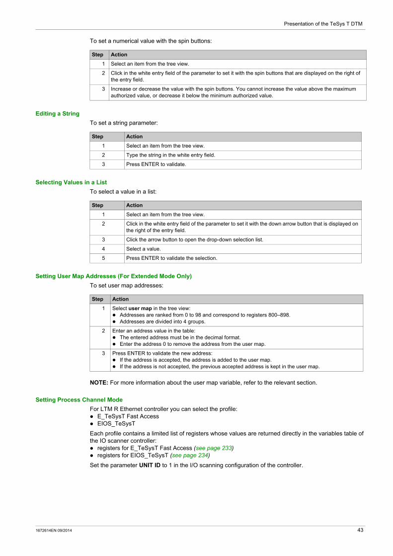
Presentation of the TeSys T DTM
To set a numerical value with the spin buttons:
Editing a String
To set a string parameter:
Selecting Values in a List
To select a value in a list:
Setting User Map Addresses (For Extended Mode Only)
To set user map addresses:
NOTE: For more information about the user map variable, refer to the relevant section.
Setting Process Channel Mode
For LTM R Ethernet controller you can select the profile: E_TeSysT Fast Access EIOS_TeSysT
Each profile contains a limited list of registers whose values are returned directly in the variables table of the IO scanner controller: registers for E_TeSysT Fast Access (see page 233) registers for EIOS_TeSysT (see page 234)
Set the parameter UNIT ID to 1 in the I/O scanning configuration of the controller.
Step Action
1 Select an item from the tree view.
2 Click in the white entry field of the parameter to set it with the spin buttons that are displayed on the right of the entry field.
3 Increase or decrease the value with the spin buttons. You cannot increase the value above the maximum authorized value, or decrease it below the minimum authorized value.
Step Action
1 Select an item from the tree view.
2 Type the string in the white entry field.
3 Press ENTER to validate.
Step Action
1 Select an item from the tree view.
2 Click in the white entry field of the parameter to set it with the down arrow button that is displayed on the right of the entry field.
3 Click the arrow button to open the drop-down selection list.
4 Select a value.
5 Press ENTER to validate the selection.
Step Action
1 Select user map in the tree view: Addresses are ranked from 0 to 98 and correspond to registers 800–898. Addresses are divided into 4 groups.
2 Enter an address value in the table: The entered address must be in the decimal format. Enter the address 0 to remove the address from the user map.
3 Press ENTER to validate the new address: If the address is accepted, the address is added to the user map. If the address is not accepted, the previous accepted address is kept in the user map.
1672614EN 09/2014 43

Presentation of the TeSys T DTM
fault Tab
Overview
This tab is available with the basic mode or with the extended mode using SoMove.
The fault tab displays the detected faults or warnings related to the connected LTM R controller (see page 65).
The data in this tab is only significant in the connected mode.
Description
For a global description of the tab, refer to the tab zone description (see page 39).
This tab displays: the status of detected faults and warnings in the LTM R controller: the fault and warning statuses the fault and warning counters (see page 79)
a history of the detected faults (see page 89)
Status Item in Tree View
The table in the display area shows the faults and warnings that can be detected by the LTM R controller. In the connected mode, it displays in real time the status of the faults and warnings detected by the connected LTM R controller.
The different columns provide the following information:
Fault History Item in Tree View
The LTM R controller stores the history of the 5 last detected faults. Each record contains monitoring data when the fault occurred, this helps investigation about the fault cause. Fault N-0 contains the most recent fault record, and fault N-4 contains the oldest retained fault record.
For each detected fault, the following information is displayed: the detected fault code and its description date and time of fault detection value of important settings when the fault occurred value of measurements recorded when the fault was detected (see page 89)
Column Information
description Name of the detected fault or warning.
fault Detected fault status:
: A red light indicates that the cause of the detected fault is not resolved.
: A grayed out light indicates that there is no detected fault. When a fault detection is disabled, no light is displayed in the corresponding
cell.
fault count Amount of detected faults since the last clear all or clear statistics action.
warning Detected warning status:
: An orange light indicates that the cause of the detected warning is not resolved.
: A grayed out light indicates that there is no detected warning. When a warning detection is disabled, no light is displayed in the
corresponding cell.
warning count Amount of detected warnings since the last clear all or clear statistics action.
44 1672614EN 09/2014
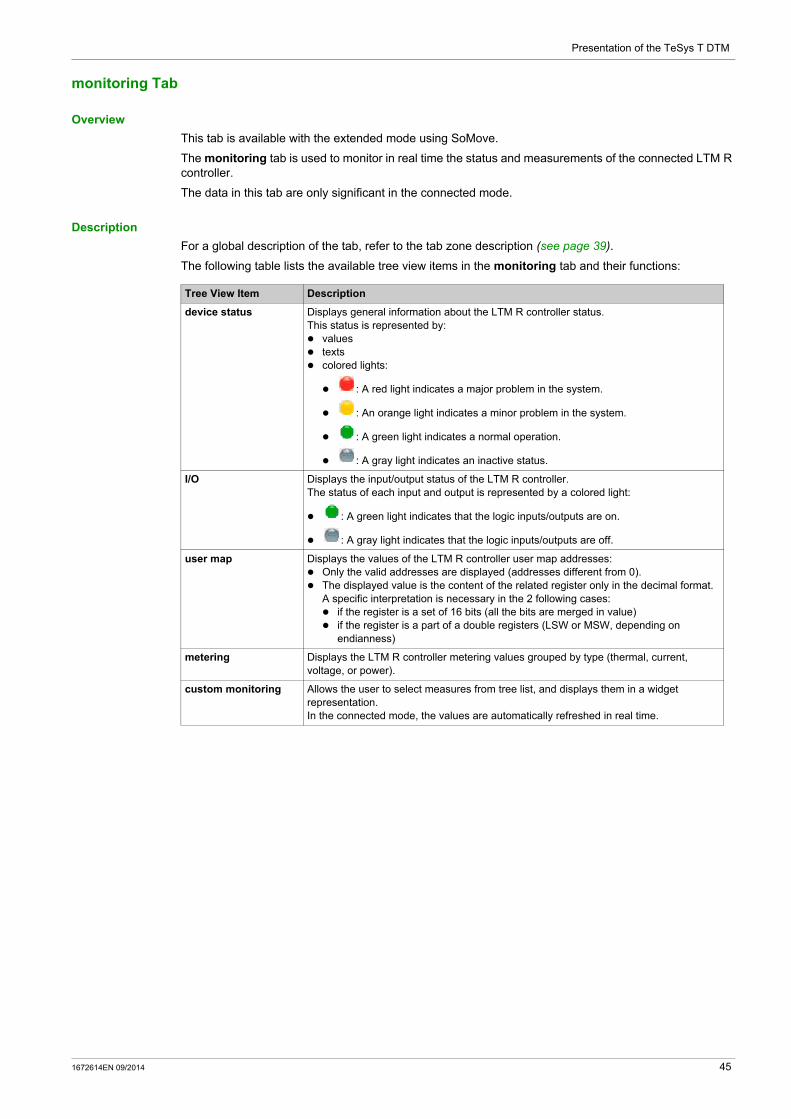
Presentation of the TeSys T DTM
monitoring Tab
Overview
This tab is available with the extended mode using SoMove.
The monitoring tab is used to monitor in real time the status and measurements of the connected LTM R controller.
The data in this tab are only significant in the connected mode.
Description
For a global description of the tab, refer to the tab zone description (see page 39).
The following table lists the available tree view items in the monitoring tab and their functions:
Tree View Item Description
device status Displays general information about the LTM R controller status.This status is represented by: values texts colored lights:
: A red light indicates a major problem in the system.
: An orange light indicates a minor problem in the system.
: A green light indicates a normal operation.
: A gray light indicates an inactive status.
I/O Displays the input/output status of the LTM R controller.The status of each input and output is represented by a colored light:
: A green light indicates that the logic inputs/outputs are on.
: A gray light indicates that the logic inputs/outputs are off.
user map Displays the values of the LTM R controller user map addresses: Only the valid addresses are displayed (addresses different from 0). The displayed value is the content of the related register only in the decimal format.
A specific interpretation is necessary in the 2 following cases: if the register is a set of 16 bits (all the bits are merged in value) if the register is a part of a double registers (LSW or MSW, depending on
endianness)
metering Displays the LTM R controller metering values grouped by type (thermal, current, voltage, or power).
custom monitoring Allows the user to select measures from tree list, and displays them in a widget representation.In the connected mode, the values are automatically refreshed in real time.
1672614EN 09/2014 45

Presentation of the TeSys T DTM
Custom Monitoring
You can select a number of parameters in the tree view to display the corresponding value with widgets in the display area.
To select a parameter displayed by widgets in the custom monitoring display area proceed as follows:
Types of Widgets
Depending on the selected parameter, 3 types of widgets can be displayed:
Step Action
1 Select the parameter to display in the tree view on the left. Multiple parameters can be selected and organized simultaneously in the display area.
2 Click the display area on the right, the value of the selected parameter is displayed by a widget at the click location. The values are automatically refreshed in real time.
3 Modify the widget type in the selection list.
Type Angular Gauge Linear Gauge Digital Display
Widget
46 1672614EN 09/2014

Presentation of the TeSys T DTM
diagnostic Tab
Overview
This tab is available with the extended mode using SoMove.
The diagnostic tab displays statistics of the connected LTM R controller.
The data in this tab is only significant in the connected mode.
Description
For a global description of this tab, refer to the tab zone description (see page 39).
This table lists tree view items available in the diagnostic tab and their functions:
Tree View Item Description
Eth Monitors the Ethernet statistics of LTM R Ethernet controller (see page 245).
statistics Displays: the LTM R controller history (see page 65) the motor history (see page 90)
1672614EN 09/2014 47

Presentation of the TeSys T DTM
48 1672614EN 09/2014
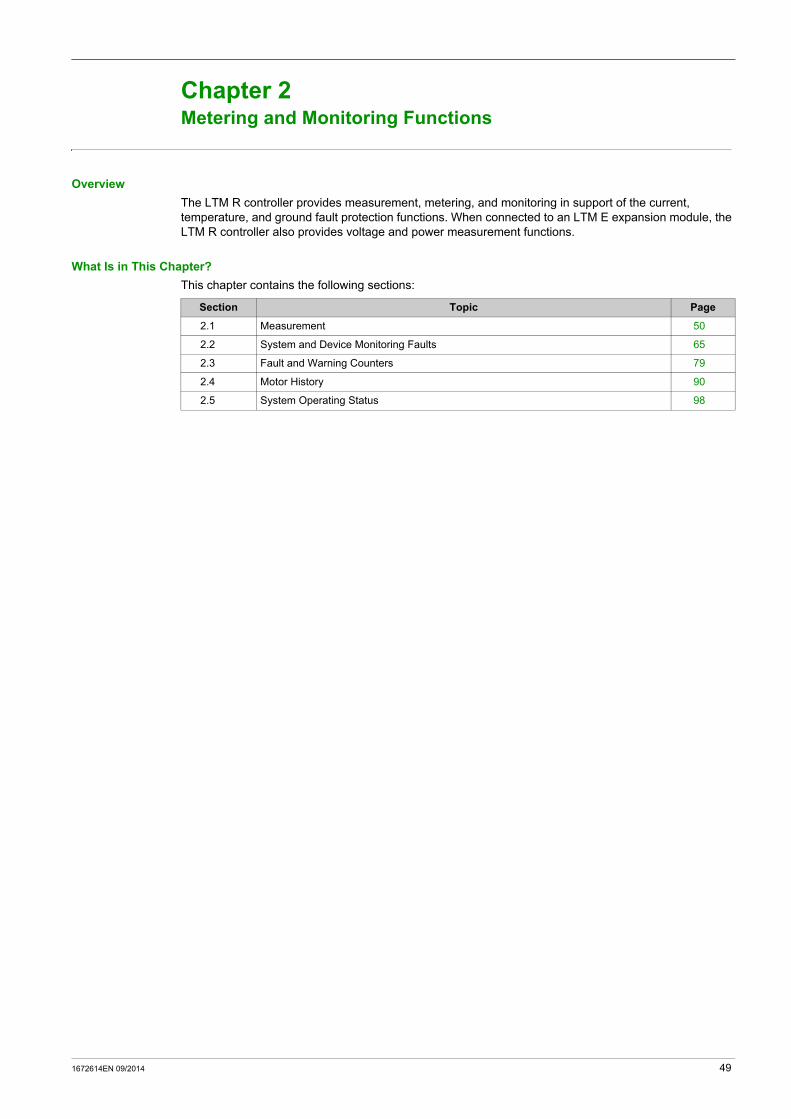
TeSys T DTM for FDT Container
Metering and Monitoring Functions
1672614EN 09/2014
Metering and Monitoring Functions
Chapter 2Metering and Monitoring Functions
Overview
The LTM R controller provides measurement, metering, and monitoring in support of the current, temperature, and ground fault protection functions. When connected to an LTM E expansion module, the LTM R controller also provides voltage and power measurement functions.
What Is in This Chapter?
This chapter contains the following sections:
Section Topic Page
2.1 Measurement 50
2.2 System and Device Monitoring Faults 65
2.3 Fault and Warning Counters 79
2.4 Motor History 90
2.5 System Operating Status 98
1672614EN 09/2014 49
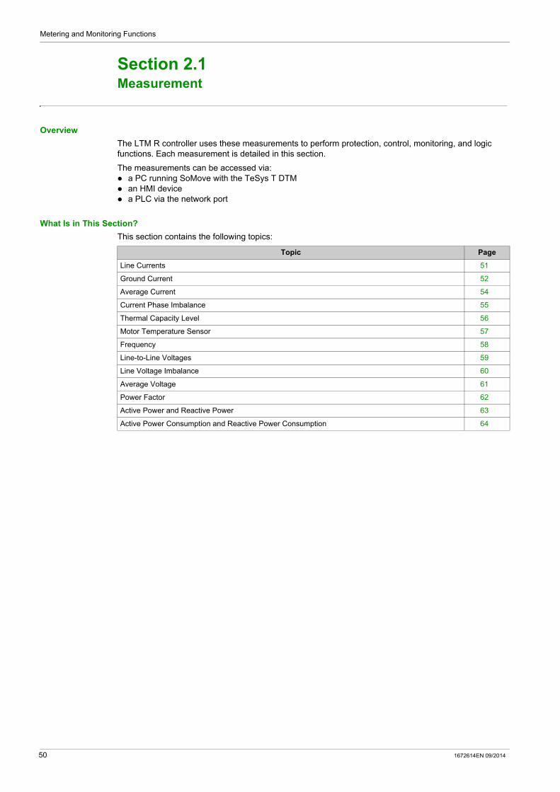
Metering and Monitoring Functions
Measurement
Section 2.1Measurement
Overview
The LTM R controller uses these measurements to perform protection, control, monitoring, and logic functions. Each measurement is detailed in this section.
The measurements can be accessed via: a PC running SoMove with the TeSys T DTM an HMI device a PLC via the network port
What Is in This Section?
This section contains the following topics:
Topic Page
Line Currents 51
Ground Current 52
Average Current 54
Current Phase Imbalance 55
Thermal Capacity Level 56
Motor Temperature Sensor 57
Frequency 58
Line-to-Line Voltages 59
Line Voltage Imbalance 60
Average Voltage 61
Power Factor 62
Active Power and Reactive Power 63
Active Power Consumption and Reactive Power Consumption 64
50 1672614EN 09/2014
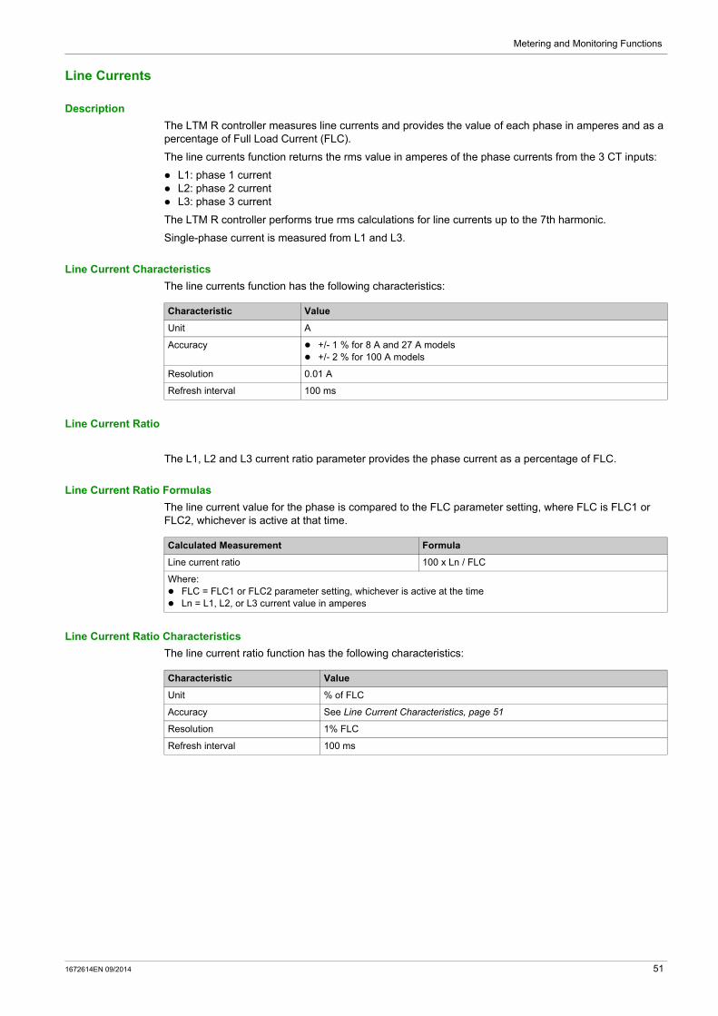
Metering and Monitoring Functions
Line Currents
Description
The LTM R controller measures line currents and provides the value of each phase in amperes and as a percentage of Full Load Current (FLC).
The line currents function returns the rms value in amperes of the phase currents from the 3 CT inputs:
L1: phase 1 current L2: phase 2 current L3: phase 3 current
The LTM R controller performs true rms calculations for line currents up to the 7th harmonic.
Single-phase current is measured from L1 and L3.
Line Current Characteristics
The line currents function has the following characteristics:
Line Current Ratio
The L1, L2 and L3 current ratio parameter provides the phase current as a percentage of FLC.
Line Current Ratio Formulas
The line current value for the phase is compared to the FLC parameter setting, where FLC is FLC1 or FLC2, whichever is active at that time.
Line Current Ratio Characteristics
The line current ratio function has the following characteristics:
Characteristic Value
Unit A
Accuracy +/- 1 % for 8 A and 27 A models +/- 2 % for 100 A models
Resolution 0.01 A
Refresh interval 100 ms
Calculated Measurement Formula
Line current ratio 100 x Ln / FLC
Where: FLC = FLC1 or FLC2 parameter setting, whichever is active at the time Ln = L1, L2, or L3 current value in amperes
Characteristic Value
Unit % of FLC
Accuracy See Line Current Characteristics, page 51
Resolution 1% FLC
Refresh interval 100 ms
1672614EN 09/2014 51

Metering and Monitoring Functions
Ground Current
Description
The LTM R controller measures ground currents and provides values in Amperes and as a percentage of FLCmin.
The internal ground current (Igr∑) is calculated by the LTM R controller from the 3 line currents measured by the load current transformers. It reports 0 when the current falls below 10 % of FLCmin.
The external ground current (Igr) is measured by the external ground current transformer connected to Z1 and Z2 terminals.
Configurable Parameters
The control channel configuration has the following configurable parameter settings:
External Ground Current Formula
The external ground current value depends on the parameter settings:
Ground Current Characteristics
The ground current function has the following characteristics:
Parameter Setting Range Factory Setting
Ground Current Mode Internal External
Internal
Ground Current Ratio None 100:1 200:1.5 1000:1 2000:1 Other Ratio
None
Ground CT Primary 1…65,535 1
Ground CT Secondary 1…65,535 1
Calculated Measurement Formula
External ground current (Current through Z1-Z2) x (Ground CT Primary) / (Ground CT Secondary)
Characteristic Value
Internal Ground Current (IgrΣ) External Ground Current (Igr)
Unit A A
Accuracy
LTM R 08xxx Igr ≥ 0.3 A +/– 10 % The greater of +/– 5 % or +/– 0.01 A
0.2 A ≤ Igr ≤ 0.3 A +/– 15 %
0.1 A ≤ Igr ≤ 0.2 A +/– 20 %
Igr < 0.1 A N/A(1)
LTM R 27xxx Igr ≥ 0.5 A +/– 10 %
0.3 A ≤ Igr ≤ 0.5 A +/– 15 %
0.2 A ≤ Igr ≤ 0.3 A +/– 20 %
Igr < 0.2 A N/A(1)
LTM R 100xxx Igr ≥ 1.0 A +/– 10 %
0.5 A ≤ Igr ≤ 1.0 A +/– 15 %
0.3 A ≤ Igr ≤ 0.5 A +/– 20 %
Igr < 0.3 A N/A(1)
Resolution 0.01 A 0.01 A
Refresh interval 100 ms 100 ms
(1) For currents of this magnitude or lower, the internal ground current function should not be used. Instead, use external ground current transformers.
52 1672614EN 09/2014
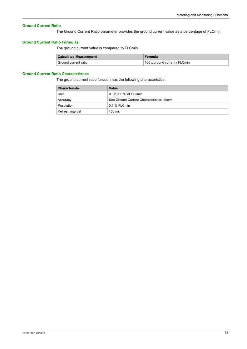
Metering and Monitoring Functions
Ground Current Ratio
The Ground Current Ratio parameter provides the ground current value as a percentage of FLCmin.
Ground Current Ratio Formulas
The ground current value is compared to FLCmin.
Ground Current Ratio Characteristics
The ground current ratio function has the following characteristics:
Calculated Measurement Formula
Ground current ratio 100 x ground current / FLCmin
Characteristic Value
Unit 0…2,000 % of FLCmin
Accuracy See Ground Current Characteristics, above
Resolution 0.1 % FLCmin
Refresh interval 100 ms
1672614EN 09/2014 53

Metering and Monitoring Functions
Average Current
Description
The LTM R controller calculates average current and provides the value for phase in amperes and as a percentage of FLC.
The average current function returns the rms value of the average current.
Average Current Formulas
The LTM R controller calculates the average current using the measured line currents. The measured values are internally summed using the following formula:
Average Current Characteristics
The average current function has the following characteristics:
Average Current Ratio
The Average Current Ratio parameter provides the average current value as a percentage of FLC.
Average Current Ratio Formulas
The average current value for the phase is compared to the FLC parameter setting, where FLC is FLC1 or FLC2, whichever is active at that time.
Average Current Ratio Characteristics
The average current ratio function has the following characteristics:
Calculated Measurement Formula
Average current, three phase motor Iavg = (L1 + L2 + L3) / 3
Average current, single-phase motor Iavg = (L1 + L3) / 2
Characteristic Value
Unit A
Accuracy +/- 1 % for 8 A and 27 A models +/- 2 % for 100 A models
Resolution 0.01 A
Refresh interval 100 ms
Calculated Measurement Formula
Average current ratio 100 x lavg / FLC
Where: FLC = FLC1 or FLC2 parameter setting, whichever is active at the time lavg = average current value in amperes
Characteristic Value
Unit % of FLC
Accuracy See Average Current Characteristics, above
Resolution 1 % FLC
Refresh interval 100 ms
54 1672614EN 09/2014

Metering and Monitoring Functions
Current Phase Imbalance
Description
The current phase imbalance function measures the maximum percentage of deviation between the average current and the individual phase currents.
Formulas
The current phase imbalance measurement is based on imbalance ratio calculated from the following formulas:
Characteristics
The line current imbalance function has the following characteristics:
Calculated Measurement Formula
Imbalance ratio of current in phase 1 (in %) Ii1 = (| L1 - Iavg | x 100) / Iavg
Imbalance ratio of current in phase 2 (in %) Ii2 = (| L2 - Iavg | x 100) / Iavg
Imbalance ratio of current in phase 3 (in %) Ii3 = (| L3 - Iavg | x 100) / Iavg
Current imbalance ratio for three phase (in %) Iimb = Max(Ii1, Ii2, Ii3)
Characteristic Value
Unit %
Accuracy +/- 1.5% for 8 A and 27 A models +/- 3% for 100 A models
Resolution 1%
Refresh interval 100 ms
1672614EN 09/2014 55
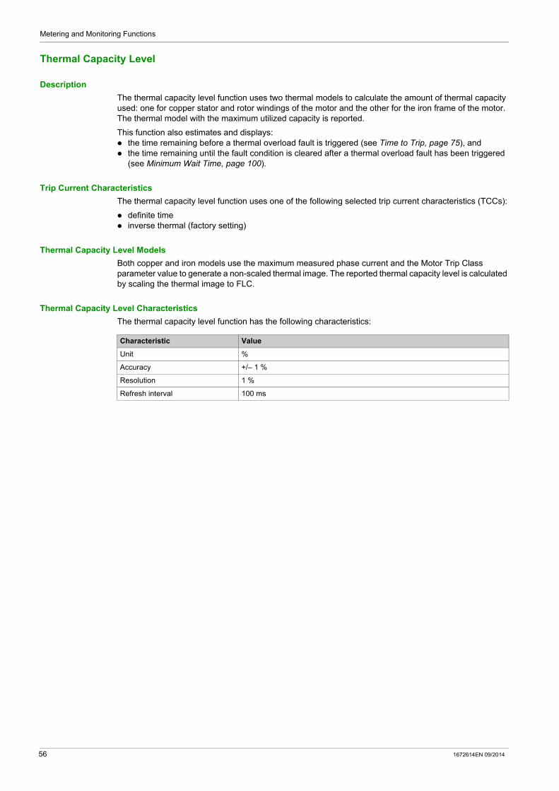
Metering and Monitoring Functions
Thermal Capacity Level
Description
The thermal capacity level function uses two thermal models to calculate the amount of thermal capacity used: one for copper stator and rotor windings of the motor and the other for the iron frame of the motor. The thermal model with the maximum utilized capacity is reported.
This function also estimates and displays: the time remaining before a thermal overload fault is triggered (see Time to Trip, page 75), and the time remaining until the fault condition is cleared after a thermal overload fault has been triggered
(see Minimum Wait Time, page 100).
Trip Current Characteristics
The thermal capacity level function uses one of the following selected trip current characteristics (TCCs):
definite time inverse thermal (factory setting)
Thermal Capacity Level Models
Both copper and iron models use the maximum measured phase current and the Motor Trip Class parameter value to generate a non-scaled thermal image. The reported thermal capacity level is calculated by scaling the thermal image to FLC.
Thermal Capacity Level Characteristics
The thermal capacity level function has the following characteristics:
Characteristic Value
Unit %
Accuracy +/– 1 %
Resolution 1 %
Refresh interval 100 ms
56 1672614EN 09/2014

Metering and Monitoring Functions
Motor Temperature Sensor
Description
The motor temperature sensor function displays: The resistance value in ohms measured by a PTC or NTC resistance temperature sensor. The temperature value in ° C or ° F measured by a PT100 temperature sensor.
Refer to the product documentation for the specific temperature sensor being used. One of 4 types of temperature sensors can be used:
PTC Binary PT100 PTC Analog NTC Analog
Characteristics
The motor temperature sensor function has the following characteristics:
Characteristic PT100 Temperature Sensor Other Temperature Sensor
Unit ° C or ° F, according to the value of the HMI Display Temperature Sensor Degree CF parameter
Ω
Accuracy +/- 2 % +/– 2 %
Resolution 1 ° C or 1 ° F 0.1 Ω
Refresh interval 500 ms 500 ms
1672614EN 09/2014 57

Metering and Monitoring Functions
Frequency
Description
The frequency function provides the value measured based on the line voltage measurements. If the frequency is unstable (+/– 2 Hz variations), the value reported is 0 until the frequency stabilizes.
If no LTM E expansion module is present, the frequency value is 0.
Characteristics
The frequency function has the following characteristics:
Characteristic Value
Unit Hz
Accuracy +/– 2%
Resolution 0.1 Hz
Refresh interval 30 ms
58 1672614EN 09/2014

Metering and Monitoring Functions
Line-to-Line Voltages
Description
The line-to-line voltages function provides the rms value of the phase-to-phase voltage (V1 to V2, V2 to V3, and V3 to V1):
L1-L2 voltage: phase 1 to phase 2 voltage L2-L3 voltage: phase 2 to phase 3 voltage L3-L1 voltage: phase 3 to phase 1 voltage
The expansion module performs true rms calculations for line-to-line voltage up to the 7th harmonic.
Single phase voltage is measured from L1 and L3.
Characteristics
The line-to-line voltages function has the following characteristics:
Characteristic Value
Unit VAC
Accuracy +/- 1 %
Resolution 1 VAC
Refresh interval 100 ms
1672614EN 09/2014 59

Metering and Monitoring Functions
Line Voltage Imbalance
Description
The line voltage imbalance function displays the maximum percentage of deviation between the average voltage and the individual line voltages.
Formulas
The line voltage imbalance calculated measurement is based on the following formulas:
Characteristics
The line voltage imbalance function has the following characteristics:
Calculated Measurement Formula
Imbalance ratio of voltage in phase 1 in % Vi1 = 100 x | V1 - Vavg | / Vavg
Imbalance ratio of voltage in phase 2 in % Vi2 = 100 x | V2 - Vavg | / Vavg
Imbalance ratio of voltage in phase 3 in % Vi3 = 100 x | V3 - Vavg | / Vavg
Voltage imbalance ratio for three phase in % Vimb = Max (Vi1, Vi2, Vi3)
Where: V1 = L1-L2 voltage (phase 1 to phase 2 voltage) V2 = L2-L3 voltage (phase 2 to phase 3 voltage) V3 = L3-L1 voltage (phase 3 to phase 1 voltage) Vavg = average voltage
Characteristic Value
Unit %
Accuracy +/– 1.5 %
Resolution 1 %
Refresh interval 100 ms
60 1672614EN 09/2014

Metering and Monitoring Functions
Average Voltage
Description
The LTM R controller calculates average voltage and provides the value in volts. The average voltage function returns the rms value of the average voltage.
Formulas
The LTM R controller calculates average voltage using the measured line-to-line voltages. The measured values are internally summed using the following formula:
Characteristics
The average voltage function has the following characteristics:
Calculated Measurement Formula
Average voltage, three phase motor Vavg = (L1-L2 voltage + L2-L3 voltage + L3-L1 voltage) / 3
Average voltage, single-phase motor Vavg = L3-L1 voltage
Characteristic Value
Unit VAC
Accuracy +/- 1%
Resolution 1 VAC
Refresh interval 100 ms
1672614EN 09/2014 61

Metering and Monitoring Functions
Power Factor
Description
The power factor function displays the phase displacement between the phase currents and phase voltages.
Formula
The Power Factor parameter (also called cosine phi or cos ϕ) represents the absolute value of the ratio of Active Power to Apparent Power.
The following diagram displays an example of the average rms current sinusoidal curve lagging slightly behind the average rms voltage sinusoidal curve, and the phase angle difference between the 2 curves:
After the phase angle (ϕ) is measured, the power factor can be calculated as the cosine of the phase angle (ϕ)—the ratio of side a (Active Power) over the hypotenuse h (Apparent Power):
Characteristics
The active power function has the following characteristics:
Characteristic Value
Accuracy +/- 10 % for cos ϕ ≥ 0.6
Resolution 0.01
Refresh interval 30 ms (typical)(1)
(1) The refresh interval depends on the frequency.
62 1672614EN 09/2014

Metering and Monitoring Functions
Active Power and Reactive Power
Description
The calculation of the active power and reactive power is based on the: average rms phase voltage of L1, L2, L3 average rms phase current of L1, L2, L3 power factor number of phases
Formulas
Active power, also known as true power, measures average rms power. It is derived from the following formulas:
The reactive power measurement is derived from the following formulas:
Characteristics
The active and reactive power functions have the following characteristics:
Calculated Measurement Formula
Active power for three phase motor √3 x lavg x Vavg x cosϕ
Active power for single-phase motor lavg x Vavg x cosϕ
Where: Iavg = Average rms current Vavg = Average rms voltage
Calculated Measurement Formula
Reactive power for three phase motor √3 x lavg x Vavg x sinϕ
Reactive power for single-phase motor lavg x Vavg x sinϕ
Where: Iavg = Average rms current Vavg = Average rms voltage
Characteristic Active Power Reactive Power
Unit kW kVAR
Accuracy +/- 15 % +/- 15 %
Resolution 0.1 kW 0.1 kVAR
Refresh interval 100 ms 100 ms
1672614EN 09/2014 63

Metering and Monitoring Functions
Active Power Consumption and Reactive Power Consumption
Description
The active and reactive power consumption functions display the accumulated total of the active and reactive electrical power delivered, and used or consumed by the load.
Characteristics
The active and reactive power consumption functions have the following characteristics:
Characteristic Active Power Consumption Reactive Power Consumption
Unit kWh kVARh
Accuracy +/- 15 % +/- 15 %
Resolution 0.1 kWh 0.1 kVARh
Refresh interval 100 ms 100 ms
64 1672614EN 09/2014

Metering and Monitoring Functions
System and Device Monitoring Faults
Section 2.2System and Device Monitoring Faults
Overview
The LTM R controller and the LTM E expansion module detect faults which affect the LTM R controller ability to work properly (internal controller check and check of communications, wiring, and configuration errors).
The system and device monitoring fault records can be accessed via: a PC running SoMove with the TeSys T DTM an HMI device a PLC via the network port
What Is in This Section?
This section contains the following topics:
Topic Page
Controller Internal Fault 66
Controller Internal Temperature 67
Control Command Error Diagnostic 68
Wiring Faults 70
Configuration Checksum 72
Communication Loss 73
Time to Trip 75
LTM R Configuration Fault 76
LTM E Configuration Fault and Warning 77
External Fault 78
1672614EN 09/2014 65
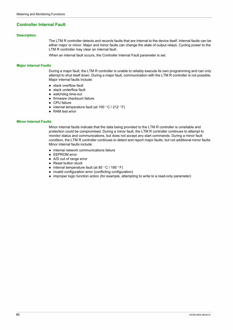
Metering and Monitoring Functions
Controller Internal Fault
Description
The LTM R controller detects and records faults that are internal to the device itself. Internal faults can be either major or minor. Major and minor faults can change the state of output relays. Cycling power to the LTM R controller may clear an internal fault.
When an internal fault occurs, the Controller Internal Fault parameter is set.
Major Internal Faults
During a major fault, the LTM R controller is unable to reliably execute its own programming and can only attempt to shut itself down. During a major fault, communication with the LTM R controller is not possible. Major internal faults include:
stack overflow fault stack underflow fault watchdog time-out firmware checksum failure CPU failure internal temperature fault (at 100 ° C / 212 ° F) RAM test error
Minor Internal Faults
Minor internal faults indicate that the data being provided to the LTM R controller is unreliable and protection could be compromised. During a minor fault, the LTM R controller continues to attempt to monitor status and communications, but does not accept any start commands. During a minor fault condition, the LTM R controller continues to detect and report major faults, but not additional minor faults. Minor internal faults include:
internal network communications failure EEPROM error A/D out of range error Reset button stuck internal temperature fault (at 85 ° C / 185 ° F) invalid configuration error (conflicting configuration) improper logic function action (for example, attempting to write to a read-only parameter)
66 1672614EN 09/2014

Metering and Monitoring Functions
Controller Internal Temperature
Description
The LTM R controller monitors its Controller Internal Temperature, and reports warning, minor fault, and major fault conditions. Fault detection cannot be disabled. Warning detection can be enabled or disabled.
The controller retains a record of the highest attained internal temperature.
Characteristics
The Controller Internal Temperature measured values have the following characteristics:
Parameters
The Controller Internal Temperature function includes one editable parameter:
The Controller Internal Temperature function includes the following fixed warning and fault thresholds:
A warning condition ceases when LTM R Controller Internal Temperature falls below 80 ° C (176 ° F).
Block Diagram
T TemperatureT > 80 ° C (176 ° F) Fixed warning thresholdT > 85 ° C (185 ° F) Fixed minor fault thresholdT > 100 ° C (212 ° F) Fixed major fault threshold
Maximum Internal Controller Temperature
The Controller Internal Temperature Max parameter contains the highest internal temperature, expressed in ° C, detected by the LTM R controller’s internal temperature sensor. The LTM R controller updates this value whenever it detects an internal temperature greater than the current value.
The maximum internal temperature value is not cleared when factory settings are restored using the Clear All Command, or when statistics are reset using a Clear Statistics Command.
Characteristic Value
Unit ° C
Accuracy +/- 4 ° C (+/- 7.2 ° F)
Resolution 1 ° C (1.8 ° F)
Refresh interval 100 ms
Parameter Setting Range Factory Setting
Controller internal temperature warning enable Enable Disable
Enable
Condition Fixed Threshold Value Sets Parameter
Internal temperature warning 80 ° C (176 ° F) Controller Internal Temperature Warning
Internal temperature minor fault 85 ° C (185 ° F) Controller Internal Fault
Internal temperature major fault 100 ° C (212 ° F)
1672614EN 09/2014 67

Metering and Monitoring Functions
Control Command Error Diagnostic
Description
The LTM R controller performs diagnostic tests that detect and monitor the proper functionality of control commands.
There are 4 control command diagnostic functions:
Start Command Check Run Check Back Stop Command Check Stop Check Back
Parameter Settings
All 4 diagnostic functions are enabled and disabled as a group. The configurable parameter settings are:
Start Command Check
The Start Command Check begins after a Start command, and causes the LTM R controller to monitor the main circuit to ensure that current is flowing.
The Start Command Check reports a Start Command fault or warning if current is not detected after a delay of 1 second.
The Start Command Check conditions ends if the motor is in Run state and the LTM R controller detects that the current is equal or more than 10% of FLCmin.
Run Check Back
The Run Check Back causes the LTM R controller to continuously monitor the main circuit to ensure current is flowing.
The Run Check Back reports a fault or warning if average phase current is not detected for longer than 0.5 seconds without a Stop command.
The Run Check Back ends when a Stop command executes.
Stop Command Check
The Stop Command Check begins after a Stop command, and causes the LTM R controller to monitor the main circuit and ensure that no current is flowing. The Stop Command Check reports a fault or warning if current is detected after a delay of 1 second. The Stop Command Check ends if the LTM R controller detects that the current is equal or less than
5% of FLCmin.
Stop Check Back
The Stop Check Back causes the LTM R controller to continuously monitor the main circuit to ensure that no current is flowing.
The Stop Check Back reports a Stop Check Back fault or warning if average phase current is detected for longer than 0.5 seconds after a Stop command.
The Stop Check Back condition ends when a Run command executes.
Parameters Setting Range Factory Setting
Diagnostic Fault Enable Yes/No Yes
Diagnostic Warning Enable Yes/No Yes
68 1672614EN 09/2014

Metering and Monitoring Functions
Timing Sequence
The following diagram is an example of the timing sequence for the Start Command Check and Stop Command Check:
1 Normal operation2 Fault or warning condition3 The LTM R controller monitors the main circuit to detect current4 The LTM R controller monitors the main circuit to detect no current5 The LTM R controller reports a Start Command Check fault and/or warning if current is not detected after 1 second 6 The LTM R controller reports a Stop Command Check fault and or warning if current is detected after 1 second
The following diagram is an example of the timing sequence for the Run Check Back and Stop Check Back:
1 Normal operation2 Fault or warning condition3 After the motor enters the run state, the LTM R controller continuously monitors the main circuit to detect current
until a Stop command is given or the function is disabled4 The LTM R controller continuously monitors the main circuit to detect no current until a Start command is given or
the function is disabled5 The LTM R controller reports a Run Check Back fault and/or warning if the current is not detected for longer than
0.5 seconds without a Stop command6 The LTM R controller reports a Stop Check Back fault or warning if the current is detected for longer than
0.5 seconds without a Start command7 No current flowing for less than 0.5 seconds8 Current flowing for less than 0.5 seconds
1672614EN 09/2014 69
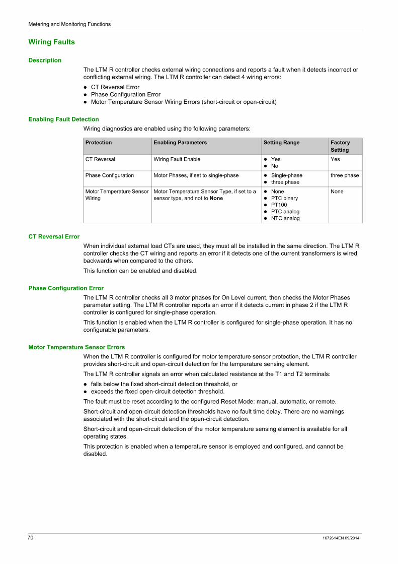
Metering and Monitoring Functions
Wiring Faults
Description
The LTM R controller checks external wiring connections and reports a fault when it detects incorrect or conflicting external wiring. The LTM R controller can detect 4 wiring errors:
CT Reversal Error Phase Configuration Error Motor Temperature Sensor Wiring Errors (short-circuit or open-circuit)
Enabling Fault Detection
Wiring diagnostics are enabled using the following parameters:
CT Reversal Error
When individual external load CTs are used, they must all be installed in the same direction. The LTM R controller checks the CT wiring and reports an error if it detects one of the current transformers is wired backwards when compared to the others.
This function can be enabled and disabled.
Phase Configuration Error
The LTM R controller checks all 3 motor phases for On Level current, then checks the Motor Phases parameter setting. The LTM R controller reports an error if it detects current in phase 2 if the LTM R controller is configured for single-phase operation.
This function is enabled when the LTM R controller is configured for single-phase operation. It has no configurable parameters.
Motor Temperature Sensor Errors
When the LTM R controller is configured for motor temperature sensor protection, the LTM R controller provides short-circuit and open-circuit detection for the temperature sensing element.
The LTM R controller signals an error when calculated resistance at the T1 and T2 terminals:
falls below the fixed short-circuit detection threshold, or exceeds the fixed open-circuit detection threshold.
The fault must be reset according to the configured Reset Mode: manual, automatic, or remote.
Short-circuit and open-circuit detection thresholds have no fault time delay. There are no warnings associated with the short-circuit and the open-circuit detection.
Short-circuit and open-circuit detection of the motor temperature sensing element is available for all operating states.
This protection is enabled when a temperature sensor is employed and configured, and cannot be disabled.
Protection Enabling Parameters Setting Range Factory Setting
CT Reversal Wiring Fault Enable Yes No
Yes
Phase Configuration Motor Phases, if set to single-phase Single-phase three phase
three phase
Motor Temperature Sensor Wiring
Motor Temperature Sensor Type, if set to a sensor type, and not to None
None PTC binary PT100 PTC analog NTC analog
None
70 1672614EN 09/2014
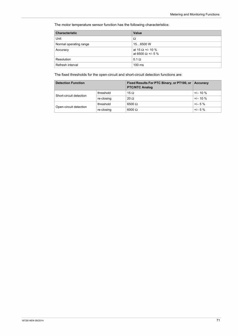
Metering and Monitoring Functions
The motor temperature sensor function has the following characteristics:
The fixed thresholds for the open-circuit and short-circuit detection functions are:
Characteristic Value
Unit Ω
Normal operating range 15…6500 W
Accuracy at 15 Ω: +/- 10 % at 6500 Ω: +/- 5 %
Resolution 0.1 Ω
Refresh interval 100 ms
Detection Function Fixed Results For PTC Binary, or PT100, or PTC/NTC Analog
Accuracy
Short-circuit detection threshold 15 Ω +/– 10 %
re-closing 20 Ω +/– 10 %
Open-circuit detectionthreshold 6500 Ω +/– 5 %
re-closing 6000 Ω +/– 5 %
1672614EN 09/2014 71

Metering and Monitoring Functions
Configuration Checksum
Description
The LTM R controller calculates a checksum of parameters based on all configuration registers. The EEPROM error code (64) is reported.
72 1672614EN 09/2014

Metering and Monitoring Functions
Communication Loss
Description
The LTM R controller monitors communication through:
the network port the HMI port
Network Port Parameter Settings
The LTM R controller monitors network communication creates both a fault and a warning report when the network communications are lost.
The network port communications have the following configurable settings:
HMI Port Parameter Settings
The LTM R controller monitors HMI port communications and reports both a warning and a fault if no valid communication has been received by the HMI port for longer than 7 seconds.
The HMI port communication has the following fixed and configurable settings:
On LTM R Version... The communication loss...
LTMR••C•• LTMR••D•• LTMR••P••
Is detected as part of the protocol management, without specific adjustable parameters.
LTMR••M•• Is detected if no communication exchanges occurred for a time period equal to, or longer than, the network port comm loss timeout.
LTMR••E•• Is detected if no communication exchanges occurred with the Master IP for a time period equal to, or longer than, the network port communication loss timeout.
Parameter Setting Range Factory Setting
Network port fault enable Enable/Disable Enable
Network port warning enable Enable/Disable Enable
Network port comm loss timeout (Modbus, EtherNet/IP and Modbus/TCP only)
0...99.99 s In increments of 0.01 s
2 s
Network port fallback setting(1) Hold Run O.1, O.2 off O.1, O.2 on O.1 off O.2 off
O.1, O.2 off
Master IP address (EtherNet/IP and Modbus/TCP only)
0.0.0.0 to 255.255.255.255 0.0.0.0
(1) The operating mode affects the configurable parameters for the network port fallback settings.
Parameter Setting Range Factory Setting
HMI port fault enable Enable/Disable Enable
HMI port warning enable Enable/Disable Enable
HMI port fallback setting(1) Hold Run O.1, O.2 off O.1, O.2 on O.1 off O.2 off
O.1, O.2 off
(1) The operating mode affects the configurable parameters for the HMI port fallback settings.
1672614EN 09/2014 73
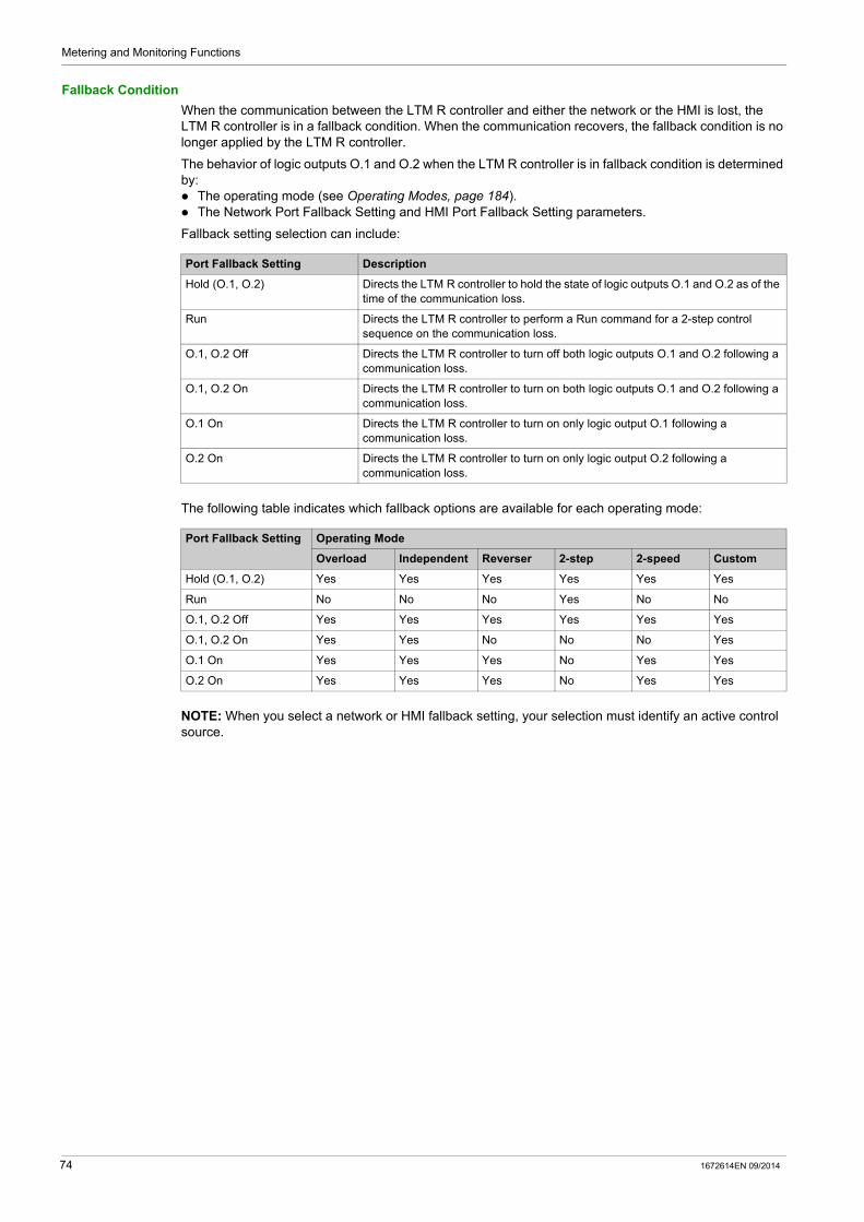
Metering and Monitoring Functions
Fallback Condition
When the communication between the LTM R controller and either the network or the HMI is lost, the LTM R controller is in a fallback condition. When the communication recovers, the fallback condition is no longer applied by the LTM R controller.
The behavior of logic outputs O.1 and O.2 when the LTM R controller is in fallback condition is determined by: The operating mode (see Operating Modes, page 184). The Network Port Fallback Setting and HMI Port Fallback Setting parameters.
Fallback setting selection can include:
The following table indicates which fallback options are available for each operating mode:
NOTE: When you select a network or HMI fallback setting, your selection must identify an active control source.
Port Fallback Setting Description
Hold (O.1, O.2) Directs the LTM R controller to hold the state of logic outputs O.1 and O.2 as of the time of the communication loss.
Run Directs the LTM R controller to perform a Run command for a 2-step control sequence on the communication loss.
O.1, O.2 Off Directs the LTM R controller to turn off both logic outputs O.1 and O.2 following a communication loss.
O.1, O.2 On Directs the LTM R controller to turn on both logic outputs O.1 and O.2 following a communication loss.
O.1 On Directs the LTM R controller to turn on only logic output O.1 following a communication loss.
O.2 On Directs the LTM R controller to turn on only logic output O.2 following a communication loss.
Port Fallback Setting Operating Mode
Overload Independent Reverser 2-step 2-speed Custom
Hold (O.1, O.2) Yes Yes Yes Yes Yes Yes
Run No No No Yes No No
O.1, O.2 Off Yes Yes Yes Yes Yes Yes
O.1, O.2 On Yes Yes No No No Yes
O.1 On Yes Yes Yes No Yes Yes
O.2 On Yes Yes Yes No Yes Yes
74 1672614EN 09/2014
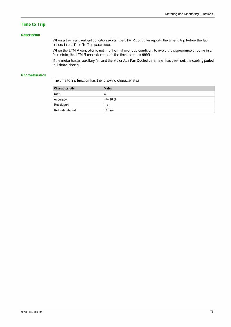
Metering and Monitoring Functions
Time to Trip
Description
When a thermal overload condition exists, the LTM R controller reports the time to trip before the fault occurs in the Time To Trip parameter.
When the LTM R controller is not in a thermal overload condition, to avoid the appearance of being in a fault state, the LTM R controller reports the time to trip as 9999.
If the motor has an auxiliary fan and the Motor Aux Fan Cooled parameter has been set, the cooling period is 4 times shorter.
Characteristics
The time to trip function has the following characteristics:
Characteristic Value
Unit s
Accuracy +/– 10 %
Resolution 1 s
Refresh interval 100 ms
1672614EN 09/2014 75

Metering and Monitoring Functions
LTM R Configuration Fault
Description
The LTM R controller checks the Load CT parameters set in configuration mode.
An LTM R configuration fault is detected when the Load CT Primary, Load CT Secondary, and Load CT Multiple Passes parameters are not consistent, and generates a System and Device Monitoring Fault. The fault condition is cleared once the parameters are correct. The LTM R controller remains in configuration mode as long as the parameters are not consistent.
76 1672614EN 09/2014
Metering and Monitoring Functions
LTM E Configuration Fault and Warning
Description
The LTM R controller checks the presence of the LTM E expansion module. Its absence generates a System and Device Monitoring Fault.
LTM E Configuration Fault
LTM E configuration fault: If LTM E based protection faults are enabled but no LTM E expansion module is present, this will cause
an LTM E configuration fault. It does not have any delay setting. The fault condition clears when no protection fault requiring an LTM E is enabled, or when the LTM R
has been power-cycled with an appropriate LTM E being present.
LTM E Configuration Warning
LTM E configuration warning: If LTM E based protection warnings are enabled but no LTM E expansion module is present, this will
cause an LTM E configuration warning. The warning clears when no protection warning requiring an LTM E is enabled, or when the LTM R has
been power-cycled with an appropriate LTM E being present.
1672614EN 09/2014 77

Metering and Monitoring Functions
External Fault
Description
The LTM R controller has an external fault feature, which detects if an error happened on an external system linked to it.
An external fault is triggered by setting a bit in the custom logic command register 1 (see table below). This external fault sets the controller into a fault state based on different parameters in the system.
An external fault can be reset only by clearing the external fault bit in the register.
External Fault Parameter Settings
Parameter Description
Custom logic external fault command The value is written
External system fault Reads Custom logic external fault command parameter
Fault code Number is 16: External fault set by program customized with custom logic editor
78 1672614EN 09/2014
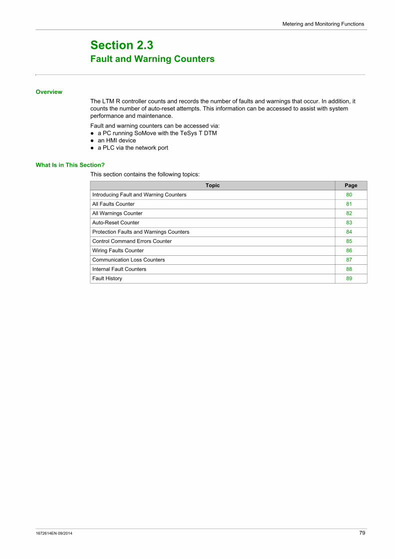
Metering and Monitoring Functions
Fault and Warning Counters
Section 2.3Fault and Warning Counters
Overview
The LTM R controller counts and records the number of faults and warnings that occur. In addition, it counts the number of auto-reset attempts. This information can be accessed to assist with system performance and maintenance.
Fault and warning counters can be accessed via: a PC running SoMove with the TeSys T DTM an HMI device a PLC via the network port
What Is in This Section?
This section contains the following topics:
Topic Page
Introducing Fault and Warning Counters 80
All Faults Counter 81
All Warnings Counter 82
Auto-Reset Counter 83
Protection Faults and Warnings Counters 84
Control Command Errors Counter 85
Wiring Faults Counter 86
Communication Loss Counters 87
Internal Fault Counters 88
Fault History 89
1672614EN 09/2014 79

Metering and Monitoring Functions
Introducing Fault and Warning Counters
Detecting Warnings
If a warning detection function is enabled, the LTM R controller detects a warning immediately when the monitored value rises above, or falls below, a threshold setting.
Detecting Faults
Before the LTM R controller detects a fault, certain preconditions must exist. These conditions can include the fault detecting function must be enabled, a monitored value (for example, current, voltage, or thermal resistance) must rise above, or fall below,
a threshold setting, the monitored value must remain above or below the threshold setting for a specified time duration.
Counters
When a fault occurs, the LTM R controller increments at least 2 counters: a counter for the specific fault detecting function, and a counter for all faults.
When a warning occurs, the LTM R controller increments a single counter for all warnings. However, when the LTM R controller detects a thermal overload warning, it also increments the thermal overload warnings counter.
A counter contains a value from 0 to 65,535 and increments by a value of 1 when a fault, warning, or reset event occurs. A counter stops incrementing when it reaches a value of 65,535.
When a fault is automatically reset, the LTM R controller increments only the auto-resets counter. Counters are saved on power loss.
Clearing Counters
All fault and warning counters are reset to 0 by executing the Clear Statistics Command or Clear All Command.
80 1672614EN 09/2014

Metering and Monitoring Functions
All Faults Counter
Description
The Faults Count parameter contains the number of faults that have occurred since the Clear All Statistics Command last executed.
The Faults Count parameter increments by a value of 1 when the LTM R controller detects any fault.
1672614EN 09/2014 81

Metering and Monitoring Functions
All Warnings Counter
Description
The Warnings Count parameter contains the number of warnings that have occurred since the Clear All Statistics Command last executed.
The Warnings Count parameter increments by a value of 1 when the LTM R controller detects any warning.
82 1672614EN 09/2014

Metering and Monitoring Functions
Auto-Reset Counter
Description
The Auto-Reset Count parameter contains the number of times the LTM R controller attempted, but failed, to auto-reset a fault. This parameter is used for the 3 auto-reset fault groups.
If an auto-reset attempt is successful (defined as the same fault not recurring within 60 s), this counter is reset to zero. If a fault is reset either manually or remotely, the counter is not incremented.
For information on fault management, see Fault Management and Clear Commands, page 206.
1672614EN 09/2014 83

Metering and Monitoring Functions
Protection Faults and Warnings Counters
Protection Fault Counts
Protection fault counters include: Current Phase Imbalance Faults Count Current Phase Loss Faults Count Current Phase Reversal Faults Count Ground Current Faults Count Jam Faults Count Long Start Faults Count Motor Temp Sensor Faults Count Over Power Factor Faults Count Overcurrent Faults Count Overpower Faults Count Overvoltage Faults Count Thermal Overload Faults Count Under Power Factor Faults Count Undercurrent Faults Count Underpower Faults Count Undervoltage Faults Count Voltage Phase Imbalance Faults Count Voltage Phase Loss Faults Count Voltage Phase Reversal Faults Count
Protection Warning Counts
The Thermal Overload Warnings Count parameter contains the total number of warnings for the thermal overload protection function.
When any warning occurs, including a thermal overload warning, the LTM R controller increments the Warnings Count parameter.
84 1672614EN 09/2014

Metering and Monitoring Functions
Control Command Errors Counter
Description
A Diagnostic Fault occurs when the LTM R controller detects any of the following control command errors:
Start Command Check errors Stop Command Check errors Stop Check Back errors Run Check Back errors
For information on these control command functions, see Control Command Error Diagnostic, page 68.
1672614EN 09/2014 85

Metering and Monitoring Functions
Wiring Faults Counter
Description
The Wiring Faults Count parameter contains the total number of the following wiring faults that have occurred since the Clear Statistics Command last executed:
Wiring Fault, which is triggered by a: CT Reversal Error Phase Configuration Error Motor Temperature Sensor Wiring Error
Voltage Phase Reversal Fault Current Phase Reversal Fault
The LTM R controller increments the Wiring Faults Count parameter by a value of 1 each time any one of the above 3 faults occurs. For information on connection errors and related faults, see Wiring Faults, page 70.
86 1672614EN 09/2014

Metering and Monitoring Functions
Communication Loss Counters
Description
Faults detected for the following communication functions:
Counter Contains
HMI Port Faults Count The number of times communications via the HMI port was lost.
Network Port Internal Faults Count The number of internal faults experienced by the network module, reported by the network module to the LTM R controller.
Network Port Config Faults Count The number of major faults experienced by the network module, exclusive of network module internal faults, reported by the network module to the LTM R controller.
Network Port Faults Count The number of times communications via the network port was lost.
1672614EN 09/2014 87

Metering and Monitoring Functions
Internal Fault Counters
Description
Faults detected for the following internal faults:
Counter Contains
Controller Internal Faults Count The number of major and minor internal faults.For information on internal faults, see Controller Internal Fault, page 66.
Internal Port Faults Count The number of LTM R controller internal communication faults, plus the number of failed attempts to identify the network communication module.
88 1672614EN 09/2014
Metering and Monitoring Functions
Fault History
Fault History
The LTM R controller stores a history of LTM R controller data that was recorded at the time of the last 5 detected faults. Fault n-0 contains the most recent fault record, and fault n-4 contains the oldest retained fault record.
Each fault record includes:
Fault Code Date and Time Value of Settings Motor Full Load Current Ratio (% of FLCmax)
Value of Measurements Thermal Capacity Level
Average Current Ratio
L1, L2, L3 Current Ratio
Ground Current Ratio
Full Load Current Max
Current Phase Imbalance
Voltage Phase Imbalance
Power Factor
Frequency
Motor Temp Sensor
Average Voltage
L3-L1 Voltage, L1-L2 Voltage, L2-L3 Voltage
Active Power
1672614EN 09/2014 89
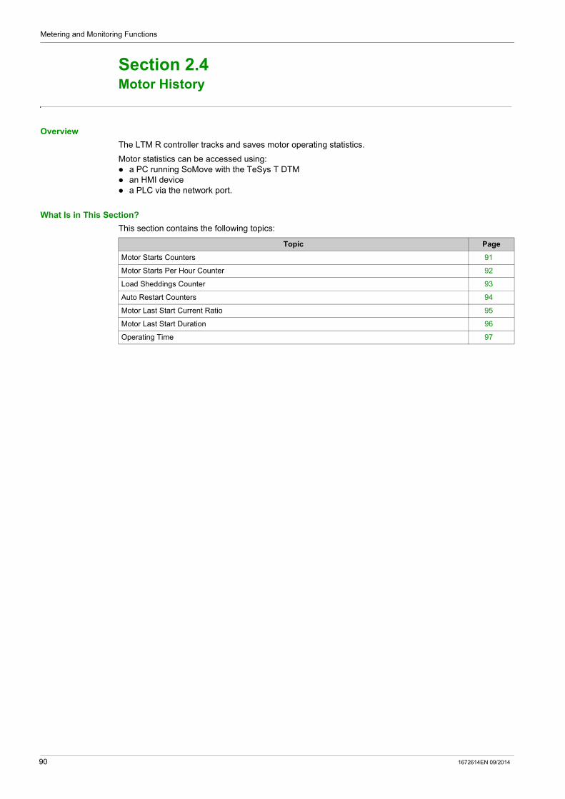
Metering and Monitoring Functions
Motor History
Section 2.4Motor History
Overview
The LTM R controller tracks and saves motor operating statistics.
Motor statistics can be accessed using: a PC running SoMove with the TeSys T DTM an HMI device a PLC via the network port.
What Is in This Section?
This section contains the following topics:
Topic Page
Motor Starts Counters 91
Motor Starts Per Hour Counter 92
Load Sheddings Counter 93
Auto Restart Counters 94
Motor Last Start Current Ratio 95
Motor Last Start Duration 96
Operating Time 97
90 1672614EN 09/2014

Metering and Monitoring Functions
Motor Starts Counters
Description
The LTM R controller tracks motor starts and records the data as a statistic that can be retrieved for operational analysis. The following statistics are tracked:
Motor Starts Count Motor LO1 Closings Count (logic output O.1 starts) Motor LO2 Closings Count (logic output O.2 starts)
The Clear Statistics Command resets the Motor Starts Count parameter to 0.
NOTE: The Motor LO1 Closings Count and Motor LO2 Closings Count parameters cannot be reset to 0, because these parameters together indicate the usage of the relay outputs over time.
1672614EN 09/2014 91

Metering and Monitoring Functions
Motor Starts Per Hour Counter
Description
The LTM R controller tracks the number of motor starts during the past hour and records this figure in the Motor Starts Per Hour Count parameter.
The LTM R controller sums start in 5 minute intervals with an accuracy of 1 interval (+0/– 5 minutes), which means that the parameter will contain the total number of starts within either the previous 60 minutes or the previous 55 minutes.
This function is used as a maintenance function to avoid thermal strain on the motor.
Characteristics
The motor starts per hour function has the following characteristics:
Characteristic Value
Accuracy 5 minutes (+ 0/– 5 minutes)
Resolution 5 minutes
Refresh interval 100 ms
92 1672614EN 09/2014

Metering and Monitoring Functions
Load Sheddings Counter
Description
The Load Sheddings Count parameter contains the number of times the load sheddings protection function has been activated since the last Clear Statistics Command.
For information on the Load Sheddings protection function, see Load Shedding, page 157.
1672614EN 09/2014 93

Metering and Monitoring Functions
Auto Restart Counters
Description
There are 3 types of counting statistics: Auto restart immediate count Auto restart delayed count Auto restart manual count
For information on the Auto restart protection function, see Automatic Restart, page 159.
94 1672614EN 09/2014

Metering and Monitoring Functions
Motor Last Start Current Ratio
Description
The LTM R controller measures the maximum current level reached during the last start of the motor and reports the value in the Motor Last Start Current Ratio parameter for analysis of the system for maintenance purposes.
This value may also be used to help configure the long start threshold setting in the long start protection function.
The value is not stored in the non-volatile memory: it is lost at a power cycle.
Characteristics
The motor last start current ratio function has the following characteristics:
Characteristic Value
Unit % of FLC
Accuracy +/- 1 % for 8 A and 27 A models +/- 2 % for 100 A models
Resolution 1 % FLC
Refresh interval 100 ms
1672614EN 09/2014 95

Metering and Monitoring Functions
Motor Last Start Duration
Description
The LTM R controller tracks the duration of the last motor start and reports the value in the Motor Last Start Duration parameter for analysis of the system for maintenance purposes.
This value may also be useful in setting the long start delay timeout used in the long start and definite trip overload protection functions.
The value is not stored in the non-volatile memory: it is lost at a power cycle.
Characteristics
The motor last start duration function has the following characteristics:
Characteristic Value
Unit s
Accuracy +/– 1 %
Resolution 1 s
Refresh interval 1 s
96 1672614EN 09/2014

Metering and Monitoring Functions
Operating Time
Description
The LTM R controller tracks motor operating time and records the value in the Operating Time parameter. Use this information to help schedule motor maintenance, such as lubrication, inspection, and replacement.
1672614EN 09/2014 97
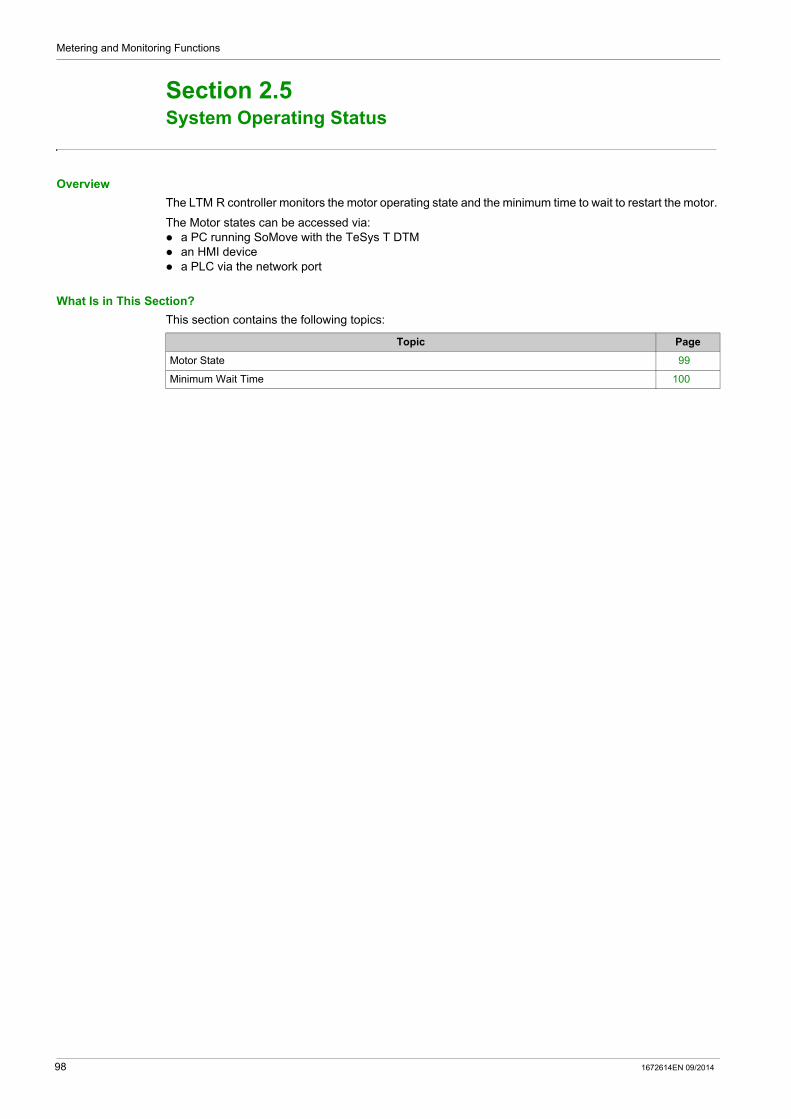
Metering and Monitoring Functions
System Operating Status
Section 2.5System Operating Status
Overview
The LTM R controller monitors the motor operating state and the minimum time to wait to restart the motor.
The Motor states can be accessed via: a PC running SoMove with the TeSys T DTM an HMI device a PLC via the network port
What Is in This Section?
This section contains the following topics:
Topic Page
Motor State 99
Minimum Wait Time 100
98 1672614EN 09/2014

Metering and Monitoring Functions
Motor State
Description
The LTM R controller tracks the motor state and reports the following states by setting the corresponding boolean parameters:
Motor state Parameter
Run Motor Running
Ready System Ready
Start Motor Starting
1672614EN 09/2014 99
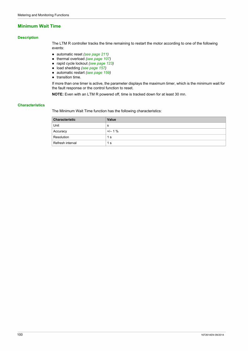
Metering and Monitoring Functions
Minimum Wait Time
Description
The LTM R controller tracks the time remaining to restart the motor according to one of the following events:
automatic reset (see page 211) thermal overload (see page 107) rapid cycle lockout (see page 123) load shedding (see page 157) automatic restart (see page 159) transition time.
If more than one timer is active, the parameter displays the maximum timer, which is the minimum wait for the fault response or the control function to reset.
NOTE: Even with an LTM R powered off, time is tracked down for at least 30 mn.
Characteristics
The Minimum Wait Time function has the following characteristics:
Characteristic Value
Unit s
Accuracy +/– 1 %
Resolution 1 s
Refresh interval 1 s
100 1672614EN 09/2014
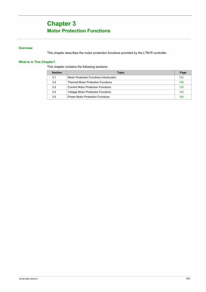
TeSys T DTM for FDT Container
Motor Protection Functions
1672614EN 09/2014
Motor Protection Functions
Chapter 3Motor Protection Functions
Overview
This chapter describes the motor protection functions provided by the LTM R controller.
What Is in This Chapter?
This chapter contains the following sections:
Section Topic Page
3.1 Motor Protection Functions Introduction 102
3.2 Thermal Motor Protection Functions 106
3.3 Current Motor Protection Functions 125
3.4 Voltage Motor Protection Functions 145
3.5 Power Motor Protection Functions 163
1672614EN 09/2014 101

Motor Protection Functions
Motor Protection Functions Introduction
Section 3.1Motor Protection Functions Introduction
Overview
This section introduces you to the motor protection functions provided by the LTM R controller, including protection parameters and characteristics.
What Is in This Section?
This section contains the following topics:
Topic Page
Definitions 103
Motor Protection Characteristics 104
102 1672614EN 09/2014
Motor Protection Functions
Definitions
Defined Functions and Data
The LTM R controller monitors current, ground-current and motor temperature sensor parameters. When the LTM R controller is connected to an expansion module, it also monitors voltage and power parameters. The LTM R controller uses these parameters in protection functions to detect fault and warning conditions.The LTM R controller’s response to fault and warning conditions is fixed for the predefined operating modes. Logic output O.4 activates on a fault, and logic output O.3 activates on a warning. For more information about predefined operating modes, see Operating Modes, page 184.
You can configure these motor protection functions to detect the existence of undesirable operating conditions that, if not resolved, can cause motor and equipment damage.
All motor protection functions include fault detection, and most protection functions also include warning detection.
Customized Functions and Data
In addition to using the protection functions and parameters included in a predefined operating mode, you can use the Custom Logic Editor in the TeSys T DTM to create a new, customized operating mode. To create a custom operating mode, select any predefined operating mode, then edit its code to meet the needs of your application.
Using the Custom Logic Editor, you can create a customized operating mode by:
modifying the LTM R controller’s responses to protection faults or warnings adding new functions, based on either predefined or newly created parameters
Faults
A fault is a serious undesirable operating condition. Fault-related parameters can be configured for most protection functions.
The response of the LTM R controller to a fault include the following:
output O.4 contacts: contact 95-96 is open contact 97-98 is closed
fault status bits are set in a fault parameter a text message is displayed in an HMI screen (if an HMI is attached) a fault status indicator is displayed in the TeSys T DTM, if connected
The LTM R controller counts and records the number of faults for each protection function.
After a fault has occurred, merely resolving the underlying condition does not clear the fault. To clear the fault, the LTM R controller must be reset. See Fault Management - Introduction, page 207.
Warnings
A warning is a less-serious, though still undesirable, operating condition. A warning indicates corrective action may be required to prevent a problem condition from occurring. If left unresolved, a warning may lead to a fault condition. Warning-related parameters can be configured for most protection functions.
The response of the LTM R controller to a warning include the following:
output O.3 is closed warning status bits are set in a warning parameter a text message is displayed in an HMI screen (if attached) a warning status indicator is displayed in the TeSys T DTM
NOTE: For some protection functions, warning detection shares the same threshold as fault detection. For other protection functions, warning detection has a separate warning threshold.
The LTM R controller clears the warning whenever the measured value no longer exceeds the warning threshold—plus or minus a 5 % hysteresis band.
1672614EN 09/2014 103

Motor Protection Functions
Motor Protection Characteristics
Operation
The following diagram describes the operation of a typical motor protection function. This diagram, and the following diagrams, are expressed in terms of current. However, the same principles apply to voltage.
I Measurement of the monitored parameterIs1 Warning threshold settingIs2 Fault threshold settingT Fault timeout settingInst Instantaneous warning/fault detection
Settings
Some protection functions include configurable settings, including:
Fault threshold: A limit setting for the monitored parameter that triggers a protection function fault. Warning threshold: A limit setting for the monitored parameter that triggers a protection function
warning. Fault timeout: A time delay that must expire before the protection function fault is triggered. The
behavior of a timeout depends on its trip current characteristic profile. Trip curve characteristic (TCC): The LTM R controller includes a definite trip characteristic for all
protection functions, except the Thermal Overload Inverse Thermal protection function, which has both an inverse trip and definite trip curve characteristic, as described below.
Definite TCC: The duration of the fault timeout remains a constant regardless of changes in the value of the measured quantity (current), as described in the following diagram:
104 1672614EN 09/2014

Motor Protection Functions
Inverse TCC: The duration of the time delay varies inversely with the value of the measured quantity (here, thermal capacity). As the measured quantity increases, the potential for harm also increases, thereby causing the duration of the time delay to decrease, as described in the following diagram:
Hysteresis
To improve stability, motor protection functions apply a hysteresis value that is added to or subtracted from limit threshold settings before a fault or warning response is reset. The hysteresis value is calculated as a percentage, typically 5%, of the limit threshold and is
subtracted from the threshold value for upper limit thresholds, added to the threshold value for lower limit thresholds.
The following diagram describes the logic result of measurement processing (Inst) when hysteresis is applied to an upper limit threshold:
d Hysteresis percentage
1672614EN 09/2014 105

Motor Protection Functions
Thermal Motor Protection Functions
Section 3.2Thermal Motor Protection Functions
Overview
This section describes the thermal motor protection functions of the LTM R controller.
What Is in This Section?
This section contains the following topics:
Topic Page
Thermal Overload 107
Thermal Overload - Inverse Thermal 108
Thermal Overload - Definite Time 112
Motor Temperature Sensor 114
Motor Temperature Sensor - PTC Binary 115
Motor Temperature Sensor - PT100 117
Motor Temperature Sensor - PTC Analog 119
Motor Temperature Sensor - NTC Analog 121
Rapid Cycle Lockout 123
106 1672614EN 09/2014

Motor Protection Functions
Thermal Overload
Overview
The LTM R controller can be configured to provide thermal protection, by selecting one of the following settings:
Inverse Thermal (see page 108) (factory setting) Definite Time (see page 112)
Each setting represents a Trip Curve Characteristic. The LTM R controller stores the selected setting in its Thermal Overload Mode parameter. Only one setting can be activated at a time. See the topics that immediately follow, for information on the operation and configuration of each setting.
Parameter Settings
The Thermal Overload function has the following configurable parameter settings, which apply to every trip current characteristic:
Parameters Setting Range Factory Setting
Mode Inverse thermal Definite time
Inverse thermal
Fault enable Enable/Disable Enable
Warning enable Enable/Disable Enable
Motor auxiliary fan cooled Enable/Disable Disable
1672614EN 09/2014 107
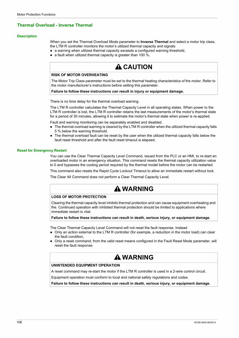
Motor Protection Functions
Thermal Overload - Inverse Thermal
Description
When you set the Thermal Overload Mode parameter to Inverse Thermal and select a motor trip class, the LTM R controller monitors the motor’s utilized thermal capacity and signals a warning when utilized thermal capacity exceeds a configured warning threshold, a fault when utilized thermal capacity is greater than 100 %.
There is no time delay for the thermal overload warning.
The LTM R controller calculates the Thermal Capacity Level in all operating states. When power to the LTM R controller is lost, the LTM R controller retains the last measurements of the motor’s thermal state for a period of 30 minutes, allowing it to estimate the motor’s thermal state when power is re-applied.
Fault and warning monitoring can be separately enabled and disabled. The thermal overload warning is cleared by the LTM R controller when the utilized thermal capacity falls
5 % below the warning threshold. The thermal overload fault can be reset by the user when the utilized thermal capacity falls below the
fault reset threshold and after the fault reset timeout is elapsed.
Reset for Emergency Restart
You can use the Clear Thermal Capacity Level Command, issued from the PLC or an HMI, to re-start an overloaded motor in an emergency situation. This command resets the thermal capacity utilization value to 0 and bypasses the cooling period required by the thermal model before the motor can be restarted.
This command also resets the Rapid Cycle Lockout Timeout to allow an immediate restart without lock.
The Clear All Command does not perform a Clear Thermal Capacity Level.
The Clear Thermal Capacity Level Command will not reset the fault response. Instead Only an action external to the LTM R controller (for example, a reduction in the motor load) can clear
the fault condition, Only a reset command, from the valid reset means configured in the Fault Reset Mode parameter, will
reset the fault response.
CAUTIONRISK OF MOTOR OVERHEATING
The Motor Trip Class parameter must be set to the thermal heating characteristics of the motor. Refer to the motor manufacturer’s instructions before setting this parameter.
Failure to follow these instructions can result in injury or equipment damage.
WARNINGLOSS OF MOTOR PROTECTION
Clearing the thermal capacity level inhibits thermal protection and can cause equipment overheating and fire. Continued operation with inhibited thermal protection should be limited to applications where immediate restart is vital.
Failure to follow these instructions can result in death, serious injury, or equipment damage.
WARNINGUNINTENDED EQUIPMENT OPERATION
A reset command may re-start the motor if the LTM R controller is used in a 2-wire control circuit.
Equipment operation must conform to local and national safety regulations and codes.
Failure to follow these instructions can result in death, serious injury, or equipment damage.
108 1672614EN 09/2014
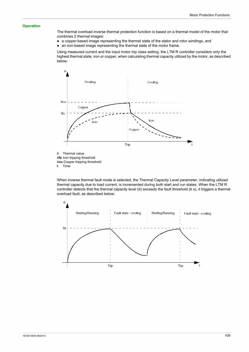
Motor Protection Functions
Operation
The thermal overload inverse thermal protection function is based on a thermal model of the motor that combines 2 thermal images: a copper-based image representing the thermal state of the stator and rotor windings, and an iron-based image representing the thermal state of the motor frame.
Using measured current and the input motor trip class setting, the LTM R controller considers only the highest thermal state, iron or copper, when calculating thermal capacity utilized by the motor, as described below:
θ Thermal valueθfe Iron tripping thresholdθcu Copper tripping thresholdt Time
When inverse thermal fault mode is selected, the Thermal Capacity Level parameter, indicating utilized thermal capacity due to load current, is incremented during both start and run states. When the LTM R controller detects that the thermal capacity level (θ) exceeds the fault threshold (θ s), it triggers a thermal overload fault, as described below:
1672614EN 09/2014 109

Motor Protection Functions
Functional Characteristics
The Thermal Overload inverse thermal functions include the following features: 1 motor trip class setting: Motor Trip Class
4 configurable thresholds: Motor Full Load Current Ratio (FLC1) Motor High Speed Full Load Current Ratio (FLC2) Thermal Overload Warning Threshold Thermal Overload Fault Reset Threshold
1 time delay: Fault Reset Timeout
2 function outputs: Thermal Overload Warning Thermal Overload Fault
2 counting statistics: Thermal Overload Faults Count Thermal Overload Warnings Count
1 setting for an external auxiliary motor cooling fan: Motor Aux Fan Cooled
1 measure of utilized thermal capacity: Thermal Capacity Level
NOTE: For LTM R controllers configured for 2-speed predefined operating mode, 2 fault thresholds are used: FLC1 and FLC2.
Block Diagram
Imax Maximum currentθmax Thermal capacity levelθs1 Thermal overload warning threshold
110 1672614EN 09/2014
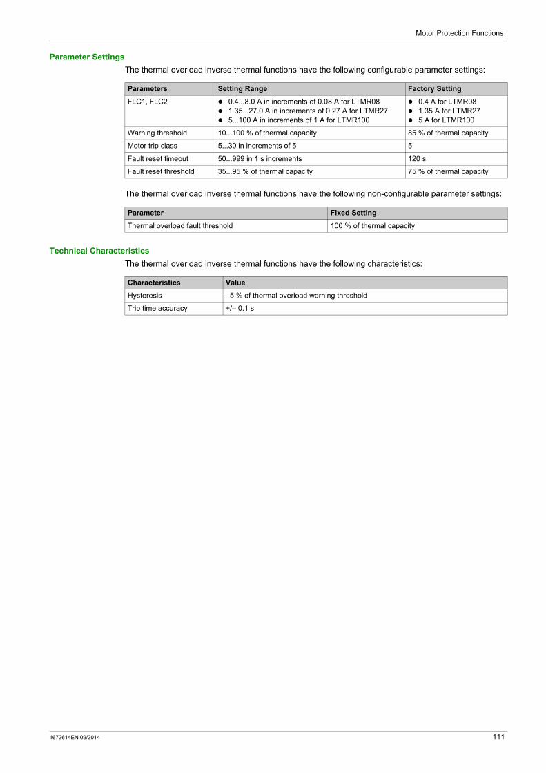
Motor Protection Functions
Parameter Settings
The thermal overload inverse thermal functions have the following configurable parameter settings:
The thermal overload inverse thermal functions have the following non-configurable parameter settings:
Technical Characteristics
The thermal overload inverse thermal functions have the following characteristics:
Parameters Setting Range Factory Setting
FLC1, FLC2 0.4...8.0 A in increments of 0.08 A for LTMR08 1.35...27.0 A in increments of 0.27 A for LTMR27 5...100 A in increments of 1 A for LTMR100
0.4 A for LTMR08 1.35 A for LTMR27 5 A for LTMR100
Warning threshold 10...100 % of thermal capacity 85 % of thermal capacity
Motor trip class 5...30 in increments of 5 5
Fault reset timeout 50...999 in 1 s increments 120 s
Fault reset threshold 35...95 % of thermal capacity 75 % of thermal capacity
Parameter Fixed Setting
Thermal overload fault threshold 100 % of thermal capacity
Characteristics Value
Hysteresis –5 % of thermal overload warning threshold
Trip time accuracy +/– 0.1 s
1672614EN 09/2014 111
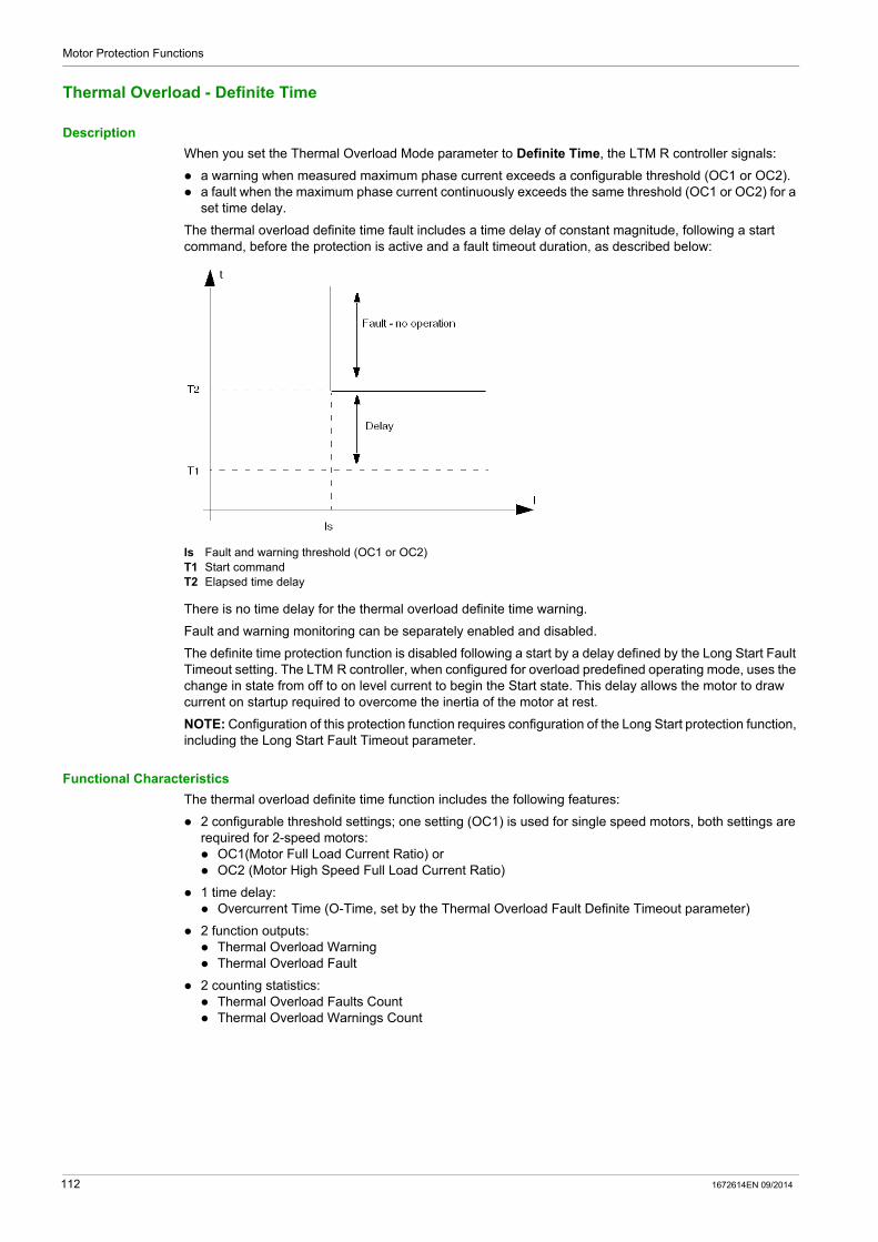
Motor Protection Functions
Thermal Overload - Definite Time
Description
When you set the Thermal Overload Mode parameter to Definite Time, the LTM R controller signals:
a warning when measured maximum phase current exceeds a configurable threshold (OC1 or OC2). a fault when the maximum phase current continuously exceeds the same threshold (OC1 or OC2) for a
set time delay.
The thermal overload definite time fault includes a time delay of constant magnitude, following a start command, before the protection is active and a fault timeout duration, as described below:
Is Fault and warning threshold (OC1 or OC2)T1 Start commandT2 Elapsed time delay
There is no time delay for the thermal overload definite time warning.
Fault and warning monitoring can be separately enabled and disabled.
The definite time protection function is disabled following a start by a delay defined by the Long Start Fault Timeout setting. The LTM R controller, when configured for overload predefined operating mode, uses the change in state from off to on level current to begin the Start state. This delay allows the motor to draw current on startup required to overcome the inertia of the motor at rest.
NOTE: Configuration of this protection function requires configuration of the Long Start protection function, including the Long Start Fault Timeout parameter.
Functional Characteristics
The thermal overload definite time function includes the following features:
2 configurable threshold settings; one setting (OC1) is used for single speed motors, both settings are required for 2-speed motors: OC1(Motor Full Load Current Ratio) or OC2 (Motor High Speed Full Load Current Ratio)
1 time delay: Overcurrent Time (O-Time, set by the Thermal Overload Fault Definite Timeout parameter)
2 function outputs: Thermal Overload Warning Thermal Overload Fault
2 counting statistics: Thermal Overload Faults Count Thermal Overload Warnings Count
112 1672614EN 09/2014

Motor Protection Functions
Block Diagram
I1 Phase 1 currentI2 Phase 2 currentI3 Phase 3 currentIs Fault and warning threshold (OC1 or OC2)T Fault timeout
Parameter Settings
The definite time thermal overload function has the following configurable parameter settings:
Technical Characteristics
The definite time thermal overload function has the following characteristics:
Example
The following diagram describes a definite time thermal overload fault:
OC Fault threshold (OC1 or OC2)
Parameters Setting Range Factory Setting
Fault threshold: Motor full load current ratio (OC1)
- or - Motor high speed full load current ratio (OC2)
5...100 % of FLCmax, in 1 % increments.Note: OC1 and OC2 settings can be set directly (in Amperes) in the Settings menu of an HMI, or in the Parameters tab of the TeSys T DTM.
5 % FLCmax
Thermal overload fault definite timeout (O-time or over-current time)
1...300 s in 1 s increments 10 s
Thermal overload warning threshold 20...800 % of OC in 1 % increments 80 % of OC
Long start fault timeout(1) (D-time) 1...200 s in 1 s increments 10 s
(1) The definite time thermal overload function requires the simultaneous use of the Long start motor protection function, both of which employ the Long start fault timeout setting.
Characteristics Value
Hysteresis –5 % of warning and fault thresholds
Trip time accuracy +/– 0.1 s
1672614EN 09/2014 113

Motor Protection Functions
Motor Temperature Sensor
Overview
The LTM R controller has 2 terminals—T1 and T2—that can be connected to a motor temperature sensing element to provide protection for motor windings by detecting high temperature conditions that could lead to damage or degradation.
These protections are activated when the Motor Temp Sensor Type parameter is set to one of the following settings:
PTC Binary (see page 115) PT100 (see page 117) PTC Analog (see page 119) NTC Analog (see page 121)
Only one of these motor protection sensing elements can be enabled at a time.
NOTE: Motor temperature sensor protection is based in ohms. PTC Binary protection thresholds are pre-set to IEC standards and are non-configurable. PTC Analog and NTC Analog protection functions may require that you scale the resistance value to the corresponding threshold level in degrees, based on the properties of the selected sensing element.
When a sensor type is changed, the LTM R controller’s motor temperature sensing configuration settings revert to their factory settings. If a sensor type is replaced with another sensor of the same type, the setting values are retained.
Parameter Settings
The motor temperature sensor function has the following configurable parameter settings, which apply to the selected motor temp sensor type:
Parameters Setting Range Factory Setting
Sensor type None PTC Binary PT100 PTC Analog NTC Analog
None
Fault enable Enable/Disable Disable
Warning enable Enable/Disable Disable
114 1672614EN 09/2014
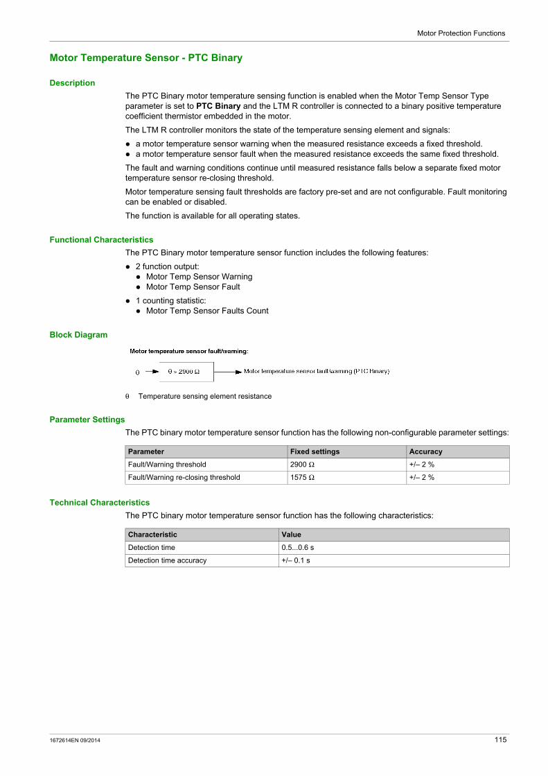
Motor Protection Functions
Motor Temperature Sensor - PTC Binary
Description
The PTC Binary motor temperature sensing function is enabled when the Motor Temp Sensor Type parameter is set to PTC Binary and the LTM R controller is connected to a binary positive temperature coefficient thermistor embedded in the motor.
The LTM R controller monitors the state of the temperature sensing element and signals:
a motor temperature sensor warning when the measured resistance exceeds a fixed threshold. a motor temperature sensor fault when the measured resistance exceeds the same fixed threshold.
The fault and warning conditions continue until measured resistance falls below a separate fixed motor temperature sensor re-closing threshold.
Motor temperature sensing fault thresholds are factory pre-set and are not configurable. Fault monitoring can be enabled or disabled.
The function is available for all operating states.
Functional Characteristics
The PTC Binary motor temperature sensor function includes the following features:
2 function output: Motor Temp Sensor Warning Motor Temp Sensor Fault
1 counting statistic: Motor Temp Sensor Faults Count
Block Diagram
θ Temperature sensing element resistance
Parameter Settings
The PTC binary motor temperature sensor function has the following non-configurable parameter settings:
Technical Characteristics
The PTC binary motor temperature sensor function has the following characteristics:
Parameter Fixed settings Accuracy
Fault/Warning threshold 2900 Ω +/– 2 %
Fault/Warning re-closing threshold 1575 Ω +/– 2 %
Characteristic Value
Detection time 0.5...0.6 s
Detection time accuracy +/– 0.1 s
1672614EN 09/2014 115
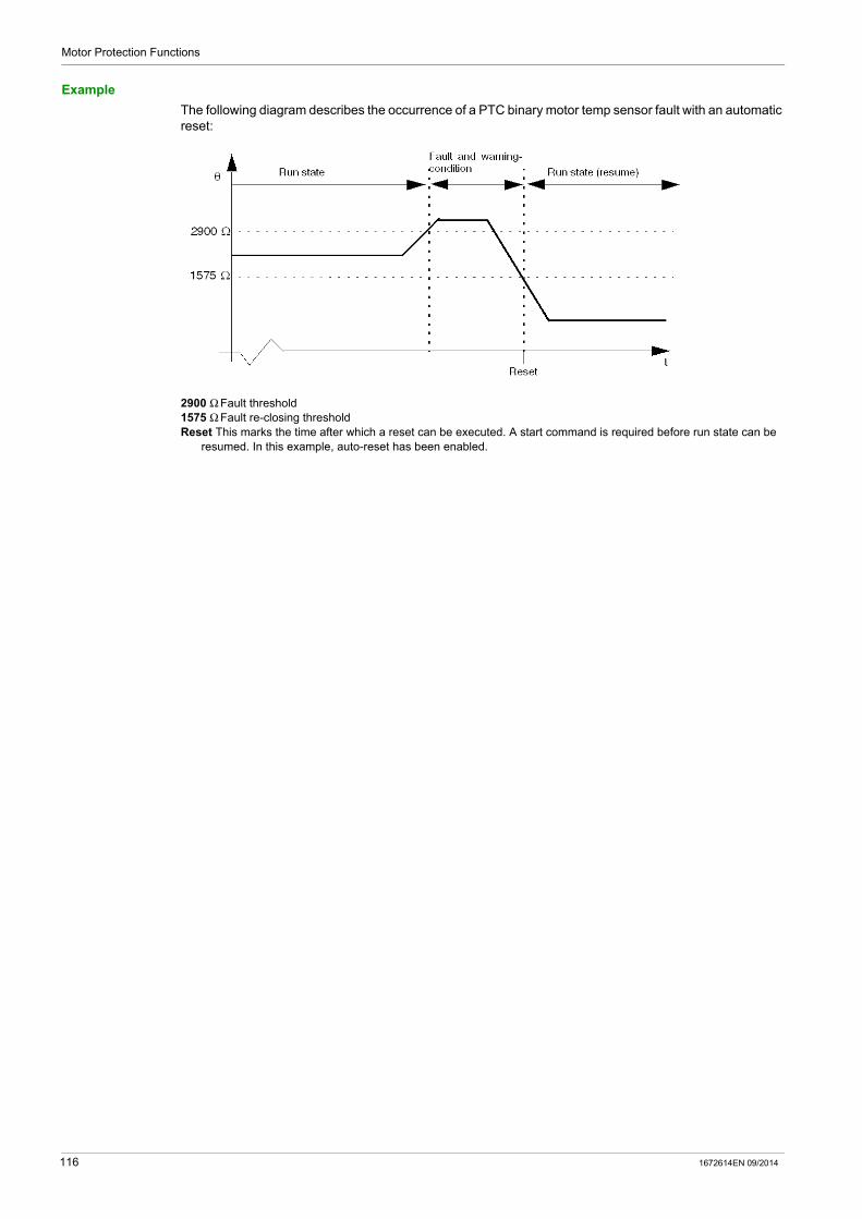
Motor Protection Functions
Example
The following diagram describes the occurrence of a PTC binary motor temp sensor fault with an automatic reset:
2900 Ω Fault threshold1575 Ω Fault re-closing thresholdReset This marks the time after which a reset can be executed. A start command is required before run state can be
resumed. In this example, auto-reset has been enabled.
116 1672614EN 09/2014
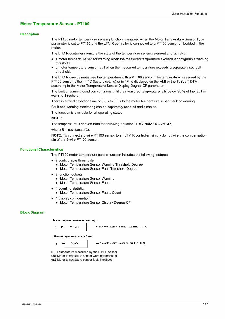
Motor Protection Functions
Motor Temperature Sensor - PT100
Description
The PT100 motor temperature sensing function is enabled when the Motor Temperature Sensor Type parameter is set to PT100 and the LTM R controller is connected to a PT100 sensor embedded in the motor.
The LTM R controller monitors the state of the temperature sensing element and signals:
a motor temperature sensor warning when the measured temperature exceeds a configurable warning threshold.
a motor temperature sensor fault when the measured temperature exceeds a separately set fault threshold.
The LTM R directly measures the temperature with a PT100 sensor. The temperature measured by the PT100 sensor, either in ° C (factory setting) or in ° F, is displayed on the HMI or the TeSys T DTM, according to the Motor Temperature Sensor Display Degree CF parameter:
The fault or warning condition continues until the measured temperature falls below 95 % of the fault or warning threshold.
There is a fixed detection time of 0.5 s to 0.6 s to the motor temperature sensor fault or warning.
Fault and warning monitoring can be separately enabled and disabled.
The function is available for all operating states.
NOTE:
The temperature is derived from the following equation: T = 2.6042 * R - 260.42,
where R = resistance (Ω).
NOTE: To connect a 3-wire PT100 sensor to an LTM R controller, simply do not wire the compensation pin of the 3-wire PT100 sensor.
Functional Characteristics
The PT100 motor temperature sensor function includes the following features:
2 configurable thresholds: Motor Temperature Sensor Warning Threshold Degree Motor Temperature Sensor Fault Threshold Degree
2 function outputs: Motor Temperature Sensor Warning Motor Temperature Sensor Fault
1 counting statistic: Motor Temperature Sensor Faults Count
1 display configuration: Motor Temperature Sensor Display Degree CF
Block Diagram
θ Temperature measured by the PT100 sensorθs1 Motor temperature sensor warning thresholdθs2 Motor temperature sensor fault threshold
1672614EN 09/2014 117

Motor Protection Functions
Parameter Settings
The PT100 motor temperature sensor function has the following configurable parameter settings:
Technical Characteristics
The PT100 motor temperature sensor function has the following characteristics:
Example
The following diagram describes a Motor temperature sensor PT100 fault with automatic reset and an active Run command:
θs2 Fault threshold θs3 Fault re-closing threshold (95% of fault threshold)
Parameters Setting Range Factory Setting
Fault threshold degree 0...200 ° C in 1 ° C increments 0 ° C
Warning threshold degree 0...200 ° C in 1 ° C increments 0 ° C
Motor temperature sensor display degree CF
° C (0)° F (1)
° C
Characteristic Value
Hysteresis –5 % of Warning threshold and Fault threshold
Detection time 0.5...0.6 s
Trip time accuracy +/–0.1 s
118 1672614EN 09/2014

Motor Protection Functions
Motor Temperature Sensor - PTC Analog
Description
The PTC Analog motor temperature sensing function is enabled when the Motor Temp Sensor Type parameter is set to PTC Analog and the LTM R controller is connected to an analog PTC thermistor embedded in the motor.
The LTM R controller monitors the state of the temperature sensing element and signals:
a motor temperature sensor warning when the measured resistance exceeds a configurable warning threshold.
a motor temperature sensor fault when the measured resistance exceeds a separately set fault threshold.
The fault or warning condition continues until the measured resistance falls below 95 % of the fault or warning threshold.
Fault and warning monitoring can be separately enabled and disabled.
The function is available for all operating states.
Functional Characteristics
The PTC Analog motor temperature sensor function includes the following features:
2 configurable thresholds: Motor Temp Sensor Warning Threshold Motor Temp Sensor Fault Threshold
2 function outputs: Motor Temp Sensor Warning Motor Temp Sensor Fault
1 counting statistic: Motor Temp Sensor Faults Count
Block Diagram
θ Temperature sensing element resistanceθs1 Motor temperature sensor warning thresholdθs2 Motor temperature sensor fault threshold
Parameter Settings
The PTC analog motor temperature sensor function has the following configurable parameter settings:
Technical Characteristics
The PTC analog motor temperature sensor function has the following characteristics:
Parameters Setting Range Factory Setting
Fault threshold 20...6500 Ω in 0.1 Ω increments 20 Ω
Warning threshold 20...6500 Ω in 0.1 Ω increments 20 Ω
Characteristic Value
Hysteresis –5 % of Warning threshold and Fault threshold
Detection time 0.5...0.6 s
Detection time accuracy +/–0.1 s
1672614EN 09/2014 119

Motor Protection Functions
Example
The following diagram describes a Motor temperature sensor PTC analog fault with automatic reset and an active Run command:
θs2 Fault threshold θs3 Fault re-closing threshold (95% of fault threshold)
120 1672614EN 09/2014

Motor Protection Functions
Motor Temperature Sensor - NTC Analog
Description
The NTC Analog motor temperature sensing function is enabled when the Motor Temp Sensor Type parameter is set to NTC Analog and the LTM R controller is connected to an analog NTC thermistor embedded in the motor.
The LTM R controller monitors the state of the temperature sensing element and signals:
a motor temperature sensor warning when the measured resistance falls below a configurable warning threshold.
a motor temperature sensor fault when the measured resistance falls below a separately set fault threshold.
The fault or warning condition continues until the measured resistance exceeds 105 % of the fault or warning threshold.
Fault and warning monitoring can be separately enabled and disabled.
The function is available for all operating states.
Functional Characteristics
The NTC Analog motor temperature sensor function includes the following features:
2 configurable thresholds: Warning Threshold Fault Threshold
2 function outputs: Motor Temp Sensor Warning Motor Temp Sensor Fault
1 counting statistic: Motor Temp Sensor Faults Count
Block Diagram
θ Temperature sensing element resistanceθs1 Motor temperature sensor warning thresholdθs2 Motor temperature sensor fault threshold
Parameter Settings
The NTC analog motor temperature sensor function has the following configurable parameter settings:
Technical Characteristics
The NTC analog motor temperature sensor function has the following characteristics:
Parameters Setting Range Factory Setting
Fault threshold 20...6500 Ω in 0.1 Ω increments 20 Ω
Warning threshold 20...6500 Ω in 0.1 Ω increments 20 Ω
Characteristics Value
Hysteresis + 5 % of Warning threshold and Fault thresholds
Detection time 0.5...0.6 s
Detection time accuracy +/– 0.1 s
1672614EN 09/2014 121

Motor Protection Functions
Example
The following diagram describes a Motor temperature sensor NTC analog fault with automatic reset:
θr2 Fault threshold θr3 Fault re-closing threshold (105% of fault threshold)
122 1672614EN 09/2014

Motor Protection Functions
Rapid Cycle Lockout
Description
The rapid cycle lockout function prevents potential harm to the motor caused by repetitive, successive inrush currents resulting from too little time between starts.
The rapid cycle lockout function provides a configurable timer, which begins its count when the LTM R controller detects On Level Current–defined as 20 % of FLC. At the same time the Rapid Cycle Lockout bit is set.
If the LTM R controller detects a Run command before the rapid cycle lockout has elapsed, the:
Rapid Cycle Lockout bit remains set LTM R controller ignores the Run command. It prevents the motor from restarting HMI device (if attached) displays "WAIT" LTM R controller Alarm LED flashes red 5 times per second, indicating the LTM R controller has
disabled motor outputs thereby preventing an undesirable condition caused by starting the motor LTM R controller monitors the wait time–if more than 1 timer is active, the LTM R controller reports the
minimum wait time before the longest timer elapses
On power loss, the LTM R controller saves the state of the lockout timer in non-volatile memory. When the LTM R controller next powers up, the timer restarts its count and again ignores Run commands until the timer completes the timeout.
Setting the Rapid Cycle Lockout Timeout parameter to 0 disables this function.
The Rapid Cycle Lockout Timeout setting can be edited when the LTM R controller is in its normal operating state. If an edit is made while the timer is counting, the edit is effective when the timer finishes counting.
This function has no warning and no fault.
NOTE: The Rapid Cycle Lockout function is not active when the overload operating mode is selected.
Functional Characteristics
The rapid cycle lockout function includes the following parameters:
1 time delay: Rapid Cycle Lockout Timeout
1 status bit: Rapid Cycle Lockout
In addition, the Rapid Cycle Lockout function:
disables motor outputs causes the LTM R Alarm LED to flash 5 times per second
Parameter Settings
The rapid cycle lockout function has the following parameters:
Technical Characteristics
The rapid cycle lockout function has the following characteristics:
Parameters Setting Range Factory Setting
Rapid cycle lockout timeout 0...9999 s in increments of 1 s 0 s
Characteristics Value
Trip time accuracy +/– 0.1 s or +/– 5%
1672614EN 09/2014 123

Motor Protection Functions
Example
124 1672614EN 09/2014

Motor Protection Functions
Current Motor Protection Functions
Section 3.3Current Motor Protection Functions
Overview
This section describes the current motor protection functions of the LTM R controller.
What Is in This Section?
This section contains the following topics:
Topic Page
Current Phase Imbalance 126
Current Phase Loss 129
Current Phase Reversal 131
Long Start 132
Jam 134
Undercurrent 136
Overcurrent 138
Ground Current 140
Internal Ground Current 141
External Ground Current 143
1672614EN 09/2014 125

Motor Protection Functions
Current Phase Imbalance
Description
The current phase imbalance function signals:
a warning when the current in any phase differs by more than a set percentage from the average current in all 3 phases.
a fault when the current in any phase differs by more than a separately set percentage from the average current in all 3 phases for a set period of time.
NOTE: Use this function to detect and guard against smaller current phase imbalances. For larger imbalances, in excess of 80 % of the average current in all 3 phases, use the current phase loss motor protection function.
This function has 2 adjustable fault time delays:
one applies to current imbalances occurring while the motor is in start state, and one applies to current imbalances occurring after startup while the motor is in run state
Both timers begin if the imbalance is detected in start state.
The function identifies the phase causing a current imbalance. If the maximum deviation from the 3 phase current average is the same for 2 phases, the function identifies both phases.
Fault and warning monitoring can be separately enabled and disabled.
The function applies only to 3-phase motors.
Functional Characteristics
The current phase imbalance function includes the following features:
2 thresholds: Warning Threshold Fault Threshold
2 fault time delays: Fault Timeout Starting Fault Timeout Running
2 function outputs: Current Phase Imbalance Warning Current Phase Imbalance Fault
1 counting statistic: Current Phase Imbalance Faults Count
3 indicators identifying the phase or phases with the highest current imbalance: L1 Current Highest Imbalance L2 Current Highest Imbalance L3 Current Highest Imbalance
CAUTIONRISK OF MOTOR OVERHEATING
The Current Phase Imbalance Fault Threshold must be properly set to protect the wiring and motor equipment from harm caused by motor overheating.
The setting you input must conform to national and local safety regulations and codes. Refer to the motor manufacturer’s instructions before setting this parameter.
Failure to follow these instructions can result in injury or equipment damage.
126 1672614EN 09/2014

Motor Protection Functions
Block Diagram
Current phase imbalance warning and fault:
I1 Phase 1 currentI2 Phase 2 currentI3 Phase 3 currentIimb Current imbalance ratio for 3-phaseIs1 Warning thresholdIs2 Fault thresholdT1 Fault timeout startingT2 Fault timeout running
Parameter Settings
The current phase imbalance function has the following parameters:
NOTE: A time of 0.7 second is added to the Fault timeout starting parameter to avoid nuisance tripping during the start phase.
Technical Characteristics
The current phase imbalance function has the following characteristics:
Parameters Setting Range Factory Setting
Fault enable Enable/Disable Enable
Fault timeout starting 0.2...20 s in 0.1 s increments 0.7 s
Fault timeout running 0.2...20 s in 0.1 s increments 5 s
Fault threshold 10...70 % of the calculated imbalance in 1% increments 10 %
Warning enable Enable/Disable Disable
Warning threshold 10...70 % of the calculated imbalance in 1% increments 10 %
Characteristics Value
Hysteresis –5 % of fault or warning threshold
Trip time accuracy +/–0.1 s or +/–5 %
1672614EN 09/2014 127
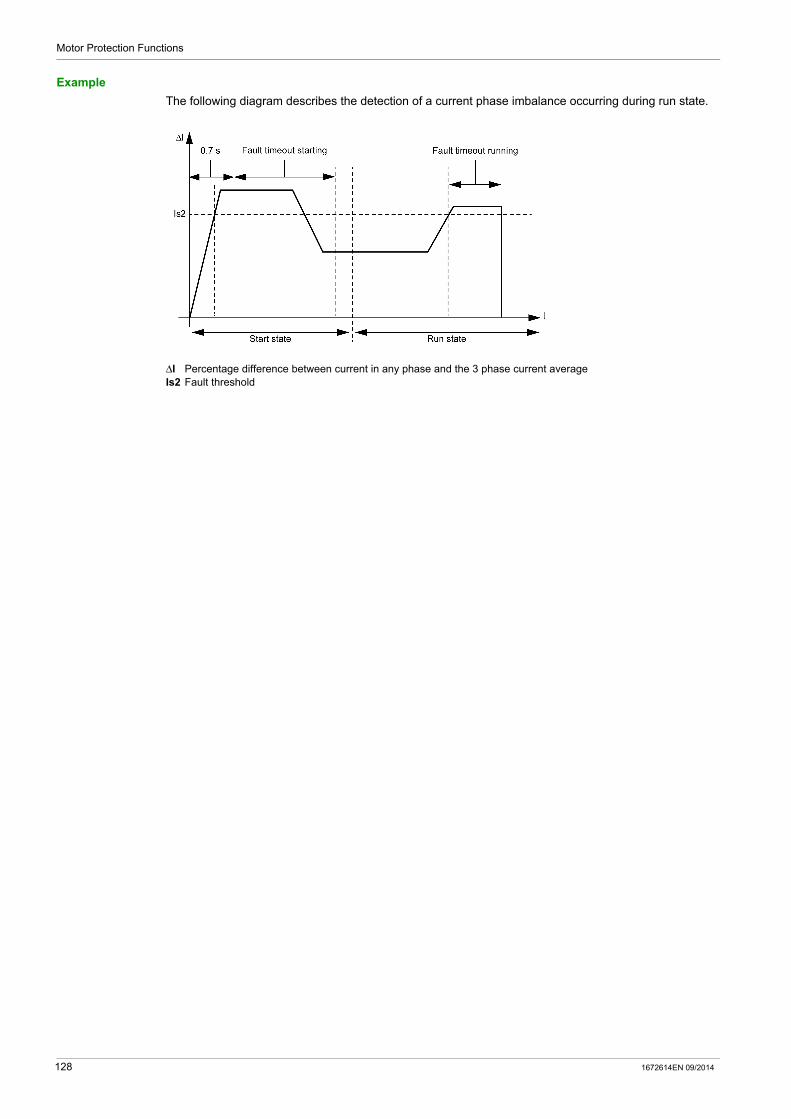
Motor Protection Functions
Example
The following diagram describes the detection of a current phase imbalance occurring during run state.
ΔI Percentage difference between current in any phase and the 3 phase current averageIs2 Fault threshold
128 1672614EN 09/2014

Motor Protection Functions
Current Phase Loss
Description
The current phase loss function signals:
a warning when the current in any phase differs by more than 80 % from the average current in all 3 phases.
a fault when the current in any phase differs by more than 80 % from the average current in all 3 phases for a set period of time.
NOTE: Use this function to detect and guard against large current phase imbalances, in excess of 80 % of the average current in all 3 phases. For smaller current imbalances, use the current phase imbalance motor protection function.
This function has a single adjustable fault time delay, which is applied when the motor is in start state or run state.
The function identifies the phase experiencing a current loss. If the maximum deviation from the 3 phase current average is the same for 2 phases, the function identifies both phases.
Fault and warning monitoring can be separately enabled and disabled.
The function applies only to 3-phase motors.
Functional Characteristics
The current phase loss function includes the following features:
1 fixed fault and warning threshold equal to 80 % of the 3 phase average current. 1 fault time delay: Current Phase Loss Timeout
2 function outputs: Current Phase Loss Warning Current Phase Loss Fault
1 counting statistic: Current Phase Loss Faults Count
3 indicators identifying the phase or phases experiencing the current loss: L1 Current loss L2 Current loss L3 Current loss
Block Diagram
I1 Phase 1 currentI2 Phase 2 currentI3 Phase 3 currentLn Line current number or numbers with the greatest deviation from IavgIavg 3 phase current averageT Fault timeout
1672614EN 09/2014 129

Motor Protection Functions
Parameter Settings
The current phase loss function has the following configurable parameters:
NOTE: A time of 0.7 second is added to the Fault timeout parameter to avoid nuisance tripping during the start phase.
Technical Characteristics
The current phase loss function has the following characteristics:
Example
The following diagram describes the occurrence of a current phase loss fault of a motor in run state.
Δ%I Percentage difference between current in any phase and the 3 phase current average
Parameters Setting Range Factory Setting
Fault enable Enable/Disable Enable
Timeout 0.1...30 s in 0.1 s increments 3 s
Warning enable Enable/Disable Enable
Characteristics Value
Hysteresis 75 % of the 3 phase average current
Trip time accuracy +/–0.1 s or +/–5 %
130 1672614EN 09/2014
Motor Protection Functions
Current Phase Reversal
Description
The current phase reversal function signals a fault when it detects that the current phases of a 3-phase motor are out of sequence with the Motor Phases Sequence parameter, ABC or ACB.
NOTE: When the LTM R controller is connected to an expansion module, phase reversal protection is based on voltage phase sequence before the motor starts, and on current phase sequence after the motor starts.
This function:
is active when the motor is in start state or run state applies only to 3-phase motors has no warning and no timer.
This function can be enabled or disabled.
Functional Characteristics
The current phase reversal function adds to one counting statistic, Wiring Faults Count.
Parameter Settings
The current phase reversal function has the following configurable parameters:
Technical Characteristics
The current phase reversal function has the following characteristics:
Parameters Setting Range Factory Setting
Fault enable Enable/Disable Disable
Phase sequence A-B-C A-C-B
A-B-C
Characteristic Value
Trip time at motor startup within 0.2 s of motor startup
Trip time accuracy +/–0.1 s or +/–5%
1672614EN 09/2014 131
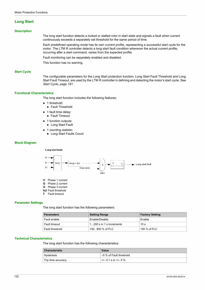
Motor Protection Functions
Long Start
Description
The long start function detects a locked or stalled rotor in start state and signals a fault when current continuously exceeds a separately set threshold for the same period of time.
Each predefined operating mode has its own current profile, representing a successful start cycle for the motor. The LTM R controller detects a long start fault condition whenever the actual current profile, occurring after a start command, varies from the expected profile.
Fault monitoring can be separately enabled and disabled.
This function has no warning.
Start Cycle
The configurable parameters for the Long Start protection function, Long Start Fault Threshold and Long Start Fault Timeout, are used by the LTM R controller in defining and detecting the motor’s start cycle. See Start Cycle, page 181.
Functional Characteristics
The long start function includes the following features:
1 threshold: Fault Threshold
1 fault time delay: Fault Timeout
1 function outputs: Long Start Fault
1 counting statistic: Long Start Faults Count
Block Diagram
I1 Phase 1 currentI2 Phase 2 currentI3 Phase 3 currentIs2 Fault thresholdT Fault timeout
Parameter Settings
The long start function has the following parameters:
Technical Characteristics
The long start function has the following characteristics:
Parameters Setting Range Factory Setting
Fault enable Enable/Disable Enable
Fault timeout 1...200 s in 1 s increments 10 s
Fault threshold 100...800 % of FLC 100 % of FLC
Characteristic Value
Hysteresis –5 % of Fault threshold
Trip time accuracy +/– 0.1 s or +/– 5 %
132 1672614EN 09/2014

Motor Protection Functions
Example
The following diagram describes the occurrence of a single threshold cross long start fault:
Is2 Long start fault threshold
1672614EN 09/2014 133

Motor Protection Functions
Jam
Description
The jam function detects a locked rotor during run state and signals:
a warning when current in any phase exceeds a set threshold, after the motor has reached run state. a fault when current in any phase continuously exceeds a separately set threshold for a specified period
of time, after the motor has reached run state.
The jam function is triggered when the motor is jammed during run state and stops, or is suddenly overloaded and draws excessive current.
Fault and warning monitoring can be separately enabled and disabled.
Functional Characteristics
The jam function includes the following features:
2 thresholds: Warning Threshold Fault Threshold
1 fault time delay: Fault Timeout
2 function outputs: Jam Warning Jam Fault
1 counting statistic: Jam Faults Count
Block Diagram
Jam warning and fault:
I1 Phase 1 currentI2 Phase 2 currentI3 Phase 3 currentIs1 Warning thresholdIs2 Fault thresholdT Fault timeout
Parameter Settings
The jam function has the following parameters:
Parameters Setting Range Factory Setting
Fault enable Enable/Disable Enable
Fault timeout 1...30 s in 1 s increments 5 s
Fault threshold 100...800 % of FLC in 1 % increments 200 % of FLC
Warning enable Enable/Disable Disable
Warning threshold 100...800 % of FLC in 1 % increments 200 % of FLC
134 1672614EN 09/2014
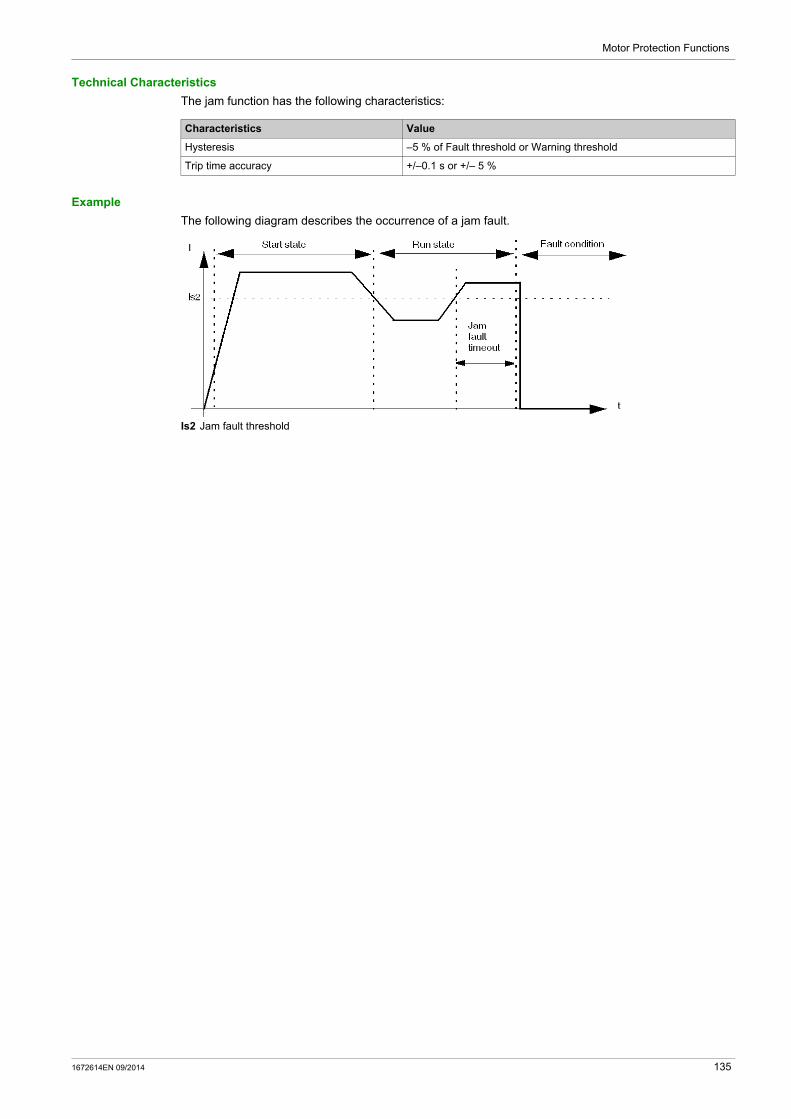
Motor Protection Functions
Technical Characteristics
The jam function has the following characteristics:
Example
The following diagram describes the occurrence of a jam fault.
Is2 Jam fault threshold
Characteristics Value
Hysteresis –5 % of Fault threshold or Warning threshold
Trip time accuracy +/–0.1 s or +/– 5 %
1672614EN 09/2014 135

Motor Protection Functions
Undercurrent
Description
The undercurrent function signals:
a warning when the 3-phase Average Current falls below a set threshold, after the motor has reached run state.
a fault when the 3-phase Average Current falls and remains below a separately set threshold for a set period of time, after the motor has reached run state.
The undercurrent function is triggered when the motor current falls below a defined level for the driven load, for example, if a drive belt or shaft has broken, allowing the motor to run free rather than under load. This function has a single fault time delay. Fault and warning monitoring can be separately enabled and disabled.
Functional Characteristics
The undercurrent function includes the following features:
2 thresholds: Warning Threshold Fault Threshold
1 fault time delay: Fault Timeout
2 function outputs: Undercurrent Warning Undercurrent Fault
1 counting statistic: Undercurrent Faults Count
Block Diagram
Undercurrent warning and fault:
Iavg Average currentIs1 Warning thresholdIs2 Fault thresholdT Fault timer delay
Parameter Settings
The undercurrent function has the following parameters:
Parameters Setting Range Factory Setting
Fault enable Enable/Disable Disable
Fault timeout 1...200 s in 1 s increments 1 s
Fault threshold 30...100 % of FLC in 1 % increments 50 % of FLC
Warning enable Enable/Disable Disable
Warning threshold 30...100 % of FLC in 1 % increments 50 % of FLC
136 1672614EN 09/2014

Motor Protection Functions
Technical Characteristics
The undercurrent function has the following characteristics:
Example
The following diagram describes the occurrence of an undercurrent fault.
Is2 Undercurrent fault threshold
Characteristics Value
Hysteresis –5 % of Fault threshold or Warning threshold
Trip time accuracy +/– 0.1 s or +/- 5 %
1672614EN 09/2014 137

Motor Protection Functions
Overcurrent
Description
The overcurrent function signals:
a warning when current in a phase exceeds a set threshold, after the motor has reached run state. a fault when current in a phase continuously exceeds a separately set threshold for a set period of time,
after the motor has reached run state.
The overcurrent function can be triggered when the equipment is overloaded or a process condition is detected causing current to increase beyond the set threshold. This function has a single fault time delay. Fault and warning monitoring can be separately enabled and disabled.
Functional Characteristics
The overcurrent function includes the following features:
2 thresholds: Warning Threshold Fault Threshold
1 fault time delay: Fault Timeout
2 function outputs: Overcurrent Warning Overcurrent Fault
1 counting statistic: Overcurrent Faults Count
Block Diagram
I1 Phase 1 currentI2 Phase 2 currentI3 Phase 3 currentIs1 Warning thresholdIs2 Fault thresholdT Fault timeout
Parameter Settings
The overcurrent function has the following parameters:
Parameters Setting Range Factory Setting
Fault enable Enable/Disable Disable
Fault timeout 1...250 s in 1 s increments 10 s
Fault threshold 30...800 % of FLC in 1 % increments 200 % of FLC
Warning enable Enable/Disable Disable
Warning threshold 30...800 % of FLC in 1 % increments 200 % of FLC
138 1672614EN 09/2014
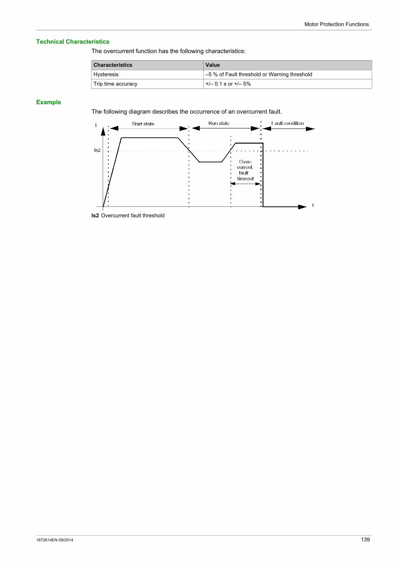
Motor Protection Functions
Technical Characteristics
The overcurrent function has the following characteristics:
Example
The following diagram describes the occurrence of an overcurrent fault.
Is2 Overcurrent fault threshold
Characteristics Value
Hysteresis –5 % of Fault threshold or Warning threshold
Trip time accuracy +/– 0.1 s or +/– 5%
1672614EN 09/2014 139

Motor Protection Functions
Ground Current
Overview
The LTM R controller can be configured to detect ground current:
internally, by summing the 3-phase current signals from the secondary of the internal current transformers (see page 141).
externally, by measuring the current delivered by the secondary of an external ground fault current transformer (see page 143).
Use the Ground Current Mode parameter to select either internal or external ground fault protection. Only one of these ground current mode settings can be activated at a time.
Parameter Settings
The ground current protection function has the following configurable parameter settings, which apply to both internal and external ground current protection:
Parameters Setting Range Factory Setting
Ground current mode Internal External
Internal
Fault enable Enable/Disable Enable
Warning enable Enable/Disable Enable
Ground fault disabled while starting Enable/Disable Enable
140 1672614EN 09/2014

Motor Protection Functions
Internal Ground Current
Description
The internal ground current function is enabled when the Ground Current Mode parameter is set to Internal and disabled when set to External.
The internal ground current function sums the current readings from the secondary of the internal current transformers and signals:
a warning when the summed current exceeds a set threshold. a fault when the summed current continuously exceeds a separately set threshold for a set period of
time.
The internal ground current function has a single fault time delay.
The internal ground current function can be enabled when the motor is in ready state, start state, or run state. This function can be configured so that it is disabled during start state, and enabled only during ready state and run state.
Fault and warning monitoring can be separately enabled and disabled.
Functional Characteristics
The internal ground current function includes the following features:
1 measure of ground current in amperes: Ground Current
1 measure of ground current as a % of FLCmin: Ground Current Ratio
2 thresholds: Warning Threshold Fault Threshold
1 fault time delay: Fault Timeout
2 function outputs: Internal Ground Current Warning Internal Ground Current Fault
1 counting statistic: Ground Current Faults Count
DANGERIMPROPER FAULT DETECTION
Internal ground current function will not protect people from harm caused by ground current.
Ground fault thresholds must be set to protect the motor and related equipment.
Ground fault settings must conform to national and local safety regulations and codes.
Failure to follow these instructions will result in death or serious injury.
1672614EN 09/2014 141
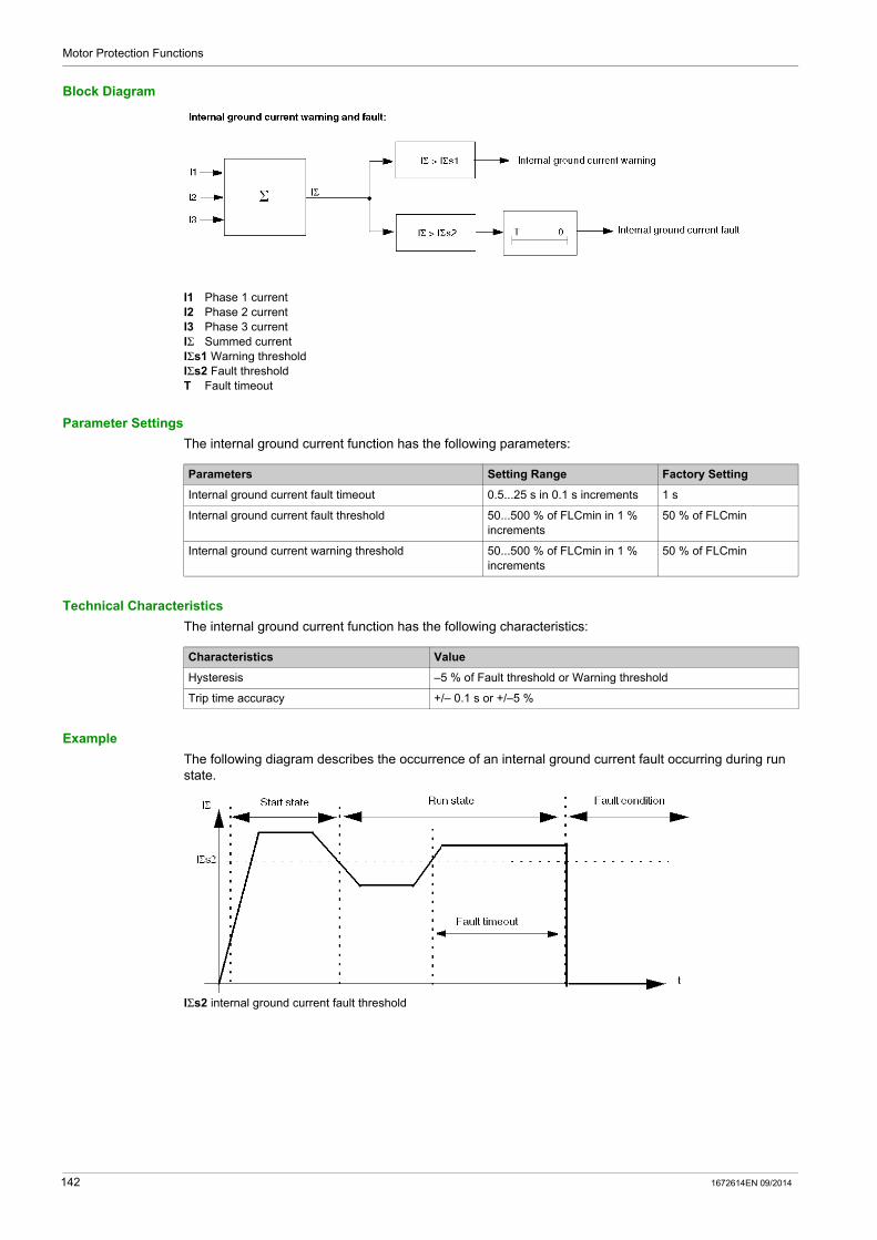
Motor Protection Functions
Block Diagram
I1 Phase 1 currentI2 Phase 2 currentI3 Phase 3 currentIΣ Summed currentIΣs1 Warning thresholdIΣs2 Fault thresholdT Fault timeout
Parameter Settings
The internal ground current function has the following parameters:
Technical Characteristics
The internal ground current function has the following characteristics:
Example
The following diagram describes the occurrence of an internal ground current fault occurring during run state.
IΣs2 internal ground current fault threshold
Parameters Setting Range Factory Setting
Internal ground current fault timeout 0.5...25 s in 0.1 s increments 1 s
Internal ground current fault threshold 50...500 % of FLCmin in 1 % increments
50 % of FLCmin
Internal ground current warning threshold 50...500 % of FLCmin in 1 % increments
50 % of FLCmin
Characteristics Value
Hysteresis –5 % of Fault threshold or Warning threshold
Trip time accuracy +/– 0.1 s or +/–5 %
142 1672614EN 09/2014

Motor Protection Functions
External Ground Current
Description
The external ground current function is enabled when:
the Ground Current Mode parameter is set to External, and a current transformation ratio is set.
When Ground Current Mode is set to Internal, the external ground current function is disabled.
The LTM R controller has 2 terminals—Z1 and Z2—that can be connected to an external ground current transformer. The external ground current function measures ground current delivered by the secondary of the external current transformer and signals:
a warning when the delivered current exceeds a set threshold. a fault when the delivered current continuously exceeds a separately set threshold for a set period of
time.
The external ground current function has a single fault time delay.
The external ground current function can be enabled when the motor is in ready state, start state, or run state. This function can be configured so that it is disabled only during start state, and enabled during ready state and run state.
Fault and warning monitoring can be separately enabled and disabled.
Functional Characteristics
The external ground current function includes the following features:
1 measure of ground current in amperes: Ground Current
2 thresholds: Warning Threshold Fault Threshold
1 fault time delay: Fault Timeout
2 function outputs: External Ground Current Warning External Ground Current Fault
1 counting statistic: Ground Current Faults Count
Block Diagram
Igr Ground current from external ground CTIgr s1 Warning thresholdIgr s2 Fault thresholdT Fault timeout
DANGERIMPROPER FAULT DETECTION
External ground current function will not protect people from harm caused by ground current.
Ground fault thresholds must be set to protect the motor and related equipment.
Ground fault settings must conform to national and local safety regulations and codes.
Failure to follow these instructions will result in death or serious injury.
1672614EN 09/2014 143
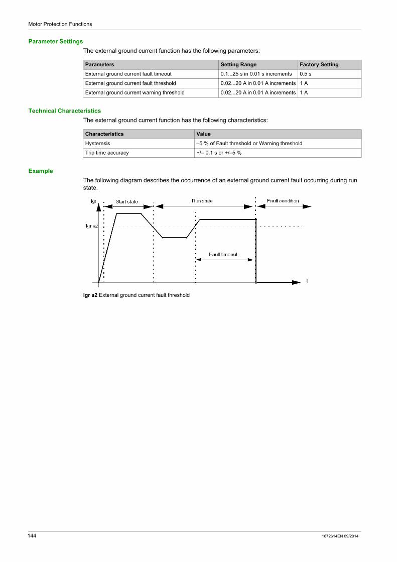
Motor Protection Functions
Parameter Settings
The external ground current function has the following parameters:
Technical Characteristics
The external ground current function has the following characteristics:
Example
The following diagram describes the occurrence of an external ground current fault occurring during run state.
Igr s2 External ground current fault threshold
Parameters Setting Range Factory Setting
External ground current fault timeout 0.1...25 s in 0.01 s increments 0.5 s
External ground current fault threshold 0.02...20 A in 0.01 A increments 1 A
External ground current warning threshold 0.02...20 A in 0.01 A increments 1 A
Characteristics Value
Hysteresis –5 % of Fault threshold or Warning threshold
Trip time accuracy +/– 0.1 s or +/–5 %
144 1672614EN 09/2014
Motor Protection Functions
Voltage Motor Protection Functions
Section 3.4Voltage Motor Protection Functions
Overview
This section describes the voltage motor protection functions provided by the LTM R controller.
What Is in This Section?
This section contains the following topics:
Topic Page
Voltage Phase Imbalance 146
Voltage Phase Loss 149
Voltage Phase Reversal 151
Undervoltage 152
Overvoltage 154
Voltage Dip Management 156
Load Shedding 157
Automatic Restart 159
1672614EN 09/2014 145

Motor Protection Functions
Voltage Phase Imbalance
Description
The voltage phase imbalance function signals:
a warning when the voltage in any composed phase differs by more than a set percentage from the average voltage in all 3 phases
a fault when the voltage in any composed phase differs by more than a separately set percentage from the average voltage in all 3 phases for a set period of time
NOTE: A composed phase is the combined measure of 2 phases: L1 + L2, L2 + L3, or L3 + L1.
This function: is active when the LTM R controller is connected to an expansion module is active when the average voltage is between 50 % and 120 % of the nominal voltage is available when the motor is in ready state, start state and run state applies only to 3-phase motors
This function has 2 adjustable fault time delays: one applies to voltage imbalances occurring while the motor is in start state, and one applies to voltage imbalances occurring while the motor is in run state, or when the long start time
duration expires
Both timers begin if the imbalance is detected in start state.
NOTE: Use this function to detect and guard against smaller voltage phase imbalances. For larger imbalances, in excess of 40 % of the average voltage in all 3 phases, use the voltage phase loss motor protection function.
Fault and warning monitoring can be separately enabled and disabled.
Functional Characteristics
The voltage phase imbalance function includes the following features:
2 thresholds: Warning Threshold Fault Threshold
2 fault time delays: Fault Timeout Starting Fault Timeout Running
2 function outputs: Voltage Phase Imbalance Warning Voltage Phase Imbalance Fault
1 counting statistic: Voltage Phase Imbalance Faults Count
3 indicators identifying the phase with the highest voltage imbalance: L1-L2 Highest Imbalance L2-L3 Highest Imbalance L3-L1 Highest Imbalance
146 1672614EN 09/2014

Motor Protection Functions
Block Diagram
V1 L1-L2 voltageV2 L2-L3 voltageV3 L3-L1 voltageLn Line number or numbers with greatest deviation from VavgVs1 Warning thresholdVs2 Fault thresholdVavg 3 phase voltage averageT1 Fault timeout starting T2 Fault timeout running
Parameter Settings
The voltage phase imbalance function has the following parameters:
Technical Characteristics
The voltage phase imbalance function has the following characteristics:
Parameters Setting Range Factory Setting
Fault enable Enable/Disable Disable
Fault timeout starting 0.2...20 s in 0.1 s increments 0.7 s
Fault timeout running 0.2...20 s in 0.1 s increments 2 s
Fault threshold 3...15 % of the calculated imbalance in 1 % increments
10 %
Warning enable Enable/Disable Disable
Warning threshold 3...15 % of the calculated imbalance in 1 % increments
10 %
Characteristics Value
Hysteresis –5 % of Fault threshold or Warning threshold
Trip time accuracy +/– 0.1 s or +/– 5 %
1672614EN 09/2014 147
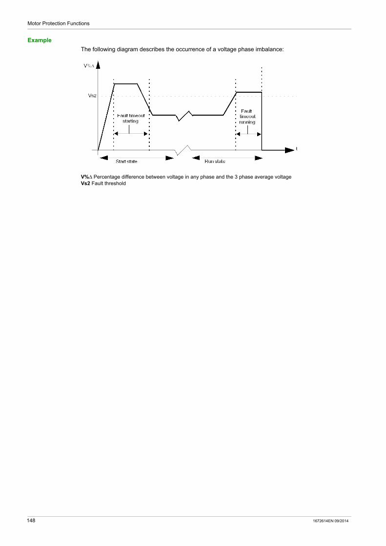
Motor Protection Functions
Example
The following diagram describes the occurrence of a voltage phase imbalance:
V%Δ Percentage difference between voltage in any phase and the 3 phase average voltageVs2 Fault threshold
148 1672614EN 09/2014

Motor Protection Functions
Voltage Phase Loss
Description
The voltage phase loss function is based on the Voltage Phase Imbalance function and signals:
a warning when the voltage in any phase differs by more than a 38 % from the average voltage in all 3 phases.
a fault when the voltage in any phase differs by more than 38 % from the average voltage in all 3 phases for a set period of time.
This function: is active when the LTM R controller is connected to an expansion module is active when the average voltage is between 50 % and 120 % of the nominal voltage is available when the motor is in ready state, start state or run state applies only to 3-phase motors
This function has a single adjustable fault time delay.
NOTE: Use this function to detect and guard against large voltage phase imbalances, in excess of 40 % of the average voltage in all 3 phases. For smaller voltage imbalances, use the voltage phase imbalance motor protection function.
The function identifies the phase experiencing a voltage loss. If the maximum deviation from the 3 phase voltage average is the same for 2 phases, the function identifies both phases.
Fault and warning monitoring can be separately enabled and disabled.
Functional Characteristics
The voltage phase loss function includes the following features:
A fixed fault and warning threshold equal to 38 % of the 3 phase average voltage. A single, adjustable fault time delay: Voltage Phase Loss Timeout
2 function outputs: Voltage Phase Loss Warning Voltage Phase Loss Fault
1 counting statistic: Voltage Phase Loss Faults Count
3 indicators identifying the phase experiencing the voltage loss: L1-L2 Voltage loss L2-L3 Voltage loss L3-L1 Voltage loss
Block Diagram
V1 L1-L2 voltageV2 L2-L3 voltageV3 L3-L1 voltageLn Line voltage number or numbers with the greatest deviation from VavgVavg 3 phase average voltageT Fault timeout
1672614EN 09/2014 149

Motor Protection Functions
Parameter Settings
The voltage phase loss function has the following configurable parameters:
Technical Characteristics
The voltage phase loss function has the following characteristics:
Example
The following diagram describes the occurrence of a voltage phase loss fault of a motor in run state:
ΔV% Percentage difference between voltage in any phase and the 3 phase average voltage
Parameters Setting Range Factory Setting
Fault enable Enable/Disable Enable
Fault timeout 0.1...30 s in 0.1 s increments 3 s
Warning enable Enable/Disable Enable
Characteristics Value
Hysteresis 45 % of the 3 phase average voltage
Trip time accuracy +/– 0.1 s or +/– 5%
150 1672614EN 09/2014

Motor Protection Functions
Voltage Phase Reversal
Description
The voltage phase reversal function signals a fault when it detects that the voltage phases of a 3-phase motor are out of sequence, usually indicating a wiring error. Use the Motor Phases Sequence parameter to configure the direction, ABC or ACB, in which the motor will turn.
This function: is available when the LTM R controller is connected to an expansion module is active when the average voltage is between 50 % and 120 % of the nominal voltage is available when the motor is in ready state, start state and run state applies only to 3-phase motors has no warning and no timer
This function can be enabled or disabled.
Functional Characteristics
The voltage phase reversal function adds one counting statistic, Wiring Faults Count.
Parameter Settings
The voltage phase reversal function has the following configurable parameters:
Technical Characteristics
The voltage phase reversal function has the following characteristics:
Parameters Setting Range Factory Setting
Fault enable Enable/Disable Disable
Motor phases sequence A-B-C A-C-B
A-B-C
Characteristics Value
Trip time within 0.2 s
Trip time accuracy +/– 0.1 s
1672614EN 09/2014 151

Motor Protection Functions
Undervoltage
Description
The undervoltage function signals:
a warning when voltage in a phase falls below a set threshold. a fault when voltage in a phase falls and remains below a separately set threshold for a set period of
time.
This function has a single fault time delay. Both the fault and warning thresholds are defined as a percentage of the Motor Nominal Voltage (Vnom) parameter setting.
The undervoltage function is available only in ready state and run state, when the LTM R controller is connected to an expansion module.
Fault and warning monitoring can be separately enabled and disabled.
Functional Characteristics
The undervoltage function includes the following features:
2 thresholds: Warning Threshold Fault Threshold
1 fault time delay: Fault Timeout
2 function outputs: Undervoltage Warning Undervoltage Fault
1 counting statistic: Undervoltage Faults Count
Block Diagram
V1 L1-L2 voltageV2 L2-L3 voltageV3 L3-L1 voltageVs1 Warning thresholdVs2 Fault thresholdT Fault timeout
152 1672614EN 09/2014

Motor Protection Functions
Parameter Settings
The undervoltage function has the following parameters:
Technical Characteristics
The undervoltage function has the following characteristics:
Example
The following diagram describes the occurrence of a undervoltage fault.
Vs2 Undervoltage fault threshold
Parameters Setting Range Factory Setting
Fault enable Enable/Disable Disable
Fault timeout 0.2...25 s in 0.1 s increments 3 s
Fault threshold 70...99 % of Motor nominal voltage in 1 % increments 85 %
Warning enable Enable/Disable Disable
Warning threshold 70...99 % of Motor nominal voltage in 1 % increments 85 %
Characteristics Value
Hysteresis -5 % of Fault threshold or Warning threshold
Trip time accuracy +/– 0.1 s or +/– 5 %
1672614EN 09/2014 153
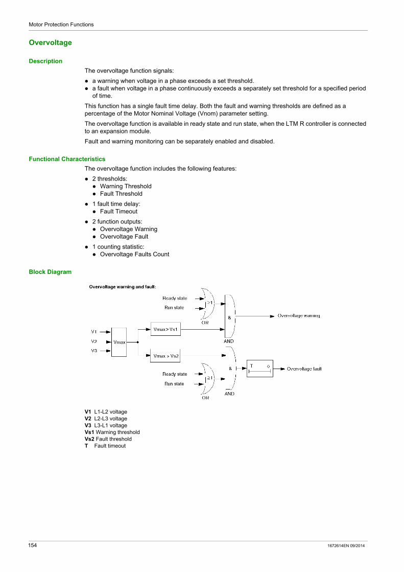
Motor Protection Functions
Overvoltage
Description
The overvoltage function signals:
a warning when voltage in a phase exceeds a set threshold. a fault when voltage in a phase continuously exceeds a separately set threshold for a specified period
of time.
This function has a single fault time delay. Both the fault and warning thresholds are defined as a percentage of the Motor Nominal Voltage (Vnom) parameter setting.
The overvoltage function is available in ready state and run state, when the LTM R controller is connected to an expansion module.
Fault and warning monitoring can be separately enabled and disabled.
Functional Characteristics
The overvoltage function includes the following features:
2 thresholds: Warning Threshold Fault Threshold
1 fault time delay: Fault Timeout
2 function outputs: Overvoltage Warning Overvoltage Fault
1 counting statistic: Overvoltage Faults Count
Block Diagram
V1 L1-L2 voltageV2 L2-L3 voltageV3 L3-L1 voltageVs1 Warning thresholdVs2 Fault thresholdT Fault timeout
154 1672614EN 09/2014
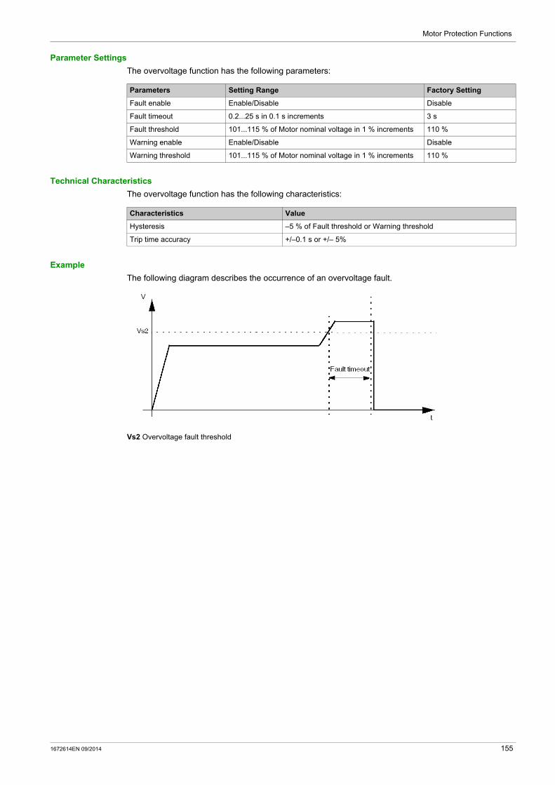
Motor Protection Functions
Parameter Settings
The overvoltage function has the following parameters:
Technical Characteristics
The overvoltage function has the following characteristics:
Example
The following diagram describes the occurrence of an overvoltage fault.
Vs2 Overvoltage fault threshold
Parameters Setting Range Factory Setting
Fault enable Enable/Disable Disable
Fault timeout 0.2...25 s in 0.1 s increments 3 s
Fault threshold 101...115 % of Motor nominal voltage in 1 % increments 110 %
Warning enable Enable/Disable Disable
Warning threshold 101...115 % of Motor nominal voltage in 1 % increments 110 %
Characteristics Value
Hysteresis –5 % of Fault threshold or Warning threshold
Trip time accuracy +/–0.1 s or +/– 5%
1672614EN 09/2014 155

Motor Protection Functions
Voltage Dip Management
Overview
When a voltage dip is detected, the LTM R can perform 2 different functions to shed and reconnect automatically the load: Load shedding (see page 157) Automatic restart (see page 159)
Selection is done via the Voltage dip mode parameter:
Load Shedding and Automatic Restart functions exclude each other.
If Voltage dip mode is... Then...
0 nothing happens
1 load shedding function is enabled
2 automatic restart function is enabled
156 1672614EN 09/2014

Motor Protection Functions
Load Shedding
Description
The LTM R controller provides load shedding, which you can use to deactivate non-critical loads if voltage level is substantially reduced. For example, use load shedding when power is transferred from a main utility supply to a backup generator system, where the backup generator system can supply power only to a limited number of critical loads.
The LTM R only monitors load shedding when Load Shedding is selected.
With the load shedding function enabled, the LTM R controller monitors the average phase voltage and: reports a load shedding condition and stops the motor when voltage falls below a configurable Voltage
dip threshold and stays below the threshold for the duration of a configurable load shedding timer, clears the load shedding condition when voltage rises above a configurable Voltage dip restart threshold
and remains above the threshold for the duration of a configurable Load shedding restart timer.
When the LTM R controller clears the load shedding condition: in 2-wire (maintained) configuration, it issues a Run command to re-start the motor, in 3-wire (impulse) configuration, it does not automatically re-start the motor.
In Overload motor operating mode, load shedding conditions do not affect O.1 and O.2 operating states.
In Independent motor operating mode, load shedding conditions do not affect O.2 state.
If your application includes another device that externally provides load shedding, the LTM R controller’s load shedding function should not be enabled.
All voltage dip thresholds and timers can be adjusted when the LTM R controller is in its normal operating state. When a load shedding timer is counting at the time it is adjusted, the new duration time does not become effective until the timer expires.
This function is available only when your application includes an LTM E expansion module.
Functional Characteristics
The load shedding function includes the following features:
2 thresholds: Voltage Dip Threshold Voltage Dip Restart Threshold
2 time delays: Load Shedding Timeout Voltage Dip Restart Timeout
1 status flag Load Shedding
1 counting statistic: Load Sheddings Count
In addition, the load shedding function:
disables logic outputs O.1 and O.2 causes the alarm LED to flash 5 times per second
Parameter Settings
The load shedding function has the following parameters:
Parameters Setting Range Factory Setting
Voltage dip mode 0 = None1 = Load shedding2 = Auto restart
0 = None
Load shedding timeout 1...9999 s in increments of 1 s 10 s
Voltage dip threshold 50...115 % of Motor nominal voltage 70 %
Voltage dip restart timeout 1...9999 s in increments of 1 s 2 s
Voltage dip restart threshold 65...115 % of Motor nominal voltage 90 %
1672614EN 09/2014 157

Motor Protection Functions
Technical Characteristics
The load shedding function has the following characteristics:
Timing Sequence
The following diagram is an example of the timing sequence for the load shedding function, for a 2-wire configuration with automatic restart:
1 Motor running2 Load shed; motor stopped3 Load shed cleared; motor auto-restart (2-wire operation)
Characteristics Value
Trip time accuracy +/– 0.1 s or +/– 5%
158 1672614EN 09/2014

Motor Protection Functions
Automatic Restart
Description
The LTM R controller provides automatic restart.
With the automatic restart function enabled, the LTM R controller monitors the instantaneous phase voltage and detects voltage dip conditions. The voltage dip detection shares some parameters with the Load shedding function.
3 restart sequences are managed by the function according to the duration of the voltage dip: Immediate restart: the motor restarts automatically. Delayed restart: the motor restarts automatically after a timeout. Manual restart: the motor restarts manually. A Run command is necessary.
All automatic restart timers can be adjusted when the LTM R controller is in its normal operating state. When an automatic restart timer is counting at the time it is adjusted, the new duration time does not become effective until the timer expires.
This function is available only when your application includes an LTM E expansion module.
Functional Characteristics
The automatic restart function includes the following features:
3 time delays: Auto Restart Immediate Timeout Auto Restart Delayed Timeout Voltage Dip Restart Timeout
5 status flags: Voltage Dip Detection: the LTM R is in a dip condition Voltage Dip Occurred: a dip has been detected in the last 4.5 seconds Auto Restart Immediate Condition Auto Restart Delayed Condition Auto Restart Manual Condition
3 counting statistics: Auto Restart Immediate Count Auto Restart Delayed Count Auto Restart Manual Count
Parameter Settings
The automatic restart function has the following parameters:
Technical Characteristics
The automatic restart function has the following characteristics:
Parameters Setting Range Factory Setting
Voltage dip mode 0 = None1 = Load shedding2 = Auto restart
0 = None
Voltage dip threshold 50...115 % of Motor nominal voltage 65 %
Voltage dip restart threshold 65...115 % of Motor nominal voltage 90 %
Auto restart immediate timeout 0...0.4 s in increments of 0. 1 s 0.2 s
Auto restart delayed timeout 0...300 s: timeout setting in increments of 1 s
301 s: timeout infinite
4 s
Voltage dip restart timeout 0...9999 s in increments of 1 s 2 s
Characteristics Value
Timing accuracy +/– 0.1 s or +/– 5%
1672614EN 09/2014 159

Motor Protection Functions
Automatic Restart Behavior
The automatic restart behavior is characterized by the voltage dip duration, that is the amount of time passed from the voltage loss until the voltage restoration.
The 2 possible settings are: immediate restart timeout, delayed restart timeout (with delay defined by Restart Delay Time).
The following diagram shows the automatic restart phases:
If the voltage dip duration is less than the immediate restart timeout and if the voltage dip is the second one occurring within 1 second, then the motor will require a delayed restart.
When a delayed restart is active (the delay timer is running): the timer is paused for the duration of the dip if a voltage dip occurs, the delayed restart is canceled if a start or stop command occurs.
Timing Sequence - Immediate Restart
The following diagram is an example of the timing sequence when an immediate restart occurs:
1 Motor running2 Voltage dip detected, motor stopped3 Voltage dip cleared, motor automatic restart
160 1672614EN 09/2014
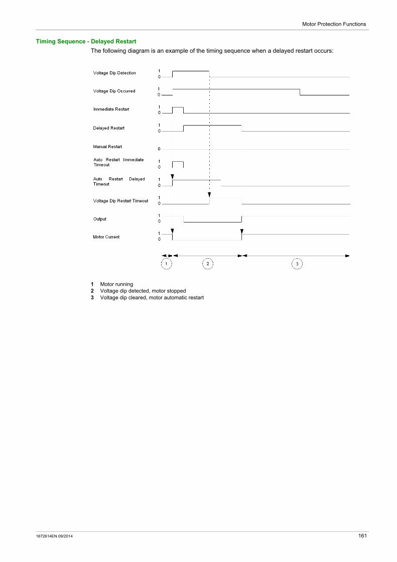
Motor Protection Functions
Timing Sequence - Delayed Restart
The following diagram is an example of the timing sequence when a delayed restart occurs:
1 Motor running2 Voltage dip detected, motor stopped3 Voltage dip cleared, motor automatic restart
1672614EN 09/2014 161

Motor Protection Functions
Timing Sequence - Manual Restart
The following diagram is an example of the timing sequence when a manual restart occurs:
1 Motor running2 Voltage dip detected, motor stopped3 Voltage dip cleared, motor automatic restart
162 1672614EN 09/2014
Motor Protection Functions
Power Motor Protection Functions
Section 3.5Power Motor Protection Functions
Overview
This section describes the power motor protection functions provided by the LTM R controller.
What Is in This Section?
This section contains the following topics:
Topic Page
Underpower 164
Overpower 166
Under Power Factor 168
Over Power Factor 170
1672614EN 09/2014 163

Motor Protection Functions
Underpower
Description
The underpower function signals:
a warning when the value of active power falls below a set threshold. a fault when the value of active power falls and remains below a separately set threshold for a set period
of time.
This function has a single fault time delay. Both the fault and warning thresholds are defined as a percentage of the Motor Nominal Power parameter setting (Pnom).
The underpower function is available only in run state, when the LTM R controller is connected to an expansion module.
Fault and warning monitoring can be separately enabled and disabled.
Functional Characteristics
The underpower function includes the following features:
2 thresholds: Underpower Warning Threshold Underpower Fault Threshold
1 fault time delay: Underpower Fault Timeout
2 function outputs: Underpower Warning Underpower Fault
1 counting statistic: Underpower Faults Count
Block Diagram
Vavg Average rms voltageIavg Average rms currentP PowerPs1 Warning thresholdPs2 Fault thresholdT Fault timeout
Parameter Settings
The underpower function has the following parameters:
Parameters Setting Range Factory Setting
Fault enable Enable/Disable Disable
Fault timeout 1...100 s in 1 s increments 60 s
Fault threshold 20...800 % of Motor nominal power in 1 % increments 20 %
Warning enable Enable/Disable Disable
Warning threshold 20...800 % of Motor nominal power in 1 % increments 30 %
164 1672614EN 09/2014

Motor Protection Functions
Technical Characteristics
The underpower function has the following characteristics:
Example
The following diagram describes the occurrence of an underpower fault.
Ps2 Underpower fault threshold
Characteristics Value
Hysteresis –5 % of Fault threshold or Warning threshold
Accuracy +/– 5%
1672614EN 09/2014 165
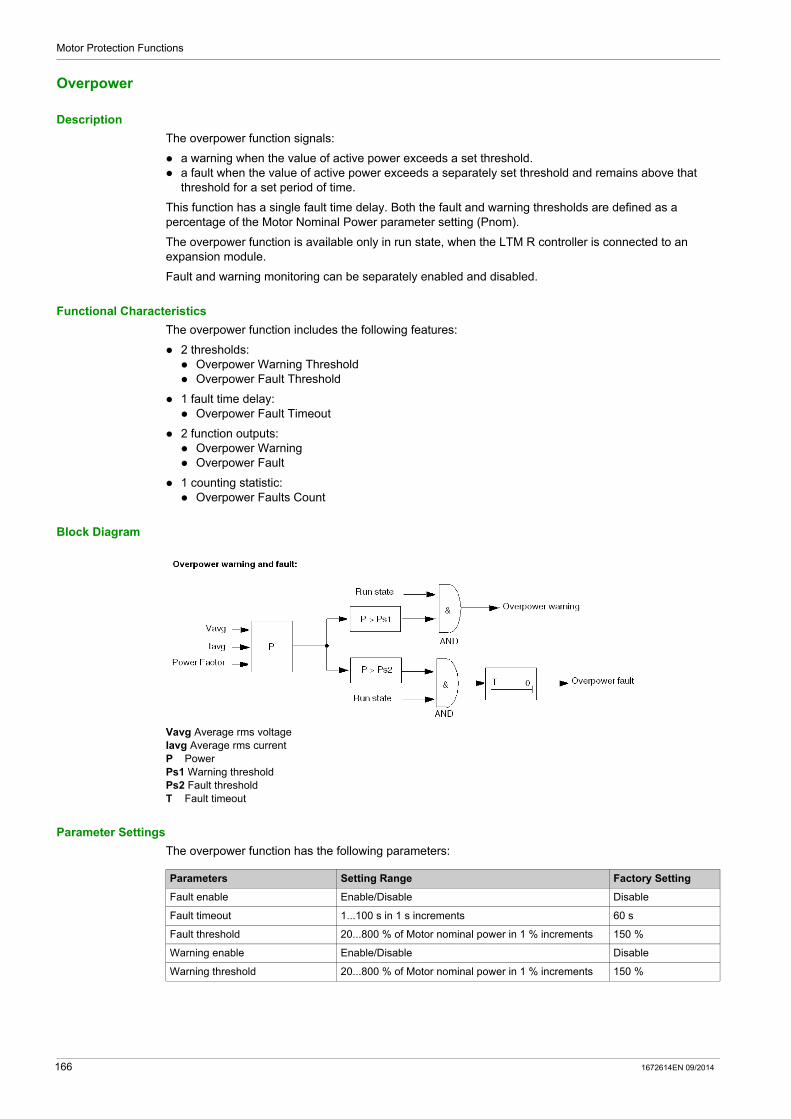
Motor Protection Functions
Overpower
Description
The overpower function signals:
a warning when the value of active power exceeds a set threshold. a fault when the value of active power exceeds a separately set threshold and remains above that
threshold for a set period of time.
This function has a single fault time delay. Both the fault and warning thresholds are defined as a percentage of the Motor Nominal Power parameter setting (Pnom).
The overpower function is available only in run state, when the LTM R controller is connected to an expansion module.
Fault and warning monitoring can be separately enabled and disabled.
Functional Characteristics
The overpower function includes the following features:
2 thresholds: Overpower Warning Threshold Overpower Fault Threshold
1 fault time delay: Overpower Fault Timeout
2 function outputs: Overpower Warning Overpower Fault
1 counting statistic: Overpower Faults Count
Block Diagram
Vavg Average rms voltageIavg Average rms currentP PowerPs1 Warning thresholdPs2 Fault thresholdT Fault timeout
Parameter Settings
The overpower function has the following parameters:
Parameters Setting Range Factory Setting
Fault enable Enable/Disable Disable
Fault timeout 1...100 s in 1 s increments 60 s
Fault threshold 20...800 % of Motor nominal power in 1 % increments 150 %
Warning enable Enable/Disable Disable
Warning threshold 20...800 % of Motor nominal power in 1 % increments 150 %
166 1672614EN 09/2014
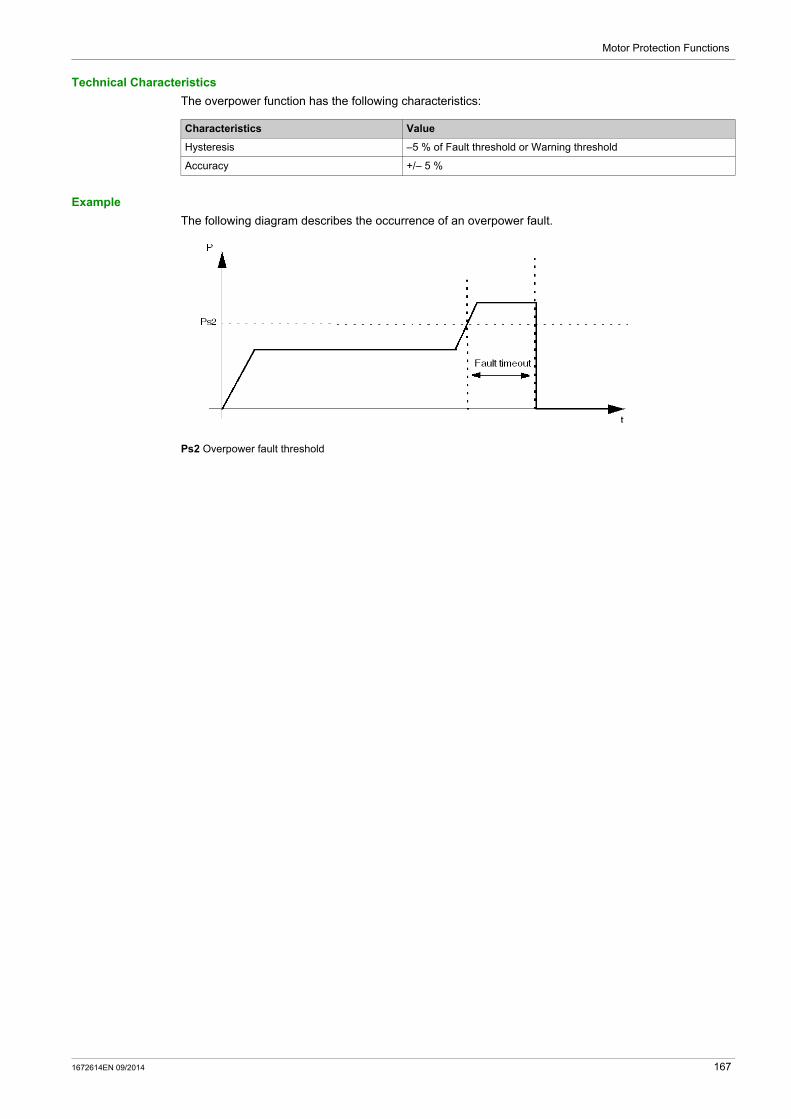
Motor Protection Functions
Technical Characteristics
The overpower function has the following characteristics:
Example
The following diagram describes the occurrence of an overpower fault.
Ps2 Overpower fault threshold
Characteristics Value
Hysteresis –5 % of Fault threshold or Warning threshold
Accuracy +/– 5 %
1672614EN 09/2014 167

Motor Protection Functions
Under Power Factor
Description
The under power factor protection function monitors the value of the power factor and signals:
a warning when the value of the power factor falls below a set threshold. a fault when the value of the power factor falls below a separately set threshold and remains below that
threshold for a set period of time.
This function has a single fault time delay.
The under power factor protection function is available only in run state, when the LTM R controller is connected to an expansion module.
Fault and warning monitoring can be separately enabled and disabled.
Functional Characteristics
The under power factor function includes the following features:
2 thresholds: Under Power Factor Warning Threshold Under Power Factor Fault Threshold
1 fault time delay: Under Power Factor Fault Timeout
2 function outputs: Under Power Factor Warning Under Power Factor Fault
1 counting statistic: Under Power Factor Faults Count
Block Diagram
cosϕs1 Under power factor warning thresholdcosϕs2 Under power factor fault thresholdT Under power factor fault timeout
Parameter Settings
The under power factor function has the following parameters:
Parameters Setting Range Factory Setting
Fault enable Enable/Disable Disable
Fault timeout 1...25 s in 0.1 s increments 10 s
Fault threshold 0...1 x Power factor in 0.01 increments 0.60
Warning enable Enable/Disable Disable
Warning threshold 0...1 x Power factor in 0.01 increments 0.60
168 1672614EN 09/2014
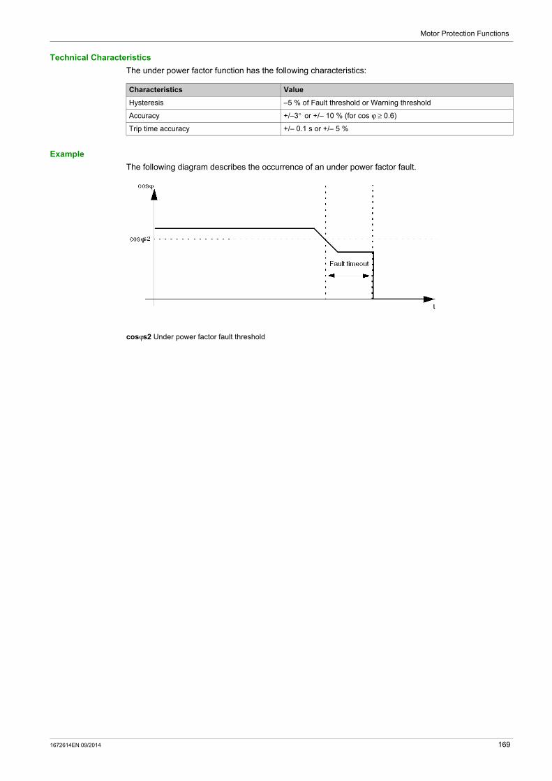
Motor Protection Functions
Technical Characteristics
The under power factor function has the following characteristics:
Example
The following diagram describes the occurrence of an under power factor fault.
cosϕs2 Under power factor fault threshold
Characteristics Value
Hysteresis –5 % of Fault threshold or Warning threshold
Accuracy +/–3° or +/– 10 % (for cos ϕ ≥ 0.6)
Trip time accuracy +/– 0.1 s or +/– 5 %
1672614EN 09/2014 169
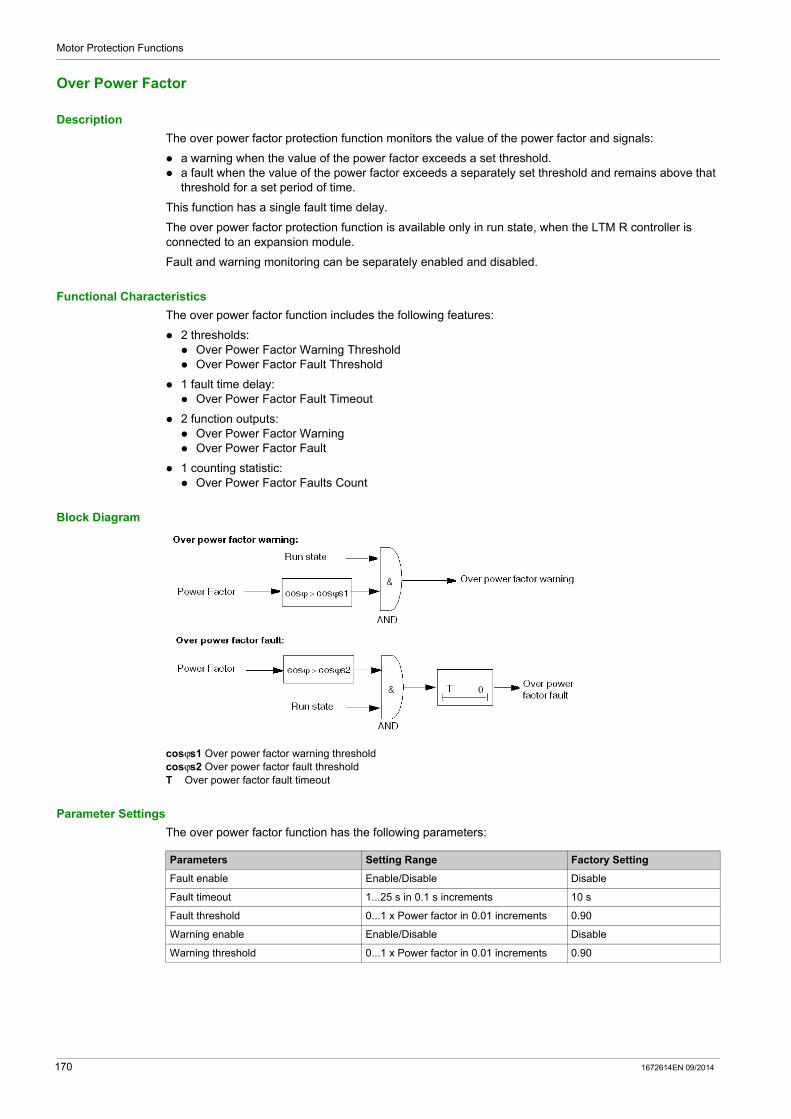
Motor Protection Functions
Over Power Factor
Description
The over power factor protection function monitors the value of the power factor and signals:
a warning when the value of the power factor exceeds a set threshold. a fault when the value of the power factor exceeds a separately set threshold and remains above that
threshold for a set period of time.
This function has a single fault time delay.
The over power factor protection function is available only in run state, when the LTM R controller is connected to an expansion module.
Fault and warning monitoring can be separately enabled and disabled.
Functional Characteristics
The over power factor function includes the following features:
2 thresholds: Over Power Factor Warning Threshold Over Power Factor Fault Threshold
1 fault time delay: Over Power Factor Fault Timeout
2 function outputs: Over Power Factor Warning Over Power Factor Fault
1 counting statistic: Over Power Factor Faults Count
Block Diagram
cosϕs1 Over power factor warning thresholdcosϕs2 Over power factor fault thresholdT Over power factor fault timeout
Parameter Settings
The over power factor function has the following parameters:
Parameters Setting Range Factory Setting
Fault enable Enable/Disable Disable
Fault timeout 1...25 s in 0.1 s increments 10 s
Fault threshold 0...1 x Power factor in 0.01 increments 0.90
Warning enable Enable/Disable Disable
Warning threshold 0...1 x Power factor in 0.01 increments 0.90
170 1672614EN 09/2014

Motor Protection Functions
Technical Characteristics
The over power factor function has the following characteristics:
Example
The following diagram describes the occurrence of an over power factor fault.
cosϕs2 Over power factor fault threshold
Characteristics Value
Hysteresis –5 % of Fault threshold or Warning threshold
Accuracy +/– 3° or +/– 10 % (for cos ϕ ≥ 0.6)
Trip time accuracy +/–0.1 s or +/– 5 %
1672614EN 09/2014 171

Motor Protection Functions
172 1672614EN 09/2014
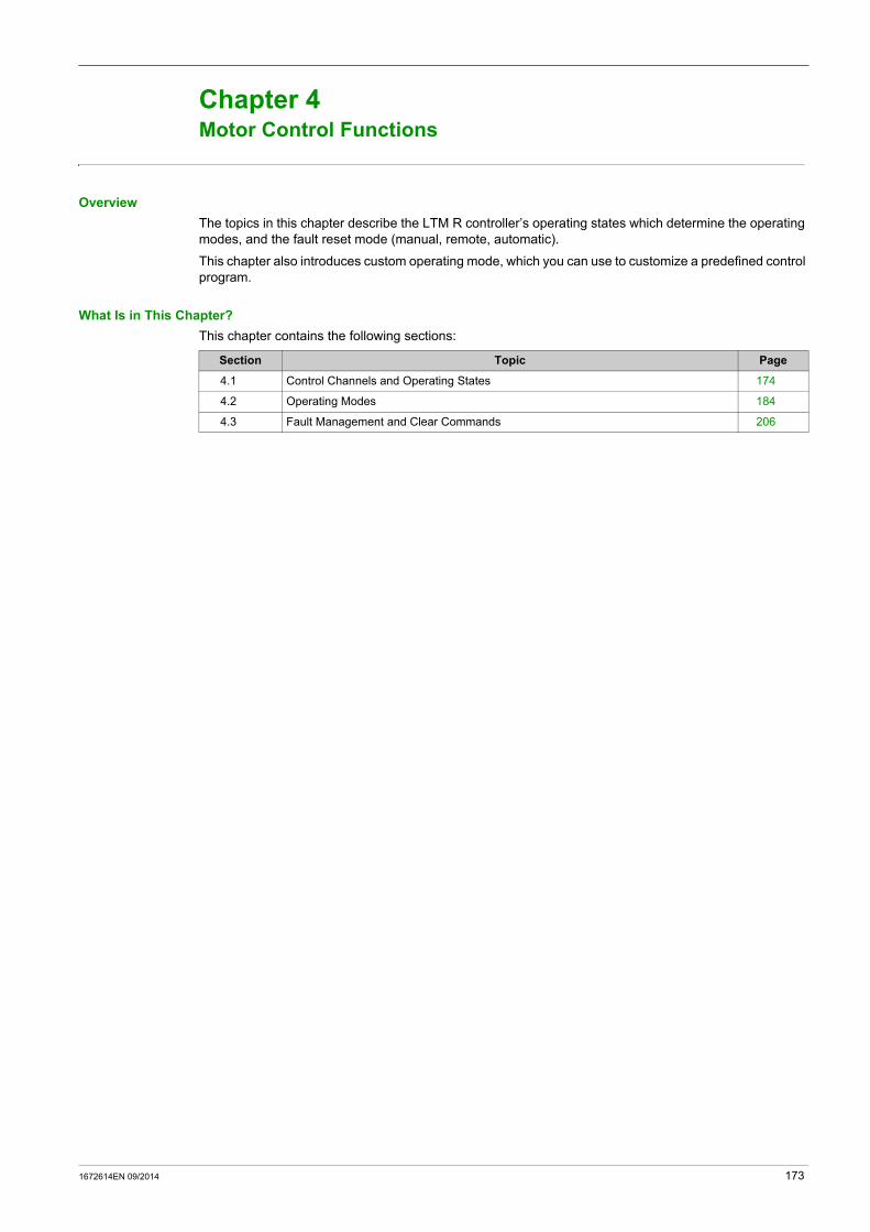
TeSys T DTM for FDT Container
Motor Control Functions
1672614EN 09/2014
Motor Control Functions
Chapter 4Motor Control Functions
Overview
The topics in this chapter describe the LTM R controller’s operating states which determine the operating modes, and the fault reset mode (manual, remote, automatic).
This chapter also introduces custom operating mode, which you can use to customize a predefined control program.
What Is in This Chapter?
This chapter contains the following sections:
Section Topic Page
4.1 Control Channels and Operating States 174
4.2 Operating Modes 184
4.3 Fault Management and Clear Commands 206
1672614EN 09/2014 173

Motor Control Functions
Control Channels and Operating States
Section 4.1Control Channels and Operating States
Overview
This section describes:
how to configure control of the LTM R controller outputs, and the LTM R controller’s operating states, including: how the LTM R controller transitions between operating states during startup, and the motor protection functions provided by the LTM R controller in each operating state
What Is in This Section?
This section contains the following topics:
WARNINGUNINTENDED EQUIPMENT OPERATION
The application of this product requires expertise in the design and programming of control systems. Only persons with such expertise should be allowed to program, install, alter and apply this product. Follow all local and national safety codes and standards.
Failure to follow these instructions can result in death, serious injury, or equipment damage.
Topic Page
Control Channels 175
Operating States 178
Start Cycle 181
174 1672614EN 09/2014
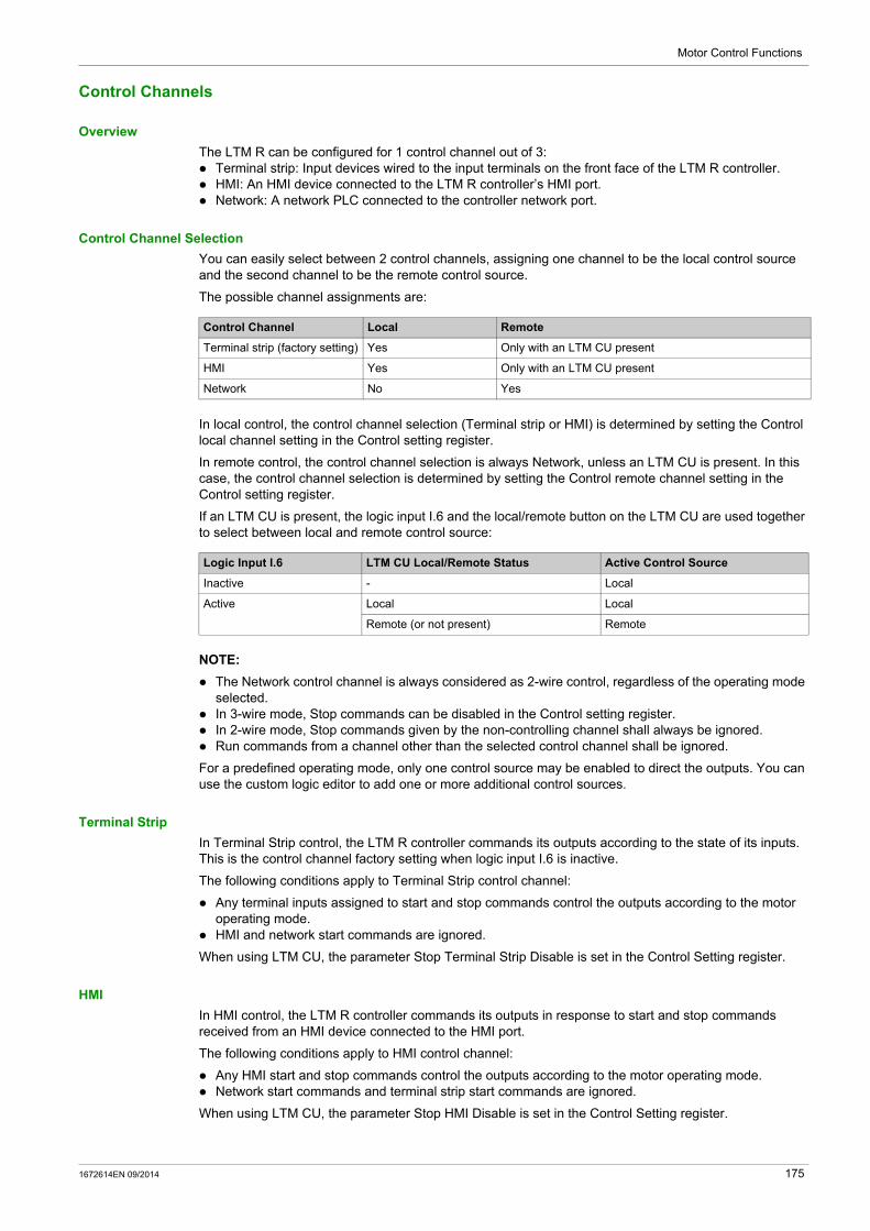
Motor Control Functions
Control Channels
Overview
The LTM R can be configured for 1 control channel out of 3: Terminal strip: Input devices wired to the input terminals on the front face of the LTM R controller. HMI: An HMI device connected to the LTM R controller’s HMI port. Network: A network PLC connected to the controller network port.
Control Channel Selection
You can easily select between 2 control channels, assigning one channel to be the local control source and the second channel to be the remote control source.
The possible channel assignments are:
In local control, the control channel selection (Terminal strip or HMI) is determined by setting the Control local channel setting in the Control setting register.
In remote control, the control channel selection is always Network, unless an LTM CU is present. In this case, the control channel selection is determined by setting the Control remote channel setting in the Control setting register.
If an LTM CU is present, the logic input I.6 and the local/remote button on the LTM CU are used together to select between local and remote control source:
NOTE:
The Network control channel is always considered as 2-wire control, regardless of the operating mode selected.
In 3-wire mode, Stop commands can be disabled in the Control setting register. In 2-wire mode, Stop commands given by the non-controlling channel shall always be ignored. Run commands from a channel other than the selected control channel shall be ignored.
For a predefined operating mode, only one control source may be enabled to direct the outputs. You can use the custom logic editor to add one or more additional control sources.
Terminal Strip
In Terminal Strip control, the LTM R controller commands its outputs according to the state of its inputs. This is the control channel factory setting when logic input I.6 is inactive.
The following conditions apply to Terminal Strip control channel:
Any terminal inputs assigned to start and stop commands control the outputs according to the motor operating mode.
HMI and network start commands are ignored.
When using LTM CU, the parameter Stop Terminal Strip Disable is set in the Control Setting register.
HMI
In HMI control, the LTM R controller commands its outputs in response to start and stop commands received from an HMI device connected to the HMI port.
The following conditions apply to HMI control channel:
Any HMI start and stop commands control the outputs according to the motor operating mode. Network start commands and terminal strip start commands are ignored.
When using LTM CU, the parameter Stop HMI Disable is set in the Control Setting register.
Control Channel Local Remote
Terminal strip (factory setting) Yes Only with an LTM CU present
HMI Yes Only with an LTM CU present
Network No Yes
Logic Input I.6 LTM CU Local/Remote Status Active Control Source
Inactive - Local
Active Local Local
Remote (or not present) Remote
1672614EN 09/2014 175

Motor Control Functions
Network
In Network control, a remote PLC sends commands to the LTM R controller through the network communication port.
The following conditions apply to Network control channel:
Any network start and stop commands control the outputs according to the motor operating mode. The HMI unit can read (but not write) the LTM R controller parameters.
Control Transfer Mode
Select the Control Transfer Mode parameter to enable bumpless transfer when changing the control channel; clear this parameter to enable bump transfer. The configuration setting for this parameter determines the behavior of logic outputs O.1 and O.2, as follows:
When you start the motor in Remote control mode with the PLC, the LTM R controller changes to Local control mode (I.6=1 to I.6=0) and the status of the motor changes depending on the control transfer mode, as follows:
When the LTM R controller changes from Local to Remote control mode (I.6=0 to I.6=1), the status of the motor in Local control mode, whether running or stopped, remains unchanged. The control transfer mode selected does not affect the status of the motor as the LTM R controller only takes account of the last control command (logic outputs O.1 or O.2) sent by the PLC.
Control Transfer Mode Setting LTM R Controller Behavior When Changing Control Channel
Bump Logic outputs O.1 and O.2 open (if closed) or remain open (if already open) until the next valid signal occurs. The motor stops.Note: In overload predefined operating mode, logic outputs O.1 and O.2 are user-defined and therefore may not be affected by a Bump transfer.
Bumpless Logic outputs O.1 and O.2 are not affected and remain in their original position until the next valid signal occurs. The motor does not stop.
If the LTM R controller configuration is... Then the control mode changes from Remote to Local and the motor…
3-Wire Bumpless keeps running
2-Wire Bumpless keeps running if the logic inputs I.1 or I.2 are activated
3-Wire Bump stops
2-Wire Bump
CAUTIONFAILURE TO STOP AND RISK OF UNINTENDED OPERATION
LTM R controller operation cannot be stopped from the terminals when control channel is changed to Terminal Strip control channel if the LTM R controller is:
operating in Overload operating mode- and -
configured in Bumpless- and -
operated over a network using Network control channel- and -
operating in Run state- and -
configured for 3-wire (impulse) control.
See instructions below.
Failure to follow these instructions can result in injury or equipment damage.
176 1672614EN 09/2014

Motor Control Functions
Whenever control channel is changed to Terminal Strip control channel, operation of the LTM R controller cannot be stopped from the terminals because no terminal input is assigned to a STOP command.
If this behavior is not intended, the control channel must be changed to either Network control channel or HMI control channel to command a STOP. To implement this change, take one of the following precautionary steps: the commissioner should configure the LTM R controller for either bump transfer of control channel or
2-wire control. the installer should provide the LTM R controller with a means of interrupting current to the contactor
coil - for example, a push button station wired in series with the LTM R controller outputs. the controls engineer should assign a terminal input to disable the Run command using Custom
Configuration Mode assignments.
Fallback Transitions
The LTM R controller enters a fallback state when communication with the control source is lost, and exits the fallback state when communication is restored. The transition into and out of the fallback state is as follows:
For information on how to configure communications fallback parameters, refer to the topic Communication Loss (see page 74).
When using LTM CU, the parameters Control Transfer Mode and Control Direct Transition parameters are set in the Control Setting register.
Transition Control Source Transfer
Entering the fallback state Bumpless, when the Control Direct Transition bit is on
Exiting the fallback state Determined by the settings for Control Transfer Mode (bump or bumpless) and Control Direct Transition (on or off)
1672614EN 09/2014 177
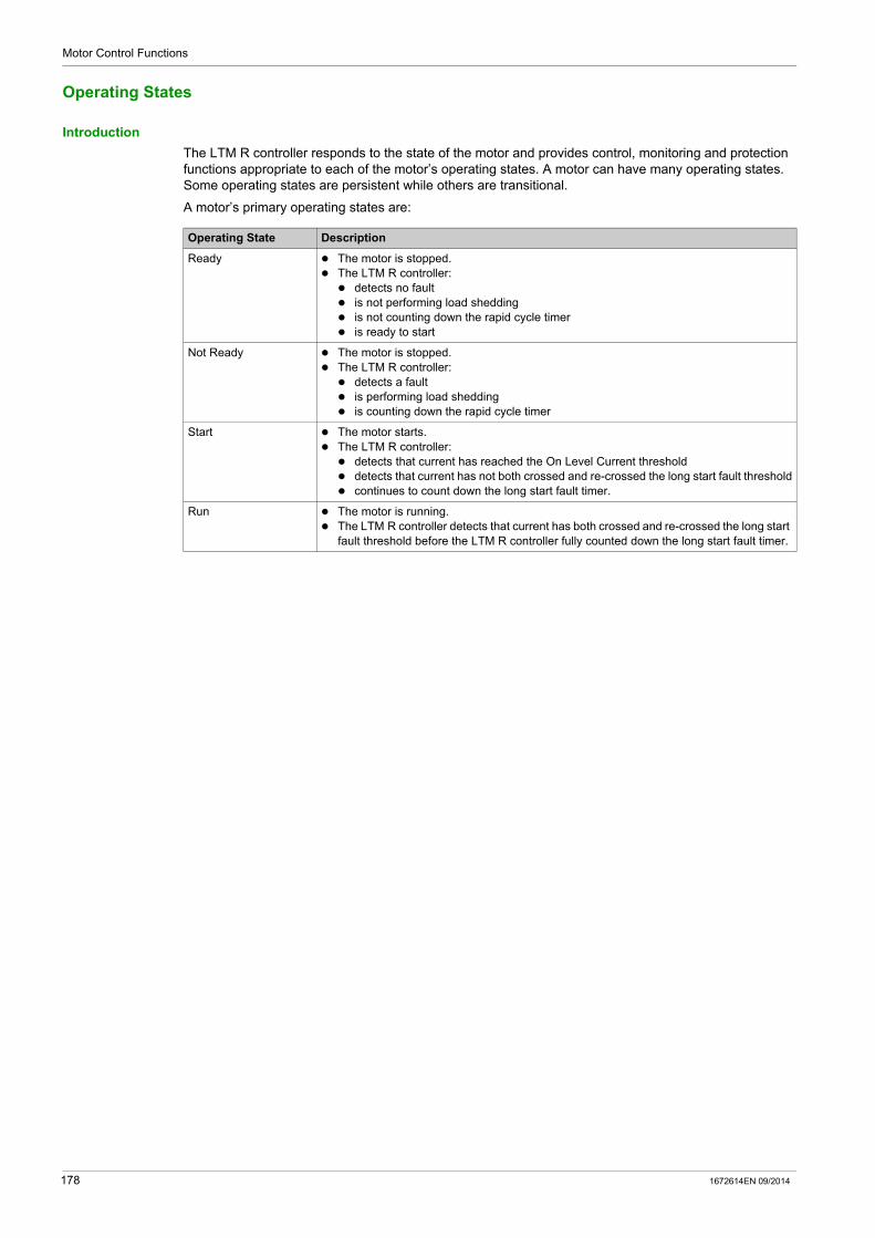
Motor Control Functions
Operating States
Introduction
The LTM R controller responds to the state of the motor and provides control, monitoring and protection functions appropriate to each of the motor’s operating states. A motor can have many operating states. Some operating states are persistent while others are transitional.
A motor’s primary operating states are:
Operating State Description
Ready The motor is stopped. The LTM R controller: detects no fault is not performing load shedding is not counting down the rapid cycle timer is ready to start
Not Ready The motor is stopped. The LTM R controller: detects a fault is performing load shedding is counting down the rapid cycle timer
Start The motor starts. The LTM R controller: detects that current has reached the On Level Current threshold detects that current has not both crossed and re-crossed the long start fault threshold continues to count down the long start fault timer.
Run The motor is running. The LTM R controller detects that current has both crossed and re-crossed the long start
fault threshold before the LTM R controller fully counted down the long start fault timer.
178 1672614EN 09/2014

Motor Control Functions
Operating State Chart
The operating states of the LTM R controller firmware, as the motor progresses from Off to Run state, are described below. The LTM R controller verifies current in each operating state. The LTM R controller can transition to an internal fault condition from any operating state.
Protection Monitoring by Operating States
The motor operating states, and the fault and warning protections provided by the LTM R controller while the motor is in each operating state (denoted with an X), are described below. It can transition to an internal fault condition from any operating state.
Protection Category Monitored Fault/Warning Operating States
Sys Config Ready Not Ready Start Run
Diagnostic Run Command Check – X – – –
Stop Command Check – – X X X
Run Check Back – – – X X
Stop Check Back – – – X X
Wiring / configuration errors PTC connection – X X X X
CT Reversal – – – X –
Voltage Phase Loss – X X – –
Phase Configuration – – – X –
Internal faults Minor X X X X X
Major X X X X X
X Monitored– Not monitored
1672614EN 09/2014 179

Motor Control Functions
Motor temp sensor PTC Binary – X X X X
PT100 – X X X X
PTC Analog – X X X X
NTC Analog – X X X X
Thermal overload Definite – – – – X
Inverse Thermal – X X X X
Current Long Start – – – X –
Jam – – – – X
Current Phase Imbalance – – – X X
Current Phase Loss – – – X X
Overcurrent – – – – X
Undercurrent – – – – X
Ground Fault (Internal) – – – X X
Ground Fault (External) – – – X X
Voltage Overvoltage Level – X X – X
Undervoltage Level – X X – X
Voltage Phase Imbalance – – – X X
Power / Power Factor Over Power Factor Level – – – – X
Under Power Factor Level – – – – X
Overpower Level – – – – X
Underpower Level – – – – X
Protection Category Monitored Fault/Warning Operating States
Sys Config Ready Not Ready Start Run
X Monitored– Not monitored
180 1672614EN 09/2014

Motor Control Functions
Start Cycle
Description
The start cycle is the time period allowed for the motor to reach its normal FLC level. The LTM R controller measures the start cycle in seconds, beginning when it detects On Level Current, defined as maximum phase current equal to 20 % of FLC.
During the start cycle, the LTM R controller compares:
detected current against the configurable Long Start Fault Threshold parameter, and elapsed start cycle time against the configurable Long Start Fault Timeout parameter.
There are 3 start cycle scenarios, each based on the number of times (0,1 or 2) maximum phase current crosses the Long Start Fault Threshold. A description of each scenario is described below.
For information on the statistics the LTM R controller retains describing motor starts, see Motor Starts Counters, page 91. For information about the long start protection function, see Long Start, page 132.
Start Cycle Operating States
During the start cycle, the LTM R controller transitions through the motor’s operating states as follows:
Step Event Operating State
1 LTM R controller receives a start command input signal. Ready
2 The LTM R controller confirms that all startup preconditions exist (e.g. no faults, load shedding, or rapid cycle timer).
Ready
3 The LTM R controller closes the appropriate output contacts designated as terminals 13-14 or 23-24, thereby closing the control circuit of the motor starting contactors.
Ready
4 The LTM R controller detects that maximum phase current exceeds the On Level Current threshold.
Start
5 The LTM R controller detects that current rises above and then falls below the Long Start Fault Threshold before the Long Start Fault Timeout timer expires.
Run
1672614EN 09/2014 181

Motor Control Functions
2 Threshold Crosses
In this start cycle scenario, the start cycle executes successfully:
Current rises above, then drops below, the fault threshold. The LTM R controller reports the actual start cycle time, i.e. the time elapsed from detection of On Level
Current until the maximum phase current drops below the fault threshold.
Start cycle with 2 threshold crosses, single step:
Is Long start fault threshold
Start cycle with 2 threshold crosses, 2 step:
182 1672614EN 09/2014

Motor Control Functions
1 Threshold Cross
In this start cycle scenario, the start cycle fails:
Current rises above, but fails to drop below, the Long Start Fault Threshold. If Long Start protection is enabled, the LTM R controller signals a fault when the Long Start Fault
Timeout is reached If Long Start protection is disabled, the LTM R controller does not signal a fault and the run cycle begins
after the Long Start Fault Timeout has expired. Other motor protection functions begin their respective duration times after the Long Start Fault
Timeout. The LTM R controller reports start cycle time as 9999, indicating that current exceeded and remained
above the fault threshold. The LTM R controller reports the maximum current detected during the start cycle.
Start cycle with 1 threshold cross:
0 Threshold Cross
In this start cycle scenario, the start cycle fails:
Current never rises above the fault threshold. If Long Start protection is enabled, the LTM R controller signals a fault when the Long Start Fault
Timeout is reached If Long Start protection is disabled, the LTM R controller does not signal a fault and the run cycle begins
after the Long Start Fault Timeout has expired. Other motor protection functions begin their respective duration times after the Long Start Fault
Timeout. The LTM R controller reports both the start cycle time and the maximum current detected during start
cycle as 0000, indicating current never reached the fault threshold.
Start cycle with 0 threshold cross:
Is Long start fault threshold
1672614EN 09/2014 183
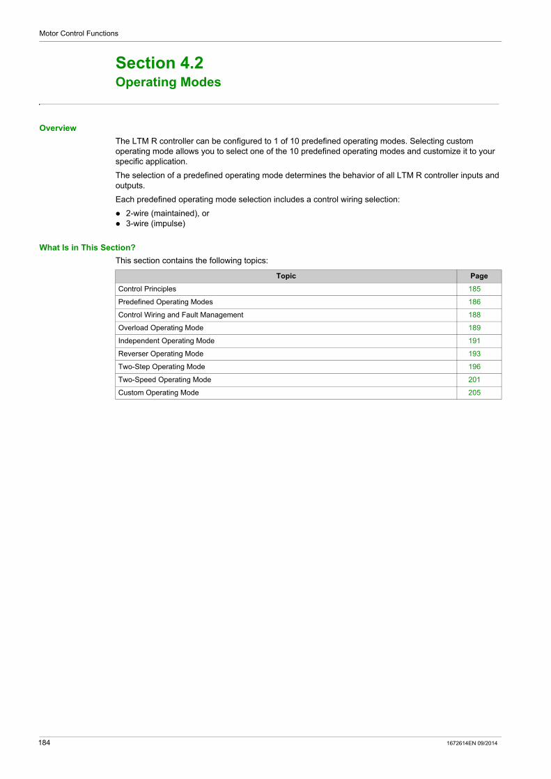
Motor Control Functions
Operating Modes
Section 4.2Operating Modes
Overview
The LTM R controller can be configured to 1 of 10 predefined operating modes. Selecting custom operating mode allows you to select one of the 10 predefined operating modes and customize it to your specific application.
The selection of a predefined operating mode determines the behavior of all LTM R controller inputs and outputs.
Each predefined operating mode selection includes a control wiring selection:
2-wire (maintained), or 3-wire (impulse)
What Is in This Section?
This section contains the following topics:
Topic Page
Control Principles 185
Predefined Operating Modes 186
Control Wiring and Fault Management 188
Overload Operating Mode 189
Independent Operating Mode 191
Reverser Operating Mode 193
Two-Step Operating Mode 196
Two-Speed Operating Mode 201
Custom Operating Mode 205
184 1672614EN 09/2014
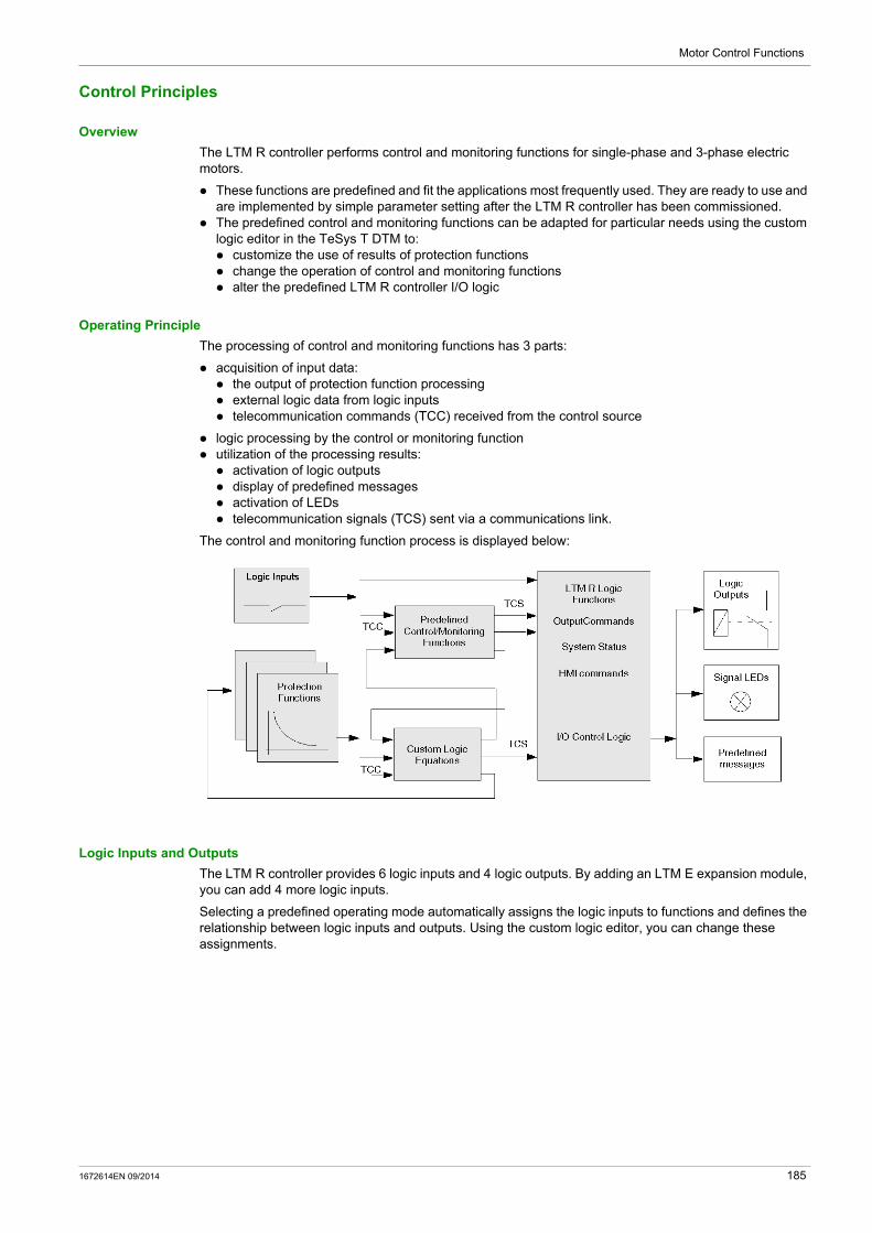
Motor Control Functions
Control Principles
Overview
The LTM R controller performs control and monitoring functions for single-phase and 3-phase electric motors.
These functions are predefined and fit the applications most frequently used. They are ready to use and are implemented by simple parameter setting after the LTM R controller has been commissioned.
The predefined control and monitoring functions can be adapted for particular needs using the custom logic editor in the TeSys T DTM to: customize the use of results of protection functions change the operation of control and monitoring functions alter the predefined LTM R controller I/O logic
Operating Principle
The processing of control and monitoring functions has 3 parts:
acquisition of input data: the output of protection function processing external logic data from logic inputs telecommunication commands (TCC) received from the control source
logic processing by the control or monitoring function utilization of the processing results: activation of logic outputs display of predefined messages activation of LEDs telecommunication signals (TCS) sent via a communications link.
The control and monitoring function process is displayed below:
Logic Inputs and Outputs
The LTM R controller provides 6 logic inputs and 4 logic outputs. By adding an LTM E expansion module, you can add 4 more logic inputs.
Selecting a predefined operating mode automatically assigns the logic inputs to functions and defines the relationship between logic inputs and outputs. Using the custom logic editor, you can change these assignments.
1672614EN 09/2014 185

Motor Control Functions
Predefined Operating Modes
Overview
The LTM R controller can be configured in 1 out of 10 predefined operating modes. Each operating mode is designed to meet the requirements of a common application configuration.
When you select an operating mode, you specify both the:
operating mode type, which determines the relationship between logic inputs and logic outputs, and control circuit type, which determines logic input behavior, based on the control wiring design
Operating Mode Types
There are 10 types of operating modes:
Logic Input Behavior
When you select an operating mode, you also specify that logic inputs are wired for either 2-wire (maintained) or 3-wire (impulse) control. Your selection determines the valid start and stop commands from the various control sources, and sets the behavior of the input command following the return of power after an outage:
Control logic assignments for logic inputs I.1, I.2, I.3 and I.4 are described in each of the predefined motor operating modes.
NOTE: In Network control channel, network commands behave as 2-wire control commands, regardless of the control circuit type of the selected operating mode. For information on Control Channels, see Control Channels, page 175.
Operating Mode Type Best used for:
Overload (see page 189) All motor starter applications in which the user defines assignment of: logic inputs I.1, I.2, I.3 and I.4 logic outputs O.1 and O.2 Aux1, Aux2 and Stop commands from the HMI keypad.
The I/O can be defined using a control program managed by the master network controller in remote control, by an HMI tool, or by using custom logic.
Independent (see page 191)
Direct-on-line (across-the-line) full-voltage non-reversing motor starting applications
Reverser (see page 193) Direct-on-line (across-the-line) full-voltage reversing motor starting applications
Two-Step (see page 196) Reduced voltage starting motor applications, including: Wye-Delta Open Transition Primary Resistor Open Transition Autotransformer
Two-Speed (see page 201) Two-speed motor applications for motor types, including: Dahlander (consequent pole) Pole Changer
Control Circuit Type Behavior of Logic Inputs I.1 and I.2
2-wire (maintained) The LTM R controller, after detecting the rising edge on the input assigned to start the motor, issues a run command. The run command remains active only while the input is active. The signal is not latched.
3-wire (impulse) The LTM R controller: After detecting the rising edge on the input assigned to start the motor, latch the run
command, and After a stop command, disables the run command to disable the output relay wired
in series with the coil of the contactor that turns the motor on or off Following a stop, must detect a rising edge on the input to latch the run command.
186 1672614EN 09/2014

Motor Control Functions
In each predefined operating mode, logic inputs I.3, I.4, I.5 and I.6 behave as follows:
Logic Output Behavior
The behavior of logic outputs O.1 and O.2 is determined by the selected operating mode. See the topics that follow for a description of the 10 predefined operating mode types and the behavior of logic outputs O.1 and O.2.
When the LTM R controller has lost communication with either the network or the HMI, the LTM R controller enters a fallback condition. When it receives a stop command in a fallback condition, logic outputs O.1 and O.2 behave as follows:
For more information about configuring fallback parameters, refer to the Fallback Condition (see page 74) portion of the topic describing Communication Loss.
In all operating mode types, the following logic outputs behave as described below:
Logic Input Behavior
I.3 When it is configured to be used as the external system ready input (Logic Input 3 External Ready Enable = 1), this input provides a feedback on the system state (Ready or not): If I.3 = 0, the external system is not ready. System Ready bit (455.0) is set to 0. If I.3 = 1, the external system is ready. System Ready bit (455.0) can be set to 1
depending on other conditions on the system.
When it is not configured to be used as the external system ready input (Logic Input 3 External Ready Enable = 0), this input is user defined and only sets a bit in a register.
I.4 In 3-wire (impulse) control: a Stop command. Note that this stop command can be disabled in terminal strip control by setting the parameter Stop terminal strip disable in the Control setting register.
In 2-wire (maintained) control: a user-defined input that can be configured to send information to a PLC address over the network.
Note: In Overload operating mode, logic input I.4 is not used and can be user-defined.
I.5 A Fault Reset command is recognized when this input receives the rising edge of a signal.Note: this input must first become inactive, and then receive the rising edge of a subsequent signal, for another reset to occur.
I.6 Local/Remote control of the LTM R controller’s outputs: Active: Remote control (can be associated to any Control channel). Inactive: Local control through either the terminal strip or the HMI port, as determined by
the Control Local Channel Setting parameter.
WARNINGLOSS OF MOTOR PROTECTION IN HMI CONTROL
If the terminal strip Stop is disabled, the fault output (terminal NC 95-96) must be wired in series with the contactor coil.
Failure to follow these instructions can result in death, serious injury, or equipment damage.
Control Circuit Type Response of Logic Outputs O.1 and O.2 to a Stop Command
2-wire (maintained) A stop command overrides the fallback condition and turns off logic outputs O.1 and O.2 while the stop command is active. After the stop command is no longer active, logic outputs O.1 and O.2 return to their programmed fallback state.
3-wire (impulse) A stop command overrides the fallback condition and turns off logic outputs O.1 and O.2. The outputs remain off after the stop command is removed and do not return to their programmed fallback state.
Logic Output Behavior
O.3 Activated by any enabled protection warning: Terminals NO 33-34
O.4 Activated by any enabled protection fault: Terminals NC 95-96 Terminals NO 97-98
Note: When control voltage is too low or off: NC 95-96 open NO 97-98 close
1672614EN 09/2014 187

Motor Control Functions
Control Wiring and Fault Management
Overview
When Overload predefined operating mode is selected, the LTM R controller does not manage logic output O.1, O.2, and O.3.
For all other predefined operating modes (Independent, Reverser, 2-Step, and 2-Speed) the predefined control logic in the LTM R controller is designed to meet the objectives of many common motor starting applications. This includes managing motor behavior in response to:
start and stop actions, and fault and reset actions
Because the LTM R controller can be used in special applications, such as fire pumps that require the motor to run despite a known external fault condition, the predefined control logic is designed so that the control circuit, and not the predefined control logic, determines how the LTM R controller interrupts current flow to the contactor coil.
Control Logic Action on Starts and Stops
Predefined control logic acts upon start and stop commands as follows:
For all 3-wire (impulse) control wiring diagrams, when input 4 is configured as a stop command, the LTM R controller must detect input current at logic input I.4 in order to act on a start command.
If logic input I.4 is active and a user start action initiates current at logic inputs I.1 or I.2, the LTM R controller detects the rising edge of the current and sets an internal (firmware) latch command that directs the appropriate relay output to close and remain closed until the latch command is disabled.
A stop action that interrupts current at logic input I.4, causes the LTM R controller to disable the latch command. Disabling the firmware latch causes the output to open–and remain open–until the next valid start condition.
For all 2-wire (maintained) control wiring diagrams, the LTM R controller detects the presence of current at logic inputs I.1 or I.2 as start commands, and the absence of current disables the start command.
Control Logic Action on Faults and Resets
Predefined control logic manages faults and reset commands as follows:
Logic output O.4 opens in response to a fault condition. Logic output O.4 closes in response to a reset command.
Control Logic and Control Wiring Together Managing Faults
The control circuits, shown in the wiring diagrams in this chapter and in the Appendix, indicate how the LTM R controller’s control logic and the control circuit combine to stop a motor in response to a fault:
For 3-wire (impulse) control circuits, the control strategy links the state of logic output O.4 to the state of the current at logic input I.4: Control logic opens logic output O.4 in response to a fault. Logic output O.4 opening interrupts current at logic input I.4, disabling the control logic latch
command on logic output O.1. Logic output O.1 opens, due to control logic described above, and stops the flow of current to the
contactor coil.
In order to restart the motor, the fault must be reset and a new start command must be issued. For 2-wire (maintained) control circuits, the control strategy links the state of logic output O.4 directly
with the logic inputs I.1 or I.2. Control logic opens logic output O.4 in response to a fault. Logic output O.4 opening interrupts current to the logic inputs I.1 or I.2 Control logic disables the start commands opening logic outputs O.1 or O.2.
In order to restart the motor, the fault must be reset and the state of Start/Stop operators determines the state of logic inputs I.1 or I.2.
The control circuits needed to run a motor, during a motor protection fault, are not shown in the wiring diagrams that follow. However, the control strategy is to not link the state of logic output O.4 to the state of the input commands. In this way, fault conditions may be annunciated, while control logic continues to manage Start and Stop commands.
188 1672614EN 09/2014

Motor Control Functions
Overload Operating Mode
Description
Use Overload operating mode when motor load monitoring is required and motor load control (start/stop) is performed by a mechanism other than the LTM R controller.
Functional Characteristics
The Overload operating mode includes the following features:
The LTM R controller overload operating mode does not manage logic outputs O.1, O.2, and O.3. The logic output O.1 and O.2 commands are accessible in Network control channel.
Logic output O.4 opens in response to a diagnostic error.NOTE: In Overload operating mode, diagnostic error is disabled by default. If needed, it can be enabled by the user.
The LTM R controller sets a bit in a status word when it detects an active signal: on logic inputs I.1, I.2, I.3, or I.4, or from the Aux 1, Aux 2, or Stop buttons on the HMI keypad.
NOTE: When a bit is set in the input status word, it can be read by a PLC which can write a bit to the LTM R controller’s command word. When the LTM R controller detects a bit in its command word, it can turn on the respective output (or outputs).
Overload Application Diagram
The following wiring diagram represents a simplified example of the LTM R controller in a 3-wire (impulse) terminal strip control overload application.
For additional examples of overload operating mode IEC diagrams, refer to relevant diagrams .
For examples of overload operating mode NEMA diagrams, refer to relevant diagrams .
1672614EN 09/2014 189

Motor Control Functions
I/O Assignment
Overload operating mode provides the following logic inputs:
Overload operating mode provides the following logic outputs:
Overload operating mode uses the following HMI keys:
Parameters
Overload operating mode requires no associated parameter settings.
Logic Inputs Assignment
I.1 Free
I.2 Free
I.3 Free
I.4 Free
I.5 Reset
I.6 Local (0) or Remote (1)
Logic Outputs Assignment
O.1 (13 and 14) Responds to network control commands
O.2 (23 and 24) Responds to network control commands
O.3 (33 and 34) Warning signal
O.4 (95, 96, 97, and 98) Fault signal
HMI Keys Assignment
Aux 1 Free
Aux 2 Free
Stop Free
190 1672614EN 09/2014
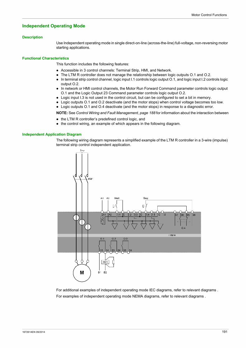
Motor Control Functions
Independent Operating Mode
Description
Use Independent operating mode in single direct-on-line (across-the-line) full-voltage, non-reversing motor starting applications.
Functional Characteristics
This function includes the following features:
Accessible in 3 control channels: Terminal Strip, HMI, and Network. The LTM R controller does not manage the relationship between logic outputs O.1 and O.2. In terminal strip control channel, logic input I.1 controls logic output O.1, and logic input I.2 controls logic
output O.2. In network or HMI control channels, the Motor Run Forward Command parameter controls logic output
O.1 and the Logic Output 23 Command parameter controls logic output O.2. Logic input I.3 is not used in the control circuit, but can be configured to set a bit in memory. Logic outputs O.1 and O.2 deactivate (and the motor stops) when control voltage becomes too low. Logic outputs O.1 and O.4 deactivate (and the motor stops) in response to a diagnostic error.
NOTE: See Control Wiring and Fault Management, page 188 for information about the interaction between
the LTM R controller’s predefined control logic, and the control wiring, an example of which appears in the following diagram.
Independent Application Diagram
The following wiring diagram represents a simplified example of the LTM R controller in a 3-wire (impulse) terminal strip control independent application.
For additional examples of independent operating mode IEC diagrams, refer to relevant diagrams .
For examples of independent operating mode NEMA diagrams, refer to relevant diagrams .
1672614EN 09/2014 191

Motor Control Functions
I/O Assignment
Independent operating mode provides the following logic inputs:
Independent operating mode provides the following logic outputs:
Independent operating mode uses the following HMI keys:
Timing Sequence
The following diagram is an example of the timing sequence for the Independent operating mode that shows the inputs and outputs for a 3-wire (impulse) configuration:
1 Normal operation2 Start command ignored: stop command active
Parameters
Independent operating mode requires no associated parameters.
Logic Inputs 2-Wire (Maintained) Assignment 3-Wire (Impulse) Assignment
I.1 Start/Stop motor Start motor
I.2 Open/Close O.2 Close O.2
I.3 Free Free
I.4 Free Stop motor and open O.1 and O.2
I.5 Reset Reset
I.6 Local (0) or Remote (1) Local (0) or Remote (1)
Logic Outputs Assignment
O.1 (13 and 14) KM1 contactor control
O.2 (23 and 24) Controlled by I.2
O.3 (33 and 34) Warning signal
O.4 (95, 96, 97, and 98) Fault signal
HMI Keys 2-Wire (Maintained) Assignment 3-Wire (Impulse) Assignment
Aux 1 Control motor Start motor
Aux 2 Control O.2 Close O.2
Stop Stop motor and open O.2 while pressed Stop motor and open O.2
192 1672614EN 09/2014
Motor Control Functions
Reverser Operating Mode
Description
Use Reverser operating mode in direct-on-line (across-the-line) full-voltage, reversing motor starting applications.
Functional Characteristics
This function includes the following features:
Accessible in 3 control channels: Terminal Strip, HMI, and Network. Firmware interlocking prevents simultaneous activation of the O.1 (forward) and O.2 (reverse) logic
outputs: in case of simultaneous forward and reverse commands, only the logic output O.1 (forward) is activated.
The LTM R controller can change direction from forward to reverse and reverse to forward in 1 of 2 modes: Standard Transition mode: The Control Direct Transition bit is Off. This mode requires a Stop
command followed by count-down of the adjustable Motor Transition Timeout (anti-backspin) timer. Direct Transition mode: The Control Direct Transition bit is On. This mode automatically transitions
after the count-down of the adjustable Motor Transition Timeout (anti-backspin) timer.
In terminal strip control channel, logic input I.1 controls logic output O.1, and logic input I.2 controls logic output O.2.
In Network or HMI control channels, the Motor Run Forward Command parameter controls logic output O.1 and the Motor Run Reverse Command controls logic output O.2.
Logic input I.3 is not used in the control circuit, but can be configured to set a bit in memory. Logic outputs O.1 and O.2 deactivate (and the motor stops) when control voltage becomes too low. Logic outputs O.1, O.2 and O.4 deactivate (and the motor stops) in response to a diagnostic error.
NOTE: See Control Wiring and Fault Management, page 188 for information about the interaction between
the LTM R controller’s predefined control logic, and the control wiring, an example of which appears in the following diagram.
1672614EN 09/2014 193
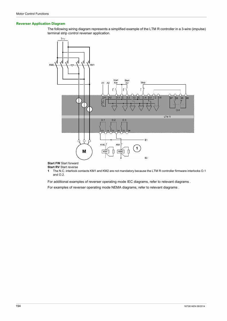
Motor Control Functions
Reverser Application Diagram
The following wiring diagram represents a simplified example of the LTM R controller in a 3-wire (impulse) terminal strip control reverser application.
Start FW Start forwardStart RV Start reverse1 The N.C. interlock contacts KM1 and KM2 are not mandatory because the LTM R controller firmware interlocks O.1
and O.2.
For additional examples of reverser operating mode IEC diagrams, refer to relevant diagrams .
For examples of reverser operating mode NEMA diagrams, refer to relevant diagrams .
194 1672614EN 09/2014
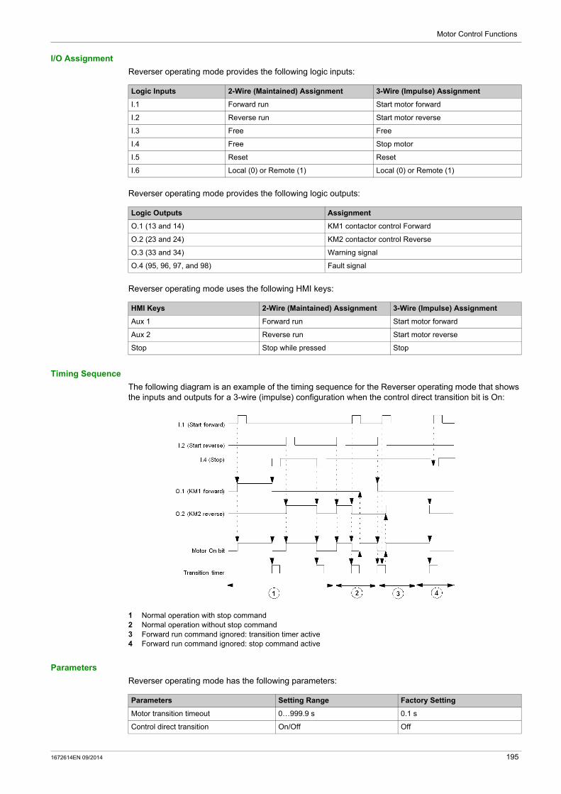
Motor Control Functions
I/O Assignment
Reverser operating mode provides the following logic inputs:
Reverser operating mode provides the following logic outputs:
Reverser operating mode uses the following HMI keys:
Timing Sequence
The following diagram is an example of the timing sequence for the Reverser operating mode that shows the inputs and outputs for a 3-wire (impulse) configuration when the control direct transition bit is On:
1 Normal operation with stop command2 Normal operation without stop command3 Forward run command ignored: transition timer active4 Forward run command ignored: stop command active
Parameters
Reverser operating mode has the following parameters:
Logic Inputs 2-Wire (Maintained) Assignment 3-Wire (Impulse) Assignment
I.1 Forward run Start motor forward
I.2 Reverse run Start motor reverse
I.3 Free Free
I.4 Free Stop motor
I.5 Reset Reset
I.6 Local (0) or Remote (1) Local (0) or Remote (1)
Logic Outputs Assignment
O.1 (13 and 14) KM1 contactor control Forward
O.2 (23 and 24) KM2 contactor control Reverse
O.3 (33 and 34) Warning signal
O.4 (95, 96, 97, and 98) Fault signal
HMI Keys 2-Wire (Maintained) Assignment 3-Wire (Impulse) Assignment
Aux 1 Forward run Start motor forward
Aux 2 Reverse run Start motor reverse
Stop Stop while pressed Stop
Parameters Setting Range Factory Setting
Motor transition timeout 0…999.9 s 0.1 s
Control direct transition On/Off Off
1672614EN 09/2014 195
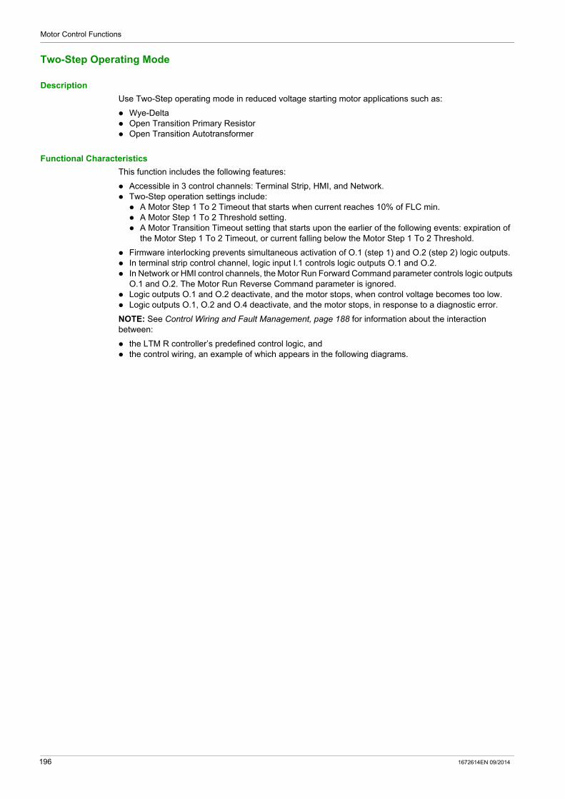
Motor Control Functions
Two-Step Operating Mode
Description
Use Two-Step operating mode in reduced voltage starting motor applications such as:
Wye-Delta Open Transition Primary Resistor Open Transition Autotransformer
Functional Characteristics
This function includes the following features:
Accessible in 3 control channels: Terminal Strip, HMI, and Network. Two-Step operation settings include: A Motor Step 1 To 2 Timeout that starts when current reaches 10% of FLC min. A Motor Step 1 To 2 Threshold setting. A Motor Transition Timeout setting that starts upon the earlier of the following events: expiration of
the Motor Step 1 To 2 Timeout, or current falling below the Motor Step 1 To 2 Threshold.
Firmware interlocking prevents simultaneous activation of O.1 (step 1) and O.2 (step 2) logic outputs. In terminal strip control channel, logic input I.1 controls logic outputs O.1 and O.2. In Network or HMI control channels, the Motor Run Forward Command parameter controls logic outputs
O.1 and O.2. The Motor Run Reverse Command parameter is ignored. Logic outputs O.1 and O.2 deactivate, and the motor stops, when control voltage becomes too low. Logic outputs O.1, O.2 and O.4 deactivate, and the motor stops, in response to a diagnostic error.
NOTE: See Control Wiring and Fault Management, page 188 for information about the interaction between:
the LTM R controller’s predefined control logic, and the control wiring, an example of which appears in the following diagrams.
196 1672614EN 09/2014
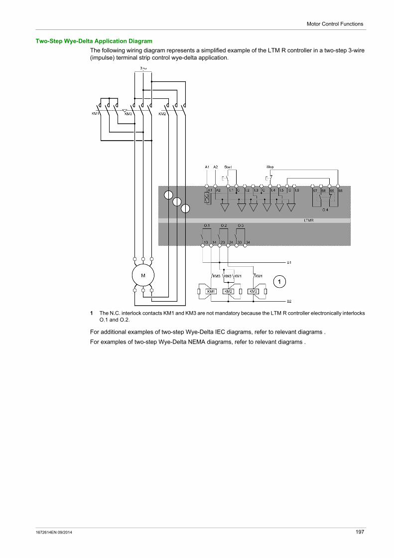
Motor Control Functions
Two-Step Wye-Delta Application Diagram
The following wiring diagram represents a simplified example of the LTM R controller in a two-step 3-wire (impulse) terminal strip control wye-delta application.
1 The N.C. interlock contacts KM1 and KM3 are not mandatory because the LTM R controller electronically interlocks O.1 and O.2.
For additional examples of two-step Wye-Delta IEC diagrams, refer to relevant diagrams .
For examples of two-step Wye-Delta NEMA diagrams, refer to relevant diagrams .
1672614EN 09/2014 197
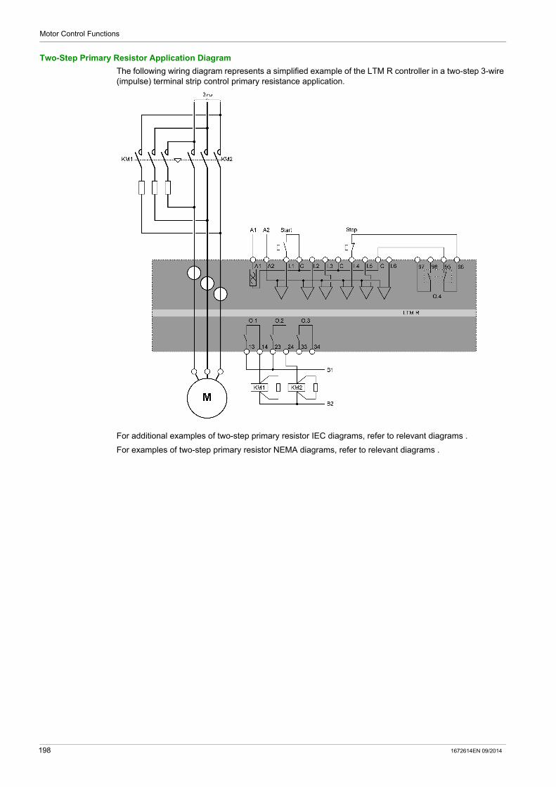
Motor Control Functions
Two-Step Primary Resistor Application Diagram
The following wiring diagram represents a simplified example of the LTM R controller in a two-step 3-wire (impulse) terminal strip control primary resistance application.
For additional examples of two-step primary resistor IEC diagrams, refer to relevant diagrams .
For examples of two-step primary resistor NEMA diagrams, refer to relevant diagrams .
198 1672614EN 09/2014
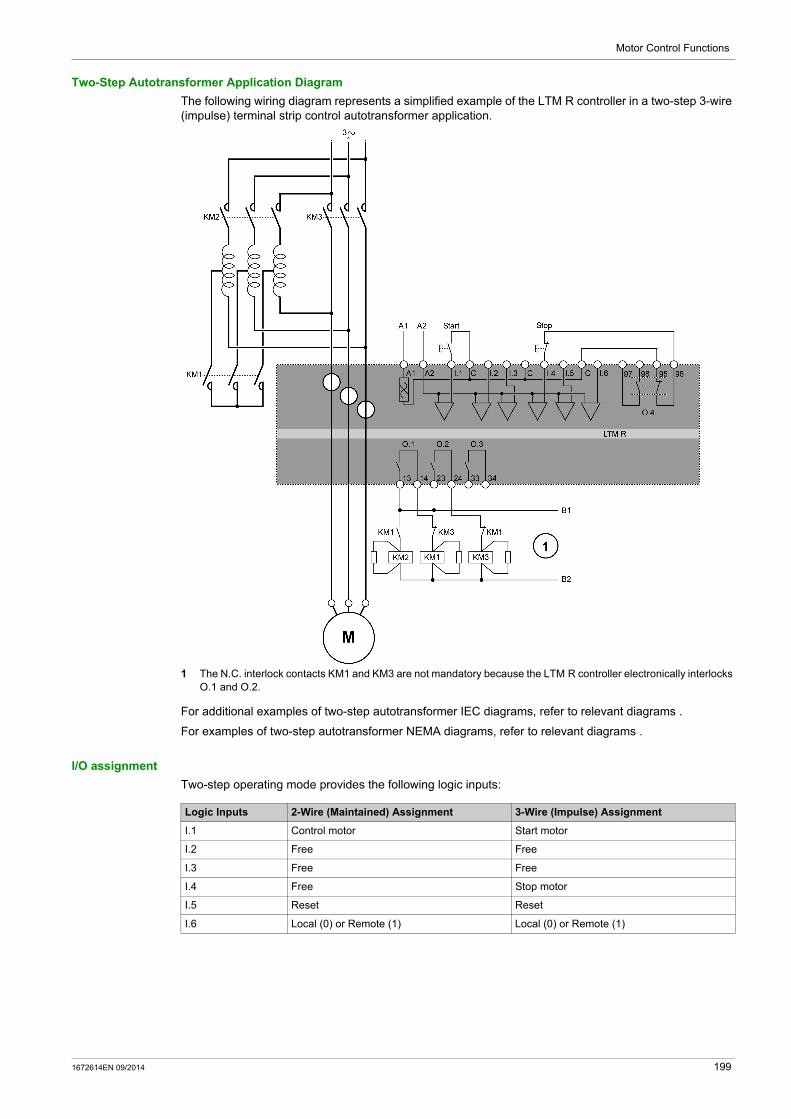
Motor Control Functions
Two-Step Autotransformer Application Diagram
The following wiring diagram represents a simplified example of the LTM R controller in a two-step 3-wire (impulse) terminal strip control autotransformer application.
1 The N.C. interlock contacts KM1 and KM3 are not mandatory because the LTM R controller electronically interlocks O.1 and O.2.
For additional examples of two-step autotransformer IEC diagrams, refer to relevant diagrams .
For examples of two-step autotransformer NEMA diagrams, refer to relevant diagrams .
I/O assignment
Two-step operating mode provides the following logic inputs:
Logic Inputs 2-Wire (Maintained) Assignment 3-Wire (Impulse) Assignment
I.1 Control motor Start motor
I.2 Free Free
I.3 Free Free
I.4 Free Stop motor
I.5 Reset Reset
I.6 Local (0) or Remote (1) Local (0) or Remote (1)
1672614EN 09/2014 199

Motor Control Functions
Two-step operating mode provides the following logic outputs:
Two-step operating mode uses the following HMI keys:
Timing Sequence
The following diagram is an example of the timing sequence for the Two-Step operating mode that shows the inputs and outputs for a 3-wire (impulse) configuration:
1 Normal operation2 Step 1 start3 Step 2 start4 Start command ignored: Stop command active5 Current falling below the Motor Step 1 To 2 Threshold ignored: preceded by expiration of the Motor Step 1 To 2
Timeout.
Parameters
Two-step operating mode has the following parameters:
Logic Outputs Assignment
O.1 (13 and 14) Step 1 contactor control
O.2 (23 and 24) Step 2 contactor control
O.3 (33 and 34) Warning signal
O.4 (95, 96, 97, and 98) Fault signal
HMI Keys 2-Wire (Maintained) Assignment 3-Wire (Impulse) Assignment
Aux 1 Control motor Start motor
Aux 2 Free Free
Stop Stop motor while pressed Stop motor
Parameter Setting Range Factory Setting
Motor step 1 to 2 timeout 0.1…999.9 s 5 s
Motor transition timeout 0…999.9 s 100 ms
Motor step 1 to 2 threshold 20-800 % FLC in 1 % increments 150 % FLC
200 1672614EN 09/2014

Motor Control Functions
Two-Speed Operating Mode
Description
Use Two-Speed operating mode in two-speed motor applications for motor types such as:
Dahlander (consequent pole) Pole Changer
Functional Characteristics
This function includes the following features:
Accessible in 3 control channels: Terminal Strip, HMI, and Network. Firmware interlocking prevents simultaneous activation of O.1 (low speed) and O.2 (high speed) logic
outputs. 2 measures of FLC: FLC1 (Motor Full Load Current Ratio) at low speed FLC2 (Motor High Speed Full Load Current Ratio) at high speed
The LTM R controller can change speed in 2 scenarios: The Control Direct Transition bit is Off: requires a Stop command followed by expiration of the Motor
Transition Timeout. The Control Direct Transition bit is On: automatically transitions from high speed to low speed after
a time-out of the adjustable Motor Transition Timeout.
In terminal strip control channel, logic input I.1 controls logic output O.1, and logic input I.2 controls logic output O.2.
In Network or HMI control channels, when the Motor Run Forward Command parameter is set to 1 and: Motor Low Speed Command is set to 1, logic output O.1 is enabled. Motor Low Speed Command is set to 0, logic output O.2 is enabled.
Logic input I.3 is not used in the control circuit, but can be configured to set a bit in memory. Logic outputs O.1 and O.2 deactivate (and the motor stops) when control voltage becomes too low. Logic outputs O.1, O.2 and O.4 deactivate (and the motor stops) in response to a diagnostic error.
NOTE: See Control Wiring and Fault Management, page 188 for information about the interaction between:
the LTM R controller’s predefined control logic, and the control wiring, an example of which appears in the following diagrams
1672614EN 09/2014 201
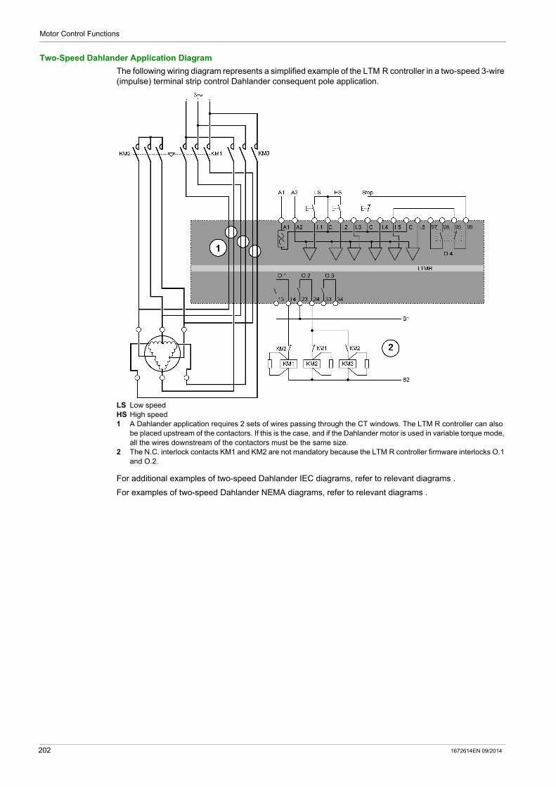
Motor Control Functions
Two-Speed Dahlander Application Diagram
The following wiring diagram represents a simplified example of the LTM R controller in a two-speed 3-wire (impulse) terminal strip control Dahlander consequent pole application.
LS Low speedHS High speed1 A Dahlander application requires 2 sets of wires passing through the CT windows. The LTM R controller can also
be placed upstream of the contactors. If this is the case, and if the Dahlander motor is used in variable torque mode, all the wires downstream of the contactors must be the same size.
2 The N.C. interlock contacts KM1 and KM2 are not mandatory because the LTM R controller firmware interlocks O.1 and O.2.
For additional examples of two-speed Dahlander IEC diagrams, refer to relevant diagrams .
For examples of two-speed Dahlander NEMA diagrams, refer to relevant diagrams .
202 1672614EN 09/2014

Motor Control Functions
Two-Speed Pole-Changing Application Diagram
The following wiring diagram represents a simplified example of the LTM R controller in a two-speed 3-wire (impulse) terminal strip control pole-changing application.
LS Low speedHS High speed1 A pole-changing application requires 2 sets of wires passing through the CT windows. The LTM R controller can
also be placed upstream of the contactors. If this is the case, all the wires downstream of the contactors must be the same size.
2 The N.C. interlock contacts KM1 and KM2 are not mandatory because the LTM R controller firmware interlocks O.1 and O.2.
For additional examples of pole-changing IEC diagrams, refer to relevant diagrams .
For examples of pole-changing NEMA diagrams, refer to relevant diagrams .
I/O Assignment
Two-Speed operating mode provides the following logic inputs:
Logic Inputs 2-Wire (Maintained) Assignment 3-Wire (Impulse) Assignment
I.1 Low speed command Low speed start
I.2 High speed command High speed start
I.3 Free Free
I.4 Free Stop
I.5 Reset Reset
I.6 Local (0) or Remote (1) Local (0) or Remote (1)
1672614EN 09/2014 203

Motor Control Functions
Two-Speed operating mode provides the following logic outputs:
Two-speed operating mode uses the following HMI keys:
Timing Sequence
The following diagram is an example of the timing sequence for the two-speed operating mode that shows the inputs and outputs for a 3-wire (impulse) configuration when the Control Direct Transition bit is On:
1 Normal operation with stop command2 Normal operation without stop command3 Low-speed start command ignored: motor transition timeout active4 Low-speed start command ignored: stop command active
Parameters
The following table lists the parameters associated with the Two-Speed operating mode.
NOTE: The low speed to high speed timer is fixed at 100 ms.
Logic outputs Assignment
O.1 (13 and 14) Low speed control
O.2 (23 and 24) High speed control
O.3 (33 and 34) Warning signal
O.4 (95, 96, 97, and 98) Fault signal
HMI Keys 2-Wire (Maintained) Assignment 3-Wire (Impulse) Assignment
Aux 1 Low speed control Low speed start
Aux 2 High speed control High speed start
Stop Stop the motor Stop the motor
Parameters Setting Range Factory Setting
Motor transition timeout (high speed to low speed) 0…999.9 s 100 ms
Control direct transition On/Off Off
204 1672614EN 09/2014
Motor Control Functions
Custom Operating Mode
Overview
The predefined control and monitoring functions can be adapted for particular needs using the custom logic editor in the TeSys T DTM to: customize the use of results of protection functions change the operation of control and monitoring functions alter the predefined LTM R controller I/O logic
Configuration Files
The configuration of the LTM R controller consists of 2 files:
a configuration file that contains parameter configuration settings a logic file that contains a series of logic commands that manage LTM R controller behavior, including: motor start and stop commands motor transitions between steps, speeds and directions the valid control source and transitions between control sources fault and warning logic for relay outputs 1 and 2, and the HMI terminal strip reset functions PLC and HMI communication loss and fallback load shed rapid cycle starting and stopping LTM R controller diagnostics
When a predefined operating mode is selected, the LTM R controller applies a predefined logic file that permanently resides in the LTM R controller.
When custom operating mode is selected, the LTM R controller uses a customized logic file created in the custom logic editor and downloaded to the LTM R controller from the TeSys T DTM.
1672614EN 09/2014 205
Motor Control Functions
Fault Management and Clear Commands
Section 4.3Fault Management and Clear Commands
Overview
This section describes how the LTM R controller manages the fault handling process, and explains:
how to select a fault reset mode, and controller behavior for each fault reset mode selection.
What Is in This Section?
This section contains the following topics:
Topic Page
Fault Management - Introduction 207
Manual Reset 209
Automatic Reset 211
Remote Reset 214
Fault and Warning Codes 216
LTM R Controller Clear Commands 218
206 1672614EN 09/2014

Motor Control Functions
Fault Management - Introduction
Overview
When the LTM R controller detects a fault condition and activates the appropriate response, the fault becomes latched. Once a fault becomes latched, it remains latched, even if the underlying fault condition is eliminated, until cleared by a reset command.
The setting of the Fault Reset Mode parameter determines how the LTM R controller manages faults. The fault reset mode selections, listed below, are described in the topics that follow:
Manual (see page 209) (Factory setting) Automatic (see page 211) Remote (see page 214)
The fault reset mode cannot be changed while a fault remains active. All faults must be reset before the fault reset mode can be changed.
Fault Reset Methods
A Reset command can be issued using any of the following means:
cycling power reset button on the LTM R controller reset button on the HMI keypad reset command from the HMI engineering tool logic input I.5 a network command automatic reset
Fault Specific Reset Behaviors
The LTM R controller’s response to faults depends on the nature of the fault that has occurred and how the related protection function is configured. For example:
Thermal faults can be reset after the Fault Reset Timeout counts down and the utilized thermal capacity falls below the Fault Reset Threshold level.
If the fault includes a reset timeout setting, the timeout must fully count down before a reset command executes.
Internal device faults can be reset only by cycling power. LTM R controller memory does not retain diagnostic and wiring faults after a power loss, but does retain
all other faults after a power loss. Internal, diagnostic, and wiring faults cannot be automatically reset. All wiring and diagnostic faults can be manually reset by local reset methods. For diagnostic faults, network reset commands are valid only in remote (network) control channel. For wiring faults, network reset commands are not valid in any control channel.
WARNINGRISK OF UNINTENDED OPERATION
When the LTM R controller is operating in 2-wire control with an active Run command, a Reset command will immediately restart the motor.
Failure to follow these instructions can result in death, serious injury, or equipment damage.
1672614EN 09/2014 207
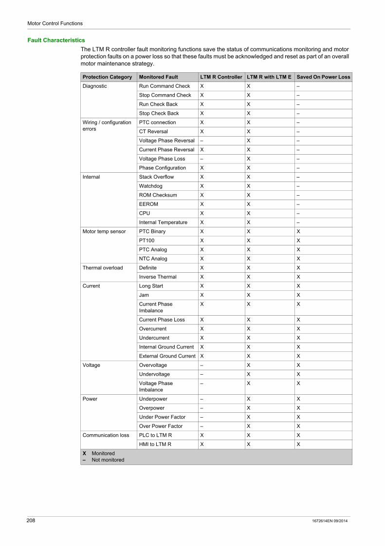
Motor Control Functions
Fault Characteristics
The LTM R controller fault monitoring functions save the status of communications monitoring and motor protection faults on a power loss so that these faults must be acknowledged and reset as part of an overall motor maintenance strategy.
Protection Category Monitored Fault LTM R Controller LTM R with LTM E Saved On Power Loss
Diagnostic Run Command Check X X –
Stop Command Check X X –
Run Check Back X X –
Stop Check Back X X –
Wiring / configuration errors
PTC connection X X –
CT Reversal X X –
Voltage Phase Reversal – X –
Current Phase Reversal X X –
Voltage Phase Loss – X –
Phase Configuration X X –
Internal Stack Overflow X X –
Watchdog X X –
ROM Checksum X X –
EEROM X X –
CPU X X –
Internal Temperature X X –
Motor temp sensor PTC Binary X X X
PT100 X X X
PTC Analog X X X
NTC Analog X X X
Thermal overload Definite X X X
Inverse Thermal X X X
Current Long Start X X X
Jam X X X
Current Phase Imbalance
X X X
Current Phase Loss X X X
Overcurrent X X X
Undercurrent X X X
Internal Ground Current X X X
External Ground Current X X X
Voltage Overvoltage – X X
Undervoltage – X X
Voltage Phase Imbalance
– X X
Power Underpower – X X
Overpower – X X
Under Power Factor – X X
Over Power Factor – X X
Communication loss PLC to LTM R X X X
HMI to LTM R X X X
X Monitored– Not monitored
208 1672614EN 09/2014

Motor Control Functions
Manual Reset
Introduction
When the Fault Reset Mode parameter is set to Manual, the LTM R controller allows resets–usually performed by a person–via a power cycle of the control power or by using a local reset means, including:
Terminal Strip (logic input I.5) Reset button on the LTM R controller Reset commands from the HMI
A manual reset provides on-site personnel the opportunity to inspect the equipment and wiring before performing the reset.
NOTE: A manual reset blocks all reset commands from the LTM R controller’s network port—even when the Control Channel is set to Network.
Manual Reset Methods
The LTM R controller provides the following manual reset methods:
Protection Category Monitored Fault Control Channel
Terminal Strip HMI Network(1)
Diagnostic Run Command Check RB, PC, I.5 RB, PC, I.5 RB, PC, I.5
Stop Command Check RB, PC, I.5 RB, PC, I.5 RB, PC, I.5
Run Check Back RB, PC, I.5 RB, PC, I.5 RB, PC, I.5
Stop Check Back RB, PC, I.5 RB, PC, I.5 RB, PC, I.5
Wiring / configuration errors PTC connection RB, PC, I.5 RB, PC, I.5 RB, PC, I.5
CT Reversal RB, PC, I.5 RB, PC, I.5 RB, PC, I.5
Voltage Phase Reversal RB, PC, I.5 RB, PC, I.5 RB, PC, I.5
Current Phase Reversal RB, PC, I.5 RB, PC, I.5 RB, PC, I.5
Voltage Phase Loss RB, PC, I.5 RB, PC, I.5 RB, PC, I.5
Phase Configuration RB, PC, I.5 RB, PC, I.5 RB, PC, I.5
Internal Stack Overflow PC PC PC
Watchdog PC PC PC
ROM Checksum PC PC PC
EEROM PC PC PC
CPU PC PC PC
Internal Temperature PC PC PC
Motor temp sensor PTC Binary RB, I.5 RB, I.5 RB, I.5
PT100 RB, I.5 RB, I.5 RB, I.5
PTC Analog RB, I.5 RB, I.5 RB, I.5
NTC Analog RB, I.5 RB, I.5 RB, I.5
Thermal overload Definite RB, I.5 RB, I.5 RB, I.5
Inverse Thermal RB, I.5 RB, I.5 RB, I.5
Current Long Start RB, I.5 RB, I.5 RB, I.5
Jam RB, I.5 RB, I.5 RB, I.5
Current Phase Imbalance RB, I.5 RB, I.5 RB, I.5
Current Phase Loss RB, I.5 RB, I.5 RB, I.5
Undercurrent RB, I.5 RB, I.5 RB, I.5
Overcurrent RB, I.5 RB, I.5 RB, I.5
External Ground Current RB, I.5 RB, I.5 RB, I.5
Internal Ground Current RB, I.5 RB, I.5 RB, I.5
RB Test/Reset button on the LTM R controller front face or an HMIPC Power cycle on the LTM R controllerI.5 Set I.5 logic input on the LTM R controller
(1) Remote network reset commands are not allowed even when the LTM R controller is configured for network control channel.
1672614EN 09/2014 209

Motor Control Functions
Voltage Undervoltage RB, I.5 RB, I.5 RB, I.5
Overvoltage RB, I.5 RB, I.5 RB, I.5
Voltage Phase Imbalance RB, I.5 RB, I.5 RB, I.5
Power Underpower RB, I.5 RB, I.5 RB, I.5
Overpower RB, I.5 RB, I.5 RB, I.5
Under Power Factor RB, I.5 RB, I.5 RB, I.5
Over Power Factor RB, I.5 RB, I.5 RB, I.5
Communication loss PLC to LTM R RB, I.5 RB, I.5 RB, I.5
LTM E to LTM R RB, I.5 RB, I.5 RB, I.5
Protection Category Monitored Fault Control Channel
Terminal Strip HMI Network(1)
RB Test/Reset button on the LTM R controller front face or an HMIPC Power cycle on the LTM R controllerI.5 Set I.5 logic input on the LTM R controller
(1) Remote network reset commands are not allowed even when the LTM R controller is configured for network control channel.
210 1672614EN 09/2014

Motor Control Functions
Automatic Reset
Introduction
Setting the Fault Reset Mode parameter to Automatic lets you:
configure the LTM R controller to attempt to reset motor protection and communications faults without the intervention of either a human operator or the remote PLC, for example: for a non-networked LTM R controller installed at a location that is physically remote, or locally hard
to access
configure fault handling for each protection fault group in a manner that is appropriate to the faults in that group: set a different timeout delay permit a different number of reset attempts disable automatic fault resetting
The Fault Reset Mode parameter selection determines the available reset methods.
Each protection fault is included in 1 of 3 auto-reset fault groups, based on the characteristics of that fault, as described below. Each fault group has 2 configurable parameters:
a timeout: the Auto-Reset Group (number 1, 2, or 3) Timeout parameter, and a maximum number of permissible fault resets: the Auto-Reset Attempts Group (number 1, 2, or 3)
Setting parameter
Reset Behavior
After power is cycled, the LTM R controller clears and sets to 0 the values of the following parameters:
Auto-Reset Group (number 1, 2, or 3) Timeout and Auto Reset Group (number 1, 2, or 3) Setting.
On a successful reset, the Number of Resets count is cleared and set to 0. A reset is successful if, after reset, the motor runs for 1 minute without a fault of a type in the designated group.
If the maximum number of automatic resets has been reached and if the last reset has failed, the reset mode turns to Manual. When the motor restarts, the automatic mode parameters are set to 0.
Emergency Restart
Use the Clear Thermal Capacity Level Command, in applications where it is necessary, to clear the Thermal Capacity Level parameter following a Thermal Overload inverse thermal fault. This command permits an emergency restart before the motor has actually cooled.
Number of Resets
Each protection group can be set to manual, 1, 2, 3, 4 or 5.
Select "0" to disable automatic reset of protection fault groups—and require a manual reset—even though the Fault Reset Mode parameter is configured for automatic reset.
Select "5" to enable unlimited auto-reset attempts. After the time delay has expired the LTM R controller continually attempts to reset every fault in that reset group.
WARNINGUNINTENDED EQUIPMENT OPERATION
An auto-reset command may restart the motor if the LTM R controller is used in a 2-wire control circuit.
Equipment operation must conform to local and national safety regulations and codes.
Failure to follow these instructions can result in death, serious injury, or equipment damage.
WARNINGLOSS OF MOTOR PROTECTION
Clearing the thermal capacity level inhibits thermal protection and can cause equipment overheating and fire. Continued operation with inhibited thermal protection must be limited to applications where immediate restart is vital.
Failure to follow these instructions can result in death, serious injury, or equipment damage.
1672614EN 09/2014 211

Motor Control Functions
Auto-Reset Group 1 (AU-G1)
Group 1 faults require a predefined cooling time after the monitored parameter returns to and falls below a predefined threshold. Group 1 faults include Thermal Overload and Motor Temp Sensor faults. The cooling time delay is non-configurable. However, you can:
add to the cooling time delay by setting the Auto-Reset Group 1 Timeout parameter to a value greater than 0, or
disable auto-reset by setting the Auto-Reset Group 1 Timeout parameter to 0
Auto-reset group 1 has the following configurable parameters:
Auto-Reset Group 2 (AU-G2)
Group 2 faults generally do not include a predefined cooling time delay before a reset can be executed, but can be reset as soon as the fault condition clears. Many group 2 faults can result in some motor overheating, depending upon the severity and duration of the fault condition, which in turn depends upon the protection function configuration.
You can add a cooling time delay, if appropriate, by setting the Auto-Reset Group 2 Timeout parameter to a value greater than 0. You may also want to limit the number of reset attempts to prevent premature wear or failure of the equipment.
Auto-reset group 2 has the following configurable parameters:
Auto-Reset Group 3 (AU-G3)
Group 3 faults often apply to equipment monitoring and generally do not require a motor cooling period. These faults can be used to detect equipment conditions–for example, an undercurrent fault that detects the loss of a belt, or an overpower fault that detects an increased loading condition in a mixer. You may want to configure group 3 faults in a way that differs significantly from groups 1 or 2, for example by setting the number of resets to 0, thereby requiring a manual reset after the equipment failure has been discovered and corrected.
Auto-reset group 3 has the following configurable parameters:
Parameters Setting Range Factory Setting
Auto-Reset Attempts Group 1 Setting 0 = manual, 1, 2, 3, 4, 5 = unlimited number of reset attempts
5
Auto-Reset Group 1 Timeout 0...65,535 s 480 s
Parameters Setting Range Factory Setting
Auto-Reset Attempts Group 2 Setting 0 = manual, 1, 2, 3, 4, 5 = unlimited number of reset attempts
0
Auto-Reset Group 2 Timeout 0...65,535 s 1,200 s
Parameters Setting Range Factory Setting
Auto-Reset Attempts Group 3 Setting 0 = manual, 1, 2, 3, 4, 5 = unlimited number of reset attempts
0
Auto-Reset Group 3 Timeout 0...65,535 s 60 s
212 1672614EN 09/2014

Motor Control Functions
Auto-Reset Methods
The LTM R controller allows the following auto-reset methods: RB - Test / Reset button on the LTM R or the HMI PC - Power cycle on the LTM R controller I.5 - Set I.5 logic input on the LTM R NC - Network command Automatic with conditions configured for the protection function group (where AU-GX = AU-G1, AU-G2,
or AU-G3)
The table below lists the possible auto-reset methods for each monitored fault:
Protection Category Monitored Fault Control Channel
Terminal Strip HMI Network
Diagnostic Run Command Check RB, PC, I.5 RB, PC, I.5 RB, PC, I.5, NC
Stop Command Check RB, PC, I.5 RB, PC, I.5 RB, PC, I.5, NC
Run Check Back RB, PC, I.5 RB, PC, I.5 RB, PC, I.5, NC
Stop Check Back RB, PC, I.5 RB, PC, I.5 RB, PC, I.5, NC
Wiring / configuration errors
PTC connection RB, PC, I.5 RB, PC, I.5 RB, PC, I.5
CT Reversal RB, PC, I.5 RB, PC, I.5 RB, PC, I.5
Voltage Phase Reversal RB, PC, I.5 RB, PC, I.5 RB, PC, I.5
Current Phase Reversal RB, PC, I.5 RB, PC, I.5 RB, PC, I.5
Voltage Phase Loss RB, PC, I.5 RB, PC, I.5 RB, PC, I.5
Phase Configuration RB, PC, I.5 RB, PC, I.5 RB, PC, I.5, NC
Internal Stack Overflow PC PC PC
Watchdog PC PC PC
ROM Checksum PC PC PC
EEROM PC PC PC
CPU PC PC PC
Internal Temperature PC PC PC
Motor temp sensor PTC Binary AU-G1 AU-G1 AU-G1
PT100 AU-G1 AU-G1 AU-G1
PTC Analog AU-G1 AU-G1 AU-G1
NTC Analog AU-G1 AU-G1 AU-G1
Thermal overload Definite AU-G1 AU-G1 AU-G1
Inverse Thermal AU-G1 AU-G1 AU-G1
Current Long Start RB, I.5, AU-G2 RB, I.5, AU-G2 RB, I.5, NC, AU-G2
Jam RB, I.5, AU-G2 RB, I.5, AU-G2 RB, I.5, NC, AU-G2
Current Phase Imbalance
RB, I.5, AU-G2 RB, I.5, AU-G2 RB, I.5, NC, AU-G2
Current Phase Loss RB, I.5 RB, I.5 RB, I.5, NC
Undercurrent RB, I.5, AU-G3 RB, I.5, AU-G3 RB, I.5, NC, AU-G3
Overcurrent RB, I.5, AU-G3 RB, I.5, AU-G3 RB, I.5, NC, AU-G3
External Ground Current RB, I.5, AU-G2 RB, I.5, AU-G2 RB, I.5, NC, AU-G2
Internal Ground Current RB, I.5, AU-G2 RB, I.5, AU-G2 RB, I.5, NC, AU-G2
Voltage Undervoltage RB, I.5, AU-G2 RB, I.5, AU-G2 RB, I.5, NC, AU-G2
Overvoltage RB, I.5, AU-G2 RB, I.5, AU-G2 RB, I.5, NC, AU-G2
Voltage Phase Imbalance
RB, I.5, AU-G2 RB, I.5, AU-G2 RB, I.5, NC, AU-G2
Power Underpower RB, I.5, AU-G3 RB, I.5, AU-G3 RB, I.5, NC, AU-G3
Overpower RB, I.5, AU-G3 RB, I.5, AU-G3 RB, I.5, NC, AU-G3
Under Power Factor RB, I.5, AU-G2 RB, I.5, AU-G2 RB, I.5, NC, AU-G2
Over Power Factor RB, I.5, AU-G2 RB, I.5, AU-G2 RB, I.5, NC, AU-G2
Communication Loss PLC to LTM R RB, I.5, AU-G3 RB, I.5, AU-G3 RB, I.5, NC, AU-G3
LTM E to LTM R RB, I.5, AU-G3 RB, I.5, AU-G3 RB, I.5, NC, AU-G3
1672614EN 09/2014 213

Motor Control Functions
Remote Reset
Introduction
Setting the Fault Reset Mode parameter to Remote adds resetting faults from the PLC over the LTM R network port. This provides centralized monitoring and control of equipment installations. The Control channel parameter selection determines the available reset methods.
Both manual reset methods and remote reset methods reset a fault.
Remote Reset Methods
The LTM R controller provides the following remote reset methods:
Protection Category
Monitored Fault Control Channel
Terminal Strip HMI Network
Diagnostic Run Command Check RB, PC, I.5, NC RB, PC, I.5, NC RB, PC, I.5, NC
Stop Command Check RB, PC, I.5, NC RB, PC, I.5, NC RB, PC, I.5, NC
Run Check Back RB, PC, I.5, NC RB, PC, I.5, NC RB, PC, I.5, NC
Stop Check Back RB, PC, I.5, NC RB, PC, I.5, NC RB, PC, I.5, NC
Wiring / configuration errors
PTC connection RB, PC, I.5, NC RB, PC, I.5, NC RB, PC, I.5, NC
CT Reversal RB, PC, I.5, NC RB, PC, I.5, NC RB, PC, I.5, NC
Voltage Phase Reversal RB, PC, I.5, NC RB, PC, I.5, NC RB, PC, I.5, NC
Current Phase Reversal RB, PC, I.5, NC RB, PC, I.5, NC RB, PC, I.5, NC
Voltage Phase Loss RB, PC, I.5, NC RB, PC, I.5, NC RB, PC, I.5, NC
Phase Configuration RB, PC, I.5, NC RB, PC, I.5, NC RB, PC, I.5, NC
Internal Stack Overflow PC PC PC
Watchdog PC PC PC
ROM Checksum PC PC PC
EEROM PC PC PC
CPU PC PC PC
Internal Temperature PC PC PC
Motor temp sensor PTC Binary RB, I.5, NC RB, I.5, NC RB, I.5, NC
PT100 RB, I.5, NC RB, I.5, NC RB, I.5, NC
PTC Analog RB, I.5, NC RB, I.5, NC RB, I.5, NC
NTC Analog RB, I.5, NC RB, I.5, NC RB, I.5, NC
Thermal overload Definite RB, I.5, NC RB, I.5, NC RB, I.5, NC
Inverse Thermal RB, I.5, NC RB, I.5, NC RB, I.5, NC
Current Long Start RB, I.5, NC RB, I.5, NC RB, I.5, NC
Jam RB, I.5, NC RB, I.5, NC RB, I.5, NC
Current Phase Imbalance RB, I.5, NC RB, I.5, NC RB, I.5, NC
Current Phase Loss RB, I.5, NC RB, I.5, NC RB, I.5, NC
Undercurrent RB, I.5, NC RB, I.5, NC RB, I.5, NC
Overcurrent RB, I.5, NC RB, I.5, NC RB, I.5, NC
External Ground Current RB, I.5, NC RB, I.5, NC RB, I.5, NC
Internal Ground Current RB, I.5, NC RB, I.5, NC RB, I.5, NC
Voltage Undervoltage RB, I.5, NC RB, I.5, NC RB, I.5, NC
Overvoltage RB, I.5, NC RB, I.5, NC RB, I.5, NC
Voltage Phase Imbalance RB, I.5, NC RB, I.5, NC RB, I.5, NC
RB Test/Reset button on the LTM R controller front face or the HMIPC Power cycle on the LTM R controllerI.5 Set I.5 logic input on the LTM R controller NC Network command
214 1672614EN 09/2014

Motor Control Functions
Power Underpower RB, I.5, NC RB, I.5, NC RB, I.5, NC
Overpower RB, I.5, NC RB, I.5, NC RB, I.5, NC
Under Power Factor RB, I.5, NC RB, I.5, NC RB, I.5, NC
Over Power Factor RB, I.5, NC RB, I.5, NC RB, I.5, NC
Communication Loss
PLC to LTM R RB, I.5, NC RB, I.5, NC RB, I.5, NC
LTM E to LTM R RB, I.5, NC RB, I.5, NC RB, I.5, NC
Protection Category
Monitored Fault Control Channel
Terminal Strip HMI Network
RB Test/Reset button on the LTM R controller front face or the HMIPC Power cycle on the LTM R controllerI.5 Set I.5 logic input on the LTM R controller NC Network command
1672614EN 09/2014 215
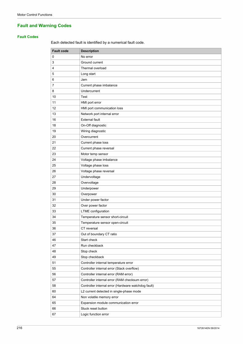
Motor Control Functions
Fault and Warning Codes
Fault Codes
Each detected fault is identified by a numerical fault code.
Fault code Description
0 No error
3 Ground current
4 Thermal overload
5 Long start
6 Jam
7 Current phase imbalance
8 Undercurrent
10 Test
11 HMI port error
12 HMI port communication loss
13 Network port internal error
16 External fault
18 On-Off diagnostic
19 Wiring diagnostic
20 Overcurrent
21 Current phase loss
22 Current phase reversal
23 Motor temp sensor
24 Voltage phase imbalance
25 Voltage phase loss
26 Voltage phase reversal
27 Undervoltage
28 Overvoltage
29 Underpower
30 Overpower
31 Under power factor
32 Over power factor
33 LTME configuration
34 Temperature sensor short-circuit
35 Temperature sensor open-circuit
36 CT reversal
37 Out of boundary CT ratio
46 Start check
47 Run checkback
48 Stop check
49 Stop checkback
51 Controller internal temperature error
55 Controller internal error (Stack overflow)
56 Controller internal error (RAM error)
57 Controller internal error (RAM checksum error)
58 Controller internal error (Hardware watchdog fault)
60 L2 current detected in single-phase mode
64 Non volatile memory error
65 Expansion module communication error
66 Stuck reset button
67 Logic function error
216 1672614EN 09/2014

Motor Control Functions
Warning Codes
Each detected warning is identified by a numerical warning code.
100-104 Network port internal error
109 Network port comm error
111 Faulty device replacement fault
555 Network port configuration error
Fault code Description
Warning code Description
0 No warning
3 Ground current
4 Thermal overload
5 Long start
6 Jam
7 Current phase imbalance
8 Undercurrent
10 HMI port
11 LTM R internal temperature
18 Diagnostic
19 Wiring
20 Overcurrent
21 Current phase loss
23 Motor temp sensor
24 Voltage phase imbalance
25 Voltage phase loss
27 Undervoltage
28 Overvoltage
29 Underpower
30 Overpower
31 Under power factor
32 Over power factor
33 LTM E configuration
46 Start check
47 Run checkback
48 Stop check
49 Stop checkback
109 Network port comm loss
555 Network port configuration
1672614EN 09/2014 217

Motor Control Functions
LTM R Controller Clear Commands
Overview
Clear commands allow the user to clear specific categories of LTM R controller parameters: Clear all parameters Clear the statistics Clear the thermal capacity level Clear the controller settings Clear the network port settings
The Clear commands can be executed from: a PC running SoMove with the TeSys T DTM an HMI device a PLC via the network port
Clear All Command
If you want to change the configuration of the LTM R controller, you may want to clear all existing parameters in order to set new parameters for the controller.
The Clear All Command forces the controller to enter configuration mode. A power-cycle is performed to restart correctly in this mode. This enables the controller to pick up the new values for the cleared parameters.
When you clear all parameters, static characteristics are also lost. Only the following parameters are not cleared after a Clear All Command:
Motor LO1 Closings Count Motor LO2 Closings Count Controller Internal Temperature Max
Clear Statistics Command
Statistics parameters are cleared without the LTM R controller being forced into configuration mode. Static characteristics are preserved.
The following parameters are not cleared after a Clear Statistics Command:
Motor LO1 Closings Count Motor LO2 Closings Count Controller Internal Temperature Max
Clear Thermal Capacity Level Command
The Clear Thermal Capacity Level Command clears the following parameters: Thermal Capacity Level Rapid Cycle Lockout Timeout
Thermal memory parameters are cleared without the controller being forced into configuration mode. Static characteristics are preserved.
NOTE: This bit is writable at any time, even when the motor is running.
For more information about the Clear Thermal Capacity Level Command, see Reset for Emergency Restart, page 108.
Clear Controller Settings Command
The Clear Controller Settings Command restores the LTM R controller protection factory settings (timeouts and thresholds).
The following settings are not cleared by this command:
Controller characteristics Connections (CT, temperature sensor, and I/O settings) Operating mode
Controller setting parameters are cleared without the controller being forced into configuration mode. Static characteristics are preserved.
218 1672614EN 09/2014

Motor Control Functions
Clear Network Port Settings Command
The Clear Network Port Settings Command restores the LTM R controller network port factory settings (address, and so on).
Network port settings are cleared without the controller being forced into configuration mode. Static characteristics are preserved. Only the network communication becomes ineffective.
After the IP addressing parameters are cleared, power must be cycled to the LTM R controller for it .
1672614EN 09/2014 219

Motor Control Functions
220 1672614EN 09/2014
TeSys T DTM for FDT Container
Communication Functions
1672614EN 09/2014
Communication Functions
Chapter 5Communication Functions
This chapter presents the TeSys T communication functions using the network port or HMI port.
What Is in This Chapter?
This chapter contains the following sections:
Section Topic Page
5.1 Configuration of LTM R Ports 222
5.2 Miscellaneous 230
5.3 Using Ethernet Services 236
1672614EN 09/2014 221

Communication Functions
Configuration of LTM R Ports
Section 5.1Configuration of LTM R Ports
Overview
This section describes how to configure the LTM R network port for every communication protocol and the LTM R HMI port.
What Is in This Section?
This section contains the following topics:
Topic Page
Configuration of the LTM R Modbus Network Port 223
Configuration of the LTM R PROFIBUS DP Network Port 224
Configuration of the LTM R CANopen Network Port 225
Configuration of the LTM R DeviceNet Network Port 226
Configuration of the LTM R Ethernet Network Port 227
Configuration of the HMI Port 229
222 1672614EN 09/2014

Communication Functions
Configuration of the LTM R Modbus Network Port
Communication Parameters
Before any communication can start, use the TeSys T DTM or the HMI to configure the Modbus port communication parameters: Network port address setting Network port baud rate setting Network port parity setting Network port comm loss timeout Network port endian setting
Network Port Address Setting
The device address can be set between 1 and 247.
Factory setting is 1, which corresponds to an undefined value.
Network Port Baud Rate Setting
Possible transmission rates are: 1200 Baud 2400 Baud 4800 Baud 9600 Baud 19,200 Baud Autodetection
Factory settings is Autodetection. In Autodetection, the controller is able to adapt its baud rate to that of the master. 19,200 Baud is the first baud rate to be tested.
Network Port Parity Setting
The parity can be selected from: Even Odd None
When Network port baud rate setting is in Autodetection, the controller is able to adapt its parity and stop bit to that of the master. Even parity is the first parity to be tested.
In Autodetection, the parity is set automatically; any previous setting is ignored.
Parity and stop bit behavior is linked:
Network Port Comm Loss Timeout
Network port comm loss timeout is used to determine the timeout value after a loss of communication with the PLC. Range: 1-9,999
Network Port Fallback Setting
Network port fallback setting (see page 74) is used to adjust the fallback mode in case of a loss of communication with the PLC.
Network Port Endian Setting
The Network port endian setting allows to swap the 2 words in a double word. 0 = least significant word first (little endian) 1 = most significant word first (big endian, factory setting)
If the parity is... Then the number of stop bits is...
even or odd 1
none 2
1672614EN 09/2014 223

Communication Functions
Configuration of the LTM R PROFIBUS DP Network Port
Communication Parameters
Use the TeSys T DTM or the HMI to configure the PROFIBUS DP communication parameters: Network port address setting Network port baud rate setting Configuration channel setting
Setting the Node-ID
The Node-ID is the address of the module on the PROFIBUS DP bus. You can assign an address from 1 to 125. The factory setting for the address is 126.
You must set the Node-ID before any communication can begin. Use the TeSys T DTM or the HMI to configure the communication parameter Network Port Address Setting.
NOTE: Address 0 is an invalid value and is not permitted. A return to factory settings command sets the Node-ID to the invalid value 126.
Setting the Baud Rate
Set the baud rate to the only possible speed: 65,535 = Autobaud.
Use the TeSys T DTM or the HMI to configure the communication parameter Network Port Baud Rate Setting.
The factory setting for the Network Port Baud Rate Setting parameter is Autobaud (0xFFFF). Using Autobaud, the LTM R Controller adapts its baud rate to that of the master.
Setting the Configuration Channel
The LTM R configuration can be managed: locally through the HMI port using the TeSys T DTM or the HMI remotely through the network.
To manage the configuration locally, the Config via Network Port Enable parameter must be disabled to prevent an overwrite of the configuration through the network.
To manage the configuration remotely, the Config via Network Port Enable parameter must be enabled (factory setting).
224 1672614EN 09/2014
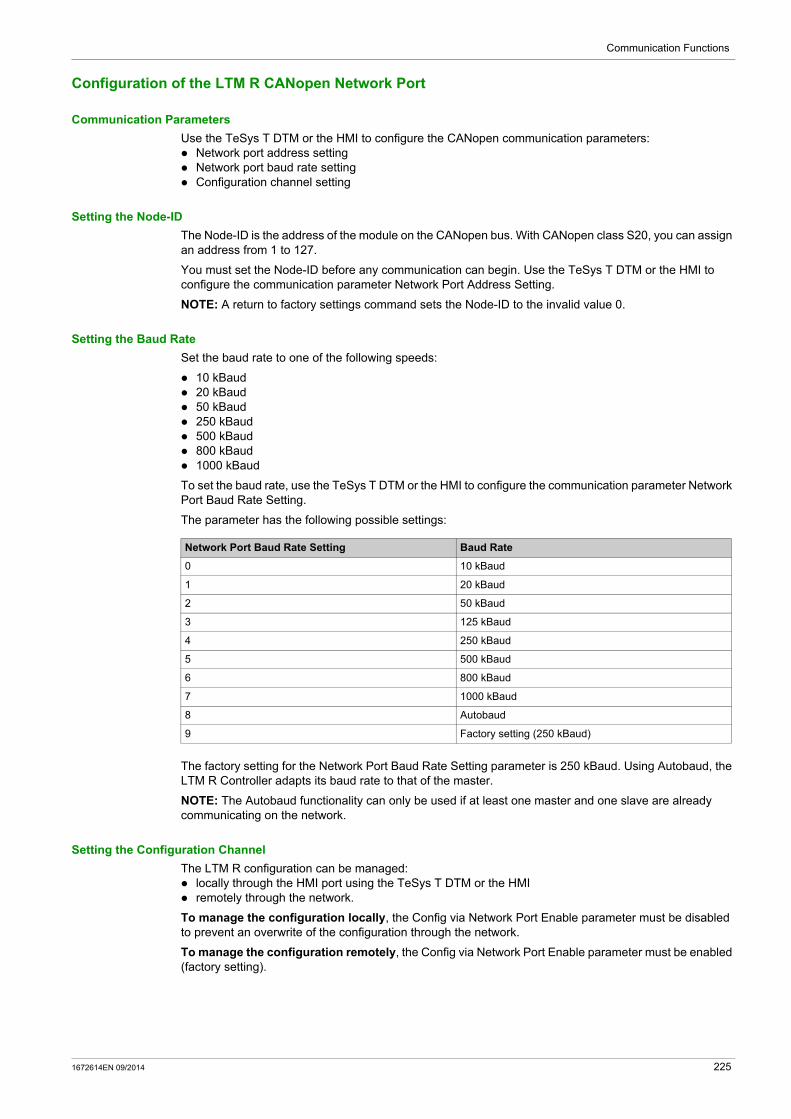
Communication Functions
Configuration of the LTM R CANopen Network Port
Communication Parameters
Use the TeSys T DTM or the HMI to configure the CANopen communication parameters: Network port address setting Network port baud rate setting Configuration channel setting
Setting the Node-ID
The Node-ID is the address of the module on the CANopen bus. With CANopen class S20, you can assign an address from 1 to 127.
You must set the Node-ID before any communication can begin. Use the TeSys T DTM or the HMI to configure the communication parameter Network Port Address Setting.
NOTE: A return to factory settings command sets the Node-ID to the invalid value 0.
Setting the Baud Rate
Set the baud rate to one of the following speeds:
10 kBaud 20 kBaud 50 kBaud 250 kBaud 500 kBaud 800 kBaud 1000 kBaud
To set the baud rate, use the TeSys T DTM or the HMI to configure the communication parameter Network Port Baud Rate Setting.
The parameter has the following possible settings:
The factory setting for the Network Port Baud Rate Setting parameter is 250 kBaud. Using Autobaud, the LTM R Controller adapts its baud rate to that of the master.
NOTE: The Autobaud functionality can only be used if at least one master and one slave are already communicating on the network.
Setting the Configuration Channel
The LTM R configuration can be managed: locally through the HMI port using the TeSys T DTM or the HMI remotely through the network.
To manage the configuration locally, the Config via Network Port Enable parameter must be disabled to prevent an overwrite of the configuration through the network.
To manage the configuration remotely, the Config via Network Port Enable parameter must be enabled (factory setting).
Network Port Baud Rate Setting Baud Rate
0 10 kBaud
1 20 kBaud
2 50 kBaud
3 125 kBaud
4 250 kBaud
5 500 kBaud
6 800 kBaud
7 1000 kBaud
8 Autobaud
9 Factory setting (250 kBaud)
1672614EN 09/2014 225
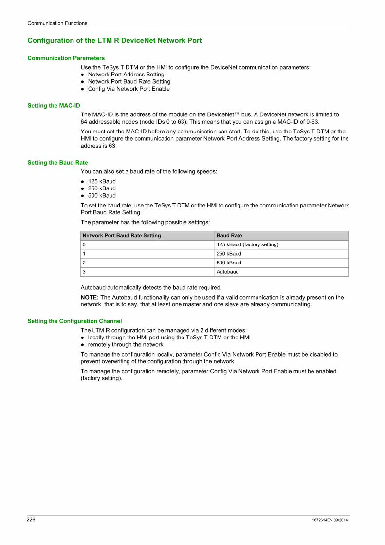
Communication Functions
Configuration of the LTM R DeviceNet Network Port
Communication Parameters
Use the TeSys T DTM or the HMI to configure the DeviceNet communication parameters: Network Port Address Setting Network Port Baud Rate Setting Config Via Network Port Enable
Setting the MAC-ID
The MAC-ID is the address of the module on the DeviceNet™ bus. A DeviceNet network is limited to 64 addressable nodes (node IDs 0 to 63). This means that you can assign a MAC-ID of 0-63.
You must set the MAC-ID before any communication can start. To do this, use the TeSys T DTM or the HMI to configure the communication parameter Network Port Address Setting. The factory setting for the address is 63.
Setting the Baud Rate
You can also set a baud rate of the following speeds:
125 kBaud 250 kBaud 500 kBaud
To set the baud rate, use the TeSys T DTM or the HMI to configure the communication parameter Network Port Baud Rate Setting.
The parameter has the following possible settings:
Autobaud automatically detects the baud rate required.
NOTE: The Autobaud functionality can only be used if a valid communication is already present on the network, that is to say, that at least one master and one slave are already communicating.
Setting the Configuration Channel
The LTM R configuration can be managed via 2 different modes: locally through the HMI port using the TeSys T DTM or the HMI remotely through the network
To manage the configuration locally, parameter Config Via Network Port Enable must be disabled to prevent overwriting of the configuration through the network.
To manage the configuration remotely, parameter Config Via Network Port Enable must be enabled (factory setting).
Network Port Baud Rate Setting Baud Rate
0 125 kBaud (factory setting)
1 250 kBaud
2 500 kBaud
3 Autobaud
226 1672614EN 09/2014

Communication Functions
Configuration of the LTM R Ethernet Network Port
Communication Parameters
Before network port communication can begin, configure the following Ethernet communication services and settings: Master IP address setting Frame type setting Stored IP addressing settings Network port endian setting Faulty device replacement (FDR) service Network Protocol selection Rapid Spanning Tree Protocol (RSTP) SNMP service Communication loss settings Configuration control
NOTE: Only the TeSys T DTM software can configure all of these services and settings. Other HMI devices can configure all settings and all services except SNMP.
Master IP Address Setting
Configure the Ethernet Master IP Address Setting parameter to add the IP address of the client device (see page 237) dedicated to remotely control the motor. This parameter consists of 4 integer values, from 0 to 255, separated by dots (xxx.xxx.xxx.xxx).
Frame Type Setting
Configure the Network Port Frame Type Setting parameter by selecting an Ethernet frame type: Ethernet II (Factory setting) 802.3
IP Addressing Settings
Unique IP address settings must be assigned to the LTM R controller (including an IP address, a subnet mask, and a gateway address) to be able to communicate over an Ethernet network. The positions of the controller’s 2 rotary switches determine the source of the controller’s IP address settings (see page 241), which can be:
a DHCP server a BootP server stored IP address settings
If the controller’s Ones rotary switch is set to Stored IP, the controller will apply its stored IP address settings (see page 242).
To input the LTM R controller’s stored IP address settings, configure the following parameters:
Ethernet IP Address Setting Ethernet Subnet Mask Setting Ethernet Gateway Address Setting
Each of these parameters consists of 4 integer values, from 0 to 255, separated by dots (xxx.xxx.xxx.xxx).
Network Port Endian Setting
The Network port endian setting allows to swap the 2 words in a double word. 0 = least significant word first (little endian) 1 = most significant word first (big endian, factory setting)
Faulty Device Replacement Service
The Faulty Device Replacement (see page 246) (FDR) service stores the LTM R controller’s operating parameters on a remote server and, if the controller fails and is replaced, sends the replacement controller a copy of the original device’s operating parameters.
To insure the server always contains an accurate, updated copy of the controller’s operating parameters, the FDR service can be configured to automatically backup these parameter settings to the FDR server.
1672614EN 09/2014 227
Communication Functions
To enable the automatic backup of the controller’s operating parameters to the FDR server, configure the following parameters:
Network Port FDR Auto Backup Enable parameter. It can be set to: no auto backup automatic backup (copies the parameters from the controller to the FDR server)
Network Port FDR Controller Interval parameter: the time (in seconds) between automatic backup transmissions. Range = 1...65535s Factory setting = 120s
Network Protocol Setting
Select with this parameter the network protocol you want to use: Modbus/TCP EtherNet/IP
Rapid Spanning Tree Protocol
The Rapid Spanning Tree Protocol (RSTP) service manages the state on every port of each device in the local area network (LAN) loop. The RSTP is configured to respond and resolve a communication loss of a device on the network within 50 milliseconds.
NOTE: 16 devices are the maximum connections allowed on the loop network for the 50 milliseconds to be fully efficient.
To enable the Rapid Spanning Tree Protocol (RSTP) service, set the parameter RSTP Disable to No.
SNMP Service
The LTM R controller supports the simple network management protocol (see page 257) (SNMP). The LTM R controller includes a configurable SNMP agent, that can communicate with up to 2 SNMP managers.
NOTE: SNMP parameters can be configured only using the TeSys T DTM software.
Refer to the topic Configuring the SNMP Service (see page 258) for more information about configuring SNMP parameters.
Network Port Comm Loss Settings
Configure the following parameters to determine how the LTM R controller will handle communication loss with the PLC:
Network Port Comm Loss Timeout: the length of time communication with the PLC defined as Master IP must be lost before the controller will trigger a fault or warning. Range = 0...9999 s Increments = 0.01 s Factory setting = 2 s
Network Port Fallback Setting: determines—with the controller’s operating mode (see page 184)—the behavior of logic outputs 1 and 2, when communication with the PLC is lost. For more information, refer to the explanation of the Fallback Condition (see page 74). Values include: Hold Run O.1, O.2 off O.1, O.2 on O.1 on O.2 on
The factory setting is O.1, O.2 off. Network Port Fault Enable: reports a network fault after the Network Port Comm Loss Timeout setting
has expired. Network Port Warning Enable: reports a network warning after the Network Port Comm Loss Timeout
setting has expired.
228 1672614EN 09/2014
Communication Functions
Configuration of the HMI Port
HMI Port
The HMI port is the RJ45 port on the LTM R controller, or on the LTM E expansion module used to connect
the LTM R controller to an HMI device, such as a Magelis® XBT or a TeSys® T LTM CU, or to a PC running SoMove with the TeSys T DTM.
Communication Parameters
Use the TeSys T DTM or the HMI to modify the HMI port communication parameters: HMI port address setting HMI port baud rate setting HMI port parity setting HMI port endian setting
HMI Port Address Setting
The HMI port address can be set between 1 and 247.
Factory setting is 1.
HMI Port Baud Rate Setting
Possible transmission rates are: 4800 Baud 9600 Baud 19,200 Baud (Factory setting)
HMI Port Parity Setting
The parity can be selected from: Even (Factory setting) None
Parity and stop bit behavior is linked:
HMI Port Endian Setting
The HMI port endian setting allows to swap the 2 words in a double word. 0 = least significant word first (little endian) 1 = most significant word first (big endian, factory setting)
HMI Port Fallback Setting
HMI port fallback setting (see page 74) is used to adjust the fallback mode in case of a loss of communication with the PLC.
If the parity is... Then the number of stop bits is...
Even 1
None 2
1672614EN 09/2014 229

Communication Functions
Miscellaneous
Section 5.2Miscellaneous
What Is in This Section?
This section contains the following topics:
Topic Page
User Map Variables 231
E_TeSys T Fast Access Profile Registers 233
EIOS_TeSys T Profile Registers 234
230 1672614EN 09/2014

Communication Functions
User Map Variables
Overview
User Map variables are designed to optimize the access to several non-contiguous registers in one single request.
You can define several read and write areas.
The user map can be defined via: a PC running SoMove with TeSys T DTM a PLC via the network port
User Map Variables
User Map Variables are described below:
The User Map Address group is used to select a list of addresses to read or write. It can be considered as a configuration area.
The User Map Value group is used to read or write values associated to addresses configured in the User Map Address area:
Read or write of register 900 allows to read or write the register address defined in register 800 Read or write of register 901 allows to read or write the register address defined in register 801,...
User map variable groups Modbus/TCP (Register addresses) EtherNet/IP (Object addresses)
User Map addresses 800 - 899 6D : 01 : 01 - 6D : 01 : 64
User Map values 900 - 999 6E : 01 : 01 - 6E : 01 : 64
Modbus/TCP (Register addresses)
EtherNet/IP (Object addresses)
Variable type Read/Write variables
800-898 6D : 01 : 01 - 6D : 01 : 63
Word[99] User map addresses setting
899 6D : 01 : 64 Word (Reserved)
Modbus/TCP (Register addresses)
EtherNet/IP (Object addresses)
Variable type Read/Write variables
900-998 6E : 01 : 01 - 6E : 01 : 63 Word[99] User map values
999 6E : 01 : 64 Word (Reserved)
1672614EN 09/2014 231

Communication Functions
Example of Use
The User Map Address configuration below gives an example of user map address configuration to access non-contiguous registers:
With this configuration, monitoring information is accessible with one single read request through register addresses 900 to 906.
Configuration and command can be written with one single write using register addresses 950 to 952.
Modbus/TCP (Register
addresses)
EtherNet/IP (Object
addresses)
Value configured Read/Write variables
800 6D : 01 : 01 452 Fault register 1
801 6D : 01 : 02 453 Fault register 2
802 6D : 01 : 03 461 Warning register 1
803 6D : 01 : 04 462 Warning register 2
804 6D : 01 : 05 450 Minimum wait time
805 6D : 01 : 06 500 Average current (0.01 A) MSW
806 6D : 01 : 07 501 Average current (0.01 A) LSW
850 6D : 01 : 51 651 HMI display items register 1
851 6D : 01 : 52 654 HMI display items register 2
852 6D : 01 : 53 705 Control register 2
232 1672614EN 09/2014
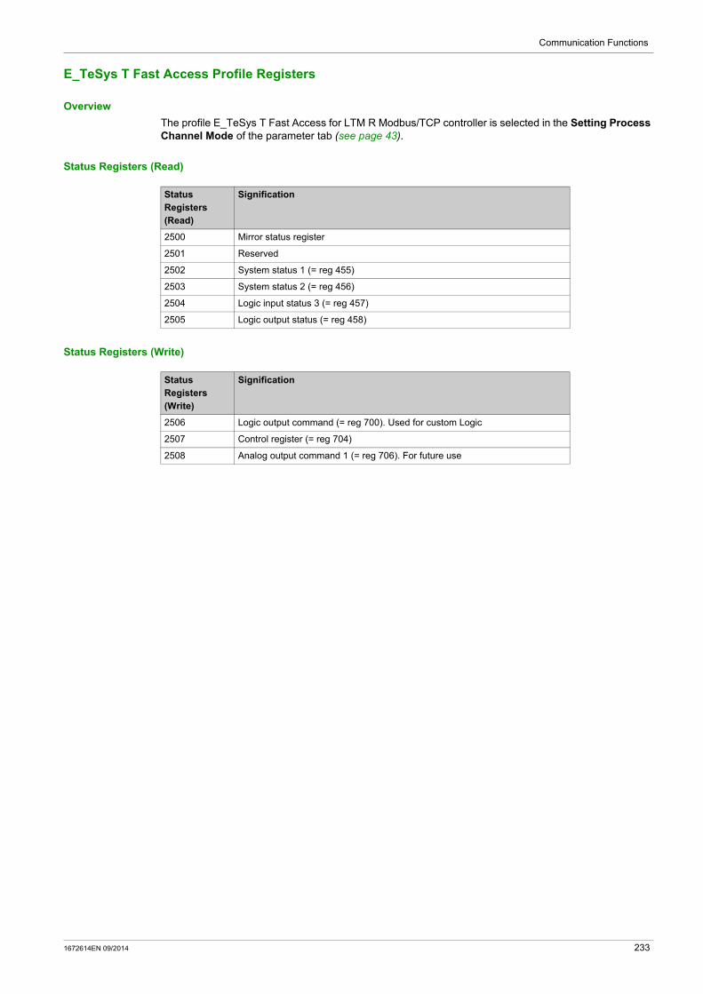
Communication Functions
E_TeSys T Fast Access Profile Registers
Overview
The profile E_TeSys T Fast Access for LTM R Modbus/TCP controller is selected in the Setting Process Channel Mode of the parameter tab (see page 43).
Status Registers (Read)
Status Registers (Write)
Status Registers (Read)
Signification
2500 Mirror status register
2501 Reserved
2502 System status 1 (= reg 455)
2503 System status 2 (= reg 456)
2504 Logic input status 3 (= reg 457)
2505 Logic output status (= reg 458)
Status Registers (Write)
Signification
2506 Logic output command (= reg 700). Used for custom Logic
2507 Control register (= reg 704)
2508 Analog output command 1 (= reg 706). For future use
1672614EN 09/2014 233

Communication Functions
EIOS_TeSys T Profile Registers
Overview
The profile EIOS_TeSys T for LTM R Modbus/TCP controller is selected in the Setting Process Channel Mode of the parameter tab (see page 43).
Status Registers (Read)
Status Registers (Read) Signification
451 Fault code
452 Fault register 1
453 Fault register 2
454 Logic input status 3 (= reg 457)
455 System Status register 1
456 System Status register 1
457 Logic Input status
458 Logic Output status
459 I/O status
460 Warning code
461 Warning register 1
462 Warning register 2
463 Warning register 3
464 Motor Temperature Sensor Degree
465 Thermal Capacity Level
466 Average current Ratio
467 L1 current ratio
468 L2 current ratio
469 L3 current ratio
470 Ground Current ratio
471 Current phase Imbalance
472 Controller: Internal Temperature
473 Controller config checksum
474 Frequency
475 Motor temperature sensor
476 Average voltage
477 L3L1 voltage
478 L1L2 voltage
479 L2L3 voltage
480 Voltage phase Imbalance
481 Power factor
482 Active power
483 Reactive power
484 Auto restart status register
485 Controller: Last power off duration
486 Reserved
487 Reserved
488 Reserved
489 Reserved
490 Network port monitoring register 1
491 Network port monitoring register 2
492 Network port monitoring register 3
493 Network port monitoring register 4
234 1672614EN 09/2014
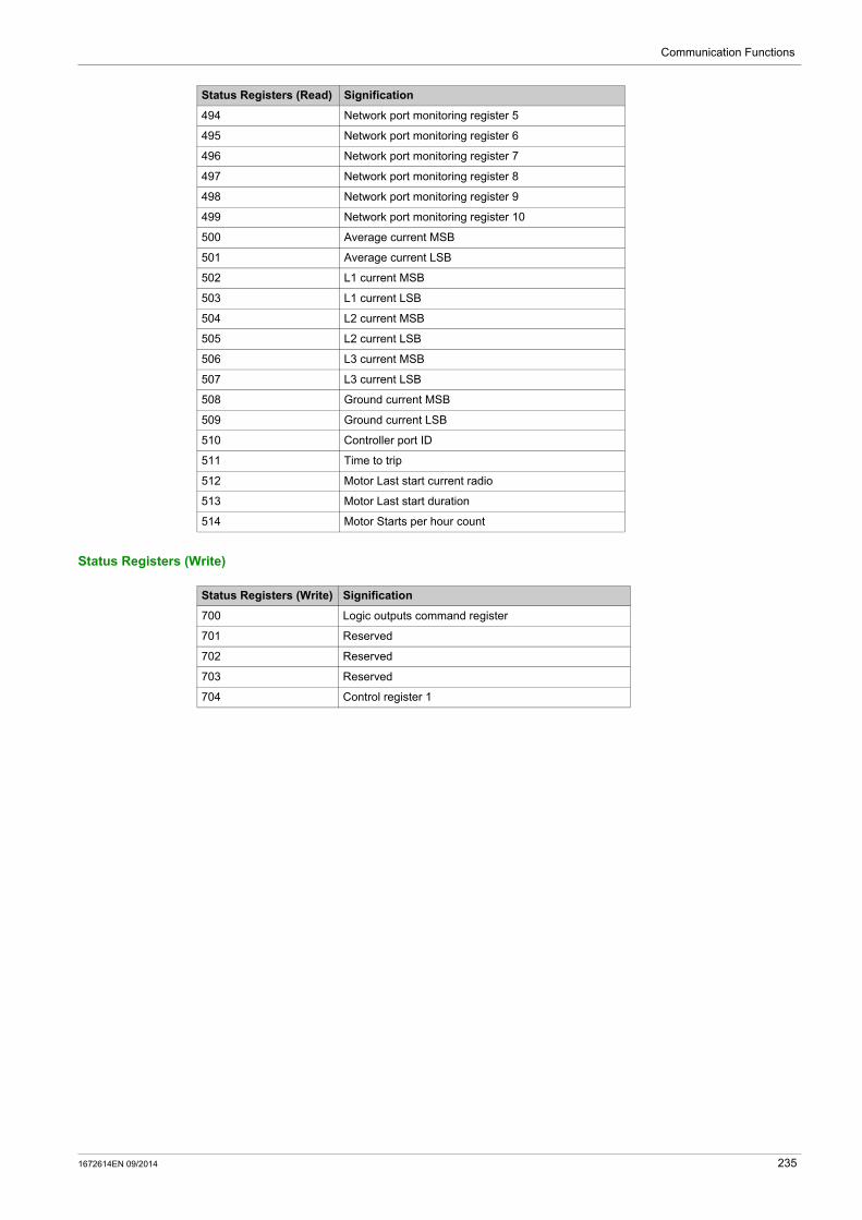
Communication Functions
Status Registers (Write)
494 Network port monitoring register 5
495 Network port monitoring register 6
496 Network port monitoring register 7
497 Network port monitoring register 8
498 Network port monitoring register 9
499 Network port monitoring register 10
500 Average current MSB
501 Average current LSB
502 L1 current MSB
503 L1 current LSB
504 L2 current MSB
505 L2 current LSB
506 L3 current MSB
507 L3 current LSB
508 Ground current MSB
509 Ground current LSB
510 Controller port ID
511 Time to trip
512 Motor Last start current radio
513 Motor Last start duration
514 Motor Starts per hour count
Status Registers (Read) Signification
Status Registers (Write) Signification
700 Logic outputs command register
701 Reserved
702 Reserved
703 Reserved
704 Control register 1
1672614EN 09/2014 235

Communication Functions
Using Ethernet Services
Section 5.3Using Ethernet Services
Overview
This section describes the Ethernet services, and the related Ethernet configuration parameters, supported
by EtherNet/IP and Modbus®/TCP.
NOTE: Changes in parameter settings for any Ethernet service take effect only after a power cycle of the LTM R controller.
(1) For additional information, refer to NEMA ICS 1.1 (latest edition), "Safety Guidelines for the Application, Installation, and Maintenance of Solid State Control".
What Is in This Section?
This section contains the following topics:
WARNINGLOSS OF CONTROL
The designer of any control scheme must consider the potential failure modes of control paths and, for certain critical functions, provide a means to achieve a safe state during and after a path failure. Examples of critical control functions are emergency stop and overtravel stop.
Separate or redundant control paths must be provided for critical control functions. System control paths may include communication links. Consideration must be given to the
implications of anticipated transmission delays or failures of the link.(1)
Each implementation of an LTM R controller must be individually and thoroughly tested for proper operation before being placed into service.
Failure to follow these instructions can result in death, serious injury, or equipment damage.
WARNINGUNEXPECTED RESTART OF THE MOTOR
Check that the PLC application software
considers the change from local to remote control, manages appropriately the motor control commands during those changes. manages appropriately the motor control to avoid contradictory commands from all possible Ethernet
connections
When switching to the Network control channels, depending on the communication protocol configuration, the LTM R controller can take into account the latest known state of the motor control commands issued from the PLC and restart automatically the motor.
Failure to follow these instructions can result in death, serious injury, or equipment damage.
Topic Page
Master IP 237
I/O Scanning Configuration 238
Ethernet Link Management 240
IP Addressing 241
Faulty Device Replacement 246
Rapid Spanning Tree Protocol 251
Ethernet Diagnostics 252
Simple Network Management Protocol 257
236 1672614EN 09/2014

Communication Functions
Master IP
Overview
Each LTM R controller, in its role as communication server, could be configured to recognize another Ethernet device (typically a PLC) as the client device that controls the motor. This device is usually a device that initiates communication to exchange Process Data (control and status). The Master IP is the IP address of this device.
The PLC should continuously maintain at least 1 connection, called a virtual connection or socket, with the communication server.
If all connections between the communication clients and the LTM R server fail, the LTM R controller waits a prescribed time, the Network Port Comm Loss Timeout, for a new connection to be established and messages sent between the PLC and the communication server.
If a connection is not opened and messages are not received, the LTM R controller assumes its fallback state, set by the Network Port Fallback Setting.
Prioritized Master IP Connections with Modbus/TCP
Connections between the LTM R controller and the Modbus client has a priority over connections between the controller and other Ethernet devices.
After the controller has reached its maximum number of 8 simultaneous Modbus connections, the controller must close an existing connection to be able to open a new connection. The controller closes existing connections based on the time of a connection’s most recent transaction, closing the connection whose most recent transaction is the oldest.
However, all connections between the LTM R controller and the Modbus client are preserved. The controller will not close a connection with the Modbus server in order to open a new connection.
Configuring Master IP
To enable connections to be made to a Modbus client, use a configuration tool to configure the following parameters:
WARNINGLOSS OF CONTROL
Configure a server IP on the Ethernet network. Do not use an IP address other than Master IP to send network start and stop commands to the LTM R
controller. Design the Ethernet network to block unauthorized network start and stop commands sent to the
LTM R controller.
Failure to follow these instructions can result in death, serious injury, or equipment damage.
Parameter Setting Range Factory Setting
Ethernet Master IP address setting (3010-3011) Valid Class A, B, and C addresses in the range:0.0.0.0...223.255.255.255
0.0.0.0
Network port comm loss timeout (693) 0...9999 sin increments of 0.01 s
2 s
Network port fallback setting (682) Hold Run O.1, O.2 Off O.1, O.2 On O.1 Off O.2 Off
O.1, O.2 Off
1672614EN 09/2014 237
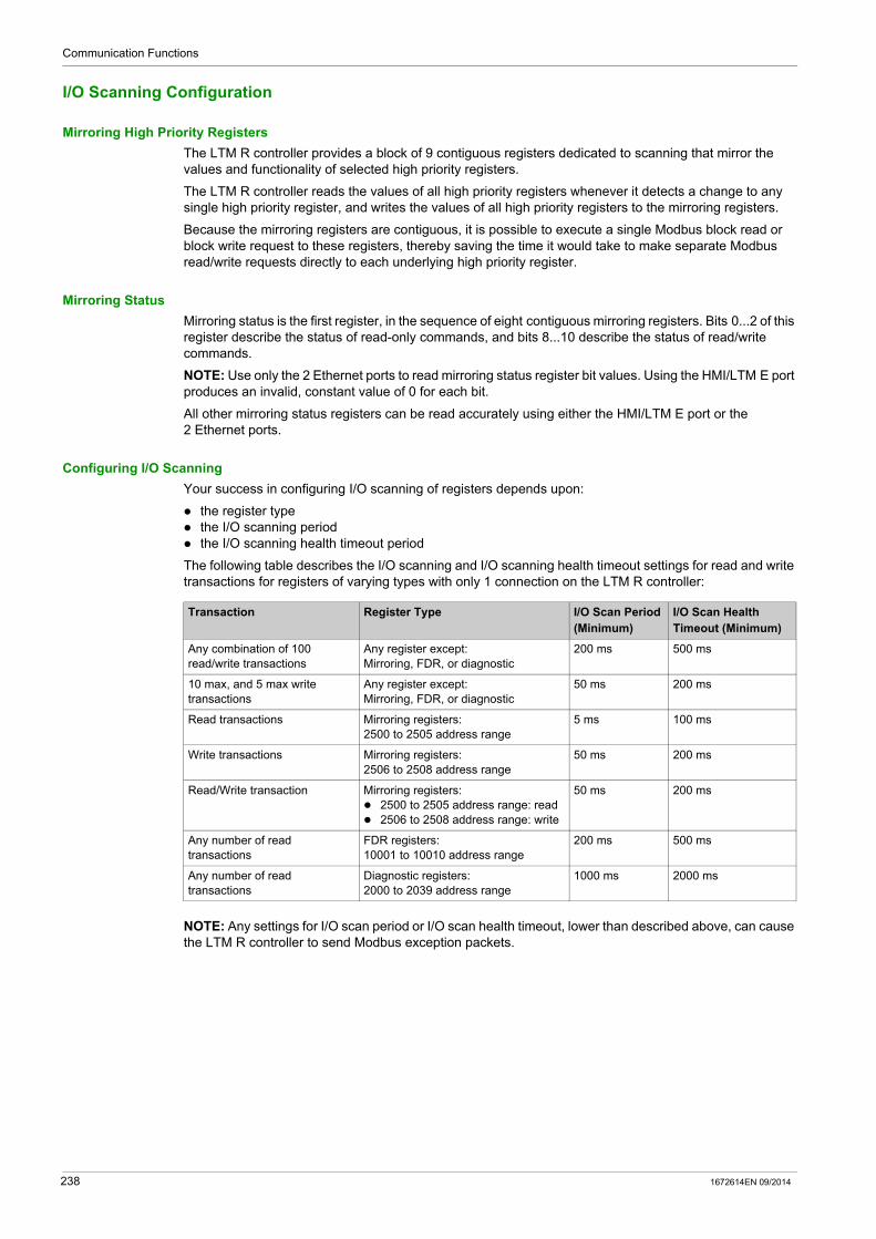
Communication Functions
I/O Scanning Configuration
Mirroring High Priority Registers
The LTM R controller provides a block of 9 contiguous registers dedicated to scanning that mirror the values and functionality of selected high priority registers.
The LTM R controller reads the values of all high priority registers whenever it detects a change to any single high priority register, and writes the values of all high priority registers to the mirroring registers.
Because the mirroring registers are contiguous, it is possible to execute a single Modbus block read or block write request to these registers, thereby saving the time it would take to make separate Modbus read/write requests directly to each underlying high priority register.
Mirroring Status
Mirroring status is the first register, in the sequence of eight contiguous mirroring registers. Bits 0...2 of this register describe the status of read-only commands, and bits 8...10 describe the status of read/write commands.
NOTE: Use only the 2 Ethernet ports to read mirroring status register bit values. Using the HMI/LTM E port produces an invalid, constant value of 0 for each bit.
All other mirroring status registers can be read accurately using either the HMI/LTM E port or the 2 Ethernet ports.
Configuring I/O Scanning
Your success in configuring I/O scanning of registers depends upon:
the register type the I/O scanning period the I/O scanning health timeout period
The following table describes the I/O scanning and I/O scanning health timeout settings for read and write transactions for registers of varying types with only 1 connection on the LTM R controller:
NOTE: Any settings for I/O scan period or I/O scan health timeout, lower than described above, can cause the LTM R controller to send Modbus exception packets.
Transaction Register Type I/O Scan Period (Minimum)
I/O Scan Health Timeout (Minimum)
Any combination of 100 read/write transactions
Any register except: Mirroring, FDR, or diagnostic
200 ms 500 ms
10 max, and 5 max write transactions
Any register except: Mirroring, FDR, or diagnostic
50 ms 200 ms
Read transactions Mirroring registers:2500 to 2505 address range
5 ms 100 ms
Write transactions Mirroring registers:2506 to 2508 address range
50 ms 200 ms
Read/Write transaction Mirroring registers: 2500 to 2505 address range: read 2506 to 2508 address range: write
50 ms 200 ms
Any number of read transactions
FDR registers:10001 to 10010 address range
200 ms 500 ms
Any number of read transactions
Diagnostic registers:2000 to 2039 address range
1000 ms 2000 ms
238 1672614EN 09/2014
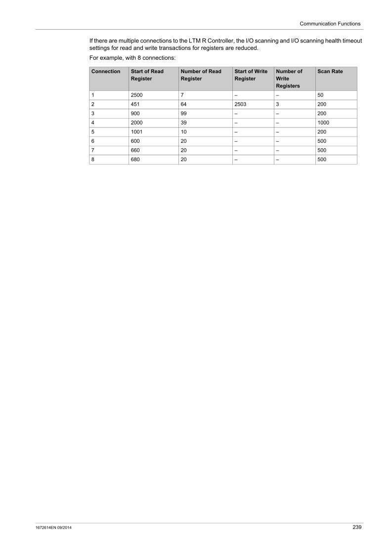
Communication Functions
If there are multiple connections to the LTM R Controller, the I/O scanning and I/O scanning health timeout settings for read and write transactions for registers are reduced.
For example, with 8 connections:
Connection Start of Read Register
Number of Read Register
Start of Write Register
Number of Write Registers
Scan Rate
1 2500 7 – – 50
2 451 64 2503 3 200
3 900 99 – – 200
4 2000 39 – – 1000
5 1001 10 – – 200
6 600 20 – – 500
7 660 20 – – 500
8 680 20 – – 500
1672614EN 09/2014 239
Communication Functions
Ethernet Link Management
Overview
The LTM R controller can receive or provide Ethernet services only if an Ethernet communications link exists. An Ethernet communications link can exist only when a cable connects one of the controller’s network ports to the network. If no network cable connection exists, no Ethernet service can start.
The behavior of the controller is described in each of the following situations:
The LTM R powers up with no network cable connected. A network cable is connected to a previously unconnected controller after startup. All network cables are disconnected from the controller after startup. One (or more) network cables are re-connected to a controller after all network cables had previously
been disconnected.
No link while LTM R is powered up
When the LTM R powers up with no network cable connected, the LTM R
goes into an FDR Fault if the rotary switches are in DHCP position, goes into an FDR Fault for 10s and then clears the fault automatically if the rotary switches are in Stored,
BootP, ClearIP or Disabled positions.
No Link at Startup
When, after controller startup, an Ethernet network cable is initially attached to a previously unconnected controller the controller starts its IP addressing service (see page 241), which obtains IP address settings, validates IP address settings, checks that the obtained IP address settings are not duplicate, assigns the received IP address settings to the controller.
after its IP address settings are assigned, the controller starts the FDR service and obtains its operating parameter settings, then starts its Modbus service.
The time to recover the link and start Ethernet services takes about 1 second.
Link Disconnected After Startup
When all Ethernet network cables are disconnected from the controller after startup:
the FDR service is disabled, all Modbus service connections are re-set, if a Master IP connection exists and: the link cannot be re-established, i.e., the cable is not plugged back into the controller, before the
Network Port Comm Loss Timeout expires, the controller enters its pre-configured fallback state if the LTM R is in Network control,
the link is re-established before the Network Port Comm Loss Timeout expires, the connection to the Master IP is maintained and the controller does not enter its fallback state.
Link Reconnected After Disconnection
When one or more Ethernet network cables are re-attached to the controller, after all network cables had been detached after startup, the controller performs many, but not all, of the same tasks as when there is No Link at Startup (see page 240). Specifically, the controller
presumes the previously obtained IP address settings remain valid, then checks that the IP address settings are not duplicate, re-assigns the IP address settings to the controller.
after the IP address settings are assigned, the controller starts its FDR service and obtains its operating parameter settings, then starts its Modbus service.
The time to recover the link and start Ethernet services takes about 1 second.
240 1672614EN 09/2014
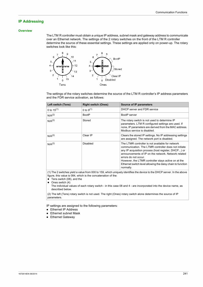
Communication Functions
IP Addressing
Overview
The LTM R controller must obtain a unique IP address, subnet mask and gateway address to communicate over an Ethernet network. The settings of the 2 rotary switches on the front of the LTM R controller determine the source of these essential settings. These settings are applied only on power-up. The rotary switches look like this:
The settings of the rotary switches determine the source of the LTM R controller’s IP address parameters and the FDR service activation, as follows:
IP settings are assigned to the following parameters: Ethernet IP Address Ethernet subnet Mask Ethernet Gateway
Left switch (Tens) Right switch (Ones) Source of IP parameters
0 to 15(1) 0 to 9(1) DHCP server and FDR service
N/A(2) BootP BootP server
N/A(2) Stored The rotary switch is not used to determine IP parameters. LTM R configured settings are used. If none, IP parameters are derived from the MAC address. Modbus service is disabled.
N/A(2) Clear IP Clears the stored IP settings. No IP addressing settings are assigned. The network port is disabled.
N/A(2) Disabled The LTMR controller is not available for network communication. The LTMR controller does not initiate any IP acquisition process (host register, DHCP...) or announcements of IP on the network. Network related errors do not occur.However, the LTMR controller stays active on at the Ethernet switch level allowing the daisy chain to function normally.
(1) The 2 switches yield a value from 000 to 159, which uniquely identifies the device to the DHCP server. In the above figure, this value is 084, which is the concatenation of the: Tens switch (08), and the Ones switch (4)
The individual values of each rotary switch - in this case 08 and 4 - are incorporated into the device name, as described below.
(2) The left (Tens) rotary switch is not used. The right (Ones) rotary switch alone determines the source of IP parameters.
1672614EN 09/2014 241

Communication Functions
Getting IP Parameters from a DHCP Server
To obtain IP parameters from a DHCP server, point each rotary switch to a numerical setting, as follows:
Device Name: The settings of the 2 rotary switches are used to determine each LTM R controller’s device name. The device name consists of a fixed part ("TeSysT") and a dynamic part, composed of:
the two-digit value (00 to 15) of the Tens rotary switch (xx), and
the one-digit value (0 to 9) of the Ones rotary switch (y)
The DCHP server must be pre-configured with the LTM R controller’s device name and its associated IP parameters. When the DHCP server receives the LTM R controller’s broadcast request, it returns:
the LTM R controller’s: IP address subnet mask gateway address
the DHCP server’s IP address
NOTE: While the IP address is not provided by the DHCP server, the TeSys T product declares a major fault network port FDR (Alarm LED steady red).
NOTE: The LTM R controller uses the DHCP server’s IP address during the Faulty Device Replacement (FDR) process (see page 241), when making an FTP or TFTP request for device configuration parameters.
In the figure, above, the device name is: TeSysT084.
NOTE: The DHCP server can provide an IP address to a server device only after the DHCP server has been configured with the Device Name, described above, for a server device.
Getting IP Parameters from a BootP Server
To obtain IP parameters from a BootP server, point the right—Ones—rotary switch to either of the 2 BootP settings. (The left—Tens—rotary switch is not used.) The LTM R controller broadcasts a request for IP parameters to a BootP server, and includes its MAC address in the request.
The BootP server must be pre-configured with the LTM R controller’s MAC address and associated IP parameters. When the BootP server receives the LTM R controller’s broadcast request, it returns to the LTM R controller its:
IP address subnet mask gateway address
NOTE: The Faulty Device Replacement (FDR) service is not available if the LTM R controller is configured to receive IP parameters from a BootP server.
Using Stored IP Parameters
You can configure the LTM R controller to apply IP settings that have been previously configured and stored in the device itself. These stored IP parameters can be configured using your choice of configuration tool.
To apply stored IP parameters set the right–Ones–switch to either of the Stored positions. (The left—Tens—switch is not used.)
The LTM R controller uses as its: IP address: the Ethernet IP Address Setting parameter Subnet mask: the Ethernet Subnet Mask Setting parameters Gateway address: the Ethernet Gateway Address Setting parameter
NOTE: If these parameters are not pre-configured, the LTM R controller cannot apply stored settings, but instead applies default IP parameters, as described below.
NOTE: The FDR service is not available when the LTM R controller is configured to use stored IP parameters.
Step Description
1 Set the left–Tens–switch to a value from 0 to 15, and
2 Set the right–Ones–switch to a value from 0 to 9
242 1672614EN 09/2014

Communication Functions
Configuring Default IP Parameters from the MAC Address
The LTM R controller derives its default IP parameters from its MAC address, (stored in the device’s Ethernet MAC Address parameter). The MAC address is a unique identifier associated with the device’s network interface card (NIC).
As a prerequisite for using the default IP address, all bytes of the configured IP address must be set to zero.
To apply the LTM R controller’s default IP parameters, you must proceed in two steps:
The default IP parameters are generated as follows:
the first 2 byte values of the IP address are always 85.16 the last 2 byte values of the IP address are derived from the last 2 bytes of the MAC address the default subnet mask are always 255.0.0.0 the default gateway is the same as the device’s default IP address
For example, for a device with a hexadecimal MAC address of 0x000054EF1001, the last two bytes are 0x10 and 0x01. These hexadecimal values translate to decimal values of "16" and "01". The default IP parameters for this MAC address are:
IP address: 85.16.16.01 subnet mask: 255.0.0.0 gateway address: 85.16.16.01
NOTE: Both the Faulty Device Replacement (FDR) service and the Modbus service are not available when default IP parameters are used.
Step Action
1 Clear the existing IP address by setting the right—Ones—rotary switch to Clear IP, then cycle power.
2 Apply the stored IP address settings by setting the right—Ones—rotary switch to Stored, then cycle power.
1672614EN 09/2014 243
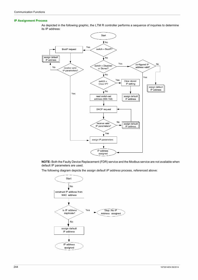
Communication Functions
IP Assignment Process
As depicted in the following graphic, the LTM R controller performs a sequence of inquiries to determine its IP address:
NOTE: Both the Faulty Device Replacement (FDR) service and the Modbus service are not available when default IP parameters are used.
The following diagram depicts the assign default IP address process, referenced above:
244 1672614EN 09/2014
Communication Functions
IP Assignment and STS/NS LED
During the IP address assignment process, while the LTM R is operating normally and is not experiencing an internal fault, the green STS/NS LED may indicate the following conditions:
NOTE: A repeating series of 8 flashes by the STS/NS LED indicates an unrecoverable FDR fault condition. The causes and potential cures for an unrecoverable FDR fault include:
An internal communication failure within the LTM R controller: Cycle power to the controller; if that fails, replace the controller.
An invalid configuration of the Ethernet properties (typically IP address settings or the Master IP address): Verify the IP address parameter settings.
An invalid or corrupt operating parameter file: Transfer a corrected parameter file from the controller to the parameter file server (see page 249). Refer to the topic Handling Unrecoverable FDR Faults for additional information. The transfer of a parameter file to the FDR server is only available with the LTM R controller Ethernet version.
Switch setting(s) STS/NS LED behavior Description
BootP Flashes 5 times, then repeats The controller sent a BootP request, but the BootP server did not deliver valid, unique IP address settings. Waiting for BootP server.
Flashes 5 times, then solid ON The controller sent a BootP request, and the BootP server delivered valid and unique IP address settings.
Stored Solid ON The LTM R controller is configured with valid, unique stored IP address settings.
Flashes 6 times, then repeats No valid, unique IP parameters are stored. Default IP settings are generated using the MAC address.
Clear IP Flashes 2 times, then repeats IP address settings have been cleared. No IP address settings are available. Controller cannot communicate using its Ethernet network ports.
Disabled Solid ON The LTM R controller is configured with valid, unique stored IP address settings.
Flashes 6 times, then repeats No valid, unique IP parameters are stored. Default IP settings are generated using the MAC address.
Left (Tens) switch set to 0-15 (xx)Right (Ones) switch set to 0-9 (y)
Flashes 5 times, then repeats The controller sent a DHCP request for device name (TeSysTxxy), but the DHCP server did not deliver valid, unique IP address settings. Waiting for DHCP server.
Flashes 5 times, then solid ON The controller sent a DHCP request for device name (TeSysTxxy), and the DHCP server delivered valid and unique IP address settings.
1672614EN 09/2014 245

Communication Functions
Faulty Device Replacement
Overview
The FDR service employs a central server to store both the IP addressing parameters and the operating parameters for an LTM R controller. When a failed LTM R controller is replaced, the server automatically configures the replacement LTM R controller with the same IP addressing and operating parameters as the failed controller.
NOTE: The FDR service is available only when the controller’s Ones rotary switch is set to integers. The FDR service is not available when the Ones rotary switch is set to BootP, Stored, Clear IP, or Disabled.
The FDR service includes configurable commands and settings that you can access using your choice of configuration tool. These commands and settings include:
Commands that let you manually: backup the LTM R controller’s operating parameters, by uploading a copy of the device’s parameter
file to the server from the controller, or restore the LTM R controller’s parameters, by downloading a copy of the device’s operating
parameter file from the server to the controller.
Settings that cause the FDR server to automatically synchronize the operating parameter files, in both the LTM R controller and the server, at configurable time intervals. If a difference is detected, a parameter file is sent from the controller to the FDR server (auto backup).
Preconditions to FDR
Before the FDR service can function, the FDR server must be configured with:
the LTM R controller’s network address and related IP addressing parameters, this is done as part of the IP addressing service (see page 241),
a copy of the LTM R controller’s operating parameter file, this can be sent from the controller to the server either manually or automatically, as described below.
FDR and Custom Logic File
The FDR service save custom logic to the operating parameters file if the custom logic file size is lower than 3 kbytes.
If the custom logic file size is bigger than 3 kbytes, only the operating parameters file is saved.
In this case, when you are replacing a device with a custom logic file size bigger than 3 kbytes, the STS/NS LED of the new device flashes 8 times signaling a critical error.
To resolve the error and resume operations:
Step Action
1 Use the TeSys T DTM software to download the configuration
2 Cycle power to the LTM R controller
246 1672614EN 09/2014

Communication Functions
FDR Process
The FDR process consists of 3 parts:
the assignment of IP address settings, a check of the operating parameter file at every LTM R controller startup, if auto-synchronization is enabled, periodic checks of the LTM R controller’s operating parameter file.
These 3 processes are described below:
IP address settings assignment process:
Startup FDR process:
Auto-synchronization FDR process:
Sequence Event
1 Your service personnel uses the rotary switches on the front of the replacement LTM R controller to assign it the same network address (000 to 159) as the failed device.
2 Your service personnel places the replacement LTM R controller on the network.
3 The LTM R controller automatically sends a DHCP request to the server for its IP parameters.
4 The server sends the LTM R controller: IP parameters, including: IP address subnet mask gateway address
the server’s IP address
5 The LTM R controller applies its IP parameters.
Sequence Event
6 If FDR is enabled in the FDR configuration screen:
a The controller sends a request to the FDR server for a copy of the served configuration file.
b The FDR server sends the controller a copy of the served file.
c The controller checks the served file’s version number and size for compatibility with the device. If the served file is compatible, the served file is applied,
not compatible, the controller enters a critical internal error state(1).
Notes: 1. Because the factory setting of FDR Enable is selected, a new LTM R controller always downloads and attempts to apply a served file on initial startup.2. If the downloaded file is empty, the controller will use its local file and send a copy of that file to the server.
If FDR Enable is de-selected: The controller applies the operating parameter file stored in the LTM R controller’s non-volatile memory.
7 The LTM R controller resumes operation.
(1) In the event of an internal critical error, the underlying problem must be resolved and power must be cycled to the controller before operations can resume.
Sequence Event
8 The controller checks the Network Port FDR Auto Backup Period Setting (697) parameter to determine if the FDR auto-synchronization timer has expired.
9 If the timer has: Not expired: No action is taken. Expired: The controller checks the Network Port FDR Auto Backup Enable (690.3) parameter.
10 If the Network Port FDR Auto Backup Enable (690.3) parameter is: Auto backup (1): The controller sends a copy of the local file to the FDR server. No synchro (0): The controller takes no action.
11 The LTM R controller resumes operation.
1672614EN 09/2014 247
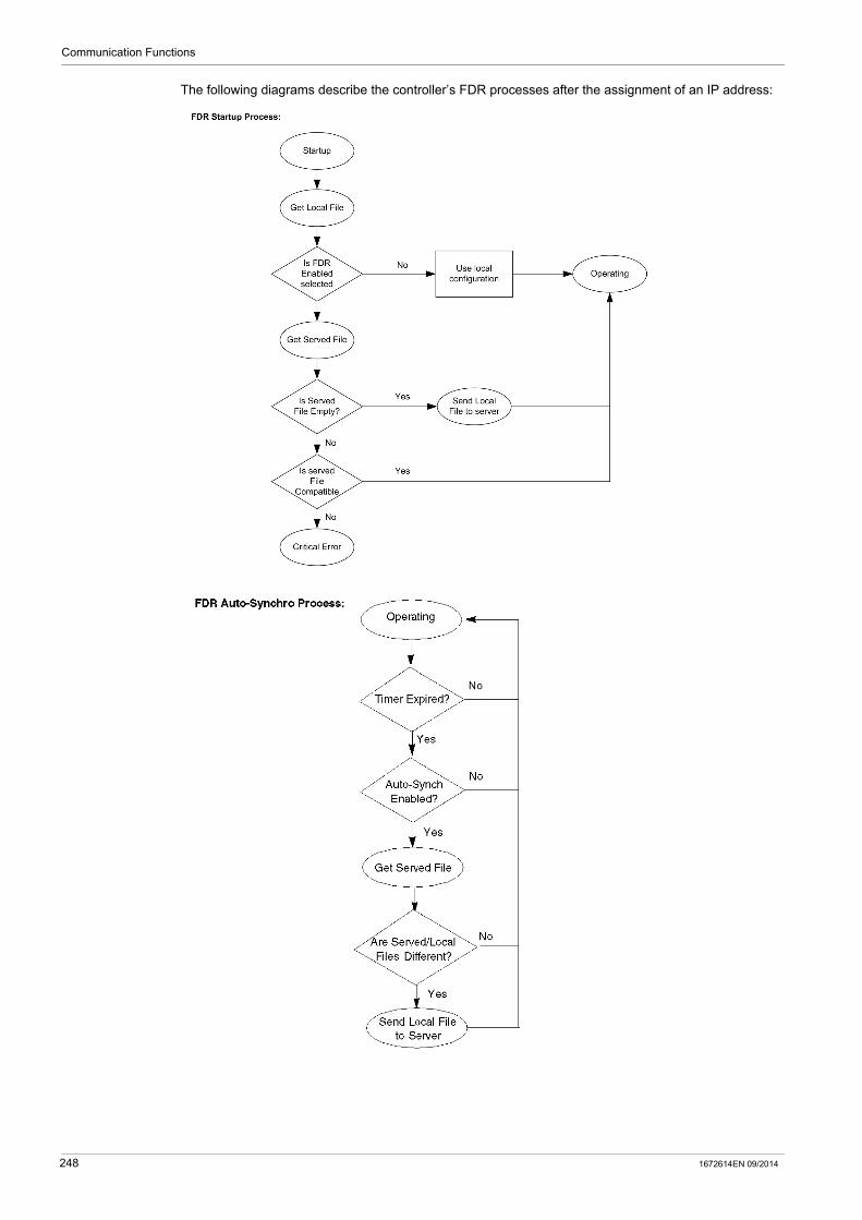
Communication Functions
The following diagrams describe the controller’s FDR processes after the assignment of an IP address:
248 1672614EN 09/2014
Communication Functions
Configuring FDR
The FDR service monitors the operating parameter file maintained in your LTM R controller and compares it against the corresponding operating parameter file stored in the server.
When the FDR service detects a discrepancy between these 2 files:
the Network Port FDR Status (see page 250) parameter is set, and the 2 operating parameter files, 1 in the server, the other in the controller, must be synchronized.
Synchronizing operating parameter files can be performed either automatically or manually, using your choice of configuration tool.
Automatically Backup Settings: By setting the following parameters, you can configure your LTM R controller to automatically synchronize its operating parameters with the FDR server:
NOTE: When automatic synchronization is enabled, it is recommended to set the Network Port FDR Auto Backup Period Setting parameter to a value greater than 120 s.
Manually Backup and Restore Settings: By executing the commands described below, you can manually synchronize the operating parameter files in the controller and server:
NOTE:
If FDR Data Backup Command and FDR Data Restore Command bits are set to 1 simultaneously, an FDR Data Restore Command is proceeded.
FDR Data Restore Command is active whether Config via network is enabled or not. FDR Data Restore Command cannot be done while the LTM R detects line currents. Any time the LTM R controller configuration changes, you should manually backup the new
configuration file to the server by clicking Device → File transfert → backup command.
Parameter Name Description
Network Port FDR Auto Backup Enable Use this setting to enable/disable automatic synchronization of the operating parameter files. Selections are: No auto backup: Automatic file synchronization is turned OFF
(parameter = 0). Auto backup: Automatic file synchronization is turned ON, and
the file in the controller will be copied to the server in case of discrepancy (parameter = 1).
Network Port FDR Auto Backup Period Setting
The frequency, in seconds, between comparisons of the parameter file in the controller against the parameter file stored in the server. Range = 1...65535 s Increments = 1 s Factory setting = 120 s
Command Name Description
FDR Data Backup Command Copies the operating parameter file in the controller to the server.
FDR Data Restore Command Copies the operating parameter file in the server to the controller.
1672614EN 09/2014 249
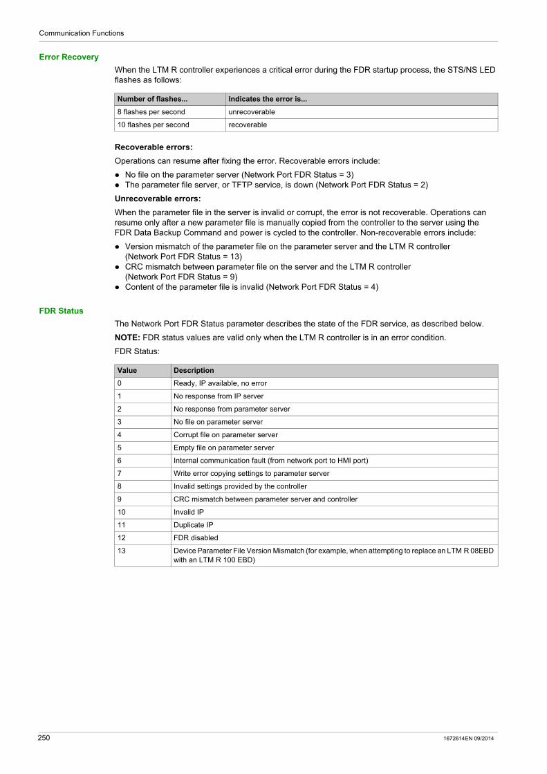
Communication Functions
Error Recovery
When the LTM R controller experiences a critical error during the FDR startup process, the STS/NS LED flashes as follows:
Recoverable errors:
Operations can resume after fixing the error. Recoverable errors include:
No file on the parameter server (Network Port FDR Status = 3) The parameter file server, or TFTP service, is down (Network Port FDR Status = 2)
Unrecoverable errors:
When the parameter file in the server is invalid or corrupt, the error is not recoverable. Operations can resume only after a new parameter file is manually copied from the controller to the server using the FDR Data Backup Command and power is cycled to the controller. Non-recoverable errors include:
Version mismatch of the parameter file on the parameter server and the LTM R controller (Network Port FDR Status = 13)
CRC mismatch between parameter file on the server and the LTM R controller (Network Port FDR Status = 9)
Content of the parameter file is invalid (Network Port FDR Status = 4)
FDR Status
The Network Port FDR Status parameter describes the state of the FDR service, as described below.
NOTE: FDR status values are valid only when the LTM R controller is in an error condition.
FDR Status:
Number of flashes... Indicates the error is...
8 flashes per second unrecoverable
10 flashes per second recoverable
Value Description
0 Ready, IP available, no error
1 No response from IP server
2 No response from parameter server
3 No file on parameter server
4 Corrupt file on parameter server
5 Empty file on parameter server
6 Internal communication fault (from network port to HMI port)
7 Write error copying settings to parameter server
8 Invalid settings provided by the controller
9 CRC mismatch between parameter server and controller
10 Invalid IP
11 Duplicate IP
12 FDR disabled
13 Device Parameter File Version Mismatch (for example, when attempting to replace an LTM R 08EBD with an LTM R 100 EBD)
250 1672614EN 09/2014

Communication Functions
Rapid Spanning Tree Protocol
Overview
The Rapid Spanning Tree Protocol (RSTP) service manages the state on every port of each device in the local area network (LAN) loop. The RSTP is configured to respond and resolve a communication loss of a device on the network within 50 milliseconds.
NOTE: 16 devices are the maximum connections allowed on the loop network for the 50 milliseconds to be fully efficient.
Discovery Procedure
Discovery is an automated connection to a device with an unknown IP address, using a direct PC connection and a web page access interface.
Discovery only operates on MS Windows Vista, 7 and 8 operating systems.
NOTE: If the product cannot be detected, retry the procedure with the antivirus deactivated. Do not forget to restart the antivirus when finished.
Step Automated Action
1 Stop the antivirus on the PC that is connected to the TeSys T.
2 Connect the PC to the TeSys T using a RJ45 cable.
3 Open Windows Explorer Expand Network to view all network connections The Connected device should appear in the list within a few seconds
4 Double-click the connected TeSys T.To find the name of TeSys T: TeSys T is not configured in DHCP mode: TeSysT-XXYYZZ with XXYYZZ the last 3 bytes of
MAC address. TeSys T is configured in DHCP mode TeSysTXYZ with XY the position of Tens rotary switch
and Z the position of Ones rotary switch.
5 Access the TeSys T in the webpage interface.
1672614EN 09/2014 251
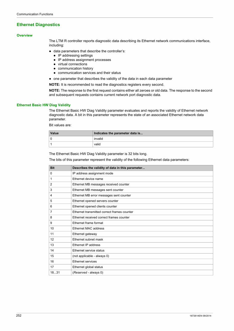
Communication Functions
Ethernet Diagnostics
Overview
The LTM R controller reports diagnostic data describing its Ethernet network communications interface, including:
data parameters that describe the controller’s: IP addressing settings IP address assignment processes virtual connections communication history communication services and their status
one parameter that describes the validity of the data in each data parameter
NOTE: It is recommended to read the diagnostics registers every second.
NOTE: The response to the first request contains either all zeroes or old data. The response to the second and subsequent requests contains current network port diagnostic data.
Ethernet Basic HW Diag Validity
The Ethernet Basic HW Diag Validity parameter evaluates and reports the validity of Ethernet network diagnostic data. A bit in this parameter represents the state of an associated Ethernet network data parameter.
Bit values are:
The Ethernet Basic HW Diag Validity parameter is 32 bits long.
The bits of this parameter represent the validity of the following Ethernet data parameters:
Value Indicates the parameter data is...
0 invalid
1 valid
Bit Describes the validity of data in this parameter...
0 IP address assignment mode
1 Ethernet device name
2 Ethernet MB messages received counter
3 Ethernet MB messages sent counter
4 Ethernet MB error messages sent counter
5 Ethernet opened servers counter
6 Ethernet opened clients counter
7 Ethernet transmitted correct frames counter
8 Ethernet received correct frames counter
9 Ethernet frame format
10 Ethernet MAC address
11 Ethernet gateway
12 Ethernet subnet mask
13 Ethernet IP address
14 Ethernet service status
15 (not applicable - always 0)
16 Ethernet services
17 Ethernet global status
18...31 (Reserved - always 0)
252 1672614EN 09/2014
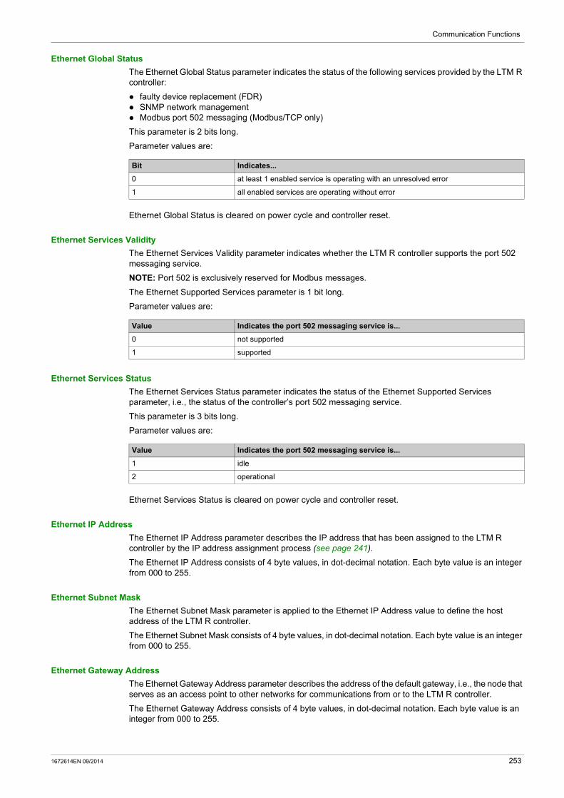
Communication Functions
Ethernet Global Status
The Ethernet Global Status parameter indicates the status of the following services provided by the LTM R controller:
faulty device replacement (FDR) SNMP network management Modbus port 502 messaging (Modbus/TCP only)
This parameter is 2 bits long.
Parameter values are:
Ethernet Global Status is cleared on power cycle and controller reset.
Ethernet Services Validity
The Ethernet Services Validity parameter indicates whether the LTM R controller supports the port 502 messaging service.
NOTE: Port 502 is exclusively reserved for Modbus messages.
The Ethernet Supported Services parameter is 1 bit long.
Parameter values are:
Ethernet Services Status
The Ethernet Services Status parameter indicates the status of the Ethernet Supported Services parameter, i.e., the status of the controller’s port 502 messaging service.
This parameter is 3 bits long.
Parameter values are:
Ethernet Services Status is cleared on power cycle and controller reset.
Ethernet IP Address
The Ethernet IP Address parameter describes the IP address that has been assigned to the LTM R controller by the IP address assignment process (see page 241).
The Ethernet IP Address consists of 4 byte values, in dot-decimal notation. Each byte value is an integer from 000 to 255.
Ethernet Subnet Mask
The Ethernet Subnet Mask parameter is applied to the Ethernet IP Address value to define the host address of the LTM R controller.
The Ethernet Subnet Mask consists of 4 byte values, in dot-decimal notation. Each byte value is an integer from 000 to 255.
Ethernet Gateway Address
The Ethernet Gateway Address parameter describes the address of the default gateway, i.e., the node that serves as an access point to other networks for communications from or to the LTM R controller.
The Ethernet Gateway Address consists of 4 byte values, in dot-decimal notation. Each byte value is an integer from 000 to 255.
Bit Indicates...
0 at least 1 enabled service is operating with an unresolved error
1 all enabled services are operating without error
Value Indicates the port 502 messaging service is...
0 not supported
1 supported
Value Indicates the port 502 messaging service is...
1 idle
2 operational
1672614EN 09/2014 253
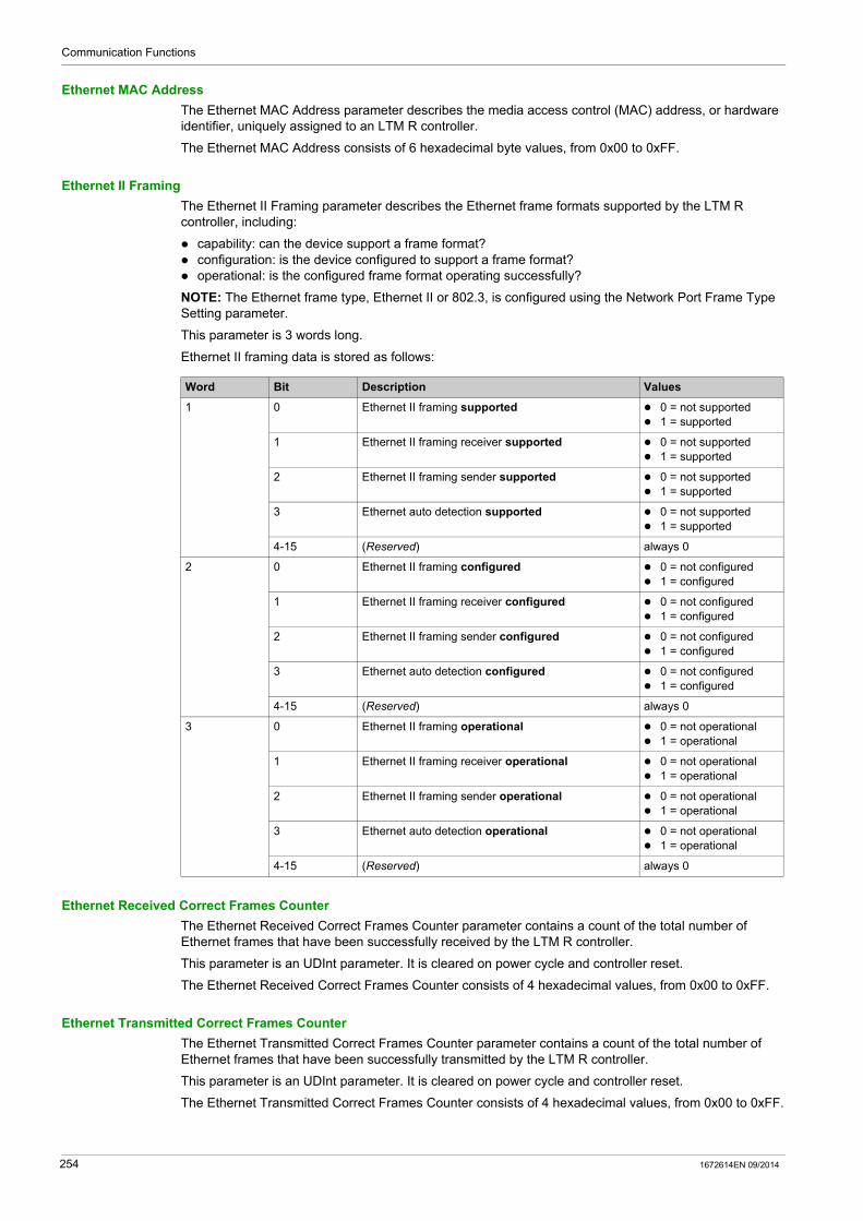
Communication Functions
Ethernet MAC Address
The Ethernet MAC Address parameter describes the media access control (MAC) address, or hardware identifier, uniquely assigned to an LTM R controller.
The Ethernet MAC Address consists of 6 hexadecimal byte values, from 0x00 to 0xFF.
Ethernet II Framing
The Ethernet II Framing parameter describes the Ethernet frame formats supported by the LTM R controller, including:
capability: can the device support a frame format? configuration: is the device configured to support a frame format? operational: is the configured frame format operating successfully?
NOTE: The Ethernet frame type, Ethernet II or 802.3, is configured using the Network Port Frame Type Setting parameter.
This parameter is 3 words long.
Ethernet II framing data is stored as follows:
Ethernet Received Correct Frames Counter
The Ethernet Received Correct Frames Counter parameter contains a count of the total number of Ethernet frames that have been successfully received by the LTM R controller.
This parameter is an UDInt parameter. It is cleared on power cycle and controller reset.
The Ethernet Received Correct Frames Counter consists of 4 hexadecimal values, from 0x00 to 0xFF.
Ethernet Transmitted Correct Frames Counter
The Ethernet Transmitted Correct Frames Counter parameter contains a count of the total number of Ethernet frames that have been successfully transmitted by the LTM R controller.
This parameter is an UDInt parameter. It is cleared on power cycle and controller reset.
The Ethernet Transmitted Correct Frames Counter consists of 4 hexadecimal values, from 0x00 to 0xFF.
Word Bit Description Values
1 0 Ethernet II framing supported 0 = not supported 1 = supported
1 Ethernet II framing receiver supported 0 = not supported 1 = supported
2 Ethernet II framing sender supported 0 = not supported 1 = supported
3 Ethernet auto detection supported 0 = not supported 1 = supported
4-15 (Reserved) always 0
2 0 Ethernet II framing configured 0 = not configured 1 = configured
1 Ethernet II framing receiver configured 0 = not configured 1 = configured
2 Ethernet II framing sender configured 0 = not configured 1 = configured
3 Ethernet auto detection configured 0 = not configured 1 = configured
4-15 (Reserved) always 0
3 0 Ethernet II framing operational 0 = not operational 1 = operational
1 Ethernet II framing receiver operational 0 = not operational 1 = operational
2 Ethernet II framing sender operational 0 = not operational 1 = operational
3 Ethernet auto detection operational 0 = not operational 1 = operational
4-15 (Reserved) always 0
254 1672614EN 09/2014

Communication Functions
Ethernet Opened Clients Counter
The Ethernet Opened Clients Counter parameter contains a count of the number of open TCP client connections. It applies only to devices with TCP clients.
This parameter is an UInt parameter. It is cleared on power cycle and controller reset.
The Ethernet Opened Clients Counter consists of 2 hexadecimal values, from 0x00 to 0xFF.
Ethernet Opened Servers Counter
The Ethernet Opened Servers Counter parameter contains a count of the number of open TCP server connections. It applies only to devices with TCP servers.
This parameter is an UInt parameter. It is cleared on power cycle and controller reset.
The Ethernet Opened Servers Counter consists of 2 hexadecimal values, from 0x00 to 0xFF.
Ethernet MB Error Messages Sent Counter
The Ethernet MB Error Messages Sent Counter parameter contains a count of the number of:
EtherNet/IP or Modbus/TCP request packets with errors in the header that have been received by this LTM R controller (does not count errors in the data portion of EtherNet/IP or Modbus/TCP request packets)
EtherNet/IP or Modbus/TCP exceptions due to incorrect combination of physical port and Unit ID
This parameter is an UDInt parameter. It is cleared on power cycle and controller reset.
Ethernet MB Messages Sent Counter
The Ethernet MB Messages Sent Counter parameter contains the total number of Modbus messages, excluding Modbus error messages, that have been sent by this LTM R controller.
This parameter is an UDInt parameter. It is cleared on power cycle and controller reset.
Ethernet MB Messages Received Counter
The Ethernet MB Messages Received Counter parameter contains the total number of Modbus messages that have been received by this LTM R controller.
This parameter is an UDInt parameter. It is cleared on power cycle and controller reset.
Ethernet Device Name
The Ethernet Device Name parameter contains the 16 character string used to identify the LTM R controller.
This parameter is 16 bytes long.
Ethernet IP Assignment Capability
The Ethernet IP Assignment Capability parameter describes the available IP addressing sources for the LTM R controller. Up to 4 different IP addressing sources can be described.
This parameter is 4 bits long.
The Ethernet IP Assignment Capability parameter stores data as follows:
Bit IP addressing source... Values
0 A DHCP server, using the device name set by the 2 rotary switches 0 = not available 1 = available
1 Derived from the MAC address. The Ones rotary switch is set to BootP, but no IP address was received from the server.
0 = not available 1 = available
2 Derived from the MAC address. Both rotary switches are set to integers, but no IP address was received from the DHCP server.
0 = not available 1 = available
3 The stored configuration parameters: Ethernet IP Address Setting Ethernet Subnet Mask Setting Ethernet Gateway Address Setting
0 = not available 1 = available
1672614EN 09/2014 255
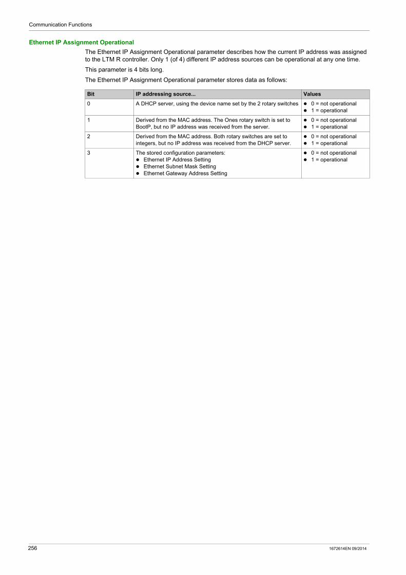
Communication Functions
Ethernet IP Assignment Operational
The Ethernet IP Assignment Operational parameter describes how the current IP address was assigned to the LTM R controller. Only 1 (of 4) different IP address sources can be operational at any one time.
This parameter is 4 bits long.
The Ethernet IP Assignment Operational parameter stores data as follows:
Bit IP addressing source... Values
0 A DHCP server, using the device name set by the 2 rotary switches 0 = not operational 1 = operational
1 Derived from the MAC address. The Ones rotary switch is set to BootP, but no IP address was received from the server.
0 = not operational 1 = operational
2 Derived from the MAC address. Both rotary switches are set to integers, but no IP address was received from the DHCP server.
0 = not operational 1 = operational
3 The stored configuration parameters: Ethernet IP Address Setting Ethernet Subnet Mask Setting Ethernet Gateway Address Setting
0 = not operational 1 = operational
256 1672614EN 09/2014

Communication Functions
Simple Network Management Protocol
Overview
The LTM R controller includes an SNMP version 3.0 agent that can connect to and communicate with an SNMP manager via the UDP transport protocol over port 161.
The SNMP service includes:
automatic discovery and identification of the LTM R by an SNMP manager over an Ethernet network authentication checking, by the LTM R controller, of any SNMP manager that sends requests to the
controller management of event, or trap, reporting by the LTM R controller, including the identification of 2 SNMP
managers authorized to receive reports full support of MIB-II (standard TCP/IP) parameters
NOTE: Access to, and configuration of, the SNMP parameters is available only using the TeSys T DTM.
SNMP Agents and Managers
The SNMP management model uses the following terms and definitions:
manager, the client application (for example, Connexium Network Manager, (CNM) or a simple MIB browser) running on the PC
agent, the server application running on a network device, in this case the LTM R controller
An SNMP manager communicates with an agent by sending queries for the purpose of reading data from, and writing data to, the agent. An SNMP manager uses UDP to establish communications with an agent via an open Ethernet interface.
Agents can also initiate communications with a manager by sending unsolicited trap messages, which report the occurrence of specific events.
SNMP Messages
SNMP supports the following types of messages between the manager and the agent:
Get: the manager requests an agent to send information. Set: the manager requests an agent to change information stored by the agent. Response: the client replies to a Get or Set request. Trap: the agent sends an unsolicited report to the manager that an event has occurred.
MIB-II defines the agent properties that the manager can Get or Set.
Trap Reporting
A trap is an agent-detected event that indicates either
a change has occurred in the status of the agent, or an unauthorized manager device has attempted to get data from, or change data on, the agent
Configure the LTM R controller’s SNMP agent to report traps to 1 or 2 authorized SNMP managers. Allows to enable or to disable certain traps.
The LTM R controller supports the following traps:
Trap Description Configurable in the TeSys T DTM?
Authentication Failure The agent received a request from an unauthorized manager. Yes (enable/disable)
Cold Start The agent is re-initializing and its configuration may be altered. No (always enabled)
Link Down One of the agent’s communication links has failed. No (always enabled)
Link Up One of the agent’s communication links has turned on. No (always enabled)
Warm Start The agent’s configuration has changed. No (always enabled)
1672614EN 09/2014 257
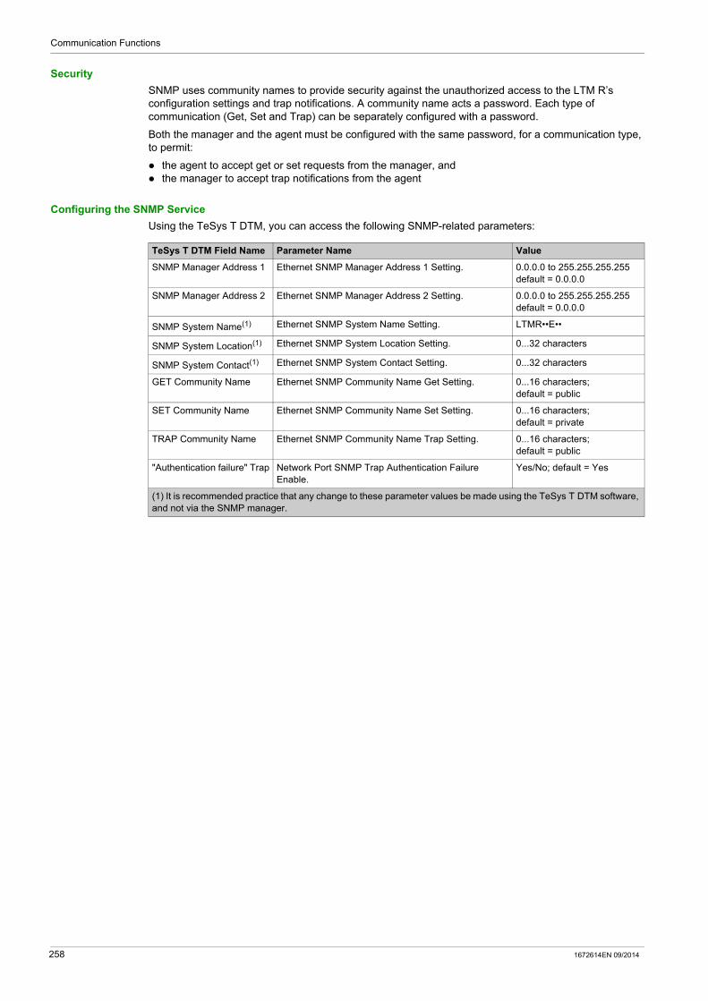
Communication Functions
Security
SNMP uses community names to provide security against the unauthorized access to the LTM R’s configuration settings and trap notifications. A community name acts a password. Each type of communication (Get, Set and Trap) can be separately configured with a password.
Both the manager and the agent must be configured with the same password, for a communication type, to permit:
the agent to accept get or set requests from the manager, and the manager to accept trap notifications from the agent
Configuring the SNMP Service
Using the TeSys T DTM, you can access the following SNMP-related parameters:
TeSys T DTM Field Name Parameter Name Value
SNMP Manager Address 1 Ethernet SNMP Manager Address 1 Setting. 0.0.0.0 to 255.255.255.255 default = 0.0.0.0
SNMP Manager Address 2 Ethernet SNMP Manager Address 2 Setting. 0.0.0.0 to 255.255.255.255 default = 0.0.0.0
SNMP System Name(1) Ethernet SNMP System Name Setting. LTMR••E••
SNMP System Location(1) Ethernet SNMP System Location Setting. 0...32 characters
SNMP System Contact(1) Ethernet SNMP System Contact Setting. 0...32 characters
GET Community Name Ethernet SNMP Community Name Get Setting. 0...16 characters; default = public
SET Community Name Ethernet SNMP Community Name Set Setting. 0...16 characters; default = private
TRAP Community Name Ethernet SNMP Community Name Trap Setting. 0...16 characters; default = public
"Authentication failure" Trap Network Port SNMP Trap Authentication Failure Enable.
Yes/No; default = Yes
(1) It is recommended practice that any change to these parameter values be made using the TeSys T DTM software, and not via the SNMP manager.
258 1672614EN 09/2014
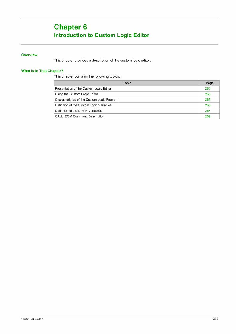
TeSys T DTM for FDT Container
Introduction to Custom Logic Editor
1672614EN 09/2014
Introduction to Custom Logic Editor
Chapter 6Introduction to Custom Logic Editor
Overview
This chapter provides a description of the custom logic editor.
What Is in This Chapter?
This chapter contains the following topics:
Topic Page
Presentation of the Custom Logic Editor 260
Using the Custom Logic Editor 263
Characteristics of the Custom Logic Program 265
Definition of the Custom Logic Variables 266
Definition of the LTM R Variables 267
CALL_EOM Command Description 269
1672614EN 09/2014 259
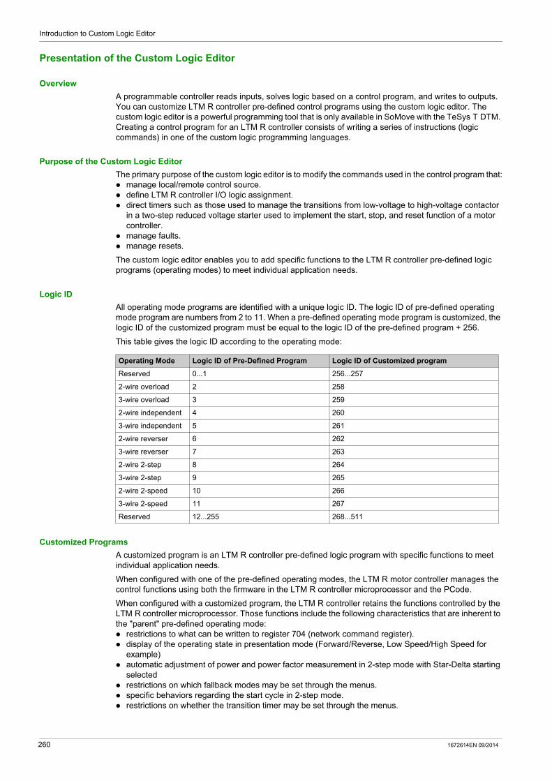
Introduction to Custom Logic Editor
Presentation of the Custom Logic Editor
Overview
A programmable controller reads inputs, solves logic based on a control program, and writes to outputs. You can customize LTM R controller pre-defined control programs using the custom logic editor. The custom logic editor is a powerful programming tool that is only available in SoMove with the TeSys T DTM. Creating a control program for an LTM R controller consists of writing a series of instructions (logic commands) in one of the custom logic programming languages.
Purpose of the Custom Logic Editor
The primary purpose of the custom logic editor is to modify the commands used in the control program that: manage local/remote control source. define LTM R controller I/O logic assignment. direct timers such as those used to manage the transitions from low-voltage to high-voltage contactor
in a two-step reduced voltage starter used to implement the start, stop, and reset function of a motor controller.
manage faults. manage resets.
The custom logic editor enables you to add specific functions to the LTM R controller pre-defined logic programs (operating modes) to meet individual application needs.
Logic ID
All operating mode programs are identified with a unique logic ID. The logic ID of pre-defined operating mode program are numbers from 2 to 11. When a pre-defined operating mode program is customized, the logic ID of the customized program must be equal to the logic ID of the pre-defined program + 256.
This table gives the logic ID according to the operating mode:
Customized Programs
A customized program is an LTM R controller pre-defined logic program with specific functions to meet individual application needs.
When configured with one of the pre-defined operating modes, the LTM R motor controller manages the control functions using both the firmware in the LTM R controller microprocessor and the PCode.
When configured with a customized program, the LTM R controller retains the functions controlled by the LTM R controller microprocessor. Those functions include the following characteristics that are inherent to the "parent" pre-defined operating mode: restrictions to what can be written to register 704 (network command register). display of the operating state in presentation mode (Forward/Reverse, Low Speed/High Speed for
example) automatic adjustment of power and power factor measurement in 2-step mode with Star-Delta starting
selected restrictions on which fallback modes may be set through the menus. specific behaviors regarding the start cycle in 2-step mode. restrictions on whether the transition timer may be set through the menus.
Operating Mode Logic ID of Pre-Defined Program Logic ID of Customized program
Reserved 0...1 256...257
2-wire overload 2 258
3-wire overload 3 259
2-wire independent 4 260
3-wire independent 5 261
2-wire reverser 6 262
3-wire reverser 7 263
2-wire 2-step 8 264
3-wire 2-step 9 265
2-wire 2-speed 10 266
3-wire 2-speed 11 267
Reserved 12...255 268...511
260 1672614EN 09/2014
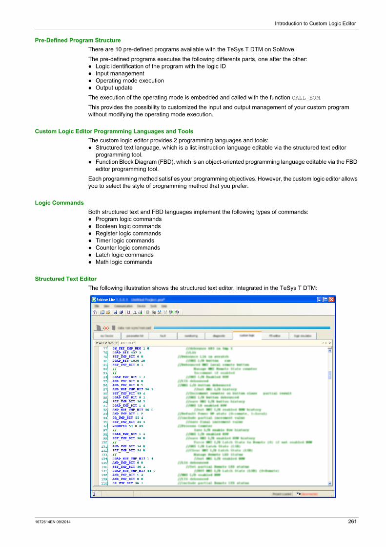
Introduction to Custom Logic Editor
Pre-Defined Program Structure
There are 10 pre-defined programs available with the TeSys T DTM on SoMove.
The pre-defined programs executes the following differents parts, one after the other: Logic identification of the program with the logic ID Input management Operating mode execution Output update
The execution of the operating mode is embedded and called with the function CALL_EOM.
This provides the possibility to customized the input and output management of your custom program without modifying the operating mode execution.
Custom Logic Editor Programming Languages and Tools
The custom logic editor provides 2 programming languages and tools: Structured text language, which is a list instruction language editable via the structured text editor
programming tool. Function Block Diagram (FBD), which is an object-oriented programming language editable via the FBD
editor programming tool.
Each programming method satisfies your programming objectives. However, the custom logic editor allows you to select the style of programming method that you prefer.
Logic Commands
Both structured text and FBD languages implement the following types of commands: Program logic commands Boolean logic commands Register logic commands Timer logic commands Counter logic commands Latch logic commands Math logic commands
Structured Text Editor
The following illustration shows the structured text editor, integrated in the TeSys T DTM:
1672614EN 09/2014 261

Introduction to Custom Logic Editor
FBD Editor
The following illustration shows the FBD editor, integrated in TeSys T DTM:
262 1672614EN 09/2014

Introduction to Custom Logic Editor
Using the Custom Logic Editor
Overview
The custom logic editor enables you to create and validate your own custom logic program to match with your needs. Once it is made, the LTM R controller firmware loads and executes instructions you created.
Task Flow Diagram
The following diagram shows all of the tasks to be carried out during the creation and modification of a custom logic program.
Note: The order defined is provided as an example. The order you use will depend on your own work methods.
1672614EN 09/2014 263

Introduction to Custom Logic Editor
Customization Method in Structured Text
Customization Method in FBD
Step Action
1 Define the operating modes that matches your application needs.
2 Open the pre-defined operating mode program file (*.rtf) in the custom logic editor.
3 Edit the pre-defined program in structured text, customize the program following one of the 3 methods: the pre-defined operating mode matches your application needs: use only
the CALL_EOM function. the pre-defined operating mode matches your application needs but
additional functions are required: use the CALL_EOM function and add the additional instructions after the CALL_EOM instructions.
the pre-defined operating mode does not match your application needs: start a new program from scratch (not recommended).
4 If required, edit the inputs of the customized program.
5 If required, edit the outputs of the customized program.
6 Update the Logic ID (see page 260) according to the CALL_EOM and the control mode.
7 Simulate the customized program.
8 Compile the customized program.
Step Action
1 Open a blank FBD program page.
2 Create the inputs management of the customized program.
3 Create the operating mode execution following one of the 3 methods: one of the operating mode matches your application needs: use only the
CALL_EOM function one of the operating mode matches your application needs but additional
functions are required: use the CALL_EOM function and add the additional instructions after the CALL_EOM instructions.
none of the operating mode matches your application needs: create a new program from scratch (not recommended).
4 Create the output management of the customized program.
5 Update the Logic ID (see page 260) according to the CALL_EOM and the control mode.
6 Simulate the customized program.
7 Compile the customized program.
264 1672614EN 09/2014

Introduction to Custom Logic Editor
Characteristics of the Custom Logic Program
Introduction
The data transferred to or from the LTM R controller is in the form of 16-bit registers. The registers are numerically ordered and referenced by a 16-bit register address (0...65,535).
The custom logic program can modify the values of 3 types of registers: LTM R controller variables Temporary registers Non-volatile registers
Logic Memory Characteristics
The list of commands for the control program is saved in an area of the internal non-volatile memory of the LTM R controller.
The format of this logic memory is illustrated in this table:
Logic Memory Limits
The program size is dependent on the number of logic commands. While in the text editor a command and its arguments will occupy a single line, in the memory, it will occupy as many memory locations as there are arguments.
As an example, the command timer 0.1 980 will use 4 memory locations.
Memory location
Item Range Description
0 Logic Program Size (n) 0...8,1910 means that no customized program is loaded.
16-bit word
1 Logic Checksum 0...65,535 Sum of program memory from offset 2...n+2
2 Logic ID 0...511 (see page 260) Identifier of the custom logic program within the LTM R controller
3 Logic Command/Argument 1Depending on the logic command type (see page 289)
One word of logic function
4 Logic Command/Argument 2
5 Logic Command/Argument 3
... ... ... ...
n+2 Logic Command/Argument n – One word of logic function
1672614EN 09/2014 265
Introduction to Custom Logic Editor
Definition of the Custom Logic Variables
Introduction
The custom logic editor enables you to implement commands in the control program which direct the LTM R controller to read or write to the temporary or non-volatile or LTM R variables.
The LTM R controller defines each custom logic register by an integer describing its address in custom logic memory space. The value of this integer begins at address 0 and the maximum address is equal to 1 less than the number of memory locations available for temporary registers in the LTM R controller. The LTM R controller lists the number of temporary registers available as a value in the LTM R control register 1204, which is the parameter for Custom Logic Temporary Space.
Temporary Registers
The controller provides registers in temporary memory that can be accessed by logic commands. Because these registers exist in temporary or volatile memory, they do not retain their value settings when power to the controller is cycled.
Variables can be stored in temporary registers from 0 to 299. Thus, 300 temporary registers are available.
Non-Volatile Registers
The LTM R controller provides registers in non-volatile memory for use by logic commands. Because these registers exist in non-volatile memory, they retain their value settings when power to the controller is cycled.
Variables can be stored in non-volatile registers from 0 to 63. Thus, 64 non-volatile registers are available.
266 1672614EN 09/2014
Introduction to Custom Logic Editor
Definition of the LTM R Variables
Overview
Custom logic commands can be used to change the values of read-write data registers of the LTM R controller.
LTM R Variables
Controller memory includes data registers at addresses ranging from 0 to 1399.
Each register is a 16-bit word and is either: read-only, with values that cannot be edited. read-write, with values that can be edited.
Accessing Variables
Using the custom logic editor, you can access all LTM R controller variables defined in the sections on Communication Variables in the Use chapter of the TeSys T LTM R Motor Management Controller User Manuals.
Custom Logic Register
Registers 1200...1205 are used by the TeSys T DTM to access internal register data within the LTM R controller. These registers are also the custom logic registers accessible from the communication ports. These read-only registers are described in the following sections.
This table lists these registers:
Register 1200
Register 1200 is the custom logic status register. It enables the customized program to configure I/O assignment.
This table describes each bit in this register:
Register Definition Range (value)
1200 Custom logic status register
0...65,535
1201 Custom logic version
1202 Custom logic memory space
1203 Custom logic memory used
1204 Custom logic temporary space
1205 Custom logic non-volatile space
Bit number Description
0 Custom logic run
1 Custom logic stop
2 Custom logic reset
3 Custom logic second step
4 Custom logic transition
5 Custom logic phase reverse
6 Custom logic network control
7 Custom logic FLC selection
8 (Reserved)
9 Custom logic auxiliary 1 LED of the LTM CU Control Operator Unit
10 Custom logic auxiliary 2 LED of the LTM CU Control Operator Unit
11 Custom logic stop LED of the LTM CU Control Operator Unit (not used)
12 Custom logic LO1
13 Custom logic LO2
14 Custom logic LO3
15 Custom logic LO4
1672614EN 09/2014 267
Introduction to Custom Logic Editor
Register 1201
Register 1201 indicates the custom logic capability version. The version number identifies a specific group of logic commands supported by the LTM R controller.
Register 1202
Register 1202 defines the logic memory space available, that is, the number of non-volatile LTM R controller logic memory words (16 bits) available to save logic commands.
Register 1203
Register 1203 defines the logic memory used, that is, the number of non-volatile LTM R logic memory words (16 bits) used by logic commands which are currently stored in the LTM R controller.
Register 1204
Register 1204 defines the number of temporary registers provided by the LTM R controller.
Register 1205
Register 1205 defines the number of non-volatile registers provided by the LTM R controller.
Registers 1301...1399
Registers 1301...1399 are the General Purpose Registers for logic functions. They are used to exchange information between external sources (such as the PLC) and the custom logic applications.
These volatile registers are read/write and can be edited either by the custom logic functions or via the communication port.
268 1672614EN 09/2014

Introduction to Custom Logic Editor
CALL_EOM Command Description
Overview
The CALL_EOM function allows to execute an operating mode.
For this purpose, the function uses the temporary registers 0 to 61.
To build a customized program around the CALL_EOM function, it is necessaire to understand how the different registers of the application and the LTM R are used:
Register 16 to 18 are the input registers of the CALL_EOM function, when customized, they must be assigned bit per bit.
Register 15 is the output register of the CALL_EOM function, its value is given after the execution of the operating mode.
Register 19 is a temporary register used to set the register 1200 in one time. The customization of the CALL_EOM outputs must be done using the register 19.
Register 20 bit 0 is the temporary bit used to set the terminal strip control (2-wire or 3-wire).
1672614EN 09/2014 269
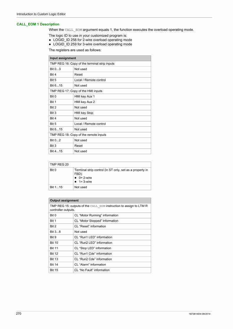
Introduction to Custom Logic Editor
CALL_EOM 1 Description
When the CALL_EOM argument equals 1, the function executes the overload operating mode.
The logic ID to use in your customized program is: LOGID_ID 258 for 2-wire overload operating mode LOGID_ID 259 for 3-wire overload operating mode
The registers are used as follows:
Input assignment
TMP REG 16: Copy of the terminal strip inputs
Bit 0...3 Not used
Bit 4 Reset
Bit 5 Local / Remote control
Bit 6...15 Not used
TMP REG 17: Copy of the HMI inputs
Bit 0 HMI key Aux 1
Bit 1 HMI key Aux 2
Bit 2 Not used
Bit 3 HMI key Stop
Bit 4 Not used
Bit 5 Local / Remote control
Bit 6...15 Not used
TMP REG 18: Copy of the remote inputs
Bit 0...2 Not used
Bit 3 Reset
Bit 4...15 Not used
TMP REG 20
Bit 0 Terminal strip control (in ST only, set as a property in FBD): 0= 2-wire 1= 3-wire
Bit 1...15 Not used
Output assignment
TMP REG 15: outputs of the CALL_EOM instruction to assign to LTM R controller outputs.
Bit 0 CL “Motor Running” information
Bit 1 CL “Motor Stopped” information
Bit 2 CL “Reset” information
Bit 3...8 Not used
Bit 9 CL “Run1 LED” information
Bit 10 CL “Run2 LED” information
Bit 11 CL “Stop LED” information
Bit 12 CL “Run1 Cde” information
Bit 13 CL “Run2 Cde” information
Bit 14 CL “Alarm” information
Bit 15 CL “No Fault” information
270 1672614EN 09/2014

Introduction to Custom Logic Editor
CALL_EOM 2 Description
When the CALL_EOM argument equals 2, the function executes the independent operating mode.
The logic ID to use in your customized program is: LOGID_ID 260 for 2-wire independent operating mode LOGID_ID 261 for 3-wire independent operating mode
The registers are used as follows:
Input assignment
TMP REG 16: Copy of the terminal strip inputs
Bit 0 Run1
Bit 1 Run2
Bit 2...3 Not used
Bit 4 Reset
Bit 5 Local / Remote control
Bit 6...15 Not used
TMP REG 17: Copy of the HMI inputs
Bit 0 HMI key Aux 1
Bit 1 HMI key Aux 2
Bit 2 Not used
Bit 3 HMI key Stop
Bit 5 Local / Remote control
Bit 6...15 Not used
TMP REG 18: Copy of the remote inputs
Bit 0 Run1
Bit 1 Run2
Bit 2 Not used
Bit 3 Reset
Bit 4...15 Not used
TMP REG 20
Bit 0 Terminal strip control (in ST only, set as a property in FBD): 0= 2-wire 1= 3-wire
Bit 1...15 Not used
Output assignment
TMP REG 15: outputs of the CALL_EOM instruction to assign to LTM R controller outputs.
Bit 0 CL “Motor Running” information
Bit 1 CL “Motor Stopped” information
Bit 2 CL “Reset” information
Bit 3...8 Not used
Bit 9 CL “Run1 LED” information
Bit 10 CL “Run2 LED” information
Bit 11 CL “Stop LED” information
Bit 12 CL “Run1 Cde” information
Bit 13 CL “Run2 Cde” information
Bit 14 CL “Alarm” information
Bit 15 CL “No Fault” information
1672614EN 09/2014 271

Introduction to Custom Logic Editor
CALL_EOM 3 Description
When the CALL_EOM argument equals 3, the function executes the reverser operating mode.
The logic ID to use in your customized program is: LOGID_ID 262 for 2-wire reverser operating mode LOGID_ID 263 for 3-wire reverser operating mode
The registers are used as follows:
Input assignment
TMP REG 16: Copy of the terminal strip inputs
Bit 0 Forward
Bit 1 Reverse
Bit 2...3 Not used
Bit 4 Reset
Bit 5 Local / Remote control
Bit 6...15 Not used
TMP REG 17: Copy of the HMI inputs
Bit 0 HMI key Aux 1
Bit 1 HMI key Aux 2
Bit 2 Not used
Bit 3 HMI key Stop
Bit 4 Not used
Bit 5 Local / Remote control
Bit 6...15 Not used
TMP REG 18: Copy of the remote inputs
Bit 0 Forward
Bit 1 Reverse
Bit 2 Not used
Bit 3 Reset
Bit 4...15 Not used
TMP REG 20
Bit 0 Terminal strip control (in ST only, set as a property in FBD): 0= 2-wire 1= 3-wire
Bit 1...15 Not used
Output assignment
TMP REG 15: outputs of the CALL_EOM instruction to assign to LTM R controller outputs.
Bit 0 CL “Motor Running” information
Bit 1 CL “Motor Stopped” information
Bit 2 CL “Reset” information
Bit 3...8 Not used
Bit 9 CL “Run1 LED” information
Bit 10 CL “Run2 LED” information
Bit 11 CL “Stop LED” information
Bit 12 CL “Run1 Cde” information
Bit 13 CL “Run2 Cde” information
Bit 14 CL “Alarm” information
Bit 15 CL “No Fault” information
272 1672614EN 09/2014

Introduction to Custom Logic Editor
CALL_EOM 4 Description
When the CALL_EOM argument equals 4, the function executes the 2-step operating mode.
The logic ID to use in your customized program is: LOGID_ID 264 for 2-wire 2-step operating mode LOGID_ID 265 for 3-wire 2-step operating mode
The registers are used as follows:
Input assignment
TMP REG 16: Copy of the terminal strip inputs
Bit 0 Run1
Bit 1...3 Not used
Bit 4 Reset
Bit 5 Local / Remote control
Bit 6...15 Not used
TMP REG 17: Copy of the HMI inputs
Bit 0 HMI key Aux 1
Bit 1...2 Not used
Bit 3 HMI key Stop
Bit 4 Not used
Bit 5 Local / Remote control
Bit 6...15 Not used
TMP REG 18: Copy of the remote inputs
Bit 0 Run1
Bit 1 Run2
Bit 2 Not used
Bit 3 Reset
Bit 4...15 Not used
TMP REG 20
Bit 0 Terminal strip control (in ST only, set as a property in FBD): 0= 2-wire 1= 3-wire
Bit 1...15 Not used
Output assignment
TMP REG 15: outputs of the CALL_EOM instruction to assign to LTM R controller outputs.
Bit 0 CL “Motor Running” information
Bit 1 CL “Motor Stopped” information
Bit 2 CL “Reset” information
Bit 3...8 Not used
Bit 9 CL “Run1 LED” information
Bit 10 CL “Run2 LED” information
Bit 11 CL “Stop LED” information
Bit 12 CL “Run1 Cde” information
Bit 13 CL “Run2 Cde” information
Bit 14 CL “Alarm” information
Bit 15 CL “No Fault” information
1672614EN 09/2014 273
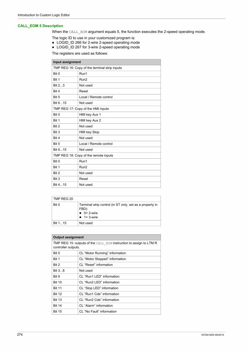
Introduction to Custom Logic Editor
CALL_EOM 5 Description
When the CALL_EOM argument equals 5, the function executes the 2-speed operating mode.
The logic ID to use in your customized program is: LOGID_ID 266 for 2-wire 2-speed operating mode LOGID_ID 267 for 3-wire 2-speed operating mode
The registers are used as follows:
Input assignment
TMP REG 16: Copy of the terminal strip inputs
Bit 0 Run1
Bit 1 Run2
Bit 2...3 Not used
Bit 4 Reset
Bit 5 Local / Remote control
Bit 6...15 Not used
TMP REG 17: Copy of the HMI inputs
Bit 0 HMI key Aux 1
Bit 1 HMI key Aux 2
Bit 2 Not used
Bit 3 HMI key Stop
Bit 4 Not used
Bit 5 Local / Remote control
Bit 6...15 Not used
TMP REG 18: Copy of the remote inputs
Bit 0 Run1
Bit 1 Run2
Bit 2 Not used
Bit 3 Reset
Bit 4...15 Not used
TMP REG 20
Bit 0 Terminal strip control (in ST only, set as a property in FBD): 0= 2-wire 1= 3-wire
Bit 1...15 Not used
Output assignment
TMP REG 15: outputs of the CALL_EOM instruction to assign to LTM R controller outputs.
Bit 0 CL “Motor Running” information
Bit 1 CL “Motor Stopped” information
Bit 2 CL “Reset” information
Bit 3...8 Not used
Bit 9 CL “Run1 LED” information
Bit 10 CL “Run2 LED” information
Bit 11 CL “Stop LED” information
Bit 12 CL “Run1 Cde” information
Bit 13 CL “Run2 Cde” information
Bit 14 CL “Alarm” information
Bit 15 CL “No Fault” information
274 1672614EN 09/2014
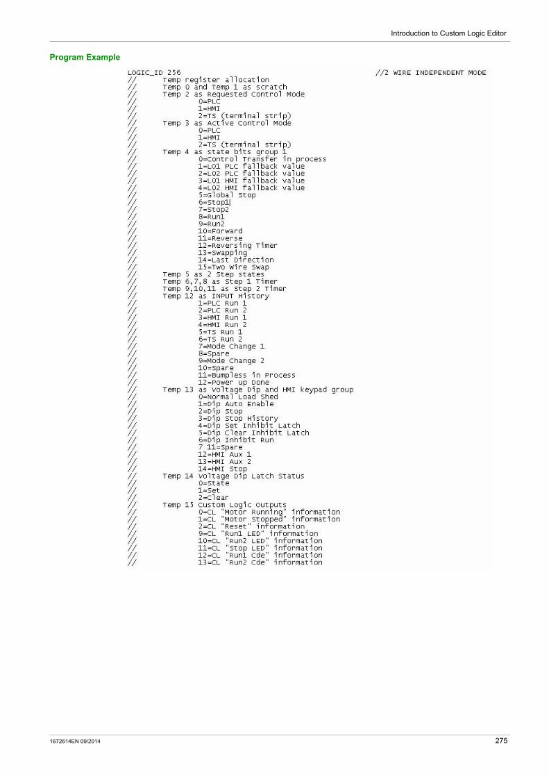
Introduction to Custom Logic Editor
Program Example
1672614EN 09/2014 275
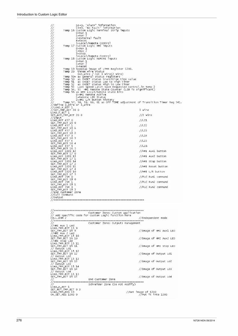
Introduction to Custom Logic Editor
276 1672614EN 09/2014
TeSys T DTM for FDT Container
Structured Text Language
1672614EN 09/2014
Structured Text Language
Chapter 7Structured Text Language
Overview
The structured text editor enables you to create a custom logic program based on the structured text programming language.
What Is in This Chapter?
This chapter contains the following sections:
Section Topic Page
7.1 Creating a Structured Text Program 278
7.2 Logic Commands 289
7.3 Structured Text Program Examples 316
1672614EN 09/2014 277
Structured Text Language
Creating a Structured Text Program
Section 7.1Creating a Structured Text Program
Summary
This section describes the creation of a program with the structured text editor.
Use the structured text editor to modify the pre-defined operating program by: changing the input and output assignments of the logic functions adding new logic functions that will change the step by step instructions of the original program
Create a new program by designing the step instructions customized to the specific requirements of the application.
What Is in This Section?
This section contains the following topics:
Topic Page
Introducing the Structured Text Editor 279
Structured Text Editor User Interface 280
Logic Commands 283
278 1672614EN 09/2014

Structured Text Language
Introducing the Structured Text Editor
Overview
The structured text editor is a feature of SoMove with the TeSys T DTM. Use the structured text editor to view an existing logic file or to create a logic file using an instruction based text language, rather than a graphics based programming language.
Editing a Structured Text Program
The easiest way to create a logic file is to begin with a logic file for one of the pre-defined operating modes (see page 264). Your installation of the custom logic editor comes with 10 pre-defined logic files, one for each combination of: operating mode (2-speed, 2-step, independent, overload, reverser), and control wiring selection (2-wire, 3-wire).
Each logic file bears a descriptive name (e.g. "3-wire-reverser") and a file extension of .lf.
Custom Logic Editor User Interface
To open the structured text editor, click Device →custom logic →New custom program.
The structured text editor is available regardless of whether the TeSys T DTM is in connected mode. However, the transfer of programs between the TeSys T DTM and the device works only in connected mode.
1672614EN 09/2014 279

Structured Text Language
Structured Text Editor User Interface
Introduction
A program written in list language consists of a series of instructions executed sequentially by the LTM R controller. Each list instruction is represented by a single program line and consists of 4 components: Line number Logic command (Mnemonics) Argument(s) Comment(s)
Example of a Structured Text Program
The following illustration is an example of a program created with the structured text editor.
Editing Several Programs
You can create or modify several custom logic programs at the same time. Click on the file name to switch between them.
For instance, in the Text view above, click either 2-wire-2-Step.rtf or Untitled3.lf depending on the program you wish to edit.
280 1672614EN 09/2014

Structured Text Language
Instruction Elements
The following illustration is a sample of structured text program:
Line Number
The line number is an additional information: It is defined only by the editor. It does not have any importance in the custom logic function itself.
Logic Command
A logic command is an instruction which identifies the operation to be performed using one or more arguments. In the example, the LOAD_BIT command loads the value of the argument into an internal register called the 1-bit accumulator.
There are 2 types of commands: Setup commands
These set-up or test for the necessary conditions to perform an action (for example, LOAD and AND commands).
Actions commandsThese commands direct the LTM R controller to perform an action based on info in the setup instructions (for example, assignment commands such as COMP).
NOTE: When you type a logic command, either uppercase or lowercase, it is automatically recognized and displayed in blue.
Argument
An argument is a number representing a value (register address, bit number, or constant) that the LTM R controller can manipulate in an instruction. For example, in the sample program, the second instruction LOAD_BIT 683 8 includes a logic command LOAD_BIT and 2 arguments, 683 and 8. This instructs the LTM R controller to load the value of register 683 bit 8 into the accumulator. A logic command can have from 0 to 3 arguments depending on the type of logic command.
Using instructions with commands and arguments, the LTM R controller program can: Read the status of controller inputs. Read or write the status of controller outputs. Activate basic logic functions such as timers and counters. Perform arithmetic, logical, comparisons, and numerical operations. Read or write to the LTM R controller’s internal registers or to individual bits in those registers.
NOTE: When you type an argument, it is automatically recognized and displayed in the color assigned to the arguments.
Comments
In the structured text editor, it is possible to add comments to the program: at the end of each line after the arguments in a whole line
NOTE:
When you type //, the custom logic editor automatically recognizes the text after it as comments and displays it in green.
Comments can not be retrieved from the LTM R controller.
1672614EN 09/2014 281

Structured Text Language
Syntax
In the structured text editor, it is possible to write instructions: with blanks, commas or dots between arguments in upper or lower characters
Syntax Check
During typing, the text editor checks the instruction syntax: Correct instructions are displayed in bold blue characters. Incorrect instructions stay displayed in black and must be corrected before the compilation.
Keyboard Commands
Keyboard commands and shortcuts are the same as those for Windows operating systems: press DEL or DELETE to delete a character or line, press ENTER to go to the next line, etc.
Saving
To save the program you edited or created, click Device → custom logic then select Save custom program or Save custom program as.
NOTE: This file is saved with the extension *.If.
282 1672614EN 09/2014

Structured Text Language
Logic Commands
Overview
All controller project files consist of a series of logic commands. Each logic command consists of the command itself, plus up to 3 arguments.
Each logic command performs its operation linked to either a 1-bit Boolean accumulator (value 0 or 1) or a 16-bit unsigned accumulator (value range 0...65,535).
The custom logic editor provides the following kinds of logic commands: Boolean Register Timers Latch Counters Math
Rising Edge Detection Mechanism
Some logic commands work on a rising edge of the 1-bit accumulator.
The rising edge of a bit is detected when its current state is 1 and its previous state was 0. The previous state of the bit is stored in a dedicated history bit.
NOTE: If this history bit is modified, the detection of the rising edge can be disturbed.
Boolean Logic Commands
Boolean commands evaluate and control simple Boolean (On/Off) values. Boolean commands include:
Command Argument 1 Argument 2 Argument 3 Description
LOAD_K_BIT Constant value (0 or 1)
– – Loads a constant value into the 1-bit accumulator.
LOAD_BIT Register address
Register bit no. (0...15)
– Loads a register bit from the address identified in Argument 1, and the bit identified in Argument 2 into the 1-bit accumulator.
LOAD_TMP_BIT Temporary register address
Register bit no. (0...15)
– Loads a temporary register bit into the 1-bit accumulator.
LOAD_NV_BIT Non-volatile register address
Register bit no. (0...15)
– Loads a non-volatile register bit into the 1-bit accumulator.
LOAD_NOT_BIT Register address
Register bit no. (0...15)
– Loads an inverted Boolean value of a register bit into the 1-bit accumulator.
LOAD_NOT_TMP_BIT Temporary register address
Register bit no. (0...15)
– Loads an inverted Boolean value of a temporary register bit into the 1-bit accumulator.
LOAD_NOT_NV_BIT Non-volatile register address
Register bit no. (0...15)
– Loads an inverted Boolean value of a non-volatile register bit into the 1-bit accumulator.
AND_BIT Register address
Register bit no. (0...15)
– Loads the result of a logical AND link between the register bit value and the 1-bit accumulator content. The result is stored in the 1-bit accumulator.
AND_TMP_BIT Temporary register address
Register bit no. (0...15)
– Loads the result of a logical AND link between the temporary register bit value and the 1-bit accumulator content. The result is stored in the 1-bit accumulator.
AND_NV_BIT Non-volatile register address
Register bit no. (0...15)
– Loads the result of a logical AND link between the non-volatile register bit value and the 1-bit accumulator content. The result is stored in the 1-bit accumulator.
AND_NOT_BIT Register address
Register bit no. (0...15)
– Loads the result of a logical AND of the inverted register bit and the 1-bit accumulator. The result is stored in the 1-bit accumulator.
– Argument not applicable to logic command.
1672614EN 09/2014 283

Structured Text Language
AND_NOT_TMP_BIT Temporary register address
Register bit no. (0...15)
– Loads the result of a logical AND of the inverted temporary register bit and the 1-bit accumulator. The result is stored in the 1-bit accumulator.
AND_NOT_NV_BIT Non-volatile register address
Register bit no. (0...15)
– Loads the result of a logical AND of the inverted non-volatile register bit and the 1-bit accumulator. The result is stored in the 1-bit accumulator.
OR_BIT Register address
Register bit no. (0...15)
– Makes a logical OR link between the register bit value and the 1-bit accumulator content. The result is stored in the 1-bit accumulator.
OR_TMP_BIT Temporary register address
Register bit no. (0...15)
– Makes a logical OR link between the temporary register bit value and the 1-bit accumulator content. The result is stored in the 1-bit accumulator.
OR_NV_BIT Non-volatile register address
Register bit no. (0...15)
– Makes a logical OR link between the non-volatile register bit value and the 1-bit accumulator content. The result is stored in the 1-bit accumulator.
OR_NOT_BIT Register address
Register bit no. (0...15)
– Makes an logical OR of the inverted register bit and the 1-bit accumulator. The result is stored in the 1-bit accumulator.
OR_NOT_TMP_BIT Temporary register address
Register bit no. (0...15)
– Makes an logical OR of the inverted temporary register bit and the 1-bit accumulator. The result is stored in the 1-bit accumulator.
OR_NOT_NV_BIT Non-volatile register address
Register bit no. (0...15)
– Makes an logical OR of the inverted non-volatile register bit and the 1-bit accumulator. The result is stored in the 1-bit accumulator.
SET_BIT Register address
Register bit no. (0...15)
– Sets value of the 1-bit accumulator into a register bit.
SET_TMP_BIT Temporary register address
Register bit no. (0...15)
– Sets value of the 1-bit accumulator into a temporary register bit.
SET_NV_BIT Non-volatile register address
Register bit no. (0...15)
– Sets value of the 1-bit accumulator into a non-volatile register bit.
SET_NOT_BIT Register address
Register bit no. (0...15)
– Sets inverted value of the 1-bit accumulator into a register bit.
SET_NOT_TMP_BIT Temporary register address
Register bit no. (0...15)
– Sets inverted value of the 1-bit accumulator into a temporary register bit.
SET_NOT_NV_BIT Non-volatile register address
Register bit no. (0...15)
– Sets inverted value of the 1-bit accumulator into a non-volatile register bit.
Command Argument 1 Argument 2 Argument 3 Description
– Argument not applicable to logic command.
284 1672614EN 09/2014

Structured Text Language
Register Logic Commands
Register commands evaluate and control 16-bit values. Register commands include:
Command Argument 1 Argument 2 Argument 3 Description
LOAD_K_REG Constant value (0...65,535)
– – Loads a constant value into the 16-bit accumulator.
LOAD_REG Register address
– – Loads a copy of a register into the 16-bit accumulator.
LOAD_TMP_REG Temporary register address
– – Loads a copy of a temporary register into the 16-bit accumulator.
LOAD_NV_REG Non-volatile register address
– – Loads a copy of a non-volatile register into the 16-bit accumulator.
COMP_K_REG Constant value (0...65,535)
Temporary register address
– Compares the content of the Argument 1 to the 16-bit accumulator content and sets status Argument 2 bits as follows:BIT 1 ON if 16-bit accumulator < content of the Argument 1BIT 2 ON if 16-bit accumulator = content of the Argument 1BIT 3 ON if 16-bit accumulator > content of the Argument 1
COMP_REG Register address
Temporary register address
– Compares the content of the register defined by Argument 1 to the 16-bit accumulator content and sets status Argument 2 bits as follows:BIT 1 ON if 16-bit accumulator < content of the register defined by Argument 1BIT 2 ON if 16-bit accumulator = content of the register defined by Argument 1BIT 3 ON if 16-bit accumulator > content of the register defined by Argument 1
COMP_TMP_REG Temporary register address
Temporary register address
– Compares the content of the register defined by Argument 1 to the 16-bit accumulator content and sets status Argument 2 bits as follows:BIT 1 ON if 16-bit accumulator < content of the register defined by Argument 1BIT 2 ON if 16-bit accumulator = content of the register defined by Argument 1BIT 3 ON if 16-bit accumulator > content of the register defined by Argument 1
COMP_NV_REG Non-volatile register address
Temporary register address
– Compares the content of the register defined by Argument 1 to the 16-bit accumulator content and sets status Argument 2 bits as follows:BIT 1 ON if 16-bit accumulator < content of the register defined by Argument 1BIT 2 ON if 16-bit accumulator = content of the register defined by Argument 1BIT 3 ON if 16-bit accumulator > content of the register defined by Argument 1
AND_K Constant value (0...65,535)
– – Makes a logical AND link between the constant value and the 16-bit accumulator content. The result is stored in the 16-bit accumulator.
AND_REG Register address
– – Makes a logical AND link between the register value and the 16-bit accumulator content. The result is stored in the 16-bit accumulator.
– Argument not applicable to logic command.
1672614EN 09/2014 285
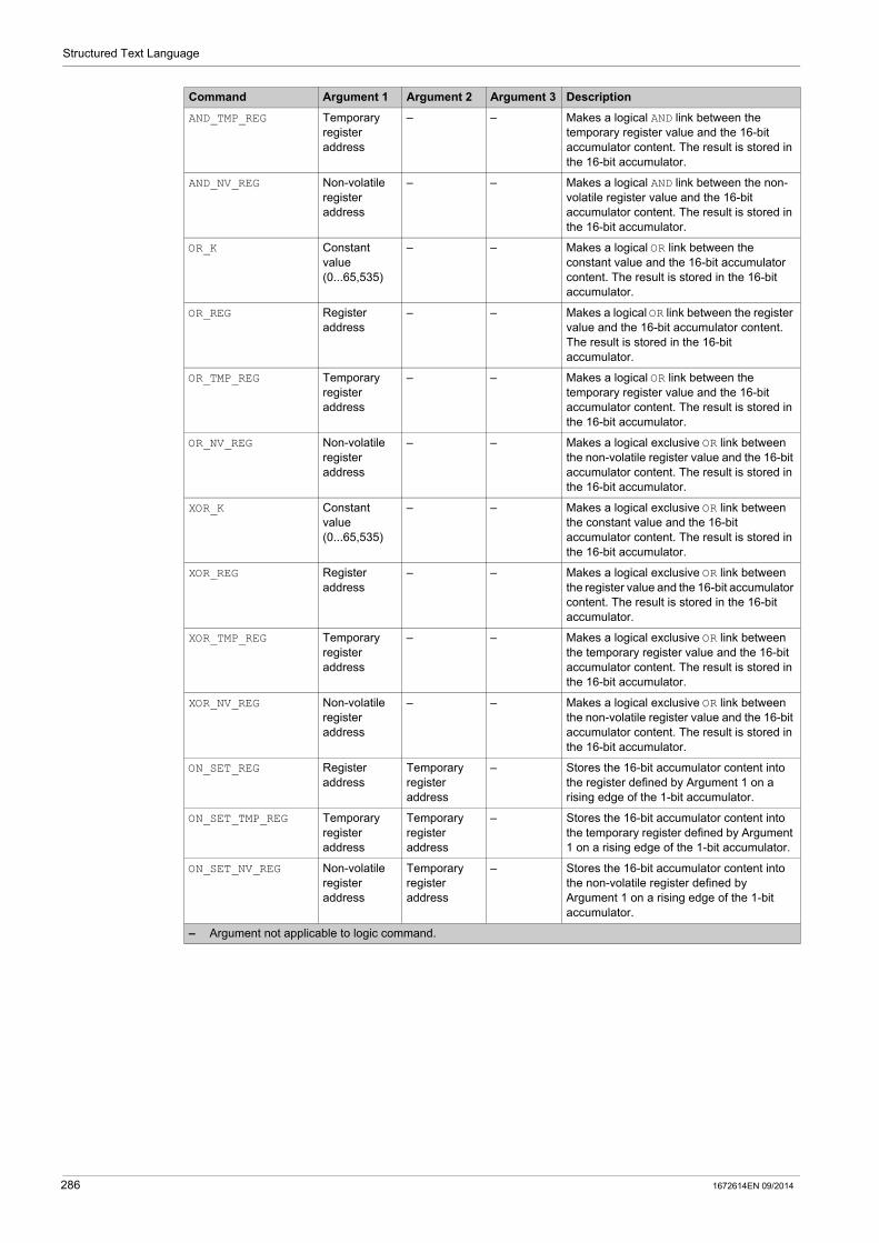
Structured Text Language
AND_TMP_REG Temporary register address
– – Makes a logical AND link between the temporary register value and the 16-bit accumulator content. The result is stored in the 16-bit accumulator.
AND_NV_REG Non-volatile register address
– – Makes a logical AND link between the non-volatile register value and the 16-bit accumulator content. The result is stored in the 16-bit accumulator.
OR_K Constant value (0...65,535)
– – Makes a logical OR link between the constant value and the 16-bit accumulator content. The result is stored in the 16-bit accumulator.
OR_REG Register address
– – Makes a logical OR link between the register value and the 16-bit accumulator content. The result is stored in the 16-bit accumulator.
OR_TMP_REG Temporary register address
– – Makes a logical OR link between the temporary register value and the 16-bit accumulator content. The result is stored in the 16-bit accumulator.
OR_NV_REG Non-volatile register address
– – Makes a logical exclusive OR link between the non-volatile register value and the 16-bit accumulator content. The result is stored in the 16-bit accumulator.
XOR_K Constant value (0...65,535)
– – Makes a logical exclusive OR link between the constant value and the 16-bit accumulator content. The result is stored in the 16-bit accumulator.
XOR_REG Register address
– – Makes a logical exclusive OR link between the register value and the 16-bit accumulator content. The result is stored in the 16-bit accumulator.
XOR_TMP_REG Temporary register address
– – Makes a logical exclusive OR link between the temporary register value and the 16-bit accumulator content. The result is stored in the 16-bit accumulator.
XOR_NV_REG Non-volatile register address
– – Makes a logical exclusive OR link between the non-volatile register value and the 16-bit accumulator content. The result is stored in the 16-bit accumulator.
ON_SET_REG Register address
Temporary register address
– Stores the 16-bit accumulator content into the register defined by Argument 1 on a rising edge of the 1-bit accumulator.
ON_SET_TMP_REG Temporary register address
Temporary register address
– Stores the 16-bit accumulator content into the temporary register defined by Argument 1 on a rising edge of the 1-bit accumulator.
ON_SET_NV_REG Non-volatile register address
Temporary register address
– Stores the 16-bit accumulator content into the non-volatile register defined by Argument 1 on a rising edge of the 1-bit accumulator.
Command Argument 1 Argument 2 Argument 3 Description
– Argument not applicable to logic command.
286 1672614EN 09/2014

Structured Text Language
Timer Logic Commands
Timers have a range from 0 to 65,535 and measure time in intervals of seconds or tenths of seconds: Argument 1 specifies the time period. Argument 2 is a calculated end time. Argument 3 is the timer status register.
Timer commands include:
Latch Logic Commands
Latch commands include:
Counter Logic Commands
Counters have a range from 0 to 65,535 and transition to 0 upon counting to the maximum value of 65,535.
Counter commands include:
Command Argument 1 Argument 2 Argument 3 Description
TIMER_SEC Temporary register (time period)
Temporary register (calculated end time)
Temporary register (status)
Counts in seconds the time period input in Argument 1 as described by status register bits.
TIMER_TENTHS Temporary register (time period)
Temporary register (calculated end time)
Temporary register (status)
Counts in tenths of seconds the time period input in Argument 1 as described by status register bits.
TIMER_K_SEC Constant value 0...65,535 (time period)
Temporary register (calculated end time)
Temporary register (status)
Counts in seconds the time period input in Argument 1 as described by status register bits.
TIMER_K_TENTHS Constant value 0...65,535 (time period)
Temporary register (calculated end time)
Temporary register (status)
Counts in tenths of seconds the time period input in Argument 1 as described by status register bits.
Command Argument 1 Argument 2 Argument 3 Description
LATCH Temporary register (status)
– – Records and retains in a temporary register a history of a signal.
LATCH_NV Non-volatile register (status)
– – Records and retains in a non-volatile register a history of a signal.
– Argument not applicable to logic command.
Command Argument 1 Argument 2 Argument 3 Description
COUNTER Temporary register (counter value)
Constant value 0...65,535 (preset value)
Temporary register (status)
Performs a comparative count, saving both the count and status to temporary registers.
COUNTER_NV Non-volatile register (counter value)
Constant value 0...65,535 (preset value)
Non-volatile register (status)
Performs a comparative count, saving both the count and status to non-volatile registers.
1672614EN 09/2014 287

Structured Text Language
Math Logic Commands
Math commands perform unsigned math functions using the 16-bit accumulator and temporary registers. Math commands are executed on a rising edge of the 1-bit accumulator. Math commands include:
Command Argument 1 Argument 2 Argument 3 Description
ON_ADD Temporary register (value)
Temporary register (status)
– Argument 1 = Argument 1 + 16-bit accumulator.
ON_SUB Temporary register (value)
Temporary register (status)
– Argument 1 = Argument 1 - 16-bit accumulator.
ON_MUL Temporary register (most significant word)
Temporary register (least significant word)
Temporary register (status)
Argument 1:Argument 2 = 16-bit accumulator x Argument 2.
ON_DIV Temporary register (most significant word)
Temporary register (least significant word)
Temporary register (status)
Argument 1:Argument 2 = Argument 1:Argument 2 / 16-bit accumulator.
– Argument not applicable to logic command.
288 1672614EN 09/2014
Structured Text Language
Logic Commands
Section 7.2Logic Commands
Summary
This section describes in detail the logic commands and arguments provided by the custom logic editor.
What Is in This Section?
This section contains the following topics:
Topic Page
Program Logic Commands 290
Boolean Logic Commands 291
Register Logic Commands 300
Timer Logic Commands 308
Latch Logic Commands 311
Counter Logic Commands 312
Math Logic Commands 314
1672614EN 09/2014 289
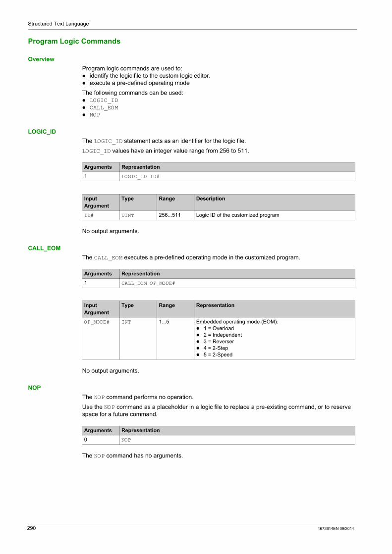
Structured Text Language
Program Logic Commands
Overview
Program logic commands are used to: identify the logic file to the custom logic editor. execute a pre-defined operating mode
The following commands can be used: LOGIC_ID CALL_EOM NOP
LOGIC_ID
The LOGIC_ID statement acts as an identifier for the logic file.
LOGIC_ID values have an integer value range from 256 to 511.
No output arguments.
CALL_EOM
The CALL_EOM executes a pre-defined operating mode in the customized program.
No output arguments.
NOP
The NOP command performs no operation.
Use the NOP command as a placeholder in a logic file to replace a pre-existing command, or to reserve space for a future command.
The NOP command has no arguments.
Arguments Representation
1 LOGIC_ID ID#
Input Argument
Type Range Description
ID# UINT 256...511 Logic ID of the customized program
Arguments Representation
1 CALL_EOM OP_MODE#
Input Argument
Type Range Representation
OP_MODE# INT 1...5 Embedded operating mode (EOM): 1 = Overload 2 = Independent 3 = Reverser 4 = 2-Step 5 = 2-Speed
Arguments Representation
0 NOP
290 1672614EN 09/2014
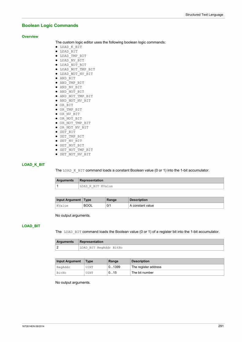
Structured Text Language
Boolean Logic Commands
Overview
The custom logic editor uses the following boolean logic commands: LOAD_K_BIT LOAD_BIT LOAD_TMP_BIT LOAD_NV_BIT LOAD_NOT_BIT LOAD_NOT_TMP_BIT LOAD_NOT_NV_BIT AND_BIT AND_TMP_BIT AND_NV_BIT AND_NOT_BIT AND_NOT_TMP_BIT AND_NOT_NV_BIT OR_BIT OR_TMP_BIT OR_NV_BIT OR_NOT_BIT OR_NOT_TMP_BIT OR_NOT_NV_BIT SET_BIT SET_TMP_BIT SET_NV_BIT SET_NOT_BIT SET_NOT_TMP_BIT SET_NOT_NV_BIT
LOAD_K_BIT
The LOAD_K_BIT command loads a constant Boolean value (0 or 1) into the 1-bit accumulator.
No output arguments.
LOAD_BIT
The LOAD_BIT command loads the Boolean value (0 or 1) of a register bit into the 1-bit accumulator.
No output arguments.
Arguments Representation
1 LOAD_K_BIT KValue
Input Argument Type Range Description
KValue BOOL 0/1 A constant value
Arguments Representation
2 LOAD_BIT RegAddr BitNo
Input Argument Type Range Description
RegAddr UINT 0...1399 The register address
BitNo UINT 0...15 The bit number
1672614EN 09/2014 291
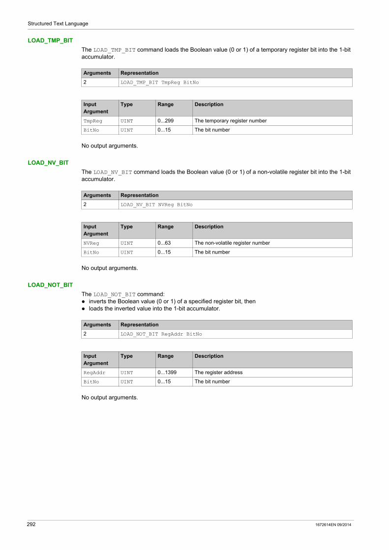
Structured Text Language
LOAD_TMP_BIT
The LOAD_TMP_BIT command loads the Boolean value (0 or 1) of a temporary register bit into the 1-bit accumulator.
No output arguments.
LOAD_NV_BIT
The LOAD_NV_BIT command loads the Boolean value (0 or 1) of a non-volatile register bit into the 1-bit accumulator.
No output arguments.
LOAD_NOT_BIT
The LOAD_NOT_BIT command: inverts the Boolean value (0 or 1) of a specified register bit, then loads the inverted value into the 1-bit accumulator.
No output arguments.
Arguments Representation
2 LOAD_TMP_BIT TmpReg BitNo
Input Argument
Type Range Description
TmpReg UINT 0...299 The temporary register number
BitNo UINT 0...15 The bit number
Arguments Representation
2 LOAD_NV_BIT NVReg BitNo
Input Argument
Type Range Description
NVReg UINT 0...63 The non-volatile register number
BitNo UINT 0...15 The bit number
Arguments Representation
2 LOAD_NOT_BIT RegAddr BitNo
Input Argument
Type Range Description
RegAddr UINT 0...1399 The register address
BitNo UINT 0...15 The bit number
292 1672614EN 09/2014

Structured Text Language
LOAD_NOT_TMP_BIT
The LOAD_NOT_TMP_BIT command: inverts the Boolean value (0 or 1) of a specified temporary register bit, then loads the inverted value into the 1-bit accumulator.
No output arguments.
LOAD_NOT_NV_BIT
The LOAD_NOT_NV_BIT command: inverts the Boolean value (0 or 1) of a selected non-volatile register bit, then loads the inverted value into the 1-bit accumulator.
No output arguments.
AND_BIT
The AND_BIT command makes a logical AND link between a register bit value and the accumulator content in logic memory: If the 1-bit accumulator equals 1 and the linked register bit equals 1, the result of the AND process is also
1. In all other cases the result of the AND process is 0.
The result is saved in the 1-bit accumulator.
No output arguments.
Arguments Representation
2 LOAD_NOT_TMP_BIT TmpReg BitNo
Input Argument
Type Range Description
TmpReg UINT 0...299 The temporary register number
BitNo UINT 0...15 The bit number
Arguments Representation
2 LOAD_NOT_NV_BIT NVReg BitNo
Input Argument
Type Range Description
NVReg UINT 0...63 The non-volatile register number
BitNo UINT 0...15 The bit number
Arguments Representation
2 AND_BIT RegAddr BitNo
Input Argument
Type Range Description
RegAddr UINT 0...1399 The register address
BitNo UINT 0...15 The bit number
1672614EN 09/2014 293
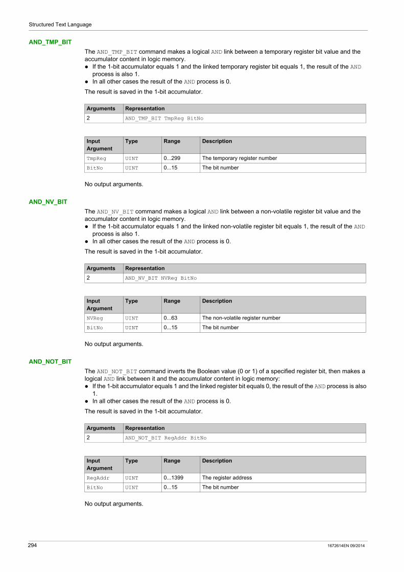
Structured Text Language
AND_TMP_BIT
The AND_TMP_BIT command makes a logical AND link between a temporary register bit value and the accumulator content in logic memory. If the 1-bit accumulator equals 1 and the linked temporary register bit equals 1, the result of the AND
process is also 1. In all other cases the result of the AND process is 0.
The result is saved in the 1-bit accumulator.
No output arguments.
AND_NV_BIT
The AND_NV_BIT command makes a logical AND link between a non-volatile register bit value and the accumulator content in logic memory. If the 1-bit accumulator equals 1 and the linked non-volatile register bit equals 1, the result of the AND
process is also 1. In all other cases the result of the AND process is 0.
The result is saved in the 1-bit accumulator.
No output arguments.
AND_NOT_BIT
The AND_NOT_BIT command inverts the Boolean value (0 or 1) of a specified register bit, then makes a logical AND link between it and the accumulator content in logic memory: If the 1-bit accumulator equals 1 and the linked register bit equals 0, the result of the AND process is also
1. In all other cases the result of the AND process is 0.
The result is saved in the 1-bit accumulator.
No output arguments.
Arguments Representation
2 AND_TMP_BIT TmpReg BitNo
Input Argument
Type Range Description
TmpReg UINT 0...299 The temporary register number
BitNo UINT 0...15 The bit number
Arguments Representation
2 AND_NV_BIT NVReg BitNo
Input Argument
Type Range Description
NVReg UINT 0...63 The non-volatile register number
BitNo UINT 0...15 The bit number
Arguments Representation
2 AND_NOT_BIT RegAddr BitNo
Input Argument
Type Range Description
RegAddr UINT 0...1399 The register address
BitNo UINT 0...15 The bit number
294 1672614EN 09/2014
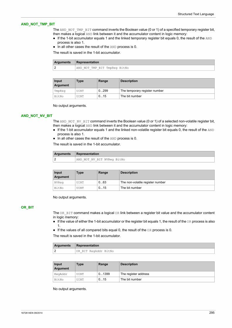
Structured Text Language
AND_NOT_TMP_BIT
The AND_NOT_TMP_BIT command inverts the Boolean value (0 or 1) of a specified temporary register bit, then makes a logical AND link between it and the accumulator content in logic memory: If the 1-bit accumulator equals 1 and the linked temporary register bit equals 0, the result of the AND
process is also 1. In all other cases the result of the AND process is 0.
The result is saved in the 1-bit accumulator.
No output arguments.
AND_NOT_NV_BIT
The AND_NOT_NV_BIT command inverts the Boolean value (0 or 1) of a selected non-volatile register bit, then makes a logical AND link between it and the accumulator content in logic memory: If the 1-bit accumulator equals 1 and the linked non-volatile register bit equals 0, the result of the AND
process is also 1. In all other cases the result of the AND process is 0.
The result is saved in the 1-bit accumulator.
No output arguments.
OR_BIT
The OR_BIT command makes a logical OR link between a register bit value and the accumulator content in logic memory: If the value of either the 1-bit accumulator or the register bit equals 1, the result of the OR process is also
1. If the values of all compared bits equal 0, the result of the OR process is 0.
The result is saved in the 1-bit accumulator.
No output arguments.
Arguments Representation
2 AND_NOT_TMP_BIT TmpReg BitNo
Input Argument
Type Range Description
TmpReg UINT 0...299 The temporary register number
BitNo UINT 0...15 The bit number
Arguments Representation
2 AND_NOT_NV_BIT NVReg BitNo
Input Argument
Type Range Description
NVReg UINT 0...63 The non-volatile register number
BitNo UINT 0...15 The bit number
Arguments Representation
2 OR_BIT RegAddr BitNo
Input Argument
Type Range Description
RegAddr UINT 0...1399 The register address
BitNo UINT 0...15 The bit number
1672614EN 09/2014 295
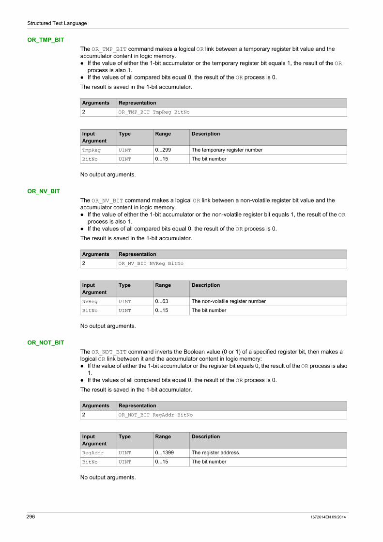
Structured Text Language
OR_TMP_BIT
The OR_TMP_BIT command makes a logical OR link between a temporary register bit value and the accumulator content in logic memory. If the value of either the 1-bit accumulator or the temporary register bit equals 1, the result of the OR
process is also 1. If the values of all compared bits equal 0, the result of the OR process is 0.
The result is saved in the 1-bit accumulator.
No output arguments.
OR_NV_BIT
The OR_NV_BIT command makes a logical OR link between a non-volatile register bit value and the accumulator content in logic memory. If the value of either the 1-bit accumulator or the non-volatile register bit equals 1, the result of the OR
process is also 1. If the values of all compared bits equal 0, the result of the OR process is 0.
The result is saved in the 1-bit accumulator.
No output arguments.
OR_NOT_BIT
The OR_NOT_BIT command inverts the Boolean value (0 or 1) of a specified register bit, then makes a logical OR link between it and the accumulator content in logic memory: If the value of either the 1-bit accumulator or the register bit equals 0, the result of the OR process is also
1. If the values of all compared bits equal 0, the result of the OR process is 0.
The result is saved in the 1-bit accumulator.
No output arguments.
Arguments Representation
2 OR_TMP_BIT TmpReg BitNo
Input Argument
Type Range Description
TmpReg UINT 0...299 The temporary register number
BitNo UINT 0...15 The bit number
Arguments Representation
2 OR_NV_BIT NVReg BitNo
Input Argument
Type Range Description
NVReg UINT 0...63 The non-volatile register number
BitNo UINT 0...15 The bit number
Arguments Representation
2 OR_NOT_BIT RegAddr BitNo
Input Argument
Type Range Description
RegAddr UINT 0...1399 The register address
BitNo UINT 0...15 The bit number
296 1672614EN 09/2014

Structured Text Language
OR_NOT_TMP_BIT
The OR_NOT_TMP_BIT command inverts the Boolean value (0 or 1) of a specified temporary register bit, then makes a logical OR link between it and the accumulator content in logic memory: If the value of either the 1-bit accumulator or the temporary register bit equals 0, the result of the OR
process is also 1. If the values of all compared bits equal 0, the result of the OR process is 0.
The result is saved in the 1-bit accumulator.
No output arguments.
OR_NOT_NV_BIT
The OR_NOT_NV_BIT command inverts the Boolean value (0 or 1) of a selected non-volatile register bit, then makes a logical OR link between it and the accumulator content in logic memory: If the value of either the 1-bit accumulator or the non-volatile register bit equals 0, the result of the OR
process is also 1. If the values of all compared bits equal 0, the result of the OR process is 0.
The result is saved in the 1-bit accumulator.
No output arguments.
SET_BIT
The SET_BIT command sets the value of the 1-bit accumulator to a specified register bit.
No input arguments.
Arguments Representation
2 OR_NOT_TMP_BIT TmpReg BitNo
Input Argument
Type Range Description
TmpReg UINT 0...299 The temporary register number
BitNo UINT 0...15 The bit number
Arguments Representation
2 OR_NOT_NV_BIT NVReg BitNo
Input Argument
Type Range Description
NVReg UINT 0...63 The non-volatile register number
BitNo UINT 0...15 The bit number
Arguments Representation
2 SET_BIT RegAddr BitNo
Output Argument
Type Range Description
RegAddr UINT 0...1399 The address of the specified register
BitNo UINT 0...15 The number of the bit to be set in the specified register
1672614EN 09/2014 297

Structured Text Language
SET_TMP_BIT
The SET_TMP_BIT command sets the value of the 1-bit accumulator to a specified temporary register bit.
No input arguments.
SET_NV_BIT
The SET_NV_BIT command sets the value of the 1-bit accumulator to a specified non-volatile register bit.
No input arguments.
SET_NOT_BIT
The SET_NOT_BIT command sets the inverted value of the 1-bit accumulator to a specified register bit.
No input arguments.
SET_NOT_TMP_BIT
The SET_NOT_TMP_BIT command sets the inverted value of the 1-bit accumulator to a specified temporary register bit.
No input arguments.
Arguments Representation
2 SET_TMP_BIT TmpReg BitNo
Output Argument
Type Range Description
TmpReg UINT 0...299 The address of the specified temporary register
BitNo UINT 0...15 The number of the bit to be set in the specified temporary register
Arguments Representation
2 SET_NV_BIT NVReg BitNo
Output Argument
Type Range Description
NVReg UINT 0...63 The address of the specified non-volatile register
BitNo UINT 0...15 The number of the bit to be set in the specified non-volatile register
Arguments Representation
2 SET_NOT_BIT RegAddr BitNo
Output Argument
Type Range Description
RegAddr UINT 0...1399 The address of the specified register
BitNo UINT 0...15 The number of the bit to be set in the specified register
Arguments Representation
2 SET_NOT_TMP_BIT TmpReg BitNo
Output Argument
Type Range Description
TmpReg UINT 0...299 The address of the specified temporary register
BitNo UINT 0...15 The number of the bit to be set in the specified temporary register
298 1672614EN 09/2014

Structured Text Language
SET_NOT_NV_BIT
The SET_NOT_NV_BIT command sets the inverted value of the 1-bit accumulator to a specified non-volatile register bit.
No input arguments.
Arguments Representation
2 SET_NOT_NV_BIT NVReg BitNo
Output Arguments
Type Range Description
NVReg UINT 0...63 The address of the specified non-volatile register
BitNo UINT 0...15 The number of the bit to be set in the specified non-volatile register
1672614EN 09/2014 299

Structured Text Language
Register Logic Commands
Overview
Register commands evaluate and control 16-bit values.
The custom logic editor uses the following register commands: LOAD_K_REG LOAD_REG LOAD_TMP_REG LOAD_NV_REG COMP_K_REG COMP_REG COMP_TMP_REG COMP_NV_REG AND_K AND_REG AND_TMP_REG AND_NV_REG OR_K OR_REG OR_TMP_REG OR_NV_REG XOR_K XOR_REG XOR_TMP_REG XOR_NV_REG ON_SET_REG ON_SET_TMP_REG ON_SET_NV_REG
LOAD_K_REG
The LOAD_K_REG command loads a 16-bit constant value into the 16-bit accumulator in logic memory.
No output arguments.
LOAD_REG
The LOAD_REG command loads a copy of a register into the 16-bit accumulator in logic memory.
No output arguments.
Arguments Representation
1 LOAD_K_REG KValue
Input Argument Type Range Description
KValue UINT 0...65,535 A constant value
Arguments Representation
1 LOAD_REG RegAddr
Input Argument Type Range Description
RegAddr UINT 0...1399 The register address
300 1672614EN 09/2014

Structured Text Language
LOAD_TMP_REG
The LOAD_TMP_REG command loads a copy of a temporary register into the 16-bit accumulator in logic memory.
No output arguments.
LOAD_NV_REG
The LOAD_NV_REG command loads a copy of a non-volatile register into the 16-bit accumulator in logic memory.
No output arguments.
COMP_K_REG
The COMP_K_REG command compares the 16-bit accumulator content to the Argument 1 constant value and sets the result of the comparison in one bit of the Argument 2 temporary register.
Arguments Representation
1 LOAD_TMP_REG TmpReg
Input Argument
Type Range Description
TmpReg UINT 0...299 The temporary register number
Arguments Representation
1 LOAD_NV_REG NVReg
Input Argument
Type Range Description
NVReg UINT 0...63 The non-volatile register number
Arguments Representation
2 COMP_K_REG KValue TmpReg
Input Argument
Type Range/Bit Description
KValue UINT 0...65,535 A constant value
Output Argument
Type Range/Bit Description
TmpReg UINT Bit1 16-bit accumulator < KValue
Bit2 16-bit accumulator = KValue
Bit3 16-bit accumulator > KValue
1672614EN 09/2014 301

Structured Text Language
COMP_REG
The COMP_REG command compares the 16-bit accumulator content to the content of the register defined by Argument 1 and sets the result of the comparison in one bit of the Argument 2 temporary register.
COMP_TMP_REG
The COMP_TMP_REG command compares the 16-bit accumulator content to the content of the temporary register defined by Argument 1 and sets the result of the comparison in one bit of the Argument 2 temporary register.
COMP_NV_REG
The COMP_NV_REG command compares the 16-bit accumulator content to the content of the non-volatile register defined by Argument 1 and sets the result of the comparison in one bit of the Argument 2 temporary register.
Arguments Representation
2 COMP_REG RegAddr TmpReg
Input Argument
Type Range/Bit Description
RegAddr UINT 0...1399 The register address
Output Argument
Type Range/Bit Description
TmpReg UINT Bit1 16-bit accumulator < RegAddr
Bit2 16-bit accumulator = RegAddr
Bit3 16-bit accumulator > RegAddr
Arguments Representation
2 COMP_TMP_REG TmpReg1 TmpReg2
Input Argument
Type Range/Bit Description
TmpReg1 UINT 0...299 Temporary register number
Output Argument
Type Range/Bit Description
TmpReg2 UINT Bit1 16-bit accumulator < TmpReg1
Bit2 16-bit accumulator = TmpReg1
Bit3 16-bit accumulator > TmpReg1
Arguments Representation
2 COMP_NV_REG NVReg TmpReg
Input Argument
Type Range/Bit Description
NVReg UINT 0...63 Non-volatile register number
Output Argument
Type Range/Bit Description
TmpReg UINT Bit1 16-bit accumulator < NVReg
Bit2 16-bit accumulator = NVReg
Bit3 16-bit accumulator > NVReg
302 1672614EN 09/2014

Structured Text Language
AND_K
The AND_K command makes a logical AND link between a 16-bit constant value and the 16-bit accumulator content in logic memory. The result is saved in the 16-bit accumulator.
The AND process compares each bit in the 16-bit accumulator with the corresponding bit in the linked 16-bit constant value: If both bits equal 1, the result of the AND process for that bit number is also 1. In all other cases the result of the AND process for that bit number is 0.
No output arguments.
AND_REG
The AND_REG command makes a logical AND link between the register value and the 16-bit accumulator content in logic memory. The result is saved in the 16-bit accumulator.
The AND process compares each bit in the 16-bit accumulator with the corresponding bit in the linked register: If both bits equal 1, the result of the AND process for that bit number is also 1. In all other cases the result of the AND process for that bit number is 0.
No output arguments.
AND_TMP_REG
The AND_TMP_REG command makes a logical AND link between the temporary register value and the 16-bit accumulator content in logic memory. The result is saved in the 16-bit accumulator.
The AND process compares each bit in the 16-bit accumulator with the corresponding bit in the linked temporary register: If both bits equal 1, the result of the AND process for that bit number is also 1. In all other cases the result of the AND process for that bit number is 0.
No output arguments.
Arguments Representation
1 AND_K KValue
Input Argument
Type Range Description
KValue UINT 0...65,535 A constant value
Arguments Representation
1 AND_REG RegAddr
Input Argument
Type Range Description
RegAddr UINT 0...1399 The register address
Arguments Representation
1 AND_TMP_REG TmpReg
Input Argument
Type Range Description
TmpReg UINT 0...299 The temporary register number
1672614EN 09/2014 303
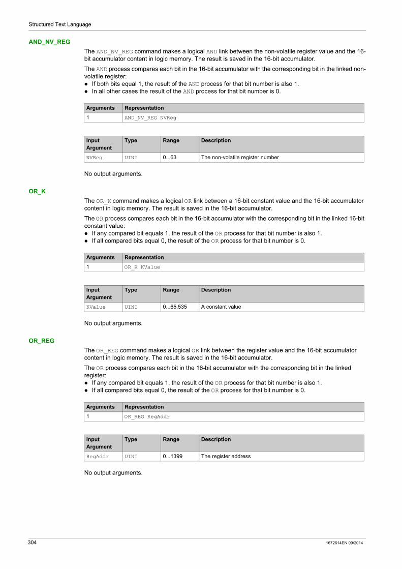
Structured Text Language
AND_NV_REG
The AND_NV_REG command makes a logical AND link between the non-volatile register value and the 16-bit accumulator content in logic memory. The result is saved in the 16-bit accumulator.
The AND process compares each bit in the 16-bit accumulator with the corresponding bit in the linked non-volatile register: If both bits equal 1, the result of the AND process for that bit number is also 1. In all other cases the result of the AND process for that bit number is 0.
No output arguments.
OR_K
The OR_K command makes a logical OR link between a 16-bit constant value and the 16-bit accumulator content in logic memory. The result is saved in the 16-bit accumulator.
The OR process compares each bit in the 16-bit accumulator with the corresponding bit in the linked 16-bit constant value: If any compared bit equals 1, the result of the OR process for that bit number is also 1. If all compared bits equal 0, the result of the OR process for that bit number is 0.
No output arguments.
OR_REG
The OR_REG command makes a logical OR link between the register value and the 16-bit accumulator content in logic memory. The result is saved in the 16-bit accumulator.
The OR process compares each bit in the 16-bit accumulator with the corresponding bit in the linked register: If any compared bit equals 1, the result of the OR process for that bit number is also 1. If all compared bits equal 0, the result of the OR process for that bit number is 0.
No output arguments.
Arguments Representation
1 AND_NV_REG NVReg
Input Argument
Type Range Description
NVReg UINT 0...63 The non-volatile register number
Arguments Representation
1 OR_K KValue
Input Argument
Type Range Description
KValue UINT 0...65,535 A constant value
Arguments Representation
1 OR_REG RegAddr
Input Argument
Type Range Description
RegAddr UINT 0...1399 The register address
304 1672614EN 09/2014
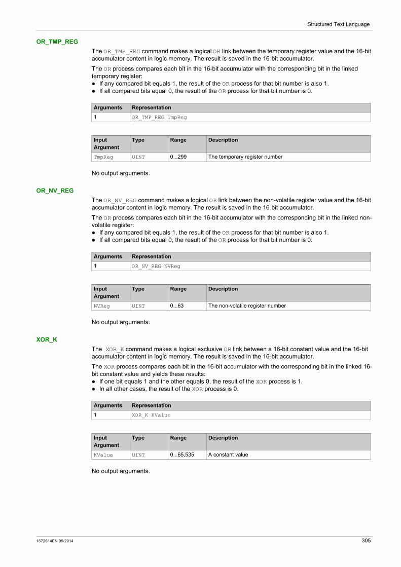
Structured Text Language
OR_TMP_REG
The OR_TMP_REG command makes a logical OR link between the temporary register value and the 16-bit accumulator content in logic memory. The result is saved in the 16-bit accumulator.
The OR process compares each bit in the 16-bit accumulator with the corresponding bit in the linked temporary register: If any compared bit equals 1, the result of the OR process for that bit number is also 1. If all compared bits equal 0, the result of the OR process for that bit number is 0.
No output arguments.
OR_NV_REG
The OR_NV_REG command makes a logical OR link between the non-volatile register value and the 16-bit accumulator content in logic memory. The result is saved in the 16-bit accumulator.
The OR process compares each bit in the 16-bit accumulator with the corresponding bit in the linked non-volatile register: If any compared bit equals 1, the result of the OR process for that bit number is also 1. If all compared bits equal 0, the result of the OR process for that bit number is 0.
No output arguments.
XOR_K
The XOR_K command makes a logical exclusive OR link between a 16-bit constant value and the 16-bit accumulator content in logic memory. The result is saved in the 16-bit accumulator.
The XOR process compares each bit in the 16-bit accumulator with the corresponding bit in the linked 16-bit constant value and yields these results: If one bit equals 1 and the other equals 0, the result of the XOR process is 1. In all other cases, the result of the XOR process is 0.
No output arguments.
Arguments Representation
1 OR_TMP_REG TmpReg
Input Argument
Type Range Description
TmpReg UINT 0...299 The temporary register number
Arguments Representation
1 OR_NV_REG NVReg
Input Argument
Type Range Description
NVReg UINT 0...63 The non-volatile register number
Arguments Representation
1 XOR_K KValue
Input Argument
Type Range Description
KValue UINT 0...65,535 A constant value
1672614EN 09/2014 305

Structured Text Language
XOR_REG
The XOR_REG command makes a logical exclusive OR link between the register value and the 16-bit accumulator content in logic memory. The result is saved in the 16-bit accumulator.
The XOR process compares each bit in the 16-bit accumulator with the corresponding bit in the linked register and yields these results: If one bit equals 1 and the other equals 0, the result of the XOR process is 1. In all other cases, the result of the XOR process is 0.
No output arguments.
XOR_TMP_REG
The XOR_TMP_REG command makes a logical exclusive OR link between the temporary register value and the 16-bit accumulator content in logic memory. The result is saved in the 16-bit accumulator.
The XOR process compares each bit in the 16-bit accumulator with the corresponding bit in the linked temporary register and yields these results: If one bit equals 1 and the other equals 0, the result of the XOR process is 1. In all other cases, the result of the XOR process is 0.
No output arguments.
XOR_NV_REG
The XOR_NV_REG command makes a logical exclusive OR link between the non-volatile register value and the 16-bit accumulator content in logic memory. The result is saved in the 16-bit accumulator.
The XOR process compares each bit in the 16-bit accumulator with the corresponding bit in the linked non-volatile register and yields these results: If one bit equals 1 and the other equals 0, the result of the XOR process is 1. In all other cases, the result of the XOR process is 0.
No output arguments.
Arguments Representation
1 XOR_REG RegAddr
Input Argument
Type Range Description
RegAddr UINT 0...1399 The register address
Arguments Representation
1 XOR_TMP_REG TmpReg
Input Argument
Type Range Description
TmpReg UINT 0...299 The temporary register number
Arguments Representation
1 XOR_NV_REG NVReg
Input Argument
Type Range Description
NVReg UINT 0...63 The non-volatile register number
306 1672614EN 09/2014
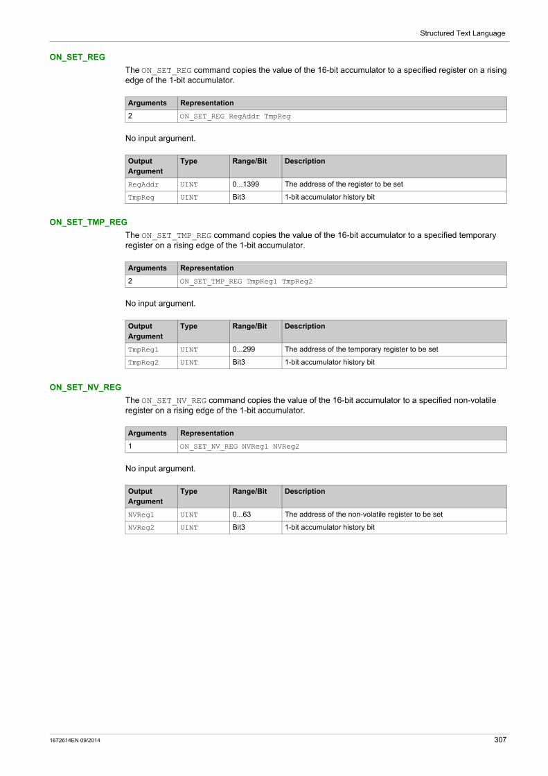
Structured Text Language
ON_SET_REG
The ON_SET_REG command copies the value of the 16-bit accumulator to a specified register on a rising edge of the 1-bit accumulator.
No input argument.
ON_SET_TMP_REG
The ON_SET_TMP_REG command copies the value of the 16-bit accumulator to a specified temporary register on a rising edge of the 1-bit accumulator.
No input argument.
ON_SET_NV_REG
The ON_SET_NV_REG command copies the value of the 16-bit accumulator to a specified non-volatile register on a rising edge of the 1-bit accumulator.
No input argument.
Arguments Representation
2 ON_SET_REG RegAddr TmpReg
Output Argument
Type Range/Bit Description
RegAddr UINT 0...1399 The address of the register to be set
TmpReg UINT Bit3 1-bit accumulator history bit
Arguments Representation
2 ON_SET_TMP_REG TmpReg1 TmpReg2
Output Argument
Type Range/Bit Description
TmpReg1 UINT 0...299 The address of the temporary register to be set
TmpReg2 UINT Bit3 1-bit accumulator history bit
Arguments Representation
1 ON_SET_NV_REG NVReg1 NVReg2
Output Argument
Type Range/Bit Description
NVReg1 UINT 0...63 The address of the non-volatile register to be set
NVReg2 UINT Bit3 1-bit accumulator history bit
1672614EN 09/2014 307

Structured Text Language
Timer Logic Commands
Overview
The custom logic editor uses the following timer commands: TIMER_SEC TIMER_TENTHS TIMER_K_SEC TIMER_K_TENTHS
TIMER_SEC
The TIMER_SEC command: counts time in seconds, up to the number of counts specified by a temporary register calculates the end time in a second temporary register is enabled by, and reports its counting status to, a third temporary register
Arguments Representation
3 TIMER_SEC TmpReg1 TmpReg2 TmpReg3
Input Argument
Type Range/Bit Description
TmpReg1 UINT 0...65,535 Timer preset value
TmpReg3 UINT Bit0 Starts the timer on a rising edge Stops the timer on a falling edge
Output Argument
Type Range/Bit Description
TmpReg2 UINT 0...65,535 Calculated end time
TmpReg3 UINT Bit1 Timer done: bit set when timer reaches TmpReg2 bit reset when: TmpReg3.Bit0 is reset power is cycled
Bit2 Timer execution in progressBit reset when timer reaches TmpReg2
Bit3 TmpReg3.Bit0 history bit
Bit4 Reserved
308 1672614EN 09/2014
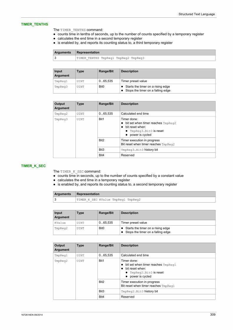
Structured Text Language
TIMER_TENTHS
The TIMER_TENTHS command: counts time in tenths of seconds, up to the number of counts specified by a temporary register calculates the end time in a second temporary register is enabled by, and reports its counting status to, a third temporary register
TIMER_K_SEC
The TIMER_K_SEC command: counts time in seconds, up to the number of counts specified by a constant value calculates the end time in a temporary register is enabled by, and reports its counting status to, a second temporary register
Arguments Representation
3 TIMER_TENTHS TmpReg1 TmpReg2 TmpReg3
Input Argument
Type Range/Bit Description
TmpReg1 UINT 0...65,535 Timer preset value
TmpReg3 UINT Bit0 Starts the timer on a rising edge Stops the timer on a falling edge
Output Argument
Type Range/Bit Description
TmpReg2 UINT 0...65,535 Calculated end time
TmpReg3 UINT Bit1 Timer done: bit set when timer reaches TmpReg2 bit reset when: TmpReg3.Bit0 is reset power is cycled
Bit2 Timer execution in progressBit reset when timer reaches TmpReg2
Bit3 TmpReg3.Bit0 history bit
Bit4 Reserved
Arguments Representation
3 TIMER_K_SEC KValue TmpReg1 TmpReg2
Input Argument
Type Range/Bit Description
KValue UINT 0...65,535 Timer preset value
TmpReg2 UINT Bit0 Starts the timer on a rising edge Stops the timer on a falling edge
Output Argument
Type Range/Bit Description
TmpReg1 UINT 0...65,535 Calculated end time
TmpReg2 UINT Bit1 Timer done: bit set when timer reaches TmpReg1 bit reset when: TmpReg2.Bit0 is reset power is cycled
Bit2 Timer execution in progressBit reset when timer reaches TmpReg1
Bit3 TmpReg2.Bit0 history bit
Bit4 Reserved
1672614EN 09/2014 309

Structured Text Language
TIMER_K_TENTHS
The TIMER_K_TENTHS command: counts time in tenths of seconds, up to the number of counts specified by a constant value calculates the end time in a temporary register is enabled by, and reports its counting status to, a second temporary register
Arguments Representation
3 TIMER_K_TENTHS KValue TmpReg1 TmpReg2
Input Argument
Type Range/Bit Description
KValue UINT 0...65,535 Timer preset value
TmpReg2 UINT Bit0 Starts the timer on a rising edge Stops the timer on a falling edge
Output Argument
Type Range/Bit Description
TmpReg1 UINT 0...65,535 Calculated end time
TmpReg2 UINT Bit1 Timer done: bit set when timer reaches TmpReg1 bit reset when: TmpReg2.Bit0 is reset power is cycled
Bit2 Timer execution in progressBit reset when timer reaches TmpReg1
Bit3 TmpReg2.Bit0 history bit
Bit4 Reserved
310 1672614EN 09/2014
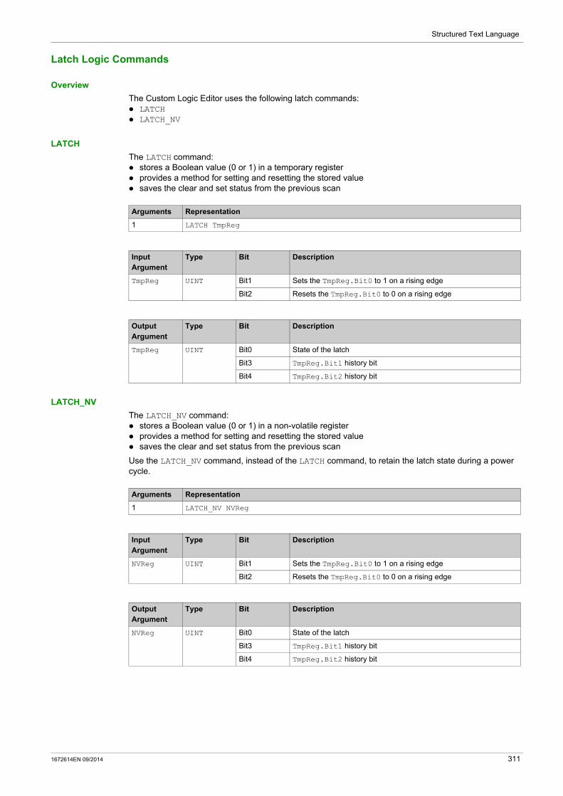
Structured Text Language
Latch Logic Commands
Overview
The Custom Logic Editor uses the following latch commands: LATCH LATCH_NV
LATCH
The LATCH command: stores a Boolean value (0 or 1) in a temporary register provides a method for setting and resetting the stored value saves the clear and set status from the previous scan
LATCH_NV
The LATCH_NV command: stores a Boolean value (0 or 1) in a non-volatile register provides a method for setting and resetting the stored value saves the clear and set status from the previous scan
Use the LATCH_NV command, instead of the LATCH command, to retain the latch state during a power cycle.
Arguments Representation
1 LATCH TmpReg
Input Argument
Type Bit Description
TmpReg UINT Bit1 Sets the TmpReg.Bit0 to 1 on a rising edge
Bit2 Resets the TmpReg.Bit0 to 0 on a rising edge
Output Argument
Type Bit Description
TmpReg UINT Bit0 State of the latch
Bit3 TmpReg.Bit1 history bit
Bit4 TmpReg.Bit2 history bit
Arguments Representation
1 LATCH_NV NVReg
Input Argument
Type Bit Description
NVReg UINT Bit1 Sets the TmpReg.Bit0 to 1 on a rising edge
Bit2 Resets the TmpReg.Bit0 to 0 on a rising edge
Output Argument
Type Bit Description
NVReg UINT Bit0 State of the latch
Bit3 TmpReg.Bit1 history bit
Bit4 TmpReg.Bit2 history bit
1672614EN 09/2014 311

Structured Text Language
Counter Logic Commands
Overview
The custom logic editor uses the following counter logic commands: COUNTER COUNTER_NV
COUNTER
The COUNTER command: increments or decrements a count value provides a method for setting the count value to a preset value indicates when the count value equals 0 indicates the relationship between the count value and the preset value - equal to, greater than or less
than saves the increment, decrement and set status from the previous scan
Arguments Representation
3 COUNTER TmpReg1 KValue TmpReg2
Input Argument
Type Range/Bit Description
KValue UINT 0...65,535 Counter preset value
TmpReg2 UINT Bit4 Increments the counter current value on a rising edge. Counter current value shall roll over from 65,535 to 0.
Bit5 Decrements the counter current value on a rising edge. Counter current value shall roll over from 0 to 65,535.
Bit6 Sets the current counter value to the preset value on a rising edge
Output Argument
Type Range/Bit Description
TmpReg1 UINT 0...65,535 Counter current value
TmpReg2 UINT Bit0 The counter current value is 0: TmpReg1=0
Bit1 The counter current value is lower than the preset value: TmpReg1<KValue
Bit2 The counter current value is equal to the preset value: TmpReg1=KValue
Bit3 The counter current value is greater than the preset value: TmpReg1>KValue
Bit7 TmpReg2.Bit4 history bit
Bit8 TmpReg2.Bit5 history bit
Bit9 TmpReg2.Bit6 history bit
312 1672614EN 09/2014
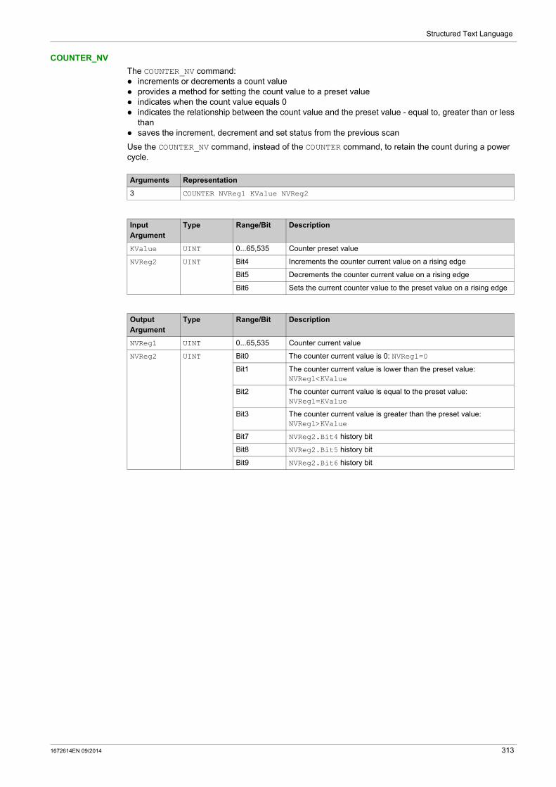
Structured Text Language
COUNTER_NV
The COUNTER_NV command: increments or decrements a count value provides a method for setting the count value to a preset value indicates when the count value equals 0 indicates the relationship between the count value and the preset value - equal to, greater than or less
than saves the increment, decrement and set status from the previous scan
Use the COUNTER_NV command, instead of the COUNTER command, to retain the count during a power cycle.
Arguments Representation
3 COUNTER NVReg1 KValue NVReg2
Input Argument
Type Range/Bit Description
KValue UINT 0...65,535 Counter preset value
NVReg2 UINT Bit4 Increments the counter current value on a rising edge
Bit5 Decrements the counter current value on a rising edge
Bit6 Sets the current counter value to the preset value on a rising edge
Output Argument
Type Range/Bit Description
NVReg1 UINT 0...65,535 Counter current value
NVReg2 UINT Bit0 The counter current value is 0: NVReg1=0
Bit1 The counter current value is lower than the preset value: NVReg1<KValue
Bit2 The counter current value is equal to the preset value: NVReg1=KValue
Bit3 The counter current value is greater than the preset value: NVReg1>KValue
Bit7 NVReg2.Bit4 history bit
Bit8 NVReg2.Bit5 history bit
Bit9 NVReg2.Bit6 history bit
1672614EN 09/2014 313

Structured Text Language
Math Logic Commands
Overview
The custom logic editor uses the following math commands: ON_ADD ON_SUB ON_MUL ON_DIV
ON_ADD
The ON_ADD command performs unsigned addition when the 1-bit accumulator transitions from 0 to 1. It adds the value from Argument 1 to the 16-bit accumulator value, then posts the result back to the value in Argument 1.
A status register: indicates an overflow if the result of the addition process exceeds 65,535 indicates the status of the 1-bit-accumulator from the previous scan
ON_SUB
The ON_SUB command performs unsigned subtraction when the 1-bit accumulator transitions from 0 to 1. It subtracts the 16-bit accumulator value from the value in Argument 1, then posts the result back to the value in Argument 1.
A status register: indicates an underflow if the result of the subtraction process is less than 0 indicates the status of the 1-bit-accumulator from the previous scan
Arguments Representation
2 ON_ADD TmpReg1 TmpReg2
Input Argument
Type Range/Bit Description
TmpReg1 UINT 0...65,535 Value to add to the 16-bit accumulator
Output Argument
Type Range/Bit Description
TmpReg1 UINT 0...65,535 Result of the addition operation
TmpReg2 UINT Bit0 Overflow: the result of the addition is greater than 65,535.In this case, the result of the addition is equal to Argument 1 + 65,536.
Bit3 1-bit accumulator history bit
Arguments Representation
2 ON_SUB TmpReg1 TmpReg2
Input Argument
Type Range/Bit Description
TmpReg1 UINT 0...65,535 Value to subtract from the 16-bit accumulator
Output Argument
Type Range/Bit Description
TmpReg1 UINT 0...65,535 Result of the subtraction operation
TmpReg2 UINT Bit0 Underflow: the result of the subtration is less than 0.In this case, the true result of the operation equals the value output to Argument 1 - 65,536.
Bit3 1-bit accumulator history bit
314 1672614EN 09/2014

Structured Text Language
ON_MUL
The ON_MUL command performs unsigned multiplication when the 1-bit accumulator transitions from 0 to 1. The ON_MUL procedure multiplies the value from Argument 2 against the 16-bit accumulator value, then posts the result back to Argument 1 (most significant word) and Argument 2 (least significant word).
A status register indicates the status of the 1-bit accumulator from the previous scan.
ON_DIV
The ON_DIV command performs unsigned division when the 1-bit accumulator transitions from 0 to 1. The ON_DIV procedure divides the combined value of Argument 1 and Argument 2 by the 16-bit accumulator value, then posts the result back to Argument 1 (most significant word) and Argument 2 (least significant word).
A status register indicates: an overflow if division is by 0 the status of the 1-bit-accumulator from the previous scan
Arguments Representation
3 ON_MUL TmpReg1 TmpReg2 TmpReg3
Input Argument
Type Range/Bit Description
TmpReg2 UINT 0...65,535 Value to be multiply with the 16-bit accumulator
Output Argument
Type Range/Bit Description
TmpReg1 and TmpReg2
UINT 0...65,535 Result of the multiplication operation: TmpReg1 holds the most significant word TmpReg2 holds the least significant word
TmpReg3 UINT Bit3 1-bit accumulator history bit
Arguments Representation
3 ON_DIV TmpReg1 TmpReg2 TmpReg3
Input Argument
Type Range/Bit Description
TmpReg1 and TmpReg2
UINT 0...65,535 Value to be divided by the 16-bit accumulator
Output Argument
Type Range/Bit Description
TmpReg1 and TmpReg2
UINT 0...65,535 Result of the division operation: TmpReg1 holds the most significant word TmpReg2 holds the least significant word
TmpReg3 UINT Bit0 Division by 0
Bit3 1-bit accumulator history bit
1672614EN 09/2014 315
Structured Text Language
Structured Text Program Examples
Section 7.3Structured Text Program Examples
Summary
This section shows the structured text program of 2 typical situations which you may need to use in your applications: Checking timers and multiply commands Creating a truth table
What Is in This Section?
This section contains the following topics:
Topic Page
How to Check Timers and Multiply Commands 317
How to Create a Truth Table 318
316 1672614EN 09/2014
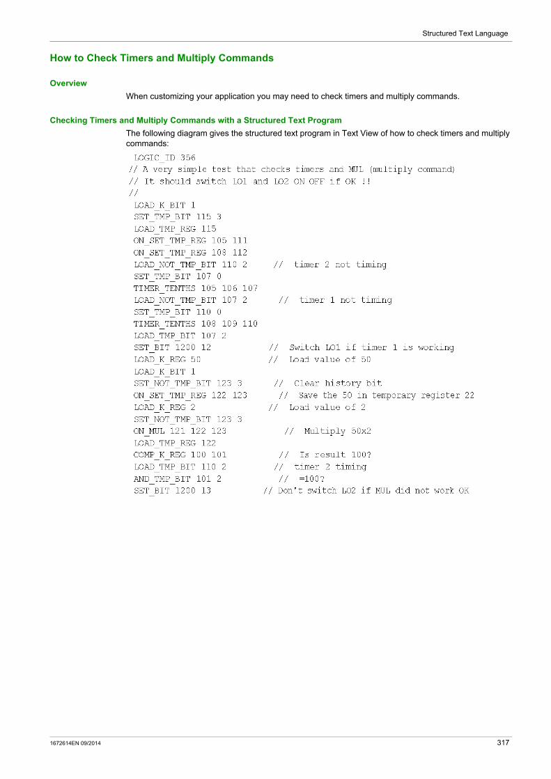
Structured Text Language
How to Check Timers and Multiply Commands
Overview
When customizing your application you may need to check timers and multiply commands.
Checking Timers and Multiply Commands with a Structured Text Program
The following diagram gives the structured text program in Text View of how to check timers and multiply commands:
1672614EN 09/2014 317

Structured Text Language
How to Create a Truth Table
Overview
When customizing your application you may need to create a truth table.
Creating a Truth Table with a Structured Text Program
The following diagram gives the structured Text program in Text View of the creation of a truth table:
318 1672614EN 09/2014
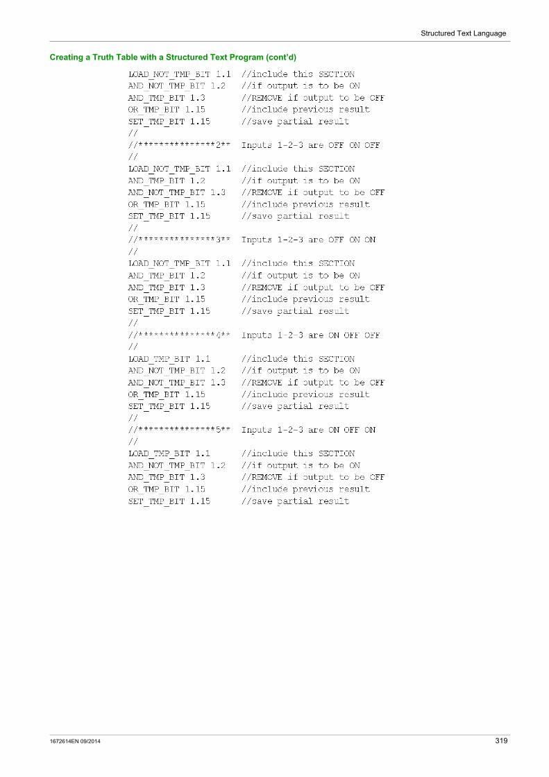
Structured Text Language
Creating a Truth Table with a Structured Text Program (cont’d)
1672614EN 09/2014 319

Structured Text Language
Creating a Truth Table with a Structured Text Program (cont’d)
320 1672614EN 09/2014

TeSys T DTM for FDT Container
Function Block Diagram Language
1672614EN 09/2014
Function Block Diagram Language
Chapter 8Function Block Diagram Language
Overview
The function block diagram editor enables you to create a custom logic program based on the function block diagram programming language.
What Is in This Chapter?
This chapter contains the following sections:
Section Topic Page
8.1 Overview of FBD Language 322
8.2 FBD Elements 324
8.3 Programming with the FBD Language 337
8.4 Manipulating FBD Blocks 342
8.5 FBD Editor Display Options 345
1672614EN 09/2014 321
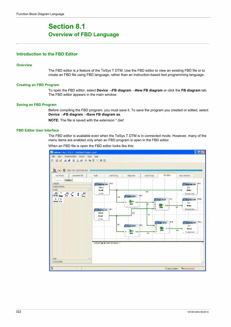
Function Block Diagram Language
Overview of FBD Language
Section 8.1Overview of FBD Language
Introduction to the FBD Editor
Overview
The FBD editor is a feature of the TeSys T DTM. Use the FBD editor to view an existing FBD file or to create an FBD file using FBD language, rather than an instruction-based text programming language.
Creating an FBD Program
To open the FBD editor, select Device →FB diagram →New FB diagram or click the FB diagram tab. The FBD editor appears in the main window.
Saving an FBD Program
Before compiling the FBD program, you must save it. To save the program you created or edited, select Device →FB diagram →Save FB diagram as.
NOTE: The file is saved with the extension *.Gef.
FBD Editor User Interface
The FBD editor is available even when the TeSys T DTM is in connected mode. However, many of the menu items are enabled only when an FBD program is open in the FBD editor.
When an FBD file is open the FBD editor looks like this:
322 1672614EN 09/2014

Function Block Diagram Language
Workspace
FBD programs are edited and created in the workspace.
The workspace is made up of 2 elements: blocks wires to link the blocks
Execution of FBD Programs
FBD programs are executed line by line, from the left to the right and from top to bottom. In the example below, the instructions are executed from instruction 1 to instruction 9, in the order indicated by the arrows.
1672614EN 09/2014 323

Function Block Diagram Language
FBD Elements
Section 8.2FBD Elements
Summary
This section describes in detail the FBD elements provided by the FBD editor, and their arguments.
What Is in This Section?
This section contains the following topics:
Topic Page
Computation Blocks 325
Inputs Blocks 327
Function Blocks 330
Logic Blocks 334
Outputs Blocks 335
324 1672614EN 09/2014

Function Block Diagram Language
Computation Blocks
Overview
The FBD editor uses various Computation blocks accessible through the Computation bar in the Toolbox:
NOTE: Placing cursor over the icon will reveal a tool tip defining the icon. This will help you distinguish which type of block is represented by that icon.
Compare Block
The block compares two 16-bit register values.
Add Block
The block performs an unsigned addition of two 16-bit register values.
Block Description
Compare
Add
Division
Multiplication
Subtraction
FBD Symbol Arguments Description
Inputs X: 16-bit unsigned register value (0...65,535). Y: 16-bit unsigned register value (0...65,535).
Outputs X < Y: ON/OFF temporary bit that is ON if the value X is less than the value Y.
X = Y: ON/OFF temporary bit that is ON if the value X is equal to the value Y.
X > Y: ON/OFF temporary bit that is ON if the value X is greater than the value Y.
FBD Symbol Arguments or Example
Description
Inputs X: 16-bit unsigned register value (0...65,535). Y: 16-bit unsigned register value (0...65,535).
Outputs Z: 16-bit unsigned register result (Z = X + Y). Overflow: ON or OFF value which when set ON caries a value of
65,536. The value is initialized to OFF.
Example Assuming X = 60,000 and Y = 7,000, the overflow will be ON because 60,000 + 7,000 = 67,000, which is superior to 65,536. The result Z is then equal to 1,464 (1,464 + 65,356 = 67,000).
1672614EN 09/2014 325

Function Block Diagram Language
Subtraction Block
The block performs an unsigned subtraction of two 16-bit register values.
Multiplication Block
The block performs an unsigned multiplication of two 16-bit register values.
Division Block
The block performs an unsigned division of two 16-bit register values.
FBD Symbol Arguments or Example
Description
Inputs X: 16-bit unsigned register value (0...65,535). Y: 16-bit unsigned register value (0...65,535).
Outputs Z: 16-bit unsigned register result (Z = X – Y). Underflow: ON or OFF value, which when set ON, caries a value of
negative 65,536. The value is initialized to OFF.
Example Assuming X = 5 and Y = 10, the underflow will be ON because the result is negative. The result Z is then equal to 65,531 (65,531 – 65,536 = –5)
FBD Symbol Arguments or Example
Description
Inputs X: 16-bit unsigned register value (0...65,535) Y: 16-bit unsigned register value (0...65,535)
Outputs Z(h): 16 most significant bits of the 32-bit result,Z(h) = (X * Y) / 65,536
Z(l): 16 least significant bits of the 32-bit result,Z(l) = (X * Y) – Z(h) * 65,536
Example Assuming X = 20,000 and Y = 10, the result will be Z(h) = 3 and Z(l) = 3,392 because 200,000 = 3 * 65,536 + 3,392
FBD Symbol Arguments or Example
Description
Inputs X(h): 16 most significant bits of an unsigned register value (0...65,535).
X(l): 16 least significant bits of an unsigned register value (0...65,535).
Y: 16-bit unsigned register divisor (0...65,535).
Outputs Z(h): 16 most significant bits of the 32-bit quotient,Z(h) = (X / Y) / 65,536
Z(l): 16 least significant bits of the 32-bit quotient,Z(l) = (X / Y) – Z(h) * 65,536
Error: ON or OFF value, which is set ON when a division by zero occurs. This value is initialized to OFF.
Example Assuming X(h) = 3, X(l) = 3,392 and Y = 40, the result will be Z(h) = 0 and Z(l) = 5,000 because X(h) * 65,536 + X(l) = 3 * 65,536 + 3,392 = 200,000 and 200,000 /Y = 5,000 = 0 * 65,536 + 5,000
326 1672614EN 09/2014
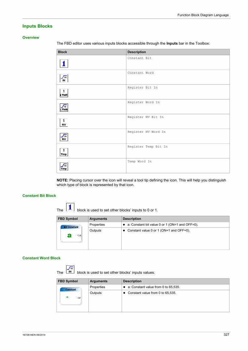
Function Block Diagram Language
Inputs Blocks
Overview
The FBD editor uses various inputs blocks accessible through the Inputs bar in the Toolbox:
NOTE: Placing cursor over the icon will reveal a tool tip defining the icon. This will help you distinguish which type of block is represented by that icon.
Constant Bit Block
The block is used to set other blocks’ inputs to 0 or 1.
Constant Word Block
The block is used to set other blocks’ inputs values.
Block Description
Constant Bit
Constant Word
Register Bit In
Register Word In
Register NV Bit In
Register NV Word In
Register Temp Bit In
Temp Word In
FBD Symbol Arguments Description
Properties a: Constant bit value 0 or 1 (ON=1 and OFF=0).
Outputs Constant value 0 or 1 (ON=1 and OFF=0).
FBD Symbol Arguments Description
Properties a: Constant value from 0 to 65,535.
Outputs Constant value from 0 to 65,535.
1672614EN 09/2014 327
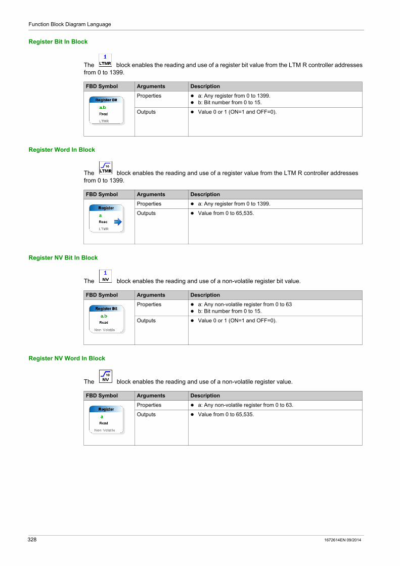
Function Block Diagram Language
Register Bit In Block
The block enables the reading and use of a register bit value from the LTM R controller addresses from 0 to 1399.
Register Word In Block
The block enables the reading and use of a register value from the LTM R controller addresses from 0 to 1399.
Register NV Bit In Block
The block enables the reading and use of a non-volatile register bit value.
Register NV Word In Block
The block enables the reading and use of a non-volatile register value.
FBD Symbol Arguments Description
Properties a: Any register from 0 to 1399. b: Bit number from 0 to 15.
Outputs Value 0 or 1 (ON=1 and OFF=0).
FBD Symbol Arguments Description
Properties a: Any register from 0 to 1399.
Outputs Value from 0 to 65,535.
FBD Symbol Arguments Description
Properties a: Any non-volatile register from 0 to 63 b: Bit number from 0 to 15.
Outputs Value 0 or 1 (ON=1 and OFF=0).
FBD Symbol Arguments Description
Properties a: Any non-volatile register from 0 to 63.
Outputs Value from 0 to 65,535.
328 1672614EN 09/2014
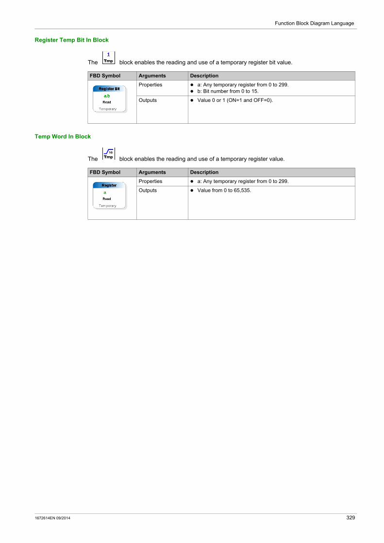
Function Block Diagram Language
Register Temp Bit In Block
The block enables the reading and use of a temporary register bit value.
Temp Word In Block
The block enables the reading and use of a temporary register value.
FBD Symbol Arguments Description
Properties a: Any temporary register from 0 to 299. b: Bit number from 0 to 15.
Outputs Value 0 or 1 (ON=1 and OFF=0).
FBD Symbol Arguments Description
Properties a: Any temporary register from 0 to 299.
Outputs Value from 0 to 65,535.
1672614EN 09/2014 329

Function Block Diagram Language
Function Blocks
Overview
The FBD editor uses various functions blocks accessible through the function bar in the Toolbox:
NOTE: Placing cursor over the icon will reveal a tool tip defining the icon. This will help you distinguish which type of block is represented by that icon.
CALL_EOM Block
The function executes a pre-defined operating mode in the customized program.
Block Description
CALL_EOM
Counter
Counter NV
Volatile Latch
Non Volatile Latch
Multiplexer
TimerSeconds
TimerTenthSeconds
FBD Symbol Arguments Description
Properties Property 1 = Embedded operating mode (EOM): Overload (1) Independent (2) Reverser (3) 2-Step (4) 2-Speed (5)
Property 2 = Terminal strip control: ON = 3-wire terminal strip control (3W) OFF = 2-wire terminal strip control (2W)
330 1672614EN 09/2014

Function Block Diagram Language
Counter Block
The function performs a comparative count, saving both the counter current and counter preset values to temporary registers.
NOTE: The Counter preset value range is from 0 to 65,535. Cascading counters and compare functions can be used if you need larger values or multiple preset values.
Counter NV Block
The function performs a comparative count, saving both the counter current and counter preset values to non-volatile registers.
NOTE: The Counter preset value range is from 0 to 65,535. Cascading counters and compare functions can be used if you need larger values or multiple preset values
Volatile Latch Block
The function records and retains signal history in a temporary register.
FBD Symbol Arguments Description
Properties K: Counter preset value (UINT 0...65,535).
Inputs Inc: Increments the counter current value on a rising edge. Counter current value shall roll over from 65,535 to 0.
Dec: Decrements the counter current value on a rising edge. Counter current value shall roll over from 0 to 65,535.
Set: Sets the current counter value to the preset value on a rising edge.
Outputs Count: Counter current value (UINT 0...65,535). Count is initialized to zero on power-up.
<K: The counter current value is lower than the preset value K. =K: The counter current value is equal to the preset value K. >K: The counter current value is greater than the preset value K.
FBD Symbol Arguments Description
Properties K: Counter preset value (UINT 0...65,535).
Inputs Inc: Increments the counter current value on a rising edge. Counter current value shall roll over from 65,535 to 0.
Dec: Decrements the counter current value on a rising edge. Counter current value shall roll over from 0 to 65,535.
Set: Sets the current counter value to the preset value on a rising edge.
Outputs Count: Counter current value (UINT 0...65,535). This value is saved in non-volatile memory and initialized to the previous value on power-up.
<K: The counter current value is lower than the preset value K. =K: The counter current value is equal to the preset value K. >K: The counter current value is greater than the preset value K.
FBD Symbol Arguments Description
Inputs Set: ON/OFF input value. The latch value is set ON when this input transitions from OFF to ON.
Clear: ON/OFF input value. The latch value is set OFF when this input transitions from OFF to ON.
Outputs Q: ON or OFF latch value which represents the state of this latch. This value remains ON/OFF until the next rising edge of Set or Clear. This value is initialized to OFF.
1672614EN 09/2014 331

Function Block Diagram Language
Non Volatile Latch Block
The function records and retains signal history in a non-volatile register.
Multiplexer Block
The function enables you to choose between two 16-bit unsigned values.
Timer Seconds Block
The function measures time in intervals of seconds.
FBD Symbol Arguments Description
Inputs Set: ON/OFF input value. The latch value is set ON when this input transitions from OFF to ON.
Clear: ON/OFF input value. The latch value is set OFF when this input transitions from OFF to ON.
Outputs Q: ON or OFF non-volatile register bit value that represents the state of this latch. This value remains ON/OFF until the next rising edge of Set or Clear. This value is saved in non-volatile memory and initialized to previous state on power-up.
FBD Symbol Arguments Description
Inputs A: 16-bit unsigned value (0...65,535). B: 16-bit unsigned value (0...65,535). A/B: ON/OFF input value that selects value A or B.
Outputs Out: Selected 16-bit value: If A/B is ON then Out = A. If A/B is OFF then Out = B.
FBD Symbol Timing Diagram Arguments Description
Inputs Time: 16-bit unsigned value (0...65,535) that specifies time period in seconds.
Enable: ON/OFF input value. The time period is loaded on the rising edge of the Enable input. Time measuring continues while Enable is ON. Timing stops and outputs are OFF when Enable is OFF.
Outputs Timed: ON/OFF value which turns ON while Enable is ON and time period expires. It is OFF while measuring time or while Enable is OFF.
Timing: ON/OFF value that is ON while Enable is ON and while measuring time. It is OFF after time period expires or Enable is OFF.
Note: Both outputs can never be simultaneously ON.
332 1672614EN 09/2014

Function Block Diagram Language
Timer TenthSeconds Block
The function measures time in intervals of tenths of seconds.
FBD Symbol Timing Diagram Arguments Description
Inputs Time: 16-bit unsigned value (0...65,535) that specifies time periods in tenths of seconds.
Enable: ON/OFF input value. The time period is loaded on the rising edge of the Enable input. Time measuring continues while Enable is ON. Timing stops and outputs are OFF when Enable is OFF.
Outputs Timed: ON/OFF value that turns ON while Enable is ON and time period expires. It is OFF while measuring time or while Enable is OFF.
Timing: ON/OFF value which is ON while Enable is ON and while measuring time. It is OFF after time period expires or Enable is OFF.
Note: Both outputs can never be simultaneously ON.
1672614EN 09/2014 333

Function Block Diagram Language
Logic Blocks
Overview
The FBD editor uses various logic blocks accessible through the Logic blocks bar in the Toolbox:
NOTE: Placing cursor over the icon will reveal a tool tip defining the icon. This will help you distinguish which type of block is represented by that icon.
Function Icon FBD Symbol Description
AND If all the inputs (ON or OFF values, respectively 1 or 0) are ON or not connected, the output is ON.If at least one input is OFF, the output is OFF.
NOTE: unconnected inputs are assumed to be ON.
NOT If the input (ON or OFF values, respectively 1 or 0) is ON, the output is OFF.If the input is OFF, the output is ON.
OR If at least one input (ON or OFF values, respectively 1 or 0) is ON, the output is ON.If all the inputs are OFF or not connected, the output is OFF.
NOTE: unconnected inputs are assumed to be OFF.
334 1672614EN 09/2014
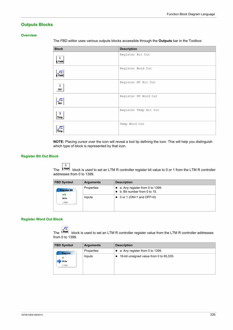
Function Block Diagram Language
Outputs Blocks
Overview
The FBD editor uses various outputs blocks accessible through the Outputs bar in the Toolbox:
NOTE: Placing cursor over the icon will reveal a tool tip defining the icon. This will help you distinguish which type of block is represented by that icon.
Register Bit Out Block
The block is used to set an LTM R controller register bit value to 0 or 1 from the LTM R controller addresses from 0 to 1399.
Register Word Out Block
The block is used to set an LTM R controller register value from the LTM R controller addresses from 0 to 1399.
Block Description
Register Bit Out
Register Word Out
Register NV Bit Out
Register NV Word Out
Register Temp Bit Out
Temp Word Out
FBD Symbol Arguments Description
Properties a: Any register from 0 to 1399. b: Bit number from 0 to 15.
Inputs 0 or 1 (ON=1 and OFF=0)
FBD Symbol Arguments Description
Properties a: Any register from 0 to 1399.
Inputs 16-bit unsigned value from 0 to 65,535.
1672614EN 09/2014 335

Function Block Diagram Language
Register NV Bit Out Block
The block is used to set a non-volatile register bit value to 0 or 1.
Register NV Word Out Block
The block is used to set a non-volatile register value.
Register Temp Bit Out Block
The block is used to set a temporary register bit value to 0 or 1.
Temp Word Out Block
The block is used to set a temporary register value.
FBD Symbol Arguments Description
Properties a: Any non-volatile register from 0 to 63. b: Bit number from 0 to 15.
Inputs 0 or 1 (ON=1 and OFF=0)
FBD Symbol Arguments Description
Properties a: Any non-volatile register from 0 to 63.
Inputs 16-bit unsigned value from 0 to 65,535
FBD Symbol Arguments Description
Properties a: Any temporary register from 0 to 299. b: Bit number from 0 to 15.
Inputs 0 or 1 (ON=1 and OFF=0)
FBD Symbol Arguments Description
Properties a: Any temporary register from 0 to 299.
Inputs 16-bit unsigned value from 0 to 65,535
336 1672614EN 09/2014

Function Block Diagram Language
Programming with the FBD Language
Section 8.3Programming with the FBD Language
Summary
This section describes how to create and modify a program using the FBD language.
What Is in This Section?
This section contains the following topics:
Topic Page
Inserting FBD Blocks 338
Creation of Links between Blocks 339
FBD Blocks Properties 340
FBD Resource Management 341
1672614EN 09/2014 337

Function Block Diagram Language
Inserting FBD Blocks
Overview
To create an FBD program, insert blocks into the workspace, then link them together. All types of blocks can be placed in the workspace.
Inserting Blocks from the Toolbox
The following procedure describes how to insert a block from the toolbox into the workspace:
Inserting Blocks from the Workspace
The following procedure describes how to insert a block directly from the workspace:
Step Action
1 Select Device → FB diagram → View → Toolbox or click the Toolbox tab on the left side.
2 Select the type of block to insert: Computation Inputs Function Blocks Logic Outputs
3 Left-click on the icon corresponding to the block to insert.
4 Drag and drop the block from the toolbox to the workspace.
5 Position the block in the required location on the workspace.
6 Repeat steps 2 to 5 to insert all the blocks required for the program.
Step Action
1 Right-click anywhere on a blank space in the workspace.Result: A menu opens and enables you to select the type of block you wish to insert.
2 Select the type of block to insert: Computation Inputs Function Blocks Logic Outputs
3 Left-click on the block you wish to insert.
4 Position the block in the required location in the workspace.
5 Repeat steps 1 to 5 to insert all the blocks required for the program.
338 1672614EN 09/2014
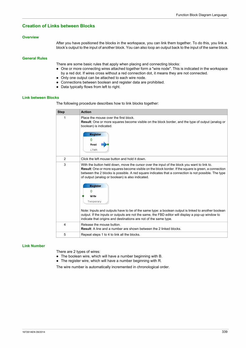
Function Block Diagram Language
Creation of Links between Blocks
Overview
After you have positioned the blocks in the workspace, you can link them together. To do this, you link a block’s output to the input of another block. You can also loop an output back to the input of the same block.
General Rules
There are some basic rules that apply when placing and connecting blocks: One or more connecting wires attached together form a "wire node". This is indicated in the workspace
by a red dot. If wires cross without a red connection dot, it means they are not connected. Only one output can be attached to each wire node. Connections between boolean and register data are prohibited. Data typically flows from left to right.
Link between Blocks
The following procedure describes how to link blocks together:
Link Number
There are 2 types of wires: The boolean wire, which will have a number beginning with B. The register wire, which will have a number beginning with R.
The wire number is automatically incremented in chronological order.
Step Action
1 Place the mouse over the first block.Result: One or more squares become visible on the block border, and the type of output (analog or boolean) is indicated.
2 Click the left mouse button and hold it down.
3 With the button held down, move the cursor over the input of the block you want to link to.Result: One or more squares become visible on the block border. If the square is green, a connection between the 2 blocks is possible. A red square indicates that a connection is not possible. The type of output (analog or boolean) is also indicated.
Note: Inputs and outputs have to be of the same type: a boolean output is linked to another boolean output. If the inputs or outputs are not the same, the FBD editor will display a pop-up window to indicate that origins and destinations are not of the same type.
4 Release the mouse button.Result: A line and a number are shown between the 2 linked blocks.
5 Repeat steps 1 to 4 to link all the blocks.
1672614EN 09/2014 339

Function Block Diagram Language
FBD Blocks Properties
Overview
Each of the blocks has a properties window. To display this window, left-click on a block.
The Properties window consists of several tabs, separated in 1 or 2 categories, depending on the type of block: General settings, which contain the block ID and comments (common to all types of blocks. Specific settings, depending on the type of block (register settings for registers, counter settings for
counters, etc.).
For example, if you wish to display non-volatile register properties, select a non-volatile register block and left-click on it. The following window is displayed:
Comments
In the Comment zone, in the white box on the right of Comments, you can enter a comment. Select any object or any free location in the workspace to save the comment.
Settings
Most blocks have a specific settings tab. In this tab, Set the specific settings of blocks. These settings are described in detail in the help for each of the FBD blocks.
Properties Display
The properties of each block can be displayed in 2 different ways:
by category, clicking or
by alphabetical order, clicking .
340 1672614EN 09/2014

Function Block Diagram Language
FBD Resource Management
Overview
The LTM R controller memory is equipped with the following resources: Logic memory space size equal to 8,192 words 300 temporary registers 64 non-volatile registers
Reserved Resources
When a custom logic program is developed using the structured text editor, all resources are available, whereas, when using the FBD editor, some temporary and non-volatile registers are reserved for use by the FBD compiler.
Register Allocation
The following table lists all reserved registers and their allocation. It also indicates how these registers are controlled:
Register Type Address Range
Controlled by Description
Temporary 0...69 The user Temporary storage of bit and registers assigned by the user when creating an FBD program.
Temporary 70...299 The FBD compiler Reserved temporary registers for use by the compiler.
Non-volatile 0...31 The user Non-volatile bits or registers assigned by the user when creating an FBD program.
Non-volatile 32...63 The FBD compiler Reserved non-volatile registers for use by the compiler.
1672614EN 09/2014 341
Function Block Diagram Language
Manipulating FBD Blocks
Section 8.4Manipulating FBD Blocks
Summary
This section describes the manner in which blocks in the workspace can be manipulated, including how to select, move, duplicate or delete blocks.
What Is in This Section?
This section contains the following topics:
Topic Page
How to Select Blocks 343
How to Delete and Duplicate Objects 344
342 1672614EN 09/2014

Function Block Diagram Language
How to Select Blocks
Overview
When you add blocks to the workspace, you can select them to reposition them within the workspace.
How to Select One or More Blocks
The following table describes how to select one or more blocks:
If you would like to select... Then
An isolated block Click block.
Several contiguous blocks Frame the blocks to be selected by defining a selection zone.Result: All of the selected blocks are highlighted with an orange outline.
Several blocks in different areas of the workspace
Press the SHIFT key, then click the blocks to be selected while continuing to hold down the SHIFT key.Result: All of the selected blocks are highlighted with an orange outline.
All objects including wires Select Device → FB diagram → FBD editor → Select allNote: The keyboard shortcut CTRL+A can also be used to select all objects.
1672614EN 09/2014 343
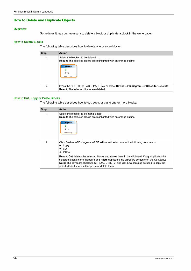
Function Block Diagram Language
How to Delete and Duplicate Objects
Overview
Sometimes it may be necessary to delete a block or duplicate a block in the workspace.
How to Delete Blocks
The following table describes how to delete one or more blocks:
How to Cut, Copy or Paste Blocks
The following table describes how to cut, copy, or paste one or more blocks:
Step Action
1 Select the block(s) to be deletedResult: The selected blocks are highlighted with an orange outline.
2 Press the DELETE or BACKSPACE key or select Device → FB diagram → FBD editor → Delete.Result: The selected blocks are deleted.
Step Action
1 Select the block(s) to be manipulated.Result: The selected blocks are highlighted with an orange outline.
2 Click Device → FB diagram → FBD editor and select one of the following commands: Copy Cut Paste
Result: Cut deletes the selected blocks and stores them in the clipboard. Copy duplicates the selected blocks in the clipboard and Paste duplicates the clipboard contents on the workspace.Note: The keyboard shortcuts CTRL+C, CTRL+V, and CTRL+X can also be used to copy the selected blocks, and either paste or delete them.
344 1672614EN 09/2014

Function Block Diagram Language
FBD Editor Display Options
Section 8.5FBD Editor Display Options
Summary
The following section describes the different FBD editor display options.
What Is in This Section?
This section contains the following topics:
Topic Page
Other Display Options 346
Workspace Appearance and Graph Options 347
1672614EN 09/2014 345
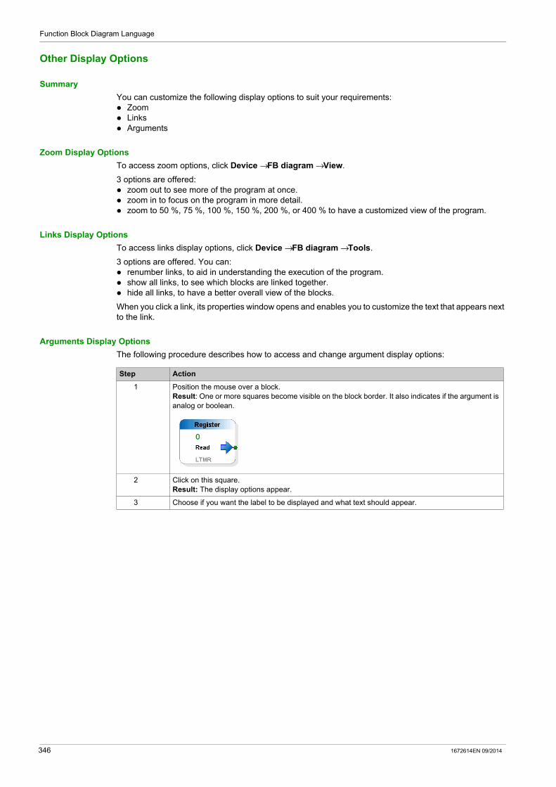
Function Block Diagram Language
Other Display Options
Summary
You can customize the following display options to suit your requirements: Zoom Links Arguments
Zoom Display Options
To access zoom options, click Device → FB diagram → View.
3 options are offered: zoom out to see more of the program at once. zoom in to focus on the program in more detail. zoom to 50 %, 75 %, 100 %, 150 %, 200 %, or 400 % to have a customized view of the program.
Links Display Options
To access links display options, click Device → FB diagram → Tools.
3 options are offered. You can: renumber links, to aid in understanding the execution of the program. show all links, to see which blocks are linked together. hide all links, to have a better overall view of the blocks.
When you click a link, its properties window opens and enables you to customize the text that appears next to the link.
Arguments Display Options
The following procedure describes how to access and change argument display options:
Step Action
1 Position the mouse over a block.Result: One or more squares become visible on the block border. It also indicates if the argument is analog or boolean.
2 Click on this square.Result: The display options appear.
3 Choose if you want the label to be displayed and what text should appear.
346 1672614EN 09/2014

Function Block Diagram Language
Workspace Appearance and Graph Options
Summary
The FBD editor enables you to customize the workspace by changing its appearance and graph options.
Appearance and Graph Options
To access appearance and graph options, left-click anywhere in the workspace, except on an object.
Appearance Options
The following table lists all the possible appearance customization options:
Graph Options
The following table lists all the possible graph customization options:
Display Grid
You may wish to display the grid lines. In order to do so, click Device → FB diagram → View → Show grid.
Appearance Option Description Possible Choices
Background Color Enables you to set the background color of the workspace by clicking the box where the color is displayed.
Choose between the colors available in the Custom, Web, and System tabs.
Background Image Path
Enables you to insert an image from your hard disk drive or any removable device and to define it as the background.
Any image you select as the background.Note: Only possible when the background type is set to image.
Background Type Enables you to set the background type. Choose between a flat color, gradient, or image background.
Enable Context Menu Shows or hides the context menu. True or false
Enable Tooltip Shows or hides tooltips. True or false
Gradient Bottom Enables you to set the color of the bottom of the gradient.
Choose between the colors available in the Custom, Web, and System tabs.Note: Only possible when the background type is set to gradient.
Gradient Top Enables you to set the color of the top of the gradient.
Choose between the colors available in the Custom, Web, and System tabs. Note: Only possible when the background type is set to gradient.
Gradient Mode Enables you to set the type of gradient Choose between horizontal, vertical, forward diagonal, and backward diagonal modes. Note: Only possible when the background type is set to gradient.
Restrict to Canvas Enables you to choose whether the FBD program should be kept inside the canvas.
True or false
Show Grid Enables you to choose whether the accurate grid is visible.
True or falseNote: This grid must not be confused with the grid line, which is accessed from the top-level View menu bar.
Snap Enables you to choose whether the objects are snapped with the grid. When set to true, if you move objects, they will move along the grid step.
True or false
Graph option Description Possible choices
Allow Add Connection Enables you to choose whether connections can be added to the workspace.
True or false
Allow Add Shape Enables you to choose whether blocks can be added to the workspace. True or false
Allow Delete Shape Enables you to choose whether blocks can be deleted. True or false
Allow Move Shape Enables you to choose whether blocks can be moved in the workspace. True or false
Locked Enables you to choose whether the FBD program can be edited. True or false
1672614EN 09/2014 347

Function Block Diagram Language
348 1672614EN 09/2014

TeSys T DTM for FDT Container
Compiling, Simulating, and Transferring a Program
1672614EN 09/2014
Compiling, Simulating, and Transferring a Program
Chapter 9Compiling, Simulating, and Transferring a Program
Overview
This chapter describes how to compile a structured text and a Function Block Diagram language program. It also describes the user interface windows involved in compiling the progam, simulating it with the logic simulator, and transferring it to the LTM R controller.
What Is in This Chapter?
This chapter contains the following topics:
Topic Page
Introduction 350
PCode Window 351
Error Window 352
LTM R Controller Logic Simulator 353
Initialization and Connection 355
Transferring Logic Files between the LTM R Controller and Custom Logic Editor 356
Custom Logic Program Transfer and Execution 358
1672614EN 09/2014 349

Compiling, Simulating, and Transferring a Program
Introduction
Compiling Overview
The customized program must be compiled before being downloaded to the LTM R controller: The programs in structured text language can be compiled directly. The programs in FBD language must be first converted in structured text language programs, before
compilation as structured text program.
Compiling includes a check for program errors, such as: syntax and structure errors symbols without corresponding addresses resources used by the program that are not available whether the program fits in available controller memory
Converting FBD to Structured Text
To compile into structured text the FBD program you created or edited, select Device → FB diagram → Compile FB diagram to ST program.
The program is automatically copied into the structured text editor if there is no error.
NOTE: Remember to save the FBD program in the FBD editor before converting it, because it is not possible to convert a structured text program file into an FBD file.
Compiling Structured Text
Follow these steps in order to compile the structured text program just created into PCode:
Step Action
1 Select Device → custom logic.
2 Click Compile custom program.
NOTE: If no errors are detected, the PCode window is displayed. Otherwise, the Error window is displayed.
350 1672614EN 09/2014
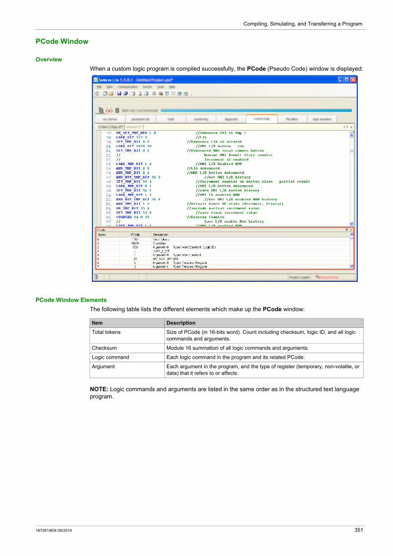
Compiling, Simulating, and Transferring a Program
PCode Window
Overview
When a custom logic program is compiled successfully, the PCode (Pseudo Code) window is displayed:
PCode Window Elements
The following table lists the different elements which make up the PCode window:
NOTE: Logic commands and arguments are listed in the same order as in the structured text language program.
Item Description
Total tokens Size of PCode (in 16-bits word). Count including checksum, logic ID, and all logic commands and arguments.
Checksum Module 16 summation of all logic commands and arguments.
Logic command Each logic command in the program and its related PCode.
Argument Each argument in the program, and the type of register (temporary, non-volatile, or data) that it refers to or affects.
1672614EN 09/2014 351

Compiling, Simulating, and Transferring a Program
Error Window
Overview
When a structured text language program is compiled, it may contain errors. In this case, the Error window is displayed:
Error Window Elements
In the example above, 2 mistakes were made.
The Error window indicates: the line numbers with errors, and a description of the error.
Error Types
The following list describes the different types of errors that may occur: syntax and structure errors logic commands without corresponding addresses resources used by the program that are not available program size is too large
352 1672614EN 09/2014

Compiling, Simulating, and Transferring a Program
LTM R Controller Logic Simulator
Overview
SoMove with the TeSys T DTM comes with the LTM R controller logic simulator. It enables to test the functioning of a structured text custom logic program before transferring it into the LTM R controller.
NOTE: To simulate an FBD program, it must be first converted and saved as a structured text program with the extension *.If.
Logic Simulator Interface
To open the logic simulator, click the logic simulator tab. The logic simulator is then displayed. In the right bottom corner, click Open Logic Function File to import your previously saved structured text program.
NOTE: When you import a program with syntax errors, an information window appears: correct all errors in the structure text editor and compile the program after corrections before starting the simulation.
The logic simulator with a loaded custom logic file is then displayed:
1 View window: used to display register 1200...1225.2 Used to display the status of registers 1200 and 458.3 Used to writes values to register 457.4 Used to write data in decimal format to any register address.
1672614EN 09/2014 353

Compiling, Simulating, and Transferring a Program
Register View
4 kinds of registers are displayed by the logic simulator: LTM R controller registers Temporary registers Non-volatile registers Logic memory
Those registers cannot be displayed at the same time. The Register View enables you to choose which ones you wish to monitor. In the example above, the content of the logic memory is displayed.
NOTE: By default, registers values are displayed in decimal code. Tick the Hex box if you would prefer them to be in hexadecimal code.
Logic Primitives Window
The Logic Primitives window displays the compiled PCode (see page 351).
NOTE: The PCode may read or write to any READ/WRITE register that is accessible by serial port communications.
View Window
The logic simulator displays the content of LTM R controller registers 1200...1225 in hexadecimal code (see part 1 on the illustration above). Registers 1200...1205 are the custom logic registers.
Registers 1200 and 458
The logic simulator displays the status of registers 1200 and 458 (See part 2 on the illustration above). The LTM R controller firmware then reads those PCode register values to direct device functions and physical outputs. For more information about those registers see the sections on Communication Variables in the Use chapter of the TeSys T LTM R Motor Management Controller User Manual.
The logic simulator displays an X in each output status checkbox to indicate that a bit value of ‘1’ exists in the output status register.
Register 457
The logic simulator enables to write values to register 457 bits (see part 3 on the illustration above). For more information about this register see the sections on Communication Variables in the Use chapter of the TeSys T LTM R Motor Management Controller User Manual. To be allowed to write to register 457, tick the Enables Inputs box.
Ticking a box on the left of a register bit will assign a value of 1 to this bit. Untick this box to assign 0 to this bit.
Example: If you tick the 3 first boxes, bits 457.0, 457.1, and 457.2 will get the value of 1. Click on the upper refresh button, and then check the value of register 457. You can see that it has the value of 7, which is in binary code 0000000000000111.
Writing to a Register Address
The logic simulator enables to write data in decimal format to any register address (see part 4 on the illustration above). Follow these steps to assign a value to a register:
Start a Trace
The Start a Trace box is an integrated debugging tool which captures the 1-bit and the 16-bit accumulator content.
Refresh
When you load your *.lf file into the logic simulator, it emulates the LTM R controller behavior. However, values are assigned when you load the file, regardless of changes you made in the logic simulator. Click the upper refresh button to take into accounts the changes made to registers’ values. Click the bottom refresh button to refresh the displayed PCode.
Step Action
1 Specify to which register you wish write data in the Address box.
2 Specify which value in decimal format you wish to assign in the Data box.
3 Click Write IMPR Reg.
354 1672614EN 09/2014

Compiling, Simulating, and Transferring a Program
Initialization and Connection
Initialization
When you connect the LTM R controller to the PC, the controller automatically initializes. This initialization process enables the controller and the PC to exchange identification information.
During this process, the custom logic editor indicates "Wait" until initialization is complete.
Connection
After initialization, the LTM R controller should automatically connect to the PC.
To verify that the controller is connected, check the status bar in the custom logic editor.
If the status bar reads Disconnected, then click Communication → Connect to Device or click the Connect to Device icon.
1 Communication menu2 Connect to Device icon3 Connection status
A progress bar briefly appears as your PC connects to the controller, and the word Connected appears in the status bar when the connection process successfully completes.
When the LTM R controller is connected, you can
upload custom logic files from the controller to SoMove with the TeSys T DTM for editing, download edited custom logic files from SoMove with the TeSys T DTM to the controller.
1672614EN 09/2014 355

Compiling, Simulating, and Transferring a Program
Transferring Logic Files between the LTM R Controller and Custom Logic Editor
File Transfer - Device Custom Logic to PC
To transfer the custom logic file from the LTM R controller to the custom logic editor:
Step Action
1 Ensure that the LTM R controller is connected to the PC (see page 355).
2
Select Device → custom logic → Device custom program to PC or click the icon to transfer the custom logic file from the LTM R controller to the custom logic editor.
3 When the custom logic file has been transferred, you can use the custom logic editor to edit it as a structured text program.
NOTE: Programs retrieved from LTM R controllers are in structured text only without comments. Programs such as FBD programs cannot be retrieved from the LTM R controller.
4 After your logic file edits are complete, save your work to a file. Select the Save command in either the icon bar or the File menu, browse to the correct location and click Save.
356 1672614EN 09/2014

Compiling, Simulating, and Transferring a Program
File Transfer Procedure - PC Custom Logic to Device
After you have edited and compiled your custom logic file, you can transfer the file to the LTM R controller. Before SoMove with the TeSys T DTM makes this transfer, the following conditions must be met: The custom logic file to transfer must be different than the logic file present in the LTM R controller, i.e.,
the software does not transfer the same program. Current must not be detected, that is, online current must be less than 10% of FLC.
If these conditions are not met, the file cannot be transferred to the controller.
To transfer a logic file from the custom logic editor to the LTM R controller:
Step Action
1 Ensure that the LTM R controller is connected to the PC (see page 355).
2 Ensure that the file to be transferred is in the main window. To open a file, select Open custom program from the custom logic submenu of the Device menu. Then, browse to the correct location and click Open.
3 Select Device → custom logic → Compile custom program to compile the structured text program.
4 After the compilation of the program, select Device → custom logic → PC custom program to device or click
the icon to transfer the logic file from the custom logic editor to the controller.
5 The transfer is now successful. A new window appears, click Ok to close it.
1672614EN 09/2014 357

Compiling, Simulating, and Transferring a Program
Custom Logic Program Transfer and Execution
Overview
Custom logic programs may be uploaded to or downloaded from the LTM R controller via SoMove with the TeSys T DTM. Only one custom logic program can be loaded into the LTM R controller at a time.
Transfer Validity Check
During the upload or download of a custom logic program, outputs are turned off and logic execution is stopped.
A specific mechanism is used to upload or download a custom logic file. This mechanism uses a size register, checksum, and custom logic ID code to ensure that an incomplete or corrupt logic function is detected. SoMove with the TeSys T DTM does not allow a logic file to be uploaded with a bad checksum. However, an interruption to the connection during the upload is detected by the checksum mechanism.
Custom Logic Program Selection
When a custom logic file is uploaded to the LTM R controller, that program can be selected by choosing "Custom" from the motor controller mode selection menu or by writing its logic ID code to register 540.
Custom Logic Program Replacement
In the situation where a custom logic program is replaced by another one with a different logic ID code and the installed custom program is selected, when the new program is uploaded, the value in register 540 is automatically changed to the new logic ID code. In cases, when a standard motor controller mode is currently active (i.e. Logic ID = 2 through 11) the value in register 540 does not change.
Invalid Program
If the custom logic program that is stored in memory has a bad checksum, an invalid size or invalid logic ID, or if there is no program stored in memory, it is impossible to select "Custom" from the motor controller mode selection menu. Writing a logic ID value to register 540 that does not match one of the pre-defined operating modes or the logic ID of the valid, checksummed custom logic program in memory is blocked by the LTM R controller.
Corrupted Program
If the custom logic program in memory is already selected and becomes corrupted (either by loading a corrupt function over it or by data loss in the memory) then the LTM R controller issues a minor internal fault as soon as the corruption is detected.
358 1672614EN 09/2014

TeSys T DTM for FDT Container
Maintenance
1672614EN 09/2014
Maintenance
Chapter 10Maintenance
What Is in This Chapter?
This chapter contains the following topics:
Topic Page
Updating the LTM R Controller Firmware 360
Self Test with Motor On 364
1672614EN 09/2014 359

Maintenance
Updating the LTM R Controller Firmware
Overview
As newer firmware versions become available, you can upgrade the firmware in the LTM R controller. This action can be performed from the TeSys T DTM Device menu (see page 28).
The LTM R controller firmware update process is broken has 3 parts: checking the version of the LTM R controller firmware present in the device downloading the latest version of the LTM R controller firmware installing the latest version of the LTM R controller firmware in the device
Installation of a newer firmware stops the LTM R if it is running and erases all users configurations.
Safety Instructions
Checking the Current LTM R Controller Firmware Version
Downloading the Latest Version of the LTM R Controller Firmware
CAUTIONRISK OF FIRMWARE CORRUPTION
Once programming has begun, do not close TeSys T programmer until the process is complete. Do not interrupt power to the device. Do not disconnect the communication cable if programming is in progress. Remove I/O scanner for Ethernet TeSys T. Close all other programs before starting programming.
Failure to follow these instructions can result in injury or equipment damage.
Step Action
1 Click my Device tab.
2 In the display area, locate the LTM R firmware version which is displayed in the structure section (see page 36).
Step Action
1 Open the Schneider Electric website: www.schneider-electric.com.
2 Type TeSys T in the Search field.
3 In the list to the right, select Software/Firmware.
360 1672614EN 09/2014

Maintenance
LTM R Controller Connection
The LTM R controller must be connected to a PC running SoMove with the TeSys T DTM.
For all LTM R controller types a USB connection is establish between the LTM R controller and the PC to update the firmware (see page 368).
For the LTM R Modbus/TCP, an additional Ethernet connection is necessary.
4 Click Firmware Upgrade Tools file. A new window opens.
5 If the version of the LTM R controller firmware currently installed in the device is not the latest version available for download, it is recommended to download and update the LTM R controller firmware in the device.If this is not the case, it is not necessary to continue this procedure.
6 Click the .zip file corresponding to the latest version of the firmware update. It contains all LTM R controller firmware protocols. Click Save in the dialog box that opens.
7 Browse to download the .zip file on your hard disk.
8 Unzip the downloaded file: all LTM R controller firmware protocol are unzipped in a folder named TeSys T X.X.XXX (where X.X.XXX is the version number).
Step Action
1672614EN 09/2014 361

Maintenance
Updating the LTM R Controller Firmware
Prerequisites: The specific hardware connection for the firmware update between the PC and the LTM R must be done
(see page 368). The LTM R HMI port must be set to 19,200 Baud, even parity.
NOTE: The firmware update clears all existing settings, the LTM R controller must be reconfigured after the update.
Step Action
1 In the Device menu, point to the Maintenance submenu, and then click Firmware update to open the TeSys T(LTMR) Programmer window.
2 Click Load Firmware Package. A new window opens.
3 Browse to the TeSys T X.X.XXX folder (where X.X.XXX is the version number) and double-click the latest version of the .fw file. All firmware releases ready to be updated are displayed.
4 Set the serial port number according to your configuration and click Connect to LTMR on HMI port. The serial connection status is updated, the firmware version and type are displayed, and a message confirms the connection.
362 1672614EN 09/2014
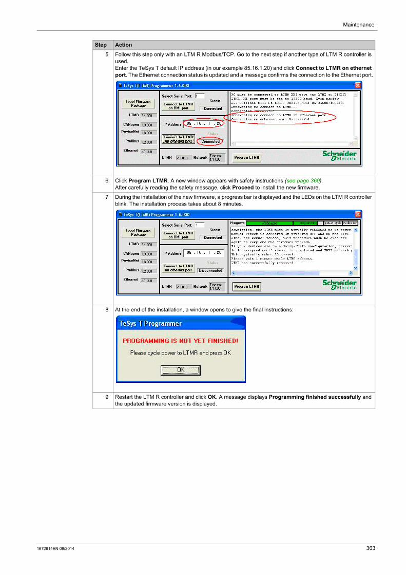
Maintenance
5 Follow this step only with an LTM R Modbus/TCP. Go to the next step if another type of LTM R controller is used.Enter the TeSys T default IP address (in our example 85.16.1.20) and click Connect to LTMR on ethernet port. The Ethernet connection status is updated and a message confirms the connection to the Ethernet port.
6 Click Program LTMR. A new window appears with safety instructions (see page 360).After carefully reading the safety message, click Proceed to install the new firmware.
7 During the installation of the new firmware, a progress bar is displayed and the LEDs on the LTM R controller blink. The installation process takes about 8 minutes.
8 At the end of the installation, a window opens to give the final instructions:
9 Restart the LTM R controller and click OK. A message displays Programming finished successfully and the updated firmware version is displayed.
Step Action
1672614EN 09/2014 363

Maintenance
Self Test with Motor On
Description
Use the self test command to check the internal operation of both the LTM R controller and the LTM E expansion module. The self test command can be performed from the Device menu in the connected mode (see page 29).
When the motor is On, performing a self test simulates a thermal fault to check if the logic output O.4 is working correctly. It triggers a thermal overload fault.
During a self test, the LTM R controller sets the self test command parameter to 1. When the self test finishes, this parameter is reset to 0.
364 1672614EN 09/2014
TeSys T DTM for FDT Container
Connection to the LTM R Controller
1672614EN 09/2014
Connection to the LTM R Controller
Chapter 11Connection to the LTM R Controller
Overview
This chapter describes how to physically connect the PC running SoMove with the TeSys T DTM to the LTM R controller, including connection accessories that are used. It also describes how to connect the PC running the TeSys T (LTMR) Programmer to the LTM R Controller to update its firmware.
What Is in This Chapter?
This chapter contains the following topics:
Topic Page
Hardware Connection for SoMove 366
Hardware Connection for the Firmware Update 368
1672614EN 09/2014 365

Connection to the LTM R Controller
Hardware Connection for SoMove
Overview
This section describes how to physically connect the LTM R controller to a PC running SoMove with the TeSys T DTM.
The PC requires its own power source and must be connected to the RJ45 port on the LTM R controller or the HMI interface port (RJ45) on the LTM E expansion module when attached to the LTM R controller.
The PC can be connected in a 1-to-1 configuration to a single LTM R controller, or in a 1-to-many configuration to multiple controllers.
Connecting to a PC Running SoMove with the TeSys T DTM in 1-to-1 Mode
The diagrams below show a 1-to-1 connection from a PC running SoMove with the TeSys T DTM to the LTM R controller, with and without the LTM E expansion module and the LTM CU control operator unit:
1 PC running SoMove with the TeSys T DTM2 Cable kit TCSMCNAM3M002P3 LTM R controller4 LTM E expansion module5 LTM CU control operator unit6 Grounding collar7 HMI device connection cable LTM9CU••
366 1672614EN 09/2014
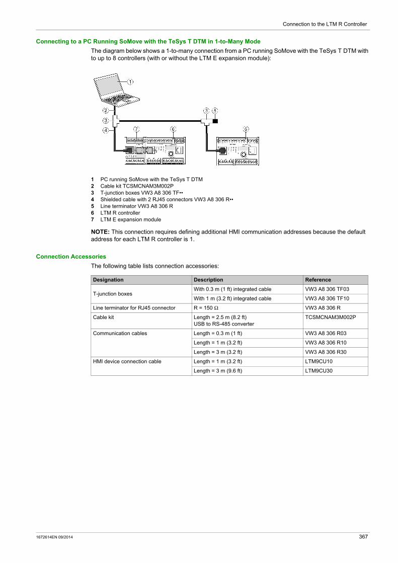
Connection to the LTM R Controller
Connecting to a PC Running SoMove with the TeSys T DTM in 1-to-Many Mode
The diagram below shows a 1-to-many connection from a PC running SoMove with the TeSys T DTM with to up to 8 controllers (with or without the LTM E expansion module):
1 PC running SoMove with the TeSys T DTM2 Cable kit TCSMCNAM3M002P3 T-junction boxes VW3 A8 306 TF••4 Shielded cable with 2 RJ45 connectors VW3 A8 306 R••5 Line terminator VW3 A8 306 R6 LTM R controller7 LTM E expansion module
NOTE: This connection requires defining additional HMI communication addresses because the default address for each LTM R controller is 1.
Connection Accessories
The following table lists connection accessories:
Designation Description Reference
T-junction boxesWith 0.3 m (1 ft) integrated cable VW3 A8 306 TF03
With 1 m (3.2 ft) integrated cable VW3 A8 306 TF10
Line terminator for RJ45 connector R = 150 Ω VW3 A8 306 R
Cable kit Length = 2.5 m (8.2 ft)USB to RS-485 converter
TCSMCNAM3M002P
Communication cables Length = 0.3 m (1 ft) VW3 A8 306 R03
Length = 1 m (3.2 ft) VW3 A8 306 R10
Length = 3 m (3.2 ft) VW3 A8 306 R30
HMI device connection cable Length = 1 m (3.2 ft) LTM9CU10
Length = 3 m (9.6 ft) LTM9CU30
1672614EN 09/2014 367
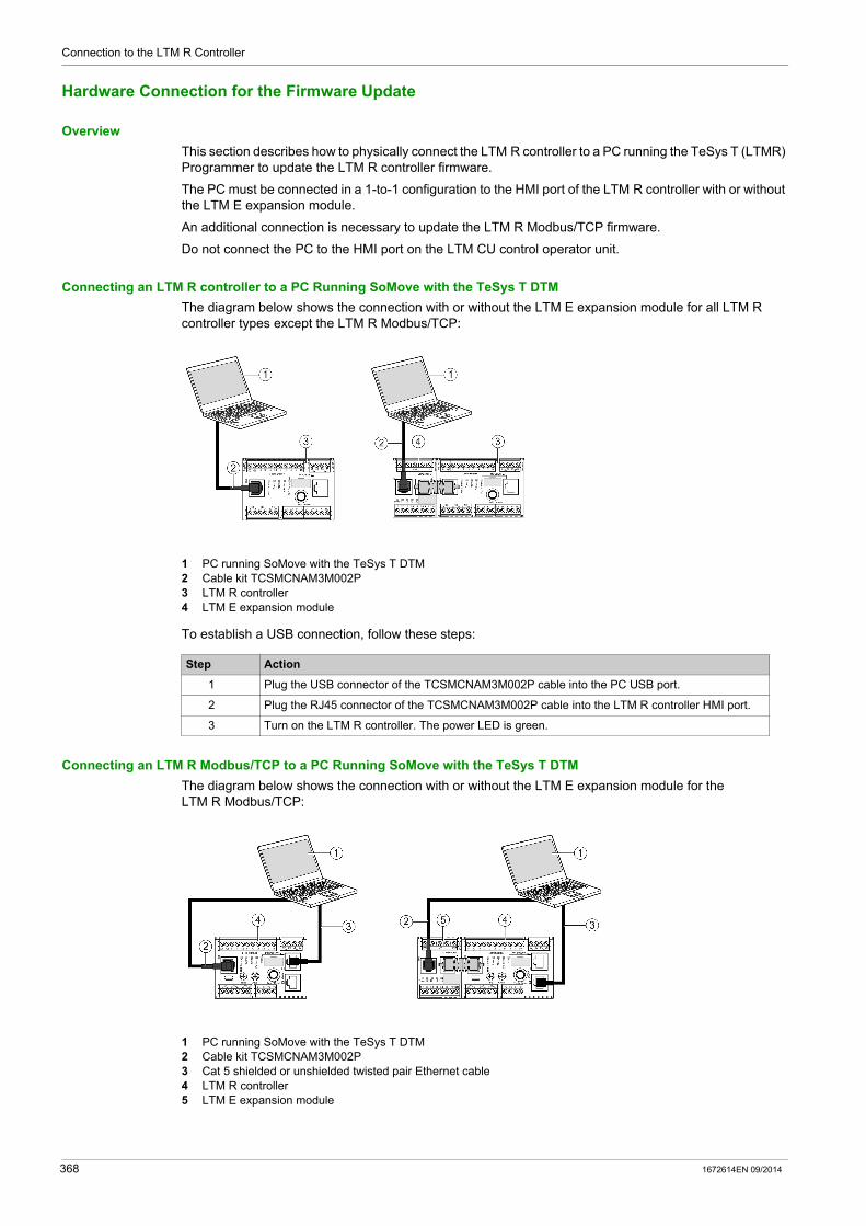
Connection to the LTM R Controller
Hardware Connection for the Firmware Update
Overview
This section describes how to physically connect the LTM R controller to a PC running the TeSys T (LTMR) Programmer to update the LTM R controller firmware.
The PC must be connected in a 1-to-1 configuration to the HMI port of the LTM R controller with or without the LTM E expansion module.
An additional connection is necessary to update the LTM R Modbus/TCP firmware.
Do not connect the PC to the HMI port on the LTM CU control operator unit.
Connecting an LTM R controller to a PC Running SoMove with the TeSys T DTM
The diagram below shows the connection with or without the LTM E expansion module for all LTM R controller types except the LTM R Modbus/TCP:
1 PC running SoMove with the TeSys T DTM2 Cable kit TCSMCNAM3M002P3 LTM R controller4 LTM E expansion module
To establish a USB connection, follow these steps:
Connecting an LTM R Modbus/TCP to a PC Running SoMove with the TeSys T DTM
The diagram below shows the connection with or without the LTM E expansion module for the LTM R Modbus/TCP:
1 PC running SoMove with the TeSys T DTM2 Cable kit TCSMCNAM3M002P3 Cat 5 shielded or unshielded twisted pair Ethernet cable4 LTM R controller5 LTM E expansion module
Step Action
1 Plug the USB connector of the TCSMCNAM3M002P cable into the PC USB port.
2 Plug the RJ45 connector of the TCSMCNAM3M002P cable into the LTM R controller HMI port.
3 Turn on the LTM R controller. The power LED is green.
368 1672614EN 09/2014
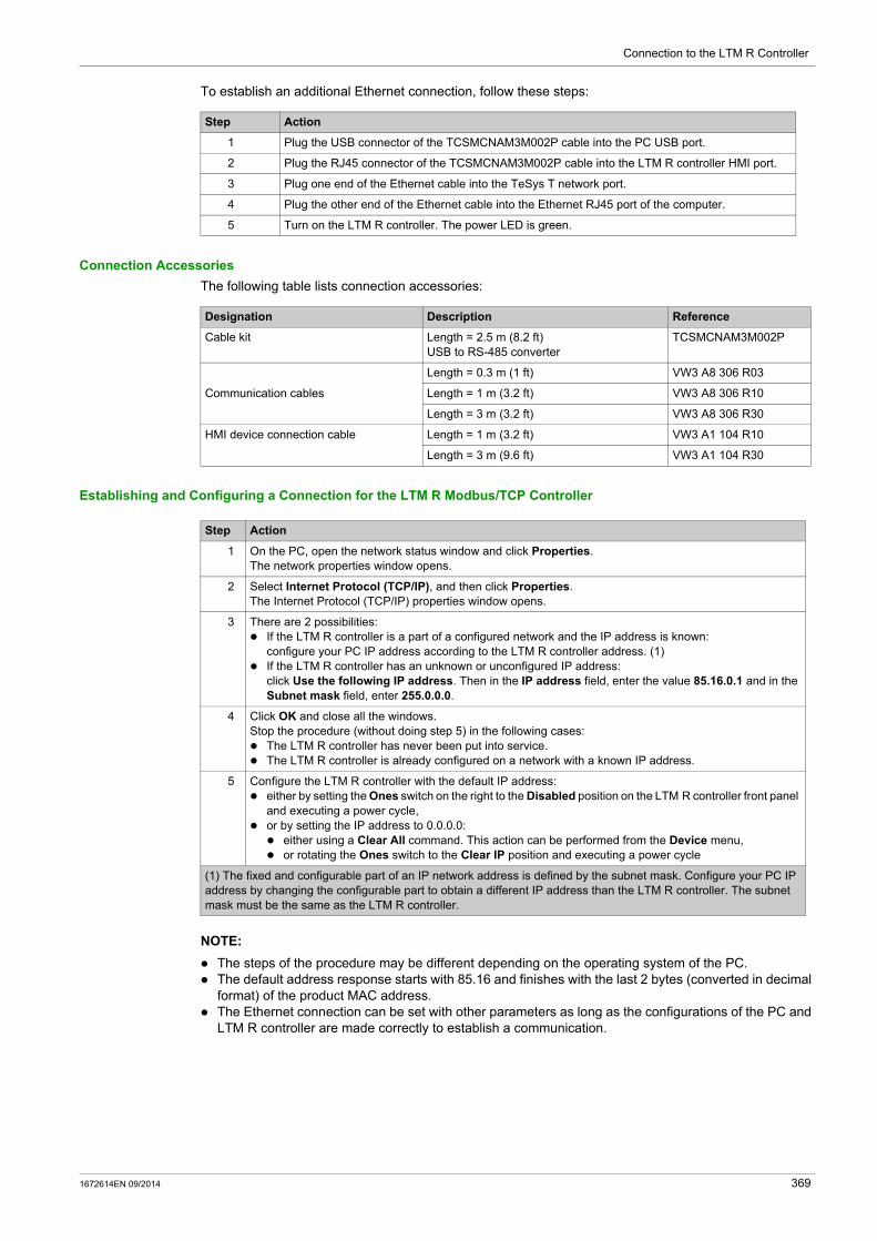
Connection to the LTM R Controller
To establish an additional Ethernet connection, follow these steps:
Connection Accessories
The following table lists connection accessories:
Establishing and Configuring a Connection for the LTM R Modbus/TCP Controller
NOTE:
The steps of the procedure may be different depending on the operating system of the PC. The default address response starts with 85.16 and finishes with the last 2 bytes (converted in decimal
format) of the product MAC address. The Ethernet connection can be set with other parameters as long as the configurations of the PC and
LTM R controller are made correctly to establish a communication.
Step Action
1 Plug the USB connector of the TCSMCNAM3M002P cable into the PC USB port.
2 Plug the RJ45 connector of the TCSMCNAM3M002P cable into the LTM R controller HMI port.
3 Plug one end of the Ethernet cable into the TeSys T network port.
4 Plug the other end of the Ethernet cable into the Ethernet RJ45 port of the computer.
5 Turn on the LTM R controller. The power LED is green.
Designation Description Reference
Cable kit Length = 2.5 m (8.2 ft)USB to RS-485 converter
TCSMCNAM3M002P
Communication cables
Length = 0.3 m (1 ft) VW3 A8 306 R03
Length = 1 m (3.2 ft) VW3 A8 306 R10
Length = 3 m (3.2 ft) VW3 A8 306 R30
HMI device connection cable Length = 1 m (3.2 ft) VW3 A1 104 R10
Length = 3 m (9.6 ft) VW3 A1 104 R30
Step Action
1 On the PC, open the network status window and click Properties.The network properties window opens.
2 Select Internet Protocol (TCP/IP), and then click Properties.The Internet Protocol (TCP/IP) properties window opens.
3 There are 2 possibilities: If the LTM R controller is a part of a configured network and the IP address is known:
configure your PC IP address according to the LTM R controller address. (1) If the LTM R controller has an unknown or unconfigured IP address:
click Use the following IP address. Then in the IP address field, enter the value 85.16.0.1 and in the Subnet mask field, enter 255.0.0.0.
4 Click OK and close all the windows.Stop the procedure (without doing step 5) in the following cases: The LTM R controller has never been put into service. The LTM R controller is already configured on a network with a known IP address.
5 Configure the LTM R controller with the default IP address: either by setting the Ones switch on the right to the Disabled position on the LTM R controller front panel
and executing a power cycle, or by setting the IP address to 0.0.0.0: either using a Clear All command. This action can be performed from the Device menu, or rotating the Ones switch to the Clear IP position and executing a power cycle
(1) The fixed and configurable part of an IP network address is defined by the subnet mask. Configure your PC IP address by changing the configurable part to obtain a different IP address than the LTM R controller. The subnet mask must be the same as the LTM R controller.
1672614EN 09/2014 369
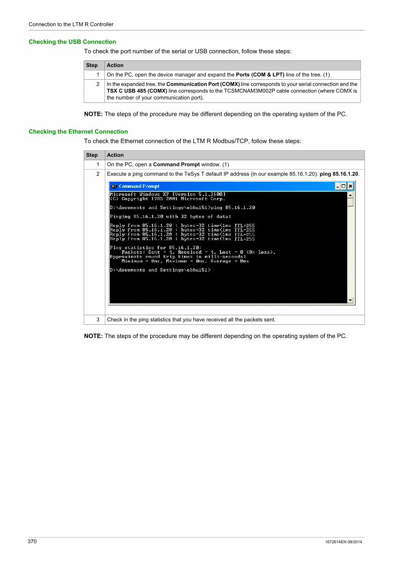
Connection to the LTM R Controller
Checking the USB Connection
To check the port number of the serial or USB connection, follow these steps:
NOTE: The steps of the procedure may be different depending on the operating system of the PC.
Checking the Ethernet Connection
To check the Ethernet connection of the LTM R Modbus/TCP, follow these steps:
NOTE: The steps of the procedure may be different depending on the operating system of the PC.
Step Action
1 On the PC, open the device manager and expand the Ports (COM & LPT) line of the tree. (1)
2 In the expanded tree, the Communication Port (COMX) line corresponds to your serial connection and the TSX C USB 485 (COMX) line corresponds to the TCSMCNAM3M002P cable connection (where COMX is the number of your communication port).
Step Action
1 On the PC, open a Command Prompt window. (1)
2 Execute a ping command to the TeSys T default IP address (in our example 85.16.1.20): ping 85.16.1.20.
3 Check in the ping statistics that you have received all the packets sent.
370 1672614EN 09/2014

TeSys T DTM for FDT Container
Index
1672614EN 09/2014
Index
AAccumulator, 283active power, 62, 63, 89
consumption, 64Addition
Addition FBD Function Block, 325AND
AND FBD Function Block, 334AND_BIT, 293AND_K, 303AND_NOT_BIT, 294AND_NOT_NV_BIT, 295AND_NOT_TMP_BIT, 295AND_NV_BIT, 294AND_NV_REG, 304AND_REG, 303AND_TMP_BIT, 294AND_TMP_REG, 303apparent power, 62Argument, 281auto restart
delayed timeout, 159immediate timeout, 159
auto-resetattempts group 1 setting, 212attempts group 2 setting, 212attempts group 3 setting, 212count, 83group 1 timeout, 212group 2 timeout, 212group 3 timeout, 212
automatic restart, 159average current ratio, 89average voltage, 61, 89
Bbaud rate, 224, 225, 226
CCALL_EOM, 290CANopen
baud rate, 225node address, 225
commandclear all, 67, 218clear controller settings, 218clear network port settings, 219clear statistics, 80, 218clear thermal capacity level, 108, 211, 218FDR data backup, 249FDR data restore, 249motor low speed, 201motor run forward, 191, 193, 196, 201motor run reverse, 193, 196, 201statistics, 67
Comments, 281communication loss, 73
1672614EN 09/2014
COMP_K_REG, 301COMP_NV_REG, 302COMP_REG, 302COMP_TMP_REG, 302Compare
Compare FBD Function Block, 325Compiling, 350Computation Blocks, 325configurable settings, 104configuration checksum, 72configuration file, 205Connected, 355Constant Bit
Constant Bit FBD Function Block, 327Constant Word
Constant Word FBD Function Block, 327control
direct transition, 195, 201principles, 185
control channels, 174, 175HMI, 175network, 176selecting, 175terminal strip, 175
control circuit2-wire, 1863-wire, 186
control transfer mode, 176control wiring, 186controller
internal fault, 66internal faults count, 88internal temperature, 67internal temperature max, 67internal temperature warning enable, 67
COUNTER, 312Counter
Counter FBD Function Block, 331counter
Ethernet MB error messages sent, 255Ethernet MB messages received, 255Ethernet MB messages sent, 255Ethernet open clients, 255Ethernet opened servers, 255Ethernet received correct frames, 254Ethernet transmitted correct frames, 254
Counter NVCounter NV FBD Function Block, 331
COUNTER_NV, 313counters
communication loss, 87internal faults, 88
currentaverage, 54
371

Index
current phase imbalance, 55, 89, 126fault enable, 127fault threshold, 127fault timeout running, 127fault timeout starting, 127faults count, 84warning enable, 127warning threshold, 127
current phase loss, 129fault enable, 130faults count, 84timeout, 130warning enable, 130
current phase reversal, 131fault enable, 131faults count, 84phase sequence, 131
current ratioaverage, 54L1, 51L2, 51L3, 51
Custom logic editorBoolean logic commands, 283Commands, 283Counter logic commands, 287Latch logic commands, 287Math logic commands, 288Register logic commands, 285Timer logic commands, 287
custom operating mode, 205customized program, 260, 260
Ddata transfer, 265date and time, 89DeviceNet
baud rate, 226node address, 226
diagnosticfault, 85fault enable, 68faults count, 85warning enables, 68
diagnostic faultswiring faults, 70
diagnosticsEthernet, 252
DisplayOptions, 346
DivisionDivision FBD Function Block, 326
EError, 352
372
Ethernetbasic HW diag validity, 252device name, 255diagnostics, 252frame status, 254gateway, 253gateway address setting, 227, 255global status, 253IP address, 253IP address setting, 227, 255IP assignment capability, 255IP assignment operational, 256MAC address, 254master IP address setting, 237MB error messages sent counter, 255MB messages received counter, 255MB messages sent counter, 255opened clients counter, 255opened servers counter, 255received correct frames counter, 254services status, 253services validity, 253SNMP community name get setting, 258SNMP community name set setting, 258SNMP community name trap setting, 258SNMP manager address 1 setting, 258SNMP manager address 2 setting, 258SNMP system contact setting, 258SNMP system location setting, 258SNMP system name setting, 258subnet mask, 253subnet mask setting, 227, 255transmitted correct frames counter, 254
external ground current, 143fault threshold, 144fault timeout, 144warning threshold, 144
Ffallback
control transition, 177fallback condition, 74fault
reset timeout, 110fault code, 89, 216, 217fault counters
protection, 84fault management, 206
introduction, 207fault reset mode
automatic, 211manual, 209remote, 214
fault statistics, 79history, 89
faults count, 81faulty device replacement (FDR), 246FBD
Resource management, 341
1672614EN 09/2014

Index
FBD BlocksDeleting, 344Duplicating, 344Inserting, 338Linking, 339Properties, 340Selecting, 343
FBD Blocks Properties, 340FBD editor
Creating an FBD file, 322Using the FBD language, 322
FBD ElementsComputation Blocks, 325Function Blocks, 330Inputs Blocks, 327Logic Blocks, 334Outputs Blocks, 335
FBD language, 321FDR (faulty device replacement), 246FLC, 181, 201FLC1, 201FLC2, 201frequency, 58, 89full load current max, 89Function Block Diagram, 321Function Blocks, 330
Gground CT
primary, 52, 143secondary, 52, 143
ground current, 52, 140fault enable, 140faults count, 84ground fault disabled, 140mode, 52, 140, 141, 143ratio, 52warning enable, 140
ground current ratio, 89
Hhigh priority registers
mirroring, 238HMI display temperature sensor degree CF, 57HMI keys
independent operating mode, 192overload operating mode, 190reverser operating mode, 195two-speed operating mode, 204two-step operating mode, 200
HMI portaddress setting, 229baud rate setting, 229comm loss timeout, 229fallback setting, 229faults count, 87parity setting, 229
hysteresis, 105
II/O scanning
configuring, 238
1672614EN 09/2014
Initialization, 355Inputs Blocks, 327Inserting FBD Blocks, 338internal ground current, 141
fault threshold, 142fault timeout, 142warning threshold, 142
internal portfaults count, 88
IP addressing, 241
Jjam, 134
fault enable, 134fault threshold, 134fault timeout, 134faults count, 84warning enable, 134warning threshold, 134
LL1 current highest imbalance, 126L1 current ratio, 89L1-L2 highest imbalance, 146L1-L2 voltage, 89L2 current highest imbalance, 126L2 current ratio, 89L2-L3 highest imbalance, 146L2-L3 voltage, 89L3 current highest imbalance, 126L3 current ratio, 89L3-L1 highest imbalance, 146L3-L1 voltage, 89LATCH, 311LATCH_NV, 311line currents, 51link
ethernet, 240Linking FBD Blocks, 339load shedding, 157
timeout, 157load sheddings count, 93LOAD_BIT, 291LOAD_K_BIT, 291LOAD_K_REG, 300LOAD_NOT_BIT, 292LOAD_NOT_NV_BIT, 293LOAD_NOT_TMP_BIT, 293LOAD_NV_BIT, 292LOAD_NV_REG, 301LOAD_REG, 300LOAD_TMP_BIT, 292LOAD_TMP_REG, 301Logic Blocks, 334Logic command
Text view, 281Logic Commands, 283
373
Index
logic commandsAND_BIT, 293AND_K, 303AND_NOT_BIT, 294AND_NOT_NV_BIT, 295AND_NOT_TMP_BIT, 295AND_NV_BIT, 294AND_NV_REG, 304AND_REG, 303AND_TMP_BIT, 294AND_TMP_REG, 303CALL_EOM, 290COMP_K_REG, 301COMP_NV_REG, 302COMP_REG, 302COMP_TMP_REG, 302COUNTER, 312COUNTER_NV, 313LATCH, 311LATCH_NV, 311LOAD_BIT, 291LOAD_K_BIT, 291LOAD_K_REG, 300LOAD_NOT_BIT, 292LOAD_NOT_NV_BIT, 293LOAD_NOT_TMP_BIT, 293LOAD_NV_BIT, 292LOAD_NV_REG, 301LOAD_REG, 300LOAD_TMP_BIT, 292LOAD_TMP_REG, 301LOGIC_ID, 290NOP, 290ON_ADD, 314ON_DIV, 315ON_MUL, 315ON_SET_NV_REG, 307ON_SET_REG, 307ON_SET_TMP_REG, 307ON_SUB, 314OR_BIT, 295OR_K, 304OR_NOT_BIT, 296OR_NOT_NV_BIT, 297OR_NOT_TMP_BIT, 297OR_NV_BIT, 296OR_NV_REG, 305OR_REG, 304OR_TMP_BIT, 296OR_TMP_REG, 305SET_BIT, 297SET_NOT_BIT, 298SET_NOT_NV_BIT, 299SET_NOT_TMP_BIT, 298SET_NV_BIT, 298SET_TMP_BIT, 298TIMER_K_SEC, 309TIMER_K_TENTHS, 310TIMER_SEC, 308TIMER_TENTHS, 309XOR_K, 305XOR_NV_REG, 306XOR_REG, 306XOR_TMP_REG, 306
logic file, 205
374
logic input behavior, 186independent operating mode, 192overload operating mode, 190reverser operating mode, 195two-speed operating mode, 203two-step operating mode, 199
logic output behavior, 187independent operating mode, 192overload operating mode, 190reverser operating mode, 195two-speed operating mode, 204two-step operating mode, 200
Logic Primitive window, 354Logic Simulator, 353LOGIC_ID, 290long start, 132
fault enable, 132fault threshold, 132, 181fault timeout, 113, 132, 181faults count, 84
MMAC-ID, 226master IP, 237memory
logic memory characteristics, 265metering and monitoring functions, 49mirroring high priority registers, 238Modbus
master IP, 237motor
auxiliary fan cooled, 107, 110full load current ratio, 89, 110, 113, 201full load power, 164, 166high speed full load current ratio, 110, 113, 201last start current ratio, 95last start duration, 96LO1 starts count, 91LO2 starts count, 91nominal voltage, 152, 154phases, 70phases sequence, 151predefined operating mode, 186starts count, 91starts per hour count, 92step 1 to 2 threshold, 196step 1 to 2 timeout, 196transition timeout, 195, 196, 201trip class, 110
motor control functions, 173motor history, 90
last start max current, 95last start time, 96motor operating time, 97motor starts, 91motor starts per hour, 92
motor operating modeindependent, 186overload, 186reverser, 186two-speed, 186two-step, 186
motor phases sequence, 131
1672614EN 09/2014

Index
motor predefined operating modeindependent, 191overload, 189reverser, 193two-speed, 201two-step, 196
motor protection functions, 104current phase imbalance, 126current phase loss, 129current phase reversal, 131external ground current, 143ground current, 140internal ground current, 141jam, 134long start, 132motor temperature sensor, 114motor temperature sensor-NTC analog, 121motor temperature sensor-PT100, 117motor temperature sensor-PTC analog, 119motor temperature sensor-PTC binary, 115operation, 104over power factor, 170overcurrent, 138overpower, 166overvoltage, 154thermal overload, 107thermal overload - definite time, 112thermal overload - inverse thermal, 108under power factor, 168undercurrent, 136underpower, 164undervoltage, 152voltage phase imbalance, 146voltage phase loss, 149voltage phase reversal, 151
motor running, 99motor starting, 99motor temperature sensor, 89, 114
display degree CF, 118fault enable, 114fault threshold, 119, 121fault threshold degree, 118faults count, 84PT100, 117type, 70, 114, 115, 119, 121warning, 114warning threshold, 119, 121warning threshold degree, 118
MultiplexerMultiplexer FBD Function Block, 332
MultiplicationMultiplication FBD Function Block, 326
1672614EN 09/2014
Nnetwork port
address setting, 223baud rate setting, 223comm loss timeout, 223, 228, 237, 240config faults count, 87endian setting, 223fallback setting, 223, 228, 237fault enable, 228faults count, 87FDR auto backup enable, 249FDR auto backup period setting, 249FDR controller interval, 228FDR status, 249, 250FDR synchro setting, 228frame type, 227, 254internal faults count, 87parity setting, 223SNMP trap authentication failure enable, 258warning enable, 228
node-ID, 224, 225Non Volatile Latch
Non Volatile Latch FBD Function Block, 332NOP, 290NOT
NOT FBD Function Block, 334NTC analog, 121
Oon level current, 181ON_ADD, 314ON_DIV, 315ON_MUL, 315ON_SET_NV_REG, 307ON_SET_REG, 307ON_SET_TMP_REG, 307ON_SUB, 314operating modes, 184
custom, 205independent, 191introduction, 186overload, 189reverser, 193two speed, 201two-step, 196
operating states, 174, 178chart, 179not ready, 178protection functions, 179ready, 178run, 178start, 178
operating time, 97OR
OR FBD Function Block, 334OR_BIT, 295OR_K, 304OR_NOT_BIT, 296OR_NOT_NV_BIT, 297OR_NOT_TMP_BIT, 297OR_NV_BIT, 296OR_NV_REG, 305OR_REG, 304
375
Index
OR_TMP_BIT, 296OR_TMP_REG, 305Outputs Blocks, 335over power factor, 170
fault enable, 170fault threshold, 170fault timeout, 170faults count, 84warning enable, 170warning threshold, 170
overcurrent, 138fault enable, 138fault threshold, 138fault timeout, 138faults count, 84warning enable, 138warning threshold, 138
overpower, 166fault enable, 166fault threshold, 166fault timeout, 166faults count, 84warning enable, 166warning threshold, 166
overvoltage, 154fault enable, 155fault threshold, 155fault timeout, 155faults count, 84warning enable, 155warning threshold, 155
PPCode, 351power factor, 62, 89predefined operating modes
control wiring and fault management, 188PROFIBUS DP
baud rate, 224node address, 224
Program validity, 358protection functions, 103
communication, 208configuration, 179, 208current, 125, 180, 208customized, 103diagnostic, 179, 208faults, 103internal, 179, 208motor temperature sensor, 180, 208operating states, 179power, 163, 180, 208thermal , 106thermal overload, 180, 208voltage, 145, 180, 208warnings, 103wiring, 179, 208
PT100, 117PTC analog, 119PTC binary, 115
376
Rrapid cycle
lockout, 123lockout timeout, 123
reactive power, 63consumption, 64
registernon-volatile register, 266register 1200, 267register 1201, 268register 1202, 268register 1203, 268register 1204, 268register 1205, 268registers 1301...1399, 268temporary register, 266
Register 1200, 354Register 457, 354Register 458, 354Register Bit In
Register Bit In FBD Function Block, 328Register Bit Out
Register Bit Out FBD Function Block, 335Register NV Bit In
Register NV Bit In FBD Function Block, 328Register NV Bit Out
Register NV Bit Out FBD Function Block, 336Register NV Word In
Register NV Word In FBD Function Block, 328Register NV Word Out
Register NV Word Out FBD Function Block, 336Register Temp Bit In
Register Temp Bit In FBD Function Block, 329Register Temp Bit Out
Register Temp Bit Out FBD Function Block, 336Register View, 354Register Word In
Register Word In FBD Function Block, 328Register Word Out
Register Word Out FBD Function Block, 335Resource management, 341
SSaving, 282Selecting FBD Blocks, 343SET_BIT, 297SET_NOT_BIT, 298SET_NOT_NV_BIT, 299SET_NOT_TMP_BIT, 298SET_NV_BIT, 298SET_TMP_BIT, 298simple network management protocol (SNMP), 257Simulator, 353SNMP (simple network management protocol), 257Start a Trace, 354start cycle, 181Structured text editor
Editing a structured text file, 279Using the structured text editor, 279
Structured text program, 278Subtraction
Subtraction FBD Function Block, 326
1672614EN 09/2014
Index
system and device monitoringfaults, 65
system and device monitoring faultscontrol command diagnostic errors, 68
system operating status, 98minimum wait time, 100motor state, 99
system ready, 99
TTemp Word In
Temp Word In FBD Function Block, 329Temp Word Out
Temp Word Out FBD Function Block, 336TeSys T
motor management system, 17thermal capacity level, 56, 89, 108, 110thermal overload, 107
definite time, 112fault, 110fault definite timeout, 113fault enable, 107fault reset mode, 207fault reset threshold, 110, 207fault reset timeout, 207faults count, 84, 110, 112inverse thermal, 108mode, 107time to trip, 75warning, 110warning enable, 107warning threshold, 110, 113warnings count, 84, 110, 112
time to trip, 75Timer Seconds
Timer Seconds FBD Function Block, 332Timer TenthSeconds
Timer TenthSeconds FBD Function Blocks, 333TIMER_K_SEC, 309TIMER_K_TENTHS, 310TIMER_SEC, 308TIMER_TENTHS, 309Toolbox
Computation Blocks, 325Function Blocks, 330Inputs Blocks, 327Logic Blocks, 334Outputs Blocks, 335
TransferringDevice custom logic to PC, 356Execution, 358Logic files, 356
Uunder power factor, 168
fault enable, 168fault threshold, 168fault timeout, 168faults count, 84warning enable, 168warning threshold, 168
1672614EN 09/2014
undercurrent, 136fault enable, 136fault threshold, 136fault timeout, 136faults count, 84warning enable, 136warning threshold, 136
underpower, 164fault enable, 164fault threshold, 164fault timeout, 164faults count, 84warning enable, 164warning threshold, 164
undervoltage, 152fault enable, 153fault threshold, 153fault timeout, 153faults count, 84warning enable, 153warning threshold, 153
user map addresses setting, 231user map values, 231
Vvariables
custom logic variables, 266LTM R variables, 267
View window, 354Volatile Latch
Volatile Latch FBD Function Block, 331voltage
average, 61L1-L2, 59L2-L3, 59L3-L1, 59
voltage diprestart threshold, 157, 159restart timeout, 157, 159threshold, 157, 159
voltage dip mode, 159voltage imbalance, 60voltage mode, 157voltage phase imbalance, 60, 89, 146
fault enable, 147fault threshold, 147fault timeout running, 147fault timeout starting, 147faults count, 84warning enable, 147warning threshold, 147
voltage phase loss, 149fault enable, 150fault timeout, 150faults count, 84warning enable, 150
voltage phase reversal, 151fault enable, 151faults count, 84, 131, 151
Wwarning counters
protection, 84
377

Index
warnings count, 82, 84wiring
fault, 70fault enable, 70faults count, 86
WorkspaceAppearance options, 347Graph options, 347Options, 346
XXOR_K, 305XOR_NV_REG, 306XOR_REG, 306XOR_TMP_REG, 306
378
1672614EN 09/2014