MOLDED-CASE CIRCUIT BREAKERS & EARTH-LEAKAGE ...
135
MOLDED-CASE CIRCUIT BREAKERS & EARTH-LEAKAGE CIRCUIT BREAKERS 301600A FRAME ADVANCED AND EVER ADVANCING Mitsubishi Electric Corporation's Fukuyama Works, which produces these products, is certified as meeting the ISO14001 environmental management system standard. ISO 9001 NATIONAL ACCREDITATION OF CERTIFICATION BODIES 00 A
-
Upload
khangminh22 -
Category
Documents
-
view
0 -
download
0
Transcript of MOLDED-CASE CIRCUIT BREAKERS & EARTH-LEAKAGE ...

MOLDED-CASE CIRCUIT BREAKERS & EARTH-LEAKAGE CIRCUIT BREAKERS 30�1600A FRAME
ADVANCED AND EVER ADVANCING
Mitsubishi Electric Corporation's Fukuyama Works,which produces these products, is certified as meetingthe ISO14001 environmental management system standard.
ISO 9001
NATIONALACCREDITATION
OF CERTIFICATIONBODIES 00
A

CONTENTSCONTENTS
C o n t e n t s
I n t r o d u c t i o n
R a p i d P r o g r e s s
D e v e l o p m e n t
E v o l u t i o n
S u p e r i o r i t y
M o d e l N a m i n g
S e r i e s O u t l i n e
S e r i e s R a t i n g s
2~ 3
4~ 5
6~ 7
8
9
10
11
12
13
14~ 15
16~ 23
24~ 25
26~ 27
28~ 31
32~ 35
36
37
38~ 39
40
41
42
43
S p e c i f i c a t i o n s
M o l d e d - c a s e c i r c u i t b r e a k e r s
M C C B N F - C
M C C B N F - S
M C C B N F - U
E a r t h - l e a k a g e c i r c u i t b r e a k e r s
E L C B N V - C
E L C B N V - S
M i n i a t u r e c i r c u i t b r e a k e r s
B H
M o t o r P r o t e c t i o n
M C C B M B
E L C B M N
O t h e r s
E L R & Z C T
C i r c u i t P r o t e c t o r C P
S p e c i a l P u r p o s e B r e a k e r s
M a g O n l y, D C - U s e a n d D S N - T y p e
4 0 0 H z - U s e, L o w - I n s t a n t a n e o u s a n d
G e n e r a t o r - P r o t e c t i o n
C o n n e c t i o n
T y p e s a n d A c c e s s o r i e s
2

CONTENTSCONTENTS
O r d e r i n g I n f o r m a t i o n
Safety tip:Be sure to read the instruction manual thoroughly before using these products.
A c c e s s o r i e s
I n t e r n a l A c c e s s o r i e s
C a s s e t t e - T y p e, B u i l t - I n
M C C B M a x i m u m n u m b e r o f a c c e s s o r i e s
E L C B M a x i m u m n u m b e r o f a c c e s s o r i e s
N e w p r o d u c t s, o p t i o n s, e t c .
E x t e r n a l A c c e s s o r i e s
E l e c t r i c a l l y o p e r a t e d
M e c h a n i c a l i n t e r l o c k s
O p e r a t i n g h a n d l e s
T e r m i n a l c o v e r s
4 4
4 5 ~ 4 6
4 7 ~ 4 9
5 0 ~ 5 5
5 6 ~ 5 9
6 0 ~ 6 2
6 3 ~ 6 7
6 8 ~ 6 9
C h a r a c t e r i s t i c s
M C C B
E L C B
B H
C P
D i m e n s i o n s
M C C B
E L C B
B H
C o m p a r i s o n b e t w e e n N e w a n d F o r m e r M o d e l s
C o m p a t i b i l i t y
O t h e r c h a n g e s
D i m e n s i o n s
1 3 4
7 0 ~ 8 5
8 6 ~ 9 4
9 5 ~ 9 6
9 7
9 8 ~ 1 1 2
1 1 3 ~ 1 1 8
1 1 9
1 2 0 ~ 1 2 2
1 2 3 ~ 1 2 7
1 2 8 ~ 1 3 3
3

As the leading manufacturer of circuit breakers, Mitsubishi Electric has long developed products to fit the needs of the era.
With the completion of the Progressive Super Series (PSS) circuit breakers covering 400~800 Ampere frame(AF), we can now offer a full complement of PSS models from 30~800AF. With our advanced
technology and know-how, we’re already anticipating the needs of the next era by producing new circuit breakers for the
21st century: PSS circuit breakers.
Circuit Breakers for the 21st CenturyThe completion of a full line-up of PSS breakers
Mitsubishi Electric is pioneering new technology that will take us into the 21st century. One such technology is the new digital display unit for circuit condition. In keeping with the era’s needs, it per-mits energy management. As such, it can be justly described as a circuit breaker with a brain, a new type of intelligent breaker for the next century.
The new circuit breakers are easier to use than ever before. The module types have been simpli-fied to just two sizes, allowing easier board design standardization and rationalization. The cassette accessories also make replacement a simple, one-touch operation.
To reflect a variety of uses and applications, the line-up has been further expanded. This new com-prehensive line-up answers the demands of the era for models with high specifications for a range of purposes and applications.
The new digital Electronic Trip Relay (ETR), the brain of the circuit breaker, ensures accurate pro-tection of the circuit. Using advanced digital tech-nology, Mitsubishi has succeeded in creating a new type of electronic circuit breaker, and realized a new level of safety and reliability.
RAPID PROGRESS21st century functions
DEVELOPMENTEase of use
EVOLUTIONTechnology
SUPERIORITYBreaker with a brain
4

Progressive Super Series
Technology continues to evolve toward the 21st century. The consumption of electric power increases as well, demanding from
circuit breakers new levels of functionality, flexibility, power- and space-saving. To answer the requirements of the era, we have realized a new level of harmony between breaker and measuring component.
We have created a new generation of breakers, which are without equal to any previously produced models. Mitsubishi Electric is proud
to announce the newest evolution in circuit breakers for the 21st century, combining new levels of superiority and reliability.
Full Scale Progressive Super Series
Packed with Mitsubishi’s 21st century technology.Circuit breakers with advanced intelligence are now available.
Progressive Super Series
Caution: Before installing these circuit breakers, it is recommended that their safe and correct usage be studied with a thorough reading of the “Handling and Maintenance” guidebook.
5

Display
The circuit breaker incorporates a digital Measuring Display Unit (MDU). It can measure and display a range of circuit condition data for more efficient energy management.
Measuring and displaying the load current, line voltage, electric power, electric energy, harmonic current (3rd, 5th, 7th and total) enables energy control.
MonitoringThe LED lights when it monitors the following alarm output from the circuit breaker.
•PAL: Pre-alarm
•OVER: Overload alarm
Load currentPresent value, demand value, maximum demand valueLine voltagePresent value, demand value, maximum demand valueHarmonic current (3rd, 5th, 7th and total)Present value, demand value, maximum demand valueElectric powerPresent value, demand value, maximum demand valueElectric energyElectric energy, electric energy (hourly value) maximum electric energy (hourly value)
Power factorPresent value
Measuring display item 400AF 630AF 800AF
6
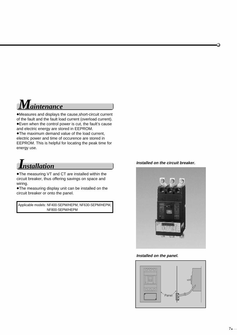
Maintenance•Measures and displays the cause,short-circuit current of the fault and the fault load current (overload current).
•Even when the control power is cut, the fault’s cause and electric energy are stored in EEPROM.
•The maximum demand value of the load current, electric power and time of occurence are stored in EEPROM. This is helpful for locating the peak time for energy use.
Installation•The measuring VT and CT are installed within the circuit breaker, thus offering savings on space and wiring.
•The measuring display unit can be installed on the circuit breaker or onto the panel.
Installed on the circuit breaker.
Installed on the panel.
Applicable models: NF400-SEPM/HEPM, NF630-SEPM/HEPM,NF800-SEPM/HEPM
Panel
7

DEVELOPMENT
Panel cut-out design unified to include 30~800A frame
In the pursuit of ever easier operation, the modules are now unified into just five types––allowing rationalization and standardization of the panel design.
Standardized to five module types•PSS breakers (30~800AF) are standardized to five sizes.
•MCCBs = ELCBs
•Thermal-magnetic type = Electric-trip relay type
•Two types of panel cut-out are available.
•All are symmetric with the center line.
Cassette-type accessories•Cassette-type accessories ensure flexibility when upgrading circuits. Ordering is easy, and installation is one-touch simple—and safe too thanks to the insulated cassette design.
Fits all breaker seriesThe alarm switch (AL), auxiliary switch (AX), shunt trip (SHT), and undervoltage trip (UVT) all come as cassette-type accessories to suit all breaker series (types). Choose from two options: lead or lead-wire terminal block.
30/50AF 100AF 160/250AF 400AF 630/800AF
MCCB
ELCB
NF400-SP NV400-CP
1. Push the trip button (PTT) to trip the breaker.
2. Loosen the front cover screws.
3. Open the front cover.
4. Install the cassette.
5. Close the front cover and tighten the screws.
Installation
Caution. •Always ensure the breaker is tripped when installing accessories. •Please entrust installation to an experienced person. •Please refer to the instruction manual in the box.
8

EVOLUTIONPSS now has improved performance and safety because of IEC60947-2 compliance.
Ics = 100%Icu•The SP, SEP, and HEP types in the 400~800AF offer Ics = 100%Icu .The IEC60947-2 specifies the Icu (rated ultimate short-circuit) and Ics (rated service short-circuit) breaking capacities to the following two types:Icu: O-COIcs: O-CO-CO The rise in temperature after breaking test is also regulated.
Standardized as "Suitable for Isolation" and despatching
The load dispatching point for supply disconnecting devices is regulated according to the EC’s machine directives, European Standards EN60204-1 “Electrical Components of Mechanical Equipment Part1—General Matters.”For circuit breakers, the breaker’s function is suitable for isolation.
Class II insulation (IEC 664)The handle is double insulated to make it safer than ever. (Even if the handle is damaged, the insulation is secure.)
Utilization category "B"All electronic-type models (400~1250AF) satisfy Utili-zation category "B". Utilization category is a regulation on application with respect to selectivity.Utilization category A: Circuit breakers not specifically intended for selectivity under short-circuit conditions. Such breakers do not have a short-time withstand current rating.Utilization category B: Circuit breakers specifically intended for selectivity under short-circuit conditions. Such breakers have a short-time withstand current rating.
•In order to conform to IEC60947-2, molded-case circuit breakers are now standard.
•Earth-leakage circuit breakers also conform to IEC60947-2
Note 1: 400~800AF are suitable for isolation
(excluding 4-pole models).
Note 2: For breakers under 250AF, please
contact us for details.Isolation symbol
9

SUPERIORITY
Safer and more reliable power
Improved protection and safety
A microcomputer and Mitsubishi’s original IC realize a new high level of safety
Digital current evaluation delivers a higherlevel of protectionElectronic device loads, such as inverters, distort the current waveform. Our electronic breakers use a digital detector to measure the current’s effective value and minimize overload tripping errors. This enables precise protection of the circuit.
Coordinated protection from multiple (6) tripping characteristicsThe user has a choice of six different items as tripping characteristics with the multiple coordinated protection method. Better protection canbe obtained between high-voltage fuse, OCR and low-voltage fuse.
Alsarm function monitors and anticipates interruptionsAlarm function monitors and anticipates interruptions
Standard pre-alarm system lights LED and outputs signal PSS electronic MCCBs feature a pre-alarm function as standard. The preferential alarm predicts an overload condition in the breaker before it trips. When the load current exceeds the set pre-alarm current, it outputs a pre-alarm signal (from the solid-state relay) and lights the LED.The pre-alarm module (with contact output) is optional with electronic molded-case and earth-leakage circuit breakers.
Digital current evaluation circuitry.
Choose from six tripping characteristics
Load current
Sampling andA/Dconversion
Calculating thedigitallyeffective value
Processing thelong time-delaypre-alarmcharacteristics
WDT
CV
I
PSS
CT
CT
CT
CT
A/D
SS/W
LS/W
CPU
PS/W
Power-side terminal
Breaking mechanismTrip coil
Custom IC
Microcomputer
Trigger circuit
Constant voltagecircuit
Short-delay
Long-delay
Over-current indication LED
Pre-alarm indication LED
Pre-alarm output
Pre-alarm
converter
Input and output
Test inputLoad-side terminal
Load-current indication LED (70%)WDT: Watchdog
timer circuit
Rec
tifyi
ng c
ircui
t
Characteristic setting part
CV:
Instantaneouscircuit
I:
Phase-selectionsampling circuit
PSS:
SS/W:
PS/W:
LS/W:
Improved protection against fluctuations in the load current
Portable tester facilitates checking and maintenance
Neutral-pole overload protection for 4-pole electronic circuit breakersFour-pole MCCBs are equipped with a neutral-pole overload protection circuit. It prevents burn-out in a 3ø4w circuit which is prone to distorted third-harmonic current flows.
The separately sold portable tester allows the user to check the four characteristics shown below on location:
LEDs for load current, pre-alarm and over-current show the operating status.
L C R N
1. Long-delay tripping2. Short-delay tripping3. Instantaneous tripping4. Pre-alarm characteristics
0. 01
0. 1
1
10
1 102
1 103
1 104
10 10 2 10 3
M
I
I
l
T
S
L
r
TS
P
l l
Tim
e (s
ec) Pre-alarm
current
Switch with fuse
High voltage
Low voltage
Transformer
NFB (electronic)
Current settingHigh-voltage fuse- Allowable short-time characteristics
Long-delay operating time
Short-delay tripping current
Short-delay operating time
Instantaneous tripping current
Current (A) Current-converted valueon the high-voltage side
Load current Load
Load-currentindication LED (70%)
Pre-alarm indication LEDOver-current indication LED
Pre-aramcurrent lp
Short time-delayoperating time TsShort time-delay
tripping current Is
Long time-delayoperating time TL
Currentsetting Ir
Instantaneoustripping current l
10

MODEL NAMING
M C C B s
M O D E L N A M I N G
NF-C
NF-S
NF-U
BH-S /PS
BH-D
MB
C P
Molded-case circuit breakers
Economy type
Standard type
Ultra current- l imit ing type
NEMA type for consumer units
DIN type for consumer units
MCCB for motor protection
Circuit breaker for equipmentCircuit protector
Motor breaker
BH-type miniature circuit breakers (MCBs)
E L C B s
NV-C
NV-S
NV-U
MN
NV-ZB
NV-ZS
NV-ZU
Ear th-leakage circuit breakers
Economy type
Standard type
Ultra current- l imit ing type
ELCB for motor protection
Electrical self-holding type
Mechanical self-holding type
Upstream interlock relay
Earth-leakage relay
Motor breaker
11

SERIES OUTLINEMolded-case circuit breakers MCCBNF-C Economy type NF-S Standard type NF-U MB Motor breaker type
Ultra current-limitingtype
Basic model designed for cost performance
Standard model for wide range of applications.
MCCB for motorprotection
Current limiting-type ultra breaker.
Earth-leakage circuit breakers ELCBNV-C Economy type NV-S Standard type NV-U MN Motor breaker type
Ultra current-limitingtype
Basic model designed for cost performance
Standard model for wide range of applications.
ELCB for motorprotection
Current limiting-type ultra breaker.
BH BH-P BH-S BH-PS BH-D6 BV-D KB-D CP30-BA CP-B CP-S
For equipmentDIN-series forgeneral consumer unitNEMA-type for consumer unit
Miniature circuit breakers MCB Circuit protectors CP
12
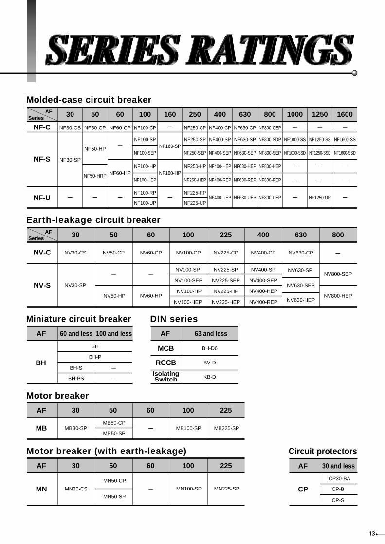
SERIES RATINGSMolded-case circuit breaker
Motor breaker
30
MB30-SP MB50-CP
MB
50 60 100 225
MB50-SPMB100-SP MB225-SP
AF
Series
NF-U
NF-C
NF-S
NV30-CS ----
--------
----
----
----
----
AF
Earth-leakage circuit breaker
Circuit protectorsMotor breaker (with earth-leakage)
Series 30
NV30-SP
NV50-CP NV60-CP
NV100-SP
NV100-SEP
NV60-HP NV100-HP
NV100-HEP NV50-HP
NV-C
NV-SNV225-SEP NV400-SEP
NV630-SEP
50 60 100 225 400 630 800
NV100-CP NV225-CP NV400-CP NV630-CP
NV225-SP NV400-SP NV630-SP NV800-SEP
NV225-HP NV400-HEP
NV630-HEPNV800-HEP
NV225-HEP NV400-REP
AF
30
MN30-CS
MN50-CP
MN50-SPMN
50 60 100 225
MN100-SP MN225-SP
AF
Miniature circuit breaker
60 and less 100 and less
BH
BH-P
BH-S
BH-PS
BH
AF
30 and less
CP30-BA
CP-B
CP-S
CP
AF
DIN series
63 and less
BH-D6
BV-D
KB-D
MCB
RCCB
IsolatingSwitch
AF
NF30-CS
NF30-SP
---- ---- ----
----
NF50-CP
NF50-HP
NF50-HRP
NF60-CP NF100-CP
NF100-SP
NF100-SEP
NF100-HP
NF100-HEP
NF100-RP
NF100-UP
NF250-CP
NF250-SP
NF250-SEP
NF250-HP
NF250-HEP
NF225-RP
NF225-UP
NF400-CP
NF400-SP
NF400-SEP
NF400-HEP
NF400-REP
NF400-UEP
NF630-CP
NF630-SP
NF630-SEP
NF630-HEP
NF630-REP
NF630-UEP
NF800-CEP
NF800-SDP
NF800-SEP
NF800-HEP
NF800-REP
NF800-UEP
----
NF1000-SS
NF1000-SSD
----
----
----
----
NF1250-SS
NF1250-SSD
----
----
NF1250-UR
----
NF1600-SS
NF1600-SSD
----
----
----
NF60-HP
----
NF160-SP
----
NF160-HP
30 50 60 100 160 250 400 630 800 1000 1250 1600
13
14
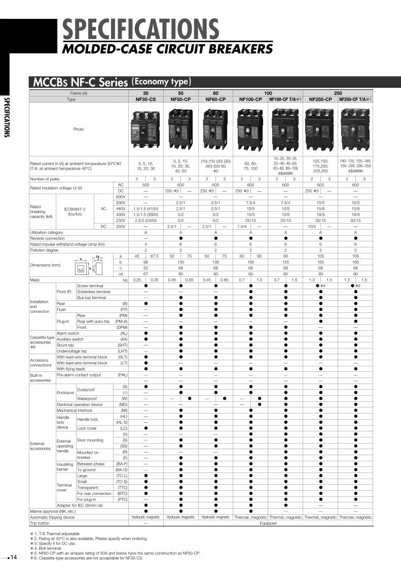
SPECIFICATIONS
SPECIFICATIONS
MOLDED-CASE CIRCUIT BREAKERS
)A(emarF 03 05 06 100 250epyT SC-03FN PC-05FN PC-06FN PC-001FN A/TPC-001FN ✳ 1 PC-052FN A/TPC-052FN ✳ 1
otohP
03erutarepmettneibmata)A(nItnerrucdetaR °C✳ 204erutarepmettneibmata:A/T( ° )C
,01,5,303,02,51
,01,5,3,03,02,51
05,04
)03()02()51()01(06)05()04(
✳ 5
,06,05001,57
,52~02,02~51,36~04,04~52001~08,08~36
elbatsujda
,051,521,002,571
052,522
,061~521,521~001052~002,002~051
elbatsujda
selopforebmuN 2 3 2 3 2 3 2 3 2 3 2 3 2 3
)V(iUegatlovnoitalusnidetaRCA 005 006 006 006 006 006 006CD — 052 ✳ 3 — 052 ✳ 3 — 052 ✳ 3 — — 052 ✳ 3 — —
detaRgnikaerb
)Ak(yticapac
2-74906CEI)scI/ucI(
CA
V096 — — — — — — —V005 — 1/5.2 1/5.2 4/5.7 4/5.7 5/01 5/01V044 1/5.2 1/5.2 5/01 5/01 8/51 8/51V004 2/5 2/5 5/01 5/01 9/81 9/81V032 2/5 2/5 31/52 31/52 51/03 51/03
CD V052 — 1/5.2 — 1/5.2 — 4/5.7 — — 5/01 — —yrogetacnoitazilitU A A A A A A AnoitcennocesreveR — ● ● ● ● ● ●
Rated impulse withstand voltage Uimp (kV) 4 6 6 6 6 6 6eergednoitulloP 2 2 2 2 2 2 2
)mm(snoisnemiD
a 54 5.76 05 57 05 57 06 09 09 501 501b 69 031 031 551 551 561 561c 25 86 86 86 86 86 86ac 76 09 09 09 09 09 09
Mass gk 52.0 53.0 54.0 56.0 54.0 56.0 7.0 0.1 7.0 0.1 3.1 5.1 3.1 5.1
noitallatsnIdna
noitcennoc
)F(tnorFlanimretwercS ● ● ● ● ● ● ✳ 4 ● ✳ 4
lanimretsselredloS — — — ● ● ● ●
lanimretrabsuB — ● ● ● ● ● ●
raeR )B( ● ● ● ● ● ● ●
hsulF )PF( — ● ● ● ● ● ●
ni-gulPraeR )MP( — ● ● ● ● ● ●
pirt-otuahtiwraeR (PM-A) — — — — — ● ●
tnorF )MPD( — ● ● ● ● — —
epyt-ettessaCseirossecca
✳ 6
hctiwsmralA )LA( ● ● ● ● ● ● ●
hctiwsyrailixuA )XA( ● ● ● ● ● ● ●
pirttnuhS )THS( — ● ● ● ● ● ●
pirtegatlovrednU )TVU( — ● ● ● ● ● ●
yrosseccAsnoitcennoc
kcolblanimreteriw-daelhtiW )TLS( ●
●
● ● ● ● ● ●
sdaelgniylfhtiW ● ● ● ● ● ● ●
ni-tliuBseirossecca
tuptuotcatnocmrala-erP )LAP( — — — — — — —— — — — — — —
lanretxEseirossecca
erusolcnEfoorptsuD
)S( ● ● ● ● ● ● ●
)I( — ● ● ● ● ● ●
foorpretaW )W( — — ● — ● — ● ● ● ●
ecivednoitarepolacirtcelE )DM( — — — — ● ● ● ●
kcolretnilacinahceM )IM( — ● ● ● ● ● ●
eldnaHkcol
ecived
kcoleldnaH)LH( — ● ● ● ● ● ●
)S-LH( — ● ● ● ● ● ●
revockcoL )CL( ● ● ● ● ● ● ●
lanretxEgnitarepo
eldnah
gnitnuomrooD)V( — — — ● ● ● ●
)S( — ● ● ● ● ● ●
)SS( — ● ● ● ● ● ●
nodetnuoMrekaerb
)R( — — — ● ● ● ●
)F( — ● ● ● ● ● ●
gnitalusnIreirrab
esahpneewteB )F-AB( — ● ● ● ● ● ●
dnuorgoT )G-AB( — ● ● ● ● ● ●
lanimreTrevoc
egraL )L-CT( ● ● ● ● ● ● ●
llamS )S-CT( ● ● ● ● ● ● ●
tnerapsnarT )CTT( ● ● ● ● ● ● ●
noitcennocraerroF )CTB( ● ● ● ● ● ● ●
ni-gulproF )CTP( — ● ● ● ● ● ●
liarmm53CEIrofretpadA ● ● ● ● ● — —).cte,KN(lavorppaeniraM ● ● ● ● — — —
ecivedgnippirtcitamotuA citengam-ciluardyH citengam-ciluardyH citengam-ciluardyH citengam,lamrehT citengam,lamrehT citengam,lamrehT citengam,lamrehTnottubpirT — deppiuqE
✳ .elbatsujdalamrehTA/T.1✳ 04tagnitaR.2 ° .gniredronehwyficepsesaelP.elbaliavaoslasiC✳ .esuCDroffiyficepS.3✳ .lanimrettloB.4✳ .PC-05FNsanoitcurtsnocemasehtevahwolebdnaA05fognitarerepmanahtiwPC-06FN.5✳ Cassette-type accessories are not acceptable for NF30-CS..6
kcolblanimreteriw-daelhtiW )TL( — — — — — —
1.5/1.5 (380V)1.5/1.5 (415V)
2.5/2 (240V)
MCCBS NF-C Series (Economy type )
a
b
cac

15
SPECIFICATIONS
SPECIFICATIONSMOLDED-CASE CIRCUIT BREAKERS
)A(emarF 004 036 008epyT PC-004FN PC-036FN PEC-008FN
otohP
04erutarepmettneibmata)A(nItnerrucdetaR °C 004,053,003,052 036,006,005 elbatsujda008~004selopforebmuN 2 3 2 3 3
)V(iUegatlovnoitalusnidetaRCA 006 006 006CD — — —
gnikaerbdetaR)Ak(yticapac
2-74906CEI)scI/ucI(
CA
V096 — — —V005 8/51 9/81 9/81V044 31/52 81/63 81/63V514 81/63 81/63 81/63V004 81/63 81/63 81/63V083 02/04 02/04 02/04V032 52/05 52/05 52/05
CD V052 01/02 — 01/02 — —yrogetacnoitazilitU A A B
Icw (kA)tnerrucdnatshtiwemit-trohsdetaR — — 6.9)Vk(pmiUegatlovdnatshtiweslupmidetaR 8 8 8
eergednoitulloP 3 3 3noitcennocesreveR ● ● ●
)mm(snoisnemiD
a 041 012 012b 752 572 572c 301 301 301ac 431 551 551
Mass )gk( 7.4 5.5 0.8 4.9 9.01
noitallatsnIdna
noitcennoc
)F(tnorFlanimretwercS — — —
lanimretsselredloS ● ● ●
lanimretrabsuB ● ● ●
raeR )B( ● ● ●
hsulF )PF( ● ● ●
ni-gulPraeR )MP( ● ● ●
Rear with auto-trip )A-MP( — — —tnorF )MPD( — — —
epyt-ettessaCseirossecca
hctiwsmralA )LA( ● ● ●hctiwsyrailixuA )XA( ● ● ●
pirttnuhS )THS( ● ● ●
pirtegatlovrednU )TVU( ● ● ●
yrosseccAsnoitcennoc
eriw-daelhtiWkcolblanimret )TLS( ● ● ●
sdaelgniylfhtiW ● ● ●
ni-tliuBseirosecca
mrala-erPtuptuotcatnoc )LAP( — — ✳● 2
rotacidnIpirT )IT( — — ●
lanretxEseirosecca
erusolcnEfoorptsuD
)S( — — —)I( ● ● ●
foorpretaW )W( ● ● ●
lacirtcelEnoitarepo
ecived
-rotoMepytdetarepo )DM( ● ● ●
-gnirpSepytegrahc )SDM( ● ● ●
kcolretnilacinahceM )IM( ● ● ●
kcoleldnaHecived
kcoleldnaH)LH( ● ● ●
)S-LH( ● ● ●
revockcoL )CL( — — —
lanretxEgnitarepo
eldnah
gnitnuomrooD)V( ● ● ●
)S( ● ● ●
)SS( ● ● ●
nodetnuoMrekaerb
)R( ● ● ●
)F( ● ● ●
gnitalusnIreirrab
esahpneewteB )F-AB( ● ● ●
dnuorgoT )G-AB( ● ● ●
lanimreTrevoc
egraL )L-CT( ● ● ●
llamS )S-CT( — — —tnerarapsnarT )CTT( ● ● ●
noitcennocraerroF )CTB( ● ● ●
ni-gulproF )CTP( ● — —liarmm53CEIrofretpadA — — —
).cte,KN(lavorppaeniraM ● ● ●
ecivedgnippirtcitamotuA citengam,lamrehT citengam,lamrehT cinortcelEnottubpirT deppiuqE
✳ .esuCDroffiyficepS.1✳ .2 ).deppiuqeTLSsuhtsiepytdradnatS(.yrassecensituptuotcatnocfiyficepsesaelPoption.situptuoyaleretatsdiloS
250 ✳ 1 250 ✳ 1
a
b
cac

16
SPECIFICATIONS
SPECIFICATIONS
MOLDED-CASE CIRCUIT BREAKERS
)A(emarF 03 50 06 001
epyT PS-03FN PH-05FN PRH-05FN PH-06FN PS-001FN A/TPS-001FN ✳ 1
otohP
erutarepmettneibmata)A(nItnerrucdetaR03 °C✳ 2 04erutarepmettneibmata:A/T( ° )C
,01,5,303,02,51
,02,51,0105,04,03
,02,5105,04,03
)02()51()01(06)05()04()03(
✳ 4
,03,02,51,06,05,04
001,57
,52~02,02~51,36~04,04~52001~08,08~36
elbatsujdaselopforebmuN 2 3 2 3 4 2 3 2 3 4 2 3 4 2 3 4
)V(iUegatlovnoitalusnidetaRCA 006 006 096 006 096 096
CD 052 ✳ 3 — 052 ✳ 3 — 052 ✳ 3 — 052 ✳ 3 — 052 ✳ 3 — —
gnikaerbdetaR)Ak(yticapac )scI/ucI(2-74906CEI
CA
V096 — — 1/5.2 — — —
V005 1/5.2 4/5.7 01/02 4/5.7 8/51 8/51
V044 1/5.2 5/01 51/03 5/01 31/52 31/52
V004 2/5 5/01 51/03 5/01 51/03 51/03
V032 2/5 31/52 34/58 31/52 52/05 52/05
CD V052 1/5.2 — 4/5.7 — 02/04 — 4/5.7 — 8/51 — —
yrogetacnoitazilitU A A A A A A
noitcennocesreveR ● ● ● ● ● ●
Rated impulse withstand voltage Uimp (kV) 6 6 6 6 6 6
eergednoitulloP 2 2 2 2 2 2
)mm(snoisnemiD
a 05 57 05 57 001 09 05 57 001 06 09 021 09 021
b 031 031 551 031 551 551
c 86 86 86 86 86 86
ac 09 09 09 09 09 09
Mass gk 54.0 56.0 55.0 57.0 0.1 8.0 1.1 55.0 57.0 0.1 57.0 1.1 4.1 57.0 1.1 4.1
dnanoitallatsnInoitcennoc
tnorF )F(
lanimretwercS ● ● ● ● ● ●
lanimretsselredloS — — ● — ● ●
lanimretrabsuB ● ● ● ● ● ●
raeR )B( ● ● ● ● ● ●
hsulF )PF( ● ● ● ● ● ●
ni-gulP
raeR )MP( ● ● ● ● ● ●
pirt-otuahtiwraeR )A-MP( — — — — — —
tnorF )MPD( ● ● — ● ● — ● — ● —
epyt-ettessaCseirossecca
hctiwsmralA )LA( ● ● ● ● ● ●
hctiwsyrailixuA )XA( ● ● ● ● ● ●
pirttnuhS )THS( ● ● ● ● ● ●
pirtegatlovrednU )TVU( ● ● ● ● ● ●
yrosseccAsnoitcennoc
kcolblanimreteriw-daelhtiW )TLS( ● ● ● ● ● ●
sdaelgniylfhtiW ● ● ● ● ● ●
ni-tliuBseirossecca
tuptuotcatnocmrala-erP )LAP( — — — — — —
lanretxEseirossecca
erusolcnEfoorptsuD
)S( ● ● — ● ● — ● — ● —
)I( ● ● — ● ● — ● — ● —
foorpretaW )W( — ● — ● — ● — ● — — ● — ● —
ecivednoitarepolacirtcelE )DM( — — ● — — ● ●
kcolretnilacinahceM )IM( ● ● ● ● ● ●
kcoleldnaHecived
kcoleldnaH)LH( ● ● ● ● ● ●
)S-LH( ● ● ● ● ● ●
revockcoL )CL( ● ● ● ● ● ●
lanretxEgnitarepo
eldnah
gnitnuomrooD
)V( — — ● — ● ●
)S( ● ● ● ● ● ●
)SS( ● ● ● ● ● ●
nodetnuoMrekaerb
)R( — — ● — ● ●
)F( ● ● ● ● ● ●
gnitalusnIreirrab
esahpneewteB )F-AB( ● ● ● ● ● ●
dnuorgoT )G-AB( ● ● ● ● ● ●
lanimreTrevoc
egraL )L-CT( ● ● ● ● ● ●
llamS )S-CT( ● ● — ● ● — ● — ● —
tnerapsnarT )CTT( ● ● — ● ● — ● — ● —noitcennocraerroF )CTB( ● ● — ● ● — ● — ● —
ni-gulproF )CTP( ● ● — ● ● — ● — ● —
liarmm53CEIrofretpadA ● ● — ● ● — ● — ● —
).cte,KN(lavorppaeniraM ● ● — ● ● — ● — —
ecivedgnippirtcitamotuA citengam-ciluardyH citengam-ciluardyH citengam,lamrehT citengam-ciluardyH citengam,lamrehT citengam,lamrehT
nottubpirT deppiuqE
✳ .1 .elbatsujdalamrehTA/T✳ 04tagnitaR.2 ° .gniredronehwyficepsesaelP.elbaliavaoslasiC✳ .esuCDroffiyficepS.3✳ 05FNsanoitcurtsnocemasehtevahwolebdnaA05fognitarerepmanahtiwPH-06FN.4 - PH
MCCBS NF-S Series (Standard type)
a
b
cac

17
SPECIFICATIONS
SPECIFICATIONSMOLDED-CASE CIRCUIT BREAKERS
)A(emarF 001 061epyT PES-001FN PH-001FN A/TPH-001FN ✳ 1 PEH-001FN PS-061FN A/TPS-061FN ✳ 1 PH-061FN
otohP
03erutarepmettneibmata)A(nItnerrucdetaR °C✳ 204erutarepmettneibmata:A/T( ° )C
)02-51(,05-03001-06
elbatsujda
,05,04,03,02,51001,57,06
,04~52,52~02,02~51,08~36,36~04
001~08elbatsujda
,)02~51(001~06,05~03
elbatsujda
,)57(,)06(,)05(051,521,)001(
061
,521~001,)08~36(061~521,)001~08(
elbatsujda
,)57(,)06(,)05(051,521,)001(
061
selopforebmuN 3 4 2 3 4 2 3 4 3 4 2 3 4 2 3 4 2 3 4
)V(iUegatlovnoitalusnidetaRCA 096 096 096 096 096 096 096CD — 052 ✳ 3 — — — 052 ✳ 3 — — 052 ✳ 3 —
gnikaerbdetaR)Ak(yticapac )scI/ucI(2-74906CEI
CA
V096 — 3/5 3/5 3/5 — — 3/5V005 8/51 51/03 51/03 51/03 8/51 8/51 8/03V044 31/52 52/05 52/05 52/05 31/52 31/52 31/05V004 51/03 52/05 52/05 52/05 51/03 51/03 31/05V032 52/05 05/001 05/001 05/001 52/05 52/05 52/001
CD V052 — 02/04 — — — 8/51 — — 02/04 —yrogetacnoitazilitU A A A A A A AnoitcennocesreveR ● ● ● ● ● ● ●
Rated impulse withstand voltage Uimp (kV) 6 6 6 6 6 6 6eergednoitulloP 2 2 2 2 2 2 2
)mm(snoisnemiD
a 09 021 09 021 09 021 501 041 501 041 501 041b 551 551 551 561 561 561c 86 86 86 86 86 86 86ac 09 09 09 29 29 29
Mass gK 2.1 5.1 57.0 1.1 4.1 57.0 1.1 4.1 2.1 5.1 3.1 5.1 9.1 3.1 5.1 9.1 3.1 5.1 9.1
dnanoitallatsnInoitcennoc
dexiFtnorF
)F(
lanimretwercS ● ● ● ● ● ✳ 4 ● ✳ 4 ● ✳ 4
lanimretsselredloS ● ● ● ● ● ● ●
lanimretrabsuB ● ● ● ● ● ● ●
raeR )B( ● ● ● ● ● ● ●
hsulF )PF( ● ● ● ● ● ● ●
ni-gulPraeR )MP( ● ● ● ● ● ● ●
pirt-otuahtiwraeR )A-MP( — — — — ● ● ●
tnorF )MPD( — ● — ● — — — — —
epyt-ettessaCseirossecca
hctiwsmralA )LA( ● ● ● ● ● ● ●
hctiwsyrailixuA )XA( ● ● ● ● ● ● ●
pirttnuhS )THS( ● ● ● ● ● ● ●
pirtegatlovrednU )TVU( ● ● ● ● ● ● ●
yrosseccAsnoitcennoc
kcolblanimreteriw-daelhtiW )TLS( ● ● ● ● ● ● ●
sdaelgniylfhtiW ● ● ● ● ● ● ●
ni-tliuBseirossecca
tuptuotcatnocmrala-erP )LAP( — — — — —
lanretxEseirossecca
erusolcnEfoorptsuD
)S( ● — ● — ● — ● — ● — ● — —)I( ● — ● — ● — ● — ● — ● — ● —
foorpretaW )W( ● — ● — ● — ● — ● — ● — ● —ecivednoitarepolacirtcelE )DM( ● ● ● ● ● ● ●
kcolretnilacinahceM )IM( ● ● ● ● ● ● ●
kcoleldnaHecived
kcoleldnaH)LH( ● ● ● ● ● ● ●
)S-LH( ● ● ● ● ● ● ●
revockcoL )CL( ● ● ● ● ● ● ●
lanretxEgnitarepo
eldnah
gnitnuomrooD)V( ● ● ● ● ● ● ●
)S( ● ● ● ● ● ● ●
)SS( ● ● ● ● ● ● ●
nodetnuoMrekaerb
)R( ● ● ● ● ● ● ●
)F( ● ● ● ● ● ● ●
gnitalusnIreirrab
esahpneewteB )F-AB( ● ● ● ● ● ● ●
dnuorgoT )G-AB( ● ● ● ● ● ● ●
lanimreTrevoc
egraL )L-CT( ● ● ● ● ● ● ●
llamS )S-CT( ● — ● — ● — ● — ● — ● — ● —tnerapsnarT )CTT( ● — ● — ● — ● — ● — ● — ● —
noitcennocraerroF )CTB( ● — ● — ● — ● — ● — ● — ● —ni-gulproF )CTP( ● — ● — ● — ● — ● — ● — ● —
liarmm53CEIrofretpadA ● — ● — ● — ● — — — —).cte,KN(lavorppaeniraM — ● — — — — — — —
ecivedgnippirtcitamotuA cirtcelE citengam,lamrehT citengam,lamrehT cinortcelE citengam,lamrehT citengam,lamrehT citengam,lamrehTnottubpirT deppiuqE
✳ .elbatsujdalamrehTA/T.1✳ 04tagnitaR.2 ° .gniredronehwyficepsesaelP.elbaliavaoslasiC✳ .esuCDroffiyficepS.3✳ .lanimrettloB.4✳ . Solid state relay output is option. Please specify if other output is necessary. (Standard type is thus SLT equipped.)5
90 120155
90
● ✳ 5 ● ✳ 5
a
b
cac

18
SPECIFICATIONS
SPECIFICATIONS
MOLDED-CASE CIRCUIT BREAKERS
)A(emarF 061 052epyT A/TPH-061FN ✳ 1 PS-052FN A/TPS-052FN ✳ 1 PES-052FN PH-052FN A/TPH-052FN ✳ 1 PEH-052FN
otohP
03erutarepmettneibmata)A(nItnerrucdetaR °C✳ 204erutarepmettneibmata:A/T( ° )C
,521~001,)08~36(061~521,)001~08(
elbatsujda
051,521,002,571
052,522
,521~001,061~521,002~051
052~002elbatsujda
052~521elbatsujda
,571,051,521052,522,002
,521~001,061~521,002~051
052~002elbatsujda
052~521elbatsujda
selopforebmuN 2 3 4 2 3 4 2 3 4 3 4 2 3 4 2 3 4 3 4
)V(iUegatlovnoitalusnidetaRCA 096CD — 052 ✳ 3 — — — 052 ✳ 3 — — —
gnikaerbdetaR)Ak(yticapac )scI/ucI(2-74906CEI
CA
V096 5/3 — — — 3/5 3/5V005 8/03 8/51 8/51 8/51 8/03 8/03V044 31/05 31/52 31/52 31/52 31/05 31/05V004 31/05 51/03 51/03 51/03 31/05 31/05V032 52/001
5/38/0331/0531/0552/00152/05 52/05 52/05 52/001 52/001
CD V052 — 8/51 — — — 02/04 — — —yrogetacnoitazilitU A A A A A A AnoitcennocesreveR ● ● ● ● ● ● ●
Rated impulse withstand voltage Uimp (kV) 6 6 6 6 6 6 6eergednoitulloP 2 2 2 2 2 2 2
)mm(snoisnemiD
a 501 041 501 041 501 041 501 041 501 041 501 041 501 041b 561 561 561 561 561 561 561c 86 86 86 86 86 86 86ac 29 09 29 29 29 29 29
Mass gK 3.1 5.1 9.1 3.1 5.1 9.1 3.1 5.1 9.1 6.1 1.2 3.1 5.1 9.1 3.1 5.1 9.1 6.1 1.2
dnanoitallatsnInoitcennoc
dexiFtnorF
)F(
lanimretwercS ● ✳ 4 ● ✳ 4 ● ✳ 4 ● ✳ 4 ● ✳ 4 ● ✳ 4 ● ✳ 4
lanimretsselredloS ● ● ● ● ● ● ●
lanimretrabsuB ● ● ● ● ● ● ●
raeR )B( ● ● ● ● ● ● ●
hsulF )PF( ● ● ● ● ● ● ●
ni-gulPraeR )MP( ● ● ● ● ● ● ●
pirt-otuahtiwraeR )A-MP( ● ● ● ● ● ● ●
tnorF )MPD( — — — — — — —
epyt-ettessaCseirossecca
hctiwsmralA )LA( ● ● ● ● ● ● ●
hctiwsyrailixuA )XA( ● ● ● ● ● ● ●
pirttnuhS )THS( ● ● ● ● ● ● ●
pirtegatlovrednU )TVU( ● ● ● ● ● ● ●
yrosseccAsnoitcennoc
kcolblanimreteriw-daelhtiW )TLS( ● ● ● ● ● ● ●
sdaelgniylfhtiW ● ● ● ● ● ● ●
ni-tliuBseirossecca
tuptuotcatnocmrala-erP )LAP( — — — — — ● ✳ 5
lanretxEseirossecca
erusolcnEfoorptsuD
)S( — ● — ● — ● — — — —
● ✳ 5
)I( ● — ● — ● — ● — ● — ● — ● —foorpretaW )W( ● — ● — ● — ● — ● — ● — ● —ecivednoitarepolacirtcelE )DM( ● ● ● ● ● ● ●
kcolretnilacinahceM )IM( ● ● ● ● ● ● ●
kcoleldnaHecived
kcoleldnaH)LH( ● ● ● ● ● ● ●
)S-LH( ● ● ● ● ● ● ●
revockcoL )CL( ● ● ● ● ● ● ●
lanretxEgnitarepo
eldnah
gnitnuomrooD)V( ● ● ● ● ● ● ●
)S( ● ● ● ● ● ● ●
)SS( ● ● ● ● ● ● ●
nodetnuoMrekaerb
)R( ● ● ● ● ● ● ●
)F( ● ● ● ● ● ● ●
gnitalusnIreirrab
esahpneewteB )F-AB( ● ● ● ● ● ● ●
dnuorgoT )G-AB( ● ● ● ● ● ● ●
lanimreTrevoc
egraL )L-CT( ● ● ● ● ● ● ●
llamS )S-CT( ● — ● — ● — ● — ● — ● — ● —tnerapsnarT )CTT( ● — ● — ● — ● — ● — ● — ● —
raerroFnoitcennoc )CTB( ● — ● — ● — ● — ● — ● — ● —
ni-gulproF )CTP( ● — ● — ● — ● — ● — ● — ● —liarmm53CEIrofretpadA — — — — — — —
).cte,KN(lavorppaeniraM — — — — — — —ecivedgnippirtcitamotuA citengam,lamrehT citengam,lamrehT citengam,lamrehT cinortcelE citengam,lamrehT citengam,lamrehT cinortcelE
nottubpirT deppiuqE
✳ .elbatsujdalamrehTA/T.1✳ 04tagnitaR.2 ° .gniredronehwyficepsesaelP.elbaliavaoslasiC✳ .esuCDroffiyficepS.3✳ .lanimrettloB.4✳ Solid state relay output is option. Please specify if other output is necessary. (Standard type is thus SLT equipped.).5
MCCBS NF-S Series (Standard type)
a
b
cac

19
SPECIFICATIONS
SPECIFICATIONSMOLDED-CASE CIRCUIT BREAKERS
)A(emarF 004epyT PS-004FN PES-004FN PEH-004FN PER-004FN
otohP
)A(nItnerrucdetaR04erutarepmettneibmata °C 004,053,003,052 002 ~ 004
elbatsujda002 ~ 004
elbatsujda002 ~ 004
elbatsujda
selopforebmuN 2 3 4 3 4 3 4 3
)V(iUegatlovnoitalusnidetaRCA 096 096 096 096CD — — — —
detaRgnikaerb
)Ak(yticapac
2-74906CEI)scI/ucI(
CA
V096 01/01 01/51V005 05/05 53/07V044 56/56 36/521V514 07/07 36/521V004 07/07 36/521V083 07/07 36/521V032 001/001 57/051
CD V052 04/04 — — — —yrogetacnoitazilitU A B B B
)Ak(wcItnerrucdnatshtiwemit-trohsdetaR — 5 5 5)Vk(pmiUegatlovdnatshtiweslupmidetaR 8 8 8 8
eergednoitulloP 3 3 3 3noitcennocesreveR ● ● ● ●
)mm(snoisnemiD
a 041 581 041 581 041 581 041
b 752 752 752 752
c 301 301 301 301
ac 551 551 551 551
Mass )gk( 9.4 7.5 5.7 6 8.7 6 8.7 6
noitallatsnIdna
noitcennoc
)F(tnorFlanimretwercS — — — —
— —lanimretsselredloS ● ●
● ●lanimretrabsuB ● ●
raeR )B( ● ● ● ●
hsulF )PF( ● ● ● ●
ni-gulPraeR )MP( ● ● ● ●
Rear with auto-trip )A-MP( — — — —tnorF )MPD( — — — —
epyt-ettessaCseirossecca
hctiwsmralA )LA( ● ● ● ●
hctiwsyrailixuA )XA( ● ● ● ●
pirttnuhS )THS( ● ● ● ●
pirtegatlovrednU )TVU( ● ● ● ●
yrosseccAsnoitcennoc
kcolblanimreteriw-daelhtiW )TLS( ● ● ● ●
sdaelgniylfhtiW ● ● ● ●
ni-tliuBseirosseccA
tuptuotcatnocmrala-erP )L-M AP( — ✳● 2 ✳● 2 ✳● 2rotacidnipirT )IT( — ● ● ●
lanretxEseirossecca
erusolcnEfoorptsuD
)S( — — — —)I( ● — ● — — —
foorpretaW )W( ● — ● — — —
lacirtcelEnoitarepo
ecived
-repo-rotoMepytdeta )DM( ● ● ● ●
egrahc-gnirpSepyt )SDM( ● ● ● ●
kcolretnilacinahceM ● ● ● ●
kcoleldnaHecived
kcoleldnaH)LH( ● ● ● ●
)S-LH( ● ● ● ●
revockcoL )CL( — — — —
lanretxEgnitarepo
eldnah
gnitnuomrooD)V( ● ● ● ●
)S( ● ● ● ●
)SS( ● ● ● ●
nodetnuoMrekaerb
)R( ● ● ● ●
)F( ● ● ● ●
gnitalusnIreirrab
neewteBesahp )F-AB( ● ● ● ●
dnuorgoT )G-AB( ● ● ● ●
revoclanimreT
egraL )L-CT( ● ●
llamS )S-CT( — — — —— —
tnerapsnarT )CTT( ● ● ● ●
raerroFnoitcenoc )CTB( ● ● — ● —
ni-gulproF )CTP( ● — ● — ● — ●
liarmm53CEIrofretpadA — — — —).cte,KN(lavorppaeniraM ● — ● — ● — ●
ecivedgnippirtcitamotuA citengam,lamrehT cinortcelE cinortcelE cinortcelEnottubpirT deppiuqE
✳ .esuCDroffiyficepS.1✳ ).deppiuqeTLSsuhtsiepytdradnatS(.yrassecensituptuorehtofiyficepsesaelPs option.ituptuoyaleretatsdiloS.2✳ In case of solderless terminal, interrupting capacity reduces: ( / )..3
250 ✳ 110/10 (5/5) ✳ 3
30/30 (25/25) ✳ 342/42 (36/36) ✳ 345/45 (36/36) ✳ 345/45 (36/36) ✳ 350/50 (42/42) ✳ 385/85 (65/65) ✳ 3
10/10 (5/5) ✳ 330/30 (25/25) ✳ 342/42 (36/36) ✳ 345/45 (36/36) ✳ 345/45 (36/36) ✳ 350/50 (42/42) ✳ 385/85 (65/65) ✳ 3
(MI)
a
b
cac
20
SPECIFICATIONS
SPECIFICATIONS
MOLDED-CASE CIRCUIT BREAKERS
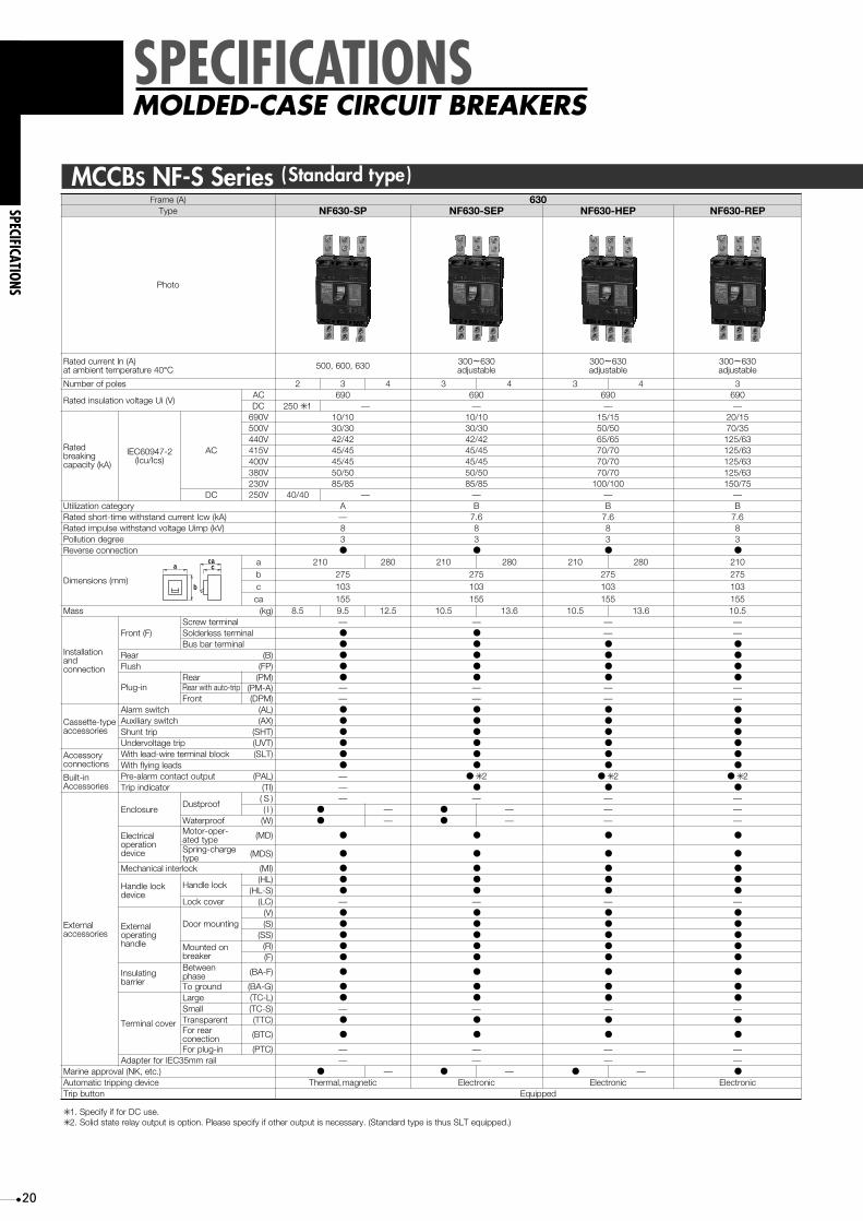
)A(emarF 036epyT PS-036FN PES-036FN PEH-036FN PER-036FN
otohP
)A(nItnerrucdetaR04erutarepmettneibmata °C 036,006,005 003 ~ 036
elbatsujda003 ~ 036
elbatsujda003 ~ 036
elbatsujda
selopforebmuN 2 3 4 3 4 3 4 3
)V(iUegatlovnoitalusnidetaRCA 096 096 096 096CD — — — —
detaRgnikaerb
)Ak(yticapac
2-74906CEI)scI/ucI(
CA
V096 01/01 01/01 51/51 51/02V005 03/03 03/03 05/05 53/07V044 24/24 24/24 56/56 36/521V514 54/54 54/54 07/07 36/521V004 54/54 54/54 07/07 36/521V083 05/05 05/05 07/07 36/521V032 58/58 58/58 001/001 57/051
CD V052 04/04 — — — —yrogetacnoitazilitU A B B B
)Ak(wcItnerrucdnatshtiwemit-trohsdetaR —)Vk(pmiUegatlovdnatshtiweslupmidetaR 8 8 8 8
eergednoitulloP 3 3 3 3noitcennocesreveR ● ● ● ●
)mm(snoisnemiD
a 012 082 012 082 012 082 012b 572 572 572 572c 301 301 301 301ac 551 551 551 551
Mass )gk( 5.8 5.9 5.21 5.01 6.31 5.01 6.31 5.01
noitallatsnIdna
noitcennoc
)F(tnorFlanimretwercS — — — —
lanimretsselredloS ● ● — —lanimretrabsuB ● ● ● ●
raeR )B( ● ● ● ●
hsulF )PF( ● ● ● ●
ni-gulPraeR )MP( ● ● ● ●
Rear with auto-trip )A-MP( — — —tnorF )MPD( — — — —
epyt-ettessaCseirossecca
hctiwsmralA )LA( ● ● ● ●
hctiwsyrailixuA )XA( ● ● ● ●
pirttnuhS )THS( ● ● ● ●
pirtegatlovrednU )TVU( ● ● ● ●
yrosseccAsnoitcennoc
kcolblanimreteriw-daelhtiW )TLS( ● ● ● ●
sdaelgniylfhtiW ● ● ● ●
ni-tliuBseirosseccA
tuptuotcatnocmrala-erP )LAP( — ✳● 2 ✳● 2 ✳● 2rotacidnipirT )IT( — ● ● ●
lanretxEseirossecca
erusolcnEfoorptsuD
)S( — — — —)I( ● — ● — — —
foorpretaW )W( ● — ● — — —
lacirtcelEnoitarepo
ecived
-repo-rotoMepytdeta )DM( ● ● ● ●
egrahc-gnirpSepyt )SDM( ● ● ● ●
kcolretnilacinahceM ● ● ● ●
kcoleldnaHecived
kcoleldnaH)LH( ● ● ● ●
)S-LH( ● ● ● ●
revockcoL )CL( — — — —
lanretxEgnitarepo
eldnah
gnitnuomrooD)V( ● ● ● ●
)S( ● ● ● ●
)SS( ● ● ● ●
nodetnuoMrekaerb
)R( ● ● ● ●
)F( ● ● ● ●
gnitalusnIreirrab
neewteBesahp )F-AB( ● ● ● ●
dnuorgoT )G-AB( ● ● ●
●
●
●
revoclanimreT
egraL )L-CT( ● ●
llamS )S-CT( — — — —tnerapsnarT )CTT( ● ● ● ●
raerroFnoitcenoc )CTB( ● ● ● ●
ni-gulproF )CTP( — — — —liarmm53CEIrofretpadA — — — —
).cte,KN(lavorppaeniraM ● — ● — ● — ●
ecivedgnippirtcitamotuA citengam,lamrehT cinortcelE cinortcelE cinortcelEnottubpirT deppiuqE
✳ .esuCDroffiyficepS.1✳ ).deppiuqeTLSsuhtsiepytdradnatS(.yrassecensituptuorehtofiyficepsesaelPoption.situptuoyaleretatsdiloS.2
—
250 ✳ 1
7.6 7.6 7.6
(MI)
MCCBS NF-S Series (Standard type)
a
b
cac
21
SPECIFICATIONS
SPECIFICATIONSMOLDED-CASE CIRCUIT BREAKERS
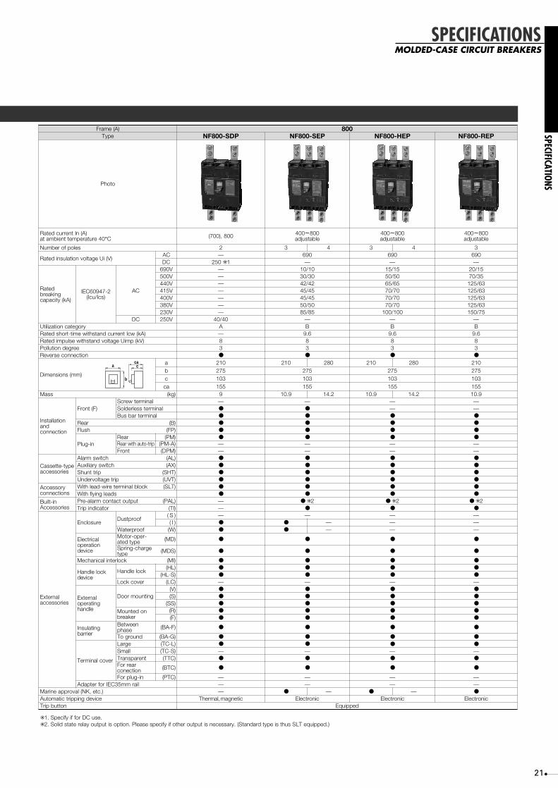
)A(emarF 008epyT PDS-008FN PES-008FN PEH-008FN PER-008FN
otohP
)A(nItnerrucdetaR04erutarepmettneibmata °C 008,)007( 004 ~ 008
elbatsujda004 ~ 008
elbatsujda004 ~ 008
elbatsujda
selopforebmuN 2 3 4 3 4 3
)V(iUegatlovnoitalusnidetaRCA — 096 096 096CD — — —
detaRgnikaerb
)Ak(yticapac
2-74906CEI)scI/ucI(
CA
V096 — 01/01 51/51 51/02V005 — 03/03 05/05 53/07V044 — 24/24 56/56 36/521V514 — 54/54 07/07 36/521V004 — 54/54 07/07 36/521V083 — 05/05 07/07 36/521V032 — 58/58 001/001 57/051
CD V052 04/04 — — —yrogetacnoitazilitU A B B B
)Ak(wcItnerrucdnatshtiwemit-trohsdetaR — 6.9 6.9 6.9)Vk(pmiUegatlovdnatshtiweslupmidetaR 8 8 8 8
eergednoitulloP 3 3 3 3noitcennocesreveR ● ● ● ●
)mm(snoisnemiD
a 012 012 082 012 082 012b 572 572 572 572c 301 301 301 301ac 551 551 551 551
Mass )gk( 9 9.01 2.41 9.01 2.41 9.01
noitallatsnIdna
noitcennoc
)F(tnorFlanimretwercS — — — —
lanimretsselredloS ● ● — —lanimretrabsuB ● ● ● ●
raeR )B( ● ● ● ●
hsulF )PF( ● ● ● ●
ni-gulPraeR )MP( ● ● ● ●
Rear with auto-trip )A-MP( — — — —tnorF )MPD( — — — —
epyt-ettessaCseirossecca
hctiwsmralA )LA( ● ● ● ●
hctiwsyrailixuA )XA( ● ● ● ●
pirttnuhS )THS( ● ● ● ●
pirtegatlovrednU )TVU( ● ● ● ●
yrosseccAsnoitcennoc
kcolblanimreteriw-daelhtiW )TLS( ● ● ● ●
sdaelgniylfhtiW ● ● ● ●
ni-tliuBseirosseccA
tuptuotcatnocmrala-erP )LAP( — ✳● 2 ✳● 2 ✳● 2rotacidnipirT )IT( — ● ● ●
lanretxEseirossecca
erusolcnEfoorptsuD
)S( — — — —)I( ● ● — — —
foorpretaW )W( ● ● — — —
lacirtcelEnoitarepo
ecived
-repo-rotoMepytdeta )DM( ● ● ● ●
egrahc-gnirpSepyt )SDM( ● ● ● ●
kcolretnilacinahceM ● ● ● ●
kcoleldnaHecived
kcoleldnaH)LH( ● ● ● ●
)S-LH( ● ● ● ●
revockcoL )CL( — — — —
lanretxEgnitarepo
eldnah
gnitnuomrooD)V( ● ● ● ●
)S( ● ● ● ●
)SS( ● ● ● ●
nodetnuoMrekaerb
)R( ● ● ● ●
)F( ● ● ● ●
gnitalusnIreirrab
neewteBesahp )F-AB( ● ● ● ●
dnuorgoT )G-AB( ● ● ●
●
●
●
revoclanimreT
egraL )L-CT( ● ●
llamS )S-CT( — — — —tnerapsnarT )CTT( ● ● ● ●
raerroFnoitcenoc )CTB( ● ● ● ●
ni-gulproF )CTP( — — — —liarmm53CEIrofretpadA — — — —
).cte,KN(lavorppaeniraM — ● — ● — ●
ecivedgnippirtcitamotuA citengam,lamrehT cinortcelE cinortcelE cinortcelEnottubpirT deppiuqE
✳ .esuCDroffiyficepS.1✳ ).deppiuqeTLSsuhtsiepytdradnatS(.yrassecensituptuorehtofiyficepsesaelPoption.situptuoyaleretatsdiloS.2
250 ✳ 1
(MI)
a
b
cac

22
SPECIFICATIONS
SPECIFICATIONS
MOLDED-CASE CIRCUIT BREAKERS
)A(emarF 12501000epyT NF1000-SS NF1000-SSD NF1250-SS NF1250-SSD
otohP
)A(nItnerrucdetaR04erutarepmettneibmata °C 1000 600-700-800-
1000-1200-1250 adjustable1250
selopforebmuN 3 4—
3 4 2
)V(iUegatlovnoitalusnidetaRCA
2096
CD 250 ✳ 1 —
—
—
—
———————
—
detaRgnikaerb
)Ak(yticapac
2-74906CEI)scI/ucI(
CA
V096 — 25/13V005 — 65/33V044 — 85/43V514 —V004 — 85/43V083 —V032 — 125/63
CD V052 40/20 — 40/20yrogetacnoitazilitU A B A
)Ak(wcItnerrucdnatshtiwemit-trohsdetaR — 20)Vk(pmiUegatlovdnatshtiweslupmidetaR 8 8 8
eergednoitulloP 3 3 3noitcennocesreveR ● ● ●
)mm(snoisnemiD
a 012 012 082 012b 406 406 406c 140 140 140ac 190
22190 190
Mass )gk( 23.5 30.7 22
noitallatsnIdna
noitcennoc
)F(tnorFlanimretwercS — — —
lanimretsselredloS — — —lanimretrabsuB ● ● ●
raeR )B( ● ● ●
hsulF )PF( ● ● ●
ni-gulPraeR )MP( — ●
Rear with auto-trip )A-MP( — — ——
tnorF )MPD( — — —
seirossecca
hctiwsmralA )LA( ● ● ●
hctiwsyrailixuA )XA( ● ● ●
pirttnuhS )THS( ● ● ●
pirtegatlovrednU )TVU( ● ● ●
yrosseccAsnoitcennoc
kcolblanimreteriw-daelhtiW )TL( ● ● ●
sdaelgniylfhtiW ● ● ●
ni-tliuBseirosseccA
tuptuotcatnocmrala-erP )LAP( ——rotacidnipirT )IT(
lanretxEseirossecca
erusolcnEfoorptsuD
)S( — —
——
—
——
)I( ● — ●
foorpretaW )W( ●
●
● — ●
lacirtcelEnoitarepo
ecived
-repo-rotoMepytdeta )DM( ● ● ●
egrahc-gnirpSepyt )SDM( ● ● ●
kcolretnilacinahceM ● ● ●
kcoleldnaHecived
kcoleldnaH)LH( ● ● ●
)S-LH(revockcoL )CL( —
—
—
———
—
———
—
—
lanretxEgnitarepo
eldnah
gnitnuomrooD)V()S( ● ● ●
)SS( ● ● ●
nodetnuoMrekaerb
)R()F( ● ● ●
gnitalusnIreirrab
neewteBesahp )F-AB( ● ● ●
dnuorgoT )G-AB( ● ●
●
●
●
revoclanimreT
egraL )L-CT( ●
llamS )S-CT( ——
—
——
—
——
—
tnerapsnarT )CTT(raerroF
noitcenoc )CTB(
ni-gulproF )CTP( — — —liarmm53CEIrofretpadA —
—— —
—).cte,KN(lavorppaeniraM ——ecivedgnippirtcitamotuA Thermal, magnetic cinortcelE Thermal, magnetic
nottubpirT deppiuqE
012 082
30.7
—●
● —
(MI)
250 ✳ 1
500-600-700-800-900-1000 adjustable
690—
25/1365/3385/43
—85/43
—125/63
—B2083●
406140190
23.5——●
●
●
●
——●
●
●
●
●
●
———
●
●
●
●
———●
●
—●
●
●
●
——
—
———
Electronic
✳ Specify if for DC use..1
MCCBS NF-S Series (Standard type)
a
b
cac
23
SPECIFICATIONS
SPECIFICATIONSMOLDED-CASE CIRCUIT BREAKERS
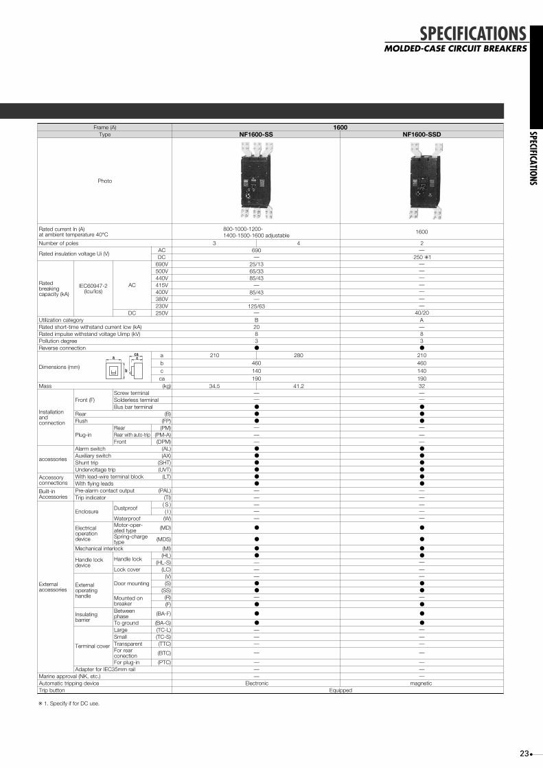
)A(emarF 1600epyT
otohP
)A(nItnerrucdetaR04erutarepmettneibmata °C
800-1000-1200-1400-1500-1600 adjustable
1600
selopforebmuN 3 4 2
)V(iUegatlovnoitalusnidetaRCA —CD
detaRgnikaerb
)Ak(yticapac
2-74906CEI)scI/ucI(
CA
V096 25/1365/3385/43
85/43
125/63
—
V005V044V514 —V004V083 —
—V032
CD V052 40/20—
—
——————
yrogetacnoitazilitU B A)Ak(wcItnerrucdnatshtiwemit-trohsdetaR 20)Vk(pmiUegatlovdnatshtiweslupmidetaR 8 8
eergednoitulloP 3 3noitcennocesreveR ● ●
)mm(snoisnemiD
a 012 082 012b 460 460c 140 140ac 190 190
Mass )gk( 32
noitallatsnIdna
noitcennoc
)F(tnorFlanimretwercS —
———
—
lanimretsselredloSlanimretrabsuB ● ●
raeR )B( ● ●
hsulF )PF( ● ●
ni-gulPraeR )MP(
Rear with auto-trip )A-MP( ——
—tnorF )MPD( — —
seirossecca
hctiwsmralA )LA( ● ●
hctiwsyrailixuA )XA( ● ●
pirttnuhS )THS( ● ●
pirtegatlovrednU )TVU( ● ●
yrosseccAsnoitcennoc
kcolblanimreteriw-daelhtiW )TL( ● ●
sdaelgniylfhtiW ● ●
ni-tliuBseirosseccA
tuptuotcatnocmrala-erP )LAP( —rotacidnipirT )IT( —
lanretxEseirossecca
erusolcnEfoorptsuD
)S( ———
———
——
)I(foorpretaW )W(
lacirtcelEnoitarepo
ecived
-repo-rotoMepytdeta )DM( ● ●
egrahc-gnirpSepyt )SDM( ● ●
kcolretnilacinahceM ● ●
kcoleldnaHecived
kcoleldnaH)LH( ● ●
)S-LH(revockcoL )CL( —
—
—
———
—
—
lanretxEgnitarepo
eldnah
gnitnuomrooD)V()S( ● ●
)SS( ● ●
nodetnuoMrekaerb
)R()F( ● ●
gnitalusnIreirrab
neewteBesahp )F-AB( ● ●
dnuorgoT )G-AB( ● ●
revoclanimreT
egraL )L-CT(llamS )S-CT( —
———
tnerapsnarT )CTT(raerroF
noitcenoc )CTB(
ni-gulproF )CTP( —
—
—
—
—
—
liarmm53CEIrofretpadA — ——).cte,KN(lavorppaeniraM —
ecivedgnippirtcitamotuA Electronic magneticnottubpirT deppiuqE
34.5 41.2
NF1600-SSDNF1600-SS
250 ✳ 1690
(MI)
✳ Specify if for DC use..1
a
b
cac

24
SPECIFICATIONS
SPECIFICATIONS
MOLDED-CASE CIRCUIT BREAKERS
)A(emarF 001 522
epyT PR-001FN PU-001FN PR-522FN PU-522FN
otohP
03erutarepmettneibmata)A(nItnerrucdetaR °C ✳ 1,03.02,51,06,05,04
001,57
,521,571,051
522,002
,521,571,051
522,002
selopforebmuN 2 3 2 3 4 2 3 2 3 4
)V(iUegatlovnoitalusnidetaRCA 096 096 096 096
CD 052 ✳ 2 — — 052 ✳ 2 — —
detaRgnikaerb
)Ak(yticapac)scI/ucI(2-74906CEI
CA
V096 — 5/01 — 5/01
V005 24/24 002/002 24/24 002/002
V044 521/521 002/002 521/521 002/002
V004 521/521 002/002 521/521 002/002
V032 521/521 002/002 521/521 002/002
CD V052 04/04 — — 04/04 — —
yrogetacnoitazilitU A A A A
noitcennocesreveR ● ● ● ●
Rated impulse withstand voltage Uimp (kV) 6 6 6 6
eergednoitulloP 2 2 2 2
)mm(snoisnemiD
a 09 09 021 501 501 041
b 612 612 042 042
c 86 86 86 86
ac 09 09 29 29
Mass gk 7.1 8.1 7.1 8.1 5.2 0.3 2.3 0.3 2.3 0.4
dnanoitallatsnInoitcennoc
dexiFtnorF
)F(
lanimretwercS ● ● ● ✳ 3 ● ✳ 3
lanimretsselredloS ● ● ● ●
lanimretrabsuB ● ● ● ●
raeR )B( ● ● ● ●
hsulF )PF( ● ● ● ●
ni-gulP
raeR )MP( ● ● — ● ● —pirt-otuahtiwraeR )A-MP( — — — —
tnorF )MPD( — — — —
epyt-ettessaCseirossecca
hctiwsmralA )LA( ● ● ● ●
hctiwsyrailixuA )XA( ● ● ● ●
pirttnuhS )THS( ● ● ● ●
pirtegatlovrednU )TVU( ● ● ● ●
yrosseccAsnoitcennoc
kcolblanimreteriw-daelhtiW )TLS( ● ● ● ●
sdaelgniylfhtiW ● ● ● ●
ni-tliuBseirossecca
tuptuotcatnocmrala-erP )LAP( — — — —
lanretxEseirossecca
erusolcnEfoorptsuD
)S( — — — —
)I( — — — —
foorpretaW )W( — — — —
ecivednoitarepolacirtcelE )DM( ● ● ● ●
kcolretnilacinahceM )IM( ● ● ● ●
kcoleldnaHecived
kcoleldnaH)LH( ● ● ● ●
)S-LH( ● ● ● ●
revockcoL )CL( ● ● ● ●
lanretxEgnitarepo
eldnah
gnitnuomrooD
)V( — — — —
)S( ● ● ● ●
)SS( ● ● ● ●
nodetnuoMrekaerb
)R( — — — —
)F( ● ● ● ●
gnitalusnIreirrab
esahpneewteB )F-AB( ● ● ● ●
dnuorgoT )G-AB( ● ● ● ●
lanimreTrevoc
egraL )L-CT( ● ● ● ●
llamS )S-CT( ● ● — ● ● —
tnerapsnarT )CTT( ● ● — ● ● —raerroF
noitcennoc )CTB( ● ● — ● ● —
ni-gulproF )CTP( — — — —
liarmm53CEIrofretpadA — — — —
).cte,KN(lavorppaeniraM ● ● — ● ● —
ecivedgnippirtcitamotuA citengam,lamrehT citengam,lamrehT citengam,lamrehT citengam,lamrehT
nottubpirT deppiuqE
✳ 04tagnitaR.1 ° .gniredronehwyficepsesaelP.elbaliavaoslasiC✳ .esuCDroffiyficepS.2
✳ .lanimrettloB.3
15,20,30,40,50,60,
75,100
MCCBS NF-U Series (Ultra current-limiting type )
a
b
cac
25
SPECIFICATIONS
SPECIFICATIONSMOLDED-CASE CIRCUIT BREAKERS
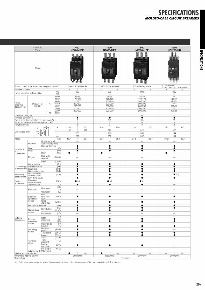
)A(emarF 004 036 008epyT PEU-004FN PEU-036FN PEU-008FN
1250NF1250-UR
otohP
04erutarepmettneibmata)A(nItnerrucdetaR °C 002 ~ elbatsujda004 003 ~ elbatsujda036 004 ~ elbatsujda008
selopforebmuN 3 4 3 4 3 4
)V(iUegatlovnoitalusnidetaR CA 096 096 096CD — — —
detaRgnikaerb
)Ak(yticapac
2-74906CEI)scI/ucI(
CA
V096 53/53 53/53 53/53V005 071/071 071/071 071/071V044 002/002 002/002 002/002V514 002/002 002/002 002/002V004 002/002 002/002 002/002V083 002/002 002/002 002/002V032 002/002 002/002 002/002
CD V052 — — —yrogetacnoitazilitU B B BnoitcennocesreveR ● ● ●
)Ak(wcItnerrucdnatshtiwemit-trohsdetaR 5 6.9Rated impulse withstand voltage Uimp (kV) 8 8 8
eergednoitulloP 3 3 3
)mm(snoisnemiD
a 041 082 012 082 012 082b 792 223 223 223c 002 002 002ac 252 252 252
Mass )gk( 7.61 1.62 7.52 9.13 6.72 7.33
noitallatsnIdna
noitcennoc
)F(tnorFlanimretwercS — — —
lanimretsselredloS — — —lanimretrabsuB ● ● ●
raeR )B( ● ● ●hsulF )PF( ● ● ●
ni-gulP
raeR )MP( ● — ● — ——
——
Rear withauto-trip )A-MP( — — —
tnorF )MPD( — — —
-pyt-ettessaCseirosseccae
hctiwsmralA )LA( ● ● ●hctiwsyrailixuA )XA( ● ● ●
pirttnuhS )THS( ● ● ●pirtegatlovrednU )TVU( ● ● ●
yrosseccAsnoitcennoc
eriw-daelhtiWkcolblanimret )TLS( ● ● ●
sdaelgniylfhtiW ● ● ●
ni-tliuBseirosecca
mrala-erPtuptuotcatnoc )LAP( ● ✳ 1 ● ✳ 1 ● ✳ 1
rotacidnIpirT )IT( ● ● ●
lanretxEseirosecca
erusolcnEfoorptsuD
)S( — — —)I( — — —
foorpretaW )W( — — —
lacirtcelEnoitarepo
ecived
-rotoMdetarepo
epyt)DM( ● ● ●
-gnirpSepytegrahc )SDM( ● ● ●
kcolretnilacinahceM )IM( ● ● ●
kcoleldnaHecived
kcoleldnaH )LH( ● ● ●)S-LH( ● ● ●
revockcoL )CL( — — —
lanretxEgnitarepo
eldnah
rooDgnitnuom
)V( — — —)S( ● ● ●)SS( ● ● ●
nodetnuoMrekaerb
)R( — — —)F( ● ● ●
gnitalusnIreirrab
neewteBesahp )F-AB( ● ● ●
dnuorgoT )G-AB( ● ● ●
lanimreTrevoc
egraL )L-CT( ● ● ●llamS )S-CT( — — —-snarT
tnerarap )CTT( — — —
raerroFnoitcennoc )CTB( ● ● ●
ni-gulproF )CTP( — — —liarmm53CEIrofretpadA — — —
).cte,KN(lavorppaeniraM ● — ● —ecivedgnippirtcitamotuA cinortcelE cinortcelE cinortcelE
nottubpirT deppiuqE
✳ ).deppiuqeTLSsuhtsiepytdradnatS(.yrassecensituptuorehtofiyficepsesaelPoption.situptuoyaleretatsdiloS.1
● —
3 4
2.73 7.64
——
600-700-800-1000-1200-1250 adjustable
096——
—
—
85/42125/65
125/65
170/85—B●
2083
240 310406144194
——●●●
—
—●●●●
● (LT)
●
——
—
——
●
●
●●
—
—
—●●—
—
●
●●—
—
—
——
cinortcelE
7.6
a
b
cac

26
SPECIFICATIONS
SPECIFICATIONS
EARTH-LEAKAGE CIRCUIT BREAKERS
)A(emarF 03 05 06 001 522epyT SC-03VN PC-05VN PC-06VN PC-001VN PC-522VN
otohP
metsysylppuS ✳ 1,W3ø3,W2ø1
W3ø1
,W3ø3,W2ø1
W3ø1
,W3ø3,W2ø1
W3ø1
,W3ø3,W2ø1
W3ø1
,W3ø3,W2ø1
W3ø1
selopforebmuN 3 3 3 3 3
eUegatlovlanoitarepodetaR VCA 032 044-004-032epytegatlov-itluM
044-004-032epytegatlov-itluM
044-004-032epytegatlov-itluM
044-004-032epytegatlov-itluM
03erutarepmettneibmata)A(nItnerrucdetaR °C ,51,01,503,02
03,02,5105,04 06 001,57,06 571,051,521
522,002
deeps-hgiHepyt
03 03 • 001 • 005elbatceleS
03 • 001 • 005elbatceleS
03 • 001 • 005elbatceleS
03 • 001 • 005elbatceleS
I5taemitgnitarepo.xaM ∆n )s( 40.0 40.0 40.0 40.0 40.0
yaled-emiTepyt
IytivitisnestnerrucdetaR ∆n )Am( — — — 001 • 003 • 005elbatceleS
001 • 003 • 005elbatceleS
— — — 54.0 • 0.1 • 0.2elbatceleS
54.0 • 0.1 • 0.2elbatceleS
— — — 1.0 • 5.0 • 0.1 1.0 • 5.0 • 0.1
metsysnoitacidniegakael-htraE nottuB nottuB nottuB nottuB nottuB
stnenopmocCDrofscitsiretcarah CAepy CAepy CAepy CAepy CAepyC T T T T T
Utilization category A A A A A
Rated impulse withstand voltage Uimp (kV) 4 6 6 6 6
Pollution degree 2 2 2 2 2
)Ak(yticapacgnikaerbdetaR2-74906CEI
scI/ucICA
V044 — 1/5.2 1/5.2 5/01 8/51
V004 — 2/5 2/5 5/01 9/81
V032 2/5.2 2/5 2/5 31/52 51/03
)mm(snoisnemiD
a 5.76 57 57 09 501
b 69 031 031 551 561
c 25 86 86 86 86
ac 76 09 09 09 29
Mass gk 4.0 65.0 75.0 1.1 7.1
noitcennoC
)F(tnorFlanimretwercS ● ● ● ● ● ✳ 2
lanimretsselredloS — — — ● ●
raeR )B( ● ● ● ● ●
ni-gulP )MP( ● ● ● ●
etalphsulF )PF( — ● ● ● ●
hctiwsmralA )LA( ● ● ● ● ●
hctiwsyrailixuA )XA( ● ● ● ● ●
hctiwsnoitalusnI )GM( ● ● ● ● ●
mralapirtegakael-htraE )LAE( — ● ✳ 4 ● ✳ 4 ● ✳ 4 ● ✳ 4
eludomnottubtseT )MBT( — ● ✳ 4 ● ✳ 4 ● ✳ 4 ● ✳ 4
kcolblanimreteriw-daeL )TLS( ● ● ● ● ●
epytdaelgniylF ● ● ● ● ●
lanretxEseirossecca
erusolcnE
foorptsuD )S( ● ● ● ● ●
foorptsuD )I( — ● ● ● ●
foorpretaW )W( — ● ● ● ●
ecivednoitarepolacirtcelE )DM( — — — ● ●
kcolretnilacinahceM )IM( — ● ● ● ●
ecivedkcoleldnaH
)LH( — ● ● ● ●
)S-LH( — ● ● ● ●
)CL( ● ● ● ● ●
eldnahgnitarepolanretxE)F( — ● ● ● ●
)S( — ● ● ● ●
revoclanimreT)L-CT( ● ● ● ● ●
)CTB( ● ● ● ● ●
raeR )TS-B( ● ● ● ● ●
hsulF )PF( — ● ● ● ●
ecivedgnippirtcitamotuA citengam-ciluardyH citengam-ciluardyH citengam-ciluardyH citengam,lamrehT citengam,lamrehT
nottubpirT — deppiuqE
✳ tondnaselopthgirdnatfelehttcennoc,ecivedesahp-2elop-1asarekaerbegakael-htraeelop-3agnisufI.1.eloplartnecehtoteriwlartuenehttcennoc,esahp-3elop-1sagnisufI.eloplartneceht
✳ lanimrettloB.2✳ 3. Cassette-type accessories are not acceptable for NV30-CS.✳ Lead-wire terminal block is equipped..4
—
Rated current sensitivity I∆n (mA)
Max. operating time at 2I∆n (s)
Inertial non-operating time at 2I∆n (s)
Cassette-typeaccessories ✳ 3
Built-inaccessories
Accessoryconnection
ELCBS NV-C Series (Economy type)
a
b
cac

27
SPECIFICATIONS
SPECIFICATIONSEARTH-LEAKAGE CIRCUIT BREAKERS
)A(emarF 004 036epyT VN 004 PC- PC-036VN
otohP
metsysylppuS ✳ 1 W2ø1,W3ø1,W3ø3 W2ø1,W3ø1,W3ø3selopforebmuN 3 3
eUegatlovlanoitarepodetaR CAV 044-004-032epytegatlov-itluM 044-004-032epytegatlov-itluM04erutarepmettneibmata)A(nItnerrucdetaR °C 004,053,003,052 036,006,005
deeps-hgiHepyt
IytivitisnestnerrucdetaR ∆ )Am(n 03 • 001 • 005 elbatceleS —
I5taemitgnitarepo.xaM ∆ )s(n 40.0 —
yaled-emiTepyt
IytivitisnestnerrucdetaR ∆ )Am(n 001 • 003 • elbatceleS005 001 • 003 • elbatceleS005
54.0 • 0.1 • elbatceleS0.2 54.0 • 0.1 • elbatceleS0.21.0 • 5.0 • 0.1 1.0 • 5.0 • 0.1
metsysnoitacidniegakael-htraE nottuB nottuBsetnenopmocCDrofscitsiretcarahC CAepyT CAepyT
yrogetacnoitazilitU A A)Ak(wcItnerrucdnatshtiwemit-trohsdetaR — —)Vk(pmiUegatlovdnatshtiweslupmidetaR 8 8
eergednoitulloP 3 3detaR
gnikaerbyticapac
)Ak(
2-74906CEI)scI/ucI( CA
V044 31/52 81/63V004 81/63 81/63V032 52/05 52/05
)mm(snoisnemiD
a 041 012b 752 572c 301 301ac 431 551
Mass gk 1.6 3.21
noitcennoC
)F(tnorFlanimretsselredloS ●
●
●
●
raeR )B( ● ●
ni-gulPraeR )MP( ● ●
Rear with auto-trip )A-MP( — —tnorF )MPD( — —
etalphsulF )PF( ● ●
epyt-ettessaCseirossecca
hctiwsmralA )LA( ● ●
hctiwsyrailixuA )XA( ● ●
pirttnuhS )THS( ● ●
pirtegatlovrednU )TVU( ● ●
ni-tliuBseirossecca
hctiwsnoitalusnI )GM( ● ●
mralapirtegakael-htraE )LAE( ● ●
eludomnottubtseT )MBT( ● ●
seirosseccAnoitcennoc
kcolblanimreteriw-daelhtiW )TLS( ● ●
sdaelgniylfhtiW ● ●
lanretxEseirossecca
erusolcnEfoorptsuD
)S( — —
)I( ● ●
foorpretaW )W( ● ●
rtcelE lacinoitarepo
ecived
epytdetarepo-rotoM )DM( ● ●
epytdegrahc-gnirpS )SDM( ● ●
kcolretnilacinahceM )IM( ● ●
ecivedkcoleldnaH)LH( ● ●
)S-LH( ● ●
)CL( — —
eldnahgnitarepolanretxE)F( ● ●
)S( ● ●
revoclanimreT)L-CT( ● ●
)CTB( ● ●
raeR )TS-B( ● ●
hsulF )PF( ● ●
noitcennocesreveR ● ●
ecivedgnippirtcitamotuA citengam,lamrehT citengam,lamrehTnottubpirT deppiuqE deppiuqE
Max. operating time at 2I∆n (s)Inertial non-operating time at 2I∆n (s)
Bus bar terminal
✳ If using a 3-pole earth-leakage breaker as a 1-pole 2-phase device, connect the left and right poles and not the central pole. If using as a 1-pole 3-phase, connect the neutral wire to the central pole.
.1
a
b
cac

28
SPECIFICATIONS
SPECIFICATIONS
EARTH-LEAKAGE CIRCUIT BREAKERS
)A(emarF 03 05 06 001epyT PS-03VN PH-05VN PH-06VN PS-001VN PES-001VN
otohP
metsysylppuS ✳ 2,W3ø3,W2ø1
W3ø1
,W3ø3,W2ø1
W3ø1
,W3ø3,W2ø1
W3ø1
,W3ø3,W2ø1
W3ø1
,W3ø3,W2ø1
W3ø1W4ø3
selopforebmuN 3 3 3 3 3 4
eUegatlovlanoitarepodetaR CAV 230-400-440epytegatlov-itluM
230-400-440epytegatlov-itluM
230-400-440epytegatlov-itluM
230-400-440epytegatlov-itluM
230-400-440epytegatlov-itluM
)A(nItnerrucdetaR03erutarepmettneibmata °C 03,02,51,01,5 03,02,51
05,04 06 (51 ✳ 04,03,02,)1001,57,06,05
001~06,05~03,02~51elbatsujdA
deeps-hgiHepyt
IytivitisnestnerrucdetaR ∆ n )Am( 03 • 001 • 005elbatceleS
03 • 001 • 005elbatceleS
03 • 001 • 005elbatceleS
03 • 001 • 005elbatceleS
03 • 001 • 005elbatceleS
I5taemitgnitarepo.xaM ∆ n )s( 40.0 40.0 40.0 40.0 40.0
yaled-emiTepyt
IytivitisnestnerrucdetaR ∆ n )Am( — — — 001 • 003 • 005elbatceleS
001 • 003 • 005elbatceleS
— — — 54.0 • 0.1 • 0.2elbatceleS
54.0 • 0.1 • 0.2elbatceleS
— — — 1.0 • 5.0 • 0.1 1.0 • 5.0 • 0.1
metsysnoitacidniegakael-htraE nottuB nottuB nottuB nottuB nottuB
stnenopmocCDrofscitsiretcarahC CAepyT CAepyT CAepyT CAepyT CAepyT
)Ak(yticapacgnikaerbdetaR2-74906CEI
Icu/IcsCA
V044 2/5 5/01 5/01 31/52 31/52
V004 2/5 5/01 5/01 51/03 51/03
V032 5/01 31/52 31/52 52/05 52/05
)mm(snoisnemiD
a 57 57 57 09 09 021
b 031 031 031 551 551
c 86 86 86 86 86
ac 09 09 09 09 09
Mass gk 7.0 7.0 7.0 2.1 2.1 5.1
noitcennoC
)F(tnorFlanimretwercS ● ● ● ● ●
lanimretsselredloS — — — ● ●
raeR )B( ● ● ● ● ●
ni-gulP )MP( ● ● ● ● ●
etalphsulF )PF( ● ● ● ● ●
hctiwsmralA )LA( ● ● ● ● ●
hctiwsyrailixuA )XA( ● ● ● ● ●
hctiwsnoitalusnI )GM( ● ● ● ● ●
hctiwsdaeltseT )LBT( ● ● ● ● ●
mralapirtegakael-htraE )LAE( ● ✳ 3 ● ✳ 3 ● ✳ 3 ● ✳ 3 ● ✳ 3
Test button module ● ✳ 3 ● ✳ 3 ● ✳ 3 ● ✳ 3 ● ✳ 3
kcolblanimreteriw-daeL )TLS(
(TBM)
● ● ● ● ●
epytdaelgniylF ● ● ● ● ●
lanretxEseirossecca
erusolcnE
foorptsuD )S( ● ● ● ● ● —
foorptsuD )I( ● ● ● ● ● —
foorpretaW )W( ● ● ● ● ● —
ecivednoitarepolacirtcelE )DM( — — — ● ●
kcolretnilacinahceM )IM( ● ● ● ● ●
ecivedkcoleldnaH
)LH( ● ● ● ● ●
)S-LH( ● ● ● ● ●
)CL( ● ● ● ● ●
eldnahgnitarepolanretxE)F( ● ● ● ● ●
)S( ● ● ● ● ●
revoclanimreT)LCT( ● ● ● ● ●
)CTB( ● ● ● ● ● —
raeR )TS-B( ● ● ● ● ●
hsulF )PF( ● ● ● ● ●
ecivedgnippirtcitamotuA citengam-ciluardyH citengam-ciluardyH citengam-ciluardyH citengam,lamrehT cinortcelE
nottubpirT deppiuqE
mrala-erP stcatnoC )LAP( — — — — ●
Max. operating time at 2I∆n (s)
Inertial non-operating time at 2I∆n (s)
Cassette-typeaccessories
Built-inaccessories
Accessoryconnection
✳ 3
Utilization category A A A A A
Rated impulse withstand voltage Uimp (kV) 6 6 6 6 6
Pollution degree 2 2 2 2 2
✳ .A51gnitarerepmarofelbaliavatonsiepytyaledemiT.1✳ .
✳ .3
tondnaselopthgirdnatfelehttcennoc,ecivedesahp-2elop-1asarekaerbegakael-htraeelop-3agnisutI2.eloplartnecehtoteriwlartuenehttcennoc,esahp-3elop-1sagnisufI.eloplartneceht
Standard type is thus SLT equipped.
ELCBS NV-S Series (Standard type )
a
b
cac

29
SPECIFICATIONS
SPECIFICATIONSEARTH-LEAKAGE CIRCUIT BREAKERS
)A(emarF 001 522epyT PH-001VN PEH-001VN PS-522VN PES-522VN PH-522VN PEH-522VN
otohP
metsysylppuS ✳ 4,W3ø3,W2ø1
W3ø1
,W3ø3,W2ø1
W3ø1W4ø3
,W3ø3,W2ø1
W3ø1
,W3ø3,W3ø1
W2ø1W4ø3
,W3ø3,W2ø1
W3ø1
,W3ø3,W2ø1
W3ø1W4ø3
selopforebmuN 3 3 4 3 3 4 3 3 4
eUegatlovlanoitarepodetaR CAVepytegatlov-itluM eepytegatlov-itluM epytegatlov-itluM epytegatlov-itluM epytegatlov-itluM epytegatlov-itluM
)A(nItnerrucdetaR03erutarepmettneibmata °C
(51 ✳ 1) ,)04(03,02,001,57,06,05
,05~03,02~51001~06elbatsujdA
571,051,521522,002
522~521elbatsujdA
571,051,521522,002
522~521elbatsujdA
deeps-hgiHepyt
ytivitisnestnerrucdetaR I∆ n )Am( 005•001•03elbatceleS
005•001•03elbatceleS
005•001•03elbatceleS
005•001•03elbatceleS
005•001•03elbatceleS
005•001•03elbatceleS
taemitgnitarepo.xaM I5 ∆ n )s( 40.0 40.0 40.0 40.0 40.0 40.0
yaled-emiTepyt
ytivitisnestnerrucdetaR I∆ n )Am( 005•003•001elbatceleS
005•003•001elbatceleS
005•003•001elbatceleS
005•003•001elbatceleS
005•003•001elbatceleS
005•003•001elbatceleS
0.2•0.1•54.0elbatceleS
0.2•0.1•54.0elbatceleS
0.2•0.1•54.0elbatceleS
0.2•0.1•54.0elbatceleS
0.2•0.1•54.0elbatceleS
0.2•0.1•54.0elbatceleS
0.1•5.0•1.0 0.1•5.0•1.0 0.1•5.0•1.0 0.1•5.0•1.0 0.1•5.0•1.0 0.1•5.0•1.0
metsysnoitacidniegakael-htraE nottuB nottuB nottuB nottuB nottuB nottuB
stnenopmocCDrofscitsiretcarahC CAepyT CAepyT CAepyT CAepyT CAepyT CAepyT
)Ak(yticapacgnikaerbdetaR2-74906CEI
)scI/ucI(CA
V044 52/05 52/05 31/52 31/52 31/05 31/05
V004 52/05 52/05 51/03 51/03 31/05 31/05
V032 05/001 05/001 52/05 52/05 52/001 52/001
)mm(snoisnemiD
a 09 09 021 501 501 041 501 501 041
b 551 551 561 561 561 561
c 86 86 86 86 86 86
ac 09 09 29 29 29 29
Mass gk 2.1 2.1 5.1 7.1 8.1 3.2 7.1 8.1 3.2
noitcennoC
)F(tnorFlanimretwercS ● ● ● ✳ 2 ● ✳ 2 ● ✳ 2 ● ✳ 2
lanimretsselredloS ● ● ● ● ✳ 3 ● ● ✳ 3
raeR )B( ● ● ● ● ● ●
ni-gulP )MP( ● ● ● ● ● ●
hsulF )PF( ● ● ● ● ● ●
hctiwsmralA )LA( ● ● ● ● ● ●
hctiwsyrailixuA )XA( ● ● ● ● ● ●
hctiwsnoitalusnI )GM( ● ● ● ● ● ●
mralapirtegakael-htraE )LAE( ● ✳ 5 ● ✳ 5 ● ✳ 5 ● ✳ 5 ● ✳ 5 ● ✳ 5
eludomnottubtseT )MBT( ● ✳ 5 ● ✳ 5 ● ✳ 5 ● ✳ 5 ● ✳ 5 ● ✳ 5
kcolblanimreteriw-daeL )TLS( ● ● ● ● ● ●
epytdaelgniylF ● ● ● ● ● ●
lanretxEseirossecca
erusolcnE
foorptsuD )S( ● ● — ● ● — — —
foorptsuD )I( ● ● — ● ● — ● ● —
foorpretaW )W( ● ● — ● ● — ● ● —
ecivednoitarepolacirtcelE )DM( ● ● ● ● ● ●
kcolretnilacinahceM )IM( ● ● ● ● ● ●
ecivedkcoleldnaH
)LH( ● ● ● ● ● ●
)S-LH( ● ● ● ● ● ●
)CL( ● ● ● ● ● ●
eldnahgnitarepOlanretxE)F( ● ● ● ● ● ●
)S( ● ● ● ● ● ●
revoclanimreT)LCT( ● ● ● ● ● ●
)CTB( ● ● — ● ● — ● ● —
raeR )TS-B( ● ● ● ● ● ●
hsulF )PF( ● ● ● ● ● ●
ecivedgnippirtcitamotuA citengam,lamrehT cinortcelE citengam,lamrehT cinortcelE citengam,lamrehT cinortcelE
nottubpirT deppiuqE
✳ .1 .A51gnitarerepmarofelbaliavatonsiepytyaledemiT✳ B.2 lanimrettlo✳ .3 04taA002~521sitnerrucdetareht,lanimretsselredloshtiW ° .C✳ lartnecehtoteriwlartuenehttcennoc,esahp-3elop-1asagnisufI.eloplartnecehttondnaselopthgirdnatfelehttcennoc,ecivedesahp-2elop-1asarekaerbegakael-htraeelop-3agnisufI.4 .elop
mrala-erP tcatnoC )LAP( — ● — ● — ●
Max. operating time at 2 I∆n (s)
Inertial non-operating time at 2 I∆n (s)
Cassette-typeaccessories
Built-inaccessories
Accessoryconnection
✳ 5 ✳ 5 ✳ 5
✳ .5 Standard type is thus SLT equipped.
230-400-440 230-400-440 230-400-440 230-400-440 230-400-440 230-400-440
Utilization category A A A A A
Rated impulse withstand voltage Uimp (kV) 6 6 6 6 6
Pollution degree 2 2
A
6
2 2 2 2
a
b
cac

30
SPECIFICATIONS
SPECIFICATIONS
EARTH-LEAKAGE CIRCUIT BREAKERS
)A(emarF 004epyT PS-004VN PES-004VN PEH-004VN PER-004VN
otohP
metsysylppuS W2ø1,W3ø1,W3ø3 W2ø1,W3ø1,W3ø3 W4ø3 W2ø1,W3ø1,W3ø3 W4ø3 W2ø1,W3ø1,W3ø3selopforebmuN 3 3 4 3 4 3
eUegatlovlanoitarepodetaR CAV044-004-032
epytegatlov-itluM044-004-032
epytegatlov-itluM044-004-032
epytegatlov-itluM044-004-032
epytegatlov-itluM04erutarepmettneibmata)A(nItnerrucdetaR °C 004,053,003,052 elbatsujda004~002 elbatsujda004~002 elbatsujda004~002
deeps-hgiHepyt
IytivitisnestnerrucdetaR ∆ )Am(n 03 • 001 • elbatceleS005 03 • 001 • elbatceleS005 03 • 001 • elbatceleS005 03 • 001 • elbatceleS005
taemitgnitarepo.xaM I5 ∆n )s( 40.0 40.0 40.0 40.0
yaled-emiTepyt
IytivitisnestnerrucdetaR ∆ )Am(n 001 • 003 • elbatceleS005 001 • 003 • elbatceleS005 001 • 003 • elbatceleS005 001 • 003 • elbatceleS00554.0 • 0.1 • elbatceleS0.2 54.0 • 0.1 • elbatceleS0.2 54.0 • 0.1 • elbatceleS0.2 54.0 • 0.1 • elbatceleS0.2
1.0 • 5.0 • 0.1 1.0 • 5.0 • 0.1 1.0 • 5.0 • 0.1 1.0 • 5.0 • 0.1metsysnoitacidniegakael-htraE nottuB nottuB nottuB nottuB
setnenopmocCDrofscitsiretcarahC CAepyT CAepyT CAepyT CAepyTyrogetacnoitazilitU A B B B
)Ak(wcItnerrucdnatshtiwemit-trohsdetaR — 5 5 5)Vk(pmiUegatlovdnatshtiweslupmidetaR 8 8 8 8
eergednoitulloP 3 3 3 3
gnikaerbdetaR)Ak(yticapac
2-74906CEI)scl/ucl( CA
V044 56/56 36/521V004 07/07 36/521V032 001/001 57/051
)mm(snoisnemiD
a 041 041 581 041 581 041b 752 752 752 752c 301 301 301 301ac 551 551 551 551
Mass gk 1.6 6.6 4.8 6.6 4.8 6.6
noitcennoC
tnorF )F(lanimretsselredloS ●
●
●
●
— —raeR )B( ● ● ●
●
●
●
ni-gulPraeR )MP( ● ● ● ●
Rear with auto-trip )A-MP( — — — —tnorF )MPD( — — — —
etalphsulF )PF( ● ● ● ●
epyt-ettessaCseirossecca
hctiwsmralA )LA( ● ● ● ●
hctiwsyrailixuA )XA( ● ● ● ●
pirttnuhS )THS( ● ● ● ●
pirtegatlovrednU )TVU( ● ● ● ●
ni-tliuBseirossecca
hctiwsnoitalusnI )GM( ● ● ● ●
mralapirtegakael-htraE )LAE( ● ● ● ●
eludomnottubtseT
Pre-alarm
)MBT(
(PAL)
● ●
● ✳ 2
●
● ✳ 2
●
● ✳ 2
yrosseccAsnoitcennoc
kcolblanimreteriw-daelhtiW )TLS( ● ● ● ●
sdaelgniyrfhtiW ● ● ● ●
lanretxEseirossecca
erusolcnEfoorptsuD
contacts
)S( —
—
— — —)I( ● ● — — —
foorpretaW )W( ● ● — — —lacirtcelEnoitarepo
ecived
epytdetarepo-rotoM )DM( ● ● ● ●
epytegrahc-gnirpS )SDM( ● ● ● ●
kcolretnilacinahceM )IM( ● ● ● ●
ecivedkcoleldnaH)LH( ● ● ● ●
)S-LH( ● ● ● ●
)CL( — — — —
eldnahgnitarepolanretxE)F( ● ● ● ●
)S( ● ● ● ●
revoclanimreT)L-CT( ● ● — —)CTB( ● ● — ● —
noitcennocesreveR ● ● ● ●
ecivedgnippirtcitamotuA citengam,lamrehT cinortcelE cinortcelE cinortcelEnottubpirT deppiuqE
Max. operating time at 2 I∆n (s)Inertial non-operating time at 2 I∆n (s)
Bus bar terminal
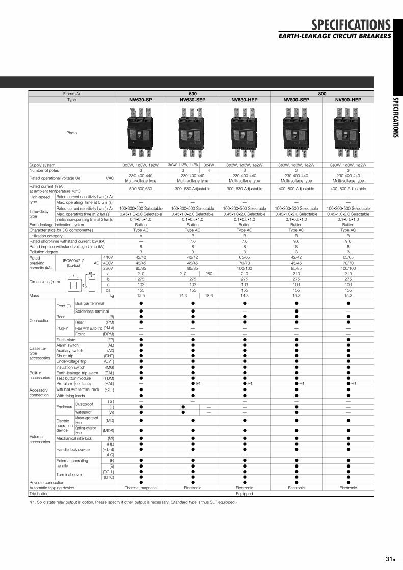
42/42 (36/36) ✳ 145/45 (36/36) ✳ 185/85 (65/65) ✳ 1
42/42 (36/36) ✳ 145/45 (36/36) ✳ 185/85 (65/65) ✳ 1
✳✳ 2. Solid state relay output is option. Please specify if other output is necessary. (Standard type is thus SLT equipped.)
In case of solderless terminal, interrupting capacity reduces as follows..1
ELCBS NV-S Series (Standard type )
a
b
cac
31
SPECIFICATIONS
SPECIFICATIONSEARTH-LEAKAGE CIRCUIT BREAKERS
)A(emarF 036 008epyT PS-036VN PES-036VN PEH-036VN PES-008VN PEH-008VN
otohP
metsysylppuS W2ø1,W3ø1,W3ø3 W2ø1,W3ø1,W3ø3 W4ø3 W2ø1,W3ø1,W3ø3 W2ø1,W3ø1,W3ø3 W2ø1,W3ø1,W3ø3selopforebmuN 3 3 4 3 3 3
eUegatlovlanoitarepodetaR CAV044-004-032
epytegatlov-itluM044-004-032
epytegatlov-itluM044-004-032
epytegatlov-itluM044-004-032
epytegatlov-itluM044-004-032
epytegatlov-itluM)A(nItnerrucdetaR
04erutarepmettneibmata °C 036,006,005 elbatsujdA036~003 elbatsujdA036~003 elbatsujdA008~004 elbatsujdA008~004
deeps-hgiHepyt
IytivitisnestnerrucdetaR ∆ )Am(n — — — — —I5taemitgnitarepo.xaM ∆ )s(n — — — — —
yaled-emiTepyt
IytivitisnestnerrucdetaR ∆ )Am(n 001 • 003 • elbatceleS005 001 • 003 • elbatceleS005 001 • 003 • elbatceleS005 001 • 003 • elbatceleS005 001 • 003 • elbatceleS00554.0 • 0.1 • elbatceleS0.2 54.0 • 0.1 • elbatceleS0.2 54.0 • 0.1 • elbatceleS0.2 54.0 • 0.1 • elbatceleS0.2 54.0 • 0.1 • elbatceleS0.2
0.1•5.0•1.0 0.1•5.0•1.0 0.1•5.0•1.0 0.1•5.0•1.0 0.1•5.0•1.0metsysnoitacidniegakael-htraE nottuB nottuB nottuB nottuB nottuB
setnenopmocCDrofscitsiretcarahC CAepyT CAepyT CAepyT CAepyT CAepyTyrogetacnoitazilitU A B B B B
)Ak(wcItnerrucdnatshtiwemit-trohsdetaR — 6.9 6.9)Vk(pmiUegatlovdnatshtiweslupmidetaR 8 8 8 8 8
eergednoitulloP 3 3 3 3 3detaR
gnikaerb)Ak(yticapac
2-74906CEI)scl/ucl( CA
V044 24/24 24/24 56/56 24/24 56/56V004 54/54 54/54 07/07 54/54 07/07V032 58/58 58/58 001/001 58/58 001/001
)mm(snoisnemiD
a 012 012 082 012 012 012b 572 572 572 572 572c 301 301 301 301 301ac 551 551 551 551 551
Mass gk 5.21 3.41 6.81 3.41 3.51 3.51
noitcennoC
)F(tnorFlanimretsselredloS ●
●
●
●
— ● —raeR )B( ● ● ●
●
●
●
●
●
ni-gulP
raeR )MP( ● ● ● ● ●
Rear with auto-trip )A-MP( — — — — —
tnorF )MPD( — — — — —etalphsulF )PF( ● ● ● ● ●
-ettessaCepyt
seirossecca
hctiwsmralA )LA( ● ● ● ● ●
hctiwsyrailixuA )XA( ● ● ● ● ●
pirttnuhS )THS( ● ● ● ● ●
pirtegatlovrednU )TVU( ● ● ● ● ●
ni-tliuBseirossecca
hctiwsnoitalusnI )GM( ● ● ● ● ●
mralapirtegakael-htraE )LAE( ● ● ● ● ●
eludomnottubtseT )MBT( ● ● ● ● ●
Pre-alarm (PAL) ● ✳ 1 ● ✳ 1 ● ✳ 1 ● ✳ 1
yrosseccAnoitcennoc
kcolblanimreteriw-daelhtiW )TLS( ● ● ● ● ●
sdaelgniylfhtiW ● ● ● ● ●
lanretxEseirossecca
erusolcnEfoorptsuD
contacts
)S( —
—
— — — —)I( ● ● — — ● —
foorpretaW )W( ● ● — — ● —
cirtcelEnoitarepo
ecived
detarepo-rotoMepyt )DM( ● ● ● ● ●
egrahc-gnirpSepyt )SDM( ● ● ● ● ●
kcolretnilacinahceM )IM( ● ● ● ● ●
ecivedkcoleldnaH)LH( ● ● ● ● ●
)S-LH( ● ● ● ● ●
)CL( — — — — —gnitarepolanretxE
eldnah)F( ● ● ● ● ●
)S( ● ● ●
●
● ●
●revoclanimreT
)L-CT( ● ● ●
)CTB( ● ● ● ● ●
noitcennocesreveR ● ● ● ● ●
ecivedgnippirtcitamotuA citengam,lamrehT cinortcelE cinortcelE cinortceE cinortcelEdeppiuqE
Max. operating time at 2 I∆n (s)Inertial non-operating time at 2 I∆n (s)
7.6 7.6
Bus bar terminal
nottubpirT
✳ 1. Solid state relay output is option. Please specify if other output is necessary. (Standard type is thus SLT equipped.)
a
b
cac
32
SPECIFICATIONS
SPECIFICATIONS
MINIATURE CIRCUIT BREAKERS
epyT HB P-HB
)A(emarF 07 001 001 07 001 001
otohP
selopforebmuN 1 2 3 1 2 3
)A(Rated current04erutarepmettneibmata ° C
Rated voltage (V)CA 230/400
CD 125
IEC608983
3
— 1
230/400
125
1
snoisnemiD)mm(
a 52 05 57 52 05 57
b 59 47
c 5.75 5.06
ac 5.77 97
Mass (kg) 0.16 0.32 0.48 0.13 0.26 0.38
n ✳ 1oitcennoC
lanimretpmalC )daol(pmalC)enil(ni-gulP
ecivedgnippirtcitamotuA citengam,lamrehT
Optionalaccessories
revoclanimreT —
etalpgnitnuoM —
esablanimreT —
revockcoL
ybdevorppA —
—
—
3
3
—
—
KN,LG,RL — — KN,LG,BA,VB,RL —
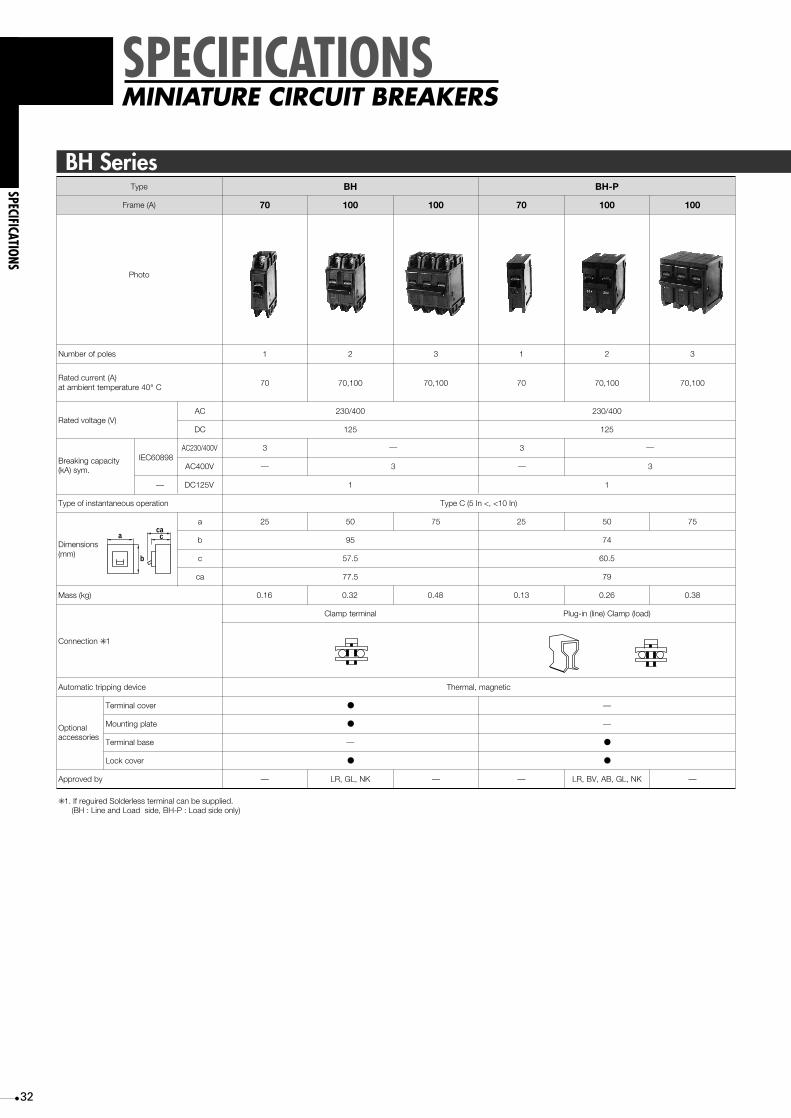
✳ 1. If reguired Solderless terminal can be supplied. (BH : Line and Load side, BH-P : Load side only)
DC125V
AC230/400V
AC400VBreaking capacity(kA) sym.
Type of instantaneous operation Type C (5 In <, <10 In)
●
●
●
●
●
70,10070,10070 70,10070,10070
BH Series
a
b
cac

SPECIFICATIONS
33
SPECIFICATIONSMINIATURE CIRCUIT BREAKERS
epyT 3MS-HB 6MS-HB
otohP
selopforebmuN 1 2 3 1 2 3
)A(tnerrucdetaRat ambient temperature 40°C
,)52(,02,51,01,506,05,04,03
,)52(,02,51,0106,05,04,03
,)52(,02,5106,05,04,03
,)52(,02,51,01,506,05,04,03
,)52(,02,51,0106,05,04,03
,)52(,02,5106,05,04,03
Rated voltage (V)230/400
125
400 400 230/400 400 400
3
— —3
6
6
Type of instantaneous operation B,C,D ✳ 2sepyT
snoisnemiD)mm(
a 52 05 57 52 05 57
b 59 59
c 5.75 5.75
ac 67 67
Mass (kg) 51.0 23.0 05.0 51.0 23.0 05.0
n ✳ 1oitcennoC
lanimretpmalC
ecivedgnippirtcitamotuA citengam,lamrehT
lanoitpOseirossecca
revoclanimreT
etalpgnitnuoM
kcoleldnaH
revockcoL —
ybdevorppA —
✳ 1. If required Solderless terminal can be supplied (Line and Load side)✳ 2. Type B (3 In <, 5 In), Type C (5 In <, 10 In), Type D (10 In <, 20 In)
●
●
●
CA
CD
IEC60898
—
— — 125— —
1—
—
— 1—
—
—DC125V
AC230/400V
AC400VBreaking capacity(kA) sym.
a
b
cac

34
SPECIFICATIONS
SPECIFICATIONS
MINIATURE CIRCUIT BREAKERS
epyT BH-PS M3 BH-PS M9
otohP
selopforebmuN 1 2 3 1 2 3
,02,51,0106,05,04,03
,02,51,0106,05,04,03
,02,5106,05,04,03
,)52(,02,61,01,606,05,04,23
,)52(,02,61,0106,05,04,23
,)52(,02,61,0106,05,04,23
Rated voltage (V)230/400
125
400 400 230/400 400 400
3
3
Type of instantaneous operation B,C,D ✳sepyT
snoisnemiD)mm(
a 52 05 57 52 05 57
b 81.5
c 60.5
ac 79
81.5
60.5
79
Mass (kg) 51.0 23.0 05.0 51.0 23.0 05.0
noitcennoC
pm (load)alC
ecivedgnippirtcitamotuA citengam,lamrehT
lanoitpOseirossecca
revoclanimreT
Terminal base
●
ybdevorppA — LR
—
●
—
CA
CD
IEC60898
—
— — —
1—
—
—
—
9
9
—
—
—DC125V
AC230/400V
AC400VBreaking capacity(kA) sym.
)enil(ni-gulP
kcoleldnaH
revockcoL
)A(tnerrucdetaRat ambient temperature 40°C
✳ Type B (3 In <, 5 In), Type C (5 In <, 10 In), Type D (10 In <, 20 In)
BH Series
a
b
cac

SPECIFICATIONS
35
SPECIFICATIONSDIN SERIES FOR GENERAL
CONSUMER UNITS
MCB 6 (IEC60898)D-HB
otohP
selopforebmuN 1 2 3
)A(tnerrucdetaRat ambient temperature 30°C
,52,02,61,31,01,636,05,04,23
,52,02,61,31,01,636,05,04,23
,52,02,61,31,01,636,05,04,23
)CAV(egatlovdetaR 004/032 004 004
y (kA) sym. (IEC60898)ticapacgnikaerB 6
scitsiretcarahcgnippirT C ✳,BepyT
snoisnemiD)mm(
a 81 63 45
b 78
c 44
ac 07
Mass (kg) 51.0 03.0 54.0
noitcennoC Solderless
ecivedgnippirtcitamotuA citengam,lamrehT
Optional accessories Insulating barrier — cp1 scp2
4
,52,02,61,31,01,636,05,04,23
004
72
0.6
scp3
Isolating switch D (IEC60947-3)-BK
otohP
selopforebmuN 1 2 3
)A(tnerrucdetaRat ambient temperature 30°C 32, 63
)CAV(egatlovdetaR 230 004
Short time withstand current (A) 20 ✕ In, 1s
Short-circuit making capacity (A) 20 ✕ In
snoisnemiD)mm(
a 81 63 45
b 78
c 44
ac 07
Mass (kg) 0.09 0.18 0.27
noitcennoC Solderless
— cp1 scp2
4
72
0.36
scp3
Utilization category AC22A class
Optional accessories Insulating barrier
RCCB D (IEC61008)-VB
otohP
selopforebmuN 2
)A(tnerrucdetaRat ambient temperature 30°C 25, 40, 63
)C 230 230/400AV(egatlovdetaR
Rated current sensitivity I∆n (mA)
Rated conditional short-circuit current (kA)
Pulsating current sensitivity
30, 300
Max. operating time (sec) at 5I∆ 0.04
Type AC
6
snoisnemiD)mm(
a 63
b 58
c 44
ac 07
Mass (kg) 0.2
noitcennoC Solderless
4
72
0.35
✳ Type B (3n�, �5In), Type C (5In�, �10In)
a
b
cac
a
b
cac
a
b
cac

36
SPECIFICATIONS
SPECIFICATIONS
MOTOR PROTECTION
MCCB MB Series
a
b
cac
✳ 1. Rating at 40°C is also available. Please specify when ordering.✳ 2. Bolt terminal.
Frame (A)
Type MB30-SP MB50-CP MB50-SP MB100-SP MB225-SP
Rated ambient temperature, °C ✳ 1 30 30 30 30 30
Number of poles 3 3 3 3 3
Rated insulation voltage Ui (V) AC 500 500 500 500 500
Rated short-circuit breakingcapacity, r.m.s. (kA) as perIEC60947-2 (Icu/Ics)
Ue
500V AC
440V AC
400V AC
230V AC
— — — — —
2.5/1 2.5/1 7.5/4 25/13 25/13
5/2 5/2 7.5/4 30/15 30/15
5/2 5/2 10/5 50/25 50/25
Utilization category A A A A A
Reverse connection ● ● ● ● ●
Rated impulse withstand voltage Uimp (kV) 6 6 6 6 6
Pollution degree 2 2 2 2 2
Dimensions (mm)
a
b
c
ca
75 75 75 90 105
130 130 130 155 165
68 68 68 68 68
90 90 90 90 92
Mass Kg 0.65 0.65 0.75 1.1 1.5
Installationandconnection
Fixed
Plug-in
Front(F)
Screw terminal
Solderless terminal
Bus bar terminal
Rear (B)
Rear (PM)
Rear with auto-trip (PM-A)
Front (DPM)
Flush (FP)
● ● ● ● ● ✳ 2
— — — ● ●
● ● ● ● ●
● ● ● ● ●
● ● ● ● ●
● ● ● ● ●
— — — — ●
● ● ● ● ●
Cassette-typeaccessories
Alarm switch (AL)
Auxiliary switch (AX)
Shunt trip (SHT)
Undervoltage trip (UVT)
● ● ● ● ●
● ● ● ● ●
● ● ● ● ●
● ● ● ● ●
Accessoryconnections
With lead-wire terminal block (SLT)
With flying lead
Built-inaccessories
Pre-alarm contact output (PAL)
● ● ● ● ●
● ● ● ● ●
— — — — —
Externalaccessories
EnclosureDustproof
(S)
(I)
Waterproof (W)
Handle lockdevice
Handle lock(HL)
(HL-S)
(LC)Lock cover
ExternalOperatinghandle
Insulatingbarrier
Door mounting
(V)
(S)
(SS)
(R)
(F)Mounted onbreaker
● ● ● ● ●
● ● ● ● ●
● ● ● ● ●
Electrical operation device (MD) — — — ● ●
Mechanical interlock (MI) ● ● ● ● ●
● ● ● ● ●
● ● ● ● ●
● ● ● ● ●
— — — ● ●
● ● ● ● ●
● ● ● ● —
— — — ● ●
● ● ● ● ●
Between phase (BA-F)
To ground (BA-G)
Large (TC-L)
Small (TC-S)
Transparent (TTC)
For rear connection (BTC)
For plug-in (PTC)
Adapter for IEC 35mm rail
● ● ● ● ●
● ● ● ● ●
● ● ● ● ●
● ● ● ● ●
● ● ● ● ●
● ● ● ● ●
● ● ● ● ●
● ● ● ● —
Marine approval (NK, etc.) ● ● ● ● ●
Automatic tripping device Hydraulic-magnetic Hydraulic-magnetic Hydraulic-magnetic Thermal, magnetic Themal, magnetic
Trip button Equipped
Rated current (In), A
0.8, 1.2, 1.4 ,2, 2.5, 4, 5,7.1, 8, 10,
12, 16, 25, 32
0.8, 1.2, 1.4 ,2, 2.5, 4, 5,7.1, 8, 10,
12, 16, 25, 32,40, 45
0.8, 1.2, 1.4 ,2, 2.5, 4, 5,7.1, 8, 10,
12, 16, 25, 32,40, 45
12.5, 16, 25,32, 40, 45,63, 71, 90,
100
125, 150,175, 200,
225
30
Terminalcover
50 100 225

SPECIFICATIONS
37
noitcetorptluaF sgnidniwrotomfognitaehrevodnatiucrictrohs,daolrevo,egakael-htraE
)A(emarF 03 05 001 522
epyT SC-03NM PC-05NM PS-05NM PS-001NM PS-522NM
seriwdnaesahP 3 3ø 1;w w2ø 3 3ø w
selopforebmuN 3 3 3 3 3
)CAV(egatlovdetaR 002-001 514-042-021
)A(gnitarerepmA04erutarepmettneibmata ° C
ehtfosrotomEssalcroF)Wk(stuptuognidnopserroc
deeps-hgiHepyt
)Am(ytivitisnestnerrucdetaR 001,03,51 001,03 • 002 • )elbatceleS(005
)s(emitgnitarepo.xaM 1.0
metsysnoitacidniegakael-htraE nottuB
)Ak(yticapacgnitpurretnI1738CSIJ
V514 — 5.2 5.7 52 52
V042 )V002(5.2 5 01 05 05
V021 )V001(5.2 5 01 05 05
snoisnemiD )mm(
a 5.76 57 57 09 501
b 69 031 031 551 561
c 25 86 86 86 86
ac 76 09 09 09 29
Mass )gk( 4.0 7.0 7.0 2.1 7.1
noitcennoC lanimretpmalC lanimretwercS
seirosseccA
hctiwsmralA )LA( ● ● ● ● ●
hctiwsyrailixuA )XA( ● ● ● ● ●
hctiwsnoitalusnI )GM( ● ● ● ● ●
seriwdaelnottubtseT )LBT( ● ● ● ● ●
mralaegakael-htraE )LAE( — ● ✳ 2 ● ✳ 2 ● ✳ 2 ● ✳ 2
● ✳ 2 ● ✳ 2 ● ✳ 2 ● ✳ 2eludomnottub-tseT )MBT( —
kcolblanimreteriw-daeL TLS ● ● ● ● ●
ecivednoitarepolacirtcelE )DM( — — — ● ●
kcolretnilacinahceM )IM( — ● ● ● ●
erusolcnEfoorptsuD
)S( ● ● ● ● ●
)I( — ● ● ● ●
foorpretaW )W( — ● ● ● ●
ecivedkcoleldnaH )LH( — ● ● ● ●
revockcoL )CL( ● ● ● ● ●
eldnahlanretxEF — ● ● ● ●
S — ● ● ● ●
revoclanimreT )LCT( ● ● ● ● ●
dutsraeR ● ● ● ● ●
emarfgnitnuom-hsulF — ● ● ● ●
lanimretni-gulP — ● ● ● ●
)noitpO(CEIotnoitamrofnoC — — — — —
ecivedgnippirtcitamotuA citengam-ciluardyH citengam,lamrehT
✳ 1
✳ If using a 3-pde earth-leakage breaker as a 1-pde 2-phase device, connect the left and right poles and not the central pde..1✳ Lead-wire terminal block is equipped..2
ELCB MN Series
AWk
V001 V002
23 — 5.7
52 — 5.5
61 57.0 7.3
01 4.0 2.2
1.7 — 5.1
3.6 2.0 —
4 1.0 57.0
5.2 — 4.0
4.1 — 2.0
AWk
AWk
V002 V514 V002 V514
54 11 22 8 — 7.3
04 — 5.81 1.7 5.1 —
23 5.7 51 5 — 2.2
52 5.5 11 4 57.0 5.1
61 7.3 5.7 5.2 4.0 —
21 — 5.5 2 — 57.0
01 2.2 — 4.1 2.0 —
AWk
AWk
V002 V514 V002 V514
54 11 22 1.7 5.1 —
04 — 5.81 5 — 2.2
23 5.7 51 4 57.0 5.1
52 5.5 11 5.2 4.0 —
61 7.3 5.7 2 — 57.0
21 — 5.5 4.1 2.0 —
01 2.2 — 2.1 — 4.0
8 — 7.3 8.0 — —
AWk
V002 V514
001 — 55
09 22 54
17 5.81 73
36 51 03
54 11 22
AWk
V002 V514
522 55 01
002 — —
571 54 09
051 73 57
521 03 —
a
b
cac
SPECIFICATIONSMOTOR PROTECTION
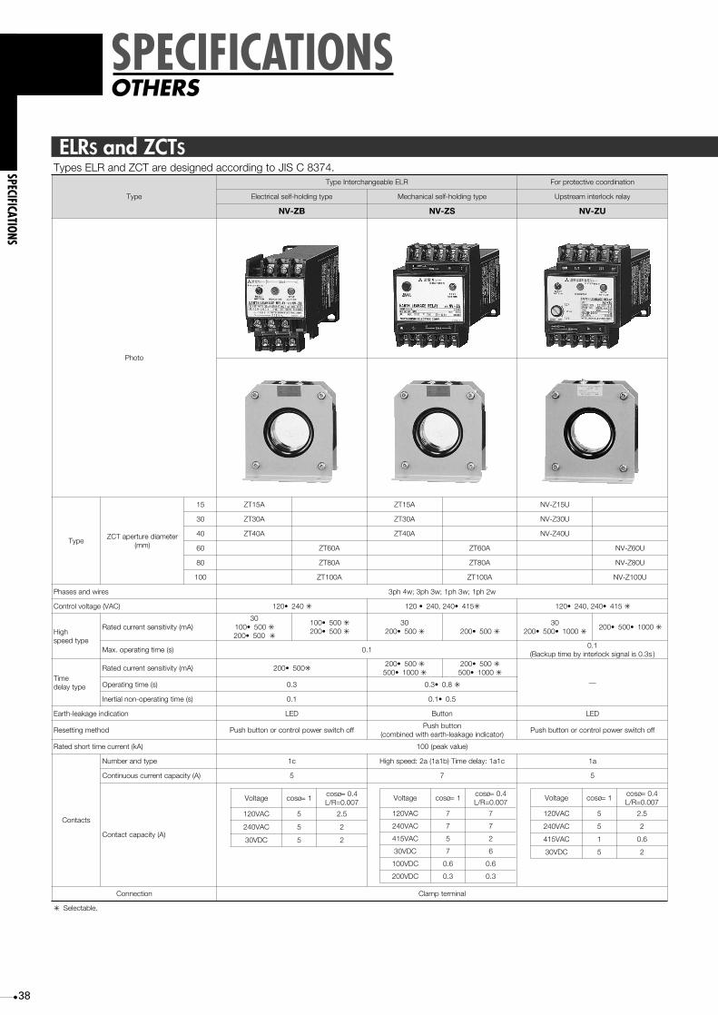
38
SPECIFICATIONS
SPECIFICATIONS
OTHERS
.4738CSIJotgnidroccadengisederaTCZdnaRLEsepyT
epyT
RLEelbaegnahcretnIepyT noitanidroocevitcetorproF
epytgnidloh-fleslacirtcelE epytgnidloh-fleslacinahceM yalerkcolretnimaertspU
BZ-VN SZ-VN UZ-VN
otohP
epyTretemaiderutrepaTCZ
)mm(
51 A51TZ A51TZ U51Z-VN
03 A03TZ A03TZ U03Z-VN
04 A04TZ A04TZ U04Z-VN
06 A06TZ A06TZ U06Z-VN
08 A08TZ A08TZ U08Z-VN
001 A001TZ A001TZ U001Z-VN
Phases and wires w2hp1;w3hp1;w3hp3;w4hp3
Control voltage (VAC) 042•021 ✳ 514•042,042•021 ✳ 514•042,042•021 ✳
hgiHepytdeeps
)Am(ytivitisnestnerrucdetaR03
005•001 ✳005•002 ✳
005•001 ✳005•002 ✳
03005•002 ✳ 005•002 ✳
030001•005•002 ✳
0001•005•002 ✳
)s(emitgnitarepo.xaM 1.01.0
)s3.0silangiskcolretniybemitpukcaB(
emiTepytyaled
)Am(ytivitisnestnerrucdetaR 005•002 ✳005•002 ✳0001•005 ✳
005•002 ✳0001•005 ✳
—)s(emitgnitarepO 3.0 8.0•3.0 ✳
)s(emitgnitarepo-nonlaitrenI 1.0 5.0•1.0
noitacidniegakael-htraE DEL nottuB DEL
dohtemgnitteseR ffohctiwsrewoplortnocronottubhsuPnottubhsuP
)rotacidniegakael-htraehtiwdenibmoc(ffohctiwsrewoplortnocronottubhsuP
Rated short time current (kA) )eulavkaep(001
stcatnoC
epytdnarebmuN c1 c1a1:yaledemiT)b1a1(a2:deepshgiH a1
)A(yticapactnerrucsuounitnoC 5 7 5
)A(yticapactcatnoC
noitcennoC lanimretpmalC
✳ .elbatceleS
ELRS and ZCTS
egatloV soc =ø 1soc =ø 4.0
700.0=R/L
CAV021 5 5.2
CAV042 5 2
CDV03 5 2
egatloV soc =ø 1soc =ø 4.0
700.0=R/L
CAV021 7 7
CAV042 7 7
CAV514 5 2
CDV03 7 6
CDV001 6.0 6.0
CDV002 3.0 3.0
egatloV soc =ø 1soc =ø 4.0
700.0=R/L
CAV021 5 5.2
CAV042 5 2
CAV514 1 6.0
CDV03 5 2

SPECIFICATIONS
39
SPECIFICATIONSOTHERS
epyT A51TZ A03TZ A04TZ A06TZ A08TZ A001TZ
)mm(retemaiderutrepA 51 03 04 06 08 001
Mass (kg) 2.0 4.0 6.0 0.2 6.2 3.3
Rated short time current )eulavkaep(001
)mm(snoisnemiD a 84 86 58 041 061 581
b 25 25 25 09 09 09
c 07 09 001 051 961 091
d 52 05 05 001 001 001
e 04 04 04 07 07 07
)mm(retemaiderutrepaTCZ51 03 04 06 08 001
mmnieziseriwdetarV006elbissimrep.xaM 2 )serepmanitnerruc(
w2ø1 eriwdetalusniedirolhclynivyloP )88(41 )712(06 )593(051 )056(523 )299(006 )5811(008
elbacdetalusnienelyhteylopdeknil-ssorC )33(2 )091(83 )062(06 )556(052 )078(004 )0411(006
w3ø1w3ø3
eriwdetalusniedirolhc-lynivyloP )16(8 )261(83 )892(001 )655(052 )248(005 )5901(527
elbacdetalusnienelyhteylopdeknil-ssorC )33(2 )531(22 )062(06 )065(002 )067(523 )0411(006
w4ø3 eriwdetalusniedirolhc-lynivyloP )16(8 )261(83 )892(001 )593(051 )056(523 )299(006
elbacdetalusnienelyhteylopdeknil-ssorC — )501(41 )091(83 )563(001 )556(052 )078(004
epyT A006ATZ A0021ATZ A0002ATZ
selopforebmuN 3
)CAV(egatlovdetaR 006
Rated short time current (kA) )eulavkaep(001
a 722 722 063
b 652 892 052
ab 663 444 495
c 24 87 97
ac 521 671 412
)A(emarF 006 0021 0002 0023
epyT
BZsrotcudnocyramirphtiwsTCZelbaegnahcretnidnaRLEelbaegnahcretnI
0023BZ-VN
SZ 0023SZ-VN
UZ 006UZ-VN 0021UZ-VN 0002UZ-VN 0023UZ-VN
selopforebmuN 3
)CAV(egatlovdetaR 006
Rated short time current (kA) )eulavkaep(001
a 722 722 063 094
b 652 892 052 023
ab 663 444 495 868
c 24 87 97 111
ac 521 671 412 092
Mass (kg) 5.6 11 72 45
fonoitacificepSsRLE
epytdeeps-hgiH
)CAV(egatlovlortnoC )Am(ytivitisnestnerrucdetaR )s(emitgnitarepo.xaM )s(emitgnitarepo-nonlaitrenI
BZ 021 • 042 ✳ 002 • 005 ✳1.0 —
SZ 021 • 042,0✳42
021 • 0✳42
021 • 0✳42
• 514 ✳ 002 • 005 ✳
UZ 042, • 514 ✳ 002 • 005 • 0001 ✳1.0
kcolretniybemitpukcab()s3.0silangis
—
epytyaled-emiTBZ 021 • 042 ✳ 002 • 005 ✳ 3.0 1.0
SZ 042, • 514 ✳ 002 • 005 ✳ 3.0 • 8.0 ✳ 1.0 • 5.0 ✳
✳ .elbatceleS
● ELRs with a ZCT with primary conductors
● Interchangeable ZCTs with primary conductors
● ZCT aperture diameter and permissible wire size
● Interchangeable ZCT
da
be
c
a
ca
c
bab
a
ca
c
bab

40
SPECIFICATIONS
SPECIFICATIONS
OTHERS
)A(emarF 03
epyT AB03 -PC B-PC S-PC
otohP
selopforebmuN 1 2 3 1 2 3 1 2 3
)V(egatlovdetaR
Rated impulse voltage Uimp (kV)
052CA56CD
052CADC 125 052CA
052CA)ylnoepytseiressrekaerbelop-2rof(521CD,56CD ✳ 1
esunommocCD-CA
)A(tnerrucdetaR 03,02,51,01,7,5,3,2,1,5.0,3.0,52.0,1.0,57.0,5.0,3.0,52.0,1.0,50.0,51,01,5.7,7,5,3,5.2,2,1
03,52,02
gnitpurretnI)A(yticapac
CA
V521 —
2.5 2.5 2.5
0052 0052
V042 0052 — —
V052 — 0051 0051
CDV06 0052 — — )V56CD(0001 )V56CD(0001
V021 — 0052 — — 1000 (DC125V) 1000 (DC125V)— — —
scitsiretcarahcgnitarepO)I(epytsuoenatnatsnI), (MD)M(epytdeeps-muideM ), (FD)F(epyttsaF)I(epytsuoenatnatsnI
), (SD)S(epytwolS), (MD)M(epytdeeps-muideM
metsysgnippirTmagnetic only:)I(epytsuoenatnatsnI
, MD, F, FD, S, SD): hydraulic magneticM(sepytrehtOmagnetic only:)I(epytsuoenatnatsnI
MD, S): hydraulic magnetic,M(sepytrehtO
(erutarepmettneibmadradnatS ° )C 04 04 52
Mass g 08 061 032 001 002 003 06 021 081
seirosseccA
)DI(yaledlaitrenI ● )ylnoCA:deeps-muideM( ● )ylnoCA:wols,tsaf,deeps-muideM(
)LA(hctiwsmralA ● )cI( ● )bIroaI( ✳ 2 ✳ 2● )cI(
)XA(hctiwsyrailixuA ● )cI( ● )bIroaI( ● )cI(
)THS(pirttnuhS — ● )ylnoepytyalerrof( ● )epytyalerdnalellaraprof(
)CL(revockcoL — ● — ● —
revoclanimreT
Accessory terminal covor
● ✳ 4
●
— —
— —
Back facing wiring terminal ● ✳ 3 — —
noitcennoCydobniaM
Screw terminal M4:sselroA02Screw terminal M5:A03
Screw terminal M5 052#lanimretnetsaF
hctiwsyrailixuA/hctiwsmralA Screw terminal M3.5 Screw terminal M3.5 011#lanimretnetsaF
dohtemgnitnuomydobniaMgnitnuomliarIEC,ecafruS
)noitpo(gnitnuomlenaphsulFgnitnuomliarIEC,ecafruS
On end contact fuse interchangeable metal (option)gnitnuomlenaP
)KN(lavorppaeniraM — ✳● 5 — —
dradnatslanoitanretnI ASC,LU — LU ✳ 6 —
gnikramEC ✳● 5 —
✳● 6
✳ 1 g.niredronehwesuCDroffiyficepS.✳ 2 . .elbaliavasiV56CDylno,esuCDfoesacnI✳ 3 . In case of back facing wiring terminals, specify if it will be used with ratings 20A or less, or 30A.
(with insulation cap).✳ 4 . The terminal cover is used for protection of electric shock (IPIX) caused by an intended contact from front direction,
with insulation cable lugs (or taping the tube of cable lugs) or direct clamp of the conductor.✳ 5 . Specify when ordering.✳ 6 . Specify when ordering. (In case of CP-S UL, type name is CP-SU.) Connection is fasten terminal only.
Slow type (S)
(Screw terminal M4 series type only )
Operating characteristics isMedium-speed type(M) only.The rated current, 0.3A,2A, 3A and 7A are not applied.
CIRCUIT PROTECTORS TYPE CP

41
SPECIAL PURPOSE BREAKERSMAG ONLY, DC-USE AND DSN-TYPE
Mag Only (Instantaneous tripping circuit breakers)
dexiF
PH/PC-05FN CD,CA
01xtnerrucdetaR
PH/PC-06FN CD,CA
PH/PS/PC-001FN CD,CA
PH/PS-061FN CD,CA
PH/PS/PC-052FN CD,CA
PS/PC-004FNPC-036FN
NF1000-SS, NF1250-SS AC
NF1600-SS AC
NF1000-SSD, NF1250-SSD DCNF1600-SSD
CD,CA
elbatsujdA
PS-036FN CD,CA01xtnerrucdetaR:hgiH
4xtnerrucdetaR:woL
PES-008FN CA01xtnerrucdetaR:hgiH
2xtnerrucdetaR:woL
PDS-008FN CD A0008:hgiH
High: Rated current x10Low: Rated current x5
High: Rated current x6Low: Rated current x3
High: 8000ALow: 3200A
A0023:woL
Note: Standard are fixed type models. Adjustable type can be made to order.Remarks: 1. The size, weight, accessories, etc., are all identical to the same-designation C
and S series breakers.2. For more detail, contact your dealer.
SPECIAL PURPOSE BREAKERS
DC-Use MCCBs and DSN-type SwitchesBreaking is more difficult with direct currents becausethe current value never reaches zero. While ordinaryDC breakers are suitable for low voltages, specialvoltage DC breakers are recommended for voltages inexcess of 250VDC. Breakers for 550V are all 4-polemodels.The size, shape, drilling plan, accessories, etc., are allidentical to the S series of same-designation breakers.
epyTselopforebmuN
)CDV(egatlovdetaR)Ak(yticapacgnikaerbdetaR
)SCI/UCI(2-74906CEI
NF50-HP NF60-HP NF100-SP NF160-SP NF250-SP NF400-SP NF630-SP NF800-SDP NF1000-SSD NF1250-SSD NF1600-SSD3
4004
5503
4004
5503
4404
5503
4404
5503
4404
5503
4404
5503
4404
5503
4404
5503
4404
5503
4404
5503
4404
550
2/1 2/1 10/5 15/8 15/8 40/40 40/40 40/40 40 40 40
Notes: 1: Time constant: 10ms or below.
• DC sideThese breakers are designed as thyristor-Leonardsystem DC-side breakers. They protect the thyristorfrom short circuiting when there is a power or
communication failure. (Mag-Only breakers can alsobe used for this role.) Use these breakers incombination with fast fuses for even greater protection.
• DSN-type switchesThese are standard MCCBs without the automatictripping element. The tripping capacity is about sixtimes the rated current.
The appearance, size, drilling plan and availableaccessories are all identical to similar type standard Sand C series MCCBs.
Note: The tripping characteristics will change if the wiring differs from the oneshown here.
Wiring diagram for DC use.
epyTselopforebmuN
)CDV(egatlovdetaR)Ak(yticapacgnitpurretnI
).nim(tnerrucpirtsuoenatnatsnI
NF100-SP NF160-SP NF250-SP NF400-SP NF630-SP NF800-SDP NF1000-SSD NF1250-SSD NF1600-SSD2
25015
2250
3440
344010
3 times rated current 700A
20
2250
3440
700A
20
2250
3440
900A
20
2250
3440
1000A
20
2250
3440
1400A
20
2250
3440
2000A
20
2250
3440
2500A
20
2250
3440
3200A
20
Wiring diagram for DC-usage.
epyT SC-03NSD PC-05NSD PC-001NSD PC-052NSD PC-004NSD PC-036NSD PC-008NSD)A(tnerrucdetaR 03 05 001 052 004 036 008
selopforebmuN 2 3 2 3 2 3 2 3 2 3 3 3)CD/CA(egatlovdetaR —/064 052/005 052/005 052/005 052/006 052/006 052/006
—/081 521/003 052/006 065/0531 0001/0042 5751/0873 0002/0084)CD/CA(tnerrucgnihctiws.xaM
epyT)A(tnerrucdetaR
selopforebmuN
)CD/CA(egatlovdetaR
)CD/CA(tnerrucgnihctiws.xaM
DSN30-SP DSN50-SS DSN50-HP DSN100-SP DSN250-SP DSN400-SP DSN630-SP DSN800-SP DSN1000-SS DSN1250-SS DSN1600-SS30 100
2 3
500/250
180/75 600/250
501
265/125 500/250 500/250
300/125
2 3 4 2 3 4250
1350/560
500/250
2 3 4400
2400/1000
690/250
2 3 4 3 4 3 4 3 4 3 4 3 4630
3780/1575
690/250
800
4800/2000
690/250 440 550 440 550 440 550
1000
2500
1250
3125
1600
4000

42
Generator-Protection MCCBs
epyT NF100-SEP
selopforebmuN 3 3 3 3
)A(tnerrucdetaR
(15~20)30~50,60~100
adjustable
125~250adjustable
125~250adjustable
(15~20)30~50,60~100
adjustable
)tnerrucdetarfo%(pirtsuoenatnatsnI 300
18~28
✳ 1
✳ 1
690
)s(tnerrucdetarfo%051taemitgnitarepO
)V(egatlovnoitalusnidetaR
gnikaerbdetaRyticapac
)Ak(
2-74906CEI)SCI/UCI(
V096CA —
15/8
25/13
30/15
50/25
15/8
25/13
30/15
50/25
30/15
50/25
50/25
100/50
5/3
30/8
50/13
50/13
100/25
5/3—
V005CA
V044CA
V004CA
V032CA
NF100-HEP NF250-SEP NF250-HEP
These breakers are designed for generator protection.
• Specifications
✳ 1: These MCCBs operating characteristic must be adjusted as follows.STD ≤ 3 (Is setting)LTD: minimum setting (TL = 12sec setting)
SPECIAL PURPOSE BREAKERS
400Hz-Use MCCBs
Low-Instantaneous MCCBs
epyT
)A(tnerrucdetaR
selopforebmuN)CDV(egatlovnoitalusnidetaR
yticapacgnikaerbdetaR)Ak(
)SCI/UCI(2-74906CEI
690VV005V044V004V032
NF100-SP NF100-HP NF250-SP NF250-SEP NF250-HP NF400-SP NF400-SEP NF630-SP*1 NF630-SEP NF800-SEP NF1250-SS NF1600-SS
15, 20, 30,40, 50, 60,
75, 100
15, 20, 30,40, 50, 60,
75, 100
125, 150175, 200
125, 150175, 200
225, 250300, 350
125, 150175, 200adjustable
200~350adjustable
300~500adjustable
400~600adjustable400, 500 600-700-800 800-1000-1200
2 3 4 2 3 4 2 3 4 3 4 3 4 3 4 3 4 3 4 3 4 3 42 3 4 2 3 4
15/825/1330/1550/25
15/825/1330/1550/25
15/825/1330/1550/25
5/330/1550/2550/25100/50
5/330/850/1350/13100/25
10/1030/3042/4245/4585/85
10/1030/3042/4245/4585/85
10/1030/3042/4245/4585/85
10/1030/3042/4245/4585/85
10/1030/3042/4245/4585/85
25/1365/3385/4385/43125/63
25/1365/3385/4385/43125/63
690
The tripping characteristics for these MCCBs increasewith an increase in the interrupted currentinstantaneous trip operating current. For this reason,these breakers are recommended for use in high-frequency circuits.
• SpecificationsThe appearance, size, rated interrupting capacity,drilling plan, accessories, etc., are all identical to thestandard S series of same-designation breakers.
• Low-Inst. MCCBs for DiscriminationWhen a power fuse (PF) is used for high-voltageproection, make sure that the MCCB on the secondaryside is compatible.
epyT PC-001FN PS-001FN PC-052FN PS-052FN PC-004FN
selopforebmuN 2 3 2 3 4 2 3 2 3 4 2 3
)A(tnerrucdetaR,57,06,05
00104,03,02,51001,57,06,05
571,051,521052,522,002
571,051,521052,522,002
003,052004,053
pirtsuoenatnatsnIdetarfo%(
)tnerruc
006 ● ● ● ● ●
004 — — ● ● ●
Remarks: 1. Ensure compatibility with motor, etc., before use to prevent accidental tripping at start up.2. Specify rated current and tripping characteristic.3. There are no short time delay characteristics.
The appearance, size, rated interrupting capacity,accessories, etc., are all identical to the standardinstantaneous trip breakers of the same designation.
PF
Tr1
MCCB 1
MCCB 2
Tim
e
Current
Low-inst. MCCBs
MCCBoperatingcharacteristiccurve
PF short-time tolerance capacity
Fig. 4.12 Low-inst. MCCB characteristics
• Specifications
SPECIAL PURPOSE BREAKERS
400HZ-USE, INSTANTANEOUS AND GENERATOR PROTECTION
Note *1. Instantaneous trip current : Rated current x 14 (Fix)

43
CONNECTION
Connection TypesIf no connection method is specified with the order, wedeliver the standard fixed-installation type with frontconnection.
• Connection TypesnoitallatsnI dexiF hsulF ni-gulPnoitcennoC )F(tnorF )B(raeR )PF(raeR )MPD(tnorF )MP(raeR
ecnaraeppA
• Connection AccessoriesepyT )TS-B(sdutsraeR )PF(hsulF )MP(ni-gulP
PH/PC-06FN,PH/PC-05FN,PS-03FNP2 2PS50-TS 2PS50-PF 2PS50-MP
P3
3PS50-TS 3PS50-PF 3PS50-MPPS/PC-05NM,PS/PC-05BM,PS-03BM P3
PH-06VN,PH-05VN,PC-06VN,PC-05VN P3
PH-06FN,PH-05FN P4 4PS50-TS 4PS50-PF 4PS50-MP
PS/PC-001FN P2 2PS1-TS 2PS1-PF 2PS1-MP
A/TPH-001FN,A/TPS-001FN,A/TPC-001FN,PH-001FN,PRH-05FN P2 2PH1-TS 2PH1-PF 2PH1-MP,PS-001BM,PES-001VN,PS/PC-001VN,PES-001FN,PS/PC-001FN
A/TPH-001FN,A/TPS-001FN,A/TPC-001FN,PS-001NMP3 3PS1-TS 3PS1-PF 3PS1-MP
PEH-001VN,PH-001VN,PEH-001FN,PH-001FN,PRH-05FN P3 3PS1-TS 3PH1-PF 3PS1-MP
,A/TPS-001FN,PES-001VN,PES-001FN,PS-001FN P4 4PS1-TS 4PS1-PF 4PS1-MP
PEH-001VN,A/TPH-001FN,PEH-001FN,PH-001FN P4 4PS1-TS 4PH1-PF 4PS1-MP
PU-001FN,PR-001FN P2 2PH1-TS 2PU1-PF 2PU1-MP
PU-001FN,PR-001FN P3 3PS1-TS 3PU1-PF 3PU1-MP
PU-001FN P4 4PS1-TS 4PU1-PF —
A/TPS-052FN,A/TPS-061FN,A/TPC-052FN,PS-061FN,PS/PC-052FN P22PS2-TS
2PS2-PF2PS2-MP
A/TPH-052FN,A/TPH-061FN,PH-052FN,PH-061FN P2 2PH2-PF,PS-522BM,PES-522VN,PS/PC-522VN,PES-052FN,PS/PC-052FN
A/T-061FN,PS-061FN,A/TPS-052FN,A/TPC-052FN,PS-522NMP3
3PS2-TS3PS2-PF
3PS2-MP,PH-061FN,PEH-522VN,PH-522VN,PEH-052FN,PH-052FNA/TPH-061FN,A/TPH-052FN
P3 3PH2-PF
,A/TPS-061FN,PS-061FN,PES-522VN,PES-052FN,PS-052FNA/TPS-052FN
P44PS2-TS
4PS2-PF4PS2-MP,A/TPH-052FN,PH-061FN,PEH-522VN,PEH-052FN,PH-052FN
A/TPH-061FNP4 4PH2-PF
PU-522FN,PR-522FN P2 2PS2-TS 2PU2-PF 2PS2-MP
PU-522FN,PR-522FN P3 3PS2-TS 3PU2-PF 3PS2-MP
4PS2-MPPU-522FN P4 4PS2-TS 4PU2-PF -
PS/PC-004FN P2 2PS4-TS3PS4-PF
2PS4-MP
PES/PS/PC-004VN,PES/PS/PC-004FN P33PS4-TS 3PS4-MP
PER/PEH-004VN,PER/PEH-004FN P3 3PH4-PF
PES-004VN,PES/PS-004FN P44PS4-TS
4PS4-PF4PS4-MP
PEH-004FN P4 4PH4-PF
PS/PC-036FN P2 2PS6-TS3PS6-PF
2PS6-MP
PES/PS/PC-036VN,PES/PS/PC-036FN P33PS6-TS 3PS6-MP
PEH-036VN,PER/PEH-036FN P3 3PH6-PF
PES-036VN,PES/PS-036FN P44PS6-TS
4PS6-PF4PS6-MP
PEH-036FN P4 4PH6-PF
FP-10SS3
FP-10SS4
FP-10SSD3
FP-10SSD4
PDS-008FN P2 2PS8-MP
PES-008VN,PES/PEC-008FN P33PS8-MP
PEH-008VN,PER/PEH-008FN P3
PES-008FN P44PS8-MP
PEH-008FN
NF1000-SS, NF1250-SS
NF1000-SS, NF1250-SS
NF1000-SSD, NF1250-SSD
NF1000-SSD, NF1250-SSD
P4
3P
4P
2P, 3P
4P
—
—
ST-6SP2
ST-6SP3
ST-6SP4
FP-6SP3
FP-6SP4
FP-6HP3
FP-6HP4
—
—
—
—
—
—
CONNECTIONTYPES AND ACCESSORIES
The front-connection model can be modified to othertypes (excluding plug-in) with special purchaseoptions.
Load
LineLoad
Line
Line and load must be connected as shown in figure (a). For MCCBs, line and load may also be connected in reverse as shown in figure (b).
Normal and reverse connection methods
Normal connection (a) Reverse connection (b)

44
ACCESSORIESINTERNAL
Cassette-Type Internal Accessories
Built-In Internal Accessories
ACCESSORIES
seirosseccalanretnI noitcnuF sledomelbacilppAepytnoitcennoC
lanimreteriw-daeLkcolb
sdaelgniylF
)hctiwsmralA(LA .deppirtsahrekaerbehttahtsetacidnIseiresBMdnaS/C-VN,U/S/C-FN
● ●
)hctiwsyrailixuA(XA .FFOroNOsirekaerbehtrehtehwsetacidnI ● ●
)pirttnuhS(THSot%07siegatlovgnippirtelbawollA.etomerybyllacirtcelerekaerbehtspirTBMdnaS/C-VN,U/S/C-FN.CDdnaCAhtobrofegatlovdetarehtfo%011
seires dnaS/C-VN,U/S/C-FNseiresBM
)052~03FN(●
)052~03FN(●
)008~004VN/FN(●
)008~004VN/FN(●
)pirtegatlovrednU(TVUsiegatlovgnippirtehT.spordegatlovehtnehwyllacitamotuarekaerbehtspirT
ehtfo%58otsrevoceregatlovehtnehW.egatlovdetarTVUehtfo%07ot%53.desolcrekaerbehtdnateserebnacTVUeht,evobaroegatlovdetar
)052~03FN(●
—)008~004VN/FN(●
seirosseccalanretnI noitcnuF sledomelbacilppAepytnoitcennoC
lanimreteriw-daeLkcolb sdaelgniylF
)hctiwsmralaegakael-htraE(LAE.egakaelhtraeybdeppirtneebsahrekaerbehttahtsetacidnI
).kcolblanimreteriw-daelhtiwelbaliavaylnO(
seiresNMdnaU/S/C-VN
●
)522~03VN(—
)008~004VN(●
)eludomnottubtseT(MBT .etomerybegatlovtsetaseilppA ● —
)hctiwsnoitalusnI(GMedisdaolehtswollati,rekaerbtiucricegakael-htraenanodellatsninehW
.ffosirekaerbehtelihwderusaemebotecnatsisernoitalusni ● —
)eludommrala-erP(LAP .tnerrucgnittesmrala-erpehtsdeecxetnerrucdaolehttahtsetacidnI
sepyTcinortcelE
● —
)hctiwsmralapirttnerrucrevO(LAOtiucric-trohsrotnerrucrevoybdeppirtneebsahrekaerbehttahtsetacidnI
.tnerruc
—
PES-008~004VN/FN●
Remark: Cassette-type accessories are field-mountable type. They are available for individual purchase.
Switching Operation
Micro-switchused
AC
S
460
250
125
460
250
125
460
250
125
250
125
30
250
125
30
250
125
30
0.2
0.4
4
0.3
0.6
10
5
10
10
0.2
0.4
3
0.3
0.6
6
3
6
10
—
3
5
5
10
10
5
10
10
—
2
3
2
10
10
2.5
10
10
X*1
V
Voltage (V) Resistiveload
Inductiveload
Resistiveload
Inductiveload
Voltage (V)
Amps (A) Amps (A)
DC
NOTE: *1. When DC use polarity must be considered.
● AL, AX Switch Capacities● Earth-Leakage Alarm (EAL) Operation
Main ELCB conditions
Overcurrent, short circuittrip or on or off
EALa (open)
EALc
EALa (open)EALb (closed)EALc
Ground-fault trip
225A frame or less
400A frame or more
225A frame or less
400A frame or more
Earth-leakage alarm contacts
EALa (closed)EALb (open)EALc
EALa (closed)
EALc
● Auxiliary Switch (AX) OperationMain MCCB contacts
Off or tripped
AXa (open)AXb (closed)AXc
On
Auxiliary contacts
*1(DC+)
AXa (closed)AXb (open)AXc
*1(DC+)
● Alarm Switch (AL) OperationMain MCCB contacts
Off or on
ALa (open)ALb (closed)ALc
Tripped
Alarm contacts
*1(DC+)
ALa (closed)ALb (open)ALc
*1(DC+)
● Meggering Switch (MG) Operation
Off or trip
Insulation switch open
On
MG switch closed
Main ELCB conditions MG switch condition

epyT
S/C-FN SC-03FN
U-FN
BM
eloP 3,2 2 4,3,2 4,3
epythctiwS S
seirosseccA
LA
XA
TVUroTHS
✳ 3 ✳ 3 ✳ 3
XA+LA
TVUroTHS+LA
✳ 3 ✳ 3
TVUroTHS+XA
✳ 3 ✳ 3
TVUroTHS+XA+LA
✳ 3 ✳ 3
LAP
✳ 4
NF30-SPNF50-CP/HPNF60-CP/HPNF100-CP/SP
NF30-SPNF50-CP/HPNF60-CP/HPNF100-CP/SP
NF50-HRP NF250-CP/SP/HPNF100-HP NF160-SP/HP
Only 3 pole
NF100-RP/UPNF225-RP/UP
MB30-SPMB50-CP/SPMB100-SPMB225-SP
NF100-SEPNF100-HEPNF250-SEPNF250-HEP
45
ACCESSORIESINTERNAL
Maximum Number of Internally Mounted Accessories
•MCCBS
The number within the circle shows the order of mounting.✳ 1. Only lead-wire type available (LT or SLT is not applicable).✳ 2. UVT mounting requires a UVT voltage module (SHT requires no such voltage module).✳ 3. UVT unavailable.✳ 4. PAL breakers signal an alarm at 70% to 100% of the rated current setting. Control voltage (AC 100-200V) is required.
Left-sidemounting
Right-sidemounting
Handle AL AX
MG EAL TBL PAL
SHT or UVT TI Cassette-type accessories
TBM Lead wire direction
ACCESSORIES
1 2
1 2
1 2
1 2
1 2
1 2
1 2
1 2

46
epyT
S/C-FN
U-FN )P3(PEU-004FN PEU-008FN,PEU-036FN,)P4(PEU-004FN
seloP 4,3,2
epythctiwS S V
seirosseccA
LA
✳ 3
XA
✳ 3
THSroTVU
✳ 1✳ 2
✳ 1 ✳ 2✳ 2
XA+LA
✳ 3 ✳ 3
TVUroTHS+LA
✳ 1✳ 2✳ 3✳ 4
✳ 1✳ 2✳ 3✳ 4
TVUroTHS+XA
✳ 1✳ 2✳ 3✳ 4
✳ 1✳ 2✳ 3✳ 4
TVUroTHS+XA+LA
✳ 1✳ 2✳ 3✳ 4
✳ 1
✳ 2
✳ 2
✳ 2✳ 2✳ 3✳ 4
LAP)tuptuotcatnoc(
✳ 5
PEU/PER/PEH/PES-004FNrofnoitpO
✳ 5
Option for NF630-SEP/HEP/REP/UEPNF800-CEP/SEP/HEP/REP/UEP
Option for NF630-SEP/HEP/REP/UEPNF800-CEP/SEP/HEP/REP/UEP
IT
✳ 6
PEU/PER/PEH/PES-004FNrofnoitpO
✳ 6
.gnitnuomforedroehtswohselcricehtnihtiwrebmunehT✳ .1✳ .)eludomegatlovhcusonseriuqerTHS(eludomegatlovTVUaseriuqergnitnuomTVU.2✳ .yrassecensiTLSredro-laicepsa,XA+LAroXA,LAehtsaelopemasehtotTVUroTHSagnitnuomnehwro,TLSybsecivedgnitnuomelop-tfeleerhtnahteromgnitnuomnehW.3✳ .etarapessieludomegatlovTVUeht,XA+LAro,XA,LAehtsaelopemasehtotTVUagnitnuomnehW.4✳ ).elopthgirs'rekaerbehtotdetnuomebnacseirosseccarehtoon,esacsihtnI(.yrassecensi)V002~001CA(egatlovlortnoC.dradnatssideppiuqe-TLS.5✳ ).elopthgirs'rekaerbehtotdetnuomebnacseirosseccarehtoon,esacsihtnI(.yrassecensi)V002~001CD/V002~001CA(egatlovlortnoC.dradnatssideppiuqe-TLS.6
SHT and UVT are right-pole mounting as standard. Please specify if left-pole mounting is required.
NF400-CP/SPNF400-SEP/HEP/REP
NF630-CP/SPNF630-SEP/HEP/REPNF800-CEP/SDPNF800-SEP/HEP/REP
NF1000-SSNF1250-SSNF1600-SSNF1000-SSDNF1250-SSDNF1600-SSD
NF1250-UR
Maximum Number of Internally Mounted Accessories
•MCCBsLeft-sidemounting
Right-sidemounting
Handle AL AX
MG EAL TBL PAL
SHT or UVT TI Cassette-type accessories
TBM Lead wire direction
ACCESSORIESINTERNAL
ACCESSORIES
1 3
2 4
1
23
1 3
2
5
6 4
1
51 3
2 4
2
3
4
1
2
5
3
4
6

47
ACCESSORIES
ACCESSORIESINTERNAL
epyT
S/C-VN SC-03VN
NM SC-03NM —
seloP 3 4,3
epythctiwS S
seirosseccA
LA
XA
GM
XA+LA
GM+LA
LAE
✳ ✳
LBT
MBT
✳ ✳
LAP
✳
.seirosseccaGMdnaXA,LAforebmunehtfosseldragerdetnuomebnacLAPdnaMBT,LBT,LAE.1.enoybdecudersisehctiwsLAforebmuneht,noitarepolacirtcelerofteserotuahtiW.2
✳ .)nommocCD/CAV042-001:MBT,V002-001CA:LAP,LAE(deriuqersiegatlovylppuslortnoC
NV30-SPNV50-CP/HPNV60-CP/HPNV100-CP/SP/HPNV225-CP/SP/HP
MN50-CP/SPMN100-SPMN225-SP
NV100-SEPNV100-HEPNV225-SEPNV225-HEP
The number within the circle shows the order of mounting.
•ELCBsLeft-sidemounting
Right-sidemounting
Handle AL AX
MG EAL TBL PAL
SHT or UVT TI Cassette-type accessories
TBM Lead wire direction

48
epyT S/C-VN
seloP 4,3
epythctiwS S
seirosseccA
LA
✳ 2
XA
✳ 2
TVUroTHS
✳ 1 ✳ 1
XA+LA
✳ 2 ✳ 2
TVUroTHS+LA
✳ 1✳ 2✳ 3
✳ 1✳ 2✳ 3
TVUroTHS+XA
✳ 1✳ 2✳ 3
✳ 1✳ 2✳ 3
TVUroTHS+XA+LA
✳ 1✳ 2✳ 3
✳ 1✳ 2✳ 3
GM
GM+LA
✳ .)eludomegatlovhcusonseriuqerTHS(eludomegatlovTVUaseriuqergnitnuomTVU.1✳ .yrassecensiTLSredro-laicepsa,XA+LAroXA,LAehtsaelopemasehtotTVUroTHSagnitnuomnehwro,TLSybsecivedgnitnuomelop-tfeleerhtnahteromgnitnuomnehW.2✳ .etarapessieludomegatlovTVUeht.XA+LAroXA,LAehtsaelopemasehtotTVUagnitnuomnehW.3
The number within the circle shows the order of mounting.
NV400-CP/SPNV400-SEP/HEP/REP
NV630-CP/SPNV630-SEP/HEPNV800-SEP/HEP
Maximum Number of Internally Mounted Accessories
•ELCBsLeft-sidemounting
Right-sidemounting
Handle AL AX
MG EAL TBL PAL
SHT or UVT TI Cassette-type accessories
TBM Lead wire direction
ACCESSORIESINTERNAL
ACCESSORIES

49
epyT S/C-VN
seloP 4,3
epythctiwS S
seirosseccA
GM+XA
GM+XA+LA
LAE
LBT
MBT
)tuptuotcatnoc(LAP
IT
The number within the circle shows the order of mounting.).ylsuoenatlumisdetnuomebtonnacsMBTrosLBT,sLAEowt,revewoH(.seirosseccaGMdnaTVU,THS,XA,LAforebmunehtfosseldragerdetnuomebnacMBTdna,LBT,LAE.1
.seiresS/C-VNdnaS/C-FNehtrofegnahcsnoitacificepsdnasnoisnemids’LAPehT.2✳ .1✳ .2
).elopthgirs’rekaerbehtotdetnuomebnacseirosseccarehtoon,esacsihtnI(.yrassecensi)V002-001CA(egatlovlortnoC.dradnatssideppiuqe-TLS).elopthgirs’rekaerbehtotdetnuomebnacseirosseccarehtoon,esacsihtnI(.yrassecensi)V002-001CD/V002-001CA(egatlovlortnoC.dradnatssideppiuqe-TLS
✳ 1
✳ 2 ✳ 2
✳ 1
NV400-CP/SPNV400-SEP/HEP/REP
NV630-CP/SPNV630-SEP/HEPNV800-SEP/HEP
•ELCBs
ACCESSORIES
ACCESSORIESINTERNAL
Left-sidemounting
Right-sidemounting
Handle AL AX
MG EAL TBL PAL
SHT or UVT TI
TBM Lead wire direction
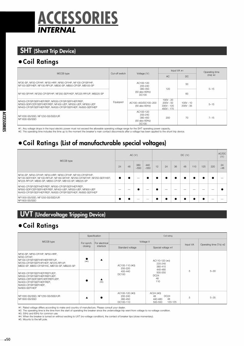
50
epytBCCM
CA )V( CD )V(CD/CA
)V(
42 84083055~
044055~
21 42 63 84 011 521 0224284~
,PH/PS/PC-001FN,PH/PC-06FN,PRH-05FN,PH/PC-05FN,PS-03FN,PEH/PES-052FN,PH/PS/PC-052FN,PH/PS-061FN,PU/PR-001FN,PEH/PES-001FN
PS-522BM,PS-001BM,PS/PC-05BM,PS-03BM,PU/PR-522FN● ● — ● ● ● ● ● ● ● ● —
● ● — ● ● ● ● ● ● —
— — ● —
—
● — — — — — —
—
●NF400-CP/SP/SEP/HEP/REP, NF630-CP/SP/SEP/HEP/REP,NF800-SDP/CEP/SEP/HEP/REP, NF400-UEP, NF630-UEP, NF800-UEPNV400-CP/SP/SEP/HEP/REP, NV630-CP/SP/SEP/HEP, NV800-SEP/HEP
NF1000-SS/SSD, NF1250-SS/SSD/URNF1600-SS/SSD
SHT (Shunt Trip Device)
epytBCCM hctiwsffo-tuC egatloV )V(AVtupnI ✳ 1 emitgnitarepO
)sm( ✳ 2CA CD
,PH/PS/PC-001FN,PH/PC-06FN,PRH-05FN,PH/PC-05FN,PS-03FNPS-001BM,PS/PC-05BM,PS-03BM,PU/PR-001FN,PEH/PES-001FN
deppiuqE
021-001CACA 042-002CA 054-083
)zH06osla05(001CD
021
05
51~5
PS-522BM,PU/PR-522FN,PEH/PES-052FN,PH/PS/PC-052FN,PH/PS-061FN 06
021-001CACA 042-002CA 054-083
)zH06osla05(001CD
002 07 51~7
002~001CD/054~001CA)zH06osla05(
02:V00105:V002021:V033071:V054
01:V00153:V002
51~5
✳ .yticapacrewopgnitarepoTHSehtrofegnaregatlovgnitarepoelbawollaehtdeecxetontsumrewopcirtceletupniehtnispordegatlovynA.1✳ .ecivedpirttnuhsehtotdeilppaneebsahegatlovaretfastcennocsidtcatnocniams’rekaerbehttnemomehtotpuemitehtsedulcniemitgnitarepoehT.2
NF400-CP/SP/SEP/HEP/REP, NF630-CP/SP/SEP/HEP/REP, NF800-SDP/CEP/SEP/HEP/REP, NF400-UEP, NF630-UEP, NF800-UEPNF400-CP/SP/SEP/HEP/REP, NV630-CP/SP/SEP/HEP, NV800-SEP/HEP
NF1000-SS/SSD, NF1250-SS/SSD/URNF1600-SS/SSD
•Coil Ratings
•Coil Ratings (List of manufacturable special voltages)
UVT (Undervoltage Tripping Device)
•Coil Ratings
epytBCCM
noitacificepS gnitarlioC
.hcnysroFgnisolc
lacirtceleroFkcolretni
VegatloVAVtupnI )s/T(emitgnitarepO ✳ 2
egatlovdradnatS egatlovlaicepS ✳ 1
● ▲(✳ )4 (021-011CA ✳ 3)
042-022514-083084-044055-005
42CD84
011
5
5
03~5
53~5
●
▲
▲
●
(✳ )5
✳ .relaedruoytlusnocesaelP.erutcafunamfoyrtnuocdnaekamotgnidroccasreffidegatlovdetaR.1✳ .noitidnocegatlov-onotegatlovmorftnewpirtegatlovrednuehtecnisrekaerbehtgnitarepofotratsehtmorfemitehtsiemitgnitarepoehT.2✳ .3✳ When the breaker is turned on without exciting to UVT (no-voltage condition), the contact of breaker tips (close momentary)..4✳ .eloptfelehtotstnuoM.5
50Hz and 60Hz for common use.
AC100-110 (✳ 3)200-220400-440
DC100
AC100-120 (✳ 3)200-240380-450
DC100-110
AC24 (✳ 3)48440-480500-550
DC2448120-125
NF30-SP, NF50-CP/HP, NF50-HRP,NF60-CP/HP,NF100-CP/SP/SEP/HP/HEP/RP/UP,NF250-CP/SP/SEP/HP/HEP, NF225-RP/UP,MB30-SP, MB50-CP/SP/HC, MB100-SP, MB225-SP
NF400-CP/SP/SEP/HEP/REP/UEP,NF630-CP/SP/SEP/HEP/REP/UEP,NF800-CEP/SDP/SEP/HEP/REP/UEP,NV400-CP/SP/SEP/HEP/REP,NV630-CP/SP/SEP/HEP,NV800-SEP/HEP
NF1000-SS/SSD, NF1250-SS/SSD/URNF1600-SS/SSD
ACCESSORIESINTERNAL
ACCESSORIES

51
Vertical Lead-wire Terminal block (SLT)
• Makes possible contact installation between terminalblock and breaker.
• No need for correspondent terminal.• Staggered arrangement of terminal screws makes
wiring easier.• It’s also easier to perform a check for tightness of
the terminal screws.• Terminal cover for the terminal block is standard
(included).• Terminal covers come in front, rear, and plug-in
connection types.
Terminal cover
M 3.5Self-lifting terminalscrew
B86
.5
38.5
86.5
2510
.510
.526
.514
.5
A C
13.5
12.5
7
18
8
ACCESSORIES
ACCESSORIESINTERNAL
Terminal cover
M 3.5Self-lifting terminalscrew
B86
.5
38.5
86.5
2510
.510
.526
.514
.5
A E
13.5
52D
92C
12.5
7
18
8
Terminal cover
A
B
8
75
60 47 33
88
M 3.5Self-lifting terminalscrew
115
4111
911
11
17
7
25
✳ Tightening torque for terminal screws: M3.5 0.9~1.2 N•m
A
20
117
20
117
B
60
100
69
116
MCCB ELCB
NF400-CP/SP/SEP/HEP/REP
NF400-UEP (3P)
NF630-CP/SP/SEP/HEP/REP
NF800-SDP/SEP/HEP/REP
NF400-UEP (4P), NF630-UEP
NF800-UEP
NV400-CP/SP/SEP/HEP/REP
NV630-CP/SP/SEP/HEP
NV800-SEP/HEP
Key to dimensions
•MCCBs •ELCBs
epytBCCM A B C
44.5
54
4.54
,PH/PC-06FN,PH/PC-05FN,PS-03FN
SC-03FN
PS/PC-05BM,PS-03BM7 5.71
,PEH/PES-001FN,PH/PS/PC-001FN,PRH-05FNPS-001BM
7
03
PU/PR-001FN 19
,PEH/PES-052FN,PH/PS/PC-052FN,PH/PS-061FNPS-522BM
73
PU/PR-522FN 211
PER/PEH/PES/PS/PC-004FN 14 5.97
)P3(PEU-004FN 831 5.911
,PER/PEH/PES/PS/PC-036FNPER/PEH/PES/PEC/PDS-008FN
14 5.88
PEU-008N,PEU-036FN,)P4(PEU-004FN 831 5.531
✳ N•m2.1~9.05.3M:swercslanimretrofeuqrotgninethgiT
Key to dimensions
D
—
21.5
30
37
79.5
88.5
E
44.5
54
PS/PC-05NM,PH/PC-06VN,PH/PC-05VN,PS-03VN
NV30-CS, MN30-CS
PS-001NM,PEH/PES-001VN,PH/PS/PC-001VN
PS-522NM,PEH/PES-522VN,PH/PS/PC-522VN
PER/PEH/PES/PS/PC-004VN
PEH/PES-008VN,PEH/PES/PS/PC-036VN
✳
C
—
3.5
2.5
2.5
26.5
26.5
B
4.5
17.5
30
37
79.5
88.5
A
4
7
41
41
ELCB type
Tightening torque for terminal screws: M3.5 0.9~1.2 N•m
Key to dimensions
•14 Terminal (SLT)

52
PAL OUT LED
Reset switch
Indicator lamp (Example)
(AC 100V or AC200V)Control power pre-alarm output
PALa
P2
P1
(PALc)
In the case of flush plate type. this is mounted on back side of the circuit breaker.
RISET
Pre-Alarm Module (PAL-M)
This module functions to give alarm output whenload current exceeds a preset current level andserves for securing continuous power supply andalso for preventive maintenance. The electronicbreakers with mount digital ETR of 100 to 800AF
epyTDELmrala-erP)teserotuA(
-tuptuo)RSS(yaleretatsdiloS)teserotuA(tuptuoseitcatnoC
)a1(tuptuotcatnoC-eludommrala-erP
yticapacgnihctiwS )gnidloh-fleS( yticapacgnihctiwS metsysteseR
PEH-001FNPES-001FN
tnempiuqedradnatS
Option
Option
CAV002-001CDV42Am02
noitpOroCAV001A2CAV002
rohctiwsteserehtsserP.rewoplortnocffonrut
PEH-052FNPES-052FN
PEH-001VNPES-001VN—
PEH-522VNPES-522VNPER-004FNPEH-004FNPES-004FNPEH-036FNPES-036FNPEU-004FNPEC-008FNPEU-036FNPER-036FNPER-008FNPEH-008FNPES-008FN
PEU-008FNCAV002-001CDV42
Am02PER-004VNPEH-004VNPES-004VNPES-008VNPEH-036VNPES-036VN
PEH-008VN
•Pre-alarm characteristics
are provided with this module as an option.(Some modules are with this module as standardequipment.) 1000 to 2000AF are prepared forexclusive use.
➀ Pre-alarm LED The LED starts blinking on the circuit breaker when load current exceeds the preset current, then changes to continuous glowing when pre-alarm output is given.
② Solid-state relay output Open the upper cover of the circuit breaker, connect the connector of the lead wire packed together and use it as the lead wire outlet. In this case, only the lead wire outlet of the internal accessories can be attached to the right pole. (For flush plate type, the outlet is manufactured in advanced as a PAL mount.)
➂ Pre-alarm module SLT is attached as standard and is used as the control power source of 100VAC or 200VAC. In this case, no other internal accessories can be attached to the right pole. (Auto resetting is also applicable.)
Pre-alarm pick-up current
LTD operating time TL12-60-100-150s ± 20%(at 200%)
60 70 100 125 200 300 400 500 600 700 1000 15000.1s
0.2s
0.5s
1s
2s
5s
10s
20s30s
1min
2min
4min6min
10min14min20min30min
1h
2h
5h
Pre-alarmpickup current IpIr x(0.7-0.75 -0.8-0.85-0.9 ± 10% -0.95-1.0)
Pre-alarmoperatiing time Tp
± 20%
(at 200%)
Tp=2TL
Current
Op
erat
ing
time
Percentage (%) to rated current or preset current rating(NF/NV100,250AF)
Percentage (%) to rated current or preset current rating(NF/NV400,630,800AF)
Pre-alarm pick-up current
LTD operating time TL12-60-100-150s ± 20%(at 200%)
60 70 100 125 200 300 400 500 600 700 1000 15000.1s
0.2s
0.5s
1s
2s
5s
10s
20s30s
1min
2min
4min6min
10min14min20min30min
1h
2h
5h
10h
Pre-alarmpickup current IpIr x(0.7-0.75 -0.8-0.85-0.9 ± 10% -0.95-1.0)
Pre-alarmoperatiing time Tp
± 20%
(at 200%)
Tp=2TL
Current
Op
erat
ing
time
ACCESSORIESINTERNAL
ACCESSORIES
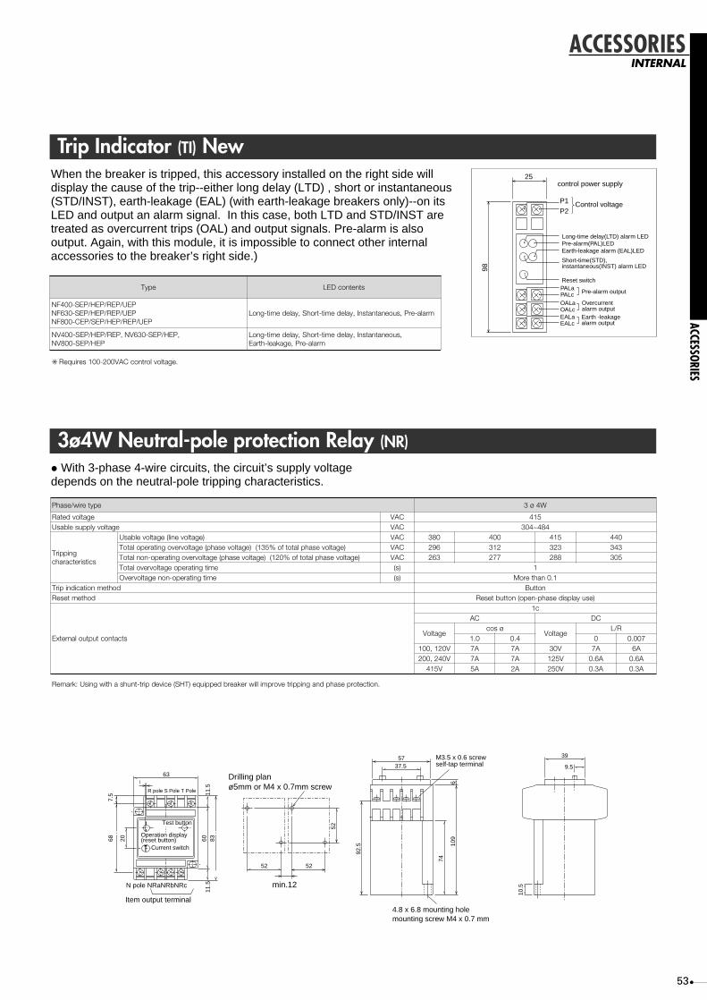
53
Trip Indicator (TI) NewWhen the breaker is tripped, this accessory installed on the right side willdisplay the cause of the trip--either long delay (LTD) , short or instantaneous(STD/INST), earth-leakage (EAL) (with earth-leakage breakers only)--on itsLED and output an alarm signal. In this case, both LTD and STD/INST aretreated as overcurrent trips (OAL) and output signals. Pre-alarm is alsooutput. Again, with this module, it is impossible to connect other internalaccessories to the breaker’s right side.)
control power supply
Long-time delay(LTD) alarm LEDPre-alarm(PAL)LEDEarth-leakage alarm (EAL)LED
Reset switch
Pre-alarm output
Overcurrentalarm outputEarth -leakagealarm output
PALaPALcOALaOALcEALaEALc
Short-time(STD),instantaneous(INST) alarm LED
Control voltageP1
25
98
P2
epyT stnetnocDEL
PEU/PER/PEH/PES-004FNPEU/PER/PEH/PES-036FN
PEU/PER/PEH/PES/PEC-008FNmrala-erP,suoenatnatsnI,yaledemit-trohS,yaledemit-gnoL
,suoenatnatsnI,yaledemit-trohS,yaledemit-gnoLmrala-erP,egakael-htraE
✳ .egatlovlortnocCAV002-001seriuqeR
NV400-SEP/HEP/REP, NV630-SEP/HEP,NV800-SEP/HEP
epyteriw/esahP W4ø3
egatlovdetaR CAV 514egatlovylppuselbasU CAV 484~403
gnippirTscitsiretcarahc
)egatlovenil(egatlovelbasU CAV 083 004 514 044)egatlovesahplatotfo%531()egatlovesahp(egatlovrevognitarepolatoT CAV 692 213 323 343
)egatlovesahplatotfo%021()egatlovesahp(egatlovrevognitarepo-nonlatoT CAV 362 772 882 503emitgnitarepoegatlovrevolatoT )s( 1emitgnitarepo-nonegatlovrevO )s( 1.0nahteroM
dohtemnoitacidnipirT nottuBdohtemteseR )esuyalpsidesahp-nepo(nottubteseR
stcatnoctuptuolanretxE
c1CA CD
egatloVøsoc
egatloVR/L
0.1 4.0 0 700.0V021,001 A7 A7 V03 A7 A6V042,002 A7 A7 V521 A6.0 A6.0
V514 A5 A2 V052 A3.0 A3.0
.noitcetorpesahpdnagnippirtevorpmilliwrekaerbdeppiuqe)THS(ecivedpirt-tnuhsahtiwgnisU:krameR
3ø4W Neutral-pole protection Relay (NR)
• With 3-phase 4-wire circuits, the circuit’s supply voltagedepends on the neutral-pole tripping characteristics.
ACCESSORIES
ACCESSORIESINTERNAL
52 52
52
min.12
Drilling planø5mm or M4 x 0.7mm screwR pole S Pole T Pole
687.
5
20 6011
.511
.583
63
Test button
Operation display(reset button)
Current switch
N pole NRaNRbNRc
Item output terminal4.8 x 6.8 mounting holemounting screw M4 x 0.7 mm
M3.5 x 0.6 screwself-tap terminal
5737.5
92.5
74
610
9
10.5
39
9.5

54
Measuring Display Unit (MDU)
• Energy management becomes possible bymeasurement and display of load current, linevoltage, electric power, electric energy, harmoniccurrent (3rd, 5th, 7th and total) and power factor ofMDU.
• MDU with pulse output option can output pulse whenelectric energy accumulated setting unit. MDU withCC-Link option can transfer measured data to opennetwork CC-Link.
• When a circuit breaker outputs a alarm, LED onMDU turns on.
PAL : pre-alarmOVER : over current
• When the circuit breaker is tripped, fault cause andfault current stored in EEPROM. It makes causeinvestigation and restoration of power line possible.
Fault cause : over current (L) and short-circuit (SI)Fault current : up to 16 times the max. rated
current can be displayed.• The max. demand value of load current, line voltage
total harmonic current, electric power and electricenergy (hourly value), are stored in EEPROM. AndMDU with CC-Link option can store the outbreaktime of these. It makes easy finding of peak time ofpower consumption possible.
ACCESSORIESINTERNAL
ACCESSORIES Load current : Present value, demand value, maximum demand value
Line voltage : Present value, demand value, maximum demand value
Harmonic current (3rd, 5th, 7th and total harmonics) :
Present value, demand value, maximum demand value
Electric power : Present value, demand value, maximum demand value
Electric energy :
Electric energy, electric energy (hourly value), maximum electric energy (hourly value)
Power factor : Present value
Rated (maximum) measuring current (note2.)
Accuracy of measurring current
Rated (maximum) measuring voltage (note2.)
Accuracy of measurring voltage
Measurment range of power factor
Fault current/cause
PAL, OVER
Pre-alarm (PAL) (Power supply AC/DC100-240V required)
Trip indicator (TI) (Power supply AC/DC100-240V required)
Phasing line
Electric energy accumulated pulse output (option) (note3.)
CC-Link transmission (option) (note3.)
Control power (Allowable voltage range 85~110%)
Items
Measured and
displayed
value
Alarm LED
indication
Alarm contact
output (option)
(note1.)
NF400-SEPM/HEPM
,
,
,
,
,
,
400A (800A)
±10A
NF630-SEPM/HEPM
,
,
,
,
,
,
630A (1260A)
±15.7A
AC440V (690V)
±11V
Lead 0~1~0 Lag
,
,
,PAL
,PAL, OAL
3φ3W, 1φ3W (3 poles breaker), 3φ4W (4 poles breaker)
,
,
AC/DC100-240V 12VA(note4.)
NF800-SEPM/HEPM
,
,
,
,
,
,
800A (1600A)
±20A
Type
Note1. The module (terminal) is attached to the right side of the breaker.Pre-alarm (PAL) output function can set “Self-holding” or “Auto reset”.For function of alarm contact output (PAL, OAL), MDU and the circuit breaker must be connected with the mutuality and the control power must be supplied to MDU and alarm contact output module.
Note2. If input is over range, in this case, MDU display maximum measuring value.Note3. Pulse output option and CC-Link option cannot be attached at the same time.Note4. When control power supplied to MDU, then rushed current transitionally, max. 40Apeak, 1ms (at 240VAC).

55
Breaker mountingNF400~800-SEPM/HEPM
Hold dimensions
M6 screwor
Breaker
I
H
102
25.565
MDU
Conductorsthickness
tE
107
F
G
G
97
1035
B
155
131
Trip button
14M12 bolt
Terminalcover
140 (400AF)
A
51
2056
.5
98B
D
25
C
FG
12.5
A Frame400630800
A70105105
B393232
C798787
D257275275
E8812
F8810
G444446
H447070
I194243243
A Frame400630800
J504646
K68103103
L598686
M598686
N715656
O718686
P237246246
Q367376376
R198214214
Please contact our company about outline of 4P and outline of contact alarm output.Hold dimensions is 1.0mm clearance on the side of the circuit breaker cut out.Please contact our company about outline CC-Link and Terminal arrange of CC-Link Panel mounting.
note 1 :
K
R2
38
2512
8
24
46
ML
R6
J
ON
Front panel cut out
Breaker mountS
EP
M(P
), H
EP
M(Q
)RFront panel cut out
136
R3
MDU is connected with circuit breaker via flat cable.Space greater than the values shown in the figure below must be secured.
140
7672
30
Upper side
Flat cableconnector
82
PE
Panel holder plate
48
12
137
140 Operation/display side
Panel
MDU terminal plate
Mounting MDU panel
note 2 : Please contact our company about outline of CC-Link and Terminal arrange of CC-Link Panel mounting.
DGSLDFGFG
FG DB DA– – 114113
––––breaker mounting
CC-Link
no transmissionPULSE
1 2 3 54
CC-Link
––
–––
113
–
114no transmissionPULSE
Panel mounting
note 2
1 2 3 4
MDU Terminal arrange
Terminal cover
Panel mounting
FG L1L21 2 3 4
Breaker mounting
L2 1 2 3 54L1
MDU control power supply
210 (630, 800AF)
7
ACCESSORIES
ACCESSORIESINTERNAL
Mode selectionswitch
Phase selectionswitch
Measured valueselection switch
Functionselection switch
Alarm resetswitch
ENTER switch
UP/DOWN switch
Numerical display LED (6digit)
Mode selection LED
Phase selectionLED
Measured value selection LED
Function selection LED
Alarm displayLED
Unit displayLED
UP/DOWN active LEDM e a s u r i n gD i s p l a yU n i t
ENTER
MODE PHASE VALUE FUNCTION ALARMA
V
W
Wh
I1 V1-2
I2 V2-3
I3 V3-1
PRESENT
MAX.
DEMAND
DEMAND TIME
CLEAR
kWh/imp
ALARM HOLD
PAL
OVER
HARMONICS
TRIP
PFALARM RESET
m
k
%
A
V
W
Wh
Measuring Display Unit

56
Electrically Operated MCCBs and ELCBs
■ General precautions for motor-operatedelectrical MCCBs
• Motor-operated types have intermittent ratings, andtherefore they should not be operated more than 10times consecutively (one on/off counts as anoperation).
• The operating voltage should be between 85~110%of the rated control voltage.
• When the breaker is tripped by trip button orbreakdown (i.e., overload or short circuit), thebreaker will not show that it has been tripped (exceptfor motor-operated type 1 breakers).
• The dielectric strength of the electrical operating
circuits is 1500V. When performing a dielectricstrength test simultaneously with another device at avoltage over 1500V, the operating circuit terminalshould be disconnected.
■ Automatic Reset• If the breaker is an auto reset type, it contains a built-
in alarm switch and the off-control circuit closeswhen the breaker is tripped. Since the breakerautomatically resets itself after tripping, the power iseasily restored by switching on the breaker again.With a UVT mounted, however, auto reset may notbe possible. In this case, please consult your dealer.
a) Motor-operated type (1)(MD)
b) Motor-operated type (2)(MD)
c) Spring-charged type (MDS)
BCCMepyt
seiresC-FN NF400-CP NF630-CP NF800-CEP NF400-CP NF630-CP NF800-CEP
seiresS-FN
PS-004FNPER/PEH/PES-004FN
PS-036FNPER/PEH/PES-036FNPER/PEH/PES-008FN
NF1000-SSNF1000-SSDNF1250-SSNF1250-SSDNF1600-SSNF1600-SSD
NF1250-UR
PS-004FNPER/PEH/PES-004FN
PS-036FNPER/PEH/PES-036FNPER/PEH/PES-008FN
seiresBM,U-FN NF400-UEP NF630-UEP NF800-UEP NF400-UEP NF630-UEP NF800-UEP
BCLEepyt
seiresC-VN PC-036VNPC-004VN PC-036VNPC-004VN
seiresS-VN
seiresNM — —
—
—
—
—
metsysnoitarepolacirtcelE )2(epytdetarepo-rotoM Motor-operated type (2)
NF1000-SSNF1000-SSDNF1250-SSNF1250-SSDNF1600-SSNF1600-SSD
NF1250-UR
—
—
—
—
Spring-charged typeepytdegrahc-gnirpS
)V(egatlovgnitarepodetaRegnaregatlovelbawollA(
)%011~58 ✳ 1
CAV022/002,CAV011/001,CDV011/001)CAV042,CDV521(
FFO NO FFO NO
gnitarepOtnerruc)smr,A( ✳ 2
CD V011/001 )0.3(0.1 8
CAV011/001 )0.3(0.1 8
V022/002
)0.8(0.3
)0.8(0.4
)5.4(0.2
)0.8(0.4
10.0)(0.5
)0.7(5.3 )5.1(5.0 7
emitgnitarepO)s(
nO)gnidloh-fles(3.0nahtsseL )gnidloh-fles(3.0nahtsseL
50.0
ffO )gnidloh-fles(3nahtsseL
remrofsnartderiuqeR)AV(yticapac
PC-001FNPC-052FN
PRH-05FNPEH/PES-001FNPH/PS-001FN
PH/PS-052FNPH/PS-061FNPEH/PES-052FN
PU-001FNPR-001FNPU-522FNPR-522FNPS-522BMPS-001BM
PC-001VNPC-522VN
PEH/PES-001VNPH/PS-001VNPEH/PES-522VNPH/PS-522VN
PS-001NMPS-522NM
)1(epytdetarepo-rotoM
CDV022-001/CAV042-001CDV42
02.0
05.0
53.0
)gnidloh-fles(5.0nahtsseL
001 007004 007 007
)0.3(0.1 9
)0.3(0.1 8
)5.1(5.0 7
70.0
)gnidloh-fles(3nahtsseL
)V(egatlovecnarudnE 0051
✳ .relaedruoytlusnoc,sliatedroF.rotsiserlanretxenaeriuqerthgimdnasnoitpolaicepserasegatlov)(.1✳ .stnerrucgnitratsswohs)(.2
NV400-SPNV400-SEP/HEP/REP
NV630-SEP/HEPNV800-SEP/HEP
NV400-SPNV400-SEP/HEP/REP
NV630-SEP/HEPNV800-SEP/HEP
•Specifications
ACCESSORIESEXTERNAL
ACCESSORIES

57
noitcennoC tnorF raeR hsulF ni-gulP ✳ 1
FA
052~05 ● ● ● ●
008~004 ● ● ● ●
1000~1250 ● ● ● ●
1600 ● ● ● —
.epytelop-3etairporppaehtmorfeloplartnecehtgnivomerybdetcurtsnocerasrekaerbelop-2llA:skrameR✳ .1 For NV types, only 3-pole of 100 and 225AF available.
•Terminal connections
P2 P1
K1 K3K3
K3
K1 K2
K2 K5
K5
K5
K4
K4
K4
CV
LS3 LS2
LS1
S1 S2 S4
ON OFF
M
ON controlcircuit
OFF controlcircuit
VC
ylppusrewopgnihctiwS)ledomegatlovitlum(
kcatsedoiD)ledomcdV42(
1SLhctiwstimiL
)noitcetednoitisopmacrof(
2SLeldnahrekaerbrof(hctiwstimiL
)noitcetednoitisop
3SLhctiwstimiL
)rotcelesOTUA/LAUNAM(
M rotoM
1K )noitarepoNOrof(yaleR
2K )noitarepoFFOrof(yaleR
3K )rotomrof(yaleR
4K )rotomrof(yaleR
5K )rotomrof(yaleR
ACCESSORIES
ACCESSORIESEXTERNAL
•Structure and Operation■ Motor-operated type (1) •Electrical operationMotor rotation is changed by DC motor, gear and camto linear motion to switch the breaker ON and OFF(reset).• Manual operationSet the slide switch to Manual. Insert the handle androtate it clockwise for ON or anticlockwise for OFF(reset). After manual operation is complete, turn theslide switch back to Auto.• Cautions during electrical operation1. When performing ON and OFF (reset) switching,the current flow is very low (approx. 15mA, DC24V).Therefore the operating switch should be suitable forlow current.2. If the breaker has a UVT attached, do not givecontinuous OFF signals.3. For automatic resetting system, use the alarmswitch (for microload) of the circuit breaker and wire the operation switch circuitry(between terminals S1, S2 and S4) as shown in Fig. 1.Notice that in a circuit without interlocking as shown inFig. 2, application is made immediately after resetting if the circuit-breaker tripswhen the ON signal is applied continuously. Take care not to allow the continuousapplication of the ON signal.
Moter-operated device
S1 S2 S4
OFF
ON
AL"a"
Moter-operated device
S1 S2 S4
OFF
ON
AL"a"
4. Switching the internal power supply could interferewith nearby communications equipment such as AMradio. If this is cause for concern, it’s recommendedthat a noise filter be installed between terminals P1and P2 and the power supply.
Fig.1 Fig.2

58
Electrically Operated MCCBs and ELCBs■ Motor-operated type (2) • Electrical operation
Forward and reverse motor rotation is changed byball screw to switch the breaker ON and OFF(reset).
• Manual operationThe manual operation handle can be used to switchthe breaker ON and OFF directly.
• Cautions during electrical operation1. In case the UVT operates and a circuit breaker tripsif the breaker has a UVT, the re-closing proceduremay differ according to the state of the breaker beforetripping.When the circuit breaker trips while turned ON.....Reset (OFF) -> Turn ONWhen the circuit breaker trips while turned OFF.....Turn ON (idle tripping) -> Reset (OFF) -> Turn ON (If it fails to turn ON (idle tripping), please operateReset (OFF) and turn ON.)2. Do not send ON and OFF signals consecutively. Aninterval of at least 0.5s is required between each ONand OFF.3. For models with auto reset capability, resetting afteran NFB trip should be performed after an interval of0.5s.4. The electrical operating device is equipped with apumping prevention circuit. Although it is possible toset the device to OFF while it is set to ON, it isimpossible to return it to ON immediately. To return toON, first shut off the ON switch, then set it back to ON.5. Special care is required during electrical operationbecause the manual operation handle moves at highspeed. Also be sure to turn off the circuit power supplywhen using manual operation.6. With manual operation, ensure that the handle isfully extended.
Manual operation
Internal structure
•Control circuitThe dotted line shows an additional connection for theautomatic-reset type.
M
Earth terminal
(DC-) P2
P1
S1
S4
95
ON
OFFRESET
Operationalpower supply
ALa
T1
T1
T1
T2LS
T2
Y
Y
Y
Y
Y
YX
X
X
X
X
Z ZZ
breaker is OFF state
M :MotorX :Relay for ON operationY :Relay for OFF operationZ :Relay for changing Motor polarityT1 :Timer ror antipumpingT2 :Timer for automatic resetLS :Limit SwitchALa :Alarm switch for automatic reset (a contact)
Earth terminal
(DC-) P2
P1
S1
S4
95
ON
OFFRESET
Operationalpower supply
ALa
T1
T1
T2 LS
Y
Y
X
Y
X
X
Y
Y
X
Z
Z
Z
XZ
M
X
Y
T2
(2) Control circuit 2.(NF1000-SS to NF 1600-SS)
(1) Control circuit 1.(400,630 and 800AF)
ACCESSORIESEXTERNAL
ACCESSORIES

59
•Control circuit
■ Spring-charged type• Electrical operation
When the ON switch is closed, the coil is excited torelease the latch mechanism and the force of theclosing spring turns the breaker ON instantly.When the OFF switch is closed, a relay starts themotor which turns the breaker OFF and charges thespring simultaneously.
• Manual operationPressing the ON button will release the latchmechanism and the force of the closing spring turnsthe breaker ON instantly.Pressing the leaf spring, pulling out the manualhandle and pumping it back and forth over 10 timeswill turn the breaker OFF and charge the spring atthe same time.
• Cautions during electrical operationWhenever an electrical operation device is to beinstalled in or removed from the breaker, the breakermust be tripped and the device discharged. Pushing the TRIP button on an MCCB with anelectrical-operation device installed will not trip thebreaker in the OFF state. This does not mean thebreaker is faulty.Switching OFF a breaker with an electrical-operationdevice installed will take 3s. If instant opening isrequired, install an SHT or UVT to the breaker.
• The breaker contains a built-in pumping-preventionrelay.
Internal structure
Internal connection
Earth terminal(DC-) P2
P1
X
X
M
X
Y Y
YCC
LS1
LS2
LS3
S2
S4
ON
OFFRESET
Operationalpower supply
Alarm switch for automatic resetting (contact a)
CC.....Coil for makingY.....Relay for pumping preventionX.....Relay for self-sustaining on OFF sideLS1...Limit switch interlocking with camLS2...Limit switch interlocking with camLS3...Limit switch interlocking with OFF lock plateM....Motor
Ala
The dotted line shows an additional connection for theautomatic-reset type.
ACCESSORIES
ACCESSORIESEXTERNAL

60
Mechanicalinterlock
Breaker
A
50
DP
B
E
2244
31 15.5
C
Stroke
70
Panel thickness(t1~3.2mm)
Gap between paneland breaker
Differs with mainbreaker unit drilling plan.
Mounts to 4-5.5mm-dia hole,7.5mm-dia countersunk (rear)*2
Mechanicalinterlock
Breaker
Mechanical interlock
External dimensions
epytrekaerB )mm(snoisnemiD
BCCM BCLEdradnatS
laicepSdradnatS
dradnatSt A B D E .giF
epyT.giF
epyT P2 P3 P3 epyT P4 P3,PH/PC-05FN,PS-03FN
PH/PC-06FN—
3PS50-IM
021 — — — — —(✳ )2—
51 33 36 5.74 85
1.giF
— —
,PH/PC-05FN,PS-03FN,PS-03BM,PH/PC-06FN
PS/PC-05BM
,PH/PC-05VN,PS-03VN,PH/PC-06VN
PS/PC-05NM— 021 — 031 4PS50-IM 021 51 33 36 — 85 3BFPS50-IM 3.giF
PS/PC-001FN —
3PS50-IM
021 — — — — — 51 33 36 54 85
1.giF
— —,PH/PS/PC-001FN,PRH-05FN
PS-001BM,PEH/PES-001FN,PH/PS/PC-001VN
PS-001NM,PEH/PES-001VN — 021 031 051 4PS1-IM 031(✳ )2—
51 3336
— 853BFPS1-IM 3.giF
PU/PR-001FN 5.23 — —,PH/PS/PC-052FN
PS-522BM,PEH/PES-052FN,PH/PS/PC-522VN
PS-522NM,PEH/PES-522VN 3PS50-IM 021 051 081 4PS2-IM 051 51 3336
— 853BFPS2-IM 3.giF
PU/PR-522FN 5.52 — —
PER/PEH/PES/PS/PC-004FN PER/PEH/PES/PS/PC-004VN3PS4-IM
091— 012 4PS4-IM 052
(✳ )2—
5.74 335.38
— 47
1.giF
2.giF
3BFPS4-IM
4.giF
)P3(PEU-004FN — — 091 5.36 —,PER/PEH/PES/PS/PC-036FN
PER/PEH/PES/PDS/PEC-008FN,PEH/PES/PS/PC-036VN
PEH/PES-008VN 3PS6-IM
M-10SS3 220
315
M-12UR3
M-16SS3
022042
—
—
—
—
—
—
4PS6-IM
MI-10SS4
MI-12UR4
MI-16SS4
092
0
2.3
92
023
624
5.74
5.74
5.74
65
33
74
74
4.55 93
7.53
7.53
5.38—
—
—
—
—
—
—
—
—
—
—
—
—
473BFPS6-IM
,PEU-036FN,)P4(PEU-004FNPEU-008FN
NF1000-SS/SSD, NF1250-SS/SSD
NF1250-UR
NF1600-SS/SSD
—
—
—
—
—
—
— 022
— 052
06 —
✳ yficepS.1 )P(hctipgnitnuomrekaerbeht✳ ).mm2.3~6.1=tssenkcihtlenapesu,FA004evobA.mm2.3~1=t:egnarssenkcihtlenapelbasU(.)t(ssenkcihtlenapehtyficepsotdeenoN.2✳ nihtiwnoitaivednoisnemidCehtpeek,sledomFA008/036/004htiwsesoprupnoitalosiroF.3 ± .mm1✳ .sliatederomroferiuqnE.4
Mechanical interlock walking type (MI-W) for electrical operating:skrameR )FA004evobA(.relaedruoytlusnoC.redrootedamebnac
Pitch (P) ✳ 1
C(✳ 3)
Breaker mount(✳ 4)
120
15 Stroke
61
4
3.5
G
120
FF
G
FFP
47.5 Stroke
94.5
45
P
Mechanical interlock Mechanical interlock
External dimensions
Breaker
Breaker
M4x0.7 screwsor 5mm-dia
M6 screwsor 7mm-dia
Mechanical terminal mount Mechanical terminal mount
Mechanical Interlocks (MI)
•Front, Rear, Plug-in
•Table of Altered Dimensions
With two breakers, use a panel-mounted mechanicalinterlock for one-way only input.A breaker-mounting mechanical to mount on thebreaker main unit can be made to order. Consult yourdealer for more details.
Fig.1 Fig.2 Fig.3 Fig.4
Front, Rear, Plug-in (panel mounting)
Breaker mounting (front)
✳ 1. Above 400AF, use panel thickness t=1.6~3.2mm.✳ 2. When the panel thickness is greater than t=2.3mm, use 4-5.5mm-dia 9.5mm dia countersunk (rear).
epyT F G
3BFPS50-IM 52 111
3BFPS1-IM 03 231
3BFPS2-IM 53 621
epyT F G P
3BFPS4-IM 44 491 091
3BFPS6-IM 07 342 062
ACCESSORIESEXTERNAL
ACCESSORIES
Drilling plan Drilling plan Drilling plan (breaker mount)
Mechanicalinterlock
Breaker
70(100)
A
31(4
0)
15.5
(20)
C
50(80)
P
44(5
5)
22(3
0)
B
Mechanicalinterlock
Breaker
Panel thickness(t1.6~3.2mm)Stroke
1.5
Gap between paneland breaker
External dimensions
Differs with mainbreaker unit drilling plan.
Mounts to 4-5.5mm-dia hole,7.5mm-dia countersunk (rear)*2
( ) dimension are shown for NF1600-SS·NF1600-SSD

61
•Flush
epytrekaerB )mm(snoisnemiD
BCCM BCLEdradnatS
A B C D E .giFepyT P2 P3 epyT P4
,PH/PC-05FN,PS-03FNPH/PC-06FN
—3PFPS50-IM
051 — — — 51 5.94 5.57 5.26 855.giF,PH/PC-05FN,PS-03FN
PS/PC-05BM,PS-03BM,PH/PC-06FN,PH/PC-05VN,PS-03VN
PS/PC-05NM,PH/PC-06VN— 051 4PFPS50-IM 571 51 5.94 5.57 — 85
PS/PC-001FN —
—
—
3PFPS1-IM
081 — — — 51 5.94 5.57 57
85
5.giF,PH/PS/PC-001FN,PRH-05FN
PS-001BM,PEH/PES-001FN,PEH/PES-001VN,PH/PS/PC-001VN
PS-001NM — 081 4PFPS1-IM 512 51 5.945.57
—
5.giFPU/PR-001FN 54
,PEH/PES-522VN,PH/PS/PC-522VNPS-522NM 3PFPS2-IM 081 4PFPS2-IM 512 51 5.94
5.57— 85
PU/PR-522FN 83
PER/PEH/PES/PS/PC-004FN PER/PEH/PES/PS/PC-004VN 3PFPS4-IM 422 4PFPS4-IM 072 5.74 35 69 — 47
5.giF
6.giF
)P3(PEU-004FN — 3PFPU4-IM — 642 — — 5.74 35 67 — 47,PER/PEH/PES/PS/PC-036FN
PER/PEH/PES/PDS/PEC-008FN,PEH/PES/PS/PC-036VN
PEH/PES-008VN3PFPS6-IM 003
300
426
4PFPS6-IM 073 5.74 35 69 — 47
PEU-008FN,PEU-036FN,)P4(PEU-004FN
NF1000-SS/SSD, NF1250-SS/SSD
NF1250-UR, NF1600-SS/SSD
——
—
3PFPU6-IM
MI-10SSFP3
MI-16SSFP3
MI-10SSFP4
MI-16SSFP4
— 413 4PFPU6-IM 383
073
83 65 56.5 395
5.74
5.74 48 36
35 5.27 ——
—
—
—
47
✳ yficepS.1 )P(hctipgnitnuomrekaerbeht
Pitch (P) (MIN) ✳ 1
NF250-CP/SP/HP, NF250-SEP/HEP,MB225-SP
•Table of Altered Dimensions
Fig.5 Fig.6
✳ 1. Above 400AF, use panel thickness t=1.6~3.2mm.
ACCESSORIES
ACCESSORIESEXTERNAL
Drilling plan
44 22
E
Mechanicalinterlock
Mechanicalinterlock
Breaker
Breaker
A Stroke Panel thickness(t1~3.2mm)
*1
20
B
Mounts with 2-5.5mm-diaand M5 x 0.8 screws.
28
Differs with breakermain unit drilling plan.
D
C
P
70
68
External dimensions
56
Mechanicalinterlock
Breakers
Mechanicalinterlock
Breakers
22(3
0)
44(5
5)28
(40) 14
(20)
C
70(100)
24
P
A
B
Panel thickness(t1.6~3.2mm)
*1
Stroke
External dimensions
Mounts with 2-5.5mm-diaand M5 x 0.8 screws.
Differs with main breakerunit drilling plan.
( ) dimension are shown for NF1250-UR·NF1600-SS·NF1600-SSD
Drilling plan

62
tcudorP )CL(revockcoL )LH(kcoleldnaH )S-LH(kcoleldnaH redlohdraC
epytrekaerB
PH/PC-06FN,PH/PC-05FN,PS-03FN P2PS50-CL P (✳ 1)S50-LH
P (✳ 1)2PS50-SLH
5.oNP-HC
PH/PC-05VN,PS-03VN,PH/PC-06FN,PH/PC-05FN,PS-03FNPS/PC-05NM,PS/PC-05BM,PS-03BM,PH/PC-06VN
P3P4
P (✳ 1)S50-SLH
PS/PC-001FN P2
PS1-CL P (✳ 1)S1-LH
P (✳ 1)2PS1-SLH
PS-001BM,PEH/PES-001FN,PS/PC-001FNPS-001NM,PEH/PES-001VN,PH/PS/PC-001VN
P3P4
P (✳ 1)S1-SLHPU/PR/PH-001FN,PRH-05FN
P2P3P4
PH/PS-061FN,PS-522BM,PEH/PES-522VN,PH/PS/PC-522VN,PEH/PES-052FN,PH/PS/PC-052FN
PU/PR-522FN,PS-522NM
P2P3P4
P (✳ 1)S2-SLH
tcudorP )TH(eldnaH )LH(kcoleldnaH )S-LH(kcoleldnaH redlohdraC
epytrekaerB
PC-004VN,PC-004FN TH - PC4 LH - P (✳ 1·2)C4P (✳ 1)S4-SLH
3.oNP-HC
PEU/PER/PEH/PES/PS-004FNPER/PEH/PES/PS-004VN
TH
HT-10SS
- PS4 LH
HL (✳ 1)
- P (✳ 1·2)S4
)P3(PEU-004FN P (✳ 1)U4-SLH
)P4(PEU-004FNPEU/PER/PEH/PES/PS/PC-036FN
PEH/PES/PS/PC-036VNPEU/PER/PEH/PES/PDS/PEC-008FN
PEH/PES-008VN
NF1000-SS/SSDNF1250-SS/SSDNF1250-URNF1600-SS/SSD
P (✳ 1)S6-SLH
:skrameR.remotsucehtybdedivorpebtsumS-LHdnaLHrofskcoldaP.1 ✳ 1. Must be ordered with breaker.
✳ 2. The HL without padlock can be used as a lock cover (LC).
—
•Handle Lock Devices, Extension Handles and Card Holders
• IEC 35mm Rail Mounting Adapters
epytrekaerBforebmuN
seloprebmunstraP
PH/PC-06FN,PH/PC-05FN,PS-03FNP2 2PS50-NID
P33PS50-NID
PS/PC-05NM,PS/PC-05BM,PS-03BM,PH/PC-06VN,PH/PC-05VN,PS-03VN P3
PS/PC-001FNP2 2PS1-NID
P3
3PS1-NIDPEH/PES-001VN,PH/PS/PC-001VN,PEH/PES-001FN,PH-001FN,PRH-05FNPS-001NM,PS-001BM
P2P3
M4 x 0.7screw
357
13
IEC 35 mm railmounting adapter
6
ACCESSORIESEXTERNAL
ACCESSORIES

63
F-Type Operating Handle
•Appearance (color: N1.5)
• Includes as standard a safety device which preventsbreaker closing as long as the cover is open. (Specifyif this safety feature is not required.)• Indicates the tripping of the breaker even in ON-lockposition--but only in cases when a single padlock(35mm) is used.• Degrees of protection (in accordance with IEC60529):IP3X (IP5X with provision of dustproof packing).
epyT epytrekaerB selopforebmuN
giF )mm(snoisnemiDMounting
swercslanretxEsnoisnemid
gnillirDnalp
✳ 5A C D E F G
P2PS50F PH/PC-06FN,PH/PC-05FN,PS-03FN P2
a c
e
501
—
111
7.0x4Mwercs5øro
—
—
rekaerBgnitnuom
swercs)scp2(
)Y(
)X(
gnitarepOeldnah
gnitnuomswercs)scp2(
PS50FPH/PC-05VN,PS-03VN,PH/PC-06FN,PH/PC-05FN,PS-03FN
PS/PC-05NM,PS/PC-05BM,PS-03BM,PH/PC-06VNP4,P3 f 52
P2PS1F PS/PC-001FN P2 e —
231PS1F
PEH/PES-001VN,PH/PS/PC-001VN,PEH/PES-001FN,PS/PC-001FNPS-001NM,PS-001BM
P4,P3
f
03
PH-001FN,PRH-05FN P4,P3,P2
PU1F PU/PR-001FN P4,P3,P2 501 03 391 5.03
PS2FPH/PS-061FN
PH/PS/PC-522VN,PEH/PES-052FN,PH/PS/PC-052FNPS-522NM,PS-522BM,PEH/PES-522VN
P4,P3,P2 701 53 621 —
PU2F PU/PR-522FN P4,P3,P2 701 53 102 5.73
PS4F PER/PEH/PES/PS/PC-004FN P4,P3,P2
b d f
381 44 491
wercs6M7øro
M8 screwor ø10
—
)Y()X(rekaerBgnitnuom
swercs)scp4(
VNPS4F PER/PEH/PES/PS/PC-004VN P4,P3
PU4F PEU-004FN P3 082 44 432 0
130
200
2
PS6FPER/PEH/PES/PS/PC-036FN
PER/PEH/PES/PDS/PEC-008FNP4,P3,P2
381 07 342 —
—
—
VNPS6F,PEH/PES/PS/PC-036VN
PEH/PES-008VNP4,P3
PU6F
F100
F1004P
F120UR
F120UR4P
PEU-008FN,PEU-036FN,)P3(PEU-004FN
NF1000-SS/SSD, NF1250-SS/SSDNF1600-SS/SSD
NF1250-UR
P4,P3
P3,P2
4P
3P
4P
082
221
225
70
70
375
375
07 092 5.32
External dimensions
150104
45 5020
A ± 2A ± 2
150
104
G
Panel thickness1.2~3.2
Panel thickness1.2~3.2
Extension handle(option)
(a) (b)
( d )( c ) ( e ) ( f )
Breaker
D
E
Breaker
D
E
(X)
(X)
(Y)
(Y)
C
78
78
90F
4- 12
112
112
118
4- 15
F
Center of breaker Center of breaker
Drilling plan
epyT
rekaerbdnaegnihforetneC
egnihtfeL egnihthgiR
H 1X H 2X
PU2F~P2PS50F eromro0 eromro)001+H5(01nahtsseL eromro071
eromro01 eromro)021+H5(
F4SP~F120UR4P eromro0 eromro)051+H8( eromro0 eromro)07+H4(
Left hinge
F-type operating handleFront panel
Right hinge
HH
X1 X2
Breaker
The figure above shows the relationship between the hingeand breaker viewed from the load side of the breaker.
ACCESSORIES
ACCESSORIESEXTERNAL
*1. Handles with NV in the product name include a test button.*2. Dustproof packing is also available as an option.*3. Other optional handles can also be mounted.*4. F4SP~F6UP are for isolation purposes. (Speify OFF lock only.)*5. The figures show the dimensions of the front connection. Some connection and
plug-in breakers have a different reference surface for mounting purposes.

64
epyT epytrekaerBgiF )mm(snoisnemiD
lanretxEsnoisnemid
nalpgnillirD A✳ 4 B✳ 4 C✳ 4 D
PS50SPH/PC-05VN,PS-03VN,PH/PC-06FN,PH/PC-05FN,PS-03FN
PS/PC-05NM,PS/PC-05BM,PS-03BM,PH/PC-06VNa c 78 201 5.401 0
PS1SPH/PS/PC-001VN,PEH/PES-001FN,PH/PS/PC-001FN,PRH-05FN
PS-001NM,PS-001BM,PEH/PES-001VN a c 78 201 5.4010
PU/PR-001FN 5.03
PS2S
PH/PS-061FNPH/PS/PC-522VN,PEH/PES-052FN,PH/PS/PC-052FN
PS-522NM,PS-522BM,PEH/PES-522VN a c 59 011 5.2110
PU/PR-522FN 5.73
P *5C4S PC-004VN,PC-004FN b d 041 651 — 0
P *5S4S
S100
PER/PEH/PES/PS-004VN,PER/PEH/PES/PS-004FNPEH/PES/PS/PC-036VN,PER/PEH/PES/PS/PC-036FN
PEH/PES-008VN,PER/PEH/PES/PDS/PEC-008FN b d
b d
261 871 —
0
0
)P3(PEU-004FN 952 572 — 02
PEU-008FN,PEU-036FN,)P4(PEU-004FN
NF1000-SS/SSD, NF1250-SS/SSD
NF1600-SS/SSD
NF1250-UR
952
199
203
215
219
572 —
—
—
5.32
S-Type Operating Handle
•Appearance (color: N1.5)
External dimensions
4511040
Decorative plate
Front panelOperating plate Operating plate
34
max
. 115
m
ax. 9
5
114
80
OF
F
ON
(a)
TRIP
5947
Operating plate
Operatingplate
max
. 145
114
130(
S4C
P·S
4SP
)18
0(S
100)
55
110
max
. 150
OF
F
TRIPON
Front panel
Decorative plate
(b)
70
17 43.5 ± 4
47
12
9
70C
± 2
B ±
2A
± 2
D
41.5
± 4
62
4.54-
Retainer
Center of breaker's handle
Front panelDeviation: 4mm or less100 or more (210 or more if hingeis mounted on the left)
Deviation: 4 mm or less
Centre of breaker
Hinge
Reference planefor mounting the breaker
Retainer(option)
Retainer*1
*1
*2
*2
*3
*3
(c)
Front panel applicable thickness : 1.2 to 3.2
84
25 102 ± 5
45
12
B ±
2A
± 2
D
35 ±
5
62
5.54-
Retainer
Front panelDeviation: 5mm or less110 or more (250 or more if hingeis mounted on the left)
Deviation: 2 mm or less
Centre of breaker
Hinge
Reference planefor mounting the breaker
Retainer(option)
Retainer*1
Center of breaker's handle
*1
*2
*5
*3
*3
(d)
84
Front panel applicable thickness : 1.6 to 3.2
Drilling plan
• Indicates the tripping of the breaker even in ON-lockposition--but only in cases when a single padlock(35mm) is used.• Degrees of protection (in accordance with IEC60529):IP5X.
ACCESSORIESEXTERNAL
ACCESSORIES
*1. Retainers are not included. They must be provided by the customer.*2. When using optional retainer.*3. Shows the tolerance for the distance from the center of a 62mm dia. hole.*4. The figures show the front-connection dimensions. Some rear-connection and plug-in breakers have a different reference surface for mounting purposes.*5. S4CP and S4SP are for isolation purposes. (Specify OFF lock only.) The tolerance is less than 5mm. It does not conform to isolation purposes, however, if the deviation is more than 2mm.

65
SS-Type Operating Handle
•Appearance (color: N1.5)
• Contact your dealer for external dimensions anddrilling plan.
epyT epytrekaerB
PS50SS,PH/PC-05VN,PS-03VN,PH/PC-06FN,PH/PC-05FN,PS-03FN
PS/PC-05NM,PS/PC-05BM,PS-03BM,PH/PC-06VN
PS1SS,PU/PR-001FN,PEH/PES-001FN,PH/PS/PC-001FN,PRH-05FN
PS-001NM,PS-001BM,PEH/PES-001VN,PH/PS/PC-001VN
PS2SS,PH/PS-061FN
,PH/PS/PC-522VN,PU/PR-522FN,PEH/PES-052FN,PEH/PS/PC-052FNPS-522NM,PS-522BM,PEH/PES-522VN
PC4SS PC-004VN,PC-004FN
PS4SS
62SS
,PER/PEH/PES/PS-004VN,PER/PEH/PES/PS-004FN,PEH/PES/PS/PC-036VN,PER/PEH/PES/PS/PC-036FN
PEH/PES-008VN,PER/PEH/PES/PDS/PEC-008FN
NF1000-SS/SSD, NF1250-SS/SSDNF1250-URNF1600-SS/SSD
)P3(PEU-004FN
PEU-008FN,PEU-036FN,)P4(PEU-004FN
ACCESSORIES
ACCESSORIESEXTERNAL

E
D
C
A B
Front panel
Panelthickness1.2~3.2
F
G
J min
K max
H
66
epyTepytsrekaerB .giF )mm(snoisnemiD
BCCM BCLE weivtuO gnillirDnalp A B C D E F G H J K L M P
PS1V,A/TPC-001FN,PC-001FN,PRH-05FN,PH-001FN,A/TPS-001FN,PS-001FN
PEH-001FN,PES-001FN,A/TPH-001FN
,PS-001VN,PC-001VN,PES-001VN,PH-001VN
PEH-001VNa e,c
551 09 09 09 61 94 14 16 451 815 231 03 001+N5
PS2V
,PH-061FN,A/TPS-061FN,PS-061FN,A/TPC-052FN,PC-052FN,A/TPH-061FN
,PH-052FN,A/TPS-052FN,PS-052FNPEH-052FN,PES-052FN,A/TPH-052FN
,PS-522VN,PC-522VN,PH-522VN,PES-522VN
PEH-522VN561 09 501 09 61 94 34 16 451 815 621 53 001+N5
PS4V,PES-004FN,PS-004FN,PC-004VN
PEH-004FN—
b f,d
752 041 041 041 52 26 67 79 712 935 491 44 051+N8VNPS4V — PS-004VN,PC-004VN
PEH-004VN,PES-004VN
PS6V
PES-036FN,PS-036FN,PC-036FNPEH-036FN
PES-008FN,PDS-008FN,PEC-008FNPEH-008FN
572 041 012 041 52 26 67 79 712 935 342 07
Q
15
17.5
—
—051+N8NV630-CP, NV630-SPNV630-SEP, NV630-HEPNV800-SEP, NV800-HEP
V-Type Operating Handle
• Can be locked in OFF position only.• The door is locked when ON and can only be opened in OFF position.• Degrees of protection (in accordance with IEC60529): IP54.
External dimensions
Outview
L
M
Breaker
M6 screwor 7
M4x0.7 screwor 5
Center ofbreaker's handle
54 L
54
M
N X
O or more P or more
Breaker
Hinge(left side)
Hinge(right side)
X X
Front panel
Z Z
2- 9
4- 10
M4x0.7 screwor 5
54
Center ofbreaker's handle
104
104
63
Breaker
2-, 3-Pole 4-Pole
Breaker
Center of breakerCenter ofbreaker's handle
L
M M
Q(c)
(d) (f)
(e)
Drilling plan
■ Appearance
(a) (b)
ACCESSORIESEXTERNAL
ACCESSORIES

67
R-Type Operating Handle
C
D
E
F H
J
G
A
B
epyTepytrekaerB giF )mm(snoisnemiD
BCCM BCLE OutviewgnillirD
nalpA B C D E F G H J K L
PS1R,A/TPC-001FN,PC-001FN,PRH-05FN,PH-001FN,A/TPS-001FN,PS-001FN
PEH-001FN,PES-001FN,A/TPH-001FN
,PS-001VN,PC-001VN,PES-001VN,PH-001VN
PEH-001VN
a c
551 011 09 98 61 92 16 201 531 231 03
PS2R
,PH-061FN,A/TPS-061FN,PS-061FN,A/TPC-052FN,PC-052FN,A/TPH-061FN
,PH-052FN,A/TPS-052FN,PS-052FNPEH-052FN,PES-052FN,A/TPH-052FN
,PS-522VN,PC-522VN,PH-522VN,PES-522VN
PEH-522VN561 011 501 98 61 92 16 401 731 621 53
PS4R,PES-004FN,PS-004FN,PC-004FN
PEH-004FN—
b d
752 821 041 041 52 34 79 471 812 491 44
VNPS4R — ,PS-004VN,PC-004VNPEH-004VN,PES-004VN
PS6R
,PES-036FN,PS-036FN,PC-036FNPEH-036FN
,PES-008FN,PDS-008FN,PEC-008FNPEH-008FN
572 821 012 041 52 34 79 471 812 342 07
M
15
17.5
—
—NV630-CP, NV630-SP,NV630-SEP, NV630-HEP,NV800-SEP, NV800-HEP
• Can be locked in OFF position only.
External dimensions
Breaker
Center of breakerCenter ofbreaker's handle
M4x0.7 screwor 5
K
L L
M
K
L
Breaker
M4 screwor 5
K
L
Breaker
M6 screwor 7
2-, 3-Pole 4-Pole
(c) (c)(d)
Drilling plan
■ Appearance
(a) (b)
Outview
ACCESSORIES
ACCESSORIESEXTERNAL

68
epytrekaerB
revoclanimretegraL)L-CT(
revoclanimretllamS)S-CT(
lanimrettnerapsnarT)CTT(revoc
revoclanimretraeR)CTB(
revoclanimretni-gulP)CTP(
NF30-CS P2TCL-03CS2
(45✕ 30.5✕ 25)
PH/PC-06FN,PH/PC-05FN,PS-03FNPH/PC-06VN,PH/PC-05VN,PS-03VNPS/PC-05NM,PS/PC-05BM,PS-03BM
P33PS50-LCT ✳ 2
57( ✕ 5.56 ✕ )523PS50-SCT
57( ✕ 46 ✕ )53PS50-CTT ✳ 2
57( ✕ 5.56 ✕ )523PS50-CTB
57( ✕ 46 ✕ )5.63PS50-CTP
57( ✕ 46 ✕ )5.6
P44PS50-LCT
001( ✕ 5.56 ✕ )52— — — —
—
—
PS/PC-001FN P22PS1-LCT ✳ 1
06( ✕ 5.56 ✕ )042PS1-SCT
06( ✕ 5.56 ✕ )5.62PS1-CTT ✳ 1
06( ✕ 5.56 ✕ )042PS1-CTB
06( ✕ 5.56 ✕ )5.62PS1-CTP
06( ✕ 5.56 ✕ )5.6
PH/PS/PC-001VN,PEH/PES-001FN,PS/PC-001FNPS-001NM,PS-001BM,PEH/PES-001VN
P33PS1-LCT ✳ 2
09( ✕ 5.56 ✕ )043PS1-SCT
09( ✕ 5.56 ✕ )5.63PS1-CTT ✳ 2
09( ✕ 5.56 ✕ )043PS1-CTB
09( ✕ 5.56 ✕ )5.63PS1-CTP ✳ 3
09( ✕ 5.56 ✕ )5.6PU/PR-001FN,PH-001FN,PRH-05FN P3,P2
PEH/PES-001VN,PEH/PES-001FN,PU/PH/PS-001FN P44PS1-LCT
021( ✕ 5.56 ✕ )04— — — —
PH/PS-061FNPU/PR-522FN,PEH/PES-052FN,PS/PC-052FNPS-522BM,PEH/PES-522VN,PH/PS/PC-522VN
PS-522NM
P2P3
3PS2-LCT ✳ 2
✳ 2
✳ 2
501( ✕ 5.56 ✕ )043PS2-SCT
501( ✕ 5.56 ✕ )5.63PS2-CTT ✳ 2
501( ✕ 5.56 ✕ )043PS2-CTB
501( ✕ 5.56 ✕ )5.63PS2-CTP ✳ 4
501( ✕ 5.56 ✕ )5.6
PU-522FN,PEH/PES-522VN,PEH/PES-052FN,PH/PS-052FN P44PS2-LCT
041( ✕ 5.56 ✕ )05— — — —
.mmnisnoisnemidlanretxeswohS)(.1:skrameR).sgnidlomdilostonera4PS50-LCTehtnahtrehtosrevoclanimreT(.redrootedamebnacsledomelop-4rofsrevoclanimreT.2
✳ ).netsafotswercssesurevoclanimretepyt-FehT(.rebmuntcudorpehtfodneehtotFdda,eldnahgnitarepoepyt-FredrooT.1✳ .eldnahgnitarepoepyt-Fn V.R.ahtiwdradnatssadenibmocebnaC.2✳ .PR-001VNdnaPU/PR-001FNroftpecxE.3✳ .PR-522VNdnaPU/PR-522FNroftpecxE.4
NF30-CS, NV30-CS, MN30-CS P3TCL-03CS3
(67✕ 30.5✕ 25)
TCS-03CS2(45✕ 30.5✕ 5)
TCS-03CS3(67✕ 30.5✕ 5)
TTC-03CS2(45✕ 30.5✕ 25)
TTC-03CS3(67✕ 30.5✕ 25)
BTC-03CS2(45✕ 30.5✕ 6.5)
BTC-03CS3(67✕ 30.5✕ 6.5)
PH/PC-06FN,PH/PC-05FN,PS-03FN P22PS50-LCT ✳ 1
05( ✕ 46 ✕ )522PS50-SCT
05( ✕ 46 ✕ )52PS50-CTT ✳ 1
05( ✕ 46 ✕ )522PS50-CTB
05( ✕ 46 ✕ )5.62PS50-CTP
05( ✕ 46 ✕ )5.6
NF50-HPNF60-HP
Terminal Cover
ACCESSORIESEXTERNAL
ACCESSORIES
A
CB
A
CB
A
CB
A
CB
A
C
B

69
epytrekaerB
revoclanimretegraL)L-CT(
revoclanimrettnerapsnarT)CTT(
revoclanimretraeR)CTB(
revoclanimretni-gulP)CTP(
PER/PEH/PES/PS/PC-004FNPER/PEH/PES/PS/PC-004VN
P3,P23PS4-LCT ✳ 3
171( ✕ 5.99 ✕ )0111.giF
3PS4-CTT171( ✕ 5.401 ✕ )011
3PS4-CTB041( ✕ 5.99 ✕ )24
3PS4-CTP041( ✕ 5.99 ✕ )24
PEU-004FN P33PS4-LCT ✳ 1
171( ✕ 5.691/5.231 ✕ )011—
3PS4-CTB ✳ 1041( ✕ 5.691/5.231 ✕ )24
—
PEH/PES-004VN,PEH/PES/PS-004FN P44PS4-LCT ✳ 4
042( ✕ 104.5✕ 110)
2.giF
4PS4-CTT042( ✕ 5.401 ✕ )011
4PS4-CTB ✳ 2581( ✕ 5.79 ✕ )93
—
PEH/PES/PS/PC-036VN,PER/PEH/PES/PS/PC-036FNPEH/PES-008VN,PER/PEH/PES/PDS/PEC-008FN
P3,P2
3PS6-LCT ✳ 5422( ✕ 103.5✕ 155)
3PS6-CTT422( ✕ 5.301 ✕ )551
3PS6-CTB ✳ 2012( ✕ 5.79 ✕ )23
—
PEU-008FN,PEU-036FN P3
2P, 3P
3PU6-LCT ✳ 1022( ✕ 5.491/641 ✕ )551
—3PS6-CTB ✳ ,1 ✳ 2
012( ✕ 5.491/641 ✕ )23—
PES-036VN,PEH/PES/PS-036FNPEH/PES-008FN
NF1000-SS/SSDNF1250-SS/SSD
NF1000-SS/SSD
NF1250-UR
NF1250-SS/SSD
NF1250-UR
P44PS6-LCT ✳ 6
492( ✕ 103.5✕ 155)4PS6-CTT
492( ✕ 5.301 ✕ )5514PS6-CTB ✳ 2
082( ✕ 5.79 ✕ )23—
PEU-008FN,PEU-036FN,PEU-004FN P4
P4
P3
P4
4PU6-LCT ✳ 1092( ✕ 5.491/641 ✕ )551
TCL-10SS3
TCL-10SS4
TCL-12UR3
TCL-12UR4
022( ✕ 0)51✕931
092( ✕ 0)51✕931
052( ✕ 0)32✕341
023( ✕ 0)32✕341
—
—
—
—
—
—
—
—
—
4PS6-CTB ✳ ,1 ✳ 2082( ✕ 5.491/641 ✕ )23
—
—
—
—
—
A(.mmnisnoisnemidlanretxeswohS)(.1:skrameR ✕ B✕ )C✳ edisdaoL/ediseniL.1✳ .epytni-gulpnodetnuomebnacsrevocesehT.2✳ .PER/PEH-004VNdnaPER/PEH-004FNroftpecxE.3
CB
A
Fig.2
Fig.1CB
A
ACCESSORIES
ACCESSORIESEXTERNAL
C
B
A
C
B
A
C
B
A

70
CHARACTERISTICSMOLDED-CASE CIRCUIT BREAKERS
Op
erat
ing
tim
e
x100% of rated current
Min.
Max.
AC useNF50-CPNF50-HP
NF30-SPNF60-CPNF60-HP
1
0.01s
0.02s
0.05s
0.1s
0.2s
0.5s
1s
2s
5s
10s
20s30s
1min
2min
4min6min
10min14min20min30min
1h
2h
4h
1.3 2 3 4 5 6 7 10 15 20 30 40O
per
atin
g t
ime
x100% of rated current
Min.
Max.
MB30-SPMB50-CPMB50-SP
1
0.01s
0.02s
0.05s
0.1s
0.2s
0.5s
1s
2s
5s
10s
20s30s
1min
2min
4min6min
10min14min20min30min
1h
2h
4h
1.3 2 3 4 5 6 7 10 15 20 30 40
Op
erat
ing
tim
e
x100% of rated current
Min.
Max.
DC useNF50-CPNF50-HP
NF30-SPNF60-CPNF60-HP
1
0.01s
0.02s
0.05s
0.1s
0.2s
0.5s
1s
2s
5s
10s
20s30s
1min
2min
4min6min
10min14min20min30min
1h
2h
4h
1.3 2 3 4 5 6 7 10 15 20 30 40
MCCBS
•NF30-CS, NF30-SP, NF50-CP, NF60-CP, NF50-HP, NF60-HP, MB30-SP, MB50-CP, MB50-SP
•Operating Characteristics
•Temperature Characteristics
Ambient temperature (°C)Op
erat
ing
tim
e ch
ang
e ra
te (%
)
Rat
ed a
mb
ient
7080
-5 0 10 20 30 40 50
100
150
200250300
Type NF30-CS
Operating Characteristics
Max.
Min.
1 1.30.006s
0.01s
0.02s
0.04s
0.1s
0.2s
0.4s
0.6s
1s
2s
4s
6s
10s
20s
30s40s
1min
2min
4min
6min
10min
20min
40min
1h
2h
3h
0.06s
2 3 4 5 7 10 20 30 40 50 70 100
Op
erat
ing
tim
e
✕ 100% of rated current
Standard attached parts (Front connection)
Mounting screw M4x0.7x35 (2 and 3P: 2pcs, 4P: 4pcs)for NF30-CS M4x0.7x20 2pcsInsulation barrier (2P: 1pc, 3P: 2pcs, 4P: 3pcs)Only NF50-HP, NF60-HP, MB50-SP
CHARACTERISTICS

71
CHARACTERISTICSMOLDED-CASE CIRCUIT BREAKERS
•NF50-HRP, NF100-CP, NF100-SP, NF100-HP, NF100-SEP, NF100-HEP, NF100-RP, NF100-UP, MB100-SP
•Operating Characteristics
Op
erat
ing
tim
e
x100% of rated current
Time delay trip Instantaneous trip
Note: The characteristics for both AC and DC use are the same; however, the products differ from each other.
Min.
Max.
NF100-HPNF100-SPMB100-SPNF50-HRPNF100-RPNF100-UP
15A~30A15A~30A12.5A~32A15A~30A15A~30A15A~30A
1
0.01s
0.02s
0.05s
0.1s
0.2s
0.5s
1s
2s
5s
10s
20s30s
1min
2min
4min6min
10min14min20min30min
1h
2h
4h
1.3 2 3 4 5 6 7 10 15 20 30 40
0.6 0.7 1 1.3 2 3 4 5 6 7 10 30 402015
0.01s
0.02s
0.05s
0.1s
0.2s
0.5s
1s
2s
5s
10s
20s30s
1min
2min
4min6min
10min14min20min30min
1h
2h
4h
Pre-alarmpickup current IpIr x (0.70-0.75-0.8-0.85-0.9-0.95-1.0) ± 10%
Pre-alarmoperating time Tp
± 20%
(at 200%)
Tp=2TL
Current setting (✕ 100% of Ir)x 100% of rated current
Op
erat
ing
tim
e
Instantaneous tripping current (✕ 100% of In)
INST pickup current Iix 4 ~ x16±15%
(Magnification to Rated current)
Max. total breaking time
STD operating time Ts
STD pickup current IsIr x (2-2.5-3-3.5-4- 5-6-7-8-10) ± 15%
0.3 ± 0.06s0.2 ± 0.04s
0.1 ± 0.03s0.06 ± 0.02s
NF 100-SEP NF 100-HEPNote )
Current setting Ir Rated current In
12-60-80-100s±20%(at 200%)
LTD operating time TL
Note
20A50A
100A
15~20A30~50A
60~100A
Op
erat
ing
tim
e
x100% of rated current
Time delay trip Instantaneous trip
Note: The characteristics for both AC and DC use are the same; however, the products differ from each other.
Min.
Max.(60A ~ 100A)
Max.(40A, 50A)
40A~100A40A~100A50A~100A40A~100A40A,50A40A~100A40A~100A
1
0.01s
0.02s
0.05s
0.1s
0.2s
0.5s
1s
2s
5s
10s
20s30s
1min
2min
4min6min
10min14min20min30min
1h
2h
4h
1.3 2 3 4 5 6 7 10 15 20 30 40
NF100-HPNF100-SPNF100-CPMB100-SPNF50-HRPNF100-RPNF100-UP
•Temperature Characteristics
Ambient temperature (°C)
(Rated ambient 30°C)
Cur
rent
rat
ing
(%)
Rat
edam
bie
nt
-580
90
100
110
120
130
15~30A
40~100A
0 10 20 30 40
Standard attached parts (Front connection)
Mounting screw M4x0.7x35 (2 and 3P: 2pcs, 4P: 4pcs)for NF100-RP and NF100-UP M4x0.7x35 4pcsInsulation barrier (2P: 1pc, 3P: 2pcs, 4P: 3pcs)
CHARACTERISTICS
Ambient temperature (°C)
Co
ntin
uous
load
cur
rent
(%)
80
70
90
100
110
120
130
0 10 20 30 40 50 60
Rat
ed a
mb
ient

72
Time-delay trip Instantaneous trip
Op
erat
ing
tim
e
x100% of Ir
Min.
Max.
Thermal-Adjustable types
NF100-SPNF100-HPNF100-CP
1
0.01s
1min
1h
0.02s
0.05s
0.1s
0.2s
0.5s
1s
2s
5s
10s
20s30s
2min
4min6min
10min14min20min30min
2h
4h
1.3 2 3 4 5 6 7 10 15 20 30 40
Max. totalinterruptingtime
Instantaneous trip current1200A±240A
80-100AIr
80Ampererating
100Ampererating
Time-delay trip Instantaneous trip
Op
erat
ing
tim
e
x100% of Ir
Min.
Max.
Thermal-Adjustable types
NF100-SPNF100-HPNF100-CP
1
0.01s
1min
1h
0.02s
0.05s
0.1s
0.2s
0.5s
1s
2s
5s
10s
20s30s
2min
4min6min
10min14min20min30min
2h
4h
1.3 2 3 4 5 6 7 10 15 20 30 40
Max. totalinterruptingtime
Instantaneous trip current600A±120A
40-63AIr
40Ampererating
63Ampererating
Time-delay trip Instantaneous trip
Op
erat
ing
tim
e
x100% of Ir
Min.
Max.
Thermal-Adjustable types
NF100-SPNF100-HPNF100-CP
1
0.01s
1min
1h
0.02s
0.05s
0.1s
0.2s
0.5s
1s
2s
5s
10s
20s30s
2min
4min6min
10min14min20min30min
2h
4h
1.3 2 3 4 5 6 7 10 15 20 30 40
Max. totalinterruptingtime
Instantaneous trip current945A±189A
63-80AIr
63Ampererating
63Ampererating
80Ampererating
80Ampererating
MCCBS
•NF100-CP T/A, NF100-SP T/A, NF100-HP T/A
•Operating Characteristics
•Temperature Characteristics
Ambient temperature (°C)(rated ambient 40°C)
Cur
rent
rat
ing
(%)
0 10 20 30 40 50 6080
90
100
110
120
130
25-40A40-63A
15-20A20-25A
Rat
edam
bie
nt
63-80A80-100A
Standard attached parts (Front connection)
Mounting screw M4x0.7x35 (2 and 3P: 2pcs, 4P: 4pcs)Insulation barrier (2P: 1pcs, 3P: 2pcs, 4P: 3pcs)
CHARACTERISTICSMOLDED-CASE CIRCUIT BREAKERS
CHARACTERISTICS

73
•NF100-CP T/A, NF100-SP T/A, NF100-HP T/A
•Operating Characteristics
Time-delay trip Instantaneous trip
Op
erat
ing
tim
e
x100% of Ir
Min.
Max.
Thermal-Adjustable types
NF100-SPNF100-HPNF100-CP
1
0.01s
1min
1h
0.02s
0.05s
0.1s
0.2s
0.5s
1s
2s
5s
10s
20s30s
2min
4min6min
10min14min20min30min
2h
4h
1.3 2 3 4 5 6 7 10 15 20 30 40
Max. totalinterruptingtime
Instantaneous trip current375A±75A
25-40AIr
25Ampererating
40Ampererating
Time-delay trip Instantaneous trip
Op
erat
ing
tim
e
x100% of Ir
Min.
Max.
Thermal-Adjustable types
NF100-SPNF100-HPNF100-CP
1
0.01s
1min
1h
0.02s
0.05s
0.1s
0.2s
0.5s
1s
2s
5s
10s
20s30s
2min
4min6min
10min14min20min30min
2h
4h
1.3 2 3 4 5 6 7 10 15 20 30 40
Max. totalinterruptingtime
Instantaneous trip current225A±45A
15-20AIr
15Ampererating
20Ampererating
Time-delay trip Instantaneous trip
Op
erat
ing
tim
e
x100% of Ir
Min.
Max.
Thermal-Adjustable types
NF100-SPNF100-HPNF100-CP
1
0.01s
1min
1h
0.02s
0.05s
0.1s
0.2s
0.5s
1s
2s
5s
10s
20s30s
2min
4min6min
10min14min20min30min
2h
4h
1.3 2 3 4 5 6 7 10 15 20 30 40
Max. totalinterruptingtime
Instantaneous trip current300A±60A
20-25AIr
20Ampererating
25Ampererating
•Temperature Characteristics
Ambient temperature (°C)(rated ambient 40°C)
Cur
rent
rat
ing
(%)
0 10 20 30 40 50 6080
90
100
110
120
130
25-40A40-63A
15-20A20-25A
Rat
edam
bie
nt
63-80A80-100A
CHARACTERISTICS
CHARACTERISTICSMOLDED-CASE CIRCUIT BREAKERS

74
CHARACTERISTICS
CHARACTERISTICS
MOLDED-CASE CIRCUIT BREAKERS
Op
erat
ing
tim
e
x100% of rated current
Time delay trip Instantaneous trip
Note: The characteristics for both AC and DC use are the same; however, the products differ from each other.
Min.
Max.
NF160-SPNF160-HP
NF250-CPNF250-SPNF250-HPNF225-RPNF225-UPMB225-SP
1
0.01s
0.02s
0.05s
0.1s
0.2s
0.5s
1s
2s
5s
10s
20s30s
1min
2min
4min6min
10min14min20min30min
1h
2h
4h
1.3 2 3 4 5 6 7 10 15 20 30 40
Max. totalinterrupting time
125~225A
250A
MCCBS
0.6 0.7 1 1.3 2 3 4 5 6 7 10 30 402015
0.01s
0.02s
0.05s
0.1s
0.2s
0.5s
1s
2s
5s
10s
20s30s
1min
2min
4min6min
10min14min20min30min
1h
2h
4h
Pre-alarmpickup current IpIr x (0.70-0.75-0.8-0.85-0.9-0.95-1.0) ±10%
Pre-alarmoperating time Tp
±20%
(at 200%)
Tp=2TL
Current setting (✕ 100% of Ir)x 100% of rated current
Op
erat
ing
tim
e
Instantaneous tripping current (✕ 100% of In)
INST pickup current Iix 4 ~ x14 ±15%
(Magnification to Rated current)
Max. total breaking time
STD operating time Ts
STD pickup current IsIr x (2-2.5-3-3.5-4- 5-6-7-8-10) ±15%
0.3 ± 0.06s0.2 ± 0.04s
0.1 ± 0.03s0.06 ± 0.02s
NF250-SEP NF250-HEPNote )
Current setting Ir Rated current In
12-60-80-100s ±20%(at 200%)
LTD operating time TL
Note
250A125~250A(Adjustable)
•NF160-SP, NF160-HP, NF250-CP, NF250-SP, NF250-HP, NF250-SEP, NF250-HEP, NF225-RP, NF225-UP, MB225-SP
•Operating Characteristics
•Temperature Characteristics
Ambient temperature (°C)(rated ambient 30°C)
Cur
rent
rat
ing
(%)
Rat
ed a
mb
ient
080
90
100
110
120
130
10 20 30 40 50-5
Standard attached parts (Front connection)Mounting screw M4x0.7x55 (2 and 3P: 2pcs, 4P: 4pcs)Insulation barrier (2P: 2pcs, 3P: 4pcs, 4P: 6pcs)
Ambient temperature (°C)
80
70
90
100
110
120
130
0 10 20 30 40 50 60
Co
ntin
uous
load
cur
rent
(%)
Rat
ed a
mb
ient
For NF225-RP and NF225-UPMounting screw M4x0.7x55 (2 and 3P: 2pcs, 4P: 4pcs)
M4x0.7x73 (2 and 3P: 2pcs)Insulation barrier (2P: 2pcs, 3P: 4pcs, 4P: 6pcs)

75
CHARACTERISTICS
CHARACTERISTICSMOLDED-CASE CIRCUIT BREAKERS
Time-delay trip Instantaneous trip
Op
erat
ing
tim
e
x100% of Ir
Min.
Max.
Thermal-Adjustable types
NF160-SP NF160-HP
1
0.01s
1min
1h
0.02s
0.05s
0.1s
0.2s
0.5s
1s
2s
5s
10s
20s30s
2min
4min6min
10min14min20min30min
2h
4h
1.3 2 3 4 5 6 7 10 15 20 30 40
Max. totalinterrupting time
Instantaneous trip current1400A±280A
125-160AAC
125Ampere rating
160Ampere rating
Ir :
Time-delay trip Instantaneous trip
Op
erat
ing
tim
e
x100% of Ir
Min.
Max.
Thermal-Adjustable types
NF160-SP NF160-HP
1
0.01s
1min
1h
0.02s
0.05s
0.1s
0.2s
0.5s
1s
2s
5s
10s
20s30s
2min
4min6min
10min14min20min30min
2h
4h
1.3 2 3 4 5 6 7 10 15 20 30 40
Max. totalinterrupting time
Instantaneous trip current1400A±280A
100-125AAC
100Ampere rating
125Ampere rating
Ir :
•NF160-SP T/A, NF160-HP T/A
•Operating Characteristics
•Temperature Characteristics
Ambient temperature (°C)(rated ambient 40°C)
Cur
rent
rat
ing
(%)
Rat
ed a
mb
ient
1080
90
100
110
120
130
20 30 40 50 605
Standard attached parts (Front connection)
Mounting screw M4x0.7x55 (2 and 3P: 2pcs, 4P: 4pcs)Insulation barrier (2P: 2pcs, 3P: 4pcs, 4P: 6pcs)

76
CHARACTERISTICSMOLDED-CASE CIRCUIT BREAKERS
CHARACTERISTICS
MCCBS
•NF250-CP T/A, NF250-SP T/A, NF250-HP T/A
•Operating Characteristics
•Temperature Characteristics
Ambient temperature (°C)(rated ambient 40°C)
Cur
rent
rat
ing
(%)
Rat
ed a
mb
ient
1080
90
100
110
120
130
20 30 40 50 605
Time-delay trip Instantaneous trip
Op
erat
ing
tim
e
x100% of Ir
Min.
Max.
Thermal-Adjustable types
NF250-CPNF250-HP
NF250-SP
1
0.01s
1min
1h
0.02s
0.05s
0.1s
0.2s
0.5s
1s
2s
5s
10s
20s30s
2min
4min6min
10min14min20min30min
2h
4h
1.3 2 3 4 5 6 7 10 15 20 30 40
Max. totalinterrupting time
Instantaneous trip current2500A±500A
200-250AIr :AC
200Ampererating
250Ampere rating
Time-delay trip Instantaneous trip
Op
erat
ing
tim
e
x100% of Ir
Min.
Max.
Thermal-Adjustable types
NF250-CPNF250-HP
NF250-SP
1
0.01s
1min
1h
0.02s
0.05s
0.1s
0.2s
0.5s
1s
2s
5s
10s
20s30s
2min
4min6min
10min14min20min30min
2h
4h
1.3 2 3 4 5 6 7 10 15 20 30 40
Max. totalinterrupting time
Instantaneous trip current2100A±420A
150-200AAC
150Ampererating
200Ampere rating
Ir :
Standard attached parts (Front connection)
Mounting screw M4x0.7x55 (2 and 3P: 2pcs, 4P: 4pcs)Insulation barrier (2P: 2pcs, 3P: 4pcs, 4P: 6pcs)

77
CHARACTERISTICS
Ambient temperature (°C)
Rat
ed a
mb
ient
80
70
90
100
110
120
130
0 10 20 30 40 50 60
Co
ntin
uous
load
cur
rent
(%)
•NF400-CP, NF400-SP, NF400-SEP, NF400-HEP, NF400-REP
•Operating Characteristics
Time-delay trip Instantaneous trip
Op
erat
ing
tim
e
✕ 100% of rated current
Note: When ordering, please specify if for DC use.
Min.
Max.
NF400-CPNF400-SP
1
0.01s
1min
1h
0.02s
0.05s
0.1s
0.2s
0.5s
1s
2s
5s
10s
20s30s
2min
4min6min
10min14min20min30min
2h
4h
1.3 2 3 4 5 6 7 10 15 20 30 40
Max. totalinterrupting time
250 300 350 400AAC,DC
NF400-CP
NF400-SP
LTD operating timeat 125%
1000s(TL=150s set) 670s(TL=100s set) 400s(TL= 60s set) 80s(TL= 12s set)
0.60.7 1 1.3 2 3 4 5 6 7 10 30 402015
0.01s
0.02s
0.05s
0.1s
0.2s
0.5s
1s
2s
5s
10s
20s30s
1min
2min
4min6min
10min14min20min30min
1h
2h
5h
10h
Pre-alarmpickup current IpIr x(0.70-0.75-0.8-0.85-0.9 ±10%-0.95-1.0)
Pre-alarmoperating time Tp
±20%
(at 200%)
Tp=2TL
Op
erat
ing
tim
e
INST pickup current IIx4~x16 ±15%
(Magnification to In)
Max. totalbreaking time
STD operating time Ts
STD pickup current Is
12-60-100-150s ±20%(at 200%)
Ir x(2-2.5-3-3.5-4 -5-6-7-8-10) ±15%
0.3 ± 0.06s0.2 ± 0.04s
0.1 ± 0.03s0.06 ± 0.02s
LTD operating time TL
NF400-SEPNF400-HEPNF400-REP
Note)Current setting Ir: 200~400A (Adjustable)
Rated Current In: 400A
Current setting (✕ 100% of Ir)Instantaneous tripping current (✕ 100% of In)
•Temperature Characteristics
Ambient temperature (°C)
Rated ambient 40°CRated ambient 45°C
Rat
ed a
mb
ient
5
80
90
100
110
120
130
15 25 35 45 550 10 20 30 40 50 60
Cur
rent
rat
ing
(%)
Standard attached parts (Front connection)
Mounting screw M6x60 (4pcs)Insulation barrier (2P: 2pcs, 3P: 4pcs, 4P: 6pcs)
CHARACTERISTICSMOLDED-CASE CIRCUIT BREAKERS

78
CHARACTERISTICS
CHARACTERISTICS
MOLDED-CASE CIRCUIT BREAKERS
MCCBS
•NF400-UEP
•Operating Characteristics
Current setting (✕ 100% of Ir)Instantaneous tripping current (✕ 100% of In)
LTD operating timeat 125%
1000s(TL=150s set) 670s(TL=100s set) 400s(TL= 60s set) 80s(TL= 12s set)
0.60.7 1 1.3 2 3 4 5 6 7 10 30 402015
0.01s
0.02s
0.05s
0.1s
0.2s
0.5s
1s
2s
5s
10s
20s30s
1min
2min
4min6min
10min14min20min30min
1h
2h
5h
10h
Pre-alarmpickup current IpIr x(0.70-0.75-0.8-0.85-0.9 ±10%-0.95-1.0)
Pre-alarmoperating time Tp
±20%
(at 200%)
Tp=2TL
Op
erat
ing
tim
e
INST pickup current IIx4~x16 ±15%
(Magnification to In)
Max. totalbreaking time
STD operating time Ts
STD pickup current Is
12-60-100-150s ±20%(at 200%)
Ir x(2-2.5-3-3.5-4 -5-6-7-8-10) ±15%
0.3 ± 0.06s0.2 ± 0.04s
0.1 ± 0.03s0.06 ± 0.02s
LTD operating time TL
NF400-UEP
Note)Current setting Ir: 200~400A (Adjustable)
Rated Current In: 400A
Standard attached parts (Front connection)
Mounting screw M6X65 (2pcs) M6x162 (2pcs)Insulation barrier (3P: 4pcs)
Ambient temperature (°C)
Rat
ed a
mb
ient
80
70
90
100
110
120
130
0 10 20 30 40 50 60
Co
ntin
uous
load
cur
rent
(%)
•Temperature Characteristics
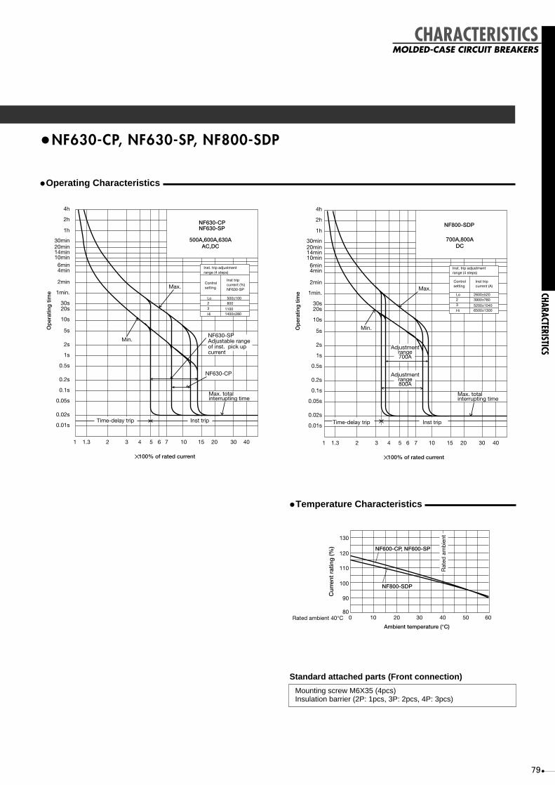
79
CHARACTERISTICS
•NF630-CP, NF630-SP, NF800-SDP
•Operating Characteristics
✕ 100% of rated current
Op
erat
ing
tim
e
Min.
Max.
NF630-CPNF630-SP
1
0.01s
1min.
1h
0.02s
0.05s
0.1s
0.2s
0.5s
1s
2s
5s
10s
20s30s
2min
4min6min
10min14min20min30min
2h
4h
1.3 2 3 4 5 6 7 10 15 20 30 40
Max. totalinterrupting time
NF630-SPAdjustable rangeof inst. pick upcurrent
Inst. trip adjustmentrange (4 steps)
Controlsetting
Inst tripcurrent (%)NF630-SP
Lo23
Hi
500±100800
11001400±280
500A,600A,630AAC,DC
NF630-CP
Time-delay trip Inst trip Time-delay trip Inst trip
Op
erat
ing
tim
e
Min.
Max.
NF800-SDP
0.01s
1min.
1h
0.02s
0.05s
0.1s
0.2s
0.5s
1s
2s
5s
10s
20s30s
2min
4min6min
10min14min20min30min
2h
4h
Max. totalinterrupting time
Inst. trip adjustmentrange (4 steps)
Controlsetting
Inst tripcurrent (A)
Lo23
Hi
2600±5203900±780
5200±10406500±1300
700A,800ADC
Adjustmentrange700A
Adjustmentrange800A
✕ 100% of rated current
1 1.3 2 3 4 5 6 7 10 15 20 30 40
CHARACTERISTICSMOLDED-CASE CIRCUIT BREAKERS
•Temperature Characteristics
Ambient temperature (°C)
Rated ambient 40°C
Rat
ed a
mb
ient
80
90
100
110
120
130
0 10 20 30 40 50 60
NF600-CP, NF600-SP
NF800-SDP
Cur
rent
rat
ing
(%)
Standard attached parts (Front connection)
Mounting screw M6X35 (4pcs)Insulation barrier (2P: 1pcs, 3P: 2pcs, 4P: 3pcs)

80
CHARACTERISTICS
CHARACTERISTICS
MOLDED-CASE CIRCUIT BREAKERS
MCCBS
•NF630-SEP, NF630-HEP, NF630-REP, NF800-CEP, NF800-SEP,NF800-HEP, NF800-REP
•Operating Characteristics
Instantaneous tripping current (✕ 100% of In)Current (✕ 100% of Ir)
LTD operating timeat 125%
1000s(TL=150s set) 670s(TL=100s set) 400s(TL= 60s set) 80s(TL= 12s set)
0.6 0.7 1 1.3 2 3 4 5 6 7 10 30 402015
0.01s
0.02s
0.05s
0.1s
0.2s
0.5s
1s
2s
5s
10s
20s30s
1min
2min
4min6min
10min14min20min30min
1h
2h
5h
10h
Pre-alarmpickup current IpIr x(0.70-0.75-0.8-0.85-0.9 ±10%-0.95-1.0)
Pre-alarmoperating time Tp
±20%
(at 200%)
Tp=2TL
Op
erat
ing
tim
e
INST pickup current IIx4~x15 ±15%
(Magnification to In)
Max. totalbreaking time
STD operating time Ts
STD pickup current Is
12-60-100-150s ±20%(at 200%)
Ir x(2-2.5-3-3.5-4 -5-6-7-8-10) ±15%
0.3 ± 0.06s0.2 ± 0.04s
0.1 ± 0.03s0.06 ± 0.02s
LTD operating time TL
NF630-SEPNF630-HEPNF630-REP
Note)Current setting Ir: 300~630A (Adjustable)
Rated Current In: 630A
LTD operating timeat 125%
1000s(TL=150s set) 670s(TL=100s set) 400s(TL= 60s set) 80s(TL= 12s set)
Pre-alarmpickup current IpIr x(0.70-0.75-0.8-0.85-0.9 ±10% -0.95-1.0)
Pre-alarmoperating time Tp
±20%
(at 200%)
Tp=2TL
INST pickup current IIx4~x12 ±15%
(Magnification to In)
Max. totalbreaking time
STD operating time Ts
STD pickup current Is
12-60-100-150s ±20%(at 200%)
Ir x(2-2.5-3-3.5-4 -5-6-7-8-10) ±15%
0.3 ± 0.06s0.2 ± 0.04s
0.1 ± 0.03s0.06 ± 0.02s
LTD operating time TL
0.01s
0.02s
0.05s
0.1s
0.2s
0.5s
1s
2s
5s
10s
20s30s
1min
2min
4min6min
10min14min20min30min
1h
2h
5h
10h
Op
erat
ing
tim
e
NF800-CEPNF800-SEPNF800-HEPNF800-REP
Note)Current setting Ir: 400~800A (Adjustable)
Rated Current In: 800A
Instantaneous tripping current (✕ 100% of In)Current (✕ 100% of Ir)
0.6 0.7 1 1.3 2 3 4 5 6 7 10 30 402015
•Temperature Characteristics
Ambient temperature (°C)
Rat
ed a
mb
ient
80
70
90
100
110
120
130
0 10 20 30 40 50 60
Co
ntin
uous
load
cur
rent
(%)
Standard attached parts (Front connection)
Mounting screw : M6X35, Insulation barrier (3P: 2pcs, 4P: 3pcs)

81
•NF630-UEP, NF800-UEP
•Operating Characteristics
LTD operating timeat-125%
1000s(TL=150s set) 670s(TL=100s set) 400s(TL= 60s set) 80s(TL= 12s set)
Pre-alarmpickup current IpIr x(0.70-0.75-0.8-0.85-0.9 ±10%-0.95-1.0)
Pre-alarmoperating time Tp
±20%
(at 200%)
Tp=2TL
INST pickup current IIx4~x15 ±15%
(Magnification to In)
Max. totalbreaking time
STD operating time Ts
STD pickup current Is
12-60-100-150s ±20%(at 200%)
Ir x(2-2.5-3-3.5-4 -5-6-7-8-10) ±15%
0.3 ± 0.06s0.2 ± 0.04s
0.1 ± 0.03s0.06 ± 0.02s
LTD operating time TL
0.01s
0.02s
0.05s
0.1s
0.2s
0.5s
1s
2s
5s
10s
20s30s
1min
2min
4min6min
10min14min20min30min
1h
2h
5h
10h
Op
erat
ing
tim
e
NF630-UEP
Note)Current setting Ir: 300~630A (Adjustable)
Rated Current In: 630A
Instantaneous tripping current (✕ 100% of In)Current (✕ 100% of Ir)
0.6 0.7 1 1.3 2 3 4 5 6 7 10 30 402015
LTD operating timeat-125%
1000s(TL=150s set) 670s(TL=100s set) 400s(TL= 60s set) 80s(TL= 12s set)
Pre-alarmpickup current IpIr x(0.70-0.75-0.8-0.85-0.9 ±10%-0.95-1.0)
Pre-alarmoperating time Tp
±20%
(at 200%)
Tp=2TL
INST pickup current IIx4~x12 ±15%
(Magnification to In)
Max. totalbreaking time
STD operating time Ts
STD pickup current Is
12-60-100-150s ±20%(at 200%)
Ir x(2-2.5-3-3.5-4 -5-6-7-8-10) ±15%
0.3 ± 0.06s0.2 ± 0.04s
0.1 ± 0.03s0.06 ± 0.02s
LTD operating time TL
0.01s
0.02s
0.05s
0.1s
0.2s
0.5s
1s
2s
5s
10s
20s30s
1min
2min
4min6min
10min14min20min30min
1h
2h
5h
10h
Op
erat
ing
tim
e
NF800-UEP
Note)Current setting Ir: 400~800A (Adjustable)
Rated Current In: 800A
Instantaneous tripping current (✕ 100% of In)Current (✕ 100% of Ir)
0.6 0.7 1 1.3 2 3 4 5 6 7 10 30 402015
•Temperature Characteristics
Ambient temperature (°C)
Rat
ed a
mb
ient
80
70
90
100
110
120
130
0 10 20 30 40 50 60
Co
ntin
uous
load
cur
rent
(%)
Standard attached parts (Front connection)
Mounting screw 3P: M6X35, M6x132 (2pcs each) 4P: M6x35 (3pcs), M6x132 (2pcs)Insulation barrier (3P: 2pcs, 4P: 3pcs)
CHARACTERISTICS
CHARACTERISTICSMOLDED-CASE CIRCUIT BREAKERS

82
CHARACTERISTICS
CHARACTERISTICS
MOLDED-CASE CIRCUIT BREAKERS
MCCBS
•NF1000-SS, NF1250-SS
•Operating Characteristics
40s1min
2min
4min6min
10min
20min
Maximum
Short-time pickup currentajustment range
For 1000A rated current
For 500Arated current
Minimum
Unlatching time
30min
20s
10s
6s4s
2s
1s0.6s0.4s
0.2s
0.1s
0.06s0.04s
0.02s
0.01s
30s
40min1h
2h3h
Op
erat
ing
tim
e
Current (✕ 100% of rated current)
1 1.25 2 3 5 10 4020
Max. total interrupting time
Rated current 500,600,700,800,900,1000A adjustableShort-time pickupcurrent adjustable
500% ± 50% 750% ± 75%1000% ± 100%
inst, pickup current
20KA Fixed
TypeNF1000-SS
AC
+4kA-2kA
40s1min
2min
4min6min
10min
20min
Maximum
Short-time pickup currentajustment range
For 1250A rated current
For 600A ratedcurrent
Minimum
Unlatching time
30min
20s
10s
6s4s
2s
1s0.6s0.4s
0.2s
0.1s
0.06s0.04s
0.02s
0.01s
30s
40min1h
2h3h
Op
erat
ing
tim
e
Current (✕ 100% of rated current)
1 1.25 2 3 5 10 4020
Max. total interrupting time
Rated current 600, 700,800, 1000, 1200A, 1250adjustableShort-time pickupcurrent adjustable
500% ± 50% 750% ± 75%1000% ± 100%
inst, pickup current
20KA Fixed
TypeNF1250-SS
AC+4kA-2kA
•Temperature Characteristics
Standard attached parts (Front connection)
Mounting screw M8X40 (4pcs) Insulation barrier (3P: 2pcs, 4P: 3pcs)Extention handle (1pc)
Ambient temperature (°C)
Rat
ed a
mb
ient
80
70
90
100
110
120
130
0 10 20 30 40 50 60
Co
ntin
uous
load
cur
rent
(%)

83
CHARACTERISTICS
CHARACTERISTICSMOLDED-CASE CIRCUIT BREAKERS
•NF1000-SSD, NF1250-SSD
•Operating Characteristics
6s4s
2s
1s
3h2h
1h40min
20min
10min6min4min
2min
1min40s30s20s
10s
0.6s0.4s
0.2s
0.1s0.06s0.0.4s
0.02s
0.01s
Type NF1000-SSD 1000A DC
Op
erat
ing
tim
e
Current (✕ 100% of rated current)
1 1.25 2 3 4 5 7 10 20 30 5040 70
Maximum
Inst. trip adjustment range(4 steps)
Max. totalinterrupting time
Controlsetting
L023
Hi
Inst. tripcurrent(A)
Minimum
2800 ± 7004200 ± 7005600 ± 7007000 ± 700
Timedelay trip
Inst. trip
6s4s
2s
1s
3h2h
1h40min
20min
10min6min4min
2min
1min40s30s20s
10s
0.6s0.4s
0.2s
0.1s
0.06s0.0.4s
0.02s
0.01s
Type NF1250-SSD 1250A DC
Op
erat
ing
tim
e
Current (✕ 100% of rated current)
1 1.25 2 3 4 5 7 10 20 30 5040 70
Maximum
Inst. trip adjustment range(4 steps)
Max. totalinterrupting time
Controlsetting
L023
Hi
Inst. tripcurrent(A)
Minimum
2800 ± 7004200 ± 7005600 ± 7007000 ± 700
Timedelay trip
Inst. trip
•Ambient Compensation
Standard attached parts (Front connection)
Mounting screw M8X40 (4pcs) Insulation barrier (2P: 1pc, 3P: 2pcs, 4P: 3pcs)Extention handle (1pc)
Ambient temperature (°C)
Cur
rent
rat
ing
(%)
1080
90
100
110
120
130
20 30 40 50 605
Rat
ed a
mb
ient
1000A
1200A

84
CHARACTERISTICS
CHARACTERISTICS
MOLDED-CASE CIRCUIT BREAKERS
MCCBS
•NF1250-UR
•Operating Characteristics
3h2h
1h
Current (✕ 100% of rated current)
1 1.25 2 3 4 5 7 10 20 30 6040
40min
20min30min
10min6min4min
2min
1min40s30s20s
10s
0.6s0.4s
0.2s
0.1s0.06s0.0.4s
0.02s
0.01s
Op
erat
ing
tim
e
6s4s
2s
1s
Short-time pickup currentadjustment range
Maximum
Minimum
Unlatching timeMaximum total interrupting time
For 1250A rated current
For 600A rated current
Rated current 600,700,800,1000,1200,1250A adjustableShort-time pickupcurrent adjustable
500% ± 50% 750% ± 75%1000% ± 100%
inst. pickup current adjustable
20kA Fixed
TypeNF1250-UR
+4kA-2kA
•Temperature Characteristics
Standard attached parts (Front connection)
Mounting screw M8X40 (4pcs) Insulation barrier (3P: 2pcs, 4P: 3pcs)Extention handle (1pc)
Ambient temperature (°C)
Rat
ed a
mb
ient
80
70
90
100
110
120
130
0 10 20 30 40 50 60
Co
ntin
uous
load
cur
rent
(%)

85
CHARACTERISTICS
CHARACTERISTICSMOLDED-CASE CIRCUIT BREAKERS
•NF1600-SS, NF1600-SSD
•Operating Characteristics
40s1min
2min
4min6min
10min
20min
Maximum
Short-time pickup currentadjustment range
For 1600A rated current
For 800A rated current
Minimum
Unlatching time
30min
20s
10s
6s4s
2s
1s0.6s0.4s
0.2s
0.1s
0.06s0.04s
0.02s
0.01s
30s
40min1h
2h3h
Op
erat
ing
tim
e
Current (✕ 100% of rated current)
1 2 3 4 5 7 10 6030 4020
Max. total interrupting time
Rated current 800, 1000,1200, 1400, 1500, 1600AadjustableShort-time pickupcurrent adjustable
300% ± 30% 450% ± 45% 600% ± 60%
inst, pickup current
20kA Fixed
TypeNF1000-SS
AC
+4kA-2kA
Type CType B Type D
1.131 21.45 3 4 5 6 7 10 30 402015
0.01s
0.02s
0.05s
0.1s
0.2s
0.5s
1s
2s
5s
10s
20s30s
1min
2min
4min6min
10min14min20min30min
1h
2h
4h
✕ 100% of rated current
Op
erat
ing
tim
e
Operating CharacteristicsType:BH-PSRated Current:5~60AAmb. temp.:40°C
Min.
Max.
•Temperature Characteristics
Standard attached parts (Front connection)
Mounting screw M8X45 (4pcs) Insulation barrier (2P: 1pc, 3P: 2pcs, 4P: 3pcs)Extention handle (1pc)
Ambient temperature (°C)
Rat
ed a
mb
ient
80
70
90
100
110
120
130
0 10 20 30 40 50 60
Co
ntin
uous
load
cur
rent
(%)

86
ELCBS
CHARACTERISTICSEARTH-LEAKAGE CIRCUIT BREAKERS
•NV30-CS, NV30-SP, NV50-CP, NV60-CP, NV50-HP, NV60-HP, MN30-CS, MN50-CP, MN50-SP
•Operating Characteristics
x100% of rated current
Min.
Max.
Type NV30-CS
Operating Characteristics
1
0.01s
0.006s
0.02s
0.06s0.04s
0.1s
0.2s
0.6s0.4s
1s
2s
4s6s
10s
20s30s40s
1min
2min
4min6min
10min
20min
40min1h
2h3h
1.3 2 3 4 5 7 10 20 50 70 1004030
Op
erat
ing
tim
eO
per
atin
g t
ime
x100% of rated current
Min.
Max.
NV50-CPNV50-HP
NV30-SPNV60-CPNV60-HP
1
0.01s
0.02s
0.05s
0.1s
0.2s
0.5s
1s
2s
5s
10s
20s30s
1min
2min
4min6min
10min14min20min30min
1h
2h
4h
1.3 2 3 4 5 6 7 10 15 20 30 40
x100% of rated current
Min.
Max.
Type MN30-CS
Operating Characteristics
1
0.01s
0.006s
0.02s
0.06s0.04s
0.1s
0.2s
0.6s0.4s
1s
2s
4s6s
10s
20s30s40s
1min
2min
4min6min
10min
20min
40min1h
2h3h
1.25 2 3 4 5 7 10 20 50 70 1004030
Op
erat
ing
tim
eO
per
atin
g t
ime
Min.
Max.
MN50-CPMN50-SP
1
0.01s
1min
1h
0.02s
0.05s
0.1s
0.2s
0.5s
1s
2s
5s
10s
20s30s
2min
4min6min
10min14min20min30min
2h
4h
1.25 2 3 4 5 6 7 10 15 20 30 40
✕ 100% of rated current
CHARACTERISTICS
(JIS)(IEC)
-55
010
7080
100
150
200250300
1020
2030
3040
4050
5060
(MN30-CS, MN50-CP, MN50-SP)Ambient temperature (°C)
Op
erat
ing
tim
e ch
ang
e ra
te (%
)
Rat
ed a
mb
ient
•Temperature Characteristics•Earth-Leakage Tripping Characteristics
Leakage current(% of rated current sensitivity)
4
2
1h
3020
1064
2
1min
3020
10
1s
0.5
0.2
0.1
0.05
0.020.01s
25 50 100 500
Op
erat
ing
tim
e
5
2
Rat
ed n
on-o
per
atin
g cu
rren
t se
nsiti
vity
Rat
ed c
urre
nt s
ensi
tivity
Leakage current(% of rated current sensitivity)
25
0.01s0.02
0.05
0.1
0.2
0.5
1s
2
5
10
2030
1min
2
46
10
2030
1h
2
4
50 100 500
Rat
ed n
on-o
per
atin
g cu
rren
t se
nsiti
vity
Rat
ed c
urre
nt s
ensi
tivity
Op
erat
ing
tim
e
Standard attached parts (Front connection)NV30-CS, MN30-CS
Mounting screw M4x0.7x20 (2pcs)
NV30-SP, NV50-CP/HP, NV60-CP/HP, MN50-CP/SP
Mounting screw M4x0.7x35 (2pcs)Insulation barrier (2pcs Exception for NV50-CP, NV60-CP,MN50-CP)

87
•NV100-CP, NV100-SP, NV100-HP, MN100-SP
•Operating Characteristics
Op
erat
ing
tim
e
x100% of rated current
Time delay trip Instantaneous trip
Min.
Max.
NV100-SPNV100-HP
15A~30A15A~30A
1
0.01s0.02s
0.05s
0.1s
0.2s
0.5s
1s
2s
5s
10s
20s30s
1min
2min
4min6min
10min14min20min30min
1h
2h
4h
1.3 2 3 4 5 6 7 10 15 20 30 40X100% of rated current
MN100-SP 45A~100A
1 1.25 2 3 4 5 6 7 10 15 20 30 40
Min.
Max. (60A~100A)
Max. (40A,50A)
Time-delay trip Instantaneous tripO
per
atin
g t
ime
0.01s0.02s
0.05s
0.1s
0.2s
0.5s
1s
2s
5s
10s
20s30s
1min
2min
4min6min
10min14min20min30min
1h
2h
4hO
per
atin
g t
ime
x100% of rated current
Time delay trip Instantaneous trip
Min.
Max.(60A-100A)
Max.(40A, 50A)
NV100-SPNV100-HP
40A~100A40A~100A60A~100ANV100-CP
1
0.01s0.02s
0.05s
0.1s
0.2s
0.5s
1s
2s
5s
10s
20s30s
1min
2min
4min6min
10min14min20min30min
1h
2h
4h
1.3 2 3 4 5 6 7 10 15 20 30 40
•Earth-Leakage Tripping Characteristics
Leakage current(% of rated current sensitivity)
Op
erat
ing
tim
e
4
2
1h
30
1420
1064
2
1min
3020
10
1s
0.5
0.2
0.1
0.05
0.02
0.01s
5
2
25 50100 500
Rat
ed c
urre
nt s
ensi
tivity
High-speedtype
Rat
ed n
on-o
per
atin
g cu
rren
t se
nsiti
vity
4
2
1h
3020
1064
2
1min
3020
10
1s
0.5
0.2
0.1
0.05
0.02
0.01s
5
2
25 50100 500
Rat
ed c
urre
nt s
ensi
tivity
Rat
ed n
on-o
per
atin
g cu
rren
t se
nsiti
vity
500 10000 500 10000 500 10000100025 50100
Rat
ed c
urre
nt s
ensi
tivity
Rat
ed n
on-o
per
atin
g cu
rren
t se
nsiti
vity
Inertialnonoperating-time
100025 50100
Rat
ed c
urre
nt s
ensi
tivity
Rat
ed n
on-o
per
atin
g cu
rren
t se
nsiti
vity
Inertialnonoperating-time
25 50100 1000
Rat
ed c
urre
nt s
ensi
tivity
Time-delay type0.45s(MAX)
Time-delay type1s(MAX)
Time-delay type2s(MAX)
Rat
ed n
on-o
per
atin
g cu
rren
t se
nsiti
vity
Inertialnonoperating-timeInertialnonoperating-time
(JIS)(IEC)
•Temperature Characteristics
Standard attached parts (Front connection)
Mounting screw M4x0.7x35 (2pcs)Insulation barrier (2pcs)
Ambient temperature (°C)
Cur
rent
rat
ing
(%)
Rat
edam
bie
nt
-55
80
90
100
110
120
130
15~30A
40~100A
010
1020
2030
3040
4050 (MN100-SP)
CHARACTERISTICS
CHARACTERISTICSEARTH-LEAKAGE CIRCUIT BREAKERS

88
•NV100-SEP, NV100-HEP
•Operating Characteristics
0.6 0.7 1 1.3 2 3 4 5 6 7 10 30 402015
0.01s
0.02s
0.05s
0.1s
0.2s
0.5s
1s
2s
5s
10s
20s30s
1min
2min
4min6min
10min14min20min30min
1h
2h
4h
Pre-alarmpickup current IpIr x (0.70-0.75-0.8-0.85-0.9-0.95-1.0) ±10%
Pre-alarmoperating time Tp
±20%
(at 200%)
Tp=2TL
Current setting (✕ 100% of Ir)x 100% of rated current
Op
erat
ing
tim
e
Instantaneous tripping current (✕ 100% of In)
INST pickup current Iix 4 ~ x16 ±15%
(Magnification to Rated current)
Max. total breaking time
STD operating time Ts
STD pickup current IsIr x (2-2.5-3-3.5-4- 5-6-7-8-10) ±15%
0.3 ± 0.06 s0.2 ± 0.04 s
0.1 ± 0.03 s0.06 ± 0.02 s
NV 100-SEP NV 100-HEPNote )
Current setting Ir Rated current In
12-60-80-100s ±20%(at 200%)
LTD operating time TL
Note
20A50A100A
15~20A30~50A60~100A(Adjustable)
•Temperature Characteristics•Earth-Leakage Tripping Characteristics
Leakage current(% of rated current sensitivity)
Op
erat
ing
tim
e
4
2
1h
30
1420
1064
2
1min
3020
10
1s
0.5
0.2
0.1
0.05
0.02
0.01s
5
2
25 50100 500
Rat
ed c
urre
nt s
ensi
tivity
High-speedtype
Rat
ed n
on-o
per
atin
g cu
rren
t se
nsiti
vity
500 10000 500 10000 500 10000100025 50100
Rat
ed c
urre
nt s
ensi
tivity
Time-delaytype 2s(MAX.)
Rat
ed n
on-o
per
atin
g cu
rren
t se
nsiti
vity
Inertialnonoperating-time
100025 50100
Rat
ed c
urre
nt s
ensi
tivity
Time-delaytype 1s(MAX.)
Rat
ed n
on-o
per
atin
g cu
rren
t se
nsiti
vity
Inertialnonoperating-time
25 50100 1000
Rat
ed c
urre
nt s
ensi
tivity
Time-delaytype 0.45s(MAX.)
Rat
ed n
on-o
per
atin
g cu
rren
t se
nsiti
vity
Inertialnonoperating-timeInertialnonoperating-time
(IEC)
Standard attached parts (Front connection)
Mounting screw M4x0.7x35 (3P: 2pcs, 4P: 4pcs)Insulation barrier (3P: 2pcs, 4P: 3pcs)
Ambient temperature (°C)
80
70
90
100
110
120
130
0 10 20 30 40 50 60
Co
ntin
uous
load
cur
rent
(%)
Rat
ed a
mb
ient
ELCBS
CHARACTERISTICSEARTH-LEAKAGE CIRCUIT BREAKERS
CHARACTERISTICS

89
CHARACTERISTICS
CHARACTERISTICSEARTH-LEAKAGE CIRCUIT BREAKERS
•NV225-CP, NV225-SP, NV225-HP, MN225-SP
•Operating Characteristics
Op
erat
ing
tim
e
x100% of rated current
Time delay trip Instantaneous trip
Min.
Max. totalInterrupting time
Max.
NV225-CPNV225-SPNV225-HP
1
0.01s0.02s
0.05s
0.1s
0.2s
0.5s
1s
2s
5s
10s
20s30s
1min
2min
4min6min
10min14min20min30min
1h
2h
4h
1.3 2 3 4 5 6 7 10 15 20 30 40
Leakage current(% of rated current sensitivity)
Op
erat
ing
tim
e
4
2
1h
30
1420
1064
2
1min
3020
10
1s
0.5
0.2
0.1
0.05
0.02
0.01s
5
2
25 50100 500
Rat
ed c
urre
nt s
ensi
tivity
High-speedtype
Rat
ed n
on-o
per
atin
g cu
rren
t se
nsiti
vity
4
2
1h
3020
1064
2
1min
3020
10
1s
0.5
0.2
0.1
0.05
0.02
0.01s
5
2
25 50100 500
Rat
ed c
urre
nt s
ensi
tivity
Rat
ed n
on-o
per
atin
g cu
rren
t se
nsiti
vity
500 10000 500 10000 500 10000100025 50100
Rat
ed c
urre
nt s
ensi
tivity
Rat
ed n
on-o
per
atin
g cu
rren
t se
nsiti
vity
Inertialnonoperating-time
100025 50100
Rat
ed c
urre
nt s
ensi
tivity
Rat
ed n
on-o
per
atin
g cu
rren
t se
nsiti
vity
Inertialnonoperating-time
25 50100 1000
Rat
ed c
urre
nt s
ensi
tivity
Time-delay type0.45s(MAX)
Time-delay type1s(MAX)
Time-delay type2s(MAX)
Rat
ed n
on-o
per
atin
g cu
rren
t se
nsiti
vity
Inertialnonoperating-timeInertialnonoperating-time
Min.
Max.
MN225-SP
1
0.01s
1min
1h
0.02s
0.05s
0.1s
0.2s
0.5s
1s
2s
5s
10s
20s30s
2min
4min6min
10min14min20min30min
2h
4h
1.25 2 3 4 5 6 7 10 15 20 30 40
Max. totalinterruptingtime
Time-delay trip Instantaneous trip
x100% of rated current
Op
erat
ing
tim
e
•Temperature Characteristics
Ambient temperature (°C)(rated ambient 30°C)
Cur
rent
rat
ing
(%)
Rat
ed a
mb
ient
80
90
100
110
120
130
010
1020
2030
3040
4050
5060 (MN225-SP)
-55
•Earth-Leakage Tripping Characteristics
(JIS)(IEC)
Standard attached parts (Front connection)
Mounting screw M4x0.7x55 (2pcs)Insulation barrier (4pcs)

ELCBS
90
CHARACTERISTICS
CHARACTERISTICS
EARTH-LEAKAGE CIRCUIT BREAKERS
•NV225-SEP, NV225-HEP
•Operating Characteristics
•Temperature Characteristics
Ambient temperature (°C)
80
70
90
100
110
120
130
0 10 20 30 40 50 60
Co
ntin
uous
load
cur
rent
(%)
Rat
ed a
mb
ient
•Earth-Leakage Tripping Characteristics
(IEC)
Standard attached parts (Front connection)
Mounting screw M4x0.7x55 (3P: 2pcs, 4P: 4pcs)Insulation barrier (3P: 4pcs, 4P: 6pcs)
0.6 0.7 1 1.3 2 3 4 5 6 7 10 30 402015
0.01s
0.02s
0.05s
0.1s
0.2s
0.5s
1s
2s
5s
10s
20s30s
1min
2min
4min6min
10min14min20min30min
1h
2h
4h
Pre-alarmpickup current IpIr x (0.70-0.75-0.8-0.85-0.9-0.95-1.0) ±10%
Pre-alarmoperating time Tp
±20%
(at 200%)
Tp=2TL
Current setting (✕ 100% of Ir)
x 100% of rated current
Op
erat
ing
tim
e
Instantaneous tripping current (✕ 100% of In)
INST pickup current Iix 4 ~ x16 ±15%
(Magnification to Rated current)
Max. total breaking time
STD operating time Ts
STD pickup current IsIr x (2-2.5-3-3.5-4- 5-6-7-8-10) ±15%
0.3 ± 0.06 s0.2 ± 0.04 s
0.1 ± 0.03 s0.06 ± 0.02 s
NV225-SEP NV225-HEP
Note )
Current setting Ir Rated current In
12-60-80-100s ±20%(at 200%)
LTD operating time TL
Note
225A125~225A
(Adjustable)
Leakage current(% of rated current sensitivity)
Op
erat
ing
tim
e
4
2
1h
30
1420
1064
2
1min
3020
10
1s
0.5
0.2
0.1
0.05
0.02
0.01s
5
2
25 50100 500
Rat
ed c
urre
nt s
ensi
tivity
High-speedtype
Rat
ed n
on-o
per
atin
g cu
rren
t se
nsiti
vity
500 10000 500 10000 500 10000100025 50100
Rat
ed c
urre
nt s
ensi
tivity
Time-delaytype 2s(MAX.)
Rat
ed n
on-o
per
atin
g cu
rren
t se
nsiti
vity
Inertialnonoperating-time
100025 50100
Rat
ed c
urre
nt s
ensi
tivity
Time-delaytype 1s(MAX.)
Rat
ed n
on-o
per
atin
g cu
rren
t se
nsiti
vity
Inertialnonoperating-time
25 50100 1000
Rat
ed c
urre
nt s
ensi
tivity
Time-delaytype 0.45s(MAX.)
Rat
ed n
on-o
per
atin
g cu
rren
t se
nsiti
vity
Inertialnonoperating-timeInertialnonoperating-time

91
Time-delay trip Instantaneous trip
Op
erat
ing
tim
e
✕ 100% of rated current
Max.
Min.
NV400-CPNV400-SP
1
0.01s
1min
1h
0.02s
0.05s
0.1s
0.2s
0.5s
1s
2s
5s
10s
20s30s
2min
4min6min
10min14min20min30min
2h
4h
1.3 2 3 4 5 6 7 10 15 20 30 40
Max. totalinterrupting time
NV400-CP
NV400-SP
•NV400-CP, NV400-SP
•Operating Characteristics
•Temperature Characteristics
080
90
100
110
120
130
10 20 30 40 50 60
Ambient temperature (°C)Rated ambient 40°C
Rat
ed a
mb
ient
Cur
rent
rat
ing
(%)
•Earth-Leakage Tripping Characteristics
Leakage current (% of rated current sensitivity)
25
0.01s
0.02s
0.04s
0.1s
0.2s
0.5s
1s
2s
5s
10s
30s
1min2min4min
10min
30min
1h
2h4h
50 100 500 25 50 100 500 1000
Rat
ed n
onop
erat
ing
curr
ent
Rat
ed n
onop
erat
ing
curr
ent
Rat
ed c
urre
nt s
ensi
tivity
Rat
ed c
urre
nt s
ensi
tivity
25 50 100 500 1000
Rat
ed n
onop
erat
ing
curr
ent
Rat
ed c
urre
nt s
ensi
tivity
Op
erat
ing
tim
e
High-speedtype
Time-delay type0.45s. (MAX)
Time-delay type1s. (MAX)
Inertialnonoperating time
Inertialnonoperating time
25 50 100 500 1000
Rat
ed n
onop
erat
ing
curr
ent
Rat
ed c
urre
nt s
ensi
tivity
Time-delay type2s. (MAX)
Inertialnonoperating time
Standard attached parts (Front connection)
Mounting screw M6X60 (4pcs) Insulation barrier (3P: 4pcs, 4P: 6pcs)
CHARACTERISTICS
CHARACTERISTICSEARTH-LEAKAGE CIRCUIT BREAKERS

92
0.6 0.7 1 1.3 2 3 4 5 6 7 10 30 402015
0.01s
0.02s
0.05s
0.1s
0.2s
0.5s
1s
2s
5s
10s
20s 30s
1min
2min
4min6min
10min14min20min30min
1h
2h
5h
10h
Pre-alarmpickup current IpIr x (0.70-0.75-0.8-0.85-0.9-0.95-1.0) ±10%
Pre-alarmoperating time Tp
±20%
(at 200%)
Tp=2TL
Current setting (✕ 100% of Ir)✕ 100% of rated current
Op
erat
ing
tim
e
Instantaneous tripping current (✕ 100% of In)
INST pickup current IIx 4 ~ x16 ±15%
(Magnification to In)
Max. totalbreaking time
STD operating time Ts
STD pickup current IsIr x (2-2.5-3-3.5-4- 5-6-7-8-10) ±15%
0.3 ± 0.06 s0.2 ± 0.04 s
0.1 ± 0.03 s0.06 ± 0.02 s
NV400-SEPNV400-HEPNV400-REP
Note )Rated current In: 400A
12-60-100-150s ±20%(at 200%)
1000s (TL=150s set)670s (TL=100s set)400s (TL= 60s set)80s (TL= 12s set)
LTD operating time TL
LTD operating time at 125%
(Adjustable)
Current setting Ir: 200-400A
•NV400-SEP, NV400-HEP, NV400-REP
•Operating Characteristics
•Temperature Characteristics
Ambient temperature (°C)
Rat
ed a
mb
ient
80
70
90
100
110
120
130
0 10 20 30 40 50 60
Co
ntin
uous
load
cur
rent
(%)
•Earth-Leakage Tripping Characteristics
Leakage current (% of rated current sensitivity)
25
0.01s
0.02s
0.04s
0.1s
0.2s
0.5s
1s
2s
5s
10s
30s
1min2min4min
10min
30min
1h
2h4h
50 100 500 25 50 100 500 1000
Rat
ed n
onop
erat
ing
curr
ent
Rat
ed n
onop
erat
ing
curr
ent
Rat
ed c
urre
nt s
ensi
tivity
Rat
ed c
urre
nt s
ensi
tivity
25 50 100 500 1000
Rat
ed n
onop
erat
ing
curr
ent
Rat
ed c
urre
nt s
ensi
tivity
Op
erat
ing
tim
e
High-speedtype
Time-delay type0.45s. (MAX)
Time-delay type1s. (MAX)
Inertialnonoperating time
Inertialnonoperating time
25 50 100 500 1000
Rat
ed n
onop
erat
ing
curr
ent
Rat
ed c
urre
nt s
ensi
tivity
Time-delay type2s. (MAX)
Inertialnonoperating time
Standard attached parts (Front connection)
Mounting screw M6X60 (4pcs) Insulation barrier (3P: 4pcs, 4P: 6pcs)
CHARACTERISTICS
CHARACTERISTICS
EARTH-LEAKAGE CIRCUIT BREAKERS
ELCBS

93
•NV630-CP, NV630-SP
•Operating Characteristics
Time-delay trip Inst trip
Op
erat
ing
tim
e
Min.
Max.
NV630-CPNV630-SP
0.01s
1min.
1h
0.02s
0.05s
0.1s
0.2s
0.5s
1s
2s
5s
10s
20s30s
2min
4min6min
10min14min20min30min
2h
4h
Max. totalinterrupting time
NV630-SPAdjustable rangeof inst. pick upcurrent
Inst. trip adjustmentrange (4 steps)
Controlsetting
Inst tripcurrent (%)NV630-SP
Lo23
Hi
400±80600
8001000±200
500A,600A,630A
NV630-CP
✕ 100% of rated current
1 1.3 2 3 4 5 6 7 10 15 20 30 40
•Temperature Characteristics
0 1080
90
100
110
120
130
20 30 40 50 60
Cur
rent
rat
ing
(%)
Rat
edam
bie
nt
(rated ambient 40°C)
Leakage current (% of rated current sensitivity)
25
0.01s
0.02s
0.04s
0.1s
0.2s
0.5s
1s
2s
5s
10s
30s
1min2min4min
10min
30min
1h
2h4h
50 100 500 25 50 100 500 1000
Rat
ed n
onop
erat
ing
curr
ent
Rat
ed n
onop
erat
ing
curr
ent
Rat
ed c
urre
nt s
ensi
tivity
Rat
ed c
urre
nt s
ensi
tivity
25 50 100 500 1000
Rat
ed n
onop
erat
ing
curr
ent
Rat
ed c
urre
nt s
ensi
tivity
Op
erat
ing
tim
e
High-speedtype
Time-delay type0.45s. (MAX)
Time-delay type1s. (MAX)
Inertialnonoperating time
Inertialnonoperating time
25 50 100 500 1000
Rat
ed n
onop
erat
ing
curr
ent
Rat
ed c
urre
nt s
ensi
tivity
Time-delay type2s. (MAX)
Inertialnonoperating time
•Earth-Leakage Tripping Characteristics
Standard attached parts (Front connection)
Mounting screw M6x35 (4pcs)Insulation barrier (3P: 2pcs, 4P: 3pcs)
CHARACTERISTICS
CHARACTERISTICSEARTH-LEAKAGE CIRCUIT BREAKERS

94
•NV630-SEP, NV630-HEP, NV800-SEP, NV800-HEP
•Operating Characteristics
LTD operating timeat-125%
1000s(TL=150s set) 670s(TL=100s set) 400s(TL= 60s set) 80s(TL= 12s set)
0.01s
0.02s
0.05s
0.1s
0.2s
0.5s
1s
2s
5s
10s
20s30s
1min
2min
4min6min
10min14min20min30min
1h
2h
5h
10h
Pre-alarmpickup current IpIr x(0.70-0.75-0.8-0.85-0.9 ±10% -0.95-1.0)
Pre-alarmoperating time Tp
±20%
(at 200%)
Tp=2TL
Op
erat
ing
tim
e
INST pickup current IIx4~x10 ±15%
(Magnification to In)
Max. totalbreaking time
STD operating time Ts
STD pickup current Is
12-60-100-150s ±20%(at 200%)
Ir x(2-2.5-3-3.5-4 -5-6-7-8-10) ±15%
0.3 ± 0.06s0.2 ± 0.04s
0.1 ± 0.03s0.06 ± 0.02s
LTD operating time TL
NV630-SEPNV630-HEP
Note)Current setting Ir: 300~630A (Adjustable)
Rated Current In: 630A
Instantaneous tripping current (✕ 100% of In)Current (✕ 100% of Ir)
0.60.7 1 1.3 2 3 4 5 6 7 10 30 402015
LTD operating timeat-125%
1000s(TL=150s set) 670s(TL=100s set) 400s(TL= 60s set) 80s(TL= 12s set)
0.01s
0.02s
0.05s
0.1s
0.2s
0.5s
1s
2s
5s
10s
20s30s
1min
2min
4min6min
10min14min20min30min
1h
2h
5h
10h
Pre-alarmpickup current IpIr x(0.70-0.75-0.8-0.85-0.9 ±10%-0.95-1.0)
Pre-alarmoperating time Tp
±20%
(at 200%)
Tp=2TL
Op
erat
ing
tim
e
INST pickup current IIx4~x10 ±15%
(Magnification to In)
Max. totalbreaking time
STD operating time Ts
STD pickup current Is
12-60-100-150s ±20%(at 200%)
Ir x(2-2.5-3-3.5-4 -5-6-7-8-10) ±15%
0.3 ± 0.06s0.2 ± 0.04s
0.1 ± 0.03s0.06 ± 0.02s
LTD operating time TL
NV800-SEPNV800-HEP
Note)Current setting Ir: 400~800A (Adjustable)
Rated Current In: 800A
Instantaneous tripping current (✕ 100% of In)Current (✕ 100% of Ir)
0.60.7 1 1.3 2 3 4 5 6 7 10 30 402015
•Temperature Characteristics
Ambient temperature (°C)
Rat
ed a
mb
ient
80
70
90
100
110
120
130
0 10 20 30 40 50 60
Co
ntin
uous
load
cur
rent
(%)
•Earth-Leakage Tripping Characteristics
Standard attached parts (Front connection)
Mounting screw M6x35 (4pcs)Insulation barrier (3P: 2pcs, 4P: 3pcs)
CHARACTERISTICS
CHARACTERISTICS
EARTH-LEAKAGE CIRCUIT BREAKERS
ELCBS
Leakage current (% of rated current sensitivity)
25
0.01s
0.02s
0.04s
0.1s
0.2s
0.5s
1s
2s
5s
10s
30s
1min2min4min
10min
30min
1h
2h4h
50 100 500 25 50 100 500 1000
Rat
ed n
onop
erat
ing
curr
ent
Rat
ed n
onop
erat
ing
curr
ent
Rat
ed c
urre
nt s
ensi
tivity
Rat
ed c
urre
nt s
ensi
tivity
25 50 100 500 1000
Rat
ed n
onop
erat
ing
curr
ent
Rat
ed c
urre
nt s
ensi
tivity
Op
erat
ing
tim
e
High-speedtype
Time-delay type0.45s. (MAX)
Time-delay type1s. (MAX)
Inertialnonoperating time
Inertialnonoperating time
25 50 100 500 1000
Rat
ed n
onop
erat
ing
curr
ent
Rat
ed c
urre
nt s
ensi
tivity
Time-delay type2s. (MAX)
Inertialnonoperating time

95
•BH-D6
•Temperature Characteristics
Min.
Max.
Max totaltripping time
Tripping CharacteristicsType:BH-D6Rated Current:6A-63AAmb. temp.:30°C
0.6
0.002
0.0050.010.02
0.050.1
0.2
0.512
510203050
100
200
50010002000
500010000
sMin
0.7 1 1.13 1.45 2 3 4 5 6 7 10 15 20 30
1
2
5
10203050
100
200
✕ 100% of rated current
Trip
pin
g t
ime
B C
• Operating Characteristics
•BH BH-P
• Operating Characteristics
-10 -5 0
90
85
95
100
105
110
115120
125
130
135
5 10 15 20 25 30 35 40
Ambient temperature (°C)
Cur
rent
rat
ing
s (%
)
Rat
ed
amb
ient
1.131 21.45 3 4 5 6 7 10 30 402015
0.01s
0.02s
0.05s
0.1s
0.2s
0.5s
1s
2s
5s
10s
20s30s
1min
2min
4min6min
10min14min20min30min
1h
2h
4h
✕ 100% of rated current
Op
erat
ing
tim
e
Operating CharacteristicsType:BH, BH-PRated Current:70, 100AAmb. temp.:40°C
Min.
Max.
Ambient temperature (°C)
Cur
rent
rat
ing
(%)
85
95
105
115
125
135
90
100
110
120
130
140
0 10 30 4020 50 60
70, 100A
Rat
ed a
mb
ient
•Ambient Compensating Curve
•BV-D
Ground fault current (% of rated current sensitivity)
25
0.01s
0.02s
0.05s0.1s
0.2s
0.5s
1s
2s
5s
10s
30s20s
1min
2min4min
10min6min
30min20min
1h
2h
50 100 500
Op
erat
ing
tim
e
Rat
ed n
onop
erat
ing
curr
ent
sens
itivi
ty
Rat
ed c
urre
nt s
ensi
tivity
•Operating Characteristics
CHARACTERISTICS
CHARACTERISTICSMINIATURE CIRCUIT BREAKERS
MCB

96
Type CType B Type D
1.131 21.45 3 4 5 6 7 10 30 402015
0.01s
0.02s
0.05s
0.1s
0.2s
0.5s
1s
2s
5s
10s
20s30s
1min
2min
4min6min
10min14min20min30min
1h
2h
4h
✕ 100% of rated current
Op
erat
ing
tim
e
Operating CharacteristicsType:BH-SRated Current:5~60AAmb. temp.:40°C
Min.
Max.
Ambient temperature (°C)
Cur
rent
rat
ing
(%)
85
95
105
115
125
135
90
80
100
110
120
130
140
0 10 30 4020 50 60
40-60A5A
10A
15-25A30A
Rat
ed a
mb
ient
Type CType B Type D
1.131 21.45 3 4 5 6 7 10 30 402015
0.01s
0.02s
0.05s
0.1s
0.2s
0.5s
1s
2s
5s
10s
20s30s
1min
2min
4min6min
10min14min20min30min
1h
2h
4h
✕ 100% of rated current
Op
erat
ing
tim
e
Operating CharacteristicsType:BH-PSRated Current:5~60AAmb. temp.:40°C
Min.
Max.
Ambient temperature (°C)
Cur
rent
rat
ing
(%)
85
95
105
115
125
135
90
80
100
110
120
130
140
0 10 30 4020 50 60
6A, 30A, 32A50A, 60A
10A
15-20A, 40A
Rat
ed a
mb
ient
•Ambient Compensating Curve •Ambient Compensating Curve
•BH-S
•Operating Characteristics
•BH-PS
•Operating Characteristics
MCB
CHARACTERISTICS
CHARACTERISTICS
MINIATURE CIRCUIT BREAKERS
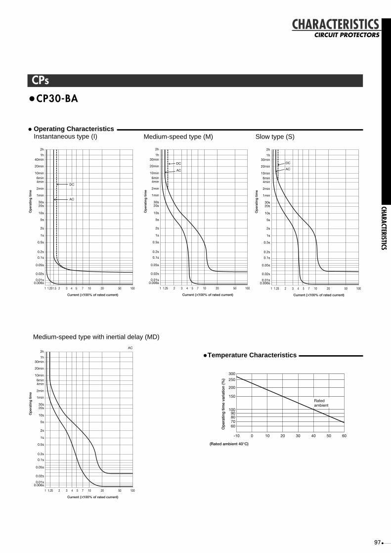
97
CPs
DC
AC
1
0.006s0.01s
0.02s
0.05s
0.1s
0.2s
0.5s
1s
2s
5s
10s
20s30s
1min
2min
4min6min
10min
20min
40min1h
2h
1.251.5 2 3 4 5 7 10 20 50 100
Current (✕ 100% of rated current)
Op
erat
ing
tim
e
DC
AC
1
0.006s0.01s
0.02s
0.05s
0.1s
0.2s
0.5s
1s
2s
5s
10s
20s30s
1min
2min
4min6min
10min
20min
30min1h
2h
1.25 2 3 4 5 7 10 20 50 100
Current (✕ 100% of rated current)
Op
erat
ing
tim
e
•CP30-BA
•Temperature CharacteristicsAC
1
0.006s0.01s
0.02s
0.05s
0.1s
0.2s
0.5s
1s
2s
5s
10s
20s30s
1min
2min
4min6min
10min
20min
30min1h
2h
1.25 2 3 4 5 7 10 20 50 100
Current (✕ 100% of rated current)
Op
erat
ing
tim
e
Ratedambient
(Rated ambient 40°C)
Op
erat
ing
tim
e va
riat
ion
(%)
-10
60708090
100
150
200
250
300
0 10 20 30 40 50 60
Medium-speed type (M)• Operating Characteristics
Instantaneous type (I)
Medium-speed type with inertial delay (MD)
CHARACTERISTICS
CHARACTERISTICSCIRCUIT PROTECTORS
DC
AC
1
0.006s0.01s
0.02s
0.05s
0.1s
0.2s
0.5s
1s
2s
5s
10s
20s30s
1min
2min
4min6min
10min
20min
30min1h
2h
1.25 2 3 4 5 7 10 20 50 100
Current (✕ 100% of rated current)
Op
erat
ing
tim
e
Slow type (S)

98
DIMENSIONS
MCCBS
4723.5
67.545
64 54
ø8.
510
14.5
12.5 (max.)
76.5
96
Mtg. hole M5 screw
Bus t max. =3
Bus drilling fordirect connection
2-pole 3-pole
2-pole 3-poleDrilling plan
ø5
28
49
523
67
6
ø5.5
84
23.5
BreakerM4 x 0.7 taps or ø5
2-pole 3-pole
2-pole 3-pole Drilling plan
8476.5
23.5
Breaker
ø14
M4 x 0.7 tapsor ø5
76.5
Mtg plat t max. =3.2
Insulating tube
5
38.5
58.5
8
45 (
min
)
25 (
min
)
Breaker mtgM4 x 0.7 screwM6 screw
47
23.5
Front-plate cutout
1mm clearance oneach side of handle
Breaker
R2
3-pole
2-pole
2018
20
55
63
8
2
25.5
8
18.5
9.5
80.5
40.5
2
22
Terminal cover (optional)M3.5 self-lifting terminal
77.5
9.5
35 100
431
52
55
58
70
35mm IEC-rail adapterfor installation
Installation utensilfor 35mm IEC-rail
2-pole 3-pole
5
•NF30-CS
Rear connection
Lead-wire Terminal block (LT)
IEC Rail Mounting Adapter
DIMENSIONSMOLDED-CASE CIRCUIT BREAKERS
Front connection

99
25 25
50
Trip button
Mounting hole
Insulation barrier(removable)
22
50
75
75
100
111
130
50
Neutral pole
24
27
61
68
724
9084 50
ø8.
5
ø4.
5
6
M5 X 0.8 screw(M6 for 60A)
Applicablewire size : 1.6 mm-dia. to 22 mm2
Screwterminal
ø5.5(6.5 mm-diameter for 60A)
(Conductor thickness t = 5 max.)
Conductor drilling for direct connection
2-pole 3-pole
Drilling plan
4-pole
12.5 max.25 25
Breaker
M4 X 0.7 tapsor 5 mm dia. hole
111
2-pole 3-pole 4-pole
27
111
8
min.
68 42
72
50
Mounting panelt = 3.2 max
Insulation tube
M6 screw
M4 X 0.7 screwfor mounting breaker
6
2-pole 4-pole3-pole
Drilling plan
111
25ø14
25
25
2525
50
M4 X 0.7 tapsor 5 mm-dia. hole
Breaker
52
50
2-pole 4-pole
3-pole
70
22.5
Breaker
1.0 mm clearance on each side of the handle frame.
Front-panel cutout (Note 1)
R1
2-pole
25
96
2-pole
68
78
4-pole
25
9735
75
146
3-pole
50
121
Mounting holeStud
196
Flush plate Panel
111
8
M6 screw
Flush plate
Drilling plan
ø682 min.15
3-pole
93
103
4-pole
118
128
140
(Not
e 2)
66 o
r 60
ø6
11
15.55.5
83.5
111
180
85
3
89 30
21
Plug-in terminal block
Details of terminal
Mounting panel
M6 screw
M5 X 0.8 screw Terminalboard to be fixed usingterminal board mounting-nuts or by directly screwing
Center line ofbreaker body
Conductor drillingfor direct connection
10
50
80
25
75
105
55
25
2-pole 2-pole
3-pole 4-pole
7
16.5 max.
ø6.557
3-pole 4-pole
82
25
107
50
Breaker (plug-in terminal board)
6 mm-dia. hole orM5 X 0.8 taps
Cutout and drilling plan
54 8054
54
•NF30-SP, NF50-CP, NF60-CP, NF50-HP, NF60-HPMB30-SP, MB50-CP, MB50-SP
Front connection
Rear connection
Flush plate
Plug-in
Notes: 1. The drilling / cutout plan of conventional breakers may also be used the front panel.2. A flush plate is suitable for mounting distances 66 or 60.
Remark: 1. NF30-SP, NF50-CP, NF60-CP, NF50-HP and NF60-HP are available in 2- and 3-pole only and MB30-SP, MB50-CP and MB50-SP are in 3-pole only.
DIMENSIONS
DIMENSIONSMOLDED-CASE CIRCUIT BREAKERS

100
MCCBS
DIMENSIONS
DIMENSIONS
MOLDED-CASE CIRCUIT BREAKERS
•NF50-HRP, NF100-CP, NF100-SP, NF100-HP, NF100-CP T/A NF100-SP T/A, NF100-HP T/A, NF100-SEP, NF100-HEP, MB100-SP
30 30
60
Trip button
Mounting hole
Insulation barrier(removable)
22
60
90 90
120
134
155
50
Neutral pole
24
27
61
68
724
90
102
50
ø8.
5
ø4.
5
8
M8 screw
ø8.5
(Conductor thickness t = 5 max.)
Conductor drilling for direct connection
2-pole 3-pole
Drilling plan
4-pole
16.5 max.30 30
Breaker
M4 X 0.7 taps or 5 mm-dia. hole
132
2-pole 3-pole 4-pole
Solderless terminalfor wire size15~75A ø1.6~38mm2
80~100A 22~50mm2
Wire connection
68 52
134
15
15
16
10272
15 ø8.5M8 bolt
Connectionallowance
Insulation tube
Mounting panelt = 3.2 max.
Stud rotatableby 90°
3-pole4-pole
2-pole
5
60
90
M4 x 0.7 threadfor breakermounting
Insulation tube
6
Breaker Breaker
ø183030
60
M4 x 0.7 taps or5 mm-dia. hole
3-pole2-pole
4-pole
Drilling size
132
134
30
30
90
28
8657
52
R1
3-pole2-pole
4-pole
1.0 mm clearance on each sideof the handle frame.
Front-panel cutout (Note 1)
60
152
3-pole2-pole
Terminal cover
Stud Mounting hole
4-pole
181
66
30
90
187
196
Insulation tube (provided for right polefor 2-pole, for intermediate pole forboth 3- and 4-poles)
126 (91)
136 (101)
161
171
Flush plate
3-pole (or 2-pole) 4-pole
Cutout and drilling plan
ø6
(Right pole for 2-pole,intermediate pole for 3-pole,and intermediate and neutralpoles for 4-pole)
(Right pole for 2-pole,right and left poles forboth 3- and 4-poles)
35
15 107.5
134
15
15
16
157.5
15
ø8.5
ø6
M8 bolt
Connectionallowance
Stud rotatableby 90°
Flush plate panel
30
117
5
11
205.5
98 134
190
89 30
21
Plug-in terminal block
Details of terminal
Mounting panel
M8 screw
M5 X 0.8 screw Terminal boardto be fixed using terminal board mounting nuts or by directly screwing it in.
Center lineof the breaker
Conductor drillingfor direct connection
12.5
60
95
3090
125
65
30
2-pole
3-pole 4-pole
12
16.5 max.
ø8.5
2-pole
67
3-pole 4-pole
97
30
127
60
Breaker (plug-in terminal board)
6 mm-dia. hole orM5 X 0.8 taps
Cutout and drilling plan
54 9456
56
Front connection
Rear connection
Flush plate
Plug-in
Note: The conventional drilling/cutout plan of conventional breakers may also be used on the front panel.Remarks: 1. Two-pole models of NF50-HRP, NF100-HP, NF100-CP T/A, NF100-SP T/A, and NF100-HP T/A are 3-pole models with the central pole removed.
2. NF50-HRP, NF100-CP and NF100-CP T/A are available in 2- and 3-pole only, NF100-SEP and NF100-HEP in 3- and 4-pole only, and MB100-SP in 3-pole only.

101
30 30
3-pole 4-pole
Drilling planBus drilling fordirect connection
MB screw
or ø5
M4X0.7 taps
Breaker
(Bus t max.=5)
16.5 max
ø8.5
8
ø8.
5
ø4.
5102
195
155
61
216
50
193
24
90
72
68
61
120
90
3022
60
90
27
4
Mtg hole
Tripbutton
3-pole 4-pole
Neutralpole
4-pole
4-pole3-pole
3-pole
4-pole
M4X0.7tapsor ø5
M4X0.7breakermtg screw
Drilling
3-poleBreaker
R1
4.5
52
216
195
187
6
195
16
28
86
30
ø18305
15
15
15
5268
72 102
60
90
60
30
90 1mm clearanceon each sideof handle
Stud can berotated 90˚
Mtg platet max.=3.2
Insulatingtube
Connectionallowance
ø8.5M8 bolt Insulating
tube
Breaker
Front-panel cutout
ø6Stud Mtg hole
Flush plate
3-pole 4-pole
4-pole3-pole
Drilling plan
Flush plate
5
60 90
3015
15
15
35
107.5
157.5
15 111 141
151121ø8.5
ø6
M8 bolt
170
231
195
222
100
16
140
Panel
Insulating tube
Stud can berotated 90˚
Connectionallowance
attached to3P:Center pole4P:Center & neutral pole
3P:Center pole4P:Center & neutral pole
3P:Left & right pole4P:Left & right pole
11
21
89 30
159
195
12
115
155
5656
251
95
60 12.5
5.5 2016.5max
ø8.5 30
97
ø6 orM5X0.8taps
Breaker(Terminal block)
Terminal detail Bus drilling
Drilling plan
M8 screw
Mtg plate
Plug-in terminalblock
M5X0.8 terminalblock mtg screwnut mtg ordirect screw mtg
•NF100-RP, NF100-UP
Front connection
Rear connection
Flush plate
Plug-in
Remarks: 1. Two-pole models (except the NF100-RP and NF100-UP) are 3-pole models with the central pole removed.2. NF100-RP is available in 2- and 3-pole only.
DIMENSIONS
DIMENSIONSMOLDED-CASE CIRCUIT BREAKERS

102
MCCBS
•NF160-SP, NF160-HP, NF160-SP T/A, NF160-HP T/A, NF250-CP, NF250-SP, NF250-HP NF250-CP T/A, NF250-SP T/A, NF250-HP T/A, NF250-SEP, NF250-HEP, MB225-SP
Trip button
Mounting hole
3-pole 4-pole
Insulation barrier(removable)
22
105105
140
35
144
165
100
100
70 Neutral pole
23 max.
(Conductor thickness t = 7 max.) M4 x 0.7 taps or
5 mm-dia. hole
3-pole 4-pole
Drilling plan
Breaker
Conductor drillingdirect connection
24
45
61
68
724
92
102 50
ø8.
5
ø4.
5
ø8.5
35 35
126
10
Hex. socket headM8 bolt
Solderless terminalfor wire size100~175A 14~95mm2
200~250A 70~125mm2
Wire connection
30
68 71
144
22
15
20
10672
15ø9M8 bolt
Connectionallowance
Insulation tube
Mounting panelt = 3.2 max.
Stud rotatableby 90°
4-pole
3-pole
6
70
105
M4 x 0.7 screwfor breakermounting
Insulation tube
8
Breaker Breaker
ø24
35
70M4 x 0.7taps or5 mm-dia. hole
3-pole 4-pole
Drilling plan
126
144
35
35
105
32.5
100
52
R1
3-pole
4-pole
1.0 mm clearance on each sideof the handle frame.
Front-panel cutout (Note 1)
70
6
152
3-pole
Stud
Terminal covers6 mm dia.mounting hole
35
105
187
4-pole
(Right and left polesfor both 3- and 4-poles)
196
181
66144Connectionallowance
Stud rotatableby 90°
Flush plate Panel
Insulation tube (providedfor intermediate pole for3-pole or for intermediate andneutral poles for 4-pole)
126
136
161
171
Flush plate
3-pole 4-pole
Cutout and drilling plan
126
22
15
20
16137
15
15ø9
ø6
M8 bolt
(Intermediate pole for 3-poleand intermediate and neutralpoles for 4-poles)
14
200
18
3286
144
34.5
28
6
M6 screw for mountingterminal block
Plug-in terminal blockMounting Panel
Con
nect
ion
allo
wan
ce
M8 bolt
Stud can be installed inthis direction only.
Center lineof breaker body
3-pole
Breaker(plug-in terminal block)
Cutout and drilling plan
4-pole
Insulation barrier
ø9
20
70
70
22
15
153
70
107
105
142
ø7
54 8058
.558
.5
Front connection
Rear connection
Flush plate
Plug-in
Remarks: 1. Two-pole models are 3-pole models with the central pole removed.2. NF250-CP and NF250-CP T/A are available in 2- and 3-pole only.
NF250-SEP and NF250-HEP are available in 3- and 4-pole only.MB225-SP is available in 3-pole only.
DIMENSIONS
DIMENSIONS
MOLDED-CASE CIRCUIT BREAKERS

103
75
16
5
10
22
8
50
ø8
.5
ø4
.5
4
45
61
68
72
92
M8 Bolt(Hex-socket)
24
Solderless terminalfor wire size14~125mm2
Wire connection
Bus drilling fordirect connection
4-pole
Drilling plan
35
3-pole
35
Breaker
M4X0.7 tapsor ø5
20
1
ø8.5
10
(Bus t max.=7)
23 max
21
9
24
01
00
10
0
35
105
140
4-pole
Neutralpole
Mtg hole
Tripbutton
3-pole
Insulating barrier(removable)
70
105
22
16
57
5
Mtg platet max.=3.2
Insulatingtube
Insulatingtube
Stud can berotated 90˚
Connectionallowance
ø9M8 bolt
15
15
22
20
219
71
10672
73
108
68
4-pole
M4X0.7breakermtg screw
3-pole
6
70
105
8
35 35
1003570
105
201 11
.552
219
ø24
M4X0.7tapsor ø5
3-pole 4-pole
4-pole
3-pole
Drilling
Breaker Breaker
1mm clearanceon each sideof handle
32.5
R1
Front-panel cutout
Stud
ø6Mtg hole
3-pole 4-pole
3-pole 4-pole
Drilling plan
Flush plate
Flush plate
ø9M8 bolt
Panel
3p:Center pole4p:Center & neutral pole
152
70
35
105
163
128
126
126 161
171ø6
136
161
22
15
15
37
15
274
219
256
150
20
187
6
3p:Center pole4p:Center & neutral pole
attached to3p:Center pole4p:Center & neutral pole
Insulating tube
Stud can be rotated 90˚
Connectionallowance
3P:Left & right pole4P:Left & right pole
3P:Left & right pole4P:Left & right pole
M6Terminal blockmtg screw
Stud attachable in thisderection only
Insulatingbarrier
Drilling plan
Breaker(Terminal block)
ø9M8 bolt
Con
nect
ion
allo
wan
ce
Mtg platePlug-in terminalblock
86
18
14
20
70
70ø7
107
275
219
70 15
22
6
28
32
34.5
153
155
58.5
129
58.5
•NF225-RP, NF225-UP
Front connection
Rear connection
Flush plate
Plug-in
Remarks: 1. Two-pole models (except the NF225-RP and NF225-UP) are 3-pole models with the central pole removed.2. NF225-RP is available in 2- and 3-pole only.
DIMENSIONS
DIMENSIONSMOLDED-CASE CIRCUIT BREAKERS

104
MCCBS
Conductorthicknesst8 max.
3-pole 4-pole
102
3939
ø12
.5
ø7
155 (NF400-SP/SEP/HEP/REP)134 (NF400-CP)
107
103
97
44
8
44
94.5
5
47
Conductor thickness t8 max.Conductor drilling for direct connection
12
25ø10.5
M6 taps or7mm dia. hole
Breaker
44 44
194
Insulating barrier (removable)
Mounting hole
Tripbutton
ø14M12 bolt
110 16
4325
7
51
112
140
Neutral pole
28
185
196
168
56
4-pole3-pole
Drilling plan
Mounting plateStud rotates90° Breaker
1.0mm clearance on each side of handleFront-plate cutout
R6
Connectionallowance
113
10ø13M12 bolt
25
118
92
20 20
26
225
265
M6 taps or7mm dia. hole
Exothermic reducinggroove for eddy currentBreaker
Drilling plan
87
44ø35
43.5
130.5
4-pole
4-pole
3-pole
3-pole
44
194
225
8
M6 screwor 7mm dia. hole
Insulation tube
8
4-pole
3-pole
87
130.5
128 83
14
Stud
Mounting hole ø6
8
87
194
43.5
130.5
238
529
0
Flush plate
172
159 ø7
3-pole
15
(Right and leftpoles for 3-and 4-pole)
(center pole for 3-pole,center and neutralpoles for 4-pole)
Connectionallowance
Insulation tube(center pole for 3-pole,center and neutral polesfor 4-pole)
Studrotates90°
Flushplate Panel
ø13M12 bolt
25
184
229
20
20
26
225
3-pole 4 -pole64 (NF400-SP/SEP/HEP/REP)43 (NF400-CP)
216
203
152
268
4-pole
Drilling plan
Drilling plan
28
87
130.5
136
44 ø10
4-pole
3-pole
ø13M12 bolt
160
79
15
24
Connectionallowance
Studs installableone-way only
Insulation barrier
121
18
24280
3528
225
8
Plug-in terminal block Mounting plateBreaker
M8 mountingscrew
3-pole 4-pole
181
87
135
163
5555
•NF400-CP, NF400-SP, NF400-SEP, NF400-HEP, NF400-REP
Front connection
Rear connection
Flush plate
Plug-in
Remark: Two-pole models are 3-pole models with the central pole removed.
DIMENSIONS
DIMENSIONS
MOLDED-CASE CIRCUIT BREAKERS
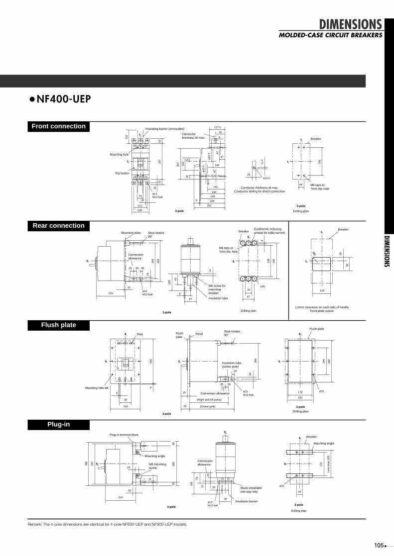
105
•NF400-UEP
Insulating barrier (removable)
Conductorthickness t8 max.
Conductor thickness t8 max.Conductor drilling for direct connection
M6 taps or7mm dia. hole
Breaker
3-pole
3-pole
Mounting hole
Trip button
ø14M12 bolt
16
4329
7
102
39
257
ø12
.5
ø12
.5
11.5
234
ø7
ø7
31
110
43
51
28
112
140
252
204
200
194
141
144
25
47
8
78
127.5
5
ø10.5
44
Drilling plan
Mounting plate Stud rotates90°
M6 screw formountingbreaker
M6 taps or7mm dia. hole
Exothermic reducinggroove for eddy currentBreaker
Breaker
R6
Drilling plan1.0mm clearance on each side of handle
Front-plate cutout
Insulation tube
3-pole
Connectionallowance
210ø13M12 bolt
10
25
8
8787
11844ø35
20 20
26
265
305
128
234
26
92
265
8
83
14
Stud
Mounting hole ø9
8 15
(Right and left poles)
Connection allowance
Insulation tube(center pole)
Stud rotates90°
Flush plate
Flushplate
Panel
ø13M12 bolt
(Center pole)64
25 20
20
172
192
ø10
87
216
533
0
26
265
194
308
3-poleDrilling plan
3-pole
218
1828
87
44
ø10
ø13M12 bolt
24
320
297
3528
265
160
79
175
Less
than
203
15
24
8
Plug-in terminal block
Mounting angle
M8 mountingscrew
Connectionallowance
Breaker
Mounting angle
Studs installableone-way only
Insulation barrier
3-poleDrilling plan
3-pole
Front connection
Rear connection
Flush plate
Plug-in
Remark: The 4-pole dimensions are identical for 4-pole NF630-UEP and NF800-UEP models.
DIMENSIONS
DIMENSIONSMOLDED-CASE CIRCUIT BREAKERS
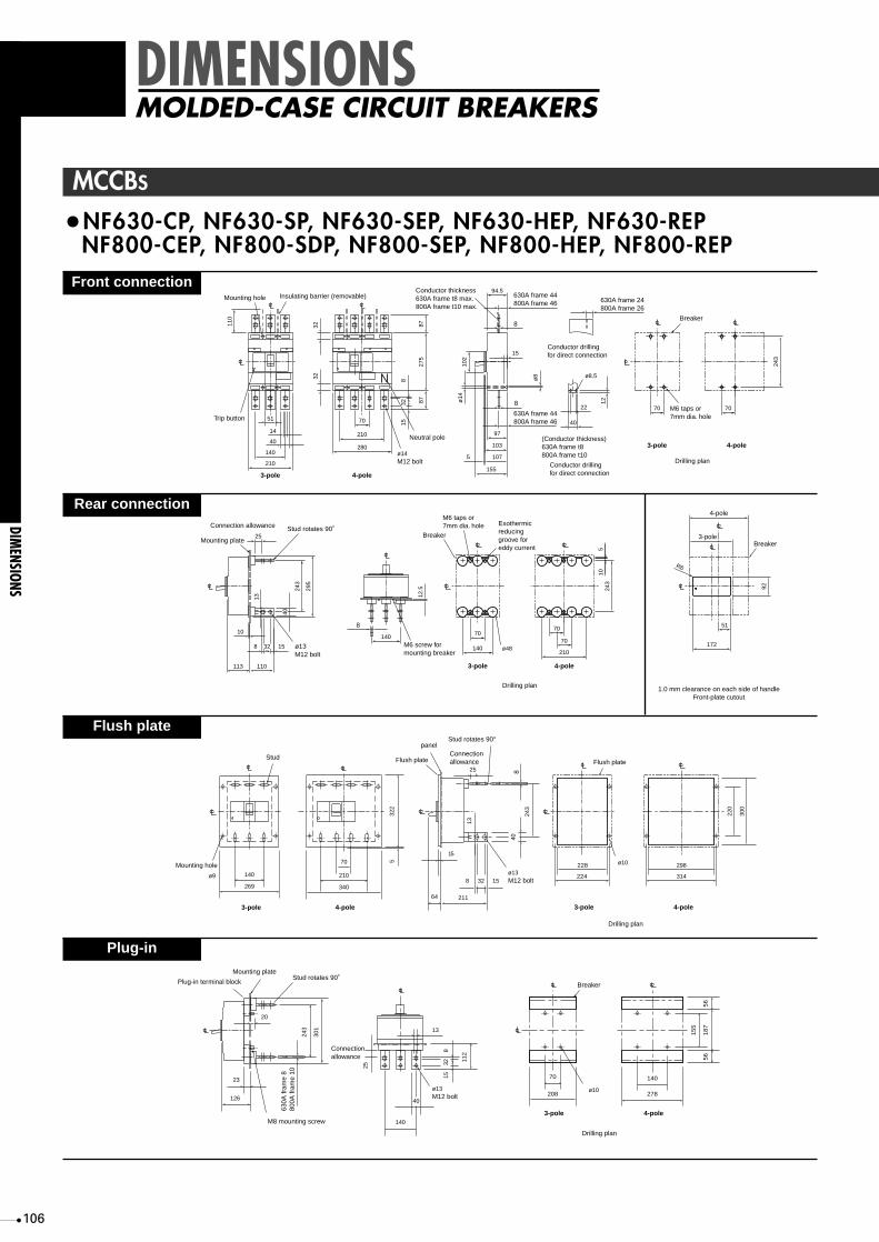
106
140
210
70
210
280
Trip button
Mounting hole Insulating barrier (removable)
3-pole 4-pole
110
14
40
51
32 815
32
275
87
97
103
107
87
32
ø14M12 bolt
Neutral pole
94.5630A frame 44800A frame 46 630A frame 24
800A frame 26
Conductor thickness630A frame t8 max.800A frame t10 max.
8
8
630A frame 44800A frame 46
102
15
22
40
ø8.5
5ø
14
ø8
155
12
(Conductor thickness)630A frame t8800A frame t10
Conductor drilling for direct connection
Conductor drilling for direct connection
Breaker
M6 taps or7mm dia. hole
3-pole 4-pole
Drilling plan
70 70
243
243
295
243
Mounting plate
Connection allowance
ø13M12 bolt
Stud rotates 90˚
3-pole 4-pole
Drilling plan
Exothermicreducinggroove foreddy current
M6 taps or7mm dia. hole
Breaker
ø48
70
140
40
25
13
8 15
113 110
140
32
10
M6 screw formounting breaker
12.5
70
70
210
105
172
51
92
4-pole
3-poleBreaker
1.0 mm clearance on each side of handleFront-plate cutout
R6
8
140
269
3-pole
Stud
Mounting hole
4-pole
300
220
70
210
340
322
5
228
224
298
314
Flush plate
3-pole 4-pole
Drilling plan
64
15
8 32 15
243
13
40
25
211
ø13
ø10
M12 bolt
Connectionallowance
Stud rotates 90°
8
Flush plate
panel
ø9
208
70
ø10ø13M12 bolt
M8 mounting screw3-pole
Breaker
278
140
15
5
56
56
18
7
4-pole
Drilling plan
13
40
140
Connectionallowance
630A
fram
e 8
800A
fram
e 10
3225
815
112
243
Mounting plate
Plug-in terminal blockStud rotates 90˚
20
301
126
23
•NF630-CP, NF630-SP, NF630-SEP, NF630-HEP, NF630-REPNF800-CEP, NF800-SDP, NF800-SEP, NF800-HEP, NF800-REP
Front connection
Rear connection
Flush plate
Plug-in
DIMENSIONS
DIMENSIONS
MOLDED-CASE CIRCUIT BREAKERS
MCCBS

107
•NF630-UEP, NF800-UEP, NF400-UEP (4-pole)
140
210
70
210
280
Trip button
Mounting holeInsulating barrier (removable)
3-pole 4-pole
110
1440
51
815
322
87
194
200
204
87
32
ø14M12 bolt
Neutral pole
143
97
64
630A frame
800A frame
630A frame 77.5 (ON side)800A frame 44 (ON side)121.5 (OFF side)
Conductor thickness630A frame t8800A frame t12
8
8630A frame 141800A frame 143
102
275
15
112
22
40
ø8.5
5
ø14
ø7
ø7
ø14
252
12
Conductor thickness630A frame t8 max.800A frame t10 max.Conductor drilling for direct connection
Conductor drilling fordirect connection
Breaker
M6 taps or7mm dia. hole
3-pole
4-pole
Drilling plan
70 70
290
210
70
35
280
4-pole
16
322
48
48
110
ø14M12 bolt
Neutral pole
(NF400-UEP)
27.5
194
141
200
204
143
97
6.5
6.5
Conductorthicknesst8 max.
Insulating barrier(removable)
Mountinghole
Tripbutton
102
275
15
112
5
ø14
ø7
ø7
ø14
252
27.5
290
290
342
Mounting plate
Con-nectionallowance
ø13M12 bolt
Stud rotates 90˚
3-pole 4-pole4-pole
Drilling plan(NF400-UEP)
Exothermicreducinggroove foreddy current
M6 taps or7mm dia. hole
Breaker
ø48
70
140
40
25
13
8
210 110
140
32
10 630A frame 8800A frame 10
M6 screw formounting breaker
12.5
70
70
210
105
172
51
92
22.5
4-pole
3-poleBreaker
1.0 mm clearance on each side of handleFront-plate cutout
R6
15
290
342
Mounting plate
Con-nectionallowance
ø13M12 bolt
Stud rotates 90˚25
26
210 83
10
20
347
155
140
Flush plateAngle-useattachment Mounting angle
312
M8 taps or10mm dia. hole
Drilling plan
Less
than
100
Less
than
100
70
239
3-pole4-pole 4-pole
140
283
3-pole
Stud
4-pole
70
210
353
370
5
64
15
8
8
10
102
15
290
13
40
25
206
ø13M12 bolt
Connectionallowance
Stud rotates 90°
Angle-useattachment
Mounting angle
630A
fram
e 8
800A
fram
e 10
Flush plate
Panel
32
64
158
10
75
20
290
26
25
206
ø13M12 bolt
Connectionallowance
(NF400-UEP)
Stud rotates 90°
Angle-useattachment
Mounting angle
Flushplate
panel
M8 mounting screw
M8 mounting screw
8
Plug-in terminal block Stud rotates 90˚
20 290
322
348
25
223
23
(A)
Fix plate
Mounting angle
Mounting angle
(A)Mounting angle
(B)
ø13M12 bolt
13
40
140
190
Connectionallowance
3225
815
112
172
202
172
(B)Mounting angle
Mounting angle (A)70
ø10
ø10
3-pole
Breaker
Drilling plan
Top view Base view
Less
than
234
190
Front connection
Rear connection
Flush plate
Plug-in (except NF800-UEP)
DIMENSIONS
DIMENSIONSMOLDED-CASE CIRCUIT BREAKERS

108
DIMENSIONS
DIMENSIONS
MOLDED-CASE CIRCUIT BREAKERS
•NF1000-SS, NF1250-SS
Mtg hole
Bolt M12 50Insulating barrier
(removable)
Ext.handle (removable)
3-pole 4-pole
110
832 80
15
13
43140210
210
70
280ø13M12 bolt
Neutral pole
ø9.
5
375
ø17
.5
18.5
280190
14017
15 44
4015
70 70
133.5
406
346
Breaker
4-pole3-pole
Drilling plan
M8 taps orø10
Conductor thickness 2 t8 max.
Mtg plate
Connectionallowance
Stud can berotated 90°
M10 terminal block mtg screw
M12✕ 45 bolt
Insulatingbarrier
1210
526
9
208 134
140
158
32 104
68
25.5
225
70204
140
136
100.
513
628
.5
269
28.5
274
30
4-pole
Drilling plan
3-pole
Conductorthickness2✕ t6 max.
ø12ø13
Plug-in terminalblock
43
13
Breaker
Front connection
Stud
Connectionallowance
Stud can berotated 90°
M12✕ 45 bolt
Insulating cover (removable)
14012
210
53
70
454
5
270 340 235
230 300244 314
220
426
328
22
13
45
273
109
1515.5
ø9 mtg hole
Drilling plan4-pole3-pole4-pole3-pole
Conductorthickness2✕ t6 max.
Flush plate Flush platePanel
ø13 ø10
Flush plate
Plug-in
Mtg plate
M12 bolt
Connectionallowance
mtg screwStud can berotated 90°
M8 breaker
Insulating cover (removable)140
140 230
8686
97
35.5
39.5
81.5
269
300
70 70
80
1mm clearance on each sideof handle
R11.5
97
8
13
273
109
15
12
22
18
32
ø13
Breaker
Breaker
4-pole
Drilling-plan Front-plate cutout4-pole3-pole
3-pole
M8 screw or ø10
45
Conductorthickness2✕ t6 max.
Rear connection
MCCBS
Insulating barrier
417376
190.5
464
232
257
514
387 25
7
97 464
232
257
1210
5
269
3-pole Drilling plan
3-pole
ø14
ø13
ø14 mtg hole
Liftins hole ø22
Breakercenter
Insertion anddrawout lever
30
896(drawout position)
911.5
13 1532
8
269(disconnected position)216(connected position)
Aux. circuit terminal
1026(drawout position)
409(disconnected position)
356(connected position)
43140
376
320(min)Stud attachable in this direction only
Mounting angle
Drawout
Notes : 1. Insulating barriers cannot be used when studs are horizontal. (Plug-in……Stud direction indicated is horizontal.)2. For 4-pole breakers, all horizontal dimensions are increased by 70mm. For drawout types, insulating barriers can
be supplied between the studs of different poles (optional).

109
DIMENSIONS
DIMENSIONSMOLDED-CASE CIRCUIT BREAKERS
•NF1000-SSD, NF1250-SSD
Mtg holeBolt M12 50
Insulating barrier(removable)
Ext. handle (removable)
3-pole 4-pole
110
832 80
15
13
140
210210
70
280
ø13M12 bolt
ø9.
5
375
ø17
.5
18.5
280190
14017
15 44
4015
70 70
133.5
406
346
Breaker
4-pole3-pole
Drilling plan
M8 taps orø10
Conductor thickness 2 t8 max.
43
Mtg plate
Bolt M12✕ 45
Connectionallowance
mtg screw
Stud can berotated 90°
M8 breaker
Insulating cover (removable)140
140 230
8686
20.5
97
35.5
375
187.
5
300
70 7080
1mm clearance oneach side of handle
R11.5
97
8
13
233
109
15
12
22
18
18
32
ø13
Breaker Breaker
4-pole
Drilling plan Front-plate cutout4-pole3-pole
3-pole
M8 taps or ø10
45
Conductorthickness2✕ t6 max.
Stud
Connectionallowance
Stud can berotated 90°
Bolt M12✕ 45
Insulating cover(removable)
140
12
21053
70
454
5
270 340 235
230 300
244 314
220
426
32
8
22
13
45
233
109
15
15.5
ø9 mtg hole
Drilling plan4-pole3-pole
4-pole3-pole
Conductorthickness2✕ t6 max.
Flush plate Flush platePanel
ø13ø10
Front connection
Rear connection
Flush plate
Notes : 1. The standard specifications of NF1000-SSD and NF1200-SSD are 2-pole.3-pole and 4-pole models for use with special DC voltages are also available.
2. 2-pole circuit breakers do not include mid-pole conductors of 3-pole circuit breakers.

110
DIMENSIONS
DIMENSIONS
MOLDED-CASE CIRCUIT BREAKERS
MCCBS
•NF1250-UR
Bolt M12 50
Insulating barrier (removable)
Ext. handle (removable)
3-pole 4-pole
ø13M12 bolt
Neutral pole
375
284194
15
346
51
22.5
1544
144137.5
17
70 70
Breaker
4-pole3-pole
Drilling plan
M8 taps orø10
Conductor thickness 2 t8 max.
328
8040
6
106
566
13
43
80
15
13
43 70210310
140240
ø17
.5
ø9.
5
Mountinghole
Terminalblock
Mtg plate
Connectionallowance
Bolt M12 45
Insulating cover (removable)
1mm clearance on each sideof handle
ø13
ø17
.5
ø9.
5 BreakerBreaker
4-pole
Drilling plan Front-plate cutout
4-pole3-pole
3-pole
M8 taps orø10
M8 screw for mounting
Conductorthickness2 t6 max.
28419414417 185
32137.522.5 8
8112
140 260 330 8070 70
8686
39.5
35.5
81.5
269
15
Terminalblock
Standard stud attachablein this direction
88
22
18
13 4510
927
3
120
97
R11.5
Connectionallowance
Bolt M12 45
Insulating cover (removable)
ø9.
5
ø13
Drilling plan
4-pole3-pole
4-pole3-pole
M8 taps orø10
Conductorthickness 2 t6 max.Terminal
block
332 438
284194
22.5185
32 292
81.5
269
506
70398
70
15
22
8
81
88
21070 12
14012
100
(max
)16
0(m
in)
Standard stud attachablein this direction
534
5
Flushplate
Flush plate
Mtg angle
Stud
Panel
273
4510
912
13
15.5 142
Bolt M12✕ 45
ø9.
5
ø13
ø12
13
30
158
32 104
ø17
.5
Drilling plan3-pole352
262
212
137.5 68 134140
204
70
136
100.
513
628
.5
28.5
269
22.5
25.5
225
12
269
105
22.5
17
43
BreakerMtg plate
Connectionallowance
Insulating barrier
M10 screw for mounting
Conductorthickness2✕ t6 max.
Plug-in terminal block
Stud can berotated 90°
Front connection
Rear connection
Flush plate
Plug-in

111
DIMENSIONS
DIMENSIONSMOLDED-CASE CIRCUIT BREAKERS
•NF1600-SS
Mtg hole
M10 bolt 65
Insulating barrier (removable)
Ext. handle (removable)
ø11
ø17
.5
ø9.
5
Neutral pole
Breaker
Breaker
4-pole3-pole
4-pole
3-pole
4-pole3-pole Drilling plan
M8 taps orø10
Conductor thicknesst6 75 max.
1mm clearance on each sideof handle
Front-plate cutout
210 280
203263
364.5280190
140133.5
17
20
20 35
70 7080
97
49.5
18.5
304.5101.5
6038
38
(185
.5)
(185
.5)15
406
130
346
375
115
R11.5
Connectionallowance
Connectionallowance
Angle mtg hole Angle mtg hole
Mtg angle
Stud can be rotated 90°Stud Stud can be
rotated 90°3-pole 4-pole
ø11M10✕ 50 bolt
ø11M10✕ 50 bolt
Breaker
4-pole
Drilling plan
3-pole
Conductor thicknesst6✕ 75 max.
Conductor thicknesst6✕ 75 max.
M8 taps orø10
160
(min
)
212
273
3660 5418
20
318
106
106
603818
273
269
81.5
109
38
15
15
140 125
70
1515 38
70
109
20
38 38125 15
200140
100
(max
)
Mtg angle
Stud can berotated 90°
4-pole 4-pole3-pole 3-pole
ø11
M10✕ 50 bolt
4-pole3-pole
Drilling plan
M8tapsor ø10
Conductor thicknesst6✕ 75 max.
Flush plateStud
Flush plate
Panel
Same asrear-connected type
160
(min
)
14020
53332 13815.5 125
1520
53
70292
70398
50626
981
.5
13815.5
125
70210438
15
36
553
4
273
109
1854
273
109
3838
200
6038
20
100
(max
)
Front connection
Rear connection
Flush plate
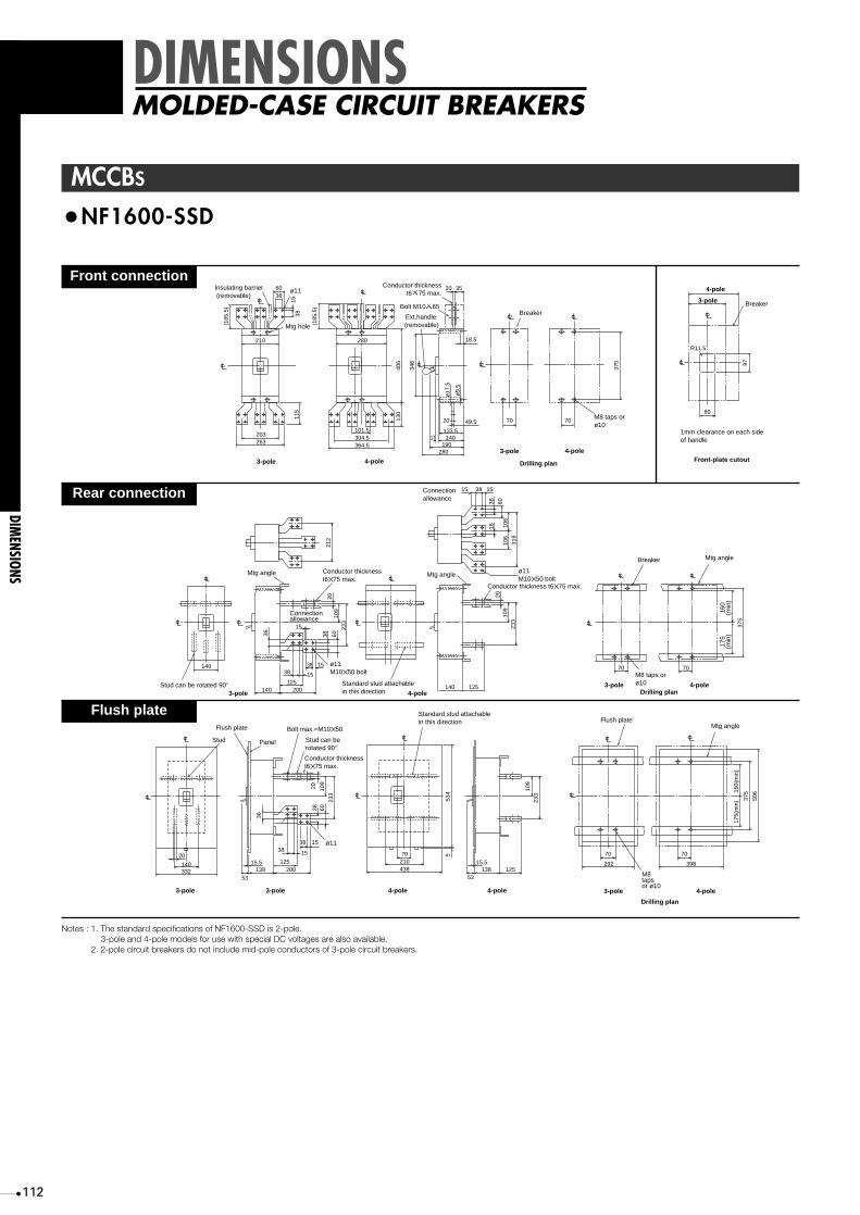
112
DIMENSIONS
DIMENSIONS
MOLDED-CASE CIRCUIT BREAKERS
MCCBS
•NF1600-SSD
Mtg hole
Bolt M10 65
Insulating barrier (removable)
Ext.handle (removable)
ø11
ø17
.5
ø9.
5
BreakerBreaker
4-pole3-pole
4-pole
4-pole
3-pole
3-pole
Drilling plan
M8 taps orø10
Conductor thicknesst6 75 max.
1mm clearance on each sideof handle
Front-plate cutout
6038
203263 364.5
18.5
280190
140133.5
20 70 70
80
R11.5
97
17
49.5
304.5101.5
20 35
210 280
(185
.5)
(185
.5)
1538
115
406
130
346
375
Connectionallowance
Connectionallowance
Standard stud attachablein this direction
Mtg angle
Mtg angleMtg angle
Stud can be rotated 90°3-pole 4-pole
ø11M10✕ 50 bolt
ø11M10✕ 50 bolt
Breaker
4-poleDrilling plan
3-pole
Conductor thicknesst6✕ 75 max.
Conductor thickness t6✕ 75 max.
M8 taps orø10
160
(min
)17
5(m
in)
140
140 200125
38 15
15
140
70 70
125
36 38 60
233
212
106
318
233
375
109
2010
6
1838 60
109
20
15
38
15 1538
Stud can berotated 90°
ø11
4-pole3-pole4-pole 4-pole3-pole3-pole
Drilling plan
M8tapsor ø10
Bolt max.=M10✕ 50
Conductor thicknesst6✕ 75 max.
Mtg angleFlush plate
Stud
Flush plate
Panel16
0(m
in)
175(
min
)
Standard stud attachablein this direction
140 15.5 125
38 15
138 200 438 13815.5
125
506
375
292 398
70 70
53
21070
33253
20
38
36
233
534
109
233
5
6010
9
2038
15
Front connection
Rear connection
Flush plate
Notes : 1. The standard specifications of NF1600-SSD is 2-pole.3-pole and 4-pole models for use with special DC voltages are also available.
2. 2-pole circuit breakers do not include mid-pole conductors of 3-pole circuit breakers.

113
ELCBS
•NV30-CS, MN30-CS
23.5
67.5
64 54 50
ø8.
5
14.5
12.5
76.5
96
Mtg. holeTest button
Leakageindicator button
M5 screw
Bus t max. =3
Bus drilling fordirect connection
Drilling planø
5
10
28
49
52
554
67
6
ø5.5
(max)
84
23.5
Breaker
M4 ✕ 0.7taps or ø5
Drilling plan
8476.5
23.5
Breaker
ø14
M4 ✕ 0.7 tapsor ø5
55
76.5
Mtg plat t max =3.2
Insulating tube
5
38.5
58.5
8
45 (
min
)
25 (
min
)
Breaker mtgM4 ✕ 0.7 screw
M6 screw
47
Front connection
Rear connection
Front-plate cutout
Breaker
R1
65
52
DIMENSIONS
DIMENSIONSEARTH-LEAKAGE CIRCUIT BREAKERS

114
ELCBS
•NV30-SP, NV50-CP, NV50-HP, NV60-CP, NV60-HP, MN50-CP MN50-SP
Trip button Test button
Leakageindicaton button
Sensitivity currentselector
Mounting hole
Insulation barrier(removable)
22
50
111
111
130
75
24
27
61
68
724
90
84 50
ø8.
5
ø4.
5
M5 ✕ 0.8 screw(M6 for NV60-CP, -SP, -HP)
Applicable wire size : 1.6 mm dia. to 22 mm2
Screw terminal
Drilling plan
6
ø5.5(6.5 mm-dia. for NV60-CP, -SP, or - HP)
(Conductor thickness t = 5 max.)
Conductor drilling for direct connection
12.5 max.25
Breaker
M4 ✕ 0.7 tapsor 5 mm dia. hole
27
111
8
min.
68 42
72
50
Mounting panel t = 3.2 max.
Insulation tube
M6 screw
M4 ✕ 0.7 screwfor breaker mounting
6
Drilling plan
ø1425
111
50M4 ✕ 0.7 tapsor 5 mm-dia. hole
Breaker
52
70
Breaker
1.0 mm clearance on eace sideof the handle frame.
Front-panel cutout
R1
9735
50
121
196
Mounting holeø6
Flush plate Panel
111
8
M6 screw
Flush plate
ø682 min.15 93
103
140
(Not
e 1)
66 o
r 60
Stud
11
15.55.5
83.5
111
180
83.5
3
89 30
21
Plug-in terminal block
Details of terminal
Mounting panel
M6 screw
M5 ✕ 0.8 screw Terminal boardto be fixed using terminalblock mounting nuts or bydirectly screwing in it.
Center line ofbreaker body
Conductor drilling cutoutfor direct connection
10
50
80
7
16.5 max.
ø6.582
25
Breaker (plug-in terminal block)
6 mm-dia. hole orM5 ✕ 0.8 taps
Cutout and drilling plan
54 8054
54
Front connection
Rear connection
Flush plate
Plug-in
DIMENSIONS
DIMENSIONS
EARTH-LEAKAGE CIRCUIT BREAKERS

115
30
Trip button Trip button
Mounting hole
Insulation barrier(removable)
22
60
90 90
120
134
155
50
Neutral pole
Leakageindicator button
Leakageindicator button
24
27
61
68
724
9010
2
50
ø8.
5
ø4.
5
8
M8 screw
ø8.5
(Conductor thickness t = 5 max.)
Conductor drilling for direct connection 3-pole
Drilling plan
4-pole
16.5 max.
30 30
Breaker
M4 ✕ 0.7taps or 5 mm-dia. hole
132
3-pole 4-pole
Solderless terminalfor wire size15~75A ø1.6~38mm2
80~100A 22~50mm2
Wire connection
Test buttonTestbutton
Sensitivity currentselector
Sensitivity currentselector
Operating timeselector(time-delay type)
Operating timeselector(time-delay type)
68 52
134
15
15
16
10272
15 ø8.5M8 bolt
Connectionallowance
Insulation tube
Mounting panelt = 3.2 max.
Stud rotatableby 90°
3-pole4-pole
5
60
90
M4 ✕ 0.7 screwfor breakermounting
Insulation tube
6
Breaker Breaker
ø1830
60
M4 ✕ 0.7 taps or5 mm-dia. hole
3-pole 4-pole
132
134
30
30
90
28
86
52
R1
3-pole
4-pole
1.0 mm clearance on each sideof the handle frame.
Front-panel cutout
60
152
3-pole
Terminal cover
Stud6mm-dia.mounting hole
4-pole
181
66
30
90
187
196
Insulation tube (provided forintermediate pole for 3-pole orfor intermediate and neutralpoles for 4-pole)
126
136
161
171
Flush plate
3-pole 4-pole
Cutout and drilling plan
ø6
(Intermediate pole for 3-pole andintermediate and neutral polesfor 4-pole)
(Right and left poles forboth 3- and 4-poles)
35
15 107.5
134
15
15
16
157.5
15
ø8.5M8 bolt
Connectionallowance
Stud rotatableby 90°
Flush plate panel
5
11
205.5
98 134
190
89 30
21
Plug-in terminal block
Details of terminal
Mounting panel
M8 screw
M5 ✕ 0.8 screw Terminal blockto be fixed using terminal boardmounting nuts or to be directlyscrewing it in.
Center lineof breaker body
Conductor drillingfor direct connection
12.5
60
95
3090
125
3-pole
4-pole
12
16.5 max.
ø8.5
3-pole 4-pole
97
30
127
60
Breaker (plug-in terminal block)
6 mm-dia. hole orM5 ✕ 0.8 taps
Cutout and drilling plan
54 9456
56
•NV100-CP, NV100-SP, NV100-HP, NV100-SEP, NV100-HEP, MN100-SP
Front connection
Rear connection
Flush plate
Plug-in
Remarks : NV100-CP, NV100-SP NV100-HP and MN100-SP are only available as 3-pole models.
DIMENSIONS
DIMENSIONSEARTH-LEAKAGE CIRCUIT BREAKERS

116
Trip button
Mounting hole
3-pole 4-pole
Insulation barrier(removable)
22
105105
140
35
144
165
100
100
70
Neutral pole
24
45
61
68
724
9210
2 50
ø8.
5
ø4.
5
Hex. socket headM8 bolt
23 max.
(Conductor thickness t = 7 max.)
Conductor drillingfor direct connection
ø8.5
10
M4 ✕ 0.7 taps or 5 mm-dia. hole
3-pole 4-pole
Drilling plan
Breaker
35 35
126
Sensitivity currentselector
Operating time selector(time-delay type)
Leakageindicatorbutton
Test button
Test buttonTripbutton
Sensitivity current selector
Operating time selector(time-delay type)
Leakageindicator button
Solderless terminalfor wire size
100~175A200~250A
14~95mm2
70~125mm2
Wire connection
68 71
144
22
15
20
10672
15ø9M8 bolt
Connectionallowance
Insulation tube
Mounting panelt = 3.2 max.
Stud rotatableby 90°
4-pole
3-pole
6
70
105
M4 ✕ 0.7 screwfor breakermounting
Insulation tube
8
Breaker
ø24
35
70M4 ✕ 0.7taps or5 mm-dia. hole
3-pole 4-pole
Drilling plan
126
144
35
35
105
Breaker
32.5
100
52
R1
3-pole
4-pole
1.0 mm clearance on each sideof the handle frame.Front-plate cutout
70
152
3-pole
Terminal cover
Stud 6 mm-dia.mounting hole
4-pole
35
105
187
196
Insulation tube (provided forintermediate pole for 3-pole or for intermediate and neutral poles for 4-pole)
(Intermediate pole for 3-pole andintermediate and neutral poles for 4-pole)
(Right and left poles for both 3- and 4-poles)
37
15 126
144
15
22
20
161
15ø9M8 bolt
Connectionallowance
Stud rotatableby 90°
Flush plate Panel
6
181
66
126
136
161
171
Flush plate
3-pole 4-pole
Cutout and drilling plan
ø6
14
200
18
3286
144
34.5
28
6
M6 screw for mountingterminal block
Plug-in terminal blockMounting panel
Con
nect
ing
allo
wan
ce
M8 bolt
Studs can be installed inthis direction only.
Center lineof breaker body
3-pole
Breaker (plug-in terminal block)
Cutout and drilling plan
4-pole
Insulation barrier
ø9
20
70
70
22
15
153
70
107
105
142
ø7
54 8058
.558
.5
Front connection
Rear connection
Flush plate
Plug-in
Remark: NV225-CP/SP/HP and MN225-SP are only available as 3-pole models.
ELCBS
•NV225-CP, NV225-SP, NV225-HP, NV225-SEP, NV225-HEP, MN225-SP
DIMENSIONS
DIMENSIONS
EARTH-LEAKAGE CIRCUIT BREAKERS
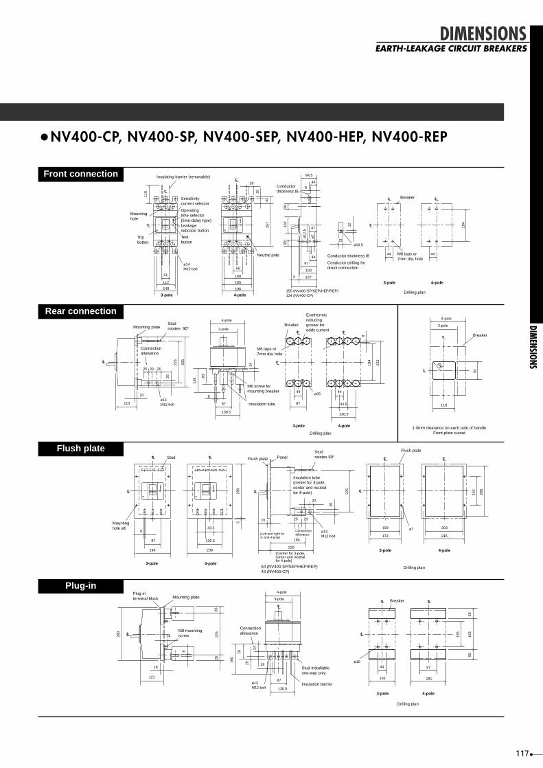
117
•NV400-CP, NV400-SP, NV400-SEP, NV400-HEP, NV400-REP
DIMENSIONS
DIMENSIONSEARTH-LEAKAGE CIRCUIT BREAKERS
Conductorthickness t8.
3-pole 4-pole
102
3939
ø12
.5
ø7
155 (NV400-SP/SEP/HEP/REP)134 (NV400-CP)
107
103
97
44
8
44
94.5
5
47
Conductor thickness t8
12
25ø10.5
M6 taps or7mm dia. hole
Breaker
44 44
194
Insulating barrier (removable)
Sensitivitycurrent selector
Operatingtime selector(time-delay type)Leakageindicator button
Testbutton
Mountinghole
Tripbutton
ø14M12 bolt
110 16
4325
7
51
112
140
Neutral pole
28
185
196
168
56
4-pole3-pole
Drilling plan
Conductor drilling fordirect connection
Mounting plateStudrotates 90°
Breaker
1.0mm clearance on each side of handleFront-plate cutout
R6
Connectionallowance
113
10ø13M12 bolt
25
118
92
20 20
26
225
265
M6 taps or7mm dia. hole
Exothermicreducinggroove foreddy current
Breaker
Drilling plan
87
44ø35
43.5
130.5
4-pole
4-pole
3-pole
3-pole
44
194
225
8
M6 screw formounting breaker
Insulation tube
8
4-pole
3-pole
87
130.5
128 83
14
Stud
Mountinghole ø6
8
87
194
43.5
130.5
238
529
0
Flush plate
172
159 ø7
3-pole
15
(Left and right for3- and 4-pole)
(Center for 3-pole,center and neutralfor 4-pole)
Connectionallowance
Insulation tube(center for 3-pole,center and neutral for 4-pole)
Studrotates 90°Flush plate Panel
ø13M12 bolt
25
184
229
20
20
26
225
3-pole 4-pole64 (NV400-SP/SEP/HEP/REP)43 (NV400-CP)
216
203
152
268
4-pole
Drilling plan
Drilling plan
28
87
130.5
136
44 ø10
4-pole
3-pole
ø13M12 bolt
160
79
15
24
Connectionallowance
Stud installableone-way only
Insulation barrier
121
18
24280
3528
225
8
Plug-interminal block Mounting plate
Breaker
M8 mountingscrew
3-pole 4-pole
181
87
135
163
5555
Front connection
Rear connection
Flush plate
Plug-in
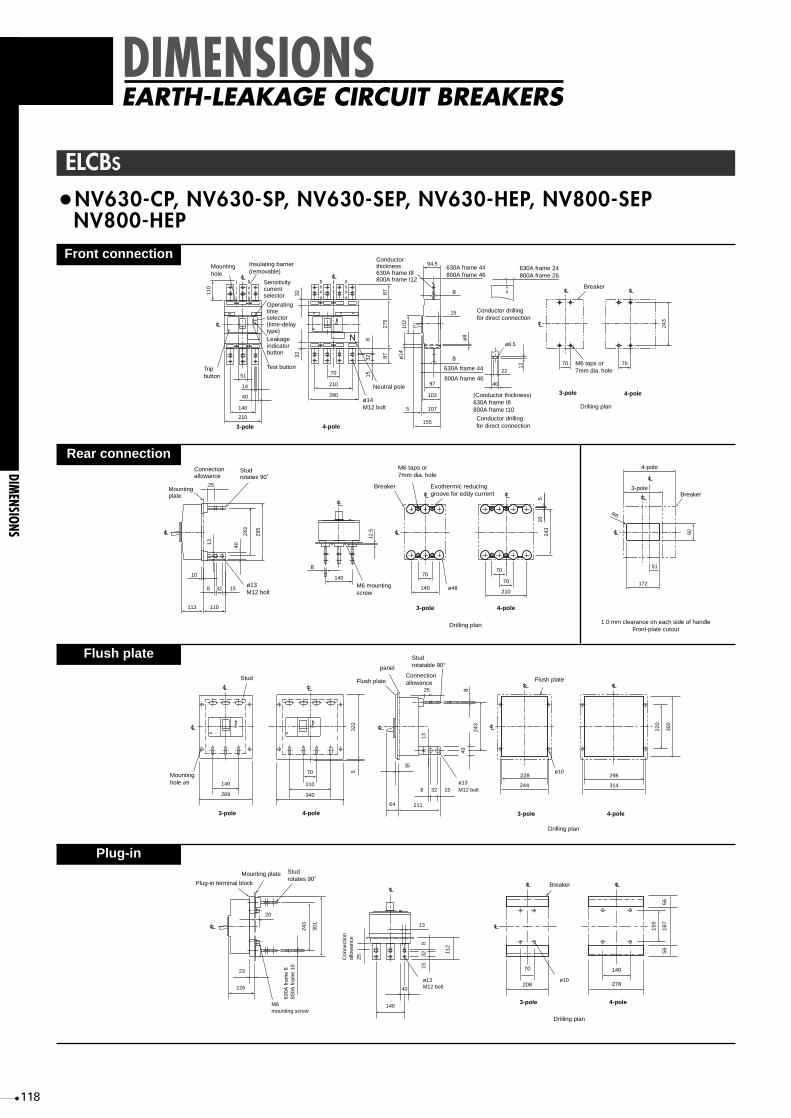
118
•NV630-CP, NV630-SP, NV630-SEP, NV630-HEP, NV800-SEP NV800-HEP
140
210
70
210
280
Trip button
Mounting hole
Insulating barrier (removable)
3-pole 4-pole
110
14
40
51
32
815
32
275
8797
103
107
87
32
ø14M12 bolt
Neutral pole
94.5630A frame 44800A frame 46
630A frame 24800A frame 26
Conductorthickness630A frame t8800A frame t12
8
8
630A frame 44
102
15
22
40
ø8.5
5
ø14
ø8
155
12
(Conductor thickness)630A frame t8800A frame t10
Conductor drilling for direct connection
Conductor drilling for direct connection
Breaker
M6 taps or7mm dia. hole
3-pole 4-pole
Drilling plan
70 70
243
800A frame 46
Test button
Leakageindicatorbutton
selector(time-delaytype)
Operatingtime
Sensitivitycurrentselector
295
243
Mounting plate
Connection allowance
ø13M12 bolt
Stud rotates 90˚
40
25
13
8 15
113 110
140
32
108
M6 mounting screw
12.5
243
3-pole 4-pole
Drilling plan
Exothermic reducinggroove for eddy current
M6 taps or7mm dia. hole
Breaker
ø48
70
140
70
70
210
105
172
51
92
4-pole
3-poleBreaker
1.0 mm clearance on each side of handleFront-plate cutout
R6
140
269
3-pole
Stud
Mounting hole ø9
4-pole
300
220
70
210
340
322
5
228
244
298
314
Flush plate
3-pole 4-pole
Drilling plan
64
15
8 32 15
243
13
40
25
211
ø13
ø10
M12 bolt
Connectionallowance
Stud rotatable 90°
8
Flush plate
panel
208
70
ø10ø13M12 bolt
M8mounting screw
3-pole
Breaker
278
140
15
5
56
56
18
7
4-pole
Drilling plan
13
40
140
Con
nect
ion
allo
wan
ce
630A
fram
e 8
800A
fram
e 10
3225
815
112
243
Mounting plate
Plug-in terminal block
Studrotates 90˚
20
301
126
23
Front connection
Rear connection
Flush plate
Plug-in
ELCBS
DIMENSIONS
DIMENSIONS
EARTH-LEAKAGE CIRCUIT BREAKERS

119
•BH •BH-S
•BH-P
•BH-D6
•BH-PS
MCBS
25
22
1-pole
50
25
Types BH
75
50
95 9557 113
100
73
Breakercenter
Mtg hole ø4.5
Mtg bracketM5 x 0.8 screw
(line side & load side)
32
57.5
63.5
77.547
2-pole
47
3-pole 13.5
5.5
6
12
ø5.5
Bus t max. =4
Bus drilling
Note: Two mounting brackets are used for single-pole breakers. and four for two-pole and three-pole breakers.
25 50
25 25
20.5
1-pole
75
25
71.5
7457.5
7.5
M5 x 0.8screw
Mtg slot
Plug-in terminal(line side)
60.5
65.5
7945.5
2-pole
70.5
3-pole 14
4.5
70 maximum
17 44 6
InsulationBarrier(Option)
8744
.5
45 92
18 36 54 7254
1818 36
M5 screwNeutral Pole
1-pole 2-pole 3-pole 4-pole
Solderless terminal
Mtg bracket
25
1-pole
50
25
95 9557 113
100
73
Mtg holeø4.5
M5 x 0.8 screw(line side & load side)
32
57.5
63.5
76
2-pole 3-pole
5.5
6
12
ø5.5
Bus t max. =4
Bus drilling
Note: Two mounting brackets are used for single-pole breakers. and four for two-pole and three-pole breakers.
75
50
13.5
25
1-pole 2-pole 3-pole
71.5
81.5
57.5
7.5
M5 x 0.8screw
Plug-in terminal(line side)
Mtg slot
60.5
65.5
79
4.5
50
25
75
25 25
22 47 72
14
70 maximum
17 44 6
8744
.5
45 92
18 36 54 7254
1818 36
M5 screwNeutral Pole
1-pole 2-pole 3-pole 4-pole
InsulationBarrier(Option)
Solderless terminal
70 maximum
17 44 6
85
42.5
45
18
36
54
18
72
M5 screw Test button Neutral poleResidual indicator
2-pole 4-pole
Solderless terminal
•BV-D •KB-D
DIMENSIONS
DIMENSIONSMINIATURE CIRCUIT BREAKERS

120
seireSA
frame
rebmunledoM noitazidradnatsnoisnemidlanretxE
remroF weN VN=FN S=CSame module
for 4-polemm86dradnatS
thgiehrofezislenapemaS
VN/FN
C-FN
Molded-casecircuitbreakers
Earthleakagecircuitbreakers
SC-06/05FN PC-06/05FN ● ● — ● ●
SC-001FN PC-001FN ● ● — ● ●
SC-052FN PC-052FN ● ● —
—
—
● ●
S-FN
HS-06/05FN PH-06/05FN ● ● ● ● ●
SS-001FN PS-001FN ● ● ● ● ●
HS-001FN PH-001FN ● ● ● ● ●
PEH/PES-001FN ● ● ● ● ●
SS-052FN,SS-061FN PS-052FN,PS-061FN ● ● ● ● ●
HS-052FN,HS-061FN PH-052FN,PH-061FN ● ● ● ● ●
ES-052FN PEH/PES-052FN ● ● ● ● ●
C-VN
FC-06/05VN PC-06/05VN ● ● — ● ●
FC-001VN PC-001VN ● ● — ● ●
FC-522VN PC-522VN ● ● — ● ●
S-VN
FS-06/05/03VN PS-06/05/03VN ● ● — ● ●
PH-06/05VN ● ● — ● ●
FS-001VN PS-001VN ● ● — ● ●
BH-001VN PH-001VN ● ● — ● ●
)P4SS-001VN( PEH/PES-001VN ● ● ● ● ●
FS-522VN PS-522VN ● ● — ● ●
BS-522VN PH-522VN ● ● — ● ●
)P4SS-052VN( PEH/PES-522VN ● ● ● ● ●
BM
SC-05BMSS-05/03BM PC-05BMPS-05/03BM ● ● — ● ●
SS-001BM PS-001BM ● ● — ● ●
SS-522BM PS-522BM ● ● — ● ●
NM
FS/FC-05NM PS/PC-05NM ● ● — ● ●
FS-001NM PS-001NM ● ● — ● ●
FS-522NM PS-522NM ● ● — ● ●
● sledomwenrofmetidevorpmI:
COMPARISONCOMPATIBILITY BETWEEN NEW AND FORMER MODELS
30~250AF
COMPARISON
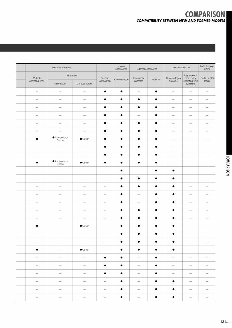
121
COMPARISONCOMPATIBILITY BETWEEN NEW AND FORMER MODELS
srekaerbcinortcelElanretnI
seirossecca seirosseccalanretxEstiucriccinortcelE
egakael-htraEmrala
elpitluM.rahcgnitarepo
mrala-erPesreveR
noitcennocepyt-ettessaC
yllacirtcelEdetarepo
S-LH/LHsegatloveerhT
elbaliava
/deeps-hgiHyaled-emiT
emitgnitarepognihctiws
ACEaivsdaoLsdael
tuptuoRSS tuptuotcatnoC
— — — ● ● — ● — — —
— — — ● ● ● ● — — —
— — — ● ● ● ● — — —
— — — ● ● — ● — — —
— — — ● ● ● ● — — —
— — — ● ● ● ● — — —
●● /dradnatssA
noitpO ● noitpO ● ● ● ● — — —
— — — ● ● ● ● — — —
— — — ● ● ● ● — — —
●● /dradnatssA
noitpO ● noitpO ● ● ● ● — — —
— — — — ● — ● ● — —
— — — — ● ● ● ● — —
— — — — ● ● ● ● — —
— — — — ● — ● ● — —
— — — — ● — ● ● — —
— — — — ● ● ● ● — —
— — — — ● ● ● ● — —
● — ● noitpO — ● ● ● ● — —
— — — — ● ● ● ● — —
— — — — ● ● ● ● — —
● — ● noitpO — ● ● ● ● — —
— — — ● ● — ● — — —
— — — ● ● — ● — — —
— — — ● ● — ● — — —
— — — — ● — ● ● — —
— — — — ● — ● ● — —
— — — — ● — ● ● — —
COMPARISON

seireSA
emarf
rebmunledoMnoisnemidlanretxE
noitazidradnats epyt-ettessaCseirossecca
elpitluM.rahcgnitarepo
mrala-erP
remroF weN VN=FNeludomemaS
elop-4roftuptuoRSS tuptuotcatnoC
-dedloMesac
tiucricsrekaerb
C-FN
004 SC-004FN PC-004FN ● — ● — — —
036 SC-036FN PC-036FN ● — ● — — —
008 SC-008FN PEC-008FN ● — ● ● ● ●
S-FN
004
SS-004FN PS-004FN ● ● ● — — —
ES-004FN PES-004FN ● ● ● ● ● ●
— PEH-004FN ● ● ● ● ● ●
— PER-004FN ● — ● ● ● ●
036
SS-036FN PS-036FN ● ● ● — — —
ES-036FN PES-036FN ● ● ● ● ● ●
— PEH-036FN ● ● ● ● ● ●
— PER-036FN ● — ● ● ● ●
008
SS-008FN PES-008FN ● ● ● ● ● ●
DSS-008FN PDS-008FN — ● ● — — —
— PEH-008FN ● ● ● ● ● ●
— PER-008FN ● — ● ● ● ●
U-FN
004 RU-004FN PEU-004FN — — ● ● ● ●
036 RU-036FN PEU-036FN — ● ● ● ● ●
008 RU-008FN PEU-008FN — ● ● ● ● ●
htraEegakael
tiucricsrekaerb
C-VN004 FC-004VN PC-004VN ● — ● — — —
036 AC-036VN PC-036VN ● — ● — — —
S-VN
004
FS-004VN PS-004VN ● — ● — — —
SS-004VN PES-004VN ● — ● ● ● ●
P4BS-004VN P4PES-004VN ● ● ● ● ● ●
— PEH-004VN ● — ● ● ● ●
— PER-004VN ● — ● ● ● ●
036
P3BS-006VN PS-06VN ● — ● — — —
— P3
3
3
3
3 PES-06VN ● — ● ● ● ●
P4BS-006VN P4PES-06VN ● ● ● ● ● ●
— PEH-06VN ● — ● ● ● ●
008BS-008VN PES-008VN ● — ● ● ● ●
— PEH-008VN ● — ● ● ● ●
● sledomwenrofmetidevorpmI
122
COMPARISONCOMPATIBILITY BETWEEN NEW AND FORMER MODELS
400~800AF
COMPARISON

123
30~800AF
• Former (example: NF100-SS) • New (example: NF100-SP) • Former (example: NV100-SF) • New (example: NV100-SP)
• Bar stud (new 100AF)
•Appearance
•Front panel cutouts (partial list of main NF/NV models)
Includes a trip button within the panelcutout. New model indicates IEC60947-2Icu/Ics on the nameplate.
Includes a dial selector switch.Sensitivity current is selectable using aJIS based 4.5x50 screwdriver. Newmodel also includes a trip button.
FN VN
remroFSC-052FN~SC-05FNSS-052FN~SS-03FN
HS-052FN,HS-001FN,RH-05FN
SC-008FN~SC-004FNSS-008FN~SS-004FN
-008FN~PC-004FN-008FN~PS-004FN
FC-522VN~FC-05VNFS-522VN~FS-03VN FC-004VN
PC-004VNweNPC-052FN~PC-05FNPS-052FN~PS-03FN
PH-052FN,PH-001FN,PRHPECPES-05FN
PC-522VN~PC-05VNPS-522VN~PS-03VN
ytilibitapmoC ehtmorfecnatsidehT.lenaptnorfehtnodesueboslanacsezistuotucremroF.)thgirtaerugifees(remrofehtmorfsreffidlenaptnorfehtotesabrekaerb
A052wenehT.derussasiytilibitapmoCmm81sithgiehrekaerbs'emarf)A522(
.remrofehtnahtrewo
•Connection parts (partial list of 3-pole C series models or equivalent)
• Rear studs for 100AF andNF50-HRP have changedfrom screw studs to bar studs(new).
• Screw stud (former 100AF)
•Dimensions (400AF 4-pole models) •Front panel cutouts (some as previous NF)
53(Note 1)
72
9250
107
4-pole
3-pole
R2
Breaker
24
52
4-pole
3-pole
2-pole
R1
The cutout size is equal to breaker's windowframe plus 1mm clearance.
• Both the overall module dimensions and bar terminaldimensions are altered greatly.
emantcudorP)TS-B(dutsraeR )PF(etalphsulF )MP(ni-gulP
remroF weN ytilibitapmoC remroF weN ytibitapmoC remroF weN ytilibitapmoC
emarF)A(
06/05/03 3SS50-TS)dutswercs(
3PS50-TS)dutswercs(
neveelbitapmoCledomhguohtreffidsrebmun
3SS50-PF 3PS50-PF
elbitapmocnI
3SS50-MP 3PS50MP
elbitapmocnI001 3SS1-TS)dutswercs(
3PS1-TS)dutsrab(
elbitapmocnI
3SS1-PF)dutswercs(
3PS1-PF)dutsrab( 3SS1-MP 3PS1-MP
052 3SS2-TS)dutsrab(
3PS2-TS)dutsrab(
3SS2-PF)dutsrab(
3PS2-PF)dutsrab(
3SS2-MP3PS2-MP
004 3SS4-TS 3PS4-TS ● 3SS4-PF 3PS4-PF ✕ 3SS4-MP 3PS4-MP ●
036 — 3PS6-TS — 3SS6-PF 3PS6-PF ✕ 3SS6-MP 3PS6-MP ●
008 — 3PS6-TS — 3SS6-PF 3PS6-PF ✕ 3SS8-MP 3PS8-MP ●
COMPARISON
COMPARISONOTHER CHANGES
70
35
280
70 70
275
48
16
56
28
56 56
275
43
16
185
196

124
COMPARISONOTHER CHANGES
Internal accessories
•Lead-wire terminal blocks (Front/rear connection and plug-in types only; excludes P-LT types)
epyT remroF weN
)TL(kcolblanimreteriw-daeL ● —
)TLS(kcolblanimreteriw-daeL ● ●
• All new models use a vertical lead-wire terminal block (SLT).
• Lead-wire terminal block (LT) • Vertical lead-wire terminal block (SLT)
•Test lead (TBL) and Test button module (TBM) for ELCBs
remroF weN
LBT ● ●
MBT — ●
The TBM has the following features:• Standard with SLT.• Uses a voltage-application system and offers same control sequence
to that of SHT..• Permits TBM parallel connection.• Offers enhanced safety becuase it is isolated from the main circuit.
remroF )tuptuoRSS(weN )tuptuotcatnoc(weN
srekaerbtiucricesac-dedloMsrekaerbmrala-erP
)noitacificepslaiceps(yaleretats-dilossahsBCCMcinortceledradnatsehT
.dradnatssamrala-erptuptuo)RSS(mrala-erpahtiwledomasaelbaliavayllanoitpO
.sBCCMcinortceledradnatsehtnieludom
srekaerbtiucricegakaelhtraE — —mrala-erpahtiwledomasaelbaliavayllanoitpO
.sBCLEcinortceledradnatsehtnieludom
•Pre-Alarms
COMPARISON

125
COMPARISONOTHER CHANGES
External accessories
•Operating handles (F, S, SS types) (Main NF/NV models shown) (30-250AF)
•Enclosures (Shown for 3-pole C series models or equivalent)
remroF weNytilibitapmoC
epytrekaerB rebmunstraP epytrekaerB rebmunstraP
HS/SC-05FN,SS-03FNFS-03VN,HS/SC-06FN
FS/FC-06VN,FS/FC-05VN
FS30S,FS30FFS241
PH/PC-05FN,PS-03FNPS-03VN,PH/PC-06FN
PS/PC-06VN,PS/PC-05VN
PS50S,PS50FPS50SS
● dnasnoisnemidlanretxecisabehT.degnahcnuerasezisgnillird/tuotuc
● thgiehtnereffidaevahsledomwenemoSderapmoctnorflenapehtotesabrekaerbmorf
.sledomsuoiverpot
● ebtonnacseldnahgnitareporemrofehT.srekaerbwenehtotdehcatta
SS/SC-001FN 01F01SSS141
PH/PS/PC-001FN,PRH-05FNPS/PC-001VN
PS1S,PS1FPS1SS
HS-001FN,RH-05FN 11F
SS/SC-052FN,SS-061FN )FN(FS02F02SSS24 PH/PS-061FN
PH/PS/PC-052FNPS/PC-522VN
PS2S,PS2FPS2SSHS-052FN,HS-061FN 12F
FS/FC-522VN)VN(02S,)VN(FS02F
)VN(SS24
• The new F and S-type handles show the tripping of a breaker even in ON-lock status. (Applies only when a padlock is used.)
emantcudorP)S(epytdesolC )I(epytfoorptsuD )W(epytfoorpretaW
remroF weN ytilibitapmoC remroF weN ytilibitapmoC remroF weN ytilibitapmoC
FA
05 • 06FN SS50-SFN
PS50-SFN erasledomBCLEneve,elbitapmoc
traphguoht.reffidsrebmun
sledomBCCM.elbitapmocniera
FS50-IFN PS50-IFN
elbitapnocnI
SS50-WFN PS50-WFN
elbitapmocnI
VN FS50-SVN
001FN SS1-SFN
PS1-SFN SS1-IFN PS1-IFN SS1-WFN PS1-WFNVN FS1-SVN
052FN —
PS2-SFN elbitapmocnISS2-IFN
PS2-IFNSS2-WFN
PS2-WFNVN FS2-SVN FS2-IVN FS2-WVN
•Terminal covers (Shown for 3-pole C series models or equivalent)
•Motor operation devices
emantcudorP)L-CT(revoclanimretegraL )S-CT(revoclanimretllamS )CTT(revoclanimrettnerapsnarT )CTB(revoclanimretraeR
remroF weN remroF weN remroF weN remroF weN
FA
05 • 06 3SS50-LCT 3PS50-LCT 3SS50-SCT 3PS50-SCT 3SS50-CTT 3PS50-CTT 3SS50-CTB 3PS50-CTB
001 3SS1-LCT 3PS1-LCT 3SS1-SCT 3PS1-SCT 3SS1-CTT 3PS1-CTT 3SS1-CTB 3PS1-CTB
052 3SS2-LCT 3PS2-LCT 3PS2-SCT 3PS2-SCT 3SS2-CTT 3PS2-CTT 3SS2-CTB 3PS2-CTB
remroF weN
epytrekaerB A epytrekaerB A
SS/SC-001FNFS/FC-001VN
051 PRH-05FNPH/PS/PC-001FNPH/PS/PC-001VN
451RH-05FNHS-001FN
861
SS/SC-052FNFS/FC-522VN
071PH/PS/PC-052FNPH/PS/PC-522VN
451
HS-052FN 781
• 50AF and 60AF models are compatible, even though part numbers differ. (Note, however, that using an earlier terminal cover on a new breaker will block the internal accessories' leads from exiting on the load side.) 100AF and 250AF models are incompatible.
A
• The new NF/NV C and S series breakers can accept electric operation devices.
• The electric operation device's performance and operation characteristics are unchanged.
• The external dimensions (shown for the main NF/NV models) are unchanged, except for height A in the figure.
• Front connectiontype
COMPARISON

126
COMPARISONOTHER CHANGES
External accessories
•Mechanical interlocks (MI) (Shown for surface mounting 2/3-pole C/S series or equivalent)
•Locks
FAremroF weN
rebmuntraP PdradnatS t rebmuntraP PdradnatS t
FN 3SS50-IM 49
3.2)dradnatS(
3PS50-IM 021deriuqertoN
ebotdeificeps
VN 3SS50VN-IM 021
FN 3SS1-IM 001
VN 3SS1VN-IM 021
052FN 3SS2-IM 511
VN 3SS2VN-IM 021
06,05,03)PRH-05FNgnidulcniton(
001)PRH-05FNgnidulcni(
• The new MIs have a different shape and install in a different position.• The new MIs can be locked with a padlock (25mm).
• All new handle locks can be installed by the customer. (Use a 25mm padlock for HL models or 35mm padlock for HL-S.)
• New handle locks differ in shape from the former models and are thus incompatible.
emantcudorP
)CL(revockcoL )LH(kcoleldnaH )S-LH(kcoleldnaH
remroF weN remroF weN remroF weN
FA
06,05,03)PRH-05FNgnidulcniton(
30CL
PS50-CL
saderedroeboTrekaerbehtnidedulcni
ydob
PS50-LH
saderedroeboTrekaerbehtnidedulcni
ydob
2PS50-SLHPS50-SLH
001)PRH-05FNgnidulcni(
PS1-CL PS1-LHP2PS1-SLH
PS1-SLH
052 02CL PS1-CL PS1-LH PS2-SLH
• IEC 35mm rail-mounting adaptersFA selopforebmuN remroF weN ytilibitapmoC
P2 2SS50-NID 2PS50-NIDelbitapmoC
P3 3SS50-NID 3PS50-NID
P2 2SS1-NID 2PS1-NIDelbitapmocnI
P3 3SS1-NID 3PS1-NID
06,05,03)PRH-05FNgnidulcniton(
001)PRH-05FNgnidulcni(
COMPARISON

127
COMPARISONOHTER CHANGES
FA004 036 008
remroF weN ytilibitapmoC remroF weN ytilibitapmoC remroF weN ytilibitapmoC
metI
noitarepOeldnah ✳ 1
FFN 04F PS4F
✕06F PS6F
✕06F PS6F
✕VN FCVN04F VNPS4F AF42 VNPS6F AF65 VNPS6F
SFN 04F
PS4S ✕04S
PS4S ✕04S
PS4S ✕VN VN14S — —
SSFN SS16
PS4SS ✕SS16
PS4SS ✕SS16
PS4SS ✕VN )VN(SS06 S52 26
erusolcnE)I(foorptsuD
FN SS4-IFNPS4-IFN ✕
SS6-IFNPS6-IFN ✕
SS8-IFNPS8-IFN ✕
VN FS4-IVN BS6-IVN BS8-IVN
)W(foorpretaWFN SS4-WFN
PS4-WFN ✕SS6-WFN
PS6-WFN ✕SS8-WFN
PS8-WFN ✕VN FS4-WVN BS6-WVN BS8-WVN
lanimreTrevoc
)L-CT(egraLFN
3SS4-LCT 3PS4-LCT ✕3SS6-LCT
3PS6-LCT ✕3SS6-LCT
3PS6-LCT ✕VN 3S6-LCT 3S8-LCT
)CTT(tnerapsnarTFN
3SS4-CTT 3PS4-CTT ✕3SS6-CTT
3PS6-CTT ✕3S8-CTT
3PS6-CTT ✕VN K006-CTT —
)CTB(raeRFN
3SS4-CTB 3PS4-CTB ✕3SS6-CTB
3PS6-CTB ✕3SS6-CTB
3PS6-CTB ✕VN — —
)IM(kcolretnilacinahceMFN 3SS4-IM
3PS4-IM ✕3SS8-IM
3PS6-IM ✕3SS8-IM
3PS6-IM ✕VN — — —
)CL(revockcoLFN
04CL — ✳ 2 ✕04CL
— ✳ 2 ✕04CL
— ✳ 2 ✕VN — —
eldnaHkcol
LHFN
LH PS4-LH ✕ LH PS4-LH ✕ LH PS4-LH ✕VN
S-LHFN
— PS4-SLH — — PS6-SLH ✕ — PS6-SLH ✕VN
)TH(eldnahgnitarepOFN SS4-TH
PS4-TH ✕SS4-TH
PS4-TH ✕SS4-TH
PS4-TH ✕VN FS4-TH — SS01-TH
✳ .seldnahgnitarepo'srekaerbwenehthtiwesurofelbatiustonerayeht,nalpgnillirddnasnoisnemids'eldnahgnitarepoehtotegnahconsierehtelihW.1✳ .LHesuesaelP.2
•External accessories (shown for 3-pole S series models or equivalent) (400-800AF)
COMPARISON

rekaerBepyt
weN
PS-03FNPH-05FN,PC-05FNPH-06FN,PC-06FN
PS-03BMPS-05BM,PC-05BM
PS-001FN,PC-001FNPS-001BM
PH-001FN,PRH-05FN
remroF
SS-03FNHS-05FN,SC-05FNHS-06FN,SC-06FN
SS-03BMSS-05BM,SC-05BM
SS-001FN,SC-001FNSS-001BM
HS-001FN,RH-05FN
tnorFnoitcennoc
epyt
lanretxEsnoisnemid
gnillirDnalp
tnorFlenap
stuotuc
raeRnoitcennoc
epyt
tuotuCdna
gnillirdnalp
epythsulF
tuotuCdna
gnillirdnalp
128
COMPARISONEXTERNAL DIMENSIONS
MCCBs, 3-Pole Models(Figures in parentheses show former size where it differs from new size.)
COMPARISON
130
75
90(86)
76(72)
68
155
90
90(86)
76(72)
68
90(104)
76(90)
68(86)
155
90
M4 screw or 5mm dia. hole
111
25
M4 screw or 5mm dia. hole
132
30
M4 screw or 5mm dia. hole
132
30
86(24)
52
M4 screw or 5mm dia. hole
25 ø14
50
111
M4 screw or 5mm dia. hole
30 ø18
60
134
132
M4 screw or 5mm dia. hole
30 ø18
60
134
132
Flush plate
103
93 ø6
140
66 o
r 60
Flush plate
136
126ø6
181
66
Flush plate
136
126ø6
181
66
86(24)
52
70(24)
52

129
COMPARISONEXTERNAL DIMENSIONS
rekaerBepyt
weNPS-061FN
PS-052FN,PC-052FNPS-522BM
PH-061FNPH-052FN
remroFSS-061FN
SS-052FN,SC-052FNSS-522BM
HS-061FNHS-052FN
tnorFnoitcennoc
epyt
lanretxEsnoisnemid
gnillirDnalp
stuotuclenaptnorF
raeRnoitcennoc
epyt
tuotuCdna
gnillirdnalp
hsulFepyt
tuotuCdna
gnillirdnalp
COMPARISON
165
105
92(110)
76(90)
68(86)
165
105
92(127)
76(107)
68(103)
M4 thread or 5mm dia. hole Conventional models have fourmounting holes.
35
126
M4 thread or 5mm dia. hole Conventional models have fourmounting holes.
35
126
52
100(24)
52
100(24)
M4 thread or 5mm-dia. hole Conventional models have fourmounting holes.
126
144
70
35 ø24
M4 thread or 5mm-dia. hole Conventional models have fourmounting holes.
126
144
70
35 ø24
ø6
Flush plate
181
66
126
136
ø6
Flush plate
181
66
126
136

rekaerBepyt
weNPC-004FN
PES-004FN,PS-004FNPER-004FN,PEH-004FN
PEU-004FN
PES-036FN,PS-036FN,PC-036FNPER-036FN,PEH-036FN
PES-008FN,PDS-008FN,PEC-008FNPER-008FN,PEH-008FN
PEU-008FN,PEU-036FN
remroFSC-004FN
ES-004FN,SS-004FNRU-004FN
ES-036FN,SS-036FN,SC-036FNSS-008FN,DSS-008FN,SC-008FN
RU-008FN,RU-036FN
tnorFnoitcennoc
epyt
lanretxEsnoisnemid
gnillirDnalp
stuotuclenaptnorF
raeR-itcennoc
epytno
tuotuCdna
gnillirdnalp
hsulFepyt
tuotuCdna
gnillirdnalp
etalphsulF etalphsulF etalphsulF etalphsulF
130
MCCBs, 3-pole models(Figures in parentheses show former size where it differs from new size.)
COMPARISON
COMPARISONEXTERNAL DIMENSIONS
297
140
127.5
200
252
322
210
143
200
252 (NF400-SP) (NF400-CP)
257
140134(132)
103
155
275
210
103
155
M6 screw or7mm dia. hole
Breaker
234
44 M6 screw or7mm dia. hole
Breaker
243
70M6 screw or7mm dia. hole
Breaker
194
44
M6 screw or7mm dia. hole
Breaker
290
70
Breaker
118(64)
R6(R6.5)
92
Breaker
R6(R6.5)
118(64)
26
92
Breaker
R6(R6.5)
172(64)
22.5
92
Breaker
R6(R6.5)
172(64)
92
M6 screw or7mm dia. hole
Exothermicreducinggroove foreddy currentBreaker
87
44ø35
234
265
8
M6 screw or7mm dia. hole
Exothermicreducinggroove foreddy current
Breaker
87
44 ø35
194
225
8
M6 screw or7mm dia. hole
Exothermicreducinggroove foreddy currentBreaker
140
70
ø48
105
243
M6 screw or7mm dia. hole
Exothermicreducinggroove foreddy current
Breaker
140
70
ø48
105
290
Flush plate
172
192
ø10
194
308
Flush plate
228
244
ø10
220
300
Flush plate
159
172
ø7
152
268
Flush plate
Mounting angle
M8 screw or10mm dia. hole
70
239
347
155
Less
than
100
Less
than
100

131
MCCBs, 4-pole models
rekaerBepyt
weN PEH-004FN,PES-004FN,PS-004FNPEH-036FN,PES-036FN,PS-036FN
PDS-008FN,PEH-008FN,PES-008FNPEU-008FN,PEU-036FN,PEU-004FN
remroF ES-004FN,SS-004FNES-036FN,SS-036FN
DSS-008FN,SS-008FNRU-008FN,RU-036FN,RU-004FN
tnorFnoitcennoc
epyt
lanretxEsnoisnemid
.mm691sirabtnorffoezis.xaM:etoN
gnillirDnalp
stuotuclenaptnorF
raeR-itcennoc
epytno
tuotuCdna
gnillirdnalp
gnitnuoM8Melgnarowercs
mm01eloh.aid
tuotuCdna
gnillirdnalp
etalphsulF etalphsulF etalphsulF
(Figures in parentheses show former size where it differs from new size.)
COMPARISON
COMPARISONEXTERNAL DIMENSIONS
130.5(210)
194(
243)
255(
243)
8(5)
43.5(70)
44(70)
M6 screw or7mm dia. hole
Breaker
ø35(ø48)
Exothermic reducinggroove for eddy current
Breaker
R6(R6.5)
118(64)
92
M6 screw or7mm dia. hole
Breaker
194(
243)
44(70)
103
155
(Note)
257(
275)
185(280)
103
155280
275
Breaker
M6 screw or7mm-dia. hole
70
243
172(64)
92
Breaker
R6(R6.5)
243
70
70
210
Breaker
M6 screw or7mm-dia. hole
Exothermic reducinggroove for eddy current
105
ø48
290
70
70
210
Breaker
M6 screw or7mm-dia. hole
Exothermic reducinggroove for eddy current
105
ø48
300
220
298
Flush plate
314
ø10216(314)
203(298)
152(
220)
268(
300)
Flush plate
ø7(ø10)
200
143
252280
322
Breaker
M6 screw or7mm-dia. hole
70 70
290
172(64)
51
92
22.5
Breaker
R6(R6.5)
347
155
140
Flush plateMounting angle
312M8 screw or10mm dia. hole
Less
than
100
Less
than
100

132
ELCBs, 3-pole models
rekaerBepyt
weN PES-004VN,PS-004VN,PC-004VNPER-004VN,PEH-004VN
PES-036VN,PS-036VN,PC-036VNPEH-036VN PEH-008VN,PES-008VN
remroF FS-004VN,SC-004VN,FC-004VNSS-004VN
BS-006VN,AC-006FN BS-008VN
tnorFnoitcennoc
epyt
lanretxEsnoisnemid
✳ .SC-004VN,SS-004VNswohs1
gnillirDnalp
✳ .SC-004VN,SS-004VNswohs)(
stuotuclenaptnorF
✳ .SC-004VN,SS-004VNswohs)(
raeR-itcennoc
epytno
tuotuCdna
gnillirdnalp
✳ .SC-004VN,SS-004VNswohs)(
gnitnuoM8Melgnarowercs
mm01eloh.aid
tuotuCdna
gnillirdnalp
✳ .SC-004VN,SS-004VNswohs)(
(Figures in parentheses show former size where it differs from new size.)
COMPARISON
COMPARISONEXTERNAL DIMENSIONS
275(
400)
210
103
155(139)
275(
515)
210
103(140)
155(190)
(NV400-SP)
257(
345)
*1
140134(132)
103
155
(NV400-CP)
M6 screw or7mm dia. hole
Breaker
194(
282)
44M6 screw or7mm dia. hole
Breaker
243(
368)
70M6 screw or7mm dia. hole(M8 screw or10mm dia. hole)
Breaker
243(
484)
70
Breaker
118
R6(R6.5)
92
46(-
7)
BreakerR6(R6.5)
172
92
46(-
7)
BreakerR6(R6.5)
172
92
46(-
7)
M6 screw or7mm dia. hole
Exothermic reducinggroove for eddy current
Breaker
87
44 ø35
194(
282)
225(
313)
8
M6 screw or7mm dia. hole
Exothermic reducinggroove for eddy current
Breaker
140
70
ø48
105
243(
368)
(70)
(230)
(444
)
(484
)
(272
)
M6 screw or7mm dia. hole
(M8 screw or10mmdia. hole)
Exothermicreducinggroove foreddy current
Breaker
Breaker
140
70
ø48
105
243
Flush plate
159
172
ø7(ø10)
152(
220)
268(
356)
Flush plate
228
244
ø10
220
300(
426)
Flush plate
228(230)
244
ø10
220(
280)
300(
535)

133
ELCBs, 4-pole models
rekaerBepyt
weN PES-004VN PES-036VN
remroF BS-004VN BS-006VN
tnorFnoitcennoc
epyt
lanretxEsnoisnemid
.mm691sirabtnorffoezis.xaM:etoN
gnillirDnalp
stuotuclenaptnorF
raeR-itcennoc
epytno
tuotuCdna
gnillirdnalp
gnitnuoM8Melgnarowercs
mm01eloh.aid
tuotuCdna
gnillirdnalp
COMPARISON
COMPARISONEXTERNAL DIMENSIONS
N
275(
400)
280155(139)
103
N
257(
400)
185(280) 155(139)
103
M6 screw or7mm dia. hole
Breaker
44
(140)
194(
368)
M6 screw or7mm dia. hole
Breaker
70
243(
368)
Breaker
R6(R6.5)
118(172)
46(-
7)
92
Breaker
R6(R6.5)
172
46(-
7)
92
M6 screw or7mm dia. hole
Breaker
43.5(70)
130.5(210)
40(70) ø35(ø48)
194(
368)
225(
368)
8(5)
Exothermic reducinggroove for eddy current
M6 screw or7mm dia. hole
Breaker
ø48
Exothermic reducinggroove for eddy current
210
70
70
243(
368)
510
Flush plate
314
220
300(
426)
298 ø10
Flush plate
216(314)
152(
220)
268(
426)
203(298)ø7(ø10)

134
Type number
NF250-SP
Type number
NV225-CP
Number of poles
3P
Rated current
200A
Number of poles
3P
Rated current
200A
Rated voltage
Specify DC for DC use
Rated voltage
230/400/440VAC
High-speed type
Time-delay type
High-speed type
Time-delay type
High-speed type
Time-delay type
Specify the applicable marine standards
Rated sensitivitycurrent
30/100/500mA
Connectionmethod
FP
Connectionmethod
B
FB
FPPM
FrontRearFlush platePlug-in
FBFPPM
FrontRearFlush platePlug-in
Internalaccessories
AL, SHT(AC110V)
Type of residualcurrent protection
High-speed
Internalaccessories
AX,SLT,TBM
Externalaccessories
ALAX
SHT
UVT
PAL
SLTTI
Alarm switchAuxiliary switchShunt trip (specify rated coil voltage)Undervoltage trip (specify rated coil voltage)Pre-alarm module (for contact output)Lead-wire terminal blockTrip Indicator
ALAXMGEALTBMPALSLTTBLTI
Alarm switchAuxiliary switchInsulation switchEarth-leakage alarm switchTest button module Pre-alarm moduleLead-wire terminal blockTest lead switchTrip Indicator
NFMF/S/SS
V/RS/I/W
MITC-L/TC-STTC/BTCLC/HLHL-SCH
Electric-operation device
Operating handle
Enclosure Mechanical interlock
Terminal cover
Handle lock
Card holder
NFMF/S/SS
V/RS/I/W
MITC-L/TC-STTC/BTCLC/HLHL-SCH
Electric-operation device
Operating handle
Enclosure Mechanical interlock
Terminal cover
Handle lock
Card holder
Quantity
10
Externalaccessories
Quantity
10= Please fill in boxes.
Standards
230/400/440VAC
30/100/500mA
100/300/500mA
ORDERING INFORMATION
ORDERING INFORMATION
MCCBs and Switches ELCBs

Revised publication, effective Sept. 2000.Specifications subject to change without notice.
Made from recycled paper
HEAD OFFICE: MITSUBISHI DENKI BLDG., MARUNOUCHI, TOKYO 100-8310. TELEX: J24532 CABLE: MELCO TOKYO
Y-0551B 0009 Printed in Japan (ROD)
Safety Tips : Be sure to read the instruction manual fully before using this product.
Country / Region
U.K.
Ireland
Germany
Italy
Spain
Sweden
Norway
Denmark
Greece
The Netherlands
Switzerland
Belgium
Poland
Turkey
Slovania
South Africa
Lebanon
Saudi Arabia
Egypt
Kuwait
China
Hong Kong
Taiwan
Korea
Singapore
Indonesia
Philippines
Thailand
Pakistan
Vietnam
Lao PDR
Myanmer
Nepal
Australia
New Zealand
Colombia
Chile
Uruguay
Peru
Venezuela
Company
Mitsubishi Electric Europe B.V. UK-Branch.
Mitsubishi Electric Europe B.V. Irish Branch.
Mitsubishi Electric Europe B.V. German Branch.
Carpaneto & C. S.P.A
Mitsubishi Electric Europe B.V. Spanish Branch.
Euro Energy Components AB
SCANELEC
Louis Poulsen CO. A/S
Antonios Drepanias. S.A.
R+H Technology BV.
Trielec A G
Emac S.A.
MPL Technology Sp zo.o.
HEDEF
INEA
M.S.A.MANUFACTURING(PTY)LTD.
COMPTOIR D'ELECTRICITEGENERALE INTERNATIONAL
CENTER OF ELECTRICAL GOODS
CAIRO ELECTRICAL GROUP
SALEM M AL-NISF ELECTRICAL CO.W.L.L.
SETSUYO AUSCHINA ELECTRIC CO. LTD.
RYODEN INTERNATIONAL LTD.
Ryoden international Ltd.
Setsuyo Enterprise Co., Ltd.
HAN NEUNG TECHNO Co., Ltd.
MITSUBISHI ELECTRIC ASIA PTE LTD.
P.T.SAHABAT INDONESIA.
EDISON ELECTRIC INTEGRATED, INC.
UNITED TRADING & IMPORT CO. LTD.
Prince Electric Co.
Sa Giang Techno Co., Ltd.
SOCIETE LAO IMPORT-EXPORT
PEACE MYANMAR ELECTRIC CO., LTD.
Watt & Volt House Co., Ltd.
Mitsubishi Electric Australia Pty. Ltd
Melco Sales (N.Z.) Ltd.
Proelectrico Representaciones S.A.
RHONA S.A.
Fierro Vignoli S.A.
I.T.E.
ADESCO C.A.
Address
Travellers Lane, Hatfield, Herts, AL10 8xB, U.K.
Westgate Business Park, Ballymount, Dublin 24, Ireland.
Gothaer Strasse 8, 40880 Ratingen, Germany.
10090 CASCINE VICA-RIVOLI (TO)Via Ferrero, 10-Ang. Pavia 6 Italy.Polingono Industrial "Can Magi", Calle Joan Buscalla 2-4, Apartado de Correos 420,08190 Sant Cugat del Valles, Barcelona, Spain.
Energigatan 15 Box 10161, S-434 22 Kungsbacka, Sweden
Leivikasen 43B, P.O. box 55, 5074 Godvik, Norway
Geminivej 32, DK-2670 Greve, Denmark.
52, Arkadias
STR.GR 121 32. Peristeri Athens Greece.
3361 HJ Sliedrecht Industrieweg 30. Netherland.
Mühlentalstrasse 136, 8201 Schaffhausen, Switzerland
1702 Groot-Bijgaarden Industrialaan 1, Belgium.
30011 Krakow UI. Wroclawska 53 Poland.
Barboros Bulv. iba Bloklari Gazi Umur P. So Balmumcu-Istanbul Turkey.
61230 Domzale Ljubljanska 80 Slovenia.
Bramley 2018, Johannesburg, South Africa.
Cebaco Center-Block A. Autostrade Dora, P.O. BOX: 90-1314 Beirut-Lebanon.
Al-Nabhaniya Street-4Th Crossing, Al-Hassa Road, P.O. BOX: 15955, Riyadh 11454,Saudi Arabia.9 Rostoum Street Garden City, APT. 5,P.O. BOX: 165-11516, Cairo-Egypt.
P.O. Box 4784. Safat. 13048 Kuwait.
Building of Innovation Center, Room No. 406A, 680 Guiping Road Shanghai, P.R.China
(Shanghai) 3F, Block 5, 103Cao Bao Road, Shanghai, China
10/F Manulife Tower 169 Electric Road North Point. Hong Kong.
6F, NO. 105 Wu-Kung 3rd rd., Wu-Ku Hsiang,
Taipei Hsien Taiwan
2 Fl. Dong Seo Game Channel Bldg ., 1F 660-11 Deungchon-Dong, Kanguseo-Ku, Seoul, 157-030 Korea
307 Alexandra Road #05-01/02 MitsubishiElectric Building Singapore 159943
JL Muara Karang Selatan Blok A/Utara No.1 kav. NO.11 P.O. Box 5045/Jakarta/11050. Jakarta Indonesia.
24th Fl. Galleria Corporate Center Edsa Cr, Ortigas Ave. Quezon City, Metro Manila. Philippines.
77/12 Bumrungmuang Road, Klong Mahanak, Pomprab Bangkok 10100.
16 Brandreth Road Lahore 54000. Pakistan.
207/4 Nguyen Van Thu St., Dist 1, Ho Chi Minh City, Vietnam
43-47 Lane Xang Road P.O. BOX 2789 VTVientiane Lao PDR.
NO. 216, Bo Aung Gyaw Street,Botataung 11161, Yangon, Myanmar.
KHA 2-65, Volt House Dilli Bazar Post Box: 2108,kathmandu, Nepal
348 Victoria Road, Rydalmere, N.S.W. 2116, Australia
1 Parliament Street Lower Hutt. New Zealand.
Cra 53 No 29C-73 U.I.C.- Medellin. COLOMBIA.
Vte. Agua Santa 4211 Casilla 30-D (P.O. Box) Viña Del Mar. Chile
P.O. box 20022/Suc Upae, Montevideo. Uruguay.
Ingenieros s.a. Paseo de la Republica 3573 Lima 27. Peru.
Lle 8, Calpon Elinsu,La Urbina-EDO, Miranda P.O.BOX 78034 Caracas 1074A., Venezuela
Telephone
44-1707-276-100
353-1-4505007
49-2102-4860
39-11-9590111
34-93-565-3131
46-300-518-00
47-55-506000
45-43-95-95-95
30(1)5781599, 30(1)5781699
31-104871251
41-52-6258425
32-2-4810211
48-12-322885
90-212-2754876
386-61-718000
27-11-444-8080
961-1-240430
966-1-4770149
20-2-7961337
965-484-5660
021-6485-6611
021-6475-3228
28878870
02-2298-8889
017-255-0174
65-473-2308
021-6621780
02-643-8691
223-4220-3
042-7654342
848-821-6453
21-215043, 21-215110
951-295426
977-1-411330
612-9684, 7586
644-569-7350
574-235-00-28
(32)-611896
598-2-92-08-08
(1) 221-2710
58-2-241-7634
Service network