Leakage detection using Plumboat
36
1 PCE Electronics Journal Leakage detection using Plumboat Prajwal S. Angolkar 1 , Rajkaran Singh 2 , Akshay Ghadage 3 , Akshay Ghorpade 4 1,2,3,4 Final Year Engineering Students Electronics Department, PCE, New Panvel, University of Mumbai, India 1 [email protected], 2 [email protected], 3 [email protected], 4 [email protected] Abstract— In this project an efficient detection of leakage is done with the help of tracking system which is used for tracking the exact location of the leakage present in the pipe leaky water pipe leads to wastage of billion liters of water and pose problem for cities whenever there is a leakage problem in the underground pipe, the entire roadways are dug to detect the cracks in the pipe and also the water supply is stopped for the same amount of span causing inconvenience to the people. Plumboat is robot which will work in underground pipe and will detect the cracks present due to which there is wastage of water. THE designed Plumboat works using infrared sensors. DC motor, Global Positioning System (GPS) and Global system for mobile communication /General Packet Radio (GSM/GPRS) technology which is the best way to determine the location of Plumboat. A microcontroller (Atmega328) is used to control the IR sensors, DC motor, GPS and GSM modules. The crack in the pipe is detected with the help of IR sensors and on detection the location of the leakage is sent to a determined mobile phone with the help of GPS and GSM modules. Keywords—tracking,direction control,mechanism,position. I. INTRODUCTION Plumboat is a robot which has a huge significance because it can avoid numerous disasters which could take place. Leakage occurs due to the cracks in the pipe which can cause huge wastage of water and in order to overcome it we need a large amount of investment. Maintenance of pipe is required which is almost impossible if they are underground pipes. Soil contains large amount of chemical elements which continuously react with the pipes. Hence, the pipes must be corrode free as well as they must not react with the chemicals. Manufacturing such type of pipes requires huge investment. A. SIGNIFICANCE The important objectives that are associated in installing of robotic systems in industries are: 1. Saving of manpower. 2. Improved quality & efficiency. 3. Ability to work in any hostile environment. B. SCOPE The Japan tragedy which occurred in 2016, caused lot of harm creating of large sinkhole and in order to rebuild that it required large manpower as well as huge investment. If we analyses Mumbai and Navi Mumbai infrastructure we find that both are the cities built on the marsh land by dumping the soil. The underground pipelining system consists of number of pipes. If the pipes get damage because of the cracks, then water will spill out thus mixing with the soil. Due to this, the soil weight will increase and will settle down leading to the gap between the roads and the underground layer which will in turn lead to sink hole. This is the possibility which can happen in future. In order to avoid this tragedy, we are creating this Plumboat which will detect the cracks well in advance maintain the city infrastructure. II. METHODOLOGY In developing countries, people dug the road for changing the pipes if they are well aware about the duration of the lifetime of the pipe. Also in most of the cases if the crack is not detected on time then the water gets contaminated and can cause threat to human life. In order to overcome such loss of water, Plumboat is designed with the help of which we can detect the cracks present in the pipes. We can not only detect the cracks present but also helps the user who is controlling the plumboat to know the exact location of the crack present by sending the message on the cell phone. Knowing the exact location of the crack we can dug the exact position on the land, rather than digging around. Plumboat is made up of highly strong material and less weight which can increase strength as well as reduce the weight . it provide better stability under water due to conical shape of each head , which can divert the flow of water without flow resistance. The project operates on basic principles of mechatronics [1] and automation. It basically eliminates manual operation and the units involved are as follows: 1. Input Unit[1] 2. Processing [1]and control unit 3. Output Unit[1]
-
Upload
khangminh22 -
Category
Documents
-
view
4 -
download
0
Transcript of Leakage detection using Plumboat

1 PCE Electronics Journal
Leakage detection using Plumboat
Prajwal S. Angolkar1 , Rajkaran Singh
2, Akshay Ghadage
3, Akshay Ghorpade
4
1,2,3,4 Final Year Engineering Students
Electronics Department, PCE, New Panvel, University of Mumbai, India [email protected],[email protected],[email protected],[email protected]
Abstract— In this project an efficient detection of leakage is
done with the help of tracking system which is used for tracking
the exact location of the leakage present in the pipe leaky water
pipe leads to wastage of billion liters of water and pose problem
for cities whenever there is a leakage problem in the
underground pipe, the entire roadways are dug to detect the
cracks in the pipe and also the water supply is stopped for the
same amount of span causing inconvenience to the people.
Plumboat is robot which will work in underground pipe and will
detect the cracks present due to which there is wastage of water.
THE designed Plumboat works using infrared sensors. DC
motor, Global Positioning System (GPS) and Global system for
mobile communication /General Packet Radio (GSM/GPRS)
technology which is the best way to determine the location of
Plumboat. A microcontroller (Atmega328) is used to control the
IR sensors, DC motor, GPS and GSM modules. The crack in the
pipe is detected with the help of IR sensors and on detection the
location of the leakage is sent to a determined mobile phone with
the help of GPS and GSM modules.
Keywords—tracking,direction control,mechanism,position.
I. INTRODUCTION
Plumboat is a robot which has a huge significance because it can avoid numerous disasters which could take place. Leakage occurs due to the cracks in the pipe which can cause huge wastage of water and in order to overcome it we need a large amount of investment. Maintenance of pipe is required which is almost impossible if they are underground pipes. Soil contains large amount of chemical elements which continuously react with the pipes. Hence, the pipes must be corrode free as well as they must not react with the chemicals. Manufacturing such type of pipes requires huge investment.
A. SIGNIFICANCE
The important objectives that are associated in installing of
robotic systems in industries are:
1. Saving of manpower.
2. Improved quality & efficiency.
3. Ability to work in any hostile environment.
B. SCOPE
The Japan tragedy which occurred in 2016, caused lot of harm creating of large sinkhole and in order to rebuild that it required large manpower as well as huge investment. If we analyses Mumbai and Navi Mumbai infrastructure we find that both are the cities built on the marsh land by dumping the soil. The underground pipelining system consists of number of pipes. If the pipes get damage because of the cracks, then water will spill out thus mixing with the soil. Due to this, the soil weight will increase and will settle down leading to the gap between the roads and the underground layer which will in turn lead to sink hole. This is the possibility which can happen in future. In order to avoid this tragedy, we are creating this Plumboat which will detect the cracks well in advance maintain the city infrastructure.
II. METHODOLOGY
In developing countries, people dug the road for changing the pipes if they are well aware about the duration of the lifetime of the pipe. Also in most of the cases if the crack is not detected on time then the water gets contaminated and can cause threat to human life. In order to overcome such loss of water, Plumboat is designed with the help of which we can detect the cracks present in the pipes. We can not only detect the cracks present but also helps the user who is controlling the plumboat to know the exact location of the crack present by sending the message on the cell phone. Knowing the exact location of the crack we can dug the exact position on the land, rather than digging around. Plumboat is made up of highly strong material and less weight which can increase strength as well as reduce the weight . it provide better stability under water due to conical shape of each head , which can divert the flow of water without flow resistance. The project operates on basic principles of mechatronics [1] and automation. It basically eliminates manual operation and the units involved are as follows:
1. Input Unit[1]
2. Processing [1]and control unit
3. Output Unit[1]

2 PCE Electronics Journal
Input Unit: It consist of IR sensor which will detect crack in the pipe.
Processing and control Unit: It consists of a microcontroller which upon receiving the crack signal will give GPS signal through GSM signal.
Output Unit: It consist of the GPS and GSM unit GPS unit will send latitude and longitude through GSM unit .
The basic system consists of the following parts:
1. Mechanical Unit [1]: It consists of rotating arm which will rotate and check crack in the pipe.
2. Electronic Unit [1] and Programming IDE: It consists of arduino microcontroller which will check for the cracks and thereby send signals through GSM and GPS. We make use of basic concepts of Embedded C language clubbed with Arduino Instruction Set.
3. Electrical Unit [1]: The electrical motors form the electrical components.
III. COMPARISON WITH EXISTING TECHNOLOGY
Shri Krishna Chaitanya Varma, Poornesh, Tarun Varma, has
proposed find the vehicle accident location by means of
sending a message using a system which is placed inside of
the vehicle system. So in this work they used the AT 89c52 by
using assembly language programming which clears the view
of GPS and GSM module working. Nasir, R.Tariq, Murawwat,
S and rabbani provides a solution for accident detection and
prevention for human life safety. It enables the intelligent
detection of an accident at any place and reports the accident
on predefined number. In this project, they used an 89s51 and
GSM module and GPS module with c programming language
on the basis of that we learn and compare the working of GSM
over assembly and c language. By taking this review we
decided to use an atmega 328 which has digital as well as
analog input outputs which is compatible to IR as well as
acoustic sensor.
IV SENSORS AND CONTROLLER:
A. MICROCONTROLLER :
The microcontroller used is Atmega 328.The Atmel 8-
bit AVR RISC-based microcontroller combines:
32 kB ISP flash memory with read-while-write capabilities
1 kB EEPROM, 2 kB SRAM,23 general purpose I/O lines, 32
general purpose working registers, 3 flexible, timer/counter
with compare modes, internal and external interrupts, Serial
programmable USART, A byte-oriented 2-wire serial interface
, SPI serial port, 6-channel 10-bit A/D converter (8-channels
in TQFP and QFN/MLF packages), programmable watchdog
timer with internal oscillator, five software selectable power
saving modes, operating frequency of 20MHz. The device
operates between 1.8-5.5 volts. The device achieves
throughput approaching 1 MIPS .
Figure 1 Atmega328 Arduino Board
B. THROUGH BEAM IR SENSOR MODULE :
2 sensor modules used basically determine the crack in the
pipeline. The specifications for the same are as follows:
1.Dimension: 32mm X 11mm X height 20mm width
2. The main chip: LM393, infrared on the radio head
3. The working voltage: DC 5 V Having a signal output
instruction.
4. A single-channel signal output.
5. The output valid signal is low. The sensitivity is not
adjustable.
6. Can be used to count the work piece, the motor speed. The
circuit board output switch
Figure 2 IR sensor module
C. DC MOTOR :
A DC motor is any of a class of electrical machines that
converts direct current electrical power into mechanical
power. The most common types rely on the forces produced
by magnetic fields. Nearly all types of DC motors have some
internal mechanism, either electromechanical or electronic; to
periodically change the direction of current flow in part of the
motor. In this system, the DC Motor of Operational voltage
and most types produce rotary motion; a linear motor directly
produces force and motion in a straight line. Current: - 12V,
5A is used. The speed is 500rpm.

3 PCE Electronics Journal
Figure 3 DC gear motor
D. GSM MODULE :
A GSM modem is a specialized type of modem which accepts a SIM card, and operates over a subscription to a mobile operator, just like a mobile phone. From the mobile operator perspective, a GSM modem looks just like a mobile phone. When a GSM modem is connected to a computer, this allows the computer to use the GSM modem to communicate over the mobile network. While these GSM modems are most frequently used to provide mobile internet connectivity, many of them can also be used for sending and receiving SMS and MMS messages. A GSM modem can be a dedicated modem device with a serial, USB or Bluetooth connection, or it can be a mobile phone that provides GSM modem capabilities. A GSM modem exposes an interface that allows applications such as Now SMS to send and receive messages over the modem interface. The mobile operator charges for this message sending and receiving as if it was performed directly on a mobile phone. To perform these tasks, a GSM modem must support an “extended AT command set” for sending/receiving SMS messages.
Figure 4 GSM Module
E.GPS MODULE :
The Global Positioning System (GPS) is the most significant recent advance in navigation and positioning technology .In the past, the stars was used for navigation. Today’s world requires greater accuracy .The new constellation of with radius equal to the distance to the satellite. If two satellites are used, then the receiver must be on the surface of both spheres, which is the intersection of the
two spheres or the perimeter of a circle. If a third satellite is used, then the location of the user is narrowed down to the two points where the three spheres intersect. Three measurements are enough for land receivers since the lower of the two points would be selected. But when in the air or space, four satellites are needed; the intersection of all four spheres will be the receiver’s location. When more than four satellites are used, greater accuracy can be achieved.
Figure 5 GPS Module
V WORKING
The devices which are connected/interfaced with the microcontroller(Arduino)can be represented in a block diagram as shown below:
A .BLOCK DIAGRAM
Figure 6 Block Diagram

4 PCE Electronics Journal
B.FLOW DIAGRAM
The basic working of the machine can be explained with the help of a flow diagram:
.
Figure 7 Flow Diagram
Here basic concept behind this plumboat is to detect cracks
in pipe line .when the boat is inserted throw a pipe then it
expands its try pod stand and make better grip to the wall of
the pipe this try pod have the rotting dc motors assembled with
gear system which increase the torque as well as locking
mechanism to the well which will avoid the slippery
movement in pipe. The IR/Acoustic sensor will starts as well
as the rotating arm will starts rotating and finds if any crack is
detected if any crack is not detected after one complete
rotation the boat will move in forward direction. if crack is
detected the boat will stop at that point and starts getting
latitude & longitude by GPS module ,after getting coordinates
it will give to GSM module and this GSM module will send to
specific no registered in device this will help to get exact
location where crack is detected.
VI ADVANTAGES and DISADVANTAGES
Plumboat is a robot which has a huge significance because
it can avoid numerous disasters which could take place.DC
motor, Global Positioning System (GPS) and Global system
for mobile communication /General Packet Radio
(GSM/GPRS) technology which is the best way to determine
the location of Plumboat.
The machine only operates for a larger pipe. For small
diameter pipe unable to detect as diameter of pipe is smaller.
VII APPLICATIONS
This type of machine can be used in petrochemical companies
[1]. Government [1] establishments can use this machine for
both water and sewage water treatment plant.
VIII CONCLUSION
In this project, we have used Atmega 328 IC which is our
controller used to interface with GPS and GSM modules. Also
with the help of IR sensors we are able to detect the presence
of the crack in the pipe and with the help of GSM and GPS
modules we can send the exact location of the crack present in
the pipe on the cellular devices. This can be implemented in
various applications like gas leakage problem, where human
interaction can cause threat to life. Hence, using Plumboat we
can know the exact position of the crack instead of finding the
cracks manually be digging around random places.
ACKNOWLEDGEMENT
We would like to express our sincere gratitude to our HOD
Prof. R. H. Khade, our project guide Prof. Sneha Chikodi and
our project coordinator Prof. Ujwal Harode who have
significantly guided and encouraged us to proceed with this
newly proposed idea. We would also like to thank our
principal Dr. S. M. Joshi for providing us with all the facilities
and environment to bring out the best of our capabilities.
REFERENCES
[1] Pratiksha Kulkarni, International Journal of Scientific and Research
Publications, Volume 4, Issue 10, October 2014 1 ISSN 2250-3153
[2] Marko Blažević, Ivan Samardžić and Zvonimir Kolumbić, 4th DAAAM International Conference on Advanced Technologies for Developing
Countries September 21-24, 2005 Slavonski Brod, Croatia
[3] Prof.Dheeraj Agrawal, Nikita Sonawane, Asha Rani, Rupali Waingade, Dipali Dumbre, International Journal of Advance Research In Science And
Engineering http://www.ijarse.com IJARSE, Vol. No.4, Special Issue (01), March 2015

5 PCE Electronics Journal
Autonomous Driving Car
Maya M. Nair1, Mayank Jha
2, Zain Khan
3, Suraj Waghule
4
1,2,3,4 Final Year Engineering Students
Electronics Department, PCE, New Panvel, University of Mumbai, India 1
[email protected],[email protected],
Abstract— An Autonomous Driving Car is an autonomous
vehicle capable of fulfilling the human transportation capabilities
of a traditional car. It is also known as self driving car or driver-
less car. It senses environment and navigates without human
input. The mechanism in Autonomous Driving Car is a wider
application of artificial intelligence to automobiles.
Keywords- autonomous, navigates, human input, mechanism
I. INTRODUCTION
In the modern era, the vehicles are focused to be automated to give human driver relaxed driving. In the field of automobile various aspects have been considered which makes a vehicle automated. Google, the biggest network has started working on the self-driving cars since 2010 and still developing new changes to give a whole new level to the automated vehicles. The following vehicle will follow the target (i.e. Front) vehicle automatically. The other application is automated driving during the heavy traffic jam, hence relaxing driver from continuously pushing brake, accelerator or clutch. The idea described here has been taken from the Google car, defining the one aspect here under consideration is making the destination dynamic. This can be done by a vehicle automatically following the destination of another vehicle.
A. SIGNIFICANCE
This vehicle is focused to be automated to give human driver
relaxed driving.
B. SCOPE
Autonomous cars include reduced mobility and infrastructure
costs, increased safety, increased mobility, increased customer
satisfaction and reduced crime. Specifically a significant
reduction in traffic collisions; the resulting injuries; and related
costs, including less need for insurance. Autonomous cars are
predicted to increase traffic flow; provided enhanced mobility
for children, the elderly, disabled and the poor; relieve
travelers from driving and navigation chores; lower fuel
consumption; significantly reduce needs for parking space;
reduce crime; and facilitate business models for transportation
as a service, especially via the sharing economy.
II. METHODOLOGY
Here we study and implement an autonomous car that can help
google car WAYMO be more efficient. The robot is
programmed to reach the destination given by the user. The
camera interfaced with the processor will help detect
autonomously and make the car more efficient in detecting
and avoiding collisions.
III. CURRENT ADOPTION OF THE TECHNOLOGY
Google (autonomous car)
Cruise automation
Tesla model d - 2014
Ford traffic jam assist – 2012
IV.HARDWARE AND SOFTWARE:
A. RASPBERRY PI
The Raspberry Pi is a series of small single-board
computers developed in the United Kingdom by
the Foundation to promote the teaching of basic computer
science in schools and in developing countries. The original
model became far more popular than anticipated, selling
outside its target market for uses such as robotics. It does not
include peripherals (such as keyboards, mice and cases).
However, some accessories have been included in several
official and unofficial bundles.
Figure 1 Raspberry Pi
6 PCE Electronics Journal
B. RASPBERRY PI CAMERA
It supports 1080p30, 720p60 and VGA90 video modes, as
well as still capture. It attaches via a 15cm ribbon cable to the
CSI port on the Raspberry Pi. The camera works with all
models of Raspberry Pi 1, 2, and 3
Figure 2 Raspberry Pi Camera
C. PYTHON
The Python programming language is actively used by many
people, both in industry and academia for a wide variety of
purposes.
Figure 3 Python Logo
D. OPEN CV LIBRARY
OpenCV (Open Source Computer Vision) is a library of
programming functions mainly aimed at real-time computer
vision. Originally developed by Intel, it was later supported
by Willow Garage then Itzel (which was later acquired by
Intel). The library is cross-platform and free for use under
the open-source BSD license.OpenCV supports the deep
learning frameworks TensorFlow, Torch/PyTorch and Caffe
.
Figure 4 Logo OpenCV
D. RASPBIAN OS
Raspbian is a Debian-based computer operating system for Raspberry Pi. There are several versions of Raspbian including Raspbian Stretch and Raspbian Jessie. Since 2015 it has been officially provided by the Raspberry Pi Foundation as the primary operating system for the family of Raspberry Pi single-board computers. Raspbian was created by Mike Thompson and Peter Green as an independent project. The initial build was completed in June 2012. The operating system is still under active development. Raspbian is highly optimized for the Raspberry Pi line's low-
performance ARM CPUs.
Figure 5 Raspbian OS

7 PCE Electronics Journal
V.WORKING
The devices which are connected/interfaced with the Raspberry Pi can be represented in a block diagram as shown below:
A .BLOCK DIAGRAM
Figure 6 Block Diagram
B.FLOW DIAGRAM
The basic working of the robot(car) can be explained with the help of a flow diagram:
. Figure 7 Flow Diagram
1. MECHANISM OF THE CAR:
The robot will initialize itself on startup.
It will then check for the clear visibility via camera
and check for any obstacles.
Then it will prompt for the location (in our case how
much cm to move forward and so on).
It will then prompt a safety message and start the
journey.
The camera will be ON continuously for checking the
obstacles and signals.
2. CONTROL:
The robot is controlled by pre-defined functions
feeded to it using Python script.
The motor driver then drives the motor after
receiving commands from the raspberry pi.
The raspberry pi processes the image from the
camera to detect obstacles and accordingly gives
motor the command on what to do.
This model can be incorporated with more sensors to
give added benefits for efficiency and accuracy.
VI. ADVANTAGES
There will be fewer traffic collisions.
There will be removal of constraints on occupant's
state.
There will be reduction in the need of traffic police or
vehicle insurance.
There will be reduction in space for vehicle parking.
People can experience a smoother ride.
VII.DISADVANTAGES
There will be issues due to software reliability.
There would be loss of driver related jobs.
Temporary built zones which are not added in any
local maps won’t be detected.
There are chances of liability for damage.
VIII.APPLICATIONS
Taxi services can adopt these cars in future for a long
run.
Pick up and drop facilities to employees in firms and
organizations within the area can be made possible.
Differently abled individuals can make use of it at
their convenience level.
IX.CONCLUSION
Using OpenCV library, we can not only detect obstacles
but also detect signals at traffic and take actions accordingly,
making the car fully autonomous. In this project we could
implement the autonomous car model with object detection
8 PCE Electronics Journal
using an algorithm to differentiate the pixel density with
respect to a predefined image.
ACKNOWLEDGEMENT
We would like to express our sincere gratitude to our HOD
Prof. R. H. Khade, our project guide Prof. Seema Mishra and
our project coordinator Prof. Ujjwal Harode who have
significantly guided and encouraged us to proceed with this
newly proposed idea. We would also like to thank our
principal Dr. S. M. Joshi for providing us with all the facilities
and environment to bring out the best of our capabilities.
REFERENCES
[1] Keshav Brimbaw,“Autonomous cars: Past, present and future a review of the developments in the last century, the present scenario and the
expected future of autonomous vehicle technology”, IEEE.
[2] M V Rajashekar, Anil Kumar Jaswal Autonomous vehicles: The future
of automobiles,IETC 2015 IEEE International.
[3] https://www.theverge.com/autonomous-cars
[4] https://www.google.com/selfdrivingcar [5] https://en.wikipedia.org/wiki/Autonomous_car
9 PCE Electronics Journal
OBJECT TRACKING AND FOLLOWING ROBOT
Sushant Pawar1, Komal Surve
2, Sayali Surve
3, Sushant Vaity
4
1,2,3,4 Final Year Engineering Students
Electronics Department, PCE, New Panvel, University of Mumbai, India
Abstract— Image processing is a rapidly evolving trend now
a days. Techniques of image processing are used in a variety of
applications. Use of Image processing in robotics is an emerging
trend. A major part of robotic vision comes under image
processing. Image processing on android phones is a new
concept and is developing as Android OS continues to evolve. A
good quality camera is needed for real time video and image
processing. Camera on today’s Smartphones are one of the most
important features of the phone and they are improving day by
day. Processors speed and Main memory on phones are quite
large today. Therefore, modern day Android phones are well
equipped with the necessary hardware required for heavy tasks
of image processing. Image Processing on android is mostly
done using OpenCV image processing library for Android
platform. This library should be included in the Android
Application project and then can be used in that application. In
robotics the movements of a robot are controlled by a
semiconductor device called as microcontroller. An android
phone can be connected to the microcontroller using a
Bluetooth module. After connection the phone can send data or
control signals to the microcontroller which can then drive the
robot according to the control signals. So in case of real time
image processing the android application running on android
phone will take input images from the phones camera and
process the image to detect some object or some pattern in the
image. Based on the object or pattern the application will send
appropriate controlling signals to the microcontroller. The
micro controller can then drive the electronic actuators of the
robot such as motors, sensors, etc. Thus an android phone can
be used for robotic vision.
Keywords -tracking, bluetooth
I. INTRODUCTION
A. Literature Survey
Image processing is used in a growing number of
applications in our daily lives as well as in research. Image
processing is utilized for medical images, radar images,
natural images, seismic data etc. in addition to robot vision.
Thus, an understanding of classical image processing is
useful in many fields. Elements from both traditional
image processing and computer vision are used to
construct systems for robot (machine) vision. There is a
rapid development in this field and applications are found
in both industry and research. There are also many
products with camera and software for processing of visual
data. Android phones today comes with lot more
processing power than ever. They are equipped with all the
necessary features required for fulfillment of controlling a
robot. They can be used a master controller of a robot.
Sensors such as Gyroscope, Proximity, Light intensity
sensor, Camera, Accelerometer, etc. can be used to control
a robot via a slave microcontroller. Real time Image
processing requires a good quality hardware support.
Almost every android phone today comes with at least
1GB RAM and 1GHZ and a good quality camera. In
robotics image processing is mostly done on minicomputer
boards like Raspberry pi, Odroid c2, etc. Such boards a
costly. Instead of using such boards our own android phone
combined with a slave microcontroller can be used for the
same tasks. Android applications for image processing
tasks can be built using opencv library for image
processing. This document describes how opencv library
on an android phone can be used for robot vision. This
document also specifies how a robot can be built which
follows an object detected by android phone’s camera.
B. Problem Statement
The robot follows the object that is assigned to it. The code
in the controller contains the configuration of the object that
is to be followed. The phone camera processes the real time
image and also processes the data through android app and
through bluetooth the data is sent to controller. Controller
according to the data directs the robot in the direction of that
object. And GPS is used to give position of the robot. GSM
is interface with the microcontroller and message will be
given to the mobile user
II. METHODOLOGY
A. HC05-Bluetooth module
This is a wireless Bluetooth connectivity device
which works on serial communication.
HC05 connects with Android phone’s Bluetooth and receive
control data which based on the image processed by the
phone.Knowing the address of the Bluetooth module HC05 a
Bluetooth connection can be established using the connect()
method. A Bluetooth socket connection is established
between phone and robot’s microcontroller.
10 PCE Electronics Journal
Control signals or data can be sent to the microcontroller for
robot’s movement by using sendData() function once a
Bluetooth connection is established.
Figure 1 HC05 Bluetooth module
B. AVR Microcontroller
An AVR microcontroller is a type of device manufactured by
Atmel, which has particular benefits over other common
chips, but first what is a microcontroller? The easiest way of
thinking about it is to compare a microcontroller with your
PC, which has a motherboard in it. On that motherboard is a
microprocessor (Intel, AMD chips) that provides the
intelligence, RAM and EEPROM memories and interfaces to
rest of system, like serial ports (mostly USB ports now), disk
drives and display interfaces. A microcontroller has all or
most of these features built-in to a single chip, so it doesn’t
need a motherboard and many components, LEDs for
example, can be connected directly to the AVR. If you tried
this with a microprocessor, bang! AVR microntrollers come
in different packages, some designed for through-hole
mounting and some surface mount. AVRs are available with
8-pins to 100-pins, although anything 64-pin or over are
surface mount only. Most people start with a DIL (Dual In
Line) 28-pin chip like the ATmega328 or the 40-pin
ATmega16 or ATmega32.
Figure 2 AVR Microcontroller IC
C. GPS
The Global Positioning System (GPS), originally Navstar
GPS, is a space-based radionavigation system owned by the
United States government and operated by the United States
Air Force. It is a global navigation satellite system that
provides geolocation and time information to a GPS
receiver anywhere on or near the Earth where there is an
unobstructed line of sight to four or more GPS satellites .The
GPS system does not require the user to transmit any data,
and it operates independently of any telephonic or internet
reception, though these technologies can enhance the
usefulness of the GPS positioning information. The GPS
system provides critical positioning capabilities to military,
civil, and commercial users around the world. The United
States government created the system, maintains it, and
makes it freely accessible to anyone with a GPS receiver
.The GPS concept is based on time and the known position of
GPS specialized satellites. The satellites carry very
stable atomic clocks that are synchronized with one another
and with the ground clocks. Any drift from true time
maintained on the ground is corrected daily. In the same
manner, the satellite locations are known with great
precision. GPS receivers have clocks as well, but they are
less stable and less precise. GPS satellites continuously
transmit data about their current time and position. A GPS
receiver monitors multiple satellites and solves equations to
determine the precise position of the receiver and its
deviation from true time. At a minimum, four satellites must
be in view of the receiver for it to compute four unknown
quantities (three position coordinates and clock deviation
from satellite time).
D. GSM
GSM is an open and digital cellular technology used for
transmitting mobile voice and data services operates at the
850MHz, 900MHz, 1800MHz and 1900MHz frequency
bands. GSM system was developed as a digital system using
time division multiple access (TDMA) technique for
communication purpose.
A GSM/GPRS MODEM an perform the following
operations:
1. Receive, send or delete SMS messages in a SIM.
2. Read, add, search phonebook entries of the SIM.
3. Make, Receive, or reject a voice call.
Figure 3 GSM Module
E. LCD
The principle behind the LCD’s is that when an electrical
current is applied to the liquid crystal molecule, the molecule
tends to untwist. This causes the angle of light which is
passing through the molecule of the polarized glass and also
causes a change in the angle of the top polarizing filter. As a
result a little light is allowed to pass the polarized glass
through a particular area of the LCD. Thus that particular

11 PCE Electronics Journal
area will become dark compared to other. The LCD works on
the principle of blocking light. While constructing the
LCD’s, a reflected mirror is arranged at the back. An
electrode plane is made of indium-tin oxide which is kept on
top and a polarized glass with a polarizing film is also added
on the bottom of the device. The complete region of the LCD
has to be enclosed by a common electrode and above it
should be the liquid crystal matter.
Figure 4 LCD module
III. IMPLEMENTATION
3.1 Hardware and Mechanical Design
A. Design
Figure 5 Block diagram
As shown above block diagram the object tracking and following robot is consist of four main components AVR Microcontroller, GSM Module , GPS Module, and LCD module
B. Assembly
We are having one robot chassis , on which we are
assembling the project. We made two AVR microcontroller
kit to work in real time. One will control transmitting the
data and other will work as receiver. Again we are having
LCD and GSM and GPS modules for displaying data,
sending messages and giving location respectively.
3.2 Software Design
A. Algorithm
Figure 6 Flowchart of working of android application and motor
Figure 7 Flowchart of working of GSM and GPS

12 PCE Electronics Journal
B. Software Required
OpenCV is the most popular and used machine vision
library with open-source code and comprehensive
documentation. Starting with image processing, 3D vision
and tracking, fitting and many other features, the system
include more than 2500 algorithms. The library interfaces
have support for C++, C, Python and Java (in work), and also
can run under Windows, Linux, Android or Mac operating
systems. Image processing on android is relatively a newer
technology. Android device by default comes with the
necessary hardware required for image processing.
Customized Applications can be created and installed on an
android device for performing image processing using
OpenCV library.
Atmel Studio
Atmel Studio is the integrated development platform
(IDP) for developing and debugging Atmel SMART ARM-
based and Atmel AVR microcontroller (MCU) applications.
Android Studio
Android Studio is the official integrated development
environment (IDE) for Google's Android operating system,
built on JetBrains' IntelliJ IDEA software and designed
specifically for Android development.
IV RESULT AND APPLICATIONS
A Object tracking and following robot will follow the
specific object that is the object is clicked by android
application and GPS will provide the location of robot LCD
will display longitude and latitude.etc GSM is used to send
and receive the message to or from user. The applications are
Object detection
Aapplications for security and surveillance
Defense applications
Used by autonomous vehicle or mobile robots for
navigation
V CONCLUSION
Modern generation Android phones are packed with
powerful hardware such as high resolution cameras, faster
CPU/GPU, large amount of RAM, sensors, etc. Instead of
buying costly minicomputer boards like Raspberry-Pi, these
phones can be used for heavy tasks of Image processing.
Image processing with the help of common day phones is an
upcoming new technology which can bring a revolution in
robotic vision and eventually in robotics.
REFERENCES
[1] http://www.roboticstomorrow.com/article/2016/07/robot-
vision-vs-computer-vision-whats-the-difference/8484
[2]https://blog.codeonion.com/2015/11/25/creating-a-new-
opencv-project-in-android-studio/
https://www.intorobotics.com/overview-of-robotic-vision-
object-tracking-and-image-processing-software/
[3] Nazim Mir Nasiri, Camera-based 3D Object Tracking
and Following Mobile Robot, 2006 IEEE Conference on
INSPEC Accession Number: 9273771
[4]https://blog.codeonion.com/2015/11/25/creating-a-new-
opencv-project-in-android-studio/
[5] https://opencv.org/platforms/android.html
13 PCE Electronics Journal
Unmanned Aerial Vehicle (Quadcopter) for
weather monitoring
Mihir Kharkar1, Chinmay Gawas
2,Dheeresh Poojary
3, Ganesh Patil
4
1,2,3,4 Final Year Engineering Students
Electronics Department, PCE, New Panvel, University of Mumbai, India [email protected],
Abstract—The quadcopter will be able to fly via wireless
communication and monitor the surrounding and gather
information about the weather. The scheduler program makes
the following tasks: controller’s input, sensor data received from
flight controller, also another sensor data received for gathering
weather conditions. The wireless transceivers use SPI to send
control signals to the microcontroller on the quadcopter from the
handheld controller unit. The accelerometer/gyroscope and
magnetometer both use I2C to send the amount of acceleration,
stabilization, and the direction vector.To achieve flight, to turn
and to ascend or descend, motors need to apply particular forces.
The sensors for weather monitoring collect information in analog
form and that data is processed by the raspberry pi. The main
use of this project is for surveillance and monitoring of the
weather where the human interference is least possible.
Keywords- quadcopter,flight contol,ESC,motors,sensors.
I. INTRODUCTION
A quad-copter is an aerial vehicle that uses four motors
for lift, steering, and stabilization. Unlike other aerial vehicles,
the quad-copter can achieve vertical flight in a more stable
condition. The quad-copter is unaffected by the torque issues
that a helicopter experiences because of the main rotor.
Moreover, due to the quad-copter’s cyclic design, it is easier
to construct and maintain. As the technology becomes more
advanced and more accessible to the public, many engineers
and researchers have started designing and implementing
quad-copters for different uses.
Various groups such as the military, engineers,
researchers, and hobbyists have been developing quad-copters
to understand different technical areas. For example, quad-
copters can be used for research and collecting data. This
could range from searching for survival victims in a disaster
area to checking the state of electrical power lines. Many radio
operators have designed and built their own multi-copters.
Universities, such as MIT, have been studying and doing
research for the quad-copter over the past few years.
A. SIGNIFICANCE
The quadcopter will store the aerial data about the weather
conditions and the data can be read and analysed by the user.
B. SCOPE
There are many advantages to quad-copters compared to other
aircrafts. A quad-copter does not require a large area to obtain
lift, like a fixed wing aircraft does. The quad-copter creates
thrust with four evenly distributed motors along its frame. A
helicopter suffers from torque issue due to its main rotor. The
design of the quad-copter does not suffer from the same torque
issues as the helicopter. The counter balancing forces of the
spinning motors cancel out the torque forces caused by each
motor causing the quad-copter to balance itself . Because the
quad-copter uses four rotors instead of one main rotor, it
requires less kinetic energy per rotor for the same amount of
thrust when compared to the helicopter. Due to this and its
symmetrical design, quad-copter maintenance and
manufacturing costs are relatively lower than other aircrafts.
.
II. METHODOLOGY
The quadcopter must be built and controlled in a way that
it should be able to take stable flight.
It should be able to move in forward, backward, right, left, up
and down direction according to the signal applied by the user.
Frame should be rigid enough to retain its shape in case of
collision or inappropriate landing.
14 PCE Electronics Journal
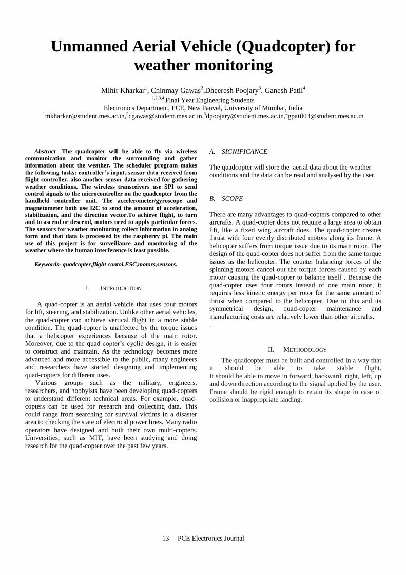
Figure 1 Basic block diagram of a Quad-copter
To achieve flight, two of the motors must apply
downward force and the other two motors have to apply an
upward force. To turn, one pair (left or right side) of motors
slows down to turn the copter. To ascend, all motors will
increase in speed, and will all decrease in order to descend. To
move forward, the front two motors will decrease while the
back two motors will increase. And vice versa in order to
move in a backwards direction.
III. FLYING MECHANISM OF QUADCOPTER
A quad-copter consists of four motors evenly distributed
along the quad-copter frame as can be seen in Fig. 2 below.
The circles represent the spinning rotors of the quad-copter
and the arrows represent the rotation direction. Motors one
and three rotate in a clockwise direction using pusher rotors.
Motor two and four rotate in a counter-clockwise direction
using puller rotors. Each motor produces a thrust and torque
about the center of the quad-copter. Due to the opposite
spinning directions of the motors, the net torque about the
center of the quad-copter ideally zero, producing zero angular
acceleration. This eliminates the need for yaw stabilization. A
vertical force is created by increasing the speed of all the
motors by the same amount of throttle. As the vertical forces
overcome the gravitational forces of the earth, the quad-copter
begins to rise in altitude.
Fig. 2 shows the vertical movement of the quad-copter.
As above, the circles represent the spinning rotors, the larger
arrows represent the direction the rotors are spinning, and the
black arrows represent the forces caused by the spinning
rotors. Pitch is provided by increasing (or decreasing) the
speed of the front or rear motors. This causes the quad-copter
to turn along the x axis. The overall vertical thrust is the same
as hovering due to the left and right motors; hence only pitch
angle acceleration is changed.
Figure 2 Quad-copter: Motor rotation directions
Figure 3 Quad-copter: Vertical thrust movement.
Fig. 3 shows an example of pitch movement of a quad-
copter. As the front motor slows down, the forces created by
the corresponding rotor are less than the forces created by the
back rotor. These forces are represented by the blue arrows.
These forces cause the quad-copter to tip forward and this
movement is represented by the red arrow. Roll is provided by
increasing (or decreasing) the speed of the left rotor speed and
right motors. This causes the quad-copter to turn along the y
axis. The overall vertical thrust is the same as hovering due to
the front and back motors; hence only roll angle acceleration
is changed.

15 PCE Electronics Journal
Figure 4 Quad-copter: Pitch movement
Figure 5 Quad-copter: Roll movement
Fig. 4 shows an example of roll movement of a quad-
copter. As the right motor slows down, the forces created by
the corresponding rotor are less then the forces created by the
left rotor. These forces are represented by the blue arrows.
This causes the quad-copter to tip to the right and this
movement is represented by the red arrow.
Figure 6 Quad-copter: Yaw movement
Yaw is provided by increasing (or decreasing) the speed
of the front and rear motors or by increasing (or decreasing)
the speed of the left and right motors. This causes the quad-
copter to turn along its vertical axis in the direction of the
stronger spinning rotors. As the front and back motor slows
down, the forces created by the corresponding rotors are less
than the forces created by the left and right rotors. The quad-
copter will begin to rotate in the same direction as the faster
spinning rotors due to the difference in torque forces. This
movement is represented by the red arrow.
IV. WEATHER MONITORING
There is an increased focus on the changing weather and
climate conditions.It is necessary to monitor the weather and
to be prepared for changing weather.The weather conditions
can be monitored by studying the changes in factors like
temperature,humidity,light intensity etc. This data can be
studied and analysed by the user to understand the weather
better.
In this project Raspberry pi 2 is used for weather
monitoring. The sensors are interfaced with the raspberry
pi.The sensor data can be either sent to the user or can be
stored in the raspberry pi itself. Raspberry pi has 900 MHz
ARM Cortex A7 CPU and 1GB memory.17 GPIO peripheral
pins makes it easy to interface the sensors.It requires 5V as
supply.
The sensors used are LDR for measuring light
intensity,DHT11 for temperature and humidity
measurement..The sensors are interfaced with raspberry pi and
the data can be viewed on serial monitor or can be stored in
the raspberry pi or memory card or can be sent to user over
wireless interface like wifi or internet.
V. ADVANTAGES AND DISADVANTAGES
Advantages:
The Quadcopter can reach places where humans can’t
reach.
Various sensors can be used for monitoring and
analyzing data.
It is easy to learn and control the UAV.
Disadvantages
The flight time depends on the battery capacity and
the range depends on the transceiver range,both of
them are limited

16 PCE Electronics Journal
VI. APPLICATIONS
During a natural calamity,the quadcopter can be used to
survey and monitor the affected area.
There are various educational,military and even
outer space applications of the quadcopter.
VII. CONCLUSION
The project focuses on the designing and building of
the quadcopter.There are other ways for weather
monitoring which are being used, but use of quadcopter
will provide simple and easy way for the users for
analysis of weather as it can be controlled with ease and
can access remote locations.
REFERENCES
[1] Jaidev S, Rishika K, Srinivasa R, Sundus A,Modelling and
simulation of Multi- Quadcopter Concept, ijert, Oct 2016
[2] https://irjet.net/archives/V3/i4/IRJET-V3I4233.pdf
[3] http://ece.eng.umanitoba.ca/undergraduate/ECE4600/ECE4600/Archive/2012/2012_2013_Final_Reports/G11_Final_Report_2013.pdf
[4] https://www.dnvgl.com/oilgas/joint-industry-projects/sustainability/framework-for-environmental-condition-monitoring.html
[5] http://www.mwm.im/ResearchFiles/Papers/StabilityAndControlOfAQuadrocopterDespiteTheCompleteLossOfOneTwoOrThreePropellers.pdf

17 PCE Electronics Journal
Digital image inpainting using single image
Aishwarya Pillai 1, Madhura Khanvilkar
2, Smriti Sivadas
3, K.Vinod
4
1,2,3,4 Final Year Engineering Students
Electronics Department, PCE, New Panvel, University of Mumbai, India
Abstract—Image Inpainting or Image completion is technique
which is used to recover the damaged image and to fill the
regions which are missing in original image in visually plausible
way. There are various approaches to reconstruct images using
inpainting. Based on the efficiency of the technique it was decided
to implement the patch based inpainting algorithm having
isophote driven patch-based texture synthesis at core. In this
work, the algorithm of inpainting using patch matching is
presented that attempts to replicate the basic techniques used by
professional restorators[2]. After the user selects the regions to be
restored, the algorithm automatically fills-in these regions with
information surrounding them. Patch-based filling improves
execution speed. The fill-in is done in such a way that structure
information arriving at the region boundaries is completed
inside. A new method of filling and updating the target region is
introduced. We call it as patch based inpainting. It overcomes the
disadvantages of earlier approaches. Numbers of examples on
real and synthetic images demonstrate the effectiveness of our
algorithm. Robustness with respect to the shape of selected target
region is also demonstrated. Our results compare to those
obtained by existing techniques.
Keywords: Object removal, region filling, patch-matching,
patch based inpainting, simultaneous texture and structure
propagation, isophote.
I. INTRODUCTION
Inpainting, the technique of modifying an image in an
undetectable form, it is art which is used from the ancient
year. Applications of this technique include rebuilding of
damaged photographs & films, removal of superimposed text,
removal/replacement of unwanted objects, red eye correction,
image coding. In image inpainting technique the user first
selects the region which we want to recover and then he
selects the portion from the source region which is more
promising in the sense of matching the information and
closely identical to the original image, the selected region is
also called as patch[1]. The selected patch is applied to
damaged image, after that we get the result which we want. In
past the inpainting was performed by two classes of
algorithms (i) “diffusion based inpainting” and (ii) “texture
synthesis”. If we are trying to define the inpainting technique
then the first thing come in to mind is that this algorithm try to
fill the regions by collecting the information from the
available environment of that source region, it is trying to
form the image which is nearly identical to the original image
and found the close identity to the original image. The image
design with this technique is alternative to the original image
but this technique is such accurate that the person who is
unaware of original image will not able to detect that we have
reconstruct the image. Inpainting is not only to recover the
images which got damaged but also the technique to remove
unwanted objects from the image. This technique remove the
cracks from the image, fills the missing part from the image,
remove the text, dates etc.
A. SIGNIFICANCE
This algorithm not only recovers the images which got
damaged but also removes unwanted objects , cracks, dates etc from the image, fills the missing part from the image.
B. SCOPE
Inpainting is used for reconstructing lost or deteriorated parts of images and videos. Used in computer graphics, in
preserving the historical heritage and eliminating the unwanted objects.
II. METHODOLOGY
Exemplar based inpainting is the approach is used for inpainting. In this approach the missing region is filled with the information from surrounding known region at patch level.
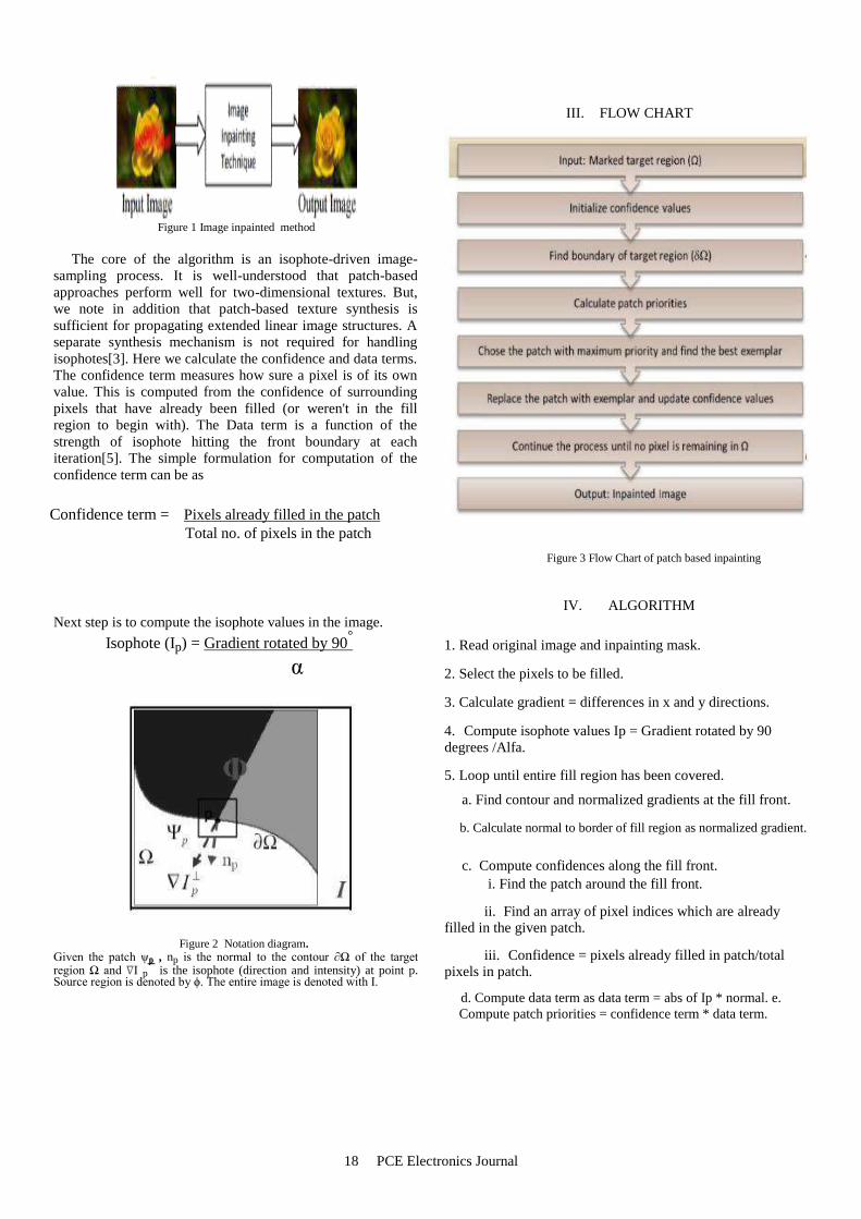
It follows three steps: 1. Priorities of each patch are computed. 2. Selection of the best patch. 3. Filling order.
The block diagram is as shown in the figure 1. At input of
the digital processor original image is taken, then a target
region is being selected and this target region is inpainted
using features around it. And then desired inpainted image is
obtained at the output of the processor.
18 PCE Electronics Journal
III. FLOW CHART
Figure 1 Image inpainted method
The core of the algorithm is an isophote-driven image-
sampling process. It is well-understood that patch-based
approaches perform well for two-dimensional textures. But,
we note in addition that patch-based texture synthesis is
sufficient for propagating extended linear image structures. A
separate synthesis mechanism is not required for handling
isophotes[3]. Here we calculate the confidence and data terms.
The confidence term measures how sure a pixel is of its own
value. This is computed from the confidence of surrounding
pixels that have already been filled (or weren't in the fill
region to begin with). The Data term is a function of the
strength of isophote hitting the front boundary at each
iteration[5]. The simple formulation for computation of the
confidence term can be as
Confidence term = Pixels already filled in the patch
Total no. of pixels in the patch
Figure 3 Flow Chart of patch based inpainting
IV. ALGORITHM
Next step is to compute the isophote values in the image.
Isophote (Ip) = Gradient rotated by 90°
α
Figure 2 Notation diagram.
Given the patch ψp , np is the normal to the contour ∂Ω of the target region Ω and ∇I p
is the isophote (direction and intensity) at point p.
Source region is denoted by ϕ. The entire image is denoted with I.
1. Read original image and inpainting mask. 2. Select the pixels to be filled. 3. Calculate gradient = differences in x and y directions. 4. Compute isophote values Ip = Gradient rotated by 90
degrees /Alfa. 5. Loop until entire fill region has been covered.
a. Find contour and normalized gradients at the fill front.
b. Calculate normal to border of fill region as normalized gradient.
c. Compute confidences along the fill front.
i. Find the patch around the fill front.
ii. Find an array of pixel indices which are already filled in the given patch.
iii. Confidence = pixels already filled in patch/total pixels in patch.
d. Compute data term as data term = abs of Ip * normal. e.
Compute patch priorities = confidence term * data term.

19 PCE Electronics Journal
f. Find patch with maximum priority.
g. Find patch that minimizes error.
i. Extract the inputs. ii. Reject the patches having a region to be
filled. iii. Find the patch which minimizes the sum
squared error (SSE) between two patches. h. Copy image data from patch that minimizes error to patch
with maximum priority.
i. Update fill region.
j. Propagate confidence and isophote values.
V. RESULTS
(a) (b)
(c) (d)
Figure 4 Result of inpainted image
(a) Mask image. (b) the confidence term (c) the data term (d) resulting image of filling all packets.
(a) (b)
Figure 5 Removal of an object from the picture
(a) (b)
Figure 6 Removal of the unwanted object.
(a) (b)
Figure 7 Image Reconstruction.
(a) (b)
Figure 8 Removal of logo from the image
VI. COMPARISON WITH EXISTING TECHNOLOGY
The previous techniques that were used in inpainting includes Total Variational (TV) Model which uses an Euler-Lagrange equation coupled with anisotropic diffusion to maintain the isophotes directions. It is very important to know the Curvature-Driven Diffusion (CDD) model enhances the
20 PCE Electronics Journal
TV method to drive diffusion along the isophotes directions and thus allows inpainting of thicker regions. But these methods mainly deal with structure reconstruction in the images. They fail to restore the images containing more textured areas. The Patch based Inpainting which is currently used technique is more appropriate. It solves the inpainting problem by combining the two approaches- structure and texture inpainting. Simultaneous propagation of texture and structure information is achieved by a single, efficient algorithm. The success of structure propagation, however, is highly dependent on the order in which the filling proceeds. It is a best-first algorithm in which the confidence in the synthesized pixel values is propagated in a manner similar to the propagation of information in inpainting[4]. Hence, we have studied in detail about the algorithms which were being proposed for the digital image inpainting and also comparison with the existing techniques in which the patch based inpainting is more suitable for image inpainting. This algorithm results in preservation of edge sharpness, no dependency on image segmentation and balanced region filling to avoid overshooting artifacts.
VII. ADVANTAGES This implementation needs only the image with
marked fill region compared to the earlier implementations which required degraded image and inpainting mask image with marked fill region as input images.
Algorithm is robust towards changes in shape and topology of the target region as demonstrated in results section, together with other advantageous properties such as preservation of edge sharpness, no dependency on image segmentation and balanced region filling to avoid over-shooting artifacts.
Patch-based filling helps achieve speed efficiency, accuracy in the synthesis of texture and accurate propagation of linear structures.
IX. APPLICATIONS
REFERENCES
[1] Marcelo Bertalmio ,Guillermo Sapiro ,Vicent Caselles ,Coloma Ballester
“Image Inpainting” Proceedings of SIGGRAPH 2000, pp. 417-424. ACM Press, New York (2000).
[2] Manuel, M. Oliveira, Brian Bowen, Richard McKenna ,Yu-Sung Chang
“Fast Digital Image Inpainting” Appeared in the Proceedings of the International Conference on Visualization, Imaging and Image Processing
(VIIP 2001), Marbella, Spain. September 3-5, 2001.
[3] Mohiy M. Hadhoud, Kamel. A. Moustafa and Sameh. Z. Shenoda “Digital Images Inpainting using Modified Convolution Based Method”
International Journal of Signal Processing, Image Processing and Pattern
Recognition. [4] Noori, S. Saryazdi A Nd H. Nezamabadi-Pour “A Bilateral Image
Inpainting” IJST, Transactions of Electrical Engineering, Vol. 35, No. E2, pp 95-108.
[5] Jing Xu, Daming Feng, Jian Wu, Zhiming Cui “An Image Inpainting
Technique Based on 8-Neighborhood Fast Sweeping Method” 2009 International Conference on Communications and Mobile Computing.
Some of the common applications are removal of superimposed text like dates, subtitles, or publicity,
image restoration, scratch removal. This can be used
for removal of entire objects from the image as presented in results. Image compression is one of the
new emerging application of inpainting. Image can
be transmitted removing some data and can be reconstructed at receiver using inpainting. It can be
also used in security applications for hiding important places in satellite images.

21 PCE Electronics Journal
VOICE GUIDING SYSTEM FOR DISABLED
PERSON USING ULTRASONIC SENSOR
Bhavesh Vijay Patil1, Shubham Tanaji Patil
2, Vijay Chandrakant Rasal
3, Samir Shankar Bobade
4
1,2,3,4 Final Year Engineering Students
Electronics Department, PCE, New Panvel, University of Mumbai, India [email protected],
Abstract— The paper describes ultrasonic blind stick with
GPS tracking system. Traditionally visually impaired people
used a stick to find out if any obstacles are present in front of
them. But this stick is inefficient in various aspects and the
person using it has to face several problems. The objective of this
project is to provide the visually impaired abetter navigational
tool. The ultrasonic blind walking stick is way more advanced
than the traditional walking stick as the use of sensors makes
object detection easier.GPS system provides the information
regarding to his current location. Thus this system allows for
obstacle detection as well as getting the live GPS data on server
for tracking blind person. This paper discuss about how this stick
is built and how it will help blind people. There are various
methods to do it and we are using helpful concepts from each
paper.
Keywords- Ultrasonic, GPS
1. INTRODUCTION
In the study of previously developed systems and analysis
of it, let us to define a newly equipped system which could
overcome the disadvantages of the previous systems. So
therefore using the existing technologies we provide a better
solution to the stated problem.
There are so many blind people in the society, who are
suffering from exercising the basic things of daily life and that
could put lives at risk while travelling. There is a necessity
these days to provide security and safety to blind people.
There have been few devices developed so far to help the
blind people. The blind stick is integrated with ultrasonic
sensor along with GPS. Our proposed project first uses
ultrasonic sensor to detect obstacles without touching it using
ultrasonic waves. On sensing obstacles the sensor passes this
data/8 to the microcontroller. The microcontroller then
processes this data and calculates if the obstacle is close
enough. If the obstacle is far the circuit does nothing but If
the obstacle is close the microcontroller sends a signal to
sound a Voice module in any language.
Thus this system allows for obstacle detection as well as
finding stick if misplaced by visually disabled person.
Ultrasonic sensor is used to detect any obstacle in front of
blind person. It has Detection Distance of 2cm-450cm so
whenever there is some obstacle in this range it will alert the
blind person. So person can be aware of it & Voice module
will ring and person can get idea where the stick is placed.
One more feature is that the GPS systems which can use for
tracking the blind person location which feeds live data on
server.
Figure 1 Blind Person Crossing Road
Figure 2 Need of Help

22 PCE Electronics Journal
II. METHODOLOGY
A. Ultrasonic Sensor
Ultrasonic transducers: Generating, detecting & processing
ultrasonic signals Ultrasonic sensor is produce the sound
waves above the frequency of human hearing and can be
used in a different variety of applications such as, sonic
rulers, proximity detectors, movement detectors, liquid
level measurement. Ultrasonic Sensor Ranging Module
Ultrasonic sensor module
HC - SR04 provides 2cm - 400cm non-contact
measurement facility, the ranging accuracy can reach to
3mm. The modules contain ultrasonic transmitters, receiver
and control circuit.
The basic principle of work:
(1) Using IO trigger for at least 10us high level signal,
(2) The Module automatically sends eight 40 kHz and
detect whether there is a pulse signal back.
(3) IF the signal back, through high level , time of high
output IO duration is the time from sending ultrasonic to
returning.
Test distance = (high level time×velocity of sound
(340M/S) / 2
Figure 3 Ultrasonic transducers.
B. GPS
The Global Positioning System (GPS), originally Navstar
GPS, is a space-based radionavigation system owned by the
United States government and operated by the United States
Air Force. It is a global navigation satellite system that
provides geolocation and time information to a GPS
receiver anywhere on or near the Earth where there is an
unobstructed line of sight to four or more GPS satellites .The
GPS system does not require the user to transmit any data, and
it operates independently of any telephonic or internet
reception, though these technologies can enhance the
usefulness of the GPS positioning information. The GPS
system provides critical positioning capabilities to military,
civil, and commercial users around the world. The United
States government created the system, maintains it, and makes
it freely accessible to anyone with a GPS receiver .The GPS
concept is based on time and the known position of GPS
specialized satellites. The satellites carry very stable atomic
clocks that are synchronized with one another and with the
ground clocks. Any drift from true time maintained on the
ground is corrected daily. In the same manner, the satellite
locations are known with great precision. GPS receivers have
clocks as well, but they are less stable and less precise. GPS
satellites continuously transmit data about their current time
and position. A GPS receiver monitors multiple satellites and
solves equations to determine the precise position of the
receiver and its deviation from true time. At a minimum, four
satellites must be in view of the receiver for it to compute four
unknown quantities (three position coordinates and clock
deviation from satellite time).
Figure 4 GPS Module
C. Wi-Fi Module (ESP8266)
ESP8266 is high integration wireless SOCs, designed for
space and power constrained mobile platform designers. It
provides unsurpassed ability to embed Wi-Fi capabilities
within other systems, or to function as a standalone
application, with the lowest cost, and minimal space
requirement. ESP8266EX offers a complete and self-
contained Wi-Fi networking solution; it can be used to host
the application or to offload Wi-Fi networking functions
from another application processor. When ESP8266EX
hosts the application, it boots up directly from an external
flash. In has integrated cache to increase the performance
of the system in such applications.

23 PCE Electronics Journal
Figure 5 Wi-Fi Module (ESP8266)
D. Voice Recording Module
Voice Record Module is base on ISD1820, which a
multiple-message record/playback device. It can offers true
single-chip voice recording, no-volatile storage, and
playback capability for 8 to 20 seconds. The sample is 3.2k
and the total 20s for the Recorder. This module use is very
easy which you could direct control by push button on
board or by Microcontroller such as Arduino, STM32,
ChipKit etc. Frome these, you can easy control record ,
playback and repeat and so on.
Figure 6 Voice Recording Module
III. IMPLEMENTATIOM
3.1 Hardware and Mechanical Design
E. Design
Figure 7 Block diagram
As shown above block diagram the object tracking and following robot is consist of four main components AVR Microcontroller, GSM Module , GPS Module, and LCD module
3.2 Software Design
A. Algorithm
Figure 8 Flowchart of working of gsm and gps
B. Software Required
ARDUNIO 1.8.5
The open-source Arduino Software (IDE) makes it easy to
write code and upload it to the board. It runs on Windows,
Mac OS X, and Linux. The environment is written in Java
and based on Processing and other open Source software.
This software can be used with any Arduino board.
KiCad
KiCad is a free software suite for electronic design
Automation (EDA). It facilitates the design of
schematics for electronic circuits and their conversion
to PCB designs.
It features an integrated environment for schematic
capture and PCB layout design. Tools exist within the package
to create a bill of materials, artwork, Gerber files, and 3D
views of the PCB and its components.

24 PCE Electronics Journal
IV. RESULT
A Object tracking and following robot will follow the specific
object that is the object is clicked by android application and
GPS will provide the location of robot LCD will display
longitude and latitude..Etc GSM is used to send and receive
the message to or from user.
V. CONCLUSION
All the studies which had been reviewed show that, there are a
number of techniques for making a ultrasonic blind stick for
blind people. The aim of this paper is to get familiar with the
work done in making walking stick smarter and more helpful.
The literatures related to this topic were reviewed and
analysed. As technology improves these smart sticks need to
be modified. The simulation results are expected for the
ultrasonic sensors, Voice recording module, GPS and
ESP8266. So in this paper wide survey of the work related to
this project is done and we have shortlisted some useful
aspects from each project. This will also help to decide
designing approach.
Figure 9 Using ordinary Cane
Figure 10 Comparison of Ordinary & Electronic Stick
VI. APPLICATIONS
Voice guided vehicles for handicapped
Smart wheel chair based on voice recognition for
handicapped
GPS guided shoes for visually impaired
Military applications
REFERENCES
[1]. Benjamin J. M., Ali N. A., Schepis A. F., ―A Laser Cane for the Blindǁ
Proceedings of the San Diego Biomedical Symposium, Vol. 12, 53-57.
[2]. Osama Bader AL-Barrm International Journal of Latest Trends in Engineering and Technology (IJLTET)
[3]. Smart Cane Assisted Mobility for the Visually Impaired, World Academy
of Science, Engineering and Technology International Journal of Computer, Electrical, Automation,
Control and Information Engineering Vol:6, No:10, 2012
[4]. Lise A. Johnson and Charles M. Higgins, ―A Navigation Aid for the Blind Using Tactile-Visual Sensory Substitution.

25 PCE Electronics Journal
HAND MOTION CONTROLLED ROBOTIC
ARM
Komal Bhand1, Shraddha Bhosle
2, Krinjal Jain
3, Damini G
4
1,2,3,4 Final Year Engineering Students
Electronics Department, PCE, New Panvel, University of Mumbai, India [email protected],
Abstract—nowadays, robots are increasingly being integrated
into working tasks to replace humans especially to perform the
repetitive task. In general, robotics can be divided into two areas,
industrial and service robotics these robots are currently used in
many fields of applications including office, military tasks,
hospital operations, dangerous environment and agriculture.
Besides, it might be difficult or dangerous for humans to do some
specific tasks like picking up explosive chemicals, defusing bombs
or in worst case scenario to pick and place the bomb somewhere
for containment and for repeated pick and place action in
industries. Therefore a robot can replace human to do work.
There are certain techniques being implemented to control the
movement of a robotic arms like Motion sensors & markers,
vision systems etc. Use of accelerometer as a gesture recognition
device is becoming quite popular due to its small size and low
moderate cost.
Keywords--Gestures, robotic arm, accelerometer.
I. INTRODUCTION
Robotics is a current emerging technology in the field of
science. Robotics is the new emerging booming field, which
will be of great use to society in the coming years. These days
many types of wireless robots are being developed and are put
to varied applications and uses. This robot is operated &
controlled wirelessly with the help of hand gestures which
transmits signals to the robot through an auto device fixed on
the gloves put on hands rather than controlling it manually
through a conventional remote controller. The Robot moves
and acts in the manner depending on the gestures made by the
fingers and hand from a distance. The robot moves in up,
down, left or right directions and picks up objects from one
place and keeps at another desired place as directed by the
movements of fingers and hand. The project is based on wired
communication.
A SIGNIFICANCE
This machine performs whatever we want to do recognizing
our gestures thereby reducing human efforts and time.
B SCOPE
The project is built on a wired model. It could further be
developed to work on wireless communication, thus allowing
the user to move in an even easier unrestricted manner. A
clamper can be connected on the motor M6 which will allow
the movements of the palm and allow picking and placing of
objects. Currently the accelerometer signal is being processed
via a digital computer; this could be eliminated by using a fast
microprocessor such as ARMv7, etc. It could also be possible
to eliminate the ATmega32 altogether when ARMv7 is being
used. The microprocessor could take the input from the
accelerometer and smoothen it and then generate the
corresponding PWM signal itself to actuate the servo motors.
II. METHODOLOGY
In this Project, the hardware and software function are
combined to make the system reliable. The Arduino will be
interfacing the robot with the sensor i.e. 3 axis accelerometer
and the actuators i.e. servo motors which will control the
movement of the robot respectively. The model consists of the
transmitting and receiving units. Main components used are as
Follows –
1. Accelerometers (Sensor)
2. Servo Motors (Actuator)
3. Arduino Nano (Data Acquisition)
4. Arduino UNO (Controller)
3-axis wireless accelerometer mounted on a glove is used
to capture human hand behaviors, and microcontroller
acquired the values in analog form. The 3-axis accelerometers
(ADXL330, Analog Device) is physically rated to measure
accelerations over a range of at least +/- 3g, with a sensitivity
of 300 mV/g and sensitivity accuracy of 10%. The analog
readings from accelerometer can be displayed on a LCD and
analyzed to create a mathematical relation with the PWM
control of motors. The advantage of the accelerometer is that
the values do not change unless there is a change in position.
But the problem with the accelerometer is that it contained

26 PCE Electronics Journal
high level of noise which makes the values inaccurate. So, to
make these values accurate Gyroscope sensor.
III. OBJECTIVE
The main objective of this project is to investigate the
characteristic and performance of the development of robotic
arm to mimic the human hand on manipulating the objects by
introducing the PIC based wireless system. Followings are the
additional objective proposed system:
A. To fabricate robot hands, which is capable of applying
independent forces to a grasped object?
B. To produce a wireless artificial robotic hand which mimic
the human hand on manipulating the objects as well as
contribute to the solution of robot end effectors grasping
problem and robot reprogramming difficulty.
C. To control the movement by using glove to integrate with
hand and teleoperate by RF wireless module.
D. To design control parts of the robot hand by
PIC/AVR/ARM family midrange microcontroller as
controller.
IV.SENSORS AND CONTROLLER
A)SERVO MOTORS(4):
Servo motors are a type of electromechanical actuators that
do not rotate continuously like DC/AC or stepper motors;
rather, they are used to position and hold some object. They
are used where continuous rotation is not required so they are
not used to drive wheels (unless a servo is modified). Servos
also employ a feedback mechanism, so it can sense an error in
its positioning and correct it. This is called servomechanism.
Figure 1 Servo Motors
B)ACCELEROMETER
A kind of sensor works by giving analog data in x, y, z
directions
Figure 2 Accelerometer
C)FLEX SENSORS
Strip of carbon material having metal pads inside it. Measures amount of deflection or bending.
Figure 3 Flex Sensors
D)ARDUINO BOARD
Microcontroller board based on ATMEGA328P. It has 14
digital input/output pins.
Figure 4 Arduino Board
V.WORKING
In this project, a mobile robot that is controlled by the
gestures made by the hand is designed. The working of the
robot is explained here. As mentioned earlier, the gesture
controlled robot is a wireless operated robot and has two parts:
Transmitter and Receiver. When the robot is powered on, the
transmitter part, which consists of Arduino, Accelerometer,
Encoder and RF Transmitter, will continuously monitor the
accelerometer sensor. This data is captured by the Arduino,
which transmits appropriate data to the Encoder, based on the
orientation of the Accelerometer. The parallel data received by
the encoder is converted into serial data and this serial data is
transmitted by the RF Transmitter. At the receiver section, the
RF Receiver receives the serial data and transmits to Decoder
IC. The Decoder will convert the serial data to parallel data
and this parallel data is given to the motor driver IC. Based on
the data, the movement of the motors, and hence the
movement of the robot is defined. Working is divided into 2
parts-

27 PCE Electronics Journal
INPUT SIDE
Figure 5 Input Side
OUTPUT SIDE
Figure 6 Output Side
FLOW DIAGRAM:
The basic working of the machine can be explained with the help of a flow diagram:
Figure 7 Flow Diagram
The transmitting unit, as shown in figure- 5 is at human end
can be mounted on a glove which is worn by human hand. The
unit contains an accelerometer, a arduino for processing the
signals and analog values from accelerometer and a RF
transmitter to transmit codes against different ADC values
from MCU (arduino).
The values are being transmitted wirelessly at receiving
end, which consists of a RF receiver, & a arduino for
controlling servo motors. The whole arrangement is placed on
a mobile platform with wheels to facilitate movement from
one place to another. The mobile platform can be controlled
using a wireless remote control.
VI. ADVANTAGES
It is easy to design as all components are easily available.
It is portable & can be placed anywhere.
Due to wireless communication data rate is faster & ease
of operation.
Microcontroller can be reprogrammed if any modification
is required.
There is no need of lengthy wires.
VII.DISADVANTAGES
Precise programming is needed.
It replace human workers so unemployment increases.
Robot will only respond when you move your hand.
VIII.APPLICATIONS
It is useful for moving heavy loads from one place to
another.
It is general purpose device for better leaving.
It is useful in Military applications.
It plays a major role in helping very weak people in their
daily life.
It can be used as a assistance for physically challenged
people.

28 PCE Electronics Journal
IX.CONCLUSION
The objectives of this project has been achieved which was
developing the hardware and software for an accelerometer
controlled robotic arm. From observation that has been made,
it clearly shows that its movement is precise, accurate, and is
easy to control and user friendly to use. The robotic arm has
been developed successfully as the movement of the robot can
be controlled precisely. This robotic arm control method is
expected to overcome the problem such as placing or picking
object that away from the user, pick and place hazardous
object in a very fast and easy manner.
ACKNOWLEDGEMENT
We would like to express our sincere gratitude to our HOD
Prof. R. H. Khade ,our project guide Prof. Padmaja Bangde
and our project coordinator Prof. Ujwal Harode who have
significantly guided and encouraged us to proceed with this
newly proposed idea. We would also like to thank our
principal Dr. S. M. Joshi for providing us with all the facilities
and environment to bring out the best of our capabilities
REFERENCES
[1] Pattnaik, Ashutosh and Ranjan, Rajiv (2013) Robotic Arm Control
through Human Arm Movement using Accelerometers. B.Tech thesis,109EI0297
[2] J. Aleotti, A. Skoglund and T. Duckett, “Position teaching of a robot arm
by demonstration with a wearable input device,” in International Conference on Intelligent Manipulation and Grasping (IMG04), Genoa, Italy, July 1-2,
2004
[3] I. Mihara, Y. Yamauchi, and M. Doi, “A real-time vision-based interface using motion processor and applications to robotics,” in Systems and
Computers in Japan, vol. 34, pp. 10-19, 2003.
[4] Pedro Neto, J. Norberto Pires, AP Moreira RO-MAN -2009”Accelerometer based control of and industrial robotic arm.

29 PCE Electronics Journal
Spinning LED Display using Arduino
Sukhpreet Singh Bindra1, Vijaya Chintala
2, Pratik Chavan
3, Faizul Shaikh
4
1,2,3,4 Final Year Engineering Students
Electronics Department, PCE, New Panvel, University of Mumbai, India [email protected],
Abstract— A spinning display is a device that creates a stable
image which is constructed by a stick turning around its center
which is filled with led. By this way, using limited number of
LEDs, we can construct an image in the form of normal displays.
As far as the conventional led displays are concerned, the
revolutionary approach pursued by this type of display can be
noticed remarkably. This type of display will create images using
one or small number of columns of LED(s) placed on a plate. The
plate is attached to a motor which will cause its turn around a
circular orbit. By this way, the LED(s) turning around this orbit
will create an image for human eye, using the fact that the human
eye is not able to clearly distinguish movements beyond a
particular frequency.
Keywords—spinning, display, LED, motor, eye
I. INTRODUCTION
Spinning LED Display consists of LED(s) on a clad turning
around an orbit to create 24-bit colored display. The
Persistence Of Vision (POV) as a visual art form, using an
array of lights, waved back and forth in space, with the lights
controlled by wearable computer. POV is the commonly used
term to describe the optical illusion whereby multiple discrete
images blend into a single image in the human mind and
believed to be the explanation for motion perception in cinema
and animated films.
A. SIGNIFICANCE
This machine displays designs or patterns given generated for
certain applications like displaying time or advertising
purposes.
B. SCOPE
The scope of this system can be seen in a few numbers of fields:
1. Advertisement: In this modern era there is a growing need of advertising the products and services. People get influenced by good advertisement. Persistence of vision proved to be very effective method for providing a visual image to attract the consumers. Advertisement can be made much more attractive by two dimensions or three dimension visual image.
2. Entertainment: Persistence of vision plays a very vital role in entertainment point of view. It can be used in shopping malls for displaying messages. It can also be used in film industry. Motion pictures are based on the principles of
persistence of vision. The display is like any complex toy. We can make it for fun and diversion by using this application in games and toys.
3. Animation: The persistence of vision is the basic principle of animation. This technique is also used in cartoon animation. Cartoon movies are also result of persistence of vision.
4. Education: If persistence of vision is used in education field it will provide a better way for interactive education. Many concept need to be explained in three dimension view that can be easily demonstrated by the help of this persistence of vision.
II. METHODOLOGY
The main aim of the vending machine is to provide a
display according to the pattern given to its input . The Main Part of the propeller clock is ARDUINO board, which is placed on the base of rotating assembly. When the zero position is represented by the hall sensor, which is placed on the rotating PCB, it will generate a low pulse on the interrupt pin of ARDUINO which results in the generation of desired pattern. Since we are making use of internal program execution EA (External Access) pin has to be made high with the help of VCC.. The anodes of LED(s) are joined together and connected to 5v supply. The spinning display shows things or patterns like digital clock, messages, etc.
III. COMPARISON WITH EXISTING TECHNOLOGY
This project started with a simple principle which is
frequently encountered in our everyday life, which is
Persistence of Vision. This phenomenon makes one feel fast
moving/changing objects to appear continuous. A television is
a common example; in which image is re-scanned every 25
times, thereby appear continuous. Further, a glowing objects if
rotated in a circle at fast speed, it shows a continuous circle.
But if these LED(s) are switched at precise intervals, a steady
display pattern can be shown. Existing systems do employ
POV principle, but for displaying each pixel, individual LED
is used. This results in a huge number of LED(s) even for
small sized displays. By using a propeller type display, LED
count can be kept to a bare minimum. Even 15 LED(s) can
perform a task of over 525 LED(s).

30 PCE Electronics Journal
IV.SENSORS AND CONTROLLER:
A. MICROCONTROLLER:
The microcontroller used is Nano Atmega 328. It lacks
only a DC power jack, and works with a Mini-B USB cable
instead of a standard one. The Arduino Nano can be powered
via the Mini-B USB connection, 6-20V unregulated external
power supply (pin 30), or 5V regulated external power supply
(pin 27). The power source is automatically selected to the
highest voltage source.
The Arduino Nano is a small, complete, and breadboard-
friendly board based on the ATmega328 (Arduino Nano 3.x)
or ATmega168 (Arduino Nano 2.x).
Figure 1 Nano Atmega328 Arduino Board
B. BLUETOOTH MODULE:
HC‐05 module is an easy to use Bluetooth SPP (Serial Port
Protocol) module, designed for transparent wireless serial
connection setup. The HC-05 Bluetooth Module can be used
in a Master or Slave configuration, making it a great solution
for wireless communication. The user can use it simply for a
serial port replacement to establish connection between MCU
and GPS, PC to your embedded project, etc.
Figure 2 Bluetooth module
C. DC MOTOR:
A DC motor is any of a class of electrical machines that
converts direct current electrical power into mechanical
power. The most common types rely on the forces produced
by magnetic fields. Nearly all types of DC motors have some
internal mechanism, either electromechanical or electronic; to
periodically change the direction of current flow in part of the
motor. In this system, the DC Motor of Operational voltage
and most types produce rotary motion; a linear motor directly
produces force and motion in a straight line. The speed is
3000rpm.
Figure 3 DC gear motor
D. RTC MODULE:
The DS1307 serial real-time clock (RTC) is a low-power, full binary-coded decimal (BCD) clock/calendar plus 56 bytes of NV SRAM. Address and data are transferred serially through an I²C, bidirectional bus. The clock/calendar provides seconds, minutes, hours, day, date, month, and year information. The end of the month date is automatically adjusted for months with fewer than 31 days, including corrections for leap year. The clock operates in either the 24-hour or 12-hour format with AM/PM indicator. The DS1307 has a built-in power-sense circuit that detects power failures and automatically switches to the backup supply. Timekeeping operation continues while the part operates from the backup supply.
Figure 4 RTC Module

31 PCE Electronics Journal
E. HALL SENSOR MODULE:
This module is based on the A3144E Hall switch sensor and it is designed to be used in applications requiring magnetic field sensing. It can be used for sensing motor speed, position and more. It features two outputs: AO, the analog signal output and DO, the digital output, after being passed through a voltage comparator LM393. The Hall sensor outputs a low level voltage when magnetic field is detected. The LM393 series was designed to directly interface with TTL and CMOS. When operated from both plus and minus power supplies, the LM393 series will directly interface with MOS logic where their low power drain is a distinct advantage over comparators.
Figure 5 Hall Sensor Module
V.WORKING
The devices which are connected/interfaced with the microcontroller (Arduino) can be represented in a block diagram
As shown below:
A .BLOCK DIAGRAM
Figure 6 Block Diagram
B.FLOW DIAGRAM
The basic working of the machine can be explained with the help of a flow diagram:
. Figure 7 Flow Diagram
The Spinning LED Display works on the principle of
Persistence Of Vision (POV)
When the motor starts rotating, the whole board
rotates with it.
The LEDs start to blink in the pattern provided by the
Arduino board.
The rotation of the motor causes a particular pattern
to be observed.
The RTC module is used to provide real time values
for patterns like time, date, etc.
The Bluetooth module helps in deciding the display
pattern wirelessly.
A magnet is used to check the zero position or the
starting point via the Hall Sensor.

32 PCE Electronics Journal
VI. ADVANTAGES
The Rotating Display is portable in size.
Eliminates the necessity to use many LEDs which
can lead to overlapping of patterns.
Low circuit complexity
VII.DISADVANTAGES
Error in coding can cause abrupt patterns.
Change in speed of the motor would cause the
improper or no formation of the pattern.
VIII.APPLICATIONS
Advertisements
Propeller Clocks
Shopping Malls
.
IX.CONCLUSION
Although digital clocks and other systems are being used
widely nowadays, using this type of display can help in
making the advertising and other system more desirable and
innovative. This type of machine reduces analog circuit
dependency and also provides accurate results.
ACKNOWLEDGEMENT
We would like to express our sincere gratitude to our HOD
Prof. R. H. Khade, our project guide Prof. Ravi. K. Biradar
and our project coordinator Prof. Ujwal Harode who have
significantly guided and encouraged us to proceed with this
newly proposed idea. We would also like to thank our
principal Prof. Dr. S.M.Joshi for providing us with all the
facilities and environment to bring out the best of our
capabilities
REFERENCES
[1]https://www.arduino.cc/en/Tutorial/ShiftOut
[2] https://learn.sparkfun.com/tutorials/serial-peripheral-interface-spi [3]https://ipfs.io/ipfs/QmXoypizjW3WknFiJnKLwHCnL72vedxjQkDDP1mX
Wo6uco/wiki/Persistence_of_vision.html
[4]https://www.allaboutcircuits.com/technical-articles/using-interrupts-on-
arduino/
[5]http://tinkbox.ph/sites/mytinkbox.com/files/downloads/LM393_HALL_EFFECT_MAGNETIC_DETECTOR_SENSOR_MODULE.pdf

33 PCE Electronics Journal
Automated Irrigation System
Vidhi Patel1, Sanjay Podal
2, Abhishek Ninawe
3, Tanmay Pradhan
4
1,2,3,4 Final Year Engineering Students
Electronics Department, PCE, New Panvel, University of Mumbai, India
Abstract—the project aims to develop an irrigation system
keeping a touch with modern technology. The system would be
automatic so as to provide ease to the user and the project will
incorporate various sensors, raspberry pi, arduino & zigbee.
Agriculture is one of the most important branch of science
directly concerning human survival yet it is one of the least
technically advanced fields. Our project aims to optimize
irrigation so as the user not only experiences ease but also can
make informed decisions based on the data provided by our
system. A wireless sensor network is setup in the field. The
network will include sensors like, moisture sensor, pyranometer,
water level sensor, and soil temperature sensor and rainfall
detector. The data from the WSN will be sent to the raspberry-Pi
module using zigbee communication which will control the pump
nozzles. The user will also get data via GSM module. The
irrigation system will provide water to the crops using pumps.
The water requirement will be decided by refreshing the data
provided by the WSN. The irrigation system will be fully
automated but the user can choose to manually control the
system if user wishes. The system will not only provide the user
with an efficient irrigation system but will also give in depth data
analysis based on which information can be made.
Keywords-Irrigation, Rasberry pi
I. INTRODUCTION
A. Literature Survey
In India, water resource is in severe shortage and
agricultural water consumption accounts for about 70% of the
total water consumption. One important way to improve the
utilization rate of irrigation water is to implement precise
controlled information on the basis of water crops demand
data. In the modern irrigation systems, the most significant
advantage is that water is supplied near the root zone of the
plants drip by drip due to which a large quantity of water is
saved. At the present era, the farmers have been using
irrigation technique in India through the manual control in
which the farmers irrigate the land from time to time. This
process sometimes consumes more water and time. Automatic
irrigation scheduling consistently has shown to be valuable in
water use efficiency with respect to manual irrigation based on
direct soil water measurements. The aim of the
implementation is to demonstrate that the automatic irrigation
can be used to reduce water use. The implementation is a
automated irrigation system that consists of a distributed
wireless network of soil moisture and temperature sensor.
Automated Irrigation System is one of the methods that saves
water.
B. Problem Statement
The project aims to develop an irrigation system keeping a
touch with modern technology. The system would be
automatic so as to provide ease to the user and the project will
incorporate various sensors, raspberry pi, arduino & RF
module. A wireless sensor network is setup in the field. The
network will include sensors like, moisture sensor, water level
sensor and rainfall detector. The data from the WSN will be
sent to the raspberry-Pi module using RF communication
module which will control the pump nozzles. The user will
also get data via GSM module. The irrigation system will provide water to the crops using
pumps. The water requirement will be decided by refreshing
the data provided by the WSN. The irrigation system will be
fully automated but the user can choose to manually control
the system if user wishes.
II. METHODOLOGY
A. (RPI). Raspberry pi
Figure 1 Raspberry Pi
The Raspberry Pi is credit-card sized computer. It is capable of
doing everything you’d expect a desktop computer to do.
There are different models of Raspberry Pi from Raspberry Pi
0 to Raspberry Pi 3. In this project we are using Raspberry Pi
Model 3 B+. A Raspberry Pi with smaller size and
reduced input/output (I/O) and general-purpose
input/output (GPIO). All models feature a Broadcom system
on a chip (SoC), which includes an ARM compatible central
processing unit (CPU) and an on-chip graphics processing
unit (GPU, a Video Core IV).

34 PCE Electronics Journal
B. ARDUINO
Figure 2 Arduino uno board
The Arduino UNO is a widely used open-source
microcontroller board based microcontroller. The board is
equipped with sets of digital and analog input/output (I/O) pins
that may be interfaced to various expansion boards. The board
features 14 Digital pins and 6 Analog pins. The
Arduino/Genuino Uno has a number of facilities for
communicating with a computer, another Arduino/Genuino
board, or other microcontrollers. The ATmega328 provides
UART TTL (5V) serial communication, which is available on
digital pins 0 (RX) and 1 (TX)
C. GSM MODULE
Figure 3 GSM module
GPRS/GSM Module is an ultra compact and reliable wireless
module. It is a breakout board and minimum system of
SIM900 Quad-band GSM/GPRS module. It can communicate
with controllers via AT commands. This module support
software power on and reset.
The GPRS is configured and controlled via its UART using
simple AT commands. Just connect on the Arduino/Raspberry
Pi/AVR/PIC/ARM/FPGA board, you could easy to use AT
command control it.
D. SENSORS
Different Wireless sensors:-
1. Moisture sensor This moisture sensor uses the two probes to pass current
through the soil, and then it reads that resistance to get the
moisture level. More water makes the soil conduct electricity
more easily (less resistance), while dry soil conducts
electricity poorly.
Specifications
Output voltage signal: 0~4.2v
Current: 35mA
Pin definition:
Analog output (Blue wire)
GND (Black wire)
Power(Red wire)
Size: 60x20x5mm
Figure 4 Moisture sensor
2. Rainfall detector sensor
Figure 5 Rainfall detector sensor
Rain sensor module is an easy tool for rain detection.. Works
on the switching principle. The module features, a rain board
and the control board that is separate for more convenience,
power indicator LED and an adjustable sensitivity though a
potentiometer. The analog output is used in detection of drops
in the amount of rainfall.
Specifications
Working voltage- 5V
Output format: Digital switching output (0 and 1) and analog
voltage output AO
With bolt holes for easy installation Small board PCB size: 3.2cm x 1.4cm
Uses a wide voltage LM393 comparator
3. FLOAT SENSOR
A float switch is a type of level sensor, a device used to detect
the level of liquid within a tank. The switch may be used to
control a pump, as an indicator, an alarm, or to control other
devices.

35 PCE Electronics Journal
Figure 6 .Float sensor
E. RF MODULE
The RF modules are very small in dimension and have a wide
operating voltage range i.e. 3V to 12V. RF modules are 433 MHz RF transmitter and receiver
modules. The transmitter draws no power when transmitting
logic zero while fully suppressing the carrier frequency thus
consume significantly low power in battery operation. When
logic one is sent carrier is fully on to about 4.5mA with a
3volts power supply. The data is sent serially from the
transmitter which is received by the tuned receiver.
Transmitter and the receiver are duly interfaced to two
microcontrollers for data transfer.
Figure 7 RF Module
III. IMPLEMENTATION
3.1 Hardware and Mechanical Design
A. Design
Figure 8 Block diagram of Automated Irrigation System
B. Assembly
We have two controllers and 3 sensors on which we can
assemble the project. We made RF Module for wireless
communication purpose one will transmit the data 1.e sensor
information and other will work on receiver for action purpose
on field. Again we have monitor & GSM module for diagnosis
data. It will send message as a status of pump
3.2 Software Design
A. Algorithm
Figure 9 Flowchart of Automated Irrigation System
B. Android software design
A program for Arduino hardware may be written in
any programming language with compilers that produce binary
machine code for the target processor. Atmel provides a
development environment for their 8-bit AVR and 32-
bit ARM Cortex-M based microcontrollers
3.3 Software Required
A. PYTHON
Python, C, C++, Java, Scratch, and Ruby all come installed by
default on the Raspberry Pi. Python is a widely used high-level
programming language for general-purpose programming.
An interpreted language, Python has a design philosophy that
emphasizes code readability and a syntax that allows
programmers to express concepts in fewer lines of code than
might be used in languages such as C++ or Java. The language
provides constructs intended to enable writing clear programs
on both a small and large scale.

36 PCE Electronics Journal
B. C Programming.
C is an imperative procedural language. It was designed to
be compiled using a relatively straightforward compiler, to
provide low-level access to memory, to provide language
constructs that map efficiently to machine instructions, and to
require minimal run-time support. Despite its low-level
capabilities, the language was designed to encourage cross-
platform programming. A standards-compliant and portably
written C program can be compiled for a very wide variety of
computer platforms and operating systems with few changes
to its source code. The language has become available on a
very wide range of platforms, from embedded microcontrollers
to supercomputers.
IV. OUTPUT MEASUREMENT
A. GSM MODULE
Figure 10 GSM module
GPRS/GSM Module is an ultra compact and reliable wireless
module. It is a breakout board and minimum system of
SIM900 Quad-band GSM/GPRS module. It can communicate
with controllers via AT commands. This module support
software power on and reset. The GPRS is configured and controlled via its UART using
simple AT commands. Just connect on the Arduino/Raspberry Pi/AVR/PIC/ARM/FPGA board; you could easy to use AT
command control it.
B. Pump
Figure 11 Pump
An irrigation pump does two things; it provides the water flow
rate and the pressure head to make the irrigation system
function properly. It will pump the field when the signal is
received.
V. RESULT
An Automated Irrigation System will sense the different parameter of the field environment by using sensor network and aurdino will send the data to raspberry pi with help of RF module .The raspberry pi will take action of turning on/off of pump and displaying data on monitor .The GSM is used to send the turning on action of pump as message to the user.
VI. CONCLUSION
Using this system, one can save manpower, water to improve
production and ultimately increase profit. The automated
irrigation system is feasible and cost effective for optimizing
water resources for agricultural production. The system would
provide feedback control system which will monitor and
control all the activities of plant growth and irrigation system.
REFERENCES
[1] HemaN, Krishna Kant, “Local Weather Interpolation Using Remote AWSData with Error Corrections Using Sparse WSN for Automated Irrigation
for Indian Farming”, 978-1-4799-5173-4/14/$31.00 ©2014 IEEE.
[2] A.R. AI-Ali, Murad Qasaimeh, Mamoun AI-Mardinia, Suresh Radder and I. A. Zualkernan, “ZigBee-Based Irrigation System for Home Gardens”
Department of Computer Science and Engineering, American University of
Sharjah, UAE 978-1-4799-6532- 8/15/$31.00 ©20 15 IEEE [3] G. Nisha , J.Megala, Velammal institute a/technology ,Chennai, India,
“WIRELESS SENSOR NETWORK BASED AUTOMATED IRRIGATION
AND CROP FIELD MONITORING SYSTEM, 2014 Sixth International Conference on Advanced Computing (ICoAC) 978-1-4 799-8159-
5114/$31.00©20 14 IEEE
[4] Joaquín Gutiérrez, Juan Francisco Villa-Medina, Alejandra Nieto-Garibay, and Miguel Ángel PortaGándara, “Automated Irrigation System Using a
Wireless Sensor Network and GPRS Module,” IEEE TRANSACTIONS ON
INSTRUMENTATION AND MEASUREMENT, VOL. 63, NO. 1, JANUARY 2014.
[5] NPTEL course of introduction to IOT
[6]https://digital.library.unt.edu/ark:/67531/metadc500182/m2/1/high_res_d/thesis.pdf
[7] http://www.rhydolabz.com/wiki/?p=10868 [8] https://www.treehugger.com/gadgets/smart-irrigation-controller-uses-
ground-sensors-and-weather-forecast-optimal-watering.html
[9]http://webcache.googleusercontent.com/search?q=cache:http://people.cs.nctu.edu.tw/~yctseng/papers.pub/book-
zigbeepdf&gws_rd=cr&dcr=0&ei=CXmzWcCTD4ftvgT13ZOoCA
[10] https://computers.tutsplus.com/tutorials/building-a-wireless-sensor-network-in-your-home--cms-19745