Circle detection using discrete differential evolution optimization
15
SHORT PAPER Circle detection using discrete differential evolution optimization Erik Cuevas • Daniel Zaldivar • Marco Pe ´rez-Cisneros • Marte Ramı ´rez-Ortego ´n Received: 3 August 2009 / Accepted: 22 August 2010 / Published online: 12 September 2010 Ó Springer-Verlag London Limited 2010 Abstract This paper introduces a circle detection method based on differential evolution (DE) optimization. Just as circle detection has been lately considered as a funda- mental component for many computer vision algorithms, DE has evolved as a successful heuristic method for solving complex optimization problems, still keeping a simple structure and an easy implementation. It has also shown advantageous convergence properties and remark- able robustness. The detection process is considered similar to a combinational optimization problem. The algorithm uses the combination of three edge points as parameters to determine circle candidates in the scene yielding a reduc- tion of the search space. The objective function determines if some circle candidates are actually present in the image. This paper focuses particularly on one DE-based algorithm known as the discrete differential evolution (DDE), which eventually has shown better results than the original DE in particular for solving combinatorial problems. In the DDE, suitable conversion routines are incorporated into the DE, aiming to operate from integer values to real values and then getting integer values back, following the crossover operation. The final algorithm is a fast circle detector that locates circles with sub-pixel accuracy even considering complicated conditions and noisy images. Experimental results on several synthetic and natural images with varying range of complexity validate the efficiency of the proposed technique considering accuracy, speed, and robustness. Keywords Circle detection Differential evolution Shape detection 1 Introduction The problem of detecting circular features holds paramount importance for image analysis, in particular for industrial applications such as automatic inspection of manufactured products and components, aided vectorization of drawings, target detection and so [1]. Solving object location is commonly approached by two techniques: deterministic techniques, which include the application of Hough trans- form-based methods [2], geometric hashing, and template or model matching techniques [3, 4]. On the other hand, stochastic techniques include random sample consensus techniques [5], simulated annealing [6] and genetic algo- rithms (GA) [7]. Template and model matching techniques have been successfully applied to shape detection among several other [8]. Shape coding techniques and combination of shape properties have also been used to represent such objects. The main drawback is related to the contour extraction step from real images, as it is difficult, for some models, to deal with pose invariance except for very few simple objects. Commonly, the circle detection in digital images is per- formed through the circular Hough transform [9]. A typical Hough-based approach employs an edge detector and uses edge information to infer locations and radius values. Peak detection is then performed by averaging, filtering, and E. Cuevas D. Zaldivar (&) M. Pe ´rez-Cisneros Departamento de Ciencias Computacionales, Universidad de Guadalajara, CUCEI, Av. Revolucio ´n 1500, Guadalajara, Jal, Mexico e-mail: [email protected] E. Cuevas e-mail: [email protected] M. Pe ´rez-Cisneros e-mail: [email protected] M. Ramı ´rez-Ortego ´n Freie Universita ¨t Berlin, Takustrs 9, 14195 Berlin, Germany 123 Pattern Anal Applic (2011) 14:93–107 DOI 10.1007/s10044-010-0183-9
-
Upload
guadalajara -
Category
Documents
-
view
3 -
download
0
Transcript of Circle detection using discrete differential evolution optimization

SHORT PAPER
Circle detection using discrete differential evolution optimization
Erik Cuevas • Daniel Zaldivar • Marco Perez-Cisneros •
Marte Ramırez-Ortegon
Received: 3 August 2009 / Accepted: 22 August 2010 / Published online: 12 September 2010
� Springer-Verlag London Limited 2010
Abstract This paper introduces a circle detection method
based on differential evolution (DE) optimization. Just as
circle detection has been lately considered as a funda-
mental component for many computer vision algorithms,
DE has evolved as a successful heuristic method for
solving complex optimization problems, still keeping a
simple structure and an easy implementation. It has also
shown advantageous convergence properties and remark-
able robustness. The detection process is considered similar
to a combinational optimization problem. The algorithm
uses the combination of three edge points as parameters to
determine circle candidates in the scene yielding a reduc-
tion of the search space. The objective function determines
if some circle candidates are actually present in the image.
This paper focuses particularly on one DE-based algorithm
known as the discrete differential evolution (DDE), which
eventually has shown better results than the original DE in
particular for solving combinatorial problems. In the DDE,
suitable conversion routines are incorporated into the DE,
aiming to operate from integer values to real values and
then getting integer values back, following the crossover
operation. The final algorithm is a fast circle detector that
locates circles with sub-pixel accuracy even considering
complicated conditions and noisy images. Experimental
results on several synthetic and natural images with varying
range of complexity validate the efficiency of the proposed
technique considering accuracy, speed, and robustness.
Keywords Circle detection � Differential evolution �Shape detection
1 Introduction
The problem of detecting circular features holds paramount
importance for image analysis, in particular for industrial
applications such as automatic inspection of manufactured
products and components, aided vectorization of drawings,
target detection and so [1]. Solving object location is
commonly approached by two techniques: deterministic
techniques, which include the application of Hough trans-
form-based methods [2], geometric hashing, and template
or model matching techniques [3, 4]. On the other hand,
stochastic techniques include random sample consensus
techniques [5], simulated annealing [6] and genetic algo-
rithms (GA) [7].
Template and model matching techniques have been
successfully applied to shape detection among several other
[8]. Shape coding techniques and combination of shape
properties have also been used to represent such objects. The
main drawback is related to the contour extraction step from
real images, as it is difficult, for some models, to deal with
pose invariance except for very few simple objects.
Commonly, the circle detection in digital images is per-
formed through the circular Hough transform [9]. A typical
Hough-based approach employs an edge detector and uses
edge information to infer locations and radius values. Peak
detection is then performed by averaging, filtering, and
E. Cuevas � D. Zaldivar (&) � M. Perez-Cisneros
Departamento de Ciencias Computacionales,
Universidad de Guadalajara, CUCEI, Av. Revolucion 1500,
Guadalajara, Jal, Mexico
e-mail: [email protected]
E. Cuevas
e-mail: [email protected]
M. Perez-Cisneros
e-mail: [email protected]
M. Ramırez-Ortegon
Freie Universitat Berlin, Takustrs 9, 14195 Berlin, Germany
123
Pattern Anal Applic (2011) 14:93–107
DOI 10.1007/s10044-010-0183-9

histogramming the transform space. However, such
approach requires a large storage space, given the 3-D cells
needed to cover the parameters (x, y, r), the computational
complexity, and the low processing speed. Moreover, the
accuracy of the extracted parameters of the detected circle is
poor, particularly in the presence of noise [10]. In particular,
for a digital image of significant width and height and den-
sely populated edge pixels, the required processing time for
circular Hough transform makes it prohibitive to be deployed
in real time applications. In order to overcome such a prob-
lem, other researchers have proposed new methods whose
principles differs from classic Hough transform although the
name is somehow kept, for instance, the probabilistic Hough
transforms [11], the randomized Hough transform (RHT)
[12], and the fuzzy Hough transform [13]. Some other
methods that incorporate alternative transforms have been
reviewed by Becker at [14].
Stochastic search methods for the shape recognition in
computer vision such as GA have also offered important
results. In particular, GA has recently been applied to shape
detection through primitive extraction in the work by Roth
and Levine in [7]. Lutton et al. have developed further
improvement on the aforementioned method in [15]. Yao
et al. proposed a multi-population GA to detect ellipses
[16]. In [47], GA has been used for template matching by
applying an unknown affine transformation. Ayala-
Ramirez et al. presented a circle detector based on GA [17],
which can detect multiple circles on real images but fails
frequently in detecting imperfect circles. Recently, Das
et al. in [18] have proposed an automatic circle detector
(AnDE) through a novel optimization method, which
combines differential evolution and simulated annealing.
The algorithm has been able to detect only one circle upon
synthetic images. However, as the algorithm is based on a
non-combinatorial approach (just like the original DE), it
frequently converges to sub-optimal solutions. Moreover,
unstable behaviors within the process of adapting a non-
combinatorial approach in order to solve a combinatorial
problem quite often yield a heavy computing load.
Another example is presented by Rosin et al. in [19]. It
applies soft computing techniques to shape classification. In
the case of ellipsoidal detection, Rosin proposes in [20] an
ellipse fitting algorithm that uses five points. In [21], Zhang
and Rosin extend the algorithm to fit data upon super-ellipses.
The novel evolutionary computation technique known
as differential evolution (DE) has been introduced by Storn
and Price in 1995 [22]. It has gained much attention
yielding a wide range of applications for solving complex
optimization problems. The procedure resembles the
structure of an evolutionary algorithm (EA), but differs in
the way it generates new candidate solutions and the use of
a ‘greedy’ selection scheme. Moreover, DE performs
searching using floating point representations opposing the
binary wording, commonly used by other EA schemes. DE
also takes relevant concepts for ‘larger populations’ from
GAs and ‘self-adapting mutation’ from ESs.
In general, the DE algorithm can be considered as a fast
robust algorithm, which represents an actual alternative to
EA. Considering the advantages of DE over other optimi-
zation methods, it has become more and more popular in
solving complex, nonlinear, non-differentiable, and non-
convex optimization problems. Over the recent years, DE
has been successfully applied to different subjects such as
reservoir system optimization [23], optimal design of shell-
and-tube heat exchangers [24], beef property model opti-
mization problems [25], generation planning problems
[26], distribution network reconfiguration problems [27],
capacitor placement problems [28], induction motor iden-
tification problems [29], optimal design of gas transmission
network [30], and chaotic systems control and synchroni-
zation [31], just to name a few.
An optimization problem is considered to be combinato-
rial as long as its set of feasible solutions is both finite and
discrete, i.e. enumerable; therefore the classical DE cannot
be applied to combinatorial or permutative problems unless a
modification is added [32]. The situation arises from the fact
that crossover and mutation mechanisms invariably change
any given value to a real number, leading to unstable
behaviors [33] and sub-optimal solutions [34]. By truncating
real-valued parameters to their nearest feasible value, DE has
been applied to combinatorial tasks [18]. However, such
solution itself has led to infeasible solutions and long com-
pute times [32, 33]. Over the years, some researchers have
been working on DE combinatorial optimization [35, 36],
concluding that DE may be appropriate for combinatorial
optimization, as it seems effective and competitive in
comparison to other related approaches. Some combinato-
rial-based DE optimization schemes have proved their
effectiveness: the discrete differential evolution (DDE) [37,
43], the relative position indexing approach [38], the
smallest position value approach [39], the discrete/binary
approach [40], and the discrete set handling approach [41].
DDE has evolved from DE, offering better performance for
solving combinatorial problems. In DDE, suitable conver-
sion routines are incorporated into DE, aiming to operate
from integer values to real values in such a way that integer
values can be retrieved after the crossover operation.
This paper presents an algorithm for the automatic
detection of circular shapes from complicated and noisy
images with no consideration of the conventional Hough
transform principles. The detection process is considered to
be similar to a combinatorial optimization problem. The
DDE is then applied to search the entire edge-map for cir-
cular shapes. The algorithm uses the combination of three
non-collinear edge points as candidate circles (x, y, r) in the
edge image of the scene. A new objective function to
94 Pattern Anal Applic (2011) 14:93–107
123

measure the existence of a candidate circle on the edge map
has been proposed following the neighborhood of a central
pixel through the midpoint circle algorithm (MCA) [42].
Guided by the values of this objective function, the set of
encoded candidate circles are evolved using the DDE so that
they can fit into actual circles within the edge map of the
image. The approach generates a sub-pixel circle detector,
which can effectively identify circles in real images despite
circular objects exhibiting a significant occluded portion.
Experimental evidence shows the effectiveness of such
method for detecting circles under various conditions. A
comparison to one state-of-the-art GA-based method [17]
and the annealed differential evolution algorithm (AnDE)
[18] on different images has been included to demonstrate
the superior performance of the proposed method.
This paper is organized as follows: Sect. 2 provides a
brief outline of the classical DE. Section 3 briefly discusses
the combinatorial optimization problem and explains the
DDE approach. In Sect. 4, the circle detection algorithm
based on DDE is assembled. Experimental results for the
proposed approach are presented in Sect. 5 while Sect. 6
discusses some relevant conclusions.
2 Differential evolution algorithm
In recent years, there has been a growing research interest
in the application of evolutionary algorithms for several
fields of science and engineering. The DE algorithm ([22,
23, 44]) is a relatively novel optimization technique that is
able to efficiently solve numerical-optimization problems.
The algorithm has successfully been applied in many dif-
ferent problems while it has gained a wide acceptance and
popularity because of its simplicity, robustness, and good
convergence properties [45].
The DE algorithm is a simple and direct search algo-
rithm based on population that aims for optimizing global
multi-modal functions. Like GA, it employs the crossover
and mutation operators and the selection mechanism. An
important difference between the GA and DE algorithms is
that the GA relies on the crossover operator to provide the
exchange of information among the solutions, building the
best solutions. On the other hand, the DE algorithm relies
on the mutation operation as the main operator and also
employs a non-uniform crossover that takes child vector
parameters from one parent more frequently than from
others. The non-uniform crossover operator efficiently
shuffles information about successful combinations. This
enables the search to focus on the most promising area of
the solution space.
The DE algorithm also introduces a novel mutation
operation, which is not only simple but also significantly
effective. It is based on the differences of randomly sampled
pairs of solutions in the population. The DE algorithm is also
fast, easy to use, very easily adaptable for integer and dis-
crete optimization, and quite effective for nonlinear con-
straint optimization including penalty functions.
The version of DE algorithm used in this work is known
as DE/best/l/exp or ‘‘DE1’’ [22, 23]. Classic DE algorithms
begin by initializing a population of Np and D-dimensional
vectors considering parameter values that are randomly
distributed between the pre-specified lower initial param-
eter bound xj,low and the upper initial parameter bound
xj,high as follows:
xj;i;t ¼ xj;low þ randð0; 1Þðxj;high � xj;lowÞ;j ¼ 1; 2; . . .;D; i ¼ 1; 2; . . .;Np; t ¼ 0:
ð1Þ
The subscript t is the generation index, while j and i are the
parameter and population indexes, respectively. Hence, xj,i,t
is the jth parameter of the ith population vector in
generation t. In order to generate a trial solution, DE
algorithm first mutates the best solution vector xbest,t from
the current population by adding the scaled difference of
two vectors from the current population.
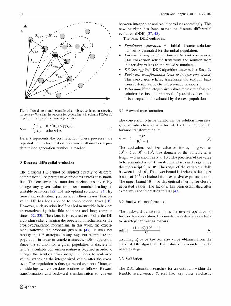
vi;t ¼ xbest;t þ Fðxr1;t � xr2;tÞ; r1; r2 2 1; 2; . . .;Np
� �
ð2Þ
with vi,t being the mutant vector. Vector indices r1 and r2
are randomly selected except that they are all distinct and
have no relation to the population index i (i.e.
r1 = r2 = i). The mutation scale factor F is a positive real
number that is typically less than one. Figure 1 illustrates
the vector-generation process defined by (2).
The next step in the crossover operation is that one or
more parameter values of the mutant vector vi,t are expo-
nentially crossed with those belonging to the ith population
vector xi,t. The result is the trial vector ui,t which is com-
puted by considering element to element as follows:
uj;i;t ¼vj;i;t; if rand (0,1)�Cr or j ¼ jrand;xj;i;t; otherwise:
�ð3Þ
with jrand [ {1, 2, …, D}.
The crossover constant (0.0 B Cr B 1.0) controls the
fraction of parameters to which the mutant vector is con-
tributing in final trial vector. In addition, the trial vector
always inherits the mutant vector parameter according to
the randomly chosen index jrand, assuring that the trial
vector differs by at least one parameter from the vector to
which it is being compared (xi,t).
Finally, the selection operation is used to create the
better solutions. Thus, if the computed cost function value
for trial vector is less than or equal to target vector, then
such trial vector replaces the target vector in the next
generation. Otherwise, the target vector remains in the
population for at least one more generation, yielding
Pattern Anal Applic (2011) 14:93–107 95
123
xi;tþ1 ¼ui;t; if f ðui;tÞ� f ðxi;tÞ;xi;t; otherwise:
�ð4Þ
Here, f represents the cost function. These processes are
repeated until a termination criterion is attained or a pre-
determined generation number is reached.
3 Discrete differential evolution
The classical DE cannot be applied directly to discrete,
combinatorial, or permutative problems unless it is modi-
fied. The crossover and mutation mechanisms invariably
change any given value to a real number leading to
unstable behaviors [33] and sub-optimal solutions [34]. By
truncating real-valued parameters to their nearest feasible
value, DE has been applied to combinatorial tasks [18].
However, such solution itself has led to unstable behaviors
characterized by infeasible solutions and long compute
times [32, 33]. Therefore, it is required to modify the DE
algorithm either changing the population mechanism or the
crossover/mutation mechanism. In this work, the experi-
ment followed the proposal given in [43]. It does not
modify the DE strategies in any way, but manipulate the
population in order to enable a smoother DE’s operation.
Since the solution for a given population is discrete in
nature, a suitable conversion routine is required in order to
change the solution from integer numbers to real-sized
values, retrieving the integer-sized values after the cross-
over. The population is thus generated as a set of integers
considering two conversions routines as follows: forward
transformation and backward transformation to convert
between integer-size and real-size values accordingly. This
new heuristic has been named as discrete differential
evolution (DDE) [37, 43].
The basic DDE outline is:
• Population generation An initial discrete solutions
number is generated for the initial population.
• Forward transformation (Integer to real conversion)
This conversion scheme transforms the solution from
integer-size values to the real-size numbers.
• DE Strategy Full DDE algorithm described in Sect. 3.
• Backward transformation (real to integer conversion)
This conversion scheme transforms the solution back
from real-size values to integer-sized numbers.
• Validation If the integer-size values represent a feasible
solution, i.e. inside the interval of possible values, then
it is accepted and evaluated by the next population.
3.1 Forward transformation
The conversion scheme transforms the solution from inte-
ger-size values to a real-size format. The formulation of the
forward transformation is:
x0i ¼ �1þ xih5
103 � 1ð5Þ
The equivalent real-size value x0i for xi is given as
102 B 5 9 102 \ 103. The domain of the variable xi is
length = 5 as shown in 5 9 102. The precision of the value
to be generated is set at two decimal places as it is given by
the superscript 2 in 102. The range of the variable xi falls
between 1 and 103. The lower bound is 1 whereas the upper
bound of 103 is obtained from extensive experimentation.
The upper bound 103 provides optimal filtering for closely
generated values. The factor h has been established after
extensive experimentation to 100 [43].
3.2 Backward transformation
The backward transformation is the reverse operation to
forward transformation. It converts the real-size value back
to an integer format as follows:
int½x0i� ¼ð1þ x0iÞð103 � 1Þ
5h; ð6Þ
assuming x0i to be the real-size value obtained from the
classical DE algorithm. The value x0i is rounded to the
nearest integer.
3.3 Validation
The DDE algorithm searches for an optimum within the
feasible search-space S, just like any other stochastic
1,r tx
2,r tx
1, 2,r t r t−x x
,best tx
,i tx
,i tv
1, 2,( )r t r tF ⋅ −x x
2x
1x
Fig. 1 Two-dimensional example of an objective function showing
its contour lines and the process for generating v in scheme DE/best/l/
exp from vectors of the current generation
96 Pattern Anal Applic (2011) 14:93–107
123

optimization algorithm. However, in the scope of this
paper, there exist some parameter sets that might not pro-
vide physically feasible solutions to the problem, despite
they belong to the searching space. Moreover, restricting
the search space to the feasible region might be difficult
because the constraints are not that simple to be established
[44]. Therefore, a penalty strategy [44, 45] should be
implemented within the DE algorithm for tackling such a
problem. If a candidate set is not a physically plausible
solution, i.e. yielding an unstable system, then an exag-
gerated cost function value is returned. As this value is
uncommonly large in comparison to usual cost function
values, such ‘‘unstable’’ siblings are usually eliminated on
a single generation.
4 Circle detection using DDE
Circles are represented in this work by means of parameters
of the well-known second degree equation [see (7)], that
passes through three points in the edge space of the image.
Images are preprocessed by an edge-detection step as a
single-pixel edge detection method for object’s contour is
required. This task is accomplished by the classical Canny
algorithm yielding the locations for each edge point. Such
points are the only potential candidates to define circles by
considering triplets. All the edge points in the image are thus
stored in a vector array P ¼ fp1; p2; . . .; pNpg with Np as the
total number of edge pixels contained in the image. So, the
algorithm stores the (xi, yi) coordinates for each edge pixel pi
inside an edge vector.
In order to construct each of the circle candidates (or
individuals within the DE framework), indexes i1, i2 and i3of three edge points must be combined, since the circle’s
contour is assumed to go through points pi1 ; pi2 ; pi3 : A
number of candidate solutions are generated randomly for
the initial population. The solutions will thus evolve
through the application of the DDE algorithm as the evo-
lution over the population takes place until a minimum is
reached and the best individual is considered as the solu-
tion for the circle detection problem.
Applying classic methods based on Hough transform for
circle detection would normally require huge amounts of
memory and consume large computation time. In order to
reach a sub-pixel resolution, an equal feature of the method
presented in this paper, they also consider three edge points
to cast a vote for the corresponding point within the
parameter space. Such methods also require an evidence-
collecting step that is also implemented by the method in
this paper but as the evolution process is performed and the
objective function improves at each generation by dis-
criminating non-plausible circles. Thus, the circle will be
located, with no visits to several image points.
The following paragraphs clearly explain the required
steps to formulate the circle detection task just as one DE
optimization problem.
4.1 Individual representation
Each element C of the population uses three edge points as
elements. In this representation, the edge points are stored
according to one index that is relative to their position
within the edge array P of the image. That will encode an
individual as the circle that passes through the three points
pi, pj, and pk (C = {pi, pj, pk}). Each circle C is repre-
sented by three parameters x0, y0 and r, being (x0, y0) the (x,
y) coordinates of the center of the circle and r its radius.
The equation of the circle passing through the three edge
points can be computed as follows:
ðx� x0Þ2 þ ðy� y0Þ2 ¼ r2; ð7Þ
considering
A ¼x2
j þ y2j � ðx2
j þ y2i Þ 2ðyj � yiÞ
x2k þ y2
k � ðx2i þ y2
i Þ 2ðyk � yiÞ
" #
B ¼2ðxj � xiÞ x2
j þ y2j � ðx2
i þ y2i Þ
2ðxk � xiÞ x2k þ y2
k � ðx2i þ y2
i Þ
" #
; ð8Þ
x0 ¼detðAÞ
4ððxj � xiÞðyk � yiÞ � ðxk � xiÞðyj � yiÞÞ;
y0 ¼detðBÞ
4ððxj � xiÞðyk � yiÞ � ðxk � xiÞðyj � yiÞÞ; ð9Þ
and
r ¼ffiffiffiffiffiffiffiffiffiffiffiffiffiffiffiffiffiffiffiffiffiffiffiffiffiffiffiffiffiffiffiffiffiffiffiffiffiffiffiffiffiffiffiffiffiffiðx0 � xdÞ2 þ ðy0 � ydÞ2
q; ð10Þ
with det(.) representing the determinant and d [ {i, j, k}.
Figure 2 illustrates the parameters defined by (7)–(10).
Thus, it is possible to represent the shape parameters
(for the circle, [x0, y0, r]) as a transformation T of the edge
vector indexes i, j, and k.
x0; y0; r½ � ¼ Tði; j; kÞ ð11Þ
with T being the transformation calculated using x0, y0, and
r from (7)–(10).
By exploring each index as an individual parameter, it is
possible to sweep the continuous space looking for the shape
parameters using the DE optimization but keeping an integer
representation through the DDE algorithm. This approach
reduces the search space by eliminating unfeasible solutions.
Pattern Anal Applic (2011) 14:93–107 97
123

4.2 Objective function
Optimization refers to the search of parameters that mini-
mize an objective function or error. In order to calculate the
error produced of an individual C, the circumference
coordinate is calculated as a virtual shape. It must be thus
validated, i.e. if it really exists in the edge image. The test
for these points is S ¼ fs1; s2; . . .; sNsg; with Ns represent-
ing the number of test points over which the existence of an
edge point will be sought.
The test S is generated by the MCA [41]. The MCA is a
method seeking the required points for drawing a circle. It
requires as inputs only the radius r and the center point (x0,
y0). The algorithm considers the circle equation
x2 ? y2 = r2, with only the first octant. It draws a curve
starting at point (r, 0) and proceeds upwards-left using
integer additions and subtractions. See full details in [46].
The MCA aims to calculate the required points Ns in
order to represent the circle considering coordinates S ¼fs1; s2; . . .; sNs
g: The algorithm is considered the quickest
providing a sub-pixel precision [46]. However, in order to
protect the MCA operation, it is important to assure that
points lying outside the image plane must not be consid-
ered as they must be included in Ns too.
The objective function J(C) represents the error pro-
duced among the pixels S for the circle candidate C, i.e. the
pixels that actually exist in the edge image, yielding:
JðCÞ ¼ 1�PNs
i¼1 Eðxi; yiÞNs
ð12Þ
where E(xi, yi) is a function that verifies the pixel existence
in (xi, yi) and Ns is the number of pixels lying in the
circle’s perimeter that correspond to C, currently under
testing. The function E(xi, yi) allows a small error between
the position of the test edge pixel and the circumference
point of (xi, yi) calculated by the MCA operation. For the
test, it is considered a D 9 D neighborhood NB with
center at (xi, yi). It serves as the test-region NB where the
pixel existence is to be verified. Hence, E(xi, yi) is defined
as:
Eðxi;yiÞ¼1 if a pixel within NB in ðxi;yiÞ is an edge point,
0 otherwise:
�
ð13Þ
Thus, (12) accumulates the number of successful edge test
points (points in S), that are actually present in the edge
image. After some trial and error, it has been determined
that taking D = 5 is generally enough for the circular
detection task. Therefore, the algorithm tries to minimize
J(C) since a smaller value implies a better response (min-
imum error) of the ‘‘circularity’’ operator. The optimization
process can thus be stopped after either the maximum
number of epochs is reached or a satisfactory error in
J(C) is found.
4.3 Implementation of DDE
The implementation of DDE can be summarized into the
following steps:
Step 1 Setting the DDE parameters. Initializing the
population of m individuals, where each decision
variable pi, pj and pk of Ca is set randomly within the
interval [1, Np]. All values must be integers. Considering
a [ (1, 2,…, m)
Step 2 Evaluating the objective value J(Ca) for all
m individuals, and determining the xbest showing the best
objective value (minimum value)
Step 3 Converting the parameters from integer-size to
real-size format using (5)
Step 4 Performing mutation operation for each individ-
ual according to (2), in order to obtain each individual’s
mutant
Step 5 Performing crossover operation between each
individual and its corresponding mutant, following (3) to
obtain each individual’s trial
Step 6 Converting the parameters from real-size to
integer-size format using (6)
Step 7 Evaluating the objective values (J(C)) of trial
individuals
Step 8 Performing selection between each individual and
its corresponding trial value, following (4), in order to
generate new individuals for the next generation
Step 9 Checking all individuals. If a candidate parameter
set is not physically plausible, i.e. out of the range [1,
Np], then an exaggerated cost function value is returned.
This aims to eliminate ‘‘unstable’’ individuals
Step 10 Determining the best individual of the current
new population using the best objective value. If the
objective value is better than the objective value of Cbest,
rip
jp
kp
0 0( , )x y
Fig. 2 Circle candidate (individual) built from the combination of
points pi, pj and pk
98 Pattern Anal Applic (2011) 14:93–107
123

then Cbest must be updated following the objective value
of the current best individual in (2)
Step 11 If the stopping criterion is met, then the output
Cbest is the solution (a circle contained in the image),
otherwise go back to Step 3.
5 Experimental results
In order to evaluate the performance of the proposed circle
detector, several experimental tests have been developed as
follows:
(5.1) Circle detection
(5.2) Shape discrimination
(5.3) Multiple circle detection
(5.4) Circular approximation
(5.5) Approximation from occluded circles, imperfect
circles or arc detection
(5.6) Performance comparison
Table 1 presents the parameters of the DDE algorithm
for this work. Once determined experimentally, they are
kept for all the test images through all experiments.
All the experiments are performed on a Pentium IV
2.5 GHz computer under C language programming. All the
images are preprocessed by the standard Canny edge detector
using the image-processing toolbox for MATLAB R2008a.
5.1 Circle localization
5.1.1 Synthetic images
The experimental setup includes the use of 20 synthetic
images of 200 9 200 pixels. Each image has been gener-
ated by drawing only one circle, randomly located. Some
of these images were contaminated by adding noise to
increase the complexity in the detection process. The
parameters to be detected are the center of the circle
position (x, y) and its radius (r). The algorithm is set to 100
epochs for each test image. In all the cases, the algorithm is
able to detect the parameters of the circle, even in presence
of noise. The detection is robust to translation and scale
conserving a reasonably low elapsed time (typically under
1 ms). Figure 3 shows the results of the circle detection for
two different synthetic images.
5.1.2 Natural images
This experiment tests the circle detection upon real-life
images. 25 images of 640 9 480 pixels are used on the
test. All are captured using digital camera under 8-bit color
format. Each natural scene includes a circle shape among
other objects. All images are preprocessed using an edge
detection algorithm and then fed into the DE-based
detector. Figure 4 shows a particular case from the 25 test
images.
Real-life images rarely contain perfect circles, and
therefore the detection algorithm approximates the circle
that better adapts to the imperfect circle within the noisy
image. Such circle corresponds to the smallest error
obtained for the objective function J(C). The results on
detection have been statistically analyzed for comparison
purposes. For instance, the detection algorithm is executed
100 times on the same image (Fig. 4), yielding the same
parameters x0 = 210, y0 = 325, and r = 165. This indi-
cates that the proposed DDE algorithm is able to converge
to the minimum solution obtained from the objective
function J(C). Again, the experiment has considered 100
epochs.
5.2 Shape discrimination tests
This section discusses on the circle detection ability when
any other shapes are present in the image. Five synthetic
images of 540 9 300 pixels are considered for the exper-
iment. Noise has been added to all images. At each test, the
algorithm runs 100 times storing two data: the number of
correct circle detections and the elapsed time. A limit of
500 generations is set. The exact number of shapes per
image is shown in Table 2. Figure 5 shows the algorithm
being applied to the image number 5, which includes 11
shapes.
The same experiment is repeated using natural images.
Table 3 resumes the system performance for this experi-
ment. It is notorious that circles are fully detected for most
cases and about 97% in worst cases. This implies that the
circle discrimination from other shapes is completely fea-
sible on natural real-life images. Translation and change of
scale are well handled by the approach. Figure 6 shows the
algorithm being applied to the image number 4, which
includes five different shapes.
5.3 Multiple circle detection
The approach is also capable of detecting several circles
embedded into a real-life image. However, the maximum
number of circular shapes to be found must be set prior to
operation. The approach will work over the edge image
until the first circle is detected. Hence, it represents the
Table 1 DDE detector parameters
F Cr Population size The search space for each
variable pi, pj and pk
D
0.25 0.80 30 [1, Np] 5
Pattern Anal Applic (2011) 14:93–107 99
123

circle with the minimum objective function value J(C).
Once such shape is masked (i.e. eliminated) on the primary
edge image, the DDE circle detector operates over the
modified secondary image. The procedure is repeated until
the maximum number of detected shapes is reached.
Finally, a validation of all detected circles is performed by
analyzing continuity of the detected circumference seg-
ments as proposed in [40]. Such procedure is required, in
case the user requests more circular shapes than the number
of circles actually present in the image. If none of the
detected shapes satisfies the circular completeness crite-
rion, the system may simply reply a negative response such
as ‘‘no circle detected’’. The algorithm may also identify
any other circle-like shape in the image by selecting the
best shapes until maximum shape number is reached.
Fig. 3 Circle detection from
synthetic images. a An original
circle image, b its
corresponding detected circle,
c a second circle image with
added noise, and d its
corresponding detected circle
Fig. 4 Circle detection applied to a real-life image. The detected
circle is shown near the ball’s periphery
Table 2 Five test synthetic images are used for the shape discrimi-
nation experiment, considering five distinct numbers of shapes within
the image
Image Shapes in the image Time (s) Accuracy rate (%)
1 2 0.9 100
2 3 1.2 100
3 4 1.4 100
4 8 1.8 100
5 11 2.0 100
100 Pattern Anal Applic (2011) 14:93–107
123

Figure 7a shows a real-life image including several
detected circles, which have been previously sketched. For
this case, the algorithm searched for the three best circular
shapes. The edge image after the Canny algorithm appli-
cation is also shown in Fig. 7b. Such image is the one
actually fed to the algorithm.
The DDE algorithm is an iterative procedure, which
naturally builds an edge map containing the potential
candidates that represent the circular shapes as they are
identified through each step of the procedure. Each circle is
rated according to the value recursively stored in the
objective function J(C), keeping track for the requested
number of circles (such number being defined at the very
beginning of the algorithm).
The iterative nature of the DDE algorithm means that
the input image to the current step of the algorithm rep-
resents the optimized image from the previous step. The
last image therefore does not include any fully detected
circle, because such a shape has already been registered
into the edge map and no longer considered for future
steps. The algorithm continues focusing exclusively on
other potential maps, which may or may not represent
Fig. 5 Results from testing 11
different shapes on a synthetic
image. a The original image
portraying added noise and
b the detected circle
Table 3 Shape discrimination experiment using real-life images
Image Shapes in the image Time (s) Accuracy rate (%)
1 2 0.9 100
2 3 0.9 100
3 4 0.9 100
4 5 1.8 100
5 8 3.2 97
Fig. 6 Different shapes
embedded into a real-life image.
a The test image, b the
corresponding edge map,
c circle detected, and d the
detected circle over the original
image
Pattern Anal Applic (2011) 14:93–107 101
123

another circle. A maximum of 100 generations is normally
considered as the limit for detecting a potential circle.
5.4 Circular approximation
Since circle detection has been considered an optimization
problem, it is possible to approximate a given shape as the
concatenation of circles. This can be achieved using one
feature of the DDE algorithm, which may detect multiple
circles just as it was explained in the previous subsection.
Thus, the DDE algorithms may continually find circles,
which may approach a given shape according to the values
already stored in the objective function J(C).
Figure 8 shows some examples of circular approxima-
tion. The applications of the circular approximation ranges
from the detection of small circular segments of an object
(see Fig. 8a, b) up to the semi-detection of ellipses as it is
shown in Fig. 8c, d.
5.5 Approximation from occluded circles, imperfect
circles and arc detection
The circle detection algorithm described in this paper may
also be useful to approximate circular shapes from arc
segments, occluded circular shapes, or imperfect circles.
This functionality is quite relevant considering such shapes
are all common to typical computer vision problems. The
proposed algorithm is able to find circle parameters that
better approach to the arc, occluded or imperfect circles.
Figure 9 shows some examples of this functionality.
Recalling that, in this paper, the detection process is
approached as an optimization problem and that the
objective function J(C) gathers the C points actually con-
tained on the image. It is evident that a smaller value of
J(C) commonly refers to a circle while a greater value of
C accounts for an arc, an occluded circle or an imperfect
circle. Such fact does not represent any trouble, as circles
Fig. 7 Multiple circle detection
on real-life images. a The
original image holding the best
three detected circular shapes,
b the edge image after applying
the Canny algorithm
Fig. 8 Circular approximation.
a The original image, b its
circular approximation
considering three circles,
c original image, and d its
circular approximation
considering only two circles
102 Pattern Anal Applic (2011) 14:93–107
123
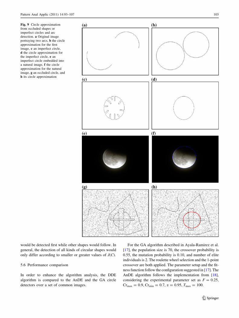
would be detected first while other shapes would follow. In
general, the detection of all kinds of circular shapes would
only differ according to smaller or greater values of J(C).
5.6 Performance comparison
In order to enhance the algorithm analysis, the DDE
algorithm is compared to the AnDE and the GA circle
detectors over a set of common images.
For the GA algorithm described in Ayala-Ramirez et al.
[17], the population size is 70, the crossover probability is
0.55, the mutation probability is 0.10, and number of elite
individuals is 2. The roulette wheel selection and the 1-point
crossover are both applied. The parameter setup and the fit-
ness function follow the configuration suggested in [17]. The
AnDE algorithm follows the implementation from [18],
considering the experimental parameter set as F = 0.25,
Crmax = 0.9, Crmin = 0.7, a = 0.95, Tmax = 100.
Fig. 9 Circle approximation
from occluded shapes or
imperfect circles and arc
detection. a Original image
portraying two arcs, b the circle
approximation for the first
image, c an imperfect circle,
d the circle approximation for
the imperfect circle, e an
imperfect circle embedded into
a natural image, f the circle
approximation for the natural
image, g an occluded circle, and
h its circle approximation
Pattern Anal Applic (2011) 14:93–107 103
123
Real-life images rarely contain perfectly shaped circles.
In order to test accuracy, the results are compared to a
ground-truth circle, which is manually detected from the
original edge-map. The parameters (xtrue, ytrue, rtrue) of such
testing circle are computed using the (7)–(10) for three
circumference points from the manually detected circle. If
the center and the radius of such circle are successfully
found by the algorithm by defining (xD, yD) and rD, then an
error score can be defined as follows:
Es = gðjxtrue � xDj þ jytrue � yDjÞ þ l rtrue � rDj j ð14Þ
The first term represents the shift of the centre of the
detected circle, as it is compared to the benchmark circle.
The second term accounts for the difference between their
radii. g and l are two weights associated to each term in
(14). They are chosen accordingly to agree the required
accuracy as g = 0.05 and l = 0.1. This particular choice
of parameters ensures that the radii difference would be
strongly weighted in comparison to the difference of center
positions between the manually detected and the machine-
detected circles.
In case the value averaged error score (Es) is less than 1,
the algorithm gets a success, otherwise it has failed in
detecting the edge-circle. Notice that for g = 0.05 and
l = 0.1, it yields Es \ 1, which accounts for a maximal
tolerated difference on radius length of 10 pixels, whereas
the maximum mismatch for the centre location can be up to
20 pixels. In general, the success rate (SR) can thus be
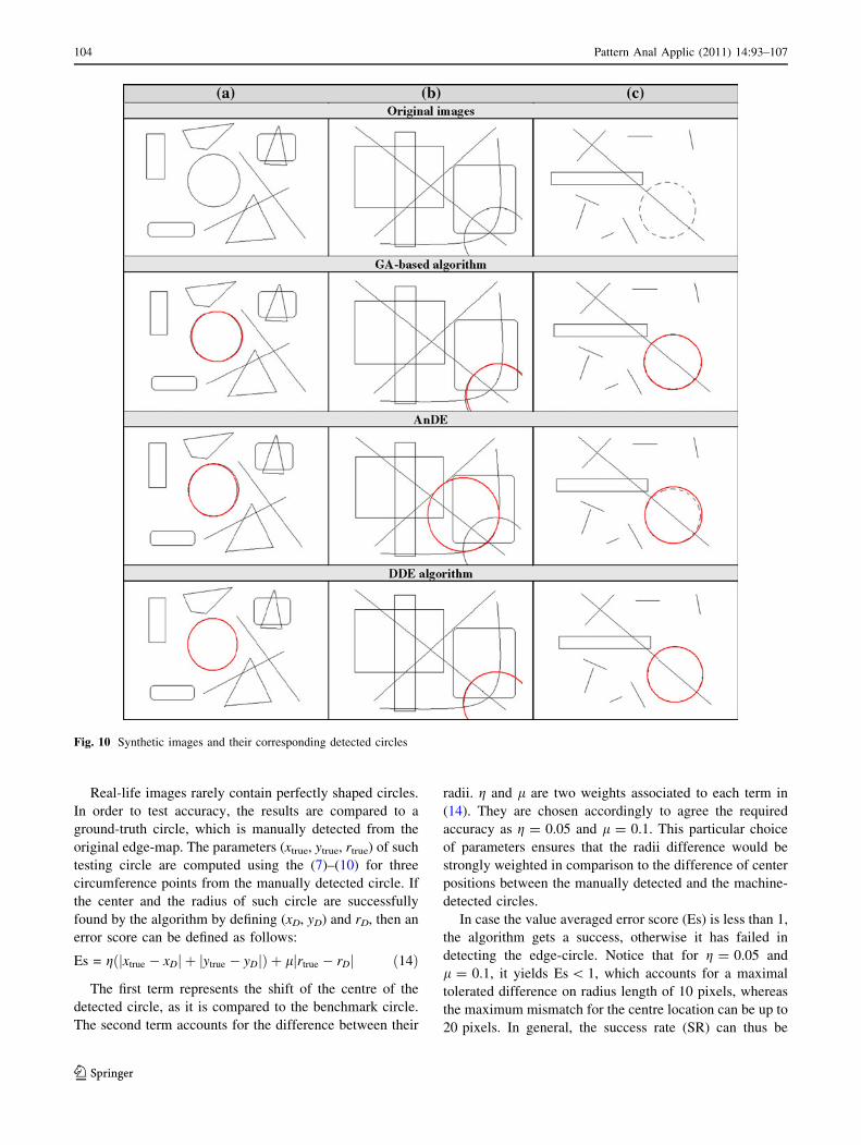
Fig. 10 Synthetic images and their corresponding detected circles
104 Pattern Anal Applic (2011) 14:93–107
123

defined as the percentage of reaching success after a certain
number of trials.
Figure 10 shows three synthetic images and the results
obtained by the GA-based algorithm [17], the AnDE [18],
and the proposed approach. Figure 11 presents the same
experimental results considering real-life images. The
results are averaged over 35 independent runs for each
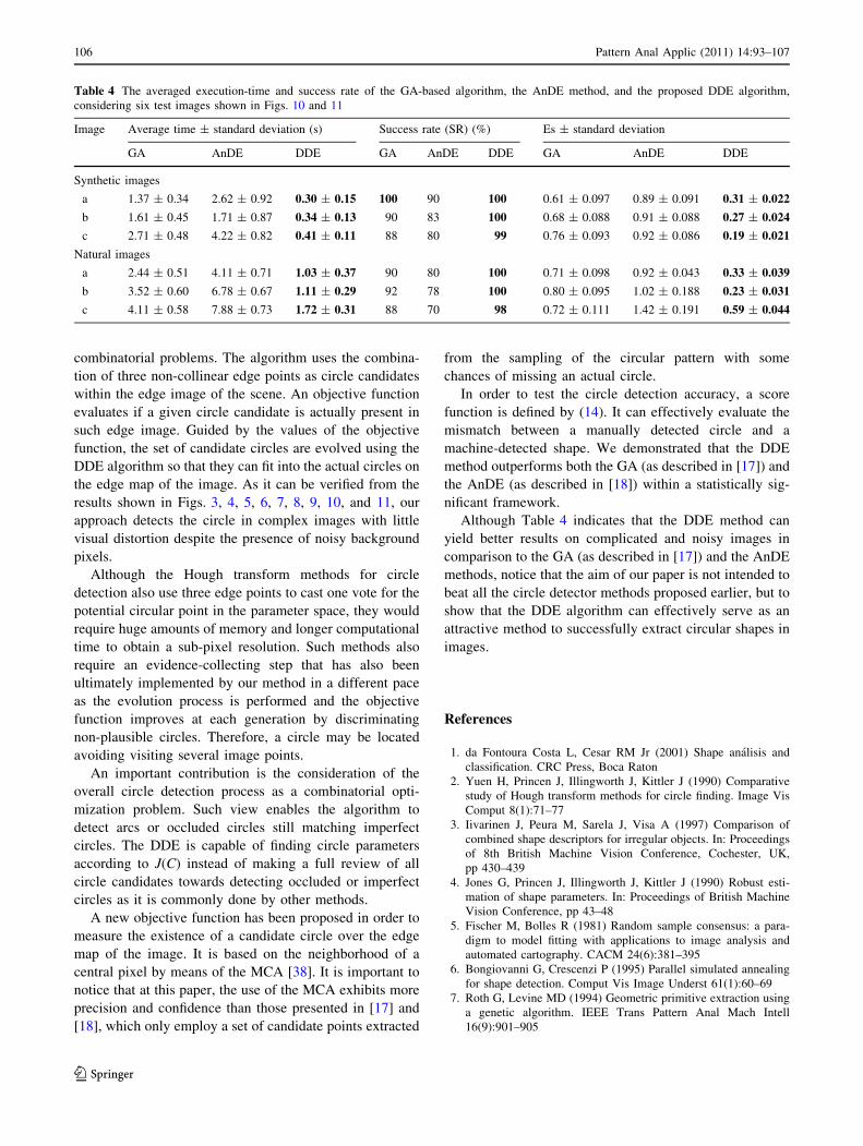
algorithm. Table 4 shows the averaged execution time, the
success rate in percentage, and the Es following Equation
(14) for all three algorithms over six test images shown in
Figs. 10 and 11. The best results are bold-cased in Table 4.
A close inspection reveals that the proposed method is able
to achieve the highest success rate and the smallest error,
still requiring less computational time for most cases.
6 Conclusions
This work has presented an algorithm for the automatic
detection of circular shapes from complicated and noisy
images with no consideration of the conventional Hough
transform principles. The proposed method is based on the
DDE algorithm which in turn has demonstrated relevant
improvements in comparison to the original DE for solving
Fig. 11 Natural images and their detected circles used by the algorithm comparison
Pattern Anal Applic (2011) 14:93–107 105
123
combinatorial problems. The algorithm uses the combina-
tion of three non-collinear edge points as circle candidates
within the edge image of the scene. An objective function
evaluates if a given circle candidate is actually present in
such edge image. Guided by the values of the objective
function, the set of candidate circles are evolved using the
DDE algorithm so that they can fit into the actual circles on
the edge map of the image. As it can be verified from the
results shown in Figs. 3, 4, 5, 6, 7, 8, 9, 10, and 11, our
approach detects the circle in complex images with little
visual distortion despite the presence of noisy background
pixels.
Although the Hough transform methods for circle
detection also use three edge points to cast one vote for the
potential circular point in the parameter space, they would
require huge amounts of memory and longer computational
time to obtain a sub-pixel resolution. Such methods also
require an evidence-collecting step that has also been
ultimately implemented by our method in a different pace
as the evolution process is performed and the objective
function improves at each generation by discriminating
non-plausible circles. Therefore, a circle may be located
avoiding visiting several image points.
An important contribution is the consideration of the
overall circle detection process as a combinatorial opti-
mization problem. Such view enables the algorithm to
detect arcs or occluded circles still matching imperfect
circles. The DDE is capable of finding circle parameters
according to J(C) instead of making a full review of all
circle candidates towards detecting occluded or imperfect
circles as it is commonly done by other methods.
A new objective function has been proposed in order to
measure the existence of a candidate circle over the edge
map of the image. It is based on the neighborhood of a
central pixel by means of the MCA [38]. It is important to
notice that at this paper, the use of the MCA exhibits more
precision and confidence than those presented in [17] and
[18], which only employ a set of candidate points extracted
from the sampling of the circular pattern with some
chances of missing an actual circle.
In order to test the circle detection accuracy, a score
function is defined by (14). It can effectively evaluate the
mismatch between a manually detected circle and a
machine-detected shape. We demonstrated that the DDE
method outperforms both the GA (as described in [17]) and
the AnDE (as described in [18]) within a statistically sig-
nificant framework.
Although Table 4 indicates that the DDE method can
yield better results on complicated and noisy images in
comparison to the GA (as described in [17]) and the AnDE
methods, notice that the aim of our paper is not intended to
beat all the circle detector methods proposed earlier, but to
show that the DDE algorithm can effectively serve as an
attractive method to successfully extract circular shapes in
images.
References
1. da Fontoura Costa L, Cesar RM Jr (2001) Shape analisis and
classification. CRC Press, Boca Raton
2. Yuen H, Princen J, Illingworth J, Kittler J (1990) Comparative
study of Hough transform methods for circle finding. Image Vis
Comput 8(1):71–77
3. Iivarinen J, Peura M, Sarela J, Visa A (1997) Comparison of
combined shape descriptors for irregular objects. In: Proceedings
of 8th British Machine Vision Conference, Cochester, UK,
pp 430–439
4. Jones G, Princen J, Illingworth J, Kittler J (1990) Robust esti-
mation of shape parameters. In: Proceedings of British Machine
Vision Conference, pp 43–48
5. Fischer M, Bolles R (1981) Random sample consensus: a para-
digm to model fitting with applications to image analysis and
automated cartography. CACM 24(6):381–395
6. Bongiovanni G, Crescenzi P (1995) Parallel simulated annealing
for shape detection. Comput Vis Image Underst 61(1):60–69
7. Roth G, Levine MD (1994) Geometric primitive extraction using
a genetic algorithm. IEEE Trans Pattern Anal Mach Intell
16(9):901–905
Table 4 The averaged execution-time and success rate of the GA-based algorithm, the AnDE method, and the proposed DDE algorithm,
considering six test images shown in Figs. 10 and 11
Image Average time ± standard deviation (s) Success rate (SR) (%) Es ± standard deviation
GA AnDE DDE GA AnDE DDE GA AnDE DDE
Synthetic images
a 1.37 ± 0.34 2.62 ± 0.92 0.30 ± 0.15 100 90 100 0.61 ± 0.097 0.89 ± 0.091 0.31 ± 0.022
b 1.61 ± 0.45 1.71 ± 0.87 0.34 ± 0.13 90 83 100 0.68 ± 0.088 0.91 ± 0.088 0.27 ± 0.024
c 2.71 ± 0.48 4.22 ± 0.82 0.41 ± 0.11 88 80 99 0.76 ± 0.093 0.92 ± 0.086 0.19 ± 0.021
Natural images
a 2.44 ± 0.51 4.11 ± 0.71 1.03 ± 0.37 90 80 100 0.71 ± 0.098 0.92 ± 0.043 0.33 ± 0.039
b 3.52 ± 0.60 6.78 ± 0.67 1.11 ± 0.29 92 78 100 0.80 ± 0.095 1.02 ± 0.188 0.23 ± 0.031
c 4.11 ± 0.58 7.88 ± 0.73 1.72 ± 0.31 88 70 98 0.72 ± 0.111 1.42 ± 0.191 0.59 ± 0.044
106 Pattern Anal Applic (2011) 14:93–107
123

8. Peura M, Iivarinen J (1997) Efficiency of simple shape descrip-
tors. In: Arcelli C, Cordella LP, di Baja GS (eds) Advances in
visual form analysis. World Scientific, Singapore, pp 443–451
9. Muammar H, Nixon M (1989) Approaches to extending the
Hough transform. In: Proceedings of International conference on
acoustics, speech and signal processing ICASSP_89, vol 3.
pp 1556–1559
10. Atherton TJ, Kerbyson DJ (1993) Using phase to represent radius
in the coherent circle Hough transform. In: Proceedings on IEE
colloquium on the Hough transform. IEE, London
11. Shaked D, Yaron O, Kiryati N (1996) Deriving stopping rules for
the probabilistic Hough transform by sequential analysis. Comput
Vis Image Underst 63:512–526
12. Xu L, Oja E, Kultanen P (1990) A new curve detection method:
randomized Hough transform (RHT). Pattern Recognit 11(5):
331–338
13. Han JH, Koczy LT, Poston T (1993) Fuzzy Hough transform. In:
Proceedings of 2nd International Conference on Fuzzy Systems,
vol 2, pp 803–808
14. Becker J, Grousson S, Coltuc D (2002) From Hough transforms
to integral transforms. In: Proceedings of International Geosci-
ence and Remote Sensing Symposium, 2002 IGARSS_02, vol. 3,
pp 1444–1446
15. Lutton E, Martinez P (1994) A genetic algorithm for the detec-
tion 2-D geometric primitives on images. In: Proceedings of the
12th International conference on pattern recognition, vol 1,
pp 526–528
16. Yao J, Kharma N, Grogono P (2004) Fast robust GA-based
ellipse detection. In: Proceedings of 17th International Confer-
ence on pattern recognition ICPR-04, vol 2, Cambridge, UK,
pp 859–862
17. Ayala-Ramirez V, Garcia-Capulin CH, Perez-Garcia A, Sanchez-
Yanez RE (2006) Circle detection on images using genetic
algorithms. Pattern Recognit Lett 27:652–657
18. Swagatam D, Sambarta D, Arijit B, Ajith A (2008) Automatic
circle detection on images with annealed differential evolution.
In: Proceedings of 8th International conference on hybrid intel-
ligent systems 2008, pp 684–689
19. Rosin PL, Nyongesa HO (2000) Combining evolutionary, con-
nectionist, and fuzzy classification algorithms for shape analysis.
In: Cagnoni S et al (eds) Proceedings of EvoIASP, real-world
applications of evolutionary computing, pp 87–96
20. Rosin PL (1994) Further five point fit ellipse fitting. In: Pro-
ceedings of 8th British Machine Vision Conference, Cochester,
UK, pp 290–299
21. Zhang X, Rosin PL (2003) Superellipse fitting to partial data.
Pattern Recognit Lett 36:743–752
22. Storn R, Price K (1995) Differential evolution—a simple and
efficient adaptive scheme for global optimization over continuous
spaces. Technical Rep. No. TR-95-012, International Computer
Science Institute, Berkley
23. Reddy JM, Kumar ND (2007) Multiobjective differential evolu-
tion with application to reservoir system optimization. J Comput
Civil Eng 21(2):136–146
24. Babu B, Munawar S (2007) Differential evolution strategies for
optimal design of shell-and-tube heat exchangers. Chem Eng Sci
62(14):3720–3739
25. Mayer D, Kinghorn B, Archer A (2005) Differential evolution—
an easy and efficient evolutionary algorithm for model optimi-
zation. Agric Syst 83:315–328
26. Kannan S, Mary Raja Slochanal S, Padhy N (2003) Application and
comparison of metaheuristic techniques to generation expansion
planning problem. IEEE Trans Power Syst 20(1):466–475
27. Chiou J, Chang C, Su C (2005) Variable scaling hybrid differ-
ential evolution for solving network reconfiguration of distribu-
tion systems. IEEE Trans Power Syst 20(2):668–674
28. Chiou J, Chang C, Su C (2004) Ant direct hybrid differential
evolution for solving large capacitor placement problems. IEEE
Trans Power Syst 19(4):1794–1800
29. Ursem R, Vadstrup P (2003) Parameter identification of induction
motors using differential evolution. In: Proceedings of the 2003
congress on evolutionary computation (CEC’03), vol. 2. Can-
berra, Australia, pp 790–796
30. Babu B, Angira R, Chakole G, Syed Mubeen J (2003) Optimal
design of gas transmission network using differential evolution.
In: Proceedings of the second international conference on com-
putational intelligence, robotics, and autonomous systems
(CIRAS-2003), Singapore
31. Zelinka I, Chen G, Celikovsky S (2008) Chaos sythesis by means
of evolutionary algorithms. Int J Bifurcat Chaos 4:911–942
32. Onwubolu G, Davendra D (2009) Differential evolution: a
handbook for global permutation-based combinatorial optimiza-
tion. Springer, Heidelberg
33. Yuan X, Su A, Nie H, Yuan Y, Wang L (2009) Application of
enhanced discrete differential evolution approach to unit com-
mitment problem. Energy Convers Manag 50(9):2449–2456
34. Wang L, Pan Q-K, Suganthan PN, Wang W-H, Wang Y-M
(2010) A novel hybrid discrete differential evolution algorithm
for blocking flow shop scheduling problems. Comput Oper Res
37(3):509–520
35. Tasgetiren MF, Pan Q-K, Liang Y-C (2009) A discrete differ-
ential evolution algorithm for the single machine total weighted
tardiness problem with sequence dependent setup times. Comput
Oper Res 36(6):1900–1915
36. Tasgetiren MF, Suganthan PN, Pan Q-K (2010) An ensemble of
discrete differential evolution algorithms for solving the gen-
eralized traveling salesman problem. Appl Math Comput 215(9):
3356–3368
37. Onwubolu G, Davendra D (2006) Scheduling flow shops using
differential evolution algorithm. Eur J Oper Res 171:674–679
38. Lichtblau D (2009) Relative position index approach. In:
Davendra D, Onwubolu G (eds) Differential evolution: a hand-
book for global permutation-based combinatorial optimization.
Springer, Heidelberg, pp 81–120
39. Tasgetiren F, Chen A, Gencyilmaz G, Gattoufi S (2009) Smallest
position value approach. In: Davendra D, Onwubolu G (eds)
Differential evolution: a handbook for global permutation-based
combinatorial optimization. Springer, Heidelberg, pp 81–120
40. Tasgetiren F, Liang Y, Pan Q, Suganthan P (2009) Discrete/
binary approach. In: Davendra D, Onwubolu G (eds) Differential
evolution: a handbook for global permutation-based combinato-
rial optimization. Springer, Heidelberg, pp 81–120
41. Zelinka I (2009) Discrete set handling. In: Davendra D,
Onwubolu G (eds) Differential evolution: a handbook for
global permutation-based combinatorial optimization. Springer,
Heidelberg, pp 81–120
42. Bresenham JE (1987) A linear algorithm for incremental digital
display of circular arcs. Commun ACM 20:100–106
43. Davendra D, Onwubolu G (2009) Forward backward transfor-
mation. In: Davendra D, Onwubolu G (eds) Differential evolu-
tion: a handbook for global permutation-based combinatorial
optimization. Springer, Heidelberg, pp 37–78
44. Franco G, Betti R, Lus H (2004) Identification of structural systems
using an evolutionary strategy. Eng Mech 130(10):1125–1139
45. Koziel S, Michalewicz Z (1999) Evolutionary algorithms, ho-
momorphous mappings, and constrained parameter optimization.
Evol Comput 7(1):19–44
46. Van Aken JR (1984) An efficient ellipse drawing algorithm.
CG&A 4(9):24–35
47. Yuen S, Ma C (2000) Genetic algorithm with competitive image
labelling and least square. Pattern Recognit 33:1949–1966
Pattern Anal Applic (2011) 14:93–107 107
123