Contactors and Starters-IEC (July 2021)
62
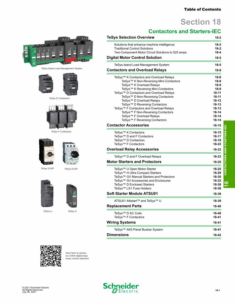
© 2021 Schneider Electric All Rights Reserved July 30, 2021 18-1 TeSys D Contactors TeSys F Contactors TeSys GV3P TeSys GV2P TeSys U Scan here to access our online digital easy motor control selectors TeSys H TeSys island Load Management System Table of Contents Section 18 Contactors and Starters-IEC TeSys Selection Overview 18-2 Solutions that enhance machine intelligence 18-2 Traditional Control Solutions 18-2 Two-Component Motor Circuit Solutions to 520 amps 18-4 Digital Motor Control Solution 18-5 TeSys island Load Management System 18-5 Contactors and Overload Relays 18-8 TeSys™ K Contactors and Overload Relays 18-8 TeSys™ K Non-Reversing Mini-Contactors 18-8 TeSys™ K Overload Relays 18-9 TeSys™ K Reversing Mini-Contactors 18-9 TeSys™ D Contactors and Overload Relays 18-11 TeSys™ D Non-Reversing Contactors 18-11 TeSys™ D Overload Relays 18-12 TeSys™ D Reversing Contactors 18-13 TeSys™ F Contactors and Overload Relays 18-13 TeSys™ F Non-Reversing Contactors 18-14 TeSys™ F Overload Relays 18-14 TeSys™ F Reversing Contactors 18-14 Contactor Accessories 18-15 TeSys™ K Contactors 18-15 TeSys™ D and F Contactors 18-17 TeSys™ D Contactors 18-19 TeSys™ F Contactors 18-22 Overload Relay Accessories 18-23 TeSys™ D and F Overload Relays 18-23 Motor Starters and Protectors 18-25 TeSys™ U Open Motor Starter 18-25 TeSys™ H Ultra Compact Starters 18-29 TeSys™ GV Manual Starters and Protectors 18-30 TeSys™ GV Accessories and Enclosures 18-32 TeSys™ D Enclosed Starters 18-36 TeSys™ LS1 Fuse Holders 18-38 Soft Starter Module ATSU01 18-39 ATSU01 Altistart™ and TeSys™ U 18-39 Replacement Parts 18-40 TeSys™ D AC Coils 18-40 TeSys™ F Contactors 18-41 Wiring Systems 18-41 TeSys™ AK5 Panel Busbar System 18-41 Dimensions 18-42 18 CONTACTORS AND STARTERS-IEC
-
Upload
khangminh22 -
Category
Documents
-
view
0 -
download
0
Transcript of Contactors and Starters-IEC (July 2021)
© 2021 Schneider Electric All Rights ReservedJuly 30, 2021
18-1
TeSys D Contactors
TeSys F Contactors
TeSys GV3P TeSys GV2P
TeSys U
Scan here to accessour online digital easymotor control selectors
TeSys H
TeSys island Load Management System
Table of Contents
Section 18Contactors and Starters-IEC
TeSys Selection Overview 18-2
Solutions that enhance machine intelligence 18-2Traditional Control Solutions 18-2Two-Component Motor Circuit Solutions to 520 amps 18-4
Digital Motor Control Solution 18-5
TeSys island Load Management System 18-5
Contactors and Overload Relays 18-8
TeSys™ K Contactors and Overload Relays 18-8TeSys™ K Non-Reversing Mini-Contactors 18-8TeSys™ K Overload Relays 18-9TeSys™ K Reversing Mini-Contactors 18-9
TeSys™ D Contactors and Overload Relays 18-11TeSys™ D Non-Reversing Contactors 18-11TeSys™ D Overload Relays 18-12TeSys™ D Reversing Contactors 18-13
TeSys™ F Contactors and Overload Relays 18-13TeSys™ F Non-Reversing Contactors 18-14TeSys™ F Overload Relays 18-14TeSys™ F Reversing Contactors 18-14
Contactor Accessories 18-15
TeSys™ K Contactors 18-15TeSys™ D and F Contactors 18-17TeSys™ D Contactors 18-19TeSys™ F Contactors 18-22
Overload Relay Accessories 18-23
TeSys™ D and F Overload Relays 18-23
Motor Starters and Protectors 18-25
TeSys™ U Open Motor Starter 18-25TeSys™ H Ultra Compact Starters 18-29TeSys™ GV Manual Starters and Protectors 18-30TeSys™ GVAccessories and Enclosures 18-32TeSys™ D Enclosed Starters 18-36TeSys™ LS1 Fuse Holders 18-38
Soft Starter Module ATSU01 18-39
ATSU01 Altistart™ and TeSys™ U 18-39
Replacement Parts 18-40
TeSys™ D AC Coils 18-40TeSys™ F Contactors 18-41
Wiring Systems 18-41
TeSys™ AK5 Panel Busbar System 18-41
Dimensions 18-42
18CONTA
CTORSANDSTA
RTERS-IEC

18-2 © 2021 Schneider Electric All Rights Reserved
July 30, 2021
TeSys Selection Overview Solutions that enhance machineintelligence
www.se.com/usRefer to CatalogMKTED210011EN
TeSys Control SolutionsTeSys offers solutions for a variety of common control applications, including small tolarge loads, motor and non-motor loads, in various forms to meet customers specificneeds. Basic solutions offer traditional approaches that meet compact, cost-effective,and large HP applications. TeSys also equips OEMs and System Integrators withEcoStruxure Machine connected product solutions that are IoT ready offers to helpenhance the intelligence of machinery and equipment, helping to recognize and addresspotential issues before stoppage and decrease unplanned downtime.
Traditional ControlTable 18.1: Solutions that enhance machine intelligence
Solution 1 — TeSys island asgroup motor
Solution 2 — TeSys island withindividual protection
Solution 3 — TeSys U(Type E self-protected)using Multi-function tripunit & communicationmodule or using pre-tripalarm function module
Solution 4 — TeSys Toverload relay
Solution 5 — TeSysGV4PB, GV5PB, GV6PBwith SDx Module
Best PracticeScenario
Ideal for panels with multiple loads.Single bus coupler serves asconnection to PLC, manages logicand configuration for starters.
Ideal for panels with multiple loads.Single bus coupler serves asconnection to PLC, manages logicand configuration for starters.
Ideal for panels with oneor two motors. Eachstarter communicatesdirectly to PLC.
Ideal for larger HP. Eachoverload relaycommunicates directly toPLC.
Ideal for adding intelligenceusing a simple NO/NCpre-trip alarm contact—Use of PLC to receive/interpret data not required.
BenefitsSee load, device and systemperformance. Set alarms to anticipatemaintenance and optimizeperformance.
See load, device and systemperformance. Set alarms to anticipatemaintenance and optimizeperformance.
See load performance. Setalarms to anticipatemaintenance and optimizeperformance.
See load performance. Setalarms to anticipatemaintenance and optimizeperformance.
Pre-trip alarm NO/NCcontact alerts prior to trip,enabling proactive actionsto minimize downtime oralert operators
Circuit Protection Circuit breaker or fuse protectiongroup Circuit breaker or fuse TeSys U (applied as Type E
self protected), usingadvanced trip unit/functionmodules
Breaker or fuse GV4PB, GV5PB, GV6PB
Motor Control TeSys island load managementsystem with or without TeSys GV
TeSys island load managementsystem
TeSys D or F contactors TeSys D or FMotor OverloadProtection TeSys Toverload relay (included in GV*PB)
Load Types Motor, resistive/non-inductive,isolation
Motor, resistive/non-inductive,isolation Motor loads only Motor loads only Motor loads only
Max HP 480V 40 HP 40 HP 20 HP 500 HP (up to 810 amps) 450 HP (up to 520 amps)SCCR basic 5 kA up to high 50 kA (with GV) high, to 100 kA High, to 65 kA Depends on configuration Depends on configuration
Available dataDevice status/performance Loadperformance including alarmsVoltage, Energy & Power
Device status/performance Loadperformance including alarmsVoltage, Energy & Power
Load performance includingalarms
Load performance includingalarms Voltage & Power
Pre-trip alarm (via NO/NCcontact)
Communication Ethernet IP, Modbus TCP, Profinet,Profibus
Ethernet IP, Modbus TCP, Profinet,Profibus
Modbus™, CANopen,DeviceNet™, Profibus™
Modbus™, CANopen,DeviceNet™, Profibus™,Ethernet/IP, and Modbus/TCP
None
18CONTA
CTORSANDSTA
RTERS-IE
C

© 2021 Schneider Electric All Rights ReservedJuly 30, 2021
18-3
www.se.com/us
Traditional Control Solutions TeSys Selection OverviewRefer to Catalog MKTED210011EN
Table 18.2: Basic — Traditional motor control solutionSolution 1 — Two component solution(TeSys GV + D)
Solution 2 — Singlecomponentsolution
Solution 3 — GroupMotor solution Solution 5 — Three
componentsolution (Breaker/fuse, contactor &overload relay)
Solution 6 — TypeD solution (Motorcircuit protector,contactor &overload relay)
Solution 7 — Non-motor loadsolution (Breaker/fuse +contactor)Type F — up to 65
amps
Motor ProtectiveCircuit Breakers +contactor - up to520 amps
Type E — up to 32amps up to 65 amps
BestPracticeScenario
Most cost effective, high SCCR solution
Most compact, alsoideal for criticaluptime applcations(resetable after ashort-circuit with nocomponentreplacement), highSCCR solution
Few components,480V delta rated
3-componentsolution, ideal forhigher HPs or highSCCR
ideal for pumpingapplications,includes adjustablemotor in rushsensitivity
ideal for non-motor loads
BenefitsSimple, 2-componentsolution, costeffective, fast powerwiring using bus bars
Simple, 2-componentsolution, costeffective for largerHP motors
Single componentsolution, Type 2rated (minimizedowntime after short-circuit)
cost effectivesolution ideal forpanels with manymotor loads (singlebreaker for multiplestarters)
basic solution, idealfor 480V deltaapplications,resetable afterbreaker trip
adjustable motorinrush sensitivity,ideal for pumpingapplications
ideal for non-motor loads
CircuitProtection
TeSys GV2P, GV3P(applied as Type Fwith contactor)
TeSys GV4PB,GV5PB, GV6PB (UL489)
TeSys U, with basictrip unit
PowerPact or Multi9(UL 489) or fuses
PowerPact or Multi9(UL 489) or TeSysDF, LS1 fuseholder,GS disconnect withfuses
TeSys BV4 (UL 489)PowerPact or Mulit9 (UL 489) orTeSys DF, LS1 fuseholder, GSdisconnect with fuses
MotorControl Tesys D TeSys D or F TeSys D TeSys D or F TeSys D TeSys D or F
MotorOverloadProtection
(included in GV) (included in GV) TeSys GV2ME LR thermal or LR9electronic
LR thermal or LR9electronic —
Load Types Motor loads only Motor loads only Motor loads only Motor loads only Motor loads only Motor loads only Resistive/non-inductive, isolation
18CONTA
CTORSANDSTA
RTERS-IEC

18-4 © 2021 Schneider Electric All Rights Reserved
July 30, 2021
TeSys Selection Overview Two-Component Motor Circuit Solutions to520 amps
www.se.com/usRefer to CatalogMKTED210011EN
Two-Component Motor Circuit Solutions to 520 AmpsSimplify design, panel space and installation with TeSys high SCCR solution that useonly two components that make up an entire branch circuit up to 520 amps. These two-component solutions are UL compliant using either a Type F combination motorcontroller rating or a UL 489 rating. For additional solutions and ratings, see MotorControl Solutions for North America data bulletin 8536DB0901.
GV2P +LC1D GV3P + LC1D GV4PB + LC1D GV5PB + LC1F GV6PB + LC1F
Table 18.3: Quick selection table for TeSys 2–component motor circuit solutions200 V 3P 230 V 3P 460 V 3P
GV Ref Overload DialRange (A)
ContactorRefContactor
Ref[1]
Pre-assembled
RefContactorRef[1]
SCCR 480Y asapplied withspecifiedprotection
HP FLA[2] HP FLA[2] HP FLA[2]
— — — — 1/2 1.1 GV2P06 1 to 1.6 LC1D09 GV2P06KD09 100 kA[3]— — — — 3/4 1.6 GV2P06 1 to 1.6 LC1D09 GV2P06KD09 100 kA[3]1/2 2.5 1/2 2.2 1 2.1 GV2P07 1.6 to 2.5 LC1D09 GV2P07KD09 100 kA[3]— — — — 11/2 3 GV2P08 2.5 to 4 LC1D09 GV2P08KD09 100 kA[3]3/4 3.7 3/4 3.2 2 3.4 GV2P08 2.5 to 4 LC1D09 GV2P08KD09 100 kA[3]1 4.6 1 4.2 3 4.8 GV2P10 4 to 6.3 LC1D09 GV2P10KD09 100 kA[3]— — 11/2 6 —— —— GV2P10 4 to 6.3 LC1D09 GV2P10KD09 100 kA[3]1 1/2 6.9 2 6.8 — — GV2P14 6 to 10 LC1D12 GV2P14KD09 100 kA[3]2 7.8 — — 5 7.6 GV2P14 6 to 10 LC1D12 GV2P14KD09 100 kA[3]— — 3 9.6 — — GV2P16 9 to 14 LC1D12 GV2P16KD25 50 kA[4]3 11 — — 7 1/2 11 GV2P16 9 to 14 LC1D18 GV2P16KD25 50 kA[4]— — — — 10 14 GV2P16 9 to 14 LC1D18 GV2P16KD25 50 kA[4]5 17.5 5 15.2 — — GV2P20 13 to 18 LC1D18 GV2P20KD25 50 kA[4]— — 7 1/2 22 15 21 GV2P21 17 to 23 LC1D25 GV2P21KD25 50 kA[4]
7 1/2 25.3 — — — — GV2P22 20 to 25 LC1D25 GV2P22KD25 50 kA[4]— — 10 28 20 27 GV3P32 23 to 32 LC1D32 — 65 kA[5]10 32.2 — — 25 34 GV3P40 30 to 40 LC1D40A — 65 kA[5]— — 15 42 30 40 GV3P50 37 to 50 LC1D50A — 65 kA[5]15 48 20 54 40 52 GV3P65 48 to 65 LC1D65A — 65 kA[5]20 62.1 25 68 50 65 GV4PB115S 65 to 115 LC1D80 — 65 kA25 78.2 30 80 60 77 GV4PB115S 65 to 115 LC1D80 — 65 kA30 92 — — — — GV4PB115S 65 to 115 LC1D115 — 65 kA— — 40 104 75 96 GV5PB150S 58 to 130 LC1D115 — 65 kA40 120 — — — — GV5PB150S 58 to 130 LC1D150 — 65 kA— — 50 130 100 124 GV5PB250S 114 to 217 LC1D150 — 65 kA50 150 60 154 125 156 GV5PB250S 114 to 217 LC1D185 — 65 kA[6]60 177 75 192 150 180 GV5PB250S 114 to 217 LC1F265 — 10 kA[7]75 221 100 248 200 240 GV6PB400S 190 to 348 LC1F330 — 10 kA[7]100 285 125 312 250 302 GV6PB400S 190 to 348 LC1F400 — 18 kA125 359 150 360 300 361 GV6PB600S 312 to 520 LC1F500 — 18 kA150 414 200 480 400 477 GV6PB600S 312 to 520 LC1F500 — 18 kA200 552 — — 450 515 GV6PB600S 312 to 520 LC1F630 — 30 kA
18CONTA
CTORSANDSTA
RTERS-IE
C
[1] Add coil suffix to complete reference part number (See Table 18.24 TeSys D Coil Voltage Codes , page 18-11 for LC1D and Table 18.30 TeSys F Coil Voltage Codes, page 18-14 for LC1F).For example, an LC1D09G7 includes a 120 Vac coil.
[2] Motor Full Load Amp Sizes are based on NEC Table 430.250.[3] Requires use of GV1G09 or GV2GH7 line spacer for Type F rating. SCCR is 100 kA at 480Y with or without use of GV2G busbar links.[4] Requires use of GV1G09 or GV2Gh7 line spacer for Type F rating. SCCR is 42 kA at 480Y when using GV2G busbar links.[5] Requires use of GV3G66 line spacer and GVAM11 short-circuit signaling contact for Type F rating.[6] Max wire size of 3/0 AWG for 65kA 480 V SCCR.[7] 100kA SCCR with fuses. See Motor Control Solutions for North America data bulletin 8536DB0901 for more information.

© 2021 Schneider Electric All Rights ReservedJuly 30, 2021
18-5
www.se.com/us
TeSys island Load Management System Digital Motor Control SolutionRefer to Catalog MKTED210011EN
Island ConceptTeSys island is an innovative digital load management solution—providing data forhigher machine efficiency and ease of servicing, and allowing faster time to market.TeSys island is a modular, multifunctional system providing integrated functions inside anautomation architecture, primarily for the direct control and management of low-voltageloads. TeSys island can switch, help protect, and manage motors and other electricalloads up to 40 hp, 80 A installed in an electrical control Panel.This system is designed around the concept of TeSys™ avatars.These avatars:• are the functional object representing a logical function of the physical module withpre-defined logic
• determine the configuration of the island.The logical aspects of the island are managed with software tools, covering all phases ofproduct and application lifecycle: design, engineering, commissioning, operation, andmaintenance.
1 Bus Coupler 5 Power interface module2 Analog I/O module 6 Standard Starter3 Digital I/O module 7 SIL Starter4 Voltage interface module 9 SIL interface module
The physical island consists of a set of devices installed on a single DIN rail controllingloads, monitoring data, diagnostics information and connected together with a ribboncable providing the internal communication between modules.The external communication with the automation environment is made via a singlecoupler module, and the island is seen as a single node on the network. The othermodules include starters, power interface modules, analog and digital I/O modules,voltage interface modules, and SIL interface modules, covering a wide range ofoperational functions.
18CONTA
CTORSANDSTA
RTERS-IEC

18-6 © 2021 Schneider Electric All Rights Reserved
July 30, 2021
Digital Motor Control Solution TeSys island Load Management System
www.se.com/us
Refer to Catalog LVCATISL
Product ReferencesThe TeSys island load management system consists of a bus coupler along with otherstarters and modules as needed to build an “island” of load management, monitoring &control functions. It is recommended to use the online EcoStruxure Motor ControlConfigurator to ensure proper application and sizing.
Scan here to access our onlineEcoStruxure Motor Control Configurator
TPRBCEIP
TPRST009
Table 18.4: Bus CouplersDesignation Upstream PLC
protocolService Portprotocol Product Reference Weight (kg)
TeSys island BusCoupler
EtherNet/IP–ModbusTCP Ethernet TCP/IP TPRBCEIP 0.204
PROFINET Ethernet TCP/IP TPRBCPFN 0.204PROFIBUS Ethernet TCP/IP TPRBCPFB 0.204
Table 18.5: 3-Pole StartersMaximum Horsepower Ratings
ProductReference
Weight(kg)
Single-Phase Three-Phase Continu-ous
CurrentRating (A)115 V 230 V 200 V 230 V 460 V 575 V
1/3 1 2 2 5 5 15 TPRST009 0.6562 3 7 1/2 7 1/2 15 20 30 TPRST025 0.7182 5 10 10 20 25 40 TPRST038 0.7185 10 20 20 40 50 80 TPRST065 1.2485 10 20 20 40 50 80 TPRST080 1.248
18CONTA
CTORSANDSTA
RTERS-IE
C

© 2021 Schneider Electric All Rights ReservedJuly 30, 2021
18-7
www.se.com/us
TeSys island Load Management System Digital Motor Control SolutionRefer to Catalog LVCATISL
TPRS025
TPRSM001
TPRVM001
TPRDG4X2
Table 18.6: 3-Pole SIL StartersMaximum Horsepower Ratings
Product Reference Weight(kg)
Single-Phase Three-Phase Continu-ous
CurrentRating (A)115 V 230 V 200 V 230 V 460 V 575 V
1/3 1 2 2 5 5 15 TPRSS009 0.6562 3 7 1/2 7 1/2 15 20 30 TPRSS025 0.7182 5 10 10 20 25 40 TPRSS038 0.7185 10 20 20 40 50 80 TPRSS065 1.2485 10 20 20 40 50 80 TPRSS080 1.248
Table 18.7: 3-Pole PIM StartersMaximum Horsepower Ratings
ProductRefer-ence
Weight(kg)
Single-Phase Three-Phase Continu-ous
CurrentRating (A)115 V 230 V 200 V 230 V 460 V 575 V
1/3 1 2 2 5 5 15 TPRP-M009 0.255
2 5 10 10 20 25 40 TPRP-M038 0.255
5 10 20 20 40 50 80 TPRP-M080 0.425
Table 18.8: SIL Interface ModuleDesignation Voltage (Vdc) Product Reference Weight (kg)TeSys island SIL interface module (SIM) 24 TPRSM001 0.159
Table 18.9: Voltage Interface Module (VIM)Designation Phase Voltage
(V)Frequency
(Hz) Product Reference Weight(kg)
TeSys island Voltage interface module(SIM) 1P/3P 100 to 690 50–60 TPRVM001 0.159
Table 18.10: Digital I/O ModuleDesignation Input Vdc Output A /
VdcFrequency
(Hz) Product Reference Weight(kg)
TeSys island DG—Digital 4I/2O Module 24 0.5 / 24 50–60 TPRDG4X2 0.136
Table 18.11: Analog I/O ModuleDesignation Inputs Output Product
ReferenceWeight(kg)mA dc Vdc mA dc Vdc
TeSys island—Analog 2I/2OModule
0–20 –10 to+10 0–20 –10 to
+10 TPRAN2X1 0.17240–20 0–10 4–20 0–10
18CONTA
CTORSANDSTA
RTERS-IEC

18-8 © 2021 Schneider Electric All Rights Reserved
July 30, 2021
Contactors and Overload Relays TeSys™ K Contactors and Overload Relays
www.se.com/us
Refer to CatalogMKTED210011EN
TeSys™ K Non-Reversing Mini-Contactors
LC1K09 LP4K09
Table 18.12: Mini-Contactors with AC Operating CoilsMaximum Horsepower Ratings Maximum Current (A) Continuous
CurrentRating (A)
Type ofConnection
AuxiliaryContacts
CatalogNumber [1][2]Single-Phase Three-Phase
Inductive AC3 Resistive AC1115 V 230 V 200 V 230 V 460 V 575 V N.O. N.C.
0.5 1 1.5 1.5 3 3 6 20 10 Screw-clamp 1 — LC1K0610— 1 LC1K0601
0.5 1.5 2 3 5 5 9 20 20 Screw-clamp 1 — LC1K0910— 1 LC1K0901
1 2 3 3 7.5 10 12 20 20 Screw-clamp 1 — LC1K1210— 1 LC1K1201
4-Pole Mini Contactor
1/2 1.5 2 3 5 5 9 20 20 Screw-clamp 4 — LC1K090042 2 LC1K09008
1 2 3 3 7.5 10 12 20 20 Screw-clamp 4 — LC1K120044-Pole Mechanically Interlocked Contactors
1/2 1.5 2 3 5 5 9 20 20 Screw-clamp 4 — LC2K090041 2 3 3 7.5 10 12 20 20 Screw-clamp 4 — LC2K12004
Table 18.13: Coil Voltage Codes for AC ContactorsVac 50/60 Hz 24 110 120 230/240
Code B7 F7 G7 U7
Table 18.14: Mini-Contactors with 24 Vdc Operating CoilsMaximum Horsepower Ratings Maximum Current (A) Continuous
Current Rating(A)
Type ofConnection
AuxiliaryContacts Catalog Number [2]Single-Phase Three-Phase Inductive
AC3Resistive
AC1115 V 230 V 200 V 230 V 460 V 575 V N.O. N.C.
0.5 1 1.5 1.5 3 3 6 20 10 Screw-clamp 1 — LP1K0610BD— 1 LP1K0601BD
0.5 1.5 2 3 5 5 9 20 20 Screw-clamp 1 — LP1K0910BD— 1 LP1K0901BD
1 2 3 3 7.5 10 12 20 20 Screw-clamp 1 — LP1K1210BD— 1 LP1K1201BD
4-Pole Mini Contactor
1/2 1.5 2 3 5 5 9 20 20 Screw-clamp 4 — LP1K09004BD2 2 LP1K09008BD
1 2 3 3 7.5 10 12 20 20 Screw-clamp 4 — LP1K12004BD4-Pole Mechanically Interlocked Contactors1/2 1.5 2 3 5 5 9 20 20 Screw-clamp 4 — LP2K09004BD1 2 3 3 7.5 10 12 20 20 Screw-clamp 4 — LP2K129004BD
Table 18.15: Mini-Contactors with Low-Consumption 24 Vdc Operating Coil (includes built-in transient suppression) [3]Maximum Horsepower Ratings Maximum Current (A)
Continuous CurrentRating (A)
Type ofConnection
AuxiliaryContacts Catalog Number
[2]Single-Phase Three-Phase Inductive AC3 Resistive AC1115 V 230 V 200 V 230 V 460 V 575 V N.O. N.C.
0.5 1 1.5 1.5 3 3 6 20 10 Screw-clamp 1 — LP4K0610BW3— 1 LP4K0601BW3
0.5 1.5 2 3 5 5 9 20 20 Screw-clamp 1 — LP4K0910BW3— 1 LP4K0901BW3
1 2 3 3 7.5 10 12 20 20 Screw-clamp 1 — LP4K1210BW3— 1 LP4K1201BW3
18CONTA
CTORSANDSTA
RTERS-IE
C
[1] Complete the catalog number with the coil voltage from (for example LC1K0610G7).[2] For additional terminal options and coil voltage/consumption options, see Catalog MKTED210011EN. Check with local sales office for availability.[3] 1.8 W inrush.

© 2021 Schneider Electric All Rights ReservedJuly 30, 2021
18-9
www.se.com/us
TeSys™ K Contactors and Overload Relays Contactors and Overload RelaysRefer to Catalog MKTED210011EN
TeSys™ K Overload Relays
LR2K0316
Table 18.16: Overload Relays for 3-Pole Contactors with Screw-Clamp TerminalsCurrent Setting Range (A) Catalog Number
0.11 to 0.16 LR2K0301
LR2K overload relays:
• AC or DC protection
• Ambient compensated bimetallic
• Class 10
• Single phase sensitivity
• Manual or auto reset• Full load current dial
0.16 to 0.23 LR2K03020.23 to 0.36 LR2K03030.36 to 0.54 LR2K03040.54 to 0.8 LR2K03050.8 to 1.2 LR2K03061.2 to 1.8 LR2K03071.8 to 2.6 LR2K03082.6 to 3.7 LR2K03103.7 to 5.5 LR2K03125.5 to 8 LR2K03148 to 11.5 LR2K031610 to 14 LR2K0321 [4]
E164862CCN NLDX(screw terminals)
E164862CCN NLDX2(slip-on and solder-pinterminals)
LR43364Class 3211 04
Accessories: page 18-15Dimensions: page 18-56
TeSys™ K Reversing Mini-Contactors
LC2K0910
Table 18.17: AC Operating CoilsMaximum Horsepower Ratings Maximum Current (A)
ContinuousCurrent Rating (A)
Type ofConnection
AuxiliaryContacts Catalog Number [5][6]Single-Phase Three-Phase Inductive AC3 Resistive AC1
115 V 230 V 200 V 230 V 460 V 575 V N.O. N.C.
1/2 1 1.5 1.5 3 3 6 20 10 Screw-clamp 1 — LC2K0610— 1 LC2K0601
1/2 1.5 2 3 5 5 9 20 20 Screw-clamp 1 — LC2K0910— 1 LC2K0901
1 2 3 3 7.5 10 12 20 20 Screw-clamp 1 — LC2K1210— 1 LC2K1201
Table 18.18: Coil Voltage Codes for AC ContactorsVac
50/60 Hz 24 110 120 230/240
Code B7 F7 G7 U7
18CONTA
CTORSANDSTA
RTERS-IEC
[4] Not UL Listed.[5] Complete the catalog number with the coil voltage code from Table 18.18 (for example, LC2K0610G7).[6] For additional terminal options and coil options, see Catalog MKTED210011EN. Check with local sales office for availability.

18-10 © 2021 Schneider Electric All Rights Reserved
July 30, 2021
Contactors and Overload Relays TeSys™ K Contactors and Overload Relays
www.se.com/us
Refer to CatalogMKTED210011EN
LP2K0910
Table 18.19: DC Operating CoilsMaximum Horsepower Ratings Maximum Current (A)
ContinuousCurrent Rating (A)
Type ofConnection
AuxiliaryContacts Catalog Number
[7]Single-Phase Three-Phase Inductive AC3 Resistive AC1115 V 230 V 200 V 230 V 460 V 575 V N.O. N.C.
1/2 1 1.5 1.5 3 3 6 20 10 Screw-clamp 1 — LP2K0610BD— 1 LP2K0601BD
1/2 1.5 2 3 5 5 9 20 20 Screw-clamp 1 — LP2K0910BD— 1 LP2K0901BD
1 2 3 3 7.5 10 12 20 20 Screw-clamp 1 — LP2K1210BD— 1 LP2K1201BD
LC2K090045
Table 18.20: Coil Voltage Codes for DC ContactorsCoil with integral suppression device available. Add 3 to the code required. Example: JD3 [8]
Vdc 12 20 24 36 48 60 72 100 110 125 200 220 230 240 250Code JD ZD BD CD ED ND SD KD FD GD LD MD MPD MUD UD
Table 18.21: Coil Voltages for DC Contactors—Low Consumption [9]Vdc 12 24 48 72Code JW3 BW3 EW3 SW3
Overload Relays: page 18-9Accessories: page 18-15Dimensions: page 18-56
18CONTA
CTORSANDSTA
RTERS-IE
C
[7] For additional terminal options and coil options, see Catalog MKTED210011EN. Check with local sales office for availability.[8] 3 W inrush.[9] 1.8 W inrush.

© 2021 Schneider Electric All Rights ReservedJuly 30, 2021
18-11
www.se.com/us
TeSys™ D Contactors and Overload Relays Contactors and Overload RelaysRefer to Catalog MKTED210011EN
TeSys™ D Non-Reversing Contactors
LC1D09 LC1D40A
Table 18.22: TeSys D Contactors—3 or 4 Pole, Screw Terminal Connections
Maximum Horsepower Ratings Maximum Current (A) ContinuousCurrentRating (A)
No. of PolesInstantaneous
AuxiliaryContacts Catalog
Number [10][11]Single-Phase Three-Phase InductiveAC3
ResistiveAC1 N.O. N.C. N.O. N.C.
115 V 230 V 200 V 230 V 460 V 575 V1/3 1 2 2 5 7.5 9
20 253 0 1 1
LC1D09— — — — — — — 4 LC1DT20— — — — — — — 2 2 LC1D0981/2 2 3 3 7.5 10 12
25 253 0 1 1
LC1D12— — — — — — — 4 LC1DT25— — — — — — — 2 2 LC1D1281 3 5 5 10 15 18
32 323 0 1 1
LC1D18— — — — — — — 4 LC1DT32— — — — — — — 2 2 LC1D1882 3 7.5 7.5 15 20 25
40 403 0 1 1
LC1D25— — — — — — — 4 LC1DT40— — — — — — — 2 2 LC1D2582 5 10 10 20 25 32 50 50 3 0 1 1 LC1D322 5 10 10 20 25 38 3 0 1 1 LC1D383 5 10 10 30 30 40 60 60 3 0 1 1 LC1D40A— — — — — — — 4 0 0 LC1DT60A3 7.5 15 15 40 40 50
8070 3 0 1 1 LC1D50A
5 10 20 20 40 50 65 80 3 LC1D65A— — — — — — — 4 0 0 0 LC1DT80A7.5 15 25 30 60 60 80
125 110
3 0 1 1 LC1D80— — — — — — — 4 0 0 LC1D80004— — — — — — — 2 2 LC1D800087.5 15 25 30 60 60 95 3 0 1 1 LC1D95— — 30 40 75 100 115
200 1603
0 1 1 LC1D115— — 40 50 100 125 150 3 LC1D150— — — — — — — 4 0 0 LC1D115004
Table 18.23: Definite Purpose Ratings, 3-Phase, Breaking All Lines, 100,000 Cycles(Hermetic Refrigeration Compressor)
Device FLA LRA240 V 480 V 600 V
LC1D09 (AC coil only) 9 54 45 36LC1D12 (AC coil only) 12 72 60 48LC1D18 (AC coil only) 18 108 90 72LC1D25 (AC coil only) 25 150 125 100LC1D32 (AC coil only) 32 192 160 128
LC1D40A 40 240 200 160LC1D50A 50 300 250 200LC1D65A 65 390 325 260LC1D80 75 450 375 300LC1D115 115 690 575 460LC1D150 150 900 750 600
Table 18.24: TeSys D Coil Voltage CodesContactor D09–D38 D40A-D65A D80–D150AC 50/60 Hz
24 V B7 B7 B7110 V F7 F7 F7120 V G7 G7[12] G7240 V U7 U7 U7480 V T7 T7 T7
AC/DC24–60 V BNE BNE —48–130 V EHE EHE —100–250 V KUE KUE —
DC24 V BL BBE BD
18CONTA
CTORSANDSTA
RTERS-IEC
[10] Complete the catalog number by adding the coil voltage code from Table 18.24 for example, LC1D09G7).[11] For additional terminal options and coil options, see Catalog MKTED210011EN. Check with local sales office for availability.[12] 60 Hz only
18-12 © 2021 Schneider Electric All Rights Reserved
July 30, 2021
Contactors and Overload Relays TeSys™ D Contactors and Overload Relays
www.se.com/us
Refer to CatalogMKTED210011EN
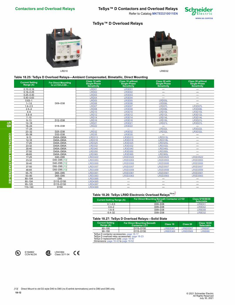
TeSys™ D Overload Relays
LRD10 LR9D32
Table 18.25: TeSys D Overload Relays—Ambient Compensated, Bimetallic, Direct MountingCurrent Setting
Range (A)For Direct Mountingto LC1D/LC2D...
Class 10 withSingle-PhaseSensitivity
Class 10 withoutSingle-PhaseSensitivity
Class 20 withSingle-PhaseSensitivity
Class 20 withoutSingle-PhaseSensitivity
0.10–0.16
D09–D38
LRD01 LR3D01 — —0.16–0.25 LRD02 LR3D02 — —0.25–0.40 LRD03 LR3D03 — —0.40–0.63 LRD04 LR3D04 — —0.63–1 LRD05 LR3D05 LRD05L —1–1.6 LRD06 LR3D06 LRD06L —1.6–2.5 LRD07 LR3D07 LRD07L LR3D07L2.5–4 LRD08 LR3D08 LRD08L LR3D08L4–6 LRD10 LR3D10 LRD10L LR3D10L5.5–8 LRD12 LR3D12 LRD12L LR3D12L7–10 LRD14 LR3D14 LRD14L LR3D14L9–13 D12–D38 LRD16 LR3D16 LRD16L LR3D21L12–18
D18–D38LRD21 LR3D21 LRD21L LR3D21L
16–24 LRD22 LR3D22 — —17–24 — — LRD22L LR3D22L23–32 D25–D38 LRD32 LR3D32 LRD32L LR3D32L30–38 D32–D38 LRD35 LR3D35 — —9-13 D40A–D65A LRD313 LR3D313 LRD313L —12-18 D40A–D65A LRD318 LR3D318 LRD318L —17-25 D40A–D65A LRD325 LR3D325 LRD325L —23-32 D40A–D65A LRD332 LR3D332 LRD332L —30-40 D40A–D65A LRD340 LR3D340 LRD340L —37-50 D40A–D65A LRD350 LR3D350 LRD350L —48-65 D40A–D65A LRD365 LR3D365 LRD365L —17-25 D40–D95 LRD3322 LR3D3322 LR2D3522 LR3D352223-32 D40–D95 [13] LRD3353 LR3D3353 LR2D3553 LR3D355330-40 D40–D95 [13] LRD3355 LR3D3355 LR2D3555 LR3D355537-50 D50–D95 [13] LRD3357 LR3D3357 LR2D3557 LR3D355748-65 D50–D95 [13] LRD3359 LR3D3359 LR2D3559 LR3D355955–70 D65–D95 LRD3361 LR3D3361 LR2D3561 LR3D356163–80 D65–D95 LRD3363 LR3D3363 LR2D3563 LR3D356380–104 D95 LRD3365 — — —80–104 D115–D150 LRD4365 — — —95–120 D115–D150 LRD4367 — — —110–140 D150 LRD4369 — — —
Table 18.26: TeSys LR9D Electronic Overload RelaysCurrent Setting Range (A) For Direct Mounting Beneath Contactor LC1D/
LC2DClass 5/10/20/30
Selectable0.1–0.5 D09–D38 LR9D010.4–2 D09–D38 LR9D021.6–8 D09–D38 LR9D086.4–32 D09–D38 LR9D32
Table 18.27: TeSys D Overload Relays—Solid StateCurrent Setting
Range (A)For Direct Mounting Beneath
Contactor LC1 Class 10 Class 20 Class 10/20Selectable
60–100 D115–D150 LR9D5367 LR9D5567 LR9D6790–150 D115–D150 LR9D5369 LR9D5569 LR9D69
TeSys D contactor accessories: page 18-17TeSys D overload relay accessories: page 18-23TeSys D replacement coils: page 18-40Dimensions: page 18-42 to page 18-52
E164862CCN NLDX
LR43364Class 3211 04
18CONTA
CTORSANDSTA
RTERS-IE
C
[13] Direct Mount to old D2 style D40 to D65 (no Everlink terminations) and to D80 and D95 only.
© 2021 Schneider Electric All Rights ReservedJuly 30, 2021
18-13
www.se.com/us
TeSys™ F Contactors and Overload Relays Contactors and Overload RelaysRefer to Catalog MKTED210011EN
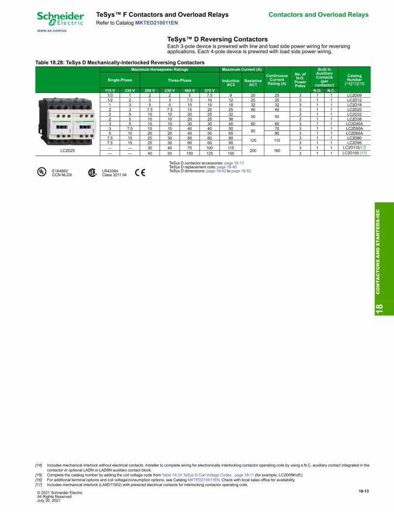
TeSys™ D Reversing ContactorsEach 3-pole device is prewired with line and load side power wiring for reversingapplications. Each 4-pole device is prewired with load side power wiring.
Table 18.28: TeSys D Mechanically-Interlocked Reversing ContactorsMaximum Horsepower Ratings Maximum Current (A)
ContinuousCurrentRating (A)
No. ofN.O.PowerPoles
Built InAuxiliaryContacts
(percontactor)
CatalogNumber
[14][15][16]Single-Phase Three-Phase Inductive
AC3Resistive
AC1115 V 230 V 200 V 230 V 460 V 575 V N.O. N.C.
LC2D25
1/3 1 2 2 5 7.5 9 20 25 3 1 1 LC2D091/2 2 3 3 7.5 10 12 25 25 3 1 1 LC2D121 3 5 5 10 15 18 32 32 3 1 1 LC2D182 3 7.5 7.5 15 20 25 40 40 3 1 1 LC2D252 5 10 10 20 25 32 50 50 3 1 1 LC2D322 5 10 10 20 25 38 3 1 1 LC2D383 5 10 10 30 30 40 60 60 3 1 1 LC2D40A3 7.5 15 15 40 40 50 80 70 3 1 1 LC2D50A5 10 20 20 40 50 65 80 3 1 1 LC2D65A7.5 15 25 30 60 60 80 125 110 3 1 1 LC2D807.5 15 25 30 60 60 95 3 1 1 LC2D95— — 30 40 75 100 115
200 1603 1 1 LC2D115[17]
— — 40 50 100 125 150 3 1 1 LC2D150 [17]
E164862CCN NLDX
LR43364Class 3211 04
TeSys D contactor accessories: page 18-17TeSys D replacement coils: page 18-40TeSys D dimensions: page 18-42 to page 18-52
18CONTA
CTORSANDSTA
RTERS-IEC
[14] Includes mechanical interlock without electrical contacts. Installer to complete wiring for electronically interlocking contactor operating coils by using a N.C. auxiliary contact integrated in thecontactor or optional LADN or LAD8N auxiliary contact block.
[15] Complete the catalog number by adding the coil voltage code from Table 18.24 TeSys D Coil Voltage Codes , page 18-11 (for example, LC2D09KUE).[16] For additional terminal options and coil voltage/consumption options, see Catalog MKTED210011EN. Check with local sales office for availability.[17] Includes mechanical interlock (LA9D11502) with prewired electrical contacts for interlocking contactor operating coils.

18-14 © 2021 Schneider Electric All Rights Reserved
July 30, 2021
Contactors and Overload Relays TeSys™ F Contactors and Overload Relays
www.se.com/us
Refer to CatalogMKTED210011EN
TeSys™ F Non-Reversing ContactorsTable 18.29: TeSys F Contactors—3 Pole
Maximum Three-Phase Horsepower Ratings Maximum Current (A) ContinuousCurrentRating (A)
Number ofPoles
Catalog Number [18][19]
200 V 230 V 460 V 575 V InductiveAC-3
ResistiveAC-1 Panel Mount
with Screws
LC1F330
LC1700, F2100
30 40 75 100 115 200 175 3 LC1F11540 50 100 125 150 250 200 3 LC1F15050 60 125 150 185 275 200 3 LC1F18560 75 150 150 225 315 250 3 LC1F22560 75 150 200 265 350 285 3 LC1F26575 100 200 250 330 400 370 3 LC1F330100 125 250 300 400 500 420 3 LC1F400150 200 400 500 500 700 700 3 LC1F500250 300 600 800 630 1000 1000 3 LC1F630350 400 800 900 800 1000 1000 3 LC1F800350 400 900 — 1000 1000 1250 3 LC1F1000— 450 900 900 780 1600 1350 3 LC1F780
Current Rated
1400 1400 3 LC1F14001700 1700 3 LC1F1700
2100 2100 3 LC1F2100
Table 18.30: TeSys F Coil Voltage Codes [19]
Contactor F115–F150 F185–F225 F265–F330 F400 F500 F630 F780[20] F800[21] F1000 F1400–F2100Coil Suffix Code AC 50/60 Hz
120 V G7 G7 G7 G7 G7 G7 G7 FW G7 G7Coil Part Number (Order Separately) AC 50/60 Hz
120 V LX9FF127 LX9FG127 LX1FH1272 LX1FJ127 LX1FK127 LX1FL110 LX1FX110 LX4F8FW LX1FK065[22] LX1FK070[22]240 V LX9FF220 LX9FG220 LX1FH2402 LX1FJ240 LX1FK240 LX1FL220 LX1FX220 LX4F8MW LX1FK127[22] LX1FK127[22]480 V LX9FF500 LX9FG500 LX1FH5002 LX1FJ500 LX1FK500 LX1FL415 LX1FX415 — LX1FK240[22] LX1FK240[22]
Coil Part Number (Order Separately) DC24 V LX4FF024 LX4FG024 LX4FH024 — — — — — — —
TeSys™ F Overload RelaysTable 18.31: TeSys F 3-Phase Overload Relays—Solid State, Separate Mounting [23]
Current Setting Range A For Direct Mounting to ContactorLC1●●●● Class 10 Catalog Number Class 20 Catalog Number Class 10/20 Selectable Catalog
Number30–50 F115–F185 LR9F5357 LR9F5557 LR9F5748–80 F115–F185 LR9F5363 LR9F5563 LR9F6360–100 F115–F185 LR9F5367 LR9F5567 LR9F6790–150 F115–F185 LR9F5369 LR9F5569 LR9F69132–220 F185[24]–F400 LR9F5371 LR9F5571 LR9F71200–330 F225–F500 LR9F7375 LR9F7575 LR9F75300–500 F330–F500 LR9F7379 LR9F7579 LR9F79380–630 F400–F630, F800 LR9F7381 LR9F7581 —
E164862CCN NLDX
LR43364Class 3211 04
TeSys F contactor accessories: page 18-18TeSys F overload relay accessories: page 18-24TeSys F replacement coils and parts: page 18-41, page 18-40, and page 18-40TeSys F dimensions: page 18-45 and page 18-54
TeSys™ F Reversing Contactors
LC1F265
Components are available for customer assembly of TeSys F reversing contactors. Forexample, the following components must be ordered to build a reversing contactor, 75 hp@ 460 V, with a 120 V / 60 Hz coil:
Table 18.32: Example of ComponentsDescription Quantity Catalog NumberContactors 2 LC1F115G7Lugs (page 18-22) 6 DZ2FF1Auxiliary contacts 2 LADN11Power connections 1 LA9FF976Mechanical interlock 1 LA9FF970
18CONTA
CTORSANDSTA
RTERS-IE
C
[18] Complete the catalog number by adding the coil voltage code from Table 18.24 TeSys D Coil Voltage Codes , page 18-11 (for example, LC1F265G7), or order the contactor (without a coil)and the coil separately. All coils except F780 include 1 N.O. holding circuit interlock contact. The F780 uses two coils that must be wired in series.
[19] For additional pole options and coil voltage options, see Catalog MKTED210011EN. Check with local sales office for availability.[20] LC1F780 contactors operate with 2 coils as a set. The LX1FX• part number includes both coils.[21] Also requires rectifier DR5TE4U for 110–240 V coils.[22] Order 2 coils and connect them in series.[23] When mounting overload relays LR9F5•57–LR9F5•71 and LR9F57–LR9F71 directly beneath the contactor, supporting the relays with a mounting plate is recommended. With overload
relays LR9F7•-LR9F7•81 and LR9F75–LR9F81, use of a support mounting plate is mandatory. Refer to .page 18-24[24] Interconnection kit LA7F407 is required to mount an LR9F5●71 and LR9F71 to an LC1F185.

© 2021 Schneider Electric All Rights ReservedJuly 30, 2021
18-15
www.se.com/us
TeSys™ K Contactors Contactor AccessoriesRefer to Catalog MKTED210011EN
Table 18.33: 3-Pole ContactorsMaximum Three-PhaseHorsepower Ratings
Maximum Current (A) ContinuousCurrentRating (A)
Holding CircuitContact BuiltInto Coil
CatalogNumber [25]Inductive
AC3Resistive
AC1200 V 230 V 460 V 575 V N.O. N.C.30 40 75 100 115 200 175 1 0 LC1F11540 50 100 125 150 250 200 1 0 LC1F15050 60 125 150 185 275 200 1 0 LC1F18560 75 150 150 225 315 250 1 0 LC1F22560 75 150 200 265 350 285 1 0 LC1F26575 100 200 250 330 400 370 1 0 LC1F330100 125 250 300 400 500 420 1 0 LC1F400150 200 400 500 500 700 700 1 0 LC1F500250 300 600 800 630 1000 1000 1 0 LC1F630350 400 800 900 800 1000 1000 0 0 LC1F800— 450 900 900 780 1600 1350 0 0 LC1F780
Table 18.34: Auxiliary Contact (Electrical Interlocking)—2 must be purchased
For use with Number ofContacts
Maximum Numberof Blocks
Per Contactor
Contact Arrangement CatalogNumberN.O. N.C.
LC1Fto be orderedseparately
1 1 1 — LADN10 [26]— 1 LADN01
2 21 1 LADN112 — LADN20 [26]
4 2
2 2 LADN221 3 LADN134 — LADN40 [26]— 4 LADN043 1 LADN312 2 LADC22 [27]
Table 18.35: Accessories—For the Assembly of 3-Pole Reversing Contactors(Horizontal Mounting)
With 2 IdenticalContactors [28]
Set of Power ConnectionsCatalog Number
Horizontal MountingMechanical Interlock Kit
Catalog NumberLC1F115 LA9FF976 LA9FF970LC1F150 LA9F15076 LA9FF970LC1F185 LA9FG976 LA9FG970LC1F225 LA9F22576 LA9FG970LC1F265 LA9FH976 LA9FJ970LC1F330 LA9FJ976 LA9FJ970LC1F400 LA9FJ976 LA9FJ970LC1F500 LA9FK976 LA9FJ970
LC1F630, F800 LA9FL976 LA9FL970
TeSys F contactor accessories: page 18-18TeSys F overload relay accessories: page 18-24TeSys F replacement coils and parts: page 18-41, page 18-40, and page 18-40TeSys F dimensions: page 18-45
E164862CCN NLDX
LR43364Class 3211 04
TeSys™ K Contactors
LA1KN22
Table 18.36: Instantaneous Auxiliary Contact Blocks[1]Clip-on front mounting, 1 block per contactor and 2 blocks per pair of mechanically interlocked contactors
Type of connection Auxiliary Contacts CatalogNumberN.O. N.C.
Screw clamp
2 — LA1KN20— 2 LA1KN021 1 LA1KN114 — LA1KN40 [2]3 1 LA1KN31 [2]2 2 LA1KN22 [2]1 3 LA1KN13 [2]— 4 LA1KN04 [2]
Table 18.37: Electronic Time Delay Auxiliary Contact BlocksClip-on front mounting, 1 block per contactor and 2 blocks per pair of mechanically interlocked contactors
Voltage (V) Type Timing Range(S) Contacts Catalog
Number24–48 Vac or Vdc On-delay 1–30 SPDT LA2KT2E110–240 Vac On-delay 1–30 SPDT LA2KT2UNOTE: Relay outputs, with single pole double throw, 240 Vac/Vdc, 2 A max.Maximum switching capacity 250 VA / 150 WOperating temperature: –10 to + 60°C (14 to 140°F)Reset time: 1.5 s during time delay, 0.5 after time delay
18CONTA
CTORSANDSTA
RTERS-IEC
[25] Complete the catalog number with the coil voltage code from and (for example, LC1F115G7). All coils except F780 include 1 N.O. holding circuit interlock contact. The F780 uses 2 coils thatmust be wired in series.
[26] Cannot be used for interlocking.[27] Including 1 N.O. + 1 N.C. make-before-break overlapping contacts.[28] For two contactors of different size, refer to page 18-22.[1] For additional terminal options, see Catalog MKTED210011EN. Check with local sales office for availability.[2] Block of 4 contacts cannot be used with LP4K or LP5K contactors.

18-16 © 2021 Schneider Electric All Rights Reserved
July 30, 2021
Contactor Accessories TeSys™ K Contactors
www.se.com/us
Refer to CatalogMKTED210011EN
LA2KT2U
Table 18.38: Suppressor Module with Incorporated LED IndicatorClip-on front mounting
Voltage range Type Sold inlots of
CatalogNumber
12–24 Vac/Vdc Varistor 5 LA4KE1B [3]32–48 Vac/Vdc Varistor 5 LA4KE1E [3]50–129 Vac/Vdc Varistor 5 LA4KE1FC [3]130–250 Vac/Vdc Varistor 5 LA4KE1UG [3]12–24 Vdc Diode + Zener 5 LA4KC1B [4]32–48 Vdc Diode + Zener 5 LA4KC1E [4]220–250 Vac RC 5 LA4KA1U [5]
Table 18.39: Power ConnectorsDescription Sold in
lots ofCatalogNumber
Set of 6 power connections for reversing contactors with screw-clampterminals 100 LA9K0969
E164862CCN NLDX LR43364
Class 3211 04
Table 18.40: Accessories for Overload RelaysDescription Type of Connection Catalog
NumberTerminal block for separate clip-on mounting of the overload relay onto35 mm omega rail (AM1DP200) Screw-clamp LA7K0064
18CONTA
CTORSANDSTA
RTERS-IE
C
[3] Protection by limitation of the transient voltage to 2 Uc maximum. Maximum reduction of the transient voltage peaks. Slight time delay on drop-out (1.1–1.5 times normal).[4] No overvoltage or oscillation frequency. Polarized component. Slight time delay on drop-out (1.1–1.5 times normal).[5] Protection by limitation of the transient voltage to 3 Uc maximum and limitation of the oscillation frequency. Slight time delay on drop-out (1.2 times normal).

© 2021 Schneider Electric All Rights ReservedJuly 30, 2021
18-17
www.se.com/us
TeSys™ D and F Contactors Contactor AccessoriesRefer to Catalog MKTED210011EN
TeSys™ D and FAuxiliary Contacts, Time Delay, Mechanical Latch
Front Mounted Auxiliary Blocks
Table 18.41: Standard, Instantaneous Auxiliary Contact BlocksSnap-OnMounting
Number ofContacts
ContactArrangement Catalog Number [6]
N.O. N.C.
To the front ofLC●DT20–D258 (4P),LC●D09–D150 [6]orTo the right side ofLC●F
4 [6]
2 2 LADN22 [7]1 3 LADN13 [7]4 0 LADN40 [7]0 4 LADN04 [7]3 1 LADN31 [7]2 2 LADC22 [7] [8]
21 1 LADN11 [7]2 0 LADN20 [7]0 2 LADN02 [7]
To the front ofLC●D80–D150orTo the left side ofLC●F
1
1 0 LADN10 [9]
0 1 LADN01 [9]
To the side ofLC●D09 to D150 only(not for use on TeSys F)
21 1 LAD8N11 [10]
2 0 LAD8N20 [10]
Table 18.42: Instantaneous Blocks with Dust-Tight Auxiliary Contacts (IP54)NEMA 12
Snap-OnMounting
Standard Contacts Dust-Tight Contacts Catalog NumberN.O. N.C. N.O. N.C.
To the front ofLP●D40–D80, LC●DT20–D258 (4P),LC●D09 to D95orTo the right side ofLC●F
— — 2 — LA1DX202 — 2 — LA1DZ401 1 2 — LA1DZ31
— — 2 — LA1DY20 [11]
Table 18.43: Pneumatic Time Delay Contact BlocksSnap-OnMounting
Time DelayContacts Type Range of
Time DelayCatalog Number
[12]N.O. N.C.
To the front ofLP●D40–D80,LC●DT20–D258 (4P),LC●D09 to D150orTo the right side ofLC●F
1 1 On energization(on delay)
0.1 to 3 s [13] LADT00.1 to 30 s LADT210 to 180 s LADT41 to 30 s [14] LADS2
1 1On de-energization(off-delay)
0.1 to 3 s [13] LADR00.1 to 30 s LADR210 to 180 s LADR4
Table 18.44: Mechanical Latch Blocks with Manual or Electrical Unlatch(TeSys D only)
Front snap-onmounting onto Application Catalog Number [15]
LC●D09 to D65A For silent operation andenergy conservation LAD6K10 [16][17]
LC1D80 to D150, LP1D80 For silent operation andenergy conservation LA6DK20 [16]
Table 18.45: Coil Voltage Codes for LAD6K/LA6DK Mechanical Latch BlocksVolts 24 110/
127220/240
AC or DC B F M
E164862CCN NLDX LR43364
Class 3211 04
TeSys D contactors: page 18-11 and page 18-13TeSys D overload relay accessories: page 18-23TeSys D replacement coils: page 18-40TeSys D dimensions: page 18-42 to page 18-52
18CONTA
CTORSANDSTA
RTERS-IEC
[6] For low consumption coils (LC1D09–D38 only), only one front-mounted two-contact block allowed. No side-mounted contact blocks allowed.[7] For spring terminal versions of these blocks, add a 3 to the end of the catalog number (for example, LADN223). For slip-on versions, add 9 to the end of the catalog number (for example,
LADN229).[8] Including 1 N.O. + 1 N.C. make-before break overlapping contacts.[9] This block cannot be added to the LC1D 09–D38 contactors; a maximum of 2 blocks can be mounted on the LC1D40A-LC1/LP1D80 contactors only.[10] 1 block may be added to the left side of LC1D09–D38, AC coils only; only 1 block may be added to either side of the LC1D40A-D80 contactors, AC coils only. Cannot be installed on TeSys
D contactors with DC coils.[11] Device supplied with 4 ground terminal points.[12] For spring terminal versions of these blocks, add a 3 to the end of the catalog number (for example, LADT23).[13] Scale range is expanded between 0.1 and 0.6 seconds on the dial for more accurate settings at the lower end of the range.[14] Switching time between the opening of the N.C. contact and the closing of the N.O. contact: 40 ms ± 15 ms .[15] To complete the catalog number, add the coil voltage code from Table 18.45. For additional voltage options, see Catalog MKTED210011EN. Check with local sales office for availability.[16] Does not include internal coil clearing contact.[17] Low consumption DC contactors (and relays) (code coil ●L) are not compatible with the LAD6K10● mechanical latching blocks.
18-18 © 2021 Schneider Electric All Rights Reserved
July 30, 2021
Contactor Accessories TeSys™ D and F Accessories
www.se.com/us
Refer to CatalogMKTED210011EN
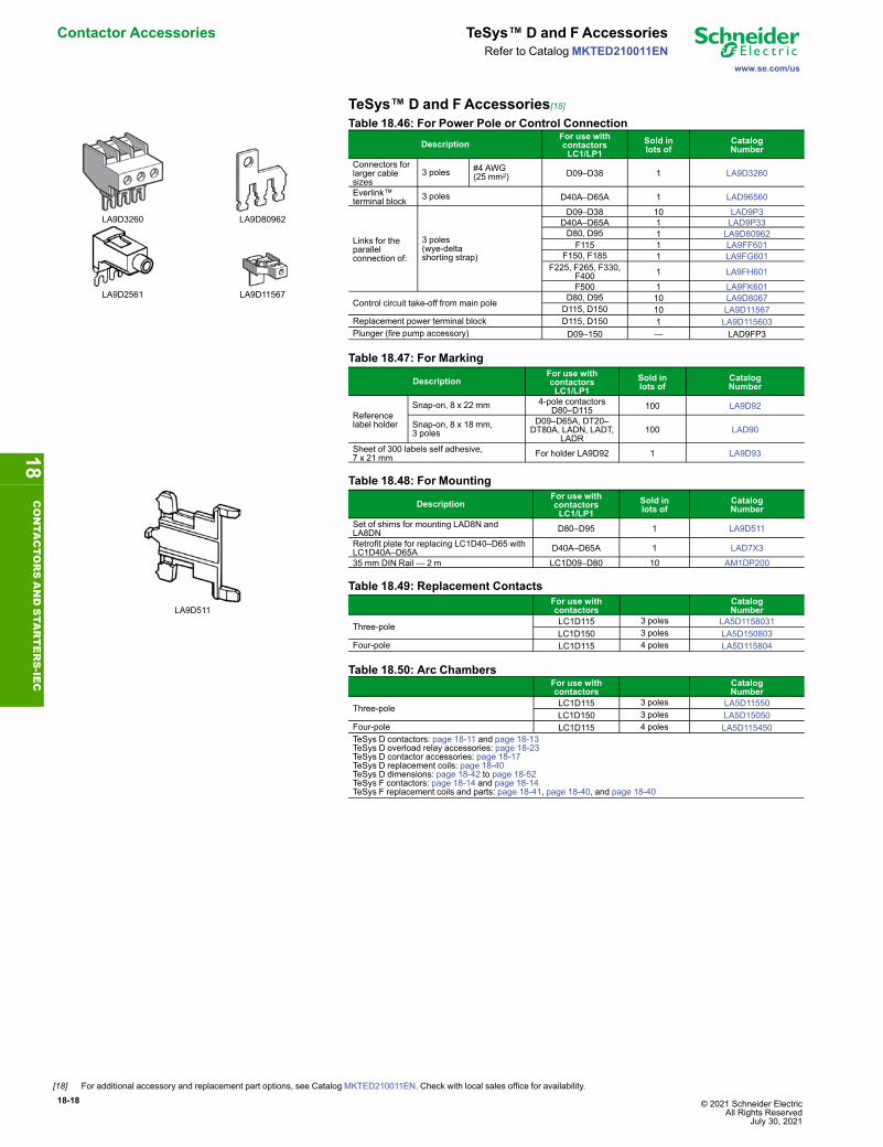
TeSys™ D and FAccessories[18]
LA9D3260 LA9D80962
LA9D2561 LA9D11567
Table 18.46: For Power Pole or Control ConnectionDescription
For use withcontactorsLC1/LP1
Sold inlots of
CatalogNumber
Connectors forlarger cablesizes
3 poles #4 AWG(25 mm2) D09–D38 1 LA9D3260
Everlink™terminal block 3 poles D40A–D65A 1 LAD96560
Links for theparallelconnection of:
3 poles(wye-deltashorting strap)
D09–D38 10 LAD9P3D40A–D65A 1 LAD9P33D80, D95 1 LA9D80962F115 1 LA9FF601
F150, F185 1 LA9FG601F225, F265, F330,
F400 1 LA9FH601
F500 1 LA9FK601
Control circuit take-off from main pole D80, D95 10 LA9D8067D115, D150 10 LA9D11567
Replacement power terminal block D115, D150 1 LA9D115603Plunger (fire pump accessory) D09–150 — LAD9FP3
Table 18.47: For Marking
DescriptionFor use withcontactorsLC1/LP1
Sold inlots of
CatalogNumber
Referencelabel holder
Snap-on, 8 x 22 mm 4-pole contactorsD80–D115 100 LA9D92
Snap-on, 8 x 18 mm,3 poles
D09–D65A, DT20–DT80A, LADN, LADT,
LADR100 LAD90
Sheet of 300 labels self adhesive,7 x 21 mm For holder LA9D92 1 LA9D93
LA9D511
Table 18.48: For Mounting
DescriptionFor use withcontactorsLC1/LP1
Sold inlots of
CatalogNumber
Set of shims for mounting LAD8N andLA8DN D80–D95 1 LA9D511
Retrofit plate for replacing LC1D40–D65 withLC1D40A–D65A D40A–D65A 1 LAD7X3
35 mm DIN Rail — 2 m LC1D09–D80 10 AM1DP200
Table 18.49: Replacement ContactsFor use withcontactors
CatalogNumber
Three-pole LC1D115 3 poles LA5D1158031LC1D150 3 poles LA5D150803
Four-pole LC1D115 4 poles LA5D115804
Table 18.50: Arc ChambersFor use withcontactors
CatalogNumber
Three-pole LC1D115 3 poles LA5D11550LC1D150 3 poles LA5D15050
Four-pole LC1D115 4 poles LA5D115450TeSys D contactors: page 18-11 and page 18-13TeSys D overload relay accessories: page 18-23TeSys D contactor accessories: page 18-17TeSys D replacement coils: page 18-40TeSys D dimensions: page 18-42 to page 18-52TeSys F contactors: page 18-14 and page 18-14TeSys F replacement coils and parts: page 18-41, page 18-40, and page 18-40
18CONTA
CTORSANDSTA
RTERS-IE
C
[18] For additional accessory and replacement part options, see Catalog MKTED210011EN. Check with local sales office for availability.

© 2021 Schneider Electric All Rights ReservedJuly 30, 2021
18-19
www.se.com/us
TeSys™ D Contactors Contactor AccessoriesRefer to Catalog MKTED210011EN
RC and Varistor Coil Suppressors
LA4DA1U
RC Coil Suppressor• Limitation of transient voltage to 300% of nominal voltage maximum.• Oscillating frequency limited to 400 Hz maximum. Slight increase in drop-out time(1.2–2 times normal).
Table 18.51: Resistor/Capacitor Circuit (RC) for Reduction of Electrical Noise in ACContactor CoilsInstalled by Mounting on Operating Voltage 50/60 Hz Catalog
Number
Snapping into the cavity on the rightside without tools [19]
LC●D09–D38 (3P),LC1DT20–DT40 (4P)
24–28 Vac LAD4RCE50–127 Vac LAD4RCG110–240 Vac LAD4RCU
Snap-on mounting, and connectionwithout tools to the contactor coilterminals
LC1D40A–65A (3P),LC1DT60A–DT80A
(4P)
24-48 Vac LAD4RC3E50–127 Vac LAD4RC3G110–240 Vac LAD4RC3U380–415 Vac LAD4RC3N
Screw connection to the contactor coilterminals
LC●D80–D150 (3P),LC1D80–D115 (4P)
24–48 Vac LA4DA2E50–127 Vac LA4DA2G110–240 Vac LA4DA2U380–415 Vac LA4DA2N
Varistor Coil Suppressor[20]• Limitation of transient voltage value to 200% of nominal voltage maximum.• Maximum reduction of transient voltage peaks. Slight increase in drop-out time (1.1–1.5 times normal).
Table 18.52: Varistor (Peak Limiting) for Reduction of Electrical Noise in ACContactor CoilsInstalled by Mounting on Operating Voltage Catalog
NumberSnapping into the cavity on the rightside without tools [19]
LC●D09–D38 (3P),LC1DT20–DT40 (4P)
24–48 Vac LAD4VE110–250 Vac LAD4VU
Snap-on mounting, and connectionwithout tools to the contactor coilterminals
LC1D40A–D65A (3P),LC1DT60A–DT80A
(4P)
24–48 Vac/Vdc LAD4V3E
110–250 Vac/Vdc LAD4V3U
Screw connection to the contactor coilterminals
LC●D80–D115 (3P)LC1D80–D115 (4P)
24–48 Vac LA4DE2E110–250 Vac LA4DE2U
Screw connection to the contactor coilterminals
LC●D80–D95 (3P)LC1D80 (4P)
24–48 Vdc LA4DE3E110–250 Vdc LA4DE3U
Diode Coil Suppressor
LA4DC3U
• No overvoltage or oscillating frequency.• Polarized component. Increased drop-out time (6–10 times normal).
Table 18.53: Diode for Reduction of Electrical Noise in DC Contactor CoilsInstalled on the upper part by Mounting on Operating Voltage, DC Catalog
NumberSnap-on mounting and connection w/otools to the contactor coil terminals
LC●D09 to D38 (3P),LC1DT20 to DT40 (4P) 24–250 Vdc LAD4DDL
Clip-on front mountingLC●D40A to D65A
(3P),LC1DT60A to DT80A
(4P)24–250 Vdc LAD4D3U
Screw connection of wire to thecontactor coil terminals
LC●D80 to D95 (3P),LC1D80 (4P) 24–250 Vdc LA4DC3U
18CONTA
CTORSANDSTA
RTERS-IEC
[19] Installing the suppressor into the cavity makes the electrical connection. Overall width of the contactor remains the same.[20] For additional accessory and replacement part options, see Catalog MKTED210011EN. Check with local sales office for availability.

18-20 © 2021 Schneider Electric All Rights Reserved
July 30, 2021
Contactor Accessories TeSys™ D Contactors
www.se.com/us
Refer to CatalogMKTED210011EN
Bidirectional Diode Coil Suppressor• Protection provided by limiting the transient voltage to 2 Uc max.• Maximum reduction of transient voltage peaks
LAD4T3B
Table 18.54: Bidirectional Peak Limiting Diode[21]
Installed by Mounting onOperating Voltage Catalog
NumberVac (50/60 Hz) Vdc
Snapping into the cavity on theright side of the contactor [22]
LC●D09–D38 (3P)[23]
LC1DT20–DT40 (4P)
24 — LAD4TB
— 24 LAD4TBDL
Clip-on front mounting andconnection without toolsto the contactor coil terminals [23]
LC●D40A–D65A(3P), LC1DT60A–
DT80A (4P)12–24 12–24 LAD4T3B
Screw mounting [24] LC●D80–D95 (3P),LC1D80 (4P) — 24 LA4DB3B
LAD4BB●●
Table 18.55: Cabling Accessories[21]Usage Mounting on Operating Voltage 50/60
Hz Catalog Number
For adapting existing wiring to a new productor for use with top-mounting accessory. LC1D09–D38
Without coil suppression LAD4BBWith coilsuppression(varistor)
24–48 Vac LAD4BBVE
50–127 Vac LAD4BBVG
For adapting existing wiring to a new productor for use with top-mounting accessory LC1D40A–D65A Without coil suppression LAD4BB3
TeSys D contactors: page 18-11 and page 18-13TeSys D contactor accessories: page 18-17TeSys D overload relay accessories: page 18-23TeSys D replacement coils: page 18-40TeSys D dimensions: page 18-42 to page 18-52
TeSys™ D Electronic Timers and Interface Modules
LA4DFB
The following accessories require use of cabling accessories (LAD4BB●●) for propermounting. See page 18-20 for illustration.
Table 18.56: Electronic Serial Timer ModulesType Operational Voltage [25] Time Delay Catalog Number
24–250 Vac 100–250 Vac
On-delay LC1D09–D65A LC1D80–D1500.1–2 s LA4DT0U1.5–30 s LA4DT2U25–500 s LA4DT4U
LAD9ET1S
LADN22S
LU9ET1S
Table 18.57: Interface Modules[21]Interface Type [26] Operational Voltage Input Voltage Catalog Number
24–250 Vac 100–250 VacRelay LC1D09–D150 — 24 Vdc LA4DFB
Solid State LC1D09–D65A LC1D80–D115 24 Vdc LA4DWB
Table 18.58: TeSys Safety-Chain Identification SystemDescription Compatibility Package
Qty Catalog Number
Red retrofit contactor safetycover
LC1D09–D65A,CAD32, CAD50 10 LAD9ET1S
LC1D80 1 LAD9ET3SLC1D115–D150 1 LAD9ET4S
Red auxiliary contact block,2 N.O. + 2 N.C.
LC1D09–D150,CAD32, CAD50 1 LADN22S
Red retrofit safety sticker TeSys U 10 LU9ET1S
18CONTA
CTORSANDSTA
RTERS-IE
C
[21] For additional voltage and accessory options, see Catalog MKTED210011EN. Check with local sales office for availability.[22] Installing the suppressor into the cavity makes the electrical connection. Overall width of the contactor remains the same.[23] For LC•D09–LC•D65A with DC or low consumption DC coils, 3–pole contactors are fitted wit built-in bidirectional diode suppression as standard.[24] Mounting at the top of the contactor on coil terminals A1 and A2.[25] For 24 V operation, the contactor must be fitted with a 21 V coil: coil voltage code Z5 for 50 Hz; Z6 for 60 Hz; and ZD for DC.[26] Adapter required for D09–D65A, see .

18-21
www.se.com/us
TeSys™ D Contactors Contactor AccessoriesRefer to Catalog MKTED210011EN
TeSys™ D Reversing ContactorsTable 18.59: Components and Kits for Reversing Assemblies[27]
Description For contactor(2 identical contactors) Part Number
Kits for Assembly of Reversing Contactors
LAD 9R1
Kit comprising of:
• Mechanical interlock• Electrical wiring links
• Power wiring links
LC1 D09 to D38 LAD9R1V
LC1 DT20 to DT40 LADT9R1V
LA9 D8069
Kit comprising of:
• Mechanical interlock
• Power wiring links
LC1 D09 to D38 LAD9R1
LC1 D40A to D65A LAD9R3
For Contactor(2 Identical Contactors) Mechanical Interlock
Mechanical Interlockwith Integral Electrical
InterlockingReversing Power Links(Parallel and Reverser)
Components for Assembly of Reversing ContactorsLC1 D40A to D65A LAD4CM — LA9D65A69LC1 D80 to D95 (AC coil) LA9D50978 LA9D4002 LA9D8069LC1 D80 to D95 (DC coil) LA9D80978 LA9D8002 LA9D8069LC1 D115 to LC1D 150 — LA9D11502 LA9D11569
TeSys D contactors: page 18-11 and page 18-13TeSys D contactor accessories: page 18-17TeSys D replacement coils: page 18-40TeSys D dimensions: page 18-42 to page 18-52
18CONTA
CTORSANDSTA
RTERS-IEC
[27] For additional reversing accessory options, see Catalog MKTED210011EN. Check with local sales office for availability.
© 2021 Schneider Electric All Rights ReservedJuly 30, 2021

18-22 © 2021 Schneider Electric All Rights Reserved
July 30, 2021
Contactor Accessories TeSys™ F Contactors
www.se.com/us
Refer to CatalogMKTED210011EN
TeSys™ F Reversing Contactors[28]
LA9F●970
LA9F●976
Table 18.60: Component Parts for the Assembly of F-Line 3-pole ReversingContactorsWith 2 Identical Contactors Set of Power Connections Cat. No. Mechanical Interlock Kit Cat. No.Horizontal Mounting
LC1F115 LA9FF976 LA9FF970LC1F150 LA9F15076 LA9FF970LC1F185 LA9FG976 LA9FG970LC1F225 LA9F22576 LA9FG970LC1F265 LA9FH976 LA9FJ970LC1F330 LA9FJ976 LA9FJ970LC1F400 LA9FJ976 LA9FJ970LC1F500 LA9FK976 LA9FJ970
LC1F630 or F800 LA9FL976 LA9FL970
TeSys™ F Contactors
LA9D09981, LA9F980
Table 18.61: Suppressor BlocksOperating limit: up to 220 V, 50/60 Hz coils
Description For Use with coilsCatalogNumber
Suppressor block(clip-on mounting tocoil)
LX1FH, F265, F330 LA9F980LX1FJ, FK, FL, FX, F400, F500, F630, F780, LX9FF, FG, FH, F115,F150, F185, F225, F265, F330 LA9D09980
Mounting bracket (for 35 mm DIN rail or panel mounting) for suppressor block LA9D09981
Table 18.62: Lugs and Terminal Shrouds for TeSys F ContactorsContactorType LC1
Cable SizeAWG Range
Lug Kit(Quantity of 6)
Individual Lug(Quantity of 1)
F115 14 to 2/0 DZ2FF6 DZ2FF1F150, F185 6 to 3/0 DZ2FG6 DZ2FG1
F225, F265, F330 6 to 300 MCM DZ2FH6 DZ2FH1F400 4 to 500 MCM DZ2FJ6 DZ2FJ1F500 2 x 2 to 600 MCM DZ2FK6 DZ2FK1F630 3 x 2 to 600 MCM DZ2FL6 DZ2FL[29]F800 3 x 2 to 600 MCM DZ2FL6 —F780 4 x 1/0 to 750 MCM DZ2FX6 —
Table 18.63: Lugs and Terminal Shrouds for TeSys F Contactor with TeSys F Overload Relay [30]
Contactor Type LC1 Overload Relay(Direct Mount to Contactor)
Contactor Line Side Lug(Qty)
Line Side Cable Size AWGRange
Overload Load Side Lug(Qty)
Load Side Cable Size AWGRange
F115 LR9F5•57–F5•69, LR9F57–F69 DZ2FF1 (3) 14 to 2/0 DZ2FG1 (3) 6 to 3/0
F150, F185 LR9F5•57–F5•71, LR9F57–F71 DZ2FG6 (1) 6 to 3/0 (included with line side lugkit) 6 to 3/0
F225, F265 LR9F5•71, LR9F71 DZ2FG6 (1) 6 to 300 MCM (included with line side lugkit) 6 to 300 MCM
F265, F330 LR9F7•75–F7•79, LR9F75–F79 DZ2FH1 (3) 6 to 300 MCM — 4 to 500 MCMF400 LR9F7•75–F7•81, LR9F75–F81 DZ2FJ1 (3) 4 to 500 MCM — 4 to 500 MCMF500 LR9F7•75–F7•81, LR9F75–F81 DZ2FK1 (3) 2 X 2 to 600 MCM — 4 to 500 MCM
F630 LR9F7•81, LR9F81DZ2FL1 (1)DZ2FL2 (1)DZ2FL3 (1)
3 X 2 to 600 MCM DZ2FR1 (1) 4 to 500 MCM
These clear plastic protective shrouds are an effective means to meet internationaltouch-safe requirements for power terminals. They are designed to be used with powercables that have been bolted to the terminal.NOTE: The protection shrouds do not attach to contactors or overloads using DZ2Flug kits.
18CONTA
CTORSANDSTA
RTERS-IE
C
[28] For additional reversing accessory options, see Catalog MKTED210011EN. Check with local sales office for availability.[29] For 2–pole F630 contactors, order two DZ2FL1 (L1 and T2), and two DZ2FL3 (L2 and T1). For 4–pole F6304, order two DZ2FL1 (L1 and T4), four DZ2FL2 (L2, T2, L3, T3) and two DZ2FL3
(L4 and T1).[30] Lug kits ending in the number 6 include 6 identical lugs. In some cases the LR9F overload relay mounted directly on the load side of an LC1F contactor will require a different size lug for
your choice of contactor and overload. If the two sizes are different, order 3 of each size lug. Mounting hardware (screws, washers, and nuts) are provided with the contactors and overloadrelays, not with the lugs.

© 2021 Schneider Electric All Rights ReservedJuly 30, 2021
18-23
www.se.com/us
TeSys™ D and F Overload Relays Overload Relay AccessoriesRefer to Catalog MKTED210011EN
LA9F70●
Table 18.64: Power Terminal Protection ShroudsFor Use With 2-, 3-, And 4-pole Contactors
Number ofShroudsPer Set
Catalog Number
LC1F115 6 LA9F701LC1F150, F185 6 LA9F702LC1F225, F265, F330, F400 and F4002, F500 and F5002 6 LA9F703LC1F630, F6302 and F800 6 LA9F704LC1F1154 8 LA9F706LC1F1504 and F1854 8 LA9F707LC1F2254, F2654, F3304, F4004, F5004 8 LA9F708LC1F6304 8 LA9F709For contactors LC1F115, LC1F150, and LC1F185, an available touch-safe terminal blockmay be used in place of lugs for power connections.
Table 18.65: Insulated Terminal BlocksFor contactor type LC1 For overload relay LR9 Maximum Cable Size Catalog Number
F115, F150, F185 F5●57, F5●63, F5●67, F5●69,F57, F63, F67, F69 300 MCM LA9F103
TeSys F contactor accessories: page 18-18TeSys F overload relay accessories: page 18-24TeSys F replacement coils and parts: page 18-41, page 18-40, and page 18-40TeSys F dimensions: page 18-45, page 18-54
TeSys D Overload Relay Accessories
LA7D901
Table 18.66: Mounting Kits and Plates[1]Description For use with overload relays: Cat. No.
Separate mounting kits for mounting to35 mm DIN rail or for panel mountingwith screws
LRD01–35 and LR3D01–35 LAD7B10LRD01–35 and LRD01–35 for ring tongue terminals LAD7B106LRD04L–-32L, LR3D04L–32L, and LR9D01–32 LAD7B205LRD3●●●, LR3D3●●●, LR2D35●● LAD96560
LA7D03
Table 18.67: AccessoriesDescription For use with Standard
PackageCatalogNumber
Prewiring kit allows direct connection ofthe N.C. contact of relay LRD01–D32 orLR3D01–D32 to the contactor
LC1D09 to D18 10 LAD7C1LC1D25 to D38 10 LAD7C2
Remote stop/tripping or electrical reset[2]
LRD01-D32, LRD3, LR3D01-D32, LR3D3 1 LAD703 [3]All relays except LRD01–D32, LR3D01–D31 1 LA7D03 [3]
Reset by flexible cable 500 mm (19.6 in.) LRD01-D32, LRD3, LR3D3 1 LAD7305
Table 18.68: Control Circuit Voltages for LA7D03 and LAD703Volts 24 110
AC 50/60 Hz B FDC B F
18CONTA
CTORSANDSTA
RTERS-IEC
[1] When using mounting plates, separate mounting kits are also required.[2] The time that the LA7D03 can remain energized depends on its rest time; 1 s pulse with 9 s rest time; 5 s pulse with 30 s rest time; 10 s pulse with 90 s rest time; maximum pulse duration of
20 s with rest time of 300 s. Consumption on inrush and sealed: < 100 VA[3] Part number to be completed by adding coil voltage code, (for example, LAD703F).

18-24 © 2021 Schneider Electric All Rights Reserved
July 30, 2021
Overload Relay Accessories TeSys™ D and F Overload Relays
www.se.com/us
Refer to CatalogMKTED210011EN
TeSys F Overload Relay Accessories
LA7F90●
Table 18.69: Mounting Plate for Overload RelayFor use with relays Catalog NumberLR9F5●57, F5●63, F5●67, F5●69, F5●71, F57, F63, F67, F69, and F71 LA7F901LR9F7●75, F7●79, F5●81, F75, F79, and F81 LA7F902These clear plastic protective shrouds are an effective means to meet internationalfinger-safe requirements for power terminals. They are designed to be used with powercables that have been bolted to the terminal.NOTE: Protection shrouds do not attach to contactors/overloads using DZ2F lug kits.
LA9F70●
Table 18.70: Power Terminal Protection Shrouds, Single-PoleFor use with relays Catalog NumberLR9F5●57, F57 LA9F701LR9F5●63, F5●67, F5●69, F63, F67, F69 LA9F702LR9F5●71, F71 LA9F705LR9F7●75, F7●79, F7●81, F75, F79, F81 LA9F703
Table 18.71: Power Terminal Protection Shrouds, 3-PoleFor use with relays Catalog NumberLR9F5●57, F5●63, F5●67, F5●69, F57, F63, F67, F69 LA7F701LR9F5●71, F71 LA7F702LR9F7●75, F7●79, F7●81, F75, F79, F81 LA7F703
LA7F701
Table 18.72: Connection Accessories (for Mounting Overload Relays BeneathReversing Contactors)[4]Application Set of 3 Busbars
Catalog NumberFor relays For contactorLR9F5●71, F71 LC1F185 LA7F407LR9F5●71, F71 LC1F225 and F265 LA7F403LR9F7●75, F5●79, F75, F79 LC1F225 to F400 LA7F404LR9F7●81, F81 LC1F400 LA7F404LR9F7●81, F81 LC1F630 and F800 LA7F406
TeSys D dimensions: page 18-50 and page 18-52TeSys F dimensions: page 18-45, page 18-54
18CONTA
CTORSANDSTA
RTERS-IE
C
[4] Mounting plate required.

© 2021 Schneider Electric All Rights ReservedJuly 30, 2021
18-25
www.se.com/us
TeSys™ U Open Motor Starter Motor Starters and ProtectorsRefer to Catalog MKTED210011EN
TeSys™ U Motor Starter
The TeSys U motor starter is integrated, making itsimple to choose and install. It consists of a controlunit snapped in a power base. TeSys U can beconfigured to fit specific applications as well.Optional accessories include a reverser, a currentlimiter, predictive maintenance options, andcommunication options.For detailed information about TeSys U, visit ourwebsite.
1 Power Base
+2 Control Unit
+3 Optional Accessories(Type E Line Spacer,Function Modules,Auxiliary Contacts etc.)
= TeSys UMotor Starter
Selecting TeSys U Motor Starters in Three Steps
Power Base LUB12 Power Base LUB120 Control Unit
Table 18.73: Step 1. Select Power Base (Only two different bases up to 32 A)
ControlConnection
Max.Current(A)
Maximum Horsepower Ratings Self-ProtectedStarter BaseThree-Phase Single-Phase
200 V 230 V 460 V 575 V 115 V 230 V CatalogNumber
With non-removablescrew terminations
12 3 3 7.5 10 0.5 2 LUB1232 10 10 20 25 2 5 LUB32
Without screwterminations
12 3 3 7.5 10 0.5 2 LUB120 [1]32 10 10 20 25 2 5 LUB320 [1]
Table 18.74: Step 2. Select Control Unit [2]Setting Range
(A)Standard3-phase
Class 10 trip [3]
Advanced3-phase
Class 10 trip [3]
Advancedsingle-phaseClass 10 trip [3]
Advanced3-phase
Class 20 trip [3]0.15–0.6 LUCAX6●● LUCBX6●● LUCCX6●● LUCDX6●●0.3–1.4 LUCA1X●● LUCB1X●● LUCC1X●● LUCD1X●●1.25–5.0 LUCA05●● LUCB05●● LUCC05●● LUCD05●●3–12 LUCA12●● LUCB12●● LUCC12●● LUCD12●●4.5–18 LUCA18●● LUCB18●● LUCC18●● LUCD18●●8–32 LUCA32●● LUCB32●● LUCC32●● LUCD32●●
Table 18.75: Voltage CodesVolts 24 110–240DC BL [4] —AC B —
DC or AC — FU
Table 18.76: Step 3. Select Auxiliary Contacts (optional)
Terminals ContactIndicates
Contact NormalStatus
Contact State for Each Mode [5]CatalogNumberOff Ready Run Short
Circuit TripOverload Trip(Manual Reset)
Overload Trip(Remote/AutoReset) [6]
Auxiliary Contact
Auxiliary Contact Blocks
ScrewReady condition N.O. O I I O O I LUA1C11Fault condition N.C. I I I O O I
ScrewReady condition N.O. O I I O O I LUA1C20Fault condition N.O. O O O I I O
Auxiliary Contact Function ModulesScrew Pole state 2 N.O. O O I O O LUFN20Screw Pole state 1 N.O. and 1 N.C. O I O I I O O I O I LUFN11
Screw Pole state 2 N.C. 1 I O I I LUFN02
Table 18.77: AccessoriesAccessory Quick Description For details & selection, see:
Current limiter Increases the breaking capacity to 130 kA @ 460 Vand to 65 kA @ 575 V page 18-27Reverser Stacked or side mounted (LU6MB0●●● only) page 18-27Line phase barrier Required for use as a self-protected combination starter (UL 508 Type E) page 18-27Multifunction control unit Has functions for monitoring and predictive maintenance page 18-27Function modules Fault differentiation, thermal overload, motor load indication page 18-27Communication modules Integrates into existing networks, major portocols are available page 18-28Soft starter + TeSys U Use Altistart U01soft starter with TeSys U page 18-39Powerbus Use TeSys U with a prewired system page 18-28Configuration and connection accessories SoMove software, bus bar, external handle page 18-28
E164862CCN NLDX
LR43364Class 3211 04
Accessories: page 18-26 to page 18-28Dimensions: page 18-57Overload Relays: page 18-9Accessories: page 18-15Dimensions: page 18-56
18CONTA
CTORSANDSTA
RTERS-IEC
[1] For use with reversing modules or communication modules with prewired connector.[2] The control unit contains solid-state overload relay and control power source for TeSys U. For more details on the different control units, their functions, and placement on the power base,
see page 18-26.[3] Complete the catalog number by adding appropriate code from Table 18.75 (for example, LUCAX6FU).[4] DC voltage with range of 0.90 to 1.10 of nominal.[5] I indicates closed contact; O indicates open contact.[6] Requires multifunction or advanced control unit plus fault differentiation module LUFDA10.

18-26 © 2021 Schneider Electric All Rights Reserved
July 30, 2021
Motor Starters and Protectors TeSys™ U Open Motor Starter
www.se.com/us
Refer to CatalogMKTED210011EN
Control Units and FunctionsTable 18.78: Control Units and Functions
Standard Advanced MultifunctionReference LUCA LUCB LUCC LUCD LUCM
Protection typeClass 10Class 20Class 5–30Single Phase: LUCC Class 10 onlyProtection functionsShort circuitOver currentThermal overloadPhase lossPhase imbalanceGround faultUnderload, long start, jamControl functionsManual resetAutomatic or local/remote resetFault differentiationThermal alarmMotor load displayFault historyAlarm threshold adjustmentTripping test
= built-in the control unit= works with the related function modules (see page 18-27)
Power Base and Plug-in AccessoriesSee below where to install accessories on the power base. Only one accessory can beinstalled in each location.
c Line Phase Barrierp Reverser Unit mounts under power baser Current Limiter attaches above power basei Multifunction Control Unit
Control CircuitContact Block 1
Control Uniti Multifunction Control2
AuxiliaryFunction or Communication ModuleAuxiliary Contact Block
3
18CONTA
CTORSANDSTA
RTERS-IE
C

© 2021 Schneider Electric All Rights ReservedJuly 30, 2021
18-27
www.se.com/us
TeSys™ U Open Motor Starter Motor Starters and ProtectorsRefer to Catalog MKTED210011EN
TeSys™ Reversing Starters
Line Phase Barrier
Reverser Unit Assembledunder the Power Base
Table 18.79: Power Base with Reversing Unit assembled under the base
ControlConnection
Max.Current(A)
Maximum Horsepower Ratings Self-ProtectedStarter BaseCatalogNumber
Three-Phase Single-Phase200 V 230 V 460 V 575 V 115 V 230 V
With screwterminations
12 3 3 7.5 10 1.5 2 LU2B12 [7]32 10 10 20 25 2 5 LU2B32[7]
Table 18.80: Select Control Unit Options[8][9]Setting Range
(A)Standard
Three-PhaseClass 10 trip [10]
AdvancedThree-Phase
Class 10 trip [10]
AdvancedSingle-Phase
Class 10 trip [10]
AdvancedThree-Phase
Class 20 trip [10]0.15–0.6 LUCAX6●● LUCBX6●● LUCCX6●● LUCDX6●●0.3–1.4 LUCA1X●● LUCB1X●● LUCC1X●● LUCD1X●●1.25–5.0 LUCA05●● LUCB05●● LUCC05●● LUCD05●●3–12 LUCA12●● LUCB12●● LUCC12●● LUCD12●●4.5–18 LUCA18●● LUCB18●● LUCC18●● LUCD18●●8–32 LUCA32●● LUCB32●● LUCC32●● LUCD32●●
Table 18.81: Voltage CodesVolts 24 110–240DC BL [11][12] —AC B —
DC or AC — FU
Table 18.82: Reversing Modules for Field AdditionMounting Catalog No. Wiring
AdapterBeneath LU2MB0 LU9MR1C Note: For LU2MB0 and LU6MB0, voltage
code required; must match control unit.Beside LU6MB0 LU9MR1
TeSys™ U AccessoriesTable 18.83: Current Limiter [13][14]
Accessory Application Technical Data Mounting Cat. No.
Current limiter/isolator Additional current limitingaspects for the starter
130 kA at 460 V65 kA at 575 V
Direct mounting toLUB● and LU2B● LUALB1
Limiter cartridge Replacement cartridge forLUALB1
130 kA at 460 V65 kA at 575 V — LUALF1
Alarm Differentiation
Parallel Wiring Motor Load Indicator
Table 18.84: Function Modules [13][15]
Module Description For use with: OperationRequirements
CatalogNumber
Faultdifferentiation:with manual reset(thermal overload)with auto reset
Provides indication between anoverload trip and a short circuit trip.
Advanced controlunits only
24–250 Vac/Vdc(power fromcontrol unit)
LUFDA10
Thermal overloadpre-alarm
Signals when the motor currentreaches 1.05 of the full load settingon the control unit.
Advanced controlunits only
24–250 Vac/Vdc(power fromcontrol unit)
LUFW10
Motor loadindication
Provides a signal proportional to theaverage currents in the threephases divided by the full loadcurrent setting of the control unit.The output corresponds to a loadstatus of 0–2 times the full loadsetting of the control unit.
Advanced or multi-function control units
4–20 mA(requires separate24 Vdc powersupply)
LUFV2
Parallel wiring
Provides a convenient way toreduce control wiring and allow forconnecting starters to acommunications network byproviding 24 Vdc for the starters.
Advanced or multi-function control units(24 Vdc only) andLU9BN11C orLU9MRC prewiredconnector
LU9G02splitter box andPLC network
LUFC00
18CONTA
CTORSANDSTA
RTERS-IEC
[7] Voltage code required.[8] The control unit contains solid-state overload relay and control power source for TeSys U. For more details on the different control units, their functions, and placement on the power base
see page 18-26.[9] Control units for 4.5–18 and 8–32 can be used only with 32 A rated power bases (LUB32, LUB320, and LU2B32).[10] Complete the catalog number by adding the appropriate code from (for example LUCAX6FU).[11] DC voltage with range of 0.90 to 1.10 of nominal.[12] Voltage code to use for a power base with a communication module.[13] See page 18-26 for placement on the power base.[14] Increases the breaking capacity of the motor starter.[15] Offers customization for specific application requirements.

18-28 © 2021 Schneider Electric All Rights Reserved
July 30, 2021
Motor Starters and Protectors TeSys™ U Open Motor Starter
www.se.com/us
Refer to CatalogMKTED210011EN
Accessories
Modbus DeviceNet
Profibus CANopen
Table 18.85: Communication Modules [16][17]
Communication modules allow the TeSys U starter to be connected directly to thenetwork. They are for use with advanced or multi-function control units (24 Vdc only) andrequire a separate 24 Vdc power supply.
Module Prewired Connector Catalog NumberModbus™ Communication LU9BN11C or LU9MRC LULC033CANopen Communication LU9BN11L or LU9MRL LULC08Profibus Communication LU9BN11L or LU9MRL LULC07DeviceNet™ Communication LU9BN11L or LU9MRL LULC09
Table 18.86: TeSys U Cabling Accessories—Power Bus BarsDescription Application Pitch Standard
Pack Catalog Number
3-Pole, 63 A Bus Bar
For feeding 2 TeSys Ucontrollers
45 1 GV2G24554 1 GV2G25472 1 GV2G272
For feeding 3 TeSys Ucontrollers
45 1 GV2G34554 1 GV2G354
For feeding 4 TeSys Ucontrollers
45 1 GV2G44554 1 GV2G45472 1 GV2G472
For feeding 5 TeSys Ucontrollers 54 1 GV2G554
Terminal blocks Top feed for use with bus bars — 1 GV1G09
Table 18.87: Control Circuit Accessories [16]
Accessory Application Technical Data Mounting CatalogNumber
Control circuit contact block Switches control circuit power via LUB●handle (NEC430-74 compliance)
5 A at 600 Vac5 A at 250 Vdc
Side mounting to LUB●and LU2B● only LUA8E20
Through-the-dooroperating mechanism(without trip indication)
Use to enclose TeSys LUB● only. NEMA 1, 12, 3R, 4, 4XRed/Yellow Kit LU9APN44
Control circuit filters Use with electronic or triac outputcontrollers Up to 150 Vac max. Directly to coil terminals
Non-reversing LUA4F11Reversing LUA4F12
Pre-wired connector Central control when usingcommunication modules See Table 18.85 for usage. Lower power terminals to
communication module.Non-reversing LU9BN11C
LU9BN11LReversing LU9MRL
18CONTA
CTORSANDSTA
RTERS-IE
C
[16] See page 18-26 for placement on the power base.[17] Communication capabilities can be integrated into existing automation architecture via a variety of protocols.

© 2021 Schneider Electric All Rights ReservedJuly 30, 2021
18-29
www.se.com/us
TeSys™ H Ultra Compact Starters Motor Starters and ProtectorsRefer to Catalog MKTED210011EN
TeSys H™ Ultra Compact Starters
TeSys H™ Ultra Compact Starter
TeSys H ultra compact motor starters are extremely compact motor starters forasynchronous motors (AC53a utilization category) and resistive loads (AC51 utilizationcategory). With up to 75% space savings, the 22.5 mm wide starter maintains that widtheven for a reversing starter! An available safety version features embedded Safe TorqueOff and is SIL3 according to IEC 61508-1 and Ple according to ISO 13849-1. TeSys H isideal for industries such as food and beverage, logistics, and durable goods. Forselection, see Catalog MKTED210011EN. Check with local sales office for availability.
18CONTA
CTORSANDSTA
RTERS-IEC

18-30 © 2021 Schneider Electric All Rights Reserved
July 30, 2021
Motor Starters and Protectors TeSys™ GV Manual Starters and Protectors
www.se.com/us
Refer to CatalogMKTED210011EN
TeSys™ GV Family
GV2P
GV4PB
The TeSys GV family of products provide efficient motor control and protection solutionsup to 520 amps. There are a variety of UL approved applications that enable specifiedconfigurations for use as a manual starter, motor disconnect, independent branch short-circuit protection, motor overload protection, or for use with a motor controller such as acontactor to build a complete motor control circuit. Certain configurations are approvedfor group motor applications as well. Refer to the following selection tables for applicationinformation, as well as the Motor Control Solutions for the North American Market databulletin (8536DB0901) for additional information.The TeSys GV2P (up to 32 amps) and GV3P (up to 65 amps) is rated to UL 60947-4-1as a motor starter, and also possess Type E ratings for manual switching applications.These devices can be combined with a specified TeSys D contactor as a Type Fcombination motor controller (with specified line side spacer/accessories), with SCCR upto 100kA.The TeSys GV2ME (up to 32 amps) combined with a specified TeSys D contactor is idealfor group motor applications.The TeSys island load management starters are approved for use with TeSys GV2P andGV3P devices as a group motor arrangement. See selection table for applicationspecifics.The TeSys GV4PB, GV5PB, and GV6PB are motor protective circuit breakers rated toUL 489, are approved as branch circuit protection (no line side spacer required) andinclude motor overload protection. A full motor branch circuit is completed with theaddition of a contactor, providing a compact two-component solution up to 520 motor fullload amps. Pre-trip alarm accessories can be applied to these units to help anticipateand resolve issues, minimizing operator or maintenance interaction.
Table 18.88: GV2, GV3 Manual Motor Protectors (UL 60947-4-1)
ThermalSetting(A)
Maximum Horsepower Ratings GV2ME pushbutton[18]
GV2/3P rotaryhandleSingle-Phase Three-Phase
115 V 200 V 230 V 115 V 200 V 230 V 460 V 575 V CatalogNumber
CatalogNumber
GV2P
GV3P
0.10–0.16 — — — — — — — — GV2ME01 GV2P010.16–0.25 — — — — — — — — GV2ME02 GV2P020.25–0.40 — — — — — — — — GV2ME03 GV2P030.40–0.63 — — — — — — — — GV2ME04 GV2P040.63–1 — — — — — — — 1/2 GV2ME05 GV2P051–1.6 — — 1/10 — — — 3/4 3/4 GV2ME06 GV2P061.6–2.5 — 1/6 1/6 — 1/2 1/2 1 1.5 GV2ME07 GV2P072.5–4 1/8 1/4 1/3 — 3/4 3/4 2 3 GV2ME08 GV2P084–6.3 1/4 1/2 1/2 3/4 1 1.5 3 5 GV2ME10 GV2P106–10 1/2 1 1.5 1 2 3 5 7.5 GV2ME14 GV2P149–14 3/4 2 2 2 3 3 10 10 GV2ME16 GV2P1613–18 1 2 3 2 5 5 10 15 GV2ME20 GV2P2017–23 1.5 3 3 3 5 7.5 15 20 GV2ME21 GV2P2120–25 2 — — — 7.5 7.5 15 20 GV2ME22 GV2P2224–32 2 5 5 5 7.5 10 20 25 GV2ME32 GV2P329–13 1/2 — 1.5 — 3 3 7.5 10 — GV3P1312–18 3/4 — 2 — 3 5 7.5 10 — GV3P1817–25 1.5 — 3 — 5 7.5 15 20 — GV3P2523–32 2 — 3 — 7.5 7.5 20 25 — GV3P3230–40 3 — 5 — 10 10 25 30 — GV3P4037–50 3 — 7.5 — 10 10 30 40 — GV3P5048–65 3 — 10 — 15 15 40 50 — GV3P65
18CONTA
CTORSANDSTA
RTERS-IE
C
[18] For spring terminals add 3 to the catalog number (for example, GV2ME013). GV2ME013) is not available with spring terminals. For ring terminals, add 6.

© 2021 Schneider Electric All Rights ReservedJuly 30, 2021
18-31
www.se.com/us
TeSys™ GV Manual Starters and Protectors Motor Starters and ProtectorsRefer to Catalog MKTED210011EN and 8536CT1901
GV4PB
GV5PB
Table 18.89: GV4, GV5, GV6 UL 489 Motor Protective Circuit Breakers
Motor FLA Dial RangeInterrupting Rating:
240 V ... 35 kA480Y/277 V ... 18 kA600Y/347 V ... 14 kA
Interrupting Rating:240 V ... 65 kA
480Y/277 V ... 35 kA600Y/347 V ... 18 kA
Interrupting Rating:240 V ... 100 kA
480Y/277 V ... 65 kA600Y/347 V ... 25 kA
0.8 ... 2 — GV4PB02N GV4PB02S1.4 ... 3.5 — GV4PB03N GV4PB03S2.9 ... 7 — GV4PB07N GV4PB07S5 ... 12.5 — GV4PB12N GV4PB12S10 ... 25 GV4PB25B GV4PB25N GV4PB25S20 ... 50 GV4PB50B GV4PB50N GV4PB50S40 ... 80 GV4PB80B GV4PB80N GV4PB80S65 ... 115 GV4PB115B GV4PB115N GV4PB115S58 ... 130 — GV5PB150N GV5PB150S114 ... 217 — GV5PB250N GV5PB250S190 ... 348 — GV6PB400N G65PB400S312 ... 520 — GV6PB600N G65PB600S
GV2P + LC1D Pre-Assembled Kits
GV2P10 with LC1D09
Simplify your life! These new pre-assembled kits come with a GV2P manual motorprotector already connected to an LC1D contactor. Panel builders and end users cannow save wiring time by purchasing the pre-assembled kits.
Table 18.90: Pre-Assembled Kits
Components (includesGV2AF3)
UL File E134347SCCR Type F 480Y/277V
Group MotorRating
UL File E89451Kit Part No.[19]With GV2GH7 or
GV1G09 LineSide Adapter
With GV1G09Line Side
Adapter andGV2G Busbar
SCCR 480 V
GV2P02 + LC1D09G7 100 kA 100 kA 22 kA GV2P02KD09GV2P03 + LC1D09G7 100 kA 100 kA 22 kA GV2P03KD09GV2P04 + LC1D09G7 100 kA 100 kA 22 kA GV2P04KD09GV2P05 + LC1D09G7 100 kA 100 kA 22 kA GV2P05KD09GV2P06 + LC1D09G7 100 kA 100 kA 22 kA GV2P06KD09GV2P07 + LC1D09G7 100 kA 100 kA 22 kA GV2P07KD09GV2P08 + LC1D09G7 100 kA 100 kA 22 kA GV2P08KD09GV2P10 + LC1D09G7 100 kA 100 kA 22 kA GV2P10KD09GV2P14 + LC1D09G7 100 kA 100 kA 22 kA GV2P14KD09GV2P16 + LC1D25G7 50 kA 42 kA 22 kA GV2P16KD25GV2P20 + LC1D25G7 50 kA 42 kA 22 kA GV2P20KD25GV2P21 + LC1D25G7 50 kA 42 kA 22 kA GV2P21KD25GV2P22 + LC1D25G7 50 kA 42 kA 22 kA GV2P22KD25
Coil Voltage Suffix120 Vac G724 Vac B724 Vdc Low Consumption BL
18CONTA
CTORSANDSTA
RTERS-IEC
[19] Complete the catalog number with the coil voltage suffix (for example GV2P16KD25G7).

18-32 © 2021 Schneider Electric All Rights Reserved
July 30, 2021
Motor Starters and Protectors TeSys™ GVAccessories and Enclosures
www.se.com/us
Refer to CatalogMKTED210011EN
TeSys BV4 Motor Circuit Protection SelectionProviding UL508 type D combination ratings in accordance to current NEC installationrequirements, the TeSys BV4 motor circuit protector allows for compact motor protectionin conjunction with both the TeSys and Square D NEMA product families for motorcontrol. The BV4 is a magnetic only, UL489 Listed circuit protector rated up to 100kAshort-circuit protect with adjustable instantaneous trip points and can be installed directlyto a panel or standard DIN rail.Motor Circuit Protectors must be applied per a listed combination motor controller ratingas required by NEC and UL 508A. See UL.com/SCCR for combination ratings or contactlocal support for a tested combination appendix.
Table 18.91: TeSys BV4 Motor Circuit Breaker Selection
Frame MCPAmpacity (In) Adjustable Instantaneous Trip (li) Protection LevelStandard Fault Cat. No. High Fault Cat. No.
BV4
2 12-28 BV4T002D BV4T002J3.5 21-49 BV4T003D BV4T003J7 42-98 BV4T007D BV4T007J13 53-195 BV4T013D BV4T013J25 110-360 BV4T025D BV4T025J50 176-650 BV4T050D BV4T050J80 320-1150 BV4T080D BV4T080J115 600-1150 BV4T115D BV4T115J
TeSys™ GV2 Accessories and EnclosuresTable 18.92: Mounting Accessories for GV2 + LC1 D09 to D38[20]
Mount GV Directlyon Single DIN Rail
Mount on SingleDIN Rail (Using
MountingHardware)
Mount GV andLC1D Contactor onIndependent DIN
Rails
Mount on 2 DINRails (UsingMountingHardware)
ElectricalInterconnect GV2AF3
GK2AF01GV1G02 GV2AF4
Mounting Hardware — — LAD311
Table 18.93: Mounting Accessories for GV2[20]Description Application Standard
Pack [21]CatalogNumber
Adapter plate For screw mounting of GV2M 10 GV2AF027.5 mm compensationplate
To allow mounting of GV2M and GV2P on a commonbus bar 10 GV1F03
GV2AF3/G2AF4
Table 18.94: Bus Bar Accessories for GV2Description Application Pitch Catalog Number
Incoming Terminal
Type E line spacer, for use with orwithout GV2G busbars — GV1G09
Type E line spacer, not for use with orwith GV2G busbars — GV2GH7
Bottom Feed, for use with GV1L3current limiter — GV1G05
3-Pole, 63 A Bus Bar
For feeding 2 GV2 starters45 GV2G24554 GV2G25472 GV2G272
For feeding 3 GV2 starters 45 GV2G34554 GV2G354
For feeding 4 GV2 starters45 GV2G44554 GV2G45472 GV2G472
For feeding 5 GV2 starters 54 GV2G554Protective Cover To cover unused bus bar outlets — GV1G10[22]
18CONTA
CTORSANDSTA
RTERS-IE
C
[20] Must order in multiples of 10.[21] Orders must specify multiples of quantities listed.[22] Must order in multiples of 5.

© 2021 Schneider Electric All Rights ReservedJuly 30, 2021
18-33
www.se.com/us
TeSys™ GVAccessories and Enclosures Motor Starters and ProtectorsRefer to Catalog MKTED210011EN
Table 18.95: GV2 Other AccessoriesDescription Application Standard
Pack [23]CatalogNumber
Current limiter—GV2 Increases interrupt capacity when attached to GV2ME orGV2P 1 GV1L3
Through-the-dooroperating mechanism kits
NEMA 1, 12, Black with trip indication, for use with GV2P 1 GV2APN01NEMA 1, 12, Red/Yellow with trip indication, for use withGV2P 1 GV2APN02
NEMA 3R, 4, 4X, Red/Yellow without trip indication,for use with GV2P 1 GV2APN04
Angle bracket Operating mechanism support shaft for deep enclosures(≥ 250 mm), for use with GV2P 1 GVAPK11
Operating mechanismshort shaft
One-piece short shaft for installing operatingmechanisms in shallow enclosures, for use with GV2P,GV3P and TeSys U
1 GVAPA2
Laser tool Laser tool for installing through-the-door kits 1 GVAPL01
Table 18.96: GV2 EnclosuresDescription Listing Mounting Enclosure Rating
Max. Side Mounting Aux. ContactsCatalog Number
Left Side Right Side
Enclosures for GV2MEwith or withoutaccessories
CSA Listed. Not ULListed.
Surface mounting NEMA 1, IP41 1 1 GV2MC01NEMA 12/4, IP55 1 1 GV2MC02
Flush mounting NEMA 1, IP41 1 1 GV2MP01NEMA 12/4, IP55 1 1 GV2MP02
Flush mounting, frontface reduced
NEMA 1, IP41 0 1 GV2MP03NEMA 12/4, IP55 0 1 GV2MP04
Table 18.97: GV2 Enclosures AccessoriesDescription Type Standard Pack [23] Catalog NumberPadlocking device for GV2M (whenpadlocked, starter is automatically in Offposition)
— 1 GV2V01
Mushroom head stop push button(40 mm, red) [24]
Spring return 1 GV2K011Latching Turn to Release 1 GV2K031Latching / Padlockable Turn to Release 1 GV2K04
Sealing kit For enclosures GV2MC01 and GV2MP01 10 GV2E01
18CONTA
CTORSANDSTA
RTERS-IEC
[23] Orders must specify multiples of quantities listed.[24] Supplied with IP55 sealing kit.
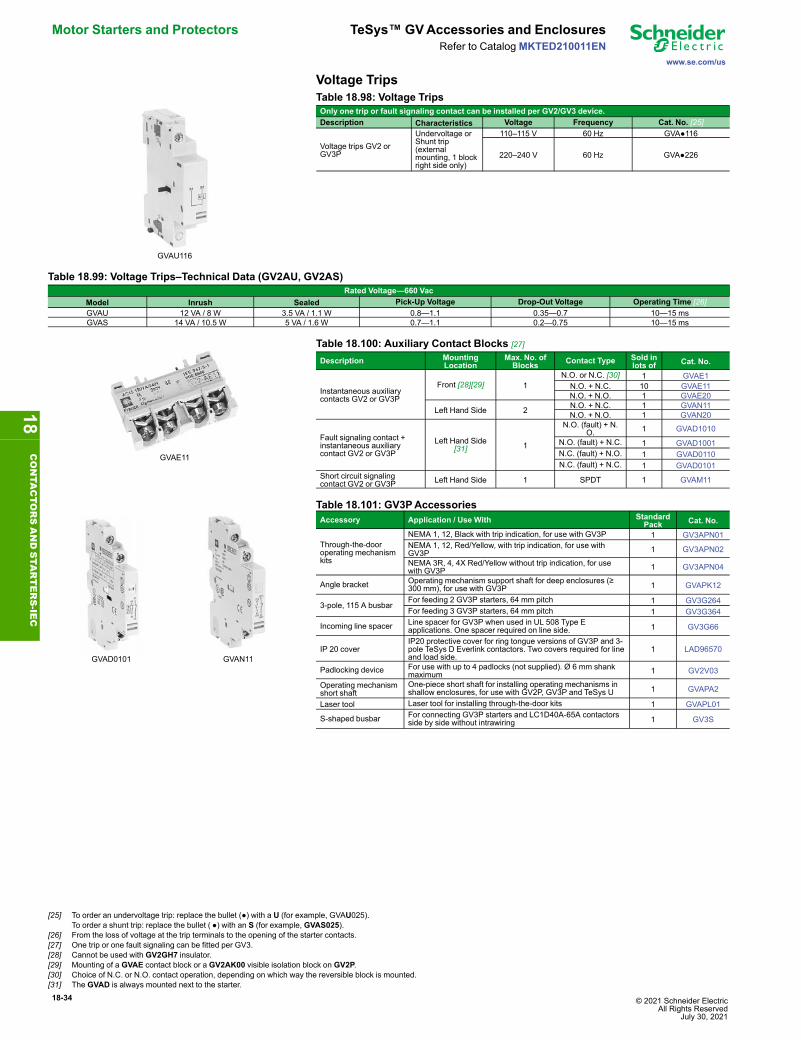
18-34 © 2021 Schneider Electric All Rights Reserved
July 30, 2021
Motor Starters and Protectors TeSys™ GVAccessories and Enclosures
www.se.com/us
Refer to CatalogMKTED210011EN
Voltage Trips
GVAU116
Table 18.98: Voltage TripsOnly one trip or fault signaling contact can be installed per GV2/GV3 device.Description Characteristics Voltage Frequency Cat. No. [25]
Voltage trips GV2 orGV3P
Undervoltage orShunt trip(externalmounting, 1 blockright side only)
110–115 V 60 Hz GVA●116
220–240 V 60 Hz GVA●226
Table 18.99: Voltage Trips–Technical Data (GV2AU, GV2AS)Rated Voltage—660 Vac
Model Inrush Sealed Pick-Up Voltage Drop-Out Voltage Operating Time [26]GVAU 12 VA / 8 W 3.5 VA / 1.1 W 0.8—1.1 0.35—0.7 10—15 msGVAS 14 VA / 10.5 W 5 VA / 1.6 W 0.7—1.1 0.2—0.75 10—15 ms
GVAE11
Table 18.100: Auxiliary Contact Blocks [27]
Description MountingLocation
Max. No. ofBlocks Contact Type Sold in
lots of Cat. No.
Instantaneous auxiliarycontacts GV2 or GV3P
Front [28][29] 1N.O. or N.C. [30] 1 GVAE1N.O. + N.C. 10 GVAE11N.O. + N.O. 1 GVAE20
Left Hand Side 2 N.O. + N.C. 1 GVAN11N.O. + N.O. 1 GVAN20
Fault signaling contact +instantaneous auxiliarycontact GV2 or GV3P
Left Hand Side[31] 1
N.O. (fault) + N.O. 1 GVAD1010
N.O. (fault) + N.C. 1 GVAD1001N.C. (fault) + N.O. 1 GVAD0110N.C. (fault) + N.C. 1 GVAD0101
Short circuit signalingcontact GV2 or GV3P Left Hand Side 1 SPDT 1 GVAM11
GVAD0101 GVAN11
Table 18.101: GV3PAccessoriesAccessory Application / Use With Standard
Pack Cat. No.
Through-the-dooroperating mechanismkits
NEMA 1, 12, Black with trip indication, for use with GV3P 1 GV3APN01NEMA 1, 12, Red/Yellow, with trip indication, for use withGV3P 1 GV3APN02
NEMA 3R, 4, 4X Red/Yellow without trip indication, for usewith GV3P 1 GV3APN04
Angle bracket Operating mechanism support shaft for deep enclosures (≥300 mm), for use with GV3P 1 GVAPK12
3-pole, 115 A busbarFor feeding 2 GV3P starters, 64 mm pitch 1 GV3G264For feeding 3 GV3P starters, 64 mm pitch 1 GV3G364
Incoming line spacer Line spacer for GV3P when used in UL 508 Type Eapplications. One spacer required on line side. 1 GV3G66
IP 20 coverIP20 protective cover for ring tongue versions of GV3P and 3-pole TeSys D Everlink contactors. Two covers required for lineand load side.
1 LAD96570
Padlocking device For use with up to 4 padlocks (not supplied). Ø 6 mm shankmaximum 1 GV2V03
Operating mechanismshort shaft
One-piece short shaft for installing operating mechanisms inshallow enclosures, for use with GV2P, GV3P and TeSys U 1 GVAPA2
Laser tool Laser tool for installing through-the-door kits 1 GVAPL01
S-shaped busbar For connecting GV3P starters and LC1D40A-65A contactorsside by side without intrawiring 1 GV3S
18CONTA
CTORSANDSTA
RTERS-IE
C
[25] To order an undervoltage trip: replace the bullet (●) with a U (for example, GVAU025).To order a shunt trip: replace the bullet ( ●) with an S (for example, GVAS025).
[26] From the loss of voltage at the trip terminals to the opening of the starter contacts.[27] One trip or one fault signaling can be fitted per GV3.[28] Cannot be used with GV2GH7 insulator.[29] Mounting of a GVAE contact block or a GV2AK00 visible isolation block on GV2P.[30] Choice of N.C. or N.O. contact operation, depending on which way the reversible block is mounted.[31] The GVAD is always mounted next to the starter.

© 2021 Schneider Electric All Rights ReservedJuly 30, 2021
18-35
www.se.com/us
TeSys™ GVAccessories and Enclosures Motor Starters and ProtectorsRefer to Catalog MKTED210011EN
Common Accessories for BV4, GV4, GV5 and GV6Common Accessories BV4 Reference GV4 Reference GV5 Reference GV6 ReferenceAuxiliary contacts OF or SDOpen/Closed Status GV4AE11 GV4AE11 GV7AE11 GV7AE11Trip Alarm — — — —Open/Closed Status — Low Level — — GV7AB11 GV7AB11Fault signalization modulesFor GV4PB, SDx module mounts externally on the right side, and provides pre-trip alarm andfault signalization
• SDT95% overload alarm: thermal image of the motor is greater than 95 % of the permissibletemperature rise.
• SDTxxs overload alarm: circuit breaker will trip in xx seconds with the same load. xx isadjustable between 10 to 40 seconds (default 20 seconds) on the circuit breaker itselfthrough NFC or a computer with EcoStruxure Power Commission software and an interfacemodule (TRV00911).
• SDTAM overload alarm just before tripping: in the event of a phase unbalance, overload, oron a jam fault, this output is activated to open the contactor and avoid circuit breakertripping. In that case, contact can be manually or automatically reseted after an adjustablecooling time from 1 to 15 minutes. If after a 400 ms delay the motor is not stopped, thecircuit breaker will trip.
• SDToverload trip indication: circuit breaker has tripped due to an overload fault.
• SDJAM jam trip indication: circuit breaker has tripped due to a jam fault.
• SDUNB phase unbalance trip indication: circuit breaker has tripped due to an unbalancefault.
• SDLS long start trip indication: circuit breaker has tripped due to a long start fault.
• SDGF ground-fault trip indication: circuit breaker has tripped due to a ground-fault.For GV5PB & GV6PB, SDx module mounts internally, and includesa pre-trip contact (400 msprior to trip) that can be use to open the contactor, as well as a contact that indicates overloadtrip of the circuit-breaker.
— GV4ADM1111 LV429424 (1) LV429424 (1)
Instantaneous voltage release
Undervoltage Release (Mn)
24 V 50/60 Hz GV4AU027 GV4AU027 S29404 S2940424 Vdc — — — —48 V 50/60 Hz–48 Vdc GV4AU057 GV4AU057 GV7AU055 GV7AU055110–130 V 50/60 Hz–125 Vdc GV4AU137 GV4AU137 GV7AU107 GV7AU107208–240 V 50/60 Hz GV4AU247 GV4AU247 GV7AU207 GV7AU207277 V 60 Hz GV4AU286 GV4AU286 — —380–415 V 50 Hz GV4AU415 GV4AU415 GV7AU387 GV7AU387440–480 V 60 Hz GV4AU486 GV4AU486 — —525–600 V 60 Hz — — S29409 S29409
Shunt Trip (Mx)
24 V 50/60 Hz GV4AS027 GV4AS027 S29384 S2938424 Vdc — — — —48 V 50/60 Hz–48 Vdc GV4AS057 GV4AS057 GV7AS055 GV7AS055110–130 V 50/60 Hz–125 Vdc GV4AS137 GV4AS137 GV7AS107 GV7AS107208–240 V 50/60 Hz GV4AS287 GV4AS287 GV7AS207 GV7AS207277 V 60 Hz — — — —380–415 V 50 Hz–440–480 V 60 Hz GV4AS487 GV4AS487 GV7AS387 GV7AS387525–600 V 60 Hz — — S29389 S29389
Rotary handles
DirectWith black handle on black font GV4ADN01 GV4ADN01 GV5AP03 GV6AP03With red handle on yellow font GV4ADN02 GV4ADN02 GV7AP04 LV432599
Front extended IP54With black handle on black font GV4APN01 GV4APN01 GV7AP01 (2) LV432598 (2)With red handle on yellow font GV4APN02 GV4APN02 GV7AP02 (2) LV432600 (2)
Front extended IP65 With red handle on yellow font GV4APN04 GV4APN04 — —
LateralWith black handle on black font LV426935 LV426935 — —With red handle on yellow font LV426936 LV426936 — —
Open door shaft operator LV426937 LV426937 — —Laser alignment tool to aid in aligning hole on door with rotary mechanism GVAPL01 GVAPL01 GVAPL01 GVAPL01
18CONTA
CTORSANDSTA
RTERS-IEC

18-36 © 2021 Schneider Electric All Rights Reserved
July 30, 2021
Motor Starters and Protectors TeSys™ D Enclosed Starters
www.se.com/us
Refer to CatalogMKTED210011EN
Additional BV4 and GV4 AccessoriesAccessory BV4 Reference GV4 ReferenceCabling AccessoriesEverLink Connector (replacement) LAD96565 LAD96565Large Spacing Cover for EverLink Connector (replacement) GV4G66 —Crimp Lug Connector + Screws GV4LUG GV4LUGTransparent Terminal Shield for Crimped Lug Connector LAD96590 LAD96590Interphase Barriers LV426920 LV426920One Time Torque Limiters, Green—9 N.m (set of 6) LV426990 LV426990One Time Torque Limiters, Yellow—5 N.m (set of 6) LV426992 LV426992Locking AccessoriesRemovable Toggle Locking Device for 1 to 3 Padlocks 29370 —Bag of 6 Leads + 6 Sealing Accessories LV429375 —Programming ToolsPocket Battery—Allows changes to settings on the GV4PB when not powered by the line voltage — LV434206GV4PB cord for USB Maintenance Interface — TRV00917EcoStruxure Power Commission app — Free download
Additional GV5 and GV6 AccessoriesAccessory GV5PB150.. Reference GV5PB250.. Reference GV6PB.. ReferenceCabling Accessories
Mechanical lug kit (set of 3)
14–10 AWG (2.5–6mm2 )—Al/Cu AL150HD — —14–2/0 AWG (2.5—70mm)—Cu CU150HD1 — —4–4/0 AWG (25–95mm2 )—Al/Cu — AL175JD —3/0–350 kcmil AWG (95–185mm2 )—Al/Cu — AL250JD —1/0 AWG–300 kcmil (50–185mm2 )—Al/Cu — CU250JD1 —2 AWG–500 kcmil (35–240mm2)—Al
— — AL400L61K32 AWG–600 kcmil (35–300mm2)—Cu2 AWG–600 kcmil (35–300mm2)—Cu — — CU400L61K32/0 AWG–500 kcmil (70–240 mm2)—Al/Cu — — AL600LS52K32/0 AWG–500 kcmil (70–240mm2)—Cu — — CU600LS52K33/0 AWG–500 kcmil (95–240)—Al/Cu — — AL600LF52K33/0 AWG–500 kcmil (95–240)—Cu — — CU600LF52K3
Terminal Nut Insert kit/Bus Bar Connections1/4–20 Tap (set of 3) S37444 S37445 —M10 x 25 terminal screws and washers for oneside (set of 4) — — S36967
Terminal ShieldShort Terminal Shield S37447 S37448 LTSS3PMedium Terminal Shield — — LTSM3PLong Terminal Shield — — LTSL3P
Phase Barriers Phase Barriers (set of 6) S29329 S29329 32570Locking & Other Accessories
Door LockRemovable Door lock (lock off only) S29370 S29370 S29370Fixed Door lock (on or off) S29371 S29371 S32631
Toggle Extension Fixed (set of 5) S29313 S29313 S432553
18CONTA
CTORSANDSTA
RTERS-IE
C

© 2021 Schneider Electric All Rights ReservedJuly 30, 2021
18-37
www.se.com/us
TeSys™ D Enclosed Combination Starters Motor Starters and ProtectorsRefer to Catalog MKTED210011EN
Enclosed TeSys™ D Starters
LE1D093A62OB70
TeSys D enclosed full-voltage starters are available in Type 1 and Type 12/3Renclosures. The enclosed TeSys D offer accepts standard TeSys D accessories and allInsta-Kits control units and control power transformer kits. For additional sizes,combinations and accessory options, see Catalog 8100CT1901. Check with local salesoffice for availability.
Table 18.102: Insta-Kits for Enclosed Full Voltage Non-Reversing Starters[32]Max. Horsepower Ratings Auxiliary Contacts On
Each Contactor Current Ratingof Contactor
Catalog Number[33]Single-Phase Three-Phase
120 V 240 V 208 V 230 V 460 V 575 V N.O. N.C. Type 1 Type 12/3R1/3 1 2 2 5 7.5 1 1 9 LE1D093A62O•••• LE1D093A72O••••1/2 2 3 3 7.5 10 1 1 12 LE1D123A62O•••• LE1D123A72O••••1 3 5 5 10 15 1 1 18 LE1D183A62O•••• LE1D183A72O••••2 3 5 7.5 15 20 1 1 25 LE1D253A62O•••• LE1D253A72O••••2 5 7.5 10 20 25 1 1 32 LE1D323A62O•••• LE1D323A72O••••3 5 10 10 30 30 1 1 40 LE1D403A62O•••• LE1D403A72O••••3 7.5 15 15 40 40 1 1 50 LE1D503A62O•••• LE1D503A72O••••5 10 20 20 40 50 1 1 65 LE1D653A62O•••• LE1D653A72O••••
Table 18.103: Voltage Codes for Enclosed StartersPrimary Voltage 120 208 240
Code G7 L7 U7TeSys D dimensions: page 18-55
Insta-Kits Selection
L1 L2
PL
M
OFF ON
1 2 3 4 A B
OLR
95 96
X1 X2
PL61 62 X1 X2
L1 L2
M
HAND AUTO
OFF
PLX1 X2
3 4
3 4
95 96
61 62PL
X1 X2
Remote by Customer Connection
L1 L2START
STOP1 2 A B3 4
M95 96
13 14
OLR
From top to bottom: Start/Stop, On - Off Selector Switch, HOASelector Switch
With the use of Insta-Kits, only one operator scheme is allowed. For additional accessorykits and options, see Catalog 8100CT1901. Check with local sales office for availability.
L1 L2 L3
M
98
97
B
A
96
95
13
14
T1 T2 T3D-Line AC Magnetic Starter, 2–3 Pole
18CONTA
CTORSANDSTA
RTERS-IEC
[32] See Table 18.25 TeSys D Overload Relays—Ambient Compensated, Bimetallic, Direct Mounting, page 18-12 for field installable overload relays.[33] To obtain a single phase non-reversing starter, change prefix LE1 to LES. (e.g., LE1D093A62O•••• becomes LESD093A62O••••). Price remains unchanged.
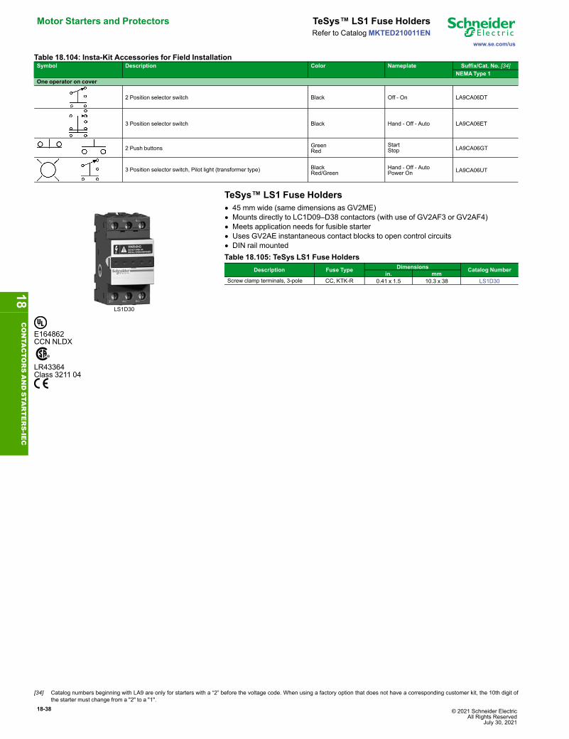
18-38 © 2021 Schneider Electric All Rights Reserved
July 30, 2021
Motor Starters and Protectors TeSys™ LS1 Fuse Holders
www.se.com/us
Refer to CatalogMKTED210011EN
Table 18.104: Insta-Kit Accessories for Field InstallationSymbol Description Color Nameplate Suffix/Cat. No. [34]
NEMAType 1One operator on cover
2 Position selector switch Black Off - On LA9CA06DT
3 Position selector switch Black Hand - Off - Auto LA9CA06ET
2 Push buttons GreenRed
StartStop LA9CA06GT
3 Position selector switch, Pilot light (transformer type) BlackRed/Green
Hand - Off - AutoPower On LA9CA06UT
TeSys™ LS1 Fuse Holders
LS1D30
• 45 mm wide (same dimensions as GV2ME)• Mounts directly to LC1D09–D38 contactors (with use of GV2AF3 or GV2AF4)• Meets application needs for fusible starter• Uses GV2AE instantaneous contact blocks to open control circuits• DIN rail mountedTable 18.105: TeSys LS1 Fuse Holders
Description Fuse Type Dimensions Catalog Numberin. mm
Screw clamp terminals, 3-pole CC, KTK-R 0.41 x 1.5 10.3 x 38 LS1D30
E164862CCN NLDX
LR43364Class 3211 04
18CONTA
CTORSANDSTA
RTERS-IE
C
[34] Catalog numbers beginning with LA9 are only for starters with a “2” before the voltage code. When using a factory option that does not have a corresponding customer kit, the 10th digit ofthe starter must change from a "2" to a "1".
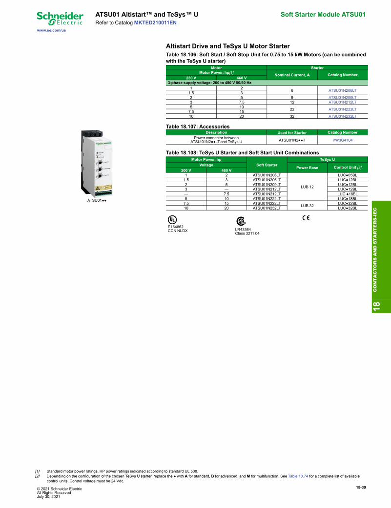
© 2021 Schneider Electric All Rights ReservedJuly 30, 2021
18-39
www.se.com/us
ATSU01 Altistart™ and TeSys™ U Soft Starter Module ATSU01Refer to Catalog MKTED210011EN
Altistart Drive and TeSys U Motor StarterTable 18.106: Soft Start / Soft Stop Unit for 0.75 to 15 kW Motors (can be combinedwith the TeSys U starter)
Motor StarterMotor Power, hp[1] Nominal Current, A Catalog Number
230 V 460 V3-phase supply voltage: 200 to 480 V 50/60 Hz
1 2 6 ATSU01N206LT1.5 32 5 9 ATSU01N209LT3 7.5 12 ATSU01N212LT5 10 22 ATSU01N222LT7.5 1510 20 32 ATSU01N232LT
ATSU01●●
Table 18.107: AccessoriesDescription Used for Starter Catalog Number
Power connector betweenATSU 01N2●●LTand TeSys U ATSU01N2●●T VW3G4104
Table 18.108: TeSys U Starter and Soft Start Unit CombinationsMotor Power, hp
Soft StarterTeSys U
VoltagePower Base Control Unit [2]
200 V 460 V1 2 ATSU01N206LT
LUB 12
LUC●05BL1.5 3 ATSU01N206LT LUC●12BL2 5 ATSU01N209LT LUC●12BL3 — ATSU01N212LT LUC●12BL— 7.5 ATSU01N212LT LUC ●18BL5 10 ATSU01N222LT LUC●18BL7.5 15 ATSU01N222LT LUB 32 LUC●32BL10 20 ATSU01N232LT LUC●32BL
E164862CCN NLDX LR43364
Class 3211 04
18CONTA
CTORSANDSTA
RTERS-IEC
[1] Standard motor power ratings, HP power ratings indicated according to standard UL 508.[2] Depending on the configuration of the chosen TeSys U starter, replace the ● with A for standard, B for advanced, andM for multifunction. See Table 18.74 for a complete list of available
control units. Control voltage must be 24 Vdc.

18-40 © 2021 Schneider Electric All Rights Reserved
July 30, 2021
Replacement Parts TeSys™ D AC Coils
www.se.com/us
Refer to CatalogMKTED210011EN
TeSys™ D—AC Coils
LX1D2
Table 18.109: For LC1D09–D38, LC1DT20–DT40 Contactors and CAD RelaysRated Nominal Voltage Catalog Number, 50/60 Hz24 LXD1B7120 LXD1G7208 LXD1LE7230/240 LXD1U7277 LXD1W7Specifications 50/60 HzAverage consumption- Inrush (inductance 0.75)- Sealed (inductance 0.3)
70 VA7 VA
Operating range@ 60o C 80–110% of nominal @ 50 Hz,85–110% of nominal @ 60 Hz
TeSys™ D—AC Coils
LX1D6
Table 18.110: For Old D2 Style LC1D40, D50, D65, D80, and D95; For TeSys DLC1D40A, D50A, D65A, DT60A, and DT80A; For TeSys D LC1D115 and D150
For TeSys D LC1D40A, D50A, D65A, DT60A, DT80ARated
Nominal Voltage, VCatalog Number
50/60 HzFor TeSys D LC1D40A, D50A, D65A, DT60A, DT80A
24 LXD3B7120 LXD3G7[1]208 LXD3LE7[1]240 LXD3U7480 LXD3T7
Specification 50/60 HzAverage consumption-inrush(inductance 0.3)
140 VA (Inductance: 0.9)
-sealed(inductance 0.3)
7.5 VA(Inductance: 0.9)
Operating range
at θ ≤ 55 °C / 131 °F 80–115% ofnominal voltage
For TeSys D LC1D115, D150 24 LX1D8B7120 LX1D8G7208 LX1D8L7240 LX1D8U7277 LX1D8W7480 LX1D8T7
Specification 50/60 HzAverage consumption-inrush(inductance 0.8)
350 VA (Inductance: 0.9)
-sealed(inductance 0.3)
18 VA(Inductance: 0.9)
Operating range
at θ ≤ 55 °C / 131 °F 80–115% ofnominal voltage
Table 18.111: TeSys™ F—AC Coils (For LC1F115, F150, F185, F225, F265, F330, F400, F500, F630, F780, F800, and F1400–F2100)Contactor F115-F150 F185-F225 F265-F330 F400 F500 F630 F780[2] F800[3] F1400-F2100[3]Coil Part Number AC 50/60 Hz
120 V LX9FF127 LX9FG127 LX1FH1272 LX1FJ127 LX1FK127 LX1FL110 LX1FX110 LX4F8FW LX1FK070[4]240 V LX9FF220 LX9FG220 LX1FH2402 LX1FJ240 LX1FK240 LX1FL220 LX1FX220 LX4F8MW LX1FK127480 V LX9FF500 LX9FG500 LX1FH5002 LX1FJ500 LX1FK500 LX1FL415 LX1FX415 — LX1FK240
Coil Part Number DC24 V LX4FF024 LX4FG024 LX4FH024 — — — — — —
18CONTA
CTORSANDSTA
RTERS-IE
C
[1] 60 Hz only[2] LC1F780 contactors operate with 2 coils as a set. The LX1FX• part number includes both coils.[3] Also requires rectifier DR5TE4U for 110–240 V coils.[4] Order 2 coils and connect them in series.

© 2021 Schneider Electric All Rights ReservedJuly 30, 2021
18-41
www.se.com/us
TeSys™ F Contactors Wiring SystemsRefer to Catalog MKTED210011EN
TeSys™ F Contact Kits, Arc Chambers
LA5FG431
Table 18.112: Replacement Contact Sets [5]
For use on contactors Number of Poles Catalog Number
Three-pole
LC1F115, F150 3 poles LA5FF431LC1F185, F225 3 poles LA5FG431LC1F265 3 poles LA5FH431LC1F330, F400 3 poles LA5F400803LC1F500 3 poles LA5F500803LC1F630 3 poles LA5F630803LC1F780 1 pole LA5F780801 [6]LC1F800 3 poles LA5F800803
TeSys F contactors: page 18-14 and page 18-14TeSys F overload relay accessories: page 18-24TeSys F replacement coils and parts: page 18-40, and page 18-40TeSys F dimensions: page 18-45, page 18-54
TeSys™ AK5 Panel Busbar SystemThe AK5 pre-fabricated bus bar system provides a quick and easy method of mountingcontrol devices. All components are finger safe, UL Listed, CSA approved and CEmarked. Although the AK5 system can be screw mounted onto any type of support, itmust be mounted on the AM1DL201 DIN rail when component mounting platesincorporating a tap-off are used. When using tap-offs, the nominal operating current ofthe bus bar (160 A @ 35°) must not be exceeded. Approvals include IEC 439, UL, CSA,DNVand LROS.
AK5JB busbar
Table 18.113: 160 A, 3-Phase Busbar SystemMaximum number of mounting plates
Length Catalog NumberTap-off Standard WidthPlate Extension Plate
1.42 in. 36 mm 2.13 in. 54 mm 2.80 in. 71 mm in. mm15 10 5 26.05 668 AK5JB14624 16 8 38.69 992 AK5JB149
AK5PA231
Table 18.114: Mounting Plate Tap-off(plugs into busbar mounted on AM1DL201 DIN rail)
Width ThermalCurrent Amperes Application Catalog Number
in. mm2.13 54 25 A GV2 with LUS or LUB 12 and 32 AK5PA2312.13 54 25 A contactor AK5PA232
AK5PA232S
Table 18.115: Bus Tap-off(plugs into busbar for wiring to a separately mounted device)
Width ThermalCurrent (A)
Length of Leads Catalog Numberin. mm in. mm1.42 36 32 A 9.84 250 AK5PC331.42 36 32 A 39.37 1000 AK5PC33L
AK5PC33
AM1DL201
Table 18.116: Mounting Rail (must be used for mounting plates with tap-offs)Description Depth Length Catalog
Numbermm mm75 mm Omega Rail 15 2000 AM1DL201
File E161251CCN NMTR
File LR 89150Class 6228-01
18CONTA
CTORSANDSTA
RTERS-IEC
[5] Supplied per pole are: 2 fixed contacts, 1 moving contact, 2 deflectors, 1 backplate, mounting screws and washers.[6] Two identical components per pole are supplied.
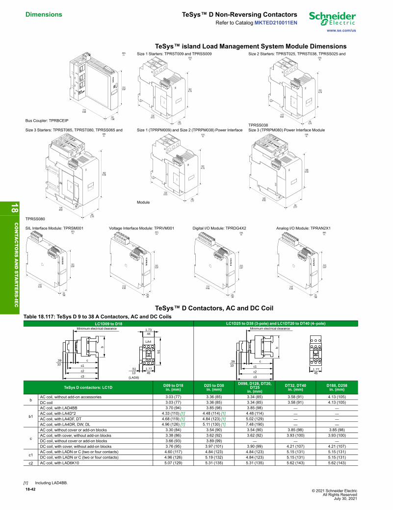
18-42 © 2021 Schneider Electric All Rights Reserved
July 30, 2021
Dimensions TeSys™ D Non-Reversing Contactors
www.se.com/us
Refer to CatalogMKTED210011EN
TeSys™ island Load Management System Module Dimensions
Bus Coupler: TPRBCEIP
Size 1 Starters: TPRST009 and TPRSS009 Size 2 Starters: TPRST025, TPRST038, TPRSS025 and
TPRSS038Size 3 Starters: TPRST065, TPRST080, TPRSS065 and
TPRSS080
Size 1 (TPRPM009) and Size 2 (TPRPM038) Power Interface
Module
Size 3 (TPRPM080) Power Interface Module
SIL Interface Module: TPRSM001 Voltage Interface Module: TPRVM001 Digital I/O Module: TPRDG4X2 Analog I/O Module: TPRAN2X1
TeSys™ D Contactors, AC and DC CoilTable 18.117: TeSys D 9 to 38 A Contactors, AC and DC Coils
LC1D09 to D18 LC1D25 to D38 (3-pole) and LC1DT20 to DT40 (4–pole)
b
c
c1
c2
c3
1.77
(LAD8)
b1
1.73
LA4
.3910
44
45.5113
Minimum electrical clearance
b
1.77
c.3910 c1
c2
c345
Minimum electrical clearance
TeSys D contactors: LC1D D09 to D18in. (mm)
D25 to D38in. (mm)
D098, D128, DT20,DT25
in. (mm)DT32, DT40in. (mm)
D188, D258in. (mm)
bAC coil, without add-on accessories 3.03 (77) 3.36 (85) 3.34 (85) 3.58 (91) 4.13 (105)DC coil 3.03 (77) 3.36 (85) 3.34 (85) 3.58 (91) 4.13 (105)
b1
AC coil, with LAD4BB 3.70 (94) 3.85 (98) 3.85 (98) — —AC coil, with LA4D*2 4.33 (110) [1] 4.48 (114) [1] 4.48 (114) — —AC coil, with LA4DF, DT 4.68 (119) [1] 4.84 (123) [1] 5.02 (129) — —AC coil, with LA4DR, DW, DL 4.96 (126) [1] 5.11 (130) [1] 7.48 (190) — —
c
AC coil, without cover or add-on blocks 3.30 (84) 3.54 (90) 3.54 (90) 3.85 (98) 3.85 (98)AC coil, with cover, without add-on blocks 3.38 (86) 3.62 (92) 3.62 (92) 3.93 (100) 3.93 (100)DC coil, without cover or add-on blocks 3.66 (93) 3.89 (99) — — —DC coil, with cover, without add-on blocks 3.76 (95) 3.97 (101) 3.90 (99) 4.21 (107) 4.21 (107)
c1AC coil, with LADN or C (two or four contacts) 4.60 (117) 4.84 (123) 4.84 (123) 5.15 (131) 5.15 (131)DC coil, with LADN or C (two or four contacts) 4.96 (126) 5.19 (132) 4.84 (123) 5.15 (131) 5.15 (131)
c2 AC coil, with LAD6K10 5.07 (129) 5.31 (135) 5.31 (135) 5.62 (143) 5.62 (143)
1013.97
501.96
mmin.
1144.48
1214.76
1154.53
451.77
mmin.
1214.76
1154.53
451.77
mmin.
1626.38
mmin.
1254.92
552.16
1214.76
1154.53
451.77
mmin.
1365.34
1254.92
552.17
mmin.
1013.97
1144.48
25.98
mmin.
1013.97
1144.48
25.98
mmin.
1013.97
1144.48
25.98
mmin.
1013.97
1144.48
25.98
mmin.
18CONTA
CTORSANDSTA
RTERS-IE
C
[1] Including LAD4BB.

© 2021 Schneider Electric All Rights ReservedJuly 30, 2021
18-43
www.se.com/us
TeSys™ D Non-Reversing Contactors DimensionsRefer to Catalog MKTED210011EN
Table 18.117 TeSys D 9 to 38 A Contactors, AC and DC Coils (cont'd.)LC1D09 to D18 LC1D25 to D38 (3-pole) and LC1DT20 to DT40 (4–pole)
b
c
c1
c2
c3
1.77
(LAD8)
b1
1.73
LA4
.3910
44
45.5113
Minimum electrical clearance
b
1.77
c.3910 c1
c2
c345
Minimum electrical clearance
TeSys D contactors: LC1D D09 to D18in. (mm)
D25 to D38in. (mm)
D098, D128, DT20,DT25
in. (mm)DT32, DT40in. (mm)
D188, D258in. (mm)
DC coil, with LAD6K10 5.43 (138) 5.66 (144) 5.31 (135) 5.62 (143) 5.62 (143)
c3
AC coil, with LADT, R, S 5.39 (137) 5.62 (143) 5.62 (143) 5.94 (151) 5.94 (151)AC coil, with LADT, R, S and sealing cover 5.55 (141) 5.78 (147) 5.78 (147) 6.10 (155) 6.10 (155)DC coil with LADT, R, S 5.76 (146) 5.98 (152) 5.62 (143) 5.94 (151) 5.94 (151)DC coil with LADT, R, S and sealing cover 5.90 (150) 6.14 (156) 5.78 (147) 6.10 (155) 6.10 (155)
Table 18.118: TeSys D 40 A to 65 A, AC and DC coilLC1 D40A–D65A (3P), LC1 DT60A–DT80A (4P) AC OR DC LC1
D40A–D65A DT60A–DT80Ain. (mm) in. (mm)
LAD 4BB3
117
122
a(LAD 8N) (LAD 8N)
c1
c2
c3
LA4 DpB
LA4 DpB
LAD 4BB3
b1
12c
5 (125)
Min. electrical clearance
DF
5691
84.e
ps
.47
4.80
4.6
5 (125)
a 2.17 (55) 2.76 (70)
b1
with LA4 D●2 — —with LA4 DB3 or LAD 4BB3 5.35 (136) —with LA4 DF, DT 6.18 (157) —with LA4 DM, DW, DL 6.54 (166) —
cwithout cover or add-on blocks 4.65 (118) 4.65 (118)with cover, without add-on blocks 4.72 (120) 4.72 (120)
c1with LADN (1 contact) — —with LADN or C (2 or 4 contacts) 5.91 (150) 5.91 (150)
c2 with LAD 6K10 or LA6 DK 6.42 (163) 6.42 (163)
c3
with LADT, R, S 6.73 (171) 6.73 (171)
with LADT, R, S and sealing cover 6.89 (175) 6.89 (175)
Table 18.119: TeSys D80 and D95 AC CoilLC1D80 and D95 (3P), LP1 D80004 and D80008 (4P) LC1
D80 D95 D80004 D80008in. (mm) in. (mm) in. (mm) in. (mm)
5 (125)(LAD 8) (LAD 8)
5 (1
27)
b1
a 5 (125)
4432LA4
c12 c1
c2c3
1.26 1.73
.47
a 3.35 (85) 3.35 (85) 3.78 (96) 3.78 (96)
b1
with LA4 D●2 5.31 (135) 5.31 (135) 5.31 (135) 5.31 (135)with LA4 DB3 or LAD 4BB3 5.31 (135) — — —with LA4 DF, DT 5.59 (142) 5.59 (142) 5.59 (142) 5.59 (142)with LA4 DM, DW, DL 5.90 (150) 5.90 (150) 5.90 (150) 5.90 (150)
cwithout cover or add-on blocks 4.92 (125) 4.92 (125) 4.92 (125) 5.51 (140)with cover, without add-on blocks 5.12 (130) 5.12 (130) — —
c1with LADN (1 contact) 5.90 (150) 5.90 (150) 5.90 (150) 5.90 (150)with LADN or C (2 or 4 contacts) 6.22 (158) 6.22 (158) 6.22 (158) 6.22 (158)
c2 with LAD 6K10 or LA6 DK 6.69 (170) 6.69 (170) 6.69 (170) 6.69 (170)
c3
with LADT, R, S 7 (178) 7 (178) 7 (178) 7 (178)
with LADT, R, S and sealing cover 7.16 (182) 7.16 (182) 7.16 (182) 7.16 (182)
18CONTA
CTORSANDSTA
RTERS-IEC

18-44 © 2021 Schneider Electric All Rights Reserved
July 30, 2021
Dimensions TeSys™ D Non-Reversing Contactors
www.se.com/us
Refer to CatalogMKTED210011EN
TeSys™ D Contactors, DC CoilTable 18.120: DC CoilLC1D80, D95 (3P), LP1D80004, D80008 (4P) LC1
D80 and D95 D80004 D80008in. (mm) in. (mm) in. (mm)
5 (125)(LAD 8) (LAD 8)
5 (1
27)
b1
a 5 (125)
4432LA4
c12 c1
c2c3
Minimum electrical clearance
1.261.73
.47
a 3.35 (85) 3.78 (96) 3.78 (96)
b1with LAD 4BB3 — — —with LA4 DF, DT — — —
cwithout cover or add-on blocks 7.13 (181) 7.13 (181) 7.72 (196)with cover, without add-on blocks 7.32 (186) — —
c1with LAD N (1 contact) 8.03 (204) 8.03 (204) 8.03 (204)
with LAD N or C (2 or 4 contacts) 8.27 (210) 8.27 (210) 8.27 (210)c2 with LA6 DK10 8.70 (221) 8.70 (221) 8.70 (221)
c3with LAD T, R, S 9.01 (229) 9.01 (229) 9.01 (229)
with LAD T, R, S and sealingcover 9.17 (233) 9.17 (233) 9.17 (233)
LC1D115, D150 (3P), LC1D115004 (4P), AC and DC CoilsPanel mounted with 1/4” screws LC1
D115, D150 D115004 D1150046in. (mm) in. (mm) in. (mm)
158
c ac1c2c3
b1LAD 8
LA4
10
Min. electrical clearance
6.22
.39
With 2 or 4 contacts.+ 4 mm with sealing cover.
a 4.72 (120) 5.91 (150) 6.10 (155)
b1
with LA4DA2 6.85 (174) 6.85 (174) 6.85 (174)with LA4DF, DT 7.28 (185) 7.28 (185) 7.28 (185)with LA4DM, DL 7.40 (188) 7.40 (188) 7.40 (188)with LA4DW 5.20 (132) 5.20 (132) 4.53 (115)
cwithout cover or add-on blocks 5.35 (136) — —with cover, without add-on blocks 5.35 (136) — —
c1 with LAD N or C (2 or 4 contacts) 5.91 (150) 5.91 (150) 5.91 (150)c2 with LA6DK20 6.10 (155) 6.10 (155) 6.10 (155)
c3with LAD T, R, S 6.61 (168) 6.61 (168) 6.61 (168)
with LADT, R, S and sealing cover 6.77 (172) 6.77 (172) 6.77 (172)
18CONTA
CTORSANDSTA
RTERS-IE
C

© 2021 Schneider Electric All Rights ReservedJuly 30, 2021
18-45
www.se.com/us
TeSys™ F Non-Reversing Contactors DimensionsRefer to Catalog MKTED210011EN
TeSys™ F Contactors, DimensionsAll dimensions shown in mm.To convert to inches, divide by 25.4.
LC1F115 to F330
Lc
b b2
==
X1
X1
(1) Protective cover Type LA9F70•
(1)
S s1
Q P P Q1
a f
M
(2)
(2) Optimal terminal shroud
Z
= =G1
G Y
J J1 b1=
=
Table 18.121: LC1F115–F330 Dimensions
LC1F115 F150 F185 F225 F265 F330
3-Pole 4-Pole 3-Pole 4-Pole 3-Pole
4-Pole
3-Pole
4-Pole
3-Pole
4-Pole
3-Pole
4-Pole
a 163.5 200.5 163.5 200.5 168.5 208.5 168.5 208.5 201.5 243.5 213 261b 162 162 170 170 174 174 197 197 203 203 206 206b1 137 137 137 137 137 137 137 137 145 145 145 145b2 265 265 301 301 305 305 364 364 370 370 375 375c 165 [2] 165 [2] 165 [2] 165 [2] 176 176 181 181 207 207 219 219f 131 131 131 131 130 130 130 130 147 147 147 147G 106 143 106 143 111 151 111 151 142 190 154.5 202.5G1 80 80 80 80 80 80 80 80 96 96 96 96J 106 106 106 106 106 106 106 106 106 106 106 106J1 120 120 120 120 120 120 120 120 120 120 120 120L 107 107 107 107 113.5 113.5 113.5 113.5 141 141 145 145M 147 147 150 150 154 154 172 172 178 178 181 181P 37 37 40 40 40 40 48 48 48 48 48 48Q 29.5 29.5 26.5 26 29 29 21 17 39 34 43 43Q1 60 60 57.5 55.5 59.5 59.5 51.5 47.5 66.5 66.5 74 74S 15 15 20 20 20 20 25 25 25 25 25 25S1 27 27 34 34 34 34 44.5 44.5 38 38 44.5 44.5Y 44 44 44 44 44 44 44 44 38 38 38 38Z 13.5 13.5 13.5 13.5 13.5 13.5 13.5 13.5 21.5 21.5 20.5 20.5
f = minimum distance required for coil removal.
Table 18.122: LC1F115–F330 Voltage200 to 500 V 600 to 1000 V
LC1F115, F150 10 15LC1F185 10 15
LC1F225, F265 10 15LC1F330 10 15
X1: Minimum clearance according to the operational voltage and the breaking capacity.
LC1F400 to F500
2.2056
X1c
L
8.23
209 b b2
==
(1)
(1) Protective cover
S 1.4938
M10 X 30 dia.
Q P P Q1a f
M
8 X 8.5 dia.
G
.9223.5
G1 J
4.7
120
7.09
180
= =
=
=
Table 18.123: LC1F400–F500 DimensionsLC1 F400 F500
2-Pole 3-Pole 4-Pole 2-Pole 3-Pole 4-Polea 213 213 261 233 233 288b 206 206 206 238 238 238b2 375 375 375 400 400 400c 213 213 213 226 226 226f 119 119 119 141 141 141
G [3] 80 80 80 80 80 140G min. 66 66 66 66 66 66G max. 102 102 150 120 120 175G1 [3] 170 170 170 170 170 230G1 min. 156 156 156 156 156 156G1 max. 192 192 240 210 210 265
J 19.5 19.5 67.5 39.5 39.5 34.5L 145 145 145 146 146 146M 181 181 181 208 208 208P 48 48 48 55 55 55Q 69 43 43 76 46 46Q1 96 74 74 102 77 77S 25 25 25 30 30 30
f = Minimum distance required for coil removal.
Table 18.124: LC1F400–F500 Voltage200 to 500 V 600 to 1000 V
LC1F400 15 20LC1F500 15 20
X1: Minimum clearance according to the operational voltage and the breaking capacity.
18CONTA
CTORSANDSTA
RTERS-IEC
[2] +6 mm with time delay block (for F115 and F150).[3] Supplied.

18-46 © 2021 Schneider Electric All Rights Reserved
July 30, 2021
Dimensions TeSys™ F Non-Reversing Contactors
www.se.com/us
Refer to CatalogMKTED210011EN
Table 18.125: LC1F DimensionsLC1F630 and LC1F800
18.28
464
11.97 304
11.02 280
2.8372
X1
9.84250
6.10155
7.76197
==
c
10.3
926
4
1.5740
2.5264
6 x M12 x 45
a
Q Q13.1580
3.1580
7.13*
181
2.3860
G J1
7.09
180
==
4 x Dia. 10.5 mm
X1: Minimum clearance according to the operational voltageand the breaking capacity.
LC1F630 a G supplied G min. G max. J1 Q Q1* = minimum distance requiredfor coil removal.♦ Protective terminal cover.
2 P 12.17 309 7.09 180 3.94 100 7.68 195 2.70 68.5 4.02 102 5.00 1273 P 12.17 309 7.09 180 3.94 100 7.68 195 2.70 68.5 2.36 60 3.50 894 P 15.31 389 9.45 240 5.91 150 10.83 275 2.70 68.5 2.36 60 3.50 89
Voltage (V) 200–500 V 690–1000 V 200–690 V 1000 VF630 20 30 — —F800 — — 10 20
LC1F780, F7804
9.84250
6.50165
11
.02
28
01
7.0
84
34
==
X1
X1
X1: Minimum clearance according to the operational voltage and the breaking capacity.
2.3660
12 x M14 x 45
1.0226
7.52191
6.30160
6.30160
7.52191
1.02
26.86 22
13.7
034
8
15.74
400
27.64 (1) 702
33.93 (2) 862
7.20*183
7.20*183
1) Overall length (3 poles).2) Overall length (4 poles).* Minimum distance required for coil removal.
Voltage (V) 200–500 V 690–1000 VX1 in mm 30 35
LC1F780 mounting LC1F7804 mounting
3.5090
9.45240
9.45240
5.20132
5.00
127
7.09
180
5.00
127
6 x Dia. 10.5 mm
3.5090
9.45240
7.48190
9.45240
5.00
127
7.09
180
5.00
127
8 x Dia. 10.5 mm
4.00102
18CONTA
CTORSANDSTA
RTERS-IE
C

© 2021 Schneider Electric All Rights ReservedJuly 30, 2021
18-47
www.se.com/us
TeSys™ F Non-Reversing Contactors DimensionsRefer to Catalog MKTED210011EN
LC1 F1000, LC1 F1400, LC1 F1700 and LC1 F2100
24xØ14
=
= =
210
=33
2
137,314
238,6
34
34
129,7 129,7
438
LC1 F1700 : 84,9LC1 F2100 : 91
298
200 (1) 200 (1)
X1
X1
24xØ14
=
= =
210
=33
2
137,314
238,6
34
34
129,7 129,7
438
LC1 F1700 : 84,9LC1 F2100 : 91
298
200 (1) 200 (1)
X1
X1
DB
4023
59.e
ps
190
240
50 50 49,5
185
4xØ10x15
DB
4197
51.e
ps
X1: Minimum clearance according to the operational voltage and the breaking capacity.1) Minimum distance required for coil removal.Voltage (V) 200–500 V 690–1000 VX1 in mm 90 100
18CONTA
CTORSANDSTA
RTERS-IEC
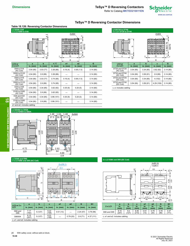
18-48 © 2021 Schneider Electric All Rights Reserved
July 30, 2021
Dimensions TeSys™ D Reversing Contactors
www.se.com/us
Refer to CatalogMKTED210011EN
TeSys™ D Reversing Contactor DimensionsTable 18.126: Reversing Contactor DimensionsLC2D09–D382 x LC1D09 to D38
LC2DT20 to DT402 x LC1 DT20 to DT40
2xM4
G
a
= =
60/70
==c
be1
e2
2.36/2.76
2xM4
G
a
= =
60/70
==c
be2
2.36/2.76
LC2 or2 x LC1
a b c [4] e1 e2 G LC2 or2 x LC1
a b c Gin. (mm) in. (mm) in. (mm) in. (mm) in. (mm) in. (mm) in. (mm) in. (mm) in. (mm) in. (mm)
D09 to D18(AC Coil) 3.54 (90) 3.03 (77) 3.38 (86) 0.16 (4) 0.06 (1.5) 3.14 (80) DT20 and DT25
(AC Coil) 3.54 (90) 3.34 (85) 3.62 (92) 3.14 (80)
D093 to D123(AC Coil) 3.54 (90) 3.9 (99) 3.38 (86) — — 3.14 (80) DT32 and DT40
(AC Coil) 3.54 (90) 3.58 (91) 3.9 (99) 3.14 (80)
D09 to D18(DC Coil) 3.54 (90) 3.03 (77) 3.74 (95) 0.16 (4) 0.06 (1.5) 3.14 (80) DT20 and DT25
(DC Coil) 3.54 (90) 3.34 (85) 4 (102) 3.14 (80)
D093 to D123(DC Coil) 3.54 (90) 3.9 (99) 3.74 (95) — — 3.14 (80) DT32 and DT40
(DC Coil) 3.54 (90) 3.58 (91) 4.29 (109) 3.14 (80)
D25 to D38(AC Coil) 3.54 (90) 3.34 (85) 3.62 (92) 0.35 (9) 0.20 (5) 3.14 (80) c, e: includes cabling
D183 to D383(AC Coil) 3.54 (90) 3.9 (99) 3.62 (92) — — 3.14 (80)
D25 and D32(DC Coil) 3.54 (90) 3.34 (85) 3.98 (101) 0.35 (9) 0.20 (5) 3.14 (80)
D183 to D383(DC Coil) 3.54 (90) 3.9 (99) 3.98 (101) — — 3.14 (80)
e1 and e2: includes cabling
LC2D40A to D65A2 x LC1D40A to D65A
122
128
120
119
6418.7 18.7
6xM4
4.72
4.80
1.48 1.04 1.4826.537.5 37.5
5.04
0.74 0.742.52
4.69
LC2D80 and D952 x LC1D80 and D95 (AC Coil) 2 x LC1D80 and D95 (DC Coil)
c
be1
e2
G1= =
6xØ6.5
1.57
a
= =G 1.57
100
6xØ0.26
8.31
13.5140 40
3.94
110
4.33
LC2 or 2 xLC1
a b c e1 e2 G G12 x LC1
a b c e1 e2 G G1in. (mm) in. (mm) in. (mm) in. (mm) in. (mm) in. (mm) in. (mm) in.
(mm)in.
(mm)in.
(mm)in.
(mm)in.
(mm)in.
(mm)in.
(mm)D80 andD95
7.17(182) 5 (127) 6.22
(158) 0.51 (13) — 2.24 (57) 3.78 (96) D80 and D95 8.15(207)
5.0(127)
8.46(215)
0.51(13)
0.79(20)
3.78(96)
4.37(111)
D80004 8.15(207) 5 (127) 6.22
(158) — 0.79 (20) 2.8 (71) 4.37 (111) c, e1 and e2: includes cabling.
c, e1, and e2: includes cabling
18CONTA
CTORSANDSTA
RTERS-IE
C
[4] With safety cover, without add-on block.
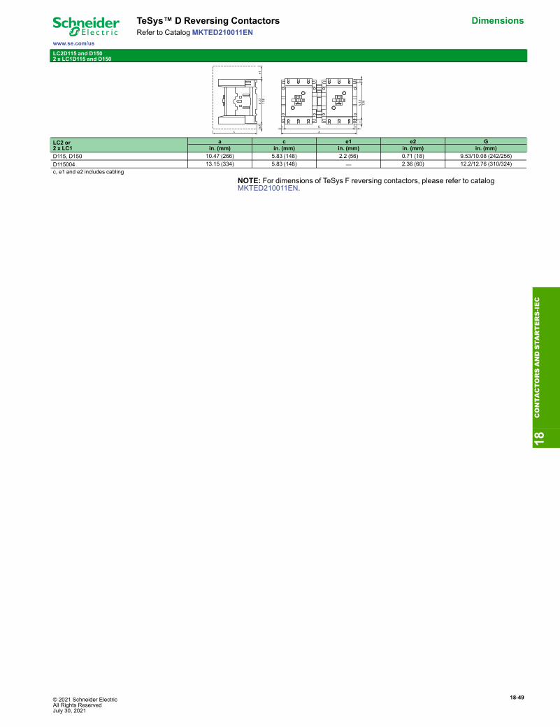
© 2021 Schneider Electric All Rights ReservedJuly 30, 2021
18-49
www.se.com/us
TeSys™ D Reversing Contactors DimensionsRefer to Catalog MKTED210011EN
LC2D115 and D1502 x LC1D115 and D150
LC2 or2 x LC1
a c e1 e2 Gin. (mm) in. (mm) in. (mm) in. (mm) in. (mm)
D115, D150 10.47 (266) 5.83 (148) 2.2 (56) 0.71 (18) 9.53/10.08 (242/256)D115004 13.15 (334) 5.83 (148) — 2.36 (60) 12.2/12.76 (310/324)c, e1 and e2 includes cabling
NOTE: For dimensions of TeSys F reversing contactors, please refer to catalogMKTED210011EN.
6.22
158
e1e2
cGa
= =
5.12
130
==
18CONTA
CTORSANDSTA
RTERS-IEC

18-50 © 2021 Schneider Electric All Rights Reserved
July 30, 2021
Dimensions TeSys™ D Open Starters
www.se.com/us
Refer to CatalogMKTED210011EN
TeSys™ D Open Starter DimensionsTable 18.127: TeSys D Thermal Overload Relay Dimensions, in. (mm)LRD01-35Direct mounting beneath contactors with screw clamp connections
LRD04L-32LDirect mounting beneath contactors with screw clamp connections
b
4576.1
c
DB415912.eps
3 1.77
LC1● D09–D18 D25–D38 LC1● D09–D18 D25–D38b 4.84 (123) 5.39 (137) b 4.84 (123) 5.39 (137)c See page 18-42 c See page 18-42
LR9D01, 02, 08, and 32LRD313–365Direct mounting beneath LC1D40A to D65A with screw clampconnectionsor EverLink connectors
b
80
c
453.151.77
185
7011
5
126
123 554.84
4.96
2.16
2.75
4.53
7.28
LC1● D09–D18 D25–D38b 5.12 (130) 5.51 (140)
c See page 18-42
See page 18-42
LRD33●●●Direct mounting beneath contactorsLC1D80 to D95
AM1● DL201 DL200d 0.28 (7) 0.67 (17)
b c e g (3P) g (4P)AC Control Circuit
LC1D80 4.55 (115.5) 4.88 (124) 3.03 (76.9) 0.37 (9.5) 0.87 (22)LC1D95 4.55 (115.5) 4.88 (124) 3.03 (76.9) 0.37 (9.5) —
DC Control CircuitLP1D80 4.55 (115.5) 7.06 (179.4) 3.03 (76.9) 0.37 (9.5) 0.87 (22)
18CONTA
CTORSANDSTA
RTERS-IE
C

© 2021 Schneider Electric All Rights ReservedJuly 30, 2021
18-51
www.se.com/us
TeSys™ D Open Starters DimensionsRefer to Catalog MKTED210011EN
LRD4●●●[5]Direct mounting beneath contactors LC1D115 and D150
LR9D5●●● and LR9D6●[5]Direct mounting beneath contactors LC1D115 and D150
132 120d
174
255
136
5.20
6.85
10.0
4
5.35
4.72
AM1 DL200 and DR200 DE200 and ED●●● AM1 DP200 and DR200 DE200 and ED●●●d 0.10 (2.5) 0.41 (10.5) d 0.10 (2.5) 0.41 (10.5)
18CONTA
CTORSANDSTA
RTERS-IEC
[5] For additional specifications and selection information, see catalogMKTED210011EN

18-52 © 2021 Schneider Electric All Rights Reserved
July 30, 2021
Dimensions TeSys™ D Overload Relays
www.se.com/us
Refer to CatalogMKTED210011EN
TeSys™ D Thermal Overload Relay DimensionsLRD01–35Independent mounting on 1.97 in. (50 mm) centers or on rail AM1DP200 or DE200 Independent mounting on 4.33 in. (110 mm) centers
LAD 7B106
45280
37.5
85
505
35 10
6
15
DF
5335
89.e
ps
LAD 7B106
110
==
46 = =
2xØ6.5DX1 AP2590
125
DF
5335
90.e
ps
3.15
1.48
3.35
0.08 1.77
0.24
0.20
1.97
.59
1.38 0.39
3.54
4.92
4.33
1.81
LRD04L–32LIndependent mounting on 1.97 in. (50 mm) centers or on rail AM1DP200 or DE200 Independent mounting on 4.33 in. (110 mm) centers
LAD 7B205
45286.1
37.5
85
505
35 10
6
15DB
4158
78R
.eps
LAD 7B205
110
==
46 = =
2xØ6.5DX1 AP25
125
DB
4158
79.e
ps
3.39
1.48
0.08
3.35
1.77 0.24
1.38 0.39.5
91.
970.
24 4.92
4.33
1.81
AM1 DP200 DE200d 0.08 (2) 0.37 (9.5)
LRD313–365Mounting on rail AM1D●200 or ED200 Panel mounting Mounted on plate AM1P
With terminal block LAD96560 Outgoing terminal block not shown
4374
AF1 EA4LAD 96560
2.91
1.69
87
116d
55
LAD 96560 (1)
43
722
2
(1) 2 elongated holes Ø 4.2 x 6.
4.57 2.16
3.42
1.69
0.08
2.8
30.
08
AM1 DP200 DE200 ED200d 0.08 (2) 0.37 (9.5) 0.37 (9.5)
LRD01–35 and LRD313–365Remote tripping or electrical reset
LAD 703 (1)
32
DF
5367
69.e
ps
1.26
(1) Can only be mounted on RH side of relay
18CONTA
CTORSANDSTA
RTERS-IE
C

© 2021 Schneider Electric All Rights ReservedJuly 30, 2021
18-53
www.se.com/us
TeSys™ D Overload Relays DimensionsRefer to Catalog MKTED210011EN
LR9D01–D32 LR9D110S
286.137
.5
85
LAD 7B205
45
505
35 10
6
15
3.39 0.081.
48
3.35
1.77 0.24
1.38 0.39
0.20
1.97
.59
114
120
51.5
d
65
75/87
50
2xØ4.5
= =
4.49
2.03
4.72
2.56
1.97
2.95/3.42
LRD3●●● and LR2D35●●Independent mounting on 1.97 in. (50 mm) centers or on rail AM1DP200 or DE200
LRD3●●●, LR2D35●●, and LR9D5Remote tripping or electrical reset
121
100
2xØ4.5
LA7 D3064
51.5
d
75/8
72
50
75 ==
23.5
32
DF
5335
94.e
ps
119 21
LA7 D03 (1)
DF
5335
95.e
ps
4.76
2.03
3.94 0.08
2.95
1.97
2.95
/3.4
2
0.92
1.26
4.68 0.83
AM1 DP200 DE200 (1) Can be mounted on RH or LH side of relay LRD3●●●, LR2D35●●, or LR9Dd 0.08 (2) 0.37 (9.5)
LRD3●●●Adapter for door-mounted operator
LA7 D1020 Stop Reset
c10
LA7 D1020
DF533596.eps
DF564938.eps
DF564939.eps0.39
c: adjustable from 0.67 to 4.72 (17 to 120)
LRD, LRD313–365, LRD04–32L, LR9D5, and LR9D6“Reset” by flexible cable
LA7D305 and LAD7305Mounting with cable straight
Mounting with cable bent
ce
DF533597.eps
M10x1e
DF533598.eps
e: up to 1.18 (20) e: up to 1.18 (20)c: up to 21.65 (550)
18CONTA
CTORSANDSTA
RTERS-IEC

18-54 © 2021 Schneider Electric All Rights Reserved
July 30, 2021
Dimensions TeSys™ F Overload Relays
www.se.com/us
Refer to CatalogMKTED210011EN
TeSys™ F Overload Relay DimensionsAll dimensions shown in mm.To convert to inches, divide by 25.4.
Table 18.128: TeSys F Overload Relay DimensionsLR9F5●71, F71 LR9F5●57, F5●63, F5●67, F5●69, F57, F63, F67, F69Common side view
4.72120
2.36 60
1.9750
1.9750
2.80 71
Ø11
4xØ5.5
2.2457
1.8547
1.77 45
1.8948
1.8948
.9825
4.53115
.22 6
.113
.113
3.98
101
2.99 76
4.88124
(1)
1) Terminal shroud LA9F70•
2.99 76
1.5740
1.5740
3.78 96
1.9750
1.9750
2.36 60
2.80 71
.22 6
4xØ5.5
4.53115
.7920
(2)
2) 6.5 x 13.5 for LR9F5•57 and F57.8.5 x 13.5 for LR9F5•63, F5•67,F5•69, F63, F67, F69.
LR9F7●75, F7●79, F7●81, F75, F79, F81 LR9F7●81, F81Common side view (for mounting beneath LC1F630 and LC1F800)
4.29
109
.55
14
1.1830
P2 P1
5.94151
Ø11
2.0552
2.0552
2.6066
2.6066
4xØ5.5
2.76 70
.87
22
.24 6
3.23 82
5.39
137
.9825
1.6542
5.04128
.246
1.77 45
(1)
(1) Terminal shroud LA9-F70•
7.44
189
.79
20
7.87200
3.1580
3.1580
7.60193
9.02
229
3.0377
3.0377
2.44 62
Ø13
1.5740
1.5740
P1 P2LR9F7●75, F75 48 48
LR9F7●79, F7●81, F79, F81 55 55
Direct mounting beneath contactor LC1F Direct mounting beneath reversing contactors or star-delta contactors
H2
b
H3
H1
(2)
(2) Relay mounting plate, see .
H2
b
H4
H3
LA7F40•Busbar (1)
(2)
(1) Connection accessories, see .(2) Relay mounting plate, see .
LC1 contactors With LR9 relays b H1 H2 H3 LC1 contactors With LR9 relays b H4 H2 H3
F115 F5●57, F5●63, F5●67, F5●69, F57,F63, F67, F69 240 30 76 120 F115 F5●57, F5●63, F5●67, F5●69,
F57, F63, F67, F69 279 60 76 120
F150 F5●57, F5●63, F5●67, F5●69, F57,F63, F67, F69 246 30 76 120 F150 F5●57, F5●63, F5●67, F5●69,
F57, F63, F67, F69 283 60 76 120
F185 F5●57, F5●63, F5●67, F5●69, F57,F63, F67, F69 250 30 76 120 F185 F5●57, F5●63, F5●67, F5●69,
F57, F63, F67, F69 285 60 76 120
F225F5●71, F71 273 40 76 120
F225F5●71, F71 319 80 76 120
F7●75, F7●79, F75, F79 308 50 108.8 120 F7●75, F7●79, F75, F79 360 100 108.8 120
F265F5●71, F71 279 40 76 120
F265F5●71, F71 332 90 76 120
F7●75, F7●79, F75, F79 314 60 108.8 120 F7●75, F7●79, F75, F79 363 100 108.8 120F330 F7●75, F7●79, F75, F79 317 60 108.8 120 F330 F7●75, F7●79, F75, F79 364 100 108.8 120
F400 F7●75, F7●79, F7●81, F75, F79,F81 317 60 108.8 180 F400 F7●75, F7●79, F7●81, F75, F79,
F81 364 100 108.8 180
F500 F7●75, F7●79, F7●81, F75, F79,F81 346 70 108.8 180 F500 F7●75, F7●79, F7●81, F75, F79,
F81 390 110 108.8 180
F630, F800 F7●81, F81 510 110 108.8 180 F630, F800 F7●81, F81 509 120 108.8 180
18CONTA
CTORSANDSTA
RTERS-IE
C

© 2021 Schneider Electric All Rights ReservedJuly 30, 2021
18-55
www.se.com/us
TeSys™ D Enclosed Starters andCombination Starters
Dimensions
Refer to Catalog MKTED210011EN
TeSys™ D Combination Starter DimensionsTable 18.129: Non-Combination Starter Dimensions [6]Non-Combination Starters
R
.56
14
DD/2
Provision for 1/4" ScrewC
.75
19
F G H
B E
A .50
13J
K
Type 1 Type 12/3RNon-Reversing Reversing A B C D E F G H J K D E
D09-32 — 6.77 10.04 6.25 5.38 9.00 1–1.25 0.5–0.75 — 1–0.25 0.5–0.75 5.38 11.37D40-65 D09-32 8.66 10.83 7.21 7.25 9.75 1.25–1.5 0.5–0.75 1–1.25 1–0.25 0.5–0.75 5.38 12.15
18CONTA
CTORSANDSTA
RTERS-IEC
[6] All dimensions in inches.

18-56 © 2021 Schneider Electric All Rights Reserved
July 30, 2021
Dimensions TeSys™ K Contactors, Overload Relaysand Starters
www.se.com/usRefer to CatalogMKTED210011EN
TeSys™ K Contactor DimensionsTable 18.130: TeSys K Contactor DimensionsLR2KDirect mounting under the contactor
Separate mounting with LA7-K0064 terminal block on 35 mm rail(AM1DP200 or AM1DE200)
.318
2.5665
1.7745
4.57
116
2.28 58
1.97 50
4 x Ø41.3835
2.9575
3.09 (DP200) 783.38 (DE200) 86
1.50 38
3.15 80
1.7745
Three-phase Wiring Scheme
1 3 5
2 4 6
95 97
96 98
AH
Test
Reset/Stop
Internal Links
1 3 5 13 A1
2 4 6 14 A2
2 4 6
97 95 98 96
– KM1
A2
A1
9695
1314
– KM1
O
95
96
LC1, LP1, LP4KMini-contactorsOn baseplate
LC2, LC8, LP2, LP5KReversing mini-contactorsOn baseplate
LA1-K
2.2457
1.2231
2.28 58
4 x Ø4
1.3835
1.97 50
1.7745
On AM1DP200 or DE200 rail (35 mm) On AM1DP200 or DE200 rail (35 mm)
2.2457
2.28 58
1.7745
On printed circuit board On printed circuit board for reversing contactors or 2 mini-contactors side-by-side.349
.349A1
A1
A2
A22.28 58 1.97 50 2.05 52
1.7745
1.7745
20 x Ø.05120 x Ø1.3
LA2KTElectronic time delay contact blocks On mini-contactors or reversing mini-contactors
1.3434
1.5038
1.06 27
2.2457
1.3434
2.28 58
LA2-KT
8 x Ø4
3.1580
3.5490
1.97 50
LA1-K
1.2231
2.28 58
2.2457
2.2457
2.28 58
3.5490
.349
A1
A2
2.28 58 1.97 50 2.05 52
1.7745
10 x Ø.05110 x Ø1.3
18CONTA
CTORSANDSTA
RTERS-IE
C

© 2021 Schneider Electric All Rights ReservedJuly 30, 2021
18-57
www.se.com/us
TeSys™ U Open Motor Starters DimensionsRefer to Catalog 8502CT0201
TeSys™ U Starter DimensionsTable 18.131: TeSys U Starter DimensionsStarter Controllers
Non-Reversing [7] ReversingRail Mounting Screw Mounting Rail Mounting Screw Mounting
1264.96
135 5.31
154
6.06
X1
X1 451.77
X2
X2
1264.96
135 5.31
73 2.87
301.18
Ø4 .15
163
6.42
224
8.82
451.77
120/
125
4.72
/4.9
2
233
9.17
291.14
Ø4.15
NOTE: Minimum electrical clearance:X1: 35 mm for Ue = 440 V; and 70 mm for Ue = 500 and 690 VX2: 0
Reversing Block for Mounting Separately from Power BaseRail Mounting Screw Mounting
451.77
1134.45
115
4.53
1134.45 36
1.41
104
4.09
Ø4 .15
Limiter Disconnector LUALB1 [7]
451.77
93 3.66
154
6.06
135 5.31
Door interlock MechanismsLU9APN43 and LU9APN44
2.36
59.9
7.05 to 18.72 179 to 475.5
1.73 43.9
9.3
423
7.2
2.50
63.5
8.6
622
0.0
0.29
7.3
0.97
24.6
0.77 (19.6)
1.3133.3
1.1830.0
3.87 (98.2)
provision for 1/4 screws (2x)
18CONTA
CTORSANDSTA
RTERS-IEC
[7] Maximum depth (with Modbus™ communication module)

18-58 © 2021 Schneider Electric All Rights Reserved
July 30, 2021
Dimensions Soft Starter Module ATSU01
www.se.com/us
Refer to CatalogMKTED210011EN
Altistart U01 and TeSys U Soft Starters, MountingTable 18.132: Altistart U01 and TeSys U Soft Starters
TeSys U Combination (non-reversing power base) and ATSU01N212LT TeSys U Combination (non-reversing power base) andATSU01N222LT to ATSU01N232LT
Mounting on (35 mm) rail with VW3 G4104 connector Mounting on (35 mm) rail with VW3G4104 connector
150
5.91
284
11.1
8
451.77
90.354
314
12.36
451.77
170
6.69
90.354
TeSys U Combination (non-reversing or reversing power base) andATSU01N2206LT to ATSU01N212LT
TeSys U Combination (non-reversing or reversing power base) andATSU01N222LT to ATSU01N232LT
Side-by-side mounting Side-by-side mounting
993.9
1355.31
154
6.06
72.2
2.84
9
124
4.88
0.354
993.9
1355.31
72.2
2.84
154
6.06
90.354
VW3G4104 Power Connector
44.81.76
200.79
6 0.24
46.6
1.83
28 1.10
18CONTA
CTORSANDSTA
RTERS-IE
C

© 2021 Schneider Electric All Rights ReservedJuly 30, 2021
18-59
www.se.com/us
TeSys™ GV Manual Starters and Protectors DimensionsRefer to Catalog 2520CT0001
TeSys GV2 and GV3 Manual Starter and Protector DimensionsTable 18.133: TeSys GV2 and GV3 Manual Starter and Protector Dimensions
GV2M GV2AD, AM, AN, AU, AS, AX GV2AE Mounting of GV2M
89
66
4416
11.43
.63 1.73
2.60
3.5
45=
=44.51.75
1.77
9.3 9.3
81
18.37 .37 .71
3.19
Block GV2AD, AM, ANBlock GV2AU, AS, AX 15
.59
10 .39
c
44.5
44.5
1.75
1.75
On 35 mm railC = 78.5 mm (3.09") on AM1DP200 (35 x 7.5 mm)C = 86 mm (3.39") on AM1DE200, ED200 (35 x 15 mm)
GV2P GV2AD, AM, AN, AU, AS, AX GV2AK00 Mounting of GV2P
89
82
50261.02 1.97
3.23
3.50
44.5
6145
==
1.75
1.77
2.40
.5915
9.3 9.3
81
1818.37 .37
3.19
.71
Block GV2AD, AM, ANBlock GV2AU, AS, AX 9814
.55 3.86
44.5
32 1.26
1.75
44.5
c
44.5
1.75
1.75
13.5
84
.53
3.31
On 35 mm railC = 98.5 mm (3.88") on AM1DP200(35 x 7.5 mm)C = 106 mm (4.17") on AM1DE200, ED200(35 x 15 mm)
GV2AF4 + LAD31 GV2P + GV2GH7 GV2P + GV2GH7 + TeSys D contactorCombination GV2ME + TeSys D range
contactorCombination GV2P + TeSys D range
contactor for UL 508 Type E application for UL 508 Type E application
c1
c
d1
d
451.77
b
451.77
b
c1
c10
34.
0744
1.73
191
7.50
3.6 (91.4)3.6 (91.4)
3.8 (96.52)3.8 (96.52)
GV2ME + LC2D09 to D18 LC2D25 and D32 GV2P + LC2D09 to D18 LC2D25 and D32b 7.4 (188.6) 7.8 (199) b 6.61 (168.1) 7.9 (199.5)c1 3.6 (92.7) 3.9 (99) c1 4.6 (116.8) 4.6 (116.8)c 3.9 (98.2) 4.11 (104.5) c 4.8 (122.3) 4.8 (122.3)d1 3.9 (98.3) 3.9 (98.3) — — —d 4.1 (103.8) 1.4 (103.8) — — —
Surface mounting enclosure GV2MC0● Flush mounting enclosure GV2MP0● (bracket cut-out)4 knock-outs for 16 mm plastic cable glands or no. 16 conduit.
147
843.31
5.79
933.66
2xØ5.3x6.3
=
130
==
=
5.12
1...6
84130.51 3.31
/0.04...0.24
b
=b1
= = 93.5 =
106.53.68
4.19
71
92.8
6.52.8
3.65
0.25
GV2 b b1in. mm in. mm
MP01, MP02 5.51 140 5.00 127MP03, MP04 5.24 133 4.61 117
18CONTA
CTORSANDSTA
RTERS-IEC

18-60 © 2021 Schneider Electric All Rights Reserved
July 30, 2021
Dimensions TeSys™ GV Manual Starters and Protectors
www.se.com/us
Refer to Catalog 2520CT0001
Table 18.134: TeSys GV2 and GV3 Manual Starter and Protector Dimensions (cont’d)GV2M with GK2AF01 and LC1K GV2M with GV2AF01 and LC1K GV2M with GV2AF01 and LC2K Adapter Plate GK2AF01
Dimensions (mm)
793.11
45
152
1.77
6.0
152
903.54
6.0
24
5545
135
9.5.94 .37
1.77
2.17
5.31 45
35
54
105
±5
35
Ø5.5
51.38
1.38
1.77
2.13
4.13
±.2
.2
.22
Mounting external operatorGV2AP0● Door cut-out GV2M on panel
with GV2AF02 adapter plate7.5 mm height compensation plate
GV1F03
min.=150
7
53
65
5.2
= =
1.5...5max.=290
2.56
2.1 5.91
/0.06...0.20
11.42 0.21
.276
54= =
==
54
4xØ3.5 0.14
Ø43 1.7
2.13
2.13
803.15
50/6
0
4.2
351.38
1.97
/2.3
6
.17
130.51
351.38
39 1.54
Sets of bus bars, GV2G445, GV2G454, GV2G472 with terminal block GV2G05 Sets of bus bars with terminal block GV1G09 Sets of bus bars GV2G245,GV2G254, GV2G272
632.5
l3.12
18.71 p
451.8
301.2
l
I P IGV2G445 0.16 x 1.8 in. (4 x 45 mm) 7.0 in. (179 mm) 1.8 in. (45 mm) GV2G245 0.08 x 1.8 in. (2 x 45 mm) 3.5 in. (89 mm)GV2G454 0.16 x 2.1 in. (4 x 54 mm) 8.1 in. (206 mm) 2.1 in. (54 mm) GV2G254 0.08 x 2.1 in. (2 x 54 mm) 3.9 in. (98 mm)GV2G472 0.16 x 1.8 in. (4 x 45 mm) 10.2 in. (260 mm) 2.8 in. (72 mm) GV2G272 0.08 x 2.8 in.(2 x 72 mm) 4.6 in. (116 mm)
GV2G354 0.12 x 2.1 in. (3 x 54 mm) 6.0 in. (152 mm)
GV3PDimension Mounting on rail AM1 DE200 or AM1 ED201
136
X1
X1
132
6864
55
X1 = Electrical clearance (ISC max)40 mm for Ue < 500 V; 50 mm for Ue < 690 V
9 18
(2)(1)
Blocks GVAN●●, GVAD●●, GVAM11Block GV3 AU●● and GV3 AS●●
144
6864
Mounting on panel, using M4 screws Mounting on pre-slotted mounting plate AM1PA
136
3xØ4 137,
5
37,5 136 18,7 18,7
137,
5
AF1 EA4
183
16
NOTE: Leave a space of 9 mm between 2 manual motor protectors: either an empty space or side-mounting add-on contact blocks.Horizontal mounting is possible: please consult your regional sales office.
18CONTA
CTORSANDSTA
RTERS-IE
C
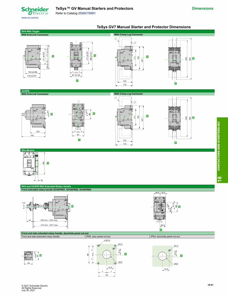
© 2021 Schneider Electric All Rights ReservedJuly 30, 2021
18-61
www.se.com/us
TeSys™ GV Manual Starters and Protectors DimensionsRefer to Catalog 2520CT0001
TeSys GV7 Manual Starter and Protector DimensionsBV4 With ToggleWith EverLink Connector With Crimp Lug Connector
GV4PBWith EverLink Connector With Crimp Lug Connector
SDx Module
BV4 and GV4PBWith Extended Rotary HandleFront extended rotary handle GV4APN01, GV4APN02, GV4APN04
Front and side extended rotary handle, door/side panel cut-outFront and side extended rotary handle IP65, door panel cut-out IP54, door/side panel cut-out
X
111
(4.3
7)
156
(6.1
4) (1
) 171
(6.7
4) (2
)
103 (4.06)
116 (4.57)
X
Y
111
(4.3
7)
188
(7.4
1)
= =81 (3.19)
X
103
116
111
159
167
(1)
(2)
X
Y
255
284
103
165
8.5
X X
Y
= =
81
68
8.5
7
X
103
116
111
159
167
(1)
(2)
X
Y
255
284
18
148 X
208 min. / 620 max.
214 min. / 627 max.
X
44
2.5
Trip
O
I
36.5
40.5
32.548.5
7
2.5
6831.5
X
Y
Ø4...8
Trip
Off
On
Reset
2.5
60
60 X
15.9
4 Ø3.5
Ø3.5
Ø22
15.9
= =
48
==
48 X 15.9
Ø3.5
Ø22
15.9
X
18CONTA
CTORSANDSTA
RTERS-IEC

18-62 © 2021 Schneider Electric All Rights Reserved
July 30, 2021
Dimensions TeSys™ GV Manual Starters and Protectors
www.se.com/us
Refer to Catalog 2520CT0001
Table 18.135: GV5PB and GV6PB Motor Protective Circuit BreakersCircuit Breaker Frame Dimensions— Inches
A B C D E F GGV5PB150 6.40 4.12 2.87 4.36 0.74 1.92 1.38GV5PB250 7.52 4.12 2.87 5.00 1.30 4.92 1.38GV6PB 13.38 5.51 3.75 6.61 2.22 7.87 1.77
GV5PB GV6PB
C
DA
E
F
BG
A
C
D
B
G
F
18CONTA
CTORSANDSTA
RTERS-IE
C