Solid State Relays 1-Phase with Integrated Heatsink Zero ...
30
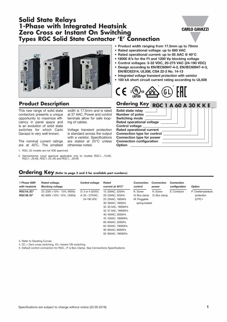
Specifications are subject to change without notice (22.05.2018) 1 • Product width ranging from 17.5mm up to 70mm • Rated operational voltage: up to 660 VAC • Rated operational current: up to 85 AAC @ 40°C • 18000 A 2 s for the I 2 t and 1200 Vp blocking voltage • Control voltages: 3-32 VDC, 20-275 VAC (24-190 VDC) • Design according to EN/IEC60947-4-2, EN/IEC60947-4-3, EN/IEC62314, UL508, CSA 22-2 No. 14-13 • Integrated voltage transient protection with varistor • 100 kA short circuit current rating according to UL508 Solid State Relays 1-Phase with Integrated Heatsink Zero Cross or Instant On Switching Types RGC Solid State Contactor ‘E’ Connection Solid state relay Number of poles Switching mode Rated operational voltage Control voltage Rated operational current Connection type for control Connection type for power Connection configuration Option Product Description Ordering Key RGC 1 A 60 A 30 K K E _ Ordering Key (Refer to page 2 and 3 for available part numbers) 1 Phase SSR Rated voltage, Control voltage Rated Connection Connection Connection with heatsink Blocking voltage current at 40˚C 3 control power configuration Option RGC1A: ZC 4 23: 230V +10% - 15%, 800Vp D: 3 or 4-32VDC 15: 20AAC, 525A²s K: Screw K: Screw E: Contactor P: Overtemperature RGC1B: IO 4 60: 600V +10% -15%, 1200Vp A: 20 - 275VAC, 20: 23AAC, 525A²s G: Box clamp G: Box clamp protection 24-190 VDC 25: 25AAC, 1800A²s M: Pluggable (OTP) 5 30: 30AAC, 1800A²s spring-loaded 32: 30 AAC, 18000A 2 s 32: 37 AAC, 18000A 2 s 40: 40AAC, 3200A²s 42: 43AAC, 18000A²s 60: 60AAC, 3200A²s 62: 65AAC, 18000A²s 90: 85AAC, 6600A²s 92: 85AAC, 18000A²s 3. Refer to Derating Curves 4. ZC = Zero cross switching, IO= Instant ON switching 5. Default control connection for RGC...P is Box Clamp. See Connections Specifications This new range of solid state contactors presents a unique opportunity to maximize effi- ciency in panel space and is an evolution of solid state switches for which Carlo Gavazzi is very well known. The nominal current ratings are at 40˚C. The smallest width is 17.5mm and is rated at 37 AAC. Power and control teminals allow for safe loop- ing of cables. Voltage transient protection is standard across the output with a varistor. Specifications are stated at 25°C unless otherwise noted. 1. RGC..32 models are not VDE approved 2. Germanischer Lloyd approval applicable only to models RGC1....15.KE, RGC1...20.KE, RGC1..25..KE and RGC1....30.KE 1 2
-
Upload
khangminh22 -
Category
Documents
-
view
4 -
download
0
Transcript of Solid State Relays 1-Phase with Integrated Heatsink Zero ...
Specifications are subject to change without notice (22.05.2018) 1
• Product width ranging from 17.5mm up to 70mm• Rated operational voltage: up to 660 VAC• Rated operational current: up to 85 AAC @ 40°C• 18000 A2s for the I2t and 1200 Vp blocking voltage• Control voltages: 3-32 VDC, 20-275 VAC (24-190 VDC)• Design according to EN/IEC60947-4-2, EN/IEC60947-4-3,
EN/IEC62314, UL508, CSA 22-2 No. 14-13• Integrated voltage transient protection with varistor • 100 kA short circuit current rating according to UL508
Solid State Relays1-Phase with Integrated HeatsinkZero Cross or Instant On Switching Types RGC Solid State Contactor ‘E’ Connection
Solid state relay Number of poles Switching mode Rated operational voltage Control voltage Rated operational current Connection type for control Connection type for power Connection configuration Option
Product Description Ordering Key RGC 1 A 60 A 30 K K E _
Ordering Key (Refer to page 2 and 3 for available part numbers)
1 Phase SSR Rated voltage, Control voltage Rated Connection Connection Connection with heatsink Blocking voltage current at 40˚C3 control power configuration Option
RGC1A: ZC4 23: 230V +10% - 15%, 800Vp D: 3 or 4-32VDC 15: 20AAC, 525A²s K: Screw K: Screw E: Contactor P: OvertemperatureRGC1B: IO4 60: 600V +10% -15%, 1200Vp A: 20 - 275VAC, 20: 23AAC, 525A²s G: Box clamp G: Box clamp protection 24-190 VDC 25: 25AAC, 1800A²s M: Pluggable (OTP) 5 30: 30AAC, 1800A²s spring-loaded 32: 30 AAC, 18000A2s 32: 37 AAC, 18000A2s 40: 40AAC, 3200A²s 42: 43AAC, 18000A²s 60: 60AAC, 3200A²s 62: 65AAC, 18000A²s 90: 85AAC, 6600A²s 92: 85AAC, 18000A²s
3. Refer to Derating Curves4. ZC = Zero cross switching, IO= Instant ON switching5. Default control connection for RGC...P is Box Clamp. See Connections Specifications
This new range of solid state contactors presents a unique opportunity to maximize effi-ciency in panel space and is an evolution of solid state switches for which Carlo Gavazzi is very well known.
The nominal current ratings are at 40˚C. The smallest
width is 17.5mm and is rated at 37 AAC. Power and control teminals allow for safe loop-ing of cables.
Voltage transient protection is standard across the output with a varistor. Specifications are stated at 25°C unless otherwise noted.
1. RGC..32 models are not VDE approved
2. Germanischer Lloyd approval applicable only to models RGC1....15.KE, RGC1...20.KE, RGC1..25..KE and RGC1....30.KE
1 2
2 Specifications are subject to change without notice (22.05.2018)
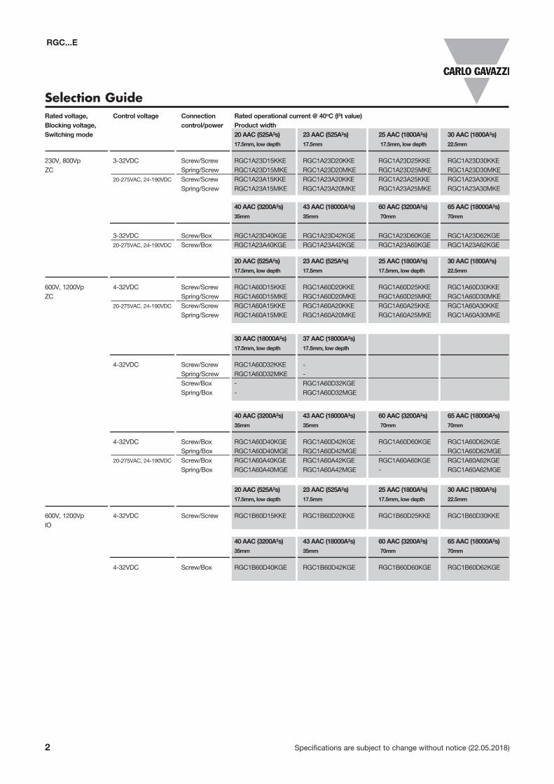
Selection Guide
40 AAC (3200A²s) 43 AAC (18000A²s) 60 AAC (3200A²s) 65 AAC (18000A²s) 35mm 35mm 70mm 70mm
4-32VDC Screw/Box RGC1A60D40KGE RGC1A60D42KGE RGC1A60D60KGE RGC1A60D62KGE Spring/Box RGC1A60D40MGE RGC1A60D42MGE - RGC1A60D62MGE 20-275VAC, 24-190VDC Screw/Box RGC1A60A40KGE RGC1A60A42KGE RGC1A60A60KGE RGC1A60A62KGE Spring/Box RGC1A60A40MGE RGC1A60A42MGE - RGC1A60A62MGE
40 AAC (3200A²s) 43 AAC (18000A²s) 60 AAC (3200A²s) 65 AAC (18000A²s) 35mm 35mm 70mm 70mm
4-32VDC Screw/Box RGC1B60D40KGE RGC1B60D42KGE RGC1B60D60KGE RGC1B60D62KGE
20 AAC (525A²s) 23 AAC (525A²s) 25 AAC (1800A²s) 30 AAC (1800A²s) 17.5mm, low depth 17.5mm 17.5mm, low depth 22.5mm
600V, 1200Vp 4-32VDC Screw/Screw RGC1B60D15KKE RGC1B60D20KKE RGC1B60D25KKE RGC1B60D30KKEIO
RGC...E
20 AAC (525A²s) 23 AAC (525A²s) 25 AAC (1800A²s) 30 AAC (1800A²s) 17.5mm, low depth 17.5mm 17.5mm, low depth 22.5mm
600V, 1200Vp 4-32VDC Screw/Screw RGC1A60D15KKE RGC1A60D20KKE RGC1A60D25KKE RGC1A60D30KKEZC Spring/Screw RGC1A60D15MKE RGC1A60D20MKE RGC1A60D25MKE RGC1A60D30MKE 20-275VAC, 24-190VDC Screw/Screw RGC1A60A15KKE RGC1A60A20KKE RGC1A60A25KKE RGC1A60A30KKE Spring/Screw RGC1A60A15MKE RGC1A60A20MKE RGC1A60A25MKE RGC1A60A30MKE
30 AAC (18000A²s) 37 AAC (18000A²s) 17.5mm, low depth 17.5mm, low depth
4-32VDC Screw/Screw RGC1A60D32KKE - Spring/Screw RGC1A60D32MKE - Screw/Box - RGC1A60D32KGE Spring/Box - RGC1A60D32MGE
Rated voltage, Control voltage Connection Rated operational current @ 40oC (I2t value) Blocking voltage, control/power Product widthSwitching mode 20 AAC (525A²s) 23 AAC (525A²s) 25 AAC (1800A²s) 30 AAC (1800A²s) 17.5mm, low depth 17.5mm 17.5mm, low depth 22.5mm
230V, 800Vp 3-32VDC Screw/Screw RGC1A23D15KKE RGC1A23D20KKE RGC1A23D25KKE RGC1A23D30KKE ZC Spring/Screw RGC1A23D15MKE RGC1A23D20MKE RGC1A23D25MKE RGC1A23D30MKE 20-275VAC, 24-190VDC Screw/Screw RGC1A23A15KKE RGC1A23A20KKE RGC1A23A25KKE RGC1A23A30KKE Spring/Screw RGC1A23A15MKE RGC1A23A20MKE RGC1A23A25MKE RGC1A23A30MKE
40 AAC (3200A²s) 43 AAC (18000A²s) 60 AAC (3200A²s) 65 AAC (18000A²s) 35mm 35mm 70mm 70mm
3-32VDC Screw/Box RGC1A23D40KGE RGC1A23D42KGE RGC1A23D60KGE RGC1A23D62KGE 20-275VAC, 24-190VDC Screw/Box RGC1A23A40KGE RGC1A23A42KGE RGC1A23A60KGE RGC1A23A62KGE
Specifications are subject to change without notice (22.05.2018) 3
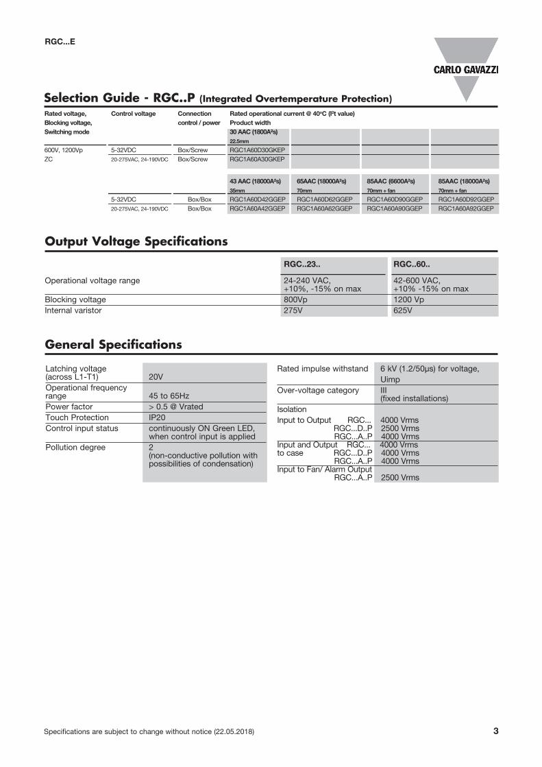
Selection Guide - RGC..P (Integrated Overtemperature Protection)
RGC...E
Output Voltage Specifications
RGC..23.. RGC..60.. Operational voltage range 24-240 VAC, 42-600 VAC, +10%, -15% on max +10% -15% on max Blocking voltage 800Vp 1200 Vp Internal varistor 275V 625V
Latching voltage (across L1-T1) 20VOperational frequency range 45 to 65HzPower factor > 0.5 @ VratedTouch Protection IP20Control input status continuously ON Green LED, when control input is appliedPollution degree 2 (non-conductive pollution with possibilities of condensation)
Rated impulse withstand 6 kV (1.2/50μs) for voltage, Uimp Over-voltage category III (fixed installations)Isolation Input to Output RGC... 4000 Vrms RGC...D..P 2500 Vrms RGC...A..P 4000 VrmsInput and Output RGC... 4000 Vrmsto case RGC...D..P 4000 Vrms RGC...A..P 4000 VrmsInput to Fan/ Alarm Output RGC...A..P 2500 Vrms
General Specifications
43 AAC (18000A²s) 65AAC (18000A²s) 85AAC (6600A²s) 85AAC (18000A²s) 35mm 70mm 70mm + fan 70mm + fan 5-32VDC Box/Box RGC1A60D42GGEP RGC1A60D62GGEP RGC1A60D90GGEP RGC1A60D92GGEP 20-275VAC, 24-190VDC Box/Box RGC1A60A42GGEP RGC1A60A62GGEP RGC1A60A90GGEP RGC1A60A92GGEP
Rated voltage, Control voltage Connection Rated operational current @ 40oC (I2t value) Blocking voltage, control / power Product widthSwitching mode 30 AAC (1800A²s)
22.5mm
600V, 1200Vp 5-32VDC Box/Screw RGC1A60D30GKEPZC 20-275VAC, 24-190VDC Box/Screw RGC1A60A30GKEP
RGC...E
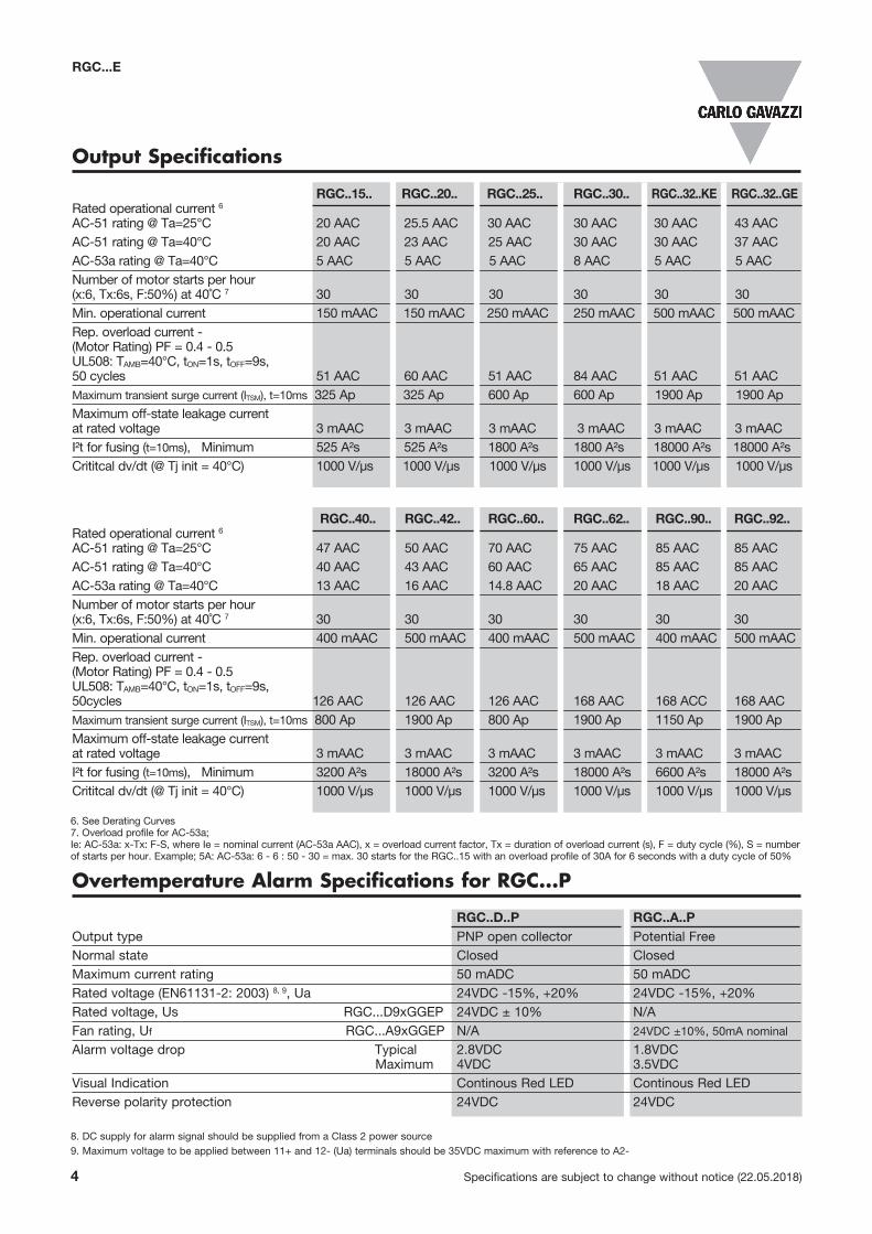
Output Specifications
RGC..15.. RGC..20.. RGC..25.. RGC..30.. RGC..32..KE RGC..32..GE Rated operational current 6 AC-51 rating @ Ta=25°C 20 AAC 25.5 AAC 30 AAC 30 AAC 30 AAC 43 AACAC-51 rating @ Ta=40°C 20 AAC 23 AAC 25 AAC 30 AAC 30 AAC 37 AACAC-53a rating @ Ta=40°C 5 AAC 5 AAC 5 AAC 8 AAC 5 AAC 5 AACNumber of motor starts per hour (x:6, Tx:6s, F:50%) at 40˚C 7 30 30 30 30 30 30Min. operational current 150 mAAC 150 mAAC 250 mAAC 250 mAAC 500 mAAC 500 mAACRep. overload current - (Motor Rating) PF = 0.4 - 0.5 UL508: TAMB=40°C, tON=1s, tOFF=9s, 50 cycles 51 AAC 60 AAC 51 AAC 84 AAC 51 AAC 51 AACMaximum transient surge current (ITSM), t=10ms 325 Ap 325 Ap 600 Ap 600 Ap 1900 Ap 1900 ApMaximum off-state leakage current at rated voltage 3 mAAC 3 mAAC 3 mAAC 3 mAAC 3 mAAC 3 mAACI²t for fusing (t=10ms), Minimum 525 A²s 525 A²s 1800 A²s 1800 A²s 18000 A²s 18000 A²sCrititcal dv/dt (@ Tj init = 40°C) 1000 V/μs 1000 V/μs 1000 V/μs 1000 V/μs 1000 V/μs 1000 V/μs
4 Specifications are subject to change without notice (22.05.2018)
RGC..40.. RGC..42.. RGC..60.. RGC..62.. RGC..90.. RGC..92.. Rated operational current 6 AC-51 rating @ Ta=25°C 47 AAC 50 AAC 70 AAC 75 AAC 85 AAC 85 AACAC-51 rating @ Ta=40°C 40 AAC 43 AAC 60 AAC 65 AAC 85 AAC 85 AACAC-53a rating @ Ta=40°C 13 AAC 16 AAC 14.8 AAC 20 AAC 18 AAC 20 AACNumber of motor starts per hour (x:6, Tx:6s, F:50%) at 40˚C 7 30 30 30 30 30 30Min. operational current 400 mAAC 500 mAAC 400 mAAC 500 mAAC 400 mAAC 500 mAACRep. overload current - (Motor Rating) PF = 0.4 - 0.5 UL508: TAMB=40°C, tON=1s, tOFF=9s, 50cycles 126 AAC 126 AAC 126 AAC 168 AAC 168 ACC 168 AACMaximum transient surge current (ITSM), t=10ms 800 Ap 1900 Ap 800 Ap 1900 Ap 1150 Ap 1900 ApMaximum off-state leakage current at rated voltage 3 mAAC 3 mAAC 3 mAAC 3 mAAC 3 mAAC 3 mAACI²t for fusing (t=10ms), Minimum 3200 A²s 18000 A²s 3200 A²s 18000 A²s 6600 A²s 18000 A²sCrititcal dv/dt (@ Tj init = 40°C) 1000 V/μs 1000 V/μs 1000 V/μs 1000 V/μs 1000 V/μs 1000 V/μs
6. See Derating Curves7. Overload profile for AC-53a;Ie: AC-53a: x-Tx: F-S, where Ie = nominal current (AC-53a AAC), x = overload current factor, Tx = duration of overload current (s), F = duty cycle (%), S = number of starts per hour. Example; 5A: AC-53a: 6 - 6 : 50 - 30 = max. 30 starts for the RGC..15 with an overload profile of 30A for 6 seconds with a duty cycle of 50%
8. DC supply for alarm signal should be supplied from a Class 2 power source9. Maximum voltage to be applied between 11+ and 12- (Ua) terminals should be 35VDC maximum with reference to A2-
Overtemperature Alarm Specifications for RGC...P
RGC..D..P RGC..A..POutput type PNP open collector Potential FreeNormal state Closed ClosedMaximum current rating 50 mADC 50 mADCRated voltage (EN61131-2: 2003) 8, 9, Ua 24VDC -15%, +20% 24VDC -15%, +20%Rated voltage, Us RGC...D9xGGEP 24VDC ± 10% N/AFan rating, Uf RGC...A9xGGEP N/A 24VDC ±10%, 50mA nominal
Alarm voltage drop Typical 2.8VDC 1.8VDC Maximum 4VDC 3.5VDCVisual Indication Continous Red LED Continous Red LEDReverse polarity protection 24VDC 24VDC
Specifications are subject to change without notice (22.05.2018) 5
RGC...E
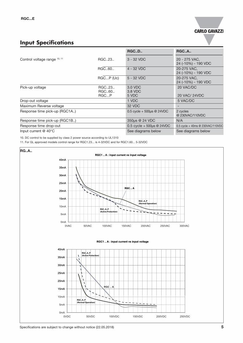
Input Specifications RGC..D.. RGC..A.. Control voltage range 10, 11 RGC..23.. 3 - 32 VDC 20 - 275 VAC, 24 (-10%) - 190 VDC RGC..60.. 4 - 32 VDC 20-275 VAC, 24 (-10%) - 190 VDC RGC...P (Uc) 5 - 32 VDC 20-275 VAC, 24 (-10%) - 190 VDCPick-up voltage RGC..23.. 3.0 VDC 20 VAC/DC RGC..60.. 3.8 VDC RGC...P 5 VDC 20 VAC/ 24VDCDrop-out voltage 1 VDC 5 VAC/DC Maximum Reverse voltage 32 VDC -Response time pick-up (RGC1A..) 0.5 cycle + 500µs @ 24VDC 2 cycles @ 230VAC/110VDC
Response time pick-up (RGC1B..) 350µs @ 24 VDC N/A Response time drop-out 0.5 cycle + 500µs @ 24VDC 0.5 cycle + 40ms @ 230VAC/110VDC
Input current @ 40°C See diagrams below See diagrams below
10. DC control to be supplied by class 2 power source according to UL1310
11. For GL approved models control range for RGC1.23... is 4-32VDC and for RGC1.60... 5-32VDC
RG..A..
15mA
20mA
25mA
30mA
35mA
40mA
RGC1 .. A : input current vs input voltage
RGC .. A
0mA
5mA
10mA
15mA
20mA
25mA
30mA
35mA
40mA
0VAC 50VAC 100VAC 150VAC 200VAC 250VAC 300VAC
RGC1 .. A : input current vs input voltage
RGC .. A
15mA
20mA
25mA
30mA
35mA
40mA
RGC1 .. A : input current vs input voltage
0mA
5mA
10mA
15mA
20mA
25mA
30mA
35mA
40mA
0VDC 50VDC 100VDC 150VDC 200VDC 250VDC
RGC1 .. A : input current vs input voltage
RGC .. A
RGC..A..P(Normal Operation)
RGC..A..P(Normal Operation)
RGC..A..P(Active Protection)
RGC..A..P(Active Protection)
6 Specifications are subject to change without notice (22.05.2018)
10.0mA
15.0mA
20.0mA
25.0mAA1 Characteristics: DC input current vs Input voltage
5.0mA
10.0mA
15.0mA
20.0mA
25.0mA
2V 4V 6V 8V 10V 12V 14V 16V 18V 20V 22V 24V 26V 28V 30V 32V 34V
A1 Characteristics: DC input current vs Input voltage x
x
5.0mA
10.0mA
15.0mA
20.0mAIN1 Characteristics: DC input current vs Input voltage
0.0mA
5.0mA
10.0mA
15.0mA
20.0mA
2V 4V 6V 8V 10V 12V 14V 16V 18V 20V 22V 24V 26V 28V 30V 32V 34V
IN1 Characteristics: DC input current vs Input voltage
RGC..D..P(Normal Operation)
RGC..D..P(Active Protection)
y
RGC..D9xGGEP(Active Protection)
RGC..D9xGGEP(Normal Operation)
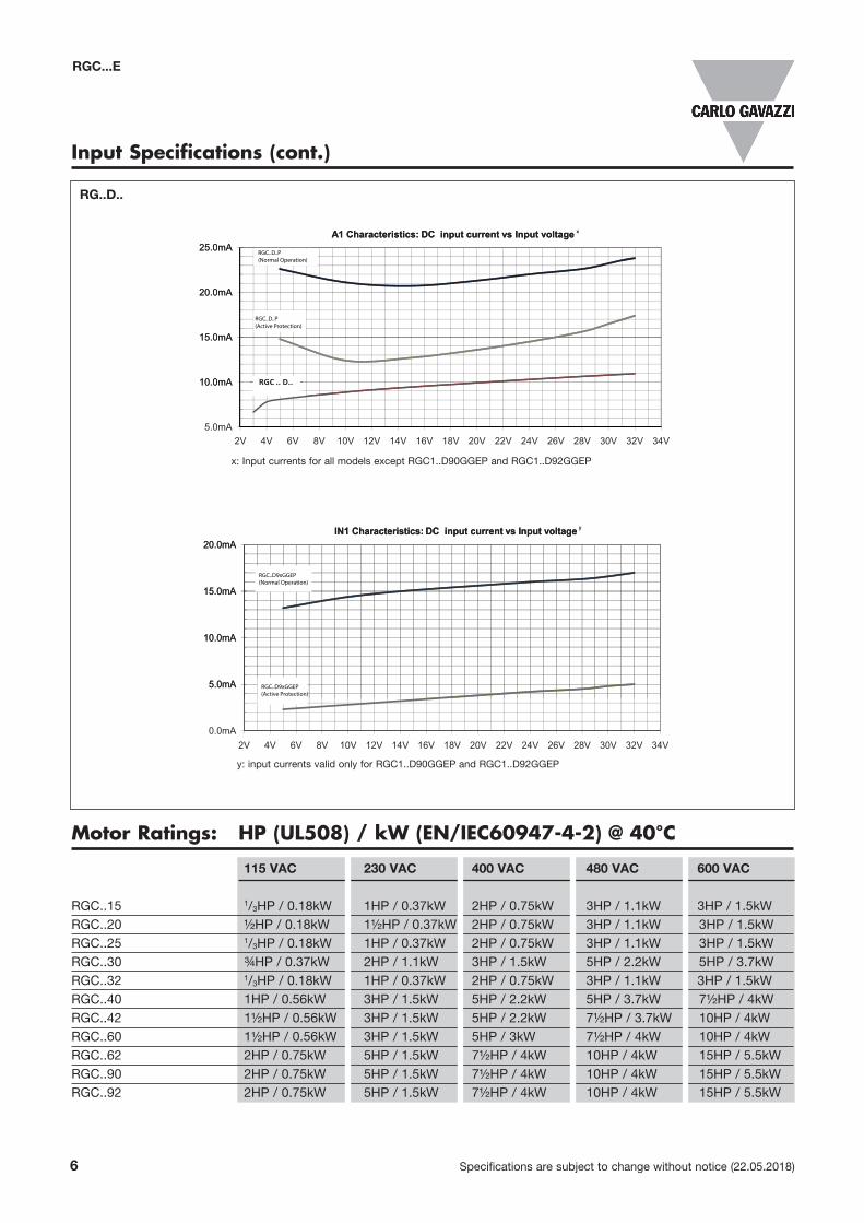
Input Specifications (cont.)
RG..D..
x: Input currents for all models except RGC1..D90GGEP and RGC1..D92GGEP
y: input currents valid only for RGC1..D90GGEP and RGC1..D92GGEP
RGC...E
Motor Ratings: HP (UL508) / kW (EN/IEC60947-4-2) @ 40°C
115 VAC 230 VAC 400 VAC 480 VAC 600 VAC
RGC..15 1/3HP / 0.18kW 1HP / 0.37kW 2HP / 0.75kW 3HP / 1.1kW 3HP / 1.5kWRGC..20 ½HP / 0.18kW 1½HP / 0.37kW 2HP / 0.75kW 3HP / 1.1kW 3HP / 1.5kWRGC..25 1/3HP / 0.18kW 1HP / 0.37kW 2HP / 0.75kW 3HP / 1.1kW 3HP / 1.5kWRGC..30 ¾HP / 0.37kW 2HP / 1.1kW 3HP / 1.5kW 5HP / 2.2kW 5HP / 3.7kWRGC..32 1/3HP / 0.18kW 1HP / 0.37kW 2HP / 0.75kW 3HP / 1.1kW 3HP / 1.5kWRGC..40 1HP / 0.56kW 3HP / 1.5kW 5HP / 2.2kW 5HP / 3.7kW 7½HP / 4kWRGC..42 1½HP / 0.56kW 3HP / 1.5kW 5HP / 2.2kW 7½HP / 3.7kW 10HP / 4kWRGC..60 1½HP / 0.56kW 3HP / 1.5kW 5HP / 3kW 7½HP / 4kW 10HP / 4kWRGC..62 2HP / 0.75kW 5HP / 1.5kW 7½HP / 4kW 10HP / 4kW 15HP / 5.5kWRGC..90 2HP / 0.75kW 5HP / 1.5kW 7½HP / 4kW 10HP / 4kW 15HP / 5.5kWRGC..92 2HP / 0.75kW 5HP / 1.5kW 7½HP / 4kW 10HP / 4kW 15HP / 5.5kW
Specifications are subject to change without notice (22.05.2018) 7
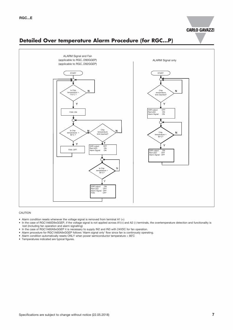
RGC...E
Detailed Over temperature Alarm Procedure (for RGC...P)
ALARM Signal onlyALARM Signal and FAN
START
FAN: ON
Is Chip temperature >
115°C ?
N
Y
Chip temperature <
85°C ?
N
Y
START
N
Y
N
YSSR output: OFFRed LED: ONAlarm Signal: ON
Y
N Chiptemperature <
80°C?
FAN: OFF
Chip temperature
limit reached?
SSR output: ONRed LED: OFFAlarm Signal: OFF
Chip temperature
limit reached?
SSR output: OFFRed LED: ONAlarm Signal: ON
START
FAN: ON
Is Chip temperature >
115°C ?
N
Y
Is Chip temperature <
85°C ?
N
Y
START
N
Y
N
YSSR output: OFFRed LED: ONAlarm Signal: ON
Y
N
Y
Chiptemperature <
80°C?
N
SSR output: ONRed LED: OFFAlarm Signal: OFFFAN: OFF
FAN: OFF
Chip temperature
limit reached?
SSR output: ONRed LED: OFFAlarm Signal: OFF
Is Chip temperature <
80°C?
Chip temperature
limit reached?
SSR output: OFFRed LED: ONAlarm Signal: ON
CAUTION
• Alarm condition resets whenever the voltage signal is removed from terminal A1 (+)• In the case of RGC1A60D9xGGEP, if the voltage signal is not applied across A1(+) and A2 (-) terminals, the overtemperature detection and functionality is
lost (including fan operation and alarm signalling)• In the case of RGC1A60A9xGGEP it is necessary to supply IN2 and IN3 with 24VDC for fan operation.• Alarm procedure for RGC1A60A9xGGEP follows ‘Alarm signal only’ flow since fan is continously operating.• Alarm condition automatically resets ONLY when power semiconductor temperature < 80˚C• Temperatures indicated are typical figures.
ALARM Signal and Fan(applicable to RGC..D90GGEP)(applicable to RGC..D92GGEP)
ALARM Signal only
8 Specifications are subject to change without notice (22.05.2018)
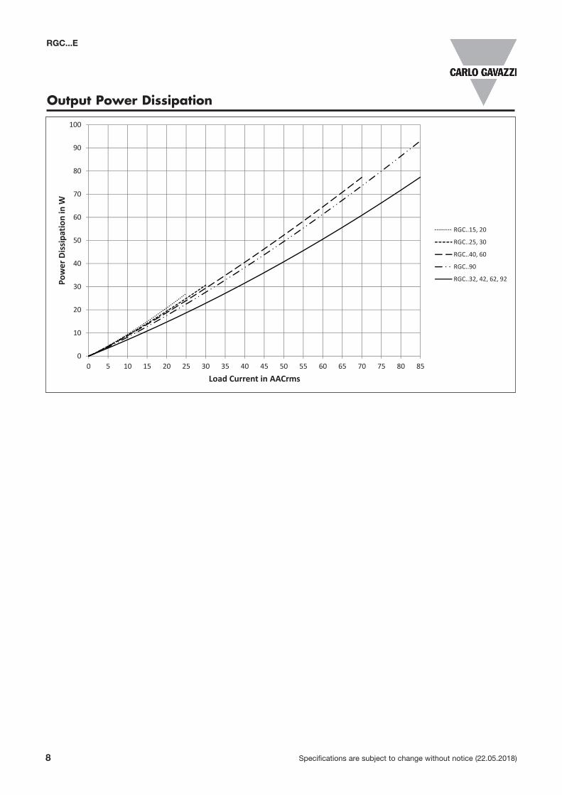
Output Power Dissipation
0
10
20
30
40
50
60
70
80
90
100
0 5 10 15 20 25 30 35 40 45 50 55 60 65 70 75 80 85
Power Dissipa
tion in W
Load Current in AACrms
RGC..15, 20
RGC..25, 30
RGC..40, 60
RGC..90
RGC..32, 42, 62, 92
RGC...E
Specifications are subject to change without notice (22.05.2018) 9
RGC...E
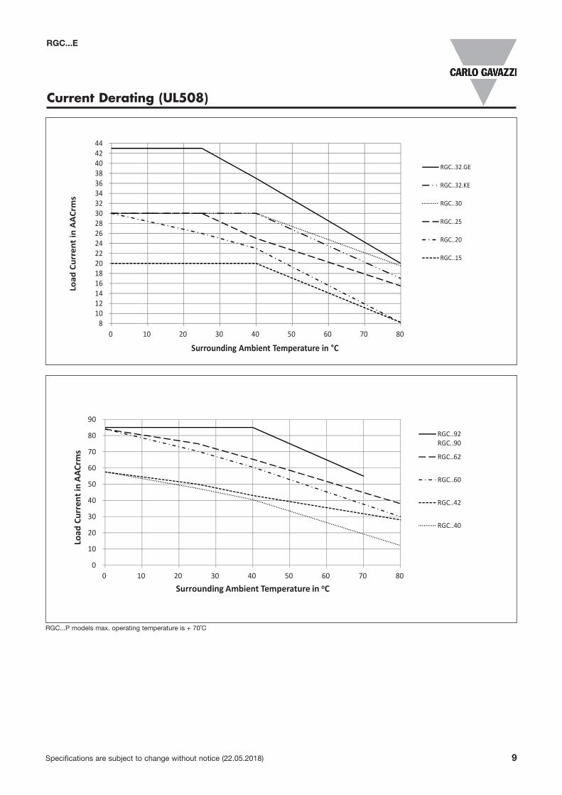
Current Derating (UL508)
RGC...P models max. operating temperature is + 70˚C
8101214161820222426283032343638404244
0 10 20 30 40 50 60 70 80
Load
Current in
AACrms
Surrounding Ambient Temperature in °C
RGC..32.GE
RGC..32.KE
RGC..30
RGC..25
RGC..20
RGC..15
0
10
20
30
40
50
60
70
80
90
0 10 20 30 40 50 60 70 80
Load
Current in
AAC
rms
Surrounding Ambient Temperature in oC
RGC..92RGC..90
RGC..62
RGC..60
RGC..42
RGC..40
10 Specifications are subject to change without notice (22.05.2018)
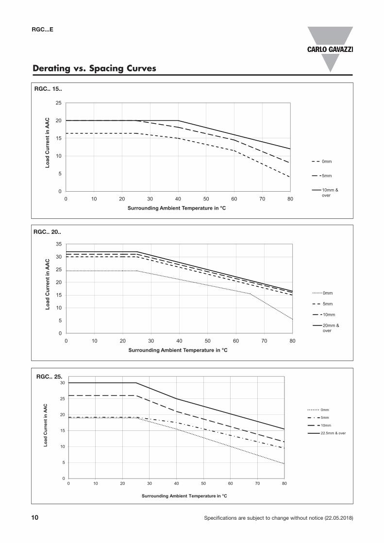
Derating vs. Spacing Curves
RGC...E
15
20
25
ent i
n A
AC
0
5
10
0 10 20 30 40 50 60 70 80
Load
Cur
re
Surrounding Ambient Temperature in °C
0mm
5mm
10mm &over
20
25
30
35
ent i
n A
AC
0mm
5mm
0
5
10
15
20
0 10 20 30 40 50 60 70 80
Load
Cur
re
Surrounding Ambient Temperature in °C
5mm
10mm
20mm & over
0
5
10
15
20
25
30
0 10 20 30 40 50 60 70 80
Load
Cur
rent
in A
AC
Surrounding Ambient Temperature in °C
0mm
5mm
10mm
22.5mm & over
RGC.. 15..
RGC.. 20..
RGC.. 25.
Specifications are subject to change without notice (22.05.2018) 11
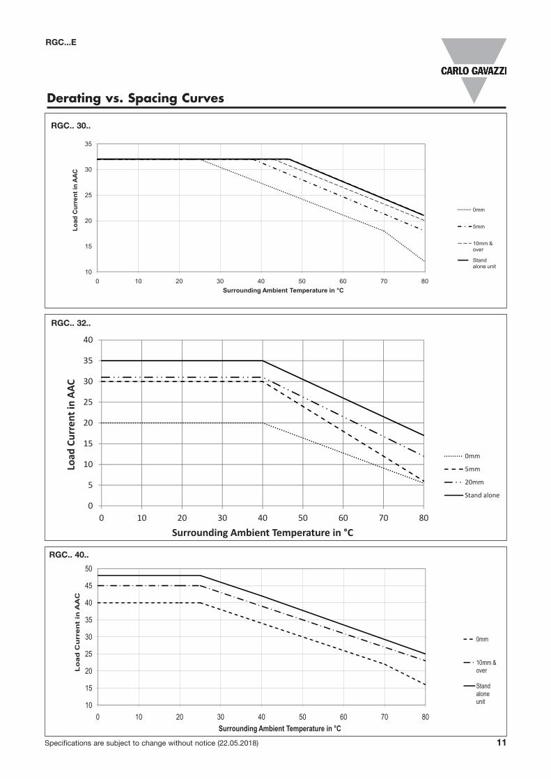
Derating vs. Spacing Curves
RGC...E
25
30
35
nt in
AA
C
0mm
10
15
20
25
0 10 20 30 40 50 60 70 80
Load
Cur
ren
Surrounding Ambient Temperature in °C
5mm
10mm & over
Stand alone unit
RGC.. 30..
35
40
45
50
nt
in A
AC
0mm
10mm &
10
15
20
25
30
0 10 20 30 40 50 60 70 80
Lo
ad C
urr
e
Surrounding Ambient Temperature in °C
over
Stand alone unit
RGC.. 40..
0
5
10
15
20
25
30
35
40
0 10 20 30 40 50 60 70 80
Load
Current in
AAC
Surrounding Ambient Temperature in °C
0mm
5mm
20mm
Stand alone
RGC.. 32..
0
5
10
15
20
25
30
35
40
0 10 20 30 40 50 60 70 80
Load
Current in
AAC
Surrounding Ambient Temperature in °C
0mm
5mm
20mm
Stand alone
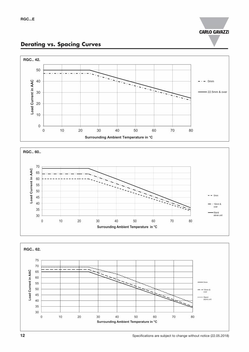
12 Specifications are subject to change without notice (22.05.2018)
Derating vs. Spacing Curves
RGC...E
55
60
65
70
ent
in A
AC
0mm
30
35
40
45
50
55
0 10 20 30 40 50 60 70 80
Lo
ad C
urr
e
Surrounding Ambient Temperature in °C
10mm & over
Stand alone unit
RGC.. 60..
RGC.. 62.
RGC.. 42.
Specifications are subject to change without notice (22.05.2018) 13
75
80
85
90
ent
in A
AC
0mm
50
55
60
65
70
5
0 10 20 30 40 50 60 70
Lo
ad C
urr
e
Surrounding Ambient Temperature in °C
10mm & over
Stand alone unit
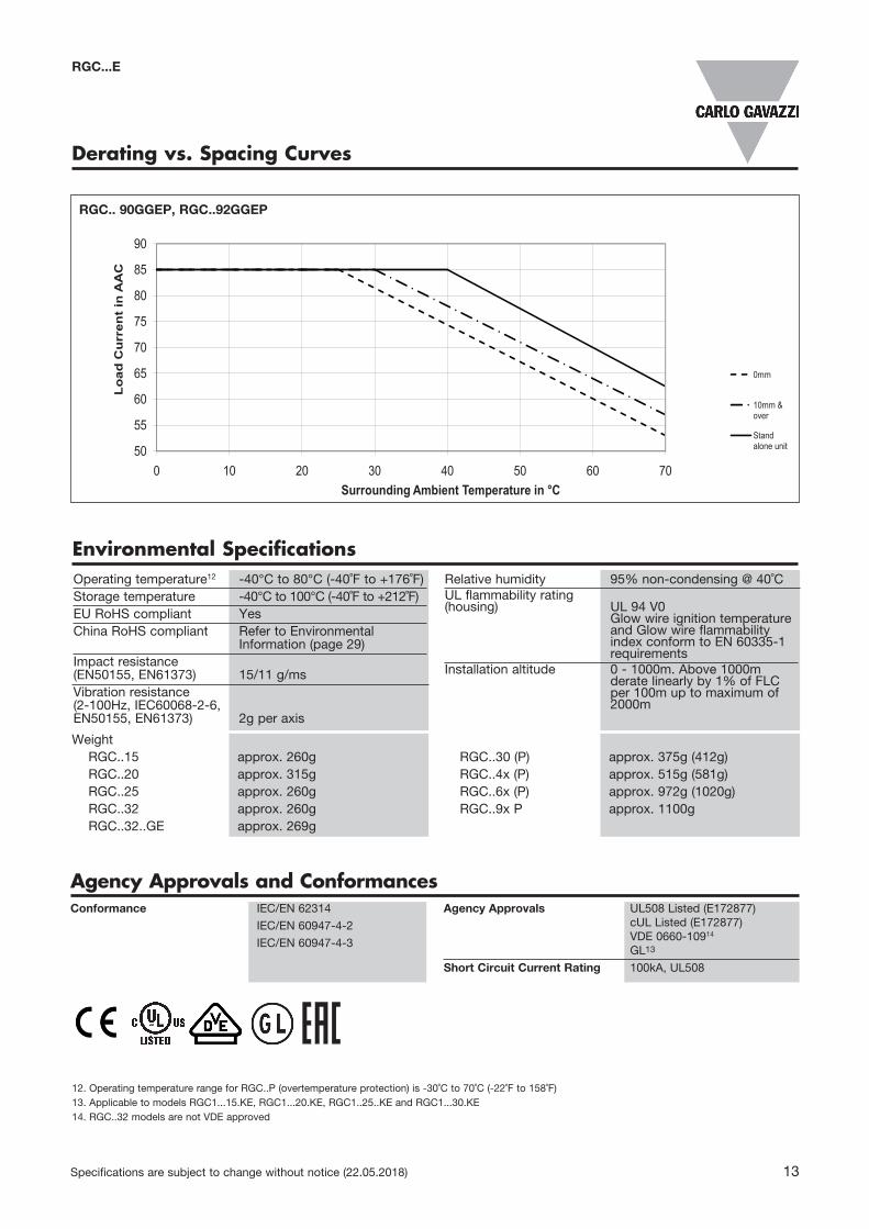
RGC.. 90GGEP, RGC..92GGEP
Derating vs. Spacing Curves
Conformance IEC/EN 62314
IEC/EN 60947-4-2
IEC/EN 60947-4-3
Agency Approvals UL508 Listed (E172877) cUL Listed (E172877) VDE 0660-10914 GL13
Short Circuit Current Rating 100kA, UL508
Agency Approvals and Conformances
12. Operating temperature range for RGC..P (overtemperature protection) is -30˚C to 70˚C (-22˚F to 158˚F)13. Applicable to models RGC1...15.KE, RGC1...20.KE, RGC1..25..KE and RGC1...30.KE14. RGC..32 models are not VDE approved
RGC...E
Environmental SpecificationsOperating temperature12 -40°C to 80°C (-40˚F to +176˚F)Storage temperature -40°C to 100°C (-40˚F to +212˚F)EU RoHS compliant YesChina RoHS compliant Refer to Environmental Information (page 29)Impact resistance (EN50155, EN61373) 15/11 g/msVibration resistance (2-100Hz, IEC60068-2-6, EN50155, EN61373) 2g per axis
Relative humidity 95% non-condensing @ 40˚CUL flammability rating (housing) UL 94 V0 Glow wire ignition temperature and Glow wire flammability index conform to EN 60335-1 requirementsInstallation altitude 0 - 1000m. Above 1000m derate linearly by 1% of FLC per 100m up to maximum of 2000m
Weight RGC..15 approx. 260g RGC..20 approx. 315g RGC..25 approx. 260g RGC..32 approx. 260g RGC..32..GE approx. 269g
RGC..30 (P) approx. 375g (412g) RGC..4x (P) approx. 515g (581g) RGC..6x (P) approx. 972g (1020g) RGC..9x P approx. 1100g
14 Specifications are subject to change without notice (22.05.2018)
RGC...E
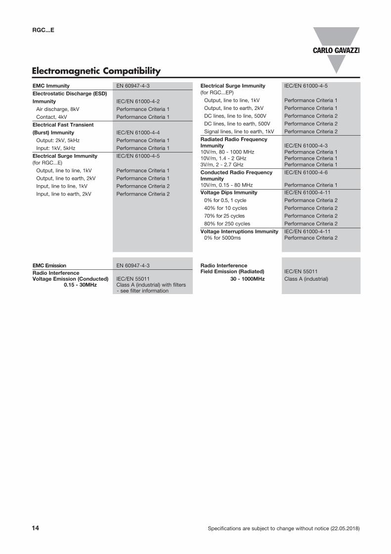
EMC Immunity EN 60947-4-3
Electrostatic Discharge (ESD) Immunity IEC/EN 61000-4-2
Air discharge, 8kV Performance Criteria 1
Contact, 4kV Performance Criteria 1
Electrical Fast Transient (Burst) Immunity IEC/EN 61000-4-4
Output: 2kV, 5kHz Performance Criteria 1
Input: 1kV, 5kHz Performance Criteria 1
Electrical Surge Immunity IEC/EN 61000-4-5 (for RGC...E)
Output, line to line, 1kV Performance Criteria 1
Output, line to earth, 2kV Performance Criteria 1
Input, line to line, 1kV Performance Criteria 2
Input, line to earth, 2kV Performance Criteria 2
Electrical Surge Immunity IEC/EN 61000-4-5 (for RGC...EP)
Output, line to line, 1kV Performance Criteria 1
Output, line to earth, 2kV Performance Criteria 1
DC lines, line to line, 500V Performance Criteria 2
DC lines, line to earth, 500V Performance Criteria 2
Signal lines, line to earth, 1kV Performance Criteria 2
Radiated Radio Frequency Immunity IEC/EN 61000-4-3 10V/m, 80 - 1000 MHz Performance Criteria 1 10V/m, 1.4 - 2 GHz Performance Criteria 1 3V/m, 2 - 2.7 GHz Performance Criteria 1
Conducted Radio Frequency IEC/EN 61000-4-6 Immunity 10V/m, 0.15 - 80 MHz Performance Criteria 1 Voltage Dips Immunity IEC/EN 61000-4-11
0% for 0.5, 1 cycle Performance Criteria 2
40% for 10 cycles Performance Criteria 2
70% for 25 cycles Performance Criteria 2
80% for 250 cycles Performance Criteria 2
Voltage Interruptions Immunity IEC/EN 61000-4-11 0% for 5000ms Performance Criteria 2
EMC Emission EN 60947-4-3Radio Interference Voltage Emission (Conducted) IEC/EN 55011 0.15 - 30MHz Class A (industrial) with filters - see filter information
Radio Interference Field Emission (Radiated) IEC/EN 55011 30 - 1000MHz Class A (industrial)
Electromagnetic Compatibility
Specifications are subject to change without notice (22.05.2018) 15
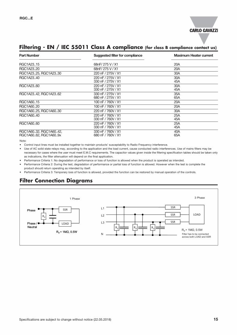
Note:• Control input lines must be installed together to maintain products’ susceptability to Radio Frequency interference.• Use of AC solid state relays may, according to the application and the load current, cause conducted radio interferences. Use of mains filters may be necessary for cases where the user must meet E.M.C requirements. The capacitor values given inside the filtering specification tables should be taken only as indications, the filter attenuation will depend on the final application.• Performance Criteria 1: No degradation of performance or loss of function is allowed when the product is operated as intended.• Performance Criteria 2: During the test, degradation of performance or partial loss of function is allowed. However when the test is complete the product should return operating as intended by itself.• Performance Criteria 3: Temporary loss of function is allowed, provided the function can be restored by manual operation of the controls.
Filtering - EN / IEC 55011 Class A compliance (for class B compliance contact us)
Part Number Suggested filter for compliance Maximum Heater current
RGC1A23..15 68nF/ 275 V / X1 20ARGC1A23..20 68nF/ 275 V / X1 20ARGC1A23..25, RGC1A23..30 220 nF / 275V / X1 30ARGC1A23..40 220 nF / 275V / X1 30A 330 nF / 275V / X1 45ARGC1A23..60 220 nF / 275V / X1 30A 330 nF / 275V / X1 45A RGC1A23..42, RGC1A23..62 330 nF / 275V / X1 35A 680 nF / 275V / X1 65ARGC1A60..15 100 nF / 760V / X1 20ARGC1A60..20 100 nF / 760V / X1 20A RGC1A60..25, RGC1A60..30 220 nF / 760V / X1 30A RGC1A60..40 220 nF / 760V / X1 25A 330 nF / 760V / X1 45ARGC1A60..60 220 nF / 760V / X1 25A 330 nF / 760V / X1 45ARGC1A60..32, RGC1A60..42, 330 nF / 760V / X1 40A RGC1A60..62, RGC1A60..9x 680 nF / 760V / X1 65A
1 Phase 3 Phase
Filter Connection Diagrams
L1
L2
L3
Rd = 1MΩ, 0.5WN Filter has to be connected
across both LOAD and SSR
SSR
Rd
SSR
SSR
LOAD
RdRd
RGC...E
16 Specifications are subject to change without notice (22.05.2018)
RGC...E
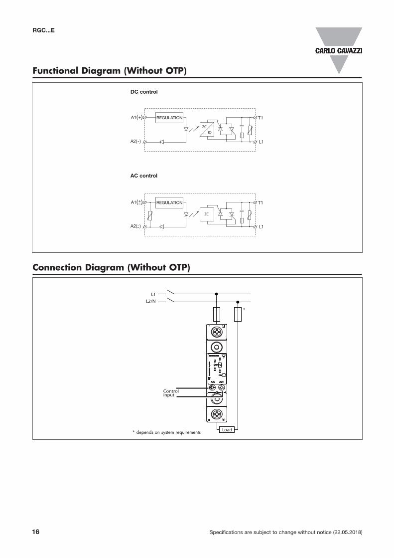
Functional Diagram (Without OTP)
Connection Diagram (Without OTP)
Load
Controlinput
L1L2/N
*
Load
L1L2/N
*
1
2
L1
T1
hctiw
Setat
Sdi lo
SG
R
FAULT
CONTROL
A1
A2GNDGND
SUPPLYALARMALARM
11 + 12 -
* depends on system requirements
A1( )
A2( )
+~ T1
L1
REGULATION
-~
ZC
A1( )
A2( )
+ T1
L1
REGULATION
-
ZCIO
DC control
AC control
Specifications are subject to change without notice (22.05.2018) 17
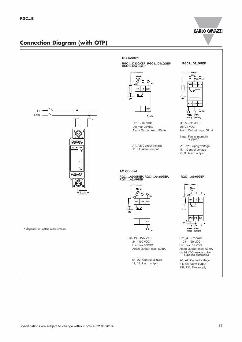
Connection Diagram (with OTP)
RGC1...D30GKEP, RGC1...D4xGGEP, RGC1...D6xGGEP
RGC1...D9xGGEP
Uc: 24 - 275 VAC 24 - 190 VDC Ua: max 35VDC Alarm Output: max. 50mA
Uc: 24 - 275 VAC 24 - 190 VDC Ua: max. 35 VDC Alarm Output: max. 50mA Uf: 24 VDC (needs to be supplied externally)
Uc: 5 - 32 VDCUa: max 35VDCAlarm Output: max. 50mA
Uc: 5 - 32 VDCUs: 24 VDCAlarm Output: max. 50mA
RGC1...A30GKEP, RGC1...A4xGGEP, RGC1...A6xGGEP
RGC1...A9xGGEP
Load
Controlinput
L1L2/N
*
Load
L1L2/N
*
1
2
L1
T1
hctiw
Setat
Sdi lo
SG
R
FAULT
CONTROL
A1
A2GNDGND
SUPPLYALARMALARM
11 + 12 -
* depends on system requirements
DC Control
AC Control
Note: Fan is internally supplied
A1, A2: Control voltage11, 12: Alarm output
A1, A2: Control voltage11, 12: Alarm outputIN2, IN3: Fan supply
A1, A2: Control voltage11, 12: Alarm output
A1, A2: Supply voltageIN1: Control voltageOUT: Alarm output
RGC...E
18 Specifications are subject to change without notice (22.05.2018)
RGC...E
17.8 98.551
35.59.5
17.8
9.5
5
3.2
35.545.5
5
3.2
109.5
92
106
98 90
106
98 90
43.8
43.8
hcti
wS
etat
S dil
oS
GR ON
A1 L1
T1A2
A1 A2
1
2
L1
T1
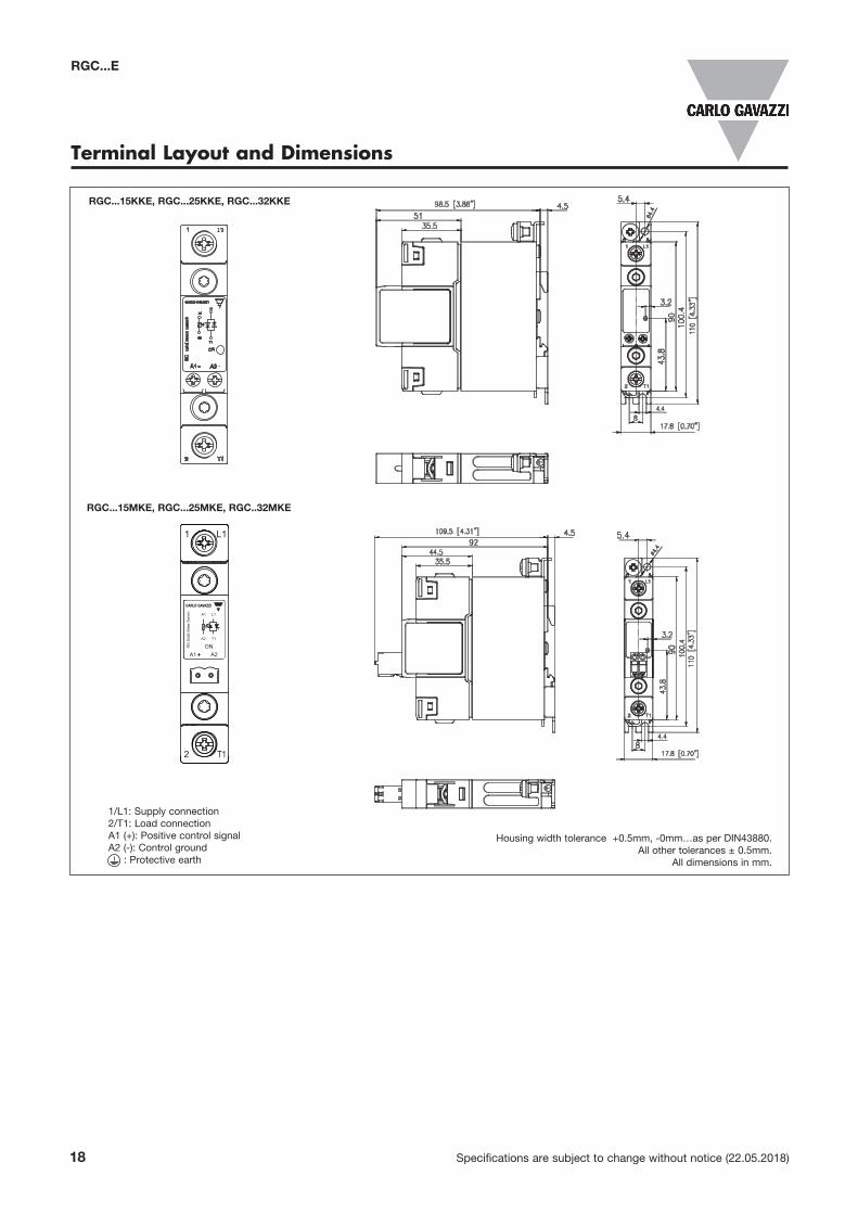
Terminal Layout and Dimensions
Housing width tolerance +0.5mm, -0mm…as per DIN43880.All other tolerances ± 0.5mm.
All dimensions in mm.
1/L1: Supply connection2/T1: Load connectionA1 (+): Positive control signalA2 (-): Control ground : Protective earth
RGC...15KKE, RGC...25KKE, RGC...32KKE
RGC...15MKE, RGC...25MKE, RGC..32MKE
Specifications are subject to change without notice (22.05.2018) 19
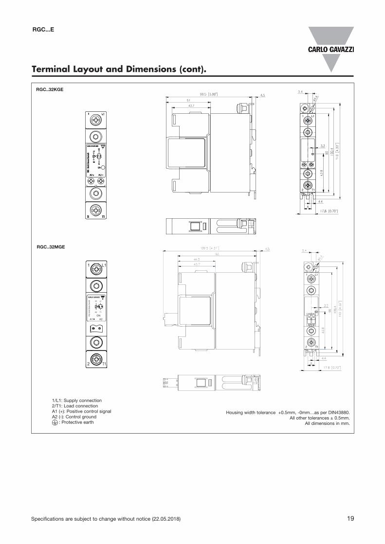
Terminal Layout and Dimensions (cont).
RGC..32KGE
T12
L11
RGC..32MGE
17.8 98.551
35.59.5
17.8
9.5
5
3.2
35.545.5
5
3.2
109.5
92
106
98 90
106
98 90
43.8
43.8
hcti
wS
etat
S dil
oS
GR ON
A1 L1
T1A2
A1 A2
1
2
L1
T1
17.8 98.551
35.59.5
17.8
9.5
5
3.2
35.545.5
5
3.2
109.5
92
106
98 90
106
98 90
43.8
43.8
hcti
wS
etat
S dil
oS
GR ON
A1 L1
T1A2
A1 A2
1
2
L1
T1
Housing width tolerance +0.5mm, -0mm…as per DIN43880.All other tolerances ± 0.5mm.
All dimensions in mm.
1/L1: Supply connection2/T1: Load connectionA1 (+): Positive control signalA2 (-): Control ground : Protective earth
RGC...E
20 Specifications are subject to change without notice (22.05.2018)
RGC...E
17.8 13651
35.59.5
17.8
22.59.5 5
3.2
13651
35.5
9.5
5
3.2
35.545.5
5
3.2
17.8
147
129.5
106
98 90
106
98 90
106
98 90
43.8
43.8
43.8
hcti
wS
etat
S dil
oS
GR ON
A1 L1
T1A2
A1 A2
1
2
L1
T1
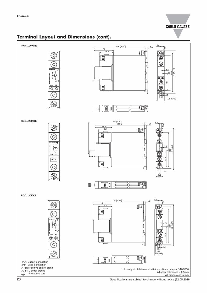
Terminal Layout and Dimensions (cont).
1/L1: Supply connection2/T1: Load connectionA1 (+): Positive control signalA2 (-): Control ground : Protective earth
RGC...20KKE
RGC...20MKE
RGC...30KKE
Housing width tolerance +0.5mm, -0mm…as per DIN43880.All other tolerances ± 0.5mm.
All dimensions in mm.
hcti
wS
etat
S dil
oS
GR ON
A1 L1
T1A2
A1 A2
1
2
L1
T1
22.5
9.5
3.2
5
147
129.5
35.613651
43.7
5
3.2
5
3.2
35.6147129.5 27.2
27.2
43.8
1069890
1069890
43.843.8
Specifications are subject to change without notice (22.05.2018) 21
RGC...E
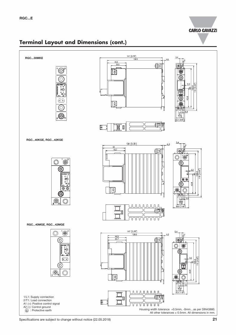
Terminal Layout and Dimensions (cont.)
RGC...30MKE
RGC...40KGE, RGC...42KGE
RGC...40MGE, RGC...42MGE
1/L1: Supply connection2/T1: Load connectionA1 (+): Positive control signalA2 (-): Control ground : Protective earth Housing width tolerance +0.5mm, -0mm…as per DIN43880.
All other tolerances ± 0.5mm. All dimensions in mm.
22 Specifications are subject to change without notice (22.05.2018)
RGC...E
1
2
L1
T1
hcti
wS
etat
S dil
oS
GR
FAULT
CONTROL
A1
A2GNDGND
SUPPLYALARMALARM
11 + 12 -
136 569.135.627.2
3.2
22.5
5
5163
35.578
22.59.5
16378
35.5
17.89.5
1069890
10
69
89
0
10
69
89
0
43.8
5143.7
1
2
L1
T1
hcti
wS
etat
S dil
oS
GR
FAULT
CONTROL
A1
A2GNDGND
SUPPLYALARMALARM
11 + 12 -
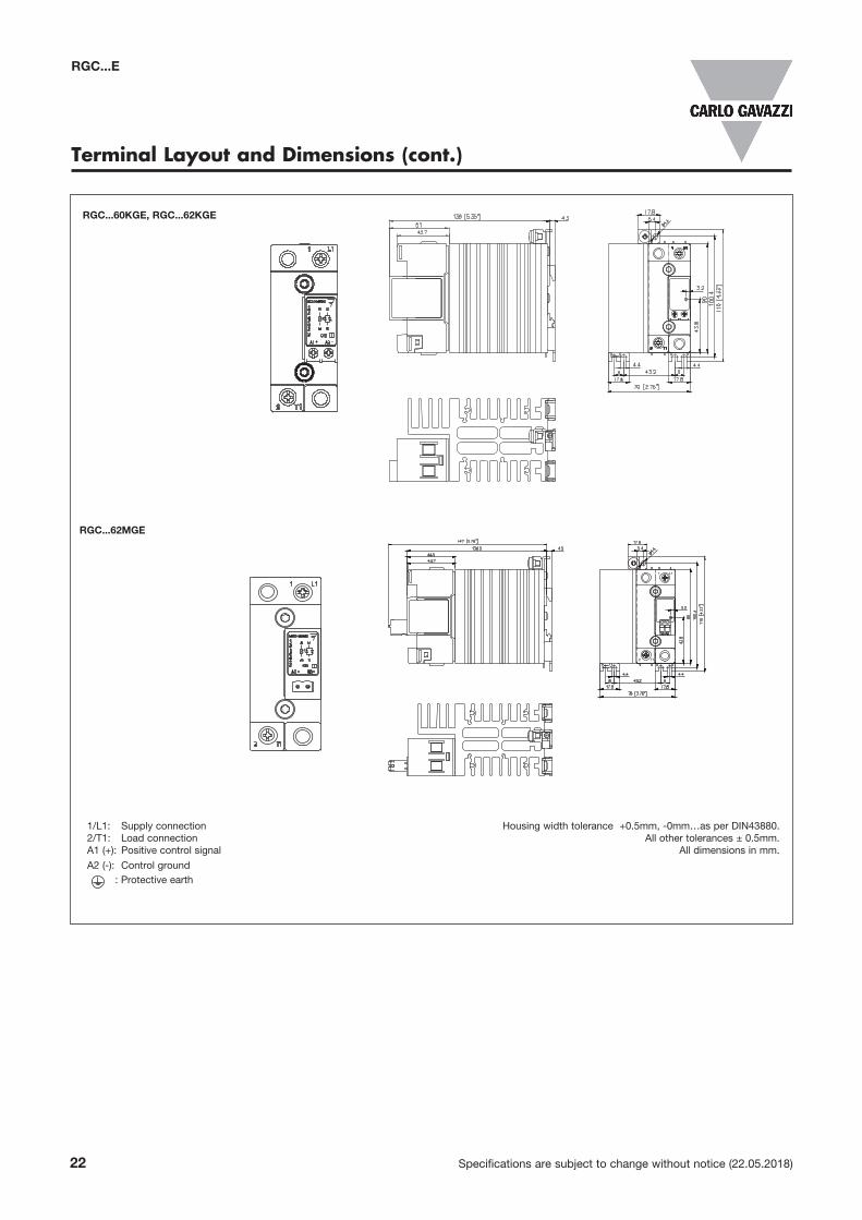
Terminal Layout and Dimensions (cont.)
Housing width tolerance +0.5mm, -0mm…as per DIN43880.All other tolerances ± 0.5mm.
All dimensions in mm.
RGC...62MGE
RGC...60KGE, RGC...62KGE
1/L1: Supply connection2/T1: Load connectionA1 (+): Positive control signal
A2 (-): Control ground : Protective earth
hcti
wS
etat
S dil
oS
GR ON
A1 L1
T1A2
A1 A2
1
2
L1
T1
22.5
9.5
3.2
5
147
129.5
35.613651
43.7
5
3.2
5
3.2
35.6147129.5 27.2
27.2
43.8
1069890
1069890
43.843.8
Specifications are subject to change without notice (22.05.2018) 23
RGC...E
1
2
L1
T1
hcti
wS
etat
S dil
oS
GR
FAULT
CONTROL
A1
A2GNDGND
SUPPLYALARMALARM
11 + 12 -
136 569.135.627.2
3.2
22.5
5
5163
35.578
22.59.5
16378
35.5
17.89.5
1069890
10
69
89
0
10
69
89
0
43.8
5143.7
1
2
L1
T1
hcti
wS
etat
S dil
oS
GR
FAULT
CONTROL
A1
A2GNDGND
SUPPLYALARMALARM
11 + 12 -
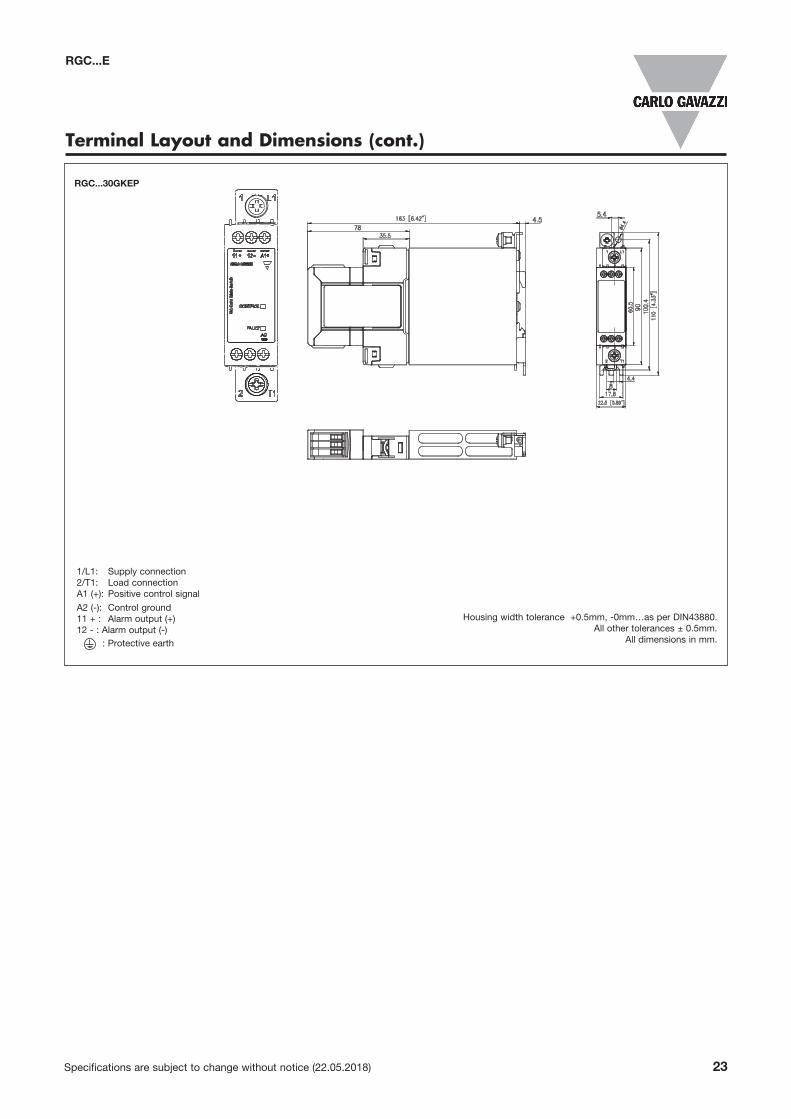
Terminal Layout and Dimensions (cont.)
Housing width tolerance +0.5mm, -0mm…as per DIN43880.All other tolerances ± 0.5mm.
All dimensions in mm.
RGC...30GKEP
1/L1: Supply connection2/T1: Load connectionA1 (+): Positive control signal
A2 (-): Control ground11 + : Alarm output (+)12 - : Alarm output (-) : Protective earth
A1
A2
11+ 12-
A1
A2
11+
IN3IN2
12-
A1
A2
11+
IN3IN2
12-
A1
A2
11+
IN3IN2
12-
A1
A2
11+
IN3IN2
12- A1
A2
11+
IN3IN2
12-
A1
A2
11+
IN3IN2
12-
167.8
535.627.2
69.127.2
69.127.2
1269890
60.5
5163
43.778
5163
7843.7
1069890
106989060.5
16378
43.7
hctiw
S etatS
diloS
GR
FAULT
CONTROL
A1
A2FAN -FAN + GNDGND
SUPPLYCONTROLALARM
OUT
IN3IN2
IN1
24 Specifications are subject to change without notice (22.05.2018)
RGC...E
Terminal Layout and Dimensions (cont.)
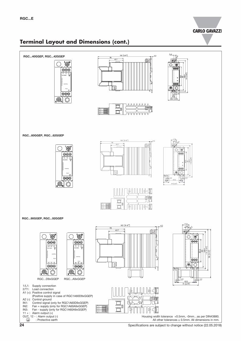
RGC...D9xGGEP RGC...A9xGGEP
1/L1: Supply connection2/T1: Load connectionA1 (+): Positive control signal (Positive supply in case of RGC1A60D9xGGEP)A2 (-): Control groundIN1: Control signal (only for RGC1A60D9xGGEP)IN2: Fan + supply (only for RGC1A60A9xGGEP)IN3: Fan - supply (only for RGC1A60A9xGGEP)11 + : Alarm output (+)OUT, 12 - : Alarm output (-) : Protective earth
RGC...40GGEP, RGC...42GGEP
RGC...60GGEP, RGC...62GGEP
RGC...90GGEP, RGC...92GGEP
Housing width tolerance +0.5mm, -0mm…as per DIN43880.All other tolerances ± 0.5mm. All dimensions in mm.
X XX X
X X
X X
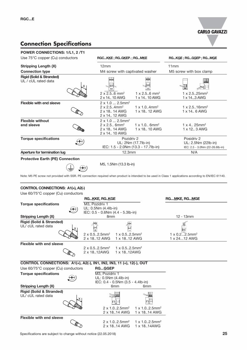
CONTROL CONNECTIONS: A1(+), A2(-) Use 60/75°C copper (Cu) conductors RG...KKE, RG..KGE RG....MKE, RG...MGETorque specifications M3, Pozidriv 1 UL: 0.5Nm (4.4lb-in) IEC: 0.5 - 0.6Nm (4.4 - 5.3lb-in) Stripping Length (X) 8mm 12 - 13mmRigid (Solid & Stranded) UL/ cUL rated data 2 x 0.5..2.5mm2 1 x 0.5..2.5mm2 1 x 0.2...2.5mm2 2 x 18..12 AWG 1 x 18..12 AWG 1 x 24...12 AWGFlexible with end sleeve 2 x 0.5..2.5mm2 1 x 0.5..2.5mm2 2 x 18..12AWG 1 x 18..12AWG
X X
POWER CONNECTIONS: 1/L1, 2 /T1 Use 75°C copper (Cu) conductors RGC...KKE ; RG..GKEP. ; RG...MKE RG...KGE ; RG...GGEP ; RG...MGE Stripping Length (X) 12mm 11mmConnection type M4 screw with captivated washer M5 screw with box clampRigid (Solid & Stranded) UL / cUL rated data 2 x 2.5..6 mm2 1 x 2.5..6 mm2 1 x 2.5..25mm2 2 x 14.. 10 AWG 1 x 14.. 10 AWG 1 x 14...3 AWG Flexible with end sleeve 2 x 1.0 ... 2.5mm2
2 x 2.5..4mm2 1 x 1.0..4mm2 1 x 2.5..16mm2
2 x 18.. 14 AWG 1 x 18.. 12 AWG 1 x 14.. 6 AWG 2 x 14.. 12 AWG Flexible without 2 x 1.0 ... 2.5mm2 end sleeve 2 x 2.5.. 6mm2 1 x 1.0.. 6mm2 1 x 4.. 25mm2 2 x 18.. 14 AWG 1 x 18.. 10 AWG 1 x 12.. 3 AWG 2 x 14.. 10 AWG Torque specifications Pozidriv 2 Posidriv 2 UL: 2Nm (17.7lb-in) UL: 2.5Nm (22lb-in) IEC: 1.5 - 2.0Nm (13.3 - 17.7lb-in) IEC: 2.5 - 3.0Nm (22-26.6lb-in)
Aperture for termination lug 12.3mm N/A
Protective Earth (PE) Connection M5, 1.5Nm (13.3 lb-in)
Connection Specifications
X X
X X
X X
CONTROL CONNECTIONS: A1(+), A2(-), IN1, IN2, IN3, 11 (+), 12(-), OUT Use 60/75°C copper (Cu) conductors RG...GGEP Torque specifications M3, Pozidriv 1 UL: 0.5Nm (4.4lb-in) IEC: 0.4 - 0.5Nm (3.5 - 4.4lb-in) Stripping Length (X) 6mm 6mmRigid (Solid & Stranded) UL/ cUL rated data 2 x 1.0..2.5mm2 1 x 1.0 ..2.5mm2 2 x 18..14 AWG 1 x 18..14 AWG Flexible with end sleeve 2 x 1.0..2.5mm2 1 x 1.0..2.5mm2 2 x 18..14 AWG 1 x 18..14AWG
X X
X X
X X
Specifications are subject to change without notice (22.05.2018) 25
RGC...E
Note: M5 PE screw not provided with SSR. PE connection required when product is intended to be used in Class 1 applications according to EN/IEC 61140.
26 Specifications are subject to change without notice (22.05.2018)
RGC...E
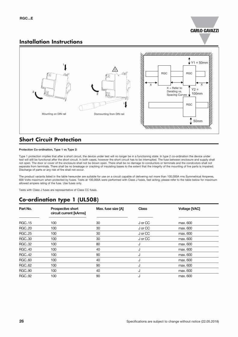
Co-ordination type 1 (UL508)Part No. Prospective short Max. fuse size [A] Class Voltage [VAC] circuit current [kArms]
RGC..15 100 30 J or CC max. 600
RGC..20 100 30 J or CC max. 600
RGC..25 100 30 J or CC max. 600
RGC..30 100 30 J or CC max. 600
RGC..32 100 80 J max. 600
RGC..40 100 40 J max. 600
RGC..42 100 90 J max. 600
RGC..60 100 40 J max. 600
RGC..62 100 90 J max. 600
RGC..90 100 40 J max. 600
RGC..92 100 90 J max. 600
Installation Instructions
Short Circuit Protection
Protection Co-ordination, Type 1 vs Type 2:
Type 1 protection implies that after a short circuit, the device under test will no longer be in a functioning state. In type 2 co-ordination the device under test will still be functional after the short circuit. In both cases, however the short circuit has to be interrupted. The fuse between enclosure and supply shall not open. The door or cover of the enclosure shall not be blown open. There shall be no damage to conductors or terminals and the condcutors shall not separate from terminals. There shall be no breakage or cracking of insulating bases to the extent that the integrity of the mounting of live parts is impaired. Discharge of parts or any risk of fire shall not occur.
The product variants listed in the table hereunder are suitable for use on a circuit capable of delivering not more than 100,000A rms Symmetrical Amperes, 600 Volts maximum when protected by fuses. Tests at 100,000A were performed with Class J fuses, fast acting; please refer to the table below for maximum allowed ampere rating of the fuse. Use fuses only.
Tests with Class J fuses are representative of Class CC fuses.
Y2 =100mm
Y1 = 50mm
50mm
X = 20mm20mm20mm
Mounting on DIN rail Dismounting from DIN rail
X X
Mounting on DIN rail Dismounting from DIN rail
X = Refer to Derating vs. Spacing Curves
RGC RGC
RGC
Specifications are subject to change without notice (22.05.2018) 27
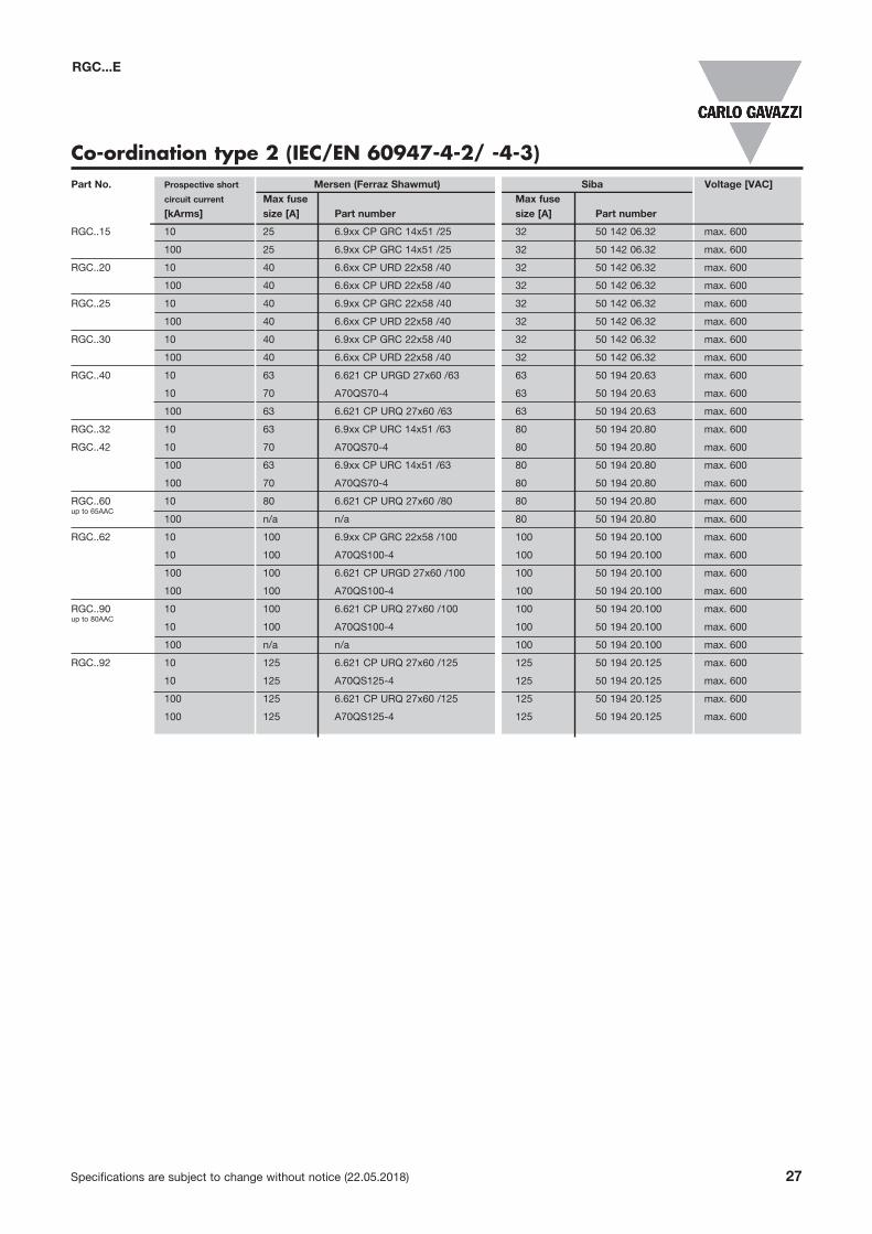
Part No. Prospective short Mersen (Ferraz Shawmut) Siba Voltage [VAC] circuit current Max fuse Max fuse [kArms] size [A] Part number size [A] Part number
RGC..15 10 25 6.9xx CP GRC 14x51 /25 32 50 142 06.32 max. 600
100 25 6.9xx CP GRC 14x51 /25 32 50 142 06.32 max. 600
RGC..20 10 40 6.6xx CP URD 22x58 /40 32 50 142 06.32 max. 600
100 40 6.6xx CP URD 22x58 /40 32 50 142 06.32 max. 600
RGC..25 10 40 6.9xx CP GRC 22x58 /40 32 50 142 06.32 max. 600
100 40 6.6xx CP URD 22x58 /40 32 50 142 06.32 max. 600
RGC..30 10 40 6.9xx CP GRC 22x58 /40 32 50 142 06.32 max. 600
100 40 6.6xx CP URD 22x58 /40 32 50 142 06.32 max. 600
RGC..40 10 63 6.621 CP URGD 27x60 /63 63 50 194 20.63 max. 600
10 70 A70QS70-4 63 50 194 20.63 max. 600
100 63 6.621 CP URQ 27x60 /63 63 50 194 20.63 max. 600
RGC..32 10 63 6.9xx CP URC 14x51 /63 80 50 194 20.80 max. 600
RGC..42 10 70 A70QS70-4 80 50 194 20.80 max. 600
100 63 6.9xx CP URC 14x51 /63 80 50 194 20.80 max. 600
100 70 A70QS70-4 80 50 194 20.80 max. 600
RGC..60 10 80 6.621 CP URQ 27x60 /80 80 50 194 20.80 max. 600up to 65AAC
100 n/a n/a 80 50 194 20.80 max. 600
RGC..62 10 100 6.9xx CP GRC 22x58 /100 100 50 194 20.100 max. 600
10 100 A70QS100-4 100 50 194 20.100 max. 600
100 100 6.621 CP URGD 27x60 /100 100 50 194 20.100 max. 600
100 100 A70QS100-4 100 50 194 20.100 max. 600
RGC..90 10 100 6.621 CP URQ 27x60 /100 100 50 194 20.100 max. 600up to 80AAC
10 100 A70QS100-4 100 50 194 20.100 max. 600
100 n/a n/a 100 50 194 20.100 max. 600
RGC..92 10 125 6.621 CP URQ 27x60 /125 125 50 194 20.125 max. 600
10 125 A70QS125-4 125 50 194 20.125 max. 600
100 125 6.621 CP URQ 27x60 /125 125 50 194 20.125 max. 600
100 125 A70QS125-4 125 50 194 20.125 max. 600
Co-ordination type 2 (IEC/EN 60947-4-2/ -4-3)
RGC...E
28 Specifications are subject to change without notice (22.05.2018)
RGC...E
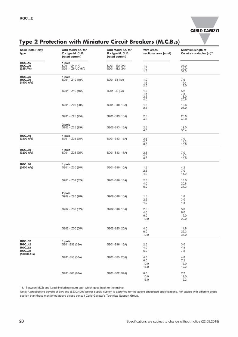
Type 2 Protection with Miniature Circuit Breakers (M.C.B.s)Solid State Relay ABB Model no. for ABB Model no. for Wire cross Minimum length of type Z - type M. C. B. B - type M. C. B. sectional area [mm2] Cu wire conductor [m]16
(rated current) (rated current)
RGC..15 1 pole RGC..20 S201 - Z4 (4A) S201 - B2 (2A) 1.0 21.0(525 A2s) S201 - Z6 UC (6A) S201 - B2 (2A) 1.0 21.0 1.5 31.5 RGC..25 1 pole RGC..30 S201 - Z10 (10A) S201-B4 (4A) 1.0 7.6(1800 A2s) 1.5 11.4 2.5 19.0
S201 - Z16 (16A) S201-B6 (6A) 1.0 5.2 1.5 7.8 2.5 13.0 4.0 20.8 S201 - Z20 (20A) S201-B10 (10A) 1.5 12.6 2.5 21.0 S201 - Z25 (25A) S201-B13 (13A) 2.5 25.0 4.0 40.0 2 pole S202 - Z25 (25A) S202-B13 (13A) 2.5 19.0 4.0 30.4
RGC..40 1 pole (3200 A2s) S201 - Z25 (25A) S201-B13 (13A) 2.5 7.0 4.0 11.2 6.0 16.8
RGC..60 1 pole (3200 A2s) S201 - Z25 (25A) S201-B13 (13A) 2.5 7.0 4.0 11.2 6.0 16.8
RGC..90 1 pole (6600 A2s) S201 - Z20 (20A) S201-B10 (10A) 1.5 4.2 2.5 7.0 4.0 11.2
S201 - Z32 (32A) S201-B16 (16A) 2.5 13.0 4.0 20.8 6.0 31.2 2 pole S202 - Z20 (20A) S202-B10 (10A) 1.5 1.8 2.5 3.0 4.0 4.8 S202 - Z32 (32A) S202-B16 (16A) 2.5 5.0 4.0 8.0 6.0 12.0 10.0 20.0 S202 - Z50 (50A) S202-B25 (25A) 4.0 14.8 6.0 22.2 10.0 37.0
RGC..32 1 pole RGC..42 S201-Z32 (32A) S201-B16 (16A) 2.5 3.0RGC..62 4.0 4.8RGC..92 6.0 7.2(18000 A2s) S201-Z50 (50A) S201-B25 (25A) 4.0 4.8 6.0 7.2 10.0 12.0 16.0 19.2 S201-Z63 (63A) S201-B32 (32A) 6.0 7.2 10.0 12.0 16.0 19.2
16. Between MCB and Load (including return path which goes back to the mains).Note: A prospective current of 6kA and a 230/400V power supply system is assumed for the above suggested specifications. For cables with different cross section than those mentioned above please consult Carlo Gavazzi’s Technical Support Group.
Specifications are subject to change without notice (22.05.2018) 29
RG...P19
Specifications are subject to change without notice (20.02.2017) 13
25
The declaration in this section is prepared in compliance with People’s Republic of China Electronic Industry Standard SJ/T11364-2014: Marking for the Restricted Use of Hazardous Substances in Electronic and Electrical Products.
Part Name Toxic or Harardous Substances and Elements
Lead(Pb)
Mercury(Hg)
Cadmium(Cd)
Hexavalent Chromium
(Cr(Vl))
Polybrominated biphenyls (PBB)
Polybrominated diphenyl ethers
(PBDE)
Power Unit Assembly x O O O O O
O: Indicates that said hazardous substance contained in homogeneous materials fot this part are below the limit require-ment of GB/T 26572.
X: Indicates that said hazardous substance contained in one of the homogeneous materials used for this part is above the limit requirement of GB/T 26572.
Environmental Information
环境特性
这份申明根据中华人民共和国电子工业标准SJ/T11364-2014:标注在电子电气产品中限定使用的有害物质
零件名称 有毒或有害物质与元素
铅(Pb)
汞(Hg)
镉(Cd)
六价铬(Cr(Vl))
多溴化联苯(PBB)
多溴联苯醚(PBDE)
功率单元 x O O O O O
O:此零件所有材料中含有的该有害物低于GB/T 26572的限定。
X: 此零件某种材料中含有的该有害物高于GB/T 26572的限定。
RGC...E
30 Specifications are subject to change without notice (22.05.2018)
RGC...E
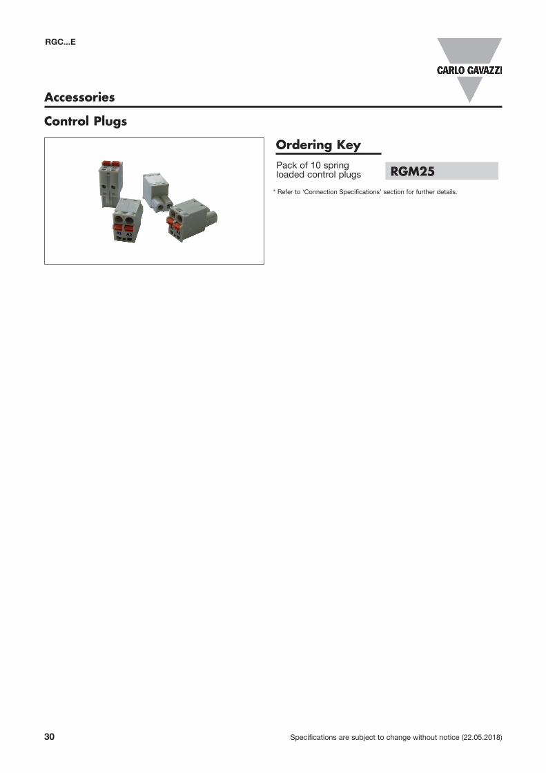
Accessories
* Refer to ‘Connection Specifications’ section for further details.
Control Plugs
Ordering KeyPack of 10 spring loaded control plugs RGM25