HSD Series Rotary Screw Compressors - Kaeser
24
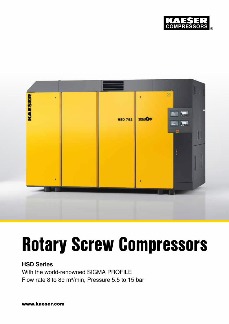
www.kaeser.com HSD Series With the world-renowned SIGMA PROFILE Flow rate 8 to 89 m³/min, Pressure 5.5 to 15 bar Rotary Screw Compressors
-
Upload
khangminh22 -
Category
Documents
-
view
4 -
download
0
Transcript of HSD Series Rotary Screw Compressors - Kaeser
www.kaeser.com
HSD Series With the world-renowned SIGMA PROFILE Flow rate 8 to 89 m³/min, Pressure 5.5 to 15 bar
Rotary Screw Compressors

Up to
usable for heating96 %
Integrated energy savingsThe impressive energy efficiency results from the im-proved specific performance of the further refined SIGMA PROFILE screw airend rotors. In addition, high efficiency IE4 motors provide loss-free 1:1 direct power transmission to the compressor airend. The SIGMA CONTROL 2 com-pressor controller’s master-slave function also allows com-pressor performance to be efficiently adjusted according to actual compressed air demand. Therefore, with selectable control options and through minimised (costly) idling peri-ods, for example, it is possible to save even more energy.
Service-friendly = EfficientSuccessful package design goes far beyond external appearance: it’s what’s on the inside that truly counts, es-pecially when it comes improving efficiency. For example, the fluid separator cartridges can be easily replaced from the top of the package once the roof hood on the outside left-hand side has been lifted up. This not only saves time (and money), but also increases compressor availability.
Perfect team playerHSD series rotary screw compressors are perfect for high-efficiency industrial compressed air stations. Various interfaces of both internal SIGMA CONTROL 2 compres-sor controllers enable easy, secure and efficient network-ing in the KAESER SIGMA NETWORK with the Industrie 4.0-capable SIGMA AIR MANAGER 4.0 management system and/or other centralised control systems.
Stay cool with ETM Powered via an electric motor, the sensor-controlled temperature control valve integrated into the cooling circuit is the heart of the innovative Electronic Thermo Manage-ment (ETM) system. The SIGMA CONTROL 2 monitors intake and compressor temperatures in order to safely prevent condensate formation, even under conditions with higher air humidity. The ETM dynamically controls the fluid temperature, and low fluid temperature enhances energy efficiency. If heat recovery is used, this can be adjusted to better meet the customer’s requirements thanks to two additional ETMs.
Why choose heat recovery?The question should in fact be: Why not? Amazingly, up to 100 % of the (electrical) energy input to a compressor is converted into heat. Up to 96 % of this energy can be recovered and reused for heating purposes. This not only reduces primary energy consumption, but also significantly improves the company’s total energy balance.
With the power of two airendsHSD series
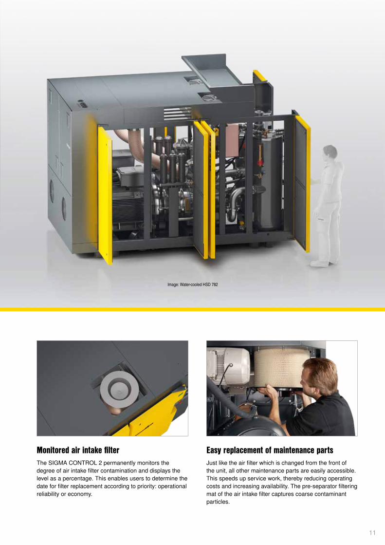
Every water-cooled HSD series rotary screw compressor comprises two compressor units, each of which operates and is controlled independently from the other. System availability is also optimised, which means that performance can be precisely adjusted to suit requirement and costly idling can be kept to an absolute minimum. KAESER’s meticulous attention to detail, such as large double doors to assure excellent component accessibility, external air intake via openings in the roof hood and the use of two large internal fans for optimised cooling performance, ensures user-friendly operation and exceptional ease of maintenance.
2
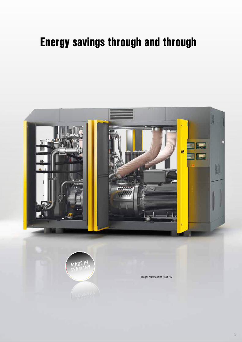
Image: Water-cooled HSD 782
Energy savings through and through
3
4
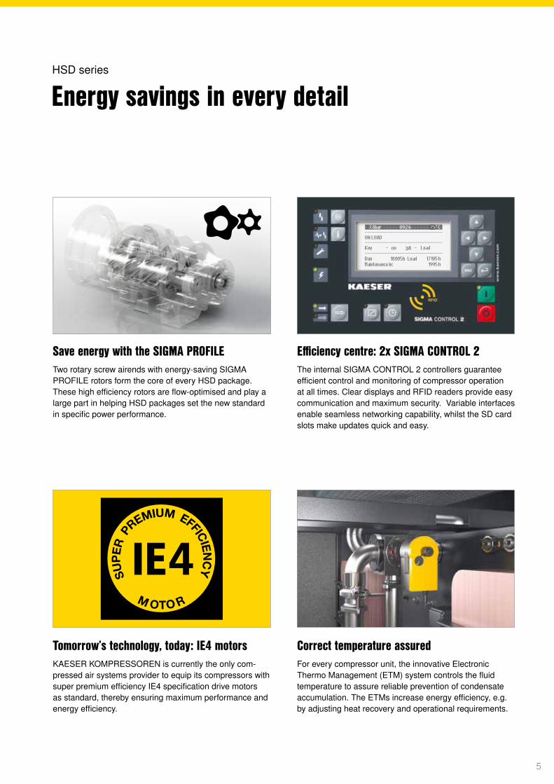
Save energy with the SIGMA PROFILETwo rotary screw airends with energy-saving SIGMA PROFILE rotors form the core of every HSD package. These high efficiency rotors are flow-optimised and play a large part in helping HSD packages set the new standard in specific power performance.
Correct temperature assuredFor every compressor unit, the innovative Electronic Thermo Management (ETM) system controls the fluid temperature to assure reliable prevention of condensate accumulation. The ETMs increase energy efficiency, e.g. by adjusting heat recovery and operational requirements.
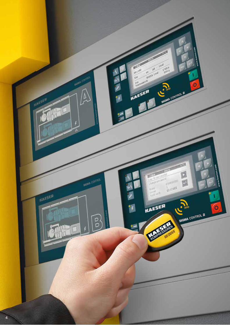
Efficiency centre: 2x SIGMA CONTROL 2The internal SIGMA CONTROL 2 controllers guarantee efficient control and monitoring of compressor operation at all times. Clear displays and RFID readers provide easy communication and maximum security. Variable interfaces enable seamless networking capability, whilst the SD card slots make updates quick and easy.
Tomorrow’s technology, today: IE4 motorsKAESER KOMPRESSOREN is currently the only com-pressed air systems provider to equip its compressors with super premium efficiency IE4 specification drive motors as standard, thereby ensuring maximum performance and energy efficiency.
Energy savings in every detailHSD series
5
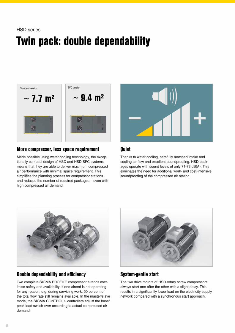
More compressor, less space requirementMade possible using water-cooling technology, the excep-tionally compact design of HSD and HSD SFC systems means that they are able to deliver maximum compressed air performance with minimal space requirement. This simplifies the planning process for compressor stations and reduces the number of required packages – even with high compressed air demand.
System-gentle startThe two drive motors of HSD rotary screw compressors always start one after the other with a slight delay. This results in a significantly lower load on the electricity supply network compared with a synchronous start approach.
QuietThanks to water cooling, carefully matched intake and cooling air flow and excellent soundproofing, HSD pack-ages operate with sound levels of only 71-73 dB(A). This eliminates the need for additional work- and cost-intensive soundproofing of the compressed air station.
Double dependability and efficiencyTwo complete SIGMA PROFILE compressor airends max-imise safety and availability: if one airend is not operating for any reason, e.g. during servicing work, 50 percent of the total flow rate still remains available. In the master/slave mode, the SIGMA CONTROL 2 controllers adjust the base/peak load switch-over according to actual compressed air demand.
Twin pack: double dependabilityHSD series
Standard version SFC version
∼ 9.4 m²∼ 7.7 m²
6
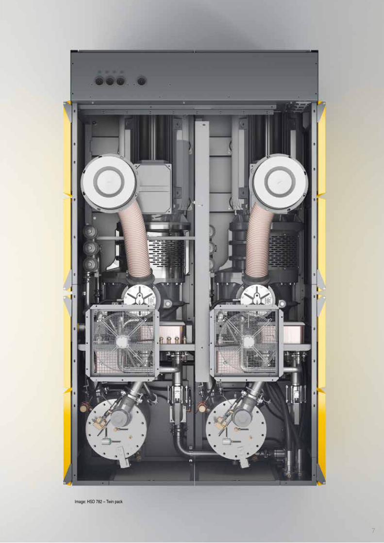
Image: HSD 782 – Twin pack
7
8
Dynamic control+ =
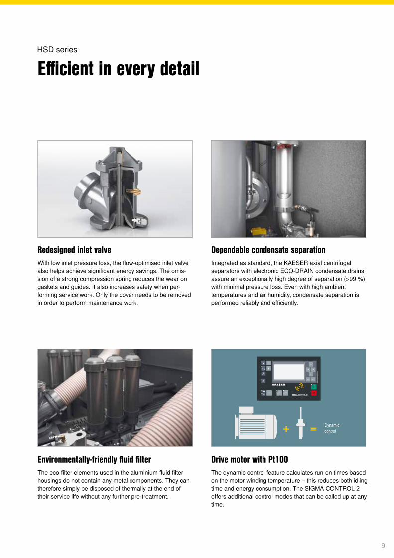
Redesigned inlet valveWith low inlet pressure loss, the flow-optimised inlet valve also helps achieve significant energy savings. The omis-sion of a strong compression spring reduces the wear on gaskets and guides. It also increases safety when per-forming service work. Only the cover needs to be removed in order to perform maintenance work.
Drive motor with Pt100The dynamic control feature calculates run-on times based on the motor winding temperature – this reduces both idling time and energy consumption. The SIGMA CONTROL 2 offers additional control modes that can be called up at any time.
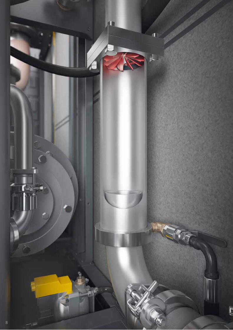
Dependable condensate separationIntegrated as standard, the KAESER axial centrifugal separators with electronic ECO-DRAIN condensate drains assure an exceptionally high degree of separation (>99 %) with minimal pressure loss. Even with high ambient temperatures and air humidity, condensate separation is performed reliably and efficiently.
Environmentally-friendly fluid filterThe eco-filter elements used in the aluminium fluid filter housings do not contain any metal components. They can therefore simply be disposed of thermally at the end of their service life without any further pre-treatment.
Efficient in every detailHSD series
9
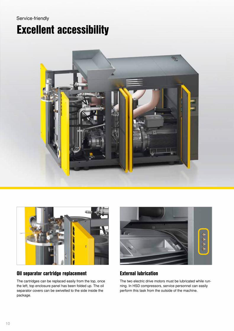
External lubricationThe two electric drive motors must be lubricated while run-ning. In HSD compressors, service personnel can easily perform this task from the outside of the machine.
Oil separator cartridge replacementThe cartridges can be replaced easily from the top, once the left, top enclosure panel has been folded up. The oil separator covers can be swivelled to the side inside the package.
Excellent accessibilityService-friendly
10
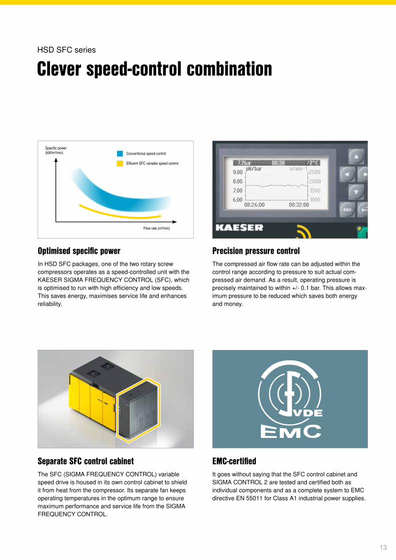
Monitored air intake filterThe SIGMA CONTROL 2 permanently monitors the degree of air intake filter contamination and displays the level as a percentage. This enables users to determine the date for filter replacement according to priority: operational reliability or economy.
Easy replacement of maintenance partsJust like the air filter which is changed from the front of the unit, all other maintenance parts are easily accessible. This speeds up service work, thereby reducing operating costs and increasing availability. The pre-separator filtering mat of the air intake filter captures coarse contaminant particles.
Image: Water-cooled HSD 782
11

12
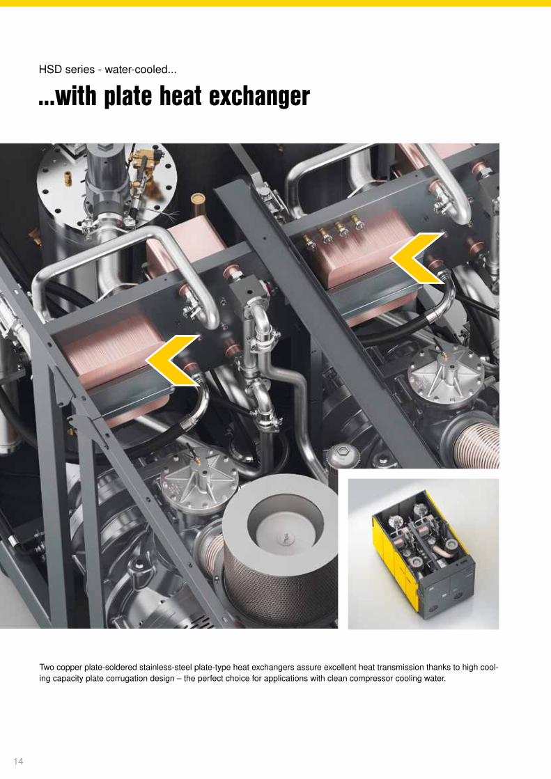
Optimised specific powerIn HSD SFC packages, one of the two rotary screw compressors operates as a speed-controlled unit with the KAESER SIGMA FREQUENCY CONTROL (SFC), which is optimised to run with high efficiency and low speeds. This saves energy, maximises service life and enhances reliability.
EMC-certified It goes without saying that the SFC control cabinet and SIGMA CONTROL 2 are tested and certified both as individual components and as a complete system to EMC directive EN 55011 for Class A1 industrial power supplies.
Separate SFC control cabinetThe SFC (SIGMA FREQUENCY CONTROL) variable speed drive is housed in its own control cabinet to shield it from heat from the compressor. Its separate fan keeps operating temperatures in the optimum range to ensure maximum performance and service life from the SIGMA FREQUENCY CONTROL.
Precision pressure controlThe compressed air flow rate can be adjusted within the control range according to pressure to suit actual com-pressed air demand. As a result, operating pressure is precisely maintained to within +/- 0.1 bar. This allows max-imum pressure to be reduced which saves both energy and money.
Conventional speed control
Efficient SFC variable speed control
Specific power (kW/m³/min)
Flow rate (m³/min)
Clever speed-control combinationHSD SFC series
13
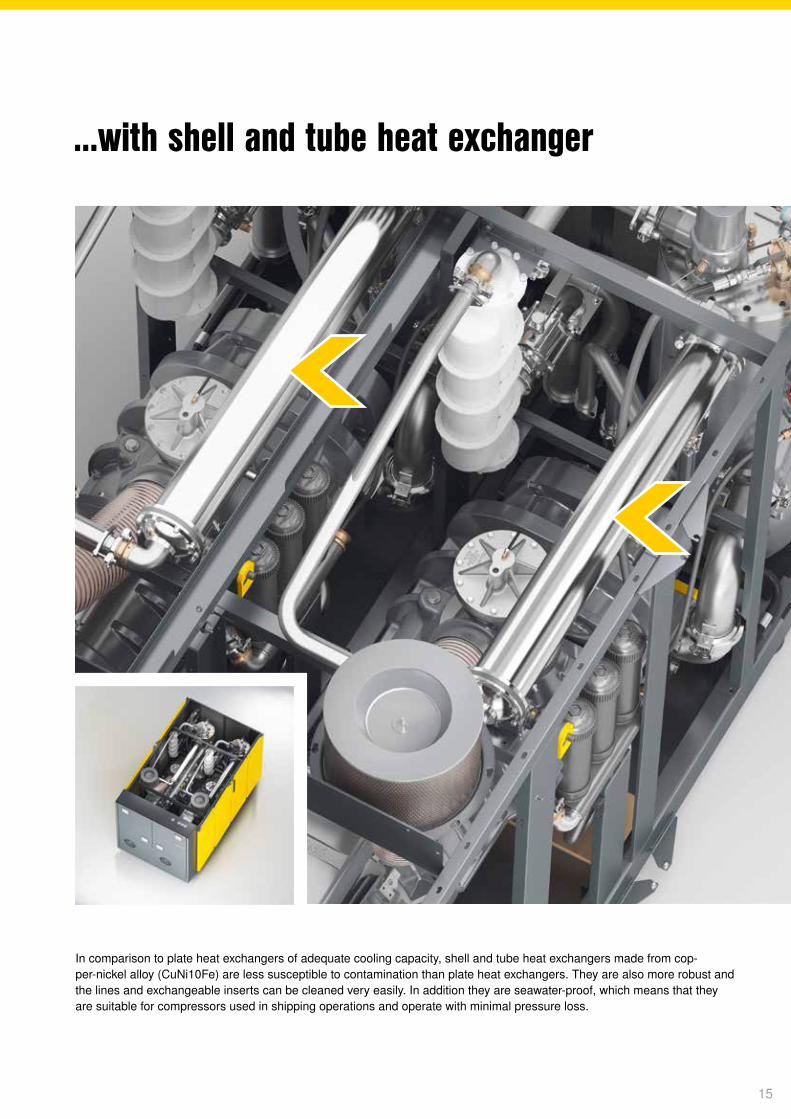
Two copper plate-soldered stainless-steel plate-type heat exchangers assure excellent heat transmission thanks to high cool-ing capacity plate corrugation design – the perfect choice for applications with clean compressor cooling water.
...with plate heat exchangerHSD series - water-cooled...
14
In comparison to plate heat exchangers of adequate cooling capacity, shell and tube heat exchangers made from cop-per-nickel alloy (CuNi10Fe) are less susceptible to contamination than plate heat exchangers. They are also more robust and the lines and exchangeable inserts can be cleaned very easily. In addition they are seawater-proof, which means that they are suitable for compressors used in shipping operations and operate with minimal pressure loss.
...with shell and tube heat exchanger
15
Up to
+70°Chot
Up to
usable for heating96 %
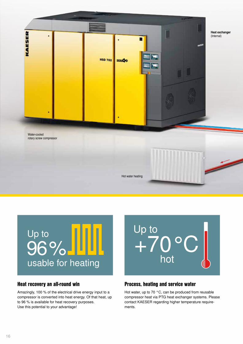
Heat recovery an all-round winAmazingly, 100 % of the electrical drive energy input to a compressor is converted into heat energy. Of that heat, up to 96 % is available for heat recovery purposes. Use this potential to your advantage!
Process, heating and service waterHot water, up to 70 °C, can be produced from reusable compressor heat via PTG heat exchanger systems. Please contact KAESER regarding higher temperature require-ments.
Water-cooled rotary screw compressor
Heat exchanger (Internal)
Hot water heating
16
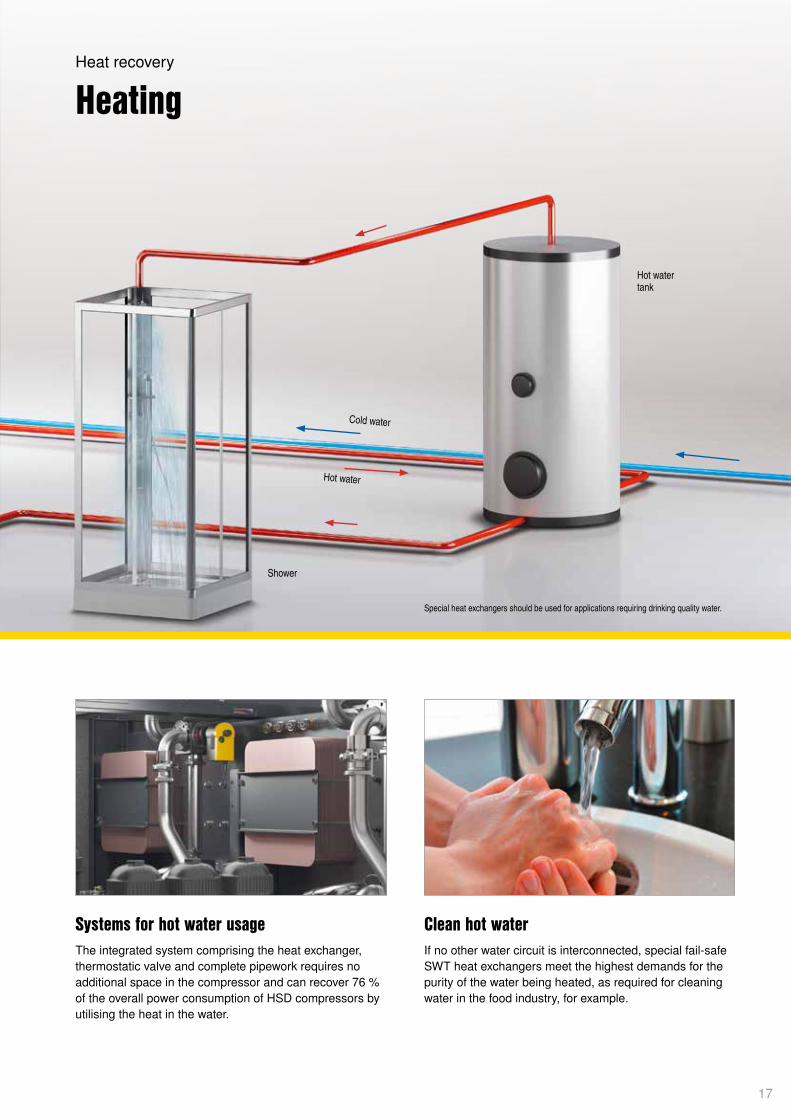
Clean hot waterIf no other water circuit is interconnected, special fail-safe SWT heat exchangers meet the highest demands for the purity of the water being heated, as required for cleaning water in the food industry, for example.
Systems for hot water usageThe integrated system comprising the heat exchanger, thermostatic valve and complete pipework requires no additional space in the compressor and can recover 76 % of the overall power consumption of HSD compressors by utilising the heat in the water.
HeatingHeat recovery
Shower
Hot water tank
Hot water
Cold water
Special heat exchangers should be used for applications requiring drinking quality water.
17
18
ON/OFF
XX°C
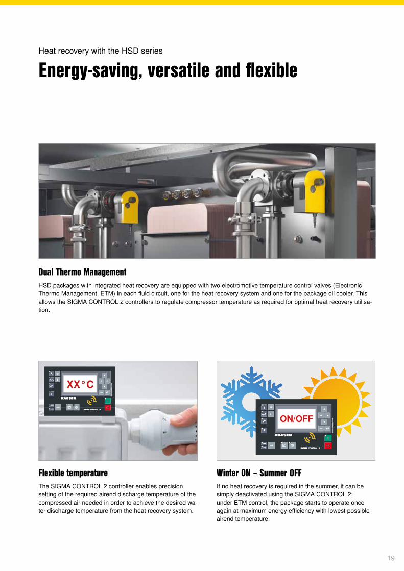
Dual Thermo ManagementHSD packages with integrated heat recovery are equipped with two electromotive temperature control valves (Electronic Thermo Management, ETM) in each fluid circuit, one for the heat recovery system and one for the package oil cooler. This allows the SIGMA CONTROL 2 controllers to regulate compressor temperature as required for optimal heat recovery utilisa-tion.
Winter ON – Summer OFF If no heat recovery is required in the summer, it can be simply deactivated using the SIGMA CONTROL 2: under ETM control, the package starts to operate once again at maximum energy efficiency with lowest possible airend temperature.
Energy-saving, versatile and flexibleHeat recovery with the HSD series
Flexible temperatureThe SIGMA CONTROL 2 controller enables precision setting of the required airend discharge temperature of the compressed air needed in order to achieve the desired wa-ter discharge temperature from the heat recovery system.
19
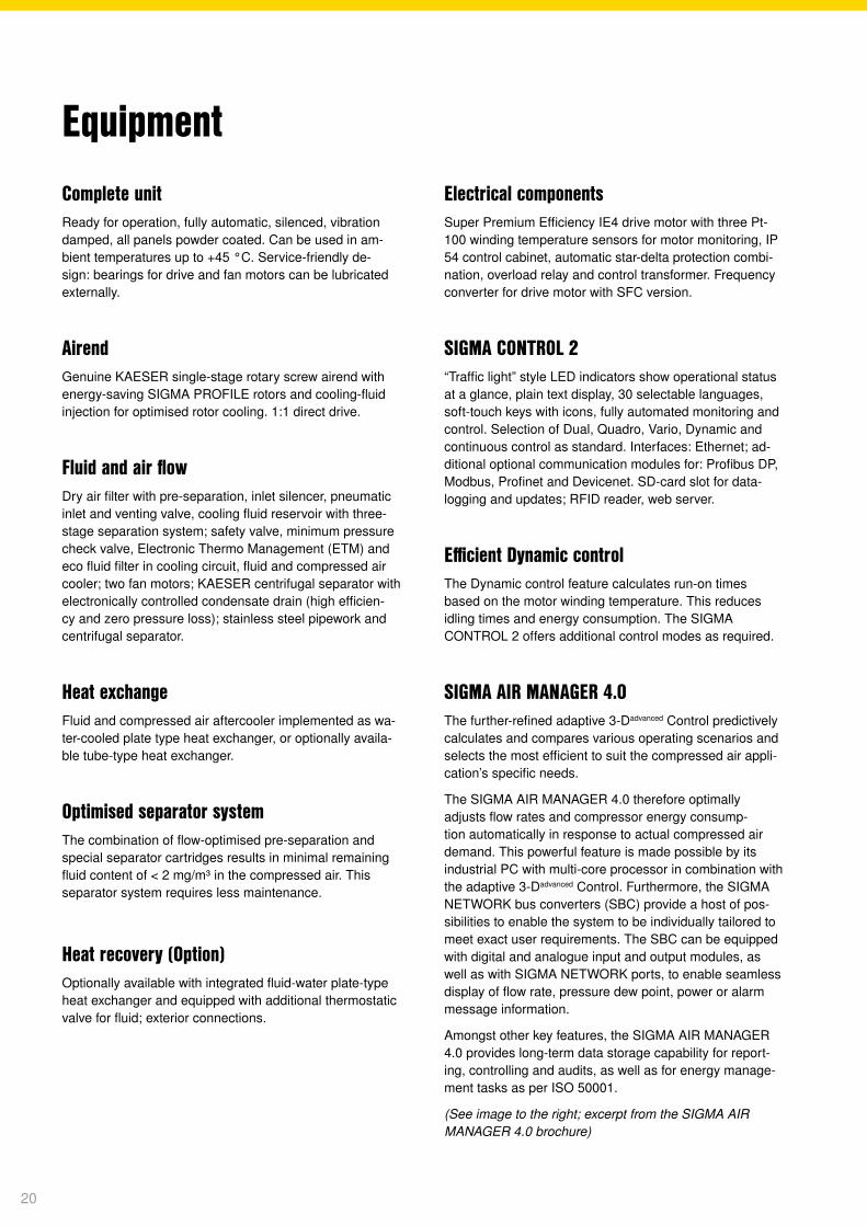
Complete unitReady for operation, fully automatic, silenced, vibration damped, all panels powder coated. Can be used in am-bient temperatures up to +45 °C. Service-friendly de-sign: bearings for drive and fan motors can be lubricated externally.
Airend Genuine KAESER single-stage rotary screw airend with energy-saving SIGMA PROFILE rotors and cooling-fluid injection for optimised rotor cooling. 1:1 direct drive.
Fluid and air flowDry air filter with pre-separation, inlet silencer, pneumatic inlet and venting valve, cooling fluid reservoir with three-stage separation system; safety valve, minimum pressure check valve, Electronic Thermo Management (ETM) and eco fluid filter in cooling circuit, fluid and compressed air cooler; two fan motors; KAESER centrifugal separator with electronically controlled condensate drain (high efficien-cy and zero pressure loss); stainless steel pipework and centrifugal separator.
Heat exchangeFluid and compressed air aftercooler implemented as wa-ter-cooled plate type heat exchanger, or optionally availa-ble tube-type heat exchanger.
Optimised separator systemThe combination of flow-optimised pre-separation and special separator cartridges results in minimal remaining fluid content of < 2 mg/m³ in the compressed air. This separator system requires less maintenance.
Heat recovery (Option)Optionally available with integrated fluid-water plate-type heat exchanger and equipped with additional thermostatic valve for fluid; exterior connections.
EquipmentElectrical componentsSuper Premium Efficiency IE4 drive motor with three Pt-100 winding temperature sensors for motor monitoring, IP 54 control cabinet, automatic star-delta protection combi-nation, overload relay and control transformer. Frequency converter for drive motor with SFC version.
SIGMA CONTROL 2“Traffic light” style LED indicators show operational status at a glance, plain text display, 30 selectable languages, soft-touch keys with icons, fully automated monitoring and control. Selection of Dual, Quadro, Vario, Dynamic and continuous control as standard. Interfaces: Ethernet; ad-ditional optional communication modules for: Profibus DP, Modbus, Profinet and Devicenet. SD-card slot for data- logging and updates; RFID reader, web server.
Efficient Dynamic controlThe Dynamic control feature calculates run-on times based on the motor winding temperature. This reduces idling times and energy consumption. The SIGMA CONTROL 2 offers additional control modes as required.
SIGMA AIR MANAGER 4.0The further-refined adaptive 3-Dadvanced Control predictively calculates and compares various operating scenarios and selects the most efficient to suit the compressed air appli-cation’s specific needs.
The SIGMA AIR MANAGER 4.0 therefore optimally adjusts flow rates and compressor energy consump-tion automatically in response to actual compressed air demand. This powerful feature is made possible by its industrial PC with multi-core processor in combination with the adaptive 3-Dadvanced Control. Furthermore, the SIGMA NETWORK bus converters (SBC) provide a host of pos-sibilities to enable the system to be individually tailored to meet exact user requirements. The SBC can be equipped with digital and analogue input and output modules, as well as with SIGMA NETWORK ports, to enable seamless display of flow rate, pressure dew point, power or alarm message information.
Amongst other key features, the SIGMA AIR MANAGER 4.0 provides long-term data storage capability for report-ing, controlling and audits, as well as for energy manage-ment tasks as per ISO 50001.
(See image to the right; excerpt from the SIGMA AIR MANAGER 4.0 brochure)
20
Control centre
i
Status
Messages
Monitoring
Energy & costs
Control
SAM 4.0 Logic
Time control
Initial start-up
Confi guration
Contact
Compressors
C1 - BSD 75
C2 - BSD 75
C3 - CSD 125
C4 - CSD 125
Dryer
Filter
Air receiver
Condensate
treatment
Station
SIGMA AIR MANAGER 4.0 4 Automatic 6.62 bar
Maintenance
112.6119.07
PowerVolumetric fl ow rate
kWm³/min
Station
C1
C2
C3
C4
D1
D2
F1
F2
R1DHS1
CT1
CD1
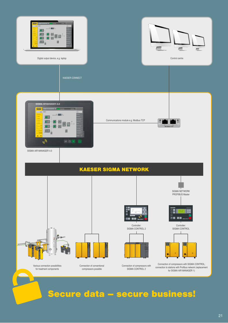
SIGMA AIR MANAGER 4.0
Communications module e.g. Modbus TCP
KAESER CONNECT
Digital output device, e.g. laptop Control centre
Controller: SIGMA CONTROL 2
Controller: SIGMA CONTROL
SIGMA NETWORK PROFIBUS Master
Secure data – secure business!
KAESER SIGMA NETWORK
Various connection possibilities for treatment components
Connection of conventional compressors possible
Connection of compressors with SIGMA CONTROL 2
Connection of compressors with SIGMA CONTROL; connection to stations with Profibus network (replacement
for SIGMA AIR MANAGER 1)
21
Modell Betriebs-überdruck
Volumenstrom *) Gesamtanlage bei Betriebsüberdruck
max. Überdruck
Nennleistung Antriebsmotoren
AbmessungenB x T x H
Anschluss Druckluft
Schalldruck-pegel **)
Masse
bar m³/min bar kW mm dB(A) kg
HSD 662
7.5 66.40 8.5
360 3570 x 2145 x 2350 DN 150 PN 16 71 810010 54.44 12
13 43.72 15
HSD 722
7.5 72.40 8.5
400 3570 x 2145 x 2350 DN 150 PN 16 72 850010 59.48 12
13 47.87 15
HSD 782
7.5 78.40 8.5
450 3570 x 2145 x 2350 DN 150 PN 16 72 860010 65.31 12
13 53.07 15
HSD 842
7.5 84.40 8.5
500 3570 x 2145 x 2350 DN 150 PN 16 73 870010 71.15 12
13 58.27 15
Modell Betriebs-überdruck
Volumenstrom *) Gesamtanlage bei Betriebsüberdruck
max. Überdruck
Nennleistung Antriebsmotor
AbmessungenB x T x H
Anschluss Druckluft
Schalldruck-pegel **)
Masse
bar m³/min bar kW mm dB(A) kg
HSD 662 SFC7.5 10.40 - 66.35 8.5
382 4370 x 2145 x 2350 DN 150 PN 16 73 910010 8.50 - 57.50 12
HSD 782 SFC
7.5 11.90 - 77.80 8.5
410 4370 x 2145 x 2350 DN 150 PN 16 74 960010 10.00 - 65.50 12
13 8.00 - 55.78 15
HSD 842 SFC
7.5 11.90 - 87.30 8.5
515 4370 x 2145 x 2350 DN 150 PN 16 75 1010010 10.00 - 74.44 12
13 8.00 - 63.44 15
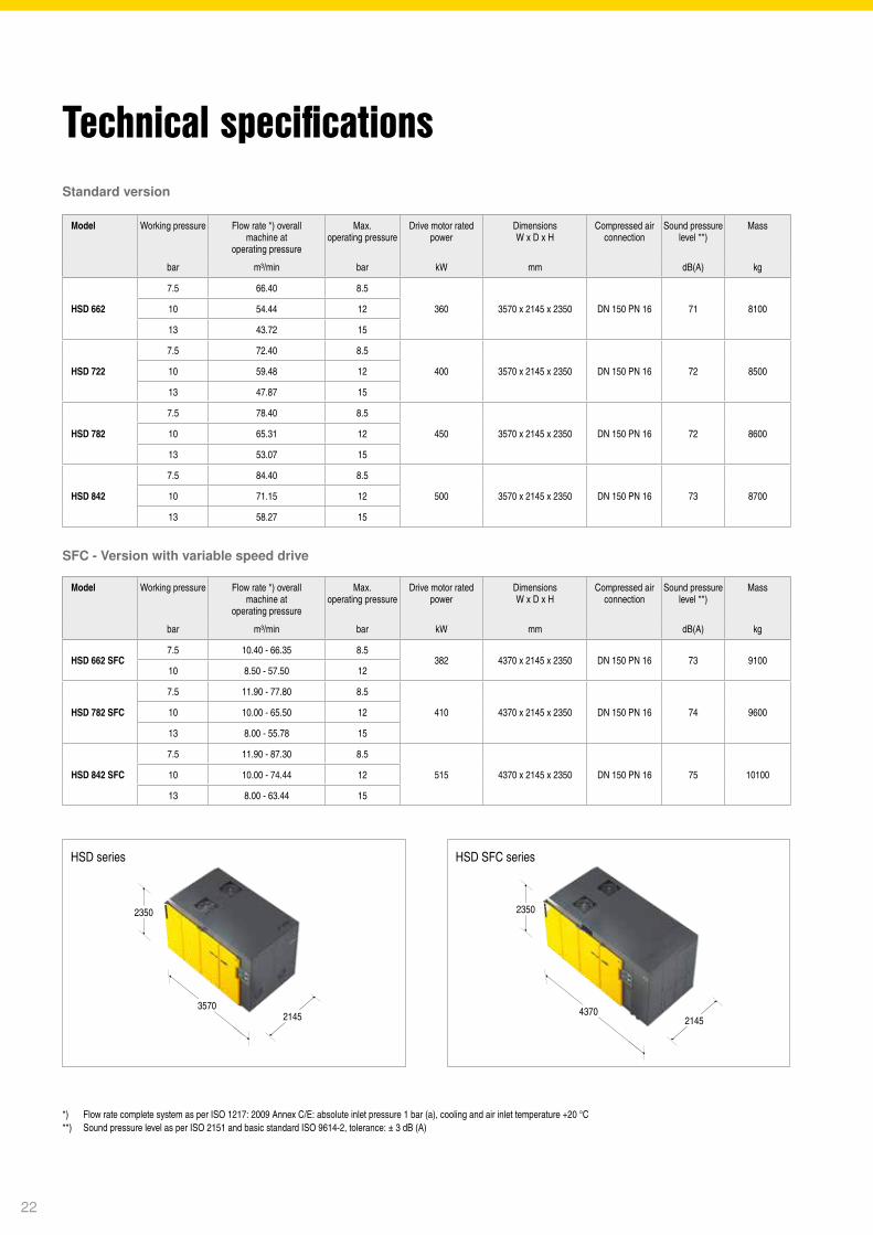
Technical specifications
*) Flow rate complete system as per ISO 1217: 2009 Annex C/E: absolute inlet pressure 1 bar (a), cooling and air inlet temperature +20 °C **) Sound pressure level as per ISO 2151 and basic standard ISO 9614-2, tolerance: ± 3 dB (A)
Model Working pressure Flow rate *) overall machine at
operating pressure
Max.operating pressure
Drive motor rated power
DimensionsW x D x H
Compressed air connection
Sound pressure level **)
Mass
bar m³/min bar kW mm dB(A) kg
Standard version
SFC - Version with variable speed drive
Model Working pressure Flow rate *) overall machine at
operating pressure
Max.operating pressure
Drive motor rated power
DimensionsW x D x H
Compressed air connection
Sound pressure level **)
Mass
bar m³/min bar kW mm dB(A) kg
HSD series HSD SFC series
3570
2350
2145 4370
2350
2145
22
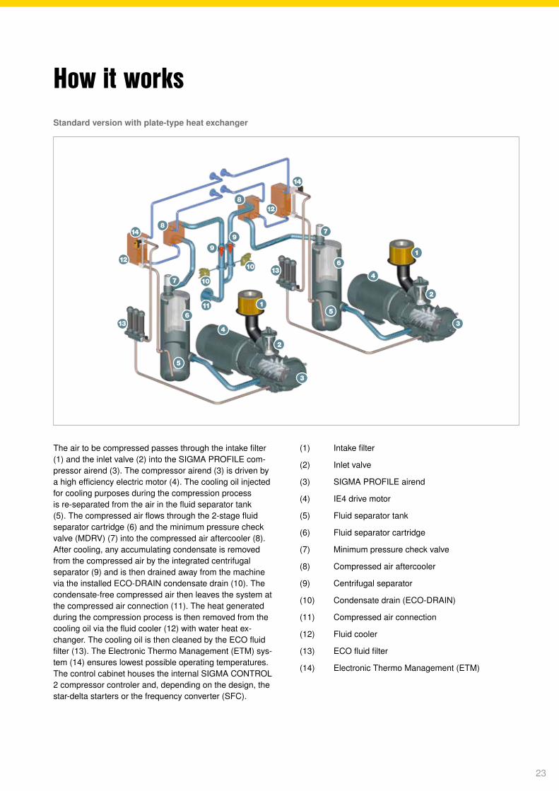
How it works
The air to be compressed passes through the intake filter (1) and the inlet valve (2) into the SIGMA PROFILE com-pressor airend (3). The compressor airend (3) is driven by a high efficiency electric motor (4). The cooling oil injected for cooling purposes during the compression process is re-separated from the air in the fluid separator tank (5). The compressed air flows through the 2-stage fluid separator cartridge (6) and the minimum pressure check valve (MDRV) (7) into the compressed air aftercooler (8). After cooling, any accumulating condensate is removed from the compressed air by the integrated centrifugal separator (9) and is then drained away from the machine via the installed ECO-DRAIN condensate drain (10). The condensate-free compressed air then leaves the system at the compressed air connection (11). The heat generated during the compression process is then removed from the cooling oil via the fluid cooler (12) with water heat ex-changer. The cooling oil is then cleaned by the ECO fluid filter (13). The Electronic Thermo Management (ETM) sys-tem (14) ensures lowest possible operating temperatures. The control cabinet houses the internal SIGMA CONTROL 2 compressor controler and, depending on the design, the star-delta starters or the frequency converter (SFC).
(1) Intake filter
(2) Inlet valve
(3) SIGMA PROFILE airend
(4) IE4 drive motor
(5) Fluid separator tank
(6) Fluid separator cartridge
(7) Minimum pressure check valve
(8) Compressed air aftercooler
(9) Centrifugal separator
(10) Condensate drain (ECO-DRAIN)
(11) Compressed air connection
(12) Fluid cooler
(13) ECO fluid filter
(14) Electronic Thermo Management (ETM)
Standard version with plate-type heat exchanger
23

The world is our homeAs one of the world’s largest compressed air system providers and compressor manufacturers, KAESER KOMPRESSOREN is represented throughout the world by a comprehensive network of branches, subsidiary companies and authorised partners in over 100 countries.
With innovative products and services, KAESER KOMPRESSOREN’s experienced consultants and engineers help customers to enhance their competitive edge by working in close partnership to develop progressive system concepts that continuously push the boundaries of performance and compressed air effi ciency.
Moreover, the decades of knowledge and expertise from this industry-leading system provider are made available to each and every customer via the KAESER group’s global computer network.
These advantages, coupled with KAESER’s worldwide service organisation, ensure that every product operates at the peak of its performance at all times and provides maximum availability.
KAESER KOMPRESSOREN SEP.O. Box 2143 – 96410 Coburg – GERMANY – Tel +49 9561 640-0 – Fax +49 9561 640-130e-mail: [email protected] – www.kaeser.com P-
651/
27ED
Sp
ecific
atio
ns a
re s
ubje
ct to
cha
nge
with
out n
otice
. .3
/19