EEEE Voltage Stability Analysis of Electric Power System with ...
Upload
khangminh22Category
view
0download
0
POWER SYSTEM STABILITY
Prof. M VENKATESWARA RAO
Dept. of EEE,
JNTUA College of Engineering, Kalikiri
Chittoor District, A P, India
Prof. M Venkateswara Rao, Dept. of EEE, JNTUA College of Engineering, Kalikiri, Chittoor District, A P, India

Outline of Presentation
Introduction
Power angle curve
Dynamics Of Synchronous Machine
Swing equation
Analysis of steady state stability
Equal Area Criterion
Methods of improving stability
Previous years GATE Questions
Prof. M Venkateswara Rao, Dept. of EEE, JNTUA College of Engineering, Kalikiri, Chittoor District, A P, India

Introduction (contd…)
A large power system consists of a number of synchronous machines
(or equipments or components) operating in synchronism.
When the system is subjected to some form of disturbance, there is a
tendency for the system to develop forces to bring it to a normal or
stable condition
The term stability refers to stable operation of the synchronous
machines connected to a power system when they are subjected to
sudden disturbances.
Depending on the nature and magnitude of disturbances the stability
studies can be classified in to the following types
1. Steady state stability
2. Transient stability
Prof. M Venkateswara Rao, Dept. of EEE, JNTUA College of Engineering, Kalikiri, Chittoor District, A P, India

Introduction (contd…)
Prof. M Venkateswara Rao, Dept. of EEE, JNTUA College of Engineering, Kalikiri, Chittoor District, A P, India
POWER SYSTEM STABILITY
Static stability
Steady state stability
Dynamic Stability
Transient state stability

Introduction (contd…)
Steady state stability : It is defined as the ability of a power
system to remain stable (i.e., without losing synchronism) for
small disturbances ( gradual changes in load).
Static stability refers to inherent stability that prevails without
the aid of automatic control devices
Dynamic stability refers to artificial stability given to an
inherently unstable system by automatic control devices. It is
concerned with small disturbances lasting for 10 to 30 sec.
The transient stability is defined as the ability of a power
system to remain stable for large disturbances. (such as sudden
change in loads, loss of generations, excitations, transmission
facilities, switching operations and faults).
Prof. M Venkateswara Rao, Dept. of EEE, JNTUA College of Engineering, Kalikiri, Chittoor District, A P, India
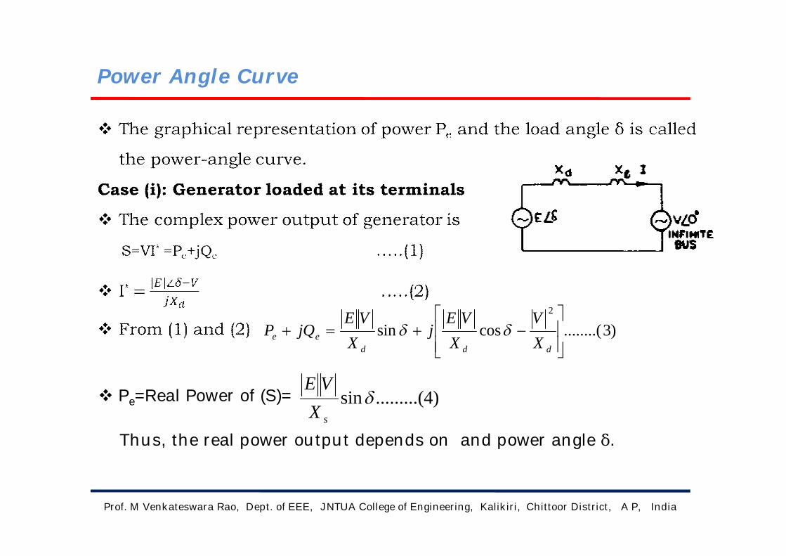
Power Angle Curve
Prof. M Venkateswara Rao, Dept. of EEE, JNTUA College of Engineering, Kalikiri, Chittoor District, A P, India
)3........(cossin2
dddee X
VX
VEj
XVE
jQP
Pe=Real Power of (S)=
Thus, the real power output depends on and power angle δ.
)4.........(sinsXVE

Power Angle Curve (contd…)
Prof. M Venkateswara Rao, Dept. of EEE, JNTUA College of Engineering, Kalikiri, Chittoor District, A P, India
Plotting (4)
As δ is increased beyond 900 ,Pe decreases .
At δ=1800, Pe becomes zero.
Beyond δ=1800 ,Pe becomes negative which implies that the power
flow direction is reversed and the power is supplied from the infinite
bus to the generator.
The positive value of δ (E leading V) applies to generator action and
negative value for δ (E lagging V) applies to the motor action.

Power Angle Curve (contd…)
The max steady-state power transfer occurs when δ=90;
The value of Pe,max is called the pull-out or steady-state stability limit.
In actual practice δ is kept round 300
When the power angle δ increases by a small amount Δδ. The
increase in synchronous power output is given by
………………….(6)
Where Pr synchronizing power coefficient
In terms of ABCD parameters, power angle equation can be written as
Prof. M Venkateswara Rao, Dept. of EEE, JNTUA College of Engineering, Kalikiri, Chittoor District, A P, India
cosd
r XVEPPP
)5........(..........maxXVE
P
)7......().........sin(2
max B
AVB
EVP

Power Angle Curve (contd…)
Prof. M Venkateswara Rao, Dept. of EEE, JNTUA College of Engineering, Kalikiri, Chittoor District, A P, India
Case (ii): Generator connected to Infinite bus.
The real power output of this system is
The maximum steady state power transfer Pmax occurs when ,δ=900 and
equals to
Transfer reactance(x): The total reactance X between two voltage
sources V and E is called the transfer reactance. The maximum power
limit is inversely proportional to the transfer reactance.
)8........(sinsin max PXVE
Pe
XVE
)9(.......... Pmax XVE

Power Angle Curve (contd…)
Case (iii) :Power transfer through Impedance
In all electrical machines and transmission lines, the resistance is
negligible as compared to inductive reactance.
Active power received by infinite bus is given by
For Pe,max to be maximum (i.e. for max. power transfer), the above
equation is to be differentiated w.r.t ‘ X’
The practical application of (11) is limited. It that if X=0, power
transferred is zero. Thus a finite value of reactance is necessary for
power transfer.
Prof. M Venkateswara Rao, Dept. of EEE, JNTUA College of Engineering, Kalikiri, Chittoor District, A P, India
)10........(22
2
22
2
max, XRRV
XRVPe
)11.......(3RX

Methods of Improving Steady State Stability Limit
The stability limit is the max. power that can be transferred in
a network between source and load without loss of
synchronism.
• The steady state stability limit is the max. power that can
be transferred without the system becoming unstable,
when the load is increased gradually, under steady state
condition.
• Transient stability limit is the max. power that can be
transferred with out the system becoming unstable when a
sudden or large disturbance occurs.
The transient stability is lower than the steady-state stability.
Prof. M Venkateswara Rao, Dept. of EEE, JNTUA College of Engineering, Kalikiri, Chittoor District, A P, India

Methods of Improving Steady State Stability Limit
The steady state limit is given by SSSL=
where X is Transfer reactance.
Methods to improve SSSL are
1. Operating the system at higher Voltages
2. Reducing the nett reactance of the system by
• Parallel lines
• Mid point compensation
• Series capacitors
• Double circuit
• Bundle conductors
•Prof. M Venkateswara Rao, Dept. of EEE, JNTUA College of Engineering, Kalikiri, Chittoor District, A P, India
XVE
P max

Dynamics of synchronous machine
Prof. M Venkateswara Rao, Dept. of EEE, JNTUA College of Engineering, Kalikiri, Chittoor District, A P, India
)12.(..........21
sMKE
62
102
sP
JM
sec/)(2
elecradinspeedrotorPsms
)13..(........../sec180
2 radelecf
HM

Swing Equation
The behavior of a synchronous machine during transients is
described as swing equation.
Let,
J = Total moment of inertia of the rotor mass in kg - m2
θm= Angular displacement of the rotor with respect to a stationary axis
in mechanical radians.
t = Time, in seconds.
Tm= The mechanical (or) shaft torques in N-m.
Te= Net electrical (or) electromagnetic torque in N - m.
Ta= Net accelerating torque in N - m.
Under steady state conditions,
Te = Tm , N = constant
Prof. M Venkateswara Rao, Dept. of EEE, JNTUA College of Engineering, Kalikiri, Chittoor District, A P, India

Swing equation (contd…)
Prof. M Venkateswara Rao, Dept. of EEE, JNTUA College of Engineering, Kalikiri, Chittoor District, A P, India
)15(..........2
2
dtdJT m
a
)18.......(2
2
).( emup PPdtdM

Swing equation (contd…)
Prof. M Venkateswara Rao, Dept. of EEE, JNTUA College of Engineering, Kalikiri, Chittoor District, A P, India
21

Swing equation (contd…)
Prof. M Venkateswara Rao, Dept. of EEE, JNTUA College of Engineering, Kalikiri, Chittoor District, A P, India
The two machines swing coherently are thus reduced to a single
machine as
The above results are easily extendable to any no. of machines
swinging coherently.
Swing Curve: The graph between load angle and time is called
Swing Curve.
If δ increases continuously with time the system is unstable.
if δ starts decreasing after reaching
a maximum value it is said that the
system will remain stable.
)21..(..........2211
sys
machmach
sys
machmacheq G
GHG
GHH

Analysis Of Steady State Stability
It is determined based on SSSL with power
input, Pm remaining same.
Let us assume that the electrical power
output increases by a small amount ΔP.
Now the torque angle is changed by a small amount Δδ.
Therefore the new value of torque angle is (δ0+Δδ)
The electrical power output for this new torque angle (δ0+Δδ) is
given by
Since Δδ is small
ΔP=(Pmax cos δ0 )…………...(24)
Prof. M Venkateswara Rao, Dept. of EEE, JNTUA College of Engineering, Kalikiri, Chittoor District, A P, India
)22(..........)sin( 0max01 PPPP ee
)23........(cossin 0max0max0 PPPPe

Analysis Of Steady State Stability(Contd…)
Prof. M Venkateswara Rao, Dept. of EEE, JNTUA College of Engineering, Kalikiri, Chittoor District, A P, India
)25(..........cos0
0max
PePP
For a torque angle of δ=δ0+Δδ,
Since δ0 is constant and Pm=Pe0,
Further solving, we obtain the following differential equation
Let ,
)( 00
2
PPPdtdM em
Pdt
dM
2
2
0cos 0max
2
PdtdM
)26...(..........cos 00max
M
P
MP
x
e
xdtdM cP 0max cos

Analysis Of Steady State Stability(Contd…)
Case (i) : When C is +ve( i.e. or Pmax cosδ0>0)
Roots are purely imaginary and conjugate.
The system behavior is oscillatory about δ0.
Case (ii) : When C is –ve (i.e or Pmax cosδ0<0)
The roots are real and equal in magnitude.
One of the root is +ve and other is –ve.
Due to the +ve root the torque angle increases without bound.
When there is a small increment in power and machine will loose
synchronism. Hence the machine becomes unstable for small
changes in power provided.
Prof. M Venkateswara Rao, Dept. of EEE, JNTUA College of Engineering, Kalikiri, Chittoor District, A P, India
00
eP
00
eP

Analysis Of Steady State Stability(Contd…)
is known as synchronizing coefficient. This is also called
stiffness of synchronous machine.
Assumptions
• Generators are represented by constant impedances in series
with no load voltages.
• The mechanical power input is constant.
• Damping is negligible.
• Load angle variations are small.
• Speed variations are negligible.
Prof. M Venkateswara Rao, Dept. of EEE, JNTUA College of Engineering, Kalikiri, Chittoor District, A P, India
0
eP

Transient stability
Transient stability limit is the maximum power that can be
transferred without the system becoming unstable when a sudden or
large disturbance occurs.
Assumptions:
• In transmissions line & synchronous machine resistance is neglected.
• Damping term contributed by synchronous machine damper winding
is neglected.
• Rotor speed is assumed to be synchronous.
• Mechanical power input to machine remains constant.
• Voltage behind transient reactance is assumed remains constant.
• Loads are modelled as constant admittances.
Prof. M Venkateswara Rao, Dept. of EEE, JNTUA College of Engineering, Kalikiri, Chittoor District, A P, India

Transient stability(Contd….)
The transient stability can be analysed by following methods
i) Equal Area criterion.
ii) Point by point method
iii) Runga-Kutta method
Equal area criterion
The stability of a single machine connected to an
infinite bus can be studied by the use of equal area criterion.
If Pe1=Pe0+∆P then the accelerating power Pa decreases from ∆P
(when δ =δ0) to zero (when δ =δ1).
During the time taken by the load angle to increase from δ0 to
δ1, the rotor absorbs KE. This KE equals to the shaded area A1.
Prof. M Venkateswara Rao, Dept. of EEE, JNTUA College of Engineering, Kalikiri, Chittoor District, A P, India

Equal Area criterion
Prof. M Venkateswara Rao, Dept. of EEE, JNTUA College of Engineering, Kalikiri, Chittoor District, A P, India
The load angle δ 2 can be obtained from the condition that the KE
gained by rotor during its swing from δ 0 to δ 1 must equal to KE
returned as it swing from δ 1 to δ 2.
This leads to conclusion that area A1 must be equal to shaded area
A2. This is referred as equal area criterion.
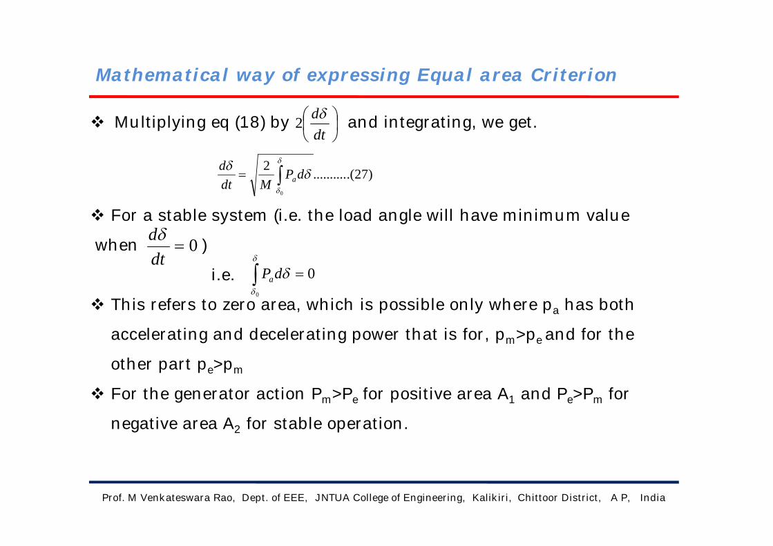
Mathematical way of expressing Equal area Criterion
Multiplying eq (18) by and integrating, we get.
For a stable system (i.e. the load angle will have minimum value
when )
i.e.
This refers to zero area, which is possible only where pa has both
accelerating and decelerating power that is for, pm>pe and for the
other part pe>pm
For the generator action Pm>Pe for positive area A1 and Pe>Pm for
negative area A2 for stable operation.
Prof. M Venkateswara Rao, Dept. of EEE, JNTUA College of Engineering, Kalikiri, Chittoor District, A P, India
dtd2
)27.(..........2
0
dP
Mdtd
a
0dtd
0
0dPa

Sudden change in Mechanical Input
Let the mechanical input to the generator rotor
be suddenly increased to Pm1.
Since Pm1>Pe the generator will have
Pa=Pm1-Pe
In this new steady state Pm1 = Pe1
.ˆ. Pm1 = Pe1 = Pmax sinδ1
The areas A1 and A2 can be evaluated as
Prof. M Venkateswara Rao, Dept. of EEE, JNTUA College of Engineering, Kalikiri, Chittoor District, A P, India
1
0
)( 11
dPPA em
dPPA me 1
2
)( 12
………….(28)
Sudden change in Mechanical Input (Contd…)
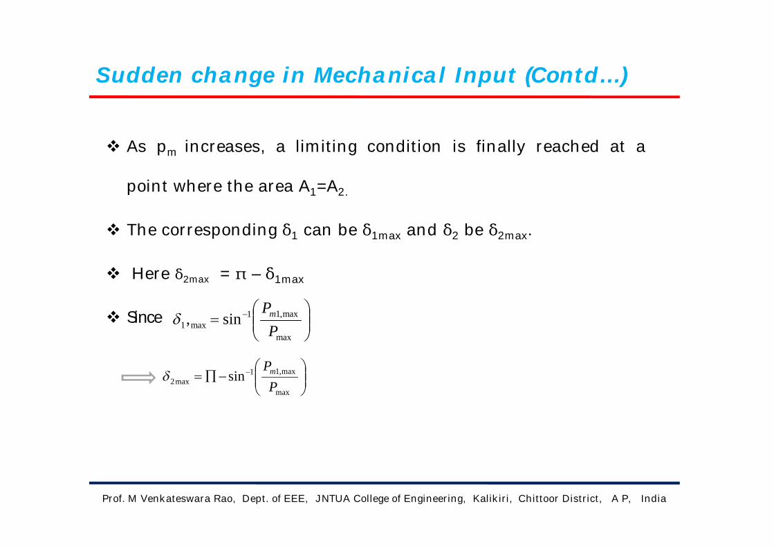
As pm increases, a limiting condition is finally reached at a
point where the area A1=A2.
The corresponding δ1 can be δ1max and δ2 be δ2max.
Here δ2max = π – δ1max
Since
Prof. M Venkateswara Rao, Dept. of EEE, JNTUA College of Engineering, Kalikiri, Chittoor District, A P, India
max
max,11max2 sin
PPm
max
max,11max1 sin,
PPm

Critical clearing angle & Critical clearing time
Critical clearing angle (δcc): It is the maximum allowable
change in the power angle δ, before clearing the fault, without
loss of synchronism.
Critical clearing time(tcc): It can be defined as the maximum
time delay that can be allowed to clear the fault without loss of
synchronism.
If the actual clearing angle is greater than the Critical clearing
angle, the system is unstable, otherwise it is stable.
Prof. M Venkateswara Rao, Dept. of EEE, JNTUA College of Engineering, Kalikiri, Chittoor District, A P, India
)29....(..........)(coscos 0maxmax
max1
PPm
cc
)30.......(..........)(2 0
m
cccc fP
Ht
20 2
tMPa

Sudden Loss of one of the parallel line
When both of the lines are operating the power transfer
is given by
When one of the lines is switched out the transfer reactance
increases and the power transfer is given by
The maximum value which can attain without
loss of system stability is δm and equals to
(π-δ1) radians.
Prof. M Venkateswara Rao, Dept. of EEE, JNTUA College of Engineering, Kalikiri, Chittoor District, A P, India
)31.........(sinsin max
21
211
1
I
d
e P
XXXX
X
EVP
)32....(..........sinsin max11
2 IId
e PXX
EVP
III PP maxmax

Fault and Subsequent circuit isolation
When fault develops at any point F on line2 it is subsequently
cleared by cleared by opening the CBS at both the ends of
faulted line.
3 power angle curves are involved,
• first for the pre fault system,
• second for the system during fault and
• third for the system after the fault line
If actual clearing δc < δcc system is stable,
If δc > δcc the system is unstable.
When δc = δcc the maximum angle up to which rotor swings is
δmax
Prof. M Venkateswara Rao, Dept. of EEE, JNTUA College of Engineering, Kalikiri, Chittoor District, A P, India
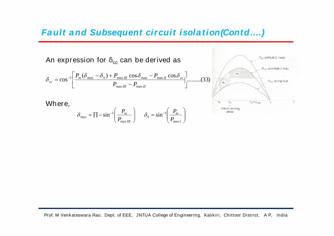
Fault and Subsequent circuit isolation(Contd….)
An expression for δcc can be derived as
Where,
Prof. M Venkateswara Rao, Dept. of EEE, JNTUA College of Engineering, Kalikiri, Chittoor District, A P, India
)33.........(coscos)(
cosmaxmax
maxmaxmax0max1
IIIII
ccIIIIImcc PP
PPP
I
m
PPmax
10 sin
III
m
PP
max
1max sin
Fault, Circuit isolation and reclosing
The transmission lines are provided with automatic quick reclosing
circuit breakers, because most of the faults are transient in nature
When fault occurs, operation shifts to curve for faulted condition.
When the load angle is δc, the faulted line is isolated and the
operation shifts to the post fault curve.
When the load angle is δ0 the circuit breaker reclose and operation
shifts to pre-fault curve.
For stable operation the accelerating area A1 = decelerating area A2.
The maximum angle to which rotor swings is δ2 and is less than δm
(i.e the maximum permissible rotor swing if stability is to be
maintained).
Prof. M Venkateswara Rao, Dept. of EEE, JNTUA College of Engineering, Kalikiri, Chittoor District, A P, India

Solution of swing equation by point by point method
Point by point (or step by step) method is the most feasible and
widely used way of solving the swing equations.
The main assumption for solving the swing equation by point by
point method is "the accelerating power is constant during time
interval" .
Integrating swing equation twice, w.r.t. time’t’,
After 1st integration,
After 2 nd integration,
Dividing the total time 't' into 'n' equal intervals.
Prof. M Venkateswara Rao, Dept. of EEE, JNTUA College of Engineering, Kalikiri, Chittoor District, A P, India
)34.......(0 MP
dtd a
)35........(200 MP
t a
)36.........(11
nnn PaM
t )37(..........2
)(. 1
2
11
nnnn PaMtt

Solution of swing equation by point by point method(Contd….)
The increments of speed and angular displacement during the nth interval
Prof. M Venkateswara Rao, Dept. of EEE, JNTUA College of Engineering, Kalikiri, Chittoor District, A P, India
)38.(..........11
nnnn PaM
t
)39..().........(2
)(21
2
1
nnnn PaPaMt

Methods of improving stability
By increasing inertia constant(M)
Increasing system voltage
Reduction of transfer reactance
• Use of double circuit lines
• Use of Bundle conductors
• Series compensation of the lines
Fast switching
Turbine fast valving ( or) By-pass valving
Single –pole switching
Load shedding
HVDC links
Breaking resistors
Prof. M Venkateswara Rao, Dept. of EEE, JNTUA College of Engineering, Kalikiri, Chittoor District, A P, India

Methods of improving stability (Contd…..)
Short circuit current limiters
Full load rejection technique
Prof. M Venkateswara Rao, Dept. of EEE, JNTUA College of Engineering, Kalikiri, Chittoor District, A P, India

Previous years GATE Questions
Q. No.1) Steady state stability of a power system is the ability of
the system to (GATE- 99)
A. Maintain Voltage at the rated level.
B. Maintain frequency exactly at 50Hz.
C. Maintain spinning reverse margin at all times.
D. Maintain Synchronism between machines and on external tie
lines.
Sol) A
Prof. M Venkateswara Rao, Dept. of EEE, JNTUA College of Engineering, Kalikiri, Chittoor District, A P, India

Previous years GATE Questions
Q. No.2) The transient stability of the power system can be
effectively improved by (GATE-93)
A) Excitation control
B) Phase shifting transformer
C) Single pole switching of circuit breakers
D) Increasing the turbine valve opening
Sol. C
Prof. M Venkateswara Rao, Dept. of EEE, JNTUA College of Engineering, Kalikiri, Chittoor District, A P, India

Previous years GATE Questions
Q. No.3) The angle δ in the swing equation of a synchronous
generator is (GATE-13)
A) Angle between stator voltage and current.
B) Angular displacement of stator with respect to rotor.
C) The angular displacement mmf with respect to a
synchronously rotating axis.
D) Angular displacement of an axis field to the rotor with respect
to a synchronously rotating axis.
Sol. D
Prof. M Venkateswara Rao, Dept. of EEE, JNTUA College of Engineering, Kalikiri, Chittoor District, A P, India

Previous years GATE Questions
Prof. M Venkateswara Rao, Dept. of EEE, JNTUA College of Engineering, Kalikiri, Chittoor District, A P, India

Previous years GATE Questions
Prof. M Venkateswara Rao, Dept. of EEE, JNTUA College of Engineering, Kalikiri, Chittoor District, A P, India
2/max
XVE
P

Previous years GATE Questions
Prof. M Venkateswara Rao, Dept. of EEE, JNTUA College of Engineering, Kalikiri, Chittoor District, A P, India

Previous years GATE Questions
Prof. M Venkateswara Rao, Dept. of EEE, JNTUA College of Engineering, Kalikiri, Chittoor District, A P, India
Previous years GATE Questions
Prof. M Venkateswara Rao, Dept. of EEE, JNTUA College of Engineering, Kalikiri, Chittoor District, A P, India
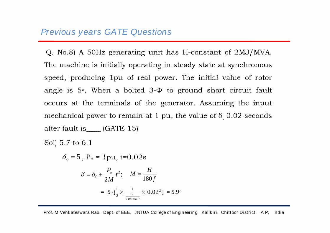
;2
20 t
MPa
fHM
180
50

Previous years GATE Questions
Q. No.9) A lossless single machine infinite bus power system is
shown in the fig. The synchronous generator transfers 1.0pu of
power to infinite bus. The critical clearing time of circuit braker is
0.28 s. If another identical synchronous generator is connected in
parallel to the existing generator and each generator is scheduled to
supply 0.5pu of power, the critical clearing time of the circuit
breaker will be (GATE-09)
Sol.
Pe= 0 during fault (Electrical power delivered )
Prof. M Venkateswara Rao, Dept. of EEE, JNTUA College of Engineering, Kalikiri, Chittoor District, A P, India
PadtdM up 2
2
).(
;/2
2
MPadtd
;
22 At
MPa

Previous years GATE Questions
Prof. M Venkateswara Rao, Dept. of EEE, JNTUA College of Engineering, Kalikiri, Chittoor District, A P, India
=ߜ oߜ
AMPa )0(
20
m
cccc fP
Ht
)(2 0

Previous years GATE Questions
Prof. M Venkateswara Rao, Dept. of EEE, JNTUA College of Engineering, Kalikiri, Chittoor District, A P, India

Previous years GATE Questions
Q. No.10) The figure shows single line diagram of power system
with a double circuit transmission line. The expression for
electrical power is 1.5 sinߜ , where ߜ is the rotor angle. The
system is operating at the stable equilibrium point with
mechanical power 1 pu. If one of the transmission line circuits is
removed, the maximum value of ,ߜ as the rotor swings is 1.221
radian. If the expression for electrical power with one
transmission line circuit removed is Pmaxsinߜ, the value of Pmax in
pu is ___(GATE-17)
Sol) 1.22
Continued in the next page.
Prof. M Venkateswara Rao, Dept. of EEE, JNTUA College of Engineering, Kalikiri, Chittoor District, A P, India

Previous years GATE Questions
Prof. M Venkateswara Rao, Dept. of EEE, JNTUA College of Engineering, Kalikiri, Chittoor District, A P, India
0)()(2
1
1
0
22
dPPdPP eses
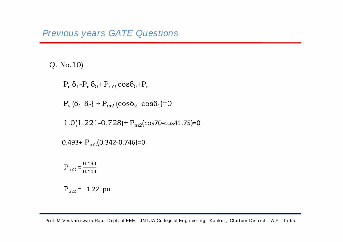
Previous years GATE Questions
Prof. M Venkateswara Rao, Dept. of EEE, JNTUA College of Engineering, Kalikiri, Chittoor District, A P, India
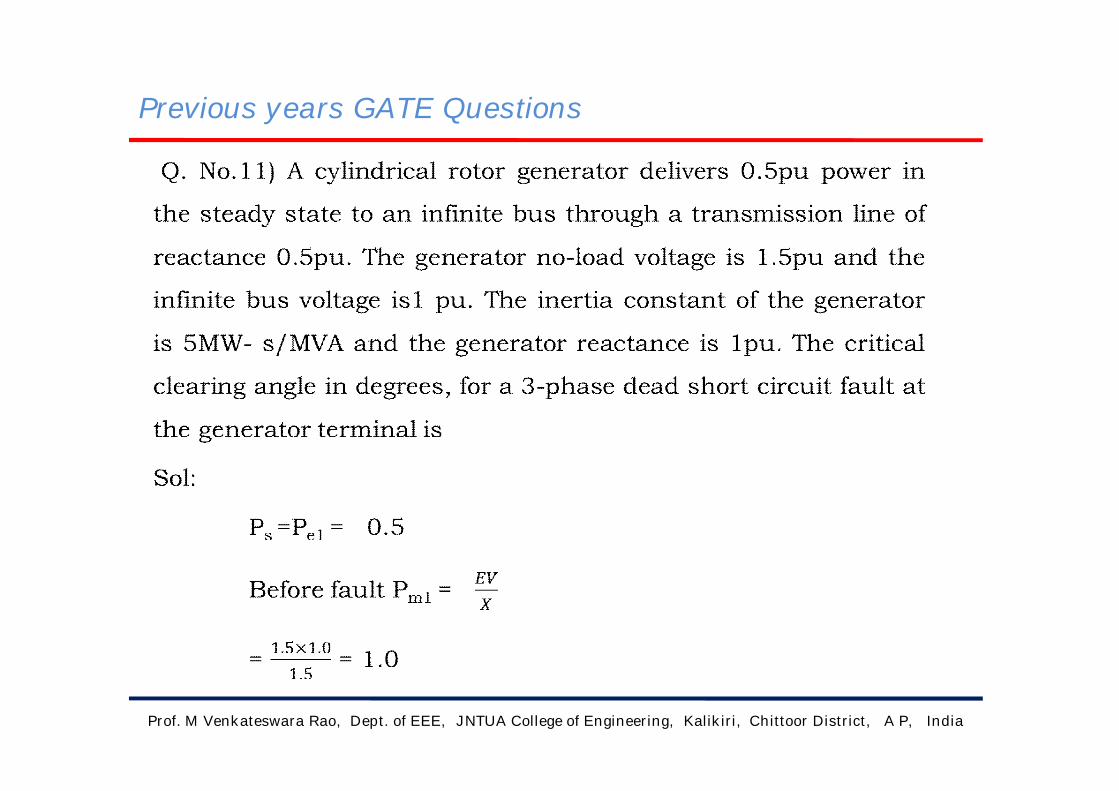
Previous years GATE Questions
Prof. M Venkateswara Rao, Dept. of EEE, JNTUA College of Engineering, Kalikiri, Chittoor District, A P, India

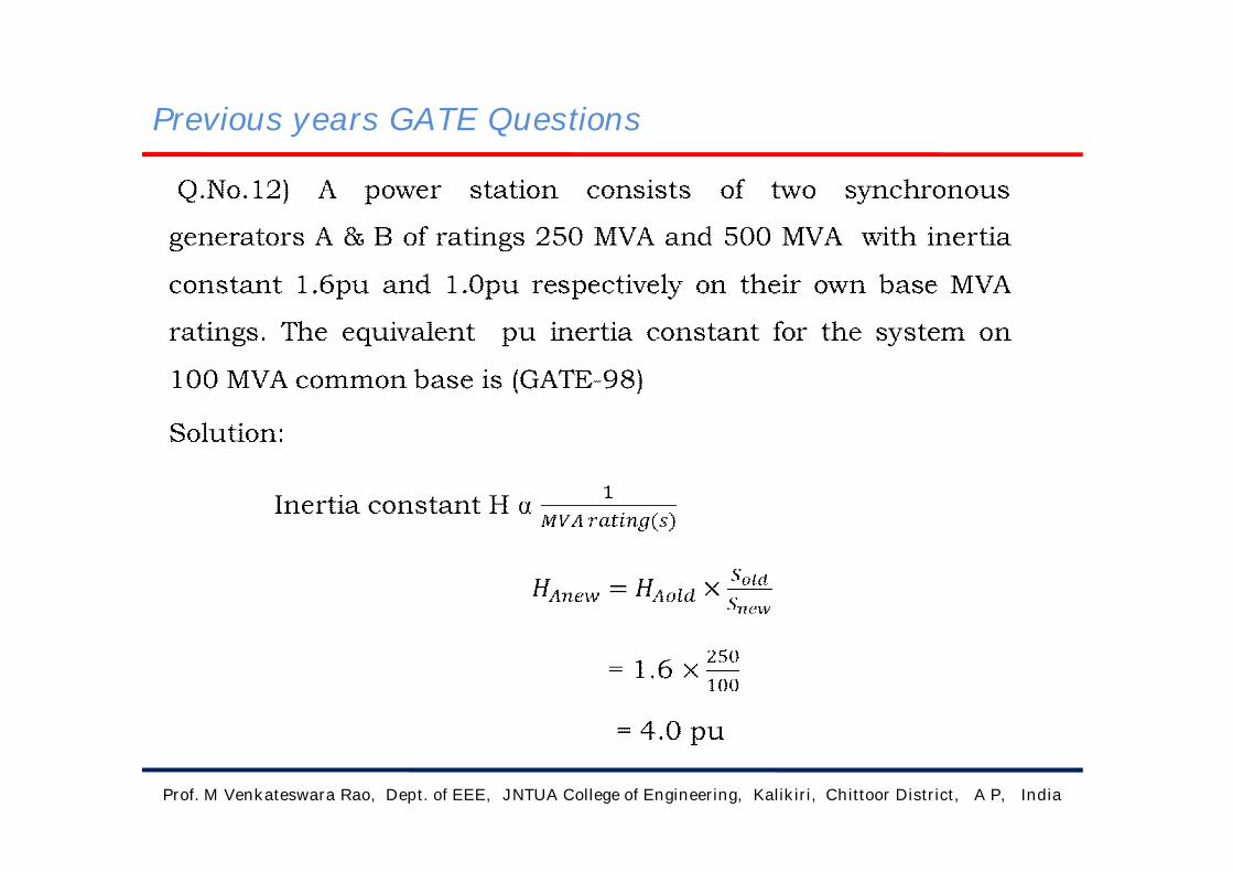
Previous years GATE Questions
Prof. M Venkateswara Rao, Dept. of EEE, JNTUA College of Engineering, Kalikiri, Chittoor District, A P, India

Previous years GATE Questions
Prof. M Venkateswara Rao, Dept. of EEE, JNTUA College of Engineering, Kalikiri, Chittoor District, A P, India
Previous years GATE Questions
Prof. M Venkateswara Rao, Dept. of EEE, JNTUA College of Engineering, Kalikiri, Chittoor District, A P, India

Previous years GATE Questions
Prof. M Venkateswara Rao, Dept. of EEE, JNTUA College of Engineering, Kalikiri, Chittoor District, A P, India

Previous years GATE Questions
Prof. M Venkateswara Rao, Dept. of EEE, JNTUA College of Engineering, Kalikiri, Chittoor District, A P, India
Block diagram of two-area load frequency control
b1PD1 (S)
-a12
PD2 (S) b2
+
+
+
+
+
+
+
+
+
+
+
+
+
+
+
PC1(S) PG1(S) F1(S) F2(S) PG2(S) PC1(S)
Ptie, 1(S) Ptie, 2(S)
Copyright © 2022 FDOKUMEN