Performance comparison of SVC and SSSC with POD controller for Power System Stability
10
IOSR Journal of Electrical and Electronics Engineering (IOSR-JEEE) e-ISSN: 2278-1676,p-ISSN: 2320-3331, Volume 6, Issue 2 (May. - Jun. 2013), PP 28-37 www.iosrjournals.org www.iosrjournals.org 28 | Page Performance comparison of SVC and SSSC with POD controller for Power System Stability K. Kalyan Kumar 1 , V. Shararth Babu 2 , M. Hari Babu 3 , R. Bhaskar 4 1, 2, 3, 4 (EEE, Vardhaman College of Engineering (Autonomous), India) Abstract : Steady state and transient problems in a power system have undesirable consequences on the system. It can limit the amount of power that can be transmitted in the system and consequently leads to voltage instability and at times it may also result into total voltage collapse.The main objective of this paper is a comparative investigate in enhancement of volatge stability via static synchronous series compensator (SSSC) and static var compensator (SVC) externally controlled by a POD controller.The new designed P.O.D controller is very efficient for voltage stability under transient conditions. This paper discusses and demonstrates the comparision between the SVC with P.O.D controller and SSSC with P.O.D controller,applied to power system for effectively regulating system voltage for different types of faulted condition. One of the major reasons for installing a SVC is to improve dynamic voltage control and thus increase system load ability during transient condition. This work is presented to present the transmission line voltage stability & machine oscillation damping stability by using SVC & SSSC with POD controller & compared their performance to enhance the stability of a power system. Simulation results shows that SVC with POD controller is more effective to enhance the voltage stability and increase transmission capacity in a power system. Keywords– FACTS,Power system, POD Controller,SVC(Static VAR compensator), SSSC(static synchronous series compensator),Voltage Stability. I. INTRODUCTION Today’s changing electric power systems create a growing need for flexibility, reliability, fast response and accuracy in the fields of electric power generation, transmission, distribution and consumption. Flexible Alternating Current Transmission Systems (FACTS) are new devices emanating from recent innovative technologies that are capable of altering voltage, phase angle and/or impedance at particular points in power systems .Their fast response offers a high potential for power system stability enhancement apart from steady- state flow control. Since then the large effort was put in research and development of FACTS controllers. Static Synchronous Compensator (STATCOM), Static Synchronous Series Compensator (SSSC) and Unified Power Flow Controller (UPFC) etc., bus voltages, line impedances and phase angles in the power system can be regulated rapidly and flexibly. These FACTS controllers are based on voltage source converters. Thus, FACTS can facilitate the power flow control, enhance the power transfer capability, decrease the generation cost, and improve the security and stability of the power system. Among the FACTS controllers, Static Var Compensator (SVC) provides fast acting dynamic reactive compensation for voltage support during contingency events which would otherwise depress the voltage for a significant length of time.SVC also dampens power swings and reduces system losses by optimized reactive power control. In previous works the effective methods of control have been implemented to control of SVC in order to damp power swings. A Static Synchronous Series Compensator (SSSC) is another member of FACTS family which is connected in series with a power system. It consists of a solid state voltage source converter which generates a controllable alternating current voltage at fundamental frequency. When the injected voltage is kept in quadrature with the line current, it can emulate as inductive or capacitive reactance so as to influence the power flow through the transmission line. While the primary purpose of a SSSC is to control power flow in steady state, it can also improve transient stability of a power system. SSSC is proposed as the most adequate for the present application well discussed [1]. The DC inner bus of the SSSC allows incorporating a substantial amount of energy storage in order to enlarge the degrees of freedom of the SSSC device and also to exchange active and reactive power with utility grid. A Power Oscillation Damping (POD) controller with a conventional structure is installed on the SSSC to improve the system dynamic behavior. The damping of power oscillations by static synchronous series compensator (SSSC) based damping controllers. The advantage of this approach is that it can handle the nonlinearities, at the same time it is faster than other conventional controllers and it improve the reactive power of the system. Simulation studies are carried out in Matlab/Simulink environment to evaluate the effectiveness of the proposed Static synchronous series compensator (SSSC) based on the POD controller. The proposed SSSC based damping controllers improve the damping performance of the system in the event of a major disturbance.
-
Upload
independent -
Category
Documents
-
view
0 -
download
0
Transcript of Performance comparison of SVC and SSSC with POD controller for Power System Stability

IOSR Journal of Electrical and Electronics Engineering (IOSR-JEEE)
e-ISSN: 2278-1676,p-ISSN: 2320-3331, Volume 6, Issue 2 (May. - Jun. 2013), PP 28-37 www.iosrjournals.org
www.iosrjournals.org 28 | Page
Performance comparison of SVC and SSSC with POD controller
for Power System Stability
K. Kalyan Kumar1, V. Shararth Babu
2, M. Hari Babu
3, R. Bhaskar
4
1, 2, 3, 4(EEE, Vardhaman College of Engineering (Autonomous), India)
Abstract : Steady state and transient problems in a power system have undesirable consequences on the
system. It can limit the amount of power that can be transmitted in the system and consequently leads to voltage
instability and at times it may also result into total voltage collapse.The main objective of this paper is a
comparative investigate in enhancement of volatge stability via static synchronous series compensator (SSSC)
and static var compensator (SVC) externally controlled by a POD controller.The new designed P.O.D
controller is very efficient for voltage stability under transient conditions. This paper discusses and
demonstrates the comparision between the SVC with P.O.D controller and SSSC with P.O.D controller,applied
to power system for effectively regulating system voltage for different types of faulted condition. One of the
major reasons for installing a SVC is to improve dynamic voltage control and thus increase system load ability
during transient condition. This work is presented to present the transmission line voltage stability & machine
oscillation damping stability by using SVC & SSSC with POD controller & compared their performance to
enhance the stability of a power system. Simulation results shows that SVC with POD controller is more effective to enhance the voltage stability and increase transmission capacity in a power system. Keywords– FACTS,Power system, POD Controller,SVC(Static VAR compensator), SSSC(static synchronous
series compensator),Voltage Stability.
I. INTRODUCTION Today’s changing electric power systems create a growing need for flexibility, reliability, fast response
and accuracy in the fields of electric power generation, transmission, distribution and consumption. Flexible Alternating Current Transmission Systems (FACTS) are new devices emanating from recent innovative
technologies that are capable of altering voltage, phase angle and/or impedance at particular points in power
systems .Their fast response offers a high potential for power system stability enhancement apart from steady-
state flow control. Since then the large effort was put in research and development of FACTS controllers. Static
Synchronous Compensator (STATCOM), Static Synchronous Series Compensator (SSSC) and Unified Power
Flow Controller (UPFC) etc., bus voltages, line impedances and phase angles in the power system can be
regulated rapidly and flexibly. These FACTS controllers are based on voltage source converters. Thus, FACTS
can facilitate the power flow control, enhance the power transfer capability, decrease the generation cost, and
improve the security and stability of the power system. Among the FACTS controllers, Static Var Compensator
(SVC) provides fast acting dynamic reactive compensation for voltage support during contingency events which
would otherwise depress the voltage for a significant length of time.SVC also dampens power swings and
reduces system losses by optimized reactive power control. In previous works the effective methods of control have been implemented to control of SVC in order to damp power swings. A Static Synchronous Series Compensator (SSSC) is another member of FACTS family which is
connected in series with a power system. It consists of a solid state voltage source converter which generates a
controllable alternating current voltage at fundamental frequency. When the injected voltage is kept in
quadrature with the line current, it can emulate as inductive or capacitive reactance so as to influence the power
flow through the transmission line. While the primary purpose of a SSSC is to control power flow in steady
state, it can also improve transient stability of a power system. SSSC is proposed as the most adequate for the
present application well discussed [1]. The DC inner bus of the SSSC allows incorporating a substantial amount
of energy storage in order to enlarge the degrees of freedom of the SSSC device and also to exchange active and
reactive power with utility grid.
A Power Oscillation Damping (POD) controller with a conventional structure is installed on the SSSC to improve the system dynamic behavior. The damping of power oscillations by static synchronous series
compensator (SSSC) based damping controllers. The advantage of this approach is that it can handle the
nonlinearities, at the same time it is faster than other conventional controllers and it improve the reactive power
of the system. Simulation studies are carried out in Matlab/Simulink environment to evaluate the effectiveness
of the proposed Static synchronous series compensator (SSSC) based on the POD controller. The proposed
SSSC based damping controllers improve the damping performance of the system in the event of a major
disturbance.

Performance comparison of SVC and SSSC with POD controller for Power System Stability
www.iosrjournals.org 29 | Page
MATLAB/SIMULINK used in this study to conduct simulations on voltage regulation at the point of
connection of SVC & SSSC with POD controller to the system. However, the aim of this paper is to compare
the performances of SVC & SSSC with POD controller to enhance voltage stability at the event of occurrence of
fault in the system. Among the available FACTS devices, the Unified Power Flow Controller (UPFC) is the
most versatile one that can be used to improve steady state stability, dynamic stability and transient stability [4].
The UPFC can independently control many parameters since it is the combination of Static Synchronous
Compensator (STATCOM) and SSSC. These devices offer an alternative mean to mitigate power system oscillations. It has been reported in many papers that UPFC can improve stability of single machine infinite bus
(SMIB) system and multimachine system [5]-[6]. The inter-area power system has special characteristic of
stability behaviour [19].
II. Concept Of Svc An SVC is a controlled shunt susceptance (B) which inject reactive power (Qnet) into thereby increasing
the bus voltage back to its net desired voltage level. If bus voltage increases, the SVC will inject less (or TCR
will absorb more) reactive power, and the result will be to achieve the desired bus vol-tage. Fig.1, represents
SVC based control system with AVR, & POD controller.
SVC (AVR) controller always monitor the bus vol-tage(Vsvc) & current (Isvc), it compare the actual bus
voltage with Vref & taking error voltage, Verror = Vref – Va – (Isvc*Xsl) & integrate it in limit (-Qcap to +Qind), the net
susceptance has been produced which control the pulse generator & Thus TCR & TSC are controlled & voltage
becomes stable to-wards it’s Vref shown in Fig.1 [7-8].
Fig. 1 SVC based Control System Fig. 2 Steady state(V-I) characteristics of a SVC
2.1 SVC V-I Characteristic
The SVC can be operated in two different modes:
a). In voltage regulation mode (the voltage is regulated with-in limits as explained below).
b). In VAR control mode (the SVC susceptance is kept con-stant). From V-I curve of SVC, From Fig.3,
V=Vref+Xs.I,: In regulation range(-Bcmax<B<Bcmax) V=I/Bcmax, , : SVC is fully Capacitive(B=Bcmax) V=1/Blmax, :
SVC is fully inductive(B=Blmax)
2.2 SVC Structure
Electrical loads both generate and absorb reactive power. Since the transmitted load varies
considerably from one hour to another, the reactive power balance in a grid varies as well. The result can be unacceptable voltage amplitude variations or even a voltage depression, at the extreme a voltage collapse. A
rapidly operating Static Var Compensator (SVC) can continuously provide the reactive power required to
control dynamic voltage oscillations under various system conditions and thereby improve the power system
transmission and distribution stability. Installing an SVC at one or more suitable points in the network can
increase transfer capability and reduce losses while maintaining a smooth voltage profile under different
network conditions. In addition an SVC can mitigate active power oscillations through voltage amplitude
modulation. SVC installations consist of a number of building blocks. The most important is the Thyristor valve,
i.e. stack assemblies of series connected anti-parallel Thyristors to provide controllability.
Air core reactors and high voltage AC capacitors are the reactive power elements used together with
the Thyristor valves. The step up connection of this equipment to the transmission voltage is achieved through a
power transformer. The Thyristor valves together with auxiliary systems are located indoors in an SVC building,

Performance comparison of SVC and SSSC with POD controller for Power System Stability
www.iosrjournals.org 30 | Page
while the air core reactors and capacitors, together with the power transformer are located outdoors. In principle
the SVC consists of Thyristor Switched Capacitors (TSC) and Thyristor Switched or Controlled Reactors (TSR /
TCR). The coordinated control of a combination of these branches varies the reactive power as shown in Fig. 3.
Fig. 3 SVC Building blocks and voltage / Current characteristics
The first commercial SVC was installed in 1972 for an electric arc furnace. On transmission level the
first SVC was used in 1979. Since then it is widely used and the most accepted FACTS-device
2.3 Network modeling with SVC
This example described in this section illustrates modeling of a simple transmission system containing
two hydraulic power plants. Static VAR compensator (SVC) has been used to improve voltage stability and
power system oscillations damping. A single line diagram represents a simple 500 kV transmission system is
shown in Fig. 4.
Fig.4 Single line diagram of a 2-machine power system
III. Static Synchronous Series Compensator (SSSC) 3.1 Operating principle of SSSC
The SSSC is one of the most recent FACTS devices for power transmission series compensation. It can
be considered as a synchronous voltage source as it can inject an almost sinusoidal voltage of variable and
controllable amplitude and phase angle in series with a transmission line. The injected voltage is almost in quadrature with the line current. A small part of the injected voltage that is in phase with the line current
provides the losses in the inverter. Most of the injected voltage, which is in quadrature with the line current,
provides the effect of inserting an inductive or capacitive reactance in series with the transmission line. The
variable reactance influences the electric power flow in the transmission line. The basic configuration of a SSSC
is shown in Fig.5
.
Fig.5 Simplified diagram of a SSSC Fig.6 SSSC Phasor diagram
Theoretically, SSSC operation in each of the four quadrants is possible, Theoretically, SSSC operation
in each of the four quadrants is possible, but there are some limitations to the injected SSSC voltage due to
operating constraints of practical power system. In capacitive mode, the injected SSSC voltage is made to lag
the transmission line current by90°; in this case, the SSSC operation is similar to the operation of a series
capacitor with variable capacitance kXc, i.e., Vpq= − jKXcIline, where k is a variable.
3.2 Rating of the SSSC
The SSSC can provide capacitive or inductive compensating voltage independent of the line current.
The VA rating of the SSSC (solid-state inverter and coupling transformer) is simplythe product of the maximum

Performance comparison of SVC and SSSC with POD controller for Power System Stability
www.iosrjournals.org 31 | Page
line current (at which compensation is still desired) and the maximum series compensating voltage: VA =
ImaxVmax. An SSSC of 1 p.u. VA rating covers a control range corresponding to 2 p.u. compensating VARs, that
is the control range is continuous from -1 p.u. (inductive) VARs to +1 p.u. (capacitive) VARs.
3.3 Internal Controls
From the standpoint of output voltage control, converters may be categorized as “directly” and
“indirectly” controlled. For directly controlled converters both the angular position and the magnitude of the output voltage are controllable by appropriate valve (on and off) gating. For indirectly controlled converters
only the angular position of the output voltage is controllable by valve gating; the magnitude remains
proportional to the dc terminal voltage. The control method of maintaining a quadrature relationship between
the instantaneous converter voltage and line current vectors, to provide reactive series compensation and handle
SSR, can be implemented with an indirectly controlled converter. The method of maintaining a single frequency
synchronous (i.e. fundamental) output independent of dc terminal voltage variation requires a directly controlled
converter. Although high power directly controlled converters are more difficult and costly to implement than
indirectly controlled converters (because their greater control flexibility is usually associated with some penalty
in terms of increased losses, greater circuit complexity, and/or increased harmonic content in the output),
nevertheless they can be realized to meet practical utility requirements.
The SSSC, in series with line is capable of injecting up to 10% of the nominal system voltage. The SSSC injected voltage reference is normally set by a POD (Power Oscillation Damping) controller whose output
is connected to the Vqref input of the SSSC. The POD controller consists of an active power measurement
system, a general gain, a low-pass filter, a washout high-pass filter, a lead compensator, and an output limiter.
The inputs to the POD controller are the bus voltage and the current flowing in Line.
IV. Test System Description 4.1. SSSC with POD Controller
The power grid consists of two power generation substations and one major load center at bus B3. The
first power generation substation (M1) has a rating of 2100 MVA, representing 6 machines of 350 MVA and the other one (M2) has a rating of 1400 MVA, representing 4 machines of 350 MVA. The load center of
approximately 2200 MW is modeled using a dynamic load model where the active & reactive power absorbed
by the load is a function of the system voltage. The generation substation M1 is connected to this load by two
transmission lines L1 and L2. L1 is 280-km long and L2 is split in two segments of 150 km in order to simulate
a three-phase fault (using a fault breaker) at the midpoint of the line. The generation substation M2 is also
connected to the load by a 50-km line (L3). When the SSSC is bypass, the power flow towards this major load is
as follows: 664 MW flow on L1 (measured at bus B2), 563 MW flow on L2 (measured at B4) and 990 MW
flow on L3 (measured at B3).
Fig. 7 Simulation Diagram of the SSSC

Performance comparison of SVC and SSSC with POD controller for Power System Stability
www.iosrjournals.org 32 | Page
The SSSC, located at bus B1, is in series with line L1. It has a rating of 100MVA and is capable of
injecting up to 10% of the nominal system voltage. This SSSC is a phasor model of a typical three-level PWM
SSSC. The model represents a SSSC having a DC link nominal voltage of 40 kV with an equivalent capacitance
of 375 uF. On the AC side, its total equivalent impedance is 0.16 pu on 100 MVA. This impedance represents
the transformer leakage reactance and the phase reactor of the IGBT bridge of an actual PWM SSSC. The SSSC
injected voltage reference is normally set by a POD (Power Oscillation Damping) controller whose output is
connected to the Vqref input of the SSSC. The POD controller consists of an active power measurement system, a general gain, a low-pass filter, a washout high-pass filter, a lead compensator, and an output limiter. The
inputs to the POD controller are the bus voltage at B2 and the current flowing in L1.
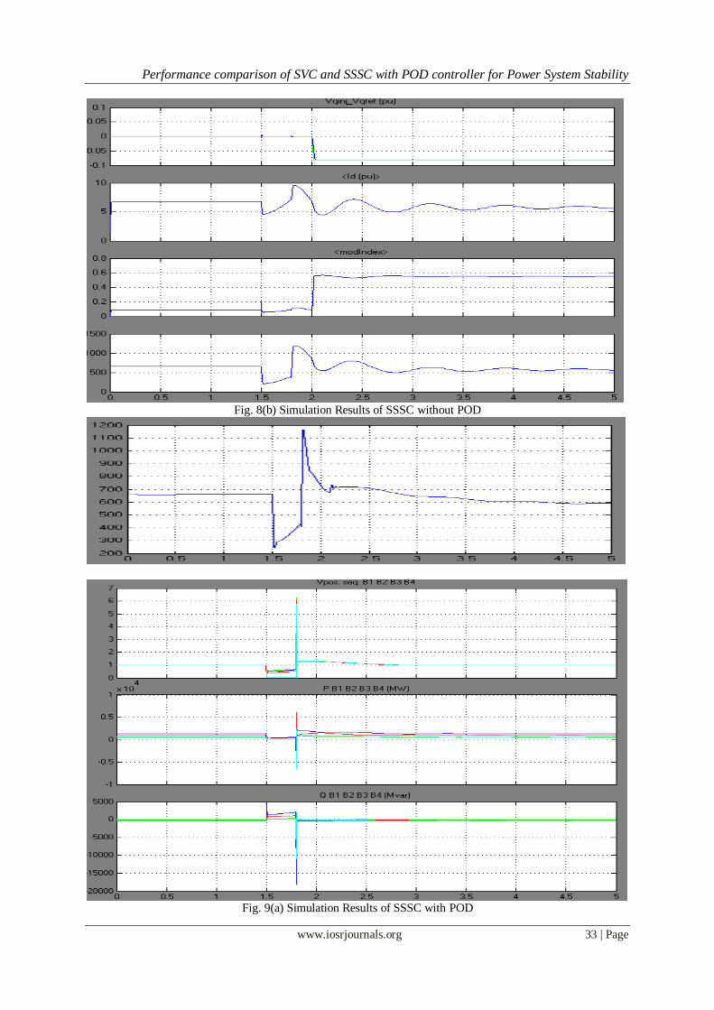
Fig. 8(b) Simulation Results of SSSC without POD
Performance comparison of SVC and SSSC with POD controller for Power System Stability
www.iosrjournals.org 33 | Page
Fig. 8(b) Simulation Results of SSSC without POD
Fig. 9(a) Simulation Results of SSSC with POD

Performance comparison of SVC and SSSC with POD controller for Power System Stability
www.iosrjournals.org 34 | Page
Fig. 9(b) Simulation Results of SSSC with POD
4.2 SVC Controller
Fig. 10 Simulation Diagram of SVC Controller
A static var compensator (SVC) is used to regulate voltage on a 500 kV, 3000 MVA sytem. When
system voltage is low the SVC generates reactive power (SVC capacitive). When system voltage is high it
absorbs reactive power (SVC inductive). The SVC is rated +200 Mvar capacitive and 100 Mvar inductive. The
Static Var Compensator block is a a phasor model representing the SVC static and dynamic characteristics at the
system fundamental frequency.
To see the SVC control parameters, open the SVC dialog box and select "Display Control parameters".
The SVC is set in voltage regulation mode with a reference voltage Vref=1.0 pu. The voltage droop is 0.03 pu/
200MVA, so that the voltage varies from 0.97 pu to 1.015 pu when the SVC current goes from fully capacitive to fully inductive. Double click now on the blue block to display the SVC V-I characteristic.
Performance comparison of SVC and SSSC with POD controller for Power System Stability
www.iosrjournals.org 35 | Page
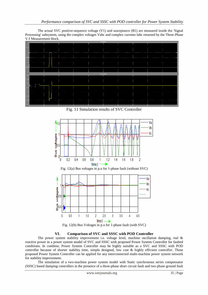
The actual SVC positive-sequence voltage (V1) and susceptance (B1) are measured inside the 'Signal
Processing' subsystem, using the complex voltages Vabc and complex currents Iabc returned by the Three-Phase
V-I Measurement block.
Fig. 11 Simulation results of SVC Controller
Fig. 12(a) Bus voltages in p.u for 1-phase fault (without SVC)
Fig. 12(b) Bus Voltages in p.u for 1-phase fault (with SVC)
VI. Comparison of SVC and SSSC with POD Controller The power system stability improvement i.e. voltage level, machine oscillation damping, real &
reactive power in a power system model of SVC and SSSC with proposed Power System Controller for faulted
conditions. In combine, Power System Controller may be highly suitable as a SVC and SSSC with POD controller because of shorter stability time, simple designed, low cost & highly efficient controller. These
proposed Power System Controller can be applied for any interconnected multi-machine power system network
for stability improvement. The simulation of a two-machine power system model with Static synchronous series compensator
(SSSC) based damping controllers in the presence of a three-phase short circuit fault and two phase ground fault

Performance comparison of SVC and SSSC with POD controller for Power System Stability
www.iosrjournals.org 36 | Page
are considered. The results show that the power system oscillations are damped out very quickly with the help of
SSSC based damping controllers in few seconds. As the modulation ratio lies between zero and one, the dc
voltage should not be lower than the maximum of the requested SSSC output phase voltage in order to obtain
proper control. On the other hand, if the dc side voltage is too high, the rating of both the GTO valves and dc
capacitor has to be increased, which means higher installation costs. Not only that, a higher dc side voltage
means a lower amplitude modulation ratio and the lower modulation ratio results in higher harmonic distortion.
Phase control allows the dc voltage to change according to the power system conditions, which is clearly advantageous, but it requires a more complicated controller and special and costly series transformers. The
results show that the use of SSSC is having improved dynamic response and at the same time faster than other
conventional controllers.
The most suitable location for SVC and SSSC with POD controller to control power flow and to
improve voltage Profile. The improvement of voltage stability by SSSC and SVC would be better than that of
either by STATCOM or TCSC. In case of without SVC and SSSC with POD, generation of reactive power can
be increased, total real power losses are more, voltage stability index is high. In case of with SVC and SSSC
with POD, generation of reactive power generation can be reduced, total real power losses are less, voltage
stability index is low.
Table 1 Comparison of SVC and SSSC Issue SVC SSSC
V/I characteristic
Good overvoltage performance Impedance Good under voltage performance Voltage source
Control range freely adjustable to any range by TCR/TSR /TSC branches
Symmetrical
Modularity TCR/TSR/TSC branches used in SVC and
TCSC/TPSC Redundancy Degraded mode operation
Same converter usable for various applications
UPFC, SSSC configurations are used in the CSC
Response time 2 to 3 cycle 3 to 4 cycle
Transient behavior
Available before, during and after critical system conditions
Self protecting at critical system faults
Space
requirements
100 % 60 to 70 %
Availability > 99 % 90 o 92 %
VII. CONCLUSION This paper explains, the FACTS controllers that are used to mitigate the power quality problems. The
standard FACTS controller for a particular type of problem is also given. The simulation results give the clear
observation of how the FACTS devices improve the power quality. The simulation work is done on Static Var
Compensator (SVC)and Static Synchronous Series Compensator(SSSC).SVC and SSSC are providing better
power quality under variation of source voltage and when the system is suddenly loaded. The thesis includes the
simulation results of the SVC and SSSC only. The future work given as the simulation results of the systems for
various power quality problems with all remaining FACTS devices. Then it can be very easy to find an exact
FACTS device for a particular type of power quality problem.
Installations of SSSC and SVC controllers at all suitable locations will naturally improve the voltage
stability of a power system. But, keeping in mind, the cost of the controllers and the optimization task, the number of controllers and their sizes are minimized. Taking corrective actions to keep the system voltage
secured under all possible line outage contingency will not be economical or it may not be necessary. Therefore,
only the most critical line outage contingency is considered. The line outage is ranked according to the severity
and the severity is taken on the basis of increased reactive power generation and real power losses. Outage of
other lines has no much impact on the system and therefore they are not given importance
REFERENCES [1] Molina, M.G. and P. E. Mercado, “Modeling of a Static Synchronous Compensator withSuperconducting Magnetic Energy Storage
for Applications on Frequency Control”, Proc. VIII SEPOPE, Brasilia, Brazil, 2002, pp. 17-22.
[2] Molina, M.G. and P. E. Mercado, “New Energy Storage Devices for Applications on Frequency Control of the Power System using
FACTS Controllers,” Proc. X ERLAC, Iguazú, Argentina, 14.6, 2003, 1-6.
[3] Molina, M.G. and P. E. Mercado, “Evaluation of Energy Storage Systems for application in the Frequency Control”, Proc. 6th
COBEP, Florianópolis, Brazil, 2001, pp. 479-484.
[4] M. Noroozian, L. Angquist, M. Ghandhari, G. Andersson,1997, “Use of UPFC for Optimal Power Flow Control,” IEEE
Transactions on Power Delivery, 12(4), pp. 1629-1634.
[5] M. Ghandhari, G. Andersson, I.A. Hiskens, 2001, “Control Lyapunov Functions for Series Devices,” IEEE Transactions on Power
Delivery, 16(4), pp. 689-694.

Performance comparison of SVC and SSSC with POD controller for Power System Stability
www.iosrjournals.org 37 | Page
[6] P. Kumkratug, M.H. Haque, 2003, “Versatile Model of a Unified Power Flow Controller in Simple System,” IEE Proc. Gener.
Transm. & Distrib., 150(2), pp. 155-161
[7] Habibur, Dr. Fayzur, Harun, ’Online voltage level im-provement by using SVC & PSS’ “International Jour-nal of system &
simulation”.Vol.06,No.02(Dec,2012) Issue(Received for publication)
[8] " MATLAB Math Library User's Guide", by the Math Works. Inc
[9] Singh, R. Singh, D.K. Simulation of D-STATCOM for Voltage Fluctuation Page(s): 225 - 230 Advanced Computing &
Communication Technologies (ACCT), 2012 Second International Conference.
[10] Hingorani N. G., Gyugyi L., Understanding FACTS concepts and Technology of flexible AC transmission systems, New York.
IEEE Press, 2000.
[11] A. H. Norouzi and A. M. Sharaf, “Two control schemes to enhance the dynamic performance of the STATCOM and SSSC”, IEEE
Trans. Power Del., vol. 20, no. 1, pp.435–442, Jan. 2005.
[12] M. S. El-Moursi and A. M. Sharaf, “Novel Controllers for the 48-Pulse VSC STATCOM and SSSC for Voltage Regulation and
Reactive Power Compensation”, IEEE Transactions on Power Systems, vol.20,no.4,November 2005.
[13] N. Magaji and M.W. Mustafa, “Optimal Thyristor Control Series Capacitor Neuro-Controller for Damping Oscillations”, Journal of
Computer Science, Vol.5, No.12, 2009, pp. 983-990.
[14]. K.R. Padiyar, S. Krishna and NageshPrabhu, “On-line detection of loss of synchronism is large power systems”, Int. Conf. on
Power Systems, Katmandu, Nepal, November 2004.
[15] A.K.S.N. Polisetty, “Application of custom power devices for improving power quality”, M.E. Project Report, Indian Institute of
Science,July 2005.