
UNIT- V POWER SYSTEM STABILITY ... - SNS Courseware
27
POWER SYSTEM ANALYSIS / R. HARISH /AP/EEE UNIT- V POWER SYSTEM STABILITY Power System Stability The stability of an interconnected power system means is the ability of the power system is to return or regain to normal or stable operating condition after having been subjected to some form of disturbance. Power system stability is classified Rotor Angle Stability Rotor angle stability is the ability of interconnected synchronous machines of a power system to remain in synchronism.
-
Upload
khangminh22 -
Category
Documents
-
view
1 -
download
0
Transcript of UNIT- V POWER SYSTEM STABILITY ... - SNS Courseware

POWER SYSTEM ANALYSIS / R. HARISH /AP/EEE
UNIT- V
POWER SYSTEM STABILITY
Power System Stability The stability of an interconnected power system means is the ability of
the power system is to return or regain to normal or stable operating
condition after having been subjected to some form of disturbance.
Power system stability is classified
Rotor Angle Stability Rotor angle stability is the ability of interconnected synchronous
machines of a power system to remain in synchronism.

POWER SYSTEM ANALYSIS / R. HARISH /AP/EEE
Steady State Stability Steady state stability is defined as the ability of the power system to bring
it to a stable condition or remain in synchronism after a small
disturbance.
Steady state stability limit The steady sate stability limit is the maximum power that can be
transferred by a machine to receiving system without loss of synchronism
Transient stability Transient stability is defined as the ability of the power system to bring it
to a stable condition or remain in synchronism after a large disturbance.
Transient Stability Limit The transient stability limit is the maximum power that can be transferred
by a machine to a fault or a receiving system during a transient state
without loss of synchronism.
Transient stability limit is always less than steady state stability limit
Dynamic stability It is the ability of a power system to remain in synchronism after the
initial swing (transient stability period) until the system has settled down
to the new steady state equilibrium condition
Voltage stability It is the ability of a power system to maintain steady acceptable voltages
at all buses in the system under normal operating conditions and after
being subjected to a disturbance.
Causes of voltage instability
A system enters a state of voltage instability when a disturbance, increase
in load demand, or change in system condition causes a progressive and
uncontrollable drop in voltage
The main factor causing instability is the inability of the power system to
meet the demand for reactive power.
Power angle equation and draw the power angle curve
Where,
P – Real Power in watts
Vs – Sending end voltage; Vr- Receiving end voltage
XT - Total reactance between sending end receiving end
- Rotor angle.

POWER SYSTEM ANALYSIS / R. HARISH /AP/EEE
Swing equation for a SMIB (Single machine connected to an infinite bus
bar) system.
Where
H = inertia constant in MW/MVA
f = frequency in Hz
M = inertia constant in p.u
Swing curve The swing curve is the plot or graph between the power angle δ and time
t. From the nature of variations of δ the stability of a system for any
disturbance can be determined.

POWER SYSTEM ANALYSIS / R. HARISH /AP/EEE
3machine system having ratings G1, G2 and G3 and inertia constants M1,
M2 and M3.What is the inertia constants M and H of the equivalent
system.
Where
G1, G2, G3 – MVA rating of machines 1, 2, and 3
Gb = Base MVA or system MVA
Assumptions made in stability studies. Machines represents by classical model
The losses in the system are neglected (all resistance are neglected)
The voltage behind transient reactance is assumed to remain constant.
Controllers are not considered ( Shunt and series capacitor )
Effect of damper winding is neglected.
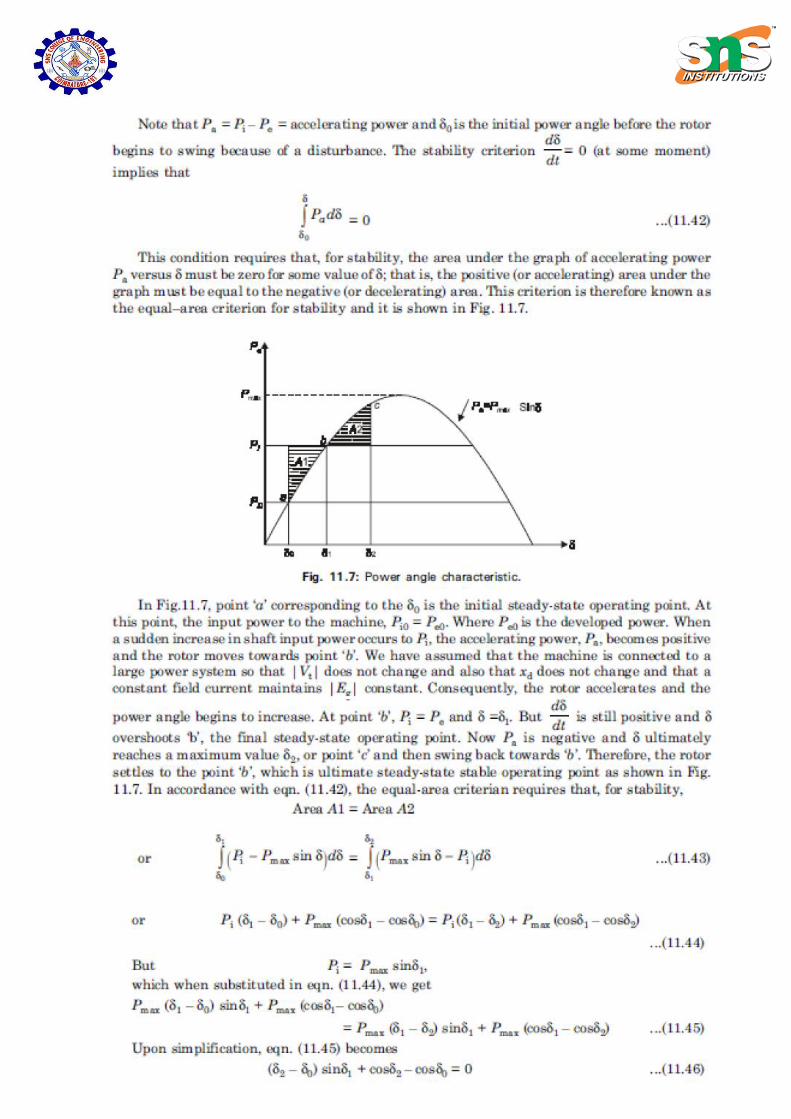
Equal Area Criterion The equal area criterion for stability states that the system is stable if the
area under P – δ curve reduces to zero at some value of δ.

POWER SYSTEM ANALYSIS / R. HARISH /AP/EEE
This is possible if the positive (accelerating) area under P – δ curve is equal
to the negative (decelerating) area under P – δ curve for a finite change in δ.
hence stability criterion is called equal area criterion.
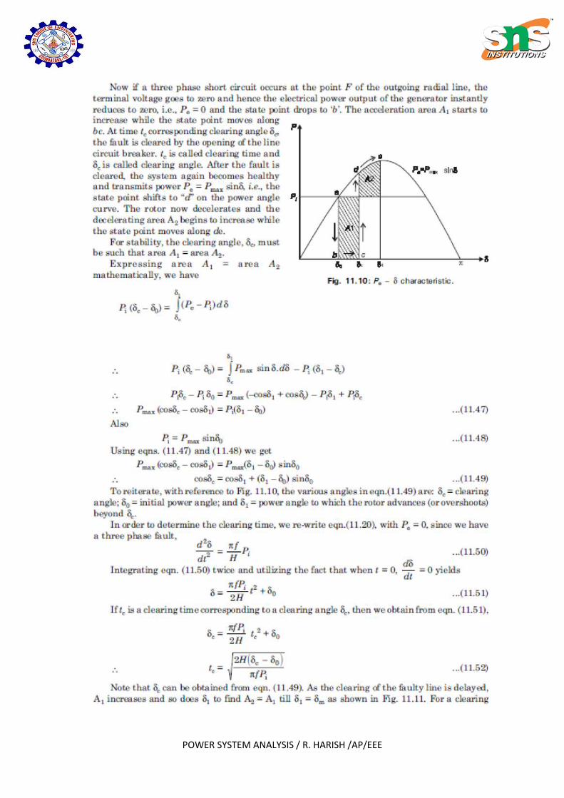
Critical clearing angle. The critical clearing angle , is the maximum allowable change in the
power angle δ before clearing the fault, without loss of synchronism.
The time corresponding to this angle is called critical clearing time, .It
can be defined as the maximum time delay that can be allowed to clear a
fault without loss of synchronism.
Methods of improving the transient stability limit of a power system. Reduction in system transfer reactance
Increase of system voltage and use AVR
Use of high speed excitation systems
Use of high speed reclosing breakers
Numerical integration methods of power system stability i. Point by point method or step by step method
ii. Euler method
iii. Modified Euler method
iv. Runge-Kutta method(R-K method)
Swing Equation for a single machine connected to infinite bus system.

POWER SYSTEM ANALYSIS / R. HARISH /AP/EEE

POWER SYSTEM ANALYSIS / R. HARISH /AP/EEE

POWER SYSTEM ANALYSIS / R. HARISH /AP/EEE
Equal area criterion in transient stability

POWER SYSTEM ANALYSIS / R. HARISH /AP/EEE
POWER SYSTEM ANALYSIS / R. HARISH /AP/EEE
POWER SYSTEM ANALYSIS / R. HARISH /AP/EEE
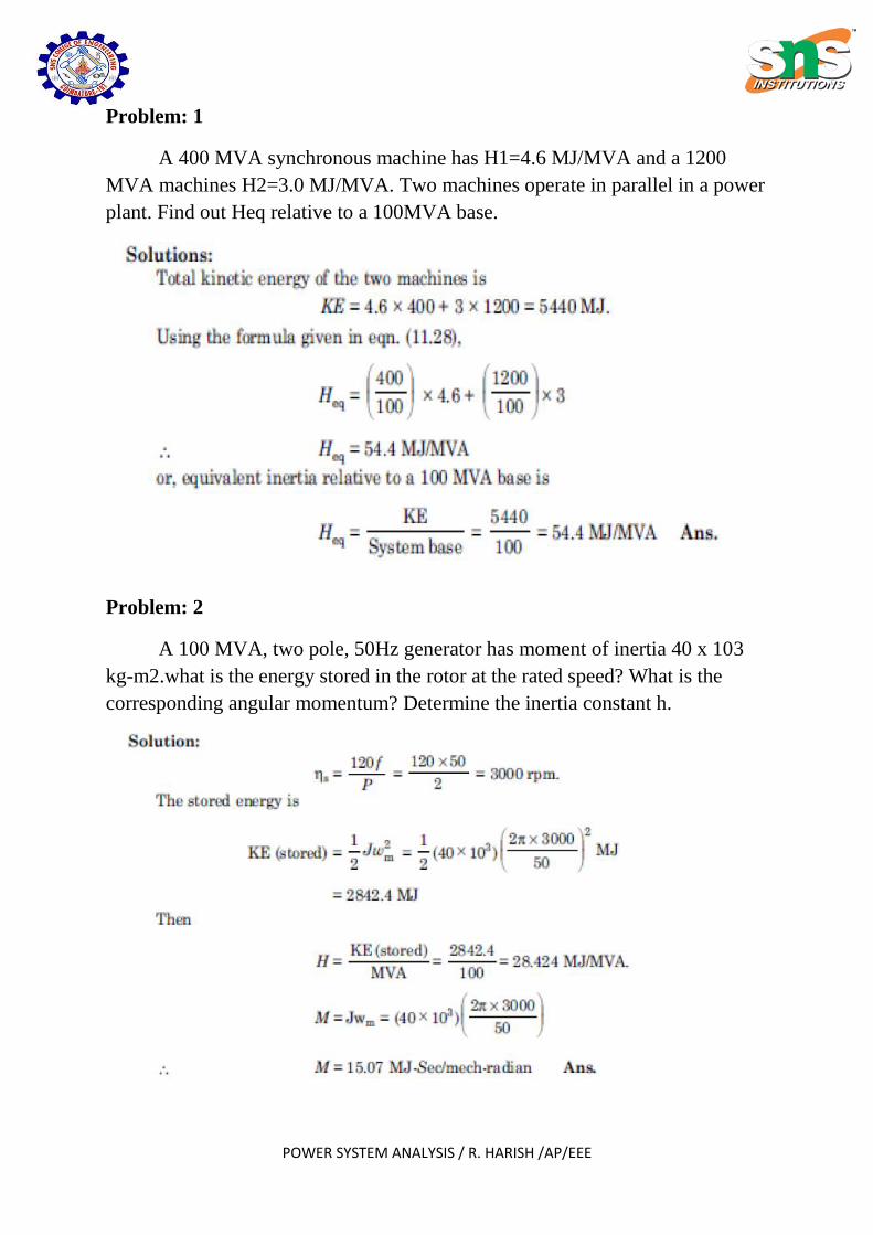
Problem: 1
A 400 MVA synchronous machine has H1=4.6 MJ/MVA and a 1200
MVA machines H2=3.0 MJ/MVA. Two machines operate in parallel in a power
plant. Find out Heq relative to a 100MVA base.
Problem: 2
A 100 MVA, two pole, 50Hz generator has moment of inertia 40 x 103
kg-m2.what is the energy stored in the rotor at the rated speed? What is the
corresponding angular momentum? Determine the inertia constant h.

POWER SYSTEM ANALYSIS / R. HARISH /AP/EEE
Problem: 3
The sending end and receiving end voltages of a three phase transmission
line at a 200MW load are equal at 230KV.The per phase line impedance is j14
ohm. Calculate the maximum steady state power that can be transmitted over
the line.
Problem: 4
A single line diagram of a system is shown in fig. All the values are in
per unit on a common base. The power delivered into bus 2 is 1.0 p.u at 0.80
power factor lagging. Obtain the power angle equation and the swing equation
for the system. Neglect all losses.

POWER SYSTEM ANALYSIS / R. HARISH /AP/EEE
POWER SYSTEM ANALYSIS / R. HARISH /AP/EEE
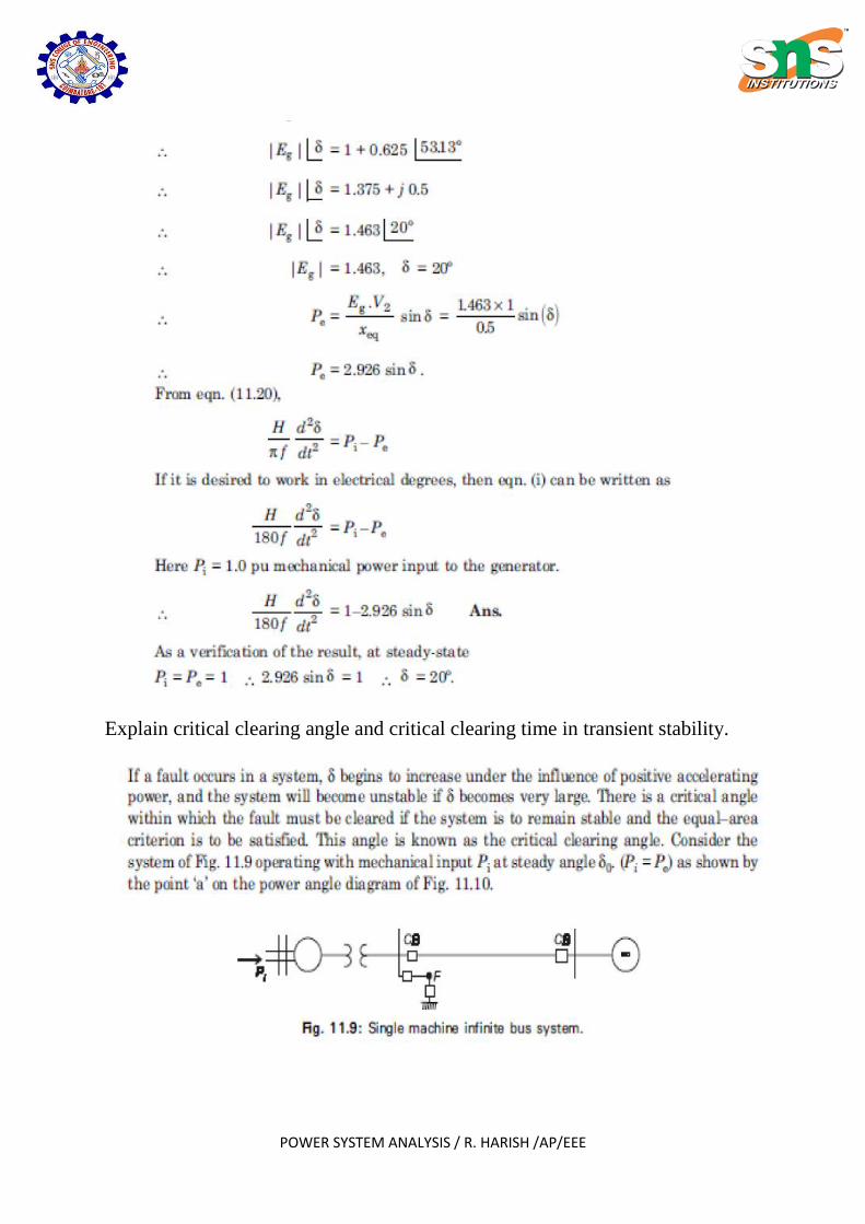
Explain critical clearing angle and critical clearing time in transient stability.
POWER SYSTEM ANALYSIS / R. HARISH /AP/EEE

POWER SYSTEM ANALYSIS / R. HARISH /AP/EEE

POWER SYSTEM ANALYSIS / R. HARISH /AP/EEE
Problem: 5
A 50Hz synchronous generator capable of supplying 400MW of power is
connected to a larger power system and is delivering 80MW when a three phase
fault occurs at its terminals, determine (a) the time in which the fault must be
cleared if the maximum power angle is to be -85˚ assume H=7MJ/MVA on a
100MVA base (b) the critical clearing angle.
POWER SYSTEM ANALYSIS / R. HARISH /AP/EEE
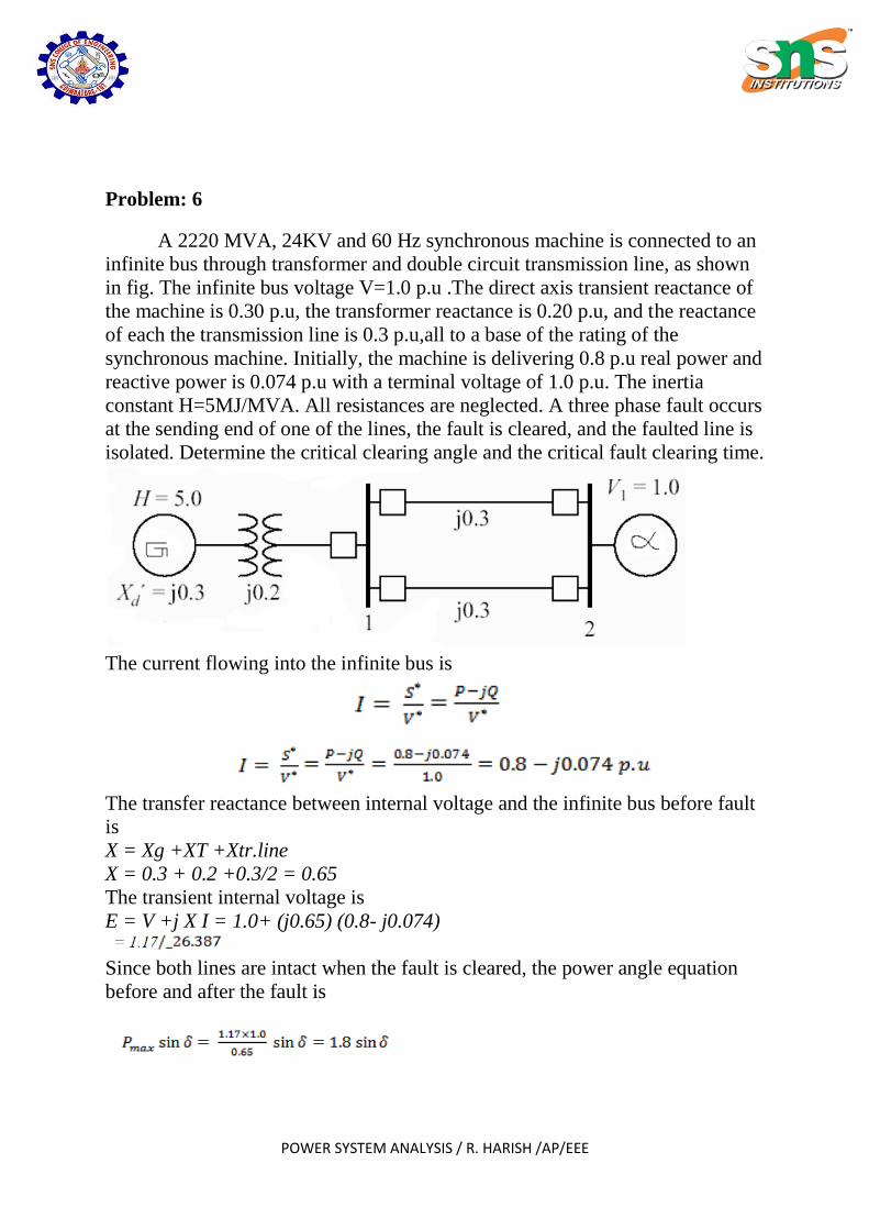
Problem: 6
A 2220 MVA, 24KV and 60 Hz synchronous machine is connected to an
infinite bus through transformer and double circuit transmission line, as shown
in fig. The infinite bus voltage V=1.0 p.u .The direct axis transient reactance of
the machine is 0.30 p.u, the transformer reactance is 0.20 p.u, and the reactance
of each the transmission line is 0.3 p.u,all to a base of the rating of the
synchronous machine. Initially, the machine is delivering 0.8 p.u real power and
reactive power is 0.074 p.u with a terminal voltage of 1.0 p.u. The inertia
constant H=5MJ/MVA. All resistances are neglected. A three phase fault occurs
at the sending end of one of the lines, the fault is cleared, and the faulted line is
isolated. Determine the critical clearing angle and the critical fault clearing time.
The current flowing into the infinite bus is
The transfer reactance between internal voltage and the infinite bus before fault
is
X = Xg +XT +Xtr.line
X = 0.3 + 0.2 +0.3/2 = 0.65
The transient internal voltage is
E = V +j X I = 1.0+ (j0.65) (0.8- j0.074)
Since both lines are intact when the fault is cleared, the power angle equation
before and after the fault is

POWER SYSTEM ANALYSIS / R. HARISH /AP/EEE
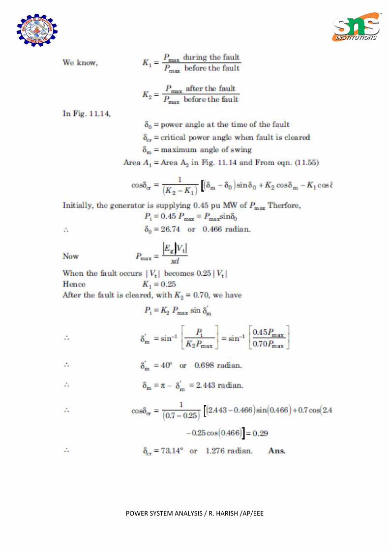
Problem: 7
A synchronous generator is connected to a large power system and
supplying 0.45 pu MW of its maximum power capacity. A three phase fault
occurs and the effective terminal voltage of the generator becomes 25% of its
value before the fault. When the fault is cleared, generator is delivering 70% of
the original maximum value. Determine the critical clearing angle.
POWER SYSTEM ANALYSIS / R. HARISH /AP/EEE

POWER SYSTEM ANALYSIS / R. HARISH /AP/EEE
Problem: 8
Find the critical clearing angle of the power system shown in fig. for a
three phase fault at the point F. Generator is supplying 1.0 p.u MW power under
pre-fault condition.

POWER SYSTEM ANALYSIS / R. HARISH /AP/EEE

POWER SYSTEM ANALYSIS / R. HARISH /AP/EEE

POWER SYSTEM ANALYSIS / R. HARISH /AP/EEE
Factors influencing transient stability
Numerical integration methods of power system stability
Explain any one methods.
v. Point by point method or step by step method
vi. Euler method
vii. Modified Euler method
viii. Runge-Kutta method(R-K method)
POWER SYSTEM ANALYSIS / R. HARISH /AP/EEE
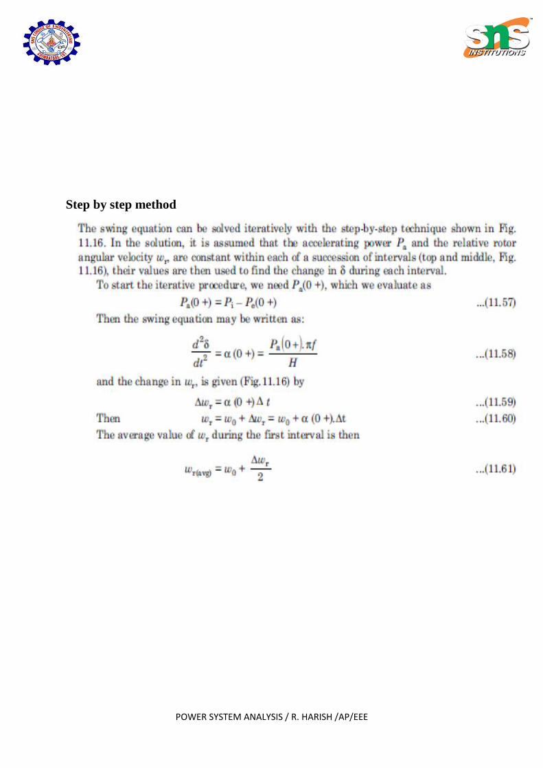
Step by step method

POWER SYSTEM ANALYSIS / R. HARISH /AP/EEE

POWER SYSTEM ANALYSIS / R. HARISH /AP/EEE
Problem: 9