
UNIT I - SNS Courseware
16
SNSCE/ EEE/ EM-II/ UNIT-I / P.SANGEETHA UNIT I - 16 MARK QUESTION & ANSWER 1.Explain the construction of alternators . (Nov 2012,NOV 2016) Synchronous Generators: 1) Synchronous machines are principally used as alternating current (AC) generators. They supply the electric power used by all sectors of modern societies: industrial, commercial, agricultural, and domestic. 2) They usually operate together (or in parallel), forming a large power system supplying electrical energy to the loads or consumers. 3) built in large units, their rating ranging from tens to hundreds of megawatts. 4) converts mechanical power to ac electric power. The source of mechanical power, the prime mover, may be a diesel engine, a steam turbine, a water turbine, or any similar device. - For high-speed machines, the prime movers are usually steam turbines employing fossil or nuclear energy resources. - Low-speed machines are often driven by hydro-turbines that employ water power for generation. According to the arrangement of the field and armature windings, synchronous machines may be classified as rotating-armature type or rotating-field type. 1) Rotating-Armature Type: The armature winding is on the rotor and the field system is on the stator. 2) Rotating-Field Type: The armature winding is on the stator and the field system is on the rotor.According to the shape of the field, synchronous machines may be classified as cylindrical-rotor (non-salient pole) machines and salient-pole machines There are mainly two types of rotor used in construction of alternator, 1. salient pole type 2.cylindrical rotor type
-
Upload
khangminh22 -
Category
Documents
-
view
5 -
download
0
Transcript of UNIT I - SNS Courseware

SNSCE/ EEE/ EM-II/ UNIT-I / P.SANGEETHA
UNIT I - 16 MARK QUESTION & ANSWER
1.Explain the construction of alternators . (Nov 2012,NOV 2016)
Synchronous Generators:
1) Synchronous machines are principally used as alternating current (AC) generators.
They supply the electric power used by all sectors of modern societies: industrial,
commercial, agricultural, and domestic.
2) They usually operate together (or in parallel), forming a large power system
supplying electrical energy to the loads or consumers.
3) built in large units, their rating ranging from tens to hundreds of megawatts.
4) converts mechanical power to ac electric power. The source of mechanical power,
the prime mover, may be a diesel engine, a steam turbine, a water turbine, or any
similar device.
- For high-speed machines, the prime movers are usually steam turbines
employing fossil or nuclear energy resources.
- Low-speed machines are often driven by hydro-turbines that employ water
power for generation.
According to the arrangement of the field and armature windings, synchronous
machines may be classified as rotating-armature type or rotating-field type.
1) Rotating-Armature Type:
The armature winding is on the rotor and the field system is on the stator.
2) Rotating-Field Type:
The armature winding is on the stator and the field system is on the
rotor.According to the shape of the field, synchronous machines may be
classified as cylindrical-rotor (non-salient pole) machines and salient-pole
machines
There are mainly two types of rotor used in construction of alternator,
1. salient pole type
2.cylindrical rotor type

SNSCE/ EEE/ EM-II/ UNIT-I / P.SANGEETHA
Salient Pole Type: The salient pole type of rotor is generally used for slow speed
machines having large diameters and relatively small axial lengths. The pole in this
case are made of thick laminated steel sections riveted together and attached to a rotor
with the help of joint
. An alternator as mentioned earlier is mostly responsible for generation of very
high electrical power. To enable that, the mechanical input given to the machine in
terms of rotating torque must also be very high. This high torque value results in
oscillation or hunting effect of the alternator or synchronous generator.
. The damper windings are basically copper bars short circuited at both ends are
placed in the holes made in the pole axis. When the alternator is driven at a steady
speed, the relative velocity of the damping winding with respect to main field will be
Salient Pole Rotor
zero. But as soon as it departs from the synchronous speed there will be relative motion
between the damper winding and the main field which is always rotating at
synchronous speed. This relative difference will induce current in them which will exert
a torque on the field poles in such a way as to bring the alternator back to synchronous
speed operation.
The salient features of pole field structure has the following special feature-

SNSCE/ EEE/ EM-II/ UNIT-I / P.SANGEETHA
1. They have a large horizontal diameter compared to a shorter axial length.
2. The pole shoes cover only about 2/3rd of pole pitch.
3. Poles are laminated to reduce eddy current loss.
CylindricalRotorType:
The cylindrical rotors are generally used for very high speed operation and are employed in steam turbine driven alternators like turbo generators. The cylindrical rotor type machine has uniform length in all directions, giving a cylindrical shape to the rotor thus providing uniform flux cutting in all directionsThe rotor in this case consists of a smooth solid steel cylinder, having a number of slots along its outer periphery for hosing the field coils.The cylindrical rotor alternators are generally designed for 2-pole type giving very high speed of Ns = (120 × f)/P = (120 × 50) / 2 = 3000 rpm. Or 4-pole type running at a speed of Ns = (120 × f) / P = (120 × 50) / 4 = 1500 rpm. Where f is
Cylindrical Rotor Type
the frequency of 50 Hz. The a cylindrical rotor synchronous generator does not have
any projections coming out from the surface of the rotor, rather central polar area
are provided with slots for housing the field windings as we can see from the
diagram above. The field coils are so arranged around these poles that flux density
is maximum on the polar central line and gradually falls away as we move out
towards the periphery. The cylindrical rotor type machine gives better balance and
quieter-operation along with lesser windage losses.
AC winding design
The windings used in rotating electrical machines can be classified as

SNSCE/ EEE/ EM-II/ UNIT-I / P.SANGEETHA
Concentrated Windings:
- All the winding turns are wound together in series to form one multi-turn coil
- All the turns have the same magnetic axis
Distributed Windings:
- All the winding turns are arranged in several full-pitch or fractional-pitch coils
- These coils are then housed in the slots spread around the air-gap periphery to
form phase or commutator winding
2. Explain EMF method of regulation with OC and SC curves in detail. (Nov
2012,Nov 2016)
Open-circuit characteristic (OCC) of a generator:
With the armature terminals open, Ia=0, so Eg = Vt It is thus possible to
construct a plot of Eg or Vt vs. If graph. This plot is called open-circuit
characteristic (OCC) of a generator. With this characteristic, it is possible to find the
internal generated voltage of the generator for any given field current.
Open-circuit characteristic of alternator
Initially OCC follows a straight-line relation with the field current as long as the
magnetic circuit of the synchronous generator does not saturate. This straight line is
appropriately called the air-gap line. Practically due to saturation induced emf bend
from the straight line.
SNSCE/ EEE/ EM-II/ UNIT-I / P.SANGEETHA
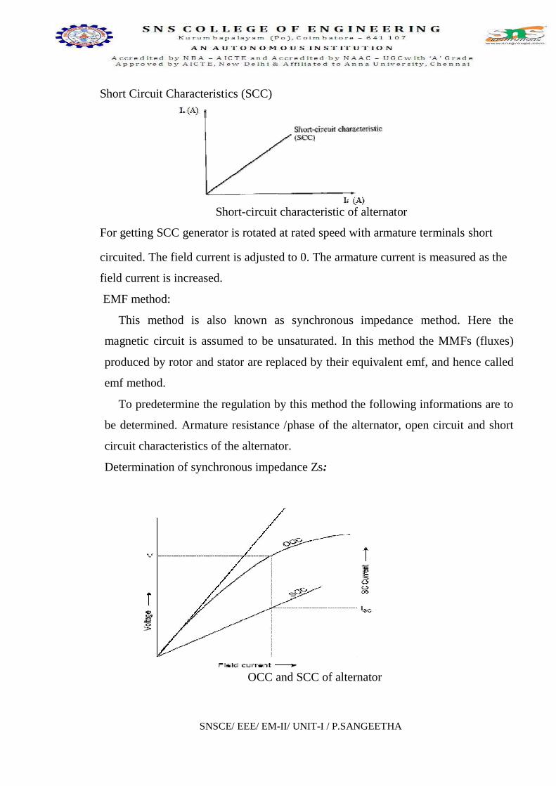
OCC and SCC of alternator
Short Circuit Characteristics (SCC)
Short-circuit characteristic of alternator
For getting SCC generator is rotated at rated speed with armature terminals short
circuited. The field current is adjusted to 0. The armature current is measured as the
field current is increased.
EMF method:
This method is also known as synchronous impedance method. Here the
magnetic circuit is assumed to be unsaturated. In this method the MMFs (fluxes)
produced by rotor and stator are replaced by their equivalent emf, and hence called
emf method.
To predetermine the regulation by this method the following informations are to
be determined. Armature resistance /phase of the alternator, open circuit and short
circuit characteristics of the alternator.
Determination of synchronous impedance Zs:

SNSCE/ EEE/ EM-II/ UNIT-I / P.SANGEETHA
As the terminals of the stator are short circuited in SC test, the short circuit
current is circulated against the impedance of the stator called the synchronous
impedance. This impedance can be estimated form the oc and sc characteristics.
The ratio of open circuit voltage to the short circuit current at a particular field
current, or at a field current responsible for circulating the rated current is called the
synchronous impedance.
Synchronous impedance Zs = (open circuit voltage per phase)/(short circuit current
per phase) for same If
Hence Zs = (Voc) / (Isc) for same If
Armature resistance Ra of the stator can be measured using Voltmeter – Ammeter
method. Using synchronous impedance and armature resistance synchronous
reactance and hence regulation can be calculated as follows using emf method.
Zs = a)2 + (XS)2]and Synchronous reactance Xs = 2 - (Ra)2]
Hence induced emf per phase can be found as Eg = 2
IaXS)2]
where Vt = phase voltage per phase = Vph , Ia = load current per phase
In the above expression in second term + sign is for lagging power factor and – sign
is for leading power factor.
where Eg = no-load induced emf /phase, Vt = rated terminal
voltage/phase. Synchronous impedance method is easy but it gives approximate
results. This method gives the value of regulation which is greater (poor) than the
actual value and hence this method is called pessimistic method.
3. Explain slip test ? Explain the method of measurement of direct axis
reactance and quardrature axis reactance of a Salient pole
alternator.(Nov2015)Blondel Theory
In case salient pole machines the air gap is non uniform and it is smaller along
pole axis and is larger along the inter polar axis. These axes are called direct axis or

SNSCE/ EEE/ EM-II/ UNIT-I / P.SANGEETHA
d-axis and quadrature axis or q-axis. Hence the effect of mmf when acting along
direct axis will be different than that when it is acting along quadrature axis. Hence
the reactance of the stator cannot be same when the mmf is acting along d – axis and
q- axis. As the length of the air gap is small along direct axis reluctance of the
magnetic circuit is less and the air gap along the q – axis is larger and hence the
along the quadrature axis will be comparatively higher. Hence along d-axis more
flux is produced than q-axis. Therefore the reactance due to armature reaction will
be different along d-axis and q-axis. These reactances are,
Xad = direct axis reactance; Xaq = quadrature axis reactance
Hence the effect of armature reaction in the case of a salient pole synchronous
machine can be taken as two components - one acting along the direct axis
(coinciding with the main field pole axis) and the other acting along the quadrature
axis (inter-polar region or magnetic neutral axis) and as such the mmf components
of armature-reaction in a salient-pole machine cannot be considered as acting on the
same magnetic circuit. Hence the effect of the armature reaction cannot be taken into
account by considering only the synchronous reactance, in the case of a salient pole
synchronous machine.
In fact, the direct-axis component Fad acts over a magnetic circuit identical with
that of the main field system and produces a comparable effect while the quadrature-
axis component Faq acts along the interpolar axis, resulting in an altogether smaller
effect and, in addition, a flux distribution totally different from that of Fad or the
main field m.m.f. This explains why the application of cylindrical-rotor theory to
salient-pole machines for predicting the performance gives results not conforming to
the performance obtained from an actual test.
Direct-axis and Quadrature-axis Synchronous Reactances:
Blondel -reaction theory considers the effects of the quadrature and direct-axis
components of the armature reaction separately. Neglecting saturation, their
different effects are considered by assigning to each an appropriate value of
armature-reaction “reactance,” respectively xad and xaq . The effects of armature
resistance and true leakage reactance (XL) may be treated separately, or may be
SNSCE/ EEE/ EM-II/ UNIT-I / P.SANGEETHA
added to the armature reaction coefficients on the assumption that they are the same,
for either the direct-axis or quadrature-axis components of the armature current
(which is almost true). Thus the combined reactance values can be expressed as,
Xsd = xad + x, and Xsq = xaq + x, for the direct- and cross-reaction axes
respectively.
In a salient-pole machine, xaq, the quadrature-axis reactance is smaller than xad, the
direct-axis reactance, since the flux produced by a given current component in that
axis is smaller as the reluctance of the magnetic path consists mostly of the
interpolar spaces. It is essential to clearly note the difference between the quadrature
and direct-axis components Iaq, and Iad of the armature current Ia, and the reactive
and active components Iaa and Iar. Although both pairs are represented by phasors
in phase quadrature, the former are related to the induced emf Et while the latter are
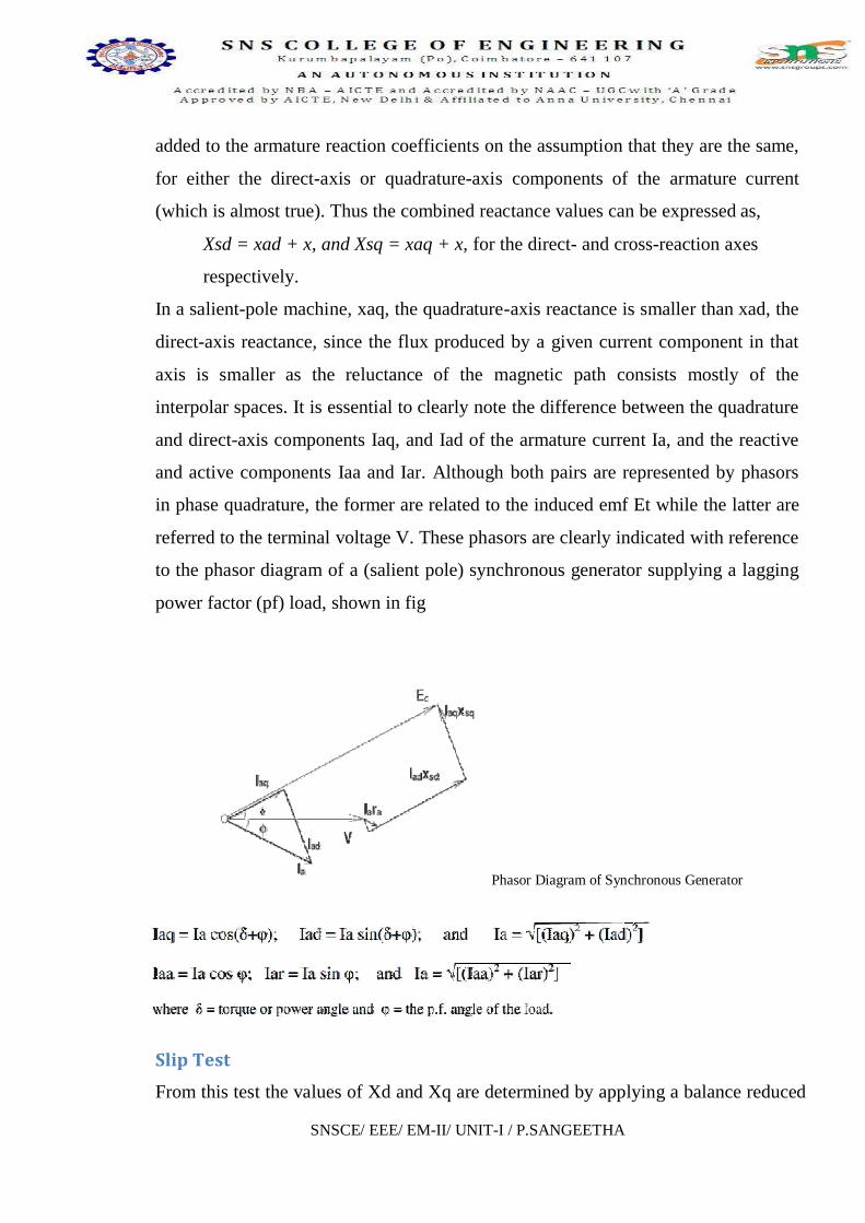
referred to the terminal voltage V. These phasors are clearly indicated with reference
to the phasor diagram of a (salient pole) synchronous generator supplying a lagging
power factor (pf) load, shown in fig
Phasor Diagram of Synchronous Generator
SlipTest
From this test the values of Xd and Xq are determined by applying a balance reduced

SNSCE/ EEE/ EM-II/ UNIT-I / P.SANGEETHA
Due to voltage V applied to the stator terminal a current I will flow causing a
external voltage (say, V volts, around 25% of rated value) to the armature. The field
winding remains unexcited. The machine is run at a speed a little less than the
synchronous speed (the slip being less than 1%) using a prime mover (or motor).
Connection diagram is shown in circuit diagram.
stator mmf. This stator mmf moves slowly relative to the poles and induced an emf
in the field circuit in a similar fashion to that of rotor in an induction motor at slip
frequency. The effect will be that the stator mmf will moves slowly relative to the
poles.The physical poles and the armature-reaction mmf are alternately in phase and
out, the change occurring at slip frequency. When the axis of the pole and the axis of
the armature reaction mmf wave coincide, the armature mmf acts through the field
magnetic circuit. Since the applied voltage is constant, the air-gap flux would be
constant. When crest of the rotating armature mmf is in line with the field-pole axis,
minimum air-gap offers minimum reluctance thus the current required in armature
for the establishment of constant air-gap flux must be minimum. Constant applied
voltage minus the minimum impedance voltage drop in the armature terminal gives
maximum armature terminal voltage.

SNSCE/ EEE/ EM-II/ UNIT-I / P.SANGEETHA
Xd =Maximum armature terminal voltage per phase
Minimum armature current per phase
Similarly
Xq =Minimum armature terminal voltage per phase
Maximum armature current per phase
4. Explaintheparalleloperationoftwoalternators.(Nov2012)Parallel Operation of Alternators:
The operation of connecting an alternator in parallel with another alternator
or with common bus-bars is known as synchronizing. Generally, alternators are
used in a power system where they are in parallel with many other alternators. It
means that the alternator is connected to a live system of constant voltage and
constant frequency. Often the electrical system, to which the alternator is
connected, has already so many alternators and loads connected to it that no
matter what power is delivered by the incoming alternator, the voltage and
frequency of the system remain the same. In that case, the alternator is said to be
connected to infinite bus-bars.
For proper synchronization of alternators, the following four conditions must be
satisfied
1. The terminal voltage (effective) of the incoming alternator must be the same
as bus-bar voltage.
2. The speed of the incoming machine must be such that its frequency (= PN/60)
equals bus-bar frequency.
3. The phase of the alternator voltage must be identical with the phase of the
bus-bar voltage.
4. The phase angle between identical phases must be zero.
It means that the switch must be closed at (or very near) the instant the two voltages
have correct phase relationship.
Condition (1) is indicated by a voltmeter, conditions (2), (3) and (4) are indicated by
synchronizing lamps or a synchronoscope.

SNSCE/ EEE/ EM-II/ UNIT-I / P.SANGEETHA
The synchronizing lamp method is consists of 3 lamps connected between the
phases of the running 3-ph generator and the incoming generator .
In three phase alternators, it is necessary to synchronize one phase only, the
other two phases be will then synchronized automatically.
Synchronisation of two alternators
Two set of star vectors will rotate at unequal speeds if the frequencies of the two are
different. If the incoming alternator is running faster, then voltage star R appear to
rotate anticlockwise with respect to the bus-bar voltage star RYB at a speed
corresponding to the difference between their frequencies. With reference to Fig: 2.6, it
is seen that voltage across L1 is RR to be increasing from zero, and that across L2 is
YB which is decreasing, having just passed through its maximum, and that across L3
BY which is increasing and approaching its maximum. Hence the lamps will light up

SNSCE/ EEE/ EM-II/ UNIT-I / P.SANGEETHA
one after the other in the order 2, 3, 1,2,3,1 or 1, 2, 3. If the incoming alternator is
running slower, then the sequence of light up will be 1, 3, 2. Synchronization is done at
the moment the uncrossed lamp L1 is in the middle of the dark period and other two
lamps are equally bright. Hence this method of synchronization is known as two bright
one dark lamp method.
It should be noted that synchronization by lamps is not quite accurate, because to a
large extent, it depends on the sense of correct judgment of the operator. Hence, to
eliminate the element of personal judgment in routine operation of alternators, the
machines are synchronized by a more accurate device called a synchronoscope. It
consists of 3 stationary coils and a rotating iron vane which is attached to a pointer. Out
of three coils, a pair is connected to one phase of the line and the other to the
corresponding machine terminals, potential transformer being usually used. The pointer
moves to one side or the other from its vertical position depending on whether the
incoming machine is too fast or too slow. For correct speed, the pointer points
vertically up.
5. Explain the Armature Reaction in Alternator or Synchronous Generator (May 2012)
Every rotating electrical machine works based on Faraday s law. Everyelectrical
machine requires a magnetic field and a coil (Known as armature) with a relative motion
between them. In case of an alternator, we supply electricity to pole to produce magnetic
field and output power is taken from the armature. Due to relative motion between field
and armature, the conductor of armatures cut the flux of magnetic field and hence there
would be changing flux linkage with these armature conductor. According to Faraday's
law of electromagnetic induction there would be an emf induced in the armature.
soon as the load is connected with armature terminals, there is an current flowing in the
armature coil. As soon as current starts flowing through the armature conductor there is
one reverse effect of this current on the main field flux of the alternator (or synchronous
generator). This reverse effect is referred as armature reaction in alternator or synchronous
generator.

SNSCE/ EEE/ EM-II/ UNIT-I / P.SANGEETHA
Armature Reaction in Alternator:
In an alternator like all other synchronous machines, the effect of armature
reaction depends on the power factor i.e the phase relationship between the terminal
voltage and armature current. Reactive power (lagging) is the magnetic field energy, so if the
generator supplies a lagging load, this implies that it is supplying magnetic energy to
the load. Since this power comes from excitation of synchronous machine, the net
reactive power gets reduced in the generator. Hence, the armature reaction is
demagnetizing in nature. Similarly, the armature reaction has magnetizing effect when
the generator supplies a leading load (as leading load takes the leading VAR ) and in
return gives lagging VAR (magnetic energy)to the generator. In case of purely resistive
load, the armature reaction is cross magnetizing only.
The armature reaction of alternator or synchronous generator, depends upon the
phase angle between, stator armature current and induced voltage across the armature
winding of alternator. The phase difference between these two quantities, i.e. Armature
current and voltage may vary from - 90° to + 90° If this angle is then,
To understand actual effect of this angle on armature reaction of
alternator, we will consider three standard cases,
1. 0
2. 90°
3. - 90°
Armature Reaction of Alternator at Unity Power Factor
At unity power factor, the angle between armature current I and induced emf E, is
zero. That means, armature current and induced emf are in same phase. But we know
theoretically that emf induced in the armature is due to changing main field flux, linked

SNSCE/ EEE/ EM-II/ UNIT-I / P.SANGEETHA
with the armature conductor. As field is excited by DC, the main field flux is constant
in respect to field magnets, but it would be alternating in respect of armature as there is
a relative motion between field and armature in alternator. If main field flux of the
alternator in respect of armature can be represented as
Then induced emf E across the armature is proportional to, f/dt.
Hence, from this above equations (1) and (2) it is clear that, the angle between,
&phif a is proportional to armature
current a is in phase with armature current I. Again at unity
electrical power factor a is phase with E. So at
this condition, armature flux is in phase with induced emf E and field flux is in
a f. As
this two fluxes are perpendicular to each other, the armature reaction of alternator at unity
power factor is purely distorting or cross-magnetizing type.
As the armature flux pushes the main field flux perpendicularly, distribution of
main field flux under a pole face does not remain uniformly distributed. The flux
density under the trailing pole tips increases somewhat while under the leading pole tips
it decreases.
Armature Reaction of Alternator at Lagging Zero Power Factor
At lagging zero electrical power factor, the armature current lags by 90° to induced
emf in the armature. As the emf induced in the armature coil due to main field flux. The
emf leads the main field flux by 90°. From equation (1) we get, the field flux, Hence, at
f f has maximum value.
f zero. f has negative
maximum value.
f f leads E by 90°. Now,

SNSCE/ EEE/ EM-II/ UNIT-I / P.SANGEETHA
armature current I is proportional a, and I lags E by 90°. Hence, a
f leads E by 90°. Therefore,
armature flux and field flux act directly opposite to each other. Thus, armature reaction
of alternator at lagging zero power factor is purely demagnetizing type. That means,
armature flux directly weakens main field flux.
Armature Reaction of Alternator at Leading Power Factor
At leading power factor condition, armature current I leads induced emf E by an
f leads, induced emf E by 90°. Again,
a is proportional to armature current I. a is in phase with I.
a also leads E, by 90° as I leads E by 90°. As in this case both
armature flux and field flux lead induced emf E by 90°, it can be said, field flux and
armature flux are in same direction. Hence, the resultant flux is simply arithmetic sum
of field flux and armature flux. Hence, at last it can be said that, armature reaction of
alternator due to a purely leading electrical power factor is totally magnetizing type.
6.DerivetheEMFequationofAlternator. (Nov2012,Nov2016)Let P be the number of poles.
Ns be the synchronous speed.
Z be the number of conductors.
Zph be the number of conductors per phase.
Zph=Z/3
Tph= Zph /2
Kc= Distribution factor
Kd= Coil span factor or pitch factor
Kf=Form factor=1.11
By faradays Law, for single conductor,
---------- (1)
dt=60/N --------- (2)

SNSCE/ EEE/ EM-II/ UNIT-I / P.SANGEETHA
Sub (1) and (2)
E = =
We know that, Subs in above Equation,
Consider a single turn,
Eturn = 2* =
If there are Tph Total number of turns/phase, then
Average emf in turns/phase = Tph *
RMS value of Average emf in turns/phase = Average emf in turns/phase* Form factor
= Tph *1.11*
Eph = 4.44 f ph
Generalized emf equation is given by,
Eph= 4.44f*Kc*Kd* ph(volts)