Velocity triangles - SNS Courseware
12
SNS COLLEGE OF TECHNOLOGY, COIMBATORE-35 DEPARTMENT OF MECHANICAL ENGINEERING Fluid Mechanics and Machinery – UNIT IV TURBINES Topic - Velocity triangles - Axial, radial and mixed flow turbines Velocity triangles It is the component which is responsible for “actual work done” across blades. The jet of fluid that strikes the turbine blades, has its two components: 1. Whirl component 2. Axial thrust The whirl velocity is the tangential component of absolute velocity at the blade inlet and outlet. This component of velocity is responsible for the whirling or rotating of the turbine rotor. Otherwise In turbomachinery, a velocity triangle or a velocity diagram is a triangle representing the various components of velocities of the working fluid in a turbomachine. Velocity triangles may be drawn for both the inlet and outlet sections of any turbomachine. The vector nature of velocity is utilized in the triangles, and the most basic form of a velocity triangle consists of the tangential velocity, the absolute velocity and the relative velocity of the fluid making up three sides of the triangle. A general velocity triangle consists of the following vectors: V : Absolute Velocity of The Fluid. U : Blade Linear Velocity. Vr: Relative Velocity of The Fluid After Contact With Rotor. Vw: Tangential Component of V (Absolute Velocity), Called Whirl Velocity. Vf: Flow Velocity (Axial Component In Case of Axial Machines, Radial Component In Case of Radial Machines). The Following Angles Are Encountered During The Analysis: Α: Angle Made by V With The Plane of The Machine (Usually The Nozzle Angle or The Guide Blade Angle). Β: Angle of The Rotor Blade. Absolute Angle
-
Upload
khangminh22 -
Category
Documents
-
view
2 -
download
0
Transcript of Velocity triangles - SNS Courseware

SNS COLLEGE OF TECHNOLOGY, COIMBATORE-35 DEPARTMENT OF MECHANICAL ENGINEERING
Fluid Mechanics and Machinery –
UNIT IV TURBINES Topic - Velocity triangles - Axial, radial and mixed flow turbines
Velocity triangles
It is the component which is responsible for “actual work done” across blades.
The jet of fluid that strikes the turbine blades, has its two components:
1. Whirl component
2. Axial thrust
The whirl velocity is the tangential component of absolute velocity at the blade inlet and
outlet. This component of velocity is responsible for the whirling or rotating of the turbine
rotor.
Otherwise
In turbomachinery, a velocity triangle or a velocity diagram is a triangle representing the
various components of velocities of the working fluid in a turbomachine.
Velocity triangles may be drawn for both the inlet and outlet sections of any turbomachine.
The vector nature of velocity is utilized in the triangles, and the most basic form of a
velocity triangle consists of the tangential velocity, the absolute velocity and the relative
velocity of the fluid making up three sides of the triangle.
A general velocity triangle consists of the
following vectors:
V : Absolute Velocity of The Fluid.
U : Blade Linear Velocity.
Vr: Relative Velocity of The Fluid After
Contact With Rotor.
Vw: Tangential Component of V (Absolute
Velocity), Called Whirl Velocity.
Vf: Flow Velocity
(Axial Component In Case of Axial Machines,
Radial Component In Case of Radial
Machines).
The Following Angles Are Encountered During
The Analysis:
Α: Angle Made by V With The Plane of The
Machine (Usually The Nozzle Angle or The
Guide Blade Angle).
Β: Angle of The Rotor Blade. Absolute Angle

SNS COLLEGE OF TECHNOLOGY, COIMBATORE-35 DEPARTMENT OF MECHANICAL ENGINEERING
Fluid Mechanics and Machinery –
UNIT IV TURBINES Topic - Velocity triangles - Axial, radial and mixed flow turbines

SNS COLLEGE OF TECHNOLOGY, COIMBATORE-35 DEPARTMENT OF MECHANICAL ENGINEERING
Fluid Mechanics and Machinery –
UNIT IV TURBINES Topic - Velocity triangles - Axial, radial and mixed flow turbines
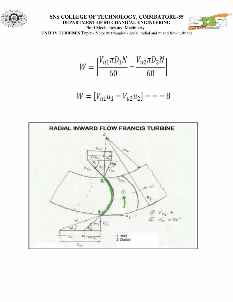
Vu2 = Whirl component of absolute velocity at outlet;
Vf2 = Flow component of absolute velocity at outlet ; Inlet and Outlet Velocity Triangles
Referring to velocity triangles
1 – Inlet, 2 – outlet
V1 = Absolute velocity of the fluid at inlet (before entering the rotor vanes)
Vr1 = Relative velocity of the fluid at rotor inlet
Vu1 = Tangential component of absolute velocity
OR
Whirl component of velocity at inlet
Vru2 = Whirl component of relative velocity at outlet
U2 = Linear rotor velocity at outlet
1 = Fluid or jet angle at outlet (To the direction of wheel rotation)
1 = Vane (blade) angle at outlet (To the direction of wheel rotation)
Vf1 = Flow component of absolute velocity at inlet
Vru1 = Whirl component of relative velocity at inlet
U1 = Linear rotor vane velocity at inlet
1= Absolute jet angle at inlet
1 = Vane (blade) angle at inlet
Referring to outlet velocity triangle

SNS COLLEGE OF TECHNOLOGY, COIMBATORE-35 DEPARTMENT OF MECHANICAL ENGINEERING
Fluid Mechanics and Machinery –
UNIT IV TURBINES Topic - Velocity triangles - Axial, radial and mixed flow turbines

SNS COLLEGE OF TECHNOLOGY, COIMBATORE-35 DEPARTMENT OF MECHANICAL ENGINEERING
Fluid Mechanics and Machinery –
UNIT IV TURBINES Topic - Velocity triangles - Axial, radial and mixed flow turbines
SNS COLLEGE OF TECHNOLOGY, COIMBATORE-35 DEPARTMENT OF MECHANICAL ENGINEERING
Fluid Mechanics and Machinery –
UNIT IV TURBINES Topic - Velocity triangles - Axial, radial and mixed flow turbines

SNS COLLEGE OF TECHNOLOGY, COIMBATORE-35 DEPARTMENT OF MECHANICAL ENGINEERING
Fluid Mechanics and Machinery –
UNIT IV TURBINES Topic - Velocity triangles - Axial, radial and mixed flow turbines

SNS COLLEGE OF TECHNOLOGY, COIMBATORE-35 DEPARTMENT OF MECHANICAL ENGINEERING
Fluid Mechanics and Machinery –
UNIT IV TURBINES Topic - Velocity triangles - Axial, radial and mixed flow turbines
SNS COLLEGE OF TECHNOLOGY, COIMBATORE-35 DEPARTMENT OF MECHANICAL ENGINEERING
Fluid Mechanics and Machinery –
UNIT IV TURBINES Topic - Velocity triangles - Axial, radial and mixed flow turbines

SNS COLLEGE OF TECHNOLOGY, COIMBATORE-35 DEPARTMENT OF MECHANICAL ENGINEERING
Fluid Mechanics and Machinery –
UNIT IV TURBINES Topic - Velocity triangles - Axial, radial and mixed flow turbines

SNS COLLEGE OF TECHNOLOGY, COIMBATORE-35 DEPARTMENT OF MECHANICAL ENGINEERING
Fluid Mechanics and Machinery –
UNIT IV TURBINES Topic - Velocity triangles - Axial, radial and mixed flow turbines

SNS COLLEGE OF TECHNOLOGY, COIMBATORE-35 DEPARTMENT OF MECHANICAL ENGINEERING
Fluid Mechanics and Machinery –
UNIT IV TURBINES Topic - Velocity triangles - Axial, radial and mixed flow turbines
Question and answers: -
Draw velocity triangles at inlet and outlet of typical Francis turbine vane.
Ans. There are three types of velocity triangles for. inlet and outlet in Francis turbine. Triangles are made for slow runner, medium runner and fast runner.
Fig. Slow runner
Fig. Medium Runner
Fig. Fast Runner