Neural network predictive control of UPFC for improving transient stability performance of power...
10
Applied Soft Computing 11 (2011) 4581–4590 Contents lists available at ScienceDirect Applied Soft Computing j ourna l ho mepage: www.elsevier.com/locate/asoc Neural network predictive control of UPFC for improving transient stability performance of power system Sheela Tiwari a,∗ , Ram Naresh b , R. Jha a a Department of Instrumentation and Control Engineering, Dr. B R Ambedkar National Institute of Technology, Jalandhar, Punjab, India b Department of Electrical Engineering, National Institute of Technology, Hamirpur, Himachal Pradesh, India a r t i c l e i n f o Article history: Received 27 August 2010 Received in revised form 13 May 2011 Accepted 1 August 2011 Available online 11 August 2011 Keywords: Neural networks Predictive control Identification Power system transient stability Unified power flow controller (UPFC) a b s t r a c t This paper presents a neural network predictive controller for the UPFC to improve the transient stability performance of the power system. A neural network model for the power system is trained using the back- propagation learning method employing the Levenberg–Marquardt algorithm for faster convergence. This neural identifier is then utilized during predictive control of the UPFC. The damped Gauss–Newton method employing ‘backtracking’ as the line search method for step selection is used by the predictive controller to predict the future control inputs. The 4- machine 2-area power system which is a bench- mark power system is used to demonstrate the performance of the proposed controller. The system under consideration is simulated for different transients over a range of operating conditions using Mat- lab/Simulink. The proposed neural network predictive controller exhibits superior damping performance in comparison to the conventional PI controller. The simulation results also establish convergence of the minimization algorithm to an acceptable solution within single iteration. © 2011 Elsevier B.V. All rights reserved. 1. Introduction With the increase in electrical power demand, power systems are increasingly becoming complex to operate and at the same time less secure. Such a stressed system is continuously under threat of losing stability following a disturbance. Though power system sta- bilizers (PSSs) have been commonly employed for damping rotor oscillations but the damping provided by the PSS has been found to be inadequate under many operating conditions. This inadequacy in damping the rotor oscillations is especially prominent in inter- area oscillations, thereby resulting into a requirement of some additional control. In recent times, the availability of high power semiconductor devices for power system applications have led to technologies such as Flexible AC Transmission Systems (FACTS) for secure loading, power flow control and damping of power system oscillations. The FACTS devices have emerged as effective alter- natives of the additional control required for damping the power system oscillations. Of all the FACTS devices, the unified power flow controller (UPFC) is the most versatile and capable of providing stability to the system subjected to transient disturbances due to its ability to control, simultaneously or selectively, all the param- eters affecting power flow in the transmission line, i.e. voltage, impedance and phase angle [1]. ∗ Corresponding author. Tel.: +91 9779090688. E-mail address: [email protected] (S. Tiwari). Numerous control strategies have been reported for using the UPFC effectively. The most commonly employed controllers for the UPFC have been of the PID (Proportional + Integral + Derivative) type because of their simplicity and ease in design. However, these controllers suffer from a serious drawback in the form of deteri- oration in the performance when the system is made to operate under widely ranging operating conditions and subjected to tran- sients. To overcome this drawback, controllers based on robust control techniques [2–5] and direct methods [6–8] have been used. A model-free approach providing non-linear control is offered by the fuzzy logic approach and is reported in the literature [9–12]. Neural networks offer alternatives to the conventional linear and non-linear control methods. They have an inherent capability to learn and store information regarding the non-linearities of the system and provide this information whenever required. This ren- ders the neural networks suitable for system identification and control applications [8,13–16]. Two separate continually online- trained neurocontrollers employing neuroidentifiers are reported [14] where the parameters of both the neuroidentifiers and neuro- controllers were updated continuously based on the error only one time step ahead. However, this adaptation is based on a short term goal and may not ensure a long term satisfactory performance. A single neuron radial basis function neural network (RBFNN) using H∞-learning method has been reported [15] to improve transient stability performance of power system. However, this work uses a genetic optimization scheme to optimize a set of coefficients in the described method which may increase the computation time. 1568-4946/$ – see front matter © 2011 Elsevier B.V. All rights reserved. doi:10.1016/j.asoc.2011.08.003
-
Upload
independent -
Category
Documents
-
view
2 -
download
0
Transcript of Neural network predictive control of UPFC for improving transient stability performance of power...
Np
Sa
b
a
ARRAA
KNPIPU
1
allbobiaastsonscsiei
1d
Applied Soft Computing 11 (2011) 4581–4590
Contents lists available at ScienceDirect
Applied Soft Computing
j ourna l ho mepage: www.elsev ier .com/ locate /asoc
eural network predictive control of UPFC for improving transient stabilityerformance of power system
heela Tiwaria,∗, Ram Nareshb, R. Jhaa
Department of Instrumentation and Control Engineering, Dr. B R Ambedkar National Institute of Technology, Jalandhar, Punjab, IndiaDepartment of Electrical Engineering, National Institute of Technology, Hamirpur, Himachal Pradesh, India
r t i c l e i n f o
rticle history:eceived 27 August 2010eceived in revised form 13 May 2011ccepted 1 August 2011vailable online 11 August 2011
a b s t r a c t
This paper presents a neural network predictive controller for the UPFC to improve the transient stabilityperformance of the power system. A neural network model for the power system is trained using the back-propagation learning method employing the Levenberg–Marquardt algorithm for faster convergence.This neural identifier is then utilized during predictive control of the UPFC. The damped Gauss–Newtonmethod employing ‘backtracking’ as the line search method for step selection is used by the predictive
eywords:eural networksredictive controldentificationower system transient stabilitynified power flow controller (UPFC)
controller to predict the future control inputs. The 4- machine 2-area power system which is a bench-mark power system is used to demonstrate the performance of the proposed controller. The systemunder consideration is simulated for different transients over a range of operating conditions using Mat-lab/Simulink. The proposed neural network predictive controller exhibits superior damping performancein comparison to the conventional PI controller. The simulation results also establish convergence of theminimization algorithm to an acceptable solution within single iteration.
. Introduction
With the increase in electrical power demand, power systemsre increasingly becoming complex to operate and at the same timeess secure. Such a stressed system is continuously under threat ofosing stability following a disturbance. Though power system sta-ilizers (PSSs) have been commonly employed for damping rotorscillations but the damping provided by the PSS has been found toe inadequate under many operating conditions. This inadequacy
n damping the rotor oscillations is especially prominent in inter-rea oscillations, thereby resulting into a requirement of somedditional control. In recent times, the availability of high poweremiconductor devices for power system applications have led toechnologies such as Flexible AC Transmission Systems (FACTS) forecure loading, power flow control and damping of power systemscillations. The FACTS devices have emerged as effective alter-atives of the additional control required for damping the powerystem oscillations. Of all the FACTS devices, the unified power flowontroller (UPFC) is the most versatile and capable of providingtability to the system subjected to transient disturbances due to
ts ability to control, simultaneously or selectively, all the param-ters affecting power flow in the transmission line, i.e. voltage,mpedance and phase angle [1].∗ Corresponding author. Tel.: +91 9779090688.E-mail address: [email protected] (S. Tiwari).
568-4946/$ – see front matter © 2011 Elsevier B.V. All rights reserved.oi:10.1016/j.asoc.2011.08.003
© 2011 Elsevier B.V. All rights reserved.
Numerous control strategies have been reported for using theUPFC effectively. The most commonly employed controllers forthe UPFC have been of the PID (Proportional + Integral + Derivative)type because of their simplicity and ease in design. However, thesecontrollers suffer from a serious drawback in the form of deteri-oration in the performance when the system is made to operateunder widely ranging operating conditions and subjected to tran-sients. To overcome this drawback, controllers based on robustcontrol techniques [2–5] and direct methods [6–8] have been used.A model-free approach providing non-linear control is offered bythe fuzzy logic approach and is reported in the literature [9–12].Neural networks offer alternatives to the conventional linear andnon-linear control methods. They have an inherent capability tolearn and store information regarding the non-linearities of thesystem and provide this information whenever required. This ren-ders the neural networks suitable for system identification andcontrol applications [8,13–16]. Two separate continually online-trained neurocontrollers employing neuroidentifiers are reported[14] where the parameters of both the neuroidentifiers and neuro-controllers were updated continuously based on the error only onetime step ahead. However, this adaptation is based on a short termgoal and may not ensure a long term satisfactory performance. Asingle neuron radial basis function neural network (RBFNN) using
H∞-learning method has been reported [15] to improve transientstability performance of power system. However, this work uses agenetic optimization scheme to optimize a set of coefficients in thedescribed method which may increase the computation time.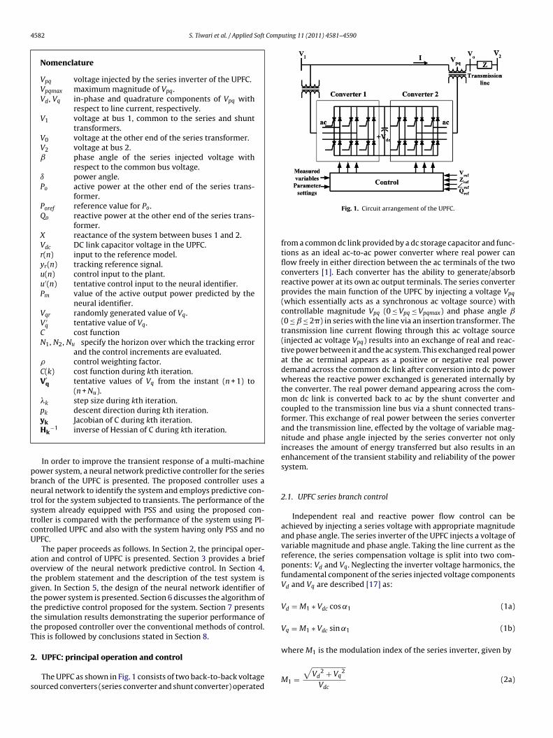
4582 S. Tiwari et al. / Applied Soft Computing 11 (2011) 4581–4590
Nomenclature
Vpq voltage injected by the series inverter of the UPFC.Vpqmax maximum magnitude of Vpq.Vd, Vq in-phase and quadrature components of Vpq with
respect to line current, respectively.V1 voltage at bus 1, common to the series and shunt
transformers.V0 voltage at the other end of the series transformer.V2 voltage at bus 2.ˇ phase angle of the series injected voltage with
respect to the common bus voltage.ı power angle.Po active power at the other end of the series trans-
former.Poref reference value for Po.Qo reactive power at the other end of the series trans-
former.X reactance of the system between buses 1 and 2.Vdc DC link capacitor voltage in the UPFC.r(n) input to the reference model.yr(n) tracking reference signal.u(n) control input to the plant.u′(n) tentative control input to the neural identifier.Pm value of the active output power predicted by the
neural identifier.Vqr randomly generated value of Vq.V ′
q tentative value of Vq.C cost functionN1, N2, Nu specify the horizon over which the tracking error
and the control increments are evaluated.� control weighting factor.C(k) cost function during kth iteration.V′
q tentative values of Vq from the instant (n + 1) to(n + Nu).
�k step size during kth iteration.pk descent direction during kth iteration.
pbntstcU
aotgttttT
2
s
yk Jacobian of C during kth iteration.Hk
−1 inverse of Hessian of C during kth iteration.
In order to improve the transient response of a multi-machineower system, a neural network predictive controller for the seriesranch of the UPFC is presented. The proposed controller uses aeural network to identify the system and employs predictive con-rol for the system subjected to transients. The performance of theystem already equipped with PSS and using the proposed con-roller is compared with the performance of the system using PI-ontrolled UPFC and also with the system having only PSS and noPFC.
The paper proceeds as follows. In Section 2, the principal oper-tion and control of UPFC is presented. Section 3 provides a briefverview of the neural network predictive control. In Section 4,he problem statement and the description of the test system isiven. In Section 5, the design of the neural network identifier ofhe power system is presented. Section 6 discusses the algorithm ofhe predictive control proposed for the system. Section 7 presentshe simulation results demonstrating the superior performance ofhe proposed controller over the conventional methods of control.his is followed by conclusions stated in Section 8.
. UPFC: principal operation and control
The UPFC as shown in Fig. 1 consists of two back-to-back voltageourced converters (series converter and shunt converter) operated
Fig. 1. Circuit arrangement of the UPFC.
from a common dc link provided by a dc storage capacitor and func-tions as an ideal ac-to-ac power converter where real power canflow freely in either direction between the ac terminals of the twoconverters [1]. Each converter has the ability to generate/absorbreactive power at its own ac output terminals. The series converterprovides the main function of the UPFC by injecting a voltage Vpq
(which essentially acts as a synchronous ac voltage source) withcontrollable magnitude Vpq (0 ≤ Vpq ≤ Vpqmax) and phase angle ˇ(0 ≤ ̌ ≤ 2�) in series with the line via an insertion transformer. Thetransmission line current flowing through this ac voltage source(injected ac voltage Vpq) results into an exchange of real and reac-tive power between it and the ac system. This exchanged real powerat the ac terminal appears as a positive or negative real powerdemand across the common dc link after conversion into dc powerwhereas the reactive power exchanged is generated internally bythe converter. The real power demand appearing across the com-mon dc link is converted back to ac by the shunt converter andcoupled to the transmission line bus via a shunt connected trans-former. This exchange of real power between the series converterand the transmission line, effected by the voltage of variable mag-nitude and phase angle injected by the series converter not onlyincreases the amount of energy transferred but also results in anenhancement of the transient stability and reliability of the powersystem.
2.1. UPFC series branch control
Independent real and reactive power flow control can beachieved by injecting a series voltage with appropriate magnitudeand phase angle. The series inverter of the UPFC injects a voltage ofvariable magnitude and phase angle. Taking the line current as thereference, the series compensation voltage is split into two com-ponents: Vd and Vq. Neglecting the inverter voltage harmonics, thefundamental component of the series injected voltage componentsVd and Vq are described [17] as:
Vd = M1 ∗ Vdc cos ˛1 (1a)
Vq = M1 ∗ Vdc sin ˛1 (1b)
where M1 is the modulation index of the series inverter, given by
M1 =√
Vd2 + Vq
2
Vdc(2a)
Computing 11 (2011) 4581–4590 4583
a
˛
apco∣∣rQ
P
Q
P
Q
e
�
�
rrz
�
s
2
ttctivbbqac
3
msITm
(i) Generate a reference trajectory. In case future trajectory of thereference signal is unknown, yr(n) should be kept constant forfuture trajectory.
S. Tiwari et al. / Applied Soft
˛1 is the phase shift between the series inverter output voltagend the synchronous reference voltage, given by
1 = cos−1
(Vd√
Vd2 + Vq
2
)(2b)
Different real and reactive power flow objectives can bechieved by controlling Vd and Vq properly. The real and reactiveower flow control objectives are used to realize the PQ decoupledontrol strategy [17] for the series inverter. Usually, the amplitudesf the voltages at buses 1 and 2 in Fig. 1 are approximately equal:
V1
∣∣ =∣∣V2
∣∣ = V (3)
Neglecting inverter losses, the injected real power Pinj, injectedeactive power Qinj, output real power Po and output reactive powero are given by
inj = V(Vq − Vq cos ı + Vd sin ı)X
(4a)
inj = VVd cos ı + VVq sin ı − VVd + Vd2 + Vq
2
X(4b)
o = V2 sin ı + VVq
X(5a)
o = 2VVd cos ı + 2VVq sin ı + Vd2 + Vq
2
2X(5b)
In incremental form, the line real and reactive power can bexpressed in terms of �Vq and �Vd as
Po = V
X�Vq (6a)
Qo = 1X
(V cos ı�Vd + V sin ı�Vq + Vd0�Vd + Vq0�Vq) (6b)
In practice, the phase displacement between the sending andeceiving end buses is typically less than 30◦ [17]. Therefore it iseasonably assumed that cosı is close to unity and sinı is close toero, which leads to
Qo ≈ 1X
(V�Vd + Vd0�Vd + Vq0�Vq) (7)
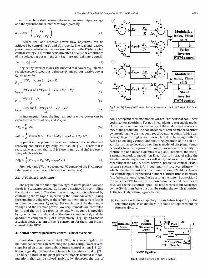
From (6a) and (7), the decoupled PQ control of the PI compen-ated series converter will be as shown in Fig. 2(a).
.2. UPFC shunt branch control
The regulation of shunt input voltage, reactive power flow andhe dc link capacitor voltage, Vdc support is achieved by controllinghe shunt current, Is. The shunt current regulation is achieved byontrolling the voltage E, injected by the shunt converter. Takinghe shunt input voltage V1 as the reference, the shunt current is splitn to two components: Isd and Isq. The regulation of the shunt inputoltage and the reactive power flow requirements are controlledy Isq and the dc link capacitor voltage, Vdc support is providedy Isd, which in turn, depend on the direct component Ed and theuadrature component Eq of E, respectively [17]. Fig. 2(b) shows
typical block diagram of the PI controllers for the shunt branchontrol of the UPFC.
. Neural network predictive control: a brief overview
Generalized predictive control (GPC) is a receding-horizonethod that depends on predicting the plant’s output over several
teps based on assumptions about future control actions [18–20].t was originally developed with linear plant predictor models [21].he linear nature of the plant predictor models resulted into for-ulations that can be solved analytically. However, the use of
Fig. 2. (a) PQ decoupled PI control of series converter; and (b) PI control of shuntconverter.
non-linear plant predictor models will require the use of non-linearoptimization algorithms. For non linear plants, a reasonable modelof the plant is required as the quality of the model affects the accu-racy of the prediction. The non linear plants can be modelled eitherby linearizing the plant about a set of operating points (which canbe very large for highly non linear plants) or by using methodsbased on making assumptions about the dynamics of the non lin-ear plant so as to develop a non linear model of the plant. Neuralnetworks have been proved to possess an inherent capability tocapture the non linear dynamics of a plant. Therefore, the use ofa neural network to model non-linear plants instead of using thestandard modelling techniques will surely enhance the predictioncapability of the GPC. A neural network predictive control (NNPC)system is shown in Fig. 3. An input signal r (n) is converted into yr(n)which is fed to the cost function minimization (CFM) block. Tenta-tive control inputs for specified number of future time instants arefirst fed to the neural identifier by setting the switch S at position 2to enable the CFM to use the response from the neural identifier tocalculate the next control input. The best control input calculatedby the CFM is then fed to the plant by setting the switch at position1. The NNPC algorithm is given below:
Fig. 3. Block diagram of the NNPC system.

4 Comp
(
(
(
4
sofioafacptsuiaPamoicocrnco
ocaSbiwnaafea
ftdvtmvtwa
s
584 S. Tiwari et al. / Applied Soft
(ii) Use the previous calculated control input vector and the neuralidentifier to predict the performance of the plant.
iii) Calculate a new control input vector that minimizes the costfunction.
iv) Repeat steps (ii) and (iii) till desired minimization is attained.(v) Provide the first control input from the vector to the plant.vi) Repeat steps (ii)–(v) for each time step.
. Problem statement
Improved transient stability performance of an electric powerystem can be achieved by enhancing the damping of the rotorscillations. Though the power system stabilizers have been usedor many years to add rotor oscillation damping, but this damp-ng has been found to be insufficient, especially for interareascillations under some operating conditions [22,23]. Effectivelternatives are therefore required to further enhance this dampingor an improved system performance. Since the rotor oscillationsre the result of real power mismatch, emphasis is on effectiveontrol of real power P so as to improve the transient stabilityerformance of the system. The unified power flow controller ishe most versatile of all the FACTS devices available for transienttability enhancement. It can perform a wide range of functionsnder different circumstances with its series converter operating
n one of these possible modes: Direct Injection mode, Bus Volt-ge Regulation and Control mode, Impedance Compensation mode,hase Angle Regulation mode, Automatic Power Flow Control modend its shunt converter operating in either Reactive Power Controlode or Automatic Voltage Control mode [1]. Additionally, it also
ffers the possibility of operating the series and shunt convertersndependent of each other, offering standalone series and shuntompensation. The series converter of the UPFC injects a voltagef variable magnitude as well as variable phase and can therefore,ontrol independently both real and reactive power over a broadange unlike other series connected FACTS controllers. Due to theumerous advantages offered by the UPFC, the undertaken workonsiders the system to be equipped with a UPFC instead of anyther series connected FACTS device.
Since the real power is controlled by the quadrature componentf the series injected voltage (6a), there is a need for an effectiveontrol of the quadrature component Vq of the series injected volt-ge for improving the transient behavior of the system [9,13,15].imilarly, the in phase component of the series injected voltage cane controlled to independently regulate the reactive power flow-
ng through the line, if required. Since the primary objective in thisork is to improve the transient stability performance, a neuraletwork predictive controller is suggested in this paper to provide
reference for only the quadrature component, Vq of the series volt-ge to be injected by the UPFC. The real power reference is obtainedrom the steady state power flow requirements. A non-zero refer-nce for the direct component, Vd of the series injected voltage isssumed to be already available to the UPFC.
The shunt converter supports the real power exchange resultingrom the series voltage injection by either supplying or absorbinghe real power as demanded by the series converter at the commonc link. The voltage of the dc link should be maintained at a constantalue for successful operation of the two converters and for this,he real power balance between the two converters needs to be
aintained [1,15]. The shunt converter also provides the necessaryoltage support to the connected bus which further enhances theransient stability performance of the system. In the undertaken
ork, the variation of the voltage across the dc link and the voltaget the connected bus are controlled by using PI controllers.As the transient stability performance of an electric power
ystem already equipped with PSSs that damp out small modal
uting 11 (2011) 4581–4590
oscillations satisfactorily can further be enhanced wheneverrequired by using a UPFC, the work undertaken here employsa UPFC, with its series and shunt converters operating in directvoltage injection mode and automatic voltage control mode respec-tively, for this purpose. The problem for the undertaken work canbe stated as given below.
Problem: Use of neural network predictive control for the seriesbranch of the UPFC to improve the transient stability performanceof a PSS equipped multimachine power system over a wide rangeof operating conditions.
4.1. Test system
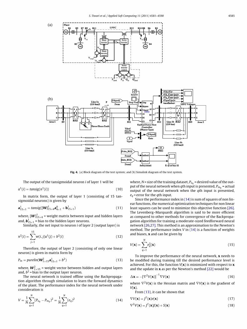
The system [24] used to investigate the transient performanceof a multi-machine system is shown in Fig. 4(a).
The system under consideration is a two area system with powerflowing from Area 1 to Area 2 and was specifically proposed tostudy the low frequency electromechanical oscillations of the largeinterconnected power systems. In spite of the small size of thissystem, its behavior mimics the behavior of the large power sys-tems in actual operation. Each area comprises of two 900 MVAmachines and the two areas are connected by a 220 KV doublecircuit line of length 220 km. The load voltage profile is improvedby installing additional 187 MVAr capacitors in each area. The sys-tem under study is equipped with PSS and has a UPFC installedbetween the bus 11 and bus 12 with bus 11 common to the shuntand series converters and the other side of the series converterconnected to bus 12. The system is modelled and simulated usingMATLAB/SIMULINK. The SIMULINK diagram for the test system isshown in Fig. 4(b).
5. Design of neural plant identifier
The proposed neural network predictive controller employs aneural network for identifying the non linear test system underconsideration. A two layer neural network with sigmoidal hiddenlayer neurons and linear output layer neurons can identify anysystem with any degree of accuracy, subject to the availability ofsufficient number of hidden neurons [25]. The use of sigmoidal hid-den layer neurons enables the neural network to learn the nonlinear and linear relationships between the inputs and outputswhile the use of a linear output neuron ensures an unrestrictedoutput. The neural identifier in Fig. 5(a) that identifies the test sys-tem (including the UPFC) under consideration uses the values ofthe quadrature component of the series injected voltage and theactive output power at two previous instants as inputs to predictthe current value of the active output power. Hence, it is a two-layer feedforward neural network with 4 inputs, a single hiddenlayer with 15 sigmoidal neurons and one linear output neuron. Thedata required for training the network is generated from simulationof the operation of the test system under consideration by applyingVqr restricted within the range +0.1 pu and −0.1 pu (restricting thequadrature component of the series injected voltage to 10% of thenominal line-to-ground voltage) to the plant at regular intervalsof 0.1 s. A section of the random input utilized for this purpose isshown in Fig. 5(b). The neural network is presented with Vq(t − 1),Vq(t − 2), Po(t − 1)and Po(t − 2) as inputs to predict Pm. For linearinput neurons, the output of the input neurons is same as the inputgiven by
a04×1 = [ P0(t − 1) P0(t − 2) Vq(t − 1) Vq(t − 2) ]T (8)
The net input to neuron i in layer 1 (hidden layer) is
n1(i) =4∑
j=1
w(i, j)a0(j) + b1(i) (9)
S. Tiwari et al. / Applied Soft Computing 11 (2011) 4581–4590 4585
; and
a
s
a
wa
n
n
P
wa
toc
V
Fig. 4. (a) Block diagram of the test system
The output of the tansigmoidal neuron i of layer 1 will be
1(i) = tansig(n1(i)) (10)
In matrix form, the output of layer 1 (consisting of 15 tan-igmoidal neurons) is given by
115×1 = tansig([W]1
15×4a04×1 + b1
15×1) (11)
here, [W ]115×4 = weight matrix between input and hidden layers
nd, b115×1 = bias to the hidden layer neurons.
Similarly, the net input to neuron i of layer 2 (output layer) is
2(i) =15∑j=1
w(i, j)a1(j) + b2(i) (12)
Therefore, the output of layer 2 (consisting of only one lineareuron) is given in matrix form by
m = purelin(W21×15a1
15×1 + b2) (13)
here, W21×15 = weight vector between hidden and output layers
nd, b2 = bias to the output layer neuron.The neural network is trained offline using the Backpropaga-
ion algorithm through simulation to learn the forward dynamicsf the plant. The performance index for the neural network underonsideration is
= 1N
N∑q=1
(Poq − Pmq )2 = 1N
N∑q=1
(eq)2 (14)
(b) Simulink diagram of the test system.
where, N = size of the training dataset, Poq = desired value of the out-put of the neural network when qth input is presented, Pmq = actualoutput of the neural network when the qth input is presented,eq = error for the qth input.
Since the performance index in (14) is sum of squares of non lin-ear functions, the numerical optimization techniques for non linearleast squares can be used to minimize this objective function [26].The Levenberg–Marquardt algorithm is said to be more efficientas compared to other methods for convergence of the Backpropa-gation algorithm for training a moderate-sized feedforward neuralnetwork [26,27]. This method is an approximation to the Newton’smethod. The performance index V in (14) is a function of weightsand biases, x and can be given by
V(x) =N∑
q=1
e2q(x) (15)
To improve the performance of the neural network, x needs tobe modified during training till the desired performance level isachieved. For this, the function V(x) is minimized with respect to xand the update in x as per the Newton’s method [22] would be
�x = −[∇2V(x)]−1∇V(x) (16)
where ∇2V(x) is the Hessian matrix and ∇V(x) is the gradient ofV(x).
From (13), it can be shown that
∇V(x) = JT (x)e(x) (17)
∇2V(x) = JT (x)J(x) + S(x) (18)

4586 S. Tiwari et al. / Applied Soft Computing 11 (2011) 4581–4590
Fig. 5. (a) Structure of the neural network identifier; (b) random input to the plant;a
w
J
power, Q in order to damp the rotor oscillations. Since the rotoroscillations are to be damped by controlling the active power P
nd (c) training of the neural network model of the plant.
here J(x) is the Jacobian matrix
(x) =
⎡⎢⎢⎢⎢⎢⎢⎢⎢⎢
∂e1(x)∂x1
∂e1(x)∂x2
· · · ∂e1(x)∂xn
∂e2(x)∂x1
∂e2(x)∂x2
· · · ∂e2(x)∂xn
......
. . ....
⎤⎥⎥⎥⎥⎥⎥⎥⎥⎥
(19)
⎣∂eN(x)
∂x1
∂eN(x)∂x2
· · · ∂eN(x)∂xn
⎦
Fig. 6. Block diagram of the 2-Area system using NNPC.
and
S(x) =N∑
q=1
eq(x) ∇2eq(x) (20)
It is assumed for the Gauss–Newton method that S(x) ≈ 0 [27]and the update (16) becomes
�x = [JT (x)J(x)]−1
JT (x) e(x) (21)
The update in x given by (21) was further modified by adoptingthe trust region approach and the modified method is known asLevenberg–Marquardt method [28]. The update as per this methodis given by
�x = [JT (x)J(x) + � I]−1
JT (x) e(x) (22)
where � is a scalar and I is the identity matrix.The value of � is adaptive in nature and is increased by a factor �
until the change as per (22) results in a reduced performance value.The change is then made to the network and � is decreased by thefactor �. When the value of � is large, this algorithm approaches thesteepest descent method while for small �, the algorithm becomesGauss Newton. Hence, this method shares with the gradient meth-ods their ability to converge from an initial guess which may beoutside the region of convergence of other methods and also hasthe ability of the Gauss Newton method to converge rapidly afterthe vicinity of the converged values has been reached [29].
All the weights and biases for the neural network underconsideration are updated as per (22) during training. TheBackpropagation algorithm employing the Levenberg–Marquardtalgorithm for faster convergence is thus used to train the neuralnetwork as shown in Fig. 5(c) to identify the plant successfully overa range of operating conditions.
6. Neural network predictive control: the algorithm
6.1. Cost function formulation
The proposed neural network predictive controller shown inFig. 6 is based on the receding horizon technique. As the rotorangle oscillations are the result of real power mismatch, this workattempts to control only the real power, P and not the reactive
effectively to the steady state level, the optimization block of Fig. 6minimizes the difference between the actual value of the real power
S. Tiwari et al. / Applied Soft Computing 11 (2011) 4581–4590 4587
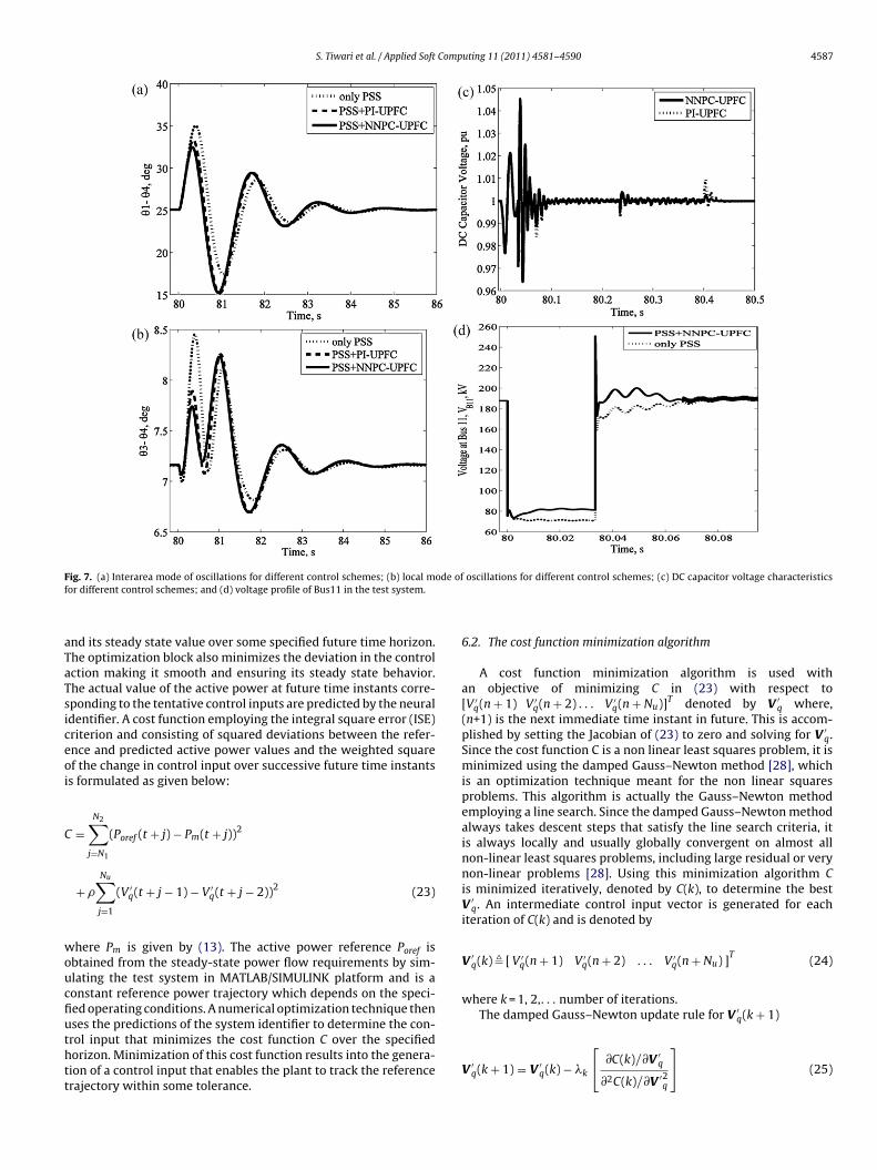
Fig. 7. (a) Interarea mode of oscillations for different control schemes; (b) local mode of oscillations for different control schemes; (c) DC capacitor voltage characteristicsf
aTaTsiceoi
C
woucfiuthtt
or different control schemes; and (d) voltage profile of Bus11 in the test system.
nd its steady state value over some specified future time horizon.he optimization block also minimizes the deviation in the controlction making it smooth and ensuring its steady state behavior.he actual value of the active power at future time instants corre-ponding to the tentative control inputs are predicted by the neuraldentifier. A cost function employing the integral square error (ISE)riterion and consisting of squared deviations between the refer-nce and predicted active power values and the weighted squaref the change in control input over successive future time instantss formulated as given below:
=N2∑
j=N1
(Poref (t + j) − Pm(t + j))2
+ �
Nu∑j=1
(V ′q(t + j − 1) − V ′
q(t + j − 2))2 (23)
here Pm is given by (13). The active power reference Poref isbtained from the steady-state power flow requirements by sim-lating the test system in MATLAB/SIMULINK platform and is aonstant reference power trajectory which depends on the speci-ed operating conditions. A numerical optimization technique thenses the predictions of the system identifier to determine the con-
rol input that minimizes the cost function C over the specifiedorizon. Minimization of this cost function results into the genera-ion of a control input that enables the plant to track the referencerajectory within some tolerance.6.2. The cost function minimization algorithm
A cost function minimization algorithm is used withan objective of minimizing C in (23) with respect to[V ′
q(n + 1) V ′q(n + 2) . . . V ′
q(n + Nu)]T denoted by V ′q where,
(n+1) is the next immediate time instant in future. This is accom-plished by setting the Jacobian of (23) to zero and solving for V ′
q.Since the cost function C is a non linear least squares problem, it isminimized using the damped Gauss–Newton method [28], whichis an optimization technique meant for the non linear squaresproblems. This algorithm is actually the Gauss–Newton methodemploying a line search. Since the damped Gauss–Newton methodalways takes descent steps that satisfy the line search criteria, itis always locally and usually globally convergent on almost allnon-linear least squares problems, including large residual or verynon-linear problems [28]. Using this minimization algorithm Cis minimized iteratively, denoted by C(k), to determine the bestV ′
q. An intermediate control input vector is generated for eachiteration of C(k) and is denoted by
V ′q(k) � [ V ′
q(n + 1) V ′q(n + 2) . . . V ′
q(n + Nu) ]T
(24)
where k = 1, 2,. . . number of iterations.The damped Gauss–Newton update rule for V ′
q(k + 1)
V ′q(k + 1) = V ′
q(k) − �k
[∂C(k)/∂V ′
q
∂2C(k)/∂V ′2q
](25)
4588 S. Tiwari et al. / Applied Soft Computing 11 (2011) 4581–4590
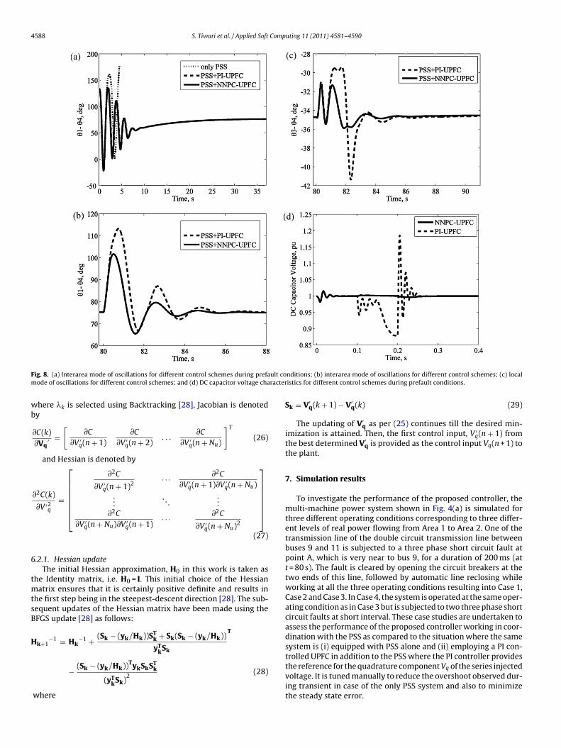
F ult com racter
wb
6
tmtsB
H
ig. 8. (a) Interarea mode of oscillations for different control schemes during prefaode of oscillations for different control schemes; and (d) DC capacitor voltage cha
here �k is selected using Backtracking [28], Jacobian is denotedy
∂C(k)∂Vq
′ =[
∂C
∂V ′q(n + 1)
∂C
∂V ′q(n + 2)
. . .∂C
∂V ′q(n + Nu)
]T
(26)
and Hessian is denoted by
∂2C(k)
∂V ′2q
=
⎡⎢⎢⎢⎢⎢⎣
∂2C
∂V ′q(n + 1)2
· · · ∂2C
∂V ′q(n + 1)∂V ′
q(n + Nu)...
. . ....
∂2C
∂V ′q(n + Nu)∂V ′
q(n + 1)· · · ∂2C
∂V ′q(n + Nu)2
⎤⎥⎥⎥⎥⎥⎦
(27)
.2.1. Hessian updateThe initial Hessian approximation, H0 in this work is taken as
he Identity matrix, i.e. H0 = I. This initial choice of the Hessianatrix ensures that it is certainly positive definite and results in
he first step being in the steepest-descent direction [28]. The sub-equent updates of the Hessian matrix have been made using theFGS update [28] as follows:
k+1−1 = Hk
−1 + (Sk − (yk/Hk))STk + Sk(Sk − (yk/Hk))
yTkSk
T
− (Sk − (yk/Hk))TykSkSTk
(yTkSk)
2(28)
where
nditions; (b) interarea mode of oscillations for different control schemes; (c) localistics for different control schemes during prefault conditions.
Sk = V′q(k + 1) − V′
q(k) (29)
The updating of V′q as per (25) continues till the desired min-
imization is attained. Then, the first control input, V ′q(n + 1) from
the best determined V′q is provided as the control input Vq(n + 1) to
the plant.
7. Simulation results
To investigate the performance of the proposed controller, themulti-machine power system shown in Fig. 4(a) is simulated forthree different operating conditions corresponding to three differ-ent levels of real power flowing from Area 1 to Area 2. One of thetransmission line of the double circuit transmission line betweenbuses 9 and 11 is subjected to a three phase short circuit fault atpoint A, which is very near to bus 9, for a duration of 200 ms (att = 80 s). The fault is cleared by opening the circuit breakers at thetwo ends of this line, followed by automatic line reclosing whileworking at all the three operating conditions resulting into Case 1,Case 2 and Case 3. In Case 4, the system is operated at the same oper-ating condition as in Case 3 but is subjected to two three phase shortcircuit faults at short interval. These case studies are undertaken toassess the performance of the proposed controller working in coor-dination with the PSS as compared to the situation where the samesystem is (i) equipped with PSS alone and (ii) employing a PI con-trolled UPFC in addition to the PSS where the PI controller provides
the reference for the quadrature component Vq of the series injectedvoltage. It is tuned manually to reduce the overshoot observed dur-ing transient in case of the only PSS system and also to minimizethe steady state error.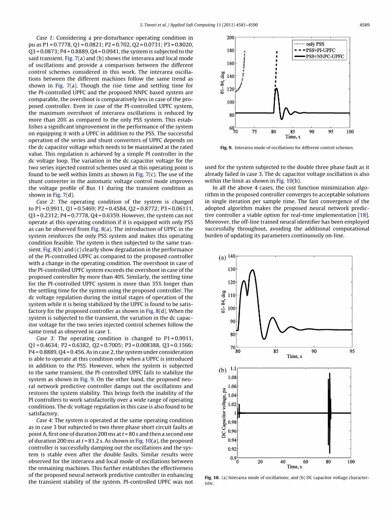
Computing 11 (2011) 4581–4590 4589
pQsoctstcptmlootvdtfsts
tQoascsowtpftdsfsis
QPiitsrrPcs
apoctotot
successfully throughout, avoiding the additional computationalburden of updating its parameters continuously on-line.
S. Tiwari et al. / Applied Soft
Case 1: Considering a pre-disturbance operating condition inu as P1 = 0.7778, Q1 = 0.0821; P2 = 0.702, Q2 = 0.0731; P3 = 0.8020,3 = 0.0873; P4 = 0.8889, Q4 = 0.0941, the system is subjected to the
aid transient. Fig. 7(a) and (b) shows the interarea and local modef oscillations and provide a comparison between the differentontrol schemes considered in this work. The interarea oscilla-ions between the different machines follow the same trend ashown in Fig. 7(a). Though the rise time and settling time forhe PI-controlled UPFC and the proposed NNPC based system areomparable, the overshoot is comparatively less in case of the pro-osed controller. Even in case of the PI-controlled UPFC system,he maximum overshoot of interarea oscillations is reduced by
ore than 20% as compared to the only PSS system. This estab-ishes a significant improvement in the performance of the systemn equipping it with a UPFC in addition to the PSS. The successfulperation of the series and shunt converters of UPFC depends onhe dc capacitor voltage which needs to be maintained at the ratedalue. This regulation is achieved by a simple PI controller in thec voltage loop. The variation in the dc capacitor voltage for thewo series injected control schemes used at this operating point isound to be well within limits as shown in Fig. 7(c). The use of thehunt converter in the automatic voltage control mode improveshe voltage profile of Bus 11 during the transient condition ashown in Fig. 7(d).
Case 2: The operating condition of the system is changedo P1 = 0.9911, Q1 = 0.5469; P2 = 0.4584, Q2 = 0.8772; P3 = 0.06111,3 = 0.2312; P4 = 0.7778, Q4 = 0.6359. However, the system can notperate at this operating condition if it is equipped with only PSSs can be observed from Fig. 8(a). The introduction of UPFC in theystem reinforces the only PSS system and makes this operatingondition feasible. The system is then subjected to the same tran-ient. Fig. 8(b) and (c) clearly show degradation in the performancef the PI-controlled UPFC as compared to the proposed controllerith a change in the operating condition. The overshoot in case of
he PI-controlled UPFC system exceeds the overshoot in case of theroposed controller by more than 40%. Similarly, the settling timeor the PI-controlled UPFC system is more than 35% longer thanhe settling time for the system using the proposed controller. Thec voltage regulation during the initial stages of operation of theystem while it is being stabilized by the UPFC is found to be satis-actory for the proposed controller as shown in Fig. 8(d). When theystem is subjected to the transient, the variation in the dc capac-tor voltage for the two series injected control schemes follow theame trend as observed in case 1.
Case 3: The operating condition is changed to P1 = 0.9911,1 = 0.4634; P2 = 0.6382, Q2 = 0.7005; P3 = 0.008388, Q3 = 0.1566;4 = 0.8889, Q4 = 0.456. As in case 2, the system under considerations able to operate at this condition only when a UPFC is introducedn addition to the PSS. However, when the system is subjectedo the same transient, the PI-controlled UPFC fails to stabilize theystem as shown in Fig. 9. On the other hand, the proposed neu-al network predictive controller damps out the oscillations andestores the system stability. This brings forth the inability of theI controllers to work satisfactorily over a wide range of operatingonditions. The dc voltage regulation in this case is also found to beatisfactory.
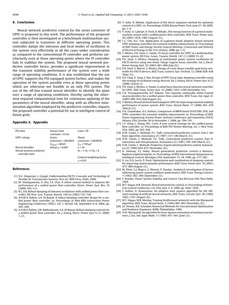
Case 4: The system is operated at the same operating conditions in case 3 but subjected to two three phase short circuit faults atoint A, first one of duration 200 ms at t = 80 s and then a second onef duration 200 ms at t = 81.2 s. As shown in Fig. 10(a), the proposedontroller is successfully damping out the oscillations and the sys-em is stable even after the double faults. Similar results were
bserved for the interarea and local mode of oscillations betweenhe remaining machines. This further establishes the effectivenessf the proposed neural network predictive controller in enhancinghe transient stability of the system. PI-controlled UPFC was notFig. 9. Interarea mode of oscillations for different control schemes.
used for the system subjected to the double three phase fault as italready failed in case 3. The dc capacitor voltage oscillation is alsowithin the limit as shown in Fig. 10(b).
In all the above 4 cases, the cost function minimization algo-rithm in the proposed controller converges to acceptable solutionsin single iteration per sample time. The fast convergence of theadopted algorithm makes the proposed neural network predic-tive controller a viable option for real-time implementation [18].Moreover, the off-line trained neural identifier has been employed
Fig. 10. (a) Interarea mode of oscillations; and (b) DC capacitor voltage character-istic.
4 Comp
8
Uctctaifdtroowuowpmtf
A
R
[
[
[
[
[
[
[
[
[
[
[
[
[
[
[
[
[
[
590 S. Tiwari et al. / Applied Soft
. Conclusion
Neural network predictive control for the series converter ofPFC is proposed in this work. The performance of the proposedontroller is then investigated in a benchmark multimachine sys-em subjected to transients at different operating points. Thisontroller damps the interarea and local modes of oscillation inhe system very effectively in all the cases under considerations compared to the conventional PI controller and performs sat-sfactorily even at those operating points where the PI controllerails to stabilize the system. The proposed neural network pre-ictive controller hence, provides a significant improvement inhe transient stability performance of the system over a wideange of operating conditions. It is also established that the usef UPFC supports the PSS equipped system further, and makes theperation of the system possible even at those operating pointshich are otherwise not feasible in an only PSS system. These of the off-line trained neural identifier to identify the plantver a range of operating conditions, thereby saving the other-ise required computational time for continuous updating of thearameters of the neural identifier, along with an effective mini-ization algorithm employed by the predictive controller, imparts
he proposed controller a potential for use in intelligent control ofuture grids.
ppendix A. Appendix
PSS data Sensor timeconstant = 15 ms
Gain = 30
UPFC ratings Seriesconverter = 160 MVA
Shuntconverter = 160 MVA
Vdcbase = 40 kV Cdc = 750 �FNeural identifier Initial � = 0.001 � = 10Neural network predictive
controller dataN1 = 1 N2 = 5 Nu = 2
Control weighting factor,� = 0.01
eferences
[1] N.G. Hingorani, L. Gyugyi, Understanding FACTS: Concepts and Technology ofFlexible AC Transmission Systems, first ed., IEEE Press, Delhi, 2000.
[2] M. Vilathgamuwa, X. Zhu, S.S. Choi, A robust control method to improve theperformance of a unified power flow controller, Electr. Power Syst. Res. 55(2000) 103–111.
[3] B.C. Pal, Robust damping of interarea oscillations with unified power flow con-troller, IEE Proc. Gen. Transm. Distrib. 149 (6) (2002) 733–738.
[4] A.H.M.A. Rahim, S.A. Al-Baiyat, A robust damping controller design for a uni-fied power flow controller, in: Proceedings of 39th IEEE Universities Power
Engineering Conference (UPEC), vol. 1, Bristol, UK, September 6–8, 2004, pp.265–269.[5] A.H.M.A. Rahim, J.M. Bakhashwain, S.A. Al-Baiyat, Robust damping controls fora unified power flow controller, Int. J. Emerg. Electr. Power Syst. 6 (2) (2006)1–21.
[
[
uting 11 (2011) 4581–4590
[6] V. Azbe, R. Mihalic, Application of the direct Lyapunov method for optimumcontrol of a UPFC, in: Proceedings of IEEE Russia Power Tech, June 27–30, 2005,pp. 1–6.
[7] V. Azbe, U. Gabrijel, D. Povh, R. Mihalic, The energy function of a general multi-machine system with a unified power flow controller, IEEE Trans. Power Syst.20 (2005) 1478–1485 (August (3)).
[8] C.C. Chu, H.C. Tsai, Application of Lyapunov-based adaptive neural networkUPFC damping controllers for transient stability enhancement, in: Proceedingsof IEEE Power and Energy Society General Meeting—Conversion and Deliveryof Electrical Energy in the 21st century, 2008, pp. 1–6.
[9] S. Mishra, P.K. Dash, G. Panda, TS-fuzzy controller for UPFC in a multimachinepower system, IEE Proc. Gener. Transm. Distrib. 147 (1) (2000) 15–22.
10] P.K. Dash, S. Mishra, Damping of multimodal power system oscillations byFACTS devices using non-linear Takagi–Sugeno fuzzy controller, Int. J. Electr.Power Energy Syst. 25 (2003) 481–490 (July (6)).
11] P.K. Dash, S. Morris, S. Mishra, Design of a non-linear variable-gain fuzzy con-troller for FACTS devices, IEEE Trans. Control. Syst. Technol. 12 (2004) 428–438(May (3)).
12] D.Z. Fang, X. Yang, S. Bao, Design of UPFC fuzzy-logic damping controller usingthe strategy of oscillation energy descent, Int. J. Emerg. Electr. Power Syst. 6 (2)(2006) (Article 3).
13] P.K. Dash, S. Mishra, G. Panda, A radial basis function neural network controllerfor UPFC, IEEE Trans. Power Syst. 15 (2000) 1293–1299 (November (4)).
14] G.K. Venyagamoorthy, R.P. Kalyani, Two separate continually online-trainedneurocontrollers for a unified power flow controller, IEEE Trans. Ind. Appl. 41(2005) 906–916 (July/August (4)).
15] S. Mishra, Neural network based adaptive UPFC for improving transient stabilityperformance of power system, IEEE Trans, Neural Netw. 17 (2006) 461–470(March (2)).
16] V.K. Chandrakar, A.G. Kothari, Comparison of RBFN based STATCOM, SSSC andUPFC controllers for transient stability improvement, in: Proceedings of IEEEPower Engineering Society Power Systems Conference and Exposition (PSCE)Atlanta, USA, October 29 to November 1, 2006, pp. 784–791.
17] L.Y. Dong, L. Zhang, M.L. Crow, A new control strategy for the unified powerflow controller, in: Proceedings of IEEE PES Winter Meeting, vol. 1, New York,USA, 2002, pp. 562–566.
18] D.W. Clarke, C. Mohtadi, P.C. Tuffs, Generalized predictive control—Part I: thebasic algorithm, Automatica 23 (1987) 137–148 (March (2)).
19] D.W. Clarke, C. Mohtadi, P.C. Tuffs, Generalized predictive control—Part II:extensions and interpretations, Automatica 23 (1987) 149–160 (March (2)).
20] D.W. Clarke, C. Mohtadi, Properties of generalized predictive control, Automat-ica 25 (1989) 859–875 (November (6)).
21] D. Soloway, P.J. Haley, Neural generalized predictive control—a Newton–Raphson implementation, in: Proceedings of IEEE International Symposium onIntelligent Control, Michigan, USA, September 15–18, 1996, pp. 277–282.
22] X. Lei, E.N. Lerch, D. Povh, Optimization and coordination of damping controlsfor improving system dynamic performance, IEEE Trans. Power Syst. 16 (2001)473–480 (August (3)).
23] M. Klein, G.J. Rogers, S. Moorty, P. Kundur, Analytical investigation of factorsinfluencing power system stabilizer performance, IEEE Trans. Energy Convers.7 (1992) 382–390 (September (3)).
24] P. Kundur, Power System Stability and Control, Tata McGraw-Hill, New Delhi,1994.
25] M.T. Hagan, H.B. Demuth, Neural networks for control, in: Proceedings of Amer-ican Control Conference, CA, USA, June 2–4, 1999, pp. 1642–1656.
26] S. Kollias, D. Anastassiou, An adaptive least squares algorithm for the effi-cient training of artificial neural networks, IEEE Trans. Circuits Syst. 36 (1989)1092–1101 (August (8)).
27] M.T. Hagan, M.B. Menhaj, Training feedforward networks with the Marquardt
algorithm, IEEE Trans. Neural Netw. 5 (1994) 989–993 (November (6)).28] J.E. Dennis, R.B. Schnabel, Numerical Methods for Unconstrained Optimizationand Nonlinear Equations, SIAM, Philadelphia, 1996.
29] D.W. Marquardt, An algorithm for least-squares estimation of nonlinear param-eters, J. Soc. Ind. Appl. Math. 11 (1963) 431–441 (June (2)).