An approach to PSS design for transient stability improvement through supplementary damping of the...
10
954 IEEE Transactions on Power Systems, Vol. 8, No. 3, August 1993 An Approach to PSS Design for Transient Stability Improvement through Supplementary Damping of the Common Low-Frequency R. GRONDIN, (U) I. KAMWA, (M) L. SOULIERES, (M) J. POTVIN, (M) R. CHAMPAGNE, (M) Hydro-Qukbec,IREQ C.P. 1000, Varennes, Qukbec, Canada, J3X IS1 ABSTRACT - The present paper proposes an uncommon struc- ture for the PSS transfer function to improve the dampin of the system low-frequency (in the range of .02-.08Hz), as welfas the usual local and inter-area frequencies (in the ran e of 0.2-2.5Hz). These somewhat conflicting goals are achievecf by adding the speed-based stabilizingsignals of two compensation filters, which independently provide the phase adjustment necessary for ade- uate dampin torques at two widely separated center frequencies 8.e. 0.05 and lflz). Modellingof the open-loop system via the Prony analysis of the multi-machine pulse response, followed by a root-locus study allowed us to determine analytically the supple- mentary damping provided by the new PSS in the two frequency ran es of interest. Simulations of large disturbances on a realistic Hy84u6bec transmission network with more than 59 machines modelled in detail, confirmed that on a fast responding h dro-plant with si nificant Installed capacity, the new PSS can axd consid- erable jamping to the W m i n system oscillation,without any direct supplementary control of the governor. I. Introduction Since its introduction in the early 1960s by many utilities [ll, the PSS has progressively become the basic means to enhance the overall system stability [2]. The device is com- parativelycheap and can maintain a good performancein a wide range of operating conditions. Even if the original goal of the PSS was to mitigate undamped power oscillations limiting the steady-state transfer capability[31[4], a better compromise between its gains at local and inter-area modes can also improve transient stability when the frequency deviations are not too large [2][51. As a matter of fact, much work has been done in the area of PSS tuning for multimachinepower systems, using output feedback,with centralized [6] or decentralized dynamic pole placement [71[8]. Furthermore, multivariable frequency designs using inverseNyquist array [9] or sequential allocation [ 101 have been recently experimented.However,these methods aim at improving the damping of local and inter-area modes only, the common low-frequency swing (below 0.1Hz) being essentially ignored during the tuning process [30]. In effect, starting with the acclaimed paper of de Mello- Concordia which proposed a design procedure based on the damping torque concept [U] , the common practice has been to use the following generic transfer function as the basic structure for a speed-sensitive PSS: sTw (1 + sT,) (1 + sT3) 1 + sTw (1 + sTJ (1 + sTJ PSS(S) =K- FILT(s) The basic dynamic compensator thus includes, in addition to the lead-lag network, a so-called wash-out circuit and a torsional or transducer filter [4]. 92 SM 489-5 PWRS by the IEEE Power System Engineering Committee of the IEEE Power Engineering Society for presentation at the IEEE/PES 1992 Summer Meeting, Seattle, WA, July 12-16, 1992. Manuscript submitted January 16, 1992; made available for printing May 13, 1992. A paper recommended and approved Hydro-Qdbec, Direction Planification Place Dupuis, Montrkal, Qudbec, Canada The ideal stabilizing signal should be in phase with the deviation of the generator speed from the average speed of the entire system. Therefore, the washout effect consists of making the net input to the lead-lag network approximatelyequal to the difference between the instantaneous (mi) and "mean" speeds. This is obtained by filtering the transducer output mi through an equivalent time constant T, which is properly approximated by the generator equivalent inertia (H) [ll: wi sTw Ao(s) = 0; -- = - l+sT, l+sTwO' By modulating the voltage regulator reference with the stabilizing signal V,,(s)=PSS(s)Ao(s), it is possible to generate an electrical torque component which adds damping to all natural frequencies for which V,, and Aw are approximately in phase. Therefore, we can already suspect that a design which ignores the phase adjustment between both signals at some frequency (e.g. 0.05H.z) could fail to add positive damping to the corresponding mode. By studying an actual case from the Hydro-Qu6bec network, we will demonstrate in this paper that this is indeed the case. As a matter of fact,a destabilizingaction of the conventional PSS on the common low frequency tends to reduce the natural stability of the overall system during perturbations involving large frequency offsets. During the early days of the interconnection across Utah and Arizona between the Northwest and Southwest power systems,low frequencyoscillationsat 6c/min were the limiting factor.1twasthenproposedtoadddamping tothismodethrough a supplementary governorcontrol at a large hydrogenerator unit 1121. The control was effective,but the hard-working governor oil pumps developed serious overheating problems due to prolonged operation. Another supplementary governor control was later designed independently in Moussa and Yu [13]. Generally speaking, an improvement of the transient stability through direct action on mechanical parts, such as in fast- valving [14], has received until now limited interest, but this approach should not be entirely ruled out, since it can be effective for damping the lowest mechanical mode when successfully implemented. Using a novel compensator structure which is totally dif- ferent from (l), we claim that, while keeping the essential features of the conventional PSS, it is possible to add positive damping to the lowest natural frequency, which adversely affects the stability of interconnected power systems during large frequency excursions. The basic idea which should be further developedin the third section of the paper is to separate the frequency spectra in two uncoupled bands: the low (0.02-0.08Hz) and hi$h (0.2-2.5%) frequency bands. We first conduct a distinct design for each band, then superpose the two resulting compensatorsand finally obtain a combined PSS with an adequate phase characteristic for low, inter-area and local modes. A such constraining design criteria is practically impossible to fulfill using the usual de Mello-Concordia structure,which specifically applies to damping of the so-called 0885-8950/93$03.00 0 1992 IEEE __
Transcript of An approach to PSS design for transient stability improvement through supplementary damping of the...

954 IEEE Transactions on Power Systems, Vol. 8, No. 3, August 1993
An Approach to PSS Design for Transient Stability Improvement through Supplementary Damping of the Common Low-Frequency
R. GRONDIN, (U) I . KAMWA, (M) L. SOULIERES, (M) J. POTVIN, (M) R. CHAMPAGNE, (M)
Hydro-Qukbec, IREQ C.P. 1000, Varennes, Qukbec, Canada, J3X I S 1
ABSTRACT - The present paper proposes an uncommon struc- ture for the PSS transfer function to improve the dampin of the system low-frequency (in the range of .02-.08Hz), as welfas the usual local and inter-area frequencies (in the ran e of 0.2-2.5Hz). These somewhat conflicting goals are achievecf by adding the speed-based stabilizing signals of two compensation filters, which independently provide the phase adjustment necessary for ade-
uate dampin torques at two widely separated center frequencies 8.e. 0.05 and lflz). Modelling of the open-loop system via the Prony analysis of the multi-machine pulse response, followed by a root-locus study allowed us to determine analytically the supple- mentary damping provided by the new PSS in the two frequency ran es of interest. Simulations of large disturbances on a realistic H y 8 4 u 6 b e c transmission network with more than 59 machines modelled in detail, confirmed that on a fast responding h dro-plant with si nificant Installed capacity, the new PSS can axd consid- erable jamping to the Wmin system oscillation, without any direct supplementary control of the governor.
I. Introduction Since its introduction in the early 1960s by many utilities
[l l , the PSS has progressively become the basic means to enhance the overall system stability [2]. The device is com- paratively cheap and can maintain a good performance in a wide range of operating conditions. Even if the original goal of the PSS was to mitigate undamped power oscillations limiting the steady-state transfer capability[31[4], a better compromise between its gains at local and inter-area modes can also improve transient stability when the frequency deviations are not too large [2][51. As a matter of fact, much work has been done in the area of PSS tuning for multimachine power systems, using output feedback, with centralized [6] or decentralized dynamic pole placement [71[8]. Furthermore, multivariable frequency designs using inverse Nyquist array [9] or sequential allocation [ 101 have been recently experimented. However, these methods aim at improving the damping of local and inter-area modes only, the common low-frequency swing (below 0.1Hz) being essentially ignored during the tuning process [30].
In effect, starting with the acclaimed paper of de Mello- Concordia which proposed a design procedure based on the damping torque concept [U] , the common practice has been to use the following generic transfer function as the basic structure for a speed-sensitive PSS:
sTw (1 + sT,) (1 + sT3) 1 + sTw (1 + sTJ (1 + sTJ PSS(S) =K- FILT(s)
The basic dynamic compensator thus includes, in addition to the lead-lag network, a so-called wash-out circuit and a torsional or transducer filter [4].
92 SM 489-5 PWRS by the IEEE Power System Engineering Committee of the IEEE Power Engineering Society for presentation at the IEEE/PES 1992 Summer Meeting, Seattle, WA, July 12-16, 1992. Manuscript submitted January 16, 1992; made available for printing May 13, 1992.
A paper recommended and approved
Hydro-Qdbec, Direction Planification Place Dupuis, Montrkal, Qudbec, Canada
The ideal stabilizing signal should be in phase with the deviation of the generator speed from the average speed of the entire system. Therefore, the washout effect consists of making the net input to the lead-lag network approximately equal to the difference between the instantaneous (mi) and "mean" speeds. This is obtained by filtering the transducer output mi through an equivalent time constant T, which is properly approximated by the generator equivalent inertia (H) [ll:
wi sTw Ao(s) = 0; -- = - l+sT, l+sTwO'
By modulating the voltage regulator reference with the stabilizing signal V,,(s)=PSS(s)Ao(s), it is possible to generate an electrical torque component which adds damping to all natural frequencies for which V,, and Aw are approximately in phase. Therefore, we can already suspect that a design which ignores the phase adjustment between both signals at some frequency (e.g. 0.05H.z) could fail to add positive damping to the corresponding mode. By studying an actual case from the Hydro-Qu6bec network, we will demonstrate in this paper that this is indeed the case. As a matter of fact, a destabilizing action of the conventional PSS on the common low frequency tends to reduce the natural stability of the overall system during perturbations involving large frequency offsets.
During the early days of the interconnection across Utah and Arizona between the Northwest and Southwest power systems, low frequency oscillations at 6c/min were the limiting factor.1twasthenproposedtoadddamping tothismodethrough a supplementary governor control at a large hydrogenerator unit 1121. The control was effective, but the hard-working governor oil pumps developed serious overheating problems due to prolonged operation. Another supplementary governor control was later designed independently in Moussa and Yu [13]. Generally speaking, an improvement of the transient stability through direct action on mechanical parts, such as in fast- valving [14], has received until now limited interest, but this approach should not be entirely ruled out, since it can be effective for damping the lowest mechanical mode when successfully implemented.
Using a novel compensator structure which is totally dif- ferent from (l), we claim that, while keeping the essential features of the conventional PSS, it is possible to add positive damping to the lowest natural frequency, which adversely affects the stability of interconnected power systems during large frequency excursions. The basic idea which should be further developed in the third section of the paper is to separate the frequency spectra in two uncoupled bands: the low (0.02-0.08Hz) and hi$h (0.2-2.5%) frequency bands. We first conduct a distinct design for each band, then superpose the two resulting compensators and finally obtain a combined PSS with an adequate phase characteristic for low, inter-area and local modes. A such constraining design criteria is practically impossible to fulfill using the usual de Mello-Concordia structure, which specifically applies to damping of the so-called
0885-8950/93$03.00 0 1992 IEEE __

955
"high frequency" hunting modes (0.2-2.5Hz) [30]. Such a structure, namedstabilizer universd tranrferfmction, is further described in reference [ 131 (p.84).
In order to design the new compensator, we will fmt construct the models of the open-loop system. Our approach does not rely on the common damping torque concept and associated power-voltage characteristics [3][11]. Instead, we use pulse testing in a transient stability program (TSP) followed by Bony analysis of the speed responses, to derive transfer functions of the entire multi-machine system as seen from the voltagere~rset-point,pri~toPSS installation. Thischoice is motivated by the successN results obtained by other designers of power system controllers using TSP outputs as test signals [15][16]. Section III illustrates the basic difference between conventional and novel PSSs using the root-locus analysis. It appears that, at all gain values, the latter add positive damping, while the former add negative damping to the 0.05Hz mode. In section IV, simulations of large disturbances con- finned this argument, with the new PSS outperforming the conventional one in the most difficult cases. Section V briefly discusses implementation aspects.
I I
I 1 1 I 1 1 1 I I I I I I
1
I
Figure 1. A Multimachine Power System,
II. Open-Loop Modelling - We assume for the sake of convenience that there are n
synchronous machines to be equipped with PSS. For our purpose, the modelling includes satmation and damper effects [U]. The other generators involved in the large-scale power system are represented by a constant voltage source behind a transient impedance, and then incorporated in the overall interconnecting network (Fig. 1). Each plant involves two set-points, at which a control signal can be added to achieve a supplementary damping of controllable and locally observable system modes. The first is the mechanical power reference, whose modulation with a signal proportional to system fie- quency can mitigate system oscillations in the range of c/min. We shall not consider this option any further, since it pmeeds through a governor path involving sensitive and hardworking
mechanical parts which, in the long run, can mult in consid- erable fatigue. The second modulable set-point is the voltage regulator reference. Here, damping is effected through the PSS by producing p e r t d o n s in electrical torque on the ith machine (APA in phase with perturbations in rotor speed (ai). This insightful justification of the PSS action gives rise to the damping torque concept. But, as rightly pointed out by Krause in his discussion of [21], this notion is not actually necessary for a successful PSS design.
As is usual in control theory, the starting point for deriving a solution to this problem is a valid model of the linearized system behaviour. The most obvious one is depicted in Fig. 2. Such a model assumes that the whole system can be organized in n interacting subsystems each involving one forced input (AV&), one measurable output (Aoi) and one disturbance input to account for the n-1 coupling functions relating the ith plant to the others, Obviously, this model, which is similar to models in [8][101[15], does not make any distinction between normal and damping torques. This allows for a more general and flexible approach to the PSS design [8][10]. The set of nxn hansfer functions involved in the system description can be combined in a single matrix of fractions involving the various inputatput relationships:
I

956
Table 1. Transfer functions as seen h m LG2 for a twical load-flow condition (1988 Transmission Network). .- I G 11 (s) (LG2- to-LG2) I G,,(s) (LG2-to-LG3) I G13(S) (LG2-to-LG4)
LG4 5, 1 4 , I 4 , LG3 LG2
h
E a 2
-lo' 0 ; IO 1; :o
h
5 a '1,
-" 0 5 10 15 20
sec sec sec
Figure 3. Graphical Validation of Systems Transfer Functions as Seen from LG2 AVR set-point Model; o Actual data).
In order to gain insight about the dynamics of the system low frequency mode, identification experiments were con- ducted on a now obsolete Hydro-Quebec network (year 1988), using the ST600 [25] software (which is the most often used TSP in our compan ). More specifically, we considered the realistic problem of Aignin modem stabilizers for retrofittin those installed in three largeaydro plants (LG2, LG3 and LG47 located in the north of the country. To identify the 3x3=9 transfer functions involved in the model (2), the LG2, LG3 and LG4 generators were first simulated in open-loop, by removing the conventional PSS initially present. A step perturbation (.003p,u.) was then a lied in turn at the voltage regulator
mt of LG2, LG3YG4, and the resulung speed deviaoons z t g t h r e e plants recorded for each experiment. p?fterwards. the response signals were analyzed using a customized Prony analysis software [28]. At this stage, we found that in all but one case, the low frquency damping was poorly identified, becauseProny analysis tends to favor high frequencies (>o. 1Hz) over low frequencies, when core memory limitation shortens the observation window. We then de-sampled (or decimated) the raw data to enhance the 0.05H.z component, but the Prony estimates still not produced satisfacto predictions of this fr uency dynamic. Therefore, we ?mall relied on a nainear-least squares software to im rove tie transfer func- tions, initially identified using the meti!od described in [28].
As shown in Fig.3, the resultin open-loop models represent the low frequenc dynamic withaigh accurac at least from $e stand int or step response oodness~f-f!~. Table 1 also &plays E first column of the &s) mamx corresponhng to this set-up. To facilitate mode recognition and interpretatton, results are ex ressed in terms of the pulse response com mverseLap&e transform of Gi,(s)), accordmg to the foE%!
!ormula: k =m
hij(t) = C e x p ( - q t ) {uk cos(2xf,t) + bk sin(2xf,t)} (3)
where m is the number of distinct modes of G,{s). The damping ratio, conventionally defined as t; = ok/2xf, [24], is clearly unsatisfactory for all oscillating modes. For instance, a control scheme is needed for LG2, to increase the damping ratios of modes 0.042Hz, 0.623Hz and 1.387Hz from their actual level
k = l
to a value ordinarily greater than 0.1. It is also interesting to observe that, due to the governor loop, the much damped natural mode corresponds to the common low-frequency swing, and to some extent this could explain why the system planner is usually more concerned with the local (1.387Hz) and inter-area (0.623H.z) mode issues. Nevertheless, time-domain simulations will subsequently show that adding more damping to this low frequency mode of oscillation (0.042H.z) will significantly improve the systems overall stability.
III. Root-Locus Analysis After an extensive number of time-domain simulations and
analytical studies comparing the performances of the conven- tional PSS structure under various sets of parameter values, it became impossible to produce the necessary phase lead at 1% without excessive lead at 0.05Hz. During the process, the necessity of using two decoupled compensating filters to achieve these two conflicting goals became more and more obvious. Through trial and error, we found that the structure displayed in Fig. 4(a) was appropriate for this matter. As for comparisons, we have used the conventional PSS model actually installed at LG2. However, this device is sensitive to electrical (or acceleration) power instead of speed, and a slight alteration was necessary to make it behave like a @-based PSS. The most straightforward one consists in cascading the power-sensitive PSS with a derivative circuit including a gain of 2H. Obviously, the resulting equivalent PSS appearing in Fig. 4(b) is closely related to the "universal" PSS of (1). Typical settings for both structures, which are actually appropmte for LG2, are given in Table 2.
Table 2. PSS Settings for LG2 Generating Unit.
Kbl 8.0 Thl 0.1719 Th7 0.1980 Tmp 0.0200 Kb 10.00 Tbl 0.10 Th2 0.1980 Th8 0.3145 Tmw 0.0200 Kh 35.00 Tb2 4.0 Th3 0.1719 Th9 0.3740 Tpl 0.0100 K(New) 1.00 Tb3 4.0 Th4 0.1980 ThlO 0.3145 Tp2 0.6600 K(0ld) 44.50 Khl 39.0 Th5 0.1002 T h l l 0.1000 Tp3 2.0000 H 4.00 Kh2 39.0 Th6 0.0589 Th12 0.0600

957
- a- s(l+ S-Ibl)
Kbl (1 + sl'b2)(1+ sl'b3)
> 1 ' -- (1 + sl'mw)
+ (I +sThlXl +dlX3Xl +sTh5) + &A- *;
Khl (1 + sThZXl+ sTh4)(l+ m)
I -
n - *-- (1 + m7)(1+ s'Ih9)(1+ $Il111)
-Kh2 d
b- - > a+ STPU ----*- 1
, (1 + sTmp) - K (1 + sTpZ)(l+ sTp3)
Figure 4. New (a) and Conventional (b) PSS Structure.
10-1 100 10' Hz
. . . . . . . . . . . . . . .
. . . . . .
. . .
. . . . . . . . . . . . . . . . . . . . . . . . . . . . . .
. . . . . .
-9 . . . 0 . . . . . . . . . . . . . . . . . . . . . . . .
, -. . , + . -: - :, . . . . .
10" 10-1 100 10' Hz
Figure 5. Individual Frequency Response of the New Structure Components:
- Low- and --- High-pass filters; o Combined filters
Figure 6. Comparative Frequency Response of Several PSSs: - New, --Conventional (Fig. 4b) and -.-.-Universal (eq. 1) PSS;
(0) New PSS High-Pass Filter
To highlight the decoupled behaviour of the two parallel filters constituting the new structure in Fig. 4(a), @e @equenc responses of each component have been plotted in Figm 5 . 6 is interesting to note from these curves that the new PSS high-pass component, constructed as a differential filter, is nearly similar in terms of gain and phase above 0.1Hz to the conventional PSS. Both compensators.pmwde adequap phase lead between 0.4Hz and 2Hz, but they introduce excessive lead
at frequencies below 0.2 Hz. Fortunatel , Fig. 5 demonstrates that a combination of the high- d low-pass frequency responsesintoasinglestructllreresultsinsatisfac~behaviour for all frequencies, from .OlHz to 2Hz. We also find from Fig. 6 that the new 2-stage PSS (Fig. 4a) discloses only a 10" phase leadat O.O5Hz, wh- the conventional one ig. 4b) provides 140" at the same cntlca frequency (t.e., mu$& 7 times more lead).
958
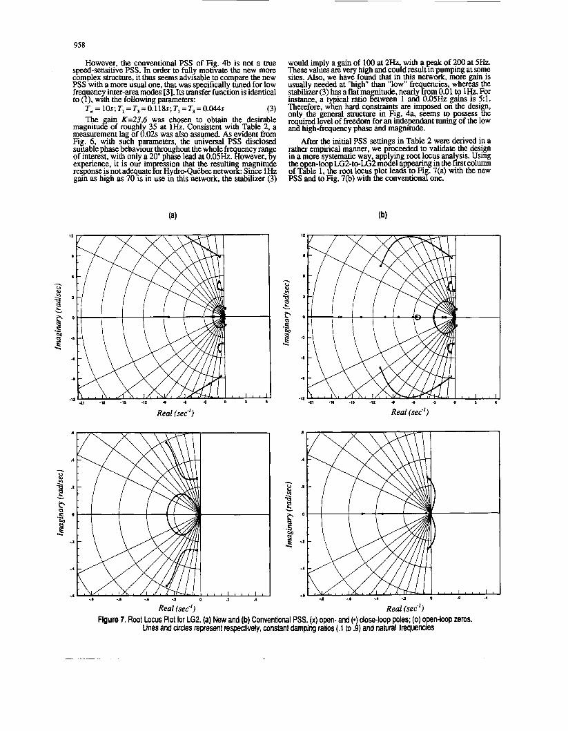
However, the conventional PSS of Fig. 4b is not a true speed-sensitive PSS. In order to fully mouvate the new more complex structure, it thus seems advisable to compare the new PSS with a more usual one, that was specifically tuned for low fr uency inter-area mpdes [3]. Its transfer function is identical to?). with the followmg parameters:
T,= ~ O S ; T , = T , = O . ~ ~ ~ S ; T , = T , = O . O ~ ~ S (3) n e ain K=23.6 was chosen to obtain the desirable
magnitug of rough1 35 at 1Hz. Consistent with Table 2, a measurement lag of d.02~ was also assumed. As evident from Fig. 6, with such parameters, the universal PSS disclosed suitable phase behaviour throughout the whole fr uency ran e of interest, with only a 20" phase lead at O.OS~?Iowever, l y expenence, it is our im ression that the resultln magnitude response is not adquateFor HydmQu~bec networf: since HZ gain as high as 70 is in use in this network, the stabihzer (3)
Real (sec-')
would imply a gain of 100 at 2Hz, with a peak of 200 at 5Hz. These values are very high and could result in pumping at some sites. Also, we have.found that in this network, more gain is us+y needed at "high" "low" fr uencies, whereas the stabdner (3) has a flat maptude, nearl3om 0.01 to 1Hz. For instance, a typical m o tween 1 and 0.05% gains is 5:l. Therefore, when hard consmnts are imposed on the desi only the general structure in Fig. 4% seems to possess g6 r uired level of freedom for an independant tuning of the low ,"a high-frequency phase and magnitude.
After the initial PSS settings in Table 2 were derived in a rather empirical manner, we proceeded to validate the design in a more systematic wa , appl ing root locus anal sis. Using the o n-loo ~ ~ 2 - t o - ~ & m J e ~ appear?ng m the &t column of T%e 1, t!e mot locus lot leads to Fi .7(a) with the new PSS and to Fig. 7(b) with $e convention8 one.
Real (sec")
Real (sec-') Real (sec-') Figure 7. Root Locus Plot for LG2. (a) New and (b) Conventional PSS. (x) open- and (.) close-loop poles; (0) o.pen-loop zeros.
Lines and circles represent respectively, constant damping rafos (.l to .9) and natural frt?quenCleS
~ - -

Comparin both plots, we see that the two desi s provide nearly ual &ping to inter-area and local m z s . Never- theless3e conventional PSS a m negative dam in to the common low frequency (reduced transient stability!, ithough the proposed structure adds positive dampin to @s m g e (increared transient stabili. .). Movver, wid! an increasmg Eain, the convenuod stabXzer will zero the +m in of the
closed-loop low-frequency mode, if the gam is f S increased. As rightly pointed out in [2], transient stability requirements related to the common low-frequenc behaviour are thus the most limitin factors in convenuonal6SS design. A uantitative check of k e overall design is done by lookm at 8 e points marked with a star on Fig. 7, since they cqresponi to closed-loop $1" positions with the actual gatn sevgs. The data in Table render the close-loop informauon in a more usable format. It is easily seen that the low- is 6 times grater in the new design than i%e convention8 one.
Table 3. Closed-Loop Dominant Modes
.05Hz frequency and even lead p a negauve& 8am
uency dampm
0
Novel PSS I Conventional PSS '0 I
I-\
1 1 i 1 1 :
A..: ........ \................; ................. i ...............-
0.042 0.022 0.382 0.635 1.519
0.30 0.012 0.040 1.51 0.352 0.000 0.53 1.003 0.243 0.26 0.811 0.648 0.25 2.350 1.569
L - 0.05
0.65 0.20 0.24
t
IV. Performance Following Large Disturbances Usin a small-signal model, the previous analysis shows
that our %sic design is statisfactory. However, time-domain simulations are necessary to evaluate the overall performance during large disturbances, since nonlinear phenomenaincluding PSS saturation will then significantly affect power system behaviour.
In the first series of simulations, the same network repre- sentation (400 buses, 59generatars,4 SVCs and 7 synchronous condensers) previously involved in the PSS design was used Except for small variations on the high frequency gain, the new PSS seam s in Table 2 were used for all three g e n e m g units (LG2, LGf. LG4) at the La Grande Complex (total genemon: 10,400 MW) with limits set at _+15%. Elsewhere in the system, conventional originally installed PSS were retained. Selected results illustrating the improved performance obtained from the
Slip: Hz & Stabilizing signal: p.u. I I
0.5
0
-0.5 I I I I
0 200 400 600 800 Time (in Cycles)
959
new PSS are shown in Figs. 8 and 9. The results shown are for a contingency involvin a six-cycle three-phase fault on a 735 kV circut in the Jamessa transmission conidor, followed by a lme outage. MOR iicall two cases are compated: the first involves new P F a t LGJ; LG3 and LG4 (closed-loop) whereas the second assumed no PSS on these three units (open loop).
Fig. 8 confirm@ that the PSS just designed substantially enhances the dam mg of the common low- uency oscillation
bilizing signal gene+ by the PSS js rightly in phase with the speed swings. This is the .major intuiuve m y o n why the supplementary ue contnbuted by the PSS is actually a
ingtorqueas natural frequencies. These findings clearly valr&te$ cpnc ts behind the new PSS and b m y confirmed the pmicuonseflawn from root-locus analysis.
However, results comparing more specifically conven- tional and new scenarios are still neces to technicall 'ustify a costly retrofit of the existing ~a GS complex P#. This need motivated a second senes of simulations, using a future Hydm u+ec network currently in the design stage. B-edes three & the re resentauon used includes a&hOnd
s 10) with regard to the 1988 network.
elecmcal power) at all m a p generatmg units. Therparameters were optimized by system planners using routine methods. The alternative case was obtained by remfithn al l existing PSS by new ones. Admittedly, the setungs. were cfosen in a rather ad hoc manner, by kee m the same m e constants as UI Table 2. However, the new PiSiigh (Kh) and low (Kb) frequenc gains at various locations were adjusted to achieve an ovds tab i - lizing effort comparable to the benchmark case. Meanwhile, comparisons were made between the new stabilizer with a high frex~~ency filter only .and the. cpvenuonal PSS, in order to ev uate their respecuve behawour with regard to high fre- quency oscillations. Selected results illustrating the differences between these three scenarios appear in Figures 10 to 11.
It can be initiall observed that the benchmark case involving conventionJPSS is very close to unstable, since the lar e swin comes with 1 damped inter-area oscillations at %.37 anl0.72H.z. *.=&er hand, Fig. 10 shows that the new PSS essenually miugates the Sustamed OSCdlahOnS throu h the su plementary ing of the low-frequency mode. d e case sfown is for the d 2 unit, but results were also irn ressive at theother generating plants. In fact, a c m p i s o n o f s & i a signals in both cases clear1 shows that near the m e t=1358 cycle, the benchmark stabiizing si is in piny opposition with the speed, whereas the new P&&nal remans in phase.
during a relativeg severe perturbation. F 3 ermore, the sta-
h e enerators(15)andSV8 benchmark case invo I ves conventional PSS (sensitive to
-401 I 1 I I 0 200 400 600 800
Time (in Cycles)
Figure 8. LG2 responses to a fault near Abitibi: (J Sped for then open- and (---) closed-loop systems; r) Stabilizing signal (New PSS).
Figure 9. Churchill Falls rotor le relative to LG2 for a fault near AM- Cbi: Open- a--) Cbsed-loop systems.

960
I I I -1.5 I 1 I I I I
0 200 400 600 800 1000 1200 1400 1600 1800 2000
Time (in Cycles)
Conventional and (-.-.-) New PSS. Figure 10. LG2 responses to a fault near Nemiskau: Speed for Conventional and (---) New PSS; (*) Stabilizing signal for
Deviation in (Deg.) 110, I I I
100
90
80
70
I 1 I
0 500 1000 1500 2000
200
100
0
-100
h4w 1 I I
500 1000 1500 2000 0 Time (in Cycles) Time (in Cycles)
Figure 11. Churchill Falls rotor angle relative to Montrhal Region Figure 12. LG2 responses to a fault near Abitibi: Mechanical power for for a fault near Nemiskau: (J Conventional and (---) new PSS; (J Conventional and (---) new PSS;(') New PSS high-frequency filter
(') New PSS with high-frequency filter only. only.
Thus, the first contributes to a supplementary destabilizing low-fquency tor ue, while *e second conqibutes to a strong damping torque. his resuit is not surpming, since it was already predicted by the root-locus analysis.
10 and 11 also &play the results of a situatlo? where only &e high-frequency part of the new PsS was acuve Even in hs -, the stability pe~omance was above the benchmark. This unquestionable superiority could have been already concluded from Fig. 6, since the phase lead of this
compensator at ve low fr uencies is only 90", com wed to the conventional 2s l80"'ead. Therefore, even if Le high
uenc gain and phase characteristics of both filters.are %I jJntical, the differential one has a more appro pansient .stabihv* In the low frequency c o m ~ n ~ m r involved 1n the new Pss (Fig. 4(a)) is responsible for increasing this benefit by further reducing the destabilizing phase lead at
low frequencies-
Besides comparing the conventional new PSS, Fi s. low-&quency phase response* which in turn

96 1
By observing the mecwical curves in Fig. 12 one can derive a heuristic explanahon of the new PSS acuon: when a loss of generauon occurs, the PSS reacts more promptly by increasing production to a satisfactory level in about 600 cycles. By contrast, the conventional PSS reaches the same operating level only after 1200 cycles, during which time the system experiences sustained swings. Interestingly, the results suggest that as long as the common low- uency behaviour is con-
governor control .OF [12]. However, no direct control .of mechanical parts is involved in the present scheme, which constitutes a valuable benefit.
At this poi? it is worth mentioning that-the networks used in our stuhes involve hydro-genemg units at all but a few plants. Thus, it is certainly legitmate to view the goodbehaviour of the new scheme as bvin been achieved with some ease due to thelr fast-respondm cfaracteristics [12]. Moreover, the flexibili of mechanic8 power modulation hardly needed for effectivz counteracting the slow motion of large units, would be possibre only if sufficient spin-off reserve was available on site. Nonetheless, this requirement is not more stringent for the new PSS and this is best understood referring once again to Fig. 12. Here we find that on a long term basis, the system's need for more eneration is equall well recognized by each design, but the P8S that includes a credicated low-frequenc com n- satin stage is the only one which reacts sufficiently &st to Clly comjy with transient stabihty requmments.
cerned, one can com are the new 9 PS with the supplementary
V. Digital Implementation Issues Involving several high-order transfer functions, the new
PSS in Fig. 4 obviously entails uncommon implementation burden. Such a scheme would hardly be achieved using a conventional analog design. However, even more complicated structures than the one proposed could be easily implemented as digital filters. The computer-based approach is especially suitable for realizing differential filters, since these require calculations with high and stable precision to guarantee a satisfactory performance. This choice complies with recent trends of the industry towards the so-called CLpSS (for microprocessor-based PSS) [18][20]. A digital design can achieve a programmable and highly reliable system through high-speed processors and redundancy [29]. Furthermore, such a system typically provides, at no extra-charge, additional desirable features such as self-test and automatic recovery after fault, facilities for commissioning and routine maintenance tests, as well as remote communication to initiate or collect data from stored transient events [U].
Currently, the most complex problem in designing a speed-based PSS (also called Delta-Omega PSS [3]) is that of measuring the shaft speed with few lag and high accuracy. A high-sensitivity analog speed sensor with only a 5-ms time constant was designed at Ontario-Hydro in the early 1960s [l]. Since the device was directly mounted on the shaft, it was sensitive to torsional modes when used on large fossil-fired units. To prevent negative damping contributions by the PSS, heavy filtering was required which invariably introduced an additional phase lag to the input signal. For this reason, it was found that the stabilizer gains needed to be limited at some of the considered locations. It was only possible to overcome these limitations through a new scheme based on a combined mea- surement of electrical power and speed 1171. The resulting so-called Delta-P-Omega PSS [3][27], though having a good performance, actually involved two dedicated analog trans- ducers.
A method readily amenable to digital PSS was derived by de Mello et a1 [U]. Since it relied on voltage and current measurements easily obtained through FT and CT devices already available in the plant, the cost of the tranducer is minimal. Measuring of the speed of rotation of the internal voltage phasor, revealed no torsional filtering problems.
However, as presented in the above paper, the method was somewhat sensitive to experimental factors such as quantizing noise, offset, and phase balance, and seemed to work better under a 12.5-ms sampling period under small slip conditions. According to available literature, it thus seems like the most reliable way to acquire digital samples of speed signals, still is to digitize the output of an analog frequency transducer [U]. However, simulation studies with the TSP have shown that whatever the method used to design a digital speed transducer, the resulting device should be equivalent to a time constant of less than 40 ms in order to cover the most difficult stability cases without any gain adjustment problems. For a safe design, this 40-ms lag should also include the supplementary delays due to computer processing time and the blocking effect inherent to the digital-to-analog converter mandatory at the digital PSS output.
VI. Conclusions This paper described the concepts behind a novel transfer
function structure for power system stabilizers, mainly designed to add positive damping to the common low-frequency mode. By contrast, conventional stabilizers show a destabilizing effect on this mode, due to their excessive phase lead at frequencies near DC. The conflicting goals of providing damping torques at both high (0.2-2H) and low (.01-.08Hz) frequencies are actually achieved using two decoupled filters operating in parallel. Besides retaining the usual features of a normal power system stabilizer such as mitigation of inter-area oscillations and damping of generator local mode, the new design sub- stantially improves transient stability, especially for contin- gencies involving large and sustained frequency excursion.
Small signal analysis is used to illustrate the intriguing behaviour of the proposed scheme and to shed light on the detrimental effect of a conventional design on the damping of low-frequency mode. Large perturbation simulations on two typical configurations of our network broadly confinn the linear analysis and further show that the new PSS is sufficiently robust to remain effective for widely different oscillating patterns. However, as the filters used to achieve adequate deqoupling between the two frequency bands am of the differential type, digital implementation appears to be the best choice, and perhaps the only feasible one. For some time now, we have been developing a prototype digital Delta-Omega stabilizer based on the new transfer function structure, and practical results will be reported in a forthcoming paper [29].
(11
121
131
141
151
161
m
VII. References
P.L. Dandeno, A.N. Karas, K.R. McClymont, W. Watson, "Effectof High Speed Rectifier Excitation Systems on Generator Stability Limits", I€€€ Trans., PAS-87(1), Jan. 1968, pp.190-201.
A. Olwegard, K. Wake, G. Waglund, H. Frank, S. Torseng, 'Improvement of Transmission Capacity by Thyristor Controlled Reactive Power, ibid., PAS-87(8), August 1981, pp.3930-3939.
P. Kundur, M. Klein, .G.J. Rogers, M.S. Zywno, 'Application of Power System Stabilizers for Enhancement of Overall System Stability", /€€E Trans., PWRS-4(2), May 1989, pp.614-626. E.L. Busby, J.D. Hurley, F.W. Kea , C Raczkowski, "Dynamic Stabili Improvement at Monticello itation - Analytical Study and Field xsts', ibid., PAS-98(3), MayIJune 1979, pp.889-901.
E.V. Larsen, D.A. Swann, "Ap I ing Power System Stabilizers. Parts I, II (L Ill", /E€€ Trans., i&-l00(6). June 1981, pp.3017- 3046.
S. Lefekre, 'Tuning of Stabilizers in Multi-Machine Power Sys- tems', rbrd., PAS-102(1), pp.290-299.
C.M. Lim, S. Elan ovan, "Design of Stabilizers in Multimachine Power Systems", /E€ Roc. C, 132(3), 1985, pp.146-153.

962
[8] C.N. Chen, Y.Y. Hsu, "Coordinated Synthesis of Multimachine Power System Stabilizer Using an Efficient Decentralized Modal Control Algorithm', I€€€ Trans., PWRS-2(3). August 1987, pp.543-551.
[9] M.J. Gibbard, 'Coordinated Desi n of Multimachine Power System Stabilisers Based on Dam ing Borque Concepts", I€€ Proc. C, 135(4), July 1988, pp.276-lM.
[lo] F. Crusca M. Aldeen, "Multivariable Fre uency-Domain Tech- niques for' the Systematic Design of Stablizers for Large-scale Power S stems", IEEE Paper 91 WM 273-3 PWRS, Presented at the IEEdPES Winter Meebng, New York, NY, February3-7,1991.
(111 F.P. De Mello, C. Concordia, "Concepts of S nchronous Machine Stability as Affected by Excitabon Control", I,& Trans., PAS-88,
[I21 F.R. Schleif, G.E. Martin, R.R. Angell, "Damping of System Osallationswith a Hydrogenerating Unit", I € € € Trans., PAS-86(4), April 1967, pp.438-442.
April 1968. pp.316-329.
[13] Y.-N. Yu, Electric Power System Dynamics. New-York: Academic Press, 1983, NY.
[14] R.H. Park, "Fast Turbine Valving", I € € € Trans., PAS-92(3), MayNune 1973, pp.10651073.
[15] D.J. Trudnowski, J.R. Smith, T.A. Short, D.A. Pierre, "An Appli- cation of Prony Methods in PSS Design for Multimachine S stems", IEEE Paper 90 WM 117-2 PWRS, Presented at the IZEUPES Winter Meeting, Atlanta, Georgia, February 4-8, 1990.
[16] J.F. Hauer, "Application of Pron Anal sis to the Determination of Modal Content and Equivalent d d e l s &r Measured Power System Res onse", IEEE P a p r 91 WM 215-4 PWRS, Presented at the IEEl!lPESWinter Meeting, New York, NY, February 2-6, 1991.
[17] D.C. Lee, R.E. Beaulieu, J.R.R Service, "ApowerSystem Stabilizer Using Speed and Electrical Power Inputs- Design and Field Experience", ibid., PAS-100(9), Sept. 1981. pp.4151-4155.
[18] M.L. Crenshaw, C.J. Bridenbauch, A. Murdoch, R.A. Lawson, M.J. D'Antonio, "Mcroprocessor-Based Power System Stabilizer and Transient Recorder", presented at the /€€€Joint Power Genera- tion Conference, Chicago, IL, March 1991.
[19] R.L Cresap, D.N. Scott, W.A. Mittelstadt, C.W. Taylor, "Operatin Experience with Modulation of the Paafic HVDC Intertie", I f f ! Trans., PAS-97(4), July/August 1978. pp.1053-1059.
[20] F.P. De Mello, J.S. Czuba, P.A. Rushe, J. Willis, :Developments in A lication of Sfabilizing Measures Through Excitabon Control", C/$% 7986, Pans, Paper 38-05.
[21] Y.N. Vu, C. Siggers, "Stabilization and 0 timal Control Signals for a Power System', I f € € Trans., PAS-&(4), July/August 1971, pp.1469-1481.
[22] D.Y. Won , G J Rogers, B. Pometta, P. Kundur, "Eigenvalue Analysis o Ve Large Power System", /E€€ Trans. on Power Systems, !W&3, pp.472-480, 1988.
[23] J.F. Hauer, "Robust Dam ing Controls for Lar e Power Systems', /€€E Control Systems hkgazine, pp.12-19, Anuary 1989.
[24] G.F. Franklin, J.D. Powell, A. Emami-Naeini,Fee&ack Control of Dynamic Systems. Reading: Addison-Wesley, MA, 1990.
[25] A. Valette, F. Lafrance, S. Lefebvre, L.. Radakovitz, STNO: Programme de Stabilite - Manuel dutilisation, IREQ. Varennes, July 1987.
[26] F.P. de Mello, L.N. Hannet, D.W. Parkinson, J.S. Czuba, "A Power System Stabilizer Design Using Digital Control", I€€€ Trans.,
[27] D.C. Lee, P. Kundur, "Advanced Excitation Control for Power System Stability Enhancement", ClGRE 7986, Pans, Paper 38-01,
[28] 1. Kamwa, R. Grondin, E.J. Dickinson, S. Fortin, "A Minimal Realization Ap roach to Modal Anal sis and Reduced-Order Modeling For Bower System Si nal Jesponses" IEEE Pa r SP92-024, presented at the IE&PES Summer 'Meeting, E y 12-1 6, 1992, Seattle, WA.
[29] p. Grondin, R. Jutras, 1. Kamwa, C. Fecteau, N. Nicholson, Redundant Processor Implementation of a Digital Delta-Omega
PSS with a Wide Frequency Range", In preparation. [30] J.P. Bayne, P. Kundur, W. Watson, "Static Exciter Control to
Improve Transient Stability", l f f f Trans., PAS-94(4), July/August
PAS-lOl(8). August 1982, pp.2860-2868.
1975, pp.1141-1146.
Biographies
ROBERT GRONDIN (S'77, M'80) received his B.A.Sc. (Electrical Engi- neerin , University of Sherbrooke Quebec, Canada) in 1976 and his M;Sc. RNRS Ener ie,,Varennes, buebec,.Canada in 1979. He then joined the Hydro-6uebec Research lnstrtute (IRLQ) where he is involved in powers stems monitoring, modelling and identification and in the developmenrof real-time corn uter-based systems applied to control and protection of power sysims. He is a member of IEEE Power Engineering, Automatic Control, and Industrial Electronics societies. INNOCENT KAMWA S'83, M'88) has been with the Hydro-QuBbec
Electrical Engineerin at Laval Universit in Quebec, ianada. His current interests invo?ve the areas of s sLm identification, real-time control of electric power systems and ClSE tools for real-time s stem s cificaqon and prototypng. Kamwa received his B.Eng. Andbh.D.
rees in E!ectncal Engineerin from Laval University in 1984 and 19i8 respectively. He is a memLr of the IEEE Power Engineering and Control System societies.
Research Institute ( I REQ) since 1988. He is an associate rofessor of
L A U R E N T ~ ~ ~ L ~ E R E S received his B.A.Sc. (Electrical En ineering, Ecole Pol echni ue of Montreal University, Montreal, QueLc, Canada in 198. He ?hen. joined the System planning de tpent of Hy d ro- Quebec (Planifiption des Equipements) where Pis involved in the planning of the high voltage network system.
ROGER CHAMPAGNE received his University of She[brooke, Qubbec, the System planning department of Equipements) where he is involved network system.
JACQUES POTVIN received his B.A.Sc. (Electrical Engineerin , Uni- versit of Quebecat Tro!sRviBres, Quebec, Canada in 1979. {e then
des Equipementsrwhere he is involved in the planning of the high voltage network system.
joineJthe System lanning department of Hydro-Que be c ( Planification

963
Discussion
J. R Smith, (Montana State University, Bozemao, MT): Congratulations to the authors for a very clear illustration of the practical application of identification techniques in power system controller design. In our experience with Prony analysis on simulated power systems we have occassionally seen these very low fnquency modes occurring in transfer functions obtained for PSS design. This paper illustrates how interpretation of power system dynamic phenomena in terms of transfer functions can lead to insights which are difficult to resolve analytically by the more conventional methods. It has often bxn noted that conventionalPSS designs sometimes improve system damping at the expense of transient stability (authors ref [3]). In many cases both aspects of stability can be improved if a broad enough analytical perspective of power system dynamic phenomena can be obtained.
In identifying very low-frequency system modes there are a couple of issues which are of interest. The first one is that in cases where it is desirable to accurately identify some specific modes of a system using Pmny analysis it caa be very useful to formulate au input signal which is specifically designed to strongly excite those modes of the system. This can significantly enhance the effectiveness of the identification algorithm at least in the case of the Prony algorithm( authors ref. [15]). The second point is that for very low frequency modes there is often no avoiding the fact that very long time records are needed. The Prony algorithm usecl in [IS, 161 has a quad precision root finder which enhances the ability of the algorithm to deal with very large order polynomials (n>lOO) which result from long data records. We are interested to know what are the limitations of the identification algorithm used by the authors [28] in terms of allowable input signal types, and maximum order of identified models, or maximum length of data records.
R Grondin, L Kamwa, flydro-Quebec, IREQ, Varennes, Quebec, Canada J3X IS), and L SoulDres, J. Potvin, R Champagne (Hydro- Qubbec, Direction Planification, Place &puis, Montrbal, Quebec, Canada). The authors would like to thank Prof. Smith for his kind remarks and wish to provide the following explanations to his specific questions.
The first issue mentioned by the discusser is about the effectiveness of the input signal in exciting the whole frequency range of interest. Naturally, a basic assumption throughout our work is that the excitation is a perfect impulse, with Os duration and infinite amplitude. However, due to practical limitations, the actual signal used in the transient stability program was a short pulse of finite amplitude (typically a few percent of the prior steady-state value), expanding on say, 10 cycles or less. This is far from a true impulse and in some cases, it failed to sufficiently excite system frequencies in the low-end of the spectnun. While the problem can be alleviated to some extent by widening the input pulse, this is not recommended since it tends to introduce spurious zeros in the transfer function, thus producing non physical frequency responses. Therefore, we agree with the discusser that, m m g the MIMO realization method (281 to cope with a larger class of input signals can help improving identification effectiveness in much situations.
Such a class of inputs was recently proposed in [A] along with a method for using them in Prony analysis. The excitation signal consisted of initial conditions superimposed to a pulse pattern randomly modulated, both in width
and amplitude and it appeared well suited for power system applications. At the present time, we believe that combining the generalized excitation technique of [A] with the method of [28] would lead to a MIMO identifcation scheme, with truly wide-frequency range capability. A more powerful excitation signal to consider could consist in a sum of sinusoids, each component of which is chosen close to a particular system ~ t u r a l frequency. Beside being unusable within a conventional Prony or experimental modal analysis scheme, more accurate prior knowledge is needed for designing such an input signal and more specific analysis tools thoroughly developed in the identification theory p] seems mandatory.
Based on difficulties found using previous Prony analysis software (such as the BPA's SIGPAK[16]) on long data records, Prof. Smith also asks how does the new method in [28] perform in similar situations. Basically, the new method performs much better, for one single reason: it does not rely on a polynomial root-finding routine for determining the poles. As is well known, conventional Prony analysis always starts with a linear prediction step which leads to the characteristic polynomial of the discretized system. Extracting the system poles from such a polynomial is a very ill-conditioned numerical problem [C] for system with order higher than say, n=5. Therefore, if a high order polynomial is needed for a better fit of Long records or very noisy dam quad precision would be required in the root-finding stage to preserve a minimal accuracy [16]. By contrast, the method in [28] determines system poles using eigenvalue decomposition of the system matrix A or F. Since the matrix F is always full and well balanced (not in the poorly-scaled companion- form,) as a direct benefit of the SVD-based realization process, eigenvalue calculations on A can be achieved with a high level of accuracy using the EISPACK's HQR algorithm [Cl. For n<70, we have not yet encountered any convergence problem using the double precision routine found in MATLAB. Though higher order system are still to try, we feel confident that if a problem would arise, it would hardly be implied by inaccurate eigenvalue computations, the system state matrices being as well balanced. Actually, we have found the scatter sampling scheme in [28] more effective in coping with long data records than increasing the system order in attempt to provide more exit modes to noise.
In conclusion, we are pleased by the interest expressed in this subject and would like to encourage further applications and research in the emerging area of experimental modal identification of power systems using transient stability program (simulated experiments) or field measurements.
References [A] D.A. Pierre, D.J. T~dnowski, J.F. Hauer, "Idenwng Linear Reduced-
Order Models for Systems with Arbitrary Initial conditions Using Prony Analysis", IEEE Trans. on Automatic Control, 37(6), pp.831-835, June 1992.
p] J..R Smith, F. Fatehi, C.S. Woods, J.F. Haw, D.J. T N ~ ~ o w s ~ ~ , "Transfer Function Identification in Power System Applications", IEEE Paper 92 SM 537-1 PWRS Presented at the 1992 IEEEPES Summer Meeting, Seattle,
[C] J.N. Little, A.J. hub, "Control System Toolbox for Use with MATLAB: WA, July 12-16, 1992.
User's Guide ", The Mathworks, Inc., South Natick, MA, 1989.
Manuscript received September 23, 1992.


![[PSS 2A-1F4 C] Model RTT25 Temperature Transmitter with ...](https://static.fdokumen.com/doc/165x107/6317810e9076d1dcf80bd36d/pss-2a-1f4-c-model-rtt25-temperature-transmitter-with-.jpg)


![[PSS 2A-1F5 A] Temperature Transmitters Model RTT15 with ...](https://static.fdokumen.com/doc/165x107/63234f56117b4414ec0c43f4/pss-2a-1f5-a-temperature-transmitters-model-rtt15-with-.jpg)