Photopolymer Holographic Optical Elements for Application in ...
Upload
independentCategory
view
0download
0
J. R. Soc. Interface (2012) 9, 3017–3026
*Author for c†These author
Electronic sup10.1098/rsif.2
doi:10.1098/rsif.2012.0300Published online 13 June 2012
Received 10 AAccepted 9 M
Towards excimer-laser-basedstereolithography: a rapid processto fabricate rigid biodegradable
photopolymer scaffoldsS. Beke1,*,†, F. Anjum1,3,†, H. Tsushima2, L. Ceseracciu1,
E. Chieregatti2, A. Diaspro1, A. Athanassiou4,5 and F. Brandi1
1Department of Nanophysics, and 2Neuroscience and Brain Technologies,Istituto Italiano di Tecnologia (IIT), via Morego 30, 16152 Genova, Italy
3Department of Physics, University of Genoa, via Balbi 5, 16126 Genova, Italy4Center for Biomolecular Nanotechnologies @UNILE, Istituto Italiano di Tecnologia,
Via Barsanti, 73010 Arnesano (LE), Italy5National Nanotechnology Laboratory (NNL), CNR—Istituto di Nanoscienze,
via per Arnesano, 73100 Lecce, Italy
We demonstrate high-resolution photocross-linking of biodegradable poly(propylene fuma-rate) (PPF) and diethyl fumarate (DEF) using UV excimer laser photocuring at 308 nm.The curing depth can be tuned in a micrometre range by adjusting the total energy dose(total fluence). Young’s moduli of the scaffolds are found to be a few gigapascal, highenough to support bone formation. The results presented here demonstrate that the proposedtechnique is an excellent tool for the fabrication of stiff and biocompatible structures on amicrometre scale with defined patterns of high resolution in all three spatial dimensions.Using UV laser photocuring at 308 nm will significantly improve the speed of rapid prototyp-ing of biocompatible and biodegradable polymer scaffolds and enables its production in a fewseconds, providing high lateral and horizontal resolution. This short timescale is indeed a tre-mendous asset that will enable a more efficient translation of technology to clinicalapplications. Preliminary cell tests proved that PPF : DEF scaffolds produced by excimerlaser photocuring are biocompatible and, therefore, are promising candidates to be appliedin tissue engineering and regenerative medicine.
Keywords: laser photocuring; scaffolds; tissue engineering; biocompatibility;poly(propylene fumarate)
1. INTRODUCTION
Owing to the immense research activity being devotedto tissue engineering and regenerative medicine [1–5],biomaterials used as scaffolds are expected to satisfythe emerging needs of rapidly reproducible platformsfor increased clinical and research applications. Tissueengineering has been a rapidly expanding interdisciplin-ary field with the goal of growing tissues or organsdirectly on controlled microenvironments called scaf-folds. Scaffolds are ubiquitously used as biomaterialsalone or as a carrier for cells and nutrients. A biodegrad-able scaffold suggests that the implanted scaffold willgradually degrade in vivo, leaving behind the desiredshape of the regenerated tissue without causing cyto-toxicity [6]. Biocompatibility is the ability of amaterial to perform with an appropriate host response
orrespondence ([email protected]).s contributed equally to the study.
plementary material is available at http://dx.doi.org/012.0300 or via http://rsif.royalsocietypublishing.org.
pril 2012ay 2012 3017
in a specific application [7]. Therefore, the degradedproducts of the material have to be non-cytotoxic aswell. One of the major goals of tissue engineering is toprovide rapid and accurate/reliable production ofwell-designed and functional scaffolds, since the daywill come when biodegradable scaffolds will be mass-produced on a daily basis and routinely used as partof implants.
The advance of solid freeform fabrication techniqueshas significantly improved the ability to prepare struc-tures with precise geometries using computer-aideddesigns and data from (medical) imaging [8,9]. Thesetechniques include selective laser sintering, fuseddeposition modelling, three-dimensional printing andstereolithography (SL). In SL, the scaffold is producedby photocross-linking a polymer resin layer by layer.This may be a mixture of monomers or low molecularweight oligomers that can cross-link to form a longchain of solidified polymer upon irradiation. A largevariety of photocurable and biodegradable materials[10–16], alone or as composites with ceramics, have
This journal is q 2012 The Royal Society
3018 Towards excimer-laser stereolithography S. Beke et al.
been processed using SL. Poly(propylene fumarate)(PPF) is a promising candidate for tissue engineeringof bones and cartilage. The biodegradability, cyto-compatibility of the degradation products [17], highYoung’s modulus [18] and the unsaturation in thebackbone of the polymer are some of the major charac-teristics of PPF, which lead to its diverse use inorthopaedic research.
SL, with a variety of modified operational procedurescustomized for specific applications, has been exploitedby many authors [19–21], using different UV–visiblewavelengths by pulsed or continuous wave laserbeams as well as lamps, either by direct writing or bythe image projection method.
The projection method is preferable in terms of pro-duction efficiency and simplicity of the apparatusbecause each layer can be fabricated with a single orfew exposures to cover up to square centimetre area.Stencil masks, liquid crystal display or digital micro-mirror devices can be used in the projection methodfor variations in beam patterns [22–24]. There is, how-ever, a very important issue of fabrication efficiency ofbiodegradable scaffolds that is crucial for the trans-lation from scientific research to actual production.A fundamental factor determining the efficiency forscaffolds production with SL is the light power availableon the resin to be photo-structured.
Excimer-laser-based projection photocuring [18] ofliquid resins is a very promising method to increase pro-duction efficiency in SL. This is due to the high-powerand well-shaped beams delivered by excimer lasers,which have no rivals in terms of industrial reliabilityamong all other high-power UV-light sources, asdemonstrated also by their intense use over the decadesin the semiconductor industry. Moreover, excimer laserscan have wavelengths spanning all the deep-UV to UVrange offering the flexibility necessary when usingdifferent materials for scaffold fabrication. The appliedwavelength is of high importance as it determines thecuring (penetration) depth of the laser pulses intothe polymer and subsequently the time needed forscaffold production.
A prerequisite towards the development of excimer-laser-based SL is the investigation of high-resolutionphotocuring of suitable biocompatible and biodegradableresins. Recently, we demonstrated that deep-UV laserphotocuring at a wavelength of 248 nm is an excellenttechnique to produce defined PPF : DEF patterns ofsubmicrometre to micrometre resolution. The thicknessof polymerized layers can be tuned in the micrometrerange depending on the single pulse fluence, the numberof pulses as well as the wavelength. The achievableaspect ratio was, however, limited by the penetrationdepth in the resin at the used wavelength [18].
In this paper, we report the development of a simplemethod to produce rigid biodegradable photopolymerscaffolds using excimer laser photocuring at 308 nm,that results in a curing depth tunable up to 100 micro-metres which enables the production of structures withhigher aspect ratios. The study is completed with mech-anical characterization of the photocured polymershowing a Young’s modulus comparable to most ofbiological hard tissues making such systems good
J. R. Soc. Interface (2012)
candidates for scaffolds supporting bone formation.Bone cells can be divided into three cell types: osteo-blasts, osteoclasts and osteocytes. Cell lines andprimary cultures of these cell types have been widelyused as models for studying processes such as bone for-mation, bone remodelling and skeletal development[25,26]. In order to test whether the scaffolds made byphotocuring PPF : DEF with 308 nm light can indeedbe tolerated by bone cells in culture, we chose ahuman osteosarcoma (HOS) cell line as our modelsystem. Cell adhesion and viability are demonstrated,indicating that the produced scaffolds are suitable forassisting bone cell attachment and proliferation.
1.1. Experimental
All reagents and chemicals were purchased from Sigma-Aldrich and used as received, unless otherwise mentioned.
1.1.1. Polymer synthesisPPF was synthesized as reported elsewhere [27]. Briefly,fumaric acid was heated in excess of propylene glycol at1458C with overhead mechanical stirrer. A Barrettetrap was connected beneath the condenser, and waterwas collected as by-product. After 3–4 h of reaction,the temperature was increased to 1808C for 2 h to col-lect the unreacted propylene glycol and viscosity waschecked. The polymer was purified by methylene chlor-ide, followed by water and brine. Sodium sulphate wasused as a drying agent of the organic phase, and finally,the PPF was made solvent-free via a rotary evaporator[28]. The outline of the synthesis process is shown in theelectronic supplementary material, figure S1.
1.1.2. Spectral characterizationFT-IR spectra were recorded with Bruker Vertex 70vin attenuated total reflectance mode. The characteristicpeaks at 1717 cm21 for ester linkage, 1647 cm21 for vinylmoiety, 1458 and 1382 cm21 for methyl stretching and at1300 cm21 for second alcohol are clear from the FT-IRspectrum of PPF (see electronic supplementary material,figure S2a). NMR spectra were acquired in deuteratedchloroform on a Bruker 400 AV spectrophotometer. Thechemical shifts at 6.89 ppm (vinyl protons), 5.34 (–CH),4.28 (–CH2) and 1.37 (–CH3) confirms the structure ofPPF (see electronic supplementary material, figure S2b).
1.1.3. Molecular weight determinationThe molecular weight characterization of PPF was per-formed by means of a multi-angle laser light scattering(MALS) detector online to a size exclusion chromato-graphy (SEC) system using tetrahydrofuran (THF) asthe mobile phase. This study was performed by usinga multi-detector SEC–MALS system. The SEC systemconsisted of an Alliance chromatographic system fromWaters (Milford, MA, USA) equipped with two onlinedetectors: (i) MALS; and (ii) differential refractometer(DRI) used as concentration detector. The set-up ofthe multi-detector SEC system was serial in the follow-ing order: Alliance–MALS–DRI. In a multi-detectorSEC system, the different online detectors have anintrinsic temporal delay because they are located indifferent positions of the fluidic path. Consequently,
100
10
pene
trat
ion
dept
h (µ
m)
1
0.1
200 210 220 230 240 250 260 270 280
wavelength (nm)
290 300 310 320
Figure 1. Deep-UV penetration depth of pure PPF (dashed-dotted line) and BAPO (solid line) photoinitiator at aconcentration of 1% w/w. (Online version in colour.)
Towards excimer-laser stereolithography S. Beke et al. 3019
an alignment of the different signals is needed. Theexperimental procedure to determine the delay volumeof different detectors has been described in the litera-ture [29,30]. The weight average molecular weight wasfound to be 4600 Da.
The experimental conditions of the SEC–MALSchromatographic system in the molecular characteriz-ation of samples were the following: 150 ml of sampleswere injected at a flow rate of 0.8 ml min21 at a concen-tration of about 40 mg ml21 with degassed THF asmobile phase at 358C.
1.1.4. Sample preparation for photopolymerizationA photoinitiator, phenylbis (2,4,6-trimethylbenzoyl)phosphine oxide (BAPO), was dissolved in purifiedPPF and in the PPF : DEF (7 : 3 w/w) blend. The per-centage of BAPO used was 1 per cent (w/w) in PPFand in PPF : DEF blend. A drop of the resin wasspread on a glass slide and covered with a 130 mm-thick quartz slide in a sandwich manner. This way afew hundred micrometres-thick resin layer was formedbetween the glass and the quartz slides.
1.1.5. UV transmission measurementsThe deep-UV transmission spectra of PPF and of theBAPO photoinitiator before photoirradiation wererecorded using a Varian (Cary 6000i) spectro-photometer, and with methanol as a solvent. Thepenetration depths in the deep-UV were calculated forthe pure PPF and for the BAPO photoinitiator at 1per cent w/w concentration in PPF, and are shown infigure 1. In our previous study, we used 248 nm wherethe penetration is 1.5 and 18.5 mm for PPF andBAPO 1 per cent w/w, respectively; so PPF dominatedthe laser light penetration. The penetration depth at308 nm is 65 and 25 mm, for PPF and BAPO 1 percent w/w, respectively; thus, BAPO is dominating thelaser light penetration. The transmission spectrum ofpure DEF is similar to that of pure PPF.
1.1.6. Experimental set-up for photocuringA schematic of the experimental apparatus used for high-resolution photocuring experiments is shown in the
J. R. Soc. Interface (2012)
electronic supplementary material, figure S3. The lightsource is a XeCl excimer laser operating at 308 nm witha laser pulse duration of 20 ns and repetition rate of1–100 Hz (CompexPro 110). We chose a repetition rateof 100 Hz throughout our experiments. The mask imageis projected on the target using a demagnificationof 4. The numerical aperture of the projection lens usedis about 0.1. The actual pulse fluence is controlled bymeans of a variable attenuator. The proper positioningof the sample in the image plane is achieved by movingthe sample in x-, y-, z-directions and using a CCDcamera to monitor the process in situ. There was no move-ment in the z-direction during any of the experiments.After the irradiation, the quartz slides were washed inisopropanol to remove the non-polymerized resin, conse-quently the fabricated structures remained attached onthe quartz plates for further investigations. The photopo-lymerized structures were subjected to characterization ofcuring depth, morphology and mechanical properties.
1.1.7. Curing depthMeasurements were carried out on selected polymerizedparts with a profilometer (Veeco Dektak 150) for theinvestigation of the curing depth.
1.1.8. Mechanical testsThe mechanical properties of the photocured PPF andPPF : DEF blend were investigated by means of nano-indentation tests, performed on selected samples witha NanoTest 600 equipment (MicroMaterials, UK) at24.0+ 0.18C on selected pillars with a pyramidalBerkovich tip. The maximum load was 2.0 mN; loadingand unloading time were 2 and 1 s, respectively. Themaximum load was kept for a long dwell time (30 s)in order to stabilize the viscous penetration and, thisway, obtain a reliable unloading portion and elasticmodulus. Sixteen measurements were conducted oneach pillar, keeping a distance from the pillar rim ofat least 20 mm, in order to avoid border effects on themeasurements. The reduced elastic modulus Er was cal-culated with the method of Oliver & Pharr [31]. Theelastic modulus E was calculated by assuming a Poissonratio y ¼ 0.3 for both PPF and PPF : DEF.
1.1.9. Cell cultureScaffolds were irradiated with UV for 30 min for steriliza-tion, washed twice in phosphate-buffered saline (PBS)at pH 7.4, and coated with 0.1 mg ml21 poly-D-lysine(MW 70 000–150 000 Da, Sigma) for 1 h at 378C.Excess poly-D-lysine was removed by washing twicewith PBS and once with Dulbecco’s modified Eagle’smedium (DMEM) with 8 per cent foetal bovine serum,50 U ml21 penicillin and 50 mg ml21 streptomycin (Invi-trogen). HOS cells were plated in DMEM at 2 � 105 per18 mm well containing one to three scaffolds, incubatedin a humidified atmosphere with 5 per cent CO2 at378C and analysed after 2–10 days.
1.1.10. Scanning electron microscope imagingSEM images of the polymerized parts were taken usinga JEOL JSM-6490 electron microscope. Both theas-fabricated scaffolds and cell-cultured scaffolds were

90
80
70
60
heig
ht (
mm)
50
40
30
20
10
20 kV ×200 100 mm 200 400
336 pulses
264 pulses
216 pulses
168 pulses
120 pulses
72 pulses
600mm
0
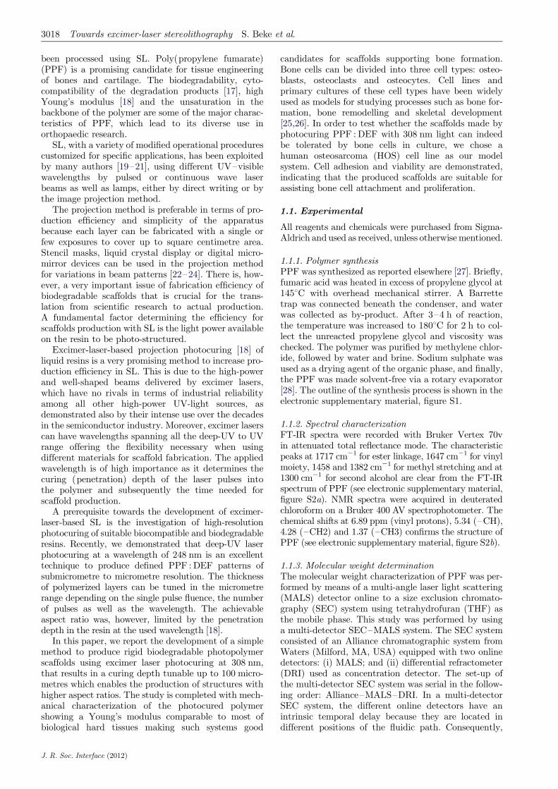
Figure 2. Pillar growth (PPF : DEF) as a function of number of pulses at 20 mJ cm22. (Online version in colour.)
3020 Towards excimer-laser stereolithography S. Beke et al.
analysed. A 20-nanometre-thick gold layer was sputteredover the polymerized arrays before the images were taken.
The cells grown on polymerized scaffolds were fixed in1.2 per cent glutaldehyde (Sigma) in 0.1 M sodium caco-dylate (Sigma) for 1 h at room temperature. Afterfixation, they were washed three times in 0.1 M sodiumcacodylate for 10 min, and twice in water for 5 min. Thecells were then incubated with increasing concentrationsof ethanol (50%, 70%, 80%, 90% and 96%) for 10 mineach. Subsequently, the cells were incubated in 100 percent ethanol for 10 min three times, before they weremoved to a glass Petri dish with 100 per cent hexamethyl-disilazane (HMDS, Sigma) for 20 min. Finally, the samplewas left overnight in 100 per cent HMDS until completeevaporation of the solution.
1.1.11. Immunostaining and confocal microscopyThe cells grown on scaffolds were fixed in 4 per cent par-aformaldehyde/4 per cent sucrose/PBS for 15 min atroom temperature and washed three times with PBS.The cells were incubated with a primary antibody againsta-tubulin (1 : 400, Invitrogen) in 5 per cent normal goatserum (Jackson Laboratories) 0.1 per cent Triton/PBS(0.1% PBT) for 1 h. Subsequently, the cells werewashed four times in 20 mM phosphate buffer pH 7.4/0.5 M NaCl and were incubated with a fluorescent sec-ondary anti-mouse antibody conjugated with Alexa488(1 : 100, Invitrogen) and Phalloidin-TexasRed (1 : 400,Invitrogen) in 5 per cent NGS/0.1 per cent PBT for1 h. The cells were washed three times in 20 mM phos-phate buffer pH 7.4/0.5 M NaCl, once in PBS and oncein water before they were mounted in ProLong GoldAntifade Reagent with DAPI (Invitrogen). Cell viabilitywas tested using LIVE/DEAD Kits for Mammalian Cells(Invitrogen), according to manufacturer’s protocol.Confocal images were obtained on a Leica TCS SP5microscope using a 63� objective (Leica Microsystems).
2. RESULTS AND DISCUSSIONS
2.1. Curing depth-vertical resolution
For a systematic investigation of the curing depth as afunction of the total irradiation dose (total fluence), a
J. R. Soc. Interface (2012)
1.2-mm round-shaped aperture was used as a mask.Owing to the 4� demagnification in the projectionsystem, 0.3-mm-diameter areas were exposed to laserirradiation. Several arrays of photocross-linked struc-tures were fabricated by applying fluence (Fp) of20 mJ cm22 per pulse and varied the number of laserpulses (Np) while moving the sample in the transversalplane. This way, an array of pillars corresponding to aspecific combination of laser pulse fluence and numberof pulses resulting in a total fluence (Ft ¼ Fp � Np)were produced and analysed. In all of our experiments,Fp ¼ 20 mJ cm22 was used for both the pillar and scaf-fold productions.
The height of the produced pillars and their pro-files as a function of number of pulses is presented infigure 2. It is obvious that this technique provides a pre-cise control on the height of the produced polymerizedstructures (curing depth). Note that because the surfaceprofiles of pillars cannot be measured on the exact diag-onal of the pillars, the presented diameters on the x-axisare just approximate values. The pillar heights weredetermined by measuring the distance between thequartz surface and the lowest part of the central‘crater’ indicated by a red line in figure 2.
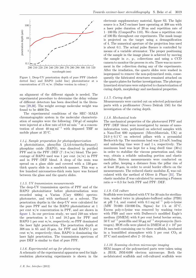
Figure 3a,b presents the curing depth as a function ofthe total fluence for the PPF : DEF blend with 1 percent BAPO and PPF with 1 per cent BAPO, respect-ively. From the plots of figure 3, it is found that forthe PPF : DEF blend, the critical total fluence abovewhich photopolymerization starts is 1000 mJ cm22,which corresponds to a curing depth of 35 mm. For thePPF, the critical total fluence is fairly decreased to120 mJ cm22 with a penetration depth of 18 mm.
The data obtained from the profil measurements of thepolymerized pillars show a correlation between the totalfluence and the thickness of the cured layers, Cd. Ingeneral, this correlation is theoretically expressed by theso-called working curve [10]
Cd ¼ Dp � lnFp � Np
Fp � Nc¼ Dp � ln
Np
Nc;
where Nc is the critical number of pulses at which photo-polymerization starts for a given fluence per pulse (Fp),
110
0 100 200 300 400 0 20 30 40 50 60 70
100
90
80
70
60
50
40
30
20
curi
ng d
epth
(mm
)
100
90
80
70
60
50
40
30
20
0 0 200 400 600 800
total fluence (mJ cm–2)
1000 1200 14002000 4000
total fluence (mJ cm–2)
6000 8000
10
no. pulsesno. pulses(a) (b)
110
curi
ng d
epth
(mm
)
PPF, 1% BAPOPPF : DEF, 1% BAPO
Figure 3. Plot of curing depth versus the total fluence: (a) PPF : DEF blend (7 : 3 w/w) with 1% BAPO and (b) pure PPF with1% BAPO. (Online version in colour.)
Towards excimer-laser stereolithography S. Beke et al. 3021
and Dp is the penetration depth. This behaviour wasindeed observed when 248 nm was used [18].
On the contrary, when 308 nm is used, the pen-etration depth of PPF is far higher than at 248 nm(figure 1); in addition, at 308 nm, the penetrationdepth of the photoinitiator (BAPO) is higher thanthat of PPF and PPF : DEF. The penetration depthat 308 nm is 65 and 25 mm, for PPF and BAPO 1 percent w/w, respectively; therefore, when using 308 nm,BAPO dominates the laser light penetration. Duringthe course of irradiation, the concentration of BAPOmolecules continuously decreases as photons from theprojected light break down the photoinitiator moleculesinto radicals along the penetration direction of the light.The radicals then bond the neighbouring polymers/monomers by breaking carbon double bonds. In thisdynamic process, the correlation between the curingdepth and total fluence is quasi-linear in contrast tothe logarithmic in our previous study when 248 nmwas used [18].
The higher total fluence necessary to achieve thecuring of the PPF : DEF blend compared with purePPF is attributed to the lower density of already-cross-linked material in the blend. Increasing the laser pulse flu-ence above Fp ¼ 100 mJ cm22 bubble formation in thepolymer resin was observed during irradiation.
We would like to point out that figure 3 demonstratesthe precise control of the curing depth of PPF at 308 nmwith a few micrometres resolution being a fundamen-tal prerequisite for the realization of an efficient SLapparatus. The broadening of the pillars on the substrateside is attributed to a spurious photocuring originatingfrom: (i) large scattering at the quartz–resin interfaceand the large energy dose used to fabricate large cross-section pillars (this was produced in order to perform thenanoindentation measurements and allow repetitivemeasurement on different points on the same pillar) and(ii) lack of oxygen at the resin–quartz interface thatlimits the termination of the photocross-linking process(oxygen is known to be a very efficient cross-linking quencher). The non-flat pillar top surface is
J. R. Soc. Interface (2012)
ascribed to non-homogeneous irradiation deep intothe resin owing to small diffraction effects, which areenhanced by the large irradiation area and therefore largeenergy dose. This effect is not present when fabricatingfreestanding structures, as shown in the following sections.
2.2. Two-dimensional structures (with round-shaped and squared-shaped pores/channels)
On the basis of characterization of simple pillarstructures, two-dimensional structures with accuratedimensions can be produced by projecting the imageof a two-dimensional mask. The masks used for theseexperiments are quartz plates with metallic coatingsof desired patterns.
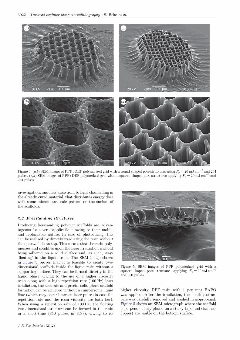
Figure 4a,b shows a two-dimensional scaffold withround-shaped channels of photopolymerized grid(PPF : DEF with 1% BAPO) when applying 264 pulses.
The actual size of each round-shaped metallic spot onthe mask is 220 mm and the spacing between them is80 mm in all directions, which results in an exposure of55 mm in diameter and 20 mm line spacing of the polymer-ized grid by using a demagnification of four.The estimatedheight of the grid based on figure 3 is about 80 mm, whichis supported by SEM analysis (figure 4a). Figure 4b isa higher magnification SEM micrograph highlightingthe internal porous structures (within the channels)that favours the cell adhesion for tissue engineering.By using masks with different dimensions, the produ-ced channel/pore sizes can be easily tuned. A scaffoldwith squared-shaped pores is shown in figure 4c,d.The same experimental conditions were used (see electro-nic supplementary material, figure S3) except forthe mask characteristics. The metal-coated squares of themask have dimensions of 127 � 127 mm with a 27-mm spa-cing. After the demagnification of four, the exposurepattern is a squared grid with a line width of 7 mm and27-mm spacing.
It is worth noticing the surface morphology of theproduced scaffolds, which presents a porous or groovedmicrometre pattern. These features are under further
20 kV 20 kV×170 ×200 20 30 SEI100 mm 100 mm
20 kV ×1000 20 30 SEI10 mm20 kV ×1000 10 mm
(a) (c)
(b) (d )
Figure 4. (a,b) SEM images of PPF : DEF polymerized grid with a round-shaped pore structures using Fp ¼ 20 mJ cm22 and 264pulses. (c,d) SEM images of PPF : DEF polymerized grid with a squared-shaped pore structures applying Fp ¼ 20 mJ cm22 and264 pulses.
3022 Towards excimer-laser stereolithography S. Beke et al.
investigation, and may arise from to light channelling inthe already cured material, that distributes energy dosewith some micrometre scale pattern on the surface ofthe scaffolds.
30 kV ×120 100 mm
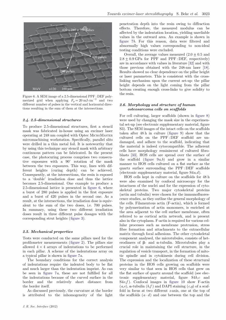
Figure 5. SEM images of PPF polymerized grid with asquared-shaped pore structures applying Fp ¼ 20 mJ cm22
and 350 pulses.
2.3. Freestanding structures
Producing freestanding polymer scaffolds are advan-tageous for several applications owing to their mobileand replaceable nature. In case of photocuring, thiscan be realized by directly irradiating the resin withoutthe quartz slide on top. This means that the resin poly-merizes and solidifies upon the laser irradiation withoutbeing adhered on a solid surface and, as such, stays‘floating’ in the liquid resin. The SEM image shownin figure 5 proves that it is feasible to create two-dimensional scaffolds inside the liquid resin without asupporting surface. They can be formed directly in theliquid phase. Owing to the use of a higher viscosityresin along with a high repetition rate (100 Hz) laserirradiation, the accurate and precise solid phase scaffoldformation can be achieved without a cumbersome liquidflow (which may occur between laser pulses in case therepetition rate and the resin viscosity are both low).When using a repetition rate of 100 Hz, the floatingtwo-dimensional structure can be formed in the resinin a short-time (350 pulses in 3.5 s). Owing to its
J. R. Soc. Interface (2012)
higher viscosity, PPF resin with 1 per cent BAPOwas applied. After the irradiation, the floating struc-ture was carefully removed and washed in isopropanol.Figure 5 shows an SEM micrograph where the scaffoldis perpendicularly placed on a sticky tape and channels(pores) are visible on the bottom surface.
30 kV ×120 100 mm
280 pulses
420 pulses
420 + 280 = 700 pulses
Figure 6. A SEM image of a 2.5-dimensional PPF : DEF poly-merized grid when applying Fp ¼ 20 mJ cm22 and twodifferent number of pulses in the vertical and horizontal direc-tions resulting in the sum of them at the intersections.
Towards excimer-laser stereolithography S. Beke et al. 3023
2.4. 2.5-dimensional structures
To produce 2.5-dimensional structures, first a stencilmask was fabricated in-house using an excimer laseroperating at 248 nm coupled with Optec MICROMASTER
micromachining workstation. Specifically, parallel slitswere drilled in a thin metal foil. It is noteworthy thatby using this technique any stencil mask with arbitrarycontinuous pattern can be fabricated. In the presentcase, the photocuring process comprises two consecu-tive exposures with a 908 rotation of the maskbetween the two exposures. This way, lines with dif-ferent heights (curing depth) can be achieved.Consequently, at the intersections, the resin is exposedto a ‘double’ irradiation dose and thus the latticebecomes 2.5-dimensional. One example to produce a2.5-dimensional lattice is presented in figure 6, wherea burst of 280 pulses is applied in the first exposureand a burst of 420 pulses in the second one. As aresult, at the intersections, the irradiation dose is equiv-alent to the sum of the two doses, i.e. 700 pulses.In summary, using these two different irradiationdoses result in three different pulse dosages with thecorresponding strut heights (figure 3).
2.5. Mechanical properties
Tests were conducted on the same pillars used for theprofilometer measurements (figure 2). The pillars sizeallowed 4 � 4 arrays of indentations to be performedin each pillar. A scheme of the indentations array ona typical pillar is shown in figure 7a.
The boundary conditions for the correct analysisof indentations require the indented body to be flatand much larger than the indentation imprint. As canbe seen in figure 7a, these are not fulfilled for allthe indentations because of the curved surface in theborder and the relatively short distance fromthe border itself.
As discussed previously, the curvature at the borderis attributed to the inhomogeneity of the light
J. R. Soc. Interface (2012)
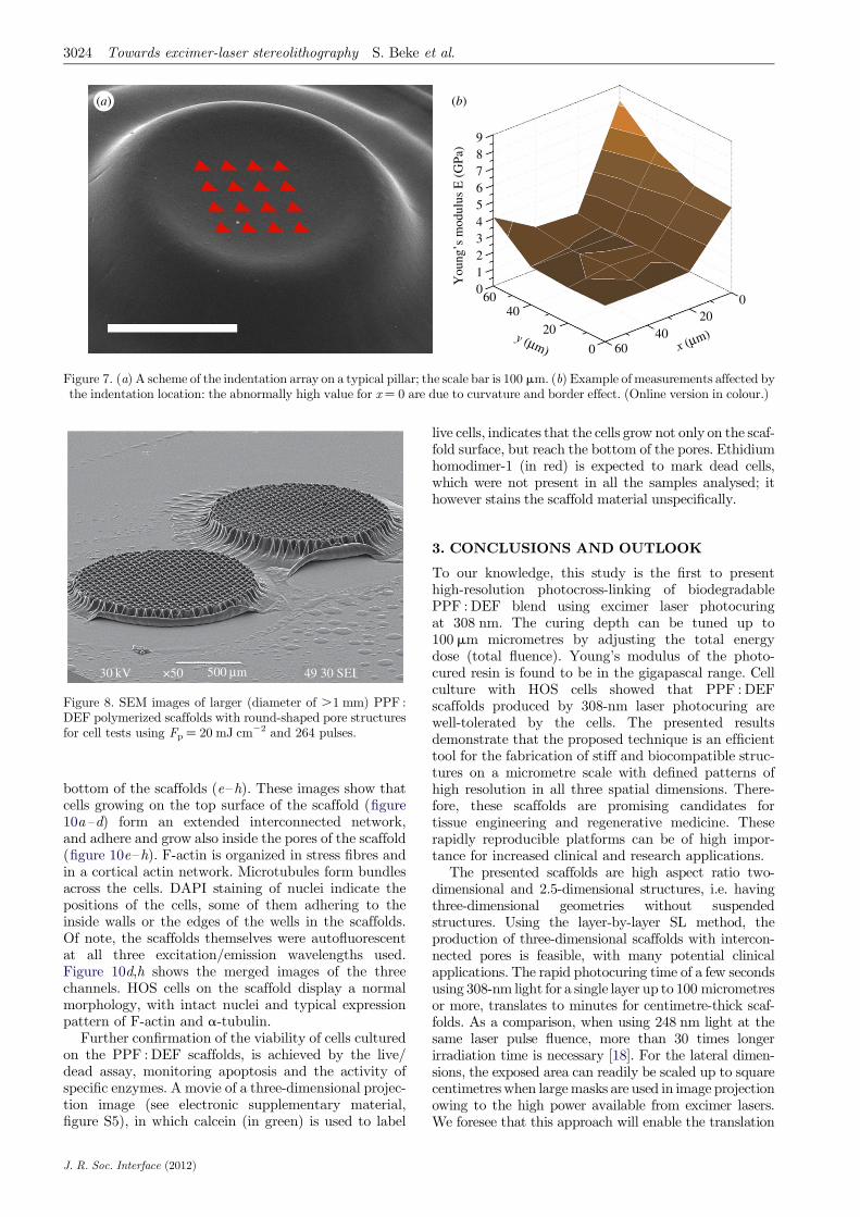
penetration depth into the resin owing to diffractioneffects. Therefore, the measured modulus can beaffected by the indentation location, yielding unreliablevalues in the outward area. An example is shown infigure 7b. For this reason, data were filtered andabnormally high values corresponding to non-idealtesting conditions were excluded.
Overall, the average values measured (2.0+0.5 and2.8+0.9 GPa for PPF and PPF : DEF, respectively)are in accordance with values in literature [32] and withthose previous obtained with the 248-nm laser [18].Results showed no clear dependence on the pillar heightor laser parameters. This is consistent with the cross-linking mechanism upon the current set-up: the pillarheight depends on the light coming from the pillarbottom creating enough cross-links to give solidity tothe resin.
2.6. Morphology and structure of humanosteosarcoma cells on scaffolds
For cell culturing, larger scaffolds (shown in figure 8)were used by changing the mask size in the experimen-tal set-up (see electronic supplementary material, figureS3). The SEM images of the intact cells on the scaffoldstaken after 48 h in culture (figure 9) show that thecultured cells on the PPF : DEF scaffold are un-damaged, and adhere to the scaffold, indicating thatthe material is indeed cytocompatible. The adherentcells have morphology reminiscent of cultured fibro-blasts [33]. HOS cells are spread over the surface ofthe scaffold (figure 9a,b) and grow in a similarmanner to HOS cells cultured on a flat surface as thequartz surface surrounding the PPF : DEF scaffolds(electronic supplementary material, figure S4a,d).
HOS cells kept in culture on the scaffolds for 48 hwere also examined by confocal microscopy for theintactness of the nuclei and for the expression of cyto-skeletal proteins. Two major cytoskeletal proteins(actin and tubulin) were chosen for the immunofluores-cence studies, as they outline the general morphology ofthe cells. Filamentous actin (F-actin), which is formedby polymerization of actin monomers, is enriched atthe area adjacent to the cell surface membrane, oftenreferred to as cortical actin network, and is presentalso in the cytoplasm. F-actin is required for various cel-lular processes such as membrane protrusion, stressfibre formation and attachments to the extracellularmatrix through focal adhesions. The other cytoskeletalcomponent analysed, the microtubules, consists of het-erodimers of b- and a-tubulin. Microtubules play acrucial role in maintaining the cell structure, in theregulation of vesicle transport, in the formation of mito-tic spindle and in cytokinesis during cell division.The expression and the localization of these structuralproteins in the HOS cells growing on scaffolds werevery similar to that seen in HOS cells that grew onthe flat surface of quartz around the scaffold (see elec-tronic supplementary material, figure S4b,c andS4e,f ). Confocal images in figure 10 show F-actin(a,e), a-tubulin (b,f ) and DAPI staining (c,g) of a scaf-fold in focus at two different z-axis, one at the top ofthe scaffolds (a–d) and one between the top and the
9876543210
You
ng’s
mod
ulus
E (
GPa
)
6040
20
0 6040
x (mm)y (mm)
200
(a) (b)
Figure 7. (a) A scheme of the indentation array on a typical pillar; the scale bar is 100 mm. (b) Example of measurements affected bythe indentation location: the abnormally high value for x ¼ 0 are due to curvature and border effect. (Online version in colour.)
30 kV ×50 49 30 SEI500 mm
Figure 8. SEM images of larger (diameter of .1 mm) PPF :DEF polymerized scaffolds with round-shaped pore structuresfor cell tests using Fp ¼ 20 mJ cm22 and 264 pulses.
3024 Towards excimer-laser stereolithography S. Beke et al.
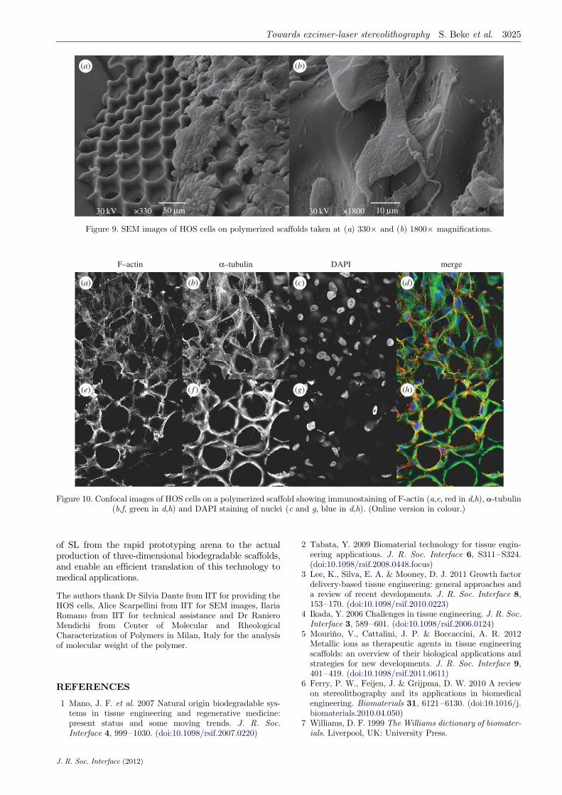
bottom of the scaffolds (e–h). These images show thatcells growing on the top surface of the scaffold (figure10a–d) form an extended interconnected network,and adhere and grow also inside the pores of the scaffold(figure 10e–h). F-actin is organized in stress fibres andin a cortical actin network. Microtubules form bundlesacross the cells. DAPI staining of nuclei indicate thepositions of the cells, some of them adhering to theinside walls or the edges of the wells in the scaffolds.Of note, the scaffolds themselves were autofluorescentat all three excitation/emission wavelengths used.Figure 10d,h shows the merged images of the threechannels. HOS cells on the scaffold display a normalmorphology, with intact nuclei and typical expressionpattern of F-actin and a-tubulin.
Further confirmation of the viability of cells culturedon the PPF : DEF scaffolds, is achieved by the live/dead assay, monitoring apoptosis and the activity ofspecific enzymes. A movie of a three-dimensional projec-tion image (see electronic supplementary material,figure S5), in which calcein (in green) is used to label
J. R. Soc. Interface (2012)
live cells, indicates that the cells grow not only on the scaf-fold surface, but reach the bottom of the pores. Ethidiumhomodimer-1 (in red) is expected to mark dead cells,which were not present in all the samples analysed; ithowever stains the scaffold material unspecifically.
3. CONCLUSIONS AND OUTLOOK
To our knowledge, this study is the first to presenthigh-resolution photocross-linking of biodegradablePPF : DEF blend using excimer laser photocuringat 308 nm. The curing depth can be tuned up to100 mm micrometres by adjusting the total energydose (total fluence). Young’s modulus of the photo-cured resin is found to be in the gigapascal range. Cellculture with HOS cells showed that PPF : DEFscaffolds produced by 308-nm laser photocuring arewell-tolerated by the cells. The presented resultsdemonstrate that the proposed technique is an efficienttool for the fabrication of stiff and biocompatible struc-tures on a micrometre scale with defined patterns ofhigh resolution in all three spatial dimensions. There-fore, these scaffolds are promising candidates fortissue engineering and regenerative medicine. Theserapidly reproducible platforms can be of high impor-tance for increased clinical and research applications.
The presented scaffolds are high aspect ratio two-dimensional and 2.5-dimensional structures, i.e. havingthree-dimensional geometries without suspendedstructures. Using the layer-by-layer SL method, theproduction of three-dimensional scaffolds with intercon-nected pores is feasible, with many potential clinicalapplications. The rapid photocuring time of a few secondsusing 308-nm light for a single layer up to 100 micrometresor more, translates to minutes for centimetre-thick scaf-folds. As a comparison, when using 248 nm light at thesame laser pulse fluence, more than 30 times longerirradiation time is necessary [18]. For the lateral dimen-sions, the exposed area can readily be scaled up to squarecentimetres when large masks are used in image projectionowing to the high power available from excimer lasers.We foresee that this approach will enable the translation
30 kV 30 kV ×1800×330 50 mm 10 mm
(a) (b)
Figure 9. SEM images of HOS cells on polymerized scaffolds taken at (a) 330� and (b) 1800� magnifications.
(a) (b) (c) (d)
(e) ( f ) (g) (h)
F–actin a–tubulin DAPI merge
Figure 10. Confocal images of HOS cells on a polymerized scaffold showing immunostaining of F-actin (a,e, red in d,h), a-tubulin(b,f, green in d,h) and DAPI staining of nuclei (c and g, blue in d,h). (Online version in colour.)
Towards excimer-laser stereolithography S. Beke et al. 3025
of SL from the rapid prototyping arena to the actualproduction of three-dimensional biodegradable scaffolds,and enable an efficient translation of this technology tomedical applications.
The authors thank Dr Silvia Dante from IIT for providing theHOS cells, Alice Scarpellini from IIT for SEM images, IlariaRomano from IIT for technical assistance and Dr RanieroMendichi from Center of Molecular and RheologicalCharacterization of Polymers in Milan, Italy for the analysisof molecular weight of the polymer.
REFERENCES
1 Mano, J. F. et al. 2007 Natural origin biodegradable sys-tems in tissue engineering and regenerative medicine:present status and some moving trends. J. R. Soc.Interface 4, 999–1030. (doi:10.1098/rsif.2007.0220)
J. R. Soc. Interface (2012)
2 Tabata, Y. 2009 Biomaterial technology for tissue engin-eering applications. J. R. Soc. Interface 6, S311–S324.(doi:10.1098/rsif.2008.0448.focus)
3 Lee, K., Silva, E. A. & Mooney, D. J. 2011 Growth factordelivery-based tissue engineering: general approaches anda review of recent developments. J. R. Soc. Interface 8,153–170. (doi:10.1098/rsif.2010.0223)
4 Ikada, Y. 2006 Challenges in tissue engineering. J. R. Soc.Interface 3, 589–601. (doi:10.1098/rsif.2006.0124)
5 Mourino, V., Cattalini, J. P. & Boccaccini, A. R. 2012Metallic ions as therapeutic agents in tissue engineeringscaffolds: an overview of their biological applications andstrategies for new developments. J. R. Soc. Interface 9,401–419. (doi:10.1098/rsif.2011.0611)
6 Ferry, P. W., Feijen, J. & Grijpma, D. W. 2010 A reviewon stereolithography and its applications in biomedicalengineering. Biomaterials 31, 6121–6130. (doi:10.1016/j.biomaterials.2010.04.050)
7 Williams, D. F. 1999 The Williams dictionary of biomater-ials. Liverpool, UK: University Press.

3026 Towards excimer-laser stereolithography S. Beke et al.
8 Hutmacher, D. W., Michael, S. & Makarand, R. V. 2004Scaffold-based tissue engineering: rationale for computer-aided design and solid free-form fabrication systems.Trends Biotechnol. 22, 354–362. (doi:10.1016/j.tibtech.2004.05.005)
9 Yang, S., Leong, K. F., Du, Z. & Chua, C. K. 2001 Thedesign of scaffolds for use in tissue engineering. I.Traditional factors. Tissue Eng. 7, 679–689. (doi:10.1089/107632701753337645)
10 Farsari, M., Claret-Tournier, F., Huang, S., Chatwin,C. R., Budgett, D. M., Birch, P. M., Young, R. C. D. &Richardson, J. D. 2000 A novel high-accuracy microstereo-lithography method employing an adaptive electro-opticmask. J. Mater. Process Technol. 107, 167–172. (doi:10.1016/S0924-0136(00)00672-5)
11 Bertsch, A., Jiguet, S. & Renaud, P. 2004 Microfabricationof ceramic components by microstereolithography.J. Micromech. Microeng. 14, 197–203. (doi:10.1088/0960-1317/14/2/005)
12 Choi, J. W., Ha, Y. M., Choi, K. H. & Lee, S. H. 2007Fabrication of 3-dimensional microstructures usingdynamic image projection. Key Eng. Mater. 39,473–478. (doi:10.4028/www.scientific.net/KEM.339.473)
13 Choi, J. W., Ha, Y. M., Lee, S. H. & Choi, K. H. 2006Design of microstereolithography system based ondynamic image projection for fabrication of three-dimensional microstructures. J. Mech. Sci. Technol. 20,2094–2104. (doi:10.1007/BF02916326)
14 Choi, J. W., Wicker, R. B., Cho, S. H., Ha, C. S. & Lee,S. H. 2009 Cure depth control for complex 3D micro-structure fabrication in dynamic mask projectionmicrostereolithography. Rapid Prototyping J. 15, 59–70.(doi:10.1108/13552540910925072)
15 Limaye, A. S. & Rosen, D. W. 2007 Process planningmethod for mask projection microstereolithography.Rapid Prototyping J. 13, 76–84. (doi:10.1108/13552540710736759)
16 Ha, Y. M., Choi, J. W. & Lee, S. H. 2008 Mass productionof 3-D microstructures using projection microstereolitho-graphy. J. Mech. Sci. Technol. 22, 514–521. (doi:10.1007/s12206-007-1031-8)
17 Kasper, K. F., Tanahashi, K., Fisher, J. P. & Mikos, A. G.2009 Synthesis of poly(propylene fumarate). Nat. Protocol4, 518–525. (doi:10.1038/nprot.2009.24)
18 Brandi, F., Anjum, F., Ceseracciu, L., Barone, A. C. &Athanassiou, A. 2011 Rigid biodegradable photopolymerstructures of high resolution using deep-UV laser photo-curing. J. Micromech. Microeng. 21, 054007. (doi:10.1088/0960-1317/21/5/054007)
19 Lee, S. J., Kang, H. W., Park, J. K., Rhie, J. W., Hahn,S. K. & Cho, D. W. 2008 Application of microstereo-lithography in the development of three-dimensionalcartilage regeneration scaffolds. Biomed. Microdevices10, 233–241. (doi:10.1007/s10544-007-9129-4)
20 Mapili, G., Lu, Y., Chen, S. & Roy, K. 2005 Laser-layeredmicrofabrication of spatially patterned functionalizedtissue engineering scaffolds. J. Biomed. Mater. Res. B75B, 414–424. (doi:10.1002/jbm.b.30325)
J. R. Soc. Interface (2012)
21 Arcaute, K., Mann, B. K. & Wicker, R. B. 2006 Stereo-lithography of three-dimensional bioactive poly(ethyleneglycol) constructs with encapsulated cells. Ann. Biomed.Eng. 34, 1429–1441. (doi:10.1007/s10439-006-9156-y)
22 Lee, D., Miyoshi, T., Takaya, Y. & Ha, T. 2006 3D micro-fabrication of photosensitive resin reinforced with ceramicnanoparticles using LCD microstereolithography. J. LaserMicro/Nanoeng. 1, 142–148. (doi:10.2961/jlmn.2006.02.0011)
23 Wu, S., Han, L. H. & Chen, S. 2009 Three-dimensionalselective growth of nanoparticles on a polymer microstruc-ture. Nanotechnology 20, 285312. (doi:10.1088/0957-4484/20/28/285312)
24 Han, L. H., Mapili, G., Chen, S. & Roy, K. 2008 Projectionmicrofabrication of three-dimensional scaffolds for tissueengineering. J. Manuf. Sci. Eng. 130, 021005. (doi:10.1115/1.2823079)
25 Kartsogiannis, V. & Ng, K. W. 2004 Cell lines andprimary cell cultures in the study of bone cell biology.Mol. Cell Endocrinol. 228, 79–102. (doi:10.1016/j.mce.2003.06.002)
26 Mourino, V. & Boccaccini, A. R. 2010 Bone tissue engin-eering therapeutics: controlled drug delivery in three-dimensional scaffolds. J. R. Soc. Interface 7, 209–227.(doi:10.1098/rsif.2009.0379)
27 Wang, S., Lu, L. C., Gruetzmacher, J. A., Currier, B. L. &Yaszemski, M. J. 2005 A biodegradable and cross-linkablemultiblock copolymer consisting of poly(propylenefumarate) and poly(1-caprolactone): synthesis, character-ization, and physical properties. Macromolecules 38,7358–7370. (doi:10.1021/ma050884c)
28 Lee, K. W., Wang, S. F., Lu, L. C., Jabbari, E., Currier,B. L. & Yaszemski, M. J. 2006 Fabrication and character-ization of poly(propylene fumarate) scaffolds withcontrolled pore structures using 3-dimensional printingand injection molding. Tissue Eng. 12, 2801–2811.(doi:10.1089/ten.2006.12.2801)
29 Mendichi, R. & Giachometti Schieroni, A. G. 2001 Use of amulti-detector size exclusion chromatography system forthe characterization of complex polymers. Curr. TrendsPolym. Sci. 6, 17–32.
30 Wyatt, P. J. 1993 Light scattering and the absolutecharacterization of macromolecules. Anal. Chem. Acta272, 1–40. (doi:10.1016/0003-2670(93)80373-S)
31 Oliver, W. C. & Pharr, G. M. 1992 An improved techniquefor determining hardness and elastic modulus using load adisplacement sensing indentation experiments. J. Mater.Res. 7, 1565–1583. (doi:10.1557/JMR.1992.1564)
32 Fisher, J. P., Timmer, M. D., Holland, T. A., Dean, D.,Engel, P. S. & Mikos, A. G. 2003 Photoinitiatedcross-linking of the biodegradable polyester poly(propy-lene fumarate): part I. Determination of networkstructure. Biomacromolecules 4, 1327–1334. (doi:10.1021/bm030028d)
33 Murr, L. E. 2006 Biological issues in materials scienceand engineering: interdisciplinarity and the bio-materialsparadigm. JOM 58, 23–33. (doi:10.1007/s11837-006-0136-3)
Copyright © 2022 FDOKUMEN


![Ratiometry of Monomer/Excimer Emissions of Dipyrenyl Calix[4]arene in Aqueous Media](https://static.fdokumen.com/doc/165x107/63155d5385333559270d17fd/ratiometry-of-monomerexcimer-emissions-of-dipyrenyl-calix4arene-in-aqueous-media.jpg)