Photopolymer diffractive optical elements in electronic speckle pattern shearing interferometry
11
Dublin Institute of Technology ARROW@DIT Articles Centre for Industrial and Engineering Optics 1-1-2006 Photopolymer Diffractive Optical Elements in Electronic Speckle Pattern Shearing Interferometry Emilia Mihaylova Dublin Institute of Technology, [email protected] Izabela Naydenova Dublin Institute of Technology, [email protected] Barry Duignan Dublin Institute of Technology, [email protected] Suzanne Martin Dublin Institute of Technology, [email protected] Vincent Toal Dublin Institute of Technology, [email protected] This Article is brought to you for free and open access by the Centre for Industrial and Engineering Optics at ARROW@DIT. It has been accepted for inclusion in Articles by an authorized administrator of ARROW@DIT. For more information, please contact [email protected]. Recommended Citation Mihaylova, Emilia et al:Photopolymer Ddiffractive Optical Elements in Electronic Speckle Pattern Shearing Interferometry. Optics and Lasers in Engineering, Volume 44, Issue 9, September 2006, Pages 965-974.
Transcript of Photopolymer diffractive optical elements in electronic speckle pattern shearing interferometry

Dublin Institute of TechnologyARROW@DIT
Articles Centre for Industrial and Engineering Optics
1-1-2006
Photopolymer Diffractive Optical Elements inElectronic Speckle Pattern Shearing InterferometryEmilia MihaylovaDublin Institute of Technology, [email protected]
Izabela NaydenovaDublin Institute of Technology, [email protected]
Barry DuignanDublin Institute of Technology, [email protected]
Suzanne MartinDublin Institute of Technology, [email protected]
Vincent ToalDublin Institute of Technology, [email protected]
This Article is brought to you for free and open access by the Centre forIndustrial and Engineering Optics at ARROW@DIT. It has been acceptedfor inclusion in Articles by an authorized administrator of [email protected] more information, please contact [email protected].
Recommended CitationMihaylova, Emilia et al:Photopolymer Ddiffractive Optical Elements in Electronic Speckle Pattern Shearing Interferometry. Opticsand Lasers in Engineering, Volume 44, Issue 9, September 2006, Pages 965-974.
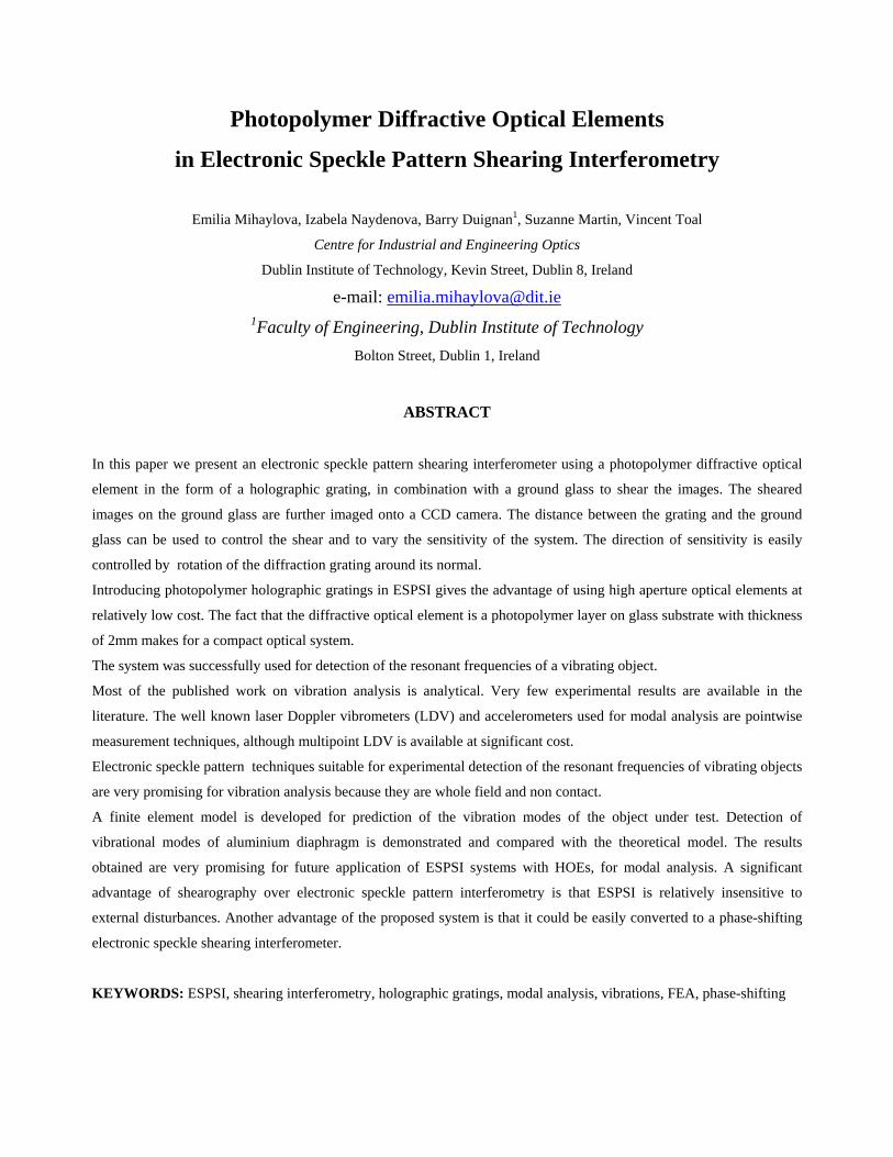
Photopolymer Diffractive Optical Elements
in Electronic Speckle Pattern Shearing Interferometry
Emilia Mihaylova, Izabela Naydenova, Barry Duignan1, Suzanne Martin, Vincent Toal
Centre for Industrial and Engineering Optics
Dublin Institute of Technology, Kevin Street, Dublin 8, Ireland
e-mail: [email protected] of Engineering, Dublin Institute of Technology
Bolton Street, Dublin 1, Ireland
ABSTRACT
In this paper we present an electronic speckle pattern shearing interferometer using a photopolymer diffractive optical
element in the form of a holographic grating, in combination with a ground glass to shear the images. The sheared
images on the ground glass are further imaged onto a CCD camera. The distance between the grating and the ground
glass can be used to control the shear and to vary the sensitivity of the system. The direction of sensitivity is easily
controlled by rotation of the diffraction grating around its normal.
Introducing photopolymer holographic gratings in ESPSI gives the advantage of using high aperture optical elements at
relatively low cost. The fact that the diffractive optical element is a photopolymer layer on glass substrate with thickness
of 2mm makes for a compact optical system.
The system was successfully used for detection of the resonant frequencies of a vibrating object.
Most of the published work on vibration analysis is analytical. Very few experimental results are available in the
literature. The well known laser Doppler vibrometers (LDV) and accelerometers used for modal analysis are pointwise
measurement techniques, although multipoint LDV is available at significant cost.
Electronic speckle pattern techniques suitable for experimental detection of the resonant frequencies of vibrating objects
are very promising for vibration analysis because they are whole field and non contact.
A finite element model is developed for prediction of the vibration modes of the object under test. Detection of
vibrational modes of aluminium diaphragm is demonstrated and compared with the theoretical model. The results
obtained are very promising for future application of ESPSI systems with HOEs, for modal analysis. A significant
advantage of shearography over electronic speckle pattern interferometry is that ESPSI is relatively insensitive to
external disturbances. Another advantage of the proposed system is that it could be easily converted to a phase-shifting
electronic speckle shearing interferometer.
KEYWORDS: ESPSI, shearing interferometry, holographic gratings, modal analysis, vibrations, FEA, phase-shifting

1. INTRODUCTION
Electronic speckle pattern shearing interferometry (ESPSI) is an optical technique that enables full-field and non-contact
direct measurements of displacement derivatives to be made [1-8]. A common method for generating two sheared
images of the object in ESPSI systems is to use a Michelson interferometric optical set-up. The shear is introduced and
controlled by tilting one of the mirrors.
The idea of using a holographic grating for shearing of the two images in speckle shearing interferometry is not new.
Some early non-electronic systems used photographic gratings [5-7], but the use of CCD cameras enables observation of
real-time fringe formation [8, 9]. Recently there has been an increasing interest in the application of shearography for
modal analysis of vibrating objects. New interferometric systems are of interest for engineering and industrial
applications.
We present the use of photopolymer holographic grating in a ESPSI system for modal analysis. Self-processing
acrylamide based photopolymer [10] is used as a recording medium for recording holographic gratings. The optimized
photopolymer material gives good diffraction efficiencies up to 94% for an exposure of 80 mJ/cm2 and it performs well
in the transmission mode of hologram recording. The holographic grating is used in combination of a ground glass to
shear the images and to control the size of the shear.
2. THEORY
When two light waves interfere, the following equation [11] relates their relative phase Φ at a point to their relative
geometrical path difference L:
βλπ
−=Φ nL2 (1)
where λ is the wavelength of the laser light, n is the refractive index of the medium through which the laser light is
transmitted, and β is a constant phase. The change in the relative phase ∆=δΦ or phase change, which manifests as
visible fringes, can be effected by an incremental change in any of the three parameters λ, n, and L. Thus,
LnnLLnLL
nn
δλπδ
λπδλ
λπδδδλ
λ222
2 ++−=∂Φ∂
+∂Φ∂
+∂Φ∂
=∆ (2)
where δλ, δn, and δL denote respectively, the incremental change in wavelength, in refractive index and the difference in
relative geometrical path length of the interfering waves.

If the same wavelength is used and the test environment is still air, only the δL term in Eq. (2) is nonzero, resulting in the
following equation for the phase change [12]:
[ wCvBuA δδδλ
]π++=∆
2 (3)
where u, v and w are the displacement components of the point P’(x+∆x, y+∆y, z+∆z) relative to point P (x, y, z) on the
test surface, and A, B, and C are sensitivity factors that are related to the optical arrangement. When a diffraction grating
is used to introduce the shear the direction in which the system is sensitive can be precisely controlled by changing the
orientation of the grating. If the grating introduces small image shearing ∆x (Fig. 1 a), the displacement terms in Eq. (3)
can be expressed in terms of partial derivatives:
xxwC
xvB
xuA ∆⎥⎦
⎤⎢⎣⎡
∂∂
+∂∂
+∂∂
=∆λπ2
(4)
If the introduced shear is in the y direction (Fig. 1 b) the phase difference is:
yywC
yvB
yuA ∆⎥
⎦
⎤⎢⎣
⎡∂∂
+∂∂
+∂∂
=∆λπ2
(5)
In the most general case, when the grating is oriented as shown in Fig. 1 c
sswC
svB
suA ∆⎥⎦
⎤⎢⎣⎡
∂∂
+∂∂
+∂∂
=∆λπ2
, (6)
Where ∆s is the amount of shear in direction s, determined by the angle α (Fig. 1 c).
a) a) P’ ( x+∆x, y, z)
P ( x, y, z)P ( x, y, z)
( x+∆x, y, z)P’
x
y
z P’Px
yy
z z PP
P’P’
x
b) b)
P ( x, y, z)
P’ ( x, y+∆y, z)
x
y
z P’
P
P ( x, y, z)
P’ ( x, y+∆y, z)P’P’
x
yy
z z PPx
c) c)
P’P’ ( x+∆x, y+∆y, z)( x+∆x, y+∆y
P ( x, y, z)P ( x, y, z)
P’
Ps
x
y
z α
P’P’
PPs
xxxxx
y
z α
y
z α
y
z α
y
z z y
αs
Fig. 1. Simple control of the shearing direction by rotation of the holographic diffraction grating.

In our case (Fig. 2) the object beam lies in the (x, z) plane so there is no sensitivity in the y direction. In addition the
grating orientation was as shown in Fig. 1a. The phase change is:
xxwC
xuA ∆⎥⎦
⎤⎢⎣⎡
∂∂
+∂∂
=∆λπ2
(7)
Consider the situation of an ESPSI system with one holographic grating in front of the CCD camera and small image
shear ∆x. The phase difference ∆ can be expressed as [8]:
( ) xxw
xu
∆⎥⎦⎤
⎢⎣⎡ +
∂∂
+∂∂
=∆ θθλπ cos1sin2
(8)
The dark fringes correspond to ∆ = 2nπ, where n is the fringe order. In this case:
( )xn
xw
xu
∆=+
∂∂
+∂∂ λθθ cos1sin (9)
Fig.2. ESPSI system for vibration measurements with one photopolymer grating
object
CCD camera
imaging lens
photopolymer holographic grating
ground glass
Loudspeaker
Signal generator
θ
z
x laser

3. EXPERIMENT
Photopolymer diffractive optical element
Holographic gratings with spatial frequencies of 200 lines/mm and 500 lines/mm were recorded using the second
harmonic of a CW NdYVO4 laser (λ = 532nm). The IEO acrylamide based photopolymer, which is self-developing, was
used as the photosensitive medium. The layers were 100µm thick. Recording time and intensity were 20s and
3.5mW/cm2 respectively. The diameter of these gratings is 40mm. Diffraction efficiency in the +1 order is 60%. One of
the advantages of this material is that characteristics such as diffraction efficiency, thickness (which controls selectivity),
slant angle, diameter and reconstruction wavelength and angle can all be chosen to suit the specific application. The IEO
photopolymer is characterized by low scattering and this is important when the imaging properties of the optical system
are of concern.
Experimental set-up
The scheme of the ESPSI system with a single photopolymer holographic grating is presented in Fig. 2. A similar
system had been developed in our laboratory for static measurements and is described in detail elsewhere [13]. A
Helium-Neon laser, with wavelength 633 nm and output power of 20 mW, is used as the light source. The laser beam
illuminates the object at an angle θ = 30° to the normal to the object surface. A lens images the object onto a ground
glass, which acts as a diffusing screen. A holographic photopolymer diffraction grating is placed in front of the ground
glass. The intensities of the zero and the first order of diffraction were equalized by rotation of the grating. The rotation
of the grating around the central axis, parallel to y-axis, leads to slight off-Bragg angular adjustment and decrease in the
intensity of the first order thus offering the possibility for fine adjustment of both image and sheared image intensities.
Control of the shearing amount and shearing direction
Easy control of the shearing amount is important because it determines the overall sensitivity of the system, see Eq. 9.
The shearing amount can be controlled by changing the relative position of the ground glass and the diffraction grating
as shown in Fig. 1. The increase of the distance between the two elements leads to increase of the amount of shear and
increase of the sensitivity of the system. When the distance between the two elements is kept constant the shearing
amount can be changed by utilizing diffraction gratings with different spatial frequencies. The higher is the spatial
frequency the bigger is the amount of the shear. The spatial frequency of the grating influences also other important
parameters of the system such as the contrast of the obtained ESPSI fringes and the size of the field of view. They will be
discussed in the experimental section.
The rotation of the grating around its normal leads to a change in the shearing direction and thus controls the shearing
direction and the direction of sensitivity.
The ESPSI system using HOE to shear the image is easy to apply in a phase-shifting mode. Mounting the glass plate or
the HOE on a piezoelectric transducer (PZT) allows the introduction of a known phase shift.

a
b Fig. 3. Control of the shear
Influence of the spatial frequency of the grating on the ESPSI fringes contrast and the size of the region under study
In order to study the influence of the spatial frequency of the gratings on the quality of the obtained ESPSI fringes
diffraction gratings with spatial frequencies of 200 and 500 l/mm were used. The system was evaluated by conducting
two sets of experiments using a simple three point bending test, one with each grating. The shear was varied from 1 mm
to 12 mm simply by varying the distance between the photopolymer holographic grating and the ground glass (Fig. 3).
It was observed that the ESPSI fringes obtained with the grating having spatial frequency 500 lines/mm have better
contrast. When the spatial frequency of the grating is low (Fig. 4a), due to its lower angular selectivity, the diffraction
orders –1 and or +2 are visible in addition to the main orders 0 and +1.
a b
Fig.4. Propagation of the beams through the shearing device of holographic grating and ground glass: a) grating with smaller
spatial frequency; b) grating with bigger spatial frequency

The intensity of the additional orders is smaller but nevertheless they affect the contrast of the ESPSI fringes obtained. If
the spatial frequency of the diffraction grating is high (Fig. 4b) the contrast is better as the two main orders only are
projected onto the glass plate.
It was also observed that the size of the field of view strongly depends on the spatial frequency of the grating. When a
high spatial frequency grating was used the field of view with good contrast of the ESPSI fringes is considerably
decreased. We ascribe this observation to the fact that higher spatial frequency grating is characterised by higher angular
selectivity and in this case only small part of the light scattered by the object surface satisfies the Bragg condition for
reconstruction of the image in the +1 order. Taking into account the considerations above a 500 l/mm spatial frequency
grating was chosen for the experiments in dynamic mode of loading of the object.
The ESPSI system described above with a grating 500 lines/mm was used for studying the vibration modes of an edge
clamped aluminium diaphragm (75 mm diameter, 0.5 mm thick). The diaphragm was excited at different frequencies in
the range from 2000 Hz to 7000 Hz by a loudspeaker placed behind it. The loudspeaker is driven by a sinusoidal signal
of amplitude 0.5 V or 1V. Time-averaged TV shearography was used for all vibration studies. In addition to the ESPSI
experimental technique, theoretical predictions of resonant frequencies based on Ansys 8.1 package are also presented.
4. RESULTS AND DISCUSSION
The ESPSI system using holographic grating and a ground glass to shear the image was used to record different vibrating
modes of the an edge clamped aluminium diaphragm (Fig. 5 and Fig. 6). A filter with a 3x3 window was used to reduce
the speckle noise in the images. The experimental results show that the ESPSI system used is suitable for detection of the
resonant frequencies of the vibrating aluminium diaphragm. The detection principle is based on the fact that clear fringe
patterns with fringe contrast above 90% appear only at resonant frequencies. The introduction of different shear does not
affect the mode shape.
clamped aluminium diaphragm. The shear is 8 mm. The amplitude of the
2100 Hz 3800 Hz 5200 Hz 6200 Hz
Fig. 5. ESPSI vibration modes of a central part of an edge
sinusoidal signal driving the loudspeaker is 1V. The field of view is 23 mm x 23 mm
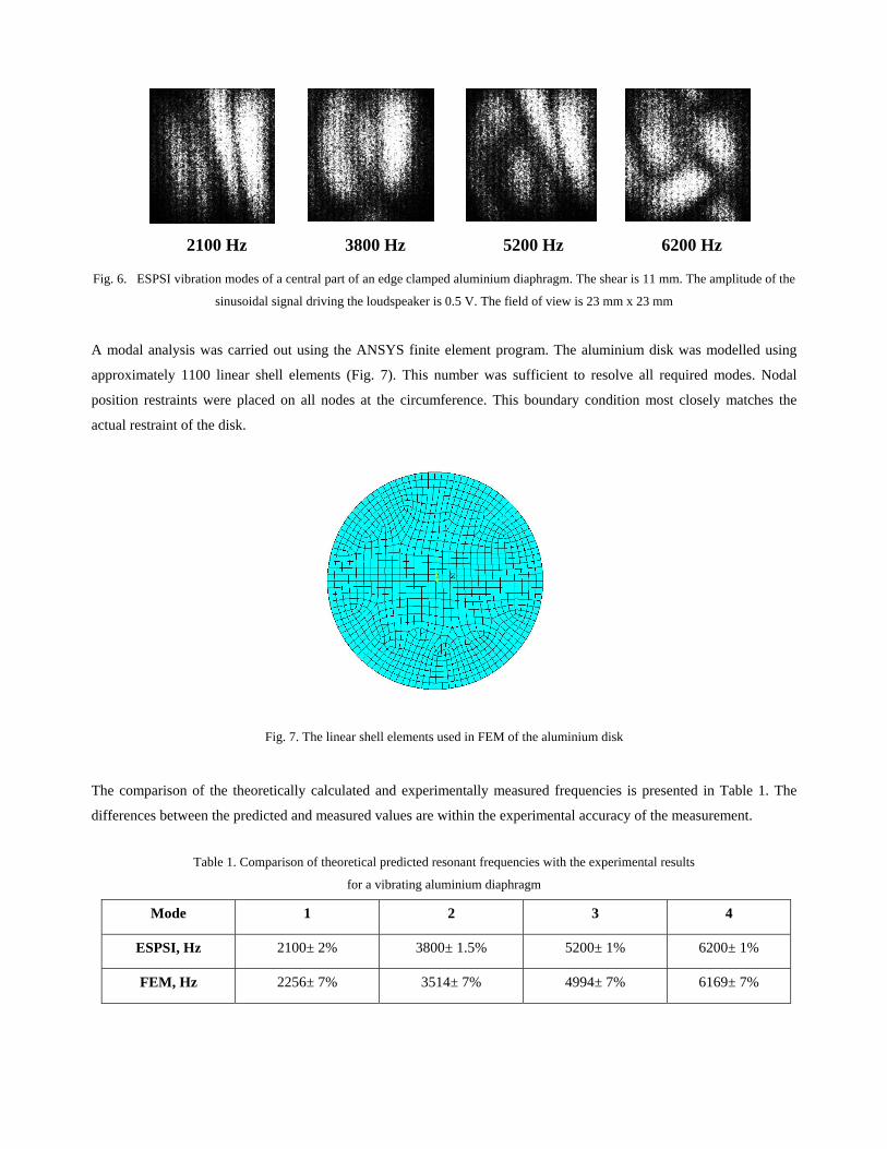
2100 Hz 3800 Hz 5200 Hz 6200 Hz
Fig. 6. ESPSI vibration modes of a central part of an edge clamped aluminium diaphragm. The shear is 11 mm. The amplitude of the
sinusoidal signal driving the loudspeaker is 0.5 V. The field of view is 23 mm x 23 mm
A modal analysis was carried out using the ANSYS finite element program. The aluminium disk was modelled using
approximately 1100 linear shell elements (Fig. 7). This number was sufficient to resolve all required modes. Nodal
position restraints were placed on all nodes at the circumference. This boundary condition most closely matches the
actual restraint of the disk.
Fig. 7. The linear shell elements used in FEM of the aluminium disk
The comparison of the theoretically calculated and experimentally measured frequencies is presented in Table 1. The
differences between the predicted and measured values are within the experimental accuracy of the measurement.
Table 1. Comparison of theoretical predicted resonant frequencies with the experimental results
for a vibrating aluminium diaphragm
Mode 1 2 3 4
ESPSI, Hz 2100± 2% 3800± 1.5% 5200± 1% 6200± 1%
FEM, Hz 2256± 7% 3514± 7% 4994± 7% 6169± 7%

5. CONCLUSIONS
It is demonstrated that the ESPSI systems using holographic optical elements to shear the image are simple and flexible
and offer a simple way to introduce discrete shear steps between two images and thus to control the sensitivity of the
system. Another advantage of these systems is that it is easy to change the shearing direction by rotating of the grating
around its normal. Advantages include also the low cost of such a system and the potential to use large apertures.
The paper shows that the ESPSI systems using holographic optical elements can be used for the analysis of vibrating
systems. High contrast interference patterns at characteristic frequencies of vibration of the object under study were
recorded. A theoretical model of the vibrating object was generated using Ansys 8.1 Package. The theoretical results
obtained for the resonant frequencies are in very good agreement with the resonant frequencies extracted from the
experiments. The experimental results obtained are promising for future applications of these systems for modal analysis.
Larger aperture HOEs are currently being prepared so that the potential for modal mapping can be fully assessed.
We therefore conclude that photopolymer HOEs can be used to make simple shearing systems, which can analyse and
possibly map the modal behaviour of vibrating objects. The results indicate that the potential for such systems in full
field modal analysis is significant.
ACKNOWLEDGMENTS
Acknowledgements are made to Technological Sector Research Programme Strand III supported by the Irish
Government. Emilia Mihaylova and Izabela Naydenova would like to thank the Arnold F. Graves Scholar Programme
and FOCAS at Dublin Institute of Technology.
REFERENCES
1. C. Joenathan C. and Torroba R., “Simple electronic speckle shearing pattern interferometer”, Opt. Lett. 15 (20),
1159-1161 (1990).
2. R. S. Sirohi, “Speckle methods in experimental mechanics”, in Speckle Metrology, Ed. R. S. Sirohi, Mercel Dekker,
New York (1993).
3. Y. M. He, C. J. Tay, H. M. Shang, “Digital phase-shifting shearography for slope measurement", Opt. Eng. 38 (9),
1586-1590 (1999).
4. H. M. Shang, Y. Y. Hung, W. D. Luo, F. Chen, “Surface profiling using shearography”, Opt. Eng. 39(1), 23-31
(2000).
5. P. Hariharan, “Speckle-shearing interferometry: a simple optical system”, Appl. Opt. 14 (11), 2563 (1975).
6. Y. Iwahashi, K. Iwata, and R. Nagata, “Single-aperture speckle shearing interferometry with a single grating”, Appl.
Opt. 23 (2), 247-249 (1984).

7. C. Joenathan and R. S. Sirohi, “Holographic gratings in speckle shearing interferometry”, Appl. Opt. 24 (17), 2750-
2751 (1985).
8. H. Rabal, R. Henao, R. Torroba, “Digital speckle pattern shearing interferometry using diffraction gratings”, Optics
Comm. 126, 191-196 (1996).
9. C. Joenathan, L. Bürkle, “Electronic speckle pattern shearing interferometer using holographic gratings”, Opt. Eng.
36 (9), 2473-2477 (1997).
10. S. Martin, P. Leclère, V. Toal, Y. Renotte and Y. Lion, “Characterisation of acrylamide-based photopolymer
holographic recording material”, Optical Engineering, 32 (12), 3942 – 3946 (1994).
11. C. M. Vest, Holographic Interferometry (John Wiley, New York 1979).
12. Y. Y. Hung and C. Y. Liang, “Image shearing camera for direct measurement of surface-strains”, Appl. Opt. 10(7),
1046-1050 (1979).
13. Emilia Mihaylova, Izabela Naydenova, Suzanne Martin, Vincent Toal, “Electronic speckle pattern shearing
interferometer with a photopolymer holographic grating”, Applied Optics 43 (12), 2439 – 2442 (2004).