
and, solving for yA, PL3 3EI (b) Effect of Normal and Shearing ...
21
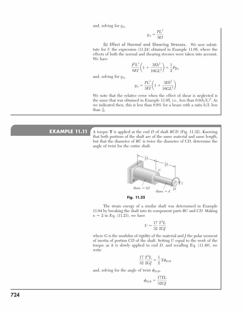
and, solving for y A , y A 5 PL 3 3EI (b) Effect of Normal and Shearing Stresses. We now substi- tute for U the expression (11.24) obtained in Example 11.05, where the effects of both the normal and shearing stresses were taken into account. We have P 2 L 3 6EI a 1 1 3Eh 2 10GL 2 b 5 1 2 Py A and, solving for y A , y A 5 PL 3 3EI a 1 1 3Eh 2 10GL 2 b We note that the relative error when the effect of shear is neglected is the same that was obtained in Example 11.05, i.e., less than 0.9(hyL) 2 . As we indicated then, this is less than 0.9% for a beam with a ratio hyL less than 1 10 . EXAMPLE 11.11 A torque T is applied at the end D of shaft BCD (Fig. 11.32). Knowing that both portions of the shaft are of the same material and same length, but that the diameter of BC is twice the diameter of CD, determine the angle of twist for the entire shaft. Fig. 11.32 1 2 L 1 2 L C D T B diam. 2 d diam. d The strain energy of a similar shaft was determined in Example 11.04 by breaking the shaft into its component parts BC and CD. Making n 5 2 in Eq. (11.23), we have U 5 1 7 32 T 2 L 2GJ where G is the modulus of rigidity of the material and J the polar moment of inertia of portion CD of the shaft. Setting U equal to the work of the torque as it is slowly applied to end D, and recalling Eq. (11.49), we write 1 7 32 T 2 L 2GJ 5 1 2 Tf DyB and, solving for the angle of twist f DyB , f DyB 5 17T L 32GJ 724
-
Upload
khangminh22 -
Category
Documents
-
view
0 -
download
0
Transcript of and, solving for yA, PL3 3EI (b) Effect of Normal and Shearing ...
and, solving for yA,
yA 5PL3
3EI
(b) Effect of Normal and Shearing Stresses. We now substi-tute for U the expression (11.24) obtained in Example 11.05, where the effects of both the normal and shearing stresses were taken into account. We have
P2L3
6EI a1 1
3Eh2
10GL2b 512
PyA
and, solving for yA,
yA 5PL3
3EI a1 1
3Eh2
10GL2bWe note that the relative error when the effect of shear is neglected is the same that was obtained in Example 11.05, i.e., less than 0.9(hyL)2. As we indicated then, this is less than 0.9% for a beam with a ratio hyL less than 1
10.
EXAMPLE 11.11 A torque T is applied at the end D of shaft BCD (Fig. 11.32). Knowing that both portions of the shaft are of the same material and same length, but that the diameter of BC is twice the diameter of CD, determine the angle of twist for the entire shaft.
Fig. 11.32
12 L
12 L
C
D
TB
diam. � 2ddiam. � d
The strain energy of a similar shaft was determined in Example 11.04 by breaking the shaft into its component parts BC and CD. Making n 5 2 in Eq. (11.23), we have
U 51732
T
2L2GJ
where G is the modulus of rigidity of the material and J the polar moment of inertia of portion CD of the shaft. Setting U equal to the work of the torque as it is slowly applied to end D, and recalling Eq. (11.49), we write
1732
T
2L2GJ
512
TfDyB
and, solving for the angle of twist fDyB,
fDyB 517TL32GJ
724
bee80288_ch11_692-758.indd Page 724 11/12/10 5:15:30 PM user-f499 /Users/user-f499/Desktop/Temp Work/Don't Delete Job/MHDQ251:Beer:201/ch11
725
SOLUTION
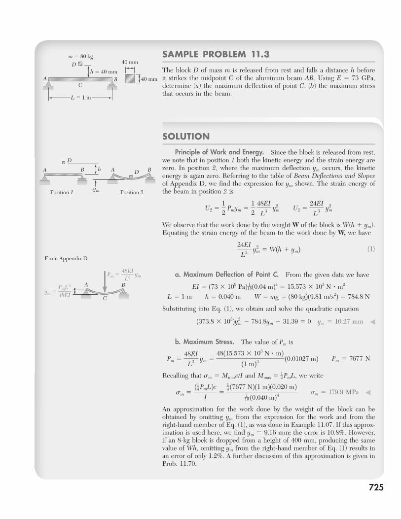
Principle of Work and Energy. Since the block is released from rest, we note that in position 1 both the kinetic energy and the strain energy are zero. In position 2, where the maximum deflection ym occurs, the kinetic energy is again zero. Referring to the table of Beam Deflections and Slopes of Appendix D, we find the expression for ym shown. The strain energy of the beam in position 2 is
U2 512
Pmym 512
48EI
L3 y2m
U2 524EI
L3 y2m
We observe that the work done by the weight W of the block is W(h 1 ym). Equating the strain energy of the beam to the work done by W, we have
24EI
L3 y2m 5 W1h 1 ym2 (1)
a. Maximum Deflection of Point C. From the given data we have
EI 5 173 3 109 Pa2 112 10.04 m24 5 15.573 3 103 N ? m2
L 5 1 m h 5 0.040 m W 5 mg 5 180 kg2 19.81 m/s22 5 784.8 N
Substituting into Eq. (1), we obtain and solve the quadratic equation
1373.8 3 1032y2m 2 784.8ym 2 31.39 5 0 ym 5 10.27 mm ◀
b. Maximum Stress. The value of Pm is
Pm 548EI
L3 ym 548115.573 3 103 N ? m2
11 m23 10.01027 m2
Pm 5 7677 N
Recalling that sm 5 Mmaxc/I and Mmax 5 14 PmL, we write
sm 5
114 PmL2cI
5
14 17677 N2 11 m2 10.020 m2
112 10.040 m24
sm 5 179.9 MPa ◀
An approximation for the work done by the weight of the block can be obtained by omitting ym from the expression for the work and from the right-hand member of Eq. (1), as was done in Example 11.07. If this approx-imation is used here, we find ym 5 9.16 mm; the error is 10.8%. However, if an 8-kg block is dropped from a height of 400 mm, producing the same value of Wh, omitting ym from the right-hand member of Eq. (1) results in an error of only 1.2%. A further discussion of this approximation is given in Prob. 11.70.
SAMPLE PROBLEM 11.3
The block D of mass m is released from rest and falls a distance h before it strikes the midpoint C of the aluminum beam AB. Using E 5 73 GPa, determine (a) the maximum deflection of point C, (b) the maximum stress that occurs in the beam.
A
L � 1 m
B
D
C
m � 80 kg
h � 40 mm
40 mm
40 mm
A
Position 1 Position 2
AB Bh
ym
D
D
A B
C
PmL3
48EIym �
48EIL3Pm � ym
From Appendix D
bee80288_ch11_692-758.indd Page 725 11/19/10 11:34:21 PM user-f499 /Users/user-f499/Desktop/Temp Work/Don't Delete Job/MHDQ251:Beer:201/ch11
726
SOLUTION
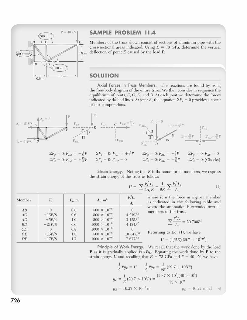
Axial Forces in Truss Members. The reactions are found by using the free-body diagram of the entire truss. We then consider in sequence the equilibrium of joints, E, C, D, and B. At each joint we determine the forces indicated by dashed lines. At joint B, the equation oFx 5 0 provides a check of our computations.
SAMPLE PROBLEM 11.4
Members of the truss shown consist of sections of aluminum pipe with the cross-sectional areas indicated. Using E 5 73 GPa, determine the vertical deflection of point E caused by the load P.
500 mm2
0.8 m
0.6 m1.5 m
P � 40 kN
A C E
B D
500 mm2
1000 mm2
A
B
E 17178
84 5
3
158
1515
EC
DB � 21P/8
Ax � 21P/8
PAy � P
FCE FACFCE �
FCD � 0FAD
FBD
P
FCDFDE
178FDE � P
218FBD �
FAB
P218B � P
B
P
oFy 5 0: FDE 5 2178 P oFx 5 0: FAC 5 115
8 P oFy 5 0: FAD 5 154 P oFy 5 0: FAB 5 0
oFx 5 0: FCE 5 1158 P oFy 5 0: FCD 5 0 oFx 5 0: FBD 5 221
8 P oFx 5 0: 1Checks2 Strain Energy. Noting that E is the same for all members, we express the strain energy of the truss as follows
U 5 a F2
i Li
2Ai E5
12E
a F2i Li
Ai (1)
where Fi is the force in a given member as indicated in the following table and where the summation is extended over all members of the truss.
a Fi2Li
Ai5 29 700P2
Returning to Eq. (1), we have
U 5 11y2E2 129.7 3 103P22. Principle of Work-Energy. We recall that the work done by the load P as it is gradually applied is 1
2 PyE. Equating the work done by P to the strain energy U and recalling that E 5 73 GPa and P 5 40 kN, we have
12
PyE 5 U
12
PyE 51
2E 129.7 3 103P22
yE 51E
129.7 3 103P2 5129.7 3 1032 140 3 1032
73 3 109
yE 5 16.27 3 1023 m yE 5 16.27 mmw ◀
Member Fi Li, m Ai, m2
Fi2Li
Ai
AB 0 0.8 500 3 1026 0 AC 115Py8 0.6 500 3 1026 4 219P2
AD 15Py4 1.0 500 3 1026 3 125P2
BD 221Py8 0.6 1000 3 1026 4 134P2
CD 0 0.8 1000 3 1026 0 CE 115Py8 1.5 500 3 1026 10 547P2
DE 217Py8 1.7 1000 3 1026 7 677P2
bee80288_ch11_692-758.indd Page 726 11/20/10 3:41:35 PM user-f499 /Users/user-f499/Desktop/Temp Work/Don't Delete Job/MHDQ251:Beer:201/ch11
PROBLEMS
727
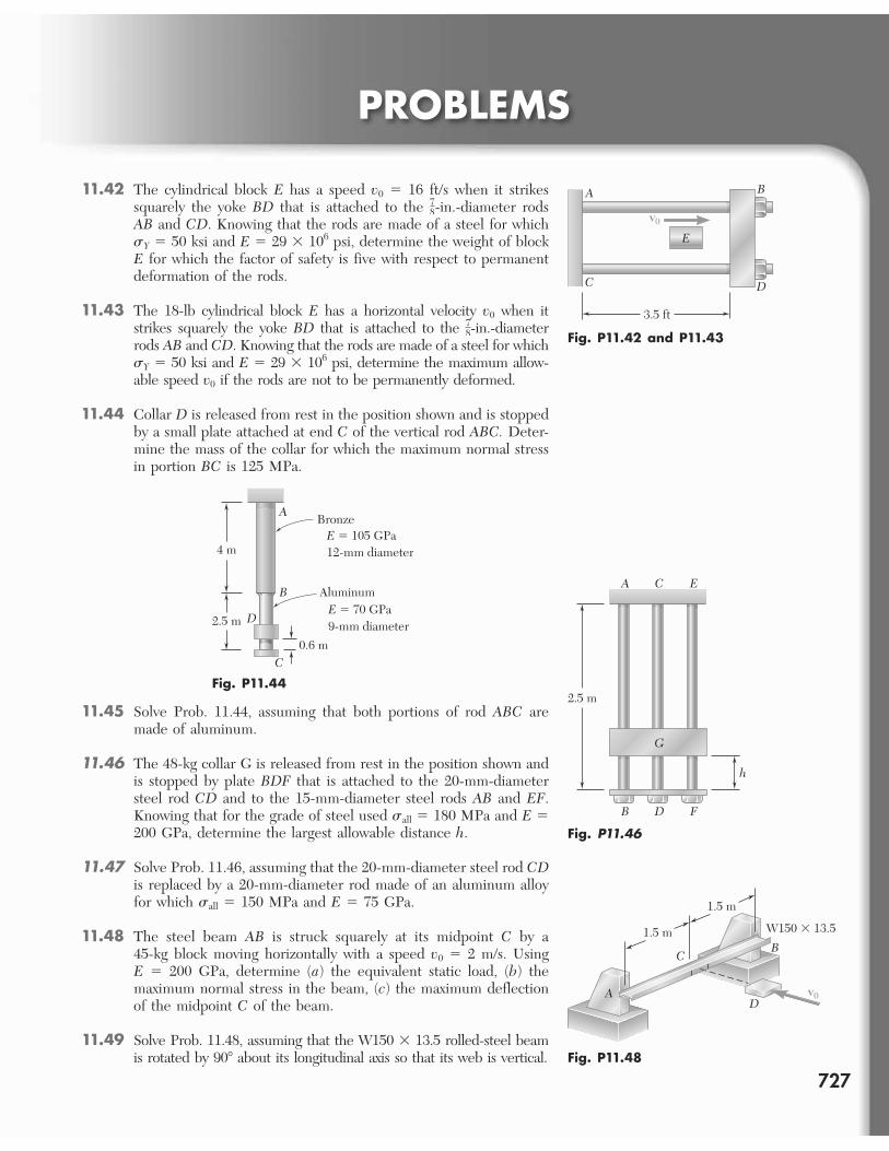
11.42 The cylindrical block E has a speed v0 5 16 ft/s when it strikes squarely the yoke BD that is attached to the 7
8-in.-diameter rods AB and CD. Knowing that the rods are made of a steel for which sY 5 50 ksi and E 5 29 3 106 psi, determine the weight of block E for which the factor of safety is five with respect to permanent deformation of the rods.
11.43 The 18-lb cylindrical block E has a horizontal velocity v0 when it strikes squarely the yoke BD that is attached to the 7
8-in.-diameter rods AB and CD. Knowing that the rods are made of a steel for which sY 5 50 ksi and E 5 29 3 106 psi, determine the maximum allow-able speed v0 if the rods are not to be permanently deformed.
11.44 Collar D is released from rest in the position shown and is stopped by a small plate attached at end C of the vertical rod ABC. Deter-mine the mass of the collar for which the maximum normal stress in portion BC is 125 MPa.
3.5 ft
A
E
B
DC
v0
Fig. P11.42 and P11.43
B
A
C
D
BronzeE � 105 GPa12-mm diameter
AluminumE � 70 GPa9-mm diameter
0.6 m
2.5 m
4 m
Fig. P11.442.5 m
B F
h
D
G
A EC
Fig. P11.46
11.45 Solve Prob. 11.44, assuming that both portions of rod ABC are made of aluminum.
11.46 The 48-kg collar G is released from rest in the position shown and is stopped by plate BDF that is attached to the 20-mm-diameter steel rod CD and to the 15-mm-diameter steel rods AB and EF. Knowing that for the grade of steel used sall 5 180 MPa and E 5200 GPa, determine the largest allowable distance h.
11.47 Solve Prob. 11.46, assuming that the 20-mm-diameter steel rod CDis replaced by a 20-mm-diameter rod made of an aluminum alloy for which sall 5 150 MPa and E 5 75 GPa.
11.48 The steel beam AB is struck squarely at its midpoint C by a 45-kg block moving horizontally with a speed v0 5 2 m/s. Using E 5 200 GPa, determine (a) the equivalent static load, (b) the maximum normal stress in the beam, (c) the maximum deflection of the midpoint C of the beam.
11.49 Solve Prob. 11.48, assuming that the W150 3 13.5 rolled-steel beam is rotated by 908 about its longitudinal axis so that its web is vertical.
1.5 m
A
B
v0D
C
1.5 m
W150 � 13.5
Fig. P11.48
bee80288_ch11_692-758.indd Page 727 11/12/10 5:15:47 PM user-f499 /Users/user-f499/Desktop/Temp Work/Don't Delete Job/MHDQ251:Beer:201/ch11
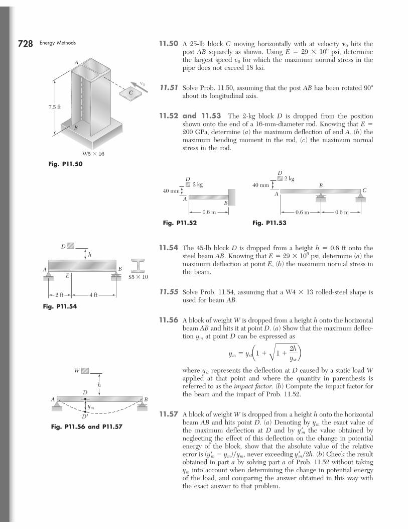
728 Energy Methods 11.50 A 25-lb block C moving horizontally with at velocity v0 hits the post AB squarely as shown. Using E 5 29 3 106 psi, determine the largest speed v0 for which the maximum normal stress in the pipe does not exceed 18 ksi.
11.51 Solve Prob. 11.50, assuming that the post AB has been rotated 908 about its longitudinal axis.
11.52 and 11.53 The 2-kg block D is dropped from the position shown onto the end of a 16-mm-diameter rod. Knowing that E 5 200 GPa, determine (a) the maximum deflection of end A, (b) the maximum bending moment in the rod, (c) the maximum normal stress in the rod.
7.5 ft
A
B
v0
W5 � 16
C
Fig. P11.50
B
D
0.6 m
2 kg40 mm
A
Fig. P11.52
D2 kg
40 mm BCA
0.6 m 0.6 m
Fig. P11.53
11.54 The 45-lb block D is dropped from a height h 5 0.6 ft onto the steel beam AB. Knowing that E 5 29 3 106 psi, determine (a) the maximum deflection at point E, (b) the maximum normal stress in the beam.
11.55 Solve Prob. 11.54, assuming that a W4 3 13 rolled-steel shape is used for beam AB.
11.56 A block of weight W is dropped from a height h onto the horizontal beam AB and hits it at point D. (a) Show that the maximum deflec-tion ym at point D can be expressed as
ym 5 ysta1 1 B1 12hystb
where yst represents the deflection at D caused by a static load W applied at that point and where the quantity in parenthesis is referred to as the impact factor. (b) Compute the impact factor for the beam and the impact of Prob. 11.52.
11.57 A block of weight W is dropped from a height h onto the horizontal beam AB and hits point D. (a) Denoting by ym the exact value of the maximum deflection at D and by y9m the value obtained by neglecting the effect of this deflection on the change in potential energy of the block, show that the absolute value of the relative error is (y9m 2 ym)yym, never exceeding y9my2h. (b) Check the result obtained in part a by solving part a of Prob. 11.52 without taking ym into account when determining the change in potential energy of the load, and comparing the answer obtained in this way with the exact answer to that problem.
BAE
D
S5 � 10
h
2 ft 4 ft
Fig. P11.54
BA
D'
Dh
W
ym
Fig. P11.56 and P11.57
bee80288_ch11_692-758.indd Page 728 11/12/10 5:15:57 PM user-f499 /Users/user-f499/Desktop/Temp Work/Don't Delete Job/MHDQ251:Beer:201/ch11
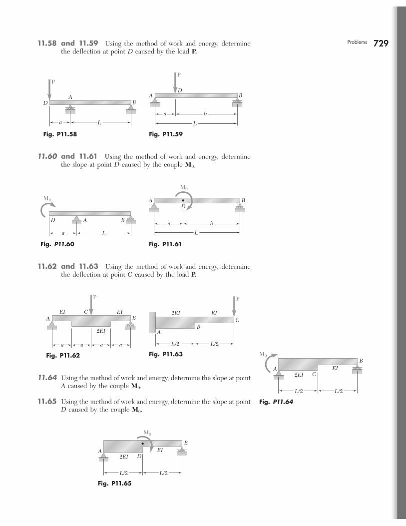
729Problems 11.58 and 11.59 Using the method of work and energy, determine the deflection at point D caused by the load P.
D
a L
BA
P
Fig. P11.58
A
L
a b
BD
P
Fig. P11.59
11.60 and 11.61 Using the method of work and energy, determine the slope at point D caused by the couple M0.
AD
a L
B
M0
Fig. P11.60
M0
A BD
L
a b
Fig. P11.61
11.62 and 11.63 Using the method of work and energy, determine the deflection at point C caused by the load P.
2EI
EI EI
P
A BC
a a a a
Fig. P11.62
BA
L/2
2EI EI
L/2
C
P
Fig. P11.63
11.64 Using the method of work and energy, determine the slope at point A caused by the couple M0.
11.65 Using the method of work and energy, determine the slope at point D caused by the couple M0.
2EIEIA
B
C
L/2L/2
M0
Fig. P11.64
2EIEIA
B
D
L/2L/2
M0
Fig. P11.65
bee80288_ch11_692-758.indd Page 729 11/22/10 7:26:42 PM user-f499 /Users/user-f499/Desktop/Temp Work/Don't Delete Job/MHDQ251:Beer:201/ch11
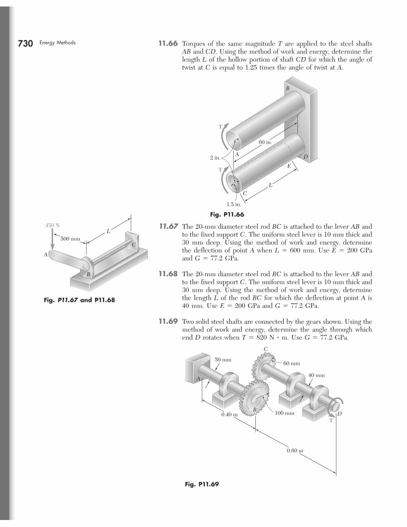
730 Energy Methods 11.66 Torques of the same magnitude T are applied to the steel shafts AB and CD. Using the method of work and energy, determine the length L of the hollow portion of shaft CD for which the angle of twist at C is equal to 1.25 times the angle of twist at A.
60 in.
2 in.
1.5 in.
T
LC
A
ET
B
D
Fig. P11.66
11.67 The 20-mm diameter steel rod BC is attached to the lever AB and to the fixed support C. The uniform steel lever is 10 mm thick and 30 mm deep. Using the method of work and energy, determine the deflection of point A when L 5 600 mm. Use E 5 200 GPa and G 5 77.2 GPa.
11.68 The 20-mm diameter steel rod BC is attached to the lever AB and to the fixed support C. The uniform steel lever is 10 mm thick and 30 mm deep. Using the method of work and energy, determine the length L of the rod BC for which the deflection at point A is 40 mm. Use E 5 200 GPa and G 5 77.2 GPa.
11.69 Two solid steel shafts are connected by the gears shown. Using the method of work and energy, determine the angle through which end D rotates when T 5 820 N ? m. Use G 5 77.2 GPa.
C
A
450 N
B
L500 mm
Fig. P11.67 and P11.68
A
60 mm
100 mm
50 mm
0.60 m
0.40 m D
C
B
T
40 mm
Fig. P11.69
bee80288_ch11_692-758.indd Page 730 11/12/10 5:16:26 PM user-f499 /Users/user-f499/Desktop/Temp Work/Don't Delete Job/MHDQ251:Beer:201/ch11
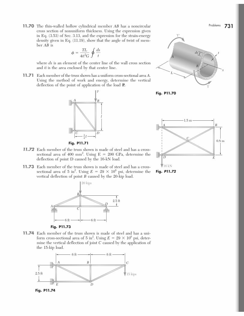
731Problems 11.70 The thin-walled hollow cylindrical member AB has a noncircular cross section of nonuniform thickness. Using the expression given in Eq. (3.53) of Sec. 3.13, and the expression for the strain-energy density given in Eq. (11.19), show that the angle of twist of mem-ber AB is
f 5TL
4A 2G
C dst
where ds is an element of the center line of the wall cross section and A is the area enclosed by that center line.
11.71 Each member of the truss shown has a uniform cross-sectional area A. Using the method of work and energy, determine the vertical deflection of the point of application of the load P.
L
T
T'
A
B
t
x
ds
Fig. P11.70
l34
l
P
DC
BA
Fig. P11.71
11.72 Each member of the truss shown is made of steel and has a cross-sectional area of 400 mm2. Using E 5 200 GPa, determine the deflection of point D caused by the 16-kN load.
11.73 Each member of the truss shown is made of steel and has a cross-sectional area of 5 in2. Using E 5 29 3 106 psi, determine the vertical deflection of point B caused by the 20-kip load.
C
D
16 kN
E
A B1.5 m
0.8 m
Fig. P11.72
6 ft 6 ft
20 kips
2.5 ftD
AC
B
Fig. P11.73
6 ft 6 ft
2.5 ft
A B
DE
C
15 kips
Fig. P11.74
11.74 Each member of the truss shown is made of steel and has a uni-form cross-sectional area of 5 in2. Using E 5 29 3 106 psi, deter-mine the vertical deflection of joint C caused by the application of the 15-kip load.
bee80288_ch11_692-758.indd Page 7 1 11/22/10 7:27:11 PM user-f499 /Users/user-f499/Desktop/Temp Work/Don't Delete Job/MHDQ251:Beer:201/ch11
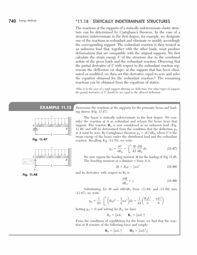
740 Energy Methods *11.14 STATICALLY INDETERMINATE STRUCTURESThe reactions at the supports of a statically indeterminate elastic struc-ture can be determined by Castigliano’s theorem. In the case of a structure indeterminate to the first degree, for example, we designate one of the reactions as redundant and eliminate or modify accordingly the corresponding support. The redundant reaction is then treated as an unknown load that, together with the other loads, must produce deformations that are compatible with the original supports. We first calculate the strain energy U of the structure due to the combined action of the given loads and the redundant reaction. Observing that the partial derivative of U with respect to the redundant reaction rep-resents the deflection (or slope) at the support that has been elimi-nated or modified, we then set this derivative equal to zero and solve the equation obtained for the redundant reaction.† The remaining reactions can be obtained from the equations of statics.
†This is in the case of a rigid support allowing no deflection. For other types of support, the partial derivative of U should be set equal to the allowed deflection.
EXAMPLE 11.15 Determine the reactions at the supports for the prismatic beam and load-ing shown (Fig. 11.47).
The beam is statically indeterminate to the first degree. We con-sider the reaction at A as redundant and release the beam from that support. The reaction RA is now considered as an unknown load (Fig. 11.48) and will be determined from the condition that the deflection yA at A must be zero. By Castigliano’s theorem yA 5 0Uy0RA, where U is the strain energy of the beam under the distributed load and the redundant reaction. Recalling Eq. (11.70), we write
yA 5
0U0RA
5 #L
0
MEI
0M0RA
dx (11.87)
We now express the bending moment M for the loading of Fig. 11.48.The bending moment at a distance x from A is
M 5 RAx 2 12 wx2 (11.88)
and its derivative with respect to RA is
0M0RA
5 x (11.89)
Substituting for M and 0M/0RA from (11.88) and (11.89) into (11.87), we write
yA 51
EI #
L
0
aRAx2 212
wx3b dx 51
EI aRAL3
32
wL4
8b
Setting yA 5 0 and solving for RA, we have
RA 5 38 wL RA 5 3
8 wLx
From the conditions of equilibrium for the beam, we find that the reac-tion at B consists of the following force and couple:
RB 5 58 wLx MB 5 1
8 wL2 i
BA
w
L
Fig. 11.47
RA
yA � 0 BA
w
L
Fig. 11.48
bee80288_ch11_692-758.indd Page 740 11/12/10 5:17:26 PM user-f499 /Users/user-f499/Desktop/Temp Work/Don't Delete Job/MHDQ251:Beer:201/ch11
741
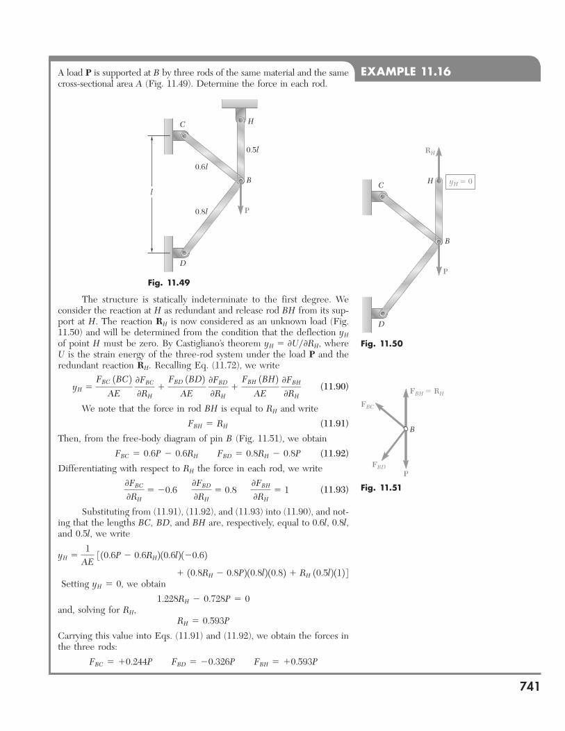
EXAMPLE 11.16A load P is supported at B by three rods of the same material and the same cross-sectional area A (Fig. 11.49). Determine the force in each rod.
Fig. 11.49
H
0.5l
0.6 l
0.8l
C
D
l
P
B HC
D
P
B
RH
yH � 0
Fig. 11.50
B
FBC
FBH � RH
FBDP
Fig. 11.51
The structure is statically indeterminate to the first degree. We consider the reaction at H as redundant and release rod BH from its sup-port at H. The reaction RH is now considered as an unknown load (Fig. 11.50) and will be determined from the condition that the deflection yH of point H must be zero. By Castigliano’s theorem yH 5 0Uy0RH, where U is the strain energy of the three-rod system under the load P and the redundant reaction RH. Recalling Eq. (11.72), we write
yH 5
FBC 1BC2AE
0FBC
0RH1
FBD 1BD2AE
0FBD
0RH1
FBH 1BH2AE
0FBH
0RH (11.90)
We note that the force in rod BH is equal to RH and write
FBH 5 RH (11.91)
Then, from the free-body diagram of pin B (Fig. 11.51), we obtain
FBC 5 0.6P 2 0.6RH FBD 5 0.8RH 2 0.8P (11.92)
Differentiating with respect to RH the force in each rod, we write
0FBC
0RH5 20.6 0FBD
0RH5 0.8 0FBH
0RH5 1 (11.93)
Substituting from (11.91), (11.92), and (11.93) into (11.90), and not-ing that the lengths BC, BD, and BH are, respectively, equal to 0.6l, 0.8l, and 0.5l, we write
yH 51
AE 3 10.6P 2 0.6RH2 10.6l2 120.62
1 10.8RH 2 0.8P2 10.8l2 10.82 1 RH 10.5l2 112 4 Setting yH 5 0, we obtain
1.228RH 2 0.728P 5 0and, solving for RH,
RH 5 0.593P
Carrying this value into Eqs. (11.91) and (11.92), we obtain the forces in the three rods:
FBC 5 10.244P FBD 5 20.326P FBH 5 10.593P
bee80288_ch11_692-758.indd Page 741 11/12/10 5:17:31 PM user-f499 /Users/user-f499/Desktop/Temp Work/Don't Delete Job/MHDQ251:Beer:201/ch11
742
SOLUTION
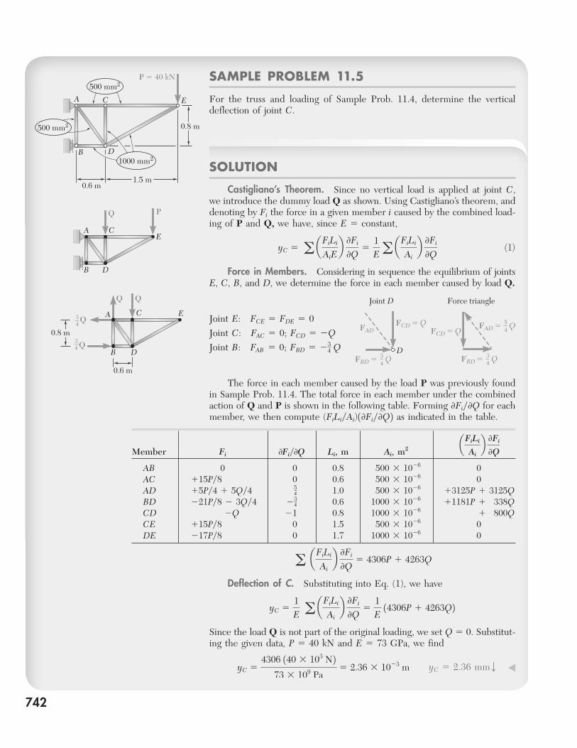
Castigliano’s Theorem. Since no vertical load is applied at joint C, we introduce the dummy load Q as shown. Using Castigliano’s theorem, and denoting by Fi the force in a given member i caused by the combined load-ing of P and Q, we have, since E 5 constant,
yC 5 a aFiLi
AiEb 0Fi
0Q5
1Ea a
FiLi
Aib 0Fi
0Q (1)
Force in Members. Considering in sequence the equilibrium of joints E, C, B, and D, we determine the force in each member caused by load Q.
Joint E: FCE 5 FDE 5 0Joint C: FAC 5 0; FCD 5 2QJoint B: FAB 5 0; FBD 5 23
4 Q
The force in each member caused by the load P was previously found in Sample Prob. 11.4. The total force in each member under the combined action of Q and P is shown in the following table. Forming 0Fiy0Q for each member, we then compute (FiLiyAi)10Fiy0Q2 as indicated in the table.
SAMPLE PROBLEM 11.5
For the truss and loading of Sample Prob. 11.4, determine the vertical deflection of joint C.
a aFiLi
Aib 0Fi
0Q5 4306P 1 4263Q
Deflection of C. Substituting into Eq. (1), we have
yC 51E
a aFiLi
Aib 0Fi
0Q5
1E
14306P 1 4263Q2Since the load Q is not part of the original loading, we set Q 5 0. Substitut-ing the given data, P 5 40 kN and E 5 73 GPa, we find
yC 5
4306 140 3 103 N273 3 109 Pa
5 2.36 3 1023 m
yC 5 2.36 mmw ◀
Member Fi 0Fiy0Q Li, m Ai, m2
aFiLi
Aib 0Fi
0Q
AB 0 0 0.8 500 3 1026 0AC 115Py8 0 0.6 500 3 1026 0AD 15Py4 1 5Qy4 5
4 1.0 500 3 1026 13125P 1 3125QBD 221Py8 2 3Qy4 23
4 0.6 1000 3 1026 11181P 1 338QCD 2Q 21 0.8 1000 3 1026 1 800QCE 115Py8 0 1.5 500 3 1026 0DE 217Py8 0 1.7 1000 3 1026 0
500 mm2
0.8 m
0.6 m1.5 m
P � 40 kN
A C E
B D
500 mm2
1000 mm2
C
Q
A
B D
E
P
A C
0.8 m
Q
Q
34
34
E
B
0.6 m
D
Joint D Force triangle
D
FADFCD � Q
FCD � Q
34FBD � Q 3
4FBD � Q
54FAD � Q
bee80288_ch11_692-758.indd Page 742 11/12/10 5:17:39 PM user-f499 /Users/user-f499/Desktop/Temp Work/Don't Delete Job/MHDQ251:Beer:201/ch11
743
SOLUTION
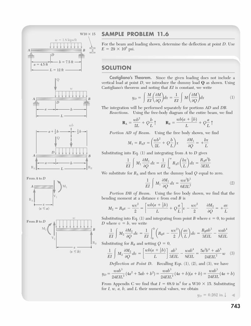
Castigliano’s Theorem. Since the given loading does not include a vertical load at point D, we introduce the dummy load Q as shown. Using Castigliano’s theorem and noting that EI is constant, we write
yD 5 #
MEI
a 0M0Qb dx 5
1EI
# M a 0M0Qb dx (1)
The integration will be performed separately for portions AD and DB. Reactions. Using the free-body diagram of the entire beam, we find
RA 5wb2
2L1 Q
bLx
RB 5
wb1a 1 12 b2
L1 Q
aLx
Portion AD of Beam. Using the free body shown, we find
M1 5 RAx 5 awb2
2L1 Q
bLb x
0M1
0Q5 1
bxL
Substituting into Eq. (1) and integrating from A to D gives
1EI
# M1 0M1
0Q dx 5
1EI
#a
0
RAx abxLb dx 5
RAa3b3EIL
We substitute for RA and then set the dummy load Q equal to zero.
1
EI # M1
0M1
0Q dx 5
wa3b3
6EIL2 (2)
Portion DB of Beam. Using the free body shown, we find that the bending moment at a distance v from end B is
M2 5 RBv 2wv2
25 cwb1a 1 1
2 b2L
1 Q
aLd v 2 wv2
2 0M2
0Q5 1
avL
Substituting into Eq. (1) and integrating from point B where v 5 0, to point D where v 5 b, we write
1EI
# M2 0M2
0Q dv 5
1EI
#b
0
aRBv 2wv2
2b aav
Lb dv 5
RBab3
3EIL2
wab4
8EIL
Substituting for RB and setting Q 5 0,
1
EI # M2
0M2
0Q dv 5 cwb1a 1 1
2 b2L
d ab3
3EIL2
wab4
8EIL5
5a2b4 1 ab5
24EIL2 w (3)
Deflection at Point D. Recalling Eqs. (1), (2), and (3), we have
yD 5wab3
24EIL2 14a2 1 5ab 1 b225 wab3
24EIL2 14a 1 b2 1a 1 b2 5 wab3
24EIL 14a 1 b2
From Appendix C we find that I 5 68.9 in4 for a W10 3 15. Substituting for I, w, a, b, and L their numerical values, we obtain
yD 5 0.262 in.w ◀
SAMPLE PROBLEM 11.6
For the beam and loading shown, determine the deflection at point D. Use E 5 29 3 106 psi.BA
D
L � 12 ft
a � 4.5 ft
w � 1.8 kips/ft
b � 7.5 ft
W10 � 15
BAD
L
a
w
b
Q
BAD
L
a
a � b12
wb
bRA RB
b12
Q
x(x � a)
A
From A to D
M1
RA
V1
wFrom B to D
B
vRB
M2
V2
(v � b)
bee80288_ch11_692-758.indd Page 743 11/12/10 5:17:49 PM user-f499 /Users/user-f499/Desktop/Temp Work/Don't Delete Job/MHDQ251:Beer:201/ch11
744
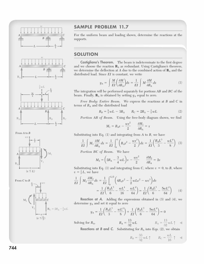
SOLUTION
Castigliano’s Theorem. The beam is indeterminate to the first degree and we choose the reaction RA as redundant. Using Castigliano’s theorem, we determine the deflection at A due to the combined action of RA and the distributed load. Since EI is constant, we write
yA 5 #
MEI
a 0M0RAb dx 5
1EI
# M 0M0RA
dx (1)
The integration will be performed separately for portions AB and BC of the beam. Finally, RA is obtained by setting yA equal to zero.
Free Body: Entire Beam. We express the reactions at B and C in terms of RA and the distributed load
RB 5 94 wL 2 3RA RC 5 2RA 2
34 wL (2)
Portion AB of Beam. Using the free-body diagram shown, we find
M1 5 RAx 2wx2
2 0M1
0RA5 x
Substituting into Eq. (1) and integrating from A to B, we have
1
EI # M1
0M0RA
dx 51
EI #
L
0
aRAx2 2wx3
2b dx 5
1EI
aRAL3
32
wL4
8b (3)
Portion BC of Beam. We have
M2 5 a2RA 234
wLb v 2 wv2
2 0M2
0RA5 2v
Substituting into Eq. (1) and integrating from C, where v 5 0, to B, where v 5 1
2 L, we have
1EI
# M2 0M2
0RA dv 5
1EI
#Ly2
0
a4RAv2 232
wLv2 2 wv3b dv
51
EI aRAL3
62
wL4
162
wL4
64b 5
1EI
aRAL3
62
5wL4
64b
(4)
Reaction at A. Adding the expressions obtained in (3) and (4), we determine yA and set it equal to zero
yA 51
EI aRAL3
32
wL4
8b 1
1EI
aRAL3
62
5wL4
64b 5 0
Solving for RA,
RA 51332
wL
RA 51332
wLx ◀
Reactions at B and C. Substituting for RA into Eqs. (2), we obtain
RB 53332
wLx
RC 5wL16
x ◀
SAMPLE PROBLEM 11.7
For the uniform beam and loading shown, determine the reactions at the supports.
CAB
L L2
w
BA C
LRAL2
w
BA C
L
wL32 L
43L4
L2
RA RB RC
wx
x
A
From A to B
M1
RAV1
x2
(x � L)
(v � )
From C to B
C
v
RC � 2RA �
M2
V2
L2
v2
wv
wL34
bee80288_ch11_692-758.indd Page 744 11/19/10 11:34:35 PM user-f499 /Users/user-f499/Desktop/Temp Work/Don't Delete Job/MHDQ251:Beer:201/ch11
PROBLEMS
745
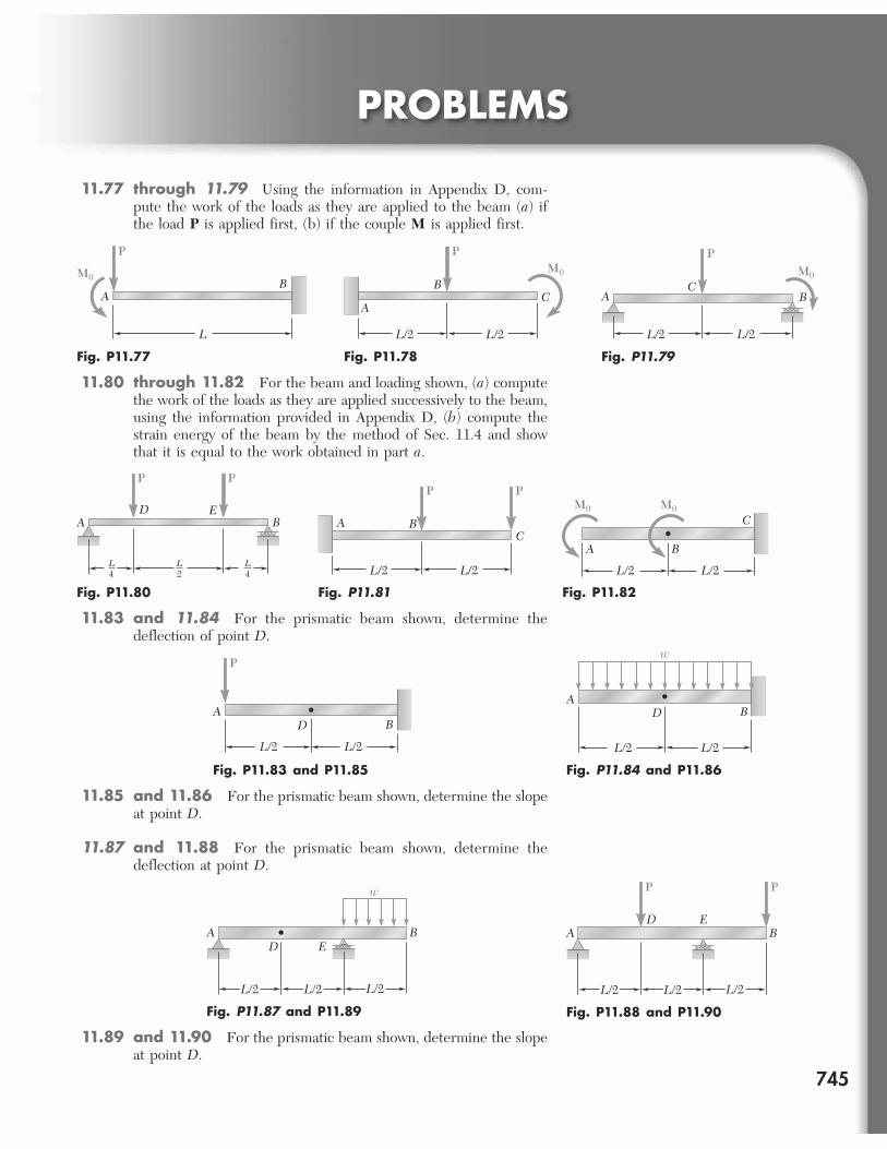
11.77 through 11.79 Using the information in Appendix D, com-pute the work of the loads as they are applied to the beam (a) if the load P is applied first, (b) if the couple M is applied first.
L
BA
M0
P
Fig. P11.77
B
AC
M0
L/2 L/2
P
Fig. P11.78
BAC
PM0
L/2 L/2
Fig. P11.79
11.80 through 11.82 For the beam and loading shown, (a) compute the work of the loads as they are applied successively to the beam, using the information provided in Appendix D, (b) compute the strain energy of the beam by the method of Sec. 11.4 and show that it is equal to the work obtained in part a.
D EBA
L4
L2
L4
P P
Fig. P11.80
BAC
L/2 L/2
PP
Fig. P11.81
C
B
L/2 L/2
A
M0M0
Fig. P11.82
11.83 and 11.84 For the prismatic beam shown, determine the deflection of point D.
BD
L/2 L/2
A
P
Fig. P11.83 and P11.85
11.85 and 11.86 For the prismatic beam shown, determine the slope at point D.
11.87 and 11.88 For the prismatic beam shown, determine the deflection at point D.
L/2 L/2
BA
D
w
Fig. P11.84 and P11.86
11.89 and 11.90 For the prismatic beam shown, determine the slope at point D.
A B
w
D E
L/2 L/2 L/2
Fig. P11.87 and P11.89
A BD E
L/2 L/2 L/2
P P
Fig. P11.88 and P11.90
bee80288_ch11_692-758.indd Page 745 11/12/10 5:18:16 PM user-f499 /Users/user-f499/Desktop/Temp Work/Don't Delete Job/MHDQ251:Beer:201/ch11
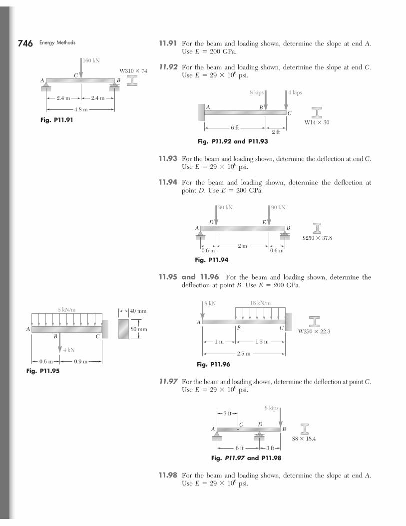
746 Energy Methods 11.91 For the beam and loading shown, determine the slope at end A. Use E 5 200 GPa.
11.92 For the beam and loading shown, determine the slope at end C. Use E 5 29 3 106 psi.
BC
160 kN
A
2.4 m 2.4 m
4.8 m
W310 � 74
Fig. P11.91
BAC
6 ft2 ft
8 kips 4 kips
W14 � 30
Fig. P11.92 and P11.93
11.93 For the beam and loading shown, determine the deflection at end C. Use E 5 29 3 106 psi.
11.94 For the beam and loading shown, determine the deflection at point D. Use E 5 200 GPa.
BAD E
0.6 m
90 kN 90 kN
0.6 m2 m
S250 � 37.8
Fig. P11.94
11.95 and 11.96 For the beam and loading shown, determine the deflection at point B. Use E 5 200 GPa.
ACB
0.6 m 0.9 m
40 mm
80 mm
5 kN/m
4 kN
Fig. P11.95
8 kN
AC
18 kN/m
B
1 m 1.5 m
2.5 m
W250 � 22.3
Fig. P11.96
11.97 For the beam and loading shown, determine the deflection at point C. Use E 5 29 3 106 psi.
BDC
A
8 kips
S8 � 18.4
6 ft 3 ft
3 ft
Fig. P11.97 and P11.98
11.98 For the beam and loading shown, determine the slope at end A. Use E 5 29 3 106 psi.
bee80288_ch11_692-758.indd Page 746 11/15/10 8:06:16 PM user-f499 /Users/user-f499/Desktop/Temp Work/Don't Delete Job/MHDQ251:Beer:201/ch11
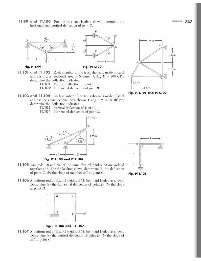
747Problems 11.99 and 11.100 For the truss and loading shown, determine the horizontal and vertical deflection of joint C.
A A
2A DB
C
l lP
l12
Fig. P11.99
l
l
D
B
C12
l12
A
AP
Fig. P11.100
11.101 and 11.102 Each member of the truss shown is made of steel and has a cross-sectional area of 500mm2. Using E 5 200 GPa, determine the deflection indicated.
11.101 Vertical deflection of joint B. 11.102 Horizontal deflection of joint B.
11.103 and 11.104 Each member of the truss shown is made of steel and has the cross-sectional area shown. Using E 5 29 3 106 psi, determine the deflection indicated.
11.103 Vertical deflection of joint C. 11.104 Horizontal deflection of joint C.
2.5 m
1.6 m
1.2 m
1.2 m
4.8 kN
CD
B
A
Fig. P11.101 and P11.102
C
B
4 ft 5 ft
3.75 ft
7.5 kips
4 in2
A
2 in2
6 in2
Fig. P11.103 and P11.104
11.105 Two rods AB and BC of the same flexural rigidity EI are welded together at B. For the loading shown, determine (a) the deflection of point C, (b) the slope of member BC at point C.
11.106 A uniform rod of flexural rigidity EI is bent and loaded as shown. Determine (a) the horizontal deflection of point D, (b) the slope at point D.
C
l
l
B
A
P
Fig. P11.105
C
PD
l
l
A
B
Fig. P11.106 and P11.107
11.107 A uniform rod of flexural rigidity EI is bent and loaded as shown. Determine (a) the vertical deflection of point D, (b) the slope of BC at point C.
bee80288_ch11_692-758.indd Page 747 11/12/10 5:18:52 PM user-f499 /Users/user-f499/Desktop/Temp Work/Don't Delete Job/MHDQ251:Beer:201/ch11
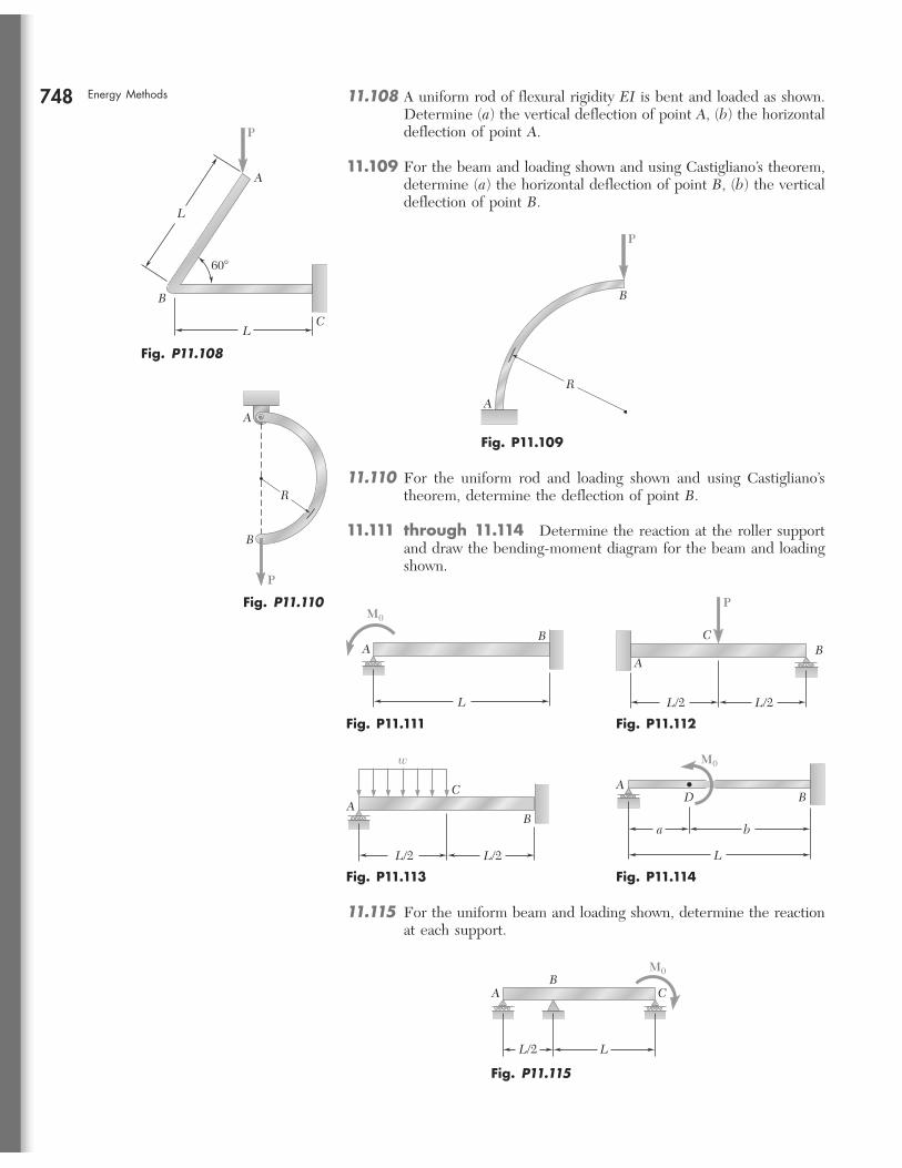
748 Energy Methods 11.108 A uniform rod of flexural rigidity EI is bent and loaded as shown. Determine (a) the vertical deflection of point A, (b) the horizontal deflection of point A.
11.109 For the beam and loading shown and using Castigliano’s theorem, determine (a) the horizontal deflection of point B, (b) the vertical deflection of point B.
L
LC
B
A
60�
P
Fig. P11.108
B
R
A
P
Fig. P11.109
11.110 For the uniform rod and loading shown and using Castigliano’s theorem, determine the deflection of point B.
11.111 through 11.114 Determine the reaction at the roller support and draw the bending-moment diagram for the beam and loading shown.
A
R
B
P
Fig. P11.110
A
M0
B
L
Fig. P11.111
AB
C
P
L/2 L/2
Fig. P11.112
L/2 L/2
BA
C
w
Fig. P11.113
A
L
BD
a b
M0
Fig. P11.114
11.115 For the uniform beam and loading shown, determine the reaction at each support.
M0
L/2 L
AB
C
Fig. P11.115
bee80288_ch11_692-758.indd Page 748 11/12/10 5:19:05 PM user-f499 /Users/user-f499/Desktop/Temp Work/Don't Delete Job/MHDQ251:Beer:201/ch11
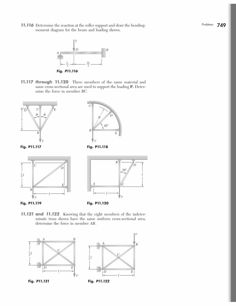
749Problems 11.116 Determine the reaction at the roller support and draw the bending-moment diagram for the beam and loading shown.
BDA
L3
2L3
P
Fig. P11.116
P
l
CD� �
E
B
Fig. P11.117
45�
C
DR
EB
P
Fig. P11.118
DC
34
EB
l
l
P
Fig. P11.119
BD
A C
l
l
30�
P
Fig. P11.120
11.121 and 11.122 Knowing that the eight members of the indeter-minate truss shown have the same uniform cross-sectional area, determine the force in member AB.
Pl
l34
C
ED
A B
Fig. P11.121
P
l34
C
A B
lED
Fig. P11.122
11.117 through 11.120 Three members of the same material and same cross-sectional area are used to support the loading P. Deter-mine the force in member BC.
bee80288_ch11_692-758.indd Page 749 11/19/10 11:34:49 PM user-f499 /Users/user-f499/Desktop/Temp Work/Don't Delete Job/MHDQ251:Beer:201/ch11
754
REVIEW PROBLEMS
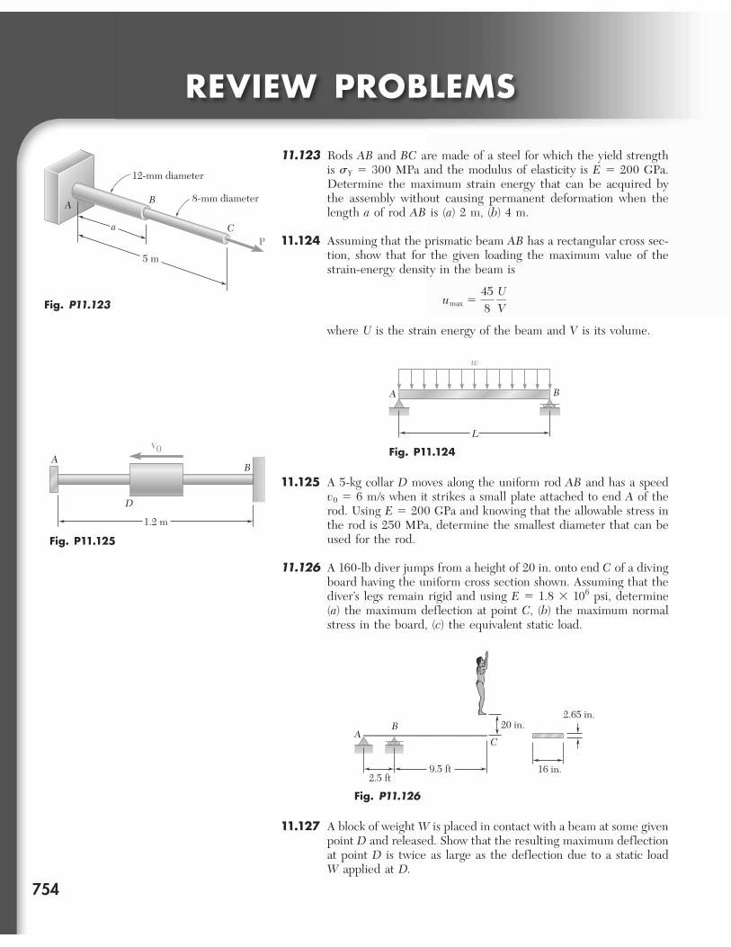
11.123 Rods AB and BC are made of a steel for which the yield strength is sY 5 300 MPa and the modulus of elasticity is E 5 200 GPa. Determine the maximum strain energy that can be acquired by the assembly without causing permanent deformation when the length a of rod AB is (a) 2 m, (b) 4 m.
11.124 Assuming that the prismatic beam AB has a rectangular cross sec-tion, show that for the given loading the maximum value of the strain-energy density in the beam is
umax 5458
UV
where U is the strain energy of the beam and V is its volume.
12-mm diameter
a
5 m
8-mm diameterBA
CP
Fig. P11.123
B
w
A
L
Fig. P11.124
11.125 A 5-kg collar D moves along the uniform rod AB and has a speed v0 5 6 m/s when it strikes a small plate attached to end A of the rod. Using E 5 200 GPa and knowing that the allowable stress in the rod is 250 MPa, determine the smallest diameter that can be used for the rod.
11.126 A 160-lb diver jumps from a height of 20 in. onto end C of a diving board having the uniform cross section shown. Assuming that the diver’s legs remain rigid and using E 5 1.8 3 106 psi, determine (a) the maximum deflection at point C, (b) the maximum normal stress in the board, (c) the equivalent static load.
1.2 m
AV0
B
D
Fig. P11.125
AB
C
2.5 ft9.5 ft 16 in.
2.65 in.20 in.
Fig. P11.126
11.127 A block of weight W is placed in contact with a beam at some given point D and released. Show that the resulting maximum deflection at point D is twice as large as the deflection due to a static load W applied at D.
bee80288_ch11_692-758.indd Page 754 11/12/10 5:20:01 PM user-f499 /Users/user-f499/Desktop/Temp Work/Don't Delete Job/MHDQ251:Beer:201/ch11
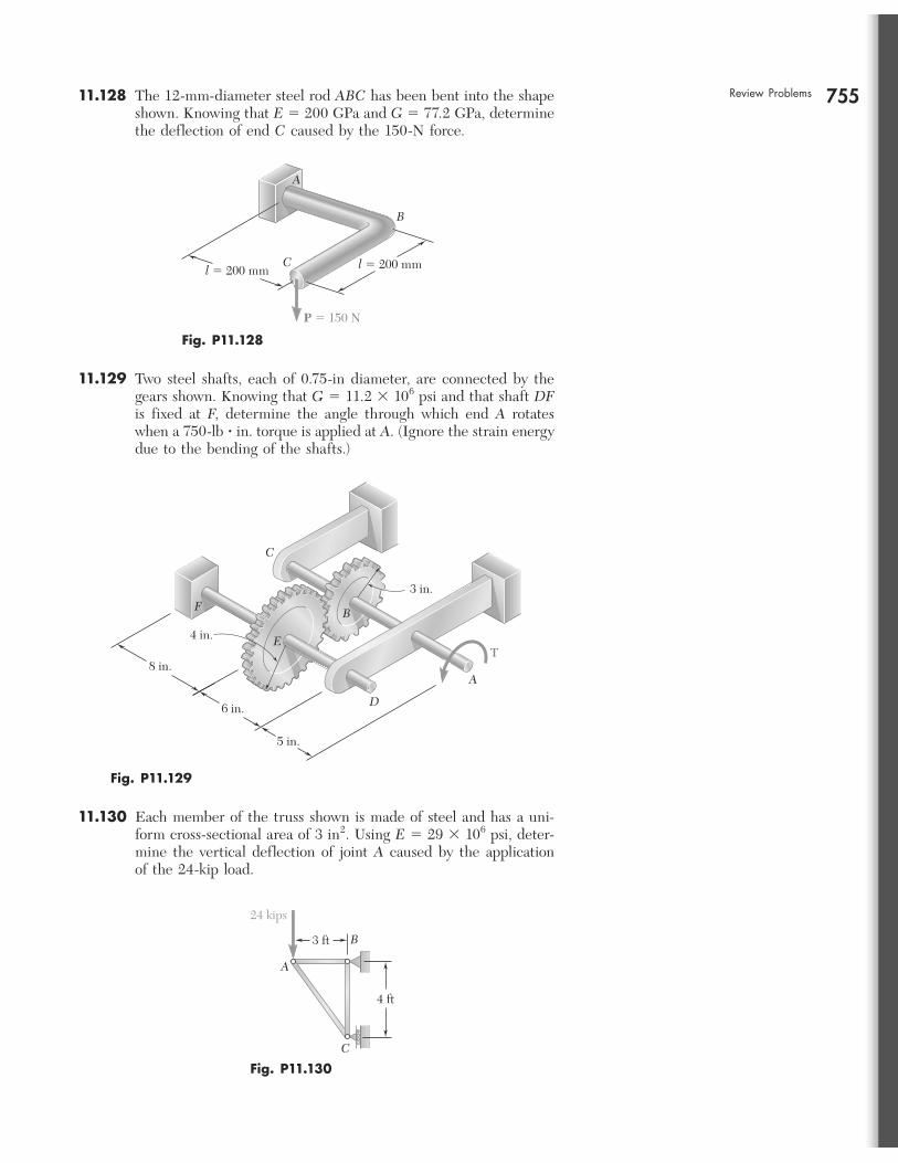
755Review Problems 11.128 The 12-mm-diameter steel rod ABC has been bent into the shape shown. Knowing that E 5 200 GPa and G 5 77.2 GPa, determine the deflection of end C caused by the 150-N force.
l � 200 mm l � 200 mm
P � 150 N
B
C
A
Fig. P11.128
TE
F B
A
3 in.
4 in.
8 in.
6 in.
5 in.
D
C
Fig. P11.129
11.130 Each member of the truss shown is made of steel and has a uni-form cross-sectional area of 3 in2. Using E 5 29 3 106 psi, deter-mine the vertical deflection of joint A caused by the application of the 24-kip load.
24 kips
A
B
4 ft
3 ft
C
Fig. P11.130
11.129 Two steel shafts, each of 0.75-in diameter, are connected by the gears shown. Knowing that G 5 11.2 3 106 psi and that shaft DFis fixed at F, determine the angle through which end A rotates when a 750-lb ? in. torque is applied at A. (Ignore the strain energy due to the bending of the shafts.)
bee80288_ch11_692-758.indd Page 755 11/12/10 5:20:56 PM user-f499 /Users/user-f499/Desktop/Temp Work/Don't Delete Job/MHDQ251:Beer:201/ch11
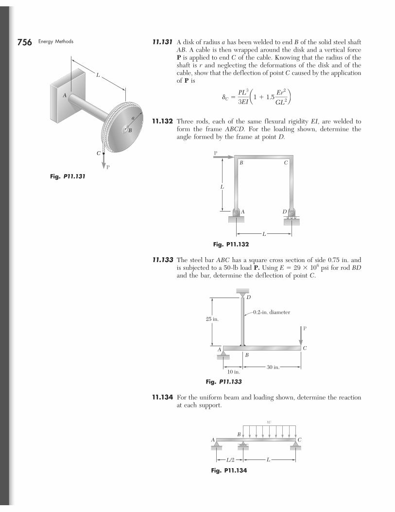
756 Energy Methods 11.131 A disk of radius a has been welded to end B of the solid steel shaft AB. A cable is then wrapped around the disk and a vertical force P is applied to end C of the cable. Knowing that the radius of the shaft is r and neglecting the deformations of the disk and of the cable, show that the deflection of point C caused by the application of P is
dC 5PL3
3EI a1 1 1.5
Er2
GL2b
11.132 Three rods, each of the same flexural rigidity EI, are welded to form the frame ABCD. For the loading shown, determine the angle formed by the frame at point D.
aa
BB
CC
L
P
AA
Fig. P11.131
P
L
L
A D
B C
Fig. P11.132
11.133 The steel bar ABC has a square cross section of side 0.75 in. and is subjected to a 50-lb load P. Using E 5 29 3 106 psi for rod BD and the bar, determine the deflection of point C.
P
D
CB
A
25 in.
10 in.
0.2-in. diameter
30 in.
Fig. P11.133
11.134 For the uniform beam and loading shown, determine the reaction at each support.
BC
w
A
LL/2
Fig. P11.134
bee80288_ch11_692-758.indd Page 756 11/12/10 5:21:08 PM user-f499 /Users/user-f499/Desktop/Temp Work/Don't Delete Job/MHDQ251:Beer:201/ch11