Bifocal contact lenses: History, types, characteristics, and ...
Upload
independentCategory
view
5download
0
1DaTttapfvSTwbdptfzfoIdo
lwefwlststG
Menon et al. Vol. 26, No. 2 /February 2009 /J. Opt. Soc. Am. A 297
Design of diffractive lenses that generate opticalnulls without phase singularities
Rajesh Menon,1,2,* Paul Rogge,3 and Hsin-Yu Tsai4
1Research Laboratory of Electronics, Massachusetts Institute of Technology, Cambridge, Massachusetts 02139, USA2LumArray, Inc., Somerville, Massachusetts 02143, USA
3Department of Mechanical Engineering, University of Nebraska, Lincoln, Nebraska 68588, USA4Department of Electrical Engineering and Computer Science, Massachusetts Institute of Technology, Cambridge,
Massachusetts 02139, USA*Corresponding author: [email protected]
Received June 5, 2008; revised November 20, 2008; accepted November 24, 2008;posted December 5, 2008 (Doc. ID 96953); published January 27, 2009
We exploit a technique, based on nonlinear optimization, to design diffractive lenses that focus optical nullswithout any phase singularities. To ensure ease of fabrication, these lenses are composed of concentric circularzones. Furthermore, we show that this technique is readily extended to multiple wavelengths and can be usedto improve tolerance to fabrication errors. © 2009 Optical Society of America
OCIS codes: 050.1380, 050.1965, 050.1970, 050.5080, 230.3990.
IitaNcfcglm
stdPiaat
2W[zwdpPbpmvcf
. INTRODUCTIONiffractive optics sculpt the propagation of light to gener-te complex intensity and phase patterns downstream [1].hey achieve this by imposing a particular phase and in-ensity pattern on the incident light. Phase-only diffrac-ive optics, as their name implies, affect only the phasend hence are lossless. Binary-phase diffractive optics im-ose only two levels of phase. This significantly eases theabrication of such elements. The phase shift is achievedia an optical-path difference between alternate zones.uch optics inherently exhibit chromatic aberrations.here have been several approaches to design multiple-avelength diffractive optics. A heterogeneous design,ased on materials with differing refractive indices andispersion to compensate for chromatic aberration, wasroposed [2]. By using phase shifts that are integer mul-iples of 2�, harmonic diffractive lenses can be designedor specific discrete wavelengths [3]. A nonlinear optimi-ation technique was used to design dual-wavelength dif-ractive beam splitters [4]. Blazed higher-order diffractiveptics may also be designed for multiple wavelengths [5].n all these cases, the fabrication of the diffractive optic isifficult, either due to the multiple levels of phase heightr due to large aspect ratios.
In this paper, we describe a technique that utilizes non-inear optimization to design lenses that can focus severalavelengths of light into focal spots of distinct geom-tries. In particular, we design a dichromat, a lens thatocuses one wavelength, �1, to a bright spot and a secondavelength, �2, to an overlapping ring-shaped spot. The
atter, with a node in its center, is generated in the ab-ence of any phase singularities. Our primary objective iso fabricate an array of such dichromats to enable paralleluperresolution imaging [6,7]. Focal spots with dark cen-ers are usually generated by focusing Laguerre–aussian modes [8] and higher-order Bessel beams [9,10].
1084-7529/09/020297-8/$15.00 © 2
n both cases, the null arises from the on-axis singularityn the phase of the wavefront. Such singularities mayhemselves be generated using diffractive elements, suchs the spiral-phase plate [11] or the spiral zone plate [12].ot only is the fabrication of such elements quite compli-
ated [13], the resulting phase profile is very sensitive toabrication errors. In this paper, we propose a lens thatan generate a focused optical null without a phase sin-ularity. As opposed to nodes generated via phase singu-arities, we demonstrate that the focal null of the dichro-
at can be made tolerant to fabrication errors.In addition to superresolution imaging, the ring-shaped
pot has important applications in optical tweezers forrapping and manipulating particles whose refractive in-ex is lower than that of the local environment [14,15].hase plates that generate dark spots are also of interest
n optical-projection photolithography [16]. These nullsre useful in astronomy for finding faint planets orbitingstar [17–19]. Dark spots may also have applications in
rapping cold atoms [20].
. DESIGNe follow the technique proposed originally by di Francia
21], where the optic is composed of concentric circularones whose radii are the design variables. In addition,e treat the phase shift between adjacent zones as an ad-itional degree of freedom. This approach was shown toroduce effective superresolving optical elements [22,23].hase-only diffractive lenses with circular symmetry cane readily fabricated in a dielectric material using planarrocesses, enabling large arrays with high optical unifor-ity [24]. As shown in Fig. 1, the phase shift is achieved
ia a height difference between alternate zones. The optican be described by a circular-symmetric transmissionunction
009 Optical Society of America

wmtth
wt
dtc
wotszusc
Ftc ining v
298 J. Opt. Soc. Am. A/Vol. 26, No. 2 /February 2009 Menon et al.
T��� = �ei� r2m � � � r2m+1, m � �0,1,2,3, ... �
0 � � rM
1 elsewhere� , �1�
here � is the radial coordinate, rm is the radius of theth zone, I+ refers to the set of positive integers, and M is
he total number of zones. The relative phase shift be-ween neighboring zones, �, can be related to the zone
ig. 1. (Color online) Schematic of the optic and design methodohe height of the zones, h. Stylized intensity distributions in theuses a bright spot at �1 and a ring-shaped spot at �2. The rema
eight, h, via i
tltl
tcp
� = 2�h
��Re�n���� − 1�, �2�
here Re�n���� is the real part of the refractive index ofhe lens material.
We use the Fresnel–Kirchoff formulation of the scalar-iffraction problem to model the propagation of light fromhe optic to the plane of observation [25]. A normally in-ident uniform plane wave is assumed for simplicity. The
e design parameters are the radii of the zones, r1 ,r2 , . . . ,rM, andplane illustrate the design requirement for a dichromat that fo-ariables are described in the text.
ntensity in the observation plane is then given by
����,z,�,�r�,h�� = 1
i�0
�d�0
2�
dT��,�r�,h��
exp�i2�
���2 + ��2 − 2��� cos�� + z2
��2 + ��2 − 2��� cos�� + z2 �1 +z
��2 + ��2 − 2��� cos�� + z2 2
,
�3�
here � and are the cylindrical coordinates in the planef the diffractive lens, z is the propagation distance alonghe optical axis, and �� is the radial coordinate in the ob-ervation plane. The design variables are the radii of theones, r� = �r1 ,r2 , . . . ,rM�, and the height of the zones, h. Wese the scalar-diffraction theory for its high computationpeed. However, the proposed method is equally appli-able with full-vector diffraction theories. In fact, al-
hough we use the scalar theory to design the diffractiveenses, we use the rigorous full-vector electromagneticheory to verify their focusing performance as describedater.
The key step of the design process is the nonlinear op-imization. The goal of the optimization is to achieve aertain diffraction pattern in the focal, or observation,lane. This goal is described in terms of a fitness function.
logy. Thfocal
Wtf
w�rwodzt
Ttst
ppcctgnwteUgFtdat
Fbshs
Menon et al. Vol. 26, No. 2 /February 2009 /J. Opt. Soc. Am. A 299
e illustrate our method via a dichromat that focuses �1o a round spot and �2 to a ring-shaped spot. The fitnessunction for this design is then expressed as
E��r�,h�� = − w10
�1�����,�1,�r�,h����d��
− w2�2�
�3�����,�2,�r�,h����d��
+ w3���� = 0,�2,�r�,h��, �4�
here �1� is the nominal radius of the round spot at �1 and
2� and �3� are the nominal inner and outer radii of theing-shaped spot at �2; w1, w2, and w3 are positiveeights that allow relative emphasis of one term or an-ther in the fitness function. The last term adjusts theepth of the null in the center of the �2 spot. The optimi-ation algorithm attempts to minimize the fitness func-ion. In addition, the following constraints are imposed:
rp � rq ∀ M � p � q � 1, �p,q� � I, �5�
rp − rp−1 � � � 0 ∀ M � p � 1, p � I, �6�
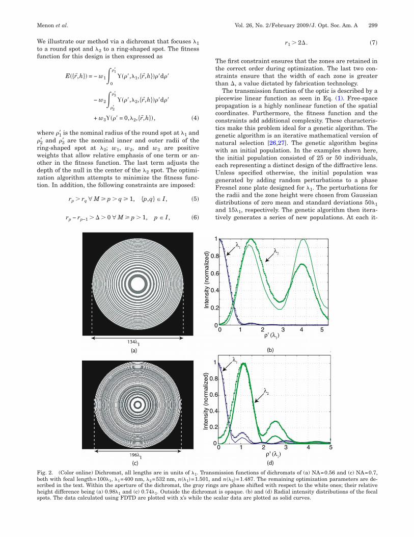
ig. 2. (Color online) Dichromat, all lengths are in units of �1.oth with focal length=100�1, �1=400 nm, �2=532 nm, n��1�=1.cribed in the text. Within the aperture of the dichromat, the graeight difference being (a) 0.98�1 and (c) 0.74�1. Outside the dichpots. The data calculated using FDTD are plotted with x’s whil
r1 � 2�. �7�
he first constraint ensures that the zones are retained inhe correct order during optimization. The last two con-traints ensure that the width of each zone is greaterhan �, a value dictated by fabrication technology.
The transmission function of the optic is described by aiecewise linear function as seen in Eq. (1). Free-spaceropagation is a highly nonlinear function of the spatialoordinates. Furthermore, the fitness function and theonstraints add additional complexity. These characteris-ics make this problem ideal for a genetic algorithm. Theenetic algorithm is an iterative mathematical version ofatural selection [26,27]. The genetic algorithm beginsith an initial population. In the examples shown here,
he initial population consisted of 25 or 50 individuals,ach representing a distinct design of the diffractive lens.nless specified otherwise, the initial population was
enerated by adding random perturbations to a phaseresnel zone plate designed for �1. The perturbations forhe radii and the zone height were chosen from Gaussianistributions of zero mean and standard deviations 50�1nd 15�1, respectively. The genetic algorithm then itera-ively generates a series of new populations. At each it-
ission functions of dichromats of (a) NA=0.56 and (c) NA=0.7,d n��2�=1.487. The remaining optimization parameters are de-
s are phase shifted with respect to the white ones; their relativeis opaque. (b) and (d) Radial intensity distributions of the focal
calar data are plotted as solid curves.
Transm501, any ringromat
e the s
eiatgttcabp(2
3LTdcT==
sTs1dttbnwmtt
gFht2tffi
300 J. Opt. Soc. Am. A/Vol. 26, No. 2 /February 2009 Menon et al.
ration, every individual is ranked based on the value ofts fitness function. The individuals for the next iterationre generated by retaining those in the current genera-ion with the lowest fitness values, by randomly selectingenes (the design variables) from pairs of individuals inhe current generation, and by adding random perturba-ions to the genes of randomly selected individuals in theurrent generation. At each iteration, the individuals arelso forced to satisfy all the linear constraints andounds. This iterative process is continued until a stop-ing criterion is met. In all the examples discussed hereunless specified otherwise), the algorithm stopped after5 generations.
. DICHROMAT: A TWO WAVELENGTHENShe technique described above was used to design twoichromats each with a focal length of 100�1, and numeri-al aperture, NA=0.56 (40 zones) and NA=0.7 (80 zones).he design wavelengths were �1=400 nm and �2532 nm. The optimization was carried out with �1�
�1 /NA, �2�=�2 /NA, and �3�=2�2 /NA. The lens was as- cumed to be made of polymethylmethacrylate (PMMA).he refractive indices of PMMA as measured using apectroscopic ellipsometer were 1.501 at �1=400 nm and.487 at �2=532 nm; � was set to �1 for the 40-zoneichromat and to 0.5�1 for the 80-zone dichromat. Sincehe initial population was generated via slight variationso a phase zone plate at �1, the weight w2 was chosen toe ten times w1. The higher the weight, w3, the darker theull at �2. However, it should not be so large as to over-helm the other terms in the fitness function. We deter-ined empirically that w3=104 w1 was appropriate for
he cases described in this paper. The weight, w1, was seto 1.
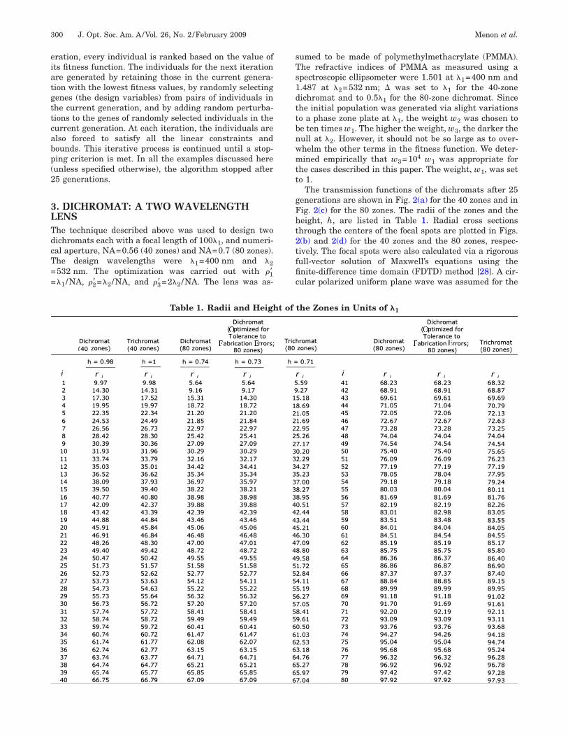
The transmission functions of the dichromats after 25enerations are shown in Fig. 2(a) for the 40 zones and inig. 2(c) for the 80 zones. The radii of the zones and theeight, h, are listed in Table 1. Radial cross sectionshrough the centers of the focal spots are plotted in Figs.(b) and 2(d) for the 40 zones and the 80 zones, respec-ively. The focal spots were also calculated via a rigorousull-vector solution of Maxwell’s equations using thenite-difference time domain (FDTD) method [28]. A cir-
ular polarized uniform plane wave was assumed for theTable 1. Radii and Height of the Zones in Units of �1

Fufidawtdopifc
ATtfisooiccttifddm
BAptds
tdh
wm�wotT
Tcc�Fif=n
Ft
Menon et al. Vol. 26, No. 2 /February 2009 /J. Opt. Soc. Am. A 301
DTD simulations. Although the design was performedsing the scalar theory, the full-vector simulations con-rm that the technique was successful in designing aichromat that focuses �1 to a round bright spot and �2 toring-shaped spot. The FDTD data are plotted with x’shile the scalar data is plotted with solid curves. Al-
hough features on the order of 0.5�1 are present in theichromats, the scalar theory predicts the general shapef the focal spots quite well. Finally, since the optic is com-osed of concentric circular zones, no phase singularity ismposed on the focused wavefront. The focal node at �2 isormed as a result of destructive interference from theoncentric zones.
. Defocushe focusing characteristics of the dichromat change ashe observation plane is swept through the focus. This de-nes the useful depth-of-focus of the lens. Figure 3(a)hows the focused spots calculated using FDTD for vari-us values of z. The ring at �2 is well-defined for a rangef approximately �1 /2. Figure 3(b) shows the correspond-ng data for �1. It was noticed that the intensity in theentral node at �2 increases rapidly with defocus. This isharacteristic of destructive interference from the mul-iple zones. When the appropriate path-difference condi-ion is not met, there is no destructive interference. Thiss problematic for patterning, where a large depth-of-ocus is desired. However, it can be very useful for three-imensional imaging, where a three-dimensional node isesired, such as in stimulated emission depletion (STED)icroscopy [29].
. Tolerance to Fabrication Errorsssuming that the dichromat would be fabricated usinglanar processes, it is important to understand the sensi-ivity of the focusing characteristics to errors introduceduring fabrication. Fabrication errors manifest them-elves as errors in the radii of the zones and the height of
focus - 0.5λ1focus - λ1
10λ1
10λ1
ig. 3. Intensity distributions calculated using FDTD of the dichhe dichromat for (a) � and (b) � .
1 2he zones. Their effect can be simulated by adding ran-omly generated errors to the zone radii and the phaseeight
r� = �r1,r2, . . . ,rM� → r�̃ = �r1 + r1˜,r2 + r2
˜, . . . ,rM + rM˜�,
�8�
h → h̃ = h + h˜, �9�
here rp˜ and h̃ are randomly generated from two nor-
al distributions of zero mean and standard deviations,r and �h, respectively. To quantify the effect of the error,e calculated the distribution of the focusing efficienciesf the error-prone dichromats at the two wavelengths andhen calculated their corresponding standard deviations.he focusing efficiencies are defined as:
�1��r�,h�� =
0
�1�����,�1,�r�,h����d��
0
����,�1,�r�,h����d��
, �10�
�2��r�,h�� =
�2�
�3�����,�2,�r�,h����d��
0
����,�2,�r�,h����d��
. �11�
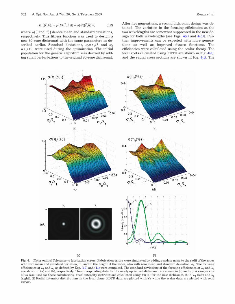
he robustness of the dichromat was investigated by cal-ulating the standard deviations of the focusing efficien-ies, ���1��r�̃ , h̃��� and ���2��r�̃ , h̃���, as a function of �r andh. The results for the original dichromat are shown inigs. 4(a) and 4(b). It is seen that the variations in �1 and
n �2 are below 1% and 4%, respectively, even for largeabrication errors (�r=0.4�1=160 nm and �h=0.04�116 nm). To design a more robust dichromat, we defined aew fitness function as follows:
s focus + 0.5λ1 focus + λ1
)
)
shown in Fig. 2(c) at various transverse planes near the focus of
focu
(a
(b
romat
wrns=pi
Attsttefa
Fweao(c
302 J. Opt. Soc. Am. A/Vol. 26, No. 2 /February 2009 Menon et al.
Er��r�,h�� = ��E��r�̃,h̃��� + ��E��r�̃,h̃���, �12�
here �� � and �� � denote mean and standard deviations,espectively. This fitness function was used to design aew 80-zone dichromat with the same parameters as de-cribed earlier. Standard deviations, �r=�1 /8 and �h�1 /40, were used during the optimization. The initialopulation for the genetic algorithm was derived by add-ng small perturbations to the original 80-zone dichromat.
fter five generations, a second dichromat design was ob-ained. The variation in the focusing efficiencies at thewo wavelengths are somewhat suppressed in the new de-ign for both wavelengths [see Figs. 4(c) and 4(d)]. Fur-her improvements can be expected with more genera-ions as well as improved fitness functions. Thefficiencies were calculated using the scalar theory. Theocal spots calculated using FDTD are shown in Fig. 4(e),nd the radial cross sections are shown in Fig. 4(f). The
ig. 4. (Color online) Tolerance to fabrication errors. Fabrication errors were simulated by adding random noise to the radii of the zonesith zero mean and standard deviation, �r, and to the height of the zones, also with zero mean and standard deviation, �h. The focusing
fficiencies at �1 and �2 as defined by Eqs. (10) and (11) were computed. The standard deviations of the focusing efficiencies at �1 and �2re shown in (a) and (b), respectively. The corresponding data for the newly optimized dichromat are shown in (c) and (d). A sample sizef 25 was used for these calculations. Focal intensity distributions calculated using FDTD for the new dichromat at (e) �1 (left) and �2right). (f) Radial intensity distributions in the focal plane. FDTD data are plotted with x’s while the scalar data are plotted with solidurves.

Fpa
4Tttsn
wwfwsfwc
otghcltslc
Fcwaw
Menon et al. Vol. 26, No. 2 /February 2009 /J. Opt. Soc. Am. A 303
DTD data are plotted using x’s while the scalar data islotted using solid curves. A list of the radii of the zonesnd the height h is in Table 1.
. ADDING A THIRD WAVELENGTHhe proposed technique is readily extended to more thanwo wavelengths. We demonstrate this by designing arichromat, a lens that can focus �1 and �3 into brightpots while �2 is focused into a ring-shaped spot. The fit-ess function is modified as follows:
E��r�,h�� = − w10
�1�����,�1,�r�,h����d��
− w2�2�
�3�����,�2,�r�,h����d�� + w3����
= 0,�2,�r�,h�� − w40
�4�����,�3,�r�,h����d��,
�13�
here �4� is the desired spot radius for �3 and w4 is theeight that emphasizes focusing at �3. The parameters
or the optimization were �3=633 nm, �4�=�3 /NA, and4=10. The refractive index of PMMA at �3 was mea-
ured as 1.4812. All other parameters were the same asor the dichromats. In each case, the initial populationas generated by applying random perturbations to the
orresponding dichromat shown in Fig. 2.Figures 5(a) and 5(c) show the transmission functions
f the trichromats with 40 zones and 80 zones, respec-ively. Satisfactory solutions were obtained after only fiveenerations. A list of the radii of the zones and the height,, is in Table 1. Figures 5(b) and 5(d) show the radialross sections through the focal plane for the three wave-engths. Again, the FDTD data are plotted using x’s whilehe scalar data is plotted using solid curves. Note that thecalar data diverges from the FDTD data at longer wave-engths, as expected. The proposed technique can, in prin-iple, be extended to an arbitrary number of discrete
ig. 5. (Color online) Transmission function of a trichromat, a lens that focuses �1 and �3 to bright spots and �2 to a ring-shaped spotontaining (a) 40 zones and (c) 80 zones. The parameters of the trichromat were �3=633 nm, and n��3�=1.482. The remaining parametersere the same as for the corresponding dichromat. The height difference between the gray and white zones is (a) �1 and (c) 0.6101�1. (b)nd(d) Intensity distributions in the focal plane for the trichromats with 40 and 80 zones, respectively. FDTD data are plotted using x’shile the scalar data are plotted using solid curves.

wd
5Ienlbttnpflel
AWfwPCgSpp
R
1
1
1
1
1
1
1
1
1
1
2
2
2
2
2
2
2
2
2
2
304 J. Opt. Soc. Am. A/Vol. 26, No. 2 /February 2009 Menon et al.
avelengths with the flexibility of being able to specifyifferent focal distributions at each design wavelength.
. CONCLUSIONSn this paper, we described a technique based on nonlin-ar optimization using genetic algorithms to design bi-ary phase-only diffractive optics for multiple wave-
engths. We demonstrated the efficacy of this techniquey designing a dichromat, a lens that focuses �1 to a cen-ral bright spot, and �2 to a ring-shaped spot with a cen-ral null. As opposed to conventional methods, the focalull of the dichromat is formed in the absence of anyhase singularities. We show that the design technique isexible enough to incorporate robustness to fabricationrrors and is readily extended to more than two wave-engths.
CKNOWLEDGMENTSe are grateful to Henry Smith and George Barbastathis
or critical comments. We thank Will Arora for assistanceith the measurement of the refractive indices of PMMA.. Rogge was funded by the MIT Materials Processingenter and the MIT Center for Materials Science and En-ineering for a summer internship through the Nationalcience Foundation (NSF) REU program. H.-Y. Tsai wasartially funded by an ignition grant from the MIT Desh-ande Center for Technological Innovation.
EFERENCES1. B. Kress and P. Meyrueis, Digital Diffractive Optics: An
Introduction to Planar Diffractive Optics and RelatedTechnology (Wiley, 2000).
2. Y. Arieli, S. Noach, S. Ozeri, and N. Eisenberg, “Design ofdiffractive optical elements for multiple wavelengths,”Appl. Opt. 37, 6174–6177 (1998).
3. D. W. Sweeney and G. E. Sommargren, “Harmonicdiffractive lenses,” Appl. Opt. 34, 2469–2475 (1995).
4. S. Zhou, P. Yeh, and R. Nabiev, “Optimal design of dual-wavelength multiple beam splitters,” Opt. Lett. 20,109–111 (1995).
5. D. Faklis and G. M. Morris, “Spectral properties ofmultiorder diffractive lenses,” Appl. Opt. 34, 2462–2468(1995).
6. V. Westphal and S. W. Hell, “Nanoscale resolution in thefocal plane of an optical microscope,” Phys. Rev. Lett. 94,143903 (2005).
7. R. Menon, H.-Y. Tsai, and S. W. Thomas, “Far-fieldgeneration of localized light fields using far-field optics viaabsorbance modulation,” Phys. Rev. Lett. 98, 043905(2007).
8. M. P. MacDonald, L. Paterson, G. Armstrong, A. J. Bryant,W. Sibbett, and K. Dholakia, “Laguerre–gaussian lasermodes for biophotonics and micromanipulation,” Proc.
SPIE 5147, 48–59 (2003).9. A. Vasara, J. Turunen, and A. T. Friberg, “Realization ofgeneral nondiffracting beams with computer-generatedholograms,” J. Opt. Soc. Am. A 6, 1748–1754 (1989).
0. C. Paterson and R. Smith, “Higher-order bessel wavesproduced by axicon-type computer-generated holograms,”Opt. Commun. 124, 121–130 (1996).
1. T. Watanabe, T. Watanabe, M. Fujii, Y. Watanabe, N.Toyoma, and Y. Iketaki, “Generation of a doughnut-shapedbeam with a spiral phase plate,” Rev. Sci. Instrum. 75,5131–5135 (2004).
2. J. A. O. Huguenin, B. C. dos Santos, P. A. M. dos Santos,and A. Z. Khoury, “Topological defects in moiré fringes withspiral zone plates,” J. Opt. Soc. Am. A 20, 1883–1889(2003).
3. H.-Y. Tsai, H. I. Smith, and R. Menon, “Fabrication ofspiral-phase diffractive elements using scanning-electron-beam lithography,” J. Vac. Sci. Technol. B 25, 2068–2071(2007).
4. J. Arlt and M. J. Padgett, “Generation of a beam with adark focus surrounded by regions of higher intensity: theoptical bottle beam,” Opt. Lett. 25, 191–193 (2000).
5. K. T. Gahagan and G. A. Schwartzlander, Jr., “Opticalvortex trapping of particles,” Opt. Lett. 21, 827–829 (1996).
6. M. D. Levenson, T. Ebihara, G. Dai, Y. Morikawa, N.Hayashi, and S. M. Tan, “Optical vortex masks for vialevels,” J. Microlithogr., Microfabr., Microsyst. 3, 293–304(2004).
7. A. Tavrov, R. Bohr, M. Totzeck, H. Tiziani, and M. Takeda,“Achromatic nulling interferometer based on a geometricspin-redirection phase,” Opt. Lett. 27, 2070–2072 (2002).
8. E. Serabyn, J. K. Wallace, G. J. Hardy, E. G. H. Schmidtlin,and H. T. Nguyen, “Deep nulling of visible laser light,”Appl. Opt. 38, 7128–7132 (1999).
9. E. Serabyn and M. M. Colavita, “Fully symmetric nullingbeam combiners,” Appl. Opt. 40, 1668–1671 (2001).
0. R. Ozeri, L. Khaykovich, and N. Davidson, “Long spinrelaxation times in a single-beam blue-detuned opticaltrap,” Phys. Rev. A 59, R1750–R1753 (1999).
1. G. T. di Francia, “Supergain antennas and optical resolvingpower,” Nuovo Cimento, Suppl. 9, 426–438 (1952).
2. C. J. R. Sheppard, G. Calvert, and M. Wheatland, “Focaldistribution for superresolving toraldo filters,” J. Opt. Soc.Am. A 15, 849–856 (1998).
3. T. R. M. Sales and G. M. Morris, “Diffractivesuperresolution elements,” J. Opt. Soc. Am. A 14,1637–1646 (1997).
4. D. Gil, R. Menon, and H. I. Smith, “Fabrication of high-numerical aperture phase zone plates with a singlelithgraphy step and no etching,” J. Vac. Sci. Technol. B 21,2956–2960 (2003).
5. J. W. Goodman, An Introduction to Fourier Optics(McGraw-Hill, 1996), Chap. 4.
6. M. Mitchell, An Introduction to Genetic Algorithms (MITPress, 1996).
7. The genetic algorithm was implemented using the GeneticAlgorithm and Direct Search toolbox in MATLAB.Documentation available at http:www.mathworks.com/access/helpdesk/help/toolbox/gads/.
8. D. W. Prather and S. Shi, “Formulation and application ofthe finite-difference time-domain method for the analysis ofaxially symmetric diffractive optical elements,” J. Opt. Soc.Am. A 16, 1131–1142 (1999).
9. M. Dyba and S. W. Hell, “Focal spots of size � /23 open upfar-field fluorescence microscopy at 33 nm axial resolution,”
Phys. Rev. Lett. 88, 163901 (2002).Copyright © 2022 FDOKUMEN