
Exploring the ``Double-Edged Sword'' Effect of Auto-Insight ...
Upload
independentCategory
view
1download
0
Edge profile of commercially availablesquare-edged intraocular lenses
Mayank A. Nanavaty, DO, David J. Spalton, FRCS, FRCP, FRCOphth,James Boyce, PhD, Anthony Brain, PhD, John Marshall, PhD
PURPOSE: To analyze the sharpness of the posterior optic edge profile and edge thickness ofintraocular lenses (IOLs) marketed with a square-edged profile.
SETTING: Department of Ophthalmology, St. Thomas’ Hospital, London, United Kingdom.
METHODS: Seventeen square-edged 20.0 diopter IOLs of different manufacture, design, and materialwere selected. After the environmental scanning electron microscopy technique was standardized,repeatability of the technique was tested. Posterior optic edges of all IOLs were scanned at a magni-fication of �500. Local radii of curvature of the posterior optic edges were measured by purpose-designed software. Optic edge thickness was also measured from the electron micrographs.
RESULTS: The repeatability of the scanning technique was excellent (G0.10 mm). The radius ofcurvature of posterior optic edges ranged from 7.6 to 23.1 mm. Hydrophilic acrylic IOLs (exceptthe HumanOptics MC Microlens 611 MI-B and 1CU) had radii of curvatures more than 10.0 mmof the posterior optic edge compared with hydrophobic acrylic and silicone IOLs (<10.0 mm) exceptthe Hoya AF-1 (19.9 mm). Alcon AcrySof single-piece (SN60WF), HumanOptics 1CU, and AMO Clar-iflex CLRFLXC IOLs had the thinnest optic edges in the hydrophobic, hydrophilic, and siliconegroups, respectively.
CONCLUSIONS: Commercially marketed square-edged IOLs differed in the sharpness of the poste-rior optic edge. Hydrophobic acrylic and silicone IOLs have sharper posterior optic square edge thanmost hydrophilic acrylic IOLs. This probably reflects difference in manufacturing techniques. Differ-ences in posterior optic edge profile may explain variation in posterior capsule opacification perfor-mance with different IOLs and materials.
J Cataract Refract Surg 2008; 34:677–686 Q 2008 ASCRS and ESCRS
LABORATORY SCIENCE
Posterior capsule opacification (PCO) remains themain complication of cataract surgery. Its develop-ment is multifactorial, involving patient factors, surgi-cal technique,1–3 intraocular lens (IOL) design, andpossibly IOL biomaterial.4–8
Clinical studies show that IOLs with a square-edged optic profile are associated with less PCOthan those with a round-edged profile.9–14 Nishiand Nishi10 suggest this is because a square-edgedIOL optic produces a sharp bend in the posteriorcapsule. When migrating lens epithelial cells (LECs)meet this sharp, discontinuous bend, they are subjectto contact inhibition and stop proliferating and mi-grating (the contact inhibition theory).6,7 In contrast,a round-edged IOL optic produces a more curved,non-sharp continuous bend that does not inducecontact inhibition. Bhermi et al.15 suggest an alterna-tive hypothesis whereby the square edge producesan increased pressure profile at the point on the
Q 2008 ASCRS and ESCRS
Published by Elsevier Inc.
posterior capsule where the posterior edge is com-pressed against the posterior capsule; this createsa physical pressure barrier to LEC migration (thecapsule compression theory). Most manufacturersnow produce square-edged IOLs; however, it has be-come apparent that there are variations in PCO pre-vention between them. Moreover, there is littleevidence of how sharp the optic edge must be to ef-fectively prevent LEC migration. Tetz and Wildeck,14
using different edge designs with a poly(methylmethacrylate) (PMMA) block in cell culture, showedthat sharper optic edges more effectively preventedthe migration of LECs.
This studywas designed to evaluate the edge profileof several commercially available IOLs using scanningelectron microscopy (SEM). All IOLs are marketed ashaving a ‘‘square-edged’’ profile. Using purpose-designed software, we measured the IOLs’ edgesharpness and edge thickness.
0886-3350/08/$dsee front matter 677doi:10.1016/j.jcrs.2007.12.024

678 LABORATORY SCIENCE: EDGE PROFILE OF SQUARE-EDGED IOLS
MATERIALS AND METHODS
Seventeen IOLs of different design and material wereselected from prominent European manufacturers. A 20.0diopter (D) IOL from each manufacturer was used in thestudy. The IOLs were mounted and scanned using a Quanta200F field emission gun environmental scanning electronmicroscope (ESEM) (FEI Co.). Each IOL was processedindividually.
In brief, the IOLs were carefully mounted by an experi-enced electron microscopist using a simple microscope ona platform with a central groove. A pill of black carbonwax (Apiezon Q, Apiezon Products) was plastered in thecenter of the groove on the platform. The IOL was then slot-ted in the groove and the wax so that 1 end of the IOL opticstood vertically embedded in the wax pill and the other endprotruded beyond the platform edge (Figure 1). Some IOLs,such as the Bausch & Lomb Akreos, Bausch & Lomb AkreosAO, HumanOptics 1CU, and Lenstec Tetraflex, required cut-ting of the haptic for stable mounting to obtain the best scansof the IOL optic edge. Utmost care was taken to identify theanterior and posterior optic edges before the IOLs weremounted so that the posterior optic edge appeared left onthe scan.
Figure 1. Intraocular lens mounted before scanning.
Accepted for publication December 3, 2007.
From the Department of Ophthalmology (Nanavaty, Spalton), St.Thomas’ Hospital, and the Centre for Ultrastructural Imaging(Brain) and Department of Academic Ophthalmology (Boyce, Mar-shall), Rayne Institute, Kings College, London, United Kingdom.
No author has a financial or proprietary interest in any material ormethod mentioned.
Presented in part at the XXV Congress of the European Society ofCataract & Refractive Surgeons, Stockholm, Sweden, September2007.
Corresponding author: Mr. David J. Spalton, Department ofOphthalmology, St. Thomas’ Hospital, London SE1 7EH, UnitedKingdom. E-mail: [email protected].
J CATARACT REFRACT SU
The whole console was then mounted in the chamber ofthe ESEM, and repeated scans were done with different per-mutations of pressure, humidity, and magnification settingsin a low-vacuum environment (66.6 to 133.3 Pa [0.5 to 1 torr])for hydrophobic acrylic and silicone IOLs and full-wet envi-ronmental conditions (66.6 to 1333 Pa [0.5 to 10 torr] and 5�Cto 20�C specimen temperature) for hydrophilic IOLs.Repeated scanning was done until the clearest images wereobtained. During this exercise, it became apparent that dif-ferent temperature and pressure settings were not requiredto scan hydrophilic acrylic IOLs as no obvious shrinkagewas observed with these IOLs under the selected conditions.A chamber pressure of 93.3 Pa (0.7 torr), a specimen temper-ature of 20�C, an accelerating voltage of 15 kV, and magnifi-cations of �500 were standardized for all IOL scans. Themean processing time for each IOL was 25 minutes fromwhen the IOL pack was opened to when the IOL was placedback in the pack.
HumanOptics Microlens MC 611 MI-B, Rayner C-flex,and Rayner Superflex IOLs have peculiar features and re-quired special treatment. The optic edge of the C-flex andSuperflex IOLs are unique, having a peripheral ridge witha gutter between the ridge and the optic. The ridge is thickernear the optic–haptic junction and thinner elsewhere; thus, 2scans were required at the point of the thickest ridge and thepoint of the thinnest ridge to view the edge profile. To obtainthe necessary views, the rim was removed using an ultra-sharp 3.0 mm disposable skin biopsy punch (Figure 2) at 2places. The HumanOptics Microlens MC 611 MI-B edgewas analyzed similarly.
Repeatability Assessment
To check the repeatability of the technique 2 IOLs, AlconAcrySof Natural SN60AT and Bausch & Lomb Soflex SE,were used. The entire procedure was repeated 5 times forboth IOLs.
Optic Edge Analysis
The IOL was aligned to minimize tilt using a geometricscale (to ensure exact perpendicularity) on the computermonitor screen of the ESEM. This microscope allows the
Figure 2. Rayner C-flex IOL punched out with 3.0 mm skin biopsypunch to scan the thinnest optic edge.
RG - VOL 34, APRIL 2008

679LABORATORY SCIENCE: EDGE PROFILE OF SQUARE-EDGED IOLS
user to adjust the tilt and alignment of the object on the plat-form inside the chamber. The posterior optic edge was thensharply focused, and the resultant image, which includeda 200 mm scale marker at �500 magnification, was digitizedat a resolution of 2048 dpi � 1760 dpi and saved as an un-compressed image in tiff format. The edge was displayedon a computer screen and the outline traced manually usinga computer mouse and purpose-designed software to pro-duce a line tracing of the edge profile in which each pointon the line was digitally represented by a pair of pixel coor-dinates. Pixilation of the coordinates was reduced by conver-sion from integer to real values using a smoothing interval of8 consecutive values.
The optic edge profile is a line of varying curvature thatcan mathematically be conceived to be represented by mul-tiple sections of the edge, each with a varying local radiusof curvature; thus, the sharpness of the edge profile can bequantified by measuring the local radius of curvature atthe point on the posterior edge with the smallest radius ofcurvature (Figure 3).
To measure the local radius of curvature of the optic edge,one assumes that each point on an edge profile is a point ofan incomplete circle and 3 adjacent points on the profile de-fine the circle and hence estimate the local radius of curva-ture. An angle of 45 degrees between the radii is sufficientto produce a robust estimate of the curvature and to definea circle. As shown in Figure 3, for any point P of the profile,points L and Rwere chosen symmetrically, with 40-pixel dis-placements on either side (ie, PL Z PR Z 40 pixels), so thatthe intersections of the radii yielded angles of approximately45 degrees. This procedure was repeated for each sequentialpixel. The edge sharpness was defined as the smallest radiusof curvature found at the posterior optic edge. This was stan-dardized for all IOLs. This whole process was repeated atleast 3 times, and the mean of the radius of curvature wasobtained.
Measurement of Thickness of the Intraocular Lensesat the Edge
The midpoint of the curvature of the posterior and ante-rior edges was plotted, and the distance between them wascalculated in microns with Photoshop CS (Adobe). At least3 measurements were done, and the mean of these wascalculated.
Figure 3. Schematic diagram to show the principle of measuring theradii of curvature of the posterior optic edge (r Z radius).
J CATARACT REFRACT SU
Statistical Analysis
Data were entered into a Excel spreadsheet (Microsoft).All further evaluation was performed using standard soft-ware (Excel, Microsoft Office 2003; GraphPad Prism version3.02). The Kruskal-Wallis test was used to compare the 3 IOLgroups (hydrophobic acrylic, hydrophilic acrylic, and sili-cone). A P value less than 0.05 was considered significant.
RESULTS
Images of the edge profile of the IOLs are shown inFigure 4, A to S. The radii of curvature and the thick-ness of the optic edge of the 17 IOLs are shown inTable 1. Scanning the edge profile of the 2 IOLs (AlconAcrySof SN60AT and Bausch & Lomb Soflex SE)showed a mean repeatability of G0.10 mm.
The mean radius of curvature in the hydrophobicacrylic, hydrophilic acrylic, and silicone IOL groupswas 11.2 mm G 4.9 (SD) (range 8.3 to 19.9 mm), 16.0G 3.4 mm (range 10.6 to 19.6 mm), and 8.5 G 0.6 mm(range 7.6 to 9.2 mm), respectively (P!.05) (Figure 5).All hydrophobic acrylic and silicone IOLs had a radiusof curvature less than 10.0 mm, except the Hoya AF-1(UY) (Table 1). All hydrophilic acrylic IOLs had a ra-dius of curvature greater than 10.0 mm except the Hu-manOptics IOLs. The Bausch & Lomb SofPort AO IOLhad the sharpest posterior optic edge profile, and theLenstec Tetraflex IOL had the roundest posterioredge profile (Table 1).
Themean thickness at the optic edge in hydrophobicacrylic, hydrophilic acrylic, and silicone IOL groupswas 264.8 G 70.6 mm (range 197.7 to 361.1 mm), 283.1G 147.5 mm (range 73.8 to 405.9 mm), and 351.5 G83.4 mm (range 271.5 G 447 mm), respectively(PO.05) (Figure 6 and Table 1).
The Alcon AcrySof single-piece (SN60WF), Human-Optics 1CU, and AMO Clariflex CLRFLXC IOLs hadthe thinnest optic edges in the hydrophobic, hydro-philic, and silicone groups, respectively (Table 1).
DISCUSSION
Posterior capsule opacification is multifactorial and isinfluenced by clinical factors (eg, age, coexisting ocularmorbidity), surgery, and the type of IOL used. The in-terrelationship between the importance of IOL designto material remains controversial. Some authors be-lieve PCO prevention is purely related to IOL edge de-sign, while others believe IOLmaterial plays a role.4–14
For most IOLs, these factors are codependent inthe manufacturing process and cannot be separatedin clinical comparative studies. The roles of posterioroptic edge profile and IOL material and whether thepressure profile of the IOL on the posterior capsule isimportant in prevention of PCO remain issues of greatdebate.
RG - VOL 34, APRIL 2008

680 LABORATORY SCIENCE: EDGE PROFILE OF SQUARE-EDGED IOLS
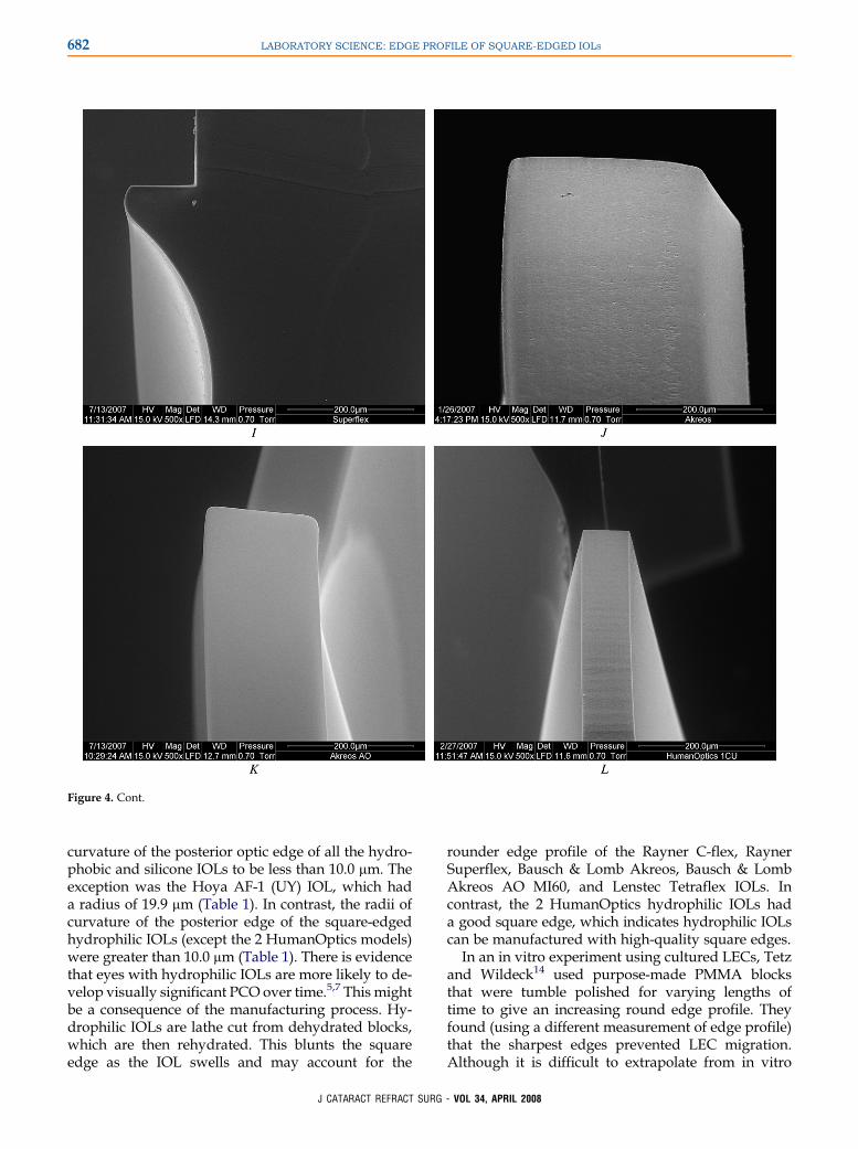
Figure 4. Scans of 17 different commercially available square-edged IOLs.A: Alcon AcrySof SA60WF. B: Alcon AcrySof SN60AT.C: Alcon Acry-SofMA60AC.D: AMOSensar AR40e.E: HoyaAF-1 (UY). F: Thinnest edge of Rayner C-flex.G: Thickest edge of Rayner C-flex at the optic–hapticjunction.H: Thinnest edge of Rayner the Superflex. I: Thickest edge of the Rayner Superflex at optic–haptic junction. J: Bausch& LombAkreos.K:Bausch & Lomb Akreos AO MI60. L: HumanOptics 1CU. M: HumanOptics Microlens MC611 MI-B. N: Lenstec Tetraflex. O: Bausch & LombSoflex SE. P: Bausch & Lomb SofPort AO. Q: AMO Clariflex CLRFLXC. R: AMO Tecnis Z9000. S: AMO Tecnis ZM9000.
This studywas prompted by the results in our recentclinical investigation of PCO. Our prospective ran-domized trial of fellow eyes with an Alcon AcrySofSN60AT IOL in 1 eye and a Hoya AF-1 (UY) IOL inthe fellow eye showed more PCO with the latter IOL(unpublished data). Although both IOLs are hydro-phobic with similar geometry and are marketed ashaving a square-edged profile, the Hoya IOL hadpoorer PCO performance. It appears to have beenslightly tumble polished, which smoothed the edge
J CATARACT REFRACT SUR
and thereby caused the IOL to lose its PCO-preventionproperties.
Scanning electron microscopy has a long track re-cord in IOL evaluation.16–24 Goldberg et al.25 advocatelow-voltage SEM using minimal or no conducting sur-face coating to analyze IOL surfaces. However, untilrecently, the validity of SEM results has suffered be-cause water-containing materials must be dehydratedfor scanning, which deforms the specimen. Aftera long exercise, we were able to standardize
G - VOL 34, APRIL 2008

681LABORATORY SCIENCE: EDGE PROFILE OF SQUARE-EDGED IOLS
Figure 4. Cont.
a technique in which the IOLs could be scanned ata pressure of 0.7 torr with no conductive coating; fur-ther lowering the pressure below 0.1 torr or loweringthe voltage below 15 KV resulted in greater loss of res-olution. Our scanning and measurement techniquewas standardized to obtain the best resolution in a re-peatable manner. The parameters used did not affectthe properties of the IOLs. No difference in scanningtechnique was necessary for hydrophilic IOLs withthe ESEM used in this study. However, thorough rins-ing of hydrophilic IOLswith distilledwater is requiredbefore scanning to avoid salt crystallization on theIOL. The IOLs can be scanned using these settings by
J CATARACT REFRACT SUR
ESEM without dehydration; therefore, there is no de-formation of shape, which is important to the properevaluation of edge profile.
In this study, using ESEM, we examined the edgeprofile of 17 IOLs, all marketed as having a squareedge. All IOLs examined had a power of 20.0 D. Whilestandardizing the measurement technique for the pos-terior optic edge profile, we found that displacementssmaller than 40 pixels around the midpoint causednoise and larger than 40 pixels resulted in exaggerateddifferences between the radii of curvature of differentIOLs. Hence, we standardized the displacement of 40pixels around the midpoint. We found the radii of
G - VOL 34, APRIL 2008
682 LABORATORY SCIENCE: EDGE PROFILE OF SQUARE-EDGED IOLS
Figure 4. Cont.
curvature of the posterior optic edge of all the hydro-phobic and silicone IOLs to be less than 10.0 mm. Theexception was the Hoya AF-1 (UY) IOL, which hada radius of 19.9 mm (Table 1). In contrast, the radii ofcurvature of the posterior edge of the square-edgedhydrophilic IOLs (except the 2 HumanOptics models)were greater than 10.0 mm (Table 1). There is evidencethat eyes with hydrophilic IOLs are more likely to de-velop visually significant PCO over time.5,7 This mightbe a consequence of the manufacturing process. Hy-drophilic IOLs are lathe cut from dehydrated blocks,which are then rehydrated. This blunts the squareedge as the IOL swells and may account for the
J CATARACT REFRACT SU
rounder edge profile of the Rayner C-flex, RaynerSuperflex, Bausch & Lomb Akreos, Bausch & LombAkreos AO MI60, and Lenstec Tetraflex IOLs. Incontrast, the 2 HumanOptics hydrophilic IOLs hada good square edge, which indicates hydrophilic IOLscan be manufactured with high-quality square edges.
In an in vitro experiment using cultured LECs, Tetzand Wildeck14 used purpose-made PMMA blocksthat were tumble polished for varying lengths oftime to give an increasing round edge profile. Theyfound (using a different measurement of edge profile)that the sharpest edges prevented LEC migration.Although it is difficult to extrapolate from in vitro
RG - VOL 34, APRIL 2008

683LABORATORY SCIENCE: EDGE PROFILE OF SQUARE-EDGED IOLS
Figure 4. Cont.
to clinical work, our results appear to be comparableto theirs, indicating that an edge must be as sharp aspossible to be effective in preventing PCO. Intraocu-lar lenses with a radius of curvature of less than10.0 mm appear to have good PCO performance.The Hoya AF-1 (UY) IOL, with a radius of 19.9 mm,has comparatively poor PCO performance. This indi-cates that the minimum edge profile (radius of curva-ture) of the posterior optic edge should be in theregion of 10.0 mm, and we predict that IOLs with agreater radius of curvature will have a comparativelypoorer PCO performance.
J CATARACT REFRACT SU
The reason square-edged IOLs reduce PCO re-mains controversial. Nishi and Nishi10 infer that anIOL with square-edged optic geometry producesa sharp bend in the posterior capsule in vivo andthis sharp bend prevents LEC migration secondaryto contact inhibition. However, Nagamoto and Egu-chi13 and Bhermi et al.15 suggest that under in vitroconditions, LEC migration is not affected by a changein the shape of the substrate. Boyce et al.26 proposea mathematical model of the pressure profile that ex-ists between an IOL optic and the posterior capsule,suggesting that an IOL with a square edge exerts
RG - VOL 34, APRIL 2008

684 LABORATORY SCIENCE: EDGE PROFILE OF SQUARE-EDGED IOLS
Figure 4. Cont.
more pressure on the posterior lens capsule at theedge of the optic than an IOL with a round edgeand this forms a mechanical barrier to LEC migra-tion (Boyce J, et al. IOVS 2000; 41:ARVO Abstract2579).
Posterior vaulting of the optic by forward flexion ofthe haptics, capsule fibrosis, and increased adhesiveforces between the lens capsule and acrylic IOLswould act synergistically to increase this force (BoyceJF, et al. IOVS 2000; 41:ARVO Abstract 2579). Table 1shows there was a wide variation in the edge thicknessof the IOLs, and it is possible that edge thickness alsohas a role in PCO prevention as it is conceivable that
J CATARACT REFRACT SUR
a thicker IOL occupies more space in the bag, whichwould increase the effect of capsular bag fibrosis push-ing the optic edge against the posterior capsule. Thismay give a comparative advantage to thicker IOLsand a disadvantage to some of the newer thinnerIOLs designed for smaller incision surgery. The roleof optic edge thickness in prevention of PCO remainsto be explored and to what extent small differencesin edge profiles have a clinical relevance remains tobe explored by clinical PCO studies Our results sug-gest that the difference in the posterior optic edgeprofile may explain why some IOLs marketedas square-edged IOLs have relatively poor PCO
G - VOL 34, APRIL 2008

685LABORATORY SCIENCE: EDGE PROFILE OF SQUARE-EDGED IOLS
Table 1. Radii of curvature of the posterior square edges and theedge thicknesses.
Intraocular Lens
Radius ofCurvature
(mm)
EdgeThickness
(mm)
Hydrophobic acrylicAlcon AcrySof SN60WF 8.5 197.7Alcon AcrySof SN60AT 8.4 198.7Alcon AcrySof MA60AC 9.9 306.8AMO Sensar AR40e 8.3 361.1Hoya AF-1 (UY) 19.9 259.9
Hydrophilic acrylicRayner C-flex (thinnest ridge) 18.2 405.9Rayner C-flex (thickest ridge) 19.6 *Rayner Superflex(thinnest ridge)
15.6 379.3
Rayner Superflex(thickest ridge)
10.6 *
Bausch & Lomb Akreos 15.9 375.1Bausch & LombAkreos AO MI60
14.3 181.3
HumanOptics 1CU 8.6 73.8HumanOptics Microlens MC611 MI-B
9.1 189.3
Lenstec Tetraflex 23.1 209.8Silicone
Bausch & LombSoflex SE
8.3 309.5
Bausch & LombSofPort AO
7.6 293.4
AMO Clariflex CLRFLXC 8.3 271.5AMO Tecnis Z9000 9.2 447.0AMO Tecnis ZM9000 9.0 436.2
*This IOL was too thick at the optic–haptic junction to be measured at thismagnification.
Figure 5.Radii of curvatureofposterioroptic edge in thehydrophobicacrylic, hydrophilic acrylic, and silicone IOL groups.
J CATARACT REFRACT SUR
performance and may explain why some IOL mate-rials appear to have better PCO performance thanothers.
REFERENCES1. Apple DJ, Peng Q, Visessook N, et al. Surgical prevention of
posterior capsule opacification. Part 1: progress in eliminating
this complication of cataract surgery. J Cataract Refract Surg
2000; 26:180–187
2. Davidson MG, Morgan DK, McGahan MC. Effect of surgical
technique on in vitro posterior capsule opacification. J Cataract
Refract Surg 2000; 26:1550–1554
3. Ram J, Pandey SK, Apple DJ, et al. Effect of in-the-bag intraoc-
ular lens fixation on the prevention of posterior capsule opacifi-
cation. J Cataract Refract Surg 2001; 27:1039–1046
4. Hollick EJ, Spalton DJ, Ursell PG, et al. The effect of polymethyl-
methacrylate, silicone, and polyacrylic intraocular lenses on pos-
terior capsular opacification 3 years after cataract surgery.
Ophthalmology 1999; 106:49–54; discussion by RC Drews,
54–55
5. Heatley CJ, Spalton DJ, Kumar A, et al. Comparison of posterior
capsule opacification rates between hydrophilic and hydropho-
bic single-piece acrylic intraocular lenses. J Cataract Refract
Surg 2005; 31:718–724
6. Ursell PG, Spalton DJ, Pande MV, et al. Relationship between
intraocular lens biomaterials and posterior capsular Opacifica-
tion. J Cataract Refract Surg 1998; 24:352–360
7. Georgopoulos M, Findl O, Menapace R, et al. Influence of intra-
ocular lens material on regeneratory posterior capsule opacifica-
tion after neodymium:YAG laser capsulotomy. J Cataract
Refract Surg 2003; 29:1560–1565
8. Wejde G, Kugelberg M, Zetterstrom C. Posterior capsule opaci-
fication: comparison of 3 intraocular lenses of different materials
and design. J Cataract Refract Surg 2003; 29:1556–1559
9. Nishi O, Nishi K, Wickstrom K. Preventing lens epithelial cell
migration using intraocular lenses with sharp rectangular edges.
J Cataract Refract Surg 2000; 26:1543–1549
10. Nishi O, Nishi K. Preventing posterior capsule opacification by
creating a discontinuous sharp bend in the capsule. J Cataract
Refract Surg 1999; 25:521–526
Figure 6. Thickness at the edge of the IOL optic in the hydrophobicacrylic, hydrophilic acrylic, and silicone IOL groups. The thicknessof the thickest ridge at the optic–haptic junction of the RaynerIOLswere immeasurable as theyweremore than 500 mm; thus, theseIOLs were not included in the analysis.
G - VOL 34, APRIL 2008

686 LABORATORY SCIENCE: EDGE PROFILE OF SQUARE-EDGED IOLS
11. Peng Q, Visessook N, Apple DJ, et al. Surgical prevention of
posterior capsule opacification. Part 3: intraocular lens optic bar-
rier effect as a second line of defense. J Cataract Refract Surg
2000; 26:198–213
12. Hayashi K, Hayashi H. Posterior capsule opacification in the
presence of an intraocular lens with a sharp versus rounded
optic edge. Ophthalmology 2005; 112:1550–1556
13. Nagamoto T, Eguchi G. Effect of intraocular lens design on
migration of lens epithelial cells onto the posterior capsule.
J Cataract Refract Surg 1997; 23:866–872
14. Tetz M, Wildeck A. Evaluating and defining the sharpness of
intraocular lenses: part 1: influence of optic design on the growth
of the lens epithelial cells in vitro. J Cataract Refract Surg 2005;
31:2172–2179
15. Bhermi GS, Spalton DJ, El-Osta AAR, Marshall J. Failure of
a discontinuous bend to prevent lens epithelial cell migration in
vitro. J Cataract Refract Surg 2002; 28:1256–1261
16. Drews RC, Smith ME, Okun N. Scanning electron microscopy of
intraocular lenses. Ophthalmology 1978; 85:415–424
17. Apple DJ, Mamalis N, Loftfield K, et al. Complications of intraoc-
ular lenses. A historical and histopathological review. Surv Oph-
thalmol 1984; 29:1–54
18. Koch DD, Samuelson SW, Dimonie V. Surface analysis of sur-
face-passivated intraocular lens. J Cataract Refract Surg
1991; 17:131–138
19. Kohnen T, Dick B, Jacobi KW. Surface alterations on PMMA-in-
traocular lenses induced by different implantation forceps. Eur J
Implant Refract Surg 1994; 6:138–142
20. Stacholy J, Yalon M, Goldberg EP. Improved procedure for sur-
face analysis of explanted intraocular lenses by combined light
J CATARACT REFRACT SUR
microscopy and scanning electron microscopy. J Cataract
Refract Surg 1989; 15:215–217
21. Tsai JC, Castaneda VE, Apple DJ, et al. Scanning electron
microscopic study of modern silicone intraocular lenses. J Cata-
ract Refract Surg 1992; 18:232–235
22. Omar O, Mamalis N, Veiga J, et al. Scanning electron micro-
scopic characteristics of small-incision intraocular lenses. Oph-
thalmology 1996; 103:1124–1129
23. Kohnen T, Magdowski G, Koch DD. Scanning electron micro-
scopic analysis of foldable acrylic and hydrogel intraocular
lenses. J Cataract Refract Surg 1996; 22:1342–1350
24. Mencucci R, Ponchietti C, Nocentini L, et al. Scanning electron
microscopic analysis of acrylic intraocular lenses for microinci-
sion cataract surgery. J Cataract Refract Surg 2006; 32:318–
323
25. Goldberg EP, Yalon M, Longo WE. Low voltage SEM for unique
surface analysis of prosthetic devices. Mater Res Soc Symp
Proc 1989; 110:355–360
26. Boyce JF, Bhermi GS, Spalton DJ, El-Osta AR. Mathematical
modeling of the forces between an intraocular lens and the cap-
sule. J Cataract Refract Surg 2002; 28:1853–1859
First author:Mayank A Nanavaty, DO
Department of Ophthalmology,St. Thomas’ Hospital, London,United Kingdom
G - VOL 34, APRIL 2008
Copyright © 2022 FDOKUMEN