
This manual should be considered a permanent part of the ...
111
This manual should be considered a permanent part of the vehicle and should remain with the vehicle when it is resold. This publication includes the latest production information available before printing. Honda Motor Co., Ltd. reserves the right to make changes at any time without notice and without incurring any obligation. No part of this publication may be reproduced without written permission. The vehicle pictured in this owner’s manual may not match your actual vehicle. For any query or assistance, please call Customer care number: 1800 103 3434 (Toll free) © 2020 Honda Motor Co., Ltd.
-
Upload
khangminh22 -
Category
Documents
-
view
4 -
download
0
Transcript of This manual should be considered a permanent part of the ...
This manual should be considered a permanent part of the vehicle and should remain with the vehicle when it is resold.
This publication includes the latest production information available before printing. Honda Motor Co., Ltd. reserves the right to make changes at any time without notice and without incurring any obligation.
No part of this publication may be reproduced without written permission.
The vehicle pictured in this owner’s manual may not match your actual vehicle.
For any query or assistance, please call Customer care number: 1800 103 3434 (Toll free)
© 2020 Honda Motor Co., Ltd.
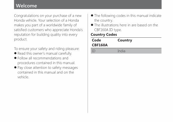
z The following codes in this manual indicate the country.
z The illustrations here in are based on the CBF160A ID type.
Country Codes Code CountryCBF160A ID India
Congratulations on your purchase of a new Honda vehicle. Your selection of a Honda makes you part of a worldwide family of satisfied customers who appreciate Honda’s reputation for building quality into every product.
To ensure your safety and riding pleasure: z Read this owner’s manual carefully. z Follow all recommendations and procedures contained in this manual.
z Pay close attention to safety messages contained in this manual and on the vehicle.
Welcome
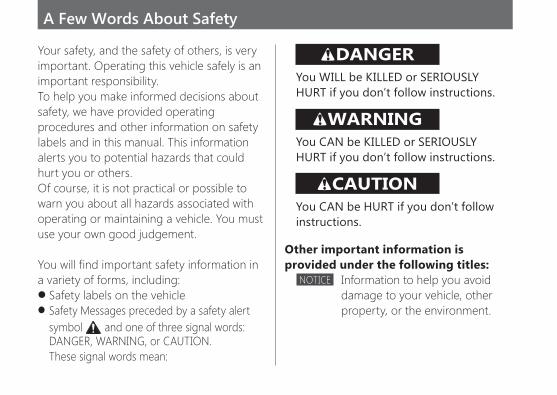
Your safety, and the safety of others, is very important. Operating this vehicle safely is an important responsibility. To help you make informed decisions about safety, we have provided operating procedures and other information on safety labels and in this manual. This information alerts you to potential hazards that could hurt you or others. Of course, it is not practical or possible to warn you about all hazards associated with operating or maintaining a vehicle. You must use your own good judgement.
You will find important safety information in a variety of forms, including:
z Safety labels on the vehicle z Safety Messages preceded by a safety alert symbol and one of three signal words: DANGER, WARNING, or CAUTION. These signal words mean:
DANGERYou WILL be KILLED or SERIOUSLY HURT if you don’t follow instructions.
WARNINGYou CAN be KILLED or SERIOUSLY HURT if you don’t follow instructions.
CAUTIONYou CAN be HURT if you don’t follow instructions.
Other important information is provided under the following titles:
NOTICE Information to help you avoid damage to your vehicle, other property, or the environment.
A Few Words About Safety
Contents
Vehicle Safety P. 2
Operation Guide P. 14
Maintenance P. 27
Troubleshooting P. 69
Information P. 83
Specifications P. 95
Warranty Policy P. 98
Index P. 106
Safety Guidelines ............................................................P. 3Image Labels .......................................................................P. 6Safety Precautions .........................................................P. 8Riding Precautions ........................................................P. 9Accessories & Modifications ..............................P. 12Loading .................................................................................P. 13
Vehicle Safety
This section contains important information for safe riding of your vehicle. Please read this section carefully.

3
Vehicle SafetySafety Guidelines
Safety GuidelinesFollow these guidelines to enhance your safety:
z Perform all routine and regular inspections specified in this manual.
z Stop the engine and keep sparks and flame away before filling the fuel tank.
z Do not run the engine in enclosed or partly enclosed areas. Carbon monoxide in exhaust gases is toxic and can kill you.
Always Wear a HelmetIt’s a proven fact: helmets and protective apparel significantly reduce the number and severity of head and other injuries. So always wear an approved helmet and protective apparel. P. 8
Before RidingMake sure that you are physically fit, mentally focused and free of alcohol and drugs. Check
that you and your passenger are both wearing an approved helmet and protective apparel. Instruct your passenger on holding onto the grab rail or your waist, leaning with you in turns, and keeping their feet on the footpegs, even when the vehicle is stopped.
Take Time to Learn & PracticeEven if you have ridden other vehicles, practice riding in a safe area to become familiar with how this vehicle works and handles, and to become accustomed to the vehicle’s size and weight.
Ride DefensivelyAlways pay attention to other vehicles around you, and do not assume that other drivers see you. Be prepared to stop quickly or perform an evasive maneuver.
continued

4
Vehicle Safety
Safety Guidelines
Make Yourself Easy to SeeMake yourself more visible, especially at night, by wearing bright reflective clothing, positioning yourself so other drivers can see you, signaling before turning or changing lanes, and using your horn when necessary.
Ride within Your LimitsNever ride beyond your personal abilities or faster than conditions warrant. Fatigue and inattention can impair your ability to use good judgement and ride safely.
Don’t Drink and RideAlcohol and riding don’t mix. Even one alcoholic drink can reduce your ability to respond to changing conditions, and your reaction time gets worse with every additional drink. Don’t drink and ride, and don’t let your friends drink and ride either.
Keep Your Honda in Safe ConditionIt’s important to keep your vehicle properly maintained and in safe riding condition. Inspect your vehicle before every ride and perform all recommended maintenance. Never exceed load limits ( P. 13), and do not modify your vehicle or install accessories that would make your vehicle unsafe ( P. 12).
If You are Involved in a CrashPersonal safety is your first priority. If you or anyone else has been injured, take time to assess the severity of the injuries and whether it is safe to continue riding. Call for emergency assistance if needed. Also follow applicable laws and regulations if another person or vehicle is involved in the crash.
If you decide to continue riding, first turn the ignition switch to the OFF position, and evaluate the condition of your vehicle. Inspect for fluid

5
Vehicle SafetySafety Guidelines
leaks, check the tightness of critical nuts and bolts, and check the handlebar, control levers, brakes, and wheels. Ride slowly and cautiously.Your vehicle may have suffered damage that is not immediately apparent. Have your vehicle thoroughly checked at a qualified service facility as soon as possible.
Carbon Monoxide HazardExhaust contains poisonous carbon monoxide, a colourless, odorless gas. Breathing carbon monoxide can cause loss of consciousness and may lead to death.
If you run the engine in confined or even partly enclosed area, the air you breathe could contain a dangerous amount of carbon monoxide. Never run your vehicle inside a garage or other enclosure.
WARNINGRunning the engine of your vehicle while in an enclosed or even partially enclosed area can cause a rapid build-up of toxic carbon monoxide gas.
Breathing this colourless, odorless gas can quickly cause unconsciousness and lead to death.
Only run your vehicle’s engine when it is located in a well ventilated area outdoors.

6
Vehicle Safety
Image Labels
Image LabelsThe following pages describe the label meanings. Some labels warn you of potential hazards that could cause serious injury. Others provide important safety information. Read this information carefully and don’t remove the labels.
If a label comes off or becomes hard to read, contact your dealer for a replacement.
There is a specific symbol on each label. The meanings of each symbol and label areas follows.
Read instructions contained in Owner’s Manual carefully.
Read instructions contained in Shop Manual carefully. In the interest of safety, take the vehicle to be serviced only by your dealer.
DANGER (with RED background)You WILL be KILLED or SERIOUSLY HURT if you don’t follow instructions.WARNING (with ORANGE background)You CAN be KILLED or SERIOUSLY HURT if you don’t follow instructions.CAUTION (with YELLOW background)You CAN be HURT if you don’t followinstructions.
7
Vehicle SafetyImage Labels
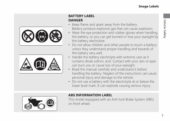
BATTERY LABELDANGER• Keep flame and spark away from the battery.
Battery produce explosive gas that can cause explosion.• Wear the eye protection and rubber gloves when handling
the battery, or you can get burned or lose your eyesight by the battery electrolyte.
• Do not allow children and other people to touch a battery unless they understand proper handling and hazards of the battery very well.
• Handle the battery electrolyte with extreme care as it contains dilute sulfuric acid. Contact with your skin or eyes can burn you or cause loss of your eyesight.
• Read this manual carefully and understand it before handling the battery. Neglect of the instructions can cause personal injury and damage to the vehicle.
• Do not use a battery with the electrolyte at or below the lower level mark. It can explode causing serious injury.
ABS INFORMATION LABELThis model equipped with an Anti-lock Brake System (ABS) on front wheel.
8
Vehicle Safety
Safety Precautions
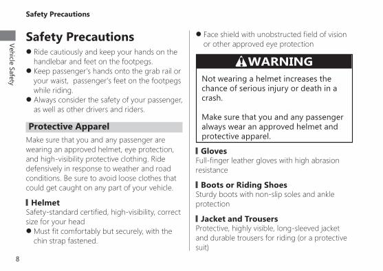
Safety Precautions z Ride cautiously and keep your hands on the handlebar and feet on the footpegs.
z Keep passenger’s hands onto the grab rail or your waist, passenger’s feet on the footpegs while riding.
z Always consider the safety of your passenger, as well as other drivers and riders.
Protective ApparelMake sure that you and any passenger are wearing an approved helmet, eye protection, and high-visibility protective clothing. Ride defensively in response to weather and road conditions. Be sure to avoid loose clothes that could get caught on any part of your vehicle.
▌HelmetSafety-standard certified, high-visibility, correct size for your head
z Must fit comfortably but securely, with the chin strap fastened.
z Face shield with unobstructed field of vision or other approved eye protection
WARNINGNot wearing a helmet increases the chance of serious injury or death in a crash.
Make sure that you and any passenger always wear an approved helmet and protective apparel.
▌GlovesFull-finger leather gloves with high abrasion resistance
▌Boots or Riding ShoesSturdy boots with non-slip soles and ankle protection
▌ Jacket and TrousersProtective, highly visible, long-sleeved jacket and durable trousers for riding (or a protective suit)
9
Vehicle SafetyRiding Precautions
Riding PrecautionsRunning-in Period
During the first 500 km (300 miles) of running, follow these guidelines to ensure your vehicle’s future reliability and performance.
z Avoid full-throttle starts and rapid acceleration.
z Avoid hard braking and rapid down-shifts. z Ride conservatively.
BrakesObserve the following guidelines:
z Avoid excessively hard braking and down-shifting.
► Sudden braking can reduce the vehicle’s stability. ►Where possible, reduce speed before turning; otherwise you risk sliding out.
z Exercise caution on low traction surfaces. ► The tyres slip more easily on such surfaces, and braking distances are longer.
z Avoid continuous braking. ► Repeated braking, such as when descending long, steep slopes can seriously overheat the brakes, reducing their effectiveness. Use engine braking with intermittent use of the brakes to reduce speed.
z For full braking effectiveness, operate both the front and rear brakes together.
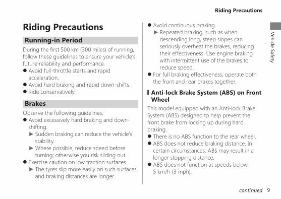
▌Anti-lock Brake System (ABS) on Front Wheel
This model equipped with an Anti-lock Brake System (ABS) designed to help prevent the front brake from locking up during hard braking.
z There is no ABS function to the rear wheel. z ABS does not reduce braking distance. In certain circumstances, ABS may result in a longer stopping distance.
z ABS does not function at speeds below 5 km/h (3 mph).
continued

10
Vehicle Safety
Riding Precautions
Parking z Park on a firm, level surface. z If you must park on a slight incline or loose surface, park so that the vehicle cannot move or fall over.
z Make sure that high-temperature parts cannot come into contact with flammable materials.
z Do not touch the engine, muffler, brakes and other high-temperature parts until they cool down.
z To reduce the likelihood of theft, always lock the handlebar and remove the key when leaving the vehicle unattended. Use of an anti-theft device is also recommended.
▌Parking with the Side Stand or Centre Stand1. Stop the engine. 2. Using the side stand
Push the side stand down. Slowly lean the vehicle to the left until its
weight rests on the side stand.
z The brake lever may recoil slightly when applying the brakes. This is normal.
z Always use the recommended front/rear tyres and sprockets to ensure correct ABS operation.
▌Engine Braking
Engine braking helps slow your vehicle down when you release the throttle. For further slowing action, downshift to a lower gear. Use engine braking with intermittent use of the brakes to reduce speed when descending long, steep slopes.
▌Wet or Rainy Conditions
Road surfaces are slippery when wet, and wet brakes further reduce braking efficiency.Exercise extra caution when braking in wet conditions.If the brakes get wet, apply the brakes while riding at low speed to help them dry.
11
Vehicle SafetyRiding Precautions
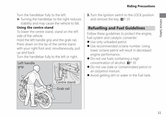
Turn the handlebar fully to the left. ► Turning the handlebar to the right reduces stability and may cause the vehicle to fall.
Using the centre stand To lower the centre stand, stand on the left side of the vehicle.
Hold the left handle grip and the grab rail. Press down on the tip of the centre stand with your right foot and, simultaneously, pull up and back.
Turn the handlebar fully to the left or right.
Left handle grip
Grab rail
Centre stand
3. Turn the ignition switch to the LOCK position and remove the key. P. 19
Refuelling and Fuel GuidelinesFollow these guidelines to protect the engine, fuel system and catalytic converter:
z Use only unleaded petrol. z Use recommended octane number. Using lower octane petrol will result in decreased engine performance.
z Do not use fuels containing a high concentration of alcohol. P. 93
z Do not use stale or contaminated petrol or an oil/petrol mixture.
z Avoid getting dirt or water in the fuel tank.
12
Vehicle Safety
Accessories & Modifications
Accessories & ModificationsWe strongly advise that you do not add any accessories that were not specifically designed for your vehicle by Honda or make modifications to your vehicle from its original design. Doing so can make it unsafe. Modifying your vehicle may also void your warranty and make your vehicle illegal to operate on public roads. Before deciding to install accessories on your vehicle be certain the modification is safe and legal.
WARNINGImproper accessories or modifications can cause a crash in which you can be seriously hurt or killed.
Follow all instructions in this owner’s manual regarding accessories and modifications.
Do not pull a trailer with, or attach a sidecar to, your vehicle. Your vehicle was not designed for these attachments, and their use can seriously impair your vehicle’s handling.

13
Vehicle SafetyLoading
Loading z Carrying extra weight affects your vehicle’s handling, braking and stability. Always ride at a safe speed for the load you are carrying.
z Avoid carrying an excessive load and keep within specified load limits.Maximum weight capacity P. 95
z Tie all luggage securely, evenly balanced and close to the centre of the vehicle.
z Do not place objects near the lights or the muffler.
WARNINGOverloading or improper loading can cause a crash and you can be seriously hurt or killed.
Follow all load limits and other loading guidelines in this manual.

14
Operation G
uide
Parts Location
Document bag P. 25
First aid kit P. 25
Engine oil fill cap/ dipstick P. 50
Right side cover P. 47
Front brake leverThrottle grip P. 65
Fuel fill cap P. 24
Seat P. 46
Crankcase breather P. 66
Tool kit P. 25
Spark plug P. 48
Rear brake pedal P. 55
Kick starter

15
Operation G
uide
Engine oil drain bolt P. 52
Battery P. 43
Centre stand P. 11
Side stand P. 59
Seat lock P. 46
Left side cover P. 47
Shift lever P. 23
Fuse box P. 80
Clutch lever P. 63
Data link connector
16
Operation G
uide
Instruments
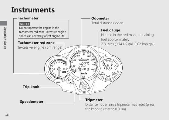
Speedometer TripmeterDistance ridden since tripmeter was reset (press trip knob to reset to 0.0 km).
Tachometer
Trip knob
Fuel gaugeNeedle in the red mark, remaining fuel approximately2.8 litres (0.74 US gal, 0.62 Imp gal)
NOTICE Do not operate the engine in the tachometer red zone. Excessive engine speed can adversely affect engine life.
Tachometer red zone(excessive engine rpm range)
OdometerTotal distance ridden.
17
Operation G
uide
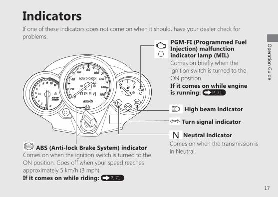
IndicatorsIf one of these indicators does not come on when it should, have your dealer check for problems.
PGM-FI (Programmed Fuel Injection) malfunction indicator lamp (MIL)
Comes on briefly when the ignition switch is turned to the ON position.
If it comes on while engine is running: P. 71
Neutral indicator NComes on when the transmission is in Neutral.
Turn signal indicator
High beam indicator
ABS (Anti-lock Brake System) indicatorComes on when the ignition switch is turned to theON position. Goes off when your speed reaches approximately 5 km/h (3 mph).If it comes on while riding: P. 71
18
Operation G
uide
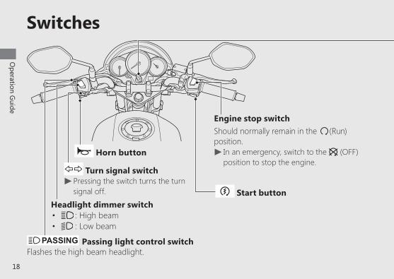
Switches
Headlight dimmer switch• : High beam• : Low beam
Horn button
Turn signal switch u Pressing the switch turns the turn signal off.
Engine stop switchShould normally remain in the 8(Run) position.
u In an emergency, switch to the 9 (OFF) position to stop the engine.
Passing light control switchFlashes the high beam headlight.
Start button
19
Operation G
uide
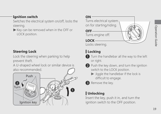
Ignition switchSwitches the electrical system on/off, locks the steering.
u Key can be removed when in the OFF or LOCK position.
ONTurns electrical system on for starting/riding.
OFFTurns engine off.
LOCKLocks steering.
Steering LockLock the steering when parking to help prevent theft.A U-shaped wheel lock or similar device is also recommended.
# Lockinga Turn the handlebar all the way to the left
or right.b Push the key down, and turn the ignition
switch to the LOCK position. u Jiggle the handlebar if the lock is difficult to engage.
c Remove the key.
# UnlockingInsert the key, push it in, and turn the ignition switch to the OFF position.
a
b
Push
Turn
Ignition key
20
Operation G
uide
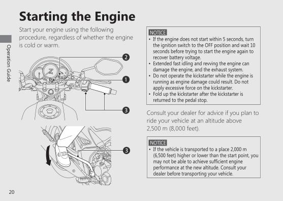
Starting the Engine NOTICE • If the engine does not start within 5 seconds, turn
the ignition switch to the OFF position and wait 10 seconds before trying to start the engine again to recover battery voltage.
• Extended fast idling and revving the engine can damage the engine, and the exhaust system.
• Do not operate the kickstarter while the engine is running as engine damage could result. Do not apply excessive force on the kickstarter.
• Fold up the kickstarter after the kickstarter is returned to the pedal stop.
Start your engine using the following procedure, regardless of whether the engine is cold or warm.
Consult your dealer for advice if you plan to ride your vehicle at an altitude above 2,500 m (8,000 feet).
b
NOTICE • If the vehicle is transported to a place 2,000 m
(6,500 feet) higher or lower than the start point, you may not be able to achieve sufficient engine performance at the new altitude. Consult your dealer before transporting your vehicle.
c
c
a
21
Operation G
uide
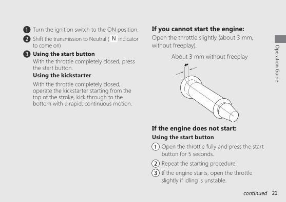
a Turn the ignition switch to the ON position.b Shift the transmission to Neutral ( indicator
to come on)c Using the start button
With the throttle completely closed, press the start button.
Using the kickstarterWith the throttle completely closed, operate the kickstarter starting from the top of the stroke, kick through to the bottom with a rapid, continuous motion.
If you cannot start the engine:Open the throttle slightly (about 3 mm,without freeplay).
continued
About 3 mm without freeplay
If the engine does not start:Using the start button
aa Open the throttle fully and press the start button for 5 seconds.
bb Repeat the starting procedure.
cc If the engine starts, open the throttle slightly if idling is unstable.
22
Operation G
uide
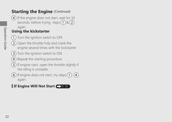
Starting the Engine (Continued)
dd If the engine does not start, wait for 10 seconds, before trying steps aa & bb again.
Using the kickstarteraa Turn the ignition switch to OFF.
bb Open the throttle fully and crank the engine several times with the kickstarter.
cc Turn the ignition switch to ON.
dd Repeat the starting procedure.
ee If engine start, open the throttle slightly if the idling is unstable.
ff If engine does not start, try steps aa- dd again.
# If Engine Will Not Start P. 70
23
Operation G
uide
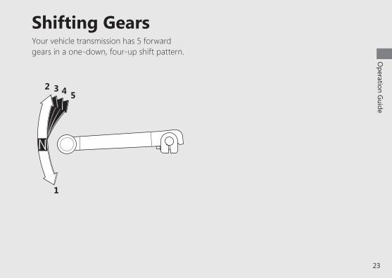
Shifting GearsYour vehicle transmission has 5 forward gears in a one-down, four-up shift pattern.
1
2 3 4 5
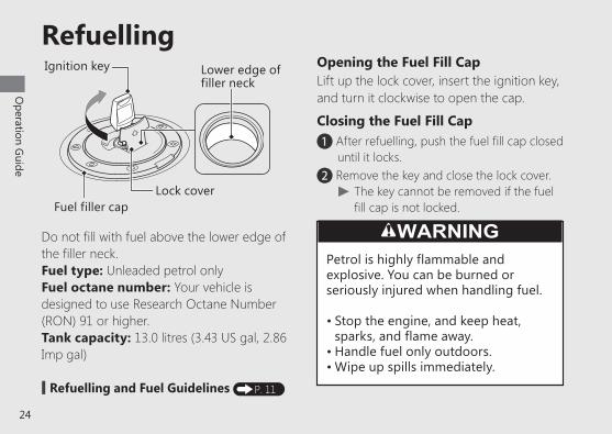
Do not fill with fuel above the lower edge of the filler neck.Fuel type: Unleaded petrol only Fuel octane number: Your vehicle is designed to use Research Octane Number (RON) 91 or higher. Tank capacity: 13.0 litres (3.43 US gal, 2.86 Imp gal)
Opening the Fuel Fill CapLift up the lock cover, insert the ignition key,and turn it clockwise to open the cap.
Closing the Fuel Fill CapaAfter refuelling, push the fuel fill cap closed
until it locks.bRemove the key and close the lock cover.
u The key cannot be removed if the fuel fill cap is not locked.
# Refuelling and Fuel Guidelines P. 11
24
Operation G
uide
Refuelling
WARNINGPetrol is highly flammable and explosive. You can be burned or seriously injured when handling fuel.
• Stop the engine, and keep heat, sparks, and flame away.
• Handle fuel only outdoors.• Wipe up spills immediately.
Lock cover
Ignition key Lower edge of filler neck
Fuel filler cap
25
Operation G
uide
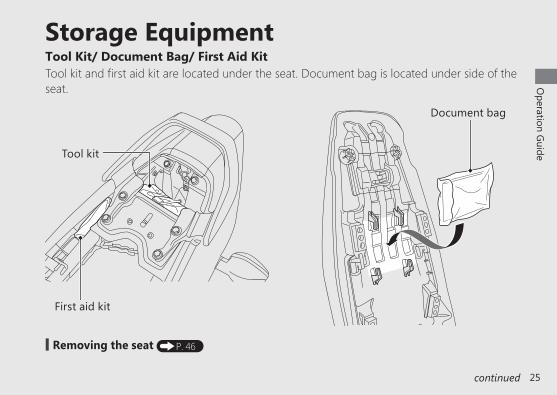
Storage EquipmentTool Kit/ Document Bag/ First Aid KitTool kit and first aid kit are located under the seat. Document bag is located under side of the seat.
Document bag
# Removing the seat P. 46
Tool kit
First aid kit
continued
26
Operation G
uide
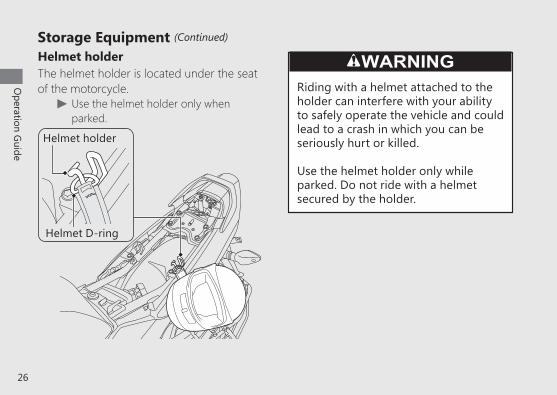
Helmet holderThe helmet holder is located under the seat of the motorcycle.
u Use the helmet holder only when parked.
WARNINGRiding with a helmet attached to theholder can interfere with your ability to safely operate the vehicle and could lead to a crash in which you can be seriously hurt or killed.
Use the helmet holder only while parked. Do not ride with a helmet secured by the holder.
Helmet D-ring
Helmet holder
Storage Equipment (Continued)

Importance of Maintenance ................................ P.28Maintenance Schedule ............................................. P.29Maintenance Fundamentals .................................P.32Tool .............................................................................................P.42Removing & Installing Body Components .....P.43
Battery .....................................................................................................P.43Drive Chain Case ........................................................................P.44Headlight Case ..............................................................................P.45Seat ..............................................................................................................P.46Side Cover ...........................................................................................P.47
Spark Plug ........................................................................... P.48Engine Oil ..............................................................................P.50
Brakes .......................................................................................P.53Side Stand .............................................................................P.59Drive Chain ......................................................................... P.60Clutch .......................................................................................P.63Throttle ...................................................................................P.65Crankcase Breather ..................................................... P.66Other Adjustments .......................................................P.67
Adjusting the Headlight Aim .......................................P.67Adjusting the Rear Suspension................................ P.68
Maintenance
Please read “Importance of Maintenance” and “Maintenance Fundamentals” carefully before attempting any maintenance. Refer to “Specifications” for service data.
28
Maintenance
Importance of MaintenanceKeeping your vehicle well-maintained is absolutely essential to your safety and to protect your investment, obtain maximum performance, avoid breakdowns, and reduce air pollution. Maintenance is the owner’s responsibility. Be sure to inspect your vehicle before each ride, and perform the periodic checks specified in the Maintenance Schedule. 2 P. 29
WARNINGImproperly maintaining your vehicle or failing to correct a problem before you ride can cause a crash in which you can be seriously hurt or killed.
Always follow the inspection and maintenance recommendations and schedules in this owner’s manual.
Maintenance SafetyAlways read the maintenance instructions before you begin each task, and make sure that you have the tools, parts, and skills required. We cannot warn you of every conceivable hazard that can arise in performing maintenance. Only you can decide whether or not you should perform a given task.
Follow these guidelines when performing maintenance.
z Stop the engine and remove the key. z Place your vehicle on a firm, level surface using the side stand, centre stand or a maintenance stand to provide support.
z Allow the engine, muffler, brakes, and other high-temperature parts to cool before servicing as you can get burned.
z Run the engine only when instructed, and do so in a well-ventilated area.
Importance of Maintenance

29
Maintenance
Maintenance Schedule
The maintenance schedule specifies the maintenance requirements necessary to ensure safe, dependable performance, and proper emission control.
Maintenance work should be performed in accordance with Honda’s standards and specifications by properly trained and equipped technicians. Your dealer meets all of these requirements. Keep an accurate record of maintenance to help ensure that your vehicle is properly maintained. Make sure that whomever performs the maintenance completes this record.
All scheduled maintenance is considered a normal owner operating cost and will be charged to you by your dealer. Retain all receipts. If you sell the vehicle, these receipts should be transferred with the vehicle to the new owner.
Honda recommends that your dealer should road test your vehicle after each periodic maintenance is carried out.

30
Maintenance
Maintenance Schedule
ItemsPre-ride Check
P.32
Frequency *1Annual Check
RegularReplace
Refer to
page
× 1,000 km 1 6 12 18 24 30 36× 1,000 mi 0.6 4 8 12 16 20 24Months 1 6 12 18 24 30 36
Fuel Line I I I I I I I –Fuel Level I –Throttle Operation I I I I I I I I 65Air Cleaner *2 R R 41Crankcase Breather*3 C C C C C C 66Spark Plug I R I R I R 48Valve Clearance I I I I I I –Engine Oil I R R R R R R R R 50Engine Oil Strainer Screen C C C –Engine Oil Centrifugal filter C C C –Engine Idle Speed I I I I I I I I –Evaporative Emission Control System I I –Drive Chain I 1000 km (600mi): I L 60
Maintenance Level : Intermediate. We recommend service by your
dealer, unless you have the necessary tools and are mechanically skilled.
Procedures are provided in an official Honda Shop Manual.
: Technical. In the interest of safety, have your vehicle serviced by your dealer.
Maintenance LegendI : Inspect (clean, adjust, lubricate, or replace, if
necessary)R : ReplaceC : CleanL : Lubricate
31
Maintenance
Maintenance Schedule
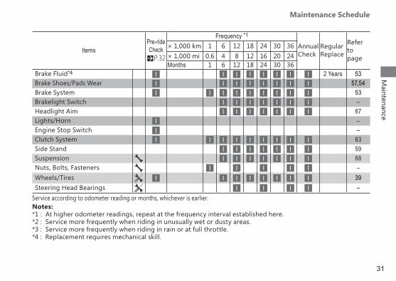
Notes:*1 : At higher odometer readings, repeat at the frequency interval established here.*2 : Service more frequently when riding in unusually wet or dusty areas.*3 : Service more frequently when riding in rain or at full throttle.*4 : Replacement requires mechanical skill.
ItemsPre-ride Check
P.32
Frequency *1
Annual Check
RegularReplace
Refer topage
× 1,000 km 1 6 12 18 24 30 36× 1,000 mi 0.6 4 8 12 16 20 24Months 1 6 12 18 24 30 36
Brake Fluid*4 I I I I I I I I 2 Years 53Brake Shoes/Pads Wear I I I I I I I I 57,54Brake System I I I I I I I I I 53Brakelight Switch I I I I I I I –Headlight Aim I I I I I I I 67Lights/Horn I –Engine Stop Switch I –Clutch System I I I I I I I I I 63Side Stand I I I I I I I 59Suspension I I I I I I I 68Nuts, Bolts, Fasteners I I I I I –Wheels/Tires I I I I I I I I 39Steering Head Bearings I I I I –
Service according to odometer reading or months, whichever is earlier.
32
Maintenance
Maintenance Fundamentals
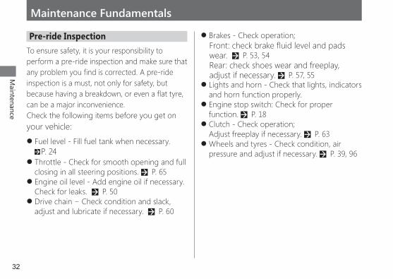
Pre-ride InspectionTo ensure safety, it is your responsibility to perform a pre-ride inspection and make sure that any problem you find is corrected. A pre-ride inspection is a must, not only for safety, but because having a breakdown, or even a flat tyre, can be a major inconvenience.Check the following items before you get on your vehicle:
z Fuel level - Fill fuel tank when necessary. 2 P. 24
z Throttle - Check for smooth opening and full closing in all steering positions. 2 P. 65
z Engine oil level - Add engine oil if necessary. Check for leaks. 2 P. 50
z Drive chain − Check condition and slack, adjust and lubricate if necessary. 2 P. 60
z Brakes - Check operation;Front: check brake fluid level and pads wear. 2 P. 53, 54Rear: check shoes wear and freeplay, adjust if necessary. 2 P. 57, 55
z Lights and horn - Check that lights, indicators and horn function properly.
z Engine stop switch: Check for proper function. 2 P. 18
z Clutch - Check operation; Adjust freeplay if necessary. 2 P. 63
z Wheels and tyres - Check condition, air pressure and adjust if necessary. 2 P. 39, 96
33
Maintenance
Maintenance Fundamentals
Replacing PartsAlways use Honda Genuine Parts or their equivalents to ensure reliability and safety.
WARNINGInstalling non-Honda parts may make your vehicle unsafe and cause a crash in which you can be seriously hurt or killed.
Always use Honda Genuine Parts or equivalents that have been designed and approved for your vehicle.
NOTICE Your battery is a maintenance-free type and can be permanently damaged if the cap strip is removed.
NOTICE An improperly disposed of battery can be harmful to the environment and human health.Always confirm local regulations for proper battery disposal instruction.
BatteryYour vehicle has a maintenance-free type battery. You do not have to check the battery electrolyte level or add distilled water. Clean the battery terminals if they become dirty or corroded.Do not remove the battery cap seals. There is no need to remove the cap when charging.
continued
34
Maintenance
# What to do in an emergencyIf any of the following occur, immediately see your doctor.
z Electrolyte splashes into your eyes: ►Wash your eyes repeatedly with cool water for at least 15 minutes. Using water under pressure can damage your eyes.
z Electrolyte splashes onto your skin: ► Remove affected clothing and wash your skin thoroughly using water.
z Electrolyte splashes into your mouth: ► Rinse mouth thoroughly with water, and do not swallow.
WARNINGThe battery gives off explosive hydrogen gas during normal operation. A spark or flame can cause the battery to explode with enough force to kill or seriously hurt you.
Wear protective clothing and a face shield, or have a skilled mechanic do the battery servicing.
# Cleaning the Battery Terminals1. Remove the battery. 2 P. 432. If the terminals are starting to corrode and
are coated with a white substance, wash with warm water and wipe clean.
Maintenance Fundamentals
35
Maintenance
Maintenance Fundamentals
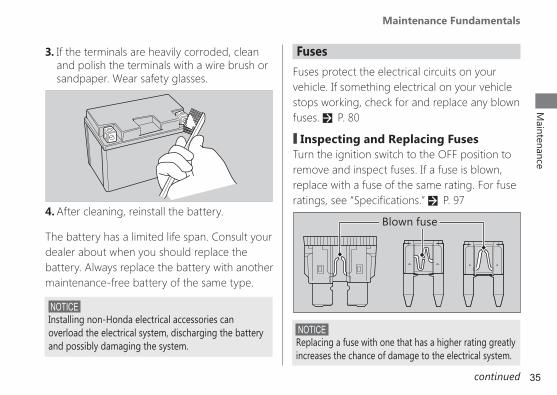
FusesFuses protect the electrical circuits on your vehicle. If something electrical on your vehicle stops working, check for and replace any blown fuses. 2 P. 80
# Inspecting and Replacing FusesTurn the ignition switch to the OFF position to remove and inspect fuses. If a fuse is blown, replace with a fuse of the same rating. For fuse ratings, see “Specifications.” 2 P. 97
Blown fuse
3. If the terminals are heavily corroded, clean and polish the terminals with a wire brush or sandpaper. Wear safety glasses.
4. After cleaning, reinstall the battery.
The battery has a limited life span. Consult your dealer about when you should replace the battery. Always replace the battery with another maintenance-free battery of the same type.
NOTICE Replacing a fuse with one that has a higher rating greatly increases the chance of damage to the electrical system.
NOTICE Installing non-Honda electrical accessories can overload the electrical system, discharging the battery and possibly damaging the system.
continued

36
Maintenance
Maintenance Fundamentals
If a fuse fails repeatedly, you likely have an electrical fault. Have your vehicle inspected by your dealer.
Engine OilEngine oil consumption varies and oil quality deteriorates according to riding conditions and time elapsed.Check the engine oil level regularly, and add the recommended engine oil if necessary. Dirty oil or old oil should be changed as soon as possible.
# Selecting the Engine OilFor recommended engine oil, see “Specifications.” 2 P. 96If you use non-Honda engine oil, check the label to make sure that the oil satisfies all of the following standards:
z JASO T 903 standard*1: MA z SAE standard*2: 10W-30 z API classification*3: SJ or higher
*1. The JASO T 903 standard is an index for engine oils for 4-stroke motorcycle engines. There are two classes: MA and MB. For example, the following label shows the MA classification.
*2.The SAE standard grades oils by their viscosity.*3.The API classification specifies the quality and
performance rating of engine oils. Use SG or higher oils, excluding oils marked as “Energy Conserving” or “Resource Conserving” on the circular API service symbol.
Oil code
Oil classification
RecommendedNot recommended
37
Maintenance
Maintenance Fundamentals
Brake FluidDo not add or replace brake fluid, except in an emergency. Use only fresh brake fluid from a sealed container. If you do add fluid, have the brake system serviced by your dealer as soon as possible.
NOTICE Brake fluid can damage plastic and painted surfaces. Wipe up spills immediately and wash thoroughly.
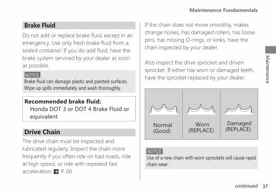
If the chain does not move smoothly, makes strange noises, has damaged rollers, has loose pins, has missing O-rings, or kinks, have the chain inspected by your dealer.
Also inspect the drive sprocket and driven sprocket. If either has worn or damaged teeth, have the sprocket replaced by your dealer.
NOTICE Use of a new chain with worn sprockets will cause rapid chain wear.
Normal(Good)
Worn(REPLACE)
Damaged(REPLACE)Drive Chain
The drive chain must be inspected and lubricated regularly. Inspect the chain more frequently if you often ride on bad roads, ride at high speed, or ride with repeated fast acceleration. 2 P. 60
Recommended brake fluid: Honda DOT 3 or DOT 4 Brake Fluid or equivalent
continued
38
Maintenance
Maintenance Fundamentals
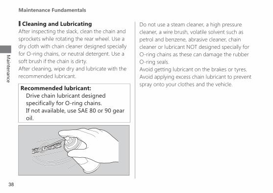
Do not use a steam cleaner, a high pressure cleaner, a wire brush, volatile solvent such as petrol and benzene, abrasive cleaner, chain cleaner or lubricant NOT designed specially for O-ring chains as these can damage the rubber O-ring seals.Avoid getting lubricant on the brakes or tyres. Avoid applying excess chain lubricant to prevent spray onto your clothes and the vehicle.
# Cleaning and LubricatingAfter inspecting the slack, clean the chain and sprockets while rotating the rear wheel. Use a dry cloth with chain cleaner designed specially for O-ring chains, or neutral detergent. Use a soft brush if the chain is dirty.After cleaning, wipe dry and lubricate with the recommended lubricant.
Recommended lubricant: Drive chain lubricant designed specifically for O-ring chains. If not available, use SAE 80 or 90 gear oil.

39
Maintenance
Maintenance Fundamentals
Crankcase BreatherService more frequently when riding in rain, at full throttle, or after the vehicle is washed or overturned. Service if the deposit level can be seen in the transparent section of the drain tube.If the drain tube is overflows, the air filter may become contaminated with engine oil causing poor engine performance. 2 P. 66
Tyres (Inspecting/Replacing)
# Checking the Air PressureVisually inspect your tyres and use an airpressure gauge to measure the air pressure at least once a month or any time you think the tyres look low. Always check air pressure when your tyres are cold.
# Inspecting for Abnormal WearInspect the tyres for signs of abnormal wear on the contact surface.
continued
# Inspecting for DamageInspect the tyres for cuts, slits, or cracks that exposes fabric or cords, or nails or other foreign objects embedded in the side of the tyre or the tread. Also inspect for any unusual bumps or bulges in the side walls of the tyres.

40
Maintenance
Maintenance Fundamentals
WARNINGRiding on tyres that are excessively worn or improperly inflated can cause a crash in which you can be seriously hurt or killed.
Follow all instructions in this owner’s manual regarding tyre inflation and maintenance.
# Inspecting Tread DepthInspect the tread wear indicators. If they become visible, replace the tyres immediately.For safe riding, you should replace the tyres when the minimum tread depth is reached.
Have your tyres replaced by your dealer.For recommended tyres air pressure and minimum tread depth, see “Specifications.” 2 P. 96Follow these guidelines whenever you replace tyres.
z Use the recommended tyres or equivalents of the same size, construction, speed rating, and load range.
Wear indicatorlocation mark
41
Maintenance
Maintenance Fundamentals
WARNINGInstalling improper tyres on your vehicle can adversely affect handling and stability, and can cause a crash in which you can be seriously hurt or killed.
Always use the size and type of tyres recommended in this owner’s manual.
z Do not install a tube inside a tubeless tyre on this vehicle. Excessive heat build-up can cause the tube to burst.
z Use only tubeless tyres on this vehicle. The rims are designed for tubeless tyres, and during hard acceleration or braking, a tube-type tyre could slip on the rim and cause the tyre to rapidly deflate.
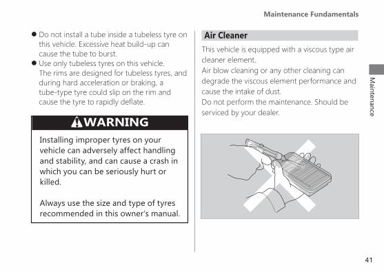
Air CleanerThis vehicle is equipped with a viscous type air cleaner element.Air blow cleaning or any other cleaning candegrade the viscous element performance and cause the intake of dust.Do not perform the maintenance. Should be serviced by your dealer.
42
Maintenance
Tool
The tool kit is stored under the seat. 2 P. 25
You can perform some roadside repairs, minor adjustments and parts replacement with the provided tools.
z 14 x 17 mm Open end wrench z Spark plug wrench z Standard/Philips screwdriver z Fuse puller
43
Maintenance
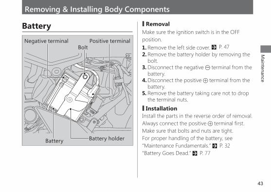
Battery holderBattery
Positive terminalNegative terminalBolt
Battery # RemovalMake sure the ignition switch is in the OFF position.1. Remove the left side cover. 2 P. 472. Remove the battery holder by removing the
bolt.3. Disconnect the negative terminal from the
battery.4. Disconnect the positive terminal from the
battery.5. Remove the battery taking care not to drop
the terminal nuts.
# InstallationInstall the parts in the reverse order of removal. Always connect the positive terminal first. Make sure that bolts and nuts are tight.For proper handling of the battery, see “Maintenance Fundamentals.” 2 P. 32“Battery Goes Dead.” 2 P. 77
Removing & Installing Body Components
44
Maintenance
Removing & Installing Body Components ► Drive Chain Case
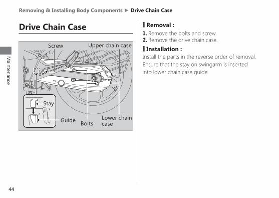
Drive Chain Case # Removal :1. Remove the bolts and screw.2. Remove the drive chain case.
# Installation :Install the parts in the reverse order of removal. Ensure that the stay on swingarm is inserted into lower chain case guide.
Lower chain case
Upper chain case
Bolts
Screw
Stay
Guide

45
Maintenance
Removing & Installing Body Components ► Headlight Case
Headlight Case # Removal :1. Remove the screws.2. Remove the headlight case by releasing the
snap fit clips and disconnect the connector.
# Installation :Install the parts in the reverse order of removal.
Screws
Headlight case ConnectorScrews
Snap fit clips
46
Maintenance
Removing & Installing Body Components ► Seat
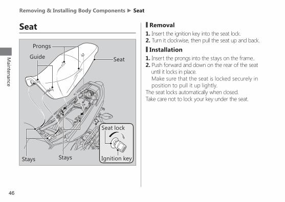
Prongs
Guide Seat
StaysStays
Seat # Removal1. Insert the ignition key into the seat lock.2. Turn it clockwise, then pull the seat up and back.
# Installation1. Insert the prongs into the stays on the frame..2. Push forward and down on the rear of the seat
until it locks in place. Make sure that the seat is locked securely in
position to pull it up lightly.The seat locks automatically when closed.Take care not to lock your key under the seat.
Seat lock
Ignition key

47
Maintenance
Removing & Installing Body Components ► Side Cover
Side Cover The right and left side covers can be removed in the same manner.
# Removal :1. Remove the seat. 2 P. 462. Remove the screw A, screw B and screw C.3. Remove the prongs from the grommets.4. Remove the side cover.
# Installation :Install the parts in the reverse order of removal.
Screw B
Screw A
Screw C
Prongs
Grommets
Left side cover
48
Maintenance
Spark Plug
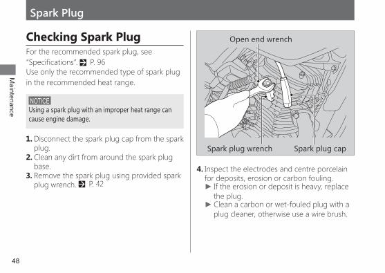
Checking Spark PlugFor the recommended spark plug, see “Specifications”. 2 P. 96Use only the recommended type of spark plug in the recommended heat range.
NOTICE Using a spark plug with an improper heat range can cause engine damage.
1. Disconnect the spark plug cap from the spark plug.
2. Clean any dirt from around the spark plug base.
3. Remove the spark plug using provided spark plug wrench. 2 P. 42
4. Inspect the electrodes and centre porcelain for deposits, erosion or carbon fouling.
► If the erosion or deposit is heavy, replace the plug. ►Clean a carbon or wet-fouled plug with a plug cleaner, otherwise use a wire brush.
Spark plug wrench
Open end wrench
Spark plug cap
49
Maintenance
Spark Plug ► Checking Spark Plug
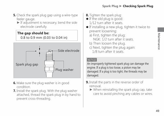
The gap should be: 0.8 to 0.9 mm (0.03 to 0.04 in)
NOTICE An improperly tightened spark plug can damage the engine. If a plug is too loose, a piston may be damaged. If a plug is too tight, the threads may be damaged.
9. Install the parts in the reverse order of removal.
►When reinstalling the spark plug cap, take care to avoid pinching any cables or wires.
Side electrode
Spark plug gapPlug washer
5. Check the spark plug gap using a wire-type feeler gauge.
► If adjustment is necessary, bend the side electrode carefully.
6. Make sure the plug washer is in good condition.
7. Install the spark plug. With the plug washer attached, thread the spark plug in by hand to prevent cross-threading.
8. Tighten the spark plug: z If the old plug is good: 1/12 turn after it seats.
z If installing a new plug, tighten it twice to prevent loosening: a) First, tighten the plug: NGK: 1/2 turn after it seats. b) Then loosen the plug. c) Next, tighten the plug again: 1/8 turn after it seats.

50
Maintenance
Engine Oil
Checking the Engine Oil1. If the engine is cold, idle the engine for 3 to 5
minutes.2. Turn the ignition switch to the OFF position
and wait 2 to 3 minutes.3. Place your vehicle on its centre stand on a
firm, level surface.4. Remove the oil fill cap/dipstick and wipe it
clean.5. Insert the oil fill cap/dipstick until it seats, but
don’t screw it in.6. Check that the oil level is between the upper
level and lower level marks on the oil fill cap/dipstick.
7. Securely install the oil fill cap/dipstick.
Oil fill cap/dipstick
Lower level
Upper level

51
Maintenance
Engine Oil ► Adding Engine Oil
For the recommended oil and oil selection guidelines, see “Maintenance Fundamentals”. 2 P. 36
Changing Engine OilChanging the oil requires special tools. We recommend that you have your vehicle serviced by your dealer.1. If the engine is cold, idle the engine for 3 to 5
minutes.2. Turn the ignition switch to the OFF position
and wait for 2 to 3 minutes.3. Place your vehicle on its centre stand on a
firm, level surface.4. Place a drain pan under the drain bolt.
Adding Engine OilIf the engine oil is below or near the lower level mark, add the recommended engine oil. 2 P. 36, 961. Remove the oil fill cap/dipstick. Add the
recommended oil until it reaches the upper level mark.
► Place your vehicle on its centre stand on a firm, level surface when checking the oil level. ►Do not overfill above the upper level mark. ►Make sure no foreign objects enter the oil filler opening. ►Wipe up any spills immediately.
2. Securely reinstall the oil fill cap/dipstick.
NOTICE Overfilling with oil or operating with insufficient oil can cause damage to your engine. Do not mix different brands and grades of oil. The may affect lubrication and clutch operation.
continued
52
Maintenance
Engine Oil ► Changing Engine Oil
Sealing washer
Oil drain bolt
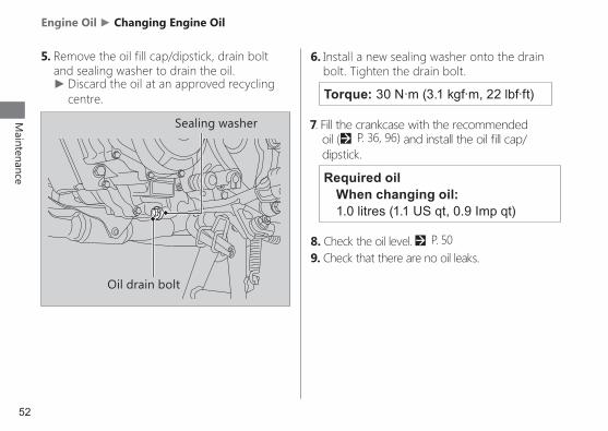
5. Remove the oil fill cap/dipstick, drain bolt and sealing washer to drain the oil.
►Discard the oil at an approved recycling centre.
6. Install a new sealing washer onto the drain bolt. Tighten the drain bolt.
Torque: 30 N·m (3.1 kgf·m, 22 lbf·ft)
Required oilWhen changing oil: 1.0 litres (1.1 US qt, 0.9 Imp qt)
7. Fill the crankcase with the recommended oil (2 P. 36, 96) and install the oil fill cap/dipstick.
8. Check the oil level. 2 P. 509. Check that there are no oil leaks.
53
Maintenance
Brakes
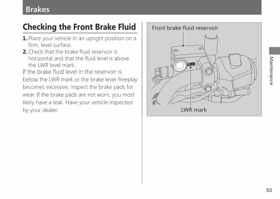
Checking the Front Brake Fluid1. Place your vehicle in an upright position on a
firm, level surface.2. Check that the brake fluid reservoir is
horizontal and that the fluid level is above the LWR level mark.
If the brake fluid level in the reservoir is below the LWR mark or the brake lever freeplay becomes excessive, inspect the brake pads for wear. If the brake pads are not worn, you most likely have a leak. Have your vehicle inspected by your dealer.
Front brake fluid reservoir
LWR mark
54
Maintenance
Brakes ► Inspecting the Front Brake Pads
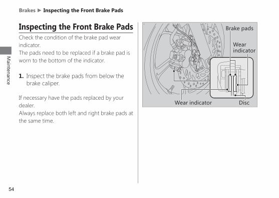
Inspecting the Front Brake PadsCheck the condition of the brake pad wear indicator. The pads need to be replaced if a brake pad is worn to the bottom of the indicator.
1. Inspect the brake pads from below the brake caliper.
If necessary have the pads replaced by your dealer.Always replace both left and right brake pads at the same time.
Wear indicator
Wear indicator Disc
Brake pads
55
Maintenance
Brakes ► Inspecting the Rear Brake Pedal Freeplay
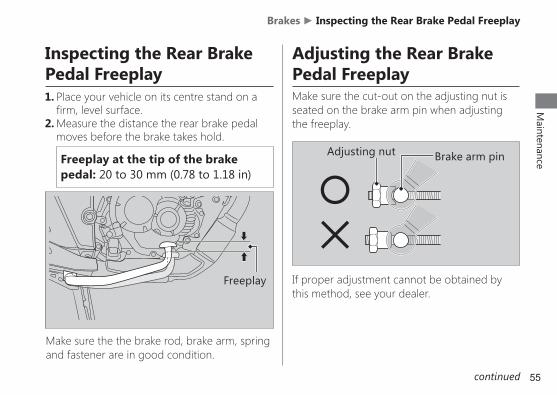
Inspecting the Rear Brake Pedal Freeplay1. Place your vehicle on its centre stand on a
firm, level surface.2. Measure the distance the rear brake pedal
moves before the brake takes hold.
Freeplay at the tip of the brake pedal: 20 to 30 mm (0.78 to 1.18 in)
Freeplay
Adjusting nut Brake arm pin
Make sure the the brake rod, brake arm, spring and fastener are in good condition.
Adjusting the Rear Brake Pedal FreeplayMake sure the cut-out on the adjusting nut is seated on the brake arm pin when adjusting the freeplay.
If proper adjustment cannot be obtained by this method, see your dealer.
continued

56
Maintenance
Brakes ► Adjusting the Rear Brake Pedal Freeplay
3. Push the brake arm to confirm that there is a gap between the rear brake adjusting nut and brake arm pin.
After adjustment, confirm the freeplay of the brake pedal.Make sure the brake rod, brake arm, spring and fastener are in good condition.
NOTICE Do not turn the adjuster beyond its natural limits.
1. Adjust by turning the rear brake adjusting nut a half-turn at a time.
2. Apply the brake several times and check for free wheel rotation after the brake pedal is released.
Adjustingnut
Brake arm
Push
Brake arm pin
Gap
Decrease Freeplay
Increase Freeplay
Brake arm pin
Adjustingnut
57
Maintenance
Brakes ► Inspecting the Rear Brake Shoe Wear
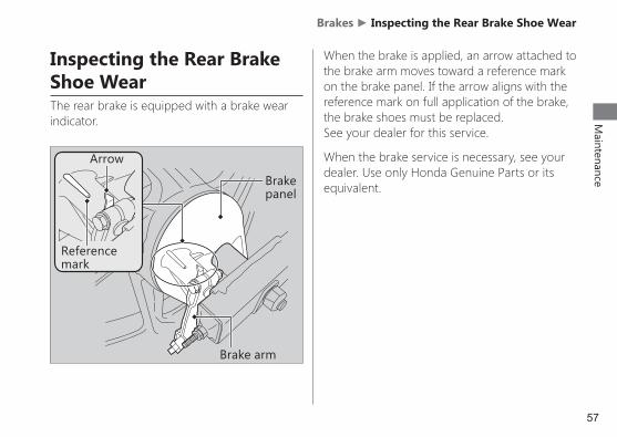
Inspecting the Rear Brake Shoe WearThe rear brake is equipped with a brake wear indicator.
When the brake is applied, an arrow attached to the brake arm moves toward a reference mark on the brake panel. If the arrow aligns with the reference mark on full application of the brake, the brake shoes must be replaced. See your dealer for this service.
When the brake service is necessary, see your dealer. Use only Honda Genuine Parts or its equivalent.Brake
panel
Brake arm
Reference mark
Arrow
58
Maintenance
Brakes ► Adjusting the Brakelight Switch
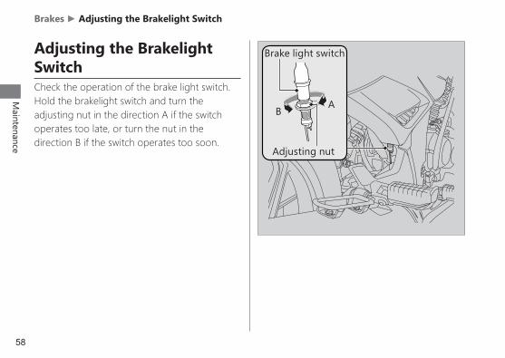
Adjusting the Brakelight SwitchCheck the operation of the brake light switch.Hold the brakelight switch and turn theadjusting nut in the direction A if the switchoperates too late, or turn the nut in thedirection B if the switch operates too soon.
Adjusting nut
BA
Brake light switch
59
Maintenance
Side Stand
Checking the Side Stand
Side stand spring
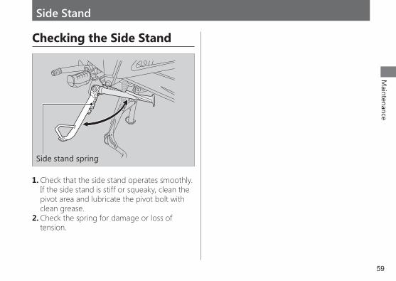
1. Check that the side stand operates smoothly. If the side stand is stiff or squeaky, clean the pivot area and lubricate the pivot bolt with clean grease.
2. Check the spring for damage or loss of tension.
60
Maintenance
Drive Chain
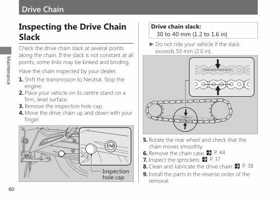
Inspecting the Drive Chain SlackCheck the drive chain slack at several points along the chain. If the slack is not constant at all points, some links may be kinked and binding.Have the chain inspected by your dealer.1. Shift the transmission to Neutral. Stop the
engine.2. Place your vehicle on its centre stand on a
firm, level surface.3. Remove the inspection hole cap.4. Move the drive chain up and down with your
finger.
Drive chain slack: 30 to 40 mm (1.2 to 1.6 in)
►Do not ride your vehicle if the slack exceeds 50 mm (2.0 in).
Inspection hole cap
5. Rotate the rear wheel and check that the chain moves smoothly.
6. Remove the chain case. 2 P. 447. Inspect the sprockets. 2 P. 378. Clean and lubricate the drive chain. 2 P. 389. Install the parts in the reverse order of the
removal.

61
Maintenance
Drive Chain ► Adjusting the Drive Chain Slack
Lock nutAdjusting nut
Adjusting the Drive Chain SlackAdjusting the chain requires special tools.Have the drive chain slack adjusted by your dealer.1. Shift the transmission to Neutral. Stop the
engine.2. Place your vehicle on its centre stand on a
firm, level surface.3. Loosen the rear axle nut.4. Loosen the lock nuts on both adjusting bolts.
Adjusting nut
Lock nut
Axle nut
5. Turn both adjusting nuts an equal number of turns until the correct drive chain slack is obtained. Turn the adjusting nuts clockwise to tighten the chain. Turn the adjusting nuts counterclockwise and push the rear wheel toward the front to provide more slack. Adjust the slack at a point midway between the front sprocket and the rear sprocket. Check the drive chain slack. 2 P. 60
6. Check rear axle alignment by making sure the end of the chain adjuster aligns with the scale graduations on both sides of the swingarm.
Rear edge of adjusting slot
Rear edge of adjusting slot
Scale graduations
Scale graduations
continued
62
Maintenance
Drive Chain ► Adjusting the Drive Chain Slack
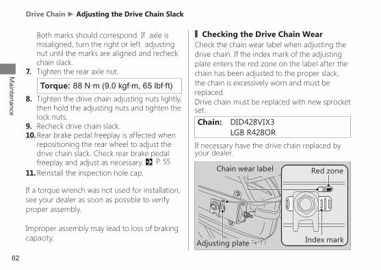
Torque: 88 N·m (9.0 kgf·m, 65 lbf·ft)
Both marks should correspond. If axle is misaligned, turn the right or left adjusting nut until the marks are aligned and recheck chain slack.
7. Tighten the rear axle nut.
8. Tighten the drive chain adjusting nuts lightly, then hold the adjusting nuts and tighten the lock nuts.
9. Recheck drive chain slack.10. Rear brake pedal freeplay is affected when
repositioning the rear wheel to adjust the drive chain slack. Check rear brake pedal freeplay and adjust as necessary. 2 P. 55
11. Reinstall the inspection hole cap.
If a torque wrench was not used for installation, see your dealer as soon as possible to verify proper assembly.
Improper assembly may lead to loss of braking capacity.
# Checking the Drive Chain WearCheck the chain wear label when adjusting the drive chain. If the index mark of the adjusting plate enters the red zone on the label after the chain has been adjusted to the proper slack, the chain is excessively worn and must be replaced.Drive chain must be replaced with new sprocket set.Chain: DID428VIX3 LGB R428OR
Red zone
Index mark
Chain wear label
If necessary have the drive chain replaced by your dealer.
Adjusting plate

63
Maintenance
Clutch
Checking the Clutch# Checking the Clutch Lever Freeplay
Check the clutch lever freeplay.
Freeplay at the clutch lever: 10 to 20 mm (0.39 to 0.79 in)
Check the clutch cable for kinks or signs of wear. If necessary have it replaced by your dealer.Lubricate the clutch cable with a commercially available cable lubricant to prevent premature wear and corrosion.
NOTICE Improper freeplay adjustment can cause premature clutch wear.Clutch leverFreeplay
64
Maintenance
Clutch ► Adjusting the Clutch Lever Freeplay
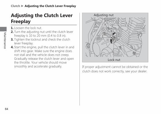
Adjusting the Clutch Lever Freeplay1. Loosen the lock nut.2. Turn the adjusting nut until the clutch lever
freeplay is 10 to 20 mm (0.4 to 0.8 in).3. Tighten the locknut and check the clutch
lever freeplay.4. Start the engine, pull the clutch lever in and
shift into gear. Make sure the engine does not stall and the vehicle does not creep. Gradually release the clutch lever and open the throttle. Your vehicle should move smoothly and accelerate gradually. If proper adjustment cannot be obtained or the
clutch does not work correctly, see your dealer.
Adjusting nut
Lock nut
+
-
65
Maintenance
Throttle
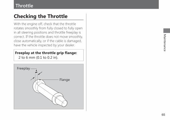
Checking the ThrottleWith the engine off, check that the throttle rotates smoothly from fully closed to fully open in all steering positions and throttle freeplay is correct. If the throttle does not move smoothly, close automatically, or if the cable is damaged, have the vehicle inspected by your dealer.
Freeplay at the throttle grip flange: 2 to 6 mm (0.1 to 0.2 in).
Flange
Freeplay
66
Maintenance
Crankcase Breather
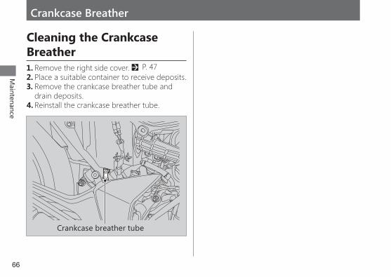
Cleaning the Crankcase Breather1. Remove the right side cover. 2 P. 472. Place a suitable container to receive deposits.3. Remove the crankcase breather tube and
drain deposits.4. Reinstall the crankcase breather tube.
Crankcase breather tube
67
Maintenance
Other Adjustments
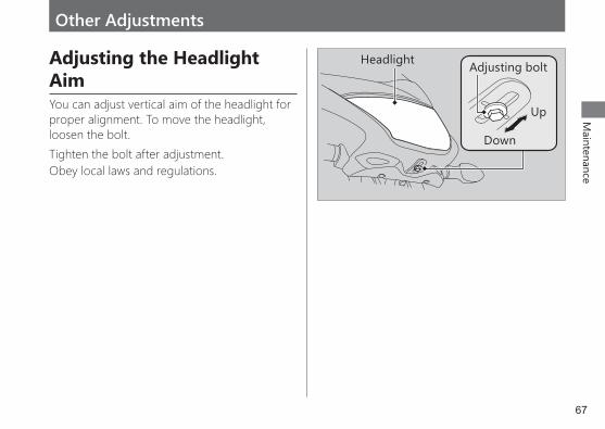
Adjusting the Headlight AimYou can adjust vertical aim of the headlight for proper alignment. To move the headlight, loosen the bolt.Tighten the bolt after adjustment.Obey local laws and regulations.
Headlight
Up
Down
Adjusting bolt
68
Maintenance
Other Adjustments ► Adjusting the Rear Suspension
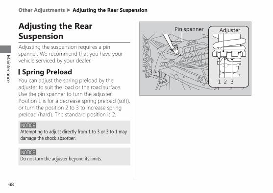
Adjusting the Rear SuspensionAdjusting the suspension requires a pin spanner. We recommend that you have your vehicle serviced by your dealer.
▌Spring PreloadYou can adjust the spring preload by the adjuster to suit the load or the road surface. Use the pin spanner to turn the adjuster. Position 1 is for a decrease spring preload (soft), or turn the position 2 to 3 to increase spring preload (hard). The standard position is 2.
NOTICE Attempting to adjust directly from 1 to 3 or 3 to 1 may damage the shock absorber.
NOTICE Do not turn the adjuster beyond its limits.
Pin spanner Adjuster
1 2 3

Troubleshooting
Engine Will Not Start .............................................. P. 70Warning Indicators On or Flashing .............P. 71
PGM-FI (Programmed Fuel Injection) Malfunction Indicator Lamp (MIL) ........................P. 71
ABS (Anti-lock Brake System) Indicator ..............P. 71Tyre Puncture ..................................................................P. 72Electrical Trouble..........................................................P. 77
Battery Goes Dead...................................................................P. 77Burned-out Light Bulb..........................................................P. 77Blown Fuse ........................................................................................P. 80
Unstable Engine Operation Occur Intermittently ...............................................................P. 82
70
Troubleshooting
Engine Will Not Start
Starter Motor Operates But Engine Does Not StartCheck the following items:
z Check the correct engine starting sequence. 2 P. 20
z Check that there is petrol in the fuel tank. z Check if the PGM-FI malfunction indicator lamp (MIL) is on.
u If the indicator lamp is on, contact your dealer as soon as possible.
Starter Motor Does Not OperateCheck the following items:
z Check the correct engine starting sequence. 2 P. 20
z Make sure engine stop switch is in the (Run) position. 2 P. 18
z Check for a blown fuse. 2 P. 80 z Check for a loose battery connection (2 P. 43) or battery terminal corrosion (2 P. 33).
z Check the condition of the battery. 2 P. 33If the problem continues, have your vehicle inspected by your dealer.

71
TroubleshootingWarning Indicators On or Flashing
PGM-FI (Programmed Fuel Injection) Malfunction Indicator Lamp (MIL)If the indicator comes on while riding, you may have a serious problem with the PGM-FI system. Reduce speed and have your vehicle inspected by your dealer as soon as possible.
ABS (Anti-lock Brake System) IndicatorIf the indicator operates in one of the following ways, you may have a serious problem with the ABS. Reduce your speed and have your vehicle inspected by your dealer as soon as possible.
z Indicator comes on or starts flashing while riding.
z Indicator does not come on when the ignition switch is in the ON position.
z Indicator does not go off at speeds above 5 km/h (3 mph).
If the ABS indicator stays on, your brakes will continue to work as a conventional system, but without the anti-locking function.
The ABS indicator may flash if you turn the rear wheel while the rear wheel is lifted off the ground. In this case, turn the ignition switch to the OFF position, and then to the ON position again. The ABS indicator will go off after your speed reaches 5 km/h (3 mph).
72
Troubleshooting
Tyre Puncture
Repairing a puncture or removing a wheel requires special tools and technical expertise. We recommend you have this type of service performed by your dealer.After an emergency repair, always have the tyre inspected/replaced by your dealer.
Emergency Repair Using a Tyre Repair KitIf your tyre has a minor puncture, you can make an emergency repair using a tubeless tyre repair kit.Follow the instructions provided with the emergency tyre repair kit.Riding your vehicle with a temporary tyre repair is very risky. Do not exceed 50 km/h (30 mph). Have the tyre replaced by your dealer as soon as possible.
Removing Wheels
Follow these procedures if you need to remove a wheel in order to repair a puncture.
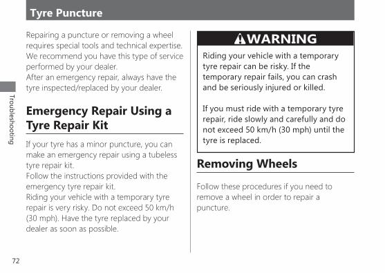
WARNINGRiding your vehicle with a temporary tyre repair can be risky. If the temporary repair fails, you can crash and be seriously injured or killed.
If you must ride with a temporary tyre repair, ride slowly and carefully and do not exceed 50 km/h (30 mph) until the tyre is replaced.

73
TroubleshootingTyre Puncture u Removing Wheels
## Front WheelRemoval1. Place your vehicle on its centre stand on a
firm, level surface.2. Support your vehicle securely and raise
the front wheel off the ground using a maintenance stand or a hoist.
3. Remove the speedometer cable by pushing the tab.
4. Remove the front axle nut.5. Remove the front axle shaft, front wheel,
side collar and speedometer gear box. uAvoid getting grease, oil, or dirt on the disc or pad surfaces. uDo not pull the brake lever while the front wheel is removed.
Speedometer cable
Speedometer gear box
Front axle shaft
Side collar
Front axle nut
continued
Tab
74
Troubleshooting
Tyre Puncture u Removing Wheels
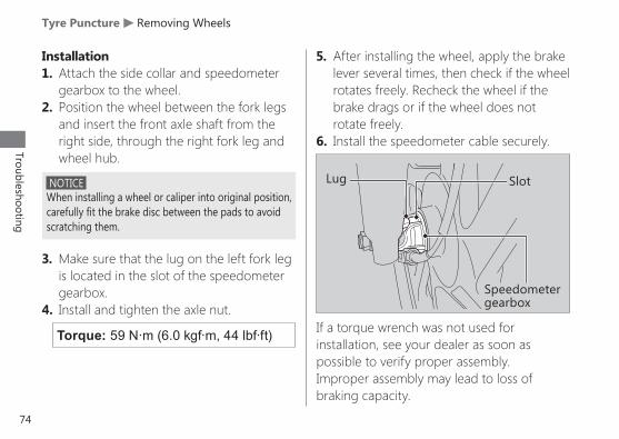
Installation1. Attach the side collar and speedometer
gearbox to the wheel.2. Position the wheel between the fork legs
and insert the front axle shaft from the right side, through the right fork leg and wheel hub.
NOTICE When installing a wheel or caliper into original position,carefully fit the brake disc between the pads to avoidscratching them.
Torque: 59 N·m (6.0 kgf·m, 44 lbf·ft)
5. After installing the wheel, apply the brake lever several times, then check if the wheel rotates freely. Recheck the wheel if the brake drags or if the wheel does not rotate freely.
6. Install the speedometer cable securely.
3. Make sure that the lug on the left fork leg is located in the slot of the speedometer gearbox.
4. Install and tighten the axle nut.If a torque wrench was not used for installation, see your dealer as soon as possible to verify proper assembly. Improper assembly may lead to loss of braking capacity.
Lug Slot
Speedometer gearbox
75
TroubleshootingTyre Puncture u Removing Wheels
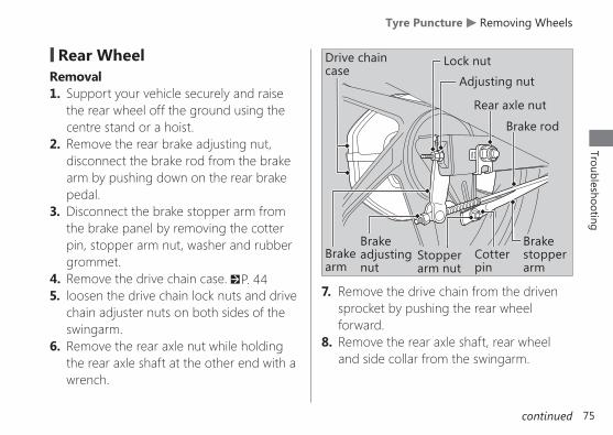
7. Remove the drive chain from the driven sprocket by pushing the rear wheel forward.
8. Remove the rear axle shaft, rear wheel and side collar from the swingarm.
## Rear WheelRemoval1. Support your vehicle securely and raise
the rear wheel off the ground using the centre stand or a hoist.
2. Remove the rear brake adjusting nut, disconnect the brake rod from the brake arm by pushing down on the rear brake pedal.
3. Disconnect the brake stopper arm from the brake panel by removing the cotter pin, stopper arm nut, washer and rubber grommet.
4. Remove the drive chain case. 2 P. 445. loosen the drive chain lock nuts and drive
chain adjuster nuts on both sides of the swingarm.
6. Remove the rear axle nut while holding the rear axle shaft at the other end with a wrench.
Adjusting nut
Cotter pin
Brake stopperarm
Brakeadjustingnut
Brakearm
Lock nut
Stopper arm nut
Rear axle nut
Brake rod
Drive chain case
continued

76
Troubleshooting
Tyre Puncture u Removing Wheels
Installation1. Install the side collar into rear wheel.2. Place the rear wheel between the swingarm
and install the drive chain over the driven sprocket.
3. Insert the rear axle shaft from the left side, through the left swingarm, wheel hub and brake panel.
4. Temporarily tighten the rear axle nut.5. Reassemble the brake stopper arm and
tighten the stopper arm nut.
6. Connect the brake rod to the brake arm.7. Adjust the drive chain. 2 P. 618. Adjust the rear brake freeplay. 2 P. 559. Tighten the rear axle nut.
10. Reassemble the drive chain case. 2 P. 4411. After installing the wheel, apply the brake
pedal several times, then check if the wheel rotates freely. Recheck the wheel if the brake drags or if the wheel does not rotate freely.
If a torque wrench was not used for installation, see your dealer as soon as possible to verify proper assembly.Improper assembly may lead to loss of braking capacity.A used cotter pin may not effectively secure a fastener. Always replace a used cotter pin with a new one.Torque: 22 N·m (2.2 kgf·m, 16 lbf·ft)
Torque: 88 N·m (9.0 kgf·m, 65 lbf·ft)
Drive chain Adjusting nut
Lock nutRear axle shaft

77
TroubleshootingElectrical Trouble
Battery Goes DeadCharge the battery using a motorcycle battery charger.Remove the battery from the vehicle before charging.Do not use an automobile-type battery charger, as these can overheat a motorcycle battery and cause permanent damage.If the battery does not recover after recharging, contact your dealer.
NOTICE Jump starting using an automobile battery can damage your vehicle’s electrical system and is not recommended.
Burned-out Light BulbFollow the procedure below to replace a burned-out light bulb.Turn the ignition switch to the OFF or LOCK position.Allow the bulb to cool before replacing it.Do not use bulbs other than those specified.Check the replacement bulb for correct operation before riding.
For the light bulb wattage, see “Specifications.“ 2 P. 97
78
Troubleshooting
Electrical Trouble u Burned-out Light Bulb
## Headlight bulb
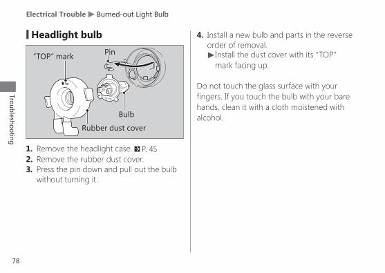
1. Remove the headlight case. 2 P. 452. Remove the rubber dust cover.3. Press the pin down and pull out the bulb
without turning it.
Rubber dust cover
“TOP” mark Pin
Bulb
4. Install a new bulb and parts in the reverse order of removal. u Install the dust cover with its “TOP” mark facing up.
Do not touch the glass surface with your fingers. If you touch the bulb with your bare hands, clean it with a cloth moistened with alcohol.
79
TroubleshootingElectrical Trouble u Burned-out Light Bulb
# Brakelight/Taillight Bulb # Front/Rear Turn Signal Bulb
Turn signal lens
Socket
ScrewBulb
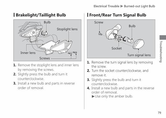
1. Remove the stoplight lens and inner lens by removing the screws.
2. Slightly press the bulb and turn it counterclockwise.
3. Install a new bulb and parts in reverse order of removal.
1. Remove the turn signal lens by removing the screw.
2. Turn the socket counterclockwise, and remove it.
3. Slightly press the bulb and turn it counterclockwise.
4. Install a new bulb and parts in the reverse order of removal. uUse only the amber bulb.
Stoplight lens
Screws
Bulb
Inner lens
80
Troubleshooting
Electrical Trouble u Blown Fuse
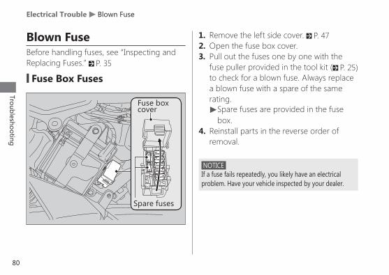
Blown FuseBefore handling fuses, see “Inspecting andReplacing Fuses.” 2 P. 35
## Fuse Box Fuses
NOTICE If a fuse fails repeatedly, you likely have an electrical problem. Have your vehicle inspected by your dealer.
1. Remove the left side cover. 2 P. 472. Open the fuse box cover.3. Pull out the fuses one by one with the
fuse puller provided in the tool kit (2 P. 25) to check for a blown fuse. Always replace a blown fuse with a spare of the same rating. uSpare fuses are provided in the fuse box.
4. Reinstall parts in the reverse order of removal.
Spare fuses
Fuse box cover

81
TroubleshootingElectrical Trouble u Blown Fuse
## Main Fuse
NOTICE If a fuse fails repeatedly, you likely have an electrical problem. Have your vehicle inspected by your dealer.
1. Remove the left side cover. 2 P. 472. Disconnect the negative - terminal from
the battery. 2 P. 433. Pull out the starter magnetic switch.4. Disconnect the wire connector of the
starter magnetic switch..5. Pull the main fuse out and check for a
blown fuse. Always replace a blown fuse with a spare fuse of the same rating. uSpare main fuse (20 A) is provided below the starter magnetic switch.
6. Reinstall parts in the reverse order of removal.
Starter magnetic switch
Wire connectorMain fuse
Spare main fuse
82
Troubleshooting
Unstable Engine Operation Occurs Intermittently
If the fuel pump filter is clogged, unstable engine operation will occur intermittently while riding.Even if this symptom occurs, you can continue to ride your vehicle.If unstable engine operation occurs even if sufficient fuel is available, have your vehicle inspected by your dealer as soon as possible.

Keys ..........................................................................................P. 84Instruments, Controls, & Other Features ................................................................ P. 85Caring for Your Vehicle ...........................................P. 86Storing Your Vehicle ..................................................P. 89Transporting Your Vehicle ....................................P. 90You & the Environment .......................................... P. 91Serial Numbers............................................................... P. 92Fuels Containing Alcohol ...................................... P. 93Catalytic Converters ..................................................P. 94
Information
84
Information
Keys
KeysIgnition key
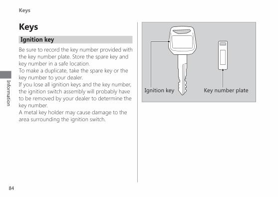
Be sure to record the key number provided with the key number plate. Store the spare key and key number in a safe location.To make a duplicate, take the spare key or the key number to your dealer.If you lose all ignition keys and the key number, the ignition switch assembly will probably have to be removed by your dealer to determine the key number.A metal key holder may cause damage to thearea surrounding the ignition switch.
Key number plateIgnition key
85
Information
Instruments, Controls, & Other Features
Instruments, Controls, & Other FeaturesIgnition Switch
Leaving the ignition switch in the ON position with the engine stopped will drain the battery. Do not turn the key while riding.
TripmeterThe tripmeter returns to 0.0 when the read-out exceeds 999.9.
Engine Stop SwitchDo not use the engine stop switch except in an emergency. Doing so when riding will cause the engine to suddenly turn off, making riding unsafe. If you stop the engine using the engine stop switch, turn the ignition switch to the OFF position. Failing to do so will drain the battery.
OdometerThe odometer returns to 0 when the read-out exceeds 99,999.9.
Document BagThe owner’s manual, registration, and insurance information can be stored in the plastic document bag located under the seat.
Ignition Cut-off SystemA banking (lean angle) sensor automatically stops the engine and fuel pump if the vehicle falls over. To reset the sensor, you must turn the ignition switch to the OFF position and back to the ON position before the engine can be restarted.

86
Information
Caring for Your Vehicle
Caring for Your VehicleFrequent cleaning and polishing is important to ensure the life of your Honda. A clean vehicle makes it easier to spot potential problems.In particular, seawater and salts used to prevent ice on roads promote the formation of corrosion. Always wash your vehicle thoroughly after riding on coastal or treated roads.
WashingAllow the engine, muffler, brakes, and other high-temperature parts to cool before washing.1. Rinse your vehicle thoroughly using a low
pressure garden hose to remove loose dirt.2. If necessary, use a sponge or a soft towel
with mild cleaner to remove road grime. u Clean the headlight lens, panels, and other plastic components with extra care to avoid scratching them. Avoid directing water into the air cleaner, muffler, and electrical parts.
3. Thoroughly rinse your vehicle with plenty of clean water and dry with a soft, clean cloth.
4. After the vehicle dries, lubricate any moving parts.
u Make sure that no lubricant spills onto the brakes or tyres. Brake discs, pads, drum or shoes contaminated with oil will suffer greatly reduced braking effectiveness and can lead to a crash.
5. Lubricate the drive chain immediately after washing and drying the vehicle.
6. Apply a coat of wax to prevent corrosion. u Avoid products that contain harsh detergents or chemical solvents. These can damage the metal, paint, and plastic on your vehicle. Keep the wax clear of the tyres and brakes. u If your vehicle has any matte painted parts, do not apply a coat of wax to the matte painted surface.
87
Information
Caring for Your Vehicle
## Washing PrecautionsFollow these guidelines when washing:
z Do not use high-pressure washers: u High-pressure water cleaners can damage moving parts and electrical parts, rendering them inoperable. u Water in the air intake can be drawn into the throttle body and/or enter the air cleaner.
z Do not direct water at the muffler: u Water in the muffler can prevent starting and causes rust in the muffler.
z Dry the brakes: u Water adversely affects braking effectiveness. After washing, apply the brakes intermittently at low speed to help dry them.
z Do not direct water under the seat: u Water under the seat can damage your documents and other belongings.
z Do not direct water at the air cleaner: u Water in the air cleaner can prevent the engine from starting.
z Do not direct water near the headlight: u The headlight’s inside lens may fog temporarily after washing or while riding in rain. This does not impact the headlight function. u Any condensation inside the headlight should dissipate after a few minutes of running the engine with the headlight on. However, if you see a large amount of water or ice accumulated inside the lens(es), have your vehicle inspected by your dealer.
z Do not use wax or polishing compounds on matte painted surface:
u Use a soft cloth or sponge, plenty of water, and a mild detergent to clean matte painted surfaces. Dry with a soft clean cloth.
continued
88
Information
Caring for Your Vehicle
Aluminium ComponentsAluminium will corrode from contact with dirt, mud, or road salt. Clean aluminium parts regularly and follow these guidelines to avoid scratches:
z Do not use stiff brushes, steel wool, or cleaners containing abrasives.
z Avoid riding over or scraping against curbs.
PanelsFollow these guidelines to prevent scratches and blemishes:
z Wash gently using a soft sponge and plenty of water.
z To remove stubborn stains, use diluted detergent and rinse thoroughly with plenty of water.
z Avoid getting petrol, brake fluid, or detergents on the instruments, panels or headlight.
Exhaust Pipe and MufflerWhen the exhaust pipe and muffler are painted, do not use a commercially available abrasive kitchen cleaning compound. Use a neutral detergent to clean the painted surface on the exhaust pipe and muffler. If you are not sure if your exhaust pipe and muffler are painted, contact your dealer.
89
Information
Storing Your Vehicle
Storing Your VehicleIf you store your vehicle outdoors, you should consider using a full-body vehicle cover.If you won’t be riding for an extended period, follow these guidelines:
z Wash your vehicle and wax all painted surfaces (except matte painted surfaces). Coat chrome pieces with rust-inhibiting oil.
z Lubricate the drive chain. 2 P. 38 z Place your vehicle on its centre stand and position a block so that both tyres are off the ground.
z After rain, remove the body cover and allow the vehicle to dry.
z Remove the battery (2 P. 43) to prevent discharge. Fully charge the battery and then place it in a shaded, well-ventilated area.
u If you leave the battery in place, disconnect the negative terminal to prevent discharge.
After removing your vehicle from storage, inspect all maintenance items required by the Maintenance Schedule.

90
Information
Transporting Your Vehicle
Transporting Your VehicleIf your vehicle needs to be transported, it should be carried on a motorcycle trailer or a flatbed truck or trailer that has a loading ramp or lifting platform, and motorcycle tie-down straps. Never try to tow your vehicle with a wheel or wheels on the ground.
NOTICE Towing your vehicle can cause serious damage to the transmission.

91
Information
You & the Environment
You & the EnvironmentOwning and riding a vehicle can be enjoyable, but you must do your part to protect the environment.
Choose Sensible CleanersUse a biodegradable detergent when you wash your vehicle. Avoid aerosol spray cleaners that contain chlorofluorocarbons (CFCs) which damage the atmosphere’s protective ozone layer.
Recycle WastesPut oil and other toxic wastes in approved containers and take them to a recycling centre. Call your local or state office of public works or environmental services to find a recycling centre in your area, and to get instructions on how to dispose of non-recyclable wastes. Do not place used engine oil in the trash, or pour it
down a drain or on the ground. Used oil, petrol, and cleaning solvents contain poisons that can hurt refuse workers and contaminate drinking water, lakes, rivers, and oceans.

92
Information
Serial Numbers
Serial NumbersThe frame and engine serial numbers uniquely identify your vehicle and are required in order to register your vehicle. They may also be required when ordering replacement parts.You should record these numbers and keep them in a safe place.
Frame number
Engine number
93
Information
Fuels Containing Alcohol
Fuels Containing AlcoholSome conventional fuels blended with alcohol are available in some locales to help reduce emissions to meet clean air standards. If you plan to use blended fuel, check that it is unleaded and meets the minimum octane rating requirement.
The following fuel blends can be used in your vehicle:
z Ethanol (ethyl alcohol) up to 10% by volume. u Petrol containing ethanol may be marketed under the name Gasohol.
The use of petrol containing more than 10% ethanol may:
z Damage the painting of the fuel tank. z Damage the rubber tubes of the fuel line. z Cause corrosion of the fuel tank. z Cause poor drivability.
If you notice any undesirable operating symptoms or performance problems, try a different brand of petrol.
NOTICE Use of blended fuels containing higher than approved percentages can damage metal, rubber, plastic parts of your fuel system.
94
Information
Catalytic Converters
Catalytic ConvertersThis vehicle is equipped with two three-way catalytic converter. Each converter contains precious metals that serve as catalysts in high temperature chemical reactions that convert hydrocarbons (HC), carbon monoxide (CO), and oxides of nitrogen (NOx) in the exhaust gasses into safe compounds.
A defective catalytic converter contributes to air pollution and can impair your engine’s performance. A replacement unit must be an original Honda part or equivalent.
Follow these guidelines to protect your vehicle’s catalytic converters.
z Always use unleaded petrol. Leaded petrol will damage the catalytic converters.
z Keep the engine in good running condition. z Have your vehicle serviced if your engine is misfiring, backfiring, stalling, or otherwise not running properly, stop riding and turn off the engine.

95
SpecificationsSpecifications
*1 Including rider, passenger, all luggage, and accessories
JMain ComponentsOverall length 2081 mm (81.9 in)
Overall width 756 mm (29.8 in)
Overall height 1103 mm (43.4 in)
Wheelbase 1335 mm (52.6 in)
Minimum ground clearance 187 mm (7.4 in)
Caster angle 26º
Trail 98 mm (3.9 in)
Curb weight 140 kg (309 lb)
Maximum weight capacity*1 170 kg (375 lb)
Passenger capacity Rider and 1 passenger
Minimum turning radius 2.16 m (7.09 ft)
Displacement 162.71 cm3 (9.925 cu-in)
Bore x stroke 57.300 x 63.096 mm (2.2559× 2.4841 in)
Compression ratio 10.0:1
Fuel Unleaded petrolRecommended: 91 RON or higher
Fuel containing alcohol ETHANOL up to 10% by volume
Tank capacity 13 litres (3.43 US gal, 2.86 Imp gal)
Battery ETZ512 V - 4 Ah (10 HR)
Gear ratio
1st 3.076
2nd 1.789
3rd 1.300
4th 1.066
5th 0.916
Reduction ratio(primary / final) 3.136/3.000
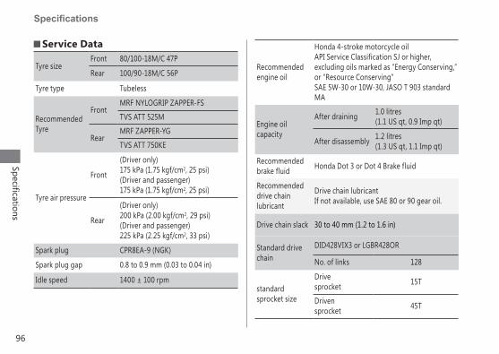
96
Specifications
Specifications
J Service Data
Tyre sizeFront 80/100-18M/C 47P
Rear 100/90-18M/C 56P
Tyre type Tubeless
Recommended Tyre
FrontMRF NYLOGRIP ZAPPER-FS
TVS ATT 525M
RearMRF ZAPPER-YG
TVS ATT 750KE
Tyre air pressure
Front
(Driver only)175 kPa (1.75 kgf/cm2, 25 psi)(Driver and passenger)175 kPa (1.75 kgf/cm2, 25 psi)
Rear
(Driver only)200 kPa (2.00 kgf/cm2, 29 psi)(Driver and passenger)225 kPa (2.25 kgf/cm2, 33 psi)
Spark plug CPR8EA-9 (NGK)
Spark plug gap 0.8 to 0.9 mm (0.03 to 0.04 in)
Idle speed 1400 ± 100 rpm
Recommended engine oil
Honda 4-stroke motorcycle oilAPI Service Classification SJ or higher, excluding oils marked as “Energy Conserving,” or “Resource Conserving” SAE 5W-30 or 10W-30, JASO T 903 standard MA
Engine oil capacity
After draining 1.0 litres (1.1 US qt, 0.9 Imp qt)
After disassembly 1.2 litres (1.3 US qt, 1.1 Imp qt)
Recommended brake fluid Honda Dot 3 or Dot 4 Brake fluid
Recommended drive chain lubricant
Drive chain lubricantIf not available, use SAE 80 or 90 gear oil.
Drive chain slack 30 to 40 mm (1.2 to 1.6 in)
Standard drive chain
DID428VIX3 or LGBR428OR
No. of links 128
standard sprocket size
Drivesprocket 15T
Drivensprocket 45T

97
SpecificationsSpecifications
J FusesMain fuse 20 A x 1
Other fuses 7.5 A x 310 A x 2
J Torque SpecificationsEngine oil drain bolt 30 N·m (3.1 kgf·m, 22 lbf·ft)
Rear axle nut 88 N·m (9.0 kgf·m, 65 lbf·ft)
Front axle nut 59 N·m (6.0 kgf·m, 44 lbf·ft)
JBulbsHeadlight 12 V-35/35 W
Brakelight/Taillight 12 V-21 / 5 W
Front turn signal 12 V- 10 W x 2
Rear turn signal 12 V- 10 W x 2
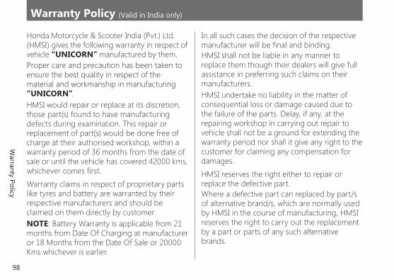
98
Warranty Policy
Warranty Policy (Valid in India only)
Honda Motorcycle & Scooter India (Pvt.) Ltd. (HMSI) gives the following warranty in respect of vehicle “UNICORN” manufactured by them.Proper care and precaution has been taken to ensure the best quality in respect of the material and workmanship in manufacturing “UNICORN”.HMSI would repair or replace at its discretion, those part(s) found to have manufacturing defects during examination. This repair or replacement of part(s) would be done free of charge at their authorised workshop, within a warranty period of 36 months from the date of sale or until the vehicle has covered 42000 kms, whichever comes first.
Warranty claims in respect of proprietary parts like tyres and battery are warranted by their respective manufacturers and should be claimed on them directly by customer.NOTE: Battery Warranty is applicable from 21 months from Date Of Charging at manufacturer or 18 Months from the Date Of Sale or 20000 Kms whichever is earlier.
In all such cases the decision of the respective manufacturer will be final and binding.HMSI shall not be liable in any manner to replace them though their dealers will give full assistance in preferring such claims on their manufacturers.HMSI undertake no liability in the matter of consequential loss or damage caused due to the failure of the parts. Delay, if any, at the repairing workshop in carrying out repair to vehicle shall not be a ground for extending the warranty period nor shall it give any right to the customer for claiming any compensation for damages.
HMSI reserves the right either to repair or replace the defective part.Where a defective part can replaced by part/s of alternative brand/s, which are normally used by HMSI in the course of manufacturing, HMSI reserves the right to carry out the replacement by a part or parts of any such alternative brands.
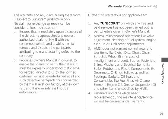
99
Warranty Policy
Warranty Policy (Valid in India only) Warranty Policy (Valid in India Only)
This warranty and any claim arising there from is subject to Gurugram jurisdiction only.No claim for exchange or repair can be consider unless the customer:a. Ensures that immediately upon discovery of
the defect, he approaches any nearest authorised dealer of HMSI with the concerned vehicle and enables him to remove and dispatch the part/parts attributing to manufacturing defect to the company.
b. Produces Owner’s Manual in original, to enable that dealer to verify the details. It must be expressly understood that claims forwarded directly to us by the owner/customer will not be entertained at all and such defective part/parts thus forwarded by them will lie at our factory at their own risk, and this warranty shall not be enforceable.
Further this warranty is not applicable to:
1. Any “UNICORN” on which any free and paid services has not been carried out, as per schedule given in Owner’s Manual.
2. Normal maintenance operations like valve adjustment, cleaning of fuel system, engine tune-up or such other adjustments.
3. HMSI does not warrant normal wear and tear items like Clutch Disc, Chain, Chain Sprocket, Wheel Rim (in case of misalignment and bent), Bushes, Fasteners, Shims, Washers and Electrical Items like Bulbs, Rubber and Plastic Components like Grommets, O-Rings,Bellows as well as Packings, Gaskets, Oil Seals and Consumables like Fuel Filter, Air Cleaner Element, Engine Oil, Grease, Suspension Oil and other items as specified by HMSI.
4. Fasteners and clips which needs replacement during maintenance/service will not be covered under warranty.

100
Warranty Policy
Warranty Policy (Valid in India only)Warranty Policy (Valid in India Only)
5. If there is any damage to the painted surface due to industrial pollution or other extraneous factors.
6. Any damage resulting from unavoidable natural disaster i.e fire collision, earthquake, flood etc.
7. Any damage caused by exposure of the product to soot and smoke, chemical agents, bird-droppings, sea water, sea breeze, or other environmental phenomenon.
8. If there is any damage caused due to usage of improper oil/grease, non genuine parts.
9. For two-wheelers, which have been used for any commercial purposes as taxi etc.
10. For maintenance repairs required due to misuse while driving or due to adulteration of oil, petrol or due to bad road conditions.
11. Recommended fuel quality not used.12. Parts of the vehicle that have been
subjected to misuse, accident, negligent treatment or which have been used in conjunction with parts and an equipment
not manufactured or recommended for use by HMSI if in the sole judgment of HMSI, such use prematurely affects the performance and reliability of the vehicle.
13. Parts of the vehicle that have been altered or modified or replaced in unauthorised manner, and which in the sole judgment of HMSI affect its performance and reliability.
14. The vehicle that has not been serviced by HMSI authorised dealer as per the service schedule or which have not been operated or maintained in accordance with instructions mentioned in the Owner’s Manual.
15. The vehicles used for any competition or race and/or for attempting to set up any kind of record HMSI reserves the right to make any changes in design or to add any improvement on the vehicle at any time without incurring any obligations to install the same on a vehicle previously supplied and sold. Also the conditions of this warranty are subject to alteration without any notice.
101
Warranty Policy
Warranty Policy (Valid in India only) Warranty Policy (Valid in India Only)
This warranty is entirely written warranty given by HMSI for “UNICORN” and no other person, including the dealer or its or his agent or employee is authorised to extend or enlarge this warranty.
This warranty is given in lieu of and excludes every condition or warranty whether statutory or otherwise not herein expressly set out.
EMISSION WARRANTYSubject to other terms of the warranty policy and other conditions and obligations laid down hereunder, the manufacturer certifies that the components liable to affect the emission of the gaseous pollutants in the vehicle in normal use despite the use to which it may be subjected, comply with provisions of rule 115(2) of the Central Motor Vehicle Rules, 1989 and further warrants that if on examination by a service center duly authorized by the manufacturer, the vehicle is discovered to be failing to meet the emission standard as specified in the said rule,
the authorized service center shall take such corrective measures as may be necessary and shall at its sole discretion replace free of charge such components of emission control system as are specified in schedule.
A. Conditions1. This warranty will be in addition to and run
parallel to the product warranty given by the manufacturer and will apply to components as mentioned later. This warranty is applicable in Delhi, Mumbai, Kolkata and Chennai with effective from 1st July 2001. Other places when included will be covered under warranty accordingly.
2. The period of the vehicle’s emission warranty will be determined starting from the date of the vehicle sale. The period of time and kilometers that are covered under the provisions of warranty may vary but should not be less than the minimum warranty period based on the vehicle category.
For a two-wheeler the emission warranty period is 30,000 kms or 3 years whichever is earlier.
102
Warranty Policy
Warranty Policy (Valid in India only)Warranty Policy (Valid in India Only)
3. Warranty claim for the components under Emission warranty will be admitted, for a prima facie examination, in the event of failure of the vehicle to meet the emission standard as specified in sub-rule (2) of Rule No 115 of the Central Motor vehicle Rules.
4. The warranty claim will be accepted only after the examinations carried out by Authorized Service Centers leads to a firm conclusion that none of the original settings have been tampered with and that the components has/have a manufacturing defect, and/or, that the vehicle is unable to meet the in-use emission standard, in spite of the vehicle being maintained and used in accordance with the instructions in the owner’s manual.
5. The methods of examination to determine the warrantable condition of the components will be at the sole discretion of manufacturers and or their Authorized service centers and results
of such examination will be final and binding. If, on examination, a warrantable condition is not established, the manufacturers will have to charge all, or part, of the cost of such examination.
6. In case of a vehicle in which the components covered under Emission warranty, the manufacturer will replace, at Authorized centers free of charge, the components which are covered, but the consumables as mentioned in Owner’s Manual shall be charged as per actuals.
7. In case of a vehicle in which the components covered under Emission warranty or the associated parts are not independently replaceable on account of their being integral parts of a complete assembly, the manufacturer will have the sole discretion to replace either the entire assembly or by using some of the parts of the system through suitable repairs or modifications.
103
Warranty Policy
Warranty Policy (Valid in India only) Warranty Policy (Valid in India Only)
8. Any consequential repairs or replacement of parts which may be found necessary to establish compliance to in-use emission standards, in addition to replacement of the parts covered under emission warranty, will not be made free of cost unless such parts are also found to be in a warrantable condition within the scope and limit of the product warranty. The consumables shall be charged as per actual during such repairs or replacement of parts.
9. All the parts removed for replacement under warranty will be the property of the manufacturer.
10 The manufacturer will not be responsible for the cost of transportation of the vehicle to the nearest Authorized Service center or any loss due to non-availability of the vehicle during the period of lodging of a warranty claim and examination by the manufacturer and repairs.
11. The manufacturer will not be responsible for any penalties that may be charged by
statutory authorities on account of failure to comply with the in use emission standards.
12. Emission warranty will be applicable irrespective of the change of ownership of the vehicle provided all the conditions as laid down in this document are met from the date of original sale of the vehicle.
13. The emission warranty will be applicable only if: a. Observes all the important instructions
and any other precautions listed in the Owner’s Manual for use of the vehicle.
b. Under all circumstances uses lubricants and fuel as recommended by manufacturer.
c. Regularly obtains and carries out maintenance in accordance with the manufacturers guidelines and enters the details in the Logbook.
d. Immediately approaches the nearest authorized service center upon discovery of failure to comply with the
104
Warranty Policy
Warranty Policy (Valid in India only)Warranty Policy (Valid in India Only)
in use emission standards in spite of having maintained and used the vehicle in accordance with the instructions in the Owner’s Manual and having carried out such repairs and adjustments as may be required with a view to establish such compliance.
e. Produces the ‘Pollution Under Control’ certificate valid for the period immediately preceding the test during which the failure is discovered, the test having been carried out either for obtaining a new certificate, or pursuant upon being directed by an officer as referred to in sub-rule(2) of Rule 116 of the Central Motor Vehicle Rules.
f. Produces the Owner’s Manual and Log book for verification details.
g. Produces receipts covering maintenance of the vehicle as specified in the Owner’s Manual from the date of original purchase of the vehicle.
h. Produces valid certificate of insurance and RTO registration.
14. Conditions under which warranty is not applicable:
A valid ‘Pollution Under Control’ certificate as described in customer obligation D(6) above is not produced.
A vehicle which is not serviced by Authorized service center as per the service schedule described in the maintenance chart given in the Owner’s Manual.
A vehicle, which has been subjected to abnormal use, abuse, neglect and improper maintenance or has met with an accident. Use of replacement parts not specified and approved by the manufacturer.
A vehicle, or parts thereof, which has been altered, tampered with or modified or replaced in an unauthorized manner.
A vehicle on which the odometer is not functioning or the odometer has been changed/tampered with so that the actual mileage cannot be readily determined.

105
Warranty Policy
Warranty Policy (Valid in India only) Warranty Policy (Valid in India Only)
A vehicle which has been used for competitions, races, rallies or for the purpose of establishing records.
Examination by the manufacturers or his Authorized Service Centers of the vehicle shows that any of the conditions stipulated in the Owner’s Manual with regard to use and maintenance have been violated.
A vehicle, which has been run on, adulterated fuel, leaded fuel or lubricant or fuel/lubricants other than those specified by the manufacturer in the Owner’s Manual with regard to use and maintenance have been violated.
SCOPE AND LIMITS1. This emission warranty is in addition to product
warranty and shall run parallel to the product warranty for the vehicle as per the scope and limit described in the Owner’s Manual and all conditions described there in will apply in addition to those exclusively stipulated in this warranty.
2. The emission warranty covers only compliance with the emission standard as specified in the sub rule (2) of rule 115 of CMVR. It does not cover any other performance of these parts or routine test and consequent maintenance or adjustments to establish compliance to the in use emission standard as applicable to the state, in which the vehicle is registered and is in use.
The parts, which are covered under emission warranty, are carburetor and internal parts, intake manifold, distributor and internal parts, ignition coil, muffler etc.NOTE: The emission warranty is applicable only when a customer enters into emission warranty contract.

106
Index
Index
AABS (Anti-lock Brake System) on Front Wheel ....................................................................... 9
ABS (Anti-lock Brake System) Indicator ..........................................................17, 71
Accessories ............................................................12BBattery .............................................................. 33, 43Brakes
Brake Pedal Freeplay ......................................... 55Brake Light Switch ..............................................58Fluid ....................................................................... 53Pad Wear ..............................................................54Shoe Wear ............................................................57
Braking ....................................................................... 9Bulb
Brake/Tail Light ...................................................79Front Turn Signal ................................................79Headlight ..............................................................78Rear Turn Signal ..................................................79
CCaring for Your Vehicle ....................................86Clutch ......................................................................63
Catalytic Converter ...........................................94Compartment
Document Bag ............................................. 25, 85Owner’s Manual .................................................85Tool Kit ..................................................................25
Crankcase Breather............................................66EElectrical Trouble .................................................77Engine
Number................................................................. 92Oil .............................................................36, 50, 96Starting .................................................................20
Environment .......................................................... 91FFrame Number .....................................................92Fuel
Gauge .................................................................... 16Recommended ................................................... 24Remaining ............................................................ 16Tank Capacity ...................................................... 24
Fuels Containing Alcohol ................................ 93Fuses .................................................................. 35, 97
107
Index
GGasohol ................................................................... 93
HHeadlight Aim ......................................................67Headlight Case ..................................................... 45Headlight Dimmer Switch...............................18Helmet Holder .....................................................26High Beam Indicator ......................................... 17Horn Button .......................................................... 18
IIgnition Key ...........................................................84Ignition Switch .............................................. 19, 85Image Labels .......................................................... 6Indicators................................................................ 17Instruments ........................................................... 16
KKeys ...........................................................................84
LLabels ......................................................................... 6Load Limits ............................................................13Loading Guidelines ............................................13
MMaintenance
Fundamentals ...................................................... 32Importance ..........................................................28Safety .....................................................................28Schedule ...............................................................29
Maximum Weight Limit ............................ 13, 95Modifications ........................................................12NNeutral Indicator ................................................. 17
OOdometer ....................................................... 16, 85Oil
Engine .....................................................36, 50, 96
PParking ..................................................................... 10Parts Location ...................................................... 14Passing Light Control Switch .........................18Petrol ................................................................. 24, 93PGM-FI (Programmed Fuel Injection) Malfunction Indicator Lamp (MIL) ..........17, 71
Protective Apparel ............................................... 8
108
Index
RRecommended
Fuel......................................................................... 24Oil ...........................................................................36
Refueling ................................................................. 24Removal
Battery ................................................................... 43Drive Chain Case ................................................44Headlight Case .................................................... 45Seat ........................................................................46Side Cover ............................................................ 47
Riding Precautions ............................................... 9
SSafety Precautions ............................................... 8Seat ...........................................................................46Serial Numbers ....................................................92Side Stand .............................................................. 59Spark Plug ..............................................................48Specifications .......................................................95Speedometer ....................................................... 16Start Button .......................................................... 18Starting the Engine ............................................20Steering Lock ........................................................19
Storage Equipment ............................................25Storing Your Vehicle ..........................................89Switches ..................................................................18
TThrottle.................................................................... 65Tool ........................................................................... 42Transporting Your Vehicle ..............................90Tripmeter ......................................................... 16, 85Troubleshooting ..................................................69Turn signal indicators ........................................ 17Tyres
Air Pressure ................................................... 39, 96Puncture ...............................................................72Replacing ....................................................... 39, 72
WWarning Indicator On or Flashing ..............71Warranty Policy ...................................................98Washing Your Vehicle .......................................86Weight Limit..........................................................13Wheels
Front Removal .....................................................73Rear Removal ......................................................75