Permanent joints (Assemblages permanents ) _Course - ISET ...
79
Higher Institute of Technological Studies of Gafsa-Tunisia Department of Mechanical Engineering Applied License in Mechanical Engineering Metallic Construction Integrated course: Permanent joints Prepared by: Rached Nciri Technologist, Doctor Engineer Level 2- Applied license in Mechanical Engineering-Metallic Construction Academic year: 2020-2021
-
Upload
khangminh22 -
Category
Documents
-
view
0 -
download
0
Transcript of Permanent joints (Assemblages permanents ) _Course - ISET ...

Higher Institute of Technological Studies of Gafsa-Tunisia
Department of Mechanical Engineering
Applied License in Mechanical Engineering
Metallic Construction
Integrated course: Permanent joints
Prepared by: Rached Nciri Technologist, Doctor Engineer
Level 2- Applied license in Mechanical Engineering-Metallic Construction
Academic year: 2020-2021

Foreword
The content of this material consists of a course entitled “Permanent
joints”. It is addressed to the students preparing the Applied License in
Mechanical Engineering-Metallic Construction, taught in the Department of
Mechanical Engineering of the Higher Institute of Technological Studies of
Gafsa-Tunisia. More globally, all students who receive a technological
education in Mechanical Engineering can benefit from this material. This is a
first version that can be improved and updated whenever required.

PERMANENT JOINTS
COURSE
• Domain : Mechanical Engineering-Metallic Construction
• Level : L2-CME2-S32
• Prerequisites: Level 1-Applied License in Mechanical
Engineering.
• Number of hours: 21 hours.
• Goals :
- To know the main technical details of the conventional
welding processes (SMAW, GMAW and GTAW).
- To know the main technical details of the liquid state welding
processes (High energy welding, Resistance welding and
Laser-hybrid welding).
- To know the main technical details of the solid state welding
processes (Friction welding, Ultrasonic welding, Diffusion
welding, Explosion welding).
- To master the welding symbols (based on the AWS
standards).
- To master the design resistance/sizing of fillet welds (based
on the Eurocode 3 standards).
- To know the main technical details of the principal types of
permanent joints other than welding.

Table of contents
CHAPTER 1. CONVENTIONAL WELDING PROCESSES. ....................................... 4
1. Shielded Metal Arc Welding (SMAW) .......................................................................... 4
1.1. Principle of the SMAW .............................................................................................. 4
1.2. Types of welding position and joint............................................................................ 5
1.3. Coated electrode.......................................................................................................... 6
1.4. Types of coating .......................................................................................................... 7
1.5. Parameters and aspects of the SMAW ........................................................................ 8
2. Gas Metal Arc Welding (GMAW) ............................................................................... 10
2.1. Principle of the GMAW ............................................................................................ 10
2.2. Parameters of the GMAW ........................................................................................ 11
3. GMAW modes of metal transfer .................................................................................. 13
4. Gas Tungsten Arc Welding (GTAW) .......................................................................... 14
4.1. Principle of the GTAW ............................................................................................. 14
4.2. GTAW current .......................................................................................................... 15
4.3. GTAW electrode ....................................................................................................... 16
4.4. GTAW nozzle ........................................................................................................... 16
4.5. Parameters of the GTAW.......................................................................................... 17
5. Safety instructions ......................................................................................................... 19
6. References ....................................................................................................................... 19
CHAPTER 2. LIQUID STATE WELDING PROCESSES. .......................................... 22
1. High energy welding ...................................................................................................... 22
1.1. Plasma Arc Welding (PAW) ..................................................................................... 22
1.1.1. Principle of Plasma Arc Welding ....................................................................... 22
1.1.2. Types of Plasma Arc Welding ........................................................................... 22
1.1.3. Advantages/Limitations of Plasma Arc Welding ............................................... 25
1.2. Electron Beam Welding (EBW) ............................................................................... 25

1.2.1. Principle of Electron Beam Welding ................................................................. 25
1.2.2. Advantages/Limitations of electron beam welding ............................................ 25
1.3. Laser beam welding (LBW)...................................................................................... 26
1.3.1. Principle of Laser Beam Welding ...................................................................... 26
1.3.2. Advantages/Limitations of Laser Beam Welding .............................................. 27
2. Resistance Welding ........................................................................................................ 28
2.1. Spot welding ............................................................................................................. 28
2.1.1. Principle of spot welding.................................................................................... 28
2.1.2. Advantages/Limitations of spot welding ........................................................... 28
2.2. Projection welding .................................................................................................... 30
2.2.1. Principle of projection welding .......................................................................... 30
2.2.2. Advantages/Limitations of projection welding .................................................. 31
2.3. Seam welding ............................................................................................................ 32
2.3.1. Principle of seam welding .................................................................................. 32
2.3.2. Advantages/Limitations of seam welding .......................................................... 32
2.4. Butt welding .............................................................................................................. 33
2.4.1. Principle of butt welding .................................................................................... 33
2.4.2. Advantages/Limitations of butt welding ............................................................ 33
3. Laser-hybrid welding .................................................................................................... 34
3.1. Principle of Laser-hybrid welding ............................................................................ 34
3.1.1. Advantages/Limitations of Laser-hybrid welding ............................................. 34
4. References ....................................................................................................................... 36
CHAPTER 3. SOLID STATE WELDING PROCESSES. ............................................ 37
1. Friction Welding (FRW) process ................................................................................. 37
1.1. Principle of the Friction Welding (FRW) process .................................................... 37
1.2. Advantages/Limitations of the Friction Welding (FRW) process ............................ 37
2. Ultrasonic Welding (USW) process.............................................................................. 40
2.1. Principle of the Ultrasonic Welding (USW) process ................................................ 40
2.2. Advantages/Limitations of the Ultrasonic Welding (USW) process ........................ 41

3. Diffusion Welding (DW) ............................................................................................... 41
3.1. Principle of the Diffusion Welding (DW) process ................................................... 41
3.2. Advantages/Limitations of the Diffusion Welding (DW) process ........................... 42
4. Explosion Welding (EXW) ............................................................................................ 43
4.1. Principle of the Explosion Welding (EXW) process ................................................ 43
4.2. Advantages/Limitations of the Explosion Welding (EXW) process ........................ 44
5. References ....................................................................................................................... 44
CHAPTER 4. WELDING SYMBOLS. ........................................................................... 46
1. Welds types ..................................................................................................................... 46
1.1. Fillet weld ................................................................................................................. 46
1.2. Groove weld .............................................................................................................. 46
1.3. Surfacing weld .......................................................................................................... 47
1.4. Plug weld .................................................................................................................. 47
1.5. Slot weld ................................................................................................................... 48
1.6. Flash weld ................................................................................................................. 48
1.7. Seam weld ................................................................................................................. 49
1.8. Spot weld .................................................................................................................. 49
1.9. Upset weld ................................................................................................................ 49
2. Welding symbols chart .................................................................................................. 50
3. Basic welding symbol examples .................................................................................... 51
3.1. Welding symbol for fillet welds ............................................................................... 51
3.1.1. Location .............................................................................................................. 51
3.1.2. Size ..................................................................................................................... 51
3.1.3. Pitch .................................................................................................................... 52
3.1.4. All around ........................................................................................................... 52
3.2. Groove welds ............................................................................................................ 53
3.2.1. Types .................................................................................................................. 53
3.2.2. Size ..................................................................................................................... 54
4. Specific welding symbol examples................................................................................ 54

4.1. Back and backing welds............................................................................................ 54
4.2. Weld contours and finishing of welds ...................................................................... 55
5. References ....................................................................................................................... 56
CHAPTER 5. RESISTANCE/SIZING OF WELD BEADS .......................................... 57
1. Weld constituent elements ............................................................................................ 57
1.1. Effective throat thickness .......................................................................................... 57
1.2. Useful length ............................................................................................................. 57
1.3. Effective area ............................................................................................................ 58
2. Principal types of loads ................................................................................................. 58
2.1. Weld subjected to tensile .......................................................................................... 59
2.2. Weld subjected to pure shear .................................................................................... 59
2.3. Weld subjected to tensile and shear .......................................................................... 59
3. Stresses within welds ..................................................................................................... 60
4. Practical exercises .......................................................................................................... 62
4.1. Directional method for design resistance of fillet weld/Weld sizing ........................ 62
4.1.1. Weld subjected to pure shear ............................................................................. 62
4.1.2. Weld subjected to tensile and shear ................................................................... 64
4.2. Simplified method for design resistance of fillet weld ............................................. 66
5. References ....................................................................................................................... 67
CHAPTER 6. OTHER TYPES OF PERMANENT JOINTS........................................ 68
1. Brazing process .............................................................................................................. 68
1.1. Principle of the brazing process ................................................................................ 68
1.2. Industrial applications of the brazing process ........................................................... 70
2. Riveting process ............................................................................................................. 71
2.1. Principle of the riveting process ............................................................................... 71
2.2. Industrial applications of the riveting process .......................................................... 73
3. Mechanical crimping process ....................................................................................... 73

3.1. Principle of the crimping process ............................................................................. 73
3.2. Industrial applications of the crimping process ........................................................ 73
4. References ....................................................................................................................... 74

Higher Institute of Technological Studies_Gafsa-Tunisia Permanent joints Department of Mechanical Engineering Conventional welding processes
4 Rached Nciri, D. Eng., Technologist
Chapter 1. Conventional welding processes.
In order to carry out permanent joints in weldments, a technological variety of
conventional welding processes is provided. Among this welding variety, the most used types
of welding are:
• Shielded Metal Arc Welding (SMAW).
• Gas Metal Arc Welding (GMAW).
• Gas Tungsten Arc Welding (GTAW).
1. Shielded Metal Arc Welding (SMAW)
1.1. Principle of the SMAW
The principle of the SMAW [1.1,1.2] (and all arc welding processes) is based on the
production of heat from electrical energy by the Joule effect. The produced heat is used to
fuse the edges of the workpieces to be joined. The arc welding power source produces a high
electrical current (AC or DC current) that will pass through both electrode (connected to one
terminal of the power source) and workpiece (connected to the other terminal of the power
source). Electric cables, electrode holder and workpiece connector (clamp) are used to ensure
the electrical circuit. When the electrode is close enough to the workpiece (almost 2 mm to 3
mm), the high electrical current will be able to pass through the air gap between the electrode
and the workpiece. The air, initially considered as a highly insulating medium, becomes
conductor under the influence of the high electrical current: an electric arc is created. This
electric arc is simply the revelation of the passage of electric current through the air. The air
crossed by the electric current releases heat thanks to the Joule effect. Hence, the fusion of the
workpiece (base metal) edges and the coated electrode (filler metal) is created: the weld bead
is created. Figure 1.1 [1.3] depicts the different components of a SMAW machine. Figure 1.2
[1.4] depicts the SMAW welding phenomena.

Higher Institute of Technological Studies_Gafsa-Tunisia Permanent joints Department of Mechanical Engineering Conventional welding processes
5 Rached Nciri, D. Eng., Technologist
Figure 1.1. Components of a SMAW machine.
Figure 1.2. SMAW welding phenomena.
1.2. Types of welding position and joint
Figure 1.3 [1.7] depicts the different welding positions and joints.

Higher Institute of Technological Studies_Gafsa-Tunisia Permanent joints Department of Mechanical Engineering Conventional welding processes
6 Rached Nciri, D. Eng., Technologist
Figure 1.3. Welding positions and joints.
1.3. Coated electrode
The SMAW coated electrode consists of 2 parts as depicted by Figure 1.4.
Figure 1.4. SMAW coated electrode.
• Electrode: it is a metallic rod intended to conduct the electric current. It is generally of
the same nature as that of the workpiece.

Higher Institute of Technological Studies_Gafsa-Tunisia Permanent joints Department of Mechanical Engineering Conventional welding processes
7 Rached Nciri, D. Eng., Technologist
• Coating: it is an adhesive chemical composition that covers the electrode, and it is
intended to play 3 principal roles [1.2]:
o Metallurgical roles: protection of the molten weld pool against Oxygen and
Nitrogen form the ambient air, harmful to the mechanical properties of the
weld bead. This protection is ensured by producing a protective layer, called a
slag, which will envelop the molten weld bead.
o Electrical roles: facilitating the strike (ignition) of the electric arc and maintain
its stability.
o Mechanical roles:
- Channeling and concentration of the electric arc.
- Improvement of the mechanical properties of the weld bead.
1.4. Types of coating
Table 1.1 summarizes the most used types of coating [1.5,1.6] as well as their chemical
characteristics, welding applications and eventual precautions to consider.
Table 1.1. Coating typology and applications.
Type of
coating
Chemical
characteristics Welding applications Precautions
Basic (B) High proportion of calcium carbonate and fluoride
- Limestone slag (desulfurizing effect) -Suitable for welding ferritic steels - Reduced risk of hot cracking of the deposited metal - Direct current / reverse polarity (electrode at terminal +)
Steaming at 350 ° for 2 hours. (unless otherwise specified by the supplier)
Cellulosic (C)
High proportion of cellulose
- Little slag -Suitable for rapid welding in downward position - Improved penetration - Direct current / reverse polarity (electrode at terminal +)
Open circuit voltage ≥60V
Rutile (R) High proportion of titanium dioxide
- Slag is easily eliminated -Suitable for welding in all positions -Metal deposited with good
No special precautions

Higher Institute of Technological Studies_Gafsa-Tunisia Permanent joints Department of Mechanical Engineering Conventional welding processes
8 Rached Nciri, D. Eng., Technologist
mechanical characteristics when steels have limited carbon and sulfur contents - Direct / alternating current
Acid (A) High proportion of acidic matter
- Very fluid and abundant slag - Suitable for flat, horizontal (Corner joint and T-joint) welding. Not suitable for vertical (Up and down) and overhead welding. - Requires good weldability of the base metal otherwise joint sensitive to hot cracking.
No special precautions
1.5. Parameters and aspects of the SMAW
There are several parameters for SMAW:
• Diameter of the electrode.
The appropriate diameter of the electrode eφ is determined according to the
thickness t of the workpiece [1.8]. Comply with the indications on the supplier's
technical data sheets or use the Formula 1.1.
te
≤φ (1.1)
• Intensity of the electrical current.
The intensity of the welding current I depends mainly on the diameter of the
electrodee
φ [1.1,1.8]. Comply with the indications on the supplier's technical data
sheets or use the Formula 1.2 for butt joint:
)(I)mm(
e
)A(
150 −×= φ (1.2)
For corner joint, the value of the current intensity is reduced by 20%.
For T-joint, the value of the current is increased by 20%.
• Travel speed (speed of the movement of the electrode during the welding operation).
• Distance between the electrode and the workpiece (air gap dimension).

Higher Institute of Technological Studies_Gafsa-Tunisia Permanent joints Department of Mechanical Engineering Conventional welding processes
9 Rached Nciri, D. Eng., Technologist
• Welding positions (flat, horizontal (Corner joint and T-joint) and vertical: up and
down).
• Welding polarity.
When the Direct Current (DC) is used, the SMAW welding polarity may be 2 types [1.9]:
o Straight polarity: it is a direct current with a negatively charged electrode and
a positively charged workpiece (DCEN). With a straight polarity, 2/3rd of the
arc heat is generated near the workpiece while the remaining 1/3rd is generated
at the electrode tip. The melting rate of the workpiece increases and the filler
deposition rate of the electrode decreases. The width of the weld bead is
decreased while the penetration (depth) is increased.
o Reverse polarity: it is a direct current with a positively charged electrode and a
negatively charged workpiece (DCEP). With a reverse polarity, 2/3rd of the arc
heat is generated at the electrode tip while the remaining 1/3rd is generated
near the workpiece. The melting rate of the electrode increases and the filler
deposition rate of the electrode increases. The width of the weld bead is
increased while the penetration is decreased.
It is to note that when the alternating current is used, the polarity will change almost 100
times per second. An even heat distribution is created, so, between the electrode and the
workpiece. Thus, a balance between bead penetration and electrode filler deposition rate
(bead width) is provided.
The variation of these parameters mainly affects the following welding aspects:
• Size and shape of the weld bead.
• Penetration of the filler metal within the base metal.
• Fusibility of the coated electrode.
The principal weld bead aspects are depicted by the Figure 1.5.

Higher Institute of Technological Studies_Gafsa-Tunisia Permanent joints Department of Mechanical Engineering Conventional welding processes
10 Rached Nciri, D. Eng., Technologist
Figure 1.5. Weld bead aspects.
2. Gas Metal Arc Welding (GMAW)
2.1. Principle of the GMAW
The GMAW process, also called MIG/MAG (Metal Inert Gas/Metal Active Gas), is part of
the arc welding family. It consists in establishing, under gaseous protection injected
continuously (against Oxygen and Nitrogen in the air), an electric arc between the tip of an
electrode (generally bare copper conductive wire, unwinding at a predetermined speed) and
the workpiece. When the shielding gas does not react with the molten weld bead, it is called
inert. Argon and the mixture between Argon and Helium are neutral gases. When the
shielding gas does not react with the molten weld bead, it is qualified by active. The mixture
between carbon dioxide, hydrogen and argon (in varying proportions depending on the nature
of the metal to be welded) are active gases. Figure 1.6 [1.10] depicts the principal components
of a GMAW machine. Figure 1.7 depicts the components of a typical GMAW torch (gun)
[1.11]. Figure 1.8 [1.10] depicts the GMAW welding phenomena.
Figure 1.6. Principal components of a GMAW machine.

Higher Institute of Technological Studies_Gafsa-Tunisia Permanent joints Department of Mechanical Engineering Conventional welding processes
11 Rached Nciri, D. Eng., Technologist
Figure 1.7. GMAW torch (gun).
Figure 1.8. GMAW welding phenomena.
2.2. Parameters of the GMAW
The GMAW parameters [1.12] are the quantities which influence the aspects of GMAW
weld bead: size and shape as well as the penetration of the weld bead into the base metal. The
GMAW parameters are mainly:
• Voltage
• Wire feed speed (the intensity of the welding current is proportional to the wire feed
speed)
• Wire diameter
• Distance between torch and workpiece
• Torch movement speed
• Torch position

Higher Institute of Technological Studies_Gafsa-Tunisia Permanent joints Department of Mechanical Engineering Conventional welding processes
12 Rached Nciri, D. Eng., Technologist
The manufacturer of the GMAW machine generally provides the GMAW parameters
depending on the thickness of the part to be welded (Table 1.2) [1.13].
Table 1.2. GMAW parameters for a SAFMIG 400 BL welding machine. T
hic
kn
ess
(mm
)
Po
siti
on
Wir
e d
iam
eter
(mm
)
Volt
age
(V)
Wir
e fe
ed s
pee
d
(m/m
in)
Cu
rren
t
Inte
nsi
ty (
A)
Sw
itch
po
siti
on
Ma
teri
al
Gas
Wir
e m
ate
rial
10/10 30/10
Fillet
0.8 16 19
2.8 7.8
55 125
A-1 C-2
Ste
el
AT
AL
7
0S
15/10
Butt
0.8 17.5 5.4 90 B-2
15/10 30/10 80/10
Fillet
1 16 18 28
3.1 5.5
10.5
90 135 190
A-1 B-4 E-3
15/10
Butt
1 16 3 80 A-2
15/10 30/10 80/10
Fillet
1.2 14.5 17 29
3 3.8 8.5
140 180 275
A-1 B-1 E-1
20/10
Butt
1.2 15 2.8 115 A-2
40/10 80/10
Fillet
1.2 16 27
3.7 7.8
110 220
A-4 E-2 S
teel
A
TA
L
SD
20
0
30/10
Butt
1 16 11.3 105 A-4
A-L
A
rgo
n
Ner
tali
c 3
0
20/10 30/10 60/10
Fillet
1 15 16 26
9.6 13
21.5
100 130 210
A-1 A-4 D-2

Higher Institute of Technological Studies_Gafsa-Tunisia Permanent joints Department of Mechanical Engineering Conventional welding processes
13 Rached Nciri, D. Eng., Technologist
Th
ick
nes
s (m
m)
Po
siti
on
Wir
e d
iam
eter
(mm
)
Volt
age
(V)
Wir
e fe
ed s
pee
d
(m/m
in)
Cu
rren
t
Inte
nsi
ty (
A)
Sw
itch
po
siti
on
Ma
teri
al
Gas
Wir
e m
ate
rial
30/10
Butt
1.2 16 8.9 130 A-3
A-L
A
rgo
n
Ner
tali
c 3
0
20/10 60/10
Fillet
1.2 15 27
7.4 16.5
110 275
A-1 D-4
30/10 80/10
Butt
1.6 15 27
5.2 10
130 260
A-2 D-4
10/10 15/10 50/10 80/10
Fillet
1
15.5 16 21 25
2.6 3
9.3 9.7
60 72
165 180
A-1 A-1 C-4 C-4
Sta
inle
ss s
teel
N
ox
alic
12
N
erta
lic
50
20/10
Butt
1 17 5.1 100 B-1
15/10 30/10 50/10 80/10
Fillet
1.2
16 17 20 29
2.7 4.3 7.5
10.5
80 140 200 245
A-1 B-2 C-4 E-4
15/10
Butt
1.2 16 2.6 75 A-1
30/10 80/10
Fillet
1.6 16
25.5 2.5 3.1
165 240
B-2 D-2
3. GMAW modes of metal transfer
Table 1.3 summarizes the principal GMAW modes of metal transfer and their
technological attributes (current intensity, workpiece thickness and welding position) [1.14].

Higher Institute of Technological Studies_Gafsa-Tunisia Permanent joints Department of Mechanical Engineering Conventional welding processes
14 Rached Nciri, D. Eng., Technologist
Table 1.3. Principal modes of metal transfer and their attributes for GMAW.
Metal transfer
modes
Current
intensity
Thickness of
workpiece Position
Short-circuit transfer 30A-200A Thin workpiece Any position (Flat,
Horizontal, Vertical and Overhead) Axial spray transfer 200A-400A Thick workpiece Flat and horizonal
4. Gas Tungsten Arc Welding (GTAW)
4.1. Principle of the GTAW
The GTAW process, also called TIG (Tungsten Inert Gas), is part of the arc welding
family. It consists in establishing, under gaseous protection injected continuously (against
Oxygen and Nitrogen in the air), an electric arc between the tip of a non-fusible Tungsten
electrode and the workpiece. Argon and the mixture of Argon and Helium are the neutral
gases used in TIG welding. The filler metal (of the same nature as the base metal) is added
separately by a filler rod. Figure 1.9 [1.15] depicts the principal components of a GTAW
machine. Figure 1.10 depicts the components of a typical GTAW torch (gun) [1.16].
Figure 1.11 [1.17] depicts the GTAW welding phenomena.
Figure 1.9. Principal components of a GTAW machine.

Higher Institute of Technological Studies_Gafsa-Tunisia Permanent joints Department of Mechanical Engineering Conventional welding processes
15 Rached Nciri, D. Eng., Technologist
Figure 1.10. GTAW torch (gun).
Figure 1.11. GTAW welding phenomena.
4.2. GTAW current
Two types of current are used:
• Direct current: The welding is carried out with an electrode connected to terminal (-)
and a workpiece connected to terminal (+). The direct current is used for welding
structural steels and stainless steels and also for copper alloys.
• Alternating current: has the particularity of being able to destroy the surface and
insulating oxide layer. It is used, as well, for welding aluminum alloys.

Higher Institute of Technological Studies_Gafsa-Tunisia Permanent joints Department of Mechanical Engineering Conventional welding processes
16 Rached Nciri, D. Eng., Technologist
4.3. GTAW electrode
There is a technological variety of Tungsten electrodes [1.18,1.19] for the GTAW process.
Five principal type of tungsten electrode are summarized by the Table 1.4.
Table 1.4. Principal GTAW electrodes.
GTAW electrode type Color Current Welded material
Pure tungsten electrode Green AC Aluminum alloys 0.8% Tungsten Zirconium
electrode White AC Aluminum alloys
2% cerium tungsten electrode
Gray DC Structural steels, stainless steels and nickel
and titanium alloys 1.5% Tungsten-Lanthanum
electrode Yellow AC-DC Structural steels and stainless steels
2% thoriated tungsten electrode*
*Be careful, Thorium is
radioactive!
Red DC Structural steels and stainless steels
4.4. GTAW nozzle
The nozzles ensure a continuous jet of shielding gas. They have an internal diameter which
varies between 6 mm and 20 mm. The main materials of the GTAW nozzles as well as and
their principal mechanical and thermal characteristics [1.20] are summarized by the Table 1.5.
Table 1.5. Principal GTAW electrodes.
GTAW nozzle material Color Mechanical and thermal characteristics
Ceramic Dark pink Poorly resistant to mechanical shocks Resists thermal shock well
Alumina Pink Fairly resistant to mechanical shocks Poorly resistant to thermal shock
Silicon Nitride Drak gray Resists mechanical shocks well Resists thermal shock well
Pyrex Transparent Poorly resistant to mechanical shocks Resists thermal shock well
(offers good visibility)

Higher Institute of Technological Studies_Gafsa-Tunisia Permanent joints Department of Mechanical Engineering Conventional welding processes
17 Rached Nciri, D. Eng., Technologist
4.5. Parameters of the GTAW
The GTAW parameters are the quantities that influence aspects of GTAW weld bead: size
and shape as well as the penetration of the weld bead into the base metal. The main GTAW
parameters are [1.18]:
• Current intensity
• Diameter of the electrode
• Nozzle diameter
• Diameter of the filler metal
• Shielding gas flow
• Torch movement speed
The manufacturer of the GTAW machine generally provides the GTAW parameters based
on the thickness of the workpiece (Table 1.6) [1.21].
Table 1.6. GTAW parameters.
Non alloy steel, Low-alloy steel and stainless steels
Electrode 2% thoriated tungsten electrode; 2% cerium tungsten
electrode; 1.5% Tungsten-Lanthanum electrode
Shielding gas Pure Argon
Current type DC (Electrode connected to the negative terminal)
Welding position Flat (for other welding positions reduce the intensity by 10
to 20%)
Workpiece
thickness(mm)
Electrode
diameter
(mm)
Filler
metal
diameter
(mm)
Current
intensity
(A)
Nozzle
diameter
(mm)
Gas flow
rate
(l/min)
Welding
speed
(cm/min)
0.6 1 - 1
10-25 6 4 20-40
0.8 1 - 1
15-35 6 4 30-40
1 1.6 1.2 25-65 9 4 25-40
1.5 1.6 1.2 1.6
45-95 9 5 20-45
2 2 1.6 2
60-110 11 5 15-30
2.5 2 2
2.5 90-130 11 5 15-30
3 2.4 2 100-150 13 6 15-30

Higher Institute of Technological Studies_Gafsa-Tunisia Permanent joints Department of Mechanical Engineering Conventional welding processes
18 Rached Nciri, D. Eng., Technologist
2.5 4 2.4 3 120-200 13 6 10-25
5 3 3 4
150-250 13 6 10-25
6 4 4 200-300 15 8 10-20 Aluminium et aluminum alloys
Electrode Pure Tunstene
Shielding gas Pure Argon ; Argon / helium mixture
Current type AC (High frequency stabilized)
Welding position Flat (for other welding positions reduce the intensity by 10
to 20%)
Workpiece
thickness(mm)
Electrode
diameter
(mm)
Filler
metal
diameter
(mm)
Current
intensity
(A)
Nozzle
diameter
(mm)
Gas flow
rate
(l/min)
Welding
speed
(cm/min)
1 1
1.6 1.6 30-55 9 7 20-25
1.5 1.6 1.6-2 60-80 9 7 20
2 2
2.4 2
2.5 70-120 11 7 15-20
2.5* 2.4 2.5-3 110-140 13 8 10-20
3* 2.4
3 140-160 13 8 10-15
4* 2.4 3
3 4
140-160 13 8 10-15
5* 3 4
4 150-190 15** 9 5-15
6* 4 4-5 180-240 19** 9 5-15 8* 5 5 200-300 19** 10 5
Cuivre désoxydulé
Electrode 2% thoriated tungsten electrode; 2% cerium tungsten
electrode; 1.5% Tungsten-Lanthanum electrode
Shielding gas Pure Argon
Current type DC (Electrode connected to the negative terminal)
Welding position Flat (for other welding positions reduce the intensity by 10
to 20%)
Workpiece
thickness(mm)
Electrode
diameter
(mm)
Filler
metal
diameter
(mm)
Current
intensity
(A)
Nozzle
diameter
(mm)
Gas flow
rate
(l/min)
Welding
speed
(cm/min)
1 1.6 1.6 60-110 11 5 35 1.5 2 1.6-2 120-130 13 5 35 2 2 2 120-170 13 5 30
2.5* 2.4 2 170-200 15 5 30 3* 3 3 170-230 19 6 30 4* 3 3 200-270 19** 7 25 5* 3 3 220-300 19** 7 25 6* 4 3 280-350 19** 8 20 8* 4 3 280-350 19** 10 15

Higher Institute of Technological Studies_Gafsa-Tunisia Permanent joints Department of Mechanical Engineering Conventional welding processes
19 Rached Nciri, D. Eng., Technologist
4
12* 5 4 5
400-500 19** 12 10
* GMAW weldable if the GMAW quality is acceptable **The diffuser nozzle is recommended to limit the heating of the torch
5. Safety instructions
The welder must respect certain safety measures and use Personal and Collective
Protective Equipments (PPE and CPE) when he carries out arc welding (SAMW, GMAW and
GTAW). Table 1.7 summarizes the main risk phenomena as well as their corresponding safety
instructions [1.2,1.12,1.18].
Table 1.7. Safety precautions for arc welding.
Phenomenon Risks Safety instructions
Ultraviolet radiation Micro injuries in the eyes Radiation filter mounted on a mask or helmet
Released smoke
Intoxication by inhalation - Outdoor welding - Smoke extraction circuit in the workshop
Eye burns
Lung overload
Intense heat Hand burns Gants de sécurité Body burns Tablier en cuir
High electric current Electrocution - Checking the electrical circuit - Safety gloves.
6. References
[1.1] Houldcroft, P. T. (1973) [1967], "Chapter 3: Flux-Shielded Arc Welding". Welding Processes. Cambridge University Press. p. 23. ISBN 978-0-521-05341-9.
[1.2] Nciri Rached (2019), Atelier Procédés et Méthodes I-Soudage à l’arc avec électrode enrobée, Higher Institute of technological Studies of Gafsa-Tunisia, Digital courses, http://www.isetgf.rnu.tn/ENS/uploads/nciri_rached/AtelierProcedes_et_Methodes_I_TP_Rached_Nciri.pdf, Access date: 01/09/2020; 07:50 AM
[1.3]Welding321 (2018), Stick Welding, https://www.weldingis.com/smaw-stick-welding/, Access date: 08/23/2020; 11:42 AM
[1.4]U.S. Army (1967), Operators manual welding theory and application, Figure 5-26, p.72 at https://archive.org/details/TM9-237/page/n71/mode/2up, Access date: 01/09/2020; 07:40 AM

Higher Institute of Technological Studies_Gafsa-Tunisia Permanent joints Department of Mechanical Engineering Conventional welding processes
20 Rached Nciri, D. Eng., Technologist
[1.5] The International Organization for Standardization (2016), ISO/TR 25901-4:2016(fr) Soudage et techniques connexes
[1.6] David, H. (2018), Les électrodes enrobées pour le soudage : leurs caractéristiques et leurs choix, https://www.soudeurs.com/site/les-electrodes-enrobees-pour-le-soudage-leurs-caracteristiques-et-leurs-choix-444/ , Access date: 08/23/2020; 12:40 PM
[1.7] Mechanical Engineering blog (2019), Welding position for plate (Figure), 1G, 2G, 3G, 4G, 5G, 6G, 1F, 2F, 3F, 4F pipe and plate welding position, http://www.mechanicalengineerblog.com/2019/03/30/1g-2g-5g-6g-pipe-welding-position/, Access date: 08/23/2020; 12:44 PM
[1.8] Centre National de Ressources-Structures Métalliques, Procédé soudage 111-Réglage de l’intensité de soudage (2012),
http://cnrsm.fr/c_ressources_cnrsm/5_divers/501_Dossier_machines/08_Fiches%20securite%20machines/Version_2/34_procede_111_catomatec_3058_09_04_2012.pdf, Access date: 08/23/2020; 12:49 PM
[1.9] Jeffus, L. (2016), Welding: Principles and Applications (8th ed.), Boston, MA 02210: Cengage Learning, ISBN 10: 1305494695, ISBN 13: 9781305494695
[1.10] Steven E. Hughes (2009), Chapter 5 - Welding Processes, A Quick Guide to Welding and Weld Inspection, Woodhead Publishing Series in Welding and Other Joining Technologies, 49-66, https://doi.org/10.1016/B978-1-84569-641-2.50005-2
[1.11] Jeff Grill (2019), MIG Welding (GMAW) Process Techniques & Tips, https://weldguru.com/mig-welding/, Access date: 10/10/2020; 03:21 PM
[1.12] Nciri Rached, Atelier Procédés et Méthodes I-Soudage MIG-MAG, Cours numériques, Institut Supérieur des Etudes Technologiques de Gafsa-Tunisie, http://www.isetgf.rnu.tn/ENS/uploads/nciri_rached/AtelierProcedes_et_Methodes_I_TP_Rached_Nciri.pdf
[1.13] SAF, Documentation techniques- SAFMIG 400BL
[1.14] Lycée Henri Darras, Liévin-France, Cours numériques, Soudage MIG, https://le-chaudronnier.pagesperso-orange.fr/Technologie/4procedeetmoyensassembl/soudageMIG.pdf
[1.15] http://knowwelding.weebly.com/gtaw.html, Access date: 11/10/2020; 08:57 AM
[1.16] U.S. Army Welding Manual
[1.17] Larry D. Smith (2001), The fundamentals of gas tungsten arc welding: Preparation, consumables, and equipment necessary for the process, https://www.thefabricator.com/thewelder/article/arcwelding/the-fundamentals-of-gas-tungsten-arc-welding--preparation-consumables-and-equipment-necessary-for-the-process
[1.18] Nciri Rached, Atelier Procédés et Méthodes I-Soudage TIG, Cours numériques, Institut Supérieur des Etudes Technologiques de Gafsa-Tunisie, http://www.isetgf.rnu.tn/ENS/uploads/nciri_rached/AtelierProcedes_et_Methodes_I_TP_Rached_Nciri.pdf
[1.19] Normes Françaises, NF EN ISO 6848: 2015

Higher Institute of Technological Studies_Gafsa-Tunisia Permanent joints Department of Mechanical Engineering Conventional welding processes
21 Rached Nciri, D. Eng., Technologist
[1.20] CKWorldwide : The standard in TIG welding, Technical specifications for TIG Welding, http://www.ckworldwide.com/technical_specs.pdf
[1.21] Centre National de Ressources-Structures Métalliques, Procédé soudage 141-Paramètres de soudage TIG,
http://cnrsm.fr/c_ressources_cnrsm/5_divers/501_Dossier_machines/06_Dossier_Machine_temps_BTS_CRCI_2011/ressources/BTS%20complet%202.pdf

Higher Institute of Technological Studies_Gafsa-Tunisia Permanent joints Department of Mechanical Engineering Liquid state welding processes
22 Rached Nciri, D. Eng., Technologist
Chapter 2. Liquid state welding processes.
The Liquid Stated Welding (LSW) processes are based in the fusion (liquid state) in order
to create welds. SMAW, GMAW and GTAW are considered, so, as conventional LSW
processes. However, other non-conventional LSW processes are more and less used in
industrial applications. Three principal technological varieties of non-conventional LSW
processes are distinguished:
• High energy welding: Plasma Arc Welding (PAW), Electron Beam Welding
(EBW) and Laser Beam Welding (LBW)
• Resistance welding: Spot welding, Projection welding, Seam Welding and Butt
welding
• Laser-hybrid welding (GMAW-augmented Laser, GTAW-augmented Laser and
PAW-augmented Laser)
1. High energy welding
1.1. Plasma Arc Welding (PAW)
1.1.1. Principle of Plasma Arc Welding
The Plasma Arc Welding (PAW) is a non-conventional welding process. It belongs to the
liquid state welding processes. The PAW consists in directing a hot jet of plasma (hot ionized
gases) towards a junction between metal workpieces in order to heat and then weld them by
fusion. The PAW process is similar to the GTAW except that the plasma is used, instead of
direct electric arc, to weld workpieces. A Tungsten electrode is used to heat an inert gas up to
25000°C-30000 °C in order to ionize it. It is to note that the PAW uses less current input
compared to the GTAW. Figure 2.1 depicts the principle of PAW [2.1]. Figure 2.2 depicts the
PAW machine [2.2]. Figure 2.3 depicts the details of the PAW torch [2.3].
1.1.2. Types of Plasma Arc Welding
Two types of Plasma Arc Welding are distinguished (Figure 2.4 [2.4]):
• Transferred Plasma Arc Welding: The direct current straight polarity (DCEN) is
used between the Tungsten electrode and the workpiece. The Tungsten electrode is
connected to the power source negative terminal while the workpiece is connected

Higher Institute of Technological Studies_Gafsa-Tunisia Permanent joints Department of Mechanical Engineering Liquid state welding processes
23 Rached Nciri, D. Eng., Technologist
to the positive one. Thus, the electric arc is established between the Tungsten
electrode and the workpiece. This will enhance the heating capacity of the welding
process. The transferred Plasma Arc Welding is adapted to thick workpieces
(especially thick sheet metals).
Figure 2.1. Principle of Plasma Arc Welding.
Figure 2.2. Plasma Arc Welding machine.

Higher Institute of Technological Studies_Gafsa-Tunisia Permanent joints Department of Mechanical Engineering Liquid state welding processes
24 Rached Nciri, D. Eng., Technologist
Figure 2.3. Plasma Arc Welding torch.
• Non-transferred Plasma Arc Welding: The direct current straight polarity (DCEN)
is used between the Tungsten electrode and the nozzle. The Tungsten electrode is
connected to the power source negative terminal while the nozzle is connected to
the positive one. Thus, the electric arc is established between the Tungsten
electrode and the nozzle within the PAW torch. This will enhance the ionization of
the gas within the torch. The torch will direct this ionized gas towards the
workpieces to be welded. The non-transferred Plasma Arc Welding is adapted to
thin workpieces (thin sheet metals).
Figure 2.4. Types of Plasma Arc Welding.

Higher Institute of Technological Studies_Gafsa-Tunisia Permanent joints Department of Mechanical Engineering Liquid state welding processes
25 Rached Nciri, D. Eng., Technologist
1.1.3. Advantages/Limitations of Plasma Arc Welding
The Plasma Arc Welding presents some principal advantages:
• High energy welding (high penetration. easy thick workpiece welding)
• High welding speed.
• Low power consumption.
• Electric arc stable and not affected by the distance between torch and workpiece.
The Plasma Arc Welding presents, also, some principal limitations:
• High cost (equipment and maintenance).
• High skill welder required.
• High level of radiated heat.
1.2. Electron Beam Welding (EBW)
1.2.1. Principle of Electron Beam Welding
The Electron Beam Welding (EBW) is a non-conventional welding process. It belongs to
the liquid state welding processes. The EBW consists in directing an electron beam towards a
junction between metal workpieces in order to heat and then weld them by fusion. The kinetic
energy of the electrons is converted into heat energy. The EBW process must be carried out in
a vacuum in order to avoid the loss of electron kinetic energy by collision of electrons with
the air particles. Figure 2.5 [2.5] depicts the principle of EBW. It is to note that no filler
material and no flux are used in EBW.
1.2.2. Advantages/Limitations of electron beam welding
The Electron Beam Welding presents some principal advantages:
• Both similar and dissimilar metal (with different melting temepratures) can be
welded.
• Suitable to weld hard materials.
• Low cost (No filler metal and no flux are used).

Higher Institute of Technological Studies_Gafsa-Tunisia Permanent joints Department of Mechanical Engineering Liquid state welding processes
26 Rached Nciri, D. Eng., Technologist
• High finish welding surface/Less welding defects.
Figure 2.5. Principle of Electron Beam Welding.
The Electron Beam Welding presents, also, some principal limitations:
• High cost (equipment and maintenance).
• High skill welder required.
• Limitation of the workpiece size range/ Welding cannot be carried out in site (due
to vacuum confined space).
1.3. Laser beam welding (LBW)
1.3.1. Principle of Laser Beam Welding
The Laser Beam Welding (LBW) is a non-conventional welding process. It belongs to the
liquid state welding processes. The LBW consists in directing a Laser beam towards a

Higher Institute of Technological Studies_Gafsa-Tunisia Permanent joints Department of Mechanical Engineering Liquid state welding processes
27 Rached Nciri, D. Eng., Technologist
junction between metal workpieces. The interaction between the laser and the workpiece
produces a large amount of heat. This laser beam will heat and then weld them by fusion. It is
to note that no filler material and no flux are used in LBW. Figure 2.6 [2.6] depicts the
principle of LBW.
Figure 2.6. Principle of Laser Beam Welding.
1.3.2. Advantages/Limitations of Laser Beam Welding
The Laser Beam Welding presents some principal advantages:
• Both similar and dissimilar metal can be welded/wide variety of materials can be
welded.
• High depth (penetration)-to-width ratio.

Higher Institute of Technological Studies_Gafsa-Tunisia Permanent joints Department of Mechanical Engineering Liquid state welding processes
28 Rached Nciri, D. Eng., Technologist
• Faster welding of relatively thick workpieces.
• Easy welding in narrow areas (areas that are not easy accessible).
• High welding quality.
• Well adapted to robotic automation.
• No X-rays.
The Laser Beam Welding presents, also, some principal limitations:
• High cost (equipment and maintenance).
• High cooling rate of welds (cracks may occur in some metals).
• High skill welder required.
• Welding thickness up to 19 mm no more.
• Low energy conversion rate (lower than 10%).
2. Resistance Welding
2.1. Spot welding
2.1.1. Principle of spot welding
Spot welding consists in establishing a high electric current (1000 A-5000 A with a low
voltage 2-12 V) passing through two sheet metals, placed under mechanical pressure. Two
electrodes ensure both the establishment of electric current and the application of mechanical
pressure. The two sheet metals will release, then, by Joule effect, heat all around the virtual
line of electric current flow. A melting point is thus created. After stopping the electric
current(after time cycle), this melting point will cool, solidify and turns into a weld spot. The
spot welding is well adapted to robotic automation. Figure 2.7 [2.7] (Partially modified
compared to the original reference for educational purpose) depicts the principle of the spot
welding. Figure 2.8 [2.8] depicts a conventional spot welding machine.
2.1.2. Advantages/Limitations of spot welding
The spot welding presents some principal advantages:

Higher Institute of Technological Studies_Gafsa-Tunisia Permanent joints Department of Mechanical Engineering Liquid state welding processes
29 Rached Nciri, D. Eng., Technologist
• High productivity.
• Well adapted to robotic automation.
• Less skill welder required.
• Relatively low equipment cost.
The spot welding presents, also, some principal limitations:
• Impossible welding of high thickness workpiece.
• High maintenance cost.
Figure 2.7. Principle of spot welding.
Fixed arm
Movable arm
Welding plates
Weld spot
High electric current

Higher Institute of Technological Studies_Gafsa-Tunisia Permanent joints Department of Mechanical Engineering Liquid state welding processes
30 Rached Nciri, D. Eng., Technologist
Figure 2.8. Spot welding machine.
2.2. Projection welding
2.2.1. Principle of projection welding
The projection welding is a modified technological form of spot welding that permits to
obtain multiple high strength welds even when sheet metals have not the same thickness. The
electrodes are flat. The two sheet metals to be welded are placed between the two flat
electrodes. A series of projections (nuggets) is fixed on the thickest sheet metal. The passage
of a high electric current combined with a mechanical pressure causes the fusion of these
projections and, then, the obtaining of multiple weld spots. Figure 2.9 [2.9] (Partially
modified compared to the original reference for educational purpose) depicts the principle of
the projection welding.

Higher Institute of Technological Studies_Gafsa-Tunisia Permanent joints Department of Mechanical Engineering Liquid state welding processes
31 Rached Nciri, D. Eng., Technologist
Figure 2.9. Principle of projection welding.
2.2.2. Advantages/Limitations of projection welding
The projection welding presents some principal advantages:
• Suitable to weld sheet metals with different thickness.
• Faster welding.
• Good weld quality.
• Long electrode life.
The projection welding presents, also, some principal limitations:
• Need to place projections on the sheet metal.
• High maintenance cost.
Movable flat electrode
Fixed flat electrode
Projection
Weld during formation
AC Power supply
High electric current
Force
Force

Higher Institute of Technological Studies_Gafsa-Tunisia Permanent joints Department of Mechanical Engineering Liquid state welding processes
32 Rached Nciri, D. Eng., Technologist
2.3. Seam welding
2.3.1. Principle of seam welding
The seam welding is a modified technological form of spot welding that permits to obtain a
continuous weld line (weld seam). The electrodes are rotating wheels. The two sheet metals to
be welded are placed between the two wheel electrodes. While theses wheel electrodes
moves, the passage of a high electric current combined with a mechanical pressure creates a
melting line (melting seam). Figure 2.10 [2.10] (Partially modified compared to the original
reference for educational purpose) depicts the principle of the seam welding.
Figure 2.10. Principle of seam welding.
2.3.2. Advantages/Limitations of seam welding
The seam welding presents some principal advantages:
• Continuous welding (seam weld)/Suitable for gas and liquid tights.
• Several seam welds can be carried out in parallel/More productivity.
The seam welding presents, also, some principal limitations:
Seam weld
AC Power supply
High electric current

Higher Institute of Technological Studies_Gafsa-Tunisia Permanent joints Department of Mechanical Engineering Liquid state welding processes
33 Rached Nciri, D. Eng., Technologist
• Higher electrode cost.
• Welding thickness up to 3 mm no more.
2.4. Butt welding
2.4.1. Principle of butt welding
The butt welding can be considered, in one way or another, as a modified technological
form of spot welding that permits to obtain an end-to-end (butt) welding, mainly between
pipes, rods and wires. The electrodes are two clamps (one movable and the other fixed). The
two workpieces are placed end-to-end, each one connected to one clamp. The passage of a
high electric current combined with a mechanical pressure creates an end-to-end melting (butt
weld). Figure 2.11 [2.11] (Partially modified compared to the original reference for
educational purpose) depicts the principle of the butt welding.
Figure 2.11. Principle of butt welding.
2.4.2. Advantages/Limitations of butt welding
The butt welding presents some principal advantages:
• Dissimilar metal can be welded.
• Fast welding.
• 100% strength factor.
High electric current

Higher Institute of Technological Studies_Gafsa-Tunisia Permanent joints Department of Mechanical Engineering Liquid state welding processes
34 Rached Nciri, D. Eng., Technologist
• Low cost process.
The butt welding presents, also, some principal limitations:
• Metal loss during welding.
• Fire hazards.
3. Laser-hybrid welding
3.1. Principle of Laser-hybrid welding
The Laser-hybrid welding is an advanced welding technology that combines the principles
of Laser welding and arc welding (GMAW, GTAW and PAW), creating, so, an incorporated
welding process. Depending on the used arc welding process, three principal types of Laser-
hybrid welding are distinguished:
• GMAW-augmented Laser. (The first hybrid welding introduced in industrial
applications).
• GTAW-augmented Laser (The first hybrid welding to be researched and developed).
• PAW-augmented Laser.
In the Laser-hybrid welding, a laser beam and an electrical arc, influencing and supporting
each other, act simultaneously in the same welding zone. The Laser beam, with an energy-
flow density in the order of 1 MW/cm2, applied on a spot of the material to be welded, heats
up this spot until vaporization. A cavity, called keyhole, is then created. Figure 2.12 [2.12]
depicts the principle of the Laser-hybrid welding. Figure 2.13 [2.13] depicts a Laser-hybrid
welding prototype.
3.1.1. Advantages/Limitations of Laser-hybrid welding
The Laser-hybrid welding presents some principal advantages:
• Enhanced weld speed and filler metal deposition rate.
• Reduced distortion (thanks to the low heat input).
• Improved weld mechanical properties (thanks to the low heat input).
• Welding from only one side is accommodated.

Higher Institute of Technological Studies_Gafsa-Tunisia Permanent joints Department of Mechanical Engineering Liquid state welding processes
35 Rached Nciri, D. Eng., Technologist
• Enhanced penetration.
The Laser-hybrid welding presents one main limitation:
• Process parameters determination takes a lot of time and resources in order to
obtain good weld results.
Figure 2.12. Principle of Laser-hybrid welding.
Figure 2.13. Laser-hybrid welding prototype.
Higher Institute of Technological Studies_Gafsa-Tunisia Permanent joints Department of Mechanical Engineering Liquid state welding processes
36 Rached Nciri, D. Eng., Technologist
4. References
[2.1] Admin, Plasma Arc Welding: Principle, Working, Equipment’s, Types, Application, Advantages and Disadvantages, https://www.mech4study.com/2017/04/plasma-arc-welding-principle-working-equipment-types-application-advantages-and-disadvantages.html, Access date: 11/07/2020 11:00 GMT
[2.2] Jeff Grill, The Plasma Welding Process, https://weldguru.com/plasma-welding-process/, Access date: 11/07/2020 11:18 GMT
[2.3] PLASMA ARC WELDING (PAW), https://www.mechanicatech.com/Joining/paw.html, Access date: 11/07/2020 11:28 GMT
[2.4] tvm@2017, Plasma Arc Welding Process- Principle, Main Parts, Working, Advantages and Disadvantages with Application, https://www.theweldingmaster.com/plasma-arc-welding/, Access date: 11/07/2020 14:09 GMT
[2.5]https://learnengineering.wordpress.com/2016/02/06/electron-beam-machining-ebm/, Access date: 11/07/2020 15:43 GMT
[2.6] tvm@2017, Laser Beam Welding – Equipment, Principle, Working with Advantages and Disadvantages, https://www.theweldingmaster.com/laser-beam-welding/, Access date: 11/07/2020 17:40 GMT
[2.7] T.S. Hong, Morteza Ghobakhloo, Weria Khaksar, Robotic Welding Technology, Comprehensive Materials Processing, 6 (2014) 77-99, https://doi.org/10.1016/B978-0-08-096532-1.00604-X
[2.8] Evolution and Applications Of Spot Welding!, https://www.wcwelding.com/spot-welding.html, Access date: 11/07/2020 19:29 GMT
[2.9] Admin, Resistance Welding: Principle, Types, Application, Advantages and Disadvantages, https://www.mech4study.com/2017/04/resistance-welding-principle-types-application-advantages-and-disadvantages.html, Access date: 11/07/2020 23:00 GMT
[2.10] Dhiya Alden Jabr Alawi, MODAL ANALYSIS OF RESISTANCE SPOT WELDING FOR DISSIMILAR PLATE STRUCTURE (2017), Thesis
[2.11] Dmitri Kopeliovich, Resistance Welding (RW), https://www.substech.com/dokuwiki/doku.php?id=resistance_welding_rw, Access date: 11/07/2020 23:47 GMT
[2.12] Lincoln Electric Company, NX-1.50 03/11, https://www.lincolnelectric.com/assets/US/EN/literature/nx150.pdf, Access date: 11/08/2020 10:05 GMT
[2.13] Cloos Company, Laser Hybrid Weld -Laser Hybrid MIG/MAG head: Standard -Standard head, https://www.cloos.de/de-en/products/qineo/laser-hybrid-weld/laser-hybrid-mig-mag-head-standard/standard-kopf/, Access date: 11/08/2020 10:30 GMT

Higher Institute of Technological Studies_Gafsa-Tunisia Permanent joints Department of Mechanical Engineering Solid state welding processes
37 Rached Nciri, D. Eng., Technologist
Chapter 3. Solid state welding processes.
The Solid Stated Welding (SSW) refers to non-conventional welding processes. Unlike the
Liquid State Welding (LSW) processes, the SSW process doesn’t use any external heat for
welding. Four principal technological varieties of SSW processes can be distinguished:
• Friction Welding process (FRW)
• Ultrasonic Welding process (USW)
• Diffusion Welding (DW)
• Explosion welding (EXW)
1. Friction Welding (FRW) process
1.1. Principle of the Friction Welding (FRW) process
The Friction Welding (FRW) is a non-conventional welding process. It belongs to the
Solid State Welding (SSW) processes. The FRW consists in using a relative motion (rotary or
linear movement) between 2 workpieces associated with a lateral force (called upset). The
combination between the relative motion and the upset will ensure a plastic displacement and
a fuse between the 2 workpiece friction surfaces. Both metals and thermoplastics can be easily
welded using FRW. Figure 3.1 depicts the principle of the Rotary FRW (RFW) [3.1]. Figure
3.2 depicts the principle of the Linear FRW (LFW) [3.2]. Figure 3.3 presents an RFW
machine [3.3]. Figure 3.4 presents an LFW machine [3.4].
1.2. Advantages/Limitations of the Friction Welding (FRW) process
The Friction Welding process presents some principal advantages:
• Both similar and dissimilar materials can be welded.
• No filler materials, no shielding gases, no fluxes are required.
• No porosity or slag inclusions (solid state process).
• High weld strength (full surface weld).
• Fast welding process.

Higher Institute of Technological Studies_Gafsa-Tunisia Permanent joints Department of Mechanical Engineering Solid state welding processes
38 Rached Nciri, D. Eng., Technologist
• Well adapted to robotic automation.
The Friction Welding presents some principal limitations:
• Limited joint designs.
• Difficulties to weld materials that cannot be forged.
• High cost equipment.
Figure 3.1. Principle of the Rotary Friction Welding (RFW).
Figure 3.2. Principle of the Linear Friction Welding (LFW).

Higher Institute of Technological Studies_Gafsa-Tunisia Permanent joints Department of Mechanical Engineering Solid state welding processes
39 Rached Nciri, D. Eng., Technologist
Figure 3.3. Rotary Friction Welding (RFW) machine.
Figure 3.4. Linear Friction Welding (LFW) machine.

Higher Institute of Technological Studies_Gafsa-Tunisia Permanent joints Department of Mechanical Engineering Solid state welding processes
40 Rached Nciri, D. Eng., Technologist
2. Ultrasonic Welding (USW) process
2.1. Principle of the Ultrasonic Welding (USW) process
The Ultrasonic Welding (USW) is a non-conventional welding process. It belongs to the
Solid State Welding (SSW) processes. The USW consists in using ultrasonic vibrations
(based on ultrasonic waves with a frequency in the order of 20 kHz to 30 kHz) that creates a
dynamic shear stress between the surface contacts of 2 workpieces to be welded. The dynamic
shear stress will generate a local plastic deformation while the friction will generate a heat
between the 2 contact surfaces. These plastic deformation and heat will create a weld joint at
the surface interface between the 2 workpieces. Both metals and plastics can be easily welded
using the USW. Figure 3.5 depicts the principle of USW [3.5]. Figure 3.6 depicts the USW
machine [3.6].
Figure 3.5. Principle of the Ultrasonic Welding (USW).
Figure 3.6. Ultrasonic Welding (USW) machine.

Higher Institute of Technological Studies_Gafsa-Tunisia Permanent joints Department of Mechanical Engineering Solid state welding processes
41 Rached Nciri, D. Eng., Technologist
2.2. Advantages/Limitations of the Ultrasonic Welding (USW) process
The Ultrasonic Welding (USW) process presents some principal advantages:
• Both similar and dissimilar materials can be welded.
• No filler materials, no shielding gases, no fluxes are required.
• High weld strength (full surface weld) without external heat.
• Good weld surface finishing.
• Fast welding process.
• Well adapted to robotic automation.
The Ultrasonic Welding (USW) process presents some principal limitations:
• Not adapted to weld thick materials (no more than 2.5 mm for aluminum for
example).
• High cost equipment for the tooling fixture.
• Generated vibrations can damage electronic components.
3. Diffusion Welding (DW)
3.1. Principle of the Diffusion Welding (DW) process
The Diffusion Welding (DW) is a non-conventional welding process. It belongs to the
Solid State Welding (SSW) processes. The DW consists in creating microscopic bondings
(joints) between the atoms of the 2 workpiece metallic surfaces to be welded. These atomic
bondings are created under a high temperature (50-75% of the material melting temperature)
and a high pressure. It is to note that a solid filler metal may be inserted between the 2
workpiece surfaces to be welded. The DW is particularly used to weld alternating layers of
thin sheet metals (“sandwich materials”). The DW is widely used to weld high-strength and
refractory metals. Figure 3.7 depicts the principle of the DW [3.7]. Figure 3.8 depicts the DW
machine [3.8].

Higher Institute of Technological Studies_Gafsa-Tunisia Permanent joints Department of Mechanical Engineering Solid state welding processes
42 Rached Nciri, D. Eng., Technologist
Figure 3.7. Principle of the Diffusion Welding (DW).
Figure 3.8. Diffusion Welding (DW) machine.
3.2. Advantages/Limitations of the Diffusion Welding (DW) process
The Diffusion Welding (DW) process presents some principal advantages:
• Both similar and dissimilar materials can be welded.
• Mechanical properties of the welded surfaces similar to those of the base metals.
• Less shrinkage and stress.
• Possible multiple weld in the same time.
• Well adapted to robotic automation.
Holding
High Pressure
Holding
Heat up

Higher Institute of Technological Studies_Gafsa-Tunisia Permanent joints Department of Mechanical Engineering Solid state welding processes
43 Rached Nciri, D. Eng., Technologist
The Diffusion Welding (DW) process presents some principal limitations:
• High cost (equipment and preparation of the surfaces to be welded).
• Long time welding.
• Required vacuum or protective atmosphere.
• Particular attention when welding workpieces with different thermal expansions.
4. Explosion Welding (EXW)
4.1. Principle of the Explosion Welding (EXW) process
The Explosion Welding (EXW) is a non-conventional welding process. It belongs to the
Solid State Welding (SSW) processes. The EXW consists in accelerating (at extremely high
velocity) a thin corrosion resistant (stainless steel, Nickel, titanium, zirconium) workpiece
(cladding) into a thick carbon steel workpiece (backer), using a controlled detonation of
chemical explosives. It is to note that all oxides and impurities between cladding and backer
are expelled during the EXW process. Figure 3.9 depicts the principle of the EXW [3.9].
Figure 3.10 depicts an aluminum (cladding)-steel (backer) metallic composite [3.10].
Figure 3.9. Principle of the Explosion Welding (EXW).
Backer
Cladding
Detonation
Explosive powder

Higher Institute of Technological Studies_Gafsa-Tunisia Permanent joints Department of Mechanical Engineering Solid state welding processes
44 Rached Nciri, D. Eng., Technologist
Figure 3.10. Principle of the Explosion Welding (EXW).
4.2. Advantages/Limitations of the Explosion Welding (EXW) process
The Explosion Welding (EXW) process presents some principal advantages:
• Both similar and dissimilar materials can be welded.
• No filler materials, no shielding gases, no fluxes are required.
• Mechanical properties of the welded materials not affected.
• Large surface can be weld in one pass.
• High joining rate.
The Explosion Welding (EXW) process presents some principal limitations:
• Only ductile metals with high toughness can be welded.
• Dangerous phenomenon (explosion)/ Particular precautions are required.
• Noisy pollution (detonation).
• Limited joint designs.
5. References
[3.1] tvm@2017, What is Friction Welding Process and How it Works?, https://www.theweldingmaster.com/friction-welding/, Access date: 11/13/2020 13:14 GMT
Aluminium (Cladding)
Steel (Backer)
Higher Institute of Technological Studies_Gafsa-Tunisia Permanent joints Department of Mechanical Engineering Solid state welding processes
45 Rached Nciri, D. Eng., Technologist
[3.2] TWI Ltd, LINEAR FRICTION WELDING, https://www.twi-global.com/technical-knowledge/job-knowledge/linear-friction-welding-146, Access date: 11/13/2020 13:45 GMT
[3.3] Admin, Friction Welding : Principle, Working, Types, Application, Advantages and Disadvantages, https://www.mech4study.com/2017/04/friction-welding-principle-working-types-application-advantages-and-disadvantages.html, Access date: 11/13/2020 15:55 GMT
[3.4] U. U. Ofem, P. A. Colegrove, A. Addison, M. J. Russell, Energy and force analysis of linear friction welds in a medium carbon steel, Science and Technology of Welding & Joining 16 (6) (2010) 479-485, https://doi.org/10.1179/136217110X12731414739790
[3.5] Dongkyun Lee, Elijah Kannatey-Asibu, Wayne Cai, Ultrasonic Welding Simulations for Multiple Layers of Lithium-Ion Battery Tabs, Journal of Manufacturing Science and
Engineering 135 (6) (2013) 061011, https://doi.org/10.1115/1.4025668
[3.6] Craig Freudenrich, How Ultrasonic Welding Works, https://science.howstuffworks.com/ultrasonic-welding.htm
[3.7] Metal Technology Co. Ltd., The diffusion bonding process, https://www.kinzoku.co.jp/en/technical_info/article_20170911_02.html, Access date: 11/14/2020 06:41 GMT (Partially modified for educational purpose)
[3.8] Joel Hemanth, Scanning Electron Microscopy (SEM) Analysis and Hardness of Diffusion Bonded Titanium-Titanium and Titanium-Copper Plates with Static Force and without Interlayers, Open Journal of Composite Materials 7 (2) (2017) 105-116, https://doi.org/10.4236/ojcm.2017.72007
[3.9] NobelClad, The Process of Explosion Welding, https://www.youtube.com/watch?v=XMSaX-3tOUw, Access date: 11/14/2020 12:14 GMT (Partially modified for educational purpose)
[3.10] MEISITU, Explosion welding aluminum to steel, https://bimetallic-sheet-plate.com/news/explosion-welding-aluminum-to-steel-clad-plate.html, Access date: 11/14/2020 12:22 GMT (Partially modified for educational purpose)

Higher Institute of Technological Studies_Gafsa-Tunisia Permanent joints Department of Mechanical Engineering Welding symbols
46 Rached Nciri, D. Eng., Technologist
Chapter 4. Welding symbols.
This chapter details some aspects of welding symbols based on the American Welding
Society (AWS) document: ANSI/AWS A2.4 Standard Symbols for Welding, Brazing, and
Nondestructive Examination. The welding symbol in a drafting permits to identify the
intended welding and helps, so, to correctly carry out weld beads in welded structures.
1. Welds types
In order to better understand the welding symbols, it is imperative to know the main weld
types.
1.1. Fillet weld
A fillet weld is a joint between 2 workpieces at an approximate right angle. Figure 4.1
depicts the principal types of fillet weld (single and double) [4.1].
Figure 4.1. Fillet welds.
1.2. Groove weld
A groove weld is a bead deposited in a groove joint between 2 workpieces. Figure 4.2
depicts the principal types of groove weld [4.1].

Higher Institute of Technological Studies_Gafsa-Tunisia Permanent joints Department of Mechanical Engineering Welding symbols
47 Rached Nciri, D. Eng., Technologist
Figure 4.2. Groove welds.
1.3. Surfacing weld
A surfacing weld (known also as hardfacing or wearfacing) is not a joint. It is rather
considered as one or more beads deposited on worn surfaces or edges in order to create new
hard and wear-resistant metal layer. New surface properties and dimensions are, then,
obtained. Figure 4.3 depicts surfacing welds [4.1].
Figure 4.3. Surfacing welds.
1.4. Plug weld
A plug weld is a circular weld carried out through a workpiece of a lap or tee joint joining
that workpiece to the other. It is to note that the plug weld can be made through a hole

Higher Institute of Technological Studies_Gafsa-Tunisia Permanent joints Department of Mechanical Engineering Welding symbols
48 Rached Nciri, D. Eng., Technologist
(partially or completely filled with weld metal) in the first workpiece. Figure 4.4 depicts plug
welds [4.1].
Figure 4.4. Plug welds.
1.5. Slot weld
A slot weld is carried out in an elongated hole (partially or completely filled with weld
metal) through a workpiece of a lap or tee joint joining that workpiece to the other. Figure 4.5
depicts slot welds [4.1].
Figure 4.5. Slot welds.
1.6. Flash weld
A flash weld is a type of resistance weld (chapter 2 §2) made over the whole abutting
surface of 2 workpieces. The pressure application is carried out after the heating period.
Figure 4.6 depicts a flash weld [4.1].
Figure 4.6. Flash weld.
Higher Institute of Technological Studies_Gafsa-Tunisia Permanent joints Department of Mechanical Engineering Welding symbols
49 Rached Nciri, D. Eng., Technologist
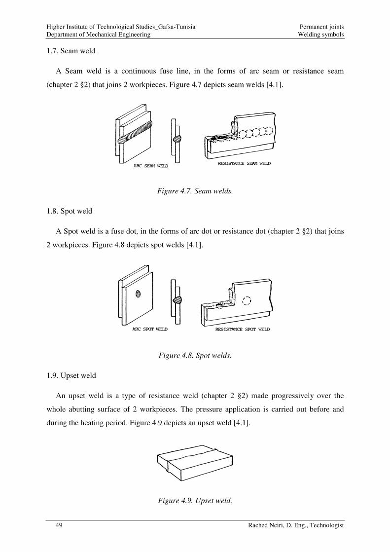
1.7. Seam weld
A Seam weld is a continuous fuse line, in the forms of arc seam or resistance seam
(chapter 2 §2) that joins 2 workpieces. Figure 4.7 depicts seam welds [4.1].
Figure 4.7. Seam welds.
1.8. Spot weld
A Spot weld is a fuse dot, in the forms of arc dot or resistance dot (chapter 2 §2) that joins
2 workpieces. Figure 4.8 depicts spot welds [4.1].
Figure 4.8. Spot welds.
1.9. Upset weld
An upset weld is a type of resistance weld (chapter 2 §2) made progressively over the
whole abutting surface of 2 workpieces. The pressure application is carried out before and
during the heating period. Figure 4.9 depicts an upset weld [4.1].
Figure 4.9. Upset weld.

Higher Institute of Technological Studies_Gafsa-Tunisia Permanent joints Department of Mechanical Engineering Welding symbols
50 Rached Nciri, D. Eng., Technologist
2. Welding symbols chart
The American Welding Society (AWS) provides a comprehensive welding symbols chart
[4.2] (Figure 4.10) that summarizes the welding symbols standardization.
Figure 4.10. Welding symbols chart.

Higher Institute of Technological Studies_Gafsa-Tunisia Permanent joints Department of Mechanical Engineering Welding symbols
51 Rached Nciri, D. Eng., Technologist
3. Basic welding symbol examples
Fillet and groove welds are the most common types of weld in industrial application. This
section presents some relevant basic examples about welding symbols of fillet and groove
welds. These examples will permit to better assimilate the AWS basic welding symbol.
3.1. Welding symbol for fillet welds
3.1.1. Location
Figure 4.11 summarizes the most common welding symbol for fillet weld location [4.3].
Figure 4.11. Location significance of arrow.
3.1.2. Size
Figure 4.12-13 depicts some welding symbols for fillet weld size [4.3].
Figure 4.12. Welding symbols for fillet weld size (weld cross section).

Higher Institute of Technological Studies_Gafsa-Tunisia Permanent joints Department of Mechanical Engineering Welding symbols
52 Rached Nciri, D. Eng., Technologist
Figure 4.13. Welding symbols for fillet weld size (weld cross section and length).
3.1.3. Pitch
Figure 4.14 depicts some welding symbols for fillet weld pitch [4.3].
Figure 4.14. Welding symbols for fillet weld pitch.
3.1.4. All around
Figure 4.15 depicts some welding symbols for all around fillet weld [4.3].

Higher Institute of Technological Studies_Gafsa-Tunisia Permanent joints Department of Mechanical Engineering Welding symbols
53 Rached Nciri, D. Eng., Technologist
Figure 4.15. Welding symbols for all around fillet weld.
3.2. Groove welds
3.2.1. Types
Figure 4.16 depicts some welding symbols for groove weld types [4.4].
Figure 4.16. Welding symbols for groove weld types.

Higher Institute of Technological Studies_Gafsa-Tunisia Permanent joints Department of Mechanical Engineering Welding symbols
54 Rached Nciri, D. Eng., Technologist
3.2.2. Size
Figure 4.17 depicts some welding symbols for groove weld size [4.4].
Figure 4.17. Welding symbols for groove weld size.
4. Specific welding symbol examples
Sometimes, it is helpful to add some specific informations about the welds in the welding
symbols. This section presents some relevant examples about welding symbols that gives
specific information about fillet and groove welds. These examples will permit to better
assimilate the AWS specific welding symbol.
4.1. Back and backing welds
Figure 4.18 depicts some specific welding symbols about back and backing weld carried
out in groove welds [4.4].
13
19
9.5
28.5
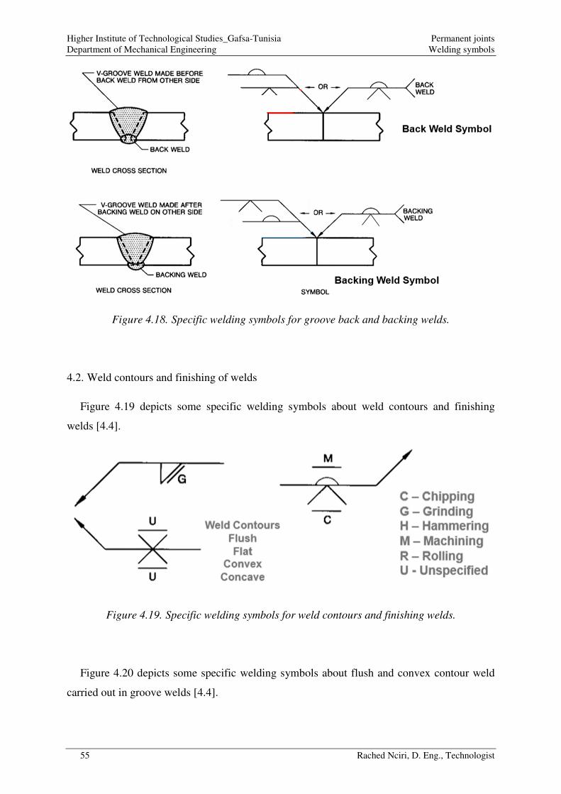
Higher Institute of Technological Studies_Gafsa-Tunisia Permanent joints Department of Mechanical Engineering Welding symbols
55 Rached Nciri, D. Eng., Technologist
Figure 4.18. Specific welding symbols for groove back and backing welds.
4.2. Weld contours and finishing of welds
Figure 4.19 depicts some specific welding symbols about weld contours and finishing
welds [4.4].
Figure 4.19. Specific welding symbols for weld contours and finishing welds.
Figure 4.20 depicts some specific welding symbols about flush and convex contour weld
carried out in groove welds [4.4].

Higher Institute of Technological Studies_Gafsa-Tunisia Permanent joints Department of Mechanical Engineering Welding symbols
56 Rached Nciri, D. Eng., Technologist
Figure 4.20. Specific welding symbols for flush and convex contour welds.
5. References
[4.1] Jeff Grill, Weld Types & Joints, https://weldguru.com/weld-types-joints/#:~:text=%20There%20are%20several%20types%20of%20fillet%20weld%3A,intermittent%20fillet%20welds%20in%20a%20lap...%20More%20 (2019), Access date: 11/26/2020 17:05 GMT
[4.2] American Welding Society, Errata for AWS A2.4-98, Standard Symbols for Welding, Brazing, and Nondestructive Examination. Correction to the Welding Symbol Chart for AWS A2.4-98, pages 106 and 107.
[4.3] Garry Pace, Intro to Welding Symbols Fillet Welds, https://www.youtube.com/watch?v=6L-ku_Bz1r8, Acces date: 11/27/2020 11:39 GMT (Partially modified for educational purposes)
[4.4]Garry Pace, Introduction to Weld Symbols Groove Welds, https://www.youtube.com/watch?v=PpFoi75xJME, Acces date: 11/28/2020 04:03 GMT (Partially modified for educational purposes)

Higher Institute of Technological Studies_Gafsa-Tunisia Permanent joints Department of Mechanical Engineering Resistance/Sizing of weld beads
57 Rached Nciri, D. Eng., Technologist
Chapter 5. Resistance/Sizing of weld beads
The size of a weld bead directly influences its mechanical resistance under the effect of
imposed loads. Thus, it is imperative to correctly size a weld bead on the basis of a calculation
standard (Eurocode 3 Standards). Based on a special knowledge about the weld constituent
elements and the principal types of loads imposed on a weld, this chapter explains how to size
the weld bead knowing the maximum imposed load, and how to evaluate the resistance of a
weld bead knowing its size.
1. Weld constituent elements
1.1. Effective throat thickness
The effective throat thickness a is the distance between the root and the external surface of
the weld bead excluding allowances as it is depicted by Figure 5.1 [5.1].
Figure 5.1. Effective throat thickness [5.1].
It is to note that for a fillet weld, the effective throat thickness should be mm 3≥a [5.2].
1.2. Useful length
The useful length is the actual length from which the crater extremities are subtracted
(starting and fading of the arc). The crater extremity is considered equal to the effective throat
thickness:
aLLL actualuseful ×−== 2
Very short weld beads ( aLL ×<< 6or mm 30 ) cannot be considered in terms of
resistance [5.2].

Higher Institute of Technological Studies_Gafsa-Tunisia Permanent joints Department of Mechanical Engineering Resistance/Sizing of weld beads
58 Rached Nciri, D. Eng., Technologist
1.3. Effective area
The effective area of the weld is depicted by Figure 5.2 [5.1].
Figure 5.2. Effective area for straight and curved welds [5.1].
The effective area A is obtained based on the length L and the effective throat thickness a
of the weld as follows:
bead theof thickness-midat measured Radius :with
weldcurved afor : 2
eldstraight w afor :
m
m
R
aRA
aLA
××=×=
π
2. Principal types of loads

Higher Institute of Technological Studies_Gafsa-Tunisia Permanent joints Department of Mechanical Engineering Resistance/Sizing of weld beads
59 Rached Nciri, D. Eng., Technologist
Three principal types of loads can be imposed on a weld:
2.1. Weld subjected to tensile
When the load is perpendicular to the weld, we talk about the tensile as it is depicted by
Figure 5.3 [5.1].
Figure 5.3. Weld subjected to tensile [5.1].
2.2. Weld subjected to pure shear
When the load is parallel to the weld, we talk about pure shear as it is depicted by
Figure 5.4 [5.1].
Figure 5.4. Weld subjected to pure shear [5.1].
2.3. Weld subjected to tensile and shear
When the load is both perpendicular and parallel to the weld, we talk about tensile and
shear as it is depicted by Figure 5.5 [5.1].
Figure 5.5. Weld subjected to tensile and shear [5.1].

Higher Institute of Technological Studies_Gafsa-Tunisia Permanent joints Department of Mechanical Engineering Resistance/Sizing of weld beads
60 Rached Nciri, D. Eng., Technologist
3. Stresses within welds
Three types of stress are distinguished within a weld as it is depicted by Figure 5.6 [5.1]:
• ⊥σ : Normal stress perpendicular to the throat plane of the weld.
• ⊥τ : Shear stress in the throat plane of the weld and perpendicular to the weld axis.
• //τ : Shear stress in the throat plane of the weld and parallel to the weld axis.
Figure 5.6. Normal and shear stresses within a weld [5.1].
The equivalent Von-Mises stress in the weld is written as:
( )2//
22 3 ττσ +×+= ⊥⊥wσ
The Eurocode 3 Standards postulates that the design resistance of a fillet weld can be
obtained using either the so called “Directional method” or the “Simplified method” [5.2].
Directional method

Higher Institute of Technological Studies_Gafsa-Tunisia Permanent joints Department of Mechanical Engineering Resistance/Sizing of weld beads
61 Rached Nciri, D. Eng., Technologist
The design resistance of a fillet weld using the directional method is written as:
( )22
222 90with 3
M
u
Mw
u//
γ
f.
γβ
fττσ ≤≤+×+ ⊥⊥⊥ σ
Where:
[ ]
[ ] bearing)in plates and pins rivets, bolts, welds,of resistance (for the 1.25factorsafety Partial :
5.3 2-10025 EN from 7 Table fromen tak
joinedpart weaker theofstrength Tensile ultimate Nominal :
5.2 Standards 8-1-1993 EN from 4.1 Table fromen factor takn correlatio eAppropriat :
2 =M
u
w
γ
f
β

Higher Institute of Technological Studies_Gafsa-Tunisia Permanent joints Department of Mechanical Engineering Resistance/Sizing of weld beads
62 Rached Nciri, D. Eng., Technologist
Simplified method
The design resistance of a fillet weld using the simplified method is written as:
2
dvw,dvw,Rdw,Rdw,Edw,
3/ with with
Mw
u
γβ
ffafFFF ==≤
Where:
ickness throat thEffective :
weld theofstrength shear Design :
lengthunit per resistance dDesign wel :
lengthunit per force weld theof ueDesign val :
dvw,
Rdw,
Edw,
a
f
F
F
4. Practical exercises
4.1. Directional method for design resistance of fillet weld/Weld sizing
4.1.1. Weld subjected to pure shear
Fillet welds are subjected to pure shear stress as it is depicted by Figure 5.7 [5.1]:

Higher Institute of Technological Studies_Gafsa-Tunisia Permanent joints Department of Mechanical Engineering Resistance/Sizing of weld beads
63 Rached Nciri, D. Eng., Technologist
Figure 5.7. Fillet welds subjected to pure shear stress [5.1].
It is clear, in this case, that there is no normal stress and that shear stress is parallel to the
weld. There is no perpendicular shear stress.
The design resistance of a fillet weld using the directional method permits to verify the
weld resistance as follows:
( )2
//
2
222 3030Mw
u
Mw
u//
γβ
f
γβ
fτ ≤≤+×+ τ
{
25.1 weldsof Resistance
85.0S275
Mpa 500 examplefor take weMPa;560 toMPa410mm 10t
S275JR
Mpa 10050102
100000
2
2
//
welds2
//
=
=
===
=××
=××
==
M
w
uu
γ
β
ff
La
F τττ
( ) verifiedresistance Weld:MPa 159.470MPa 21.17332
222 ≤≤+×+ ⊥⊥Mw
u//
γβ
fττσ

Higher Institute of Technological Studies_Gafsa-Tunisia Permanent joints Department of Mechanical Engineering Resistance/Sizing of weld beads
64 Rached Nciri, D. Eng., Technologist
Also, it is possible to determine the minimum size of weld (minimum area of the weld:
minimum length for a fixed throat or minimum throat for fixed length) that permits to resist to
the imposed load as follows:
( ){ 2
welds22
//
stressshear Pure
2
222
2333
Mw
u
Mw
u
Mw
u//
γβ
f
La
F
γβ
f
γβ
fττσ ≤
××≤≤+×+ ⊥⊥ τ
For a fixed throat a=10 mm, the minimum length of the weld is written as:
4342144 344 21 min
min
mm 40.18500102
25.185.01000003
23 2
L
L
u
Mw LLfa
γβFL ≥
××××≥
××××
≥
It is to note here that aL ×≤ 6min (very short weld cannot be considered in terms of
resistance). So, this minimum length that can be used is mm 606 =×= aL .
4.1.2. Weld subjected to tensile and shear
Fillet welds are subjected to tensile and shear stresses as it is depicted by Figure 5.8 [5.1]:
Figure 5.8. Fillet welds subjected to combined tensile and shear stresses [5.1].
In this case, that there is a normal stress and perpendicular shear stress applied on the
welds.

Higher Institute of Technological Studies_Gafsa-Tunisia Permanent joints Department of Mechanical Engineering Resistance/Sizing of weld beads
65 Rached Nciri, D. Eng., Technologist
The design resistance of a fillet weld using the directional method permits to verify the
weld resistance as follows:
( )22
222 90with 03
M
u
Mw
u
γ
f.
γβ
fτσ ≤≤+×+ ⊥⊥⊥ σ
{
{
25.1 weldsof Resistance
8.0S235
Mpa 420 examplefor take weMPa;510 toMPa360mm 9t
S235JR
MPa 13.8985722
150000
22
22
2
welds2
welds2
=
=
===
=×××
==
××===
×××==
⊥⊥
⊥
⊥
M
w
uu
γ
β
ff
La
F
La
F
τσσττ
σσ
( ) verifiedresistance Weld:MPa 4.302MPa 13.89 with MPa 204MPa 26.178
90with 03
22
222
≤≤
≤≤+×+ ⊥⊥⊥M
u
Mw
u
γ
f.
γβ
fτσ σ
Also, it is possible to determine the minimum size of weld (minimum area of the weld:
minimum length for a fixed throat or minimum throat for fixed length) that permits to resist to
the imposed load as follows:
( )
( )
2
22
222stressshear and tensileCombined
22
222
2
90with 03
90with 3
Mw
u
M
u
Mw
u
M
u
Mw
u//
γβ
f
La
F
γ
f.
γβ
fτσ
γ
f.
γβ
fττσ
≤××
≤≤+×+
≤≤+×+
⊥⊥⊥
⊥⊥⊥
σ
σ
For a fixed throat a=7 mm, the minimum length of the weld is written as:
434214434421 min
min
mm 36.0842072
25.18.0150000
22
L
L
u
Mw LLfa
γβFL ≥
××××≥
××××≥
It is to note here that aL ×≤ 6min (very short weld cannot be considered in terms of
resistance). So, this minimum length that can be used is mm 426 =×= aL .

Higher Institute of Technological Studies_Gafsa-Tunisia Permanent joints Department of Mechanical Engineering Resistance/Sizing of weld beads
66 Rached Nciri, D. Eng., Technologist
For a fixed length L=45 mm, the minimum throat of the weld is written as:
43421
4434421 min
min
mm 5.61420452
25.18.0150000
2
2
a
a
u
Mw aafL
γβFa ≥
××××≥
××××≥
4.2. Simplified method for design resistance of fillet weld
The shear resistance of a welded end plate is depicted by Figure 5.9 [5.4]:
Figure 5.9. Shear resistance of welded end plate [5.4].
{ Rdw,
kN 500
Edw,Rdw,Edw, VVFF ≤≤
{ {ah
aγβ
fp
Mw
u
LFV×−
×
××=2
3/
Rdw,Rdw,
2
2
25.1 weldsof Resistance
85.0S275
Mpa 450 examplefor take weMPa;560 toMPa410mm 10t
S275JR
mm 184mm 8a
mm 200
2 =
=
===
=
=
=
M
w
uu
p
γ
β
ff
Lh

Higher Institute of Technological Studies_Gafsa-Tunisia Permanent joints Department of Mechanical Engineering Resistance/Sizing of weld beads
67 Rached Nciri, D. Eng., Technologist
kN 88.719N/mm 2.1956
mm 8
25.1
85.0
MPa 450
mm 184
Rdw,
Rdw,
2
==
==
==
=
VF
a
γ
β
f
L
M
w
u
verifiedresistance Weld:kN 88.719kN 500 Rdw,Edw, =≤= VV
5. References
[5.1] Fabien Segovia, Dimensionnement de soudures avec l'eurocode 3, https://www.youtube.com/watch?v=PPJD3hXPhL8&t=126s, Access date: 01/03/2021 22:39 GMT
[5.2] European Standard, Eurocode 3: Design of steel structures - Part 1-8: Design of joints, EN 1993-1-8:2005 (E)
[5.3] British Standard, Hot rolled products of structural steels —Part 2: Technical delivery conditions for non-alloy structural steels, BS EN 10025-2:2004
[5.4] Dilakshana Mayadunne, Steel Connections | Welded Joint Design | Pinned Joints | Rigid Joints (Fixed) | Eurocode 3 | EN1993, https://www.youtube.com/watch?v=pEzuLkMzHzM, Access date: 01/03/2021 22:49 GMT

Higher Institute of Technological Studies_Gafsa-Tunisia Permanent joints Department of Mechanical Engineering Other types of permanent joints
68 Rached Nciri, D. Eng., Technologist
Chapter 6. Other types of permanent joints
Welding is considered as the most common type of permanent joint in the field of metallic
construction. However, there are very useful other types of permanent joints used in metallic
constructions, mainly the brazing, the riveting and the crimping. This chapter presents each
one of these permanent joints and their industrial applications. The choice of the appropriate
joint is carried out based on the specifications involved by the appropriate industrial
applications.
1. Brazing process
1.1. Principle of the brazing process
The brazing is a joining process that permits to create a permanent joint between similar or
dissimilar metals using a filler metal that present lower melting point than the adjoining metal.
The melting point of the filler metal is above 450°C. A protective flux, such as Borax, is
applied on metal parts in order to prevent oxidation. Four principal types of brazing are
distinguished:
• Torch brazing: Figure 6.1 [6.1] depicts the principle of torch brazing. The torch
brazing process uses a hot gas jet from a torch towards a joint in order to heat the
workpieces and melt the filler metal. Thus, a joint is created between the workpieces.
Since the melting point of the filler metal is considerably lower than the oxidation
temperature of the workpieces, the joint is protected against oxidation.
Figure 6.1. Torch brazing principle [6.1].
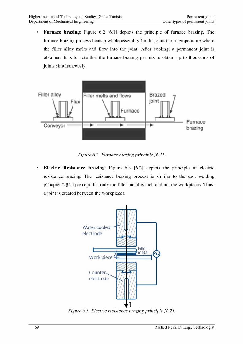
Higher Institute of Technological Studies_Gafsa-Tunisia Permanent joints Department of Mechanical Engineering Other types of permanent joints
69 Rached Nciri, D. Eng., Technologist
• Furnace brazing: Figure 6.2 [6.1] depicts the principle of furnace brazing. The
furnace brazing process heats a whole assembly (multi-joints) to a temperature where
the filler alloy melts and flow into the joint. After cooling, a permanent joint is
obtained. It is to note that the furnace brazing permits to obtain up to thousands of
joints simultaneously.
Figure 6.2. Furnace brazing principle [6.1].
• Electric Resistance brazing: Figure 6.3 [6.2] depicts the principle of electric
resistance brazing. The resistance brazing process is similar to the spot welding
(Chapter 2 §2.1) except that only the filler metal is melt and not the workpieces. Thus,
a joint is created between the workpieces.
Figure 6.3. Electric resistance brazing principle [6.2]. I

Higher Institute of Technological Studies_Gafsa-Tunisia Permanent joints Department of Mechanical Engineering Other types of permanent joints
70 Rached Nciri, D. Eng., Technologist
• Dip brazing: Figure 6.4 [6.1] depicts the principle of dip brazing. The dip brazing
process permits to obtain simultaneous multiple joints with different workpiece
thicknesses. It consists, firstly, to fix the workpieces to be joined and to apply the
brazing compound (filler metal+flux) on the joint interfaces (contact surfaces between
the workpieces) in slurry form. The assembly is then pre-heated up to a temperature
right below the melting point of the filler metal. This will permit to reduce the stay
time of the workpieces to be joined in the bath of molten salt. It is to note that the
application of flux permits to keep the filler metal in place while being dipped
(submerged) in the molten salt bath which acts as a heat transfer medium. Finally, the
assembly is completely dipped into the molten salt bath. As the melting of the filler
metal begins, the flux dissolves in the bath and the filler metal occupies the joint
space. Thus, permanent joints between the workpieces are created.
Figure 6.4. Dip brazing principle [6.1].
1.2. Industrial applications of the brazing process
The brazing process is appropriate for the industrial applications that involve permanent
joints presenting the main following specifications [6.3]:
• Joint between workpieces with small overall size (smaller than the usual overall size
of the welded workpieces).
Before brazing
After brazing

Higher Institute of Technological Studies_Gafsa-Tunisia Permanent joints Department of Mechanical Engineering Other types of permanent joints
71 Rached Nciri, D. Eng., Technologist
• Joint between workpieces with similar and dissimilar metals.
• Large mass production.
2. Riveting process
2.1. Principle of the riveting process
The riveting is a joining process that permits to create a permanent joint between similar or
dissimilar metals using a rivet, a backing up bar and a die as it is depicted by Figure 6.5 [6.4].
It is to note that the riveting can be carried out hot or cold, manually or mechanically. The
holes through which rivets are applied can be made by punching or drilling.
Figure 6.5. Riveting principle [6.4].

Higher Institute of Technological Studies_Gafsa-Tunisia Permanent joints Department of Mechanical Engineering Other types of permanent joints
72 Rached Nciri, D. Eng., Technologist
The riveting process can create both lap joint and butt joint (single, double, chain and Zig-
Zag riveted joint) as it is depicted by Figure 6.6 [6.5].
Figure 6.6. Types of riveted joints [6.5].
It is to note that there are some rules that must be respected when carrying out a riveting
operation (Figure 6.7 [6.6]).
Figure 6.7. Principal riveting rules [6.6].
d3P
Pitch :P
t0.625tt
strap double of sThicknesse: t,t
t125.1t
strap single of Thickness:t
t6d
plates joined theof Thickness :t
rivet ofdiameter :d
21
21
1
1
×=
×==
×=
×=

Higher Institute of Technological Studies_Gafsa-Tunisia Permanent joints Department of Mechanical Engineering Other types of permanent joints
73 Rached Nciri, D. Eng., Technologist
2.2. Industrial applications of the riveting process
The riveting process is appropriate for the industrial applications that involve permanent
joints presenting the main following specifications [6.7]:
• Joints between workpieces for which the thermal effects must be avoided.
• Joints between workpieces having poor weldability.
• Joints between workpieces with heterogeneous materials (asbestos friction lining-steel
for example).
• Joints between workpieces subjected to intense vibrations.
• Joints between workpieces in aluminum aircraft structures.
3. Mechanical crimping process
3.1. Principle of the crimping process
The mechanical crimping is a joining process that permits to create a permanent joint
between metal (or other ductile material) workpieces by bending (deforming) one or both of
them to hold the other. The crimping allows avoiding the Heat-Affected Zone (HAZ)
encountered with welding joints. Figure 6.8 [6.8] depicts the principle of crimping process.
Figure 6.8. Crimping principle [6.8].
3.2. Industrial applications of the crimping process
The crimping process is appropriate for the industrial applications that involve permanent
joints presenting the main following specifications [6.9]:

Higher Institute of Technological Studies_Gafsa-Tunisia Permanent joints Department of Mechanical Engineering Other types of permanent joints
74 Rached Nciri, D. Eng., Technologist
• Joints between sheet metal workpieces (Cladding, boilermaking, etc.).
• Joints between metal pipes (ductwork in ventilation and air conditioning systems,
rainwater pipe, etc.).
The crimping process is also used in:
• Reducing pipe diameter in order to ensure a male (uncrimped pipe)-female
(crimped pipe) joint. The diameter reduction is carried out by transforming the
circular profile at the end of the pipe into a wavy profile. It is to note that this
specific “crimping” joint is neither permanent nor waterproof.
4. References
[6.1] Makers Legacy, Brazing Methods, https://makerslegacy.com/brazing/what-is-brazing/, Access date: 01/10/2021 14:41 GMT
[6.2] Hartmut Schmoor , Brazing processes, http://www.schmoor-brazing.com/en/brazing-processes.html, Access date: 01/10/2021 14:47 GMT, Partially modified for educational purposes
[6.3] William Harris, Brazing Applications and Advantages, https://science.howstuffworks.com/brazing5.htm, Access date: 01/21/2021 08:49 GMT.
[6.4] KTU Web, Introduction to Riveted Joints - A Quick Review of Different Types of Rivet Joints, https://www.youtube.com/watch?v=YQoegtLFL5A, Access date: 01/20/2021 20:55 GMT
[6.5] Mecholic, Types of Riveted Joints – Lap Joint, Butt Joint, Single Strap, Double Strap, Chain and Zig-Zag Riveting, https://www.mecholic.com/2018/10/types-of-riveted-joints.html, Access date: 01/20/2021 21:04 GMT
[6.6] ITI LIFE GYAN, BUTT JOINT - Single Riveted (Single Strap) By Surender Sharma (Rivets Video-8), https://www.youtube.com/watch?v=Hwx48ZEjhO4, Access date: 01/21/2021 09:11 GMT
[6.7] Club Technical, Rivet and Riveted Joints, Applications, Advantages, Disadvantages, https://clubtechnical.com/rivet, Access date: 01/21/2021 11:27 GMT
[6.8] Christian Weddeling, Electromagnetic Form-Fit Joining, Thesis for: Dr.-Ing. in Mechanical EngineeringAdvisor: A. Erman Tekkaya, Glenn S. Daehn, December 2014, https://www.researchgate.net/publication/272823106_Electromagnetic_Form-Fit_Joining, Access date: 01/21/2021 12:19 GMT
[6.9] Designing Buildings Wiki, Crimp, https://www.designingbuildings.co.uk/wiki/Crimp, Access date: 01/21/2021 11:59 GMT