7672 Phenology of black cherry and eastern tent caterpillars
Upload
khangminh22Category
view
0download
0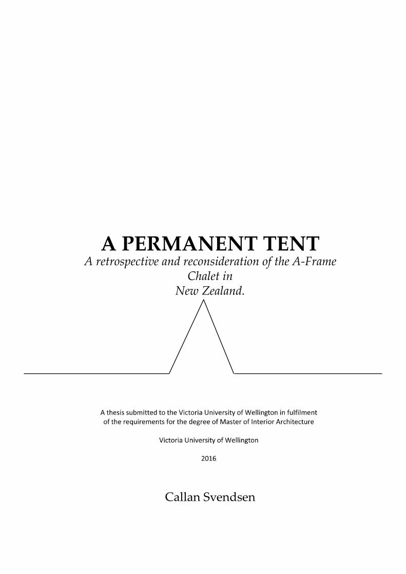
A PERMANENT TENTA retrospective and reconsideration of the A-Frame
Chalet in New Zealand.
Callan Svendsen

I
ACKNOWLEDGEMENTS
It’s customary for an author to thank all the people who helped them with their book. But as this is a thesis, I’d like to thank some of the people who helped me with my journey through the School
of Architecture.
Peter Anderson for his support and belief in me over the past fi ve years. None of this would have been possible without you, thank
you.
Christina Mackay, thank you for your wisdom and being a con-stant sounding board. You were the reason I chose to pursue
Interior Architecture.
To the greats here and the other place, you continue to be a con-stant source of inspiration. In particular, the late great Sir Ian
Athfi eld and the positively timeless Roger Walker. Your seminal work ignited my imagination from a very young age. I am
eternally in awe of your contribution to architecture.
I’d also like to acknowledge Gordon Duff , Sam Sherriff and Sco# Kersley who took time and patience to invest in the formative
years of my architectural interest.

II
“The tent, moreover, was not something that replaces the ground on which it sits. It either decayed (or grew) after we stopped using it, or it became something we
took with us when we moved on to the next campsite. Architecture here is no more and no less than an extension of our clothes, our furniture, and our tools into a
form that can, if only for a night, enclose us. It is at the same time no more and no less than a conventionalisation of the nature we still fi nd around us.”
BETSKY, Furnishing the Primitive Hut
“Alteration is more like a duet than a solo. It is about the art of response as much as it is the art of individual genius; it sets out to make a concord between the new and existing, or even a discord. Either way, it is a proposal concerning how the design-
er may form a response in their new work to the host building”
FRED SCOTT, On Altering Architecture

III
Contents1. Abstract...............................................................................1
1.1 - Research Question... 1 1.2 - Introduction... 2 1.3 - Methodology... 5
2. Historical Backgrond........................................................7 2.1 - The A-Frame in America... 7 2.2 -‘Leisurama’ ... 10 2.3 - New Zealand... 12 2.4 - Sunset Magazine... 16
3. The Site.............................................................................19 3.1 - Ruapehu... 19 3.2 - Subject A-Frames... 21
4.Case Studies......................................................................33 4.1 - ‘Trigon’... 33 4.2 - David Hellyers Cabin # 4... 34
5. Philosophical Strategy...................................................42 5.1 - Fred Sco! , On Altering Architecture... 42 5.2 - Chad Randl, A-Frame... 44 5.3 -The ICOMOS Charter... 46
6. Design Strategy...............................................................47 6.1 -‘Insertion’- Re-readings... 47
7. Preliminary Design........................................................48 7.1 - Initial conceptual response... 48 7.2 - Iteration One, Prefabrication... 52 7.3 - The Shroud...55
8. Developed Design..........................................................61 8.1 - Materials and Technology... 64 8.2 - The Core... 66 8.3 - Kitchen & Futuniture... 70 8.4 - Bathrooms & Showers... 73
9. Project Documentation..................................................83
10. Conclusion.....................................................................96 10.1 - Critical refl ection... 97 10.2 - Thesis Conclusion... 98
11. References......................................................................99 11.1 Image Sources... 101

This page intentionally left blank.

1
1. Abstract
The mid twentieth century A-Frame chalet holds a special place in the memories of generations of New Zealanders. Reminiscent of summer and winter getaways, it is perhaps the most poignant architectural representation of leisure and relaxation.
The novelty of unconventional sleeping arrange-ments, intimate spatial dynamics and the somewhat ephemeral nature of the typology combined to imbue the A-Frame with a strong emotional association. This research intends to harness the nostalgic connotations and use this, along with contemporary interior archi-tectural theory, to reinterpret the A-Frame as a relevant form of accommodation suitable for twenty-fi rst century vacationers and permanent inhabitants alike.
Early New Zealand A-Frames were supplied as kit sets to be erected by owners with rudimentary knowl-edge of construction techniques. This ‘low-end’ means of arrival, understandable given the purpose of the dwelling, resulted in a typology that was regarded as a lesser relative to the primary (and more conventional) home. Awkward interior spaces were regarded as novel and tolerable for the duration of the vacation.
There is limited academic publication on the A-Frame Chalet and its place in New Zealand architectural history. The aim of this research is to identify the key proponents of the style and use this as a base for a modern reinterpretation encompassing spatial and material issues.
The modern tendency toward compact housing and preservation of architecturally distinctive buildings favours a new appreciation of the A-Frame. A reevaluation will address limitations of the original and re-interpret the A-Frame from nostalgic novelty to spa-tially responsive contemporary architecture.
How can an existing A-Frame chalet be rede-signed to refl ect the history of the typology and ad-dress spatial desires of modern antipodean user groups? With the application of interior architectural theory, can the A-Frame form be elevated from nostalgic nov-elty to spatially responsive contemporary architecture?
1.1 Research Question
Image 1: Early Sketch of A-Frame.

2
1.2 Introduction
The triangle’s innate structural integrity has been employed for centuries as an effi cient and robust means of shelter. Examples of the form can be identifi ed in most primitive cultures as permanent dwellings or temporary refuge. The traditional tent form is an archetypal representation of man’s intrepid nature, the manipulation of environment through architectural response.
This research regards the A-Frame as an evolution of the traditional tent form, the most elemental of forms merged with the permanence of a conventional built dwelling - the permanent tent. The strength and longevity of conventional building materials integrated with the tradition of the form and combined to become the A-Frame Chalet.
Material availability and economy has determined the purpose and life span of the form. Primordial examples employed animal hide as a means of weather protection, tethered to a rudimentary timber frame (Randl 12). Progressively technology has improved the usability and longevity of the shelter, indeed the form itself has morphed into an inhabitable version of the most basic of built forms.
Evocative of its European roots, the form became synonymous with Alpine recreation. The evolution of the form was not limited to sub-zero locales however, as the form has been successfully applied in coastal and temperate climates. A tent for all seasons.
Image 2: Early Scandinavian Tents. Date unknown.

3
And in New Zealand? The nation is steeped in ‘do it yourself’ tradition, an enduring pioneering spirit that has permeated our culture since colonisation.
Prefabricated dwellings then, should by their nature, appeal to the kiwi consciousness. The ability for the purchaser to take a ‘hands on’ approach to their build should have been an easy sellling point for the brazen entrepreneur.
DIY perhaps, but New Zealander’s aesthetic aspirations are more inherent than one would like to admit. Individuality and prefabrication is a curious dichotomy that the antipodean psyche fi nds diffi cult to process. Indeed, this dilemma has been pertinent since the early Railway Houses; identical in form in detail, unique in personal décor expression. What can’t be inherently altered can be superfi cially gilded as an expression of the owners taste.
The ‘Prefab’ concept was at its commercial peak in the early 1970’s with the McRae-way ‘A-Frame’ Chalet. Though adaptable in detail and available in three diff erent variations, the McRae-way was the harbinger of the acceptance of kitset homes. It is of note that at this time society had a much more relaxed approach to architecture. Sir Ian Athfi eld and Roger Walker, the enfants terribles of New Zealand architecture had already unleashed their fanciful confections to an unsuspecting nation, inciting a dramatic wave of architectural expres-sion.
Figure 3 : Roger Walker’s Johnson House 1970. Note steep roof pitch and skylights.

4
High pitched roofs were favoured over their lower slung counterparts, windows were placed at unconventional heights, orthodox layouts abandoned in a knee jerk reaction to the traditions of yore. Walker’s early Wellington Club project 1968-1972 (dem. 1985) (Figure 4) represented a perfect embrace of the ‘shift’. The staid peerage of the Club embracing the radical proposal was perhaps the ultimate triumph, Walker himself said of the building;
“When I was designing the Wellington Club, I felt intui-tively that some time in the future such a valuable site could be threatened by the demolition contractor and replaced with a twenty storey tower... so I deliberately over-structured the building - it’s massively strong - in the hope that the resultant heavy cost of demolition might dissuade future entrepreneurs from destroying it’ (Melling, 1)
In 1972, Lower Hu! ’s Dowse Museum curated an exhibition of the work of Walker, Athfi eld and Sco! et al. entitled ‘The New Romantics’ (Architecture Now). Also included in the exhibition was the work of Claud Megson, who, according to Peter Beaven (architect and author of the cited article) “had a remarkable talent for astonishing manipulation of small spaces into great spatial experiences”(Beaven). On one hand you have outlandish built forms, in the other, tangible evidence that small spaces can be appreciated far beyond the sum of their parts. Small spaces and strong forms. A pa! ern was starting to emerge.
Figure 4: Roger Walker’s Wellington Club c.1984
Gone were the staid conventions of previous decades, the 1970’s were a time of great architectural awakening. New Zealand was listening and primed for a change. One might even a! ribute Walker and Athfi eld with paving the road of acceptance for the A-Frame Chalet in New Zealand.
The story, of course, does not start and end there. It is in fact a case of déjà vu, heralded by post-war America and an architect by the name of Andrew Geller.
5
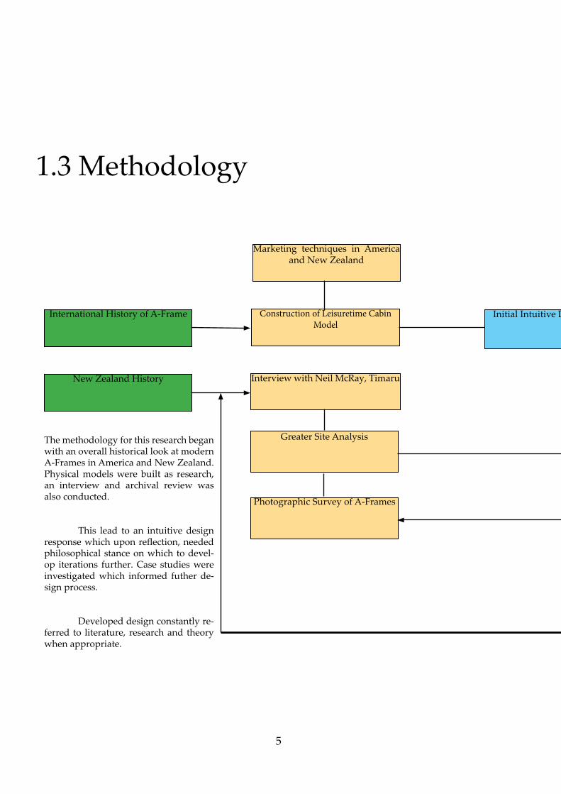
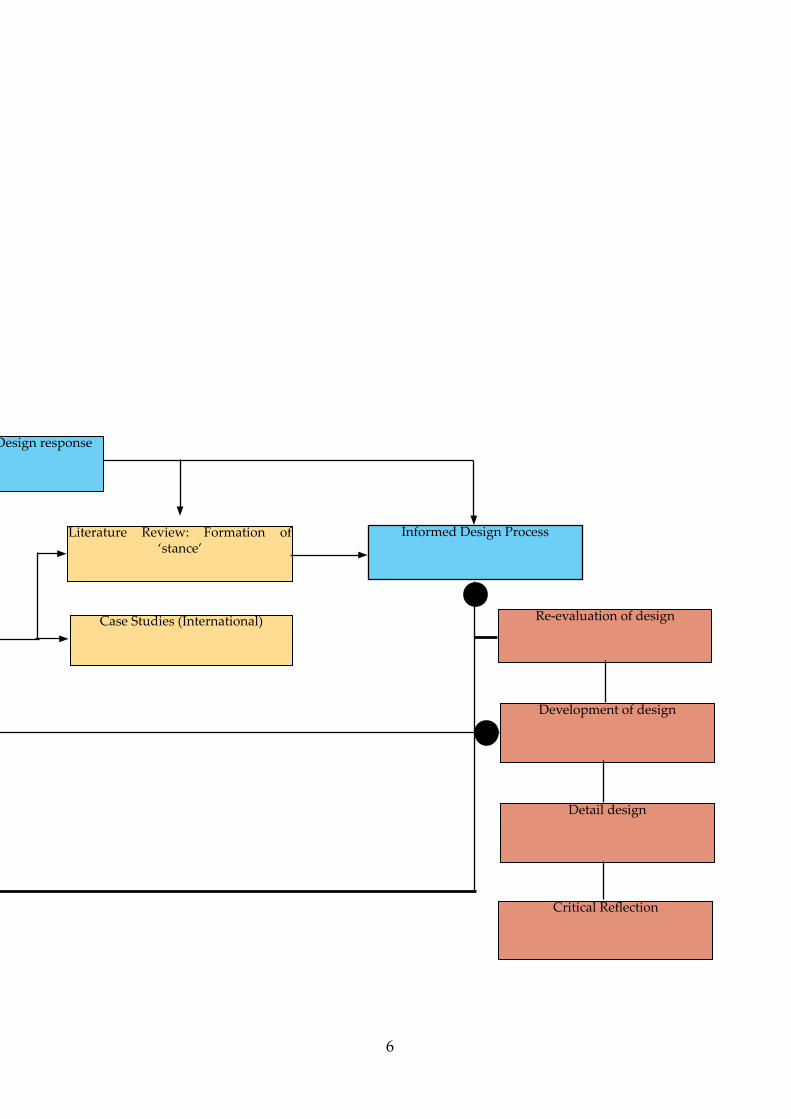
1.3 Methodology
International History of A-Frame
New Zealand History
Construction of Leisuretime Cabin
Model
Interview with Neil McRay, Timaru
Greater Site Analysis
Photographic Survey of A-Frames
Marketing techniques in America and New Zealand
Initial Intuitive Design response
The methodology for this research began with an overall historical look at modern A-Frames in America and New Zealand. Physical models were built as research, an interview and archival review was also conducted.
This lead to an intuitive design response which upon refl ection, needed philosophical stance on which to devel-op iterations further. Case studies were investigated which informed futher de-sign process.
Developed design constantly re-ferred to literature, research and theory when appropriate.
6
e Design response
Re-evaluation of designCase Studies (International)
Literature Review: Formation of ‘stance’
Development of design
Detail design
Critical Refl ection
Informed Design Process

7
2. Historical Background2.1 The A-Frame in America
It is generally considered that architect Rudolph Schindler was the fi rst to introduce the A-Frame to America. In 1936, Schindler designed, for Gisela Bena" i, an open plan gable ended holiday home; a simple structure that predated the A-Frame’s period of popularity by some twenty years. In order to circumvent the planning regulations of the exclusive resort, Schindler rebranded the dwelling as ‘Norman Style’ (Old House Journal). Whilst not adhering to a conventional style, the A-Frame was tolerated under a guise. That it took another twenty years for the form to be considered an architectural style of merit beyond mere rudimentary shelter and storage speaks volumes.
The fi rst iteration of an A-Frame to capture the imagination of the public was designed by John Campbell and entitled the ‘Leisure House’ (Toolan).Campbell exhibited his building at the 1951 San Francisco Arts festival and experienced enough interest to begin selling the plans and kit sets. It was not the novelty of the form that necessarily endeared the style to the public. It was in fact the network of suppliers throughout the west coast that, combined with artistic impressionism, marketed that A-Frame as a desirable must have for the aspiring middle-class.
Public interest in the A-Frame acted as the catalyst by which architects began experimenting with the form in earnest. The success of Campbell’s ‘Leisure house’ inspired clients to seek a more personalised iteration of the typology.
Figure 5: Bena! i A-Frame plans, 1936.

8
American architect Andrew Geller (1924-2011) took Campbell’s cue one step further by removing the kitset aspect and introducing bespoke opportunity. Geller’s beach houses were just that - Beach Houses; thus, the Alpine vernacular so imbued in the style was seemingly at odds with its adopted environment. Geller addressed this shift in application by utilising modern (at the time) materials with limited thermal considera-tions as appropriate to the temperate environment. The key driver for the application of the form was the innate strength of the triangular form and its ability to resist high wind loads in coastal areas. It should be noted that Gellers later iterations of the form steered away from the purity of the ‘A’ shape, though fundamentally remained true to the nature of unconventional provocative architecture.
The fi rst of Geller’s A-Frame’s was the Elizabeth (Be� y) Reese House in Long Island, New York. This gained exposure after being featured in the New York Times in May 1957 (Gordon 22) . Reese provided a carte blanche brief; the only prerequisite being “intimate contact with the sea and sand, instant release from her busy schedule in the city” (Gordon 24)
Sadly short lived, the Reese House was destroyed by a hurricane after only months in existence. The client was undeterred. Geller was promptly commissioned to design a second Reese house, this time on an inland wooded site. The architecture responded to the se� ing in as dynamic a way as the original did, though not adhering to the A-Frame style.

9
What makes the fi rst Reese house unique is the A-Frame structure coupled with adaptable interior spatial forms. This resulted in a building that invited casual occupation, its playful spatial dynamic countered with its coastal location captured the imagination of the American public and heralded the start of Geller’s illus-trious ‘Vacation House’ period.
The interior of the house was pared back; simple timber fi nishes and no insulation suggested only seasonal inhabitation. Geller did, however, consider the solar gains of the interior by designing a brise soliel1 that provided space for private sunbathing whilst protecting the ground fl oor living area from the sun (Gordon 104). A se" ee was built into the living room that doubled as extra bedding should the need arise. Here we see spatial effi ciencies be-ing considered from the outset.
Reese’s own bedroom was located on the fi rst fl oor of the structure and accessed by means of a moveable ladder. Spatial division was achieved by fabric sails, denoting the ephemeral nature of the interior and transient nature of inhabitation.
Geller’s early career was built upon the beach house ‘movement’ in Montauk, Long Island. He went on to design numerous iterations of the form, each with its own personality particular to the whim of the client and the architect’s interpretation of the brief. Geller’s popu-larity, though not initially appreciated in architectural circles, laid in his ability to blend whimsical folly with practical and spatially aware architecture. This particular combination of facets could be applied to the early work of Walker and Athfi eld in New Zealand, be it some twenty years later.
1.Brise soliel, a fi xed or movable device designed to black the direct entrance of sun rays into a building (Harris 74)
Figure 6: Be� y Reese House, Montauk c. 1956

10
2.2 ‘Leisurama’
The success and potential fi nancial reward of Geller’s beach houses did not go unnoticed by developer Herbert Sadkin. Commercial success, though tasted by Geller, had the hallmarks of a highly lucrative proposition. Geller’s initial designs continued through iterations in his private commissions. Economy of scale however, dictated that a more conventional approach be taken and the design be reined in to fi t a more conventional method of construction. Sadkin commissioned noted industrial designer Raymond Loewy to create a housing project of beach houses. Loewy assigned the task to Geller, at the time the vice-president of his Housing and Home division (Sahre 170). To be" er understand the project we should consider that at the time Loewy was focusing on automotive design. This mind-set of production line manufacture coupled with Gellers’ innovative back catalogue should, all things considered, have been a resounding success.
Leisurama was introduced to the public in 1964, courtesy of the seventh fl oor of the Macy’s department store in Manha" an (Sahre 26). A full sized ‘showhome’ was erected, and a catalogue of additional extras was available to personalise the homes. The full ‘turn-key’ package included furniture, linen and the choice of varieties of cutlery. Here we see the interior architecture extending beyond the building envelope and operating on a much more intimate scale.
If Leisurama is the mid-sixties acme of architectural ‘off the shelf’ customisation, its automotive counterpart the Ford Mustang can be considered the parallel accessory. What be" er then, for the customers that opted for the ’Carport’ option, but to have the motorised manifestation of the Leisurama ethos nestled next to their own slice of pre-packaged paradise. Released in 1964, Ford’s Chief Executive Lee Iacocca commissioned a car for the people; an off the shelf creation with extras only limited by the customer’s imagination and budget. This mode of purchasing refl ected the buoyant post-war economic climate and the idea of the product being as close to bespoke as an ‘off the shelf’ consumable could be.
Figure 7: Artists Impression of ‘Leisurama’ Holiday Home c. 1960’s
Figure 8: ‘Leisurama’ advertising c. 1960’s

11
The base model was the medium upon which a catalogue of variations and accoutrements could be added according to the taste and budget of the customer. As with Leisurama, the economy of the Mustang was achieved by deriving parts from existing models negating the extra tooling costs for bespoke components. One could surmise the process to be as close to pre-cut framing as an automobile could be. Initial sales were stronger than the 100,000 units anticipated, and within 18 months of its release the Mustang had exceeded one million units. (Iacocca 79)
Iacocca’s vision was to produce a vehicle that appealed to all markets, from the entry level purchaser to the high end customer. Alvin Toffl er’s Future Shock addresses consumerism and mass production, succinctly noting that “the customer wanted custom-like cars that would give them the illusion of having one-of-a-kind” (Toffl er 244). This is the same ethos that applied to the Leisurama customer.
Where the parallels end, though, is the fi nancial reward endowed on the subject companies. Beleaguered by unanticipated fi scal setbacks, Leisurama failed to deliver on its promise. Production was paused before the completion of 200 units, 8oo short of the original forecast, due to unforeseen cost increases (Sahre 22). Land value had soared, and reticulation services into the barren reaches of Long Island proved to be a fi nancial hindrance that absorbed profi t as voraciously as the Ford V-8 guzzled the seemingly inexhaustible supply of gasoline.
The post-war affl uence and availability of coastal land, once the catalyst for the style, became its downfall. With land prices exponentially increasing a new type of clientele was paying a# ention to the shores of Montauk. No longer was it acceptable for one’s second home to be the playful folly of leisure. The holiday home was now seen as an extension of the primary residence and representative of all of the material aspirations of its owner.
If Leisurama is seen as the evolution of the ‘off the shelf’ ethos of the original A-Frame concept we can identify parallels on a domestic level. Cheap housing, though not a new concept in New Zealand, was not truly embraced until the 1970’s. While previous ‘kitset’ houses were available (1920’s New Zealand Railway Houses for example) they lacked the ability to be customised beyond superfi cial decoration.
The earliest example of kitset housing stemmed from one man’s vision to combine cheap construction techniques, self-buildability and customisation. Somewhat unsurprisingly, the A-Frame proved to be the perfect form for the vision to be realised.

12
2.3 New ZealandMcRae-way Homes, TimaruInterview with Neil McRae conducted May 2015.
To gain a greater understanding of the early history of the A-Frame in New Zealand, I conducted an interview with Neil McRae, son of the late Ian McRae. The pupose of the interview was to explore archival documentation held at the offi ce and glean an appreciation for the social and economic climate of the time that gave rise to the success of the McRae-way A-Frame. The McRae-way A-Frame is regarded as the fi rst mass produced example of the typology in New Zealand.
Ian McRae was a self-taught builder, his early work involved erection of garages for a local developer. This experience prompted McRae to investigate low-cost build techniques, and resulted in the fi rst commercially available pre-cut A-Frame in New Zealand.
Timaru based McRae-way Homes started the pre-cut A-Frame’s in 1972 under the name of ‘Precut Cha-lets’ off ering three variations of the design A1, A2 and A3; one, two and three bedrooms respectively. The company was renamed McRae-way Homes in 1974. At this time the company exported a kitset chalet to Japan to test the international market, this met with limited successhowever.
The concept became synonymous with McRae-way Homes and featured in their contemporary advertising. Match boxes illustrated with an image of the A-Frame (Figure 9) are still in existence and provide a curious glimpse of 1970’s advertising.
Figure 9: McRae-way Homes matchbox advertising c. 1974

13
The premise for the design was effi cient use of materials and ease of building. It was the house that you could build yourself. This economical and ‘hands-on’ ap-proach appealed to the New Zealand psyche, traditionally steeped in the DIY tradition. Alterations to the standard form were achieved by extending the longitudinal dimension, keeping the ‘A’ form unchanged.
The original A-Frame was superseded in 1978 by a more conventional 8ft high perimeter wall with a 45 degree pitch named ‘Colonial’ and ‘Pioneer’ series. The ethos of material effi ciency remained; Neil McRae pointed out that the 45 degree cut meant a reduction in wastage of plasterboard linings. The same applied to the 45 degree cut of rafters, where the cut again eliminated wastage and improved time effi ciency. While widely regarded as creating the ‘McRae’ look, the co� ages owe a lot of their construction technique to the design of the original A-Frame. The evolution of this progression of iteration was similar to that of Geller’s ‘Leisurama’ foray some twenty years prior.
Figure 11: McRae family hoilday house, Queenstown.
Figure 10: Elevations of ‘Pioneer’ series, c. 1980’s

14
If the A-Frame acted as a test bed for effi cient building techniques, the ‘Pioneer series’ built on this success but in a more socially palatable form.Again, we could a� ribute this with the evolution of esteemed New Zealand architects, in particular Athfi eld and Walker’s ‘Neo-Colonial’ examples that became popular at this time also.
When comparing the Pioneer series with the A-frame a number of similarities can be identifi ed, in particular the shifting from unconventional form to theconventional. Spatial limitations of the sloped wall/roof were addressed by means of conventional 8ft stud height on the ground fl oor. Dormer windows became standard fi tment enabling the fi rst fl oor to accommodate full sized occupants.
Insulated zones addressed the thermal and noise issues of the original design. McRae recalls being told to turn down the television in the families Queenstown A-frame (Figure 11) as the sound reverberated throughout the non-insulated interior. Here we see a critical fault in the design, though not necessarily a fault of the form per se. It should be remembered that acoustic and thermal insulation was not a priority in what was essentially a cheap means of holiday accommodation. Indeed, thermal insulation was not compulsory in New Zealand until April 1978 (Isaacs).
The records on hand at the company date back to 1985, thus missed the period of the fi nal A-Frame build by seven years. McRae acquired original cu� ing schedules for the A2 chalet from the factory as it was being decommissioned (Figure 13). It is assumed the remaining archives and plans are no longer in existence.
The original show home at the rear of the original factory site is currently used by the South Canterbury branch of the Vintage Car Club of New Zealand. The building has been considerably altered with the addition of a ‘Pioneer’ style wing and enclosure of the original kitchen dormer window (Figure 12).
Figure 12: Early McRae-way show home. Closed in dormer window at right, Pioneer ‘Wing’ to left.

15
The McRaeway A-frame enjoyed its heyday from 1974 until its eventual demise in 1978 at which point some 2000 of the structures had found owners throughout New Zealand and the greater pacifi c region (Southcombe 61). This short period of popularity introduced the concept of effi cient cost eff ective building to New Zealanders, and gave rise to the evolution of the pre-cut co� age off ered by the company from 1978 until the mid-1990’s. The format of ‘catalogue building’ has since been widely adopted as the modus operandi of building companies throughout New Zealand.
It is not a surprise then that the form was adopt-ed by the developers of the Ruapehu Alpine Villages in the early 1980’s. Here we witness environmentally appropriate application of the A-Frame, or a return to the alpine vernacular so embedded in the history of the typology.
Figure 13: Cu� ing schedule for A2 Chalet, 1975

16
2.4 Sunset Magazine
The American lifestyle magazine ‘Sunset’ was produced in 1898 to dispel the ‘wild west’ myth of Cali-fornia that perpetuated throughout America.
The magazine was relaunched in 1932 as a ‘life-style review, often specialising in a specifi c style or topic for each issue.
“Sunset will cover the whole range of home-life and family interests... gardening, building, home decorating and furnishing... and a host of other subjects of equal interest to men and women” (Jaehn)
Of particular interest is the Cabins and Vacation Houses issue of April 1973. The magazine contains fi fty examples of holiday homes, ranging from self-build, kitset and prefab. Curiously, it includes David Hellyers Cabin #4 from 1953, investigated in Part 3.2 of this thesis.
The issue addresses the change in opinion re-garding holiday homes ‘if the romantic notion has had to fade just a bit, the practical considerations are much easier to face’ (Sunset 5), indicating that the ‘dream’ of owing a retreat had become a more realistic proposition than in previous decades. This is where we see a much greater consideration for the interior, the spatial dynamics evolved to provide a much higher standard of inhabitation.
The ‘Practical Planning’ section discusses the A-Frame at length, describing the diffi culty of insulating the form as a disadvantage ‘without ruining the appear-ance of the interior’ (Sunset 109). This is of concern to this research, as the interior needs to meet current thermal standards and refl ect the history of the typology.
Spatial issues are also discussed, in particular the lack of storage and percieved ‘wasted space’ due to the triangular form. Headroom and construction details are illustrated is the addition of dormers to add to the fl oor space of the A-Frame, albeit in a conventional form (Figure 14)
Given that the spatial issues were still a fault of the form some twenty years after the rise in popularity of the A-Frame, it indicates either a limit in technological advances or a lack of evolution of the interior dynamic. While effi cient furniture solutions are discussed for more conventional interiors, the A-Frame is treated as a rudimentary form of holiday accommodation with li% le consideration for interior confi guration possibilities.
Figure 14: ‘Practical Planning’- The A-Frame, Sunset 1973.

17
It is somewhat ironic then, that 1973 was one year before the Ian McRae started selling his version of the A-Frame. Furthermore, the A-Frame was, by most counts, well received in New Zealand.
Here we see the peculiar phenomenon of cross-continental infl uence. Whilst out of fashion with American taste (generally the A-Frame lost popularity in the late 1960’s) the form was looked upon afresh by antipodean readers and clearly found a niche in the aspirational mind-set of the early 1970’s. We can assume that the appeal of the A-Frame to the New Zealand psyche was based on two key points. Firstly, the perceived ‘international’ appeal of the style
Figure 15: Sunset ‘Cabins and Vacation Houses cover. April 1973.

18
Figure 16: Authors iterative illustration of A-Frame ‘in the sunset style’

19
3. The Site3.1 Ruapehu, Central Plateau, New Zealand
The volcanic ski resorts of Ruapehu and Tongariro have represented winter leisure and recreation for generations of New Zealanders. Consisting of the ski fi elds Whakapapa and Turoa, Ruapehu is the largest alpine recreational area in New Zealand comprising of 1800 hectares of lift accessed terrain (New Zealand Tourism).
Mount Ruapehu was gifted to the people of New Zealand by the Chief of the Ngati Tuwharetoa tribe, Horonuku Te Heu Heu Tikino. This magnanimous gesture was to ensure the ongoing protection and enjoyment of the area for all time, for all people (Po" on 9).
This research is primarily concerned with the Turoa ski fi eld and the township of Ohakune. Lying at the foot of Mount Ruapehu, Ohakune is the quintessen-tial New Zealand ski town. The town has a permanent population of 1080 (Statistics New Zealand) as at June 2015. It has a large range of visitor accommodation rang-ing from Backpackers lodgings to luxury motels. While the majority of the towns visitors arrive during the winter months, the proximity to Tongariro National Park off ers a range of recreational activities throughout the year.
The ‘Mountain Road association’, formed by locals in 1952 saw the town connected to the south western slopes of the mountain. The road reached Turoa ski fi elds in 1963 and was declared a legal road in 1973 (Ohakune Mountain Road). The recreational skier now had access to the alpine playground, and the resultant surge in population necessitated residential growth.
Figure 17: Mount Ruapehu

20
However, the most signifi cant development occurred in 1978 with the opening of motorised ski lifts on the fi eld (Ohakune Mountain Road), allowing the less hardy of winter recreation seekers full access to the slopes. With the popularity of the area came increased demand for vacationer accommodation, and the burgeoning of ‘Alpine Villages’. Ohakune’s central plateau location proved a" ractive to out of town buyers being a short three hour drive from Auckland or Wellington.
It should be noted that at this time the township was primarily considered a winter destination. The popularity of mountain biking is, by comparison to skiing, a modern pastime. It is here that we see the innate thermal issues of the A-Frame come to the fore. Loft bedrooms that capture latent heat in the winter become uncomfortably overheated in the summer. The single glazing and poor solar screening render the interior of the dwelling diabolically thermally unyielding.
The A-frame was not a new concept for the New Zealand pale" e. As previously mentioned, the form was being investigated by Ian McRae, a visionary builder who saw a need for aff ordable housing solutions. The notions of cost-effi ciency, ease of transportability and construction made for an a" ractive proposition. What was diff erent with Ohakune however, was the Alpine se" ing and need for high volume accommodation. As with Leisurama in America some twenty years prior, desirability and availability resulted in an architectural expression that came to represent the socially optimistic mood of the time.
Figure 18: Ski fi elds of Mount Ruapehu and surrounding area

21
3.2 Subject A-Frames
The subject development is a cluster of ten A-Frame Chalets designed by Fairhead, Sang and Carnachan in 1983. The 2023 square metre site is located on the corner of Miro and Shannon Streets in Ohakune, Central Plateau region.
Contact with Simon Carnachan and Ron Sang indicates that construction drawings for the A-Frames have been destroyed. The plans contained herein are the only remaining records held by the Ruapehu District Council, therefore construction techniques have been assumed based on similar A-Frame construction in the area.
The Chalets are orientated to face North East, eff ectively true north. Neighbouring dwellings are predominantly conventional 1960’s structures. The site has a large deciduous tree to the north-east, and relatively low density vegetation elsewhere. No partitions exist between the chalets, vehicle access is permi" ed by means of an east west driveway with access from Shannon and Miro Street.
Interior layout of the development employs classic A-Frame design with two sleeping areas, living, single bathroom and kitchen/dining (refer image 33). The inclusion of a small drying room is an unusual, yet essential addition to the Chalets. This detail alludes to the intended purpose of the A-Frames; winter recreational accommodation. Access to the loft sleeping area is gained through a rung style ladder from the living area beneath.
Figure 19: Satellite view of subject A-Frames
All Chalets employ an exposed rafter system with nominal insulation cavity under corrugated iron roof. Cladding is a fi bre-cement board with ba" ens at 600mm centres. Single glazed aluminium joinery is used throughout with single glazed skylight units installed in the eastern roof section.
The development appears to have been largely unchanged throughout its history and is generally in sound order with no obvious remedial work necessary. The majority of the chalets have been painted in period colours and appear to be maintained to a high standard.

22
This page intentionally left blank.

23

24
Figure 20: Site Plan of subject dwellings.

25
Figure 22: Rear elevation of Chalets 8 & 9 . Note fi nials at each end of the structure.
Figure 21 : Chalet showing later dormer ad-
dition.
26
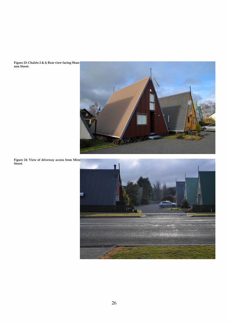
Figure 23: Chalets 2 & 4; Rear view facing Shan-non Street.
Figure 24: View of driveway access from Miro Street.

27
Figure 25: Elevation of Chalet 5. Note (obscured in image) skylight on eastern side of Chalet and deciduious tree in North-East corner of site.
Figure 26: Front elevation of Chalets 8, 9 & 10.
Note skylight on eastern side of Chalet 10. Note
adherence to 1970’s colour palette.

28
Figure 27: Chalet 5 corrugated iron roof with Chalet 8 at rear.
Figure 28: Chalet 9 elevation. Note period Conifer and A-Frame colour scheme.

29
Figure 29: Dining and Kitchen. Painted kitchen joinery and stainless steel benchtop.
Figure 30: Lounge and ladder (right). Note orig-inal ‘Visor’ fi replace.

30
Figure 31: First Floor Bedroom. Note window’s off centre location to align with front door below.
Figure 32: Ground Floor Bedroom. Conventional vertical wall to allow diff erent confi guration of space.

31

32Figure 33: Original Plans of Subject A-Frames

33
4. Case Studies4.1 ‘Trigon’, Switzerland
The demise of the American A-Frame, due to proliferation of ‘McMansions’ and the realisation of the limits of the form, necessitated the need for further in-situ redevelopment. The most dramatic example of this is the A-Frame designed for Heidi and Peter Wenger in Swi! erland, appropriately named ‘Trigon’. Built in 1955, Trigon is an alpine example of the type, typical in its construction. However, Trigon is able to be enclosed during uninhabited months through a suspended trian-gular gable end that, with the aid of a pulley and rope system, endow the structure with a deck.
The intervening twenty years saw the Wenger’s use of the chalet decline. Unlike the vast majority of own-ers however, the Wengers’ opted to sympathetically alter their A-Frame to adapt to their lifestyle whilst keeping the essence of the form intact. From an interior architectural perspective, this involved the removal of partition walls creating a uniform spatial experience. A basement was also created, and acts as an anchor by which the A-Frame se" les into its environment, where previously the connection with the ground was somewhat tenuous. The couple took the notion of bespoke to another plane by custom designing furniture and fi " ings to align the interior with their lifestyle. Of particular note is the circular kitchen unit that delineates the main living area and introduces a contrast to the traditionally angular interior.
Understanding the form and its potential, the Wenger’s replaced the standard rectangular joinery with triangular centrally pivoting units, embracing the A-Frame’s potential. It should be noted that the Wenger’s were architects, so the ability to visualise the evolution of their house was perhaps more easily realised than most. The opposite side of bespoke, though, is kitset.
And what was to become of that?
Figure 34: Trigon Chalet in Winter, deck extended. Date unknown.
Figure 35: Interior of Trigon Chalet. Note pivoting glazing.

34
4.2 David Hellyers Cabin #4
Hellyers Cabin represents the acme of collabora-tive marketing. The ‘Douglas Fir Plywood Association’ became aware of the project in 1957 (Randl), and off ered Hellyer a contra deal of building materials for exclusive use of his plans. It is of importance that the same year, Andrew Geller designed Be" y Reese’s House, so one can assume this was ‘the’ year of the American A-Frame.
While Geller went on to experience professional success, the Douglas Fir Plywood Association had orders for some 12000 sets of working drawings within a few months of the publication of the project. (Randl, Old House Journal). This is a similar phenomenon to the success of John Campbell’s ‘Leisure House’ some 6 years earlier.
As a means of understanding the construction technique and spatial complexities of the early Cabin, a 1:50 model was constructed. The purpose of this was to appreciate the interior spatial dynamic, indeed, a physi-cal representation of the structure allowed this beyond the limits of digital modelling.
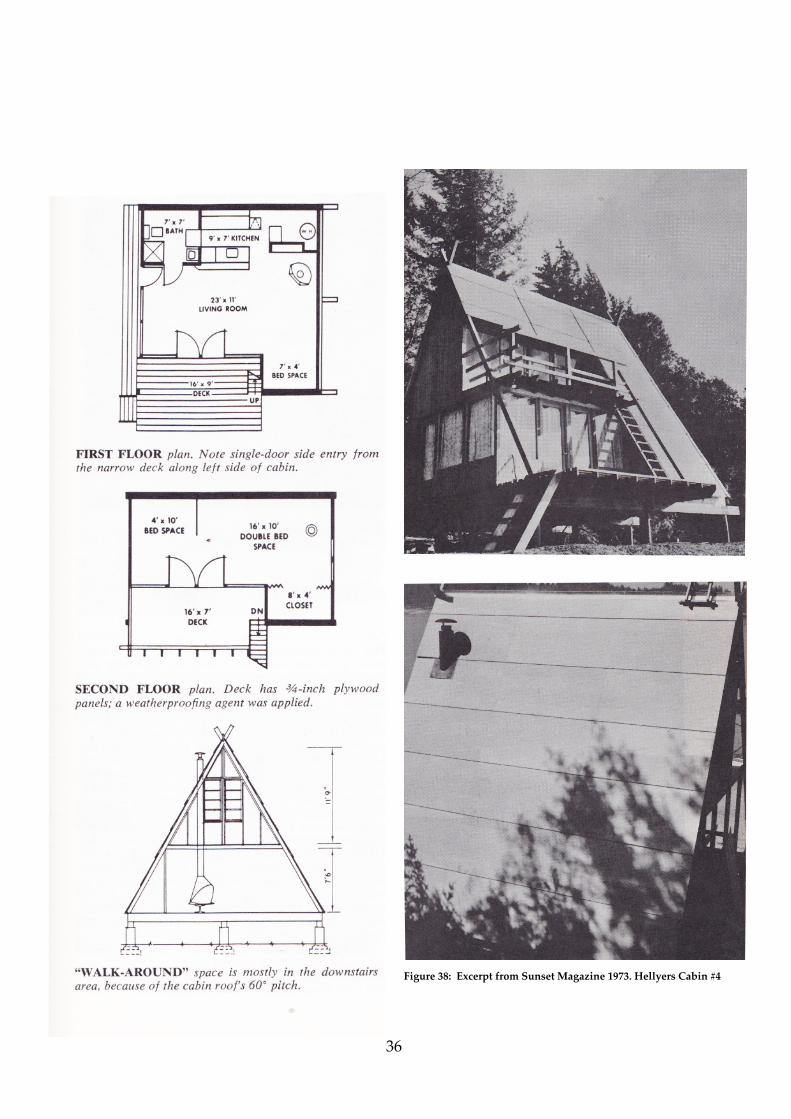
The physical model highlighted the limitations of the interior, in particular the ineffi ciencies of space. As access to the upper level sleeping area is permi" ed through an external ladder, we interpret this gesture as a nod to the cabins intended warm climate locale. How this translated to an alpine se" ing is questionable.
Of interest is the design of the roof system. Full size sheets of marine ply act as oversized roof shingles, an effi cient means of speedily enclosing the structure and providing a clever (if rudimentary) solution to weather tightness. Longevity of the system and appropriateness to the Alpine se" ing is unknown, though it is assumed that owners superseded the plywood system to suit their specifi c environments.
Figure 36: 1:50 model of Hellyer’s Cabin #4

35
Figure 37: 1:50 model of Hellyer’s Cabin #4
36
Figure 38: Excerpt from Sunset Magazine 1973. Hellyers Cabin #4

37
Figure 39: Front Elevation of model showing decks and rafter structure.
Figure 40: Side Elecation showing fi rst story window.

38
Figure 41: Rear elevation of model. Note plywood ‘shingles’.
Figure 42: Side Elevation showing door to side deck access.

39
Figure 43: Detailing of fi rst fl oor deck hand railing.
Figure 44: Front door with view through model.

40
Figure 46: Close up of plywood roof shingles.
Figure 45: Ground fl oor of interior with view toward front door.

41
The purpose of building a model of this early example of the A-Frame was to understand the construction technique and spatial complexities of the dwelling. The open-plan nature of the interior, though obvious in the plans, is realised in greater detail by physi-cal construction.
The relative simplicity of the structure is evident; again, by physically representing this the commercial appeal of the cabin becomes apparent. Interior partitions were omi! ed for clarity, thus the model focuses on the holistic interior experience. It is expected that owners were able to adapt the internal layout of spaces, therefore the interior of the model was treated as such.
This exercise was of value from a conventional and interior architectural point of view, in that one needs to understand how a structure is built before one can set about altering it. Rafters were designed to fi t a conventional (of the time) 8 ft by 4 ft plywood sheet, we see economical considerations beyond the inherent effi ciencies of the kitset A-Frame.
Where possible, the model was built as per the plans in Randl’s A-Frame, though assumptions were made where detail was not provided.

42
5. PhilosophicalStrategy5.1 Fred Sco� , On Altering Architecture.
Now the existing typology is understood, a philosophical stance has to be established as a means of asserting a personal position by which to revisit the A-Frame’s interior.
Fred Sco! ’s On Altering Architecture deals in depth with the issue of authenticity and alteration. Sco! argues that ‘restoration nearly always involves modernisation of servicing’ (Sco! 92) , thus the intent of authenticity is inherently fl awed. Spatially, he argues that the building is ’broken’ (Sco! 95) by the alteration process. Relocation of spaces and rearticulated circulation renders the architecture beyond repair.
Sco! ’s theory of ‘stripping back’ the host building to inform alteration is of signifi cance to this research. It is defi ned as a ‘process by which the designer acquires an understanding of the host building with which he or she is engaged’ (Sco! 108). Further to this, Sco! discusses the role of drawings in analysis as primary evidence, though does not consider them defi ni-tive; likening them to ‘how a piece of music is set down on paper prior to a performance’ (Sco! 113).
Authenticity then, extends beyond the physical fabric of architecture. the expression of self being the fi rst response to the interior. In the ‘Leisurama’ example, this notion is given further impetus by the inclusion of household items in the style of the architecture; authenticity on varying scales. The human scale associates with the intermediate, the intermediate again with the architectural envelope. One could iterate this notion ad infi nitum; the landscape and choice of shrubbery, often selected to fashion’s whim, adds a further layer of authenticity to the intervention.
It is at this point that one must take a holistic view if the intent and evaluate the interior subjectively. Technological advances dictate the interior. Obsolete materials are replaced by modern examples ‘in the style of’.. This lack of truth again raises the issue of the stance. The desire for authenticity risks appearing nostalgic, however, it is often this that adulterates the design to the point of parody.
What then of the A-Frame and modern reinter-pretation? Scale comes to the fore here. A set of period cutlery, for example, has a minor eff ect on the response to architecture. However, a vehicle (parked in the drive-way) of the same vintage of the house somehow elevates its architectural authenticity. There is almost a parallel between inhabiting the interior of the house and car respectively, the car represents the means by which arrives at the interior and pre-empts the experience. This level of kitsch reverence appeal to a nostalgic few; the ones willing to truly indulge in ‘time warp’ architecture and lifestyle.
However peculiar the notion, there is a certain appeal in revisiting a simpler time. Interior architecture can extend backwards as well as forwards. A completely genuine recreation of the past can be credible, however fundamentally unrealistic it may be.
43
Sco� succinctly highlights this point when discussing the patina of the aged versus the apparent newness of the restored. He analogises using the example of an elderly couple with an equally elderly vehicle, both protagonists showing the signs of their age. The pi� ed chrome and worn leather of the vehicle represented the true intent of the designer; apparently evoking a more genuine response than the faux newness of a restored vehicle (Sco� 177). This highlights the absence of truth in restoration. I would argue that it is the contradiction of modern and patina that reveals the authenticity of the interior.
The notion of reinterpretation must be consid-ered through the human scale. The interior, therefore, should respond in the outset at a minor scale; and build to encompass the greater building envelope. Sco� ’s philosophy, though valid, fails to address the requirements of modern users. One must ‘break’ the building to make it suitable for modern inhabitation. In the case of the A-Frame and its inherent spatial and thermal issues, there is li� le scope to improve the design without major spatial reconfi guration and mechanical ventilation apparatus. With this in mind, the redesign will be sympathetic to traditional materials to an aesthetic extent; but will introduce contemporary materials and fi � ings to address the limitations of the originals.

44
5.2 Chad Randl, A-Frame.
Architectural Historian Chad Randl’s ‘A-Frame’ exam-ines the prehistoric Japanese ‘triangle houses’, rise and decline in popularity of the American A-Frame holiday house and the typology’s infl uence on modern architecture. He identifi es the typology as a dwelling with a ‘low slung, steeply pitched roof’ with ‘no intervening interior walls’ (Randl 5).
The scope for reinterpretation of the style is addressed early in the text, stemming from the early Swedish vedskjul and aforementioned Japanese versions, culminating in the post-war American A-Frame that came to be the widely adopted version of the style.
Post war affl uence is identifi ed as the driver of the rise in popularity of the A-Frame; though it is also noted that the reclamation of ‘tens of thousands of miles’ of coastal land also contributed to the popularity of the holiday house per se. The persistence and evolving design by young architects keen on provocative design shifted the marginalized concept into the mainstream, and with the added benefi t of national media exposure, catapulted the style into the imagination of middle-class Americans.
Northern California is widely accepted as the locale for the heralding of the style. Its alpine extremes provided the se$ ing for the application of a versatile and iconic design typology. The triangular form was lauded for its excellent structural integrity and resist-ance to snow and wind loads. It should also be noted that California is also the birthplace of the popular ‘Sunset’ magazine, a lifestyle editorial that was among the fi rst to feature the A-Frame as the object of desire for the aspirational middle-class, the ‘apres-ski’ lifestyle aspects of the style being depicted as the utmost in good taste.
Randl, though generally extoling the virtues of the style, briefl y identifi es the fl aws in the design. A lack of natural light, limited and wasted space, and diffi culty heating and cooling the space are seen as the major drawbacks. This is of relevance to this thesis as these fundamental issues are of signifi cant importance considering the aim of the project is to re-interpret the chalet from an interior architecture perspective.

45
The evolution of the A-Frame from holiday home to commercial premises is largely generalised. Randl observes the somewhat practical application of the style amongst American ecclesial groups as the form of their churches. The most curious application though is the adoption of the format by hospitality venues off ering Scandinavian style fare to the weary traveler. Quite rightly, we see connections to the alpine aesthetic, however contrived this notion may be.
Randl summarises the demise of the A-Frame alluding to a public furor that dwindled in the realisation that the limitations of the design often resulted in less than adequate interior conditions.
On a domestic level, New Zealand has a long standing fascination with the concept of prefabrication. Mark Southcombe and Pamela Bell’s Kiwi Pre-fab - Co� age to cu� ing edge identifi es the previously mentioned McRaeway A-Frame as being amongst the earliest of kitset housing, though the defi nition of prefab in this case is in fact a kitset where the owner erects the house from a series of pieces (in this case pre-cut timber lengths) as opposed to components. Indeed, the ‘self-build’ kitset stands apart from the prefab as a separate entity, requiring a higher degree of construction skill and knowledge.

46
5.3 The ICOMOS Charter
The ICOMOS charter was established as a docu-ment by which to address any alteration, preservation or conservation of historically signifi cant buildings. The Charters intent is to provide a means of understanding cultural heritage values, thus underpinning any modifi cation that may be detrimental to the historical importance of a building or site.
In the case of the A-Frame redesign, I have opted to address the ‘reconstruction’ and ‘alteration’ sections of the charter. Reconstruction addresses the material aspects of the building, stipulating that replacement of material that is no longer available or viable.
With this in mind, I have chosen to reuse the existing rafters where possible and replicate the profi le, fi nish and species in the realised outcome. Materials not original to the subject A-Frame are selected based on the availability and profi le available in the early 1980’s, as a means of imbuing original character into the interior. It should be noted that the promotion of the social ‘standing’ of the interior aligns to the material choice i.e rudimentary plasterboard ceilings replaced with native timber tongue and groove appropriate to higher level architectural fi nishes of the era.
Alteration of the A-Frame when aligned to the ethos of the charter raises the issue of the degree of intervention and its eff ect on the historical signifi cance of the altered form. It states that:
‘Any alterations or additions should be compatible with the original form and fabric of the place, and should avoid inappropriate or incompatible contrasts of form, scale, mass, colour and material. Adaptation should not dominate or sub-stantially obscure the original form and fabric, and should not adversely aff ect the se� ing of a place of cultural heritage value. New work should complement the original form and fabric.’ (ICOMOS)
Consideration of the degree of intervention is crucial. Though the introduction of a non-original material is a potentially unfavourable gesture, in this case I believe it to compliment the original materials and set a hierarchy that reads as a textural pale# e. This act allows the materials to speak on a direct level, as was proposed by Brooker in ‘Re-readings’ that ‘for a successful dialogue to be established, the two components must be speaking equally loudly, albeit in diff erent languages’ (Brooker 102).
Here we see the composition of the materials working in a holistic manner, the scale and ratio of use dictating the degree by which they are understood. Placement also comes to the fore here, where concrete is used a means of grounding the structure. The longitudinal placement of the form suggests a structural intent, indeed as does the inherent character of the material.

47
6. Strategy6.1 ‘Insertion’ - Re-readings
The basis for the remodeling of the A-Frame relies upon ‘insertion’. The relationship between the intervention and the original building should be a counter-balance, ‘the two components speaking equally loudly, albeit in diff erent languages’. (Brooker 102)
This counter is achieved through contrasting material selection, the innate strength of concrete acting as the spine by which the A-Frame is supported. The transverse location of the concrete speaks of balance, equally underpinning both sides of the structure. A similar relationship can be seen in John Sco" ’s Futuna Chapel in Karori. The somewhat temporary (by comparison) nature of timber given impetus by the permanence of concrete, in Sco" ’s case a custom coloured ‘Firth’ breeze block and pebble-dashed surface treatment. A game of opposites sets the tone for an engaging and provocative interior, as in Futuna Chapel, colour and light is perceived diff erently depending on the surface on which it casts itself. Indeed, the lofty interior form lends itself to an almost ethereal atmosphere, exploited in both of the intimate bathroom spaces in the A-Frame by considered light permeation through acrylic apertures. Sco" ’s dramatic treatment of colour and light has infl u-enced aspects of the redesigned A-Frame’s interior.
The treatment of timber in the interior of the chapel, a relationship mimicked by Walker and Athfi eld (to name but a few) some decades later, suggests a dynamic interface. Structural components are stained black, supporting the naturally fi nished tongue and groove ceiling. Again, the notion of scale and hierarchy becomes apparent; concrete being the protagonist, black timber the secondary player and natu-ral timber acting as the darling of the interior ‘stage’.
Sco" ’s early sketches draw parallels between the ‘tent’ (European architecture) and Maori Whare. Alternating fl oor levels again reinforce ‘insertion’. Delineation of surfaces creates a spatial dialogue that identifi es the purpose of the space. The lower concrete fl oor surfaces integrate seamlessly with the vertical elements again acting as a means of integrating the insertion into the greater whole.
Figure 47: Early sketch of John Sco! ’s Futuan Chapel. Note triangular roof forms and glazed facades.

48
7. PreliminaryDesign7.1 Initial conceptual response
The initial studies responded to the lack of useable space of the triangular form. The shifting of pitch to provide a traditional vertical wall resulted in an iteration that evoked the original, yet provided a more conventional (for the most part) interior experience. It should be noted that the original concept was intended to be a thoroughly new interpretation of the A-Frame, not a redesign of an existing structure. This intuitive response was undertaken prior to establishing a philosophical stance.
Vertical window screens can be tilted to a hori-zontal position to provide shade to the space beneath. This concept borrows from the precedent set by Andrew Geller and his a brise soliel, though in this case acts in a semi –permanent manner allowing the structure to be rid of superfl uous appendages when not in use.
Although this iteration was an intuitive response to sunlight and spatial limitations, it aligned more closely with a conventional architectural project. As a means of aligning the research with interior architecture, I opted to redesign the interior of an existing chalet following the philosophy of Fred Sco" ’s ‘On Altering Architecture’ and Graeme Brooker and Sally Stone’s ‘Re-readings’.
Figure 48: Illustration of intuitive design. Figure 49: Developmental drawings.

49
The spatial limitations are clearly noticeable in the fi rst fl oor areas, with the uppermost space being suitable only for storage. The acute angle of the roof plane has, however, allowed a sense of spatial ‘loftiness’ that the original form lacks. Interconnectivity between the fl oors furthers this notion allowing a holistic experience of all spaces throughout the interior.
This initial response highlighted the need for consideration of solar control and the dynamic between vertical and inclined planes.
Figure 50: 1:50 model of initial design response.

50
Figure 51: Shades in closed position.
Figure 52: Shades in open position.

51
Figure 53: Shades partially open (alternative location)
Figure 54: Shades closed in alternative position.

52
7.2 Prefabfi cation
The basis for investigating prefabrication (hereafter ‘pre-fab’) was the kitset style off ered by Mcraeway homes in their A-Frame houses.
The concept was based around a rafter ‘rib cage’ into which pre-insulated and lined panels would be inserted. A fl at pack system of delivery would ensure an effi cient and cost eff ective means of construction.
Original sketches investigate a collapsible rafter system, though after development this proved to be logistically ineffi cient, involving pin joints that would compromises the integrity of the structure. It was supplanted by a kitset system (again similar to McRaes’ original) that could be erected by a person of limited building experience.
Figure 57: Insulated panels insitu
Figure 56: Panels and fold down deck
Standardisation of the panel size (i.e: 2400 x 600 mm) would allow effi cient use of material. Further to this, the option to used recycled timber pallets as the structural member of the panel introduced a sustainable means of cost and material reduction.
Figure 55: Conceptual drawings of ‘pre-fab’ design.

53
Figure 58: Detail Sketches of design.

54
Critical Assessment of Iteration
Although the design has potential as far as mass production and low-cost accommodation, the design steers away from the intent of the research “elevated from nostalgic novelty to spatially responsive contemporary architecture”.
The adaptability of the from is appealing and consistent with the purpose of the structure, however, it fails to address the greater question of elevating the form. This requires an additional level of consideration; the issues of spatial dynamics and detail are of importance, but in this case these are somewhat overshadowed by what could be considered ‘conventional’ architectural concerns. Needless to say, the structural feasibility and integrity are paramount in any project, though in this case the detailing of this aspect cannot be ‘assumed’, and therefore falls outside of what is primarily interior
architecture research.
What I did gain from this iteration was the benefi t of re-using an existing piece of material, be it a repurpose in the case of the pallet, or the retaining of existing materials in a structure. The philosophy of the ICOMOS Charter becomes important here, and will be the baseline for further iterations of the A-Frame.

55
7.3 The Shroud
This iteration deals with the adaptability of the form and its ability to regulate the amount of daylight permi! ed into the interior. The shroud system encapsulates the original form and moves on a rail and wheel system . Fold-out decks at either end allow the structure to be closed up when not in use, a similar mechanism to that employed by Trigon Chalet.
Further to this concept, the sliding shroud system mimics the traditional form of the A-Frame, yet adds a layer of aesthetic interest (and solar protection). Sheltered alfresco areas are created at either end of the structure with the shroud system engaged, responding to the need for such areas in the summer months.
Figure 59: Render of ‘Shroud’ extended. Figure 60: Render of ‘Shroud’ in Winter mode (top) and Summer mode (bo! om).

56
Figure 61: Sketch deatil of shroud system.
Figure 62: Sketch detail of shroud system.

57
Figure 64: Interior showing loft and bathroom enclosure.
Figure 63: Schematic of interior and fi xed deck.

58
Figure 65: Physical model of A-Frame with shroud in ‘Winter’ posi-tion.
Figure 66: Shroud extended to ‘Summer’ position.

59
Figure 67: Rear view of model demonstrating original form with shroud facing North.
Figure 68: Experiment with light through extended shroud.

60
Critical Assessment of Iteration
While the consideration of solar gain is crucial, the scope of the project is primarily interior based. The ‘shroud‘ system could be further investigated as a building science proposition, and be quantifi ed by thermal analysis.
With this in mind, I have opted to retain the shroud on the west side of the dwelling to negate solar gain from afternoon summer sun. This remains a rudimentary proposition that with further testing and development could be refi ned to add a further layer of solar control to the re-design of the A-Frame.
Figure 69: North Elevation with glazing inspired by Trigon Chalet.
61
8. Developed Design
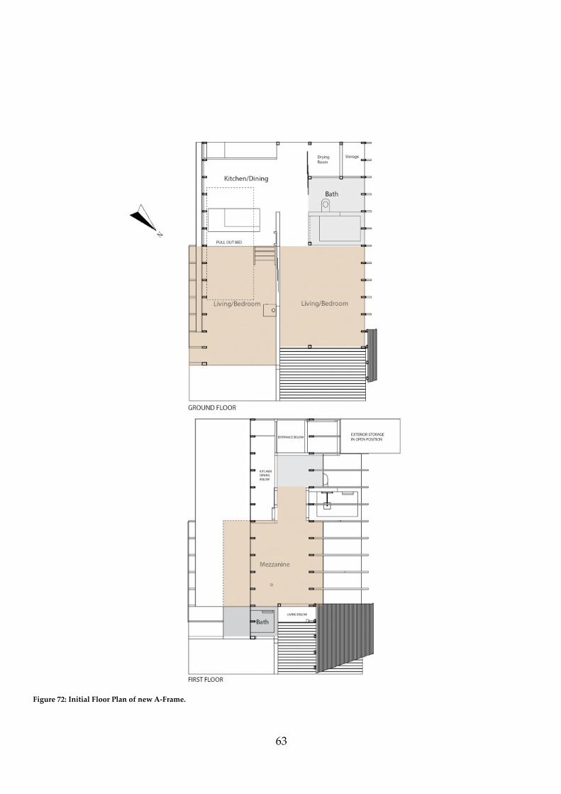
The ground fl oor of the A-Frame is comprised of kitchen/dining, drying room, bathroom and combined living/bedroom spaces. The adaptability of these spaces enables the interior to be suitably adapted to suit the number of occupants. The rationale behind this was to allow the architecture to respond to the occupants instead of compromising the experience of the inhabitants.
The drying room has been retained, but split to include external access storage space. The advantage of this is to provide a small area in which to store necessary implements for maintenance that is accessible without entering the dwelling.
Delineation of the fl oor plane allows spatial intimacy and a means of accommodating integrated furniture items. The contrast of materials between the two ground fl oor living/bedroom areas again alters the dynamic of the spaces, providing two diff erent interior experiences. The timber fl ooring of the western living area suggests a more intimate atmosphere compared to its more austere concrete counter-part.
The shroud system investigated earlier in the design process has been developed into a full height screen mounted on the west facade of the A-Frame. As previously, the screen is able to be moved to adjust to the season and the amount of sunlight required to enter the interior.
At this point of the project, it became evident that a brief needed to be established. Limitations of the project also had to be considered.
Project Brief:
Redesign the interior of the subject A-Frames to provide:
• Accommodation for 2-6 inhabitants• Consideration of thermal limitations• A pale! e of materials that align to a ‘high-end’ fi t out• The ability to spatially reconfi gure the interior to
suit the level of occupancy• Durability and sustainability of materials
Limitations in scope:
The project will consider, but not resolve:
• Buildability based on structure outside the scope of NZS3604
• Final build cost/budget• Measured thermal performance• The outcome will be largely conceptual

62
Figure 71: Longitudinal exploration of spaces.
Figure 70: Early developmental sketch of layout.
63
Figure 72: Initial Floor Plan of new A-Frame.

64
8.1 Materials and Technology
The original materials of the subject A-Frame are as one would expect in a relatively low budget dwelling. Gib board is primarily used as the ceiling and wall treatment, an obvious choice given its cost effi ciency and availability. The original kitchen joinery is painted composite with a stainless steel bench top.
Material selection is a crucial consideration for the re-design of the subject A-Frame. The intent is to “elevate the form from nostalgic novelty to spatially responsive contemporary architecture”. With this in mind, one has to avoid cliché application. Nostalgic hints must be realised through form and material, though it presents a formidable challenge to deftly apply this. For this reason, I have selected design cues present in the late 1970’s that were often applied to higher end architectural projects.
Furthermore, while the era was consuming the seemingly inexhaustible supplies of native timbers (indeed, previous decades had also been as inconsider-ate) I have opted for a sustainably grown representation of the original. Macrocarpa, an exotic softwood of the cypress species, is prevalently grown in New Zealand. Tongue and groove clears are to be laid horizontally throughout the interior as a ceiling treatment, fl oor and cabinetry facings. All existing rafters are to be retained and re-purposed where possible. All additional interior structural members are to be rough sawn to match, and stained black.
The issue of insulation is critical here. Clause H1 of the New Zealand Building Code requires that the ceiling cavities of dwellings in the central plateau area have an insulation value of R 3.5 (New Zealand Standards).
The kitchen drawer and cupboard fascia’s are again Macrocarpa, where necessary these are to be biscuit jointed and grain matched to provide a high level of fi n-ish to panels greater than 150mm width. Stainless Steel 25 x 25 mm square extrusion is to be used as the legs and frame of the units, in conjunction with Blum ‘Movento’ drawer runner systems.
Tiled surfaces of the bathrooms and kitchen are 1970’s inspired ‘Moss’ 150 x 73 mm supplied by Middle Earth Tiles and laid in traditional ‘brick’ pa$ ern.
Figure 73: Middle Earth Tiles ‘Moss’
Standard fi berglass insulation requires a cavity of 100mm in which to optimally perform. With this in mind, and considering the 200mm rafter into which the void will impinge, I have opted for a 75mm PIR (polyisocyanurate) insulation panel supplied by Christchurch based Conquerer PIR Panel. These panels have a R 3.6 rating, and will permit a 105mm rebate of the existing rafter to be visible once the 20 mm Macrocarpa sarking is installed.

65
Figure 74: Materials (clockwise from left), black stained Macrocarpa, polished Concrete, 25 x 25 mm Stainless Steel extrusion, 6 mm Decor Satin Acrylic, Tongue & Groove Macrocarpa.

66
8.2 The Core
The introduction of concrete into the interior of the A-Frame acts metaphorically as an anchor, a similar notion to the schist basement of the Trigon Chalet case study. The intent is to imbue the interior with a sense of perma-nence; yet integrate existing timber structure.
As in John Sco! s’ Futuna Chapel, the dialogue between the materials should be interpreted as a conversation, a complimentary relationship that underpins the understanding of the interior. The innate strength of the material has enabled the mezzanine bathroom to be suspended off the vertical member, thus creating spatial intimacies in the living/bedroom below and and unbridled view to Mount Ruapehu from the fi rst fl oor bedroom.
Consistency of form is achieved through a uniform surface treatment, in this vertical members will be poured within rough sawn form work, fl oors will be polished. Vertical members will either be cast on site, or constructed off -site and erected in a ‘tilt-slab’ manner. Interiors of the bathroom spaces will be waterproofed and tiled.
Figure 75: Core shown with exposed building envelope.

67
Figure 76
Figure 77

68
Figure 78
Figure 79

69
Figure 80
Figure 81

70
8.3 Kitchen & Furniture
In accordance with the ethos adopted for the redesign of the A-Frame, the kitchen utilises an ‘honest’ material and system selection. The ‘Good Bones’ kitchen cabinetry system was chosen primarily for its adaptability and integrity of design. The absence of manufactured timber products (eg: particle board) allows the confi guration of the kitchen to be altered should the need arise. In addition, cabinet facings can be easily replaced.
The ‘Good Bones’ system was developed by Christina Mackay as a reaction to the unsustainability of traditional ‘carcass’ MDF cabinet construction (Good Bones). The inherent durability and ecological conscience of the system is of relevance to this project, as the intended purpose of the interior indicates a high level of use by varied occupancies.
The system is based upon a metal frame that replaces the traditional carcass. It is able to be kitset as-sembled and off ers a high level of customisation. The aforementioned steel members allow infi nite options of confi guration, again appealing to the unconventional interior form of the A-Frame.
Figure 82: Early developmental model of Kitchen.
Figure 83: Exploration of possible ceiling treatment for Kitchen.
71
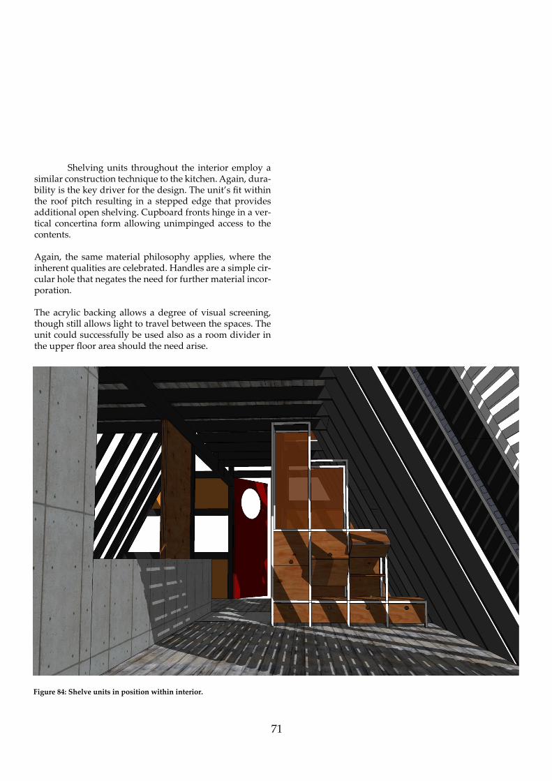
Shelving units throughout the interior employ a similar construction technique to the kitchen. Again, dura-bility is the key driver for the design. The unit’s fi t within the roof pitch resulting in a stepped edge that provides additional open shelving. Cupboard fronts hinge in a ver-tical concertina form allowing unimpinged access to the contents.
Again, the same material philosophy applies, where the inherent qualities are celebrated. Handles are a simple cir-cular hole that negates the need for further material incor-poration.
The acrylic backing allows a degree of visual screening, though still allows light to travel between the spaces. The unit could successfully be used also as a room divider in the upper fl oor area should the need arise.
Figure 84: Shelve units in position within interior.

72
Figure 85: Sofa (Top), folded out to bed (bo� om).
The furniture designed for the Bedroom/Living spaces responds in the same way as the architecture - adaptable depending upon use. Constructed of 25 x 25 mm Stainless Steel extrusion, the piece acts as a sofa with storage under, when unfolded becomes a conventional Queen sized ma! ress.
Of note is the angled rear of the armrest that allows the top half to pivot within the 60 degree slope of the interior without the need to move the unit to provide clearance. The units can be positioned throughout the in-terior, and will function whether against the sloping wall, or the vertical concrete wall.

73
Bathrooms and Showers
The bathroom areas of the interior are designed beyond their utilitarian purpose and elevated to spaces of ceremo-nial refuge. The ground fl oor shower takes advantage of the elevated celing space, eff ectively becoming a light well. The use of satin acrylic diff uses the light throughout the shaft countering with the handmade ‘Middle Earth’ tiles in the shower.
By dropping the shower cubicles below the fl oor levels the occupant is given the sense of separation from the planar levels. This ‘shift’ again emphasises the sense of refuge.
Figure 86: Developmental model of lower Bathroom.
Figure 87: Developmental model of Upper Bathroom.

7474
Figure 88: Core system showing upper level bathroom recess abu� ing vertical member
Figure 89: Lower bathroom recess with drying room in foreground.

75
Figure 90: Longitudinal exploded view of interior
Exposed west side of the A-Frame, showing ground level bathroom, sun shade and storage locker. Of note is the connection of the concrete transverse member to the aforementioned bathroom and its integra-tion of the interior components.

76
Figure 91: South view of Interior
Note pull out bed beneath kitchen at left of image. This was later su-perseded by a free-standing alternative to allow spatial re-confi gura-tion to suit the type of occupation. Informal dining bench is visible
above.

77
Figure 92: North view towards Mount Ruapehu
Developed concept of lower living areas. Ladder to loft is visible left of centre. Note ‘Pyroclassic’ Woodburner has subsequently been replaced by integrated concrete unit within core.

78
Figure 93: Light shaft - Lower Bathroom
View from lower bathroom shower through to fi rst fl oor of interior. Note skylight permits light into shaft, and again into interior through satin acrylic panels.

79
Figure 94: Illustration of redesigned A-Frame, North Elevation.

80
This page intentionally left blank.

81

82
Figure 95: Redesigned A-Frame in context.

83
9. Project Documentation
6 mm Decor Satin Acrylic Sheet.
Glazing, double glazed Alumini-um frame supplied by Nu-Look
140 x 75mm Middle Earth Tile in ‘Moss’
75mm Tongue and Groove dressed Macrocarpa (Applicable on ceilings) On decks, 75 x 25 mm Macrocarpa with 5mm gap.
Concrete.
MATERIALS LEGEND
10 mm plywood veneer.
Lacquered enamel paint fi nish.
Rough sawn interior timber, black stain.
84
DOWN
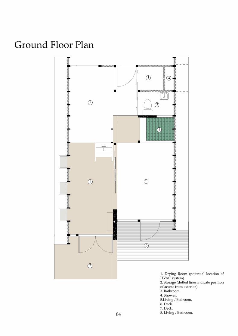
Ground Floor Plan
1 2
3
4
5
6
7
8
9
1. Drying Room (potential location of HVAC system).2. Storage (do! ed lines indicate position of access from exterior).3. Bathroom.4. Shower.5.Living / Bedroom.6. Deck.7. Deck.8. Living / Bedroom.

85
First Floor Plan
1
2
3
4
1. Storage.2. Bathroom.3. Mezzanine Bedroom.4. Shower.

86
Interior Elevation North
2
1
3
1. 6.0 mm PSP Decor Satin Orange Perspex.2. 150 x 73 ‘Middle Earth’ tile.3. Concrete fi rebox with be-spoke 5.0 mm mild steel liner and S/S fl ue.
50 x 50 mm square M/S extrusion.
40 x 40 mm Macro-carpa slats affi xed with S/S screw to steel frame.

87
Interior Elevation South
1 3 42
1. Kitchen (Units omi! ed for clarity)2. Front Door.3. Drying Room.4. Storage.

Le
ve
l 2
3511
23
56
47
1.
Up
per
B
ath
roo
m
(Ob
-sc
ure
d).
2. S
lid
ing
do
ors
to
lo
wer
ser
-v
ice
area
s.3.
Sli
din
g d
oo
rs.
4. L
ivin
g /
Bed
roo
m.
8
Level 1 0
Level 2
2984
2
3
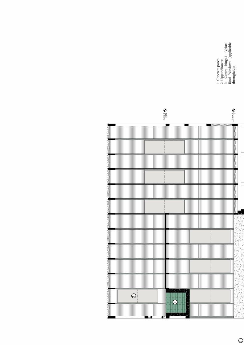
1
1. C
on
cret
e p
orc
h.
2. U
pp
er S
ho
wer
.3.
C
entr
e h
ing
ed
‘Vel
ux
’ R
oo
f W
ind
ow
s (a
pp
lica
ble
th
rou
gh
ou
t).

90
Ground Floor Bathroom Plan

91
Ground Floor Bathroom East
92
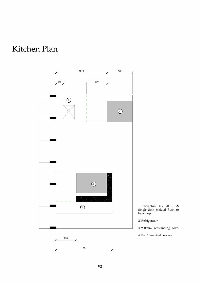
1662
595
1510
600
760
215
1
2
3
4 1. ‘Brighton’ DV 203L S/S Single Sink welded fl ush to benchtop.
2. Refrigerator.
3. 900 mm Freestanding Stove.
4. Bar / Breakfast Servery.
Kitchen Plan

93
Kitchen Elevation South & Runner Detail
2
Level 1
0
Level 2
2810
1
1. ‘Brighton’ Stainless Steel Sink.2. Refrigerator.3. 6mm Decor Satin acrylic screen.
3
Typical drawer runner detail based on Blum ‘Movento’ system.

94
2
2
Level 1
0
Level 2
2810
Kitchen Elevation West
95
Level 1
0
Level 2
2810
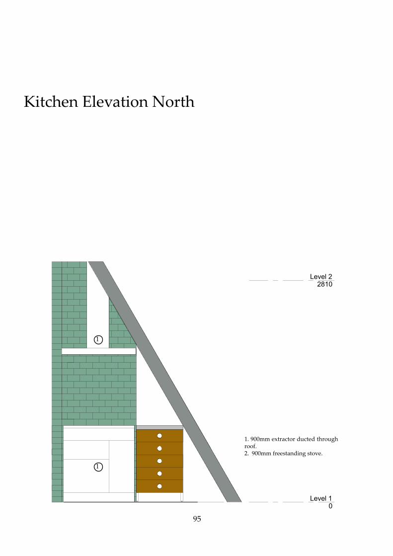
Kitchen Elevation North
1
1
1. 900mm extractor ducted through roof.2. 900mm freestanding stove.

96
10. Design Conclusion
The intent of this research was to redesign an existing A-Frame to ‘elevate the form from nostalgic novelty to spatially responsive contemporary architecture’. By applying the philosophy of Fred Sco! and fundamentals of the ICOMOS Charter, the design outcome of the research succeeds on a number of levels.
The refi nement and reapplication of existing materials, coupled with the introduction of complimentary materials, has imbued the interior of the A-Frame with a level of sophistication not apparent in the original. Consideration of thermal and spatial concerns, a major issue in the original, has been negated through the incorporation of effi cient furniture systems, modern insulation technology and adaptable spaces based on the type and volume of occupancy.
Inherent nostalgic aesthetic has been maintained however, by retaining the original form and utilising new materials in the ‘style’ of the original. Where possible, material selection has been considered from a sustainable perspective. The pale! e and detail draws from a late 1970’s aesthetic, though avoids appearing sentimental by means of utilising the materials with a contemporary bent; the fi ne balance of durability and elegance.
Spatially, the re-designed A-Frame responds to the brief by being adaptive and responsive. Its varied zones provide for diff erent types of occupation; be it a weekend getaway for a couple or an extended stay by a larger group.
The inclusion of concrete as a secondary material eff ectively underpins the interior experience by introduc-ing hierarchy and order. The placement of the element is fundamental to its success. The longitudinal central axis implies a structural purpose, though it is only by acting as a means of suspending the upper level shower that this is the case. By delineating the interior into two halves it automatically allows the spaces to be as separate orintegrated as is required. The concrete also acts as a primary source of thermal mass, addressing the needs of seasonal inhabitation.
Again, the shift in levels of fl oor according to material adds to the notion of hierarchy and spatial interest. The lower concrete lounge / bedroom implies a shift; one could surmise the weight of the concrete has pulled away from the wooden fl oor level fi nding its own equilibrium as true ground level. Connection with the ground in this area furthers the sense of intimacy; the concrete extending beyond the interior and reaching towards Mount Ruapehu.

97
10.1 Critial Review
As set out in the brief, the outcome can comfort-ably accommodate up to six occupants. The design stays true to the playful nature of the original. Room adjacencies are challenged, resulting in a dynamic and unexpected in-terior experience. The adaptability of spaces allows each sleeping area to be isolated in the event of full inhabita-tion, conversely, the spaces can revert to their alternative use when required.
Thermal concerns are addressed by utilising mod-ern insulation materials, a concrete core thermal mass, so-lar screen and modern glazing units. There is provision for a HVAC system to be installed in the ceiling cavity of the drying room that could be ducted throughout the structure.
Materials are kept to a refi ned pale" e of timber, concrete, tile and acrylic screen. These loosely adhere to a 1970’s inspired colour scheme. The realisation that the A-Frame could be rented for a percentage of the year in-formed the choice for durable materials.
The limitations of the scope allowed for carte blanche in relation to budget. This allowed the design to evolve without restraint. Again, engineering of the con-crete member was not considered as part of this research.
The research successfully elevates the form from nostalgic novelty to spatially responsive contemporary
architecture.

98
10.2 Thesis Conclusion
When one is gauging the success of a piece of research they must consider the impact on the subject, what has gone before their research and what potential benefi t there is in their work. With this in mind, I hope that this research acts not as a design guide for the renovation of an A-Frame, but as a means of undertak-ing any sort of design project that deals with altering any existing structure.
The historical review of the typology in New Zealand is of value to future researchers, particularly as a contribution to understanding the relationship between societal changes and architecture.
While the project goes beyond mere ‘renovation’, the philosophies threaded are perhaps as pertinent now more than ever. To me, truth in material is paramount. Le� ing the material express it’s natural qualities automatically elevates an interior. Dialogues become relationships.
As far as process, it was a somewhat optimistic expectation to fully resolve every detail of the interior and building envelope. Where applicable, assumptions have been made based on rudimentary known solutions. At times such considerations extended beyond the scope of the research, which is primarily interior architecture.
I was drawn to the research because of the limited resource information available. A number of A-Frame plans were collected and and analysed, the scope of variations and quality was unexpected. While most were basic in their design, many, including the subjects, a� empted to push the limits of the envelope and off er a more considered interior experience.
Though the research hasn’t set out to catagorise every example of the A-Frame in New Zealand, it has at least started the conversation and opened the door for future researchers. At the very least, the research demonstrates the beauty in sympathetic renovation using the A-Frame as merely one example of the many architectural curiosities in New Zealand.
Callan Svendsen, April 2016.

99
11. References
Betsky, Aaron. “Furnishing the primitive hut.” Weinthal, Lois. Towards a New Interior; An Anthology of Interior Design Theory. New York: Princeton Ar chitectural Press, 2011. p. 202.
Beaven, Peter. “Architecture Now.” March 2012. The New Romantics. 12 January 2016 <h! p://architecture now.co.nz/articles/the-new-romantics/>.
Brooker, Graeme and Sally Stone. Rereadings; Interior Ar chitecture and the design principles of remodel ling existing buildings. London: RIBA Enterprises Ltd., 2004.
Department of Building and Housing. Clause H1 Energy Effi ency. Wellington: New Zealand Government, 2011.
Gatley, Julia. Athfi eld Architects. Auckland: Auckland University Press, 2012.
Gordon, Alastair. Beach Houses Andrew Geller. New York: Princeton Architectural Press, 2003. —. Weekend Utopia; Modern Living in the Hamp tons. New York: Princeton Architectural Press, 2001.
Good Bones. “Design Features”. 23 March 2016. <h! p:// www.goodboneskitchens.co.nz/design-features/>
Harris, Cyril. Historic Architecture Sourcebook. New York: Von Hoff man Press, 1977.
Iacocca, Lee. An Autobiography. New York: Bantam Books, 1984.
ICOMOS, New Zealand. ICOMOS New Zealand Charter for the Conservation of Places of Cultural Herita ge Value. Auckland, 1993.
Isaacs, Nigel. “Thermal Insulation required in NZ Homes.” 23 February 2016. New Zealand History. 23 March 2016 <h! p:// www.nzhistory.net.nz/page/thermal-insulation- required-nz-homes>.
Jaehn, Tomas. “Stanford University Libraries.” n.d. Stan ford University. 3 May 2015 <h! p://web.stanford. edu/dept/SUL/library/sunset-magazine/html>.
Melling, Gerald. Positively Architecture; New Zealand’s Roger Walker. Dunedin: Square One Press, 1985
Mobbs, Michael. Sustainable House. New South Wales: Choice Books, 1988
New Zealand Tourism. “Ruaehu Skiing” Undated. Ac cessed 23 February 2016. <http:// www.tourism. net.nz/region/ruapehu/a! ractions-and-activities/ skiing-and-snowboarding>.
Ohakune Mountain Road. December 2012. 12 January 2016 <h! p://www.ohakune.info/ohakune-moun tain-road.html>.
Po! on, Craig. Tongariro - A Sacred Gift. Auckland: Lans
downe Press, 1987.
Randl, Chad. A-Frame. New York: Princeton Architectur al Press, 2004.

100
Randl, Chad. “The Mania for A-Frames.” July 2004. Old House Journal. 15 August 2015 <h� p://www.old housejournal.com/magazine/2004/july/aframes. shtml>.
Sahre, Paul. Leisurama Now - The Beach House for Everyone 1964-. New York: Princeton Architectural Press, 2008.
Schneiderman, Deborah. Inside Prefab. New York: Prince ton Architectural Press, 2012.
Scot, Fred. On Altering Architecture. New York: Rout ledge, 2008.
Statistics New Zealand.“Subnational Population Esti mates: At 30 June 2015 (provisional)”. Retrieved 12 November 2015.
Southcombe, Mark and Pamela Bell. Kiwi Pre-Fab - Cot tage to Cu� ing Edge. Auckland: Bala soglou Books, 2012.
Toffl er, Alvin. Future Shock. London: The Bodley Head Ltd., 1970.
Toolan, Brian. “The A-Frame House Plan; Revisiting a 50’s Sensation.” 7 February 2013. The Plan Collection. 12 January 2016 <h� p://www. theplancollection.com/house-plan-relat ed-articles/the-a-frame- house- plan-revisiting-a-50s-sensation>.
Wilhide, Elizabeth. ECO; An essential sourcebook for environmentally friendly design and decoration. London: Quadrille Publishing Ltd, 2002.

101
11.1 Image Sources.
1: Svendsen, Callan. “Early Sketch of A-Frame.” 2015. JPEG.
2: Early Scandinavian Tents. Photograph. n.d. Shifting Boundaries. Web. 20 January 2016. < h! p://www.chebucto.ns.ca/Culture/Shifting_Bounda-ries/tents1.html>
3: Melling, Gerald. “Johnson House.” 1984. Photograph. Positively Archi-tecture. Dunedin, Square One Press. 1984. P 43. Print.
4: Melling, Gerald. “Wellington Club” 1984. Photograph. Positively Archi-tecture. Dunedin, Square One Press. 1984. P 25. Print.
5: Bennati A-Frame Plans. Photograph. 1936. NC Modernist. Web. 15 May 2015.
6: Be! y Reese House. Photograph. n.d. Andrew Geller - Architect of Happi-ness. Web. 26 June 2015.
7: Leisurama Artist’s Impression. JPEG. n.d. Andrew Geller. Web. 15 Au-gust 2015. < h! p://www.andrewgeller.net/commercial/leisurama.html>
8: Leisurama Advertising. JPEG. n.d. Curbed Hamptons. Web. 15 August 2015. <h! p://hamptons.curbed.com/2015/4/29/9965836/leisurama-ma-cys-montauk-vacation-homes-for-the-middle-class>
9: Svendsen, Callan. “McRaeway Matchbox.” 2015. Photo.
10: McRaeway Pioneer Series. 1985. Mcraeway Homes. Timaru. May 2015. JPEG
11: McRaeway A-Frame. Photograph. n.d. McRaeway Homes. Web. 2 May 2015. < h! p://mcraewayhomes.co.nz/history/>
12: Svendsen, Callan. “McRaeway Show Home.” 2015. Photo.
13: Svendsen, Callan. “McRaeway Cu! ing Schedule.” 2015. JPEG
14: “Practical Planning” 1973. Illustration. Cabins and Vacation Houses. Menlo Park, Lane Books. 1973. P 108. Print.
15: “Cabins and Vacation Houses” 1973. Photograph. Cabins and Vacation Houses. Menlo Park, Lane Books. 1973. Cover. Print.
16: Svendsen, Callan. “Sunset Style A-Frame” 2015. JPEG.
17: Svendsen, Callan. “Mount Ruapehu at Dusk” 2015. JPEG.
18: Po! on, Craig. “Ski Fileds of Ruapehu.” 1987. Illustration. Tongariro - A Sacred Gift. Auckland, Lansdown Press. 1987. Print.
19: Satellite view of Subject A-Frames. “Ohakune, Ruapehu.” Map. Goog-le Maps. Google. 2 March 2016.
20: “Site Plan of Proposed Chalets”. 1985. Drawing. Ruapehu District Council. PDF. 24 June 2015.
21: Svendsen, Callan. “Chalet with Dormer” 2015. Photo.
22: Svendsen, Callan. “Chalets 8 & 9” 2015. Photo.
23: Svendsen, Callan. “Chalets 2 & 4” 2015. Photo.
24: Svendsen, Callan. “Miro Street access” 2015. Photo.
25: Svendsen, Callan. “Elevation of Chalet 5” 2015. Photo.
26: Svendsen, Callan. “Elevation of Chalets 8, 9 &10” 2015. Photo.
27: Svendsen, Callan. “Chalet 5” 2015. Photo.
28: Svendsen, Callan. “Chalet 9” 2015. Photo.
29: Dining Room and Kitchen. Photograph. n.d. Book-A-Bach. Web. 18 February 2016. < h! ps://www.bookabach.co.nz/baches-and-holiday-homes/view/31432 >
30: Lounge. Photograph. n.d. Book-A-Bach. Web. 18 February 2016.
31: First Floor Bedroom. Photograph. n.d. Book-A-Bach. Web. 18 Febru-ary 2016.
32: Ground Floor Bedroom. Photograph. n.d. Book-A-Bach. Web. 18 Feb-ruary 2016.
33: “Proposed Chalets Ohakune”. 1985. Drawing. Ruapehu District Council. PDF. 24 June 2015.
34: Trigon Chalet in Winter. Photograph. n.d. 37 E 7th St. Web. 12 April 2015.<h! p://blog.papress.com/post/70194835907/images-of-heidi-and-peter-wengers-1955-trigon>
35: Interior of Trigon Chalet. Photograph. n.d. All Good. 10 March 2016. < h! p://allgxxd.com/blogs/news/74791875-1955-trigon-chalet>
36: Svendsen, Callan. “Hellyers Cabin Model 1:50” 2015. Photo.
37: Svendsen, Callan. “Hellyers Cabin Model 1:50” 2015. Photo.
38: “This A-Frame is a doulbe decker” 1973. Photograph. Cabins and Va-cation Houses. Menlo Park, Lane Books. 1973. P 68. Print.
39: Svendsen, Callan. “Hellyers Cabin Model 1:50” 2015. Photo.
40: Svendsen, Callan. “Hellyers Cabin Model 1:50” 2015. Photo.
41: Svendsen, Callan. “Hellyers Cabin Model 1:50” 2015. Photo.
42: Svendsen, Callan. “Hellyers Cabin Model 1:50” 2015. Photo.
43: Svendsen, Callan. “Hellyers Cabin Model 1:50” 2015. Photo.

102
72: Svendsen, Callan. “Initial Floor Plan” 2015. JPEG.
73: Middle Earth Tile ‘Moss’. Photograph. n.d. Middle Earth Tiles. Web. 19 December 2015. < h! p://glaze.middleearthtiles.co.nz/greens.html>
74: Svendsen, Callan. “Material Pale! e”2016. JPEG.
75: Svendsen, Callan. “Core within building ” 2015. JPEG.
76: Svendsen, Callan. “Core.” 2015. Photo.
77: Svendsen, Callan. “Core.” 2015. Photo.
78: Svendsen, Callan. “Core.” 2015. Photo.
79: Svendsen, Callan. “Core.” 2015. Photo.
80: Svendsen, Callan. “Core.” 2015. Photo.
81: Svendsen, Callan. “Core.” 2015. Photo.
82: Svendsen, Callan. “Development of Kitchen.”2015. JPEG.
83: Svendsen, Callan. “Exploration of Ceiling Treatment.”2015. JPEG.
84: Svendsen, Callan. “Shelving Units.”2015. JPEG.
85: Svendsen, Callan. “Sofa/Bed Design.”2015. JPEG.
86: Svendsen, Callan. “Development of Lower Bathroom”2015. JPEG.
87: Svendsen, Callan. “Development of Upper Bathroom”2015. JPEG.
88: Svendsen, Callan. “Core System.”2015. JPEG.
89: Svendsen, Callan. “Lower Bathroom recess.”2015. JPEG.
90: Svendsen, Callan. “Longitudinal Interior.”2015. JPEG.
91: Svendsen, Callan. “South View of Interior.”2015. JPEG.
92: Svendsen, Callan. “North View of Interior.”2015. JPEG.
93: Svendsen, Callan. “Light Shaft.”2015. JPEG.
94: Svendsen, Callan. “Illustration of A-Frame.”2015. JPEG.
95: Svendsen, Callan. “A-Frame in Context.”2015. JPEG.
44: Svendsen, Callan. “Hellyers Cabin Model 1:50” 2015. Photo.
45: Svendsen, Callan. “Hellyers Cabin Model 1:50” 2015. Photo.
46: Svendsen, Callan. “Hellyers Cabin Model 1:50” 2015. Photo.
47: Futuna Chapel Sketch. Photograph. n.d. Teara - Futuna Chapel Wellington. Web. 12 January 2016. < h! p://www.teara.govt.nz/en/art-work/45753/futuna-chapel-wellington>
48: Svendsen, Callan. “Illustration of A-Frame.”2015. JPEG.
49: Svendsen, Callan. “Development Drawings.”2015. JPEG.
50: Svendsen, Callan. “1:50 Model.”2015. Photo.
51: Svendsen, Callan. “1:50 Model.”2015. Photo.
52: Svendsen, Callan. “1:50 Model.”2015. Photo.
53: Svendsen, Callan. “1:50 Model.”2015. Photo.
54: Svendsen, Callan. “1:50 Model.”2015. Photo.
55: Svendsen, Callan. “Conceptual pre-fab design.”2015. JPEG.
56: Svendsen, Callan. “Panels and fold-down deck.”2015. JPEG.
57: Svendsen, Callan. “Panels insitu.”2015. JPEG.
58: Svendsen, Callan. “Detail sketches.”2015. JPEG.
59: Svendsen, Callan. “Render of shroud extended.”2015. JPEG.
60: Svendsen, Callan. “Alternative shroud positions.”2015. JPEG.
61: Svendsen, Callan. “Sketch of shroud system.”2015. JPEG.
62: Svendsen, Callan. “Sketch detail of shroud system.”2015. JPEG.
63: Svendsen, Callan. “Schematic of interior and fi xed deck.”2015. JPEG.64: Svendsen, Callan. “Interior of A-Frame.”2015. JPEG.
65: Svendsen, Callan. “Shroud in Winter Position” 2015. Photo.
66: Svendsen, Callan. “Shroud in Summer Position” 2015. Photo.
67: Svendsen, Callan. “Rear View” 2015. Photo.
68: Svendsen, Callan. “Light Experiment” 2015. Photo.
69: Svendsen, Callan. “North Elevation” 2015. Photo.
70: Svendsen, Callan. “Early developmental layout sketch” 2015. JPEG.
Copyright © 2022 FDOKUMEN