Thermodynamic approach to enhanced dispersion and physical properties in a carbon...
8
Thermodynamic approach to enhanced dispersion and physical properties in a carbon nanotube/polypeptide nanocomposite Conrad S. Lovell a, b , Kristopher E. Wise b, c , Jae-Woo Kim b , Peter T. Lillehei c , Joycelyn S. Harrison c , Cheol Park b, d, * a Department of Materials Science and Engineering, University of Virginia, Charlottesville, VA 22904, United States b National Institute of Aerospace,100 Exploration Way, Hampton, VA 23666, United States c Advanced Materials and Processing Branch, NASA Langley Research Center, 6 W. Taylor Street, Hampton, VA 23681, United States d Department of Mechanical and Aerospace Engineering, University of Virginia, Charlottesville, VA 22904, United States article info Article history: Received 24 November 2008 Received in revised form 6 February 2009 Accepted 10 February 2009 Available online 21 February 2009 Keywords: Copolypeptide Single wall carbon nanotube (SWCNT) Nanotube/polymer interactions abstract A high molecular weight synthetic polypeptide has been designed which exhibits favorable interactions with single wall carbon nanotubes (SWCNTs). The enthalpic and entropic penalties of mixing between these two molecules are reduced due to the polypeptide’s aromatic sidechains and helical secondary structure, respectively. These enhanced interactions result in a well dispersed SWCNT/Poly (L-Leucine- ran-L-Phenylalanine) nanocomposite with enhanced mechanical and electrical properties using only shear mixing and sonication. At 0.5 wt% loading of SWCNT filler, the nanocomposite exhibits simulta- neous increases in the Young’s modulus, failure strain, and toughness of 8%,120%, and 144%, respectively. At 1 kHz, the same nanotube loading level also enhances the dielectric constant from 2.95 to 22.81, while increasing the conductivity by four orders of magnitude. Ó 2009 Elsevier Ltd. All rights reserved. 1. Introduction Next generation aerospace applications will demand strong and lightweight materials that offer additional intrinsic functionalities such as electrical conductivity, sensing, and actuation. Incorpora- tion of single wall carbon nanotubes (SWCNTs) into certain high performance polymers yields a lightweight material with dramat- ically improved mechanical and electrical properties that also exhibits sensing and actuating behavior [1,2]. Achieving these improved properties depends on the SWCNTs being well dispersed and stable with respect to reaggregation. Current nanocomposite fabrication techniques include melt mixing [3–5] and in-situ polymerization [1]. The large size and mass of the dispersed nanotubes and low mobility of the matrix polymer result in kinetic barriers that effectively prevent reaggregation over timescales relevant to most applications, provided the nanocomposite is not subjected to any significant thermal or mechanical perturbations. This caveat may make these kinetically trapped and metastable, but ultimately nonequilibrium, nanocomposites unsuitable for aero- space applications in which temperature excursions, cyclic mechanical loadings, and vibration are unavoidable. Thermodynamic stability of nanocomposites is governed by the free energy difference between the aggregated state and the dispersed (either individually or small bundles) state. The free energy change that occurs during mixing is composed of enthalpic and entropic contributions, DG ¼ DH TDS. If the free energy difference is negative or nearly zero, the dispersed state will be stable. Consider, for example, the case of large, rod-like fillers dispersed in a typical matrix composed of flexible or semiflexible polymer. In the absence of any countervailing enthalpic stabilizing interactions, entropic depletion interactions [6–8] will tend to drive the system to demix into coexisting rod-rich and polymer-rich phases [9]. We seek to ameliorate this entropic incompatibility by designing a polymer that is similar in diameter and flexibility to SWCNTs, specifically a polypeptide of amino acid monomers that promote an a-helical secondary structure. Achieving a negative enthalpy change upon mixing, without resorting to covalent modification of the SWCNTs, requires either destabilization of the aggregated state or augmentation of the SWCNT–matrix interaction. Mechanisms for aggregate destabili- zation include Coulombic repulsion, as might result from SWCNT reduction using alkali metal salts [10], and steric repulsion, * Corresponding author at: National Institute of Aerospace, 100 Exploration Way, Hampton, VA 23666, United States. Tel.: þ1 757 864 8360; fax: þ1 757 864 8312. E-mail address: [email protected] (C. Park). Contents lists available at ScienceDirect Polymer journal homepage: www.elsevier.com/locate/polymer 0032-3861/$ – see front matter Ó 2009 Elsevier Ltd. All rights reserved. doi:10.1016/j.polymer.2009.02.016 Polymer 50 (2009) 1925–1932
Transcript of Thermodynamic approach to enhanced dispersion and physical properties in a carbon...
lable at ScienceDirect
Polymer 50 (2009) 1925–1932
Contents lists avai
Polymer
journal homepage: www.elsevier .com/locate/polymer
Thermodynamic approach to enhanced dispersion and physical propertiesin a carbon nanotube/polypeptide nanocomposite
Conrad S. Lovell a,b, Kristopher E. Wise b,c, Jae-Woo Kim b, Peter T. Lillehei c, Joycelyn S. Harrison c,Cheol Park b,d,*
a Department of Materials Science and Engineering, University of Virginia, Charlottesville, VA 22904, United Statesb National Institute of Aerospace, 100 Exploration Way, Hampton, VA 23666, United Statesc Advanced Materials and Processing Branch, NASA Langley Research Center, 6 W. Taylor Street, Hampton, VA 23681, United Statesd Department of Mechanical and Aerospace Engineering, University of Virginia, Charlottesville, VA 22904, United States
a r t i c l e i n f o
Article history:Received 24 November 2008Received in revised form6 February 2009Accepted 10 February 2009Available online 21 February 2009
Keywords:CopolypeptideSingle wall carbon nanotube (SWCNT)Nanotube/polymer interactions
* Corresponding author at: National Institute of AerHampton, VA 23666, United States. Tel.: þ1 757 864
E-mail address: [email protected] (C. Park).
0032-3861/$ – see front matter � 2009 Elsevier Ltd.doi:10.1016/j.polymer.2009.02.016
a b s t r a c t
A high molecular weight synthetic polypeptide has been designed which exhibits favorable interactionswith single wall carbon nanotubes (SWCNTs). The enthalpic and entropic penalties of mixing betweenthese two molecules are reduced due to the polypeptide’s aromatic sidechains and helical secondarystructure, respectively. These enhanced interactions result in a well dispersed SWCNT/Poly (L-Leucine-ran-L-Phenylalanine) nanocomposite with enhanced mechanical and electrical properties using onlyshear mixing and sonication. At 0.5 wt% loading of SWCNT filler, the nanocomposite exhibits simulta-neous increases in the Young’s modulus, failure strain, and toughness of 8%, 120%, and 144%, respectively.At 1 kHz, the same nanotube loading level also enhances the dielectric constant from 2.95 to 22.81, whileincreasing the conductivity by four orders of magnitude.
� 2009 Elsevier Ltd. All rights reserved.
1. Introduction
Next generation aerospace applications will demand strong andlightweight materials that offer additional intrinsic functionalitiessuch as electrical conductivity, sensing, and actuation. Incorpora-tion of single wall carbon nanotubes (SWCNTs) into certain highperformance polymers yields a lightweight material with dramat-ically improved mechanical and electrical properties that alsoexhibits sensing and actuating behavior [1,2]. Achieving theseimproved properties depends on the SWCNTs being well dispersedand stable with respect to reaggregation. Current nanocompositefabrication techniques include melt mixing [3–5] and in-situpolymerization [1]. The large size and mass of the dispersednanotubes and low mobility of the matrix polymer result in kineticbarriers that effectively prevent reaggregation over timescalesrelevant to most applications, provided the nanocomposite is notsubjected to any significant thermal or mechanical perturbations.This caveat may make these kinetically trapped and metastable, but
ospace, 100 Exploration Way,8360; fax: þ1 757 864 8312.
All rights reserved.
ultimately nonequilibrium, nanocomposites unsuitable for aero-space applications in which temperature excursions, cyclicmechanical loadings, and vibration are unavoidable.
Thermodynamic stability of nanocomposites is governed by thefree energy difference between the aggregated state and thedispersed (either individually or small bundles) state. The freeenergy change that occurs during mixing is composed of enthalpicand entropic contributions, DG¼DH� TDS. If the free energydifference is negative or nearly zero, the dispersed state will bestable. Consider, for example, the case of large, rod-like fillersdispersed in a typical matrix composed of flexible or semiflexiblepolymer. In the absence of any countervailing enthalpic stabilizinginteractions, entropic depletion interactions [6–8] will tend to drivethe system to demix into coexisting rod-rich and polymer-richphases [9]. We seek to ameliorate this entropic incompatibility bydesigning a polymer that is similar in diameter and flexibility toSWCNTs, specifically a polypeptide of amino acid monomers thatpromote an a-helical secondary structure.
Achieving a negative enthalpy change upon mixing, withoutresorting to covalent modification of the SWCNTs, requires eitherdestabilization of the aggregated state or augmentation of theSWCNT–matrix interaction. Mechanisms for aggregate destabili-zation include Coulombic repulsion, as might result from SWCNTreduction using alkali metal salts [10], and steric repulsion,

1400 1425 1450 1475 1500 1525 1550 1575 1600 1625 1650 1675 170040
60
80
a
b
100
% T
ran
sm
ittan
ce
Wavenumbers (cm-1
)
2900 2925 2950 2975 3000 3025 3050 3075 310080
85
90
95
100
% T
ran
sm
ittan
ce
Wavenumbers (cm-1
)
0%2.0%
0%2.0%
Fig. 1. FTIR spectra showing the (a) amide I (1652 cm�1) and amide II (1540 cm�1)peaks, and (b) the leucine (w2955 cm�1) and phenylalanine (w3031 cm�1 andw3063 cm�1) signature peaks of the pristine and 2.0 wt% SWCNT/polyLFnanocomposites.
C.S. Lovell et al. / Polymer 50 (2009) 1925–19321926
typically achieved by coating SWCNTs with surfactants. Theseapproaches are more appropriate for dispersing nanotubes insolution and are not pursued here. SWCNT–matrix interactions canbe augmented by functionalizing the polymer with electrondonating or withdrawing groups [11,12]. Unfortunately, no natu-rally occurring amino acids contain strong donor or acceptor moi-ties. Dispersion (London) interactions also contribute to theenthalpic term [13]. In particular, aromatic ring systems interactstrongly with carbon nanotubes [14], presumably due to thepolarizable p systems on both the aromatic functional groups andthe nanotube [15].
With the preceding discussion in mind, we have designed a rod-like, high molecular weight synthetic copolypeptide intended tooptimize the enthalpic and entropic contributions to the freeenergy simultaneously [16]. Phenylalanine (F) was selected for itsaromatic side chain, while Leucine (L) was utilized as a comonomerto promote chain helicity [17], and to increase the solubility andprocessability of polyphenylalanine. In what follows, we describethe preparation and characterization of SWCNT/polyLF nano-composites and demonstrate their excellent stability and materialproperties.
2. Experimental
2.1. Materials
Purified SWCNTs made by the High Pressure CO (HiPCO)synthesis method were purchased from Carbon Nanotechnologies,Inc. and contained less than 3% iron. Chloroform from FisherScientific was used to process the copolypeptide. All materials wereused as received. The poly (L-Leucine-ran-L-Phenylalanine), orpolyLF, was provided by the University of California, Santa Barbara[18]. FTIR spectra (Fig. 1) confirmed the dominant presence of bothan a-helical conformation (amide I and II peaks at 1652 and1540 cm�1, respectively) as well as the amino acids Leucine andPhenylalanine [19,20] in the pristine and composite films. FTIR hasbeen used extensively to confirm the presence of a-helical chains inmany different polymers [21–25]. Although no other FTIR spectra ofa polyLF polymer could be found in the literature, the a-helicalsignature peaks of the spectra of poly-L-leucine and poly-g-benzyl-glutamate (another synthetic polypeptide with similar structure)agree very well with polyLF [24]. We did not perform quantitativemeasurements of the a-helical content due to the subjectivity ofpeak de-convolution methods. However, in Fig. 1(a), the relativesizes of the main amide II peak near 1540 cm�1 (a-helical) and itsshoulder around 1528 cm�1 (random coil) indicate that thea-helical structure is dominant in the pristine and composite poly-LF films [25].
2.2. Film preparation
Six SWCNT/polyLF samples were made with SWCNT loadings of0, 0.075, 0.2, 0.5, 0.75, and 2.0 wt%. For the samples containingcarbon nanotubes, a suspension of chloroform and SWCNTs wasinitially made (0.068 wt% SWCNT/chloroform) and pulse-sonicated(5 s on, 5 s off) with a cup sonicator for 18 min at 12 W and 20 kHz,and then appropriate amounts were added to the dry copolypeptidepowder. A low wattage was used to sonicate the nanotubesuspension to avoid SWCNT damage. More chloroform was thenadded to lower the polymer concentration to 4 wt%. Every polymersolution (with or without SWCNTs) was also pulse-sonicated (5 s on,5 s off) for 18 min in a cup sonicator (36 W, 20 kHz), followed by1 hour of sonication in a bath sonicator (70 W, 42 kHz). All solutionswere stirred constantly, except when subjected to cup sonication.Low molecular weight surfactants were not used to aid carbon
nanotube dispersion due to their tendency to act as plasticizers,which may degrade the physical properties of the polymer matrix.Furthermore, functionalization of the nanotubes was not used sincethis may damage the sp2 bonding of the nanotubes [26], ultimatelydiminishing the properties of the copolypeptide composites as well.After the samples were sonicated and stirred, they were cast ontoa Teflon� substrate using a film applicator. Following overnightsolvent evaporation in a dessicator, the samples were placed ina vacuum oven for another 48 h at room temperature to ensurecomplete solvent removal. The composite films, approximately 30–35 mm thick, detached easily from the substrate for characterization.
2.3. Characterization
A Hitachi S-5200 high resolution scanning electron microscope(HRSEM), with a field emission electron gun and in-lens detector,was used to examine nanotube dispersion near the surface of thesamples, as well as the cross-sectional sample morphology. SEM
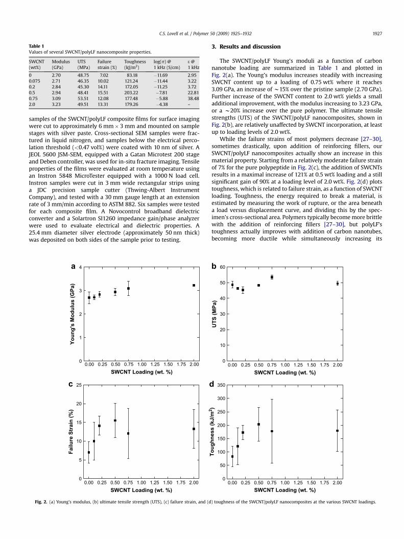
Table 1Values of several SWCNT/polyLF nanocomposite properties.
SWCNT(wt%)
Modulus(GPa)
UTS(MPa)
Failurestrain (%)
Toughness(kJ/m2)
log(s) @1 kHz (S/cm)
3 @1 kHz
0 2.70 48.75 7.02 83.18 �11.69 2.950.075 2.71 46.35 10.02 121.24 �11.44 3.220.2 2.84 45.30 14.11 172.05 �11.25 3.720.5 2.94 48.41 15.51 203.22 �7.81 22.810.75 3.09 53.51 12.08 177.48 �5.88 38.482.0 3.23 49.51 13.31 179.26 �4.38 –
C.S. Lovell et al. / Polymer 50 (2009) 1925–1932 1927
samples of the SWCNT/polyLF composite films for surface imagingwere cut to approximately 6 mm� 3 mm and mounted on samplestages with silver paste. Cross-sectional SEM samples were frac-tured in liquid nitrogen, and samples below the electrical perco-lation threshold (<0.47 vol%) were coated with 10 nm of silver. AJEOL 5600 JSM-SEM, equipped with a Gatan Microtest 200 stageand Deben controller, was used for in-situ fracture imaging. Tensileproperties of the films were evaluated at room temperature usingan Instron 5848 MicroTester equipped with a 1000 N load cell.Instron samples were cut in 3 mm wide rectangular strips usinga JDC precision sample cutter (Thwing-Albert InstrumentCompany), and tested with a 30 mm gauge length at an extensionrate of 3 mm/min according to ASTM 882. Six samples were testedfor each composite film. A Novocontrol broadband dielectricconverter and a Solartron SI1260 impedance gain/phase analyzerwere used to evaluate electrical and dielectric properties. A25.4 mm diameter silver electrode (approximately 50 nm thick)was deposited on both sides of the sample prior to testing.
0.00 0.25 0.50 0.75 1.00 1.25 1.50 1.75 2.000
5
10
15
20
25
Failu
re S
train
(%
)
SWCNT Loading (wt. %)
0.00 0.25 0.50 0.75 1.00 1.25 1.50 1.75 2.000
1
2
3
a
dc
4
Yo
un
g's
M
od
ulu
s (G
Pa)
SWCNT Loading (wt. %)
Fig. 2. (a) Young’s modulus, (b) ultimate tensile strength (UTS), (c) failure strain, and (d
3. Results and discussion
The SWCNT/polyLF Young’s moduli as a function of carbonnanotube loading are summarized in Table 1 and plotted inFig. 2(a). The Young’s modulus increases steadily with increasingSWCNT content up to a loading of 0.75 wt% where it reaches3.09 GPa, an increase of w15% over the pristine sample (2.70 GPa).Further increase of the SWCNT content to 2.0 wt% yields a smalladditional improvement, with the modulus increasing to 3.23 GPa,or a w20% increase over the pure polymer. The ultimate tensilestrengths (UTS) of the SWCNT/polyLF nanocomposites, shown inFig. 2(b), are relatively unaffected by SWCNT incorporation, at leastup to loading levels of 2.0 wt%.
While the failure strains of most polymers decrease [27–30],sometimes drastically, upon addition of reinforcing fillers, ourSWCNT/polyLF nanocomposites actually show an increase in thismaterial property. Starting from a relatively moderate failure strainof 7% for the pure polypeptide in Fig. 2(c), the addition of SWCNTsresults in a maximal increase of 121% at 0.5 wt% loading and a stillsignificant gain of 90% at a loading level of 2.0 wt%. Fig. 2(d) plotstoughness, which is related to failure strain, as a function of SWCNTloading. Toughness, the energy required to break a material, isestimated by measuring the work of rupture, or the area beneatha load versus displacement curve, and dividing this by the spec-imen’s cross-sectional area. Polymers typically become more brittlewith the addition of reinforcing fillers [27–30], but polyLF’stoughness actually improves with addition of carbon nanotubes,becoming more ductile while simultaneously increasing its
b
0.00 0.25 0.50 0.75 1.00 1.25 1.50 1.75 2.000
10
20
30
40
50
60
UT
S (M
Pa)
SWCNT Loading (wt. %)
0.00 0.25 0.50 0.75 1.00 1.25 1.50 1.75 2.000
50
100
150
200
250
300
350
To
ug
hn
ess (kJ/m
2)
SWCNT Loading (wt. %)
) toughness of the SWCNT/polyLF nanocomposites at the various SWCNT loadings.
C.S. Lovell et al. / Polymer 50 (2009) 1925–19321928
modulus and maintaining its overall strength. As shown in Fig. 2(d),the pristine sample exhibited a toughness of 83.18 kJ/m2. Thistoughness value increases by 144% for the 0.5 wt% SWCNT loading,and 116% for the 2.0 wt% sample. Note that this data was notobtained with a typical Impact Test (e.g. Charpy Test), and is merelya relative measure for comparison among the samples in this study.While the data exhibits a high standard deviation, the increase inthe composite’s toughness cannot be disregarded, particularly at0.2 and 0.5 wt%, where the toughness values are well above thepristine sample.
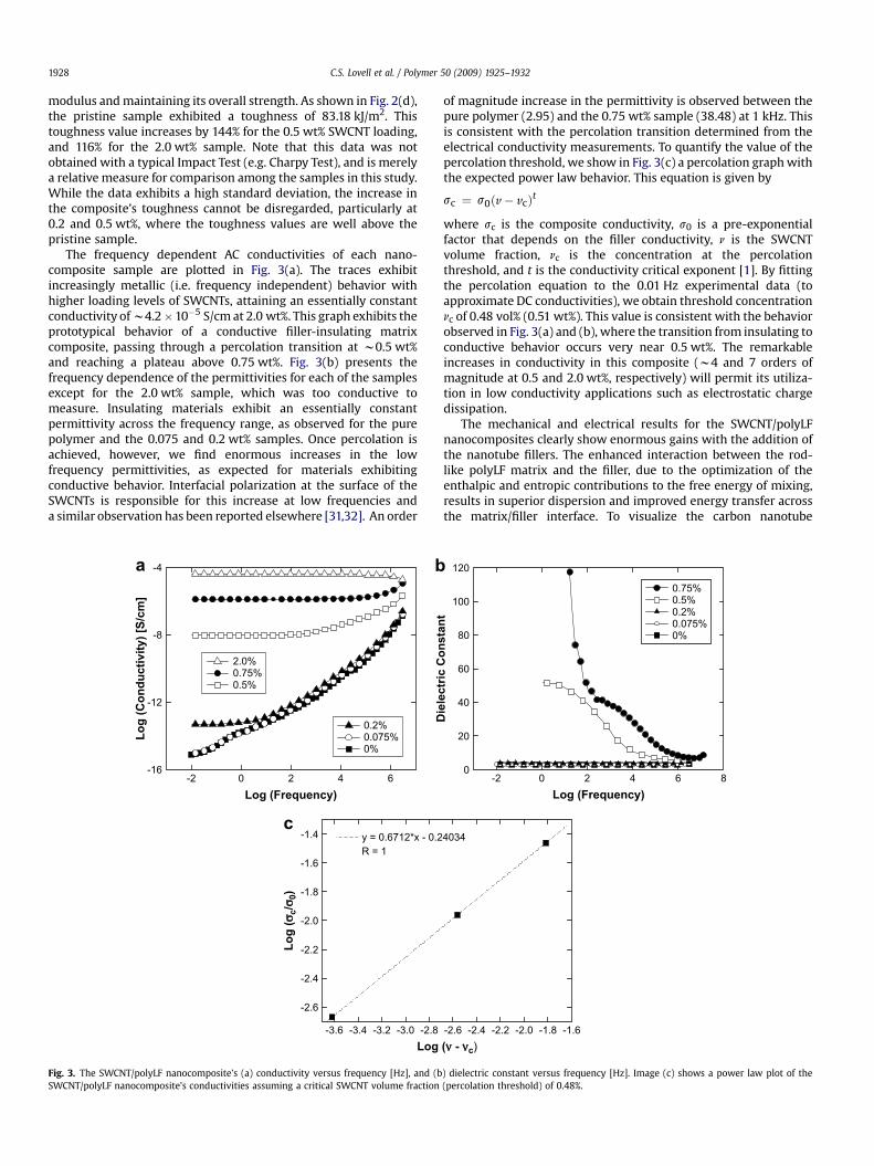
The frequency dependent AC conductivities of each nano-composite sample are plotted in Fig. 3(a). The traces exhibitincreasingly metallic (i.e. frequency independent) behavior withhigher loading levels of SWCNTs, attaining an essentially constantconductivity of w4.2�10�5 S/cm at 2.0 wt%. This graph exhibits theprototypical behavior of a conductive filler-insulating matrixcomposite, passing through a percolation transition at w0.5 wt%and reaching a plateau above 0.75 wt%. Fig. 3(b) presents thefrequency dependence of the permittivities for each of the samplesexcept for the 2.0 wt% sample, which was too conductive tomeasure. Insulating materials exhibit an essentially constantpermittivity across the frequency range, as observed for the purepolymer and the 0.075 and 0.2 wt% samples. Once percolation isachieved, however, we find enormous increases in the lowfrequency permittivities, as expected for materials exhibitingconductive behavior. Interfacial polarization at the surface of theSWCNTs is responsible for this increase at low frequencies anda similar observation has been reported elsewhere [31,32]. An order
-2 0 2 4 6-16
-12
-8
-4a b
c
0.2%0.075%0%
2.0%0.75%0.5%
Lo
g (C
on
du
ctivity) [S
/cm
]
Log (Frequency)
-3.6 -3.4 -3.2 -3.0 -2.8
-2.6
-2.4
-2.2
-2.0
-1.8
-1.6
-1.4 y = 0.6712*x - 0.2R = 1
Lo
g (
c/
0)
Log
Fig. 3. The SWCNT/polyLF nanocomposite’s (a) conductivity versus frequency [Hz], and (bSWCNT/polyLF nanocomposite’s conductivities assuming a critical SWCNT volume fraction
of magnitude increase in the permittivity is observed between thepure polymer (2.95) and the 0.75 wt% sample (38.48) at 1 kHz. Thisis consistent with the percolation transition determined from theelectrical conductivity measurements. To quantify the value of thepercolation threshold, we show in Fig. 3(c) a percolation graph withthe expected power law behavior. This equation is given by
sc ¼ s0ðv� vcÞt
where sc is the composite conductivity, s0 is a pre-exponentialfactor that depends on the filler conductivity, n is the SWCNTvolume fraction, nc is the concentration at the percolationthreshold, and t is the conductivity critical exponent [1]. By fittingthe percolation equation to the 0.01 Hz experimental data (toapproximate DC conductivities), we obtain threshold concentrationnc of 0.48 vol% (0.51 wt%). This value is consistent with the behaviorobserved in Fig. 3(a) and (b), where the transition from insulating toconductive behavior occurs very near 0.5 wt%. The remarkableincreases in conductivity in this composite (w4 and 7 orders ofmagnitude at 0.5 and 2.0 wt%, respectively) will permit its utiliza-tion in low conductivity applications such as electrostatic chargedissipation.
The mechanical and electrical results for the SWCNT/polyLFnanocomposites clearly show enormous gains with the addition ofthe nanotube fillers. The enhanced interaction between the rod-like polyLF matrix and the filler, due to the optimization of theenthalpic and entropic contributions to the free energy of mixing,results in superior dispersion and improved energy transfer acrossthe matrix/filler interface. To visualize the carbon nanotube
-2 0 2 4 6 80
20
40
60
80
100
120
Dielectric C
on
stan
t
Log (Frequency)
0.75%0.5%0.2%0.075%0%
-2.6 -2.4 -2.2 -2.0 -1.8 -1.6
4034
( - c)
) dielectric constant versus frequency [Hz]. Image (c) shows a power law plot of the(percolation threshold) of 0.48%.

0.00 0.25 0.50 0.75 1.00 1.25 1.50 1.75 2.00
1.0
1.1
1.2
1.3
1.4
1.5
Modified Cox ModelExperimental Values
No
rm
alized
Y
ou
ng
's M
od
ulu
s
SWCNT Loading (vol.%)
Fig. 5. Normalized Young’s Modulus versus SWCNT volume percent (data fitted toa modified Cox Model [34]) of the SWCNT/polyLF nanocomposite.
C.S. Lovell et al. / Polymer 50 (2009) 1925–1932 1929
dispersion, scanning electron micrographs of the SWCNT/polyLFnanocomposite film surfaces were taken, shown in Fig. 4(a) and (b).These images, representing the 0.5 and 2.0 wt% samples respec-tively, were taken at an accelerating voltage between 20 and 30 kV.The high voltages used in these micrographs create a beam thatpenetrates through the polymer matrix. These ‘‘poly-transparent’’images give better insight into the level of dispersion by revealingnanotube bundles embedded deep into the nanocomposite whichare not visible in conventional topographical images [33]. The poly-transparent images reveal flexible nanotube networks throughoutthe matrix with a few loosely entangled nanotube agglomerates.Overall, Fig. 4(a) and (b) show that reasonably uniform carbonnanotube dispersion was achieved in polyLF using only shearmixing and sonication (i.e. without resorting to surfactants orcovalent functionalization).
In Fig. 4(c)–(f), the fractured cross-sections of the 0 wt% (Fig. 4(c)and (d)) and 2.0 wt% (Fig. 4(e) and (f)) samples are shown. Carbonnanotubes can clearly be seen as thin, bright filaments in images (e)and (f), a result of the emission of secondary electrons. The 0 wt%sample images show porous fibrous morphology with thickerprotrusions and connections between polymer regions. Many ofthese connections were broken during the fracturing process, asshown in Fig. 4(d). In contrast, the 2.0 wt% sample exhibits muchfiner fibrillar structures, indicated by the thin, bright regions in the
Fig. 4. HRSEM images of the SWCNT/polyLF nanocomposite: (a) 0.5 wt% surface (b) 2.0 wt% surface, (c, d) 0% cross-section and (e, f) 2.0 wt% cross-section. The cross-sectional imagesamples were fractured in liquid nitrogen, with the 0 wt% images coated with 10 nm of silver to minimize charging.
C.S. Lovell et al. / Polymer 50 (2009) 1925–19321930
images. Also note that the SWCNTs clearly span the crevices of thenanocomposite, giving these images a threadlike, connected, andrough appearance compared to images of the pure polymer. Thisincreased roughness and persistent spanning of the crevicessuggest the mechanism for the nanocomposite’s enhancedtoughness.
To relate the filler dispersion found in the SEM images with themechanical reinforcement data, and to gain better insight on theSWCNT/polyLF Young’s modulus trend, we compare the experi-mental data to the predictions of a modified Cox Model [34]. Thismodel builds upon the original Cox model, which is a variation onthe rule of mixtures. The composite modulus is expressed as anadditive combination of the SWCNT and matrix contributions:
EC ¼ EFVFf ðlFÞC0 þ EMð1� VFÞ
where EC, EF, EM are the Young’s Moduli of the composite, SWCNTand matrix, respectively, and VF is the volume fraction of the carbonnanotubes. The C0 term is added to allow for SWCNT alignmentsother than uniaxial, which is the only arrangement considered inthe simple rule of mixtures. In the limit of f(lF) and C0 equal to unity,
b
0.0 0.2 0.4 0.60.0
0.2
0.4
0.6
0.8
1.0
1.2
1.4
Fo
rce (N
)
Displacem
a
b
d
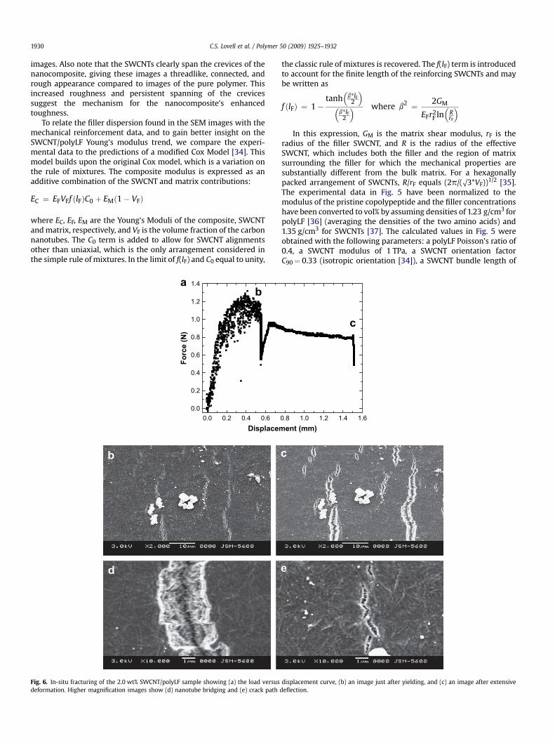
Fig. 6. In-situ fracturing of the 2.0 wt% SWCNT/polyLF sample showing (a) the load versusdeformation. Higher magnification images show (d) nanotube bridging and (e) crack path
the classic rule of mixtures is recovered. The f(lF) term is introducedto account for the finite length of the reinforcing SWCNTs and maybe written as
f ðlFÞ ¼ 1�tanh
�b*lF
2
��
b*lF2
� where b2 ¼ 2GM
EFr2F ln�
RrF
�
In this expression, GM is the matrix shear modulus, rF is theradius of the filler SWCNT, and R is the radius of the effectiveSWCNT, which includes both the filler and the region of matrixsurrounding the filler for which the mechanical properties aresubstantially different from the bulk matrix. For a hexagonallypacked arrangement of SWCNTs, R/rF equals (2p/(O3*VF))1/2 [35].The experimental data in Fig. 5 have been normalized to themodulus of the pristine copolypeptide and the filler concentrationshave been converted to vol% by assuming densities of 1.23 g/cm3 forpolyLF [36] (averaging the densities of the two amino acids) and1.35 g/cm3 for SWCNTs [37]. The calculated values in Fig. 5 wereobtained with the following parameters: a polyLF Poisson’s ratio of0.4, a SWCNT modulus of 1 TPa, a SWCNT orientation factorC90¼ 0.33 (isotropic orientation [34]), a SWCNT bundle length of
c
0.8 1.0 1.2 1.4 1.6ent (mm)
c
e
displacement curve, (b) an image just after yielding, and (c) an image after extensivedeflection.
C.S. Lovell et al. / Polymer 50 (2009) 1925–1932 1931
1 mm, and a SWCNT bundle diameter of 32 nm. These are all typicalvalues for polymers and carbon nanotubes, and the bundledimensions were estimated from HRSEM images of pure SWCNTsand nanocomposite cross-sectional images. Fig. 5 shows that themodel predictions are in good agreement with the experimentaldata up to the 0.75 wt% (0.69 vol%) sample. At 2.0 wt% (1.83 vol%),however, the experimental Young’s modulus does not exhibit thecontinued increase in modulus predicted by the current model. Thefailure of the model to predict the modulus at higher loadings couldbe due to its assumption that the level of dispersion is preserved athigher loadings. The presence of small bundles of overlappingcarbon nanotubes at higher volume fractions would result ina sublinear increase of surface area with respect to volume fraction.As the interfacial interaction of the SWCNTs with the matrixdepends directly on the exposed surface area, the model wouldtend to over-predict the modulus as bundling increases.
In order to investigate the origin of the increased SWCNT/polyLFtoughness, we performed in-situ tensile tests in a JEOL 5600 JSM-SEM fitted with a Gatan Microtest 200 stage and Deben controller.An in-situ load–displacement curve for a 2.0 wt% SWCNT/polyLFsample performed inside of the SEM chamber is shown in Fig. 6(a).Fig. 6(b) and (c) show consecutive SEM images of one locationobtained just after yielding, and after extensive deformation,respectively, which correspond to the (b) and (c) markers on theload–displacement curve in Fig. 6(a). The load drops at (b) and (c) inthis figure indicate a stress relaxation which occurred whileholding the strain constant during imaging. The progressive initi-ation and slow propagation of many small cracks shown in Fig. 6(b)and (c), as opposed to one catastrophic crack in brittle failure, atleast partially accounts for the high energy absorption and tough-ness that this material exhibits. In general, crack fronts can changein length as they interact with inhomogeneous inclusions. Manynanotubes in the percolated network throughout the matrix caninteract with the crack fronts, absorbing large amounts of energyand toughening the composite. In the close-up image shown inFig. 6(d), it is apparent that small cracks are held together by theSWCNTs and this bridging is likely to be one of the major tough-ness-improving mechanisms. This spanning by carbon nanotubescan also be seen clearly in the cross-sectional images of Fig. 4(e) and(f) discussed earlier. The strong, flexible, and ductile SWCNTs actlike a thermoplastic toughener by bridging cracks and exertingcompressive traction in the crack wake [38]. The SWCNTs are pulledout during the crack opening process, absorbing significantamounts of energy due to the large interfacial area between theSWCNTs and the matrix. Carbon nanotubes, which have extremelylarge aspect ratios, are particularly effective for crack bridging, asthis mechanism tends to favor larger fillers [39]. Better dispersionand more interfacial bonding, which occur between our specificallydesigned copolypeptide and SWCNTs, can provide higher energyabsorption resulting in enhanced toughness. Another mechanismfor increasing the work of rupture is effective crack path deflectionby the uniformly dispersed nanotubes, as in Fig. 6(e). This deflec-tion changes the crack propagation from a mode-I (tensile) tomode-II (shear) failure character, which enhances energy absorp-tion as most materials are more resistant to this latter type of crackopening. Other obvious contributors to the improved toughness arephysical entanglements of nanotubes and nanotube bundle bifur-cation/splitting as shown in Fig. 4(f). Ubiquitous physical entan-glements and bifurcated/split nanotubes have been reported before[40]. This characteristic enables good energy absorption as a resultof the excellent binding forces between the nanotubes in thebundles during fracture. In-situ SEM images of the fracturednanocomposite shown in Fig. 6 substantiate the toughness resultsdiscussed above, and illustrate how excellent dispersion andenhanced compatibility between the polyLF and the SWCNTs
provide a more mechanically robust composite for various sensingand actuation applications.
4. Conclusions
Nanocomposites consisting of a Leucine–Phenylalanine copoly-peptide and single wall carbon nanotubes were developed bya simple mixing and sonicating technique. This particular copoly-peptide was designed to provide both a favorable enthalpic stabi-lization from the presence of aromatic sidechains, and to minimizethe unfavorable entropic contributions due to its helical secondarystructure. The improved compatibility achieved in this systemresults in excellent filler dispersion in the matrix, as demonstratedin the scanning electron micrographs. Furthermore, it leads toa remarkable increase in many of the copolypeptide’s physicalproperties, including elastic modulus, failure strain, toughness,conductivity, and dielectric constant. The increases in failure strainand toughness are perhaps the most intriguing, considering thatpolymers with reinforcing fillers typically show reductions in bothproperties. These results show that carbon nanotubes can provideenhanced durability and conductivity to many of the otherwisefragile copolypeptides which may be needed for harsh sensing oractuation applications.
Acknowledgements
The authors thank Nancy M. Holloway for electroding thesamples. They also acknowledge Timothy Deming, Galen Stuckyand Edward Worthington for supplying the LF copolypeptide. Lovellappreciates the guidance and discussion of Dr. James M. Fitz-Geraldat the University of Virginia. Park and Wise appreciate NASAUniversity Research, Engineering and Technology Institute on BioInspired Materials (BIMat) under Award No. NCC-1-02037 forsupport in part.
References
[1] Park C, Ounaies Z, Watson KA, Crooks RE, Smith J, Lowther SE, et al. ChemicalPhysics Letters 2002;364(3–4):303–8.
[2] Breuer O, Sundararaj U. Polymer Composites 2004;25(6):630–45.[3] Haggenmueller R, Gommans HH, Rinzler JE, Fischer JE, Winey KI. Chemical
Physics Letters 2000;330(3–4):219–25.[4] Potschke P, Abdel-Goad M, Alig I, Dudkin S, Lellinger D. Polymer 2004;
45(26):8863–70.[5] Moniruzzaman M, Winey KI. Macromolecules 2006;39(16):5194–205.[6] Asakura S, Oosawa F. Journal of Chemical Physics 1954;22:1255–6.[7] Asakura S, Oosawa F. Journal of Polymer Science 1958;33:183–91.[8] Vrij A. Pure Applied Chemistry 1976;48:471.[9] More extensive discussions of the difficulties of preparing stable nano-
composites filled with carbon nanotubes [41–44] and other rod-like polymers[45–52] are available in the literature.
[10] Petit P, Derre A, Anglaret E, Poulin P, Penicaud A. Journal of the AmericanChemical Society 2005;127(1):8–9.
[11] Wise KE, Park C, Siochi EJ, Harrison JS. Chemical Physics Letters 2004;391(4–6):207–11.
[12] Poenitzsch VZ, Winters DC, Xie H, Dieckmann GR, Dalton AB, Musselman IH.Journal of the American Chemical Society 2007;129(47):14724–32.
[13] Wise KE, Park C, Kang JK, Siochi EJ, Harrison JS. Nanocomposites from stabledispersions of carbon nanotubes in polymeric matrices using dispersioninteractions. International Publication No: WO/2008/073153, PCT/US2007/016723.
[14] Chen RJ, Zhang Y, Wang D, Dai H. Journal of the American Chemical Society2001;123(16):3838–9.
[15] Grimme S. Angewandte Chemie (International Ed.) 2008;47(18):3430–4. Inaccordance with the conclusions reached by Grimme, we avoid using theambiguous term ‘‘pi–pi interaction’’ to describe the interaction between thephenyl ring of phenylalanine and the SWCNT. We also note that we do notcurrently have any experimental evidence proving that the phenyl ring lies ina stacked geometrical configuration with respect to the nanotube, althoughpreliminary modeling results do suggest that this is the case.
[16] Polypeptides can be tailored to optimize their interactions with carbonnanotubes by judiciously choosing the appropriate amino acid sequence. Seefor example refs [12,53–58].

C.S. Lovell et al. / Polymer 50 (2009) 1925–19321932
[17] Nygren P, Lundqvist M, Broo K, Jonsson BH. Nano Letters 2008;8(7):1844–52.[18] The polyLF was provided by the Deming Group, formerly at the University of
California, Santa Barbara, and currently at the University of California, LosAngeles.
[19] Miyazawa T, Blout ER. Journal of the American Chemical Society 1961;83:712–9.[20] Linder R, Nispel M, Haber T, Kleinermanns K. Chemical Physics Letters
2005;409(4–6):260–4.[21] Oren Z, Ramesh J, Avrahamil D, Suryaprakash N, Shai Y, Jelinek R. European
Journal of Biochemistry 2002;269(16):1–12.[22] Le Coutre J, Kaback HR, Patel CKN, Heginbotham L, Miller C. Proceedings of the
National Academy of Sciences of the United States of America1998;95(11):6114–7.
[23] Papadopoulus P, Floudas G, Klok HA, Schnell I, Pakula T. Biomacromolecules2004;5(1):81–91.
[24] Liu Y, Cho R-K, Sakurai K, Miura T, Ozaki Y. Applied Spectroscopy1994;48(10):1249–54.
[25] Higashi N, Kawahara J, Niwa M. Journal of Colloid and Interface Science2005;288(1):83–7.
[26] Garg A, Sinnott SB. Chemical Physics Letters 1998;295(4):273–8.[27] Wang SF, Shen L, Zhang WD, Tong YJ. Biomacromolecules 2005;6(6):3067.[28] Xu C, Jia Z, Wu D, Han Q, Meek T. Journal of Electronic Materials
2006;35(5):954–7.[29] Xu M, Zhang T, Gu B, Wu J, Chen Q. Macromolecules 2006;39(10):3540–5.[30] Meincke O, Kaempfer D, Weickmann H, Friedrich C, Vathauer M, Warth H.
Polymer 2004;45(3):739–48.[31] Kim B, Lee J, Yu I. Journal of Applied Physics 2003;94(10):6724–8.[32] Park C, Kang JH, Harrison JS, Costen RC, Lowther SE. Advanced Materials
2008;20(11):2074–9.[33] Kovacs JZ, Andresen K, Pauls JR, Garcia CP, Schossig M, Schulte K, et al. Carbon
2007;45(6):1279–88.[34] Kelly A, Zweben CH, editors. Comprehensive Composite Materials. Amster-
dam: Elsevier Science; 2000.[35] Fu SY, Lauke B. Composites Science and Technology 1998;58(3–4):389–400.[36] Weast RC, editor. CRC handbook of chemistry and physics. Cleveland: CRC
Press; 1977.[37] Gao G, Cagin T, Goddard WA. Nanotechnology 1998;9(3):184–91.
[38] Riew CK, Kinloch AJ. Advances in chemistry series no 233. Washington:American Chemical Society; 1993.
[39] Sigl LS, Mataga PA, Dalgleish BJ, McMeeking RM, Evans AG. Acta Metallurgica1988;36(4):945–53.
[40] McLachlan DS, Chiteme C, Park C, Wise KE, Lowther SE, Lillehei PT, et al.Journal of Polymer Science Part B: Polymer Physics 2005;43(22):3273–87.
[41] Szleifer I, Yerushalmi-Rozen R. Polymer 2005;46(19):7803–18.[42] Shvartzman-Cohen R, Nativ-Roth E, Baskaran E, Levi-Kalisman Y, Szleifer I,
Yerushalmi-Rozen R. Journal of the American Chemical Society 2004;126(45):14850–7.
[43] Shvartzman-Cohen R, Levi-Kalisman Y, Nativ-Roth E, Yerushalmi-Rozen R.Langmuir 2004;20(15):6085–8.
[44] Grossiord N, Loos J, Regev O, Koning CE. Chemistry of Materials 2006;18(5):1089–99.
[45] Ballauff M. Polymers for Advanced Technologies 1990;1:109–16.[46] Schartel B, Wendorff JH. Polymer Engineering and Science 1999;39:128–51.[47] Dudowicz J, Freed KF, Douglas JF. Journal of Chemical Physics 2002;
116(22):9983–96.[48] Surve M, Pryamitsyn V, Ganesan V. Macromolecules 2007;40(2):344–54.[49] Liu AJ, Fredrickson GH. Macromolecules 1993;26(11):2817–24.[50] Liu AJ, Fredrickson GH. Macromolecules 1996;29(24):8000–9.[51] Weinhold JD, Kumar SK, Singh C, Schweizer KS. Journal of Chemical Physics
1995;103(21):9460–74.[52] Foreman KW, Freed KF. Macromolecules 1997;30(23):7279–95.[53] Dieckmann GR, Dalton AB, Johnson PA, Razal J, Chen J, Giordano GM, et al.
Journal of the American Chemical Society 2003;125(7):1770–7.[54] Zorbas V, Ortiz-Acevedo A, Dalton AB, Yoshida MM, Dieckmann GR, Draper RK,
et al. Journal of the American Chemical Society 2004;126(23):7222–7.[55] Nicolosi V, Cathcart H, Dalton AR, Aherne D, Dieckmann GR, Coleman JN.
Biomacromolecules 2008;9(2):598–602.[56] Wang S, Humphreys ES, Chung SY, Delduco DF, Lustig SR, Wang H, et al. Nature
Materials 2003;2:196–200.[57] Pender MJ, Sowards LA, Hartgerink JD, Stone MO, Naik RR. Nano Letters
2006;6(1):40–4.[58] Su Z, Leung T, Honek JF. Journal of Physical Chemistry B 2006;110(47):
23623–7.