A usage-based analysis of alternating syntactic constructions
JoMA (2014) 11-26 © STM Journals 2014. All Rights Reserved Page 11
Journal of Mechatronics and Automation
Volume 1, Issue 1
www.stmjournals.com
Theoretical and Experimental Investigation of Non-linear
Vibration Response of an IPMC Actuator Subjected to
Alternating Electric Potential
Dillip Kumar Biswal, Dibakar Bandopadhya*, Santosha Kumar Dwivedy Department of Mechanical Engineering, Indian Institute of Technology Guwahati,
Guwahati, Assam, India
Abstract The precise predication of stable and unstable zone for an applied excitation voltage and
frequency is of importance in many micromechanical systems utilizing ionic polymer
metal composite (IPMC) as the actuator. A linear dynamic model thus will no longer be valid for IPMC actuator having low thickness and thus more flexible. In this article, non-
linear vibration characteristics of a silver (Ag) based IPMC actuator is studied under alternating electric potential in inextensible condition. The IPMC actuator of silver
electrode is fabricated first using Nafion as the base polymer following the chemical
decomposition method. A theoretical model of motion has been derived using experimental bending data and following the D’Alembert’s principle that describes the
nonlinear vibration characteristics of the actuator. Generalized Galerkin’s method is
then utilized to discretize the equation of motion. Method of Multiple Scales has been used to solve the non-linear equation of motion. Simulations have been performed taking
into account the experimental data and by solving the temporal equation of motion of the system. Several experiments are conducted with an IMPC actuator in fixed-free
configuration and vibration response is studied applying the alternating electric
potential. Both transient and steady-state response of the system is studied and the theoretical results are validated and correlated with the experimental results.
Keywords: Ionic polymer-metal composites, non-linear vibration, D’Alembert’s
principle, Galerkin’s method, method of multiple scales
*Author for Correspondence E-mail: [email protected], [email protected]
INTRODUCTION Polymeric active material technologies are
being developed; that closely matches with the
properties of natural muscle systems; such as
produce similar strains and higher stresses,
shrinks and swells using electrostatic forces,
electrostriction, ion insertion, and sometimes
molecular conformational changes.
Particularly, ionic polymer metal composite
(IPMC) a class of electro-active polymers
(EAPs) have received much attention
nowadays both for sensing and actuation
related application. When an external electric
potential of magnitude 1–3V is applied, IPMC
shows considerable bending deformation;
conversely a measurable output voltage is
obtained across its surface when it is deformed
mechanically. These unique properties make
them suitable for being used both as actuator
and sensor [1,2]. In addition, attractive
features such as large bending deformation
with low driving voltage, light weight,
actuation capability in water as well as in air,
make IPMC suitable for application such as in
the field of micro-robotics, biomedical,
marine, artificial muscles, aerospace etc.
[3–6]. It is well accepted that the mobility of
ion-water cluster causes swelling near the
cathode electrode and equivalent contraction
on the other side results bending of IPMC
actuator. Further, it has been shown that, the
bending deformation depends on various
factors such as magnitude and direction of
applied electric potential, moisture content in
the base polymer etc. [7]. IPMC usually
consists of an ion-exchange polymer (IEP)
membrane (Nafion/Flemion), coated with
electrodes made up of high conducting pure
Non-linear Vibration Response of an IPMC Actuator Biswal et al.
JoMA (2014) 11-26 © STM Journals 2014. All Rights Reserved Page 12
metals like platinum (Pt) or gold (Au) [2, 8,9];
however, it incurs high manufacturing cost. To
reduce production cost, non-precious metals
such as silver (Ag) as electrode material was
proposed for fabrication of IPMC material
[10–12].
When a low magnitude alternative electric
potential (1-2V) is applied to a fully hydrated
IPMC actuator, it shows a considerable
bending vibration at that applied frequency.
An analytical model has been developed for an
IPMC actuator using Euler-Bernoulli’s beam
theory and the vibration response was studied
[13]. Euler-Bernoulli beam theory and the
concept of hydrodynamic functions were used
to develop a theoretical model [14] to find out
the vibration response of an IPMC actuator in
a fluid medium and the results were validated
experimentally. Nonlinear response of IPMC
actuator has been observed under step input
due to various factors such as permanent
strain, [15] or remnant deformation [16] or due
to moisture loss in open environment during
working condition, [17]. Further, an
experimental investigation was carried out of
IPMCs in different solvents forms in
cantilever link configuration to characterize
the nonlinearities in actuation response using
the Volterra series [18]. In application to
walking robots, [19] a model has been
developed applying Hammerstein technique to
identify nonlinearity in IPMC materials. A
two-stage nonlinear electromechanical model
was developed to characterize the actuation
behavior of the IPMC [20]. A nonlinear black-
box model, based on the recurrent multi-layer
perceptron neural network and self-adjustable
learning mechanism was developed [21] to
measure the tip displacement. A simulink
model was developed for an elastic cantilever
beam using nonlinear equation assuming large
angle deflection that demonstrates the static
and dynamic deflection [22,23].
It is experimentally observed that an IPMC
actuator displays considerable mechanical
vibration during actuation. Where, with small
scale displacement and motion, effect of
dehydration and non-linearity of the system in
response become significant aspect when
accurate measurement is required. In micro-
scale applications, small change in amplitude
of vibration or excitation input may bring the
system into non-linear regime, and this
motivates to utilize the non-linear analysis to
predict the behavior of the system more
accurately. However, till date very limited
research has been carried out on non-linear
response and to develop a suitable model that
addresses the nonlinear vibration
characteristics of IPMC actuator, excited
under a low magnitude alternating electric
potential. Though development of a
comprehensive model is still going on, factors
such as dynamic response and nonlinearities of
IPMC have received low attention in the
previous work. Thus, it is relevant to address
and investigate the nonlinear response of
IPMC actuator. In this work, an IPMC actuator
is analyzed in cantilever mode configuration
under alternating electric potential to study the
nonlinear-vibration characteristics. Initially,
IPMCs are fabricated using Nafion as the base
polymer while non-precious metal silver as the
surface electrode following the chemical
decomposition method. The actuator is
modeled following the Euler-Bernoulli
approach treating it as flexible distributed
parameter system. The governing equation of
motion has been developed using
D’Alembert’s principle and the generalized
Galerkin’s method has been used to derive the
temporal equation of motion. A closed form
expression for the response amplitude and the
detuning parameter has been developed and is
used to obtain the nonlinear frequency
response curve for the IPMC actuator. This
simplified expression can be used for finding
the response of the system instead of solving
the temporal equation of motion of the system
which is time consuming and requires more
memory space. Method of multiple-scales has
been applied to solve the temporal equation of
motion and subsequently obtain the steady-
state response and stability of the system. The
influence of various system parameters such as
amplitude, and frequency of the applied
electric potential on the frequency response
curves have also been investigated for simple
resonance condition. Time and frequency
response along with phase portrait have been
plotted to study the system response. The
result obtained from perturbation analysis has
been compared with those obtained by solving
the temporal equation of motion and are found
to be in good agreement. Further, the
numerical results are compared and verified by
Journal of Mechatronics and Automation
Volume 1, Issue 1
JoMA (2014) 11-26 © STM Journals 2014. All Rights Reserved Page 13
performing experiment. The theoretical results
clearly predict the stable and unstable zone
and the range of the frequencies of the regime.
The results are validated experimentally for a
number of frequencies both in stable, unstable
and steady-state and transient response regime.
BENDING CHARACTERISTICS The current state-of-the-art procedure to
fabricate this smart material of superior
performance is expensive as the surface
electrode material used mostly is Platinum or
Gold. It is anticipated that by optimizing
process and operating parameters and using
non-precious metal as the surface electrode
may reduce the needs of costly precious
material. In the present study, non-precious
metal silver (Ag) is used for electrode material
that reduces the cost of fabrication and at the
same time is shown to be improving the
performance of IPMC.
IPMCs are first fabricated following the
chemical decomposition method. A Nafion
membrane with an equivalent weight (EW) of
1100 g/mol and 0.183 mm thick, (purchased
from Ion Power, Inc, New Castle, DE 19720
USA) is used as the base polymer. The
fabrication process comprises multi-steps
including pretreatment, adsorption, reduction
and developing. Silver nitrates GR (AgNO3),
Ammonia solution (NH3), Sodium hydroxide
(NaOH), Dextrose anhydrous GR (C6H12O6),
(purchased from Merck Specialities Private
Limited, India) are used for fabrication. The
pre-treated Nafion membrane is immersed in
NaOH, 0.5 mol/L solution followed by
Diamminesilver (I) hydroxide [Ag (NH3)2OH],
0.15 mol/L solution to allow Na+ and Ag
(NH3)2+ diffuse into the membrane via ion-
exchange process. C6H12O6, 0.088mol/L is
used as the reducing agent for depositing silver
particles over the Nafion membrane surface.
Finally, the silver coated membrane is
trimmed from all sides to avoid any shorting
between two surfaces. Figure 1 shows the
photograph of a fabricated Ag-IPMC sample.
In the current method of fabrication of silver
electrode IPMCs, several steps of trial-and-
error method were carried out for optimizing
the process parameters as detailed procedure
was not outlined in the previously published
work [10]. Further, the composition of
chemicals used in the current method is
different from those used in the previous work
[10]. Also, the developed IPMC exhibits
superior performance in terms of bending
actuation, tip force including low power
consumption. Further, morphological studies
of the fabricated IPMC show no crack
formation in the micro-structure (with 1.17kX
magnification). It is observed that the average
operating life of the IPMC is around 90–100s.
The membrane can work again upon full
hydration by putting it into deionized/distilled
water. The fabricated IPMC exhibits superior
performance also shows no oxidation problem.
Before starting the experiment, IPMC is
immersed into ammonium hydroxide solution
for considerable time to prevent oxidation
problem, if any, as the ammonium hydroxide
dissolves silver oxide.
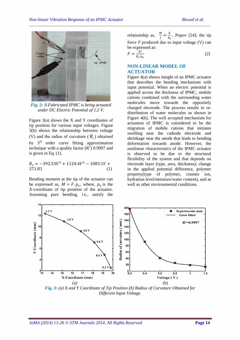
Experiment is conducted with an IPMC
actuator of size 20 x 5 x 0.2 (mm3)
in fixed-free configuration under varying input
voltage. Water is used as polar solvent. Copper
strips are used across the fixed end and voltage
is applied from a DC power supply (0–32 V,
0–2 A) and subsequently bending of IPMC is
measured. The IPMC has been subjected to
input voltage from 0.2 to 1.2 V with an
increment of 0.2 V each step. For each input
voltage after 30s, tip deflection of the IPMC is
measured to avoid any back relaxation. Figure
2 shows the bending configuration of the
IPMC actuator subjected to input of 1.2 V.
Fig. 1: Photograph of the Fabricated IPMC.
Non-linear Vibration Response of an IPMC Actuator Biswal et al. __________________________________________________________________________________________
JoMA (2014) 11-26 © STM Journals 2014. All Rights Reserved Page 14
Fig. 2: A Fabricated IPMC is being actuated
under DC Electric Potential of 1.2 V.
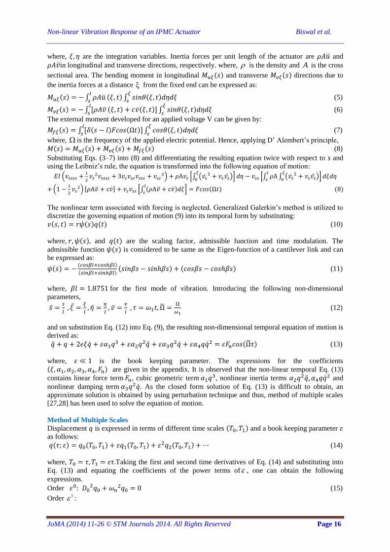
Figure 3(a) shows the X and Y coordinates of
tip position for various input voltages. Figure
3(b) shows the relationship between voltage
(V) and the radius of curvature ( cR ) obtained
by 3rd
order curve fitting approximation
technique with a quality factor (R2) 0.9997 and
is given in Eq. (1).
(1)
Bending moment at the tip of the actuator can
be expressed as, , where, is the
X-coordinate of tip position of the actuator.
Assuming pure bending, i.e., satisfy the
relationship as,
Popov [24]; the tip
force produced due to input voltage (V) can
be expressed as:
(2)
NON-LINEAR MODEL OF
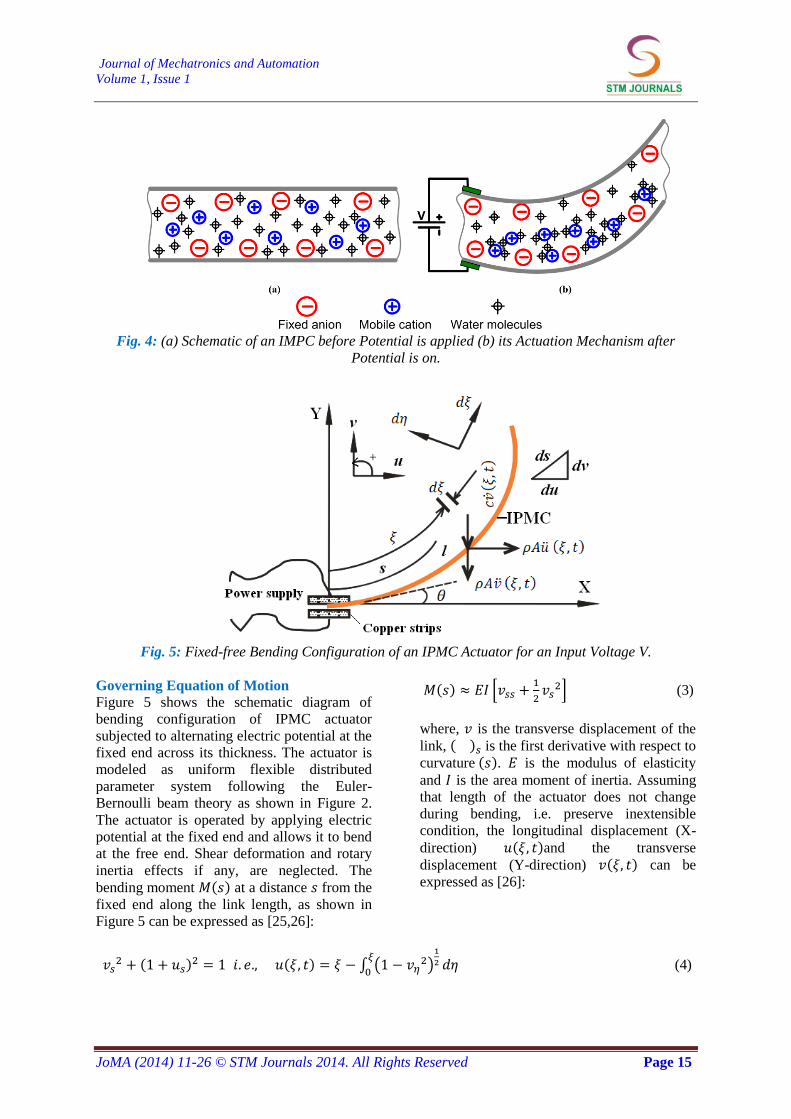
ACTUATOR Figure 4(a) shows insight of an IPMC actuator
that describes the bending mechanism with
input potential. When an electric potential is
applied across the thickness of IPMC, mobile
cations combined with the surrounding water
molecules move towards the oppositely
charged electrode. The process results in re-
distribution of water molecules as shown in
Figure 4(b). The well accepted mechanism for
actuation of IPMC is considered to be the
migration of mobile cations that initiates
swelling near the cathode electrode and
shrinkage near the anode that leads to bending
deformation towards anode. However, the
nonlinear characteristics of the IPMC actuator
is observed to be due to the structural
flexibility of the system and that depends on
electrode layer (type, area, thickness); change
in the applied potential difference, polymer
property(type of polymer, counter ion,
hydration level/moisture/water content), and as
well as other environmental conditions.
(a) (b)
Fig. 3: (a) X and Y Coordinate of Tip Position (b) Radius of Curvature Obtained for
Different Input Voltage.
Journal of Mechatronics and Automation
Volume 1, Issue 1
JoMA (2014) 11-26 © STM Journals 2014. All Rights Reserved Page 15
Fig. 4: (a) Schematic of an IMPC before Potential is applied (b) its Actuation Mechanism after
Potential is on.
Fig. 5: Fixed-free Bending Configuration of an IPMC Actuator for an Input Voltage V.
Governing Equation of Motion
Figure 5 shows the schematic diagram of
bending configuration of IPMC actuator
subjected to alternating electric potential at the
fixed end across its thickness. The actuator is
modeled as uniform flexible distributed
parameter system following the Euler-
Bernoulli beam theory as shown in Figure 2.
The actuator is operated by applying electric
potential at the fixed end and allows it to bend
at the free end. Shear deformation and rotary
inertia effects if any, are neglected. The
bending moment ( ) at a distance from the
fixed end along the link length, as shown in
Figure 5 can be expressed as [25,26]:
( ) [
] (3)
where, is the transverse displacement of the
link, ( ) is the first derivative with respect to
curvature ( ). is the modulus of elasticity
and is the area moment of inertia. Assuming
that length of the actuator does not change
during bending, i.e. preserve inextensible
condition, the longitudinal displacement (X-
direction) ( )and the transverse
displacement (Y-direction) ( ) can be
expressed as [26]:
( )
( ) ∫ ( )
(4)
Non-linear Vibration Response of an IPMC Actuator Biswal et al.
JoMA (2014) 11-26 © STM Journals 2014. All Rights Reserved Page 16
where, are the integration variables. Inertia forces per unit length of the actuator are and
in longitudinal and transverse directions, respectively. where, is the density and A is the cross
sectional area. The bending moment in longitudinal ( ) and transverse ( ) directions due to
the inertia forces at a distance from the fixed end can be expressed as:
( ) ∫
( ) ∫ ( )
(5)
( ) ∫
( ) ( ) ∫ ( )
(6)
The external moment developed for an applied voltage V can be given by:
( ) ∫ ( ) ( )
∫ ( )
(7)
where, is the frequency of the applied electric potential. Hence, applying D’ Alembert’s principle,
( ) ( ) ( ) ( ) (8)
Substituting Eqs. (3–7) into (8) and differentiating the resulting equation twice with respect to s and
using the Leibniz’s rule, the equation is transformed into the following equation of motion:
(
) [∫ (
)
] [∫ ∫ (
)
]
(
) [∫ ( )
] ( ) ( )
The nonlinear term associated with forcing is neglected. Generalized Galerkin’s method is utilized to
discretize the governing equation of motion (9) into its temporal form by substituting:
( ) ( ) ( ) (10)
where, ( ) and ( ) are the scaling factor, admissible function and time modulation. The
admissible function ( ) is considered to be same as the Eigen-function of a cantilever link and can
be expressed as:
( ) ( )
( )( ) ( ) (11)
where, for the first mode of vibration. Introducing the following non-dimensional
parameters,
(12)
and on substitution Eq. (12) into Eq. (9), the resulting non-dimensional temporal equation of motion is
derived as:
( ) (13)
where, is the book keeping parameter. The expressions for the coefficients
( ) are given in the appendix. It is observed that the non-linear temporal Eq. (13)
contains linear force term , cubic geometric term , nonlinear inertia terms
and
nonlinear damping term . As the closed form solution of Eq. (13) is difficult to obtain, an
approximate solution is obtained by using perturbation technique and thus, method of multiple scales
[27,28] has been used to solve the equation of motion.
Method of Multiple Scales
Displacement is expressed in terms of different time scales ( ) and a book keeping parameter
as follows:
( ) ( ) ( ) ( ) (14)
where, Taking the first and second time derivatives of Eq. (14) and substituting into
Eq. (13) and equating the coefficients of the power terms of , one can obtain the following
expressions.
Order
(15)
Order 1 :
Journal of Mechatronics and Automation
Volume 1, Issue 1
JoMA (2014) 11-26 © STM Journals 2014. All Rights Reserved Page 17
( )
(
) (
)
( ) (16)
The general solution of the Eq. (15) is of the form:
( ) ( )
(17)
Substituting the value of 0q into Eq. (16), and expressing ( ) in exponential form:
(
) (
)
(18)
where, stands for the complex conjugate of preceding terms. It is observed that any solution of Eq.
(18) contains both secular and mixed-secular terms when frequency of the electric potential is
nearly equal to 1. This gives rise to simple resonance case and is discussed in the following section.
For the simple resonance case, a detuning parameter is used to express the near-ness of to 1
as: ( ), and ( ). Eliminating the secular or small divisor terms of Eq. (18), yields,
(19)
Substituting,
, and
and separating the real and imaginary parts of the resulting
equation and introducing into the Eq. (19), the modulation frequency and amplitude are
obtained as:
( ) (20)
( ) (21)
For steady-state motions, . Thus, the steady-state frequency response of the system can be
obtained by solving Eqs. (20, 21) simultaneously. Eliminating from Eqs. (20, 21), one may find the
relation between and a as:
√(
) (
)
(22)
where, {
} Eq. (22) is an implicit form for amplitude of the response as a function
of excitation frequency, damping ratio and other system parameters. It is observed that, Eq. (22)
does not possess any trivial solution. The stability of the steady-state frequency response can be
determined, by perturbing the Eqs. (20) and (21), and substituting and .
where, ( ) are the singular points, and further investigating the Eigen-values of the Jacobian
matrix (J) which is obtained as:
[
{
}
] (23)
For simple resonance condition, the system with steady-state motion will be stable, if and only if all
the real parts of the Eigen-values are negative. As on Eq. (17), the first-order non-trivial approximate
steady-state solution is given as:
( ) (24)
Non-linear Vibration Response of an IPMC Actuator Biswal et al.
JoMA (2014) 11-26 © STM Journals 2014. All Rights Reserved Page 18
RESULTS AND DISCUSSIONS Numerical Results
An IPMC actuator is numerically studied and
non-linear response is investigated. The
various parameters and physical properties are
shown in Table 1. Modulus of elasticity of the
actuator in hydrated state is obtained by
conducting micro-tensile test (maker: Deben
UK Ltd., model: Microtest 5 kN). Anticipating
low amplitude vibration, book-keeping
parameter is taken 0.1 and scaling factor
r is selected as 0.1 for simulation. The
scaling factor ‘r’ is the dimensional parameter
of length that depends on thickness, width, and
the length of the ‘centre of mass’ of the IPMC
from the base. Eq. (22) is solved and the
results are verified with the results obtained by
solving the temporal equation of motion (13).
The multiple equilibrium points obtained in
the frequency response curve is validated by
plotting the basin of attraction.
As evident, due to the presence of various non-
linear terms in the temporal Eq. (13), the
system yields a typical non-linear behavior.
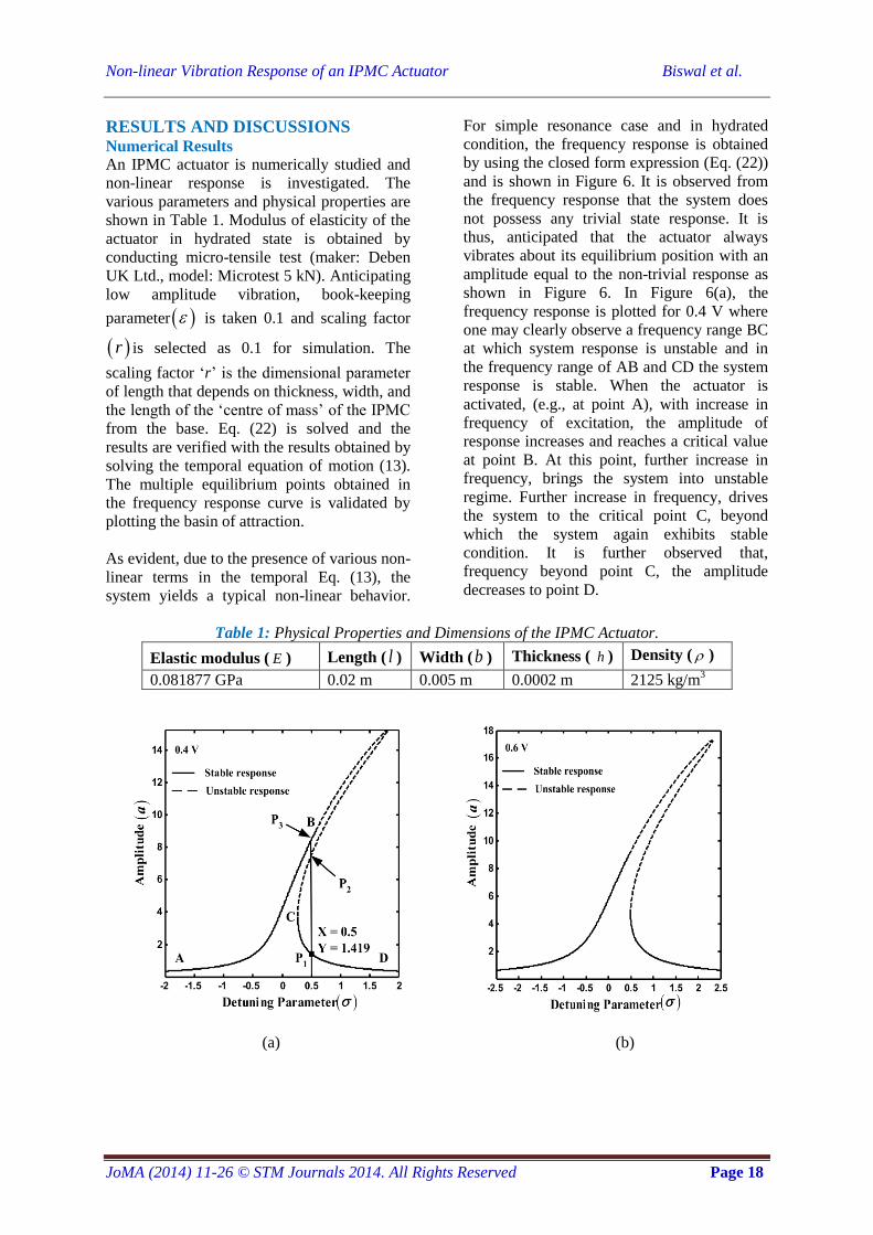
For simple resonance case and in hydrated
condition, the frequency response is obtained
by using the closed form expression (Eq. (22))
and is shown in Figure 6. It is observed from
the frequency response that the system does
not possess any trivial state response. It is
thus, anticipated that the actuator always
vibrates about its equilibrium position with an
amplitude equal to the non-trivial response as
shown in Figure 6. In Figure 6(a), the
frequency response is plotted for 0.4 V where
one may clearly observe a frequency range BC
at which system response is unstable and in
the frequency range of AB and CD the system
response is stable. When the actuator is
activated, (e.g., at point A), with increase in
frequency of excitation, the amplitude of
response increases and reaches a critical value
at point B. At this point, further increase in
frequency, brings the system into unstable
regime. Further increase in frequency, drives
the system to the critical point C, beyond
which the system again exhibits stable
condition. It is further observed that,
frequency beyond point C, the amplitude
decreases to point D.
Table 1: Physical Properties and Dimensions of the IPMC Actuator.
Elastic modulus ( E ) Length ( l ) Width (b ) Thickness ( h ) Density ( )
0.081877 GPa 0.02 m 0.005 m 0.0002 m 2125 kg/m3
(a) (b)
Journal of Mechatronics and Automation
Volume 1, Issue 1
JoMA (2014) 11-26 © STM Journals 2014. All Rights Reserved Page 19
(c) (d)
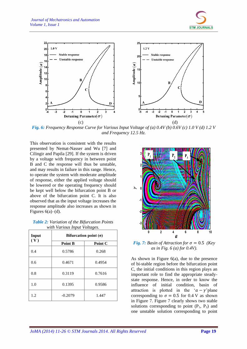
Fig. 6: Frequency Response Curve for Various Input Voltage of (a) 0.4V (b) 0.6V (c) 1.0 V (d) 1.2 V
and Frequency 12.5 Hz.
This observation is consistent with the results
presented by Nemat-Nasser and Wu [7] and
Cilingir and Papila [29]. If the system is driven
by a voltage with frequency in between point
B and C the response will thus be unstable,
and may results in failure in this range. Hence,
to operate the system with moderate amplitude
of response, either the applied voltage should
be lowered or the operating frequency should
be kept well below the bifurcation point B or
above of the bifurcation point C. It is also
observed that as the input voltage increases the
response amplitude also increases as shown in
Figures 6(a)–(d).
Table 2: Variation of the Bifurcation Points
with Various Input Voltages.
Input
( V )
Bifurcation point (σ)
Point B Point C
0.4 0.5786 0.268
0.6 0.4671 0.4954
0.8 0.3119 0.7616
1.0 0.1395 0.9586
1.2 -0.2079 1.447
Fig. 7: Basin of Attraction for (Key
as in Fig. 6 (a) for 0.4V).
As shown in Figure 6(a), due to the presence
of bi-stable region before the bifurcation point
C, the initial conditions in this region plays an
important role to find the appropriate steady-
state response. Hence, in order to know the
influence of initial condition, basin of
attraction is plotted in the ‘ ’plane
corresponding to for 0.4 V as shown
in Figure 7. Figure 7 clearly shows two stable
solutions corresponding to point (P1, P3) and
one unstable solution corresponding to point
Non-linear Vibration Response of an IPMC Actuator Biswal et al.
JoMA (2014) 11-26 © STM Journals 2014. All Rights Reserved Page 20
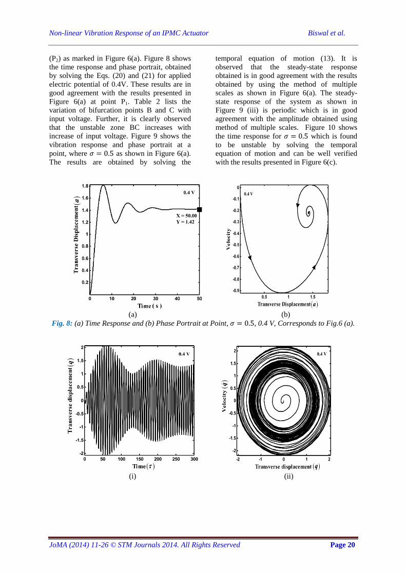
(P2) as marked in Figure 6(a). Figure 8 shows
the time response and phase portrait, obtained
by solving the Eqs. (20) and (21) for applied
electric potential of 0.4V. These results are in
good agreement with the results presented in
Figure 6(a) at point P1. Table 2 lists the
variation of bifurcation points B and C with
input voltage. Further, it is clearly observed
that the unstable zone BC increases with
increase of input voltage. Figure 9 shows the
vibration response and phase portrait at a
point, where as shown in Figure 6(a).
The results are obtained by solving the
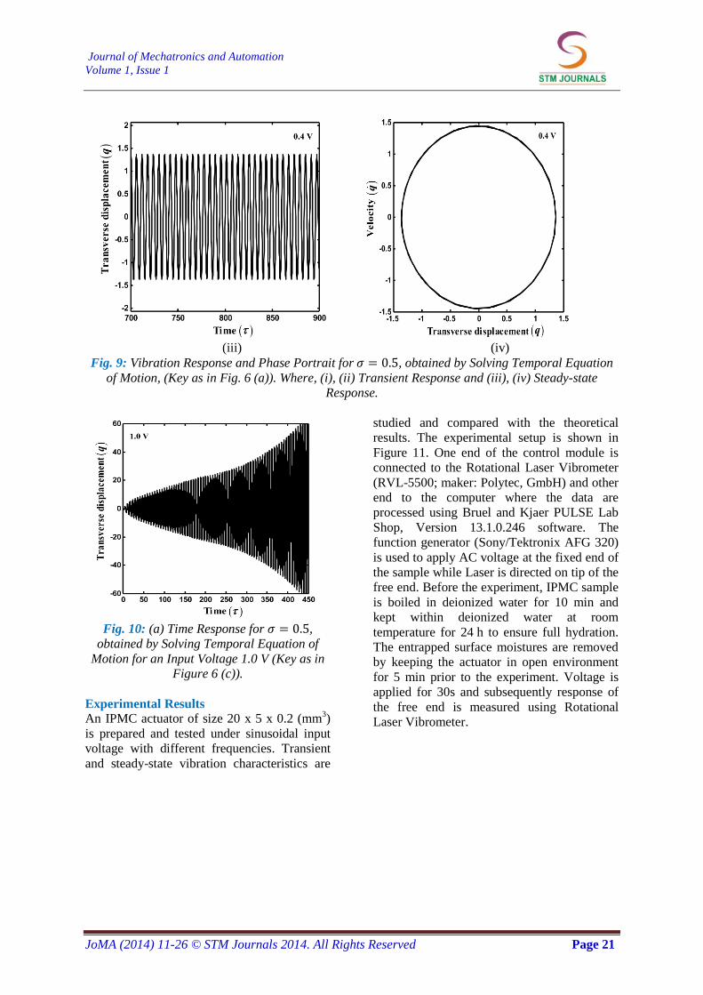
temporal equation of motion (13). It is
observed that the steady-state response
obtained is in good agreement with the results
obtained by using the method of multiple
scales as shown in Figure 6(a). The steady-
state response of the system as shown in
Figure 9 (iii) is periodic which is in good
agreement with the amplitude obtained using
method of multiple scales. Figure 10 shows
the time response for which is found
to be unstable by solving the temporal
equation of motion and can be well verified
with the results presented in Figure 6(c).
(a) (b)
Fig. 8: (a) Time Response and (b) Phase Portrait at Point, , 0.4 V, Corresponds to Fig.6 (a).
(i) (ii)
Journal of Mechatronics and Automation
Volume 1, Issue 1
JoMA (2014) 11-26 © STM Journals 2014. All Rights Reserved Page 21
(iii) (iv)
Fig. 9: Vibration Response and Phase Portrait for , obtained by Solving Temporal Equation
of Motion, (Key as in Fig. 6 (a)). Where, (i), (ii) Transient Response and (iii), (iv) Steady-state
Response.
Fig. 10: (a) Time Response for ,
obtained by Solving Temporal Equation of
Motion for an Input Voltage 1.0 V (Key as in
Figure 6 (c)).
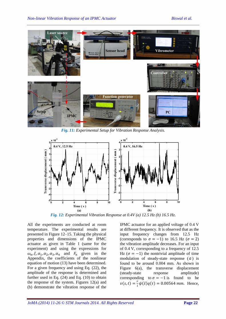
Experimental Results
An IPMC actuator of size 20 x 5 x 0.2 (mm3)
is prepared and tested under sinusoidal input
voltage with different frequencies. Transient
and steady-state vibration characteristics are
studied and compared with the theoretical
results. The experimental setup is shown in
Figure 11. One end of the control module is
connected to the Rotational Laser Vibrometer
(RVL-5500; maker: Polytec, GmbH) and other
end to the computer where the data are
processed using Bruel and Kjaer PULSE Lab
Shop, Version 13.1.0.246 software. The
function generator (Sony/Tektronix AFG 320)
is used to apply AC voltage at the fixed end of
the sample while Laser is directed on tip of the
free end. Before the experiment, IPMC sample
is boiled in deionized water for 10 min and
kept within deionized water at room
temperature for 24 h to ensure full hydration.
The entrapped surface moistures are removed
by keeping the actuator in open environment
for 5 min prior to the experiment. Voltage is
applied for 30s and subsequently response of
the free end is measured using Rotational
Laser Vibrometer.
Non-linear Vibration Response of an IPMC Actuator Biswal et al.
JoMA (2014) 11-26 © STM Journals 2014. All Rights Reserved Page 22
Fig. 11: Experimental Setup for Vibration Response Analysis.
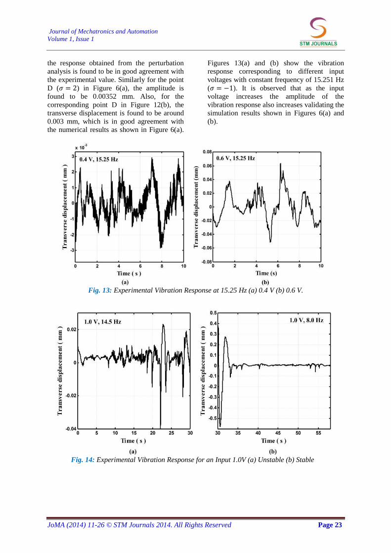
Fig. 12: Experimental Vibration Response at 0.4V (a) 12.5 Hz (b) 16.5 Hz.
All the experiments are conducted at room
temperature. The experimental results are
presented in Figure 12–15. Taking the physical
properties and dimensions of the IPMC
actuator as given in Table 1 (same for the
experiment) and using the expressions for
and given in the
Appendix, the coefficients of the nonlinear
equation of motion (13) have been determined.
For a given frequency and using Eq. (22), the
amplitude of the response is determined and
further used in Eq. (24) and Eq. (10) to obtain
the response of the system. Figures 12(a) and
(b) demonstrate the vibration response of the
IPMC actuator for an applied voltage of 0.4 V
at different frequency. It is observed that as the
input frequency changes from 12.5 Hz
(corresponds to ) to 16.5 Hz ( )
the vibration amplitude decreases. For an input
of 0.4 V, corresponding to a frequency of 12.5
Hz ( ) the nontrivial amplitude of time
modulation of steady-state response ( a ) is
found to be around 0.004 mm. As shown in
Figure 6(a), the transverse displacement
(steady-state response amplitude)
corresponding to is found to be
( )
( ) ( ) . Hence,
Journal of Mechatronics and Automation
Volume 1, Issue 1
JoMA (2014) 11-26 © STM Journals 2014. All Rights Reserved Page 23
the response obtained from the perturbation
analysis is found to be in good agreement with
the experimental value. Similarly for the point
D ( ) in Figure 6(a), the amplitude is
found to be 0.00352 mm. Also, for the
corresponding point D in Figure 12(b), the
transverse displacement is found to be around
0.003 mm, which is in good agreement with
the numerical results as shown in Figure 6(a).
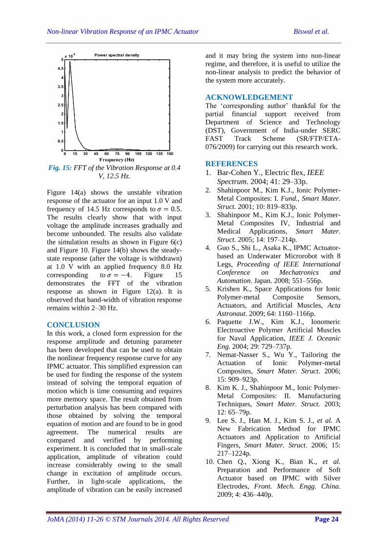
Figures 13(a) and (b) show the vibration
response corresponding to different input
voltages with constant frequency of 15.251 Hz
( ). It is observed that as the input
voltage increases the amplitude of the
vibration response also increases validating the
simulation results shown in Figures 6(a) and
(b).
Fig. 13: Experimental Vibration Response at 15.25 Hz (a) 0.4 V (b) 0.6 V.
Fig. 14: Experimental Vibration Response for an Input 1.0V (a) Unstable (b) Stable
Non-linear Vibration Response of an IPMC Actuator Biswal et al.
JoMA (2014) 11-26 © STM Journals 2014. All Rights Reserved Page 24
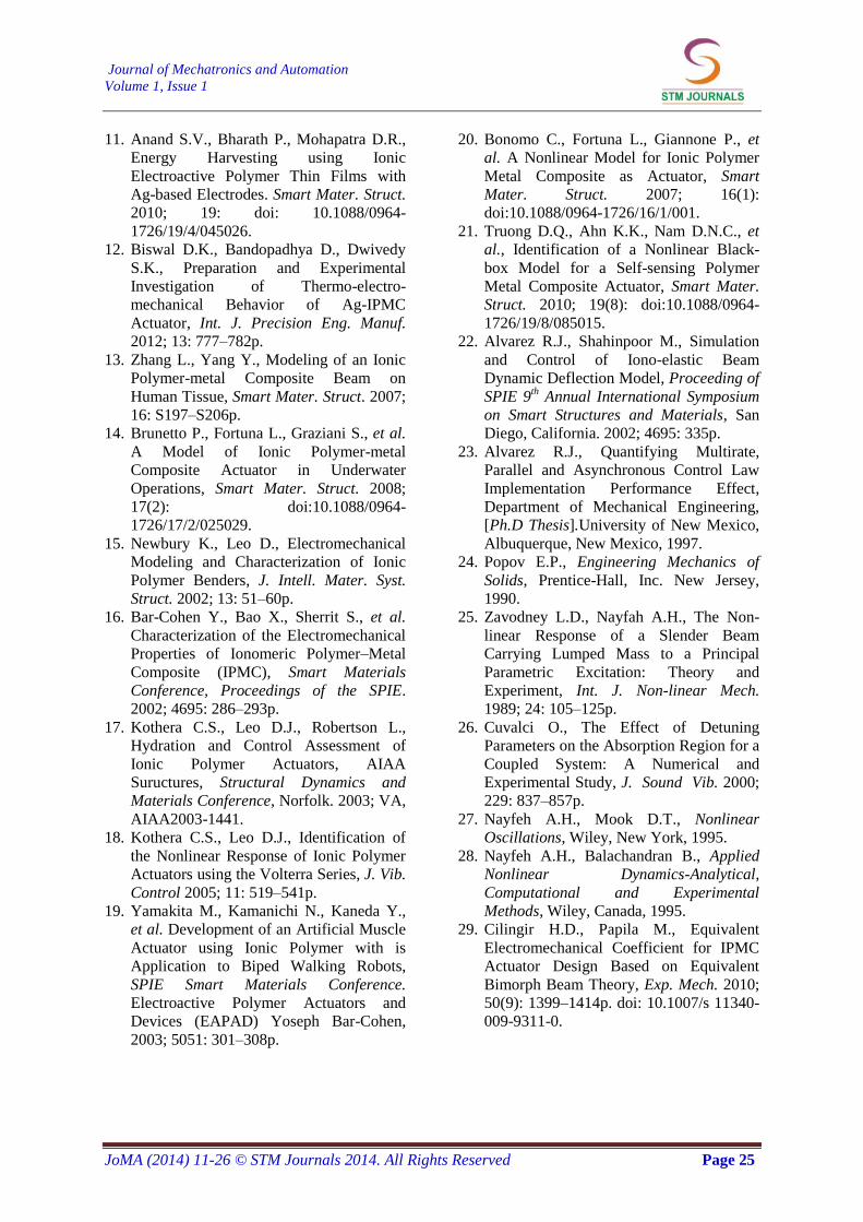
Fig. 15: FFT of the Vibration Response at 0.4
V, 12.5 Hz.
Figure 14(a) shows the unstable vibration
response of the actuator for an input 1.0 V and
frequency of 14.5 Hz corresponds to .
The results clearly show that with input
voltage the amplitude increases gradually and
become unbounded. The results also validate
the simulation results as shown in Figure 6(c)
and Figure 10. Figure 14(b) shows the steady-
state response (after the voltage is withdrawn)
at 1.0 V with an applied frequency 8.0 Hz
corresponding to . Figure 15
demonstrates the FFT of the vibration
response as shown in Figure 12(a). It is
observed that band-width of vibration response
remains within 2–30 Hz.
CONCLUSION In this work, a closed form expression for the
response amplitude and detuning parameter
has been developed that can be used to obtain
the nonlinear frequency response curve for any
IPMC actuator. This simplified expression can
be used for finding the response of the system
instead of solving the temporal equation of
motion which is time consuming and requires
more memory space. The result obtained from
perturbation analysis has been compared with
those obtained by solving the temporal
equation of motion and are found to be in good
agreement. The numerical results are
compared and verified by performing
experiment. It is concluded that in small-scale
application, amplitude of vibration could
increase considerably owing to the small
change in excitation of amplitude occurs.
Further, in light-scale applications, the
amplitude of vibration can be easily increased
and it may bring the system into non-linear
regime, and therefore, it is useful to utilize the
non-linear analysis to predict the behavior of
the system more accurately.
ACKNOWLEDGEMENT The ‘corresponding author’ thankful for the
partial financial support received from
Department of Science and Technology
(DST), Government of India-under SERC
FAST Track Scheme (SR/FTP/ETA-
076/2009) for carrying out this research work.
REFERENCES
1. Bar-Cohen Y., Electric flex, IEEE
Spectrum. 2004; 41: 29–33p. 2. Shahinpoor M., Kim K.J., Ionic Polymer-
Metal Composites: I. Fund., Smart Mater.
Struct. 2001; 10: 819–833p.
3. Shahinpoor M., Kim K.J., Ionic Polymer-
Metal Composites IV, Industrial and
Medical Applications, Smart Mater.
Struct. 2005; 14: 197–214p.
4. Guo S., Shi L., Asaka K., IPMC Actuator-
based an Underwater Microrobot with 8
Legs, Proceeding of IEEE International
Conference on Mechatronics and
Automation. Japan. 2008; 551–556p.
5. Krishen K., Space Applications for Ionic
Polymer-metal Composite Sensors,
Actuators, and Artificial Muscles, Acta
Astronaut. 2009; 64: 1160–1166p.
6. Paquette J.W., Kim K.J., Ionomeric
Electroactive Polymer Artificial Muscles
for Naval Application, IEEE J. Oceanic
Eng. 2004; 29: 729–737p.
7. Nemat-Nasser S., Wu Y., Tailoring the
Actuation of Ionic Polymer-metal
Composites, Smart Mater. Struct. 2006;
15: 909–923p.
8. Kim K. J., Shahinpoor M., Ionic Polymer-
Metal Composites: II. Manufacturing
Techniques, Smart Mater. Struct. 2003;
12: 65–79p.
9. Lee S. J., Han M. J., Kim S. J., et al. A
New Fabrication Method for IPMC
Actuators and Application to Artificial
Fingers, Smart Mater. Struct. 2006; 15:
217–1224p.
10. Chen Q., Xiong K., Bian K., et al.
Preparation and Performance of Soft
Actuator based on IPMC with Silver
Electrodes, Front. Mech. Engg. China.
2009; 4: 436–440p.
Journal of Mechatronics and Automation
Volume 1, Issue 1
JoMA (2014) 11-26 © STM Journals 2014. All Rights Reserved Page 25
11. Anand S.V., Bharath P., Mohapatra D.R.,
Energy Harvesting using Ionic
Electroactive Polymer Thin Films with
Ag-based Electrodes. Smart Mater. Struct.
2010; 19: doi: 10.1088/0964-
1726/19/4/045026.
12. Biswal D.K., Bandopadhya D., Dwivedy
S.K., Preparation and Experimental
Investigation of Thermo-electro-
mechanical Behavior of Ag-IPMC
Actuator, Int. J. Precision Eng. Manuf.
2012; 13: 777–782p.
13. Zhang L., Yang Y., Modeling of an Ionic
Polymer-metal Composite Beam on
Human Tissue, Smart Mater. Struct. 2007;
16: S197–S206p.
14. Brunetto P., Fortuna L., Graziani S., et al.
A Model of Ionic Polymer-metal
Composite Actuator in Underwater
Operations, Smart Mater. Struct. 2008;
17(2): doi:10.1088/0964-
1726/17/2/025029.
15. Newbury K., Leo D., Electromechanical
Modeling and Characterization of Ionic
Polymer Benders, J. Intell. Mater. Syst.
Struct. 2002; 13: 51–60p.
16. Bar-Cohen Y., Bao X., Sherrit S., et al.
Characterization of the Electromechanical
Properties of Ionomeric Polymer–Metal
Composite (IPMC), Smart Materials
Conference, Proceedings of the SPIE.
2002; 4695: 286–293p.
17. Kothera C.S., Leo D.J., Robertson L.,
Hydration and Control Assessment of
Ionic Polymer Actuators, AIAA
Suructures, Structural Dynamics and
Materials Conference, Norfolk. 2003; VA,
AIAA2003-1441.
18. Kothera C.S., Leo D.J., Identification of
the Nonlinear Response of Ionic Polymer
Actuators using the Volterra Series, J. Vib.
Control 2005; 11: 519–541p.
19. Yamakita M., Kamanichi N., Kaneda Y.,
et al. Development of an Artificial Muscle
Actuator using Ionic Polymer with is
Application to Biped Walking Robots,
SPIE Smart Materials Conference.
Electroactive Polymer Actuators and
Devices (EAPAD) Yoseph Bar-Cohen,
2003; 5051: 301–308p.
20. Bonomo C., Fortuna L., Giannone P., et
al. A Nonlinear Model for Ionic Polymer
Metal Composite as Actuator, Smart
Mater. Struct. 2007; 16(1):
doi:10.1088/0964-1726/16/1/001.
21. Truong D.Q., Ahn K.K., Nam D.N.C., et
al., Identification of a Nonlinear Black-
box Model for a Self-sensing Polymer
Metal Composite Actuator, Smart Mater.
Struct. 2010; 19(8): doi:10.1088/0964-
1726/19/8/085015.
22. Alvarez R.J., Shahinpoor M., Simulation
and Control of Iono-elastic Beam
Dynamic Deflection Model, Proceeding of
SPIE 9th Annual International Symposium
on Smart Structures and Materials, San
Diego, California. 2002; 4695: 335p.
23. Alvarez R.J., Quantifying Multirate,
Parallel and Asynchronous Control Law
Implementation Performance Effect,
Department of Mechanical Engineering,
[Ph.D Thesis].University of New Mexico,
Albuquerque, New Mexico, 1997.
24. Popov E.P., Engineering Mechanics of
Solids, Prentice-Hall, Inc. New Jersey,
1990.
25. Zavodney L.D., Nayfah A.H., The Non-
linear Response of a Slender Beam
Carrying Lumped Mass to a Principal
Parametric Excitation: Theory and
Experiment, Int. J. Non-linear Mech.
1989; 24: 105–125p.
26. Cuvalci O., The Effect of Detuning
Parameters on the Absorption Region for a
Coupled System: A Numerical and
Experimental Study, J. Sound Vib. 2000;
229: 837–857p.
27. Nayfeh A.H., Mook D.T., Nonlinear
Oscillations, Wiley, New York, 1995.
28. Nayfeh A.H., Balachandran B., Applied
Nonlinear Dynamics-Analytical,
Computational and Experimental
Methods, Wiley, Canada, 1995.
29. Cilingir H.D., Papila M., Equivalent
Electromechanical Coefficient for IPMC
Actuator Design Based on Equivalent
Bimorph Beam Theory, Exp. Mech. 2010;
50(9): 1399–1414p. doi: 10.1007/s 11340-
009-9311-0.
Non-linear Vibration Response of an IPMC Actuator Biswal et al.
JoMA (2014) 11-26 © STM Journals 2014. All Rights Reserved Page 26
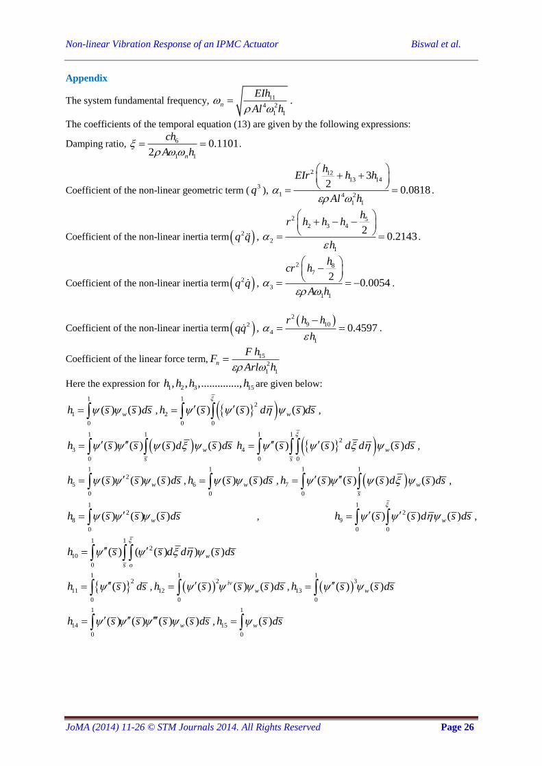
Appendix
The system fundamental frequency, 11
4 2
1 1
n
EIh
Al h
.
The coefficients of the temporal equation (13) are given by the following expressions:
Damping ratio, 6
1 1
0.11012 n
ch
A h
.
Coefficient of the non-linear geometric term (3q ),
2 1213 14
1 4 2
1 1
32
0.0818
hEIr h h
Al h
.
Coefficient of the non-linear inertia term 2q q ,
2 52 3 4
2
1
20.2143
hr h h h
h
.
Coefficient of the non-linear inertia term 2q q ,
2 87
3
1 1
20.0054
hcr h
A h
.
Coefficient of the non-linear inertia term 2qq , 2
9 10
4
1
0.4597r h h
h
.
Coefficient of the linear force term, 15
2
1 1
n
F hF
Arl h
Here the expression for 1 2 3 15, , ,..............,h h h h are given below:
1
1
0
( ) ( )wh s s ds , 1
2
2
0 0
( ) ( ) ( )wh s s d s ds
,
1 1
3
0
( ) ( ) ( ) ( )w
s
h s s s d s ds 1 1
2
4
0 0
( ) ( ) ( )w
s
h s s d d s ds
,
1
2
5
0
( ) ( ) ( )wh s s s ds ,
1
6
0
( ) ( )wh s s ds , 1 1
7
0
( ) ( ) ( ) ( )w
s
h s s s d s ds ,
1
2
8
0
( ) ( ) ( )wh s s s ds ,
1
2
9
0 0
( ) ( ) ( )wh s s d s ds
,
1 1
2
10
0
( ) ( ( ) ) ( )w
s o
h s s d d s ds
1
2
11
0
( )h s ds , 1
2
12
0
( ) ( ) ( )iv
wh s s s ds , 1
3
13
0
( ) ( )wh s s ds
1
14
0
( ) ( ) ( ) ( )wh s s s s ds ,
1
15
0
( )wh s ds
Copyright © 2022 FDOKUMEN