Development of a 2DOF micromanipulation system with IPMC actuators
6
Abstract—This paper presents the design and control of a novel 2 degree-of-freedom (2DOF) micromanipulator to facilitate the safe handling and manipulation of biological materials. The manipulator is driven by two IPMC actuators for each DOF and the system controller is adaptively tuned online using a model-free iterative feedback tuning (IFT) algorithm to adjust the controller parameters to optimize the system performance. A 2DOF controller structure was implemented for each axis of motion so both the disturbance rejection (DR) and set point (SP) response can be optimized, making the system ideal for operating in unknown environments. Simulations are presented which utilize an IPMC model and mechanical manipulator model to show the system performance has been improved by 37% for the DR and by 24% and 28% for SP in the horizontal and vertical direction respectively. Experimental results are also presented to validate the design and show the system can achieve outputs of up to 7° in both axes. I. INTRODUCTION EDICAL research is fast advancing and is having a large impact on a variety of diseases such as cancer, diabetes and neuro-degeneration as well as diseases of the cardiovascular system, lungs, blood and skeleton. In order to facilitate this research, new intelligent micro/nano devices capable of operating in biological environments for safe cell handling and manipulation are essential [1-3]. Current techniques of cell manipulation such as laser trapping, piezo-grippers, micro-tweezers etc commonly damage cell walls and membranes due to their rigidity and lack of force compliance making them inadequate for many tasks involving ‘soft’ biological materials like human cells [1, 2]. This has a major effect on the progression of scientific knowledge resulting in significant loss of research time, money and resources in addition to raising ethical issues [3]. IPMCs have intrinsic properties which make them desirable sensors and actuators, including very low mass, Manuscript received February 19, 2011. This work was supported in part by the International Investment Opportunities Fund (IIOF) from the Foundation for Research, Science and Technology (FRST) of New Zealand (Contract number: UOAX0723). A. J. McDaid is with the Department of Mechanical Engineering, The University of Auckland, Auckland NZ (phone: +64 9 373-7599 ext. 87555; fax: +64 9 373-7479; e-mail: [email protected]). K. C. Aw is with the Department of Mechanical Engineering, The University of Auckland, Auckland NZ, e-mail: [email protected]). S. Q. Xie is with the Department of Mechanical Engineering, The University of Auckland, Auckland NZ (e-mail: [email protected]). E. Haemmerle is with the Department of Mechanical Engineering, The University of Auckland, Auckland NZ (e-mail: e.haemmerle @auckland.ac.nz). custom geometries, biocompatibility, flexibility and compliance, low power consumption and the ability to accurately achieve both micro and macro deflections without any gearing or other mechanisms [4, 5]. IPMCs present a unique and smart system for cell manipulation due to their ability to work well in fluid and cellular environments as well as their natural compliance giving them a ‘soft touch’ when interacting with sensitive materials and/or in sensitive environments. Employing the soft and compliant IPMC actuators as cell and micro-organism manipulators will present a solution for safe handling and manipulation of biological cells. II. MANIPULATOR DESIGN A. Specifications For the proposed micromanipulation system to be used for a real application, a number of specifications are required, all of which had to be considered throughout the design process. These specifications, outlined below, are based on current devices and literature for the manipulation of biological cells [1, 6, 7]; 1) 2DOF axis motion; 2) high compliance and hence back-drivability to achieve a ‘soft touch’; 3) 10μm resolution; 4) 4x4mm range of motion (ROM); 5) high-level of accuracy and repeatability; 6) optimize disturbance rejection (DR) and set-point (SP) tracking response; 7) ability to accommodate any micro-tool and 8) consideration for all sensors and a microscope. B. Mechanical Mechanism Design In order to develop such a system two IPMCs are necessary to achieve the required DOF and ROM for the mechanism. Each IPMC must be clamped at one end in order to provide electrical stimulus while free to bend at the other. The force provided by the IPMC due to the input electric potential must then be transferred to the manipulation mechanism which will interact with the sample specimen through the attachment of an appropriate micro- tool. Based on this criteria and the specifications described above the final design was developed and is presented in Fig. 1. It can be seen that there are two rotating arms which convert the non-uniform bending of the IPMCs into a Development of a 2DOF Micromanipulation System with IPMC Actuators Andrew J. McDaid, Kean C. Aw, Member, IEEE, Sheng Q. Xie, Member, IEEE, and Enrico Haemmerle M 2011 IEEE/ASME International Conference on Advanced Intelligent Mechatronics (AIM2011) Budapest, Hungary, July 3-7, 2011 978-1-4577-0839-8/11/$26.00 ©2011 IEEE 518
Transcript of Development of a 2DOF micromanipulation system with IPMC actuators

Abstract—This paper presents the design and control of a novel 2 degree-of-freedom (2DOF) micromanipulator to facilitate the safe handling and manipulation of biological materials. The manipulator is driven by two IPMC actuators for each DOF and the system controller is adaptively tuned online using a model-free iterative feedback tuning (IFT) algorithm to adjust the controller parameters to optimize the system performance. A 2DOF controller structure was implemented for each axis of motion so both the disturbance rejection (DR) and set point (SP) response can be optimized, making the system ideal for operating in unknown environments. Simulations are presented which utilize an IPMC model and mechanical manipulator model to show the system performance has been improved by 37% for the DR and by 24% and 28% for SP in the horizontal and vertical direction respectively. Experimental results are also presented to validate the design and show the system can achieve outputs of up to 7° in both axes.
I. INTRODUCTION EDICAL research is fast advancing and is having a large impact on a variety of diseases such as cancer,
diabetes and neuro-degeneration as well as diseases of the cardiovascular system, lungs, blood and skeleton. In order to facilitate this research, new intelligent micro/nano devices capable of operating in biological environments for safe cell handling and manipulation are essential [1-3].
Current techniques of cell manipulation such as laser trapping, piezo-grippers, micro-tweezers etc commonly damage cell walls and membranes due to their rigidity and lack of force compliance making them inadequate for many tasks involving ‘soft’ biological materials like human cells [1, 2]. This has a major effect on the progression of scientific knowledge resulting in significant loss of research time, money and resources in addition to raising ethical issues [3].
IPMCs have intrinsic properties which make them desirable sensors and actuators, including very low mass,
Manuscript received February 19, 2011. This work was supported in part by the International Investment
Opportunities Fund (IIOF) from the Foundation for Research, Science and Technology (FRST) of New Zealand (Contract number: UOAX0723).
A. J. McDaid is with the Department of Mechanical Engineering, The University of Auckland, Auckland NZ (phone: +64 9 373-7599 ext. 87555; fax: +64 9 373-7479; e-mail: [email protected]).
K. C. Aw is with the Department of Mechanical Engineering, The University of Auckland, Auckland NZ, e-mail: [email protected]).
S. Q. Xie is with the Department of Mechanical Engineering, The University of Auckland, Auckland NZ (e-mail: [email protected]).
E. Haemmerle is with the Department of Mechanical Engineering, The University of Auckland, Auckland NZ (e-mail: e.haemmerle @auckland.ac.nz).
custom geometries, biocompatibility, flexibility and compliance, low power consumption and the ability to accurately achieve both micro and macro deflections without any gearing or other mechanisms [4, 5]. IPMCs present a unique and smart system for cell manipulation due to their ability to work well in fluid and cellular environments as well as their natural compliance giving them a ‘soft touch’ when interacting with sensitive materials and/or in sensitive environments. Employing the soft and compliant IPMC actuators as cell and micro-organism manipulators will present a solution for safe handling and manipulation of biological cells.
II. MANIPULATOR DESIGN
A. Specifications For the proposed micromanipulation system to be used for
a real application, a number of specifications are required, all of which had to be considered throughout the design process. These specifications, outlined below, are based on current devices and literature for the manipulation of biological cells [1, 6, 7];
1) 2DOF axis motion; 2) high compliance and hence back-drivability to
achieve a ‘soft touch’; 3) 10µm resolution; 4) 4x4mm range of motion (ROM); 5) high-level of accuracy and repeatability; 6) optimize disturbance rejection (DR) and set-point
(SP) tracking response; 7) ability to accommodate any micro-tool and 8) consideration for all sensors and a microscope.
B. Mechanical Mechanism Design In order to develop such a system two IPMCs are
necessary to achieve the required DOF and ROM for the mechanism. Each IPMC must be clamped at one end in order to provide electrical stimulus while free to bend at the other. The force provided by the IPMC due to the input electric potential must then be transferred to the manipulation mechanism which will interact with the sample specimen through the attachment of an appropriate micro-tool.
Based on this criteria and the specifications described above the final design was developed and is presented in Fig. 1. It can be seen that there are two rotating arms which convert the non-uniform bending of the IPMCs into a
Development of a 2DOF Micromanipulation System with IPMC Actuators
Andrew J. McDaid, Kean C. Aw, Member, IEEE, Sheng Q. Xie, Member, IEEE, and Enrico Haemmerle
M
2011 IEEE/ASME International Conference onAdvanced Intelligent Mechatronics (AIM2011)Budapest, Hungary, July 3-7, 2011
978-1-4577-0839-8/11/$26.00 ©2011 IEEE 518

uniform rotational path by using slots for the IPMC tip to freely slide in. This mechanism gives a more consistent and hence robust motion while adding minimal frictional losses and backlash to the system. IPMC #1 is working horizontally and hence does not have to overcome gravity, while the arm for IPMC #2 has been counter balanced to ensure that despite acting in the vertical direction the gravitational effect will be minimal.
Two laser displacement sensors will be used for the 2DOF as shown in Fig. 1 (b) and (c). A microscope can easily be placed under the transparent worktable in order to provide visual feedback for the user as shown in Fig. 1 (c). The worktable can also be adjusted up and down in the vertical direction to accommodate different samples.
The two arms can be designed to whatever dimensions are required to accommodate any particular IPMCs (as IPMCs can be fabricated to any geometry) for the specific application requirements, i.e. force, displacement etc. This gives a huge flexibility to this manipulator design.
The manipulator was designed in Pro/ENGINEER and then a mathematical model was developed in MATLAB Simulink. The mathematical model describes the mechanical dynamics of the mechanism fully, including joint friction, so accurate simulations can be undertaken.
C. IPMC Actuator As IPMCs can be fabricated to any geometry, any size
actuator could be used for the system depending on the performance requirements. In this project we had available a 55x20mm, 800µm thick IPMC sheet, from Environmental Robots Inc based on an XR resin, with Pt electrodes. This sheet was therefore the amount of material we had to cut two IPMC strips from. A simulation was needed to decide the dimensions of the IPMC to be used in the manipulator.
D. IPMC Model The IPMC model which will be used to simulate and
verify the manipulator before building it was first proposed by McDaid et al. in [8]. This is a nonlinear scalable model so it is extremely useful in any mechanical design process such as for this manipulator as different sized actuators can be tested to measure the performance before the system is built. The material parameters in the model were updated for the new IPMC material that was to be used.
The model does accurately represent the IPMC response at the time of experimentation, but over a period of operation the highly time-varying nature of the IPMC will cause the response to change unpredictably. This cannot be modeled as the variance is due to ion redistribution which is a stochastic process. As such the simulations will give indication of the system performance but it can be expected that the experimental results may vary from the simulation results. This also indicates that although model-based controller tuning may give good system performance at the time of modeling, it cannot guarantee this performance at some later stage of the systems operation. This is the motivation for the using an online automatic tuning algorithm for intelligently controlling the manipulator.
E. Manipulator Simulation and Verification The manipulator motion is in the rotational coordinate
system and therefore the resolution and ROM are dependent on the distance of the tip of the micro-tool to the centre of rotation (COR) of the two arms. For this particular design the micro-tool tip will be 20mm from the COR, this is because the laser sensors, which have a 10µm resolution, will be positioned >20mm from the COR so therefore the resolution specification is met.
The manipulator system was simulated for a number of different sized IPMCs with the complete IPMC and manipulator mechanical model and it was found that a size of 27.5mm long by 10mm wide would give good results for the ROM and available force output as well as making the best use of the available sheet of IPMC. Open loop simulations of the manipulator system reveal that up to 8.6° can be achieved in both axis, which is well above the 5.7° required meet the ROM specifications. Fig. 2 below shows an open loop simulation of the two axis motion with an out of phase 3V pulsed input. A number of different resolutions, ROMs and forces can be achieved by using micro-tools with different lengths.
(a)
(b) (c)
Fig. 1. (a) 3D, (b) top and (c) side view of the micromanipulation system
519

III. CONTROL SYSTEM An advanced control system is required to ensure that the
system can perform accurately in a complex and unknown environment and when interacting with sensitive biological materials. Also the IPMC actuators themselves are highly non-linear and time-varying so this presents a major control problem which requires an adaptive control algorithm to be employed [4].
A. Iterative Feedback Tuning (IFT) IFT is a model-free approach which adaptively optimizes
a system response by tuning the controller parameters of a system based solely on experimental data from the system itself [9, 10]. As the IFT algorithm has no requirements of any model or knowledge of the system it is ideal for operating in complex and sensitive environments and also accounting for the variability and drift of the IPMC dynamics over a period of operation. IFT will ensure that the manipulator remains accurate and repeatable throughout all experiments; this is an essential specification in cell manipulation.
B. 2DOF Control Structure The system will be operating in an unknown environment
where there is inevitably a large amount of external noise and disturbance introduced to the system as well as electronic and mechanical-thermal noises which are very common in MEMS actuators. As such the adaptive control
scheme must seek to improve the DR of the IPMC in an unknown environment as well as providing accurate tracking of a desired SP in order for the manipulator to successfully carry out its tasks.
To realize this a 2DOF control structure shown in Fig. 3 will be implemented which will permit optimal performance under both DR criteria (rejecting all external disturbances, d(t)) and SP criteria (optimal when the output, y(t), follows the reference input, r(t), exactly) where a traditional 1DOF controller has to either be tuned for the DR or SP separately and cannot be optimized for both simultaneously [11].
The 2DOF structure has two regulators Gc and Gf, with tunable parameters ρc and ρf respectively, which determine the response of the system by controlling the input voltage, u(t), to the plant, GIPMC. Hs represents the sensor dynamics and a low pass filter which is used to reject the high frequency measurement noise, dm(t).
The closed loop transfer functions from r(t) and d(t) to y(t) is given by (1) and (2) respectively.
1
(1)
11
(2)
From this it is easy to see that the DR has no effect from Gf and as such the parameters ρc can be optimal tuned separately from the SP. The SP can then be tuned by fixing the parameters ρc and adjusting ρf. In this way both the DR and SP are optimized. Note however that this method does not necessarily guarantee the global optimal if for instance the poles of the system that are determined at the first step are too extreme only a poor set point response may be possible [11]. In this research the two step tuning has proved to be extremely effective for optimizing both the DR and SP as seen in the results section.
It was decided that the regulator in series, Gc would have proportional, integral and derivative elements, (3), while the feed forward regulator, Gf would only have proportional and derivative action, (4). This design choice will ensure the steady state error, e(t), goes to zero robustly for step inputs of d(t) and r(t) [11].
(3)
(4)
(a)
(b)
(c)
Fig. 2. Open-loop simulation results for (a) horizontal, (b) vertical and (c) end effector path.
Fig. 3. 2DOF control system
0 50 100 150 200-5
0
5
Time, (s)
θ 1,
(o) /
(V)
y(t) Voltage
0 50 100 150 200-5
0
5
Time, (s)
θ 2,
(o) /
(V)
y(t) Voltage
-5 0 5-5
0
5
θ 1, (o)
θ 2,
(o)
520
C. IFT Theory for 2DOF Control Structure The IFT algorithm is a time domain approach which seeks
to minimize a design criterion of the system. There have been a number of different design criteria proposed in the literature which are variations on output error and control effort with different filters to place more emphasis on a certain feature of the response, for example overshoot, transients or some important frequency range. These filters have been found to work well but usually at the expense of other features of the system.
The specifications for the manipulator state that the system must be highly accurate and repeatable for all commands in DR and SP and therefore it was determined that a quadratic function based on a standard least squares fit of the tracking error, , as shown below in (5) would give the best overall response.
(5)
where ρ is the vector of the controller parameters to be
tuned, N is the total number of time steps for a given
experiment and is the system error at discrete time step t. The premise of the IFT algorithm is to find a minimum of the design criteria, J, in this case finding the minimum tracking error over the entire experiment.
The minimum of the criteria is found using a gradient search algorithm. The gradient of the criteria is found by differentiating (5) and the minimum of the criteria is found when this is equal to 0, (6).
(6)
Experiments are undertaken on the system to find at any point in time. Then (6) can be solved using the iterative algorithm, (7) (gradient search) to find ρ which will yield the minimum error for the system,
(7)
where Ri is an appropriate positive definite matrix which
determines the search direction for the optimization, i is the iteration number and γ is a positive real scalar which controls the step size. Using the identity matrix for Ri gives a negative gradient direction. It is commonly accepted in the literature [9, 12, 13] that using the Gauss-Newton approximation of the Hessian of J(ρ) for Ri gives improved results.
The two step tuning procedure as described in the previous section is undertaken using IFT to first optimize the DR of the IPMC and then the SP tracking of the
manipulator. In order to tune for DR a repeatable mechanical disturbance must be injected at the same time in each experiment. The most accurately way to carry this out practically is to inject the disturbance on to the IPMC separately, without the mechanism. This then implies that the IPMC itself is tuned for DR and when integrated into the mechanism the load applied by the mechanism is treated as a disturbance on to the IPMC. This can be justified as the manipulator dynamics adds very little load onto the IPMC, in both the horizontal and vertical direction. The disturbance loads will be due to inertia, coriolis effect, gravity and friction of the manipulator. Gravity compensation has been implemented, also the mass and velocities are extremely low causing the inertia, coriolis torque to be low as well as the friction, which is dependent on the normal reaction force. Next the actuators are put into the mechanical system and the manipulator is tuned for SP in each axis of motion. The system will now exhibit good DR from the mechanism loads, environmental effects and loads due to objects being manipulated as well as good SP so the entire mechanism can accurately track a desired reference input.
IV. RESULTS
A. Simulation The full model of the system which was developed by
integrating the IPMC actuator model and the mechanical model of the mechanism was used to simulate the system response and validate the entire design with control system.
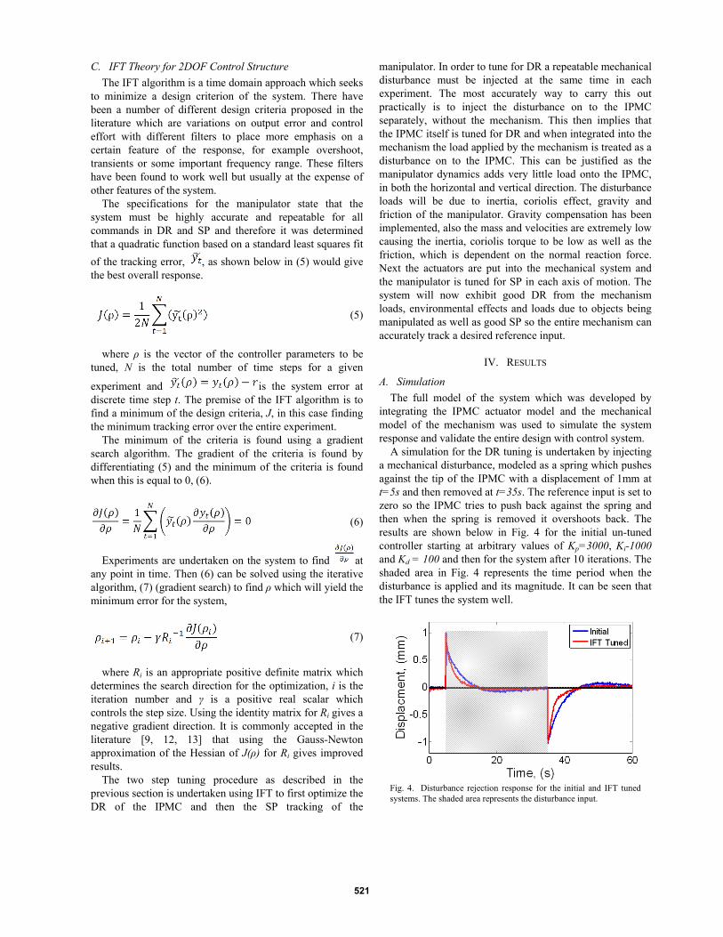
A simulation for the DR tuning is undertaken by injecting a mechanical disturbance, modeled as a spring which pushes against the tip of the IPMC with a displacement of 1mm at t=5s and then removed at t=35s. The reference input is set to zero so the IPMC tries to push back against the spring and then when the spring is removed it overshoots back. The results are shown below in Fig. 4 for the initial un-tuned controller starting at arbitrary values of Kp=3000, Ki-1000 and Kd = 100 and then for the system after 10 iterations. The shaded area in Fig. 4 represents the time period when the disturbance is applied and its magnitude. It can be seen that the IFT tunes the system well.
Fig. 4. Disturbance rejection response for the initial and IFT tuned systems. The shaded area represents the disturbance input.
521

Fig. 5 (a) shows the cost function, J, for the DR tuning
and it can be seen that the IFT algorithm does improve the DR by 37% over the 10 iterations. Fig. 5 (b) shows the adjustment of the controller gains over the same 10 iterations.
The results for the controller gains , ρc, are then fixed and the IFT algorithm is then setup to tune the manipulator system with integrated IPMCs for SP. The reference input is set to be 1° for 15s, then back to zero for the next 15s, then to -1° for 15s and then back to zero for the last 15s of the experiment. The results for the tuning the horizontal axis, θ1, are shown below in Fig. 6 (a) and for the vertical axis in Fig. 6 (b). It can be seen that the IFT does improve the system response for the SP for both axis.
Fig. 7 (a) and (b) show the cost functions for the horizontal and vertical motions respectively through the tuning process. It is clear that the IFT is improving the performance in both directions and after 10 iterations the system has improved by 24% in the horizontal and 28% in the vertical direction. Fig. 7 (c) and (d) shows the adjustment of the 2DOF controller gains, α and β, for the horizontal and vertical motions, respectively over the 10 iterations.
The system has been validated so the manipulator was then built and experimental work was undertaken next.
B. Experiment The manipulator was rapid prototyped using ABS material
as shown in Fig 8. The IPMCs are mounted and the system is then tested.
(a)
(b)
Fig. 5. (a) Cost function and (b) controller gain updates for 10 iterations of DR tuning.
(a)
(b)
Fig. 6. SP response for the initial and IFT tuned systems for (a) horizontal and (b) vertical direction.
(a) (b)
(c) (d) Fig. 7. Cost function in the (a) horizontal and (b) vertical directions and controller gain updates for the (c) horizontal and (d) vertical directions for 10 iterations of SP tuning.
Fig. 8. Manipulation system with IPMCs and micro-probe.
0 2 4 6 8 101.5
2
2.5
3 x 10⁻⁸
Iteration Number, i
Cos
t Fun
ctio
n, J
0 2 4 6 8 100
2000
4000
6000
Iteration Number, i
Con
trol P
aram
eter
s
KpKiKd
0 10 20 30 40 50 60-1.5
-1
-0.5
0
0.5
1
1.5
Time, (s)
Angl
e, (o
)
r(t)InitialIFT Tuned
0 10 20 30 40 50 60-1.5
-1
-0.5
0
0.5
1
1.5
Time, (s)
Angl
e, (o
)
r(t)InitialIFT Tuned
0 2 4 6 8 108
9
10
11 x 10-9
Iteration Number, i
Cos
t Fun
ctio
n, J
0 2 4 6 8 101.2
1.4
1.6
1.8 x 10⁻⁸
Iteration Number, i
Cos
t Fun
ctio
n, J
0 2 4 6 8 10-2000
0
2000
4000
6000
Iteration Number, i
Con
trol P
aram
eter
s
αβ
0 2 4 6 8 10-1000
0
1000
2000
3000
Iteration Number, iC
ontro
l Par
amet
ers
αβ
522

The experimental results for the tracking response are shown below in Fig. 9. where a step of 0.5° was input as the reference in both directions every 25s. It can be seen that the manipulator does track the reference well in both degrees of freedom.
V. DISCUSSION The manipulator system has been developed to
successfully meet all the required specifications as laid out in Section II. This was achieved by carrying out a thorough design process, from first developing a design based model for the IPMC, then designing a novel 2DOF mechanism, carrying out simulations in order to tweak the design so that it does exhibit good performance before finally building an verifying the design in real life. This manipulator design is, to the best of our knowledge, the first example of utilizing IPMCs to actuate an external mechanical mechanism to achieve an output in 2DOF. This research also demonstrates that going through a thorough design process when developing systems with integrated IPMCs is a very useful task in order to optimize the systems performance.
The manipulator has been designed to have inherent compliance through the IPMCs themselves, this adds some passive safety to the design, for example if the controller causes the micro-tool to overshoot, the cells may still avoid harm where other rigid systems will certainly damage the cells. Despite this the manipulator can still cause damage as it is only controlled with positional feedback so if for example there is a variation in the environment and the tool comes into contact with a cell unexpectedly the position error will drive the tool to keep moving and hence cause damage to the cell. This can be avoided by lengthening the micro-tool to reduce the available force that can be exerted (lever concept) so it is below a level which can damage a cell. In this way if there is any unplanned contact, the manipulator cannot provide enough force to harm the cell.
The manipulator has demonstrated that it does operate well as a positioning system, with the ability to be robust against any external disturbances which will be encountered when interacting during cell manipulation. Although the system has been designed to be robust in its operation, it is not sufficient to have only position control for extremely sensitive procedures and hence is very important to have
force feedback during experiments to ensure safe handling of the cells. With force information impedance control and ‘fail-safe’ measures can be employed to develop a truly safe system which has both active and passive safety measures.
Further work is currently being undertaken to fully characterize all the performance characteristics and hence verify that the manipulation system fully meets all the specifications. Also force control will be the next step to enable impedance control of the device which will be essential when interacting in the sensitive environments.
VI. CONCLUSIONS A 2DOF micromanipulation system which can be used for
the safe handling of sensitive biological materials, due to the inherent compliance of the IPMC actuators, has been developed and implemented. The system was first designed in simulation to refine the performance before implementing the system for real application. A 2DOF controller which is adaptively tuned using an IFT algorithm has been successfully employed to optimize the system performance in both the DR and SP response. Experiments have validated that the manipulator system has meet all the desired specifications.
REFERENCES
[1] T. Yih and I. E. Talpasanu, Micro and Nano Manipulations for Biomedical Applications. Boston: Artech House, Inc, 2008.
[2] K. Inoue, et al., "Micro-manipulation system with a two-fingered micro-hand and its potential application in bioscience," Journal of Biotechnology, vol. 133, pp. 219-224, 2008.
[3] B. Asiyanbola and W. Soboyejo, "For the Surgeon: An Introduction to Nanotechnology," Journal of Surgical Education, vol. 65, pp. 155-161.
[4] A. J. McDaid, et al., "Gain scheduled control of IPMC actuators with `model-free' iterative feedback tuning," Sensors and Actuators A: Physical, vol. 164, pp. 137-147, 2010.
[5] M. Shahinpoor and K. J. Kim, "Ionic polymer-metal composites: I. Fundamentals," Smart Materials and Structures, vol. 10, pp. 819-833, 2001.
[6] K. Deok-Ho, et al., "Mechanical force response of single living cells using a microrobotic system," in Robotics and Automation, 2004. Proceedings. ICRA '04. 2004 IEEE International Conference on, 2004, pp. 5013-5018 Vol.5.
[7] L. Zhe and et al., "A micromanipulation system with dynamic force-feedback for automatic batch microinjection," Journal of Micromechanics and Microengineering, vol. 17, p. 314, 2007.
[8] A. J. McDaid, et al., "A conclusive scalable model for the complete actuation response for IPMC transducers," Smart Materials and Structures, vol. 19, p. 075011, 2010.
[9] H. Hjalmarsson, "Iterative feedback tuning - an overview," International Journal of Adaptive Control and Signal Processing, vol. 16, pp. 373-395, 2002.
[10] H. Hjalmarsson, et al., "A convergent iterative restricted complexity control design scheme," in Decision and Control, 1994., Proceedings of the 33rd IEEE Conference on, 1994, pp. 1735-1740.
[11] M. Araki and H. Taguchi, "Two-Degree-of-Freedom PID Controllers," International Journal of Control, Automation and Systems, vol. 1, pp. 401-411, 2003.
[12] H. Hjalmarsson, et al., "Iterative feedback tuning-theory and applications," IEEE Control Systems, vol. 26, p. 41, 1998.
[13] A. E. Graham, et al., "Rapid tuning of controllers by IFT for profile cutting machines," Mechatronics, vol. 17, pp. 121-128, 2007.
Fig. 9. Experimental SP tracking in 2DOF
0 2 4 6 80
2
4
6
8
θ 1, (o)
θ 2,
(o)
Manipulator PathTargets
523