Modeling, fabrication, and validation of a high-performance 2DoF piezoactuator for micromanipulation
11
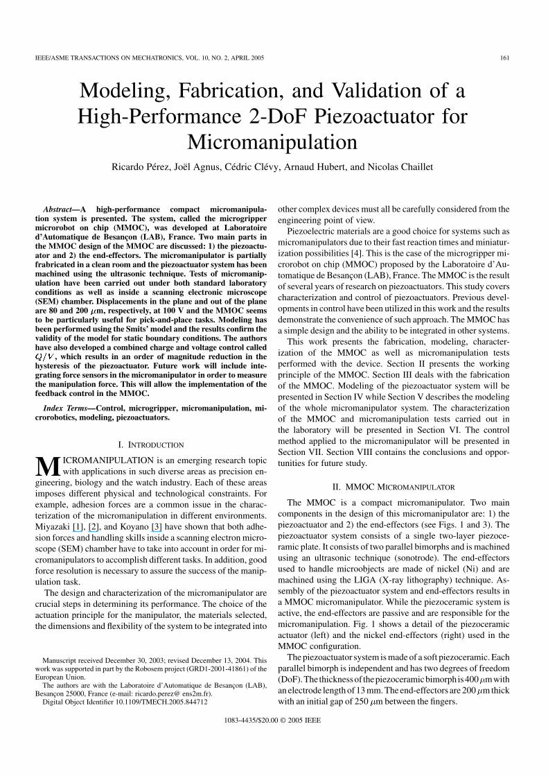
IEEE/ASME TRANSACTIONS ON MECHATRONICS, VOL. 10, NO. 2,APRIL 2005 161 Modeling, Fabrication, and Validation of a High-Performance 2-DoF Piezoactuator for Micromanipulation Ricardo Pérez, Joël Agnus, Cédric Clévy, Arnaud Hubert, and Nicolas Chaillet Abstract—A high-performance compact micromanipula- tion system is presented. The system, called the microgripper microrobot on chip (MMOC), was developed at Laboratoire d’Automatique de Besançon (LAB), France. Two main parts in the MMOC design of the MMOC are discussed: 1) the piezoactu- ator and 2) the end-effectors. The micromanipulator is partially frabricated in a clean room and the piezoactuator system has been machined using the ultrasonic technique. Tests of micromanip- ulation have been carried out under both standard laboratory conditions as well as inside a scanning electronic microscope (SEM) chamber. Displacements in the plane and out of the plane are 80 and 200 m, respectively, at 100 V and the MMOC seems to be particularly useful for pick-and-place tasks. Modeling has been performed using the Smits’ model and the results confirm the validity of the model for static boundary conditions. The authors have also developed a combined charge and voltage control called , which results in an order of magnitude reduction in the hysteresis of the piezoactuator. Future work will include inte- grating force sensors in the micromanipulator in order to measure the manipulation force. This will allow the implementation of the feedback control in the MMOC. Index Terms—Control, microgripper, micromanipulation, mi- crorobotics, modeling, piezoactuators. I. INTRODUCTION M ICROMANIPULATION is an emerging research topic with applications in such diverse areas as precision en- gineering, biology and the watch industry. Each of these areas imposes different physical and technological constraints. For example, adhesion forces are a common issue in the charac- terization of the micromanipulation in different environments. Miyazaki [1], [2], and Koyano [3] have shown that both adhe- sion forces and handling skills inside a scanning electron micro- scope (SEM) chamber have to take into account in order for mi- cromanipulators to accomplish different tasks. In addition, good force resolution is necessary to assure the success of the manip- ulation task. The design and characterization of the micromanipulator are crucial steps in determining its performance. The choice of the actuation principle for the manipulator, the materials selected, the dimensions and flexibility of the system to be integrated into Manuscript received December 30, 2003; revised December 13, 2004. This work was supported in part by the Robosem project (GRD1-2001-41861) of the European Union. The authors are with the Laboratoire d’Automatique de Besançon (LAB), Besançon 25000, France (e-mail: ricardo.perez@ ens2m.fr). Digital Object Identifier 10.1109/TMECH.2005.844712 other complex devices must all be carefully considered from the engineering point of view. Piezoelectric materials are a good choice for systems such as micromanipulators due to their fast reaction times and miniatur- ization possibilities [4]. This is the case of the microgripper mi- crorobot on chip (MMOC) proposed by the Laboratoire d’Au- tomatique de Besançon (LAB), France. The MMOC is the result of several years of research on piezoactuators. This study covers characterization and control of piezoactuators. Previous devel- opments in control have been utilized in this work and the results demonstrate the convenience of such approach. The MMOC has a simple design and the ability to be integrated in other systems. This work presents the fabrication, modeling, character- ization of the MMOC as well as micromanipulation tests performed with the device. Section II presents the working principle of the MMOC. Section III deals with the fabrication of the MMOC. Modeling of the piezoactuator system will be presented in Section IV while Section V describes the modeling of the whole micromanipulator system. The characterization of the MMOC and micromanipulation tests carried out in the laboratory will be presented in Section VI. The control method applied to the micromanipulator will be presented in Section VII. Section VIII contains the conclusions and oppor- tunities for future study. II. MMOC MICROMANIPULATOR The MMOC is a compact micromanipulator. Two main components in the design of this micromanipulator are: 1) the piezoactuator and 2) the end-effectors (see Figs. 1 and 3). The piezoactuator system consists of a single two-layer piezoce- ramic plate. It consists of two parallel bimorphs and is machined using an ultrasonic technique (sonotrode). The end-effectors used to handle microobjects are made of nickel (Ni) and are machined using the LIGA (X-ray lithography) technique. As- sembly of the piezoactuator system and end-effectors results in a MMOC micromanipulator. While the piezoceramic system is active, the end-effectors are passive and are responsible for the micromanipulation. Fig. 1 shows a detail of the piezoceramic actuator (left) and the nickel end-effectors (right) used in the MMOC configuration. The piezoactuator system is made of a soft piezoceramic. Each parallel bimorph is independent and has two degrees of freedom (DoF). The thickness of the piezoceramic bimorph is 400 m with an electrode length of 13 mm. The end-effectors are 200 m thick with an initial gap of 250 m between the fingers. 1083-4435/$20.00 © 2005 IEEE
Transcript of Modeling, fabrication, and validation of a high-performance 2DoF piezoactuator for micromanipulation
IEEE/ASME TRANSACTIONS ON MECHATRONICS, VOL. 10, NO. 2, APRIL 2005 161
Modeling, Fabrication, and Validation of aHigh-Performance 2-DoF Piezoactuator for
MicromanipulationRicardo Pérez, Joël Agnus, Cédric Clévy, Arnaud Hubert, and Nicolas Chaillet
Abstract—A high-performance compact micromanipula-tion system is presented. The system, called the microgrippermicrorobot on chip (MMOC), was developed at Laboratoired’Automatique de Besançon (LAB), France. Two main parts inthe MMOC design of the MMOC are discussed: 1) the piezoactu-ator and 2) the end-effectors. The micromanipulator is partiallyfrabricated in a clean room and the piezoactuator system has beenmachined using the ultrasonic technique. Tests of micromanip-ulation have been carried out under both standard laboratoryconditions as well as inside a scanning electronic microscope(SEM) chamber. Displacements in the plane and out of the planeare 80 and 200 m, respectively, at 100 V and the MMOC seemsto be particularly useful for pick-and-place tasks. Modeling hasbeen performed using the Smits’ model and the results confirm thevalidity of the model for static boundary conditions. The authorshave also developed a combined charge and voltage control called
, which results in an order of magnitude reduction in thehysteresis of the piezoactuator. Future work will include inte-grating force sensors in the micromanipulator in order to measurethe manipulation force. This will allow the implementation of thefeedback control in the MMOC.
Index Terms—Control, microgripper, micromanipulation, mi-crorobotics, modeling, piezoactuators.
I. INTRODUCTION
M ICROMANIPULATION is an emerging research topicwith applications in such diverse areas as precision en-
gineering, biology and the watch industry. Each of these areasimposes different physical and technological constraints. Forexample, adhesion forces are a common issue in the charac-terization of the micromanipulation in different environments.Miyazaki [1], [2], and Koyano [3] have shown that both adhe-sion forces and handling skills inside a scanning electron micro-scope (SEM) chamber have to take into account in order for mi-cromanipulators to accomplish different tasks. In addition, goodforce resolution is necessary to assure the success of the manip-ulation task.
The design and characterization of the micromanipulator arecrucial steps in determining its performance. The choice of theactuation principle for the manipulator, the materials selected,the dimensions and flexibility of the system to be integrated into
Manuscript received December 30, 2003; revised December 13, 2004. Thiswork was supported in part by the Robosem project (GRD1-2001-41861) of theEuropean Union.
The authors are with the Laboratoire d’Automatique de Besançon (LAB),Besançon 25000, France (e-mail: ricardo.perez@ ens2m.fr).
Digital Object Identifier 10.1109/TMECH.2005.844712
other complex devices must all be carefully considered from theengineering point of view.
Piezoelectric materials are a good choice for systems such asmicromanipulators due to their fast reaction times and miniatur-ization possibilities [4]. This is the case of the microgripper mi-crorobot on chip (MMOC) proposed by the Laboratoire d’Au-tomatique de Besançon (LAB), France. The MMOC is the resultof several years of research on piezoactuators. This study coverscharacterization and control of piezoactuators. Previous devel-opments in control have been utilized in this work and the resultsdemonstrate the convenience of such approach. The MMOC hasa simple design and the ability to be integrated in other systems.
This work presents the fabrication, modeling, character-ization of the MMOC as well as micromanipulation testsperformed with the device. Section II presents the workingprinciple of the MMOC. Section III deals with the fabricationof the MMOC. Modeling of the piezoactuator system will bepresented in Section IV while Section V describes the modelingof the whole micromanipulator system. The characterizationof the MMOC and micromanipulation tests carried out inthe laboratory will be presented in Section VI. The controlmethod applied to the micromanipulator will be presented inSection VII. Section VIII contains the conclusions and oppor-tunities for future study.
II. MMOC MICROMANIPULATOR
The MMOC is a compact micromanipulator. Two maincomponents in the design of this micromanipulator are: 1) thepiezoactuator and 2) the end-effectors (see Figs. 1 and 3). Thepiezoactuator system consists of a single two-layer piezoce-ramic plate. It consists of two parallel bimorphs and is machinedusing an ultrasonic technique (sonotrode). The end-effectorsused to handle microobjects are made of nickel (Ni) and aremachined using the LIGA (X-ray lithography) technique. As-sembly of the piezoactuator system and end-effectors results ina MMOC micromanipulator. While the piezoceramic system isactive, the end-effectors are passive and are responsible for themicromanipulation. Fig. 1 shows a detail of the piezoceramicactuator (left) and the nickel end-effectors (right) used in theMMOC configuration.
The piezoactuator system is made of a soft piezoceramic. Eachparallel bimorph is independent and has two degrees of freedom(DoF).The thicknessof thepiezoceramicbimorph is400 mwithan electrode length of 13 mm. The end-effectors are 200 m thickwith an initial gap of 250 m between the fingers.
1083-4435/$20.00 © 2005 IEEE

162 IEEE/ASME TRANSACTIONS ON MECHATRONICS, VOL. 10, NO. 2, APRIL 2005
Fig. 1. Piezoceramic actuator (left) and end-effectors (right) as maincomponents of the MMOC. The end-effectors are LIGA made and thepiezoceramic is machined with an ultrasonic cutting device.
Fig. 2. Two versions of microgripper MMOC (left) and LEMMOC (right).The example on the left is the first packaging version. The LEMO version onthe right is much more compact and has the same performance.
Fig. 3. General micromanipulator is composed by a piezoactuator system andend-effectors as those of the MMOC. In this case the actuation is made in the�-� plane.
The assembly of the piezoactuator system and end-effectorsgives a very compact and flexible configuration, which can beeasily integrated in complex systems such as micromanipulationplatforms. Fig. 2 shows two versions of the MMOC packagingfor micromanipulation tasks.
One of the main advantages of the micromanipulator config-uration shown in Fig. 3 is the compactness. A second advantagefor micromanipulation tasks is the possibility of actuation in the
– plane (as shown in the figure) or out from the – plane (axis) with this single structure.
III. FABRICATION
The fabrication process of a MMOC is presented in Fig. 4.The whole process is carried out in grey and clean rooms. Typi-cally, the assembly, machining, and packaging steps are not pre-formed in a clean room.
Soft piezoceramic plates (PIC 151) are used for the fabri-cation process. This piezoceramic is well adapted to the ap-plication requirements of the microgripper where quasi-staticworking conditions and large displacements are required. Thispiezoceramic has a coupling coefficient and a piezo-electric charge coefficient CN [8].
Fig. 4. Steps of the fabrication of the piezoactuator system of the MMOC usinga soft piezoceramic PIC151.
Fig. 5. Bimorph piezoactuator under different electromechanical constraintsdefined in the Smits’ model.
After the bonding of two piezoceramic layers using a con-ductive epoxy glue (step 1), a resin is applied on the electrodesurface (step 2) before carrying out the photolithography(steps 3–5). The electrode pattern is defined for the design ofthe piezoactuator in the masks (step 3). After developmentby UV exposure (step 5), the resulting plate is ready to bemachined. Machining of the piezoactuator system for themicromanipulator is performed using an ultrasonic machiningtechnique [9], [10], with the advantage of having low impacton the material properties of the piezoceramic substrate.
Fabrication tolerances play an important role in the perfor-mance of the micromanipulator. Generally, two main sourcescan be differentiated. The first is the alignment of electrodesof two bimorphs that can be highly affected by the tolerancesduring the photolithography. This misalignment can decreasethe performance of the microgripper through the introductionof undesirable parasitic displacements. The second source oferror is the machining of prototypes from the piezoceramic plateusing the ultrasonic technique.
IV. MODELING OF A BIMORPH PIEZOACTUATOR
The model of the piezoactuator system presented in this sec-tion aims to determine the fundamental parameters such as dis-placement or deflection angle depending upon the boundaryconditions applied to the bimorph piezoactuator. The Smits’model [11] is used to accomplish this task. It consists of a setof equations that are used to calculate parameter magnitudes re-lated to a bimorph piezoactuator under electromechanical con-straints as shown in Fig. 5.
The output magnitudes in the Smits’ model are angle , flec-tion , removed volume , and charge under mechanical orelectrical constraints such as bending moment , force , pres-sure , and voltage . Equation (1) shows the matrix form of the

PÉREZ et al.: MODELING, FABRICATION, AND VALIDATION OF A HIGH-PERFORMANCE 2-DoF PIEZOACTUATOR 163
TABLE ICOEFFICIENTS FOR THE �-MODE
general Smits’ model. Index means the - or -mode, respec-tively
(1)
Coefficients are calculated according to Smits et al. [11]from the piezoelectric equations, the bending moment balanceequation and the internal energy balance
(2)
(3)
(4)
(5)
is the strain, the compliance coefficient, the me-chanical stress, the charge piezoelectric coefficient, theelectric field, the charge density, and the electric permit-tivity. Coefficients for the mode obtained by Smits et al. arepresented in Table I.
The basic working principle of a single finger in the piezoac-tuator system is the principle of a parallel bimorph. A uniquefeature of this bimorph is that it has two DoF. Fig. 6 shows thegeometrical configuration of this piezoactuator. The output dis-placements and at the output of the beam are also repre-sented.
Fig. 7 shows the working principle of the geometrical con-figuration of Fig. 6. Applying a voltage results in the outputdisplacement as pictured in Fig. 7(a).
Displacement results from the application of a voltageand in a cross configuration on the electrodes. Cases a andb will be called hereafter -mode and -mode, respectively. Athird working configuration is possible if voltages and areapplied simultaneously on the electrodes. The output displace-ment is a coupled displacement between the - and -modeas shown in Fig. 7(c).
Fig. 6. Geometrical configuration of the duo-bimorph used for themicromanipulator. Displacemen in the � and � axis are possible thanksto the design.
Fig. 7. Working principle of the duo-bimorph with the electric configurationresulting in displacements � , � and a combination of both.
TABLE IICOEFFICIENTS FOR THE �-MODE
In a previous work [12], the authors have presented an ex-tension of the Smits’ model to obtain coefficients for the
-mode. In that work, however, de Lit et al. [12] did not calcu-late coefficients for and concerningthe charge as the result of the , , , and . These coeffi-cients have now been calculated following the Smits’ approachand are outlined in Table II.
Actuation in - and -mode can be written in a compact formshown in (6). No coupling between the - and -mode is con-sidered in this case
(6)

164 IEEE/ASME TRANSACTIONS ON MECHATRONICS, VOL. 10, NO. 2, APRIL 2005
An important working parameter of piezoactuators is theblocking force needed to cancel the displacement generatedwhen a voltage is applied as shown in Fig. 5
(7)
(8)
The ratio between blocking forces in - and –mode dependsonly upon the geometry. For bimorph configurations, such asthat used for the MMOC, the ratio between width and thicknessis
(9)
Another important parameter from the modeling point ofview is the evaluation of the mechanical coupling and theefficiency of the bimorph system. According to Wang et al.[13], the coupling coefficient of the piezoelectric bimorph inconfiguration is calculated according to
(10)
The coupling coefficient of the piezoactuator is definedas the ratio between the mechanical energy output andthe electrical energy input as: . Theelectrical and mechanical energy are defined according toWang [13] as and
.The coupling coefficient is calculated according to the
standard equation and it is a function of the intrinsic parametersof the piezoceramic [14]
(11)
The coupling coefficient related to the -mode is calculatedin the same way as that for the -mode
(12)
In comparing and , it is found that is four timeslarger than . This result is expected if we take into accountthat the stiffness is higher for the -mode and consequently themechanical energy produced for a given electrical energy inputis smaller. This result must be taken into account for workingand design purposes.
V. STATIC MODEL OF THE MICROMANIPULATOR
A simplified model of one finger of the micromanipulator isconsidered in Fig. 8(a). This model takes into account only onefinger of the micromanipulator system shown in Fig. 3.
The piezoelectric actuator and the end-effector are representedas piezoelectric and metallic beams, respectively. They are de-fined by length for the piezoelectric beam and length
Fig. 8. Simplified model of a micromanipulator used in the analytical andFE models. The active and nonactive parts represent the piezoceramic and theend-effector, respectively.
Fig. 9. Micromanipulation system with active part, piezoactuator, and passivepart, end-effector. A force � is applied on the tip of the end-effector generatinga bending moment � .
for the end-effector. Both beams have their own material proper-ties including the compliance and, in the case of the piezoce-ramic beam, the piezoelectric charge coefficient .
When a voltage is applied to the bimorph, the piezoceramicbeam bends and the end-effector rotates without deformationas shown in Fig. 8(b). This is the case of one gripper of themicromanipulator shown in Fig. 8(c). The whole system can bescaled according to the magnitude of force and the diameter
of the object to be handled.Equations used to calculate deflection correspond to those
given by de Lit [12] for the -mode. When a voltage is ap-plied, bending of the whole structure takes place. If a forceis applied on the end-effector, a bending moment on the bi-morph beam will appear as shown in Fig. 9.
The present model has been applied to the configuration of a2-DoF microactuator. Nevertheless, it can also be applied to thestudy of micropositioning and scanning tasks, for example.
The flection function and output angle for the wholesystem (piezoactuator and end-effector) when no force on theend-effector tip is applied is calculated from the previous modelas follows in (13). The superscript indicate parametersconcerning the piezoelectric beam
(13)

PÉREZ et al.: MODELING, FABRICATION, AND VALIDATION OF A HIGH-PERFORMANCE 2-DoF PIEZOACTUATOR 165
where and can be calculated from the followingequations:
(14)
(15)
When a force is applied on the end-effector, the new flec-tion function becomes (16), shown at the bottom of the page.
Superscript indicates flexion of the PZT beam underforce applied on the end-effector. In this case, flexion ofthe piezoceramic beam is due to the voltage and the bendingmoment as shown in the following equations:
(17)
The output angle after applying force is calculated thenfrom the general model as shown in the following equation:
(18)
The bending moment applied at the end of the piezoelec-tric beam is calculated from the classical mechanics equation
(19)
Equations (12)–(18) permit the assessment of the influence ofinteraction forces on the micromanipulation system. Force issupposed to be opposite to the bending due to the voltage. Thismeans that expected output flection at the end of the end-effectoris less than in the free case [Fig. 7(b)]
(20)
Fig. 10 shows the effect of the reaction forces on the deflec-tion of finger according to Fig. 9. The blocking force canbe considered as a reference limit. Reaction forces when han-dling are in general much smaller than and depend on ob-ject to be handled. A rough approach of the order of interactionforces in the micromanipulator is where constanthas to be determined for each particular case of manipulation.
A force of 50 mN for instance reduces the free voltagebending of 15% according to the results of the analyticalmodel developed in this section. For the present case, theblocking force can be calculated from (21). The condition tocalculate the blocking force comes from the equation
(21)
Fig. 10. Variation of the deflexion � with the reaction force � . The limit isgiven by the � axis (� � �), which represents the blocking force of the wholesystem, bimorph and end-effector.
The last equation can be simplified under the approximationthat and are sufficiently small and consequentlythe product can be neglected. The remainingequation for the blocking force condition is
(22)
Substituting from (17) and (18)
(23)
The last equation is similar to the precedent equations for theblocking forces in - and -modes. The main difference is theratio between the piezoceramic and end-effector lengthsand .
VI. CHARACTERIZATION OF THE MICROMANIPULATOR
Characterization of a MMOC micromanipulator has beendone with samples shown in Fig. 2 in two different environ-ments: the laboratory and SEM chamber. Results obtained inboth cases are quite close and no influence of the environmenton the performance of the MMOC has been observed. Outputdisplacements of the micromanipulator are 200 m outside the
- plane (called axis) and 80 m in the - plane (calledaxis) at 100 V. Fig. 11 shows the hysteresis loop of the tip of theend-effector and the theoretical value expected. Measurementsare quite close to the theoretical values obtained with theproposed model in Sections IV and V. Hysteresis measured in
(16)

166 IEEE/ASME TRANSACTIONS ON MECHATRONICS, VOL. 10, NO. 2, APRIL 2005
Fig. 11. Variation of the deflection � versus the applied voltage � fora piezoactuator beam. Results from the model (dots) and hysteresis loopsmeasured in the laboratory are plotted.
Fig. 12. Variation of the deflection � with the frequency. The first resonancefrequency is situated at 400 Hz.
the laboratory for this case is 24.6%. Similar values have beenmeasured in the SEM chamber.
Frequency characterization has also been performed in thelaboratory and the results are shown in Fig. 12. The first bendingmode outside the - plane corresponds to 400 Hz. The band-width estimated from the results is 100 Hz for the MMOC ver-sion shown in Fig. 2.
VII. CONTROL
Preliminary results concerning a charge control for the dis-placements of piezoactuators in open loop have been proposedby the authors in a previous work [15]. We propose to describein this section a control method based on the combination ofconstant charge control and constant voltage control. An impor-tant reduction of the hysteresis, up to one order of magnitudeless than the nominal value of the hysteresis, is obtained by thismethod.
Piezoactuators are generally controlled using either an openloop with voltage control input or a closed loop with a position
Fig. 13. Hysteresis loop of a piezoceramic for a displacement voltagerepresentation.
Fig. 14. Control principles of piezoelectric actuators. � and � are,respectively, the voltage and the electrical charge applied on the piezoactuator,� is the strain of the material.
set point and an applied voltage on the actuator. The first caseconsists of a simple control in which a voltage is applied to theterminals of the piezoactuator. The main disadvantage of thismethod is the nonlinearity between the deformation (position)and voltage. Typical values of hysteresis for a soft piezoceramiccan reach 20%. Fig. 13 shows the hysteresis loop of a piezoce-ramic for a displacement ( )–voltage representation.
Due to the lack of precision in the displacement , three dif-ferent solutions can be used. The first consists of implementinga position servomechanism. This method is very efficient, butit is also very expensive because of the position sensor and theappropriate regulation system required. Another solution to thisproblem is the implementation of linear control based on thebehavior of inverse models such as those of Preisach [16] andMaxwell [17]. The disadvantage of this approach is the lackof robustness of the linearization when the model is appliedto different kinds of piezoactuators. A third solution consistsin using a compliance feedback charge driver [18], [19], whichoffers less hysteresis than voltage control and compensates forcharge losses. This method gives low-frequency bandwidths inthe megahertz range but the proposed control method can keepthe position in static conditions that could be needed within po-sitioning applications.
A. Control With Constant Charge
Generally, piezoactuators are controlled with the appliedvoltage due to the ease of implementation of such a system.Nevertheless, the electromechanical transfer between the ap-plied voltage and the strain is not linear. Hence, the strain isnot the proportional as the voltage increases and decreases[see Fig. 14(a)]. Another control option consists of using acharge control [see Fig. 14(b)]. As a result, a constant quantityof free electrical charges is applied on the electrodes of thepiezoactuator. This control method results in a more linearbehavior between the applied charge and the strain.
Equations (24) and (25) can be used to explain the differencebetween the voltage and charge control methods. Under no ex-ternal stress ( ), (2) (see Section IV) indicates that the

PÉREZ et al.: MODELING, FABRICATION, AND VALIDATION OF A HIGH-PERFORMANCE 2-DoF PIEZOACTUATOR 167
Fig. 15. Phenomenology of the charge control on the quantity of free chargeson the electrodes of a piezoceramic with polarization � and thickness �.
Fig. 16. Phenomenology of charge control of a piezoceramic with polarization� and thickness �.
strain is proportional to the electric field . For the elon-gation of a planar piezoceramic structure, can be written bysubstitution of from (24) and (25) as follows:
(24)
The Gauss law allows determination of the free charge quan-tity on the electrodes of the piezoceramic as follows:
(25)
where is the surface of the electrode. Substituting from(25) into (24), we obtain the linear equation of the strain linkedto the stress and the free charges as
(26)
Fig. 15 shows the result when a constant voltage is appliedon the electrodes of a piezoactuator. If a polled ceramic ( )with a thickness is considered and a voltage is applied at
, a quantity of free charges appears on the electrodesof the piezoactuator. At , after the complete strain of thematerial is reached, the polarization becomes and thethickness increases to .
To keep the voltage constant, some additional free chargesare added by the voltage supply (schematically represented byone more charge on the extended configuration of Fig. 16). Inthis voltage control, the quantity of free charges is not main-tained. Consequently, the relation between voltage and strainis not linear for the piezoactuator. In the case of a free chargecontrol (see Fig. 16), the charge is maintained constant and thestrain is proportional to this quantity as pointed out in (26).
The principle of the charge control [see Fig. 17(a)] has beenproposed by Comstock [20] and used for a stack by Main [21].In this work, it is demonstrated that the charge in a piezoac-tuator obeys the equation: . Newcomb [22]proposes a solution based on the constant current integrationwithin a given time to obtain a charge amount: ,
Fig. 17. Different control implementations to achieve a constant quantity ofcharge on the electrodes of the actuator.
Fig. 18. Voltage control: strain � stable in time, but the transfer between �and � is nonlinear.
Fig. 19. Charge control: linear transfer between � and�, but discharge of theactuator.
where [Fig. 17(b)]. Newton [23] improves thisprinciple by measuring the amount of charge through an inte-grator [Fig. 17(c)]. Janocha [24], [25], presents a technical so-lution equivalent to the previous one but the current integrationis measured by means of a software structure.
B. Control
Two major difficulties have to be overcome when workingwith methods in constant voltage and constant charge.
1) Voltage control of piezoactuators presents a hysteresis be-tween the applied voltage and generated deformation (seeFig. 18). The main difficulty is to make this control linear.
2) Charge control of piezoactuators can result in positiondrift as the charge dissipates (see Fig. 19). The time con-stant of the discharge depends on the piezoactuator andgoes from some hundreds of milliseconds to tens of sec-onds. The problem to be solved is how to avoid the lossof charges.
This section presents the principle of the control devel-oped by the authors. This control allows a static linear behaviorin open loop between the deformation of a piezoactuator and itscontrol signal. A hybrid control in charge and voltage is used forthis purpose. The resulting control takes advantage of the bestfeatures of each of these two control methods.

168 IEEE/ASME TRANSACTIONS ON MECHATRONICS, VOL. 10, NO. 2, APRIL 2005
Fig. 20. Flow chart of the ��� control using a combination of voltage andcharge control method.
Fig. 20 shows the working principle of the control in aflow chart. Four steps are considered in this approach.
1) Application of a quantity of charges to the electrodes ofthe piezoactuator for a given displacement according to aposition control.
2) Measurement of the voltage at the electrodes of thepiezoactuator for the quantity of charges applied.
3) Application of a voltage to keep constant the electriccharge at the electrodes of the piezoactuator.
4) If the set point is changed, the circuit repeats the three firststeps by applying a new quantity of charge. Otherwise, thecircuit maintains the charge until a new set value is given.
The implementation of this solution consists of switching inreal time from a first configuration to a second one. The firstconfiguration consists of applying a quantity of controlled elec-tric charges to the electrodes of the piezoactuator. The secondstep consists of applying a continuous voltage corresponding tothe charge previously applied. The applied voltage maintains thecharge at the desired value.
Fig. 21(a)–(c) show the solution developed in this work. Theswitching between the charge and voltage controls is made usinghigh-speed CMOS analogical switches to controlled bythe logic signal . Switch , controlled by , is positioned over’Reset’ with and to at ’voltage mode’ with to de-fine the initial conditions of the device ( V, C).
The functional block makes measurements of the outputvoltage of the amplifier . The latter is mainly composed of again to reach that allows the calculation of , i.e., thecontinuous voltage to apply in order to keep the charge constantthrough a voltage amplifier (AOP, , ), as
(27)
Fig. 22 compares the free deflection measured using voltagecontrol and control for a bimorph piezoactuator in
-mode. Voltage control of the piezoactuator gives a hysteresisof 21% for the total amplitude of the deflection. For thecontrol, the residual hysteresis is reduced to 3.4%. In thisexample, measurement of is the measure of the quantity ofcharges applied ton the actuator, and the switching fromcharge control to voltage control is made in a time of 20 msafter the application of the charge.
The control is particularly suitable within microposi-tioning applications when we need to keep a constant positionbut is not well adapted within high dynamic applications likeactive noise control because of the delay to measure the voltagecorresponding to the applied charges.
VIII. MICROMANIPULATION TESTS
Micromanipulation is the goal of the MMOC developedat LAB. Training and testing have been carried out with theMMOC in different environments. It has shown the possibilitiesand limitations of the micromanipulator system.
The MMOC prototype includes duo-bimorphs whose dimen-sions are 13 mm long, 1 mm wide and 0.4 mm thick. These areintegrated into a LEMO connector 43 mm long and 12 mm indiameter from which emerge the useful parts that are in con-tact with the manipulated objects., i.e., the end-effectors. Theend-effectors are 12 mm long and 0.2 mm thick.
The performance of the MMOC is characterized by the fol-lowing.
1) The measured strokes of open/close motions and up/downmotions are 320 and 400 m, respectively, for V.
2) The estimated blocking forces on each end-effector tip are55 mN in gripping (open/close, direction) and 10 mN ininsertion (up/down, direction) for 100 V. These estima-tions were obtained using a finite element modeling.
3) The measured first resonance frequency is 1070 Hz forgripping motion and 450 Hz for up and down motion.
One of the environments considered for the training andtesting step has been a SEM chamber. One of the advantagesof this experience is the possibility of observing with highprecision the micromanipulation process. Fig. 23 shows someof these micromanipulation tests developed in a SEM chamberwith a MMOC sample.
Manipulation grains in the pictures correspond to a Ni-Coalloy powder. The size of grains ranges from 150 to 200 m.These dimensions suit the range of displacements of the micro-manipulator. Pick-and-place tasks have been carried out in theSEM chamber. The main difficulty to this operation is the coarseapproach in when handling the powder and is the subject offurther study.
A crucial point to be regarded in the near future in thesepick-and-place operations is the role and the quantification ofthe adhesion forces. For this, a force sensor is necessary. Forcesensors are widely studied at present in microrobotics and au-tomation fields [5]–[7], however, currently, no force sensor hasbeen implemented in the micromanipulation system presentedin this section. Much effort is being made at present to permitthe integration of a force sensor in the MMOC configuration.
PÉREZ et al.: MODELING, FABRICATION, AND VALIDATION OF A HIGH-PERFORMANCE 2-DoF PIEZOACTUATOR 169
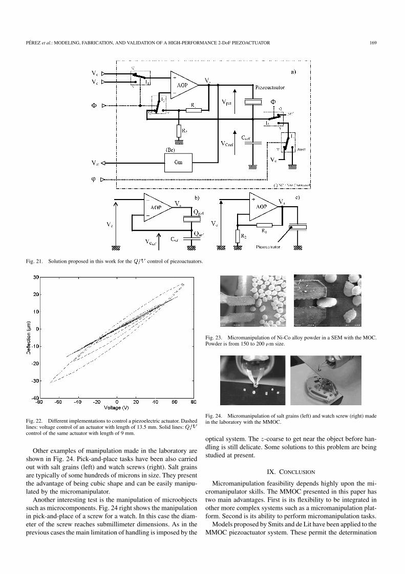
Fig. 21. Solution proposed in this work for the ��� control of piezoactuators.
Fig. 22. Different implementations to control a piezoelectric actuator. Dashedlines: voltage control of an actuator with length of 13.5 mm. Solid lines: ���control of the same actuator with length of 9 mm.
Other examples of manipulation made in the laboratory areshown in Fig. 24. Pick-and-place tasks have been also carriedout with salt grains (left) and watch screws (right). Salt grainsare typically of some hundreds of microns in size. They presentthe advantage of being cubic shape and can be easily manipu-lated by the micromanipulator.
Another interesting test is the manipulation of microobjectssuch as microcomponents. Fig. 24 right shows the manipulationin pick-and-place of a screw for a watch. In this case the diam-eter of the screw reaches submillimeter dimensions. As in theprevious cases the main limitation of handling is imposed by the
Fig. 23. Micromanipulation of Ni-Co alloy powder in a SEM with the MOC.Powder is from 150 to 200 �m size.
Fig. 24. Micromanipulation of salt grains (left) and watch screw (right) madein the laboratory with the MMOC.
optical system. The -coarse to get near the object before han-dling is still delicate. Some solutions to this problem are beingstudied at present.
IX. CONCLUSION
Micromanipulation feasibility depends highly upon the mi-cromanipulator skills. The MMOC presented in this paper hastwo main advantages. First is its flexibility to be integrated inother more complex systems such as a micromanipulation plat-form. Second is its ability to perform micromanipulation tasks.
Models proposed by Smits and de Lit have been applied to theMMOC piezoactuator system. These permit the determination

170 IEEE/ASME TRANSACTIONS ON MECHATRONICS, VOL. 10, NO. 2, APRIL 2005
of different parameters related to the performance of the systemincluding the output displacement. According to the applica-tion domain and boundary conditions, scaling of the piezoac-tuator system such as the duo-bimorph can be made using thesemodels.
The proposed model can be applied to characterize the perfor-mance of a duo-bimorph with end-effector. It can also be appliedto other systems such as micro positioning or scanning systems.In the case of the micromanipulation, the end-effector is respon-sible of handling objects. The influence of handling forces isassessed with the model proposed by the authors. According tothe results, forces of some tens of milli-Newtons on the end-ef-fectors produce a reduction of 10% in the displacement ofthe micromanipulator. Characterization of the MMOC has beenmade under static and frequency dependent boundary condi-tions. Displacements in the - ( - plane) and -mode (out ofthe - plane) are 80 and 200 m at 100 V, respectively. Hys-teresis can reach 25% for an open-loop configuration. The firstresonance frequency corresponds to a displacement out fromthe - plane at 400 Hz.
A control developed by the authors has been imple-mented. The principle of the control takes advantage ofthe charge and voltage controls. It makes the reduction of thehysteresis in a factor of 10 possible. In addition, charges arekept on the electrodes of the piezoactuator. This method doesnot need a control model and can be consequently applied to anypiezoactuator. The only limitation of this method is imposed bythe electronics. Parameters necessary for the implementation ofthis control are the value of the capacity and the response timeto a step function of the piezoactuator. These characteristics areeasily obtained from the data sheet of the manufacturer and con-sequently do not represent a limitation on the implementationthis control. Finally, the control method presented in this workcan be applied to any piezoactuator.
Micromanipulation training and tests have been carried out ina SEM chamber and in the laboratory. Results confirm both thepotential applications of the MMOC as well as the difficultiesin handling objects, primarily due to the limitation of the optics.
A further step in the design of the MOC micromanipulator isthe integration of a force sensor to permit the feedback controlduring the manipulation.
ACKNOWLEDGMENT
The authors would like to thank the team of the LCEP lab-oratory, Besançon, France, responsible of the machining of thepiezoceramic actuators.
REFERENCES
[1] H. Miyazaki and T. Sato, “Mechanical assembly of three-dimensionalmicrostructures from fine particles,” Adv. Robot., vol. 11, no. 2, pp.169–185, 1997.
[2] H. T. Miyazaki, Y. Tomizawa, K. Koyano, T. Sato, and N. Shinya, “Ad-hesion force measurement system for microobjects in a scanning elec-tron microscope,” Rev. Scientific Instrum., vol. 71, no. 8, pp. 3123–3131,2000.
[3] K. Koyano and T. Sato, “Micro object handling system with concen-trated visual fields and new handling skills,” Proc. SPIE, vol. 2906, pp.130–140, 2003.
[4] S. T. Smits and D. G. Chetwynd, “Foundation mechanism design,” inDevelopments in Nanotechnology, K. K. Bowen, Ed. Warwick, U.K.:Gordon and Breach Science, 1999, vol. 2.
[5] K. Uchino, Piezoelectric Actuators and Ultrasonic Motors, H. L. Tuller,Ed. New York: Academic, 1997.
[6] T. Tanikawa, M. Kawai, N. Koyachi, T. Arai, T. Ide, S. Kaneko, R. Ohta,and T. Hirose, “Force control system for autonomous micro manipula-tion,” in Proc. IEEE. Int. Conf. Robotics and Automation, Seoul, Korea,2001, pp. 610–615.
[7] Y. Shen, N. Xi, W. J. Li, and J. Tan, “A high sensitivity force sensorfor microassembly: Design and experiments,” in Proc. IEEE/ASME. Int.Conf. Advanced Intelligent Mechatronics, vol. 2, 2003, pp. 703–708.
[8] Piezoelectric Ceramics and Components, PI ceramic, 1998.[9] V. Soundararajan and V. Radhakrishnan, “An experimental investigation
on the basic mechanisms involved in ultrasonic machining,” Int. Mach.Tool Des. Res., vol. 26, no. 3, pp. 307–321, 1986.
[10] S. Ballandras, P. Maître, P. Guine, N. Bourriot, W. Steichen, B. Piranda,and J. F. Gelly, “New results on miniaturised annular arrays built usingultrasound micromachining,” in Proc. IEEE Ultrasonics Symp., 1999,pp. 1159–1162.
[11] J. G. Smits, S. I. Dalke, and T. K. Cooney, “The constituent equations ofpiezoelectric bimorphs,” Sens. Actuators A, vol. 28, pp. 41–61, 1991.
[12] P. De Lit, J. Agnus, and N. Chaillet, “The constitutive equations of apiezoelectric duo-bimorph,” in Proc. 5th IEEE. Int. Symp. Assembly andTask Planning, Besançon, France, Jul. 2003, pp. 1–6.
[13] Q.-M. Wang, X.-H. Du, B. Xu, and L. E. Cross, “Electromechanicalcoupling and output efficiency of piezoelectric bending actuators,” IEEETrans. Ultras., Ferroelectr., Freq. Contr., vol. 46, no. 3, pp. 638–646,Mar. 1999.
[14] IEEE Standard on Piezoelectricity, ANSI/IEEE Std. 176, 1998.[15] R. Pérez, J. Agnus, J.-M. Breguet, N. Chaillet, H. Bleuler, and R. Clavel,
“Characterization and control of a 1 DoF monolithic piezoactuator(MPA),” Proc. SPIE , pp. 151–162, 2001.
[16] P. Ge and M. Jouaneh, “Tracking control of a piezoceramic actuator,”IEEE Trans. Contr., Syst. Technol., vol. 4, no. 3, pp. 209–216, Mar. 1996.
[17] M. Goldfarb and N. Celanovic, “Modeling piezoelectric stack actuatorsfor control of micromanipulation,” IEEE Contr. Syst. Mag., vol. 17, no.3, pp. 69–79, Jun. 1997.
[18] A. J. Fleming and S. O. R. Moheimani, “Improve current and chargeamplifiers for driving piezoelectric loads, and issues in signal processingdesign for synthesis of shunt damping circuits,” J. Intell. Mater. Syst.Structures, vol. 15, no. 2, pp. 77–92, 2004.
[19] S. O. R. Moheimani, J. Fleming, and S. Behrens, “Dynamics, stability,and control of multivariable piezoelectric schunts,” IEEE/ASME Trans.Mechatron., vol. 9, no. 3, pp. 87–99, Mar. 2004.
[20] R. Comstock, “Charge control of piezoelectric actuators to reduce hys-teresis effects,” U.S. Patent 4 263 527, 1981.
[21] J. Main, E. Garcia, and D. Newton, “Precision position control of piezo-electric actuators using charge feedback,” J.Guidance, Contr. Dynamics,vol. 18, no. 5, pp. 1068–1073, 1995.
[22] C. Newcomb and I. Flinn, “Improving the linearity of piezoelectric ce-ramic actuators,” Electron. Lett., vol. 18, no. 11, pp. 442–443, 1982.
[23] D. Newton, J. Main, and E. Garcia, “Piezoelectric actuation systems:Optimization of driving electronics,” in Proc. SPIE, vol. 2717, 1996, pp.259–266.
[24] H. Janocha, D. Jendritza, and P. Scheer, “Smart actuators with piezoelec-tric materials,” in Proc. 3rd ICIM/ECSSM Conf., 1996, pp. 603–609.
[25] H. Janocha and K. Kuhnen, “Real-time compensation of hysteresis andcreep in piezoelectric actuators,” J. Sens. Actuators, vol. 79, pp. 83–89,2000.
Ricardo Pérez received the master of physics-astro-physics degree from the University of La Laguna, LaLaguna, Spain, in 1993, the postmaster degree in en-ergy systems in 1998, and the Ph.D. degree in mi-crotechnologies in 2002, both from the Ecole Poly-technique Fédérale de Lausanne (EPFL), Lausanne,Switzerland.
He is currently Postdoctoral Researcher at theLaboratoire d’Automatique de Besançon, Besançon,France. His research interests are microactuators,microtecnologies, and modeling of microsystems.

PÉREZ et al.: MODELING, FABRICATION, AND VALIDATION OF A HIGH-PERFORMANCE 2-DoF PIEZOACTUATOR 171
Joël Agnus received the M.S. degree in electrical en-gineering in 1994 and the Ph.D degree in automaticcontrol and computer sciences from the University ofBesançon, Besançon, France, in 2003.
He has been an engineer at the Laboratoired’Automatique de Besançon, Besançon, France,since 1996. His current research interests are inthe microrobotics field and, more particular, in themicromanipulation domain and microgrippers.
Cédric Clévy graduated from the Ecole NormaleSupérieure de Cachan, Cachan, France, in 2001and received the master degree of mechanical en-gineering, automatics and automation in 2002. Heis currently working toward the Ph.D. degree in theLaboratory of Automation of Besançon, Besançon,France.
His research interests are microrobotic, microfac-tories, and micromanipulation cells using grippersand tools changer
Arnaud Hubert received the engineer diploma inmechanical engineering in 1996, the DEA (M.Sc)degree in system control in 1997, and the Ph.D de-gree in 2000, all from the University of Technologyin Compiegne, Compiegne, France. His Ph.D.research was about noise and vibrations control inelectrical drives.
Since 2002, he has been an Assistant Professor atthe University of Besançon, Besançon, France, and aResearcher at the Automatic Laboratory in Besancon(LAB), Besançon. His current research interests are
the design of microrobotic systems and actuators as well as the control of smartmaterials.
Nicolas Chaillet received the B.S.E. degree inelectrical engineering from the Ecole NationaleSupérieure de Physique, Strassbourg, France, in1990, and the Ph.D. degree in robotics and automa-tion from the University Louis Pasteur, Strasbourg,France, in 1993.
In 1995, he became an Associate Professor atthe University of France-Comté, Besançon, France,working at the Laboratoire d’Automatique de Be-sançon (LAB). Since 2001, he has been a Professorat the University of Franche Comté and the Head of
the LAB Micromanipulation and Microactuators Research Group. His researchinterests are in microrobotics and, more generally, in micromechatronics fields,especially in micromanipulation, mocrogrippers, smart materials, modeling,and control of microactuators.