The Terabit/s Super-Fragment Builder and Trigger Throttling System for the Compact Muon Solenoid...
7
Available on CMS information server CMS CR-2007/020 CMS Conference Report May 11, 2007 The Terabit/s Super-Fragment Builder and Trigger Throttling System for the Compact Muon Solenoid Experiment at CERN G. Bauer 9 , V. Boyer 5 , J. Branson 6 , A. Brett 5 , E. Cano 5 , A. Carboni 5 , M. Ciganek 5 , S. Cittolin 5 , S. Erhan 5,7 , D. Gigi 5 , F. Glege 5 , R. Gomez-Reino 5 , M. Gulmini 2,5 , E. Gutierrez Mlot 5 , J. Gutleber 5 , C. Jacobs 5 , J. C. Kim 4 , M. Klute 9 , E. Lipeles 6 , J. A. Lopez Perez 5 , G. Maron 2 , F. Meijers 5 , E. Meschi 5 , R. Moser 1,5 , S. Murray 8 , A. Oh 5 , L. Orsini 5 , C. Paus 9 , A. Petrucci 2 , M. Pieri 6 , L. Pollet 5 , A. Racz 5 , H. Sakulin 5 , M. Sani 6 , P. Schieferdecker 5 , C. Schwick 5 , K. Sumorok 9 , I. Suzuki 8 , D. Tsirigkas 5 and J. Varela 3,5 1 Vienna University of Technology, Vienna, Austria 2 INFN - Laboratori Nazionali di Legnaro, Legnaro, Italy 3 LIP, Lisbon, Portugal 4 Kyungpook National University, Daegu, Kyungpook, South Korea 5 CERN, Geneva, Switzerland 6 University of California San Diego, La Jolla, California, USA 7 University of California, Los Angeles, California, USA 8 FNAL, Batavia, Illinois, USA 9 Massachusetts Institute of Technology, Cambridge, Massachusetts, USA Presented by Hannes Sakulin ([email protected]) Abstract The Data Acquisition System of the Compact Muon Solenoid experiment at the Large Hadron Collider reads out event fragments of an average size of 2 kilobytes from around 650 detector front-ends at a rate of up to 100 kHz. The first stage of event-building is performed by the Super-Fragment Builder employing custom-built electronics and a Myrinet optical network. It reduces the number of fragments by one order of magnitude, thereby greatly decreasing the requirements for the subsequent event-assembly stage. By providing fast feedback from any of the front-ends to the trigger, the Trigger Throttling System prevents buffer overflows in the front-end electronics due to variations in the size and rate of events or due to back-pressure from the down-stream event-building and processing. This paper reports on new performance measurements and on the recent successful integration of a scaled-down setup of the described system with the trigger and with front-ends of all major sub-detectors. The on-going commissioning of the full-scale system is discussed. Presented at IEEE NPSS Real Time Conference 2007, Fermilab, Batavia IL, April 29 – May 4, 2007 Submitted to IEEE Transactions of Nuclear Science FERMILAB-CONF-07-363-E
-
Upload
polysaccharides -
Category
Documents
-
view
0 -
download
0
Transcript of The Terabit/s Super-Fragment Builder and Trigger Throttling System for the Compact Muon Solenoid...
Available on CMS information server CMS CR-2007/020
CMS Conference Report
May 11, 2007
The Terabit/s Super-Fragment Builder and Trigger Throttling System for the Compact Muon Solenoid
Experiment at CERN G. Bauer9, V. Boyer5, J. Branson6, A. Brett5, E. Cano5, A. Carboni5, M. Ciganek5, S. Cittolin5, S. Erhan5,7, D. Gigi5, F. Glege5, R. Gomez-Reino5, M. Gulmini2,5, E. Gutierrez Mlot5, J. Gutleber5, C. Jacobs5, J. C. Kim4, M. Klute9, E. Lipeles6, J. A. Lopez Perez5, G. Maron2, F. Meijers5, E. Meschi5, R. Moser1,5, S. Murray8, A. Oh5, L. Orsini5, C. Paus9, A. Petrucci2, M. Pieri6, L. Pollet5, A. Racz5, H. Sakulin5, M. Sani6, P. Schieferdecker5, C. Schwick5, K.
Sumorok9, I. Suzuki8, D. Tsirigkas5 and J. Varela3,5
1Vienna University of Technology, Vienna, Austria 2INFN - Laboratori Nazionali di Legnaro, Legnaro, Italy
3LIP, Lisbon, Portugal 4Kyungpook National University, Daegu, Kyungpook, South Korea
5CERN, Geneva, Switzerland 6University of California San Diego, La Jolla, California, USA
7University of California, Los Angeles, California, USA 8FNAL, Batavia, Illinois, USA
9Massachusetts Institute of Technology, Cambridge, Massachusetts, USA
Presented by Hannes Sakulin ([email protected])
Abstract The Data Acquisition System of the Compact Muon Solenoid experiment at the Large Hadron Collider reads out event fragments of an average size of 2 kilobytes from around 650 detector front-ends at a rate of up to 100 kHz. The first stage of event-building is performed by the Super-Fragment Builder employing custom-built electronics and a Myrinet optical network. It reduces the number of fragments by one order of magnitude, thereby greatly decreasing the requirements for the subsequent event-assembly stage. By providing fast feedback from any of the front-ends to the trigger, the Trigger Throttling System prevents buffer overflows in the front-end electronics due to variations in the size and rate of events or due to back-pressure from the down-stream event-building and processing. This paper reports on new performance measurements and on the recent successful integration of a scaled-down setup of the described system with the trigger and with front-ends of all major sub-detectors. The on-going commissioning of the full-scale system is discussed.
Presented at IEEE NPSS Real Time Conference 2007, Fermilab, Batavia IL, April 29 – May 4, 2007
Submitted to IEEE Transactions of Nuclear Science
FERMILAB-CONF-07-363-E
Abstract—The Data Acquisition System of the Compact Muon Solenoid experiment at the Large Hadron Collider reads out event fragments of an average size of 2 kilobytes from around 650 detector front-ends at a rate of up to 100 kHz. The first stage of event-building is performed by the Super-Fragment Builder employing custom-built electronics and a Myrinet optical network. It reduces the number of fragments by one order of magnitude, thereby greatly decreasing the requirements for the subsequent event-assembly stage. By providing fast feedback from any of the front-ends to the trigger, the Trigger Throttling System prevents buffer overflows in the front-end electronics due to variations in the size and rate of events or due to back-pressure from the down-stream event-building and processing. This paperreports on new performance measurements and on the recent successful integration of a scaled-down setup of the described system with the trigger and with front-ends of all major sub-detectors. The on-going commissioning of the full-scale system is discussed.
Manuscript received May 11, 2007.This work was supported in part by the DOE and NSF (USA), KRF
(Korea) and the Marie Curie Program.R. Moser is with the Vienna University of Technology, Vienna, Austria
and CERN, Geneva, Switzerland. G. Maron and A. Petrucci are with INFN - Laboratori Nazionali di
Legnaro, Legnaro, Italy.J. Varela is with LIP, Lisbon, Portugal and CERN, Geneva, Switzerland.
J. C. Kim is with Kyungpook National University, Daegu, Kyungpook, South Korea.
V. Boyer, A. Brett, E. Cano, A. Carboni, M. Ciganek, S. Cittolin, D. Gigi, F. Glege, R. Gomez-Reino, E. Gutierrez Mlot, J. Gutleber, C. Jacobs, J. A. Lopez Perez, F. Meijers, E. Meschi, A. Oh, L. Orsini, L. Pollet, A. Racz, H. Sakulin (corresponding author. phone: +41 22 767 3506, fax: +41 22 767 8940, e-mail: [email protected]), P. Schieferdecker, C. Schwick, and D. Tsirigkas are with CERN, Geneva, Switzerland. M. Gulmini was with CERN, Geneva, Switzerland. He is now with INFN - Laboratori Nazionali di Legnaro, Legnaro, Italy.
J. Branson, E. Lipeles, M. Pieri and M. Sani are with University of California San Diego, La Jolla, California, USA.
S. Erhan is with University of California, Los Angeles, California, USAand CERN, Geneva, Switzerland.
S. Murray and I. Suzuki are with FNAL, Batavia, Illinois, USA. G. Bauer, M. Klute, C. Paus and K. Sumorok are with Massachusetts
Institute of Technology, Cambridge, Massachusetts, USA.
Index Terms—Data Acquisition, Multistage Interconnection Networks, Triggering, Feedback Systems
I. INTRODUCTION
HE Compact Muon Solenoid (CMS) experiment [1] at CERN’s Large Hadron Collider (LHC) will search for new
physics at the TeV scale such as the Higgs mechanism or Super-Symmetry. At its design luminosity of 1034 cm-2s-1 the LHC will provide proton-proton collisions at a center-of-mass energy of 14 TeV with a bunch crossing frequency of 40 MHz. Each bunch crossing will give rise to about 20 inelastic collisions in which new particles may be created. Decay products of these particles are recorded by the sub-detectorsystems of CMS comprising approximately 5.5×10⁷ readout channels. After zero-suppression the total event size per bunch crossing is on average 1 MB. A highly selective online-selection process accepts of the order of 102 events per second to be stored for offline analysis. In CMS, this process consistsof only two levels. The Level-1 Trigger [2], a dedicated system of custom-built pipelined electronics, first reconstructs trigger objects (muons, electrons/photons, jets …) from coarsely segmented data of the muon and calorimeter sub-detectors. Based on concurrent trigger algorithms which include cuts on transverse momentum, energy and event topology, it acceptsinteresting events at an average rate of 100 kHz.
All further steps of on-line event processing including the read-out, data transport to the surface and event-building at an aggregate data rate of 1 Terabit/s, high level trigger processingand data storage are handled by the CMS Data Acquisition (DAQ) System [3]. The readout channels are grouped into approximately 650 data sources by the Front-End Driver (FED) electronics, which in general deliver event fragments of approximately 2 kB. Full event data are buffered during the 3 µs latency of the Level-1 Trigger and pushed into the DAQ System upon a Level-1 accept. To optimize utilization of available bandwidth, some data sources with
Gerry Bauer, Vincent Boyer, James Branson, Angela Brett, Eric Cano, Andrea Carboni, Marek Ciganek, Sergio Cittolin, Samim Erhan, Dominique Gigi, Frank Glege, Robert Gomez-Reino, Michele Gulmini, Esteban Gutierrez Mlot, Johannes Gutleber, Claude Jacobs, Jin Cheol Kim, Markus Klute, Elliot Lipeles, Juan Antonio Lopez Perez, Gaetano Maron, Frans Meijers, Emilio Meschi, Roland
Moser, Steven Murray, Alexander Oh, Luciano Orsini, Christoph Paus, Andrea Petrucci, Marco Pieri, Lucien Pollet, Attila Racz, Hannes Sakulin, Matteo Sani, Philipp Schieferdecker, Christoph Schwick,
Konstanty Sumorok, Ichiro Suzuki, Dimitrios Tsirigkas and Joao Varela
The Terabit/s Super-Fragment Builder and Trigger Throttling System for the Compact
Muon Solenoid Experiment at CERN
T
smaller fragment size are merged by the DAQ System resulting in a total number of around 500 balanced data sources, fromwhich events have to be built. The fully assembled events are passed to the filter farm which executes the high-level trigger decision based on reconstruction algorithms similar to the full off-line reconstruction.
An innovative two-stage event building architecture [3] has been developed for the CMS experiment. A Super-Fragment Builder first builds larger fragments from N fragments with 1 ≤ N ≤ 31. These super-fragments are delivered to hosts (Readout Units, RUs) in M different sets (DAQ slices) in a round-robin scheme so that all super-fragments of an event are delivered to the same DAQ slice. The Super-Fragment Builder considerably reduces the requirements for the second and final event-building stage with respect to a one-stage event builder. The number of inputs is reduced by a factor of N while the aggregate throughput requirements per DAQ slice are reduced by a factor of M, since each of the DAQ slices processes events independently. The larger fragment size results in better utilization of network bandwidth in the final event building stage [4]. Furthermore, the design allows for a staged deployment of the DAQ System as DAQ slices may be added as needed, e.g. as a function of the luminosity deliveredby the LHC.
The CMS event building architecture includes back-pressure all the way from the filter farm through the event builder and Super-Fragment Builder to the Front-End Drivers. Through this mechanism, FEDs are prevented from sending data to the DAQ System in case of down-stream congestion. The amount of data received by the FEDs on the other hand is determined by the trigger rate and by the detector occupancy. In order to prevent buffer overflow and data corruption in the FEDs or front-end electronics, a Trigger Throttling System provides fast feedback to the trigger and throttles the rate or
disables the trigger when buffers are close to full.The present paper focuses on the Super-Fragment Builder
and the on the Trigger Throttling System, the two components of the CMS DAQ System which are at the interface with the sub-detector systems.
II. THE SUPER-FRAGMENT BUILDER
The Super-Fragment Builder receives event fragments from 650 FEDs and combines them into a configurable number of larger fragments. It is composed of an input stage that receives data from the FEDs, and multiple N × M networks building super-fragments from N sources and distributing them to MDAQ slices. In the default configuration N ≤ 8 and the number of DAQ slices M = 8 with 72 Readout Units (PCs running Linux) per slice. A configuration with 16 DAQ slices of 36 hosts also is possible with the same hardware.
Gigabit Ethernet and Myrinet [5] technologies have beenevaluated for the Super-Fragment Builder networks. Myrinet is a high-performance packet-communication and switching technology for clusters, composed of Network Interface Cards (NICs) and cross-bar switches connected with bi-directional fiber-optic point-to-point links. The switches employ wormhole routing and provide link-level flow control with guaranteed packet delivery.
Myrinet was chosen over Gigabit Ethernet because of its superior link speed of 2 Gb/s, lower latency and link-level flow control which facilitates loss-less data transmission without the need for a CPU-intensive high-level protocol stack such as TCP/IP. A Myrinet NIC contains a RISC processor for which custom C programs can be developed. A further advantage is the fiber-optic data transmission which makes it possible to cover the distance of 200 m from the underground counting room to the surface computing farm.
A. Super-Fragment Builder Input Stage
FEDs are interfaced to the Myrinet NICs via custom-built Front-End Readout Links (FRLs). FRLs are Compact-PCI boards with an internal PCI bus hosting a commercial Myrinet NIC. FRLs receive data from one or two FEDs using 64-bit parallel LVDS links according to the SLINK64 specification [6]. At the design clock speed of 50 MHz, the data transfer rate per link is 400 MB/s. The link provides feedback lines in order to signal backpressure and to initiate an automatic self test. Data are sent in packets with a header word containing information such as the event number and trailer word containing a CRC calculated over the header and packet data.
All FEDs use a common SLINK Sender mezzanine card, which provides a small buffer of 1.6 kB. The card checks the CRC of incoming data packets in order to detect transmission errors between the FED and SLINK Sender card. In case of an error it replaces the CRC with the correct one and sets a flag in the trailer.
The FRL receives data from one or two FEDs and merges data packets in the latter case. The CRC is checked again in
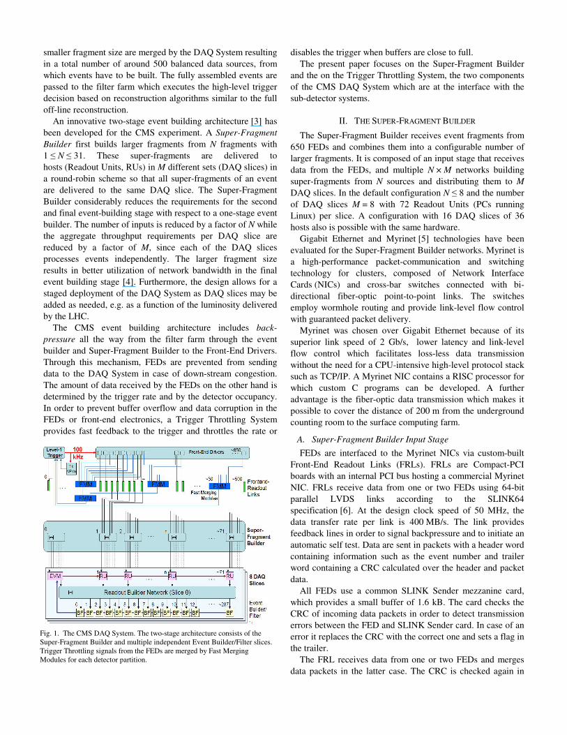
Fig. 1. The CMS DAQ System. The two-stage architecture consists of the Super-Fragment Builder and multiple independent Event Builder/Filter slices. Trigger Throttling signals from the FEDs are merged by Fast Merging Modules for each detector partition.
order to detect transmission errors over the SLINK. Data are buffered in memories of 64 kB size and pushed into the Myrinet NIC in fixed size packets via the internal 64bit/66MHz PCI bus. The FRL provides extensive monitoring capabilities such as histograms of fragment size distribution or the possibility to spy on events.
B. Super-Fragment Builder Network
Each Myrinet NIC contains two bi-directional optical data ports with 2 Gb/s link speed (250 MB/s bandwidth), which are connected to two independent Myrinet switch fabrics. This two-rail configuration doubles the bandwidth to 4 Gb/s per FRL and provides redundancy.
The Myrinet NICs on the FRLs are programmed to send packets to a destination address assigned on the basis of the event number and a look-up-table. The algorithm provides load balancing over the two rails as well as re-transmission in the rare case of packet loss or corruption due to hardware failure. The Myrinet NICs hosted by the Readout Units concatenate fragments with the same event number in order to build the super-fragment.
Instead of using an individual N × M switch for each super-fragment, a single large switch fabric is used per rail. This has the advantage that the composition of super-fragments can easily be reconfigured in order to balance super-fragment size or to route avoiding faulty hardware.
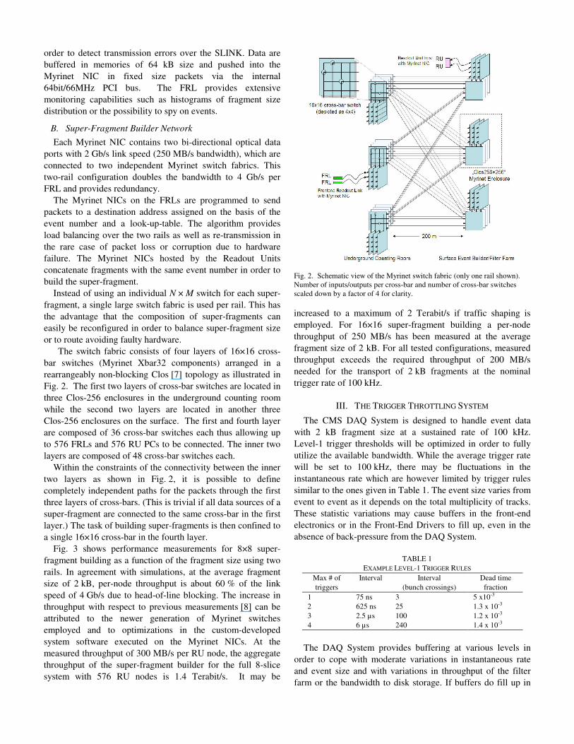
The switch fabric consists of four layers of 16×16 cross-bar switches (Myrinet Xbar32 components) arranged in a rearrangeably non-blocking Clos [7] topology as illustrated in Fig. 2. The first two layers of cross-bar switches are located in three Clos-256 enclosures in the underground counting room while the second two layers are located in another three Clos-256 enclosures on the surface. The first and fourth layer are composed of 36 cross-bar switches each thus allowing up to 576 FRLs and 576 RU PCs to be connected. The inner two layers are composed of 48 cross-bar switches each.
Within the constraints of the connectivity between the inner two layers as shown in Fig. 2, it is possible to define completely independent paths for the packets through the first three layers of cross-bars. (This is trivial if all data sources of a super-fragment are connected to the same cross-bar in the first layer.) The task of building super-fragments is then confined to a single 16×16 cross-bar in the fourth layer.
Fig. 3 shows performance measurements for 8×8 super-fragment building as a function of the fragment size using two rails. In agreement with simulations, at the average fragment size of 2 kB, per-node throughput is about 60 % of the linkspeed of 4 Gb/s due to head-of-line blocking. The increase in throughput with respect to previous measurements [8] can be attributed to the newer generation of Myrinet switches employed and to optimizations in the custom-developed system software executed on the Myrinet NICs. At the measured throughput of 300 MB/s per RU node, the aggregate throughput of the super-fragment builder for the full 8-slice system with 576 RU nodes is 1.4 Terabit/s. It may be
increased to a maximum of 2 Terabit/s if traffic shaping is employed. For 16×16 super-fragment building a per-node throughput of 250 MB/s has been measured at the average fragment size of 2 kB. For all tested configurations, measured throughput exceeds the required throughput of 200 MB/s needed for the transport of 2 kB fragments at the nominal trigger rate of 100 kHz.
III. THE TRIGGER THROTTLING SYSTEM
The CMS DAQ System is designed to handle event data with 2 kB fragment size at a sustained rate of 100 kHz. Level-1 trigger thresholds will be optimized in order to fully utilize the available bandwidth. While the average trigger rate will be set to 100 kHz, there may be fluctuations in the instantaneous rate which are however limited by trigger rules similar to the ones given in Table 1. The event size varies from event to event as it depends on the total multiplicity of tracks. These statistic variations may cause buffers in the front-end electronics or in the Front-End Drivers to fill up, even in the absence of back-pressure from the DAQ System.
TABLE 1EXAMPLE LEVEL-1 TRIGGER RULES
Max # of triggers
Interval Interval(bunch crossings)
Dead time fraction
1 75 ns 3 5 x10⁻³ 2 625 ns 25 1.3 x 10⁻³ 3 2.5 µs 100 1.2 x 10⁻³ 4 6 µs 240 1.4 x 10⁻³
The DAQ System provides buffering at various levels in order to cope with moderate variations in instantaneous rate and event size and with variations in throughput of the filter farm or the bandwidth to disk storage. If buffers do fill up in
Fig. 2. Schematic view of the Myrinet switch fabric (only one rail shown). Number of inputs/outputs per cross-bar and number of cross-bar switches scaled down by a factor of 4 for clarity.

the DAQ System, backpressure will be propagated all the way to the Front-End Drivers, thus constituting a further reason for buffers in the FEDs to fill up.
Buffer overflows, which would result in data corruption and would require a lengthy re-sync operation to recover, are avoided by the synchronous Trigger Throttling System (Fig.1). It provides hardwired feed-back path with a latency of less than 1 µs from each of the 650 FEDs to the Level-1 Trigger.Each FED provides a 4-bit status signal indicating one of the states Ready, Warning, Busy, Out-of-Sync, Error or Disconnected (in order of increasing priority). Signals are transmitted over 4 LVDS pairs. The states Ready, Warning and Busy indicate the amount of buffering left and whether the trigger needs to be throttled or disabled. Given the trigger rules in Table 1 and a TTS latency of 1 µs, a FED has to be able to accept 3 more triggers after it changes into state Busy.
In case of the tracker sub-detector, buffer space in the front-end chips is very limited. Since these chips are mounted directly on the detector, feedback signals would have to travel an additional distance to the underground counting room. In order to shorten the feedback loop and save buffer space in the front-ends, dedicated emulator modules have been designed. These modules, which are located in close proximity to the Level-1 Trigger, receive the triggers, emulate the buffer levels of the front-end-chips and send fast feedback signals directly to the trigger with a control loop latency of only 0.25 µs [9].
The state Out-Of-Sync indicates that synchronization was lost, possibly due to an extremely large event. The state Error indicates an error occurred in the front-end electronics. The Level-1-Trigger attempts to recover automatically from these
states by issuing a Level-1-Resync or Level-1 Reset command via the Timing, Trigger and Control (TTC) System.
For maximum flexibility, FEDs are grouped into 32 TTC partitions which may be operated independent of each other.The Level-1 Trigger Control System separately distributes triggers to these 32 TTC partitions and separately receivestrigger throttling signals for each TTC partition. TTS signals from all FEDs in a TTC partition thus need to be merged with low latency. Dedicated Fast Merging Modules (FMMs) have been designed for this task. These modules can merge and monitor up to 20 inputs and have quad outputs. Optionally, FMMs can be configured to merge two independent groups of 10 inputs with two independent twin outputs. For partitions with more than 20 FEDs, FMMs are cascaded in two layers.
The FMM is a custom-built Compact PCI card. Its main components are a PCI Interface FPGA, a Main Logic FPGA and an on-board memory block. Input signals are sampled with 80 MHz and filtered by requiring two successive samples in the same state. The input signals are then merged by selecting the highest priority input signal from the enabled inputs according to the aforementioned signal priorities. Optionally, Out-of-Sync input signals are only taken into account if the number of inputs in Out-of-Sync state exceeds a programmable threshold. The FMM also provides extensive monitoring capabilities in order to diagnose the causes for dead-times. Each state transition at the inputs is detected and stored with a time-stamp (25 ns resolution) in a history memory that can hold up to 128k transitions. Dead-times, i.e. times spent in the states Warning and Busy are counted with 25 ns resolution for each input channel and for the output(s). FMMs are configured, controlled and monitored by a PC via the Compact-PCI bus. Around 60 FMM modules are needed in order to merge the TTS signals of all TTC partitions of CMS.
A separate asynchronous Trigger Throttling System defines a two-way communication path between the Level-1 Trigger Control System and the DAQ System using the same type of signals as the synchronous TTS. For each of up to 8 groups of TTC partitions defined in the Trigger Control System, the trigger control system sends the state of the group to the DAQ System. The DAQ System sends a TTS signal per group in order to throttle or disable triggers or to resynchronize or reset the group in case of synchronization problems detected by the filter farm. Asynchronous TTS signals are sent and received by the DAQ System using a modified FMM card with 12 inputs and 12 outputs.
IV. THE MAGNET TEST AND COSMIC CHALLENGE
The Magnet Test and Cosmic Challenge (MTCC) in the second half of 2006 was a major milestone towards the completion of CMS. The entire detector was successfully closed for the first time with the solenoid magnet and parts of most sub-detectors installed. Sub-detectors were connected to the front-end electronics and FEDs and interfaced to aprototype of the DAQ System.
Despite the fact that the number of FEDs and the trigger rate
Fig. 3. Super-Fragment Builder throughput per input node as a function of fragment size for 8×8 super-fragment building with a Myrinet Clos-256 switch. For constant size fragments (square markers) the Super-Fragment Builder falls into a barrel-shifter mode which optimally uses bandwidth when fragment size is equal to a multiple of the packet size of 4 kB. This mode may be exploited in the future to increase throughput.
were two to three orders of magnitude smaller than in the final system, the MTCC was an important test for the CMS DAQ System. All types of hardware components and prototypes of all software components of the final DAQ System were tested and integrated with FEDs of all but three of the CMS sub-detectors.
A total number of 18 FEDs of 7 subsystems were connected to the DAQ system as detailed in Table 2. One super-fragment was built per subsystem and processed by a single DAQ Slice with 7 RU hosts. The Super-Fragment-Builder System consisted of 18 input elements (SLINK sender card + SLINKcable + FRL + Myrinet NIC), two Clos-256 Myrinet enclosures and 7 RU PCs equipped with Myrinet NICs. The Myrinet enclosures were equipped with a switch fabric that also supported larger scale performance tests with up to 64 FRLs and up to 64 RU PCs: the first and fourth layer of the switch fabric consisted of 8 cross-bars switches each supporting 2 rails with 64 inputs and 64 outputs. The secondand third layer consisted of 16 cross-bars each with half of the outputs of each second layer cross-bar connected to half of the inputs of a third layer cross-bar.
The Trigger Throttling System consisted of 6 Fast Merging Modules, one for each sub-system (except for the trigger) and an emulator module for the tracker sub-system. The outputs of the 6 FMMs were merged by a merger FMM in order to be able to use a Local Trigger Controller instead of the final Level-1 Trigger, which became available only during the final phase of the test.
In the first phase of the test, each sub-detector was individually integrated with the DAQ system, verifying correct reset of the event counter at the start of a run, correct data
transmission without CRC errors at reduced rate, correct handling of back-pressure applied through the SLINK and correct generation of TTS signals. All problems found during these first integration tests were resolved by modifications to front-end and FED firmware. For some sub-detectors, support for operation at the full Level-1 trigger rate of 100 kHz is still being finalized. Trigger rate during the MTCC was limited since no high-level event filtering was available and therefore all events were stored to disk. The prototype storage manager had a maximum throughput of 40 MB/s limiting the trigger rate to approximately 200 Hz. This mode of operation was supported by all participating sub-detectors thus allowing data to be read out and events to be built.
TABLE 2NUMBER OF SLINKS, FRLS AND TTS CHANNELS IN THE MTCC SETUP
AND THE FINAL CMS DAQ SYSTEM
(CSC: CATHODE STRIP CHAMBER SYSTEM, TF: TRACK FINDER, HCAL: HADRONIC CALORIMETER, ECAL: ELECTROMAGNETIC
CALORIMETER,DT: DRIFT TUBE SYSTEM, RPC: RESISTIVE PLATE CHAMBER SYSTEM)
MTCC Final SystemSub-system # SLINK/FRL #TTS # SLINK #FRL #TTSTrigger 1 - 3 2 1CSC+TF 3 7 9 9 53HCAL 6 6 32 32 32ECAL 2 2 54 54 58Tracker 4 4 440 250 440DT+TF 1 1 6 6 6RPC 1 1 3 3 3Pixel - - 40 40 40Pre-shower - - 56 56 56Totem - - 24 24 25Total 18 21 667 476 714
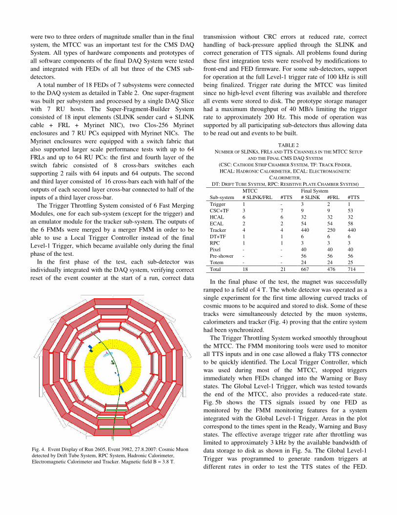
In the final phase of the test, the magnet was successfully ramped to a field of 4 T. The whole detector was operated as a single experiment for the first time allowing curved tracks of cosmic muons to be acquired and stored to disk. Some of these tracks were simultaneously detected by the muon systems, calorimeters and tracker (Fig. 4) proving that the entire system had been synchronized.
The Trigger Throttling System worked smoothly throughout the MTCC. The FMM monitoring tools were used to monitor all TTS inputs and in one case allowed a flaky TTS connector to be quickly identified. The Local Trigger Controller, which was used during most of the MTCC, stopped triggers immediately when FEDs changed into the Warning or Busy states. The Global Level-1 Trigger, which was tested towards the end of the MTCC, also provides a reduced-rate state. Fig. 5b shows the TTS signals issued by one FED as monitored by the FMM monitoring features for a system integrated with the Global Level-1 Trigger. Areas in the plot correspond to the times spent in the Ready, Warning and Busy states. The effective average trigger rate after throttling was limited to approximately 3 kHz by the available bandwidth of data storage to disk as shown in Fig. 5a. The Global Level-1 Trigger was programmed to generate random triggers at
FdE
ig. 4. Event Display of Run 2605, Event 3982, 27.8.2007: Cosmic Muon etected by Drift Tube System, RPC System, Hadronic Calorimeter, lectromagnetic Calorimeter and Tracker. Magnetic field B = 3.8 T.
different rates in order to test the TTS states of the FED.

Depending on the input trigger rate, the FED’s TTS state stayed at Ready, changed between Ready and Warning or changed between Warning and Busy, the latter being the most efficient mode of operation. At trigger rates around 2.8 kHz the TTS state changed between all the three states. The frequency of transitions between TTS states varied as a function of the input trigger rate as shown in Fig. 5c.
V. INSTALLATION AND COMMISSIONING
Since the second half of 2006, the focus of work has shifted towards the installation and commissioning of the final CMS DAQ System in the underground counting room and the surface computing center.
Around 670 SLINK cables and around 500 FRLs housed in 44 Compact-PCI crates have been installed. A total of 38 km of optic fibers were installed connecting the FRLs to the Myrinet enclosures in the underground counting room. All 12 Myrinet enclosures have been installed and 768 pairs of fibers of 200 m length have been installed between the enclosures in the underground counting room and those in the surface event builder farm. Readout Unit PCs in the surface event builder farm are being installed at the time of writing. Around 750 shielded TTS cables and around 60 FMMs housed in 8Compact-PCI crates have been installed in the underground counting room.
SLINK and TTS cables in the underground counting room have been tested with a mobile FED emulator board. A few thousand cycles of test patterns have been sent over each link. Besides identifying a small number bad contacts or soldering problems, this test also served to verify the correct labeling
and routing of the cables.In a second stage, FEDs were installed and SLINK and TTS
cables were connected. For the SLINKs a self-test was initiated by the FRLs requiring only that the SLINK sendercards on the FEDs were powered. For the Trigger Throttling System an automatic in-situ test procedure has been devised. This procedure is executed under the control of the CMS Run Control System and may be repeated at any time in the future on a regular basis or if problems are suspected. One after the other, FEDs are instructed to generate certain TTS signals or sequences of TTS signals. These are then captured by the FMM transition history memories and verified. FED Installation and test of connectivity to the DAQ System are ongoing at the time of writing.
VI. SUMMARY
The CMS Super-Fragment Builder based on Myrinet and the Trigger Throttling System have been presented.Performance measurements show a throughput of 300 MB/s per node for 8×8 super-fragment building, exceeding the required throughput of 200 MB/s per node. Installation of both systems is now close to completion. All hardware and software components and their interfaces to most of the sub-detectors have successfully been tested during the Magnet Test and Cosmic Challenge at the end of 2006. Commissioning of the full-scale system is underway and will continue over the next few months in order to be ready for the first LHC collisions at the end of the 2007.
REFERENCES
[1] The CMS Collaboration, CMS Technical Proposal, CERN LHCC 94-38, 1994.
[2] The CMS Collaboration, CMS, The TriDAS Project, Technical DesignReport, Volume 1: The Trigger Systems, CERN/LHCC 2000-38, 2000.
[3] The CMS Collaboration, CMS, The TriDAS Project, Technical Design Report, Volume 2: Data Acquisition and High-Level Trigger,CERN/LHCC 2002-26, 2002.
[4] M. Pieri et al., “CMS DAQ Event Builder Based on Gigabit Ethernet,” prepared for International Conference on Computing in High Energy and Nuclear Physics (CHEP 2006), Mumbai, Maharashtra, India, 13-17 Feb 2006.
[5] Myricom, see http://www.myri.com[6] A. Racz, R. McLaren, E. van der Bij, The S-Link 64 bit Extension
Specification: S-Link64, available at http://hsi.web.cern.ch/HSI/s-link[7] C. Clos, "A study of non-blocking switching networks," Bell System
Technical Journal, vol. 32, March 1953, pp. 406–424.[8] R. Arcidiacono et al., “The 2 Tbps ‘Data to Surface’ system of the CMS
Data Acquisition,” in Real Time Conference, 2005, 14th IEEE-NPSS,Montreal, 2005.
[9] G. Iles, W. Cameron, C. Foudas, G. Hall, N. Marinelli, “The APVE emulator to prevent front-end buffer overflows within the CMS Silicon Strip Tracker,” in Electronics for LHC Experiments, Colmar, 2002,pp. 396-399.
Fig. 5. TTS Monitoring for Run 4517. The Level-1 Global Trigger was programmed to generate random triggers at different rates (not shown) which were distributed to a Front-End Driver. At trigger rates greater than 2800 Hz the FED received back-pressure from the DAQ System and requested to throttle (TTS state Warning) or stop (TTS state Busy) the trigger. Plot a) shows the effective trigger rate as distributed by the Level-1 Global Trigger. Plot b) shows the fractions of time spent in TTS states Ready (solid), Warning (hatched) and Busy (cross-hatched) as monitored by the FMM. Plot c) shows the rate of transitions between TTS states.