5 Port Pilot Operated Solenoid Valve - SMC CORPORATION
131
5 (R1) 3 (R2) 1 (P) (A)4 2(B) 3 (R2) 5 (R1) 1 (P) 2(B) (A)4 (A)4 2(B) 3 (R2) 1 (P) 5 (R1) (A)4 2(B) 3 (R2) 1 (P) 5 (R1) (A)4 2(B) 3 (R2) 1 (P) 5 (R1) (A)4 2(B) 3 (R2) 1 (P) 5 (R1) (A)4 2(B) 3 (R2) 1 (P) 5 (R1) (A)4 2(B) 3 (R2) 1 (P) 5 (R1) (A)4 2(B) 3 (R2) 1 (P) 5 (R1) 3 (R2) 5 (R1) 1 (P) 2(B) (A)4 3 (R1) 5 (R2) 1 (P) (A)4 2(B) 3 (R2) 5 (R1) 1 (P) 2(B) (A)4 5 (R1) 3 (R2) 1 (P) (A)4 2(B) VFS1000/2000/3000/4000/5000/6000 Series 5 Port Pilot Operated Solenoid Valve Metal Seal [Option] Series Type of actuation Voltage Electrical entry With light/surge voltage suppressor (Option) Manual override VFS1000 (P.886) VFS2000 (P.894) VFS3000 (P.902) Grommet Grommet terminal (E) Conduit terminal (T) DIN terminal (D) VFS2000 Plug-in type Non plug-in type (P.914) VFS3000 Plug-in type Non plug-in type (P.940) VFS4000 Plug-in type Non plug-in type (P.962) VFS5000 Plug-in type Non plug-in type (P.982) VFS6000 Plug-in type Non plug-in type (P.998) 3 position Single Double 1.8 1.8 3.4 3.4 6.8 6.5 2.8 2.7 5.8 5.4 12 11 20 17 38 — 2 position single 2 position double 3 position closed center 3 position exhaust center 3 position pressure center 2 position single 2 position double 2 position single 2 position double 3 position closed center 3 position exhaust center 3 position pressure center 3 position double check Sonic conductance C [dm 3 /s·bar)] 4/2 5/3(A/B R1/R2) Body Ported Series Variations (Standard) 100 VAC, 50/60 Hz 200 VAC, 50/60 Hz 24 VDC (Semi-standard) 110 to 120 VAC, 50/60 Hz 220 VAC, 50/60 Hz 240 VAC, 50/60 Hz 12 VDC 100 VDC (G) With light/surge voltage suppressor • Grommet terminal (EZ) • Conduit terminal (TZ) • DIN terminal (DZ) With surge voltage suppressor • Grommet (GS) Note) • Indicator light is not available for grommet type. Only surge voltage suppressor can be equipped on the middle of lead wire. • DC: There is polarity. (Lead wire Red: +, Black: –) Non-locking push type (Flush) Non-locking push type (Extended) Locking type (Tool required) Locking type ∗ (Lever) ∗ Locking type (lever) is not available for body ported VFS2000/3000 series. Non-locking push type (Flush) Non-locking push type (Flush) Non-locking push type (Extended) Locking type (Tool required) Locking type (Lever) (Standard) 100 VAC, 50/60 Hz 200 VAC, 50/60 Hz 24 VDC (Semi-standard) 110 to 120 VAC, 50/60 Hz 220 VAC, 50/60 Hz 240 VAC, 50/60 Hz 12 VDC 100 VDC Conduit terminal (F) Grommet terminal (E) Grommet (G) Plug-in Non plug-in Conduit terminal (T) DIN terminal (D) DIN terminal (D) Grommet terminal (E) Non plug-in Conduit terminal (F) Plug-in DIN terminal (D) Conduit terminal (F) Grommet terminal (E) Plug-in Non plug-in With light/surge voltage suppressor • Plug-in type Conduit terminal (FZ) • Non plug-in type Grommet terminal (EZ) Conduit terminal (TZ) DIN terminal (DZ) Note) • Indicator light is not available for grommet type. Only surge voltage suppressor can be equipped on the middle of lead wire. • DC: There is polarity. (Lead wire Red: +, Black: –) With surge voltage suppressor • Non plug-in type Grommet (GS) With light/surge voltage suppressor • Plug-in type Conduit terminal (FZ) • Non plug-in type Grommet terminal (EZ) DIN terminal (DZ) Base Mounted 883 SV SYJ SZ VF VP4 VQ 1/2 VQ 4/5 VQC 1/2 VQC 4/5 VQZ SQ VFR VQ7 VFS
-
Upload
khangminh22 -
Category
Documents
-
view
0 -
download
0
Transcript of 5 Port Pilot Operated Solenoid Valve - SMC CORPORATION

5(R1)
3(R2)
1(P)
(A)4 2(B)
3(R2)
5(R1)
1(P)
2(B)(A)4
(A)4 2(B)
3(R2)
1(P)
5(R1)
(A)4 2(B)
3(R2)
1(P)
5(R1)
(A)4 2(B)
3(R2)
1(P)
5(R1)
(A)4 2(B)
3(R2)
1(P)
5(R1)
(A)4 2(B)
3(R2)
1(P)
5(R1)
(A)4 2(B)
3(R2)
1(P)
5(R1)
(A)4 2(B)
3(R2)
1(P)
5(R1)
3(R2)
5(R1)
1(P)
2(B)(A)4
3(R1)
5(R2)
1(P)
(A)4 2(B)
3(R2)
5(R1)
1(P)
2(B)(A)4
5(R1)
3(R2)
1(P)
(A)4 2(B)
VFS1000/2000/3000/4000/5000/6000 Series
5 Port Pilot Operated Solenoid Valve
Metal Seal
[Option]
Series Type of actuation
Voltage Electrical entry With light/surgevoltage suppressor
(Option)
Manualoverride
VFS1000(P.886)
VFS2000(P.894)
VFS3000(P.902)
Grommet Grommet terminal (E)
Conduit terminal (T)
DIN terminal (D)
VFS2000Plug-in type
Non plug-in type(P.914)
VFS3000Plug-in type
Non plug-in type(P.940)
VFS4000Plug-in type
Non plug-in type(P.962)
VFS5000Plug-in type
Non plug-in type(P.982)
VFS6000Plug-in type
Non plug-in type(P.998)
3position
SingleDouble
1.8 1.8
3.4 3.4
6.8 6.5
2.8 2.7
5.8 5.4
12 11
20 17
38 —
2 position single
2 position double
3 position closed center
3 position exhaust center
3 position pressure center
2 position single
2 position double
2 position single
2 position double
3 position closed center
3 position exhaust center
3 position pressure center
3 position double check
Sonic conductanceC [dm3/s·bar)]
4/2 5/3(A/B R1/R2)
Bo
dy
Po
rted
Series Variations
(Standard)
100 VAC, 50/60 Hz200 VAC, 50/60 Hz24 VDC
(Semi-standard)
110 to 120 VAC, 50/60 Hz220 VAC, 50/60 Hz240 VAC, 50/60 Hz 12 VDC100 VDC
(G) With light/surge voltage suppressor
• Grommet terminal (EZ)• Conduit terminal (TZ)• DIN terminal (DZ)
With surge voltage suppressor
• Grommet (GS)
Note) • Indicator light is not available for grommet type. Only surge voltage suppressor can be equipped on the middle of lead wire.
• DC: There is polarity.(Lead wireRed: +, Black: –)
Non-lockingpush type(Flush)
Non-lockingpush type(Extended)
Locking type(Tool required)
Locking type ∗(Lever)
∗ Locking type (lever) is not available for body ported VFS2000/3000 series.
Non-lockingpush type(Flush)
Non-lockingpush type(Flush)
Non-lockingpush type(Extended)
Locking type(Tool required)
Locking type(Lever)
(Standard)
100 VAC, 50/60 Hz200 VAC, 50/60 Hz24 VDC
(Semi-standard)
110 to 120 VAC, 50/60 Hz220 VAC, 50/60 Hz240 VAC, 50/60 Hz 12 VDC100 VDC
Conduitterminal (F)
Grommetterminal (E)Grommet (G)
Plug-in
Non plug-in
Conduitterminal (T)
DIN terminal(D)
DINterminal (D)
Grommetterminal (E)
Non plug-in
Conduitterminal (F)
Plug-in
DIN terminal (D)
Conduitterminal (F)
Grommetterminal (E)
Plug-in
Non plug-in
With light/surge voltagesuppressor• Plug-in typeConduit terminal (FZ)
• Non plug-in typeGrommet terminal (EZ)Conduit terminal (TZ)DIN terminal (DZ)
Note) • Indicator light is not available for grommet type. Only surge voltage suppressor can be equipped on the middle of lead wire.
• DC: There is polarity.(Lead wireRed: +, Black: –)
With surge voltage suppressor• Non plug-in typeGrommet (GS)
With light/surge voltagesuppressor
• Plug-in typeConduit terminal (FZ)
• Non plug-in typeGrommet terminal (EZ)DIN terminal (DZ)
Bas
e M
ou
nte
d
883
SV
SYJ
SZ
VF
VP4VQ1/2
VQ4/5
VQC1/2
VQC4/5
VQZ
SQ
VFS
VFR
VQ7
VFS

Manifold
(P.891)
(P.899)
(P.908)
(P.922) (P.922) (P.922) (P.923)
(P.946) (P.946) (P.946)
(P.968) (P.968) (P.968)
(P.988) (P.988) (P.988)
(P.923)
(P.946)
(P.968)
(P.988)
VFS1000
VFS2000
VFS3000
VFS2000
VFS3000
VFS4000
VFS5000
VFS2000
VFS3000
VFS4000
VFS5000
Manifold Variations
Barbase
Stackingbase
∗ Bottom piping is available as an option.
Withattachment
plug lead wire
Withterminal
block
Withmulti-
connector
WithD-sub
connector
Non plug-in(Connection to
each valve)
Body
Por
ted
Bar Base(VFS1000/2000 series)
Plug-in
Non Plug-in
Stacking base(VFS3000 series)
Pilot individual EXH
Pilot common EXH
Pilot common EXH
With attachment plug lead wire
With multi-connector
With terminal block
With D-sub connector
Grommet terminal DIN terminal
Base
Mou
nted
Plu
g-i
n T
ype
Base
Mou
nted
No
n P
lug
-in
Typ
e
884
VFS Series
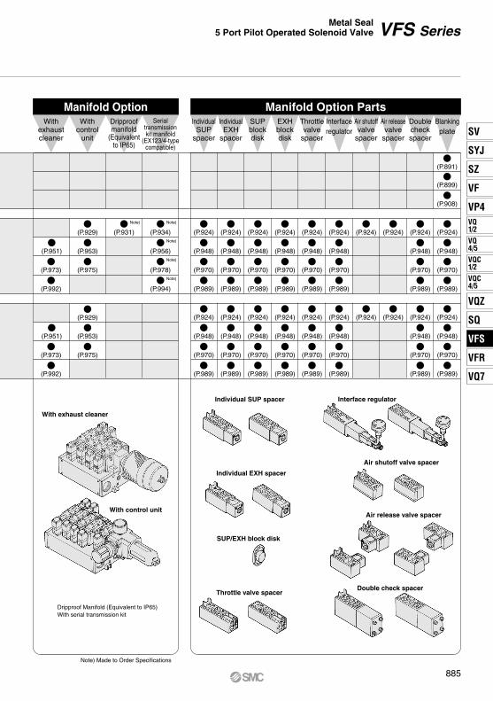
Manifold Option Manifold Option PartsWith
exhaustcleaner
(P.934)
(P.908)
(P.899)
(P.891)
Note)(P.931)
Note)
Note)
Note)
Note)
(P.956)
(P.978)
(P.929)
(P.953)
(P.975)
(P.951)
(P.973)
(P.992)
(P.929)
(P.953)
(P.975)
(P.951)
(P.973)
(P.992)
(P.994)
(P.924)
(P.948)
(P.970)
(P.989)
(P.924)
(P.948)
(P.970)
(P.989)
(P.924)
(P.948)
(P.970)
(P.989)
(P.924)
(P.948)
(P.970)
(P.989)
(P.924)
(P.948)
(P.970)
(P.989)
(P.924)
(P.948)
(P.970)
(P.989)
(P.924)
(P.948)
(P.970)
(P.989)
(P.924)
(P.924)
(P.924)
(P.948)
(P.970)
(P.989)
(P.924)
(P.948)
(P.970)
(P.989)
(P.924)
(P.948)
(P.970)
(P.989)
(P.924)
(P.948)
(P.970)
(P.989)
(P.924)
(P.948)
(P.970)
(P.989)
(P.924)
(P.948)
(P.970)
(P.989)
(P.924)
(P.948)
(P.970)
(P.989)
(P.924)
(P.924)
(P.924)
(P.948)
(P.970)
(P.989)
(P.924)
(P.948)
(P.970)
(P.989)
Serialtransmissionkit manifold
(EX123/4-typecompatible)
IndividualSUP
spacer
IndividualEXH
spacer
SUPblockdisk
EXHblockdisk
Throttlevalve
spacer
Interfaceregulator
Air shutoffvalve
spacer
Air releasevalve
spacer
Doublecheckspacer
Blankingplate
Withcontrol
unit
Dripproofmanifold
(Equivalentto IP65)
With exhaust cleaner
With control unit
Individual SUP spacer Interface regulator
Individual EXH spacer
Air shutoff valve spacer
SUP/EXH block disk
Throttle valve spacer
Air release valve spacer
Double check spacer
Note) Made to Order Specifications
Dripproof Manifold (Equivalent to IP65)With serial transmission kit
885
VFS SeriesMetal Seal
5 Port Pilot Operated Solenoid Valve
SV
SYJ
SZ
VF
VP4VQ1/2
VQ4/5
VQC1/2
VQC4/5
VQZ
SQ
VFS
VFR
VQ7
VFS

VFS1000 series is compatible with the old models, VF220 and VF230 series.
(A)4 2(B)
3(R2)
1(P)
5(R1)
3(R2)
5(R1)
1(P)
2(B)(A)4
(A)4 2(B)
3(R2)
1(P)
5(R1)
(A)4 2(B)
3(R2)
1(P)
5(R1)
5(R1)
3(R2)
1(P)
(A)4 2(B)
[Option]
ModelType of actuation
VFS1120
VFS1220
VFS1320
VFS1420
VFS1520
VFS1130 1.7
1.7
1.6
1.7
1.7
0.22
0.22
0.20
0.18
0.24
0.38
0.39
0.37
0.38
0.40
0.19
0.19
0.20
0.19
0.18
0.40
0.40
0.41
0.44
0.37
1.8
1.8
1.8
1.9
1.6
VFS1230
VFS1330
VFS1430
VFS1530
Portsize
1200
1200
600
600
600
0.18
0.26
0.27
0.27
0.27
Note 1) Based on JIS B 8419: 2010 (once per 30 days) for the minimum operating frequency.Note 2) Based on JIS B 8419-2010. (The value at supply pressure 0.5 MPa, ambient/fluid temperature (≈ 20°C))
However, this excludes when in an adhered state. (Be aware that after long periods of holding time, there may be delays in the initial response time.)Note 3) In the case of grommet typeNote 4) “Note 1)” and “Note 2)” are with controlled clean air.
C[dm3/(s·bar)] b Cv
C[dm3/(s·bar)] b Cv
1 4/2 (P A/B) 4/2 5/3 (A/B R1/R2)Flow rate characteristics
1 8
1 8
1 8
1 8
1 8
Model
Standard Specifications
Option Specifications
Symbol
Manifold
Pilot valve manual override
Coil rated voltage
Foot bracket (With screw)
110 to 120, 220, 240 VAC (50/60 Hz)Non-locking push type (Extended), Locking type (Tool required), Locking type (Lever)
12, 100 VDCOption With light/surge voltage suppressor Note)
Part No.: AXT626-10A, VFS1120 (single) only
Body type
VFS130VFS120
Bar manifold (Common EXH base side)Bar manifold (Individual EXH)
Applicable manifold base (Pilot EXH)
2 position 3 positionSingle Closed center
Double Exhaust center
Pressure center
VFS1320-D-01
VFS1120-G-01-F
VFS1120-G-01
VFS1220-E-01
Compact yet provides a large flow capacityC: 1.8 dm3/(s·bar)Low power consumption: 1.8 W DC
2 po
sitio
n3
posi
tion
Single
Double
Closedcenter
Pressure center
Exhaust center
Max. operating
cycle(cpm)
Responsetime(ms)
Weight(kg)
15 or less
13 or less
20 or less
20 or less
20 or less
FluidMaximum operating pressure
InrushHolding
2 position3 position
Min. operating pressure
Ambient and fluid temperatureProof pressure
LubricationPilot valve manual overrideImpact/Vibration resistance EnclosureCoil rated voltageAllowable voltage fluctuationCoil insulation typeApparent power(Power consumption)
Electrical entry
Air1.0 MPa0.1 MPa0.15 MPa
–10 to 60°C (1)
Non-lube (2) Non-locking push type (Flush)
150/50 m/s2 (3)
Dustproof (Equivalent to IP50) (4)
100, 200 VAC, 50/60 Hz; 24 VDC–15 to +10% of rated voltage
5.6 VA (50 Hz), 5.0 VA (60 Hz)3.4 VA (2.1 W)/50 Hz, 2.3 VA (1.5 W)/60 Hz
Grommet, Grommet terminal,Conduit terminal, DIN terminal
1.5 MPa
Class B or equivalent (130°C) (5)
1.8 W (2.04 W: With light/surge voltage suppressor)Power consumption (DC)
Note 1) Use dry air at low temperatures.Note 2) Use turbine oil Class 1 (ISO VG32), if lubricated.Note 3) Impact resistance: No malfunction occurred when it is tested with a drop tester in the axial direction
and at the right angles to the main valve and armature in both energized and de-energized states every once for each condition. (Values at the initial period)
Vibration resistance: No malfunction occurred in a one-sweep test between 45 and 2000 Hz. Test was performed at both energized and de-energized states in the axial direction and at the right angles to the main valve and armature. (Values at the initial period)
Note 4) Based on JIS C 0920. Note 5) Based on JIS C 4003.
Val
ve s
pec
ific
atio
ns
Elec
tric
ity s
peci
ficat
ions
AC
Note) Grommet type is available only w/ surge voltage suppressor (which is directly connected with lead wire).
Note) VFS130: Manifold only. Cannot be used as a single unit.
(1)(2)
(3)
886
5 Port Pilot Operated Solenoid ValveMetal Seal, Body Ported
VFS1000 Series
A

Note) No mounting bolts and gaskets are supplied with the valve single unit.
(A)4 2(B)
3(R2)
1(P)
5(R1)
(A)4 2(B)
3(R2)
1(P)
5(R1)
(A)4 2(B)
3(R2)
1(P)
5(R1)
3(R2)
5(R1)
1(P)
2(B)(A)4
5(R1)
3(R2)
1(P)
(A)4 2(B)
01VFS1 1 20Symbol
1
2
3
4
5
Electrical entryBody (Pilot exhaust)
Manual override
Light/Surge voltage suppressor
Option
1 G
Coil rated voltage
Coil rated voltage Manual override21
22
Applicable modelSF4 DZ1 21
Electrical entry, Light/Surge voltage suppressor
How to Order Pilot Valve Assembly
2 position single
2 position double
3 position closed center
3 position exhaust center
3 position pressure center
T: Conduit terminal D, Y: DIN terminalDO, YO: DIN terminal without connector
F: With foot bracket
G: Grommet E: Grommet terminal20: Individual EXH
30∗: Common EXH
Nil: Non-locking push type(Flush)
B∗: Locking type
∗ Semi-standard
∗ Grommet type is available only w/ surge voltage suppressor, not w/ indicator light.
Nil Z
NoneWith light/surge voltage suppressor
With surge voltage suppressor
01 1 8
Port sizeNilN∗
RcNPT
NPTFG
T∗
F∗
∗ Semi-standard
Thread type
∗ Semi-standardFor other rated voltages, please consult with SMC.
∗ Manifold only
∗ Mountable only for VFS1120.
3∗21
4∗
6∗5
7∗
100 VAC (50/60 Hz)200 VAC (50/60 Hz)
110 to 120 VAC (50/60 Hz)220 VAC (50/60 Hz)
24 VDC12 VDC
240 VAC (50/60 Hz)
1 100 VAC, 50/60 Hz2 200 VAC, 50/60 Hz3∗ 110 to 120 VAC (50/60 Hz)4∗ 220 VAC, 50/60 Hz5 24 VDC6∗ 12 VDC7∗ 240 VAC, 50/60 Hz
∗ Semi-standardFor other rated voltages, please consult with SMC.
∗ Semi-standard
Nil
B∗
A∗
C∗
Non-locking pushtype (Flush)
Non-locking pushtype (Extended)
Locking type(Tool required)Locking type
(Lever)
Individual pilot exhaust
Common pilot exhaust
For VFS120
For VFS130GGS
GrommetGrommet with surge voltage suppressor
DIN terminalDIN terminal with light/surge voltage suppressor
DDZ
DIN terminal ∗∗DIN terminal with light/surge voltage suppressor ∗∗
DIN terminalDIN terminal with light/surge voltage suppressor
DIN terminal ∗∗DIN terminal with light/surge voltage suppressor ∗∗
DODOZY∗YZ∗YO∗YOZ∗
Conduit terminalConduit terminal with light/surge voltage suppressor
TTZ
Grommet terminalGrommet terminal with light/surge voltage suppressor
EEZ
A∗: Non-locking push type(Extended)
C∗: Locking type (Lever)
How to Order
∗ Y: Conforming to DIN43650B standard∗∗ DIN connector is not attached.
Q
CE-compliantNil —
CE-compliant
S∗
887
VFS1000 Series5 Port Pilot Operated Solenoid Valve
Metal Seal, Body Ported
SV
SYJ
SZ
VF
VP4VQ1/2
VQ4/5
VQC1/2
VQC4/5
VQZ
SQ
VFS
VFR
VQ7
VFS
A

(A)4 2(B)
3(R2)
1(P)
5(R1)
3(R2)
5(R1)
1(P)
2(B)(A)4
(A)4 2(B)
3(R2)
1(P)
5(R1)
(A)4 2(B)
3(R2)
1(P)
5(R1)
5(R1)
3(R2)
1(P)
(A)4 2(B)
VFS1120-01
800700600500400300200100 0
ø6 ø10 ø16 ø20 ø25 ø32 ø40 ø40 ø50 ø63 ø80 ø100
Body Ported
Construction
Body ported CJ2 series CM2 series MB, CA2 series
VFS1120-01
Conditions
23
1
4
———
56 —7 —
———
Component Parts
Cylinder Speed Chart
2 position single 2 position double
3 position closed center/exhaust center/pressure centerClosed center
Exhaust center
Pressure center
Stainless steelReturn springPilot valve assembly Detent assembly
∗ Refer to “How to Order Pilot Valve Assembly” on page 887.
No. Description
Stainless steelResin
MaterialAluminum die-casted
Note
Spool/SleeveBody
End plateResinPiston
—
SeriesAveragespeed(mm/s)
Bore sizeCJ2 seriesPressure 0.5 MPaLoad factor 50%Stroke 60 mm
CM2 seriesPressure 0.5 MPaLoad factor 50%Stroke 300 mm
MB, CA2 seriesPressure 0.5 MPaLoad factor 50%Stroke 500 mm
Perpendicular,upward actuationHorizontalactuation
Use as a guide for selection.Please confirm the actual conditions with SMC Sizing Program.
AN101-01
T0604 x 1 mAS3002F-06
T0806 x 1 mAS3002F-08
Tube bore x LengthSpeed controllerSilencer
∗ It is when the cylinder is extending that is meter-out controlled by speed controller which is directly connected with cylinder, and its needle valve with being fully open.
∗ The average velocity of the cylinder is the value that the stroke is divided by the total stroke time.
∗ Load factor: ((Load mass x 9.8)/Theoretical force) x 100%
888
VFS1000 Series

Y(Z) typeGMN209
CAXT623-6-7-13
D(Z) typeB1B09-2A6
CAXT623-6-7-12Connector
Gasket
DIN Connector/Gasket Part No.
Grommet terminal: VFS1120-E/EZ
Conduit terminal: VFS1120-T/TZ
DIN terminal: VFS1120-D/DZ/Y/YZ
( ): Y, YZ
Foot bracket (F)Part no. : AXT626-10A
2 Position Single — Grommet, Grommet terminal, Conduit terminal, DIN terminal
Grommet : VFS1120-G
Manual overrideNon-locking push type
2 x ø4.5mounting hole
Solenoid valve
2 x ø3.5 mounting hole
≈ 30
0(L
ead
wire
leng
th)
5 x Rc 1/8
Lead wire O.D.Max. ø3.5 Applicable heavy-duty code
O.D. ø6 to ø8(Y: ø4.7 to ø7)
(Locking type)
Pilot EXH(No VFS130)
Manualoverride
2 x ø4.5 mounting hole
M3 x 0.5 x 14LCountersunk head screw
Tightening torque: 0.6 N·m
With light/surge voltage suppressor (EZ)
Light
Manual override(Locking type)
With light/surge voltage suppressor (DZ)
Gasket
Connector
Light
Manual override(Locking type)
Applicable heavy-duty codeO.D. ø6 to ø8
With light/surge voltage suppressor (TZ)
Light
Manual override(Locking type)
Description
889
VFS1000 Series5 Port Pilot Operated Solenoid Valve
Metal Seal, Body Ported
SV
SYJ
SZ
VF
VP4VQ1/2
VQ4/5
VQC1/2
VQC4/5
VQZ
SQ
VFS
VFR
VQ7
VFS

Y(Z) type
GMN209CAXT623-6-7-13
D(Z) type
B1B09-2A6CAXT623-6-7-12
ConnectorGasket
DIN Connector/Gasket Part No.
Gasket
Connector
( ): Y, YZ
2 Position Double, 3 Position — Grommet, Grommet terminal, Conduit terminal, DIN terminal
Grommet: VFS1220-G, VFS1320-G, VFS1420-G, VFS1520-G
DIN terminal : VFS1220-D/DZ/Y/YZ VFS1320-D/DZ/Y/YZ VFS1420-D/DZ/Y/YZ VFS1520-D/DZ/Y/YZ
Grommet terminal: VFS1220-E/EZ VFS1320-E/EZ VFS1420-E/EZ VFS1520-E/EZ
Conduit terminal: VFS1220-T/TZ VFS1320-T/TZ VFS1420-T/TZ VFS1520-T/TZ
2 x ø4.5 mounting hole
151 (3 position: 155.5)
2 x ø3.5 mounting hole
≈ 30
0(L
ead
wire
leng
th)
Pilot EXH(No VFS130)
Lead wire O.D. Max. ø3.5 152 (3 position: 156.5)
Applicable heavy-duty cord O.D. ø6 to ø8 (Y: ø4.7 to ø7)
188 (3 position: 192.5)
188 (3 position: 192.5)
With light/surge voltage suppressor (DZ)
With light/surge voltage suppressor (TZ)
With light/surge voltage suppressor (EZ)
Light
Light
Light
Manual override(Locking type)
Manual override(Locking type)
(Locking type)
Manual override(Locking type)
Applicable heavy-duty cord O.D. ø6 to ø8
Manualoverride
Manual overrideNon-locking push type
Description
890
VFS1000 Series

[Option]
Manifold base typeMax. 15 stations
Bar manifold, Body ported
PassageSymbol Valve
4(A), 2(B)Base
5(R1), 3(R2)Base1(P)
Side/(1/8)5(R1), 3(R2)
Common1(P)
Common1
Porting specifications: Rc (Connecting port size)
Top/(1/8) Side/(1/8)
Blanking plate VVFS1000-10A-1 With gasket, screw
10520 01VFS1000 Series
Manifold
Symbol
Symbol
1
Passage Porting specifications2(B), 4(A)3(R2), 5(R1)1(P)
Common
Stations
Base model
VV5FS1
Model Applicable valve model
20
30
Pilot exhaustPilot individual EXH
VFS120--01
Pilot common EXH
2 stations
15 stations
02
15
01
1 8
Common1 8
Top1 8
VFS130--01
∗VFS120--01mountable
RcNPTNPTF
G
∗ Semi-standard
Thread type
P, EA, EB port size
Specifications
Port Specifications
Option
How to Order Manifold Base
VV5FS1-20
VV5FS1-30
Part no. for mounting bolt and gasket
BG-VFS1030
How to Order Manifold Assembly [Example]
<Example>(Manifold base)(2 position single)(2 position double)(Blanking plate)
Add the valve and option part numbers in order starting from the first station on the D side.
Compact and lightweightCompact due to manifolding on a single base for mounting in small spaces.
Keeps environmental air clean from pilot exhaustUse of the VV5FS1-30 manifold can exhaust intensively the pilot exhaust gas to the base side, and can prevent environmental aggravation due to noise and oil mist.
Stations
••
•
••
1321
VV5FS1-20-061-01VFS1120-1D-01VFS1220-1D-01VVFS1000-10A-1
NilN∗T∗F∗
Q
CE-compliantNil —
CE-compliant
1/8
∗ ∗ ∗
The asterisk denotes the symbol for assembly. Prefix it to the part numbers of the solenoid valve.
•
891
VFS1000 SeriesManifold Specifications Single Base Type
SV
SYJ
SZ
VF
VP4VQ1/2
VQ4/5
VQC1/2
VQC4/5
VQZ
SQ
VFS
VFR
VQ7
VFS
A

Grommet terminal: E/EZ Conduit terminal: T/TZ DIN terminal: D/DZ/Y/YZ
( ): Y, YZ
Formula for manifold weight M = 0.049n + 0.059 (kg) n: Station
n: Station
Grommet: G
Type 20 Manifold — Pilot individual exhaust: VV5FS1-20- 1-01
4 x ø5.2 mounting hole
GasketPilot EXH
Stations
Lead wire O.D.Max. ø3.5
(With light/surge voltage suppressor: 82.5)
(With light/surge voltage suppressor: 91.5)(With light/surge voltage suppressor: 86.5)
(With light/surge voltage suppressor: 96.5)
(With light/surge voltage suppressor: 97.5 (99.5))
(With light/surge voltage suppressor: 106.5 (108.5))
Applicable heavy-duty cordO.D. ø6 to ø8
Applicable heavy-duty cordO.D. ø6 to ø8(Y: ø4.7 to ø7)
3 po
sitio
n (1
56.5
)D
oubl
e (1
52)
Sin
gle
(103
.5)
3 po
sitio
n (1
92.5
)D
oubl
e (1
88)
Sin
gle
(121
.5)
3 po
sitio
n (1
92.5
)D
oubl
e (1
88)
Sin
gle
(121
.5)
3 position Double Single
Blanking plate
Manual override
≈ 300(Lead wire length)
U side D side
25977
SymbolL1
L2
383
101
4107125
5131149
6155173
7179197
8203221
9227245
10251269
FormulaL1 = 24 x n + 11L2 = 24 x n + 29
Stations
Station
892
VFS1000 Series

Grommet terminal: E/EZ Conduit terminal: T/TZ DIN terminal: D/DZ/Y/YZ
( ): Y, YZ
Formula for manifold weight M = 0.079n + 0.093 (kg) n: Station
Grommet: G
25977
SymbolL1
L2
383
101
4107125
5131149
6155173
7179197
8203221
9227245
10251269
FormulaL1 = 24 x n + 11L2 = 24 x n + 29
Stationsn: Station
4 x ø5.2 mounting hole
Gasket
Lead wire O.D.
Stations
3 position Double Single
Pilot EXH port
Pilot EXH port
Blanking plate
Manual override
≈ 300(Lead wire length)
U side D side
3 po
sitio
n (1
56.5
)D
oubl
e (1
52)
Sin
gle
(103
.5)
(With light/surge voltage suppressor: 87.5)
(With light/surge voltage suppressor: 96.5)
Applicable heavy-duty codeO.D. ø6 to ø8
Pilot EXH port
3 po
sitio
n (1
92.5
)D
oubl
e (1
88)
Sin
gle
(121
.5)
(With light/surge voltage suppressor: 91.5)
(With light/surge voltage suppressor: 101.5)
Applicable heavy-duty codeO.D. ø6 to ø8(Y: ø4.7 to ø7)
Pilot EXH port
3 po
sitio
n (1
91.5
)D
oubl
e (1
87)
Sin
gle
(121
)
(With light/surge voltage suppressor: 102.5 (104.5))
(With light/surge voltage suppressor: 111.5 (113.5))
4 x M5
Type 30 Manifold — Pilot common exhaust: VV5FS1-30- 1-01Station
893
VFS1000 Series5 Port Pilot Operated Solenoid Valve
Metal Seal, Body Ported
SV
SYJ
SZ
VF
VP4VQ1/2
VQ4/5
VQC1/2
VQC4/5
VQZ
SQ
VFS
VFR
VQ7
VFS

[Option]
(A)4 2(B)
3(R2)
1(P)
5(R1)
3(R2)
5(R1)
1(P)
2(B)(A)4
(A)4 2(B)
3(R2)
1(P)
5(R1)
(A)4 2(B)
3(R2)
1(P)
5(R1)
5(R1)
3(R2)
1(P)
(A)4 2(B)
1 8
1 8
1 4
1 41 81 41 81 41 81 4
ModelType of actuation
PortsizeRc
1200
1200
600
600
600
22 or less
13 or less
40 or less
40 or less
40 or less
1 4/2 (P A/B) 4/2 5/3 (A/B R1/R2) Flow rate characteristics
VFS2320
VFS2420
VFS2520
VFS2120
VFS2220
3.24.03.24.03.24.03.24.03.14.0
0.240.200.240.200.240.200.250.200.230.24
0.780.900.780.900.780.900.790.900.750.92
3.43.53.43.53.23.43.43.43.33.3
0.280.320.280.320.270.290.260.320.270.30
0.820.850.820.850.800.830.820.840.800.82
VFS2330
VFS2430
VFS2130
VFS2230
VFS2530
0.42
0.42
0.26
0.35
0.42
Model
Standard Specifications
Option Specifications
Manifold
Symbol
VFS2320-T-02
VFS2220-E-02
VFS2120-E-02-F
VFS2120-G-02
2 position 3 positionSingle Closed center
Double Exhaust center
Pressure center
Pilot valve manual override
Coil rated voltage
Foot bracket (With screw)
Pilot type
Option
Note 1) Based on JIS B 8419: 2010 (once per 30 days) for the minimum operating frequency.Note 2) Based on JIS B 8419-2010. (The value at supply pressure 0.5 MPa, ambient/fluid temperature (≈ 20°C))
However, this excludes when in an adhered state. (Be aware that after long periods of holding time, there may be delays in the initial response time.)Note 3) In the case of grommet type Note 4) Factors of “Note 1)” and “Note 2)” are achieved in controlled clean air.
Single
Double
Closedcenter
Pressure center
Exhaust center
C[dm3/(s·bar)] b Cv
C[dm3/(s·bar)] b Cv
Fluid AirMaximum operating pressureMinimum operating pressure
1.0 MPa0.1 MPa
–10 to 60°C (1)
Non-lube (2)
Non-locking push type (Flush)150/50 m/s2 (3)
Dustproof (Equivalent to IP50) (4)
100, 200 VAC, 50/60 Hz; 24 VDC–15 to +10% of rated voltage
5.6 VA (50 Hz), 5.0 VA (60 Hz)3.4 VA (2.1 W)/50 Hz, 2.3 VA (1.5 W)/60 Hz
InrushHolding
Grommet, Grommet terminal,Conduit terminal, DIN terminal
Ambient and fluid temperature1.5 MPaProof pressure
LubricationPilot valve manual overrideImpact/Vibration resistance EnclosureCoil rated voltageAllowable voltage fluctuation
Class B or equivalent (130°C) (5)Coil insulation typeApparent power(Power consumption)
Electrical entry
1.8 W (2.04 W: With light/surge voltage suppressor)Power consumption
Note 1) Use dry air at low temperatures.Note 2) Use turbine oil Class 1 (ISO VG32), if lubricated.Note 3) Impact resistance: No malfunction occurred when it is tested with a drop tester in the axial direction
and at the right angles to the main valve and armature in both energized and de-energized states every once for each condition. (Values at the initial period)
Vibration resistance: No malfunction occurred in a one-sweep test between 45 and 2000 Hz. Test was performed at both energized and de-energized states in the axial direction and at the right angles to the main valve and armature. (Values at the initial period)
Note 4) Based on JIS C 0920. Note 5) Based on JIS C 4003.
Val
ve s
pec
ific
atio
ns
Elec
tric
ity s
peci
ficat
ions
AC
110 to 120, 220, 240 VAC (50/60 Hz)Non-locking push type (Extended), Locking type (Tool required)
External pilot (1)
12, 100 VDC
Note 1) Operating pressure: 0 to 1.0 MPa. Pilot pressure: 0.1 to 1.0 MPa.Note 2) Grommet type is available only w/ surge voltage suppressor (which is directly connected with lead
wire), not w/ indicator light.
With light/surge voltage suppressor (2)
Part no.: VFN200-17A, VFS2120 (single) only
Body type
VFS230Note) VFS230: Manifold only. Cannot be used as a single unit.
VFS220Bar manifold (Common EXH base side)
Bar manifold (Individual EXH)Applicable manifold base (Pilot EXH)
2 po
sitio
n3
posi
tion
Max. operating
cycle(cpm)
Responsetime(ms)
Weight(kg)
(1) (2) (3)
Compact yet provides a high flow capacity1/4: C: 3.4 dm3/(s·bar)Low power consumption: 1.8 W DC
(Details → P. 912)
894
5 Port Pilot Operated Solenoid ValveMetal Seal, Body Ported
VFS2000 Series
A
Note) No mounting bolts and gaskets are supplied with the valve single unit.
(A)4 2(B)
3(R2)
1(P)
5(R1)
(A)4 2(B)
3(R2)
1(P)
5(R1)
(A)4 2(B)
3(R2)
1(P)
5(R1)
3(R2)
5(R1)
1(P)
2(B)(A)4
5(R1)
3(R2)
1(P)
(A)4 2(B)
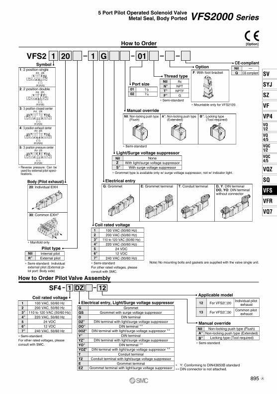
VFS2Symbol
1: 2 position single
2: 2 position double
3: 3 position closed center
4: 3 position exhaust center
5: 3 position pressure center
Electrical entryT: Conduit terminal D, Y: DIN terminal
DO, YO: DIN terminal without connector
F: With foot bracket
G: Grommet E: Grommet terminalBody (Pilot exhaust)20: Individual EXH
30: Common EXH∗
Manual override
Light/Surge voltage suppressor
RcNPT
NPTFG
0102
∗ Semi-standardFor other rated voltages, please consult with SMC.
Thread type
Port size
Option
1 20 011 G
Coil rated voltage
Internal pilotNilExternal pilotR∗
Pilot type
Coil rated voltageApplicable model
SF4 DZ1 12
How to Order Pilot Valve Assembly
123∗4∗56∗7∗
100 VAC, 50/60 Hz200 VAC, 50/60 Hz
110 to 120 VAC (50/60 Hz)220 VAC, 50/60 Hz
24 VDC12 VDC
240 VAC, 50/60 Hz∗ Semi-standardFor other rated voltages, please consult with SMC. ∗ Semi-standard
Nil
B∗A∗
Non-locking push type (Flush)
Individual pilot exhaust
Common pilot exhaust
Non-locking push type (Extended)Locking type (Tool required)
For VFS220
For VFS230
Manual override
12
13
Electrical entry, Light/Surge voltage suppressorGGSDDZ∗DO∗DOZ∗Y∗YZ∗YO∗YOZ∗
TTZ
GrommetGrommet with surge voltage suppressor
DIN terminalDIN terminal with light/surge voltage suppressor
DIN terminal ∗∗DIN terminal with light/surge voltage suppressor ∗∗
DIN terminalDIN terminal with light/surge voltage suppressor
DIN terminal ∗∗DIN terminal with light/surge voltage suppressor ∗∗
Conduit terminalConduit terminal with light/surge voltage suppressor
Grommet terminalGrommet terminal with light/surge voltage suppressor
EEZ
Nil: Non-locking push type(Flush)
A∗: Non-locking push type(Extended)
B∗: Locking type(Tool required)
∗ Semi-standard
∗ Grommet type is available only w/ surge voltage suppressor, not w/ indicator light.
NilZ
NoneWith light/surge voltage suppressor
S∗ With surge voltage suppressor
NilN∗T∗F∗
1 81 4
∗ Semi-standard
∗ Reverse pressure: Can be used by external pilot speci-fications.
∗ Manifold only
∗ Mountable only for VFS2120.
3∗21
4∗
6∗5
7∗
100 VAC (50/60 Hz)200 VAC (50/60 Hz)
110 to 120 VAC (50/60 Hz)220 VAC (50/60 Hz)
24 VDC12 VDC
240 VAC (50/60 Hz)
∗ Semi-standard: Individual external pilot (External pi-lot port: Body side)
∗ Y: Conforming to DIN43650B standard∗∗ DIN connector is not attached.
How to Order
Q
CE-compliantNil —
CE-compliant
[Option]
895
VFS2000 Series5 Port Pilot Operated Solenoid Valve
Metal Seal, Body Ported
SV
SYJ
SZ
VF
VP4VQ1/2
VQ4/5
VQC1/2
VQC4/5
VQZ
SQ
VFS
VFR
VQ7
VFS
A

(A)4 2(B)
3(R2)
1(P)
5(R1)
3(R2)
5(R1)
1(P)
2(B)(A)4
(A)4 2(B)
3(R2)
1(P)
5(R1)
(A)4 2(B)
3(R2)
1(P)
5(R1)
5(R1)
3(R2)
1(P)
(A)4 2(B)
Cylinder Speed Chart
Construction
2 position single 2 position double
3 position closed center/exhaust center/pressure center
Series
VFS2120-02
800700600500400300200100 0
Bore size
ø6 ø10 ø16 ø20 ø25 ø32 ø40 ø40 ø50 ø63 ø80 ø100
Body Ported
Conditions
No.
23
1Description
Stainless steelResin
MaterialAluminum die-casted
Note
4 Resin
——
—
—56
Stainless steel—
7 —
———
∗ Refer to “How to Order Pilot Valve Assembly” on page 895.
Component Parts
Spool/SleeveBody
End platePistonReturn springPilot valve assembly Detent assembly
Closed center
Exhaust center
Pressure center
Averagespeed(mm/s)
CJ2 seriesPressure 0.5 MPaLoad factor 50%Stroke 60 mm
CM2 seriesPressure 0.5 MPaLoad factor 50%Stroke 300 mm
MB, CA2 series Pressure 0.5 MPaLoad factor 50%Stroke 500 mm
Body ported CJ2 series CM2 series
AN110-01
MB, CA2 seriesT0604 x 1 mAS3001F-06
T1075 x 1 mAS4001F-10
Tube bore x LengthSpeed controllerSilencer
VFS2120-02
∗ It is when the cylinder is extending that is meter-out controlled by speed controller which is directly connected with cylinder, and its needle valve with being fully open.
∗ The average velocity of the cylinder is the value that the stroke is divided by the total stroke time.
∗ Load factor: ((Load mass x 9.8)/Theoretical force) x 100%
Use as a guide for selection.Please confirm the actual conditions with SMC Sizing Program.
Perpendicular,upward actuationHorizontalactuation
896
VFS2000 Series

Y(Z) type
GMN209CAXT623-6-7-13
D(Z) type
B1B09-2A6CAXT623-6-7-12
ConnectorGasket
DIN Connector/Gasket Part No.
Gasket
Connector
Grommet terminal: VFS2120-E/EZ
Conduit terminal: VFS2120-T/TZ
DIN terminal: VFS2120-D/DZ/Y/YZ
( ): Y, YZ
Foot bracket (F)Part no.: VFN200-17A
2 Position Single — Grommet, Grommet terminal, Conduit terminal, DIN terminal
Grommet: VFS2120-G
Manual override(Non-locking)
2 x ø3.5 mounting hole
2 x ø3.5 mounting hole
2 x ø3.5 mounting hole
2 x ø3.5 mounting hole
2 x ø3.5 mounting hole
M5: External pilot port∗ Only for external pilot model.
≈ 30
0(L
ead
wire
leng
th)
2 x ø4.5 mounting hole Solenoid valve
With light/surge voltage suppressor (EZ)
Lead wire O.D.Max. ø3.5
Light
Light
With light/surge voltage suppressor (DZ)
With light/surge voltage suppressor (TZ)
Light
( )
Applicable heavy-duty code O.D. ø6 to ø8
Applicable heavy-duty code O.D. ø6 to ø8 (Y: ø4.7 to ø7)
3 x Rc 1/8, 1/4
2 x Rc 1/8
Description
897
VFS2000 Series5 Port Pilot Operated Solenoid Valve
Metal Seal, Body Ported
SV
SYJ
SZ
VF
VP4VQ1/2
VQ4/5
VQC1/2
VQC4/5
VQZ
SQ
VFS
VFR
VQ7
VFS

Conduit terminal: VFS2220-T/TZ VFS2320-T/TZ VFS2420-T/TZ VFS2520-T/TZ
Y(Z) type
GMN209CAXT623-6-7-13
D(Z) type
B1B09-2A6CAXT623-6-7-12
ConnectorGasket
DIN Connector/Gasket Part No.
Gasket
Connector
( ): Y, YZ
2 Position Double, 3 Position — Grommet, Grommet terminal, Conduit terminal, DIN terminal
Grommet terminal: VFS2220-E/EZ VFS2320-E/EZ VFS2420-E/EZ VFS2520-E/EZ
DIN terminal: VFS2220-D/DZ/Y/YZ VFS2320-D/DZ/Y/YZ VFS2420-D/DZ/Y/YZ VFS2520-D/DZ/Y/YZ
Grommet: VFS2220-G, VFS2320-G, VFS2420-G, VFS2520-G
182 (3 position: 192.5)
Manual override(Non-locking)2 x ø3.5 mounting hole
2 x ø3.5 mounting hole
2 x ø3.5 mounting hole
2 x ø3.5 mounting hole
2 x ø3.5 mounting hole
≈ 30
0(L
ead
wire
leng
th)
(M5: External pilot port∗ Only for external pilot model.)
Light
With light/surge voltage suppressor (DZ)
219 (3 position: 229)Light
Light
3 x Rc 1/8, 1/4
Lead wire O.D. Max. ø3.5
With light/surge voltage suppressor (TZ)219 (3 position: 229)
With light/surge voltage suppressor (EZ)182 (3 position: 193)
2 x Rc 1/8
Applicable heavy-duty code O.D. ø6 to ø8
Applicable heavy-duty code O.D. ø6 to ø8 (Y: ø4.7 to ø7)
Description
898
VFS2000 Series
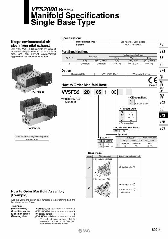
Specifications
Port Specifications
Option
How to Order Manifold Base
VV5FS2-20
VV5FS2-30
Blanking plate VVFS2000-10A-1 With gasket, screw
10520 03VFS2000 Series
Manifold
Symbol
1
Passage Porting specifications2(B), 4(A)3(R2), 5(R1)1(P)
Stations
Base model
VV5FS2
Model Applicable valve model
20
30
Pilot exhaust
Pilot individual EXH
Pilot common EXH
2 stations
15 stations
02
15
RcNPT
NPTFG
∗ Semi-standard
Thread type
P, EA, EB port size
Part no. for mounting bolt and gasketBG-VFS2030
How to Order Manifold Assembly[Example]
03 3 8
Keeps environmental air clean from pilot exhaustUse of the VV5FS2-30 manifold can exhaust intensively the pilot exhaust gas to the base side, and can prevent environmental aggravation due to noise and oil mist.
Manifold base typeStations Max. 15 stations
Bar manifold, Body ported
PassageSymbol Valve2(B), 4(A)
Base3(R2), 5(R1)
Base1(P)
Side: 5(R1), 3(R2)
Common1(P)
Common1
Porting specifications
3 8 Side: 3 8Top: 1 8, 1 4
Top
VFS220--01 02
1 8, 1 4
VFS230--01 02
∗VFS220--01 02
mountable
NilN∗T∗F∗
<Example>(Manifold base)(2 position single)(2 position double)(Blanking plate)
1321
VV5FS2-20-061-03VFS2120-1D-02VFS2220-1D-02VVFS2000-10A-1
•••
••
•
Add the valve and option part numbers in order starting from the first station on the D side.
Common3 8
Common3 8
∗∗∗
The asterisk denotes the symbol for assembly. Prefix it to the part numbers of the solenoid valve.
Q
CE-compliantNil —
CE-compliant
[Option]
899
VFS2000 SeriesManifold Specifications Single Base Type
SV
SYJ
SZ
VF
VP4VQ1/2
VQ4/5
VQC1/2
VQC4/5
VQZ
SQ
VFS
VFR
VQ7
VFS
A

Grommet terminal: E/EZ Conduit terminal: T/TZ DIN terminal: D/DZ/Y/YZ
( ): Y, YZ
Formula for manifold weight M = 0.108n + 0.068 (kg) n: Station
25868
LL1
L2
38393
4108118
5133143
6158168
7183193
8208218
9233243
10258268
FormulaL1 = 25 x n + 8L2 = 25 x n + 18
Stationsn: Station
Type 20 Manifold — Pilot individual exhaust: VV5FS2-20- 1-03
Grommet: G
U side D side
2n x Rc 1/8, 1/4
M3 x 44
4 x ø5 mounting hole
Blanking plate
Pilot EXH
Gasket
Lead wire O.D.Max. ø3.5
Applicable heavy-duty codeO.D. ø6 to ø8
6 x Rc 3/8
Applicable heavy-duty codeO.D. ø6 to ø8 (Y: ø4.7 to ø7)
6 x Rc 3/8
3 po
sitio
n (1
93)
Dou
ble
(182
)
Sin
gle
(125
)
(With light/surge voltage suppressor: 91.5)
(With light/surge voltage suppressor: 101)
3 po
sitio
n (2
29)
Dou
ble
(219
)
Sin
gle
(143
)
(With light/surge voltage suppressor: 96)
(With light/surge voltage suppressor: 106)
3 po
sitio
n (2
29)
Dou
ble
(219
)
Sin
gle
(143
.5)
(With light/surge voltage suppressor: 108.5 (110.5))
(With light/surge voltage suppressor: 117.5 (119.5))
Stations
≈ 300(Lead wire length)
6 x Rc 3/8
6 x Rc 3/8
Station
900
VFS2000 Series

Grommet terminal: E/EZ Conduit terminal: T/TZ DIN terminal: D/DZ/Y/YZ
( ): Y, YZ
Formula for manifold weight M = 0.12n + 0.21 (kg) n: Station
Grommet: G
Type 30 Manifold — Pilot common exhaust: VV5FS2-30- 1-03Station
26292
LL1
L2
387
117
4112142
5137167
6162192
7187217
8212242
9237267
10262292
FormulaL1 = 25 x n + 12L2 = 25 x n + 42
Stations
n: Station
U side D side
2n x Rc 1/8, 1/4
M3 x 44
4 x ø5 mounting hole
Blanking plate
Gasket
3 po
sitio
n (1
93)
Dou
ble
(182
)
Sin
gle
(125
)
3 po
sitio
n (2
29)
Dou
ble
(219
)
Sin
gle
(143
)
Stations
Lead wire O.D.Max. ø3.5
Applicable heavy-duty codeO.D. ø6 to ø8
(With light/surge voltage suppressor: 102.5)
(With light/surge voltage suppressor: 112.5)
3 po
sitio
n (2
29)
Dou
ble
(219
)
Sin
gle
(143
.5)
Applicable heavy-duty codeO.D. ø6 to ø8(Y: ø4.7 to ø7)
(With light/surge voltage suppressor: 115 (117))
(With light/surge voltage suppressor: 124 (126))
(With light/surge voltage suppressor: 98)
(With light/surge voltage suppressor: 107.5)
6 x Rc 3/8
4 x M5 (Pilot EXH port)
≈ 300(Lead wire length)
901
VFS2000 Series5 Port Pilot Operated Solenoid Valve
Metal Seal, Body Ported
SV
SYJ
SZ
VF
VP4VQ1/2
VQ4/5
VQC1/2
VQC4/5
VQZ
SQ
VFS
VFR
VQ7
VFS

(A)4 2(B)
3(R2)
1(P)
5(R1)
3(R2)
5(R1)
1(P)
2(B)(A)4
(A)4 2(B)
3(R2)
1(P)
5(R1)
(A)4 2(B)
3(R2)
1(P)
5(R1)
5(R1)
3(R2)
1(P)
(A)4 2(B)
Model
Standard Specifications
Option Specifications
Manifold
Symbol
VFS3320-E-03
VFS3220-T-03
VFS3120-E-03-F
VFS3120-G-03
VFS3120
VFS3220
VFS3320
VFS3420
VFS3520
VFS31305.06.15.06.15.05.74.95.84.96.5
0.200.140.200.140.200.200.240.150.230.15
1.11.41.11.41.11.41.11.41.11.6
6.87.36.87.36.36.86.57.06.67.0
0.300.230.30.230.270.210.280.220.280.23
1.71.81.71.81.61.71.61.71.61.7
VFS3230
VFS3330
VFS3430
VFS3530
1 43 81 43 81 43 81 43 81 43 8
1200
1500
600
600
600
0.33
0.43
0.45
0.45
0.45
20 or less
15 or less
40 or less
40 or less
40 or less
C[dm3/(s·bar)] b Cv
C[dm3/(s·bar)] b Cv
1 4/2(P A/B) 4/2 5/3(A/B R1/R2)Flow rate characteristics
2 position 3 positionSingle Closed center
Double Exhaust center
Pressure center
Body type Applicable manifold base
Stacking manifoldVFS330VFS320
Common EXH (Manifold base side)Individual EXH (Valve side)
Pilot EXH
Compact yet provides a large flow capacity3/8: C: 6.8 dm3/(s·bar)Low power consumption: 1.8 W DC
Type of actuation
Single
Double
Closedcenter
Pressure center
Exhaust center
PortsizeRc
Note 1) Based on JIS B 8419: 2010 (once per 30 days) for the minimum operating frequency.Note 2) Based on JIS B 8419-2010. (The value at supply pressure 0.5 MPa, ambient/fluid temperature (≈ 20°C))
However, this excludes when in an adhered state. (Be aware that after long periods of holding time, there may be delays in the initial response time.)Note 3) In the case of grommet type.Note 4) Factors of “Note1)” and “Note 2)” are achieved in controlled clean air.
Fluid AirMaximum operating pressureMinimun operating pressure
1.0 MPa0.1 MPa
–10 to 60°C (1)
Non-lube (2)
Non-locking push type (Flush)150/50 m/s2 (3)
100, 200 VAC, 50/60 Hz; 24 VDC–15 to +10% of rated voltage
5.6 VA/50 Hz, 5.0 VA/60 Hz3.4 VA (2.1 W)/50 Hz, 2.3 VA (1.5 W)/60 Hz
InrushHolding
Grommet, Grommet terminal,Conduit terminal, DIN terminal
Ambient and fluid temperature1.5 MPaProof pressure
LubricationPilot valve manual overrideImpact/Vibration resistance EnclosureCoil rated voltageAllowable voltage fluctuation
Class B or equivalent (130°C) (5)Coil insulation typeApparent power(Power consumption)
Electrical entry
Power consumption
Note 1) Use dry air at low temperatures.Note 2) Use turbine oil Class 1 (ISO VG32), if lubricated.Note 3) Impact resistance: No malfunction occurred when it is tested with a drop tester in the axial direction
and at the right angles to the main valve and armature in both energized and de-energized states every once for each condition. (Values at the initial period)
Vibration resistance: No malfunction occurred in a one-sweep test between 45 and 2000 Hz. Test was performed at both energized and de-energized states in the axial direction and at the right angles to the main valve and armature. (Values at the initial period)
Note 4) Based on JIS C 0920. Note 5) Based on JIS C 4003.
Val
ve s
pec
ific
atio
ns
Elec
tric
ity s
peci
ficat
ions
AC
Pilot valve manual override
Coil rated voltage
Foot bracket (With screw)
110 to 120, 220, 240 VAC (50/60 Hz)Non-locking push type (Extended), Locking type (Tool reguired)
Pilot type External pilot (1)
12, 100 VDC
Note 1) Operating pressure: 0 to 1.0 MPaPilot pressure: 0.1 to 1.0 MPa
Note 2) Grommet type is available only w/ surge voltage suppressor (which is directly con-nected with lead wire), not w/ indicator light.
Option With light/surge voltage suppressor (2)
Part no.: VFS3000-52A, VFS3120 (single) only
2 po
sitio
n3
posit
ion
Max. operating
cycle(cpm)
Responsetime(ms)
(Details → P. 913)
Weight(kg)
(1)(2)
(3)
Dustproof (Equivalent to IP50) (4)
1.8 W (2.04 W: With light/surge voltage suppressor)
Model
[Option]
902
5 Port Pilot Operated Solenoid ValveMetal Seal, Body Ported
VFS3000 Series
A

5(R1)
3(R2)
1(P)
(A)4 2(B)
(A)4 2(B)
3(R2)
1(P)
5(R1)
(A)4 2(B)
3(R2)
1(P)
5(R1)
(A)4 2(B)
3(R2)
1(P)
5(R1)
3(R2)
5(R1)
1(P)
2(B)(A)4
Note) No mounting bolts and gaskets are supplied with the valve single unit.
How to Order Pilot Valve Assembly
Symbol1: 2 position single
2: position double
3: position closed center
4: position exhaust center
5: position pressure center
F: With foot bracket
Body (Pilot exhaust)20: Individual EXH
30∗: Common EXH
Manual override Nil: Non-locking push type
(Flush)A∗: Non-locking push type
(Extended) B∗: Locking type
(Tool required)
∗ Semi-standard
Light/Surge voltage suppressor
RcNPT
NPTFG
∗ Semi-standard
∗ Semi-standardFor other rated voltages, please consult with SMC.
∗ Manifold only
Thread type
Option
VFS3 1 20 021 G
Coil rated voltage
Internal pilotNilExternal pilotR∗
Pilot type
Electrical entryT: Conduit terminal D, Y: DIN terminal
DO, YO: DIN terminal without connector
G: Grommet E: Grommet terminal
0203
Port size
∗ Semi-standard
Coil rated voltage Manual overrideApplicable model
SF4 DZ1 21
14
15
16
17
18
19
How to Order
123∗4∗56∗7∗
100 VAC, 50/60 Hz200 VAC, 50/60 Hz
110 to 120 VAC (50/60 Hz)220 VAC, 50/60 Hz
24 VDC12 VDC
240 VAC, 50/60 Hz∗ Semi-standardFor other rated voltages, please consult with SMC.
Nil
B∗
A∗
Non-locking pushtype (Flush)
Non-locking pushtype (Extended)Locking type
(Tool required)
Electrical entry, Light/Surge voltage suppressorGrommet
Grommet with surge voltage suppressorDIN terminal
DIN terminal with light/surge voltage suppressorDIN terminal ∗∗
DIN terminal with light/surge voltage suppressor ∗∗DIN terminal
DIN terminal with light/surge voltage suppressorDIN terminal ∗∗
DIN terminal with light/surge voltage suppressor ∗∗Conduit terminal
Conduit terminal with light/surge voltage suppressorGrommet terminal
Grommet terminal with light/surge voltage suppressor
GGSDDZ∗DO∗DOZ∗Y∗
YZ∗
YO∗
YOZ∗TTZEEZ
Individualpilot
exhaust
Commonpilot
exhaust
A side pilot operator for VFS3 20
B side pilot operator for VFS3220
12345
B side pilot operator for VFS3 20345
A side pilot operator for VFS3 30
B side pilot operator for VFS3230
12345
B side pilot operator for VFS3 30345
∗ Grommet type is available only w/ surge voltage suppressor, not w/ indicator light.
NilZ
NoneWith light/surge voltage suppressor
S∗ With surge voltage suppressor
NilN∗T∗F∗
(External pilot port: Body side. For 30 type, common external pilot (on manifold side).)
∗ Reverse pressure: Can be used by external pilot specifications.
∗ Semi-standard:It will be an individual external pilot.
∗ Mountable only for VFS3120.
Q
CE-compliantNil —
CE-compliant
3∗21
4∗
6∗5
7∗
100 VAC (50/60 Hz)200 VAC (50/60 Hz)
110 to 120 VAC (50/60 Hz)220 VAC (50/60 Hz)
24 VDC12 VDC
240 VAC (50/60 Hz)
1 43 8
∗ Y: Conforming to DIN43650B standard∗∗ DIN connector is not attached.
[Option]
903
VFS3000 Series5 Port Pilot Operated Solenoid Valve
Metal Seal, Body Ported
SV
SYJ
SZ
VF
VP4VQ1/2
VQ4/5
VQC1/2
VQC4/5
VQZ
SQ
VFS
VFR
VQ7
VFS
A

Series
VFS3120-03
Averagespeed(mm/s)
800900
700600500400300200100 0
Bore size
ø6 ø10 ø16 ø20 ø25 ø32 ø40 ø40 ø50 ø63 ø80 ø100 ø125 ø140 ø160
Body Ported
Body ported CJ2 series CM2 series
AN20-02
MB, CA2 series CS1/CS2 series
AN202-02
T0604 x 1 mAS3001F-06
T1075 x 1 mAS4001F-10
T1209 x 1 mAS4001F-12
Tube bore x LengthSpeed controllerSilencer
VFS3120-03
Conditions
Cylinder Speed Chart
CJ2 seriesPressure 0.5 MPaLoad factor 50%Stroke 60 mm
CM2 seriesPressure 0.5 MPaLoad factor 50%Stroke 300 mm
MB, CA2 seriesPressure 0.5 MPaLoad factor 50%Stroke 500 mm
CS1/CS2 seriesPressure 0.5 MPaLoad factor 50%Cylinder stroke 1000 mm
Use as a guide for selection.Please confirm the actual conditions with SMC Sizing Program.
∗ It is when the cylinder is extending that is meter-out controlled by speed controller which is directly connected with cylinder, and its needle valve with being fully open. ∗ The average velocity of the cylinder is the value that the stroke is divided by the total stroke time.∗ Load factor: ((Load mass x 9.8)/Theoretical force) x 100%
Perpendicular,upward actuationHorizontalactuation
904
VFS3000 Series

(A)4 2(B)
3(R2)
1(P)
5(R1)
3(R2)
5(R1)
1(P)
2(B)(A)4
(A)4 2(B)
3(R2)
1(P)
5(R1)
(A)4 2(B)
3(R2)
1(P)
5(R1)
5(R1)
3(R2)
1(P)
(A)4 2(B)
Construction
2 position single 2 position double
No.
23
1Description Material Note
4
—
—56 —7 —
———
∗ Refer to “How to Order Pilot Valve Assembly” on page 903.
Component Parts
3 position closed center/exhaust center/pressure centerClosed center
Exhaust center
Pressure center
Stainless steelReturn springPilot valve assembly Detent assembly
Stainless steelResin
Aluminum die-castedSpool/SleeveBody
End plateResinPiston
—
—
905
VFS3000 Series5 Port Pilot Operated Solenoid Valve
Metal Seal, Body Ported
SV
SYJ
SZ
VF
VP4VQ1/2
VQ4/5
VQC1/2
VQC4/5
VQZ
SQ
VFS
VFR
VQ7
VFS

Y(Z) type
GMN209CAXT623-6-7-13
D(Z) type
B1B09-2A6CAXT623-6-7-12
ConnectorGasket
DIN Connector/Gasket Part No.
Gasket
Connector
Grommet terminal: VFS3120-E/EZ
Conduit terminal: VFS3120-T/TZ
DIN terminal: VFS3120-D/DZ/Y/YZ
( ): Y, YZ
Foot bracket (F)Part no.: VFS3000-52A
2 Position Single — Grommet, Grommet terminal, Conduit terminal, DIN terminal
Grommet: VFS3120-G
Manual override(Non-locking)2 x ø4.3 mounting hole M5: External pilot port
(For external pilot model)
2 x ø6 mounting hole
Solenoid valve
≈ 30
0
(L
ead
wire
leng
th)
2 x ø4.3 mounting hole
2 x ø4.3 mounting hole
2 x ø4.3 mounting hole
2 x ø4.3 mounting hole
Lead wire O.D.Max. ø3.5
With light/surge voltage suppressor (EZ)
Applicable heavy-duty cordO.D. ø6 to ø8(Y: ø4.7 to ø7)
Light
Light
Light
With light/surge voltage suppressor (DZ)
With light/surge voltage suppressor (TZ)Applicableheavy-duty cordO.D. ø6 to ø8
Description
906
VFS3000 Series

Y(Z) type
GMN209CAXT623-6-7-13
D(Z) type
B1B09-2A6CAXT623-6-7-12
ConnectorGasket
DIN Connector/Gasket Part No.
Gasket
Connector
Grommet terminal: VFS3220-E/EZ VFS3320-E/EZ VFS3420-E/EZ VFS3520-E/EZ
Conduit terminal: VFS3220-T/TZ VFS3320-T/TZ VFS3420-T/TZ VFS3520-T/TZ
( ): Y, YZ
2 Position Double, 3 Position — Grommet, Grommet terminal, Conduit terminal, DIN terminal
Grommet: VFS3220-G, VFS3320-G, VFS3420-G, VFS3520-G
DIN terminal: VFS3220-D/DZ/Y/YZ VFS3320-D/DZ/Y/YZ VFS3420-D/DZ/Y/YZ VFS3520-D/DZ/Y/YZ
Manual override(Non-locking)2 x ø4.3 mounting hole
2 x ø4.3 mounting hole
Applicable heavy-duty cordO.D. ø6 to ø8
231 (3 position: 241)
231 (3 position: 241)
With light/surge voltage suppressor (TZ)
2 x ø4.3 mounting hole
M5: External pilot port(For external pilot model)
Lead wire O.D.Max. ø3.5
194 (3 position: 204)
194 (3 position: 204)
With light/surge voltage suppressor (EZ)
Light
2 x ø4.3 mounting hole
Light
2 x ø4.3 mounting hole
Light
Applicable heavy-duty cordO.D. ø6 to ø8 (Y: ø4.7 to ø7)
With light/surge voltage suppressor (DZ)
≈ 30
0(L
ead
wire
leng
th)
Description
907
VFS3000 Series5 Port Pilot Operated Solenoid Valve
Metal Seal, Body Ported
SV
SYJ
SZ
VF
VP4VQ1/2
VQ4/5
VQC1/2
VQC4/5
VQZ
SQ
VFS
VFR
VQ7
VFS

[Option]
Specifications
Port Specifications
Option
How to Order Manifold BaseVV5FS3-31
Manifold base typeStations Max. 15 stations
Stacking type
PassageSymbol Valve BaseBase
Porting specifications
Blanking plateSUP block plateEXH block plate
105 03VFS3000 Series
Manifold
Symbol
1
Passage Porting specifications3(R2), 5(R1) 1(P)
Stations
Base model
VV5FS3 31
Model Applicable valve model
31
Pilot exhaustPilot common EXH
02
15
RcNPT
NPTFG
∗ Semi-standard
Thread type
P, EA, EB port size
2(B), 4(A)
Part no. for mounting bolt and gasketBG-VFS3030
03 3 8
Keeps environmental air clean from pilot exhaustUse of the VV5FS3-31 manifold can exhaust intensively the pilot exhaust gas to the base side, and can prevent environmental aggravation due to noise and oil mist. 2(B), 4(A) 3(R2), 5(R1)1(P)
Side: ( ) Top: ( )3(R2), 5(R1)
Common1(P)
Common1 3 8 ,14 3 8 Side: ( )3 8
With gasket, screwAXT636-10A
VVFS3000-10A-1—
AXT636-11A —
Note) Individual SUP or EXH is possible with bottom porting of SUP or EXH. For your order, please indicate it in the manifold specification sheet.
Top
VFS330--
2 stations
15 stations 1 4, 3 8
NilN∗T∗F∗
0203
VFS320-- 0203
Note) Also VFS320 is possible to manifold. In this case, it uses an indi-vidual pilot exhaust.
•••
••
• Common3 8
Common3 8
Type 30Type 20
How to Order Manifold Assembly [Example]
<Example>(Manifold base)(2 position single)(2 position double)(Blanking plate)
1321
VV5FS3-31-061-03VFS3130-1D-02VFS3230-1D-02VVFS3000-10A-1
Add the valve and option part numbers in order starting from the first station on the D side.
∗∗∗
The asterisk denotes the symbol for assem-bly. Prefix it to the part numbers of the sole-noid valve.
Q
CE-compliantNil —
CE-compliant
908
VFS3000 SeriesManifold SpecificationsStacking Type
A

PE
5
3
EA
EB
PE
P
1
Replacement Parts
Replacement Parts: Sub Assembly
No.123456789
10111213
DescriptionGasketGasketO-ringO-ringO-ringO-ringHexagon socket head cap screwHexagon socket head cap screwSpring washerHexagon socket head taper plugHexagon socket head taper plugTie-rodTension bolt A
MaterialNBR
HNBRNBRNBRNBRNBR
Carbon steelCarbon steelCarbon steelCarbon steelCarbon steelCarbon steelCarbon steel
Part no.VVFS3000-31
VVFS3000-9-1HKA00175KA00358KA00291KA00336
AXT335-37-1#1CA00746EC00022TB00094TB00155
VVFS3000-53- VVFS3000-50-1Note)
No. Description Assembly part no.
14
15
16
VVFS3000-1A-30
VVFS3000-2A-30
VVFS3000-3A-30
End plate (U) !5, O-ring e, r, t, y, Hexagon socket head cap screw i, Spring washer o, Hexagon socket head taper plug !0, !1
End plate (U) !6, Hexagon socket head cap screw u, Spring washer o
Note) For increasing the manifold bases (included in the manifold block assembly)
!5
!1o
i
ry
t
!2
e!0
!3
w
!4
q u
!6
For increasing the manifold bases, please order the manifold block assembly number of the replacement parts assembly !4.(As the manifold block assembly includes the tension bolt A !3, it is not necessary to additionally order the tie-rod !2.)
Manifold Base Construction — Body ported type
U side
D side
Stations
Manifold block assemblyEnd plate assembly (U side)End plateassembly (D side)
Manifold block !4, Gasket q, w, Hexagon socket head cap screw u, Tension bolt A !3.
Component parts
909
VFS3000 Series5 Port Pilot Operated Solenoid Valve
Metal Seal, Body Ported
SV
SYJ
SZ
VF
VP4VQ1/2
VQ4/5
VQC1/2
VQC4/5
VQZ
SQ
VFS
VFR
VQ7
VFS
A
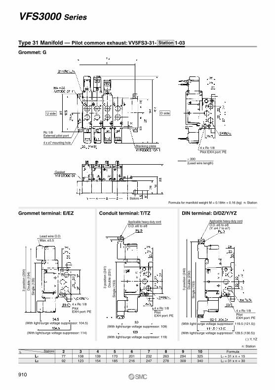
Grommet terminal: E/EZ Conduit terminal: T/TZ DIN terminal: D/DZ/Y/YZ
( ): Y, YZ
Formula for manifold weight M = 0.184n + 0.16 (kg) n: Station
Grommet: G
Type 31 Manifold — Pilot common exhaust: VV5FS3-31- 1-03
27792
LL1
L2
3108123
4139154
5170185
6201216
7232247
8263278
9294309
10325340
FormulaL1 = 31 x n + 15L2 = 31 x n + 30
Stations
n: Station
Rc 1/8External pilot port
4 x ø7 mounting holeBlanking plate
Gasket
Stations
Lead wire O.D.Max. ø3.5
Applicable heavy-duty cordO.D. ø6 to ø8
4 x Rc 1/8PilotEXH port: PE
4 x Rc 1/8PilotEXH port: PE
4 x Rc 1/8PilotEXH port: PE
(With light/surge voltage suppressor: 104.5)
(With light/surge voltage suppressor: 114)
(With light/surge voltage suppressor: 109)
(With light/surge voltage suppressor: 119)
(With light/surge voltage suppressor: 119.5 (121.5))
(With light/surge voltage suppressor: 128.5 (130.5))
3 po
sitio
n (2
04)
Dou
ble
(194
)S
ingl
e (1
35)
3 po
sitio
n (2
41)
Dou
ble
(231
)S
ingl
e (1
53)
Applicable heavy-duty cordO.D. ø6 to ø8(Y: ø4.7 to ø7)
3 po
sitio
n (2
40)
Dou
ble
(230
)S
ingl
e (1
53)
4 x Rc 1/8Pilot EXH port: PE
U side D side
≈ 300(Lead wire length)
Station
910
VFS3000 Series

911
SV
SYJ
SZ
VF
VP4VQ1/2
VQ4/5
VQC1/2
VQC4/5
VQZ
SQ
VFS
VFR
VQ7
VFS

VFS2
Symbol1: 2 position single
2: 2 position double
3: 3 position closed center
4: 3 position exhaust center
5: 3 position pressure center
Electrical entryD: DIN terminal
F: With foot bracket
Body (Pilot exhaust)20: Individual EXH
30: Common EXH∗
Manual overrideNil: Non-locking push type
(Flush)A∗: Non-locking push type
(Extended)B∗: Locking type
(Tool required)
∗ Semi-standard
NilZ
NoneWith light/surge voltage suppressor
Light/Surge voltage suppressor
NilN∗
RcNPT
NPTFG
T∗F∗
0102
1 81 4
∗ Semi-standard
∗ Semi-standard
∗ Reverse pressure: Can be used by external pilot specifications.
∗ Manifold only
∗ Mountable only for VFS2120.
Thread type
Port size
OptionConforming toCSA standard
1 20 0130 1
Coil rated voltage
3∗21
4∗
6∗5
7∗
100 VAC (50/60 Hz)200 VAC (50/60 Hz)
110 to 120 VAC (50/60 Hz)220 VAC (50/60 Hz)
24 VDC12 VDC
240 VAC (50/60 Hz)Internal pilotNilExternal pilotR∗
Pilot type
Refer to standard products for specifications and dimensions.
How to Order
∗ Semi-standard: Individual external pilot (External pilot port: Body side)
D
(A)4 2(B)
3(R2)
1(P)
5(R1)
(A)4 2(B)
3(R2)
1(P)
5(R1)
(A)4 2(B)
3(R2)
1(P)
5(R1)
3(R2)
5(R1)
1(P)
2(B)(A)4
5(R1)
3(R2)
1(P)
(A)4 2(B)
912
5 Port Pilot Operated Solenoid ValveMetal Seal, Body Ported
VFS2000 Series
A

(A)4 2(B)
3(R2)
1(P)
5(R1)
(A)4 2(B)
3(R2)
1(P)
5(R1)
(A)4 2(B)
3(R2)
1(P)
5(R1)
3(R2)
5(R1)
1(P)
2(B)(A)4
5(R1)
3(R2)
1(P)
(A)4 2(B)
Symbol1: 2 position single
2: 2 position double
3: 3 position closed center
4: 3 position exhaust center
5: 3 position pressure center
F: With foot bracket
Body (Pilot exhaust)20: Individual EXH
30: Common EXH∗
Manual overrideNil: Non-locking push type
(Flush)A∗: Non-locking push type
(Extended)B∗: Locking type
(Tool required)
∗ Semi-standard
NilZ
NoneWith light/surge voltage suppressor
Light/Surge voltage suppressor
RcNPT
NPTFG
NilN∗T∗F∗
∗ Semi-standard
∗ Reverse pressure: Can be used by external pilot specifications.
∗ Manifold only
∗ Mountable only for VFS3120.
Thread typeOption
VFS3 1 20 021
Coil rated voltage
Internal pilotNilExternal pilotR∗
Pilot type
∗ Semi-standard: Individual external pilot (External pilot port: Body side. For 30 type, common external pilot (on manifold side).)
Electrical entryD: DIN terminal
02 1 403 3 8
Port size
Conforming toCSA standard
30
Refer to standard products for specifications and dimensions.
How to Order
∗ Semi-standard
3∗21
4∗
6∗5
7∗
100 VAC (50/60 Hz)200 VAC (50/60 Hz)
110 to 120 VAC (50/60 Hz)220 VAC (50/60 Hz)
24 VDC12 VDC
240 VAC (50/60 Hz)
D
913
5 Port Pilot Operated Solenoid ValveMetal Seal, Body Ported
VFS3000 SeriesSV
SYJ
SZ
VF
VP4VQ1/2
VQ4/5
VQC1/2
VQC4/5
VQZ
SQ
VFS
VFR
VQ7
VFS
A

(A)4 2(B)
3(R2)
1(P)
5(R1)
3(R2)
5(R1)
1(P)
2(B)(A)4
(A)4 2(B)
3(R2)
1(P)
5(R1)
(A)4 2(B)
3(R2)
1(P)
5(R1)
(A)4 2(B)
3(R2)
1(P)
5(R1)
5(R1)
3(R2)
1(P)
(A)4 2(B)
Model
Symbol
Plug-in type
Non plug-in type
Type of actuation
Model
Plug-in Non plug-in
1200
1200
1 4/2(P A/B) 4/2 5/3(A/B R1/R2)Flow rate characteristics
VFS2300
VFS2400
VFS2500
VFS2310
VFS2410
VFS2100
VFS2200
VFS2110 2.42.52.42.52.32.52.42.52.52.81.21.2
0.160.180.160.180.140.180.150.200.110.17
––
0.550.580.550.580.530.580.540.600.550.63
––
2.82.82.82.82.62.62.72.72.72.71.31.3
0.200.210.200.210.200.230.250.240.200.22
––
0.650.650.650.650.610.620.630.630.620.63
––
VFS2210
VFS2510
VFS2600 VFS2610
1 8
1 8
1 4
1 41 81 41 81 41 81 41 81 4
600
600
600
600
20 or less
20 or less
20 or less
15 or less
13 or less
25 or less
0.43
0.43
0.34
0.42
0.43
0.6
2 position 3 positionSingle Closed center
Double Exhaust center
Pressure center
Double check Sub-plate
Standard typeCompact type
31.025.5
0.20.13
2.22.8
∗ 2 position single Rc 1/4
Compact yet provides a large flow capacity1/4: C: 2.8 dm3/(s·bar)Low power consumption: 1.8 W DCEasy maintenance2 types of sub-plates: Plug-in and non plug-in
Note 1) Based on JIS B 8419: 2010 (Once per 30 days) for the minimum operating frequency.Note 2) Based on JIS B 8419-2010. (The value at supply pressure 0.5 MPa, ambient/fluid temperature (≈ 20°C))
However, this excludes when in an adhered state. (Be aware that after long periods of holding time, there may be delays in the initial response time.)
Note 3) Values for VFS200-FZ-01.Note 4) Factors of “Note 1)” and “Note 2)” are ones achieved
in controlled clean air.
Single
Double
Double check
Closedcenter
Pressure center
Exhaust center
PortsizeRc C
[dm3/(s·bar)] b CvC
[dm3/(s·bar)] b Cv
Standard SpecificationsFluidMaximum operating pressure
Min. operating pressure
InrushHolding
2 position3 position
Grommet terminal, DIN terminalConduit terminal
Ambient and fluid temperatureProof pressure
LubricationPilot valve manual overrideImpact/Vibration resistance
Enclosure
Coil rated voltageAllowable voltage fluctuationCoil insulation typeApparent power(Power consumption)
Electrical entryPlug-in type
Non plug-in type
Power consumption DC
Note 1) Use dry air at low temperatures. Note 2) Use turbine oil Class 1 (ISO VG32), if lubricated.Note 3) Impact resistance: No malfunction occurred when it is tested with a drop tester in the axial direction and at the
right angles to the main valve and armature in both energized and de-energized states every once for each condition. (Values at the initial period)
Vibration resistance: No malfunction occurred in a one-sweep test between 45 and 2000 Hz. Test was performed at both ener-gized and de-energized states in the axial direction and at the right angles to the main valve and armature. (Values at the initial period)
Note 4) Based on JIS C 0920. Note 5) Based on JIS C 4003.Note 6) The F type enclosure described above shows that without the light/surge voltage suppressor. The F
type enclosure with the light/surge voltage suppressor is equivalent to IP50.
Val
ve s
pec
ific
atio
ns
Elec
tric
ity s
peci
ficat
ions
Air1.0 MPa0.1 MPa
0.15 MPa
–10 to 60°C (1)
Non-lube (2)
Non-locking push type (Flush)150/50 m/s2 (3)
Type G, E: Dustproof (Equivalent to IP50), Type F, T, D: Splashproof (Equivalent to IP54) (4) (6)
100, 200 VAC, 50/60 Hz; 24 VDC–15 to +10% of rated voltage
5.6 VA/50 Hz, 5.0 VA /60 Hz3.4 VA (2.1 W)/50 Hz, 2.3 VA (1.5 W)/60 Hz
1.5 MPa
Class B or equivalent (130°C) (5)
1.8 W (2.04 W: With light/surge voltage suppressor)
AC
Option Specifications
Manual override
Coil rated voltage
Option
110 to 120, 220, 240 VAC, 50/60 HzNon-locking push type (Extended), Locking type (Tool required), Locking type (Lever)
Pilot type External pilot Note)
12, 100 VDC
Note) Operating pressure: 0 to 1.0 MPa Pilot pressure 2 position: 0.1 to 1.0 MPa 3 position: 0.15 to 1.0 MPa
Porting specificationsWith light/surge voltage suppressor
Bottom ported
L (mm)
Weight(kg)
Sonic conductance ∗ C [dm3/(s·bar)]
Compact, lightweight type sub-plateCompared with the standard type, this is the sub-plate having the reduced external dimensions and lighter weight. But, use caution that Cv factor or piping port position is different from the standards. For details, refer to page 938.
2 po
sitio
n3
posi
tion
Max. operating
cycle(cpm)
(Details → P. 1004)
Responsetime(ms)
Weight(kg)
(1)(2)
(3)
VFS2000 series is compatible with the old models, VF200 and VF210 series.
914
[Option]
5 Port Pilot Operated Solenoid ValveMetal Seal, Plug-in/Non Plug-in
VFS2000 Series
A

∗ Semi-standard: External pilot can be mounted on only the sub-plate or manifold for the external pilot.
[Option]
(A)4 2(B)
3(R2)
1(P)
5(R1)
3(R2)
5(R1)
1(P)
2(B)(A)4
(A)4 2(B)
3(R2)
1(P)
5(R1)
(A)4 2(B)
3(R2)
1(P)
5(R1)
(A)4 2(B)
3(R2)
1(P)
5(R1)
5(R1)
3(R2)
1(P)
(A)4 2(B)
How to Order Pilot Valve Assembly
2
2
00 01FVFS2 5
1 E10VFS2
Symbol
1
2 position single
2
2 position double
3
3 position closed center
4
3 position exhaust center
5
3 position pressure center
6
3 position double check
O: Plug-in typesub-plate
Body type
OptionNilZ
NoneWith light/surge voltage suppressor
Porting specificationsNilB∗
OptionNilZS∗
Thread type
Port sizeNil
01
Without sub-plate
02
Coil rated voltage
Body type
Pilot type
∗ Semi-standardFor other rated voltages, please consult with SMC.
Electrical entryG: Grommet
1: Non plug-in typesub-plate
E: Grommet terminal T: Conduit terminal D, Y: DIN terminalDO, YO: DIN terminal without connector
∗ Semi-standard
Pilot valve manual override
NilR∗
02
Plug-in
Non plug-in 2
F: Plug-in type
Electrical entry
Port sizeNil
01 Non plug-in type,Standardtype
Without sub-plate
1 8
1 402
Non plug-in type,Compacttype
1 8
1 4Note)
Note)S01
S02
Note)
Note)
P01
P02
123∗4∗56∗7∗
∗ Semi-standardFor other rated voltages, please consult with SMC. ∗ Semi-standard
Coil rated voltage
SF4 DZ1 20Electrical entry, Light/Surge voltage suppressor
GGS
F
DDZDODOZYYZ
YOYOZTTZEEZ
How to Order
Side portedBottom ported
NoneWith light/surge voltage suppressor
With surge voltage suppressor
RcNPT
NPTFG
NilN∗
T∗
F∗
∗ Semi-standard
∗ Semi-standard
Plug-in type conduit terminal(With terminal block)Standard type
1 8
1 4
123∗4∗56∗
100 VAC, 50/60 Hz200 VAC, 50/60 Hz
110 to 120 VAC, 50/60 Hz220 VAC, 50/60 Hz
24 VDC12 VDC
7∗ 240 VAC, 50/60 Hz
Nil: Non-locking push type(Flush)
B∗: Locking type(Tool required)
A∗: Non-locking push type(Extended)
C∗: Locking type(Lever)
Internal pilotExternal pilot
Plug-in type grommet(With attachment plug lead wire)Compact type
1 8
1 4
Note) Please note Cv factor and piping port loca-tion of compact sub-plate is different from standard. Refer to page 938 for details.
Note) Please note Cv factor and piping port location of com-pact sub-plate are different from standard. Refer to page 938 for details.
100 VAC, 50/60 Hz200 VAC, 50/60 Hz110 to 120 VAC (50/60 Hz)
220 VAC, 50/60 Hz24 VDC12 VDC
240 VAC, 50/60 Hz
Nil
B∗
A∗
Non-lockingpush type
(Flush)
Non-lockingpush type(Extended)
Locking type(Tool required)
C∗ Locking type(Lever)
Manualoverride
Grommet
Plug-in Plug-in
Non plug-in
Grommet with surge voltage suppressorDIN terminal
DIN terminal with light/surge voltage suppressorDIN terminal∗
DIN terminal with light/surge voltage suppressor∗
DIN terminalDIN terminal with light/surge voltage suppressor
∗ DIN connector is not attached.∗∗ Refer to page 1009 for voltage conversion.∗∗∗ Y: Conforming to DIN43650B standard
Non plug-in
DIN terminal∗
DIN terminal with light/surge voltage suppressor∗
Conduit terminalConduit terminal with light/surge voltage suppressor
Grommet terminalGrommet terminal with light/surge voltage suppressor
With attachment plug lead wire
With terminal block
∗ Grommet type is available only w/ surge voltage suppressor, not w/ indicator light.
Q
CE-compliantNil —
CE-compliant
∗ Combining double check spacer with external pilot will not work.
∗
915
VFS2000 Series5 Port Pilot Operated Solenoid Valve
Metal Seal, Plug-in/Non Plug-in
SV
SYJ
SZ
VF
VP4VQ1/2
VQ4/5
VQC1/2
VQC4/5
VQZ
SQ
VFS
VFR
VQ7
VFS
A

System Components
System
A
800700600500400300200100 0
B
800700600500400300200100 0
Bore size
ø20 ø25 ø32 ø40 ø40 ø50 ø63 ø80 ø100 ø125 ø140 ø160
A
B
Double Check Spacer/Specifications
Double checkspacer part no.
Applicable valve model
Specifications Check Valve Operating
Caution
Cylinder Speed Chart
Can hold an intermediate cylinder position for an extended timeIf the double check spacer with a built-in double check valve is combined, it will en-able the cylinder to stop in the intermediate stroke and maintain its position for a long time without being affected by the leakage between the spools.
• The combination of VFS21 0, VFS22 0 and a double check spacer can be used as prevention of falling at the stroke end but cannot hold the intermediate position of the cylinder.
VFS2000Series
AN110-01(S = 35 mm2)
AS3000-02(S = 12 mm2)
Tube bore x Length
T0604 x 1 m
T1075 x 1 m
System Solenoid valve Speed controller
Silencer
1 8
VFS2000Series
AN110-01(S = 35 mm2)
AS4000-02(S = 21 mm2)
Plug-in type Non plug-in type
VVFS2000-22A-1 VVFS2000-22A-2
VFS2400-F VFS2410-GETD
Double check spacer
Averagespeed(mm/s)
CM seriesPressure 0.5 MPaLoad factor 50%Stroke 300 mm
MB, CA2 seriesPressure 0.5 MPaLoad factor 50%Stroke 500 mm
CS1/CS2 seriesPressure 0.5 MPaLoad factor 50%Cylinder stroke 1000 mm
Use as a guide for selection.Please confirm the actual conditions with SMC Sizing Program.
∗ It is when the cylinder is extending that is meter-out controlled by speed controller which is directly connected with cylinder, and its needle valve with being fully open.
∗ The average velocity of the cylinder is the value that the stroke is divided by the total stroke time.
∗ Load factor: ((Load mass x 9.8)/Theoretical force) x 100%
Perpendicular,upward actuationHorizontalactuation
Rc
1 4Rc
Cylinder pressure Check valve
Operating range
Cylinder pressure P2 (MPa)
Piston SUP side pressure (P1)• In the case of 3 position double check valve (VFS260), check the leakage from piping and fittings in between valve and cylinder by means of synthetic detergent solutions, and ensure that there is no such leakage found there. Also check the leakage from cylinder seal and piston seal. If there is any leakage, sometimes the cylinder, when valve is de-energized, can move without stopping at intermediate position.
• Be aware that if the exhaust side is restricted excessively, the intermediate stopping accuracy will decrease and will lead to improper intermediate stops.
• Combining double check spacer with external pilot will not work.
01
01
SU
P s
ide
pres
sure
P1
(MP
a)
916
VFS2000 Series

(A)4 2(B)
3(R2)
1(P)
5(R1)
(A)4 2(B)
3(R2)
1(P)
5(R1)
(A)4 2(B)
3(R2)
1(P)
5(R1)
3(R2)
5(R1)
1(P)
2(B)(A)4
5(R1)
3(R2)
1(P)
(A)4 2(B)
Construction
Component Parts Sub-plate Assembly (Standard) Part No.
2 position single 2 position double
No.
23
1Description Material Note
4—
56 —7 —8 —9 —
10 —11 —12 — —13 — —
∗ Refer to “How to Order Pilot Valve Assembly” on page 915.
Plug-in
Non plug-in
Plug-in
Non plug-in
Sub-plate Assembly (For External Pilot) Part No.
∗ Mounting bolt and gasket are not included.
3 position closed center/exhaust center/pressure centerClosed center
Exhaust center
Pressure center
Aluminum die-castedStainless steel
Aluminum die-castedSub-plateBody
Spool/SleeveResinAdapter plate
——
—ResinEnd plate —ResinPistonResinJunction coverResinCover
HNBRStainless steelReturn spring
GasketSteelHexagon socket head cap screw
Detent assemblyPilot valve assembly
VFS2000-LP- (N, T, F)
VFS2000-LS- (N, T, F)
0102
0102
VFS2000-LP-R (N, T, F)
VFS2000-LS-R (N, T, F)
0102
0102
Part no. for mounting bolt and gasket Note
BG-VFS2000-1
BG-VFS2000
Groove gasket type(After October 2012) Note)
Plate gasket type(Earlier than September, 2012) Note)
Note) When ordering the parts shown above for the replacement, note that the described date may slightly vary depending on the product being used.
917
VFS2000 Series5 Port Pilot Operated Solenoid Valve
Metal Seal, Plug-in/Non Plug-in
SV
SYJ
SZ
VF
VP4VQ1/2
VQ4/5
VQC1/2
VQC4/5
VQZ
SQ
VFS
VFR
VQ7
VFS
A

( ): Rc 1 8 ( ): Rc 1 8
( ): Rc 1 8
Plug-in — 2 Position single/Double/3 Position closed center/Exhaust center/Pressure center/Double check
2 position single: VFS2100-F(Z)-01 02
2 position double: VFS2200-F(Z)-01 02
3 position closed center: VFS2300-F(Z)-01 02
3 position exhaust center: VFS2400-F(Z)-01 02
3 position pressure center: VFS2500-F(Z)-01 02
3 position double check: VFS2600-F(Z)-01 02
Manual override(Non-locking)
2 x ø5 mounting hole
Manual override(Non-locking)
2 x ø5 mounting hole
Manual override(Non-locking)
2 x ø5 mounting hole
Electrical entry
With light/surge voltage suppressor
With light/surge voltage suppressor
With light/surge voltage suppressor
1(P), 4(A), 2(B) bottom ported
3(R2), 5(R1) bottom ported
Bottom ported
(External pilot port)
Pilot EXH port
150.5 (3 position: 158)
164.5 (3 position: 171)
3 x Rc , 1 8 1 4
2 x Rc 1 8
918
VFS2000 Series

Gasket
Connector
( ): Y, YZ
Non Plug-in — 2 Position single Grommet: VFS2110-G(S)-01
02
Grommet terminal: VFS2110-E(Z)-01 02
Conduit terminal: VFS2110-T(Z)-01 02
DIN terminal: VFS2110-D Y(Z)-01
02
( ): Rc 1 8
Manual override(Non-locking)
2 x ø5 mounting hole 1(P), 4(A), 2(B) bottom ported
3(R2), 5(R1) bottom ported
Bottom ported
Pilot EXH port M5 x 0.8
Lead wire O.D. Max. ø3.5 With light/surge voltage suppressor
With light/surgevoltage suppressor
Applicable heavy-duty cordO.D. ø6 to ø8
Light
Light
Applicable heavy-duty cordO.D. ø6 to ø8(Y: ø4.7 to ø7)
(External pilot port M5 x 0.8)
≈ 30
0(L
ead
wire
leng
th)
3 x Rc , 1 8 1 4
2 x Rc 1 8
With light/surge voltage suppressor
Light
Y(Z) type
GMN209CAXT623-6-7-13
D(Z) type
B1B09-2A6CAXT623-6-7-12
ConnectorGasket
DIN Connector/Gasket Part No.Description
919
VFS2000 Series5 Port Pilot Operated Solenoid Valve
Metal Seal, Plug-in/Non Plug-in
SV
SYJ
SZ
VF
VP4VQ1/2
VQ4/5
VQC1/2
VQC4/5
VQZ
SQ
VFS
VFR
VQ7
VFS
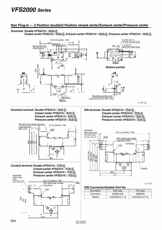
Gasket
Connector
( ): Y, YZ
Non Plug-in — 2 Position double/3 Position closed center/Exhaust center/Pressure center Grommet: Double VFS2210-G(S)-01
02Closed center VFS2310-G(S)-01
02, Exhaust center VFS2410-G(S)-01 02, Pressure center VFS2510-G(S)-01
02
1 8( ): Rc
Grommet terminal: Double VFS2210-E(Z)-01 02
Closed center VFS2310-E(Z)-01 02
Exhaust center VFS2410-E(Z)-01 02
Pressure center VFS2510-E(Z)-01 02
Conduit terminal: Double VFS2210-T(Z)-01 02
Closed center VFS2310-T(Z)-01 02
Exhaust center VFS2410-T(Z)-01 02
Pressure center VFS2510-T(Z)-01 02
DIN terminal: Double VFS2210-D Y(Z)-01
02 Closed center VFS2310-D
Y(Z)-01 02
Exhaust center VFS2410-D Y(Z)-01
02Pressure center VFS2510-D
Y(Z)-01 02
Manual override(Non-locking)
150.5 (3 position: 158)2 x ø5mounting hole
≈ 30
0(L
ead
wire
leng
th)
1(P), 2(B), 4(A) bottom ported
3(R2), 5(R1) bottom ported
Bottom ported
Pilot EXH port M5 x 0.8
With light/surge voltage suppressor
With light/surge voltage suppressor
Lead wire O.D. Max. ø3.5
151 (3 position: 159)
Light
With light/surge voltage suppressor (DZ)
Applicable heavy-duty cord
Light
Applicableheavy-duty cord
187.5 (3 position: 195)
187.5 (3 position: 195)
(External pilot port M5 x 0.8)
3 x Rc , 1 8 1 4
2 x Rc 1 8
O.D. ø6 to ø8(Y: ø4.7 to ø7)
O.D. ø6 to ø8
Light
Y(Z) type
GMN209CAXT623-6-7-13
D(Z) type
B1B09-2A6CAXT623-6-7-12
ConnectorGasket
DIN Connector/Gasket Part No.Description
920
VFS2000 Series

Gasket
Connector
( ): Y, YZ
Non Plug-in — 3 Position double check
Grommet terminal: VFS2610-E(Z)-01 02 DIN terminal: VFS2610-D
Y(Z)-01 02
1 8( ): Rc
Bottom ported
Grommet: VFS2610-G(S)-01 02
Conduit terminal: VFS2610-T(Z)-01 02
Manual override(Non-locking)
2 x ø5 mounting hole
≈ 30
0(L
ead
wire
leng
th)
3 x Rc 1/8, 1/41(P), 2(B), 4(A) bottom ported2 x Rc 1/83(R2), 5(R1) bottom ported
(External pilot port)(M5 x 0.8)
Pilot EXH portM5 x 0.8
Lead wire O.D. Max. ø3.5
Applicableheavy-duty code
With light/surge voltage suppressor
With light/surge voltage suppressor (DZ)
Light
Applicableheavy-duty code
Light
With light/surge voltage suppressor
Light
O.D. ø6 to ø8
O.D. ø6 to ø8(Y: ø4.7 to ø7)
Y(Z) type
GMN209CAXT623-6-7-13
D(Z) type
B1B09-2A6CAXT623-6-7-12
ConnectorGasket
DIN Connector/Gasket Part No.Description
921
VFS2000 Series5 Port Pilot Operated Solenoid Valve
Metal Seal, Plug-in/Non Plug-in
SV
SYJ
SZ
VF
VP4VQ1/2
VQ4/5
VQC1/2
VQC4/5
VQZ
SQ
VFS
VFR
VQ7
VFS

Symbol (Passage)
∗ The external pilot type is not available.
Symbol Passage Portingspecifications A, BEA, EBP
12∗3∗4∗5∗6∗7∗8∗
SideBottom
SideBottom
SideBottom
SideBottom
Common
Individual
Common
Individual
Common
Common
Individual
Individual
VV5FS2 01T
VV5FS2 01C 1
D side mountingU side mounting
DU
Connector mounting direction
CE-compliantNilQ
—CE-compliant
Nil RcNPT
NPTFG
N∗T∗F∗
Thread type
RcNPT
NPTFG
NilN∗T∗F∗
Thread type
1 station
16 stations
01
16
Stations
01VV5FS2
Symbol (Passage)
Symbol Passage Portingspecifications A, BEA,EBP
12∗3∗4∗5∗6∗7∗8∗
SideBottom
SideBottom
SideBottom
SideBottom
Common
Individual
Common
Individual
Common
Common
Individual
Individual
Port sizeSymbol P, EA, EB0102M
CE-compliantNilQ
—CE-compliant
NilR
Internal pilotExternal pilot
Pilot type
Yes
No
Yes
No
Externalpilot
Nil1
Separate junction coverOne-piece junction cover
Junction cover
08
D 05 2 01
1 02
06 1 01
[Option]
VFS2000 SeriesManifold
Plug-in Type: With Terminal BlockSince lead wires of solenoid valve are connect-ed with the terminals on upper surface of termi-nal block, corresponding lead wires from power source can be wired at the bottom of terminal block.
∗ Max. 8 stations
One-piece junction cover
Individual junction cover Conduit port
Plug-in Type: With Attachment Plug Lead WireThe insert plug is attached to the manifold block and lead wire is plugged into the valve side. Please connect with corresponding power side.
With attachment plug lead wire
∗ Semi-standard
1 4
∗ For bottom ported, 1/8 is only available.
A, B
Mixed1 4
1 8
Plug-in typeWith attachment plug lead wire
∗ Semi-standard
∗ Semi-standard
Port sizeSymbol P, EA, EB0102M
1 4
∗ For bottom ported, 1/8 is only available.
A, B
Mixed1 4
1 8
VFS2000 SeriesManifold
Plug-in typeWith terminal block
1 station
16 stations
01
16
Stations
∗ Semi-standard
Symbol (Passage)
Symbol Passage Portingspecifications A, BEA,EBP
12∗3∗4∗5∗6∗7∗8∗
SideBottom
SideBottom
SideBottom
SideBottom
Common
Individual
Common
Individual
Common
Common
Individual
Individual
Yes
No
Yes
No
Externalpilot
∗ Semi-standard
PlugassemblyRefer to page 1013.
Multi-connector
U side
D side
Plug-in Type: With Multi-connector (Wiring specifications: Refer to page 1013.)
• Master connection of power and solenoid valves.
• Quick wiring permits ease of installation.
VFS2000 SeriesManifold
Plug-in typeWith multi-connector
Port sizeSymbol P, EA, EB0102M
1 4
∗ For bottom ported, 1/8 is only available.
A, B
Mixed1 4
1 8
RcNPT
NPTFG
NilN∗T∗F∗
Thread type
∗ Semi-standard
CE-compliantNilQ
—CE-compliant1 station
8 stations
01
08
Stations
NilR
Internal pilotExternal pilot
Pilot type
922
VFS2000 Series
Manifold Specifications
A

VV5FS2 01F 1
10VV5FS2
D 06
10 2 02
1 01
Base model
Plug-in typeVV5FS2-01
Non plug-in typeVV5FS2-10
Wiring
• With attachment plug lead wire• With terminal block• With multi-connector• With D-sub connector• Grommet• Grommet terminal• Conduit terminal• DIN terminal
A, B port P, EA, EBPort size Rc
A, BStations
∗ With multi-connector, with D-sub connector: 8 stations at the maximum.
Manifold Specifications
Flow Rate Characteristics at the Number of Manifold Stations (Operated individually)
C [dm3/(s·bar)]b
Cv
Passage/Stations Station 1 Station 5 Station 10
bC [dm3/(s·bar)] 2.4
0.140.502.50.180.60
2.40.140.502.50.180.60
2.40.140.502.50.180.60
Cv
Model
VV5FS2
Please indicate manifold base type, corresponding valve, and option parts.
<Example>• Plug-in type with terminal block
(6 stations, one-piece type junction cover)(Manifold base) VV5FS2-01T1-061-02···· 1(2 position single) VFS2100-5FZ············ 3(2 position double) VFS2200-5FZ··········· 2(Blanking plate) VVFS2000-10A············· 1
• Non plug-in type (6 stations)(Manifold base) VV5FS2-10-061-01········ 1(2 position single) VFS2110-5D············· 3(3 position exhaust center) VFS2410-5D····· 3(Individual EXH spacer) VVFS2000-R-01-2··· 1
How to Order Manifold AssemblyPorting
specifications
Side/Bottom 1 4 1 8 1 4 2 to 15∗stations
Applicable valve model
VFS200-F
VFS210-GVFS210-EVFS210-TVFS210-D
,
4/2 5/3(A/B R1/R2)
1 4/2(P A/B)
∗ Port size Rc 1 4
Non Plug-in Type: Grommet, Grommet Terminal, Conduit Terminal, DIN Terminal• Wiring for every valve
Note) The individual specification of the P port at the composition symbol 3 to 8 or the EA, EB, ports should be taken as individual port using a block plate. Therefore, if an individual port is using a single SUP spacer of option or a single EXH spacer, the composition symbol mark is “1”.
• Wide range of interchangeability(D-sub connector (25P) conforming to MIL standard)
• Quick wiring permits easier installation.
Plug assemblyRefer to page 1583.
D-sub connector
U side
D side
Plug-in Type: With D-sub Connector (Wiring specifications: Refer to page 1013.)
Non plug-in type
VFS2000 SeriesManifold
[Option]
Plug-in typeWith D-sub connector
D side mountingU side mounting
DU
Connector mounting direction
∗ Max. 8 stations
1 station
8 stations
01
08
StationsCE-compliantNilQ
—CE-compliant
RcNPT
NPTFG
NilN∗T∗F∗
Thread type
∗ Semi-standard
Port sizeSymbol P, EA, EB0102M
1 4
∗ For bottom ported, 1/8 is only available.
A, B
Mixed1 4
1 8
Symbol (Passage)
Symbol Passage Portingspecifications A, BEA, EBP
12∗3∗4∗5∗6∗7∗8∗
SideBottom
SideBottom
SideBottom
SideBottom
Common
Individual
Common
Individual
Common
Common
Individual
Individual
∗ Semi-standard∗ The external pilot type is not available.
VFS2000 SeriesManifold
NilR
Internal pilotExternal pilot
Pilot type1 station
16 stations
01
16
Stations
CE-compliantNilQ
—CE-compliant
RcNPT
NPTFG
NilN∗T∗F∗
Thread type
∗ Semi-standard
Port sizeSymbol P, EA, EB0102M
1 4
∗ For bottom ported, 1/8 is only available.
A, B
Mixed1 4
1 8
Symbol (Passage)
Symbol Passage Portingspecifications A, BEA,EBP
12∗3∗4∗5∗6∗7∗8∗
SideBottom
SideBottom
SideBottom
SideBottom
Common
Individual
Common
Individual
Common
Common
Individual
Individual
Yes
No
Yes
No
Externalpilot
∗ Semi-standard
923
VFS2000 Series5 Port Pilot Operated Solenoid Valve
Metal Seal, Plug-in/Non Plug-in
SV
SYJ
SZ
VF
VP4VQ1/2
VQ4/5
VQC1/2
VQC4/5
VQZ
SQ
VFS
VFR
VQ7
VFS
B

Body typeRc 1 8
Plug-in typeVVFS2000-P-01-1VVFS2000-P-02-1
VVFS2000R-P-01-1VVFS2000R-P-02-1
Non plug-in typeVVFS2000-P-01-2VVFS2000-P-02-2
VVFS2000R-P-01-2VVFS2000R-P-02-2
Rc 1 4
Rc 1 8
Rc 1 4AccessoryEach gasket and one set of mounting screws with a length for one stack are supplied with the option parts assembly.
Body typeRc 1 8
Plug-in typeVVFS2000-R-01-1VVFS2000-R-02-1
VVFS2000R-R-01-1VVFS2000R-R-02-1
Non plug-in typeVVFS2000-R-01-2VVFS2000-R-02-2
VVFS2000R-R-01-2VVFS2000R-R-02-2
Rc 1 4
Rc 1 8
Rc 1 4
Note) The SUP and EXH block plates cannot be used for the 2 stations integrated type manifold block.
Manifold Option Parts Assembly
Dripproof ManifoldPlug-in type• Equivalent to IP65
For details, refer to page 929.
For details, refer to page 931.
For details, refer to page 934.
Made to OrderManifold with serial transmission kit Plug-in type• Solenoid valve wiring process reduced
considerably.
Individual SUP spacerAn individual SUP spacer set on manifold block can form SUP port for every valve.
Individual EXH spacerAn individual EXH spacer set on manifold block can form EXH port for every valve. (Common EXH type)
SUP block plateWhen supplying manifold with more than two different pressures, high and low, insert a block plate in between stations subjected to different pressures.
EXH block plateWhen valve exhaust affects the other stations on the circuit or when the reverse pressure valve is used to standard manifold valve, insert EXH block plate in between stations to separate valve exhaust. Double check spacer
If the double check spacer with a built-in double check valve is combined, it will enable the cylinder to stop in the intermediate stroke and maintain its position for a long time without being affected by the leakage between the spools.
Part n
o.Pa
rt no.
Part n
o.Pa
rt no.
Body type Plug-in typeARBF2000-00-P-1
Non plug-in typeARBF2000-00-P-2P port regulation Body type Plug-in type
VVFS2000-10ANon plug-in type
Part no.
Body type Plug-in typeVVFS2000-21A-1
Non plug-in typeVVFS2000-21A-2Part no.
Body type Plug-in typeAXT625-12A
Non plug-in typePart no.
Body type Plug-in typeVVFS2000-24A-1
Non plug-in typeVVFS2000-24A-2 Part no. L
RLR
Note) L: U side mount R: D side mount
Body type Plug-in typeAXT625-12A
Non plug-in typePart no.
Body type Plug-in typeVVFS2000-20A-1
Non plug-in typeVVFS2000-20A-2Part no.
Body type Plug-in typeVVFS2000-22A-1
Non plug-in typeVVFS2000-22A-2Part no.
Air shutoff valve spacerWhen stopping supply air and releasing residual pressure after completion of work, actuators may move from original position. Air shut off valve spacer makes it possible to stop actuators in original position for extended periods.
Air release valve spacerThe concurrent use of air release valve spacer with VFS210 (single) can release air.
∗ Not mountable for standard type sub-plate.
With control unitPlug-in type/Non plug-in type• Filter, regulation valve, pressure switch
and air release valve are all combined to form one unit.
• Piping processes are eliminated.
Blanking plateIt is used by attaching on the manifold block for being prepared for removing a valve for maintenance reasons or planning to mount a spare valve, etc.
Throttle valve spacerNeedle valve set on the manifold block can control cylinder speed by throttling exhaust.
Manifold Option
Interface regulator (P port regulation)Interface regulator set on manifold block can regulate the pressure to each valve. Refer to “Flow Rate Characteristics” on page 1011.
∗ Not applicable to the external pilot.
∗ Not applicable to the external pilot.
Standardtype
Externalpilot
Standardtype
Externalpilot
924
VFS2000 Series

Formula for manifold weight M = 0.201n + 0.299 (kg) n: Station
Manifold — Plug-in type, Non plug-in type
StationsL
L1
L2
17584
2103112
3131140
4159168
5187196
6215224
7243252
8271280
9299308
10327336
FormulaL1 = 28 x n + 47L2 = 28 x n + 56
n: StationsFormula for manifold weight M = 0.174n + 0.218 (kg)
2(B), 4(A) port
2(B), 4(A) port
Stations
Stations
2(B), 4(A) port
2(B), 4(A) port
With light/surge voltage suppressor
1(P), 3(R2), 5(R1) port
1(P), 3(R2), 5(R1) port
≈ 30
0 m
m(L
ead
wire
leng
th)
Pilot EXH port
Pilot EXH port
Electrical entry
Station Port sizePlug-in type (Insert plug with lead wire): VV5FS2-01- 1-
Station Port sizeBottom ported:
VV5FS2-01- 2-
Station Port sizeNon plug-in type: VV5FS2-10- 1-
Station Port sizeVV5FS2-10- 2-
U side
D side
U side
D side
Bottom ported:
925
VFS2000 Series5 Port Pilot Operated Solenoid Valve
Metal Seal, Plug-in/Non Plug-in
SV
SYJ
SZ
VF
VP4VQ1/2
VQ4/5
VQC1/2
VQC4/5
VQZ
SQ
VFS
VFR
VQ7
VFS

Formula for manifold weight M = 0.215n + 0.35 (kg) n: Station
Manifold — Plug-in type: Individual/One-piece junction cover
Bottom ported:
Formula for manifold weight M = 0.236n + 0.354 (kg) Stations
L
L1
L2
17584
2103112
3131140
4159168
5187196
6215224
7243252
8271280
9299308
10327336
FormulaL1 = 28 x n + 47L2 = 28 x n + 56
Bottom ported:
2(B), 4(A) port
Stations
2(B), 4(A) port
With light/surge voltage suppressor
1(P), 3(R2), 5(R1) port
Pilot EXH port
Electrical entry
2(B), 4(A) port
Stations
2(B), 4(A) port
With light/surge voltage suppressor
1(P), 3(R2), 5(R1) port
Pilot EXH port
Electrical entry
Station Port sizePlug-in type with terminal block (Individual junction covers): VV5FS2-01T- 1-
Station Port sizeVV5FS2-01T- 2-
Station Port sizePlug-in type with terminal block (One-piece junction covers): VV5FS2-01T1- 1-
Station Port sizeVV5FS2-01T1- 2-
n: Station
U side
D side
U side
D side
926
VFS2000 Series

Formula for manifold weight M = 0.211n + 0.442 (kg) n: Station∗ Wiring specifications: Refer to page 1013.
Manifold — Plug-in with multi-connector/with D-sub connector
Plug-in type with D-sub connector: VV5FS2-01FD1- 1- , VV5FS2-01FU1- 1-
StationsL
L1
L2
17584
2103112
3131140
4159168
5187196
6215224
7243252
8271280
FormulaL1 = 28 x n + 47L2 = 28 x n + 56
n: Stations
Bottom ported:
Formula for manifold weight M = 0.178n + 0.378 (kg) ∗ Wiring specifications: Refer to page 1013.
Bottom ported:
2(B), 4(A) port
Plug assembly: VVFS2000-30A-(Option: Refer to page 1013.)
Plug assembly: VVZS3000-21A-(Option: Refer to page 1013.)
Stations
Stations
Pilot EXH port
1(P), 3(R2), 5(R1) port
With light/surge voltage suppressor
With light/surge voltage suppressor
2(B), 4(A) port
2(B), 4(A) port
2(B), 4(A) port
1(P), 3(R2), 5(R1) port
Pilot EXH port
Plug-in with multi-connector: VV5FS2-01CD1- 1- , VV5FS2-01CU1- 1- Station Port size Station Port size
Station Port sizeVV5FS2-01CD1 CU1- 2-
Station Port sizeVV5FS2-01FD1 FU1- 2-
Station Port size Station Port size
U side
D side
U side
D side
927
VFS2000 Series5 Port Pilot Operated Solenoid Valve
Metal Seal, Plug-in/Non Plug-in
SV
SYJ
SZ
VF
VP4VQ1/2
VQ4/5
VQC1/2
VQC4/5
VQZ
SQ
VFS
VFR
VQ7
VFS
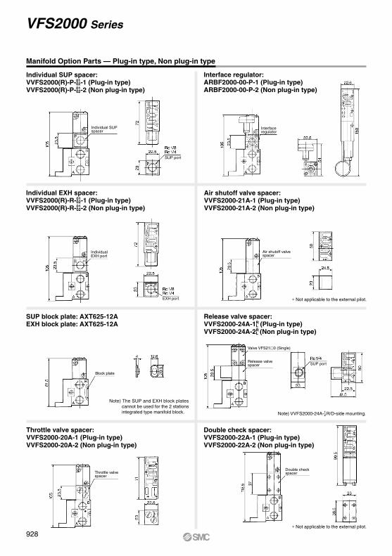
∗ Not applicable to the external pilot.
∗ Not applicable to the external pilot.
Note) The SUP and EXH block plates cannot be used for the 2 stations integrated type manifold block.
Manifold Option Parts — Plug-in type, Non plug-in type
Individual SUP spacer:VVFS2000(R)-P-01
02-1 (Plug-in type)VVFS2000(R)-P-01
02-2 (Non plug-in type)
Individual EXH spacer:VVFS2000(R)-R-01
02-1 (Plug-in type)VVFS2000(R)-R-01
02-2 (Non plug-in type)
SUP block plate: AXT625-12AEXH block plate: AXT625-12A
Throttle valve spacer:VVFS2000-20A-1 (Plug-in type)VVFS2000-20A-2 (Non plug-in type)
Release valve spacer:VVFS2000-24A-1R
L (Plug-in type)VVFS2000-24A-2R
L (Non plug-in type)
Double check spacer:VVFS2000-22A-1 (Plug-in type)VVFS2000-22A-2 (Non plug-in type)
Interface regulator:ARBF2000-00-P-1 (Plug-in type)ARBF2000-00-P-2 (Non plug-in type)
Air shutoff valve spacer:VVFS2000-21A-1 (Plug-in type)VVFS2000-21A-2 (Non plug-in type)
Note) VVFS2000-24A- R/D-side mounting.12
Individual SUP spacer
Interface regulator
Individual EXH port
Block plate
Throttle valve spacer
Release valve spacer
Valve VFS210 (Single)
SUP port
Double check spacer
EXH port
Air shutoff valve spacer
SUP port
928
VFS2000 Series

Manifold Specifications
Control Unit Specifications Control Unit/Option
CautionWhen using an air filter with auto-drain or manual drain, mount the filter vertically.
VV5FS2 10 08 1 01 APVFS2000 Series
Manifold
Control unit type
Air release valve coil rating
Q
CE-compliantNil —
CE-compliant
Nil159
0101T01C01F10
Symbol Applicable base
DNil
U01C, 01F
01, 01T, 10
With connector
D side mountingNone
U side mounting
Connector mounting direction
Base type/Electrical entry
Port size
Thread type
How to OrderNote) The manifold of plug-in type with attachment plug lead wire is applied to individual type only.
Non plug-in type has no junction cover.
How to Order Manifold Assembly [Example]Add the valve and option part numbers in order starting from the first station on the D side.
Manifold with Control Unit
Manifold
Wiring
Applicable valve model
Porting specificationsRc
Stations
Plug-in type: VV5FS2-01 Non plug-in type: VV5FS2-10Plug-in with attachment plug lead wire
With terminal blockWith multi-connectorWith D-sub connector
GrommetGrommet terminalConduit terminal
DIN terminal
VFS200-F (Z)VFS210-G, VFS210-EVFS210-T, VFS210-D
Common SUP, Common EXHSide: 1/8, 1/4, Bottom: 1/8 (Option)
Side: 1/4, 1/8, Bottom: 1/8 (Option)2 to 15 stations∗
∗ With multi-connector, or D-sub connector: 8 stations max.
2(B), 4(A) port1 (P), 3(R2), 5(R1) port
• Control unit (Filter, Regulator, Pressure switch, Air release valve) are all standardized to the one unit, and can be mounted on the manifold base without any attachments.
• Piping processes are eliminated.
Plug-in type
Non plug-in type
Air filter (With auto-drain/With manual drain)Filtration degreeRegulatorSet pressure (Outlet pressure)Pressure switch (1)
Set pressure range: OFFDifferentialContact
Max. switch capacity
Max. operating current
Air release valve (Single only)Operating pressure range
5 µm
0.05 to 0.85 MPa
0.1 to 0.6 MPa
0.1 to 1.0 MPa
0.08 MPa or less1a
Indicator light LED (RED)2 VA AC, 2 W DC
24 VAC/DC or less: 50 mA100 VAC/DC: 20 mA
Air releasevalve spacer
Pressure switch (3)
Blankingplate
Filter element
<Plug-in type>VVFS2000-24A-1R (D side mounting)VVFS2000-24A-1L (U side mounting)<Non plug-in type>VVFS2000-24A-2R (D side mounting)VVFS2000-24A-2L (U side mounting)
IS1000P-2-1With control unit/Filter regulator
Pressure switchRelease valve
MP2-2MP3-2
AXT625-18A111511-5B
Note 1) Voltage: 24 VDC to 100 VACInner voltage drop: 4 V
Note 2) Refer to manifold option parts on page 924.Note 3) The non plug-in type cannot be mounted afterwards.
Air filter with auto-drainControl equipment
Symbol
Air filter with manual drainRegulatorAir release valvePressure switchBlanking plate (Air release valve)
Blanking plate (Pressure switch)
Number of manifold blocksrequired for mounting (stations)
2
Blanking plate (Filter, Regulator)
2 2 2 2 2 2 1
Nil A AP M MP F G C E
None (F, G type only)100 VAC, 50/60 Hz
24 VDCOther
Plug-in type with attachment plug lead wirePlug-in type with terminal block
Plug-in type with multi-connectorPlug-in type with D-sub connector
Non plug-in type
2 stations
15 stations
02
15∗
Stations
Stacking typeIntegrated type
Nil1
Junction cover
∗ Base type01, 01T, 10 2 to 15 stations01C, 01F 2 to 8 stations
(Manifold base)(2 position single)
Symbol
Symbol
1 Side2∗ Bottom3∗ Side4∗ Bottom5∗ Side6∗ Bottom7∗ Side8∗ Bottom
Passage Portingspecifications
B, AEA, EBP
CommonCommon
IndividualCommon
CommonIndividual
IndividualIndividual
<Example>• Plug-in type with terminal block(Manifold base)(2 position single)(2 position double)∗ 2 stations are needed to mount control unit.
• Non plug-in type
∗ 2 stations are needed to mount control unit.
152
15
VV5FS2-01T1-091-02-MP5VFS2100-5FZVFS2200-5FZ
VV5FS2-10-071-01-MVFS2110-5D
The individual specification of the P port in the composition symbol marks 3 to 8 or EA, EB ports should be taken as individual port using a block plate. Therefore, if an individual port is taken using a single SUP spacer of option or a single EXH spacer, the composition symbol mark is “1”.
Note) Stacking type: Base type 01, 01T Integrated type: Base type 01T, 01C, 01F
∗ Semi-standard
Symbol
0102
B, AP, EA, EB
M Mixed
1 41 4
1 8
NilN∗
RcNPT
NPTFG
T∗F∗
∗ Semi-standard
··· ···
(2)
The asterisk denotes the symbol for assembly. Prefix it to the part numbers of the solenoid valve.
∗ ∗
∗
[Option]
Regulator with filter
Manually operatedAuto-drain type
INA-13-794GINA-13-806G
929
VFS2000 Series5 Port Pilot Operated Solenoid Valve
Metal Seal, Plug-in/Non Plug-in
SV
SYJ
SZ
VF
VP4VQ1/2
VQ4/5
VQC1/2
VQC4/5
VQZ
SQ
VFS
VFR
VQ7
VFS
B

X
Pressure switch
P
P'
Individual EXH spacer
Double check spacer
Individual EXH spacer
P'
R'
2(B)
4(A)
2(B)
4(A)
2(B)
4(A)
Control unit
(VVFS2000-P-01 02-1 2)
(VVFS2000-22A-1 2)
(VVFS2000-R-01 02-1 2)
Po P"3(R2)
1(P)
5(R1)
X
Pressure switch
P
P'
Individual EXH spacer
Double check spacer
Individual EXH spacer
P'
R'
2(B)
4(A)
2(B)
4(A)
2(B)
4(A)
Control unit
(VVFS2000-P-01 02-1 2)
(VVFS2000-22A-1 2)
(VVFS2000-R-01 02-1 2)
Po P"3(R2)
1(P)
5(R1)
Example for manifold
Manifold with Control Unit — Plug-in type, Non plug-in type
Plug-in type:Example for manifold
StationsL
L1
L2
3 131 140
4159168
5187196
6215224
7243252
8271280
9299308
10327336
FormulaL1 = 28 x n + 47L2 = 28 x n + 56
L3 (MP) 278 306 334 362 390 418 446 474 L3 = 28 x n + 194L3 (AP) 319.5 347.5 375.5 403.5 431.5 459.5 487.5 515.5 L3 = 28 x n + 235.5
n: Stations
Stations
Stations
Pressure switch
With light/surgevoltagesuppressor
Control unit
Pilot EXH port
Pilot EXH port
Electrical entry
Pressure switchelectrical entry
Po port
Po port
1(P), 3(R2), 5(R1) port
Outlet for check
Air
rele
ase
valv
eA
ir fil
ter
regu
lato
r
Outlet for check
Air
rele
ase
valv
eA
ir fil
ter
regu
lato
r
Pressure switch
Air release valve
A, B port
Non plug-in type:
Station Port size Control unit Voltage for release valveVV5FS2-01T- 1- -
Station Port size Control unit Voltage for release valveVV5FS2-10- 1- -
1(P), 3(R2), 5(R1) port
U side
D side
U side
D side
Air release valve
930
VFS2000 Series

∗ For 01WTB, please specify the number of stations mounted on the valve.(2 stations mounted on the ter-minal block are not included.)
[Option]
Dripproof Manifold (Equivalent to IP65)
How to order manifold
How to order valves
VV5FS2
Plug-in dripproof manifold(Equivalent to IP65)
101WTBU 08 02
2 stations
15 stations
02
15
Stations
Common terminal box (U side mounting)Common terminal box (D side mounting)
01WTBU01WTBD
Attachment plug lead wire01W
Symbol
Symbol
SideBottom
PassageP, R1, R2 A, B
Common
Port sizeSymbol
0102
A, BP, R1, R2
M
12∗
How to Order
X5400VFS2 F51
NilR∗
Pilot type
123456
Symbol
123∗4∗56∗7∗
∗ Semi-standardFor other rated voltages, please consult with SMC.
Pilot valve manual override
Dripproof
Coil rated voltage
Nil None
ZWith light/surge
voltage suppressor
Option∗Semi-standard
Manifold SpecificationsManifold
WiringApplicable value model
Porting specificationsRc
Stations
VV5FS2-01WTBU D VV5FS2-01W
Common terminal box Attachment plug lead wireVFS200-F-X54
Common SUP, Common EXHSide: 1/8, 1/4, Bottom: 1/8 (Option)
Side: 1/42 to 10 stations 2 to 15 stations
2(B), 4(A) port1(P), 3(R2), 5(R1) port
∗ Semi-standard
Mixed
1 41 4
1 8
∗ For bottom ported, A/B port is available only with .1 8
Internal pilot
External pilot
2 position single2 position double
3 position closed center3 position exhaust center3 position pressure center3 position double check
100 VAC, 50/60 Hz200 VAC, 50/60 Hz
110 to 120 VAC, 50/60 Hz220 VAC, 50/60 Hz
24 VDC12 VDC
240 VAC, 50/60 Hz
∗ Semi-standard
Nil
B∗A∗
Non-locking push type (Flush)Non-locking push type (Extended)
Locking type (Tool required)
C∗ Locking type (Lever)
Q
CE-compliantNil —
CE-compliant
•••
••
•
Portingspecifications
Q
CE-compliantNil —
CE-compliant
931
VFS2000 Series5 Port Pilot Operated Solenoid Valve
Metal Seal, Plug-in/Non Plug-in
SV
SYJ
SZ
VF
VP4VQ1/2
VQ4/5
VQC1/2
VQC4/5
VQZ
SQ
VFS
VFR
VQ7
VFS
A

Dripproof Manifold
∗ Terminal mounting stations are not included. Indicates solenoid valve mounting stations.
Bottom ported: VV5FS2-01WTBD- 2-01
StationsL
L1
L2
1120131
2145156
3170181
4195206
5220231
6245256
7270281
8295306
9320331
10345356
FormulaL1 = 25 x n + 95L2 = 25 x n + 106
n: Stations
Bottom ported: VV5FS2-01W- 2-01
StationsL
L1
L2
17081
295
106
3120131
4145156
5170181
6195206
7220231
8245256
9270281
10 11 12 13 14 15295306
320331
345356
370381
395406
420431
FormulaL1 = 25n + 45L2 = 25n + 56
n: Stations
With common terminal box: VV5FS2-01WTB - 1-UD
1(P), 3(R2), 5(R1) port
1(P), 3(R2), 5(R1) portInsert plug with lead wireLead wire length L = 1000
x 25 Printed
Electrical entry
Electrical entry
2(B), 4(A) port
2(B), 4(A) port
External pilot port
External pilot port
Pilot EXH port
Pilot EXH port
Push type manual override
Push type manual override
Indicator light
Indicator light
Stations
Stations
158 (
3 p
ositio
n)
150.5
(D
ouble
)101 (
Sin
gle
)
158 (
3 p
ositio
n)
150.5
(D
ouble
)101 (
Sin
gle
)
Station Port size
With attachment plug lead wire: VV5FS2-01W- 1-Station Port size
Station
Station
U sideD side
U sideD side
932
VFS2000 Series

933
SV
SYJ
SZ
VF
VP4VQ1/2
VQ4/5
VQC1/2
VQC4/5
VQZ
SQ
VFS
VFR
VQ7
VFS

08
Correspondence of SI unit output numbers and solenoid valve coils
How to Order
VV5FS2 X46001S
Applicable modelsSI unit part no.
—EX123U-SUH1EX124U-SDN1EX124U-SCS1EX124U-SCS2EX124U-SMJ1
DescriptionWithout SI unitNKE Corporation: Fieldbus H System (16 outputs)DevieNet (2 power supply systems)OMRON Corporation: CompoBus/S (16 outputs) (2 power supply systems)OMRON Corporation: CompoBus/S (8 outputs) (2 power supply systems) CC-Link (2 power supply systems)
Symbol0HQR1R2V
Nil RcNPT
NPTFG
Thread type
NTF
VFS2 00 5 F
<Wiring Example 1> Double wiring (Standard)
Plug-in typeSerial transmission kit
Stations03
18
3 stations
18 stationsNote 1) Max. 18 stations. Add 2 stations for serial unit
mounting.Note 2) Max. 18 stations for all-single wiring. (No. of
valves: 16)For the standard double wiring, the maximum number of stations is 10. (No. of valves: 8)
Combination symbol
Symbol
SideBottom
SideBottom
SideBottom
SideBottom
Port specificationP R1, R2
Piping specificationA, B
Common
Individual
Common
Individual
Common
Common
Individual
Individual
12∗
3∗
4∗
5∗
6∗
7∗
8∗
∗ Semi-standard
Port sizeSymbol
0102M
A, BP, R1, R2
1/4
∗ For bottom ported: 1/8 only
1/81/4
Mixed
Compatible with SI unit U sidemounating only
D side
Dou
ble
Dou
ble
Sin
gle
Sin
gle
Sin
gle
Dou
ble
Sin
gle
Sin
gle
SI u
nit
1
A B
2
A B
3
A B
4
A B
5
A B
6
A B
7
A B
8
A B
0 1 2 3 4 5 6 7 8 9 10 11 12 13 14 15
9 10
SI u
nit o
utpu
t no.
U side
<Wiring Example 2> Single/Double mixed wiring (Semi-standard)
∗ Mixed wiring is available as a semi-standard. Use the manifold specification sheet to specify this.
D side
Dou
ble
Dou
ble
Sin
gle
Sin
gle
Sin
gle
Dou
ble
Sin
gle
Dou
ble
Sin
gle
Sin
gle
SI u
nit
1
A B
2
A B
3
A
4
A
5
A
6
A B
7
A
8
A B
9
A
10
A
0 1 2 3 7 84 5 9 11 126
11 12
SI u
nit o
utpu
t no.
10 11
24 VDC
Symbol123456
2 position single2 position double
3 position closed center3 position exhaust center3 position pressure center3 position double check
Nil Non-locking push type (Flush)Non-locking push type (Extended)
Locking type (Tool required)Locking type (Lever)
Pilot valve manual override
ABC
Nil NoneWith light/surge voltage suppressor
Option
Z
Nil NoneCoil rated voltage
How to Order Manifold
How to Order Valves
V 1 02
Made to OrderSerial Transmission Kit Manifold: EX123/124 Integrated-type (For Output) Serial Transmission System
U side
Refer to Best Pneumatics No. 1-1 and the Op-eration Manual for the details of EX123/124 Inte-grated-type (For Output) Serial Transmission System. Please download the Operation Manu-al via our website, http://www.smcworld.com
934
VFS2000 Series
B

B
A
B
A
B
A
B
A
B
A
L2
L1
SMCP
EA
EB
R2
PE
R1
SMC
B
A
B
A
B
A
B
A
B
A
B
A
B
A
B
A
SMCSMC SMC SMC
Serial Transmission Kit Manifold: EX123/124 Integrated-type (For Output) Serial Transmission System
VV5FS2-01S Model - Stations Symbol - Port size -X460
Dimensions n: Stations (Max. 18 stations)Formula L1 = 28n + 47 L2 = 28n + 56
LL1
L2
n 3131140
4159168
5187196
6215224
7243252
8271280
9299308
10327336
11355364
12383392
13411420
14439448
15467476
16495504
17523532
18551560
Note) Actual number of manifold base stations: Add 2 SI unit mounting stations to the number of valve stations.
5.4
R2.7
6844
79
119.
5
158
150.
5
10175
Manual overrideSI unit
38
30.5
16.5
26.5
13
8.5
14.522
.514
.5
40.5
63
119.
5
127.
5
2 x Rc 1/8
1(P), 5(R1), 3(R2) port6 x Rc 1/4
PE port
1 2 3 4 5 6 7 8 nStationsD side U side
37.52842
123.
5
88.5
47
11.5
37.5
92
4(A), 2(B) port2n x Rc 1/8, 1/4
EX124: 4 x G 1/2
Electrical entry
EX123: 2 x G 1/2
∗ Use a dripproof plug assembly (AXT100-B04A) for the unused conduit port (G 1/2).
935
VFS2000 Series5 Port Pilot Operated Solenoid Valve
Metal Seal, Plug-in/Non Plug-in
SV
SYJ
SZ
VF
VP4VQ1/2
VQ4/5
VQC1/2
VQC4/5
VQZ
SQ
VFS
VFR
VQ7
VFS

!0 D side
U side
Not used for the 1st station on D side.
1 station2 stations 2 stations
1 station1 station2 stations2 stations
<5 stations (Odd number)>
<6 stations (Even number>
Example) U side D side123456n
• Manifold base is consisted of the junction of 2 and 3 station bases.
• For increasing the manifold bases, please order the manifold block assembly number of the principle number assembly !1 and !2. For plug-in type: The manifold base with terminal stand (integrated with a junction cover) is required with the !0 junction cover assembly.
∗ Manifold Base/Construction: Plug-in type with terminal block (01T1).
R1
R2
EB
P
EAPE
SMC
!3
wq
e
!2
!1u
yi
r!4
o
!5
t
!6
Manifold Base Construction — Plug-in type, Non plug-in type
936
VFS2000 Series

Replacement PartsNo. Description Material Part no.1 Steel plateConnection fitting assembly AXT625-4-1A2 Connection fitting B Steel plate AXT625-53 Gasket A NBR AXT625-174 Gasket B NBR AXT625-16
6 O-ring NBR KA00292KA00276KA00326
7 O-ring NBR8 O-ring NBR
Adapter plate Resin AXT625-6AXT625-28-13A(Terminal section with adapter plate and lead wire assembly)
AXT625-28-1VVF2000-26-6AXT625-6AXT625-7AAXT625-28-3A
VVF2000-26-5A- AZ738-10A- AXT333-12AXT625-22
Plug EXP22S
9
10
15
Adapter plate assembly
Adapter plate
Junction cover assembly
Rubber plug
—
NBR
Resin
—
—
For 01For 01TFor 01T1For 01CFor 01F
For 01SFor 01
For 01TFor 01T1For 01CFor 01F
For 01SFor 01
For 01W
AXT625-28-7A- Stations
Stations
Stations
Replacement Parts: Sub AssemblyNo. Description Part no.
AXT625-01A- (-B) Note)
AXT625-20A- (-B) Note)
AXT625-10A- (-B) Note)
AXT625-2A
AXT625-2A-20
AXT625-2A-10
11
13End plate (U side)assembly
End plate (D side)assembly
Manifold blockassembly(for 1 station)
14
Applicable manifold basePlug-in type
With attachment plug lead wire
Plug-in typeWith terminal block
Non plug-in type
Plug-in typeWith attachment plug lead wire
Plug-in typeWith terminal block
Non plug-in type
Plug-in typeWith attachment plug lead wire
Plug-in typeWith terminal block
Non plug-in type
AXT625-3A
AXT625-3A-20
AXT625-3A-10
Component partsManifold block !1, Metal joint q, w, O-ring y, u, i, Junction cover !0, Adapter plate o, Pin housing, Guide, Insert plug lead wire
Manifold block !1, Metal joint q, w, O-ring y, u, i, Junction cover !0, Adapter plate assembly (with terminal) o, Pin housing, Guide
Manifold block !1, Metal joint q, w, O-ring y, u, i
End plate (U) !3, Metal joint q, w, Gasket A e, Guard !6
End plate (U) !3, Metal joint q, w, Gasket A e, Guard !6
End plate (U) !3, Metal joint q, w, Gasket A e
End plate (D) !4, Metal joint q, w, Gasket B r, Guard !6, Steel ball
End plate (D) !4, Metal joint q, w, Gasket B r, Guard !6, Steel ball
End plate (D) !4, Metal joint q, w, Gasket B r, Steel ball
Note) 1: A, B port size Rc 1/8, 2: A, B port size Rc 1/4, (-B): A, B port bottom ported
Gasket5 HNBR VVFS2000-32-1H
16 Guard Resin AXT625-28-4
AXT625-01A2- Note)
AXT625-20A2- Note)
AXT625-10A2- Note)
12Manifold blockassembly(for 2 stations)
Plug-in typeWith attachment plug lead wire
Plug-in typeWith terminal block
Non plug-in type
Manifold block !2, Metal joint q, w, Gasket t, Junction cover !0,Adapter plate o, Pin housing, Guide, Insert plug lead wire
Manifold block !2, Metal joint q, w, Gasket t, Junction cover !0,Adapter plate assembly (with terminal) o, Pin housing, Guide
Manifold block !1, Metal joint q, w, Gasket t
01T (1)01SFor
0101T (1)For
12
12
12
12
12
12
937
VFS2000 Series5 Port Pilot Operated Solenoid Valve
Metal Seal, Plug-in/Non Plug-in
SV
SYJ
SZ
VF
VP4VQ1/2
VQ4/5
VQC1/2
VQC4/5
VQZ
SQ
VFS
VFR
VQ7
VFS
A

Light Compact Type Sub-plate/C: 2.8 dm3/(s·bar)
TypeCompact typeStandard type
25.531
0.130.2
Sub-plateC: 2.2 dm3/(s·bar)
Compact type Standard type
Bottom ported
Sub-plate — Compact: Plug-in, Grommet (With attachment plug lead wire)
( ): Port size P02
Port Size
Bottom Ported Size
Sub-plate — Compact: Non plug-in
Precautions Please pay attention to piping port location of sub-plate.
( ): Port size S02
PortPort size
S01S02
P, A, BRcRc
1 81 4
EA, EBRcRc
1 81 8
PortPort size
BS02P, A, B
Rc 1 41 8
EA, EBRc 1 8
VFS210--(B)
Sub-plate assembly part no.: VFS2000-CP-(B) (01: Rc , 02: Rc )
L dimension(mm)
Weight(kg)
VFS200-F-(B) P01P02
S01S02
1 8 1 40102
Sub-plate assembly part no.: VFS2000-CS-(B) (01: Rc , 02: Rc )1 8 1 40102
PortPort size
P01P02
P, A, BRc Rc
1 81 4
EA, EBRc Rc
1 81 8
Port Size
Bottom Ported SizePortPort size
BP02P, A, B
Rc ,1 41 8
EA, EBRc 1 8
Solenoid
Lead wire color Red Black Brown WhiteA side B side
• There is no polarity.
C: 2.8 dm3/(s·bar)
VFS20-- : Compact typeP01/02S01/02 VFS20-- : Standard type01
02
Electrical Connection
L dimension
1 (Center)Pilot EXH port
1 (Center)
Pilot EXH port
5 x bottom ported size (Refer to the right.)
5 x bottom ported size (Refer to the right.)
5 x bottom ported size(Refer to the below right.)
2 x ø4.5 mounting hole
2 x ø4.5 mounting hole
Lead wire
≈ 300
5 x bottom ported size(Refer to the below right.)
Electrical entry
Bottom ported
Compact type, plug-in type grommet sub-plate (With attachment plug lead wire)• The attachment plug lead wire is attached to the
manifold block and lead wire is plugged in with valve side as shown in the following list. Please connect with corresponding power side.
L dimension
938
VFS2000 Series

939
SV
SYJ
SZ
VF
VP4VQ1/2
VQ4/5
VQC1/2
VQC4/5
VQZ
SQ
VFS
VFR
VQ7
VFS
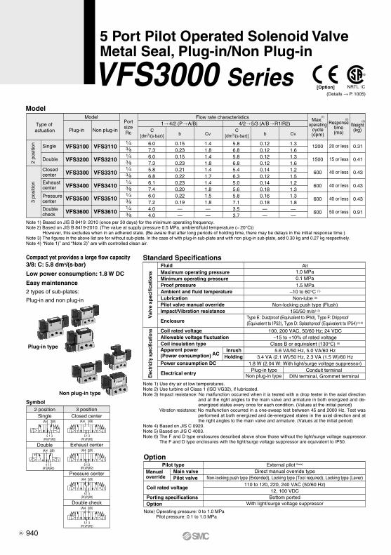
5(R1)
3(R2)
1(P)
(A)4 2(B)
(A)4 2(B)
3(R2)
1(P)
5(R1)
3(R2)
5(R1)
1(P)
2(B)(A)4
(A)4 2(B)
3(R2)
1(P)
5(R1)
(A)4 2(B)
3(R2)
1(P)
5(R1)
(A)4 2(B)
3(R2)
1(P)
5(R1)
Model
Standard Specifications
Option
Symbol
Type of actuation
Model
Plug-in Non plug-in
VFS3100
VFS3200
VFS3300
VFS3400
VFS3500
1 43 81 43 81 43 81 43 81 43 8
1200
1500
600
600
600
VFS3600
VFS3110 6.07.36.07.35.86.86.17.46.07.24.04.0
0.150.230.150.230.210.220.230.200.220.19——
1.41.81.41.81.41.71.41.81.51.8——
5.86.85.86.85.46.35.05.65.87.13.53.7
0.120.120.120.120.140.120.140.180.160.18——
1.31.61.31.61.21.51.21.31.31.8——
VFS3210
VFS3310
VFS3410
VFS3510
VFS36101 43 8
600
0.31
0.41
0.43
0.43
0.43
0.91
C[dm3/(s·bar)]
C[dm3/(s·bar)]b Cv b Cv
1 4/2 (P A/B) 4/2 5/3 (A/B R1/R2) Flow rate characteristics
Pilot typeManualoverride
Main valvePilot valve
Coil rated voltage
Porting specificationsOption
2 positionSingle
Double
3 positionClosed center
Exhaust center
Pressure center
Double check
Compact yet provides a large flow capacity3/8: C: 5.8 dm3/(s·bar)
Low power consumption: 1.8 W DC
Easy maintenance2 types of sub-plates:
Plug-in and non plug-in
Plug-in type
Non plug-in type
2 po
sitio
n3
posi
tion
Single
Double
Closedcenter
Pressure center
Exhaust center
PortsizeRc
20 or less
15 or less
40 or less
40 or less
40 or less
Note 1) Based on JIS B 8419: 2010 (once per 30 days) for the minimum operating frequency.Note 2) Based on JIS B 8419-2010. (The value at supply pressure 0.5 MPa, ambient/fluid temperature (≈ 20°C))
However, this excludes when in an adhered state. (Be aware that after long periods of holding time, there may be delays in the initial response time.)Note 3) The figures in the above list are for without sub-plate. In the case of with plug-in sub-plate and with non plug-in sub-plate, add 0.30 kg and 0.27 kg respectively. Note 4) “Note 1)” and “Note 2)” are with controlled clean air.
Doublecheck 50 or less
FluidMaximum operating pressureMinimum operating pressureProof pressureAmbient and fluid temperatureLubricationPilot valve manual overrideImpact/Vibration resistance
Enclosure
Coil rated voltageAllowable voltage fluctuationCoil insulation typeApparent power(Power consumption)
Power consumption DC
InrushHolding
Electrical entry
Val
ve s
pec
ific
atio
ns
Elec
tric
ity s
peci
ficat
ions
Air
1.5 MPa–10 to 60°C (1)
Non-lube (2)
Non-locking push type (Flush)150/50 m/s2 (3)
Type E: Dustproof (Equivalent to IP50), Type F: Dripproof (Equivalent to IP52), Type D: Splashproof (Equivalent to IP54) (4) (6)
100, 200 VAC, 50/60 Hz; 24 VDC–15 to +10% of rated voltage
Class B or equivalent (130°C) (5)
5.6 VA/50 Hz, 5.0 VA/60 Hz3.4 VA (2.1 W)/50 Hz, 2.3 VA (1.5 W)/60 Hz
1.8 W (2.04 W: With light/surge voltage suppressor)Plug-in type
Non plug-in type
1.0 MPa0.1 MPa
Note 1) Use dry air at low temperatures.Note 2) Use turbine oil Class 1 (ISO VG32), if lubricated.Note 3) Impact resistance: No malfunction occurred when it is tested with a drop tester in the axial direction
and at the right angles to the main valve and armature in both energized and de-energized states every once for each condition. (Values at the initial period)
Vibration resistance: No malfunction occurred in a one-sweep test between 45 and 2000 Hz. Test was performed at both energized and de-energized states in the axial direction and at the right angles to the main valve and armature. (Values at the initial period)
Note 4) Based on JIS C 0920. Note 5) Based on JIS C 4003.Note 6) The F and D type enclosures described above show those without the light/surge voltage suppressor.
The F and D type enclosures with the light/surge voltage suppressor are equivalent to IP50.
AC
Conduit terminalDIN terminal, Grommet terminal
External pilot Note)
Direct manual override typeNon-locking push type (Extended), Locking type (Tool required), Locking type (Lever)
110 to 120, 220, 240 VAC (50/60 Hz)12, 100 VDC
Bottom portedWith light/surge voltage suppressor
Note) Operating pressure: 0 to 1.0 MPa Pilot pressure: 0.1 to 1.0 MPa
Max. operating
cycle(cpm)
Responsetime(ms)
(Details → P. 1005)
Weight(kg)
(1)(2)
(3)
[Option]
940
5 Port Pilot Operated Solenoid ValveMetal Seal, Plug-in/Non Plug-in
VFS3000 Series
A

(A)4 2(B)
3(R2)
1(P)
5(R1)
(A)4 2(B)
3(R2)
1(P)
5(R1)
(A)4 2(B)
3(R2)
1(P)
5(R1)
3(R2)
5(R1)
1(P)
2(B)(A)4
5(R1)
3(R2)
1(P)
(A)4 2(B) (A)4 2(B)
3(R2)
1(P)
5(R1)
[Option]
1 02FPlug-in VFS3 1
D
Q
CE-compliantNil —
CE-compliant
Non plug-in VFS3
Symbol
1
2 position single
2
2 position double
3
3 position closed center
4
3 position exhaust center
5
3 position pressure center
6
3 position double check
O: Plug-in typesub-plate
1: Non plug-in type sub-plate
Body type
Pilot valveManual override
Portingspecifications
Port sizeNil0203
Thread typeNilN∗ NPT
Rc
T∗ NPTFF∗ G
∗ Semi-standard
Pilot typeNilR∗
Internal pilotExternal pilot
∗ Semi-standard
Body Option01∗
StandardDirect manual override
∗ Semi-standard
Coil rated voltage123∗4∗56∗7∗
∗ Semi-standard
02
0 0
2
Body type
OptionNilZ
NoneWith light/surge voltage suppressor
F: Plug-in typeconduit terminal
Electrical entry
E: Grommet terminal D: DIN terminalDO: DIN terminal without connector
Electrical entry
2 1 1
Rated voltage
∗ Semi-standard
Manual override Coil rated voltage
SF4 F1 30
How to Order Pilot Valve Assembly
How to Order
NilB∗
Side portedBottom ported
∗ Semi-standard
Without sub-plate1 4
1 4
3 8
100 VAC, 50/60 Hz200 VAC, 50/60 Hz
110 to 120 VAC, 50/60 Hz220 VAC, 50/60 Hz
24 VDC12 VDC
240 VAC, 50/60 Hz
Nil: Non-locking push type(Flush)
A∗: Non-locking push type(Extended)
B∗: Locking type (Tool required)
C∗: Locking type(Lever)
1 100 VAC, 50/60 Hz
Symbol Symbol Manual override
2 200 VAC, 50/60 Hz3∗ 110 to 120 VAC, 50/60 Hz4∗ 220 VAC, 50/60 Hz5 24 VDC6∗ 12 VDC7∗ 240 VAC, 50/60 Hz
Nil
B∗
A∗
Non-locking push type(Flush)
Non-locking push type(Extended)
Locking type (Tool required)
C∗ Locking type (Lever)
∗ For bottom ported, is only available.
∗ Reverse pressure: Can be used by external pilot specifications.
For other rated voltages, please consult with SMC.∗∗ Refer to page 1010 for voltage conversion.
∗ Semi-standard
∗ Semi-standard For other rated voltages, please consult with SMC.
941
VFS3000 Series5 Port Pilot Operated Solenoid Valve
Metal Seal, Plug-in/Non Plug-in
SV
SYJ
SZ
VF
VP4VQ1/2
VQ4/5
VQC1/2
VQC4/5
VQZ
SQ
VFS
VFR
VQ7
VFS
A

System
A
800700600500400300200100 0
B
800
900
900
1000
1000
700600500400300200100 0
Bore size
ø40 ø50 ø63 ø80 ø100 ø125 ø140 ø160 ø180 ø200
System Components
Double Check Spacer/Specifications
Specifications Check Valve Operation
Caution
Double check spacer
Cylinder Speed Chart
Can hold an intermediate cylinder position for an extended timeIf the double check spacer with a built-in double check valve is combined, it will enable the cylinder to stop in the intermediate stroke and maintain its position for a long time without being affected by the leakage between the spools. • In the case of 3 position double check
valve (VFS360), check the leakage from piping and fittings in between valve and cylinder by means of synthetic detergent solutions, and ensure that there is no such leakage found there. Also check the leakage from cylinder seal and piston seal. If there is any leakage, sometimes the cylinder, when valve is de-energized, can move without stopping at intermediate position.
• Be aware that if the exhaust side is restricted excessively, the intermediate stopping accuracy will decrease and will lead to improper intermediate stops.
• The combination of VFS31 0, VFS32 0 and double check spacer can be used as prevention for falling at the stroke end but cannot hold the intermediate position of the cylinder.
VFS3000SeriesRc
System
A
B
Solenoid valveSpeed
controller
VFS3000SeriesRc 1 4
3 8
AS4000-02(S = 24 mm2)
AS420-03(S = 73 mm2)
Silencer
AN20-02(S = 35 mm2)
AN30-03(S = 60 mm2)
SGP (Steel pipe)Port size x Length
6A x 1 m
10A x 1 m
Plug-in type
Non plug-in type
Double checkspacer part no.
Applicablevalve model
Plug-in typeVVFS3000-22A-1
VFS3400-F
Non plug-in typeVVFS3000-22A-2
VFS3410-DVFS3410-E
Averagespeed(mm/s)
MB, CA2 seriesPressure 0.5 MPaLoad factor 50%Stroke 500 mm
CS1/CS2 seriesPressure 0.5 MPaLoad factor 50%Cylinder stroke 1000 mm
Perpendicular,upward actuationHorizontalactuation
Use as a guide for selection.Please confirm the actual conditions with SMC Sizing Program.
∗ It is when the cylinder is extending that is meter-out controlled by speed controller which is directly con-nected with cylinder, and its needle valve with be-ing fully open.
∗ The average velocity of the cylinder is the value that the stroke is divided by the total stroke time.
∗ Load factor: ((Load mass x 9.8)/Theoretical force) x 100%
01
01
Check valve
Piston SUP side pressure (P1)
Operating range
Cylinder side pressure P2 (MPa)
Cylinder side pressure (P2)
SU
P s
ide
pres
sure
P1
(MP
a)
942
VFS3000 Series
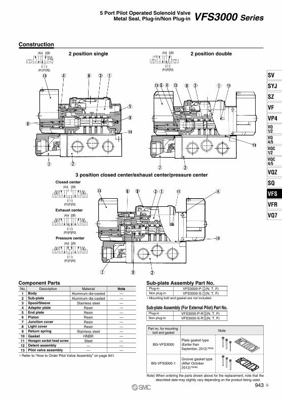
(A)4 2(B)
3(R2)
1(P)
5(R1)
(A)4 2(B)
3(R2)
1(P)
5(R1)
(A)4 2(B)
3(R2)
1(P)
5(R1)
3(R2)
5(R1)
1(P)
2(B)(A)4
5(R1)
3(R2)
1(P)
(A)4 2(B)
Construction
Sub-plate Assembly Part No.
2 position single
3 position closed center/exhaust center/pressure center
2 position double
∗ Mounting bolt and gasket are not included.
Component PartsNo.
23
1Aluminum die-casted
Stainless steel
MaterialAluminum die-casted
4 Resin
——
—
—5 Resin —6 Resin —7 Resin —8 Resin —9 Stainless steel —10 HNBR —11 Steel —12 — —13 — —
∗ Refer to “How to Order Pilot Valve Assembly” on page 941.
Closed center
Exhaust center
Pressure center
Description
Sub-plateBody
Spool/SleeveAdapter plateEnd platePistonJunction coverLight coverReturn springGasket
Pilot valve assembly
Hexagon socket head screwDetent assembly
Plug-inNon plug-in
VFS3000-P- (N, T, F)VFS3000-S- (N, T, F)
02030203
Sub-plate Assembly (For External Pilot) Part No.Plug-inNon plug-in
VFS3000-P-R (N, T, F)VFS3000-S-R (N, T, F)
02030203
NoteNote
Note) When ordering the parts shown above for the replacement, note that the described date may slightly vary depending on the product being used.
Note
BG-VFS3000-1
BG-VFS3000
Groove gasket type(After October 2012) Note)
Plate gasket type(Earlier than September, 2012) Note)
Part no. for mounting bolt and gasket
943
VFS3000 Series5 Port Pilot Operated Solenoid Valve
Metal Seal, Plug-in/Non Plug-in
SV
SYJ
SZ
VF
VP4VQ1/2
VQ4/5
VQC1/2
VQC4/5
VQZ
SQ
VFS
VFR
VQ7
VFS
A

Plug-in — 2 Position single/3 Position closed center/Exhaust center/Pressure center/Double check
2 position single: VFS3100-F(Z)
2 position double: VFS3200-F(Z)3 position closed center: VFS3300-F(Z)3 position exhaust center: VFS3400-F(Z)3 position pressure center: VFS3500-F(Z)
3 position double check: VFS3600-F(Z)
Bottom ported
2 x ø5.6 mounting hole
2 x ø5.6 mounting hole
2 x ø5.6mounting hole
Pilot valve manual override
G 1/2 electrical entry
170.5 (3 position: 175)
86.5 (3 position: 96.5)
Pilot valvemanual override
Pilot valvemanualoverride
With
dire
ct m
anua
l ove
rrid
e
With
dire
ct m
anua
l ove
rrid
eLight window
With
dire
ct m
anua
l ove
rride
At FZ
Light windowAt FZ
Light windowAt FZ
Rc 1/8 external pilot port(Only for external pilot) 2(B), 4(A) port
G 1/2 electrical entryG 1/2 electrical entry
(PE port)
2 x ø5.6mounting hole
1 4( ): Rc
1 4( ): Rc 1 4( ): Rc
944
VFS3000 Series
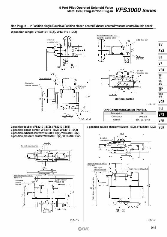
No.
UKL-S1DXT087-27-2
ConnectorGasket
DIN Connector/Gasket Part No.
Non Plug-in — 2 Position single/Double/3 Position closed center/Exhaust center/Pressure center/Double check
2 position single: VFS3110-E(Z), VFS3110-D(Z)
2 position double: VFS3210-E(Z), VFS3210-D(Z)3 position closed center: VFS3310-E(Z), VFS3310-D(Z)3 position exhaust center: VFS3410-E(Z), VFS3410-D(Z)3 position pressure center: VFS3510-E(Z), VFS3510-D(Z)
3 position double check: VFS3610-E(Z), VFS3610-D(Z)
Bottom ported
2 x ø5.6 mounting hole
2 x ø5.6 mounting hole
Light window at DZ, EZ
Applicable heavy-duty cord O.D.ø8 to ø10
Pilot valvemanual override
Applicable heavy-duty cord O.D.ø8 to ø10
Pilot valvemanual override
165 (3 position: 175)
2 x ø5.6 mounting hole
Rc 1/8 external pilot port(Only for external pilot)
2(B), 4(A) port
Light windowAt DZ, EZ
Light windowAt DZ, EZ
Cable ø8 to ø10
Pilot valve manual override
With
dire
ct m
anua
l ove
rrid
e
With
dire
ct m
anua
l ove
rrid
e
With
dire
ct m
anua
l ove
rrid
e
2 x ø5.6 mounting hole
1 4( ): Rc
1 4( ): Rc1 4( ): Rc
(PE port)
Description
945
VFS3000 Series5 Port Pilot Operated Solenoid Valve
Metal Seal, Plug-in/Non Plug-in
SV
SYJ
SZ
VF
VP4VQ1/2
VQ4/5
VQC1/2
VQC4/5
VQZ
SQ
VFS
VFR
VQ7
VFS

[Option]
Symbol
1 Side2 Bottom∗
Passage Portingspecifications
(A, B)EA, EBP
CommonCommon
Plug-in Type: With Terminal Block
Plug-in Type: With Multi-connector (Wiring specifications: Refer to page 1013.)
Plug-in Type: With D-sub Connector
Non Plug-in Type: Grommet Terminal, DIN Terminal
01TVV5FS3
Plug-in typewith terminal block
Symbol
0203
A, BP, EA, EB
M
106 02VFS3000 Series
Manifold
D01CVV5FS3
Plug-in typewith multi-connector
205 02VFS3000 Series
Manifold
D01FVV5FS3
Plug-in typewith D-subconnector
106 02VFS3000 Series
Manifold
10VV5FS3 205 02
• Since lead wires of solenoid valve are connected with the terminals on upper surface of terminal block, corresponding lead wires from power source can be wired at the bottom of terminal block.
• Master connection of power and solenoid valves.
• Quick wiring permits easier installation.
• Wide range of interchangeability(MIL Spec D-sub connector termi-nal 25 pcs attached.)
• Quick wiring permits easier installation.
• Wiring for every valve.
Mixed
3 81 2
1 4
∗ Semi-standard
Symbol
1 Side2 Bottom∗
Passage Portingspecifications
(A, B)EA, EBP
CommonCommon
∗ Semi- standard
∗ Semi- standard
Symbol
1 Side2 Bottom∗
Passage Portingspecifications
(A, B)EA, EBP
CommonCommon
D side mountingU side mounting
DU
(Wiring specifications: Refer to page 1013.)
1 station
16 stations
01
16
··· ···
∗ Max. 8 stations
Connector mountingdirection
Port sizeSymbol0203
A,BP,EA,EB
M Mixed
3 81 2
1 4
Nil RcNPTF
GT∗F∗
∗ Semi-standard
Thread type
Symbol
···
2 stations
8 stations
···
02
08∗
Stations
Q
CE-compliantNil —
CE-compliant
∗ For bottom ported, 1/4 is only available.
Symbol
1 Side2 Bottom∗
Passage Portingspecifications
(A, B)EA, EBP
CommonCommon
D side mountingU side mounting
DU
U side
D side
U side
D side
Terminal block
Plug assembly (Option)Refer to page 1013.
Plug assembly (Option)Refer to page 1013.
Multi-connector
D-sub connector
DIN terminal
Grommet terminal
Port size
Stations
Nil RcNPTF
G
T∗F∗
∗ Semi-standard
Thread type
Symbol
Q
CE-compliantNil —
CE-compliant
∗ For bottom ported, 1/4 is only available.
Connector mountingdirection Port size
Symbol0203
A,BP,EA,EB
M Mixed
3 81 2
1 4
Nil RcNPTF
GT∗F∗
∗ Semi-standard
Thread type
Symbol
···
2 stations
8 stations
···
02
08∗
Stations
∗ Max. 8 stations
Q
CE-compliantNil —
CE-compliant
∗ For bottom ported, 1/4 is only available.
Non plug-in typePort size
Symbol0203
A,BP,EA,EB
M Mixed
VFS3000 SeriesManifold
···
1 station
16 stations
···
01
16
Stations
3 81 2
1 4
∗ Semi-standard
Nil RcNPTF
GT∗F∗
∗ Semi-standard
Thread type
Symbol
Q
CE-compliantNil —
CE-compliant
∗ For bottom ported, 1/4 is only available.
946
VFS3000 Series
Manifold Specifications
A

Base model
Non plug-in typeVV5FS3-10
Wiring
• With terminal block• With multi-connector• With D-sub connector
• DIN terminal• Grommet terminal
A, B port
Side/Bottom
P, EA, EBPort size Rc
A, BStations
Externalpilot
YesVFS30(R)-F(Z)
VFS31(R)-D(Z)VFS31(R)-E(Z)
Flow Rate Characteristics at the Number of Manifold Stations (Operated individually)
How to Order Manifold Assembly
∗ Port size: Rc 3/8
Passage/Stations Station 1 Station 5 Station 106.0
0.20 1.4 7.0 0.20 1.8
6.0 0.20 1.4 7.0 0.20 1.8
6.0 0.20 1.4 7.0 0.20 1.8
Model
VV5FS3
Manifold SpecificationsPlease indicate manifold base type, corresponding valve, and option parts.
<Example>• Plug-in type with terminal block: 6 stations (Manifold base) VV5FS3-01T-061-02 ······ 1 (2 position single) VFS3100-5FZ ············ 3 (2 position double) VFS3200-5FZ ··········· 2 (Blanking plate) VVFS3000-10A ············· 1
<Example>• Non plug-in type: 6 stations (Manifold base) VV5FS3-10-061-03 ········ 1 (2 position single) VFS3110-5D ··············· 5 (3 position exhaust center) VFS3410-5D ····· 1 (Individual EXH spacer) VVFS3000-R-03-2 ··· 1
Plug-in typeVV5FS3-01
Portingspecifications Applicable
valve model
, 1 21 4 3 8 1 to 16
(1) (2) (3)
(3)
Note 1) Appropriate silencer for EA, EB port: “AN40-04”.Note 2) With multi-connector, or with D-sub connector: 8 stations max.Note 3) It is possible to mount the standard valve and the external pilot type valve together.
4/2 5/3(A/B R1/R2)
C [dm3/(s·bar)]
bCv
1 4/2(P A/B)
bC [dm3/(s·bar)]
Cv
947
VFS3000 Series5 Port Pilot Operated Solenoid Valve
Metal Seal, Plug-in/Non Plug-in
SV
SYJ
SZ
VF
VP4VQ1/2
VQ4/5
VQC1/2
VQC4/5
VQZ
SQ
VFS
VFR
VQ7
VFS

When mounting on the 2 stations integrated type manifold block, mount it after cutting the gasket.
Manifold Option Parts AssemblyIndividual SUP spacerAn individual SUP spacer set on manifold block can form SUP port for every valve.
Individual EXH spacerAn individual EXH spacer set on manifold block can form EXH port for every valve. (common EXH type)
∗ SUP block plateWhen supplying manifold with more than two different pressures, high and low, insert a block plate in between stations subjected to different pressures.
∗ EXH block plateWhen valve exhaust affects the other stations on the circuit or when the reverse pressure valve is used to standard manifold valve, insert EXH block plate between stations to separate valve exhaust.
Throttle valve spacerNeedle valve set on the manifold block can control cylinder speed by throttling exhaust.
Double check spacerIf the double check spacer with a built-in double check valve is combined, it will enable the cylinder to stop in the intermediate stroke and maintain its position for a long time without being affected by the leakage between the spools.
Blanking plateIt is used by attaching on the manifold block for being prepared for removing a valve for maintenance reasons or planning to mount a spare valve, etc.
Interface regulatorInterface regulator set on manifold block can regulate the pressure to each valve. (Refer to page 1011 for “Flow Rate Characteristics”.)
With control unitPlug-in type/Non Plug-in type• Filter, regulation valve, pressure switch
and air release valve are all combined to form one unit.
• Piping processes are eliminated.
For details, refer to page 951.
Made to OrderSerial transmission kit manifold Plug-in type• Solenoid valve wiring process reduced
considerably.
For details, refer to page 953.
For details, refer to page 956.
With exhaust cleanerPlug-in type/Non Plug-in type • Valve exhaust noise dampening: 35 dB
or more.• Oil mist collection: Rate of collection
99.9% or more.• Piping process reduced.
Manifold Option
Body type Plug-in typeVVFS3000-P-03-1
Non plug-in typeVVFS3000-P-03-2Part no.
Body type Plug-in typeVVFS3000-20A-1
Non plug-in typeVVFS3000-20A-2Part no.
Body type Plug-in typeVVFS3000-22A-1
Non plug-in typeVVFS3000-22A-2Part no.
Body type Plug-in typeVVFS3000-R-03-1
Non plug-in typeVVFS3000-R-03-2Part no.
Body type Plug-in typeAXT636-1A
Non plug-in typePart no.
Body type Plug-in typeAXT636-1A
Non plug-in typePart no.
Body type Plug-in typeVVFS3000-10A
Non plug-in typePart no.
Body type Plug-in typeARBF3050-00-P-1
Non plug-in typeARBF3050-00-P-2P port regulation
ARBF3050-00-A-1 ARBF3050-00-A-2A port regulationARBF3050-00-B-1 ARBF3050-00-B-2B port regulation
948
VFS3000 Series

Formula for manifold weight M = 0.405n + 0.665 (kg) n: Station
Manifold — Plug-in type, Non plug-in type
Non plug-in type: VV5FS3-10- 1-
Bottom ported:VV5FS3-01T- Station 2- Port size
Formula for manifold weight M = 0.309n + 0.532 (kg)Stations
L
L1
L2
2129141
3162174
4195207
5228240
6261273
7294306
8327339
9360372
10393405
FormulaL1 = 33 x n + 63L2 = 33 x n + 75
n: Stations
Plug-in type (With terminal block): VV5FS3-01T- 1-
Bottom ported:VV5FS3-10- Station 2- Port size
Station Port size
Station Port size
Stations
Stations
(Pilot EXH port: PE)
Electrical entry
(External pilot port)
Light window
Light window
Applicable cabtire cable O.D.ø8 to ø10
Pilot valve manual override
Pilot valve manual override
U side
D side
U side
D side
(External pilot port)(Pilot EXH port: PE)
949
VFS3000 Series5 Port Pilot Operated Solenoid Valve
Metal Seal, Plug-in/Non Plug-in
SV
SYJ
SZ
VF
VP4VQ1/2
VQ4/5
VQC1/2
VQC4/5
VQZ
SQ
VFS
VFR
VQ7
VFS

Formula for manifold weight M = 0.41n + 0.753 (kg) n: Station ∗ Wiring specifications: Refer to page 1013.
Formula for manifold weight M = 0.41n + 0.677 (kg) n: Station∗ Wiring specifications: Refer to page 1013.
Manifold — Plug-in type with multi-connector/D-sub connector
Plug-in type with D-sub connector: VV5FS3-01FD- Station 1- Port size , VV5FS3-01FU- Station 1- Port size
CDCU
StationsL
L1
L2
2129141
3162174
4195207
5228240
6261273
7294306
8327339
FormulaL1 = 33 x n + 63L2 = 33 x n + 75
n: Stations
Plug-in type with multi-connector: VV5FS3-01CD- Station 1- Port size , VV5FS3-01CU- Station 1- Port size
Bottom ported: VV5FS3-01 - Station 2- Port size
Bottom ported:VV5FS3-01 - Station 2- Port sizeFD
FU
(Pilot EXH port: PE)
Plug assembly VVZS3000-21A-(Option: Refer to page 1013.)
(External pilot port)
(Pilot EXH port: PE)(External pilot port)
Light window
Light window
Plug assembly VVFS2000-30A-(Option: Refer to page 1013.)
Pilot valve manual override
Pilot valve manual override
Stations
Stations
U side
D side
U side
D side
950
VFS3000 Series

[Option]
Manifold Specifications
Manifold with Exhaust Cleaner
Plug-in type
Non plug-in type
CautionWhen using an exhaust cleaner, mount it downwards.
∗ For details about exhaust cleaners, refer to Best Pneumatic No. 7.
Manifold
Wiring
Applicable valve model
Porting specificationsRc
Stations
Plug-in type: VV5FS3-01 Non plug-in type: VV5FS3-10
Applicable exhaust cleaners
Note 1) With multi-connector, or with D-sub connector: 8 stations max. Note 2) Exhaust cleaner “AMC610-10” is not attached.
10610 03 CDVFS3000 Series
Manifold
VV5FS3
Exhaust cleanermounting direction
Nil RcNPTF
G
T∗F∗
∗ Semi-standard
Thread type
Port size
How to Order
• Serves to protect workingenvironment.
• Valve exhaust noise dampening: 35 dB or more.
• Collection rate of drainage and oil mist: 99.9% or more.
• Piping work is reduced.
With terminal blocksWith multi-connectorWith D-sub connector
DIN terminal Grommet terminal
VFS300-F VFS310-D, VFS310-ECommon SUP, Common EXH
P: 1/2, EXH: 1 2 to 10 (1)
AMC610-10 (Connecting port size R 1) (2)
2(B), 4(A) port 1/4, 3/81(P), 3(R2), 5(R1) port
Symbol
Symbol
1 Side
2 Bottom∗
Passage
R1, R2P
CommonCommon
∗ Semi-standard
∗ For bottom ported, 1/4 is only available.
Base type/Electricalentry
Plug-in typewith terminal block
Plug-in typewith multi-connector
01T
01C
Plug-in typewith D-sub connector
Non plug-in type
01F
10
Symbol
CDCU
D sideU side
D side mounting
U side mounting
Exhaust cleanermounting direction
Symbol Applicable base
DNil
U01C, 01F
01T, 10With connector
D side mountingNone
U side mounting
Connector mounting direction
2 stations
10 stations
02
10
Stations
Base type 01T, 10: 2-10 stationsBase type 01C, 01F: 2-8 stations
<Example> • Plug-in type with terminal block (6 stations)
(Manifold base)(2 position single)(2 position double)(Blanking plate)(Exhaust cleaner)
• Non plug-in type (6 stations)
13211
VV5FS3-01T-061-03-CDVFS3100-5FZVFS3200-5FZVVFS3000-10AAMC610-10
(Manifold base)(2 position single)(2 position double)(Blanking plate)(Exhaust cleaner)
13211
VV5FS3-10-061-03-CUVFS3110-5EVFS3210-5EVVFS3000-10AAMC610-10
Symbol0203
A, BP
M Mixed
3 81 2
1 4
··· ···
Portingspecifications
(A, B)
U side
D side
Exhaust cleaner AMC610-10(Option)
Exhaust cleaner AMC610-10(Option)
How to Order Manifold Assembly [Example]Add the valve and option part numbers in order starting from the first station on the D side.
∗ ∗ ∗
∗ ∗ ∗
The asterisk denotes the symbol for assembly. Prefix it to the part numbers of the solenoid valve.
Q
CE-compliantNil —
CE-compliant
951
VFS3000 Series5 Port Pilot Operated Solenoid Valve
Metal Seal, Plug-in/Non Plug-in
SV
SYJ
SZ
VF
VP4VQ1/2
VQ4/5
VQC1/2
VQC4/5
VQZ
SQ
VFS
VFR
VQ7
VFS
A

≈
Manifold with Exhaust Cleaner — Plug-in type, Non plug-in type
StationsL
L1
L2
2129141
3162174
4195207
5228240
6261273
7294306
8327339
9360372
10393405
FormulaL1 = 33 x n + 63L2 = 33 x n + 75
n: Stations
D side mounting
U side mounting
D side mounting
U side mounting
Plug-in type: VV5FS3-01T- Station 1- Port size - CDCU
Non plug-in type: VV5FS3-10- Station 1- Port size -CDCU
Pilot valvemanual override
Stations
Stations
Light
Light
Pilot valve manual override
(External pilot port: X12) Note)(Pilot EXH port: PE)
Electrical entry
Exhaust cleaner(Option)
Exhaust cleaner(Option)
D side
U sideD side
U side
D side
U side
D side
U side
Pilot valve manual override
(External pilot port: X12) Note)
(Pilot EXH port: PE)
≈
Note) The external pilot port is located on a side opposite to the exhaust cleaner mounting side.D side mounting: External pilot port U sideU side mounting: External pilot port D side
Note) The external pilot port is located on a side opposite to the exhaust cleaner mounting side.D side mounting: External pilot port U sideU side mounting: External pilot port D side
952
VFS3000 Series

[Option]
Manifold with Control Unit
Plug-in type
Non plug-in type
How to Order
VV5FS3 10 08 1 02 APVFS3000 Series
Manifold Air release valve coil ratingNil None (F, G type only)
100 VAC, 50/60 Hz24 VDC
15
01T01C01F10
Thread type
Base type/Electrical entry
Stations
Nil RcNPTF
G
T∗
F∗
∗ Semi-standard
How to Order Manifold Assembly [Example]Add the valve and option part numbers in order starting from the first station on the D side.
Manifold Specifications
Control Unit Specifications Control Unit/Option
Manifold
Wiring
Applicable valve model
Porting specificationsRc
Stations
Plug-in type: VV5FS3-01 Non plug-in type: VV5FS3-10With terminal block
With multi-connectorWith D-sub connector
DIN terminal Grommet terminal
VFS300-F VFS310-D, VFS310-ECommon SUP, Common EXH
2 to 10 ∗
∗ With multi-connector, or with D-sub connector: 8 stations max.
2(B), 4(A) port 1/4, 3/81/21(P), 3(R2), 5(R1) port
Air filter (With auto-drain/With manual drain)Filtration degreeRegulatorSet pressure (Outlet pressure)Pressure switch(1)
Set pressure range: OFFDifferentialContact
Max. switch capacity
Max. operating current
Air release valve (Single only)Operating pressure range
5 µm
0.05 to 0.85 MPa
0.1 to 0.6 MPa
0.1 to 1.0 MPa
0.08 MPa or less1a
Indicator light LED (RED)2 VA AC, 2 W DC
24 VAC/DC or less: 50 mA100 VAC/DC: 20 mA
Air release
valvespacer
Pressure
switch
Blankingplate
Regulator with filter
Filterelement
<Plug-in type>VVFS3000-24A-1R (D side mounting)<Non plug-in type>VVFS3000-24A-2R (D side mounting)
IS1000P-2-1Filter regulator
Pressure switchRelease valve
MP2-3MP3-2
VVFS3000-24A-10
Manually operatedAuto-drain type
INA-13-854-12-5B
Note 1) Voltage: 24 VDC to 100 VACInner voltage drop: 4 V
Note 2) Combination of valve VFS31 (single) and a release valve spacer can be used an air release valve.
Note 3) The non plug-in type cannot be mounted afterwards.
Air filter with auto-drainControl equipment
Symbol
Air filter with manual drainRegulator
Air release valvePressure switchBlanking plate (Air release valve)Blanking plate (Filter, Regulator)Blanking plate (Pressure switch)
Number of manifold blocksrequired for mounting (stations) 2 2 2 2 2 2 2 1
Nil A AP M MP F G C E
Control unit type
Plug-in type with terminal blockPlug-in type with multi-connectorPlug-in type with D-sub connector
Non plug-in type
Symbol Applicable base
DNil
U01C, 01F
01T, 10With connector
D side mountingNone
U side mounting
Connector mounting direction
Symbol
Port size
2 stations
10 stations
02
10Base type 01T, 10:2 to 10 stationsBase type 01C, 01F:2 to 8 stations
Symbol
0203
A, BP, EA, EB
M Mixed
3 81 2
1 4
Symbol
1 Side2 Bottom∗
Passage
EA, EBP
CommonCommon
(Manifold base)(2 position single)(2 position double)
• Non plug-in type — In order to mount control unit, it requires 2 stations.(Manifold base)(2 position single)
142
14
VV5FS3-01T-081-03-AP5VFS3100-5FZVFS3200-5FZ
VV5FS3-10-061-03-AVFS3110-5D
• Control unit (Filter, Regulator, Pressure switch, Air release valve) are all standardized to the one unit, and can be mounted on the manifold base without any attachments.
• Piping processes are eliminated.
··· ···
∗ Semi-standard
Portingspecifications
(A, B)
U side
D side
CautionWhen using an air filter with auto-drain or manual drain, mount the filter vertically.
<Example> • Plug-in type with terminal block — In order to mount control unit, it requires 2 stations.
∗ ∗
∗
The asterisk denotes the symbol for assembly. Prefix it to the part numbers of the solenoid valve.
(2)
(3)
Q
CE-compliantNil —
CE-compliant
For other rated voltages, please consult with SMC.
∗ For bottom ported,1/4 is only available.
INA-13-854GINA-13-854DG
953
VFS3000 Series5 Port Pilot Operated Solenoid Valve
Metal Seal, Plug-in/Non Plug-in
SV
SYJ
SZ
VF
VP4VQ1/2
VQ4/5
VQC1/2
VQC4/5
VQZ
SQ
VFS
VFR
VQ7
VFS
B

P
Pressure switch
P'
Individual EXH spacer
Double check spacer
Individual EXH spacer
P'
R'
2(B)
4(A)
2(B)
4(A)
2(B)
4(A)
X
P" Control unitPo3(R2)
1(P)
5(R1)
(VVFS3000-P-03-1 2)
(VVFS4000-P-03-1 2)
(VVFS3000-22A-1 2)
(VVFS4000-22A-1 2)
(VVFS3000-R-03-1 2)
(VVFS4000-R-04-1 2)
P
P'
Individual EXH spacer
Double check spacer
Individual EXH spacer
P'
R'
2(B)
4(A)
2(B)
4(A)
2(B)
4(A)
X
P" Control unitPo3(R2)
1(P)
5(R1)
(VVFS3000-P-03-1 2)
(VVFS4000-P-03-1 2)
(VVFS3000-22A-1 2)
(VVFS4000-22A-1 2)
(VVFS3000-R-03-1 2)
(VVFS4000-R-04-1 2)
Manifold with Control unit — Plug-in type, Non plug-in type
Example for manifold
StationsL
L1
L2
L3 (MP)L3 (AP)
3162174
4195207
5228240
6261273
7294306
8327339
9360372
10393405
FormulaL1 = 33 x n + 63L2 = 33 x n + 75
360 393 426 459 492 525 558 591379.5 412.5 445.5 478.5 511.5 544.5 577.5 610.5
L3 = 33 x n + 261L3 = 33 x n + 280.5
Non plug-in type: VV5FS3-10- 1- -AP
Example for manifold
Station Port size Voltage for release valve
Plug-in type: VV5FS3-01T- 1- -APStation Port size Voltage for release valve
(Po port)
(External pilot port: X12)
Rc 1/2 (Po port)
(External pilot port: X12)
(Pilot EXH port: PE)
Electrical entry
Pilot valve manual override
Pilot valve manual override
Stations
Stations
Light
Light
Pressure switchPressure switch
Pressure switch
Air release valve
Air release valveAir release valve
(192
: -M
P)
(192
: -M
P)
Air
rele
ase
valv
e
Outlet for check
Air
filte
rre
gula
tor
U side
U side
D side
D side
(Pilot EXH port: PE)
Outlet for check
Air
filte
rre
gula
tor
Pressure switchA
ir re
leas
e va
lve
≈
≈≈
≈
954
VFS3000 Series

955
SV
SYJ
SZ
VF
VP4VQ1/2
VQ4/5
VQC1/2
VQC4/5
VQZ
SQ
VFS
VFR
VQ7
VFS

Refer to Best Pneumatics No. 1-1 and the Op-eration Manual for the details of EX123/124 Inte-grated- type (For Output) Serial Transmission System. Please download the Operation Manu-al via our website, http://www.smcworld.com
VV5FS3 X27901S
Applicable modelsSI unit part no.
—EX123U-SUH1EX124U-SDN1EX124U-SCS1EX124U-SCS2EX124U-SMJ1
DescriptionWithout SI unitNKE Corporation: Fieldbus H System (16 outputs)DevieNet (2 power supply systems)OMRON Corporation: CompoBus/S (16 outputs) (2 power supply systems)OMRON Corporation: CompoBus/S (8 outputs) (2 power supply systems) CC-Link (2 power supply systems)
Symbol0HQR1R2V
Nil RcNPTF
G
Thread type
TF
Plug-in typeSerial transmission kit
Combination symbol
Symbol
SideBottom
Port specificationP R1, R2
Piping specificationA, B
CommonCommon12∗
∗ Semi-standard
Port sizeSymbol
0203M
A, BP, R1, R2
1/2
∗ For bottom ported: 1/4 only
1/43/8
Mixed
Correspondence of SI unit output numbers and solenoid valve coils<Wiring Example 1> Double wiring (Standard)
D side
Dou
ble
Dou
ble
Sin
gle
Sin
gle
Sin
gle
Dou
ble
Sin
gle
Sin
gle
SI u
nit
1
A B
2
A B
3
A B
4
A B
5
A B
6
A B
7
A B
8
A B
0 1 2 3 4 5 6 7 8 9 10 11 12 13 14 15
9
SI u
nit o
utpu
t no.
U side
VFS3 00 5 F
24 VDC
Symbol123456
2 position single2 position double
3 position closed center3 position exhaust center3 position pressure center3 position double check
Nil Internal pilotExternal pilot
Pilot type
R
Nil Non-locking push type (Flush)Non-locking push type (Extended)
Locking type (Tool required)Locking type (Lever)
Pilot valve manual override
ABC
Nil NoneWith light/surge voltage suppressor
Option
Z
Nil NoneCoil rated voltage
<Wiring Example 2> Single/Double mixed wiring (Semi-standard)
∗ Mixed wiring is available as a semi-standard. Use the manifold specification sheet to specify this.
D side
Dou
ble
Dou
ble
Sin
gle
Sin
gle
Sin
gle
Dou
ble
Sin
gle
Dou
ble
Sin
gle
SI u
nit
1
A B
2
A B
3
A
4
A
5
A
6
A B
7
A
8
A B
9
A
10
0 1 2 3 7 84 5 9 116
SI u
nit o
utpu
t no.
U side
10 11
How to Order Valves
How to Order Manifold
0208 1V
How to Order
Made to OrderSerial Transmission Kit Manifold: EX123/124 Integrated Type (For Output) Serial Transmission System
Stations2
17
2 stations
17 stationsNote 1) Max. 17 stations. Add 1 station for serial unit
mounting.Note 2) Max. 17 stations for all-single wiring. (No. of
valves: 16)For the standard double wiring, the maximum number of stations is 9. (No. of valves: 8)
Compatible with SI unit U sidemounating only
956
VFS3000 Series
B

PE
P
EB
EA
X
SMC SMC
B
A
B
A
B
A
B
A A
BB
A
B
A
SMC
SMC
A
B
SMC
SMC
A
B
SMC
SMC
A
B
SMC
A
B
SMC
A
B
L1
L2
Serial Transmission Kit Manifold: EX123/124 Integrated-type (For Output) Serial Transmission System
VV5FS3-01S Model - Stations Symbol - Port size Thread -X279
DimensionsFormula L1 = 33n + 63 L2 = 33n + 75
n: Stations (Max. 17stations)
LL1
L2
n 2129141
3162174
4195207
5228240
6261273
7294306
8327339
9360372
10393405
11426438
12459471
13492504
14525537
15558570
16591603
17624636
Note) Actual number of manifold base stations: Add 1 SI unit mounting station to the number of valve stations.
32
54
46
27
54.5 44
79.5
44
24.5
24.5
1(P), 5(R1), 3(R2) port6 x Rc 1/2
(External pilot port)2 x Rc 1/8
Pilot EXH port2 x Rc 1/8
193354
63.5
123
79.5
2
139
104
49.514
.5
4(A), 2(B) port2n x Rc 1/4, 3/8
Pilot valve manual override
96.5
R4.5
9
286
.5
175
185
165
129
181
Light
1 2 3 4 5 6 7 nStationsD side U side
∗ Use a dripproof plug assembly (AXT100-B04A) for the unused conduit port (G 1/2).
SI unit
EX124: 4 x G 1/2
Electrical entry
EX123: 2 x G 1/2
957
VFS3000 Series5 Port Pilot Operated Solenoid Valve
Metal Seal, Plug-in/Non Plug-in
SV
SYJ
SZ
VF
VP4VQ1/2
VQ4/5
VQC1/2
VQC4/5
VQZ
SQ
VFS
VFR
VQ7
VFS

When mounting on the 2 stations integrated type manifold block, mount it after cutting the gasket.
Manifold Option Parts — Plug-in type, Non plug-in type
Individual SUP spacer:VVFS3000-P-03-1 (Plug-in type)VVFS3000-P-03-2 (Non plug-in type)
Individual EXH spacer:VVFS3000-R-03-1 (Plug-in type)VVFS3000-R-03-2 (Non plug-in type)
SUP/EXH block plate: AXT636-1A
Throttle valve spacer:VVFS3000-20A-1 (Plug-in type)VVFS3000-20A-2 (Non plug-in type)
Interface regulator/A port regulation:ARBF3050-00-A-1 (Plug-in type)ARBF3050-00-A-2 (Non plug-in type)
Interface regulator/B port regulation:ARBF3050-00-B-1 (Plug-in type)ARBF3050-00-B-2 (Non plug-in type)
Double check spacer:VVFS3000-22A-1 (Plug-in type)VVFS3000-22A-2 (Non plug-in type)
Interface regulator/P port regulation:ARBF3050-00-P-1 (Plug-in type)ARBF3050-00-P-2 (Non plug-in type)
(157
: With
dire
ct m
anua
l ove
rrid
e)
IndividualSUPspacer
(157
: With
dire
ct m
anua
l ove
rrid
e)
IndividualEXHspacer
(168
: With
dire
ct m
anua
l ove
rrid
e)
Interfaceregulator
(168
: With
dire
ct m
anua
l ove
rrid
e)
Interfaceregulator
(168
: With
dire
ct m
anua
l ove
rrid
e)
Interfaceregulator
Throttlevalvespacer
Block disk mounting position
Double checkspacer
(157
: With
dire
ct m
anua
l ove
rrid
e)
958
VFS3000 Series

959
SV
SYJ
SZ
VF
VP4VQ1/2
VQ4/5
VQC1/2
VQC4/5
VQZ
SQ
VFS
VFR
VQ7
VFS

<5 stations (Odd number)>
<6 stations (Even number)>
Example) U side D side123456n
• Manifold base is consisted of the junction of 2 and 3 station bases.
• For increasing the manifold bases, please order the manifold block assembly number of the principle number assembly !1 and !2.For plug-in type, o junction cover assembly is required.
∗ Manifold Base Construction: Plug-in type with terminal block (01T1).
D side
U side
For bottom ported
For side ported
Manifold Base Construction — Plug-in type, Non plug-in type
2 stations 2 stations
2 stations 2 stations
!3u
yw
qe
t
!1
!0
!2
o
i
t
ry
u
!4
1P
5EA
3EB
X12
1 station
1 station1 station
960
VFS3000 Series

Replacement PartsNo. Description Material Part no.12345678
9
10
For 01TFor 01T
NBRNBRNBRNBRNBR——
NBR
Connection fitting assemblyConnection fitting BGasketGasketGasketO-ringO-ringTerminal assembly
Rubber plug
For 01TFor 01S
Replacement Parts: Sub AssemblyNo. Description Part no.
0203
0203
0203
0203
0203
0203
VVFS3000-1A-1- Note 1)
VVFS3000-1A-2- Note 1)
VVFS3000-1A-1-B Note 1)
VVFS3000-1A-2-B Note 1)
VVFS3000-1A2-1- Note 1)
VVFS3000-1A2-2- Note 1)
VVFS3000-2A-1
VVFS3000-2A-2
VVFS3000-3A-1
VVFS3000-3A-2
11
12
13
14
End plate (U side) assembly
End plate (D side) assembly
Manifold block assembly (for 1 station)
Applicable manifold base
Plug-in type
Non plug-in type
Plug-in type
Non plug-in type
Plug-in type
Non plug-in type
Plug-in type
Non plug-in type
Plug-in type
Non plug-in type
Component partsManifold block !1, Metal joint q, w, Gasket e, t, Terminal i, Receptacle assembly
Manifold block !1, Metal joint q, w, Gasket e, t
Manifold block !1, Metal joint q, w, Gasket e, r, O-ring y, u, Terminal i, Receptacle assembly
Manifold block !2, Metal joint q, w, Gasket e, t
End plate (U) !3, Metal joint q, w, O-ring y, u
End plate (U) !3, Metal joint q, w, O-ring y, u
End plate (D) !4, Metal joint q, w, Gasket e
End plate (D) !4, Metal joint q, w, Gasket e
VVFS3000-5-1AVVFS3000-5-2VVFS3000-7-1VVFS3000-8VVFS3000-32-1KA00232KA00020VVFS3000-6AVVFS3000-4A- Note)
AZ738-22A- Note) AXT336-9
Manifold block assembly(for 2 stations) Note 2)
Manifold block !1, Metal joint q, w, Gasket e, r, O-ring y, u
Manifold block q, w, Metal joint q, w, Gasket e, t, Terminal i, Receptacle assembly
Junction cover assembly
Note) Example to indicate the number of stations when ordering the junction cover assembly.• For 5 stations: VVFS3000-4A-5
Note 1) 02: A, B port size Rc 1/4, 03: A, B port size Rc 3/8Note 2) The bottom ported type manifold block for 2 stations is not available.
Sid
e po
rted
Botto
m p
orte
d
Stations
Stations
961
VFS3000 Series5 Port Pilot Operated Solenoid Valve
Metal Seal, Plug-in/Non Plug-in
SV
SYJ
SZ
VF
VP4VQ1/2
VQ4/5
VQC1/2
VQC4/5
VQZ
SQ
VFS
VFR
VQ7
VFS
A

[Option]
5(R1)
3(R2)
1(P)
(A)4 2(B)
(A)4 2(B)
3(R2)
1(P)
5(R1)
3(R2)
5(R1)
1(P)
2(B)(A)4
(A)4 2(B)
3(R2)
1(P)
5(R1)
(A)4 2(B)
3(R2)
1(P)
5(R1)
(A)4 2(B)
3(R2)
1(P)
5(R1)
Model
Symbol2 position
Single
Double
3 positionClosed center
Exhaust center
Pressure center
Double check
Standard SpecificationsCompact yet provides a large flow capacity1/2: C: 12 dm3/(s·bar)
Low power consumption: 1.8 W DCEasy maintenance2 types of sub-plates: Plug-in and non plug-in
Option Specifications
Plug-in type
Non plug-in type
Note 1) Based on JIS B 8419: 2010 (once per 30 days) for the minimum operating frequency.Note 2) Based on JIS B 8419-2010. (The value at supply pressure 0.5 MPa, ambient/fluid temperature (≈ 20°C))
However, this excludes when in an adhered state. (Be aware that after long periods of holding time, there may be delays in the initial response time.)Note 3) The figures in the above list are for without sub-plate. In the case of with plug-in sub-plate and with non plug-in sub-plate, add 0.50 kg and 0.43 kg respectively. Note 4) “Note 1)” and “Note 2)” are with controlled clean air.
Type of actuation
2 po
sitio
n3
posi
tion
Single
Double
Closedcenter
Pressure center
Exhaust center
Model
Plug-in Non plug-in
VFS4100
VFS4200
VFS4300
VFS4400
VFS4500
Portsize C
[dm3/(s·bar)] b CvC
[dm3/(s·bar)] b Cv
1 → 4/2 (P → A/B) 4/2 → 5/3 (A/B → R1/R2) Flow rate characteristics (1)
VFS4600
VFS4310
VFS4410
VFS4110 11 12 11 12 10 11 11 12 11 126.36.8
12 12 12 12 10 11 10 10 11 11
6.5 6.8
0.180.150.180.150.180.180.160.150.220.22——
2.62.82.62.82.52.72.62.92.72.9——
0.200.220.200.220.140.220.150.150.220.22——
2.83.12.83.12.32.62.32.42.72.8——
VFS4210
VFS4510
3 8
3 8
1 2
1 23 81 23 81 23 81 2
VFS46103 81 2
600
600
600
50 or less
50 or less
50 or less
0.82
0.82
1,000
1,200
40 or less
15 or less
0.63
0.75
0.82
200 55 or less 1.71
FluidMaximum operating pressure
Minimum operating pressure
Proof pressureAmbient and fluid temperatureLubricationPilot valve manual overrideImpact/Vibration resistance
Enclosure
Coil rated voltageAllowable voltage fluctuationCoil insulation typeApparent power(Power consumption)
Power consumption DC
InrushHolding
Electrical entry
Val
ve s
pec
ific
atio
ns
Elec
tric
ity s
peci
ficat
ions
Air
1.5 MPa–10 to 60°C (1)
Non-lube (2)
Non-locking push type (Flush)150/50 m/s2 (3)
Type E: Dustproof (Equivalent to IP50), Type F: Dripproof(Equivalent to IP52), Type D: Splashproof (Equivalent to IP54) (4) (6)
100, 200 VAC, 50/60 Hz; 24 VDC–15 to +10% of rated voltage
Class B or equivalent (130°C) (5)
5.6 VA/50 Hz, 5.0 VA/60 Hz3.4 VA (2.1 W)/50 Hz, 2.3 VA (1.5 W)/60 Hz
1.8 W (2.04 W: With light/surge voltage suppressor)Plug-in type
Non plug-in type
1.0 MPa0.1 MPa
0.15 MPa
Note 1) Use dry air at low temperatures.Note 2) Use turbine oil Class 1 (ISO VG32), if lubricated.Note 3) Impact resistance: No malfunction occurred when it is tested with a drop tester in the axial direction
and at the right angles to the main valve and armature in both energized and de-energized states every once for each condition. (Values at the initial period)
Vibration resistance: No malfunction occurred in a one-sweep test between 45 and 2000 Hz. Test was performed at both energized and de-energized states in the axial direction and at the right angles to the main valve and armature. (Values at the initial period)
Note 4) Based on JIS C 0920.Note 5) Based on JIS C 4003.Note 6) The F and D type enclosures described above show those without the light/surge voltage suppressor.
The F and D type enclosures with the light/surge voltage suppressor are equivalent to IP50.
AC
Conduit terminalGrommet terminal, DIN terminal
2 position3 position
Pilot typeManualoverride
Main valvePilot valve
Coil rated voltage
Porting specificationsOption
External pilot Note)
Direct manual overrideNon-locking push type (Extended), Locking type (Tool required), Locking type (Lever)
110 to 120, 220, 240 VAC, 50/60 Hz12, 100 VDC
Bottom portedWith light/surge voltage suppressor, Non-rotating DIN terminal
Note) Operating pressure: 0 to 1.0 MPa Pilot pressure 2 position: 0.1 to 1.0 MPa, 3 position: 0.15 to 1.0 MPa
Doublecheck
Max. operating
cycle(cpm)
Responsetime(ms)
Weight(kg)
(Details → P. 1006)
(1)(2)
(3)(4)
962
5 Port Pilot Operated Solenoid ValveMetal Seal, Plug-in/Non Plug-in
VFS4000 Series
A

(A)4 2(B)
3(R2)
1(P)
5(R1)
(A)4 2(B)
3(R2)
1(P)
5(R1)
(A)4 2(B)
3(R2)
1(P)
5(R1)
3(R2)
5(R1)
1(P)
2(B)(A)4
5(R1)
3(R2)
1(P)
(A)4 2(B) (A)4 2(B)
3(R2)
1(P)
5(R1)
[Option]
How to Order Pilot Valve Assembly
2
2
03FPlug-in VFS4 5
ENon plug-in VFS4
Symbol
1
2 position single
2
2 position double
3
3 position closed center
4
3 position exhaust center
5
3 position pressure center
6
3 position double check
O: Plug-in typesub-plate
1: Non plug-in type sub-plate
Body type
Pilot valveManual override
Portingspecifications
Port sizeNil03
Without sub-plate
04∗
Thread typeNilN∗ NPT
Rc
T∗ NPTFF∗ G
∗ Semi-standard
Pilot typeNilR∗
∗ Semi-standard
Body option01∗
StandardDirect manual override
03
0
1
0
1 1
Body type
OptionNilZP∗
F: Plug-in typeconduit terminal
Electrical entry
E: Grommet terminal D: DIN terminalDO: DIN terminal without connector
Electrical entry
2 0
Manual override Coil rated voltage
SF4 F1 30
How to Order
1 100 VAC, 50/60 Hz2 200 VAC, 50/60 Hz3∗ 110 to 120 VAC, 50/60 Hz4∗ 220 VAC, 50/60 Hz5 24 VDC6∗ 12 VDC7∗ 240 VAC, 50/60 Hz
∗ Semi-standardFor other rated voltages, please consult with SMC.∗∗ Refer to page 1010 for voltage conversion.
∗ Semi-standard
Nil
B∗
A∗
Non-locking push type(Flush)
Non-locking push type(Extended)
Locking type (Tool required)
C∗ Locking type (Lever)
NilB∗
Side portedBottom ported
3 81 2
Internal pilotExternal pilot
∗ Semi-standard
Coil rated voltage123∗4∗56∗7∗
100 VAC, 50/60 Hz200 VAC, 50/60 Hz
110 to 120 VAC, 50/60 Hz220 VAC, 50/60 Hz
24 VDC12 VDC
240 VAC, 50/60 Hz∗ Semi-standardFor other rated voltages, please consult with SMC.
∗ Semi-standard
Nil: Non-locking push type(Flush)
NoneWith light/surge voltage suppressor
Q
CE-compliantNil —
CE-compliant
Non-rotating DIN terminal
∗ In the case of w/ “Z”, enter “ZP”.∗ Type “P” is available for DIN type only.
A∗: Non-locking push type(Extended)
B∗: Locking type (Tool required)
C∗: Locking type(Lever)
∗ Reverse pressure: Can be used by external pilot specifications.
∗ In the case of external pilot (Semi-standard), bottom piping is not available.
∗ EA, EB: 3 8
963
VFS4000 Series5 Port Pilot Operated Solenoid Valve
Metal Seal, Plug-in/Non Plug-in
SV
SYJ
SZ
VF
VP4VQ1/2
VQ4/5
VQC1/2
VQC4/5
VQZ
SQ
VFS
VFR
VQ7
VFS
A

Cylinder Speed Chart
Double Check Spacer/Specifications
Plug-in type
Check Valve Operation
Non plug-in type
Double check spacer
System
A
800700600500400300200100 0
B
800
900
900
1000
1000
700600500400300200100 0
Bore size
ø50 ø63 ø80 ø100 ø125 ø140 ø160 ø180 ø200 ø250 ø300
Can hold an intermediate cylinder position for an extended timeIf the double check spacer with a built-in double check valve is combined, it will enable the cylinder to stop in the intermediate stroke and maintain its position for a long time without being affected by the leakage between the spools.
Specifications
• In the case of 3 position double check valve (VFS460), check the leakage from piping and fittings in between valve and cylinder by means of synthetic detergent solutions, and ensure that there is no such leakage found there. Also check the leakage from cylinder seal and piston seal. If there is any leakage, sometimes the cylinder, when valve is de-energized, can move without stopping at intermediate position.
• Be aware that if the exhaust side is restricted excessively, the intermediate stopping accuracy will decrease and will lead to improper intermediate stops.
• The combination of VFS410 10, VFS420
10 and Double check spacer for prevention of falling at the stroke end but cannot hold the intermediate position of the cylinder.
Solenoid valveSystem SilencerSpeed controller
SGP (Steel pipe)Port size x Length
10A x 1VFS4000 SeriesRc
VFS4000 SeriesRc
A
B
AN30-03(S = 60 mm2)
AN40-04(S = 90 mm2)
AS420-03(S = 73 mm2)
AS420-04(S = 97 mm2)
15A x 1
3 8
1 2
Double checkspacer part no.
Applicablevalve model
Plug-in typeVVFS4000-22A-1
VFS4400-F
Non plug-in typeVVFS4000-22A-2
VFS4410-DVFS4410-E
Averagespeed(mm/s)
CA2 seriesPressure 0.5 MPaLoad factor 50%Stroke 500 mm
CS1/CS2 seriesPressure 0.5 MPaLoad factor 50%Cylinder stroke 1000 mm
Perpendicular,upward actuationHorizontalactuation
Use as a guide for selection.Please confirm the actual conditions with SMC Sizing Program.
System Components∗ It is when the cylinder is extending that is meter-out
controlled by speed controller which is directly connected with cylinder, and its needle valve with being fully open.
∗ The average velocity of the cylinder is what the stroke is divided by the total stroke time.
∗ Load factor: ((Load mass x 9.8)/Theoretical force) x 100%
Check valve
Piston SUP side pressure (P1)
Operating range
Cylinder side pressure P2 (MPa)
Cylinder side pressure (P2)
SU
P s
ide
pres
sure
P1
(MP
a)
Caution
Note) The CA1 series has been changed to the CA2 series.
964
VFS4000 Series

(A)4 2(B)
3(R2)
1(P)
5(R1)
(A)4 2(B)
3(R2)
1(P)
5(R1)
(A)4 2(B)
3(R2)
1(P)
5(R1)
3(R2)
5(R1)
1(P)
2(B)(A)4
5(R1)
3(R2)
1(P)
(A)4 2(B)
Construction
Sub-plate Assembly Part No.
2 position single
3 position closed center/exhaust center/pressure center
2 position double
∗ Mounting bolt and gasket are not included.
Component Parts
23
1Aluminum die-casted
Stainless steel
Aluminum die-casted
4 Resin
——
—
—5 Resin —6 Resin —7 Resin —8 Resin —9 Stainless steel —
10 HNBR —11 Steel —12 — —13 — —
Closed center
Exhaust center
Pressure center
Return springGasket
Pilot valve assembly
Hexagon socket head screwDetent assembly
∗ Refer to “How to Order Pilot Valve Assembly” on page 963.
No. Description Material Note
Sub-plateBody
Spool/SleeveAdapter plateEnd platePistonJunction coverLight cover
Plug-inNon plug-in
VFS4000-P- (N, T, F)VFS4000-S- (N, T, F)
03040304
Sub-plate Assembly (For External Pilot) Part No.Plug-inNon plug-in
VFS4000-P-R (N, T, F)VFS4000-S-R (N, T, F)
03040304
Note
BG-VFS4000-1
BG-VFS4000
Note) When ordering the parts shown above for the replacement, note that the described date may slightly vary depending on the product being used.
Groove gasket type(After August 2010) Note)
Plate gasket type(Earlier than July, 2010) Note)
Part no. for mounting bolt and gasket
965
VFS4000 Series5 Port Pilot Operated Solenoid Valve
Metal Seal, Plug-in/Non Plug-in
SV
SYJ
SZ
VF
VP4VQ1/2
VQ4/5
VQC1/2
VQC4/5
VQZ
SQ
VFS
VFR
VQ7
VFS
A

Plug-in — 2 Position single/Double/3 Position closed center/Exhaust center/Pressure center/Double check
3 position double check: VFS4600-F(Z)
2 position single: VFS4100-F(Z)
2 position double: VFS4200-F(Z)3 position closed center: VFS4300-F(Z)3 position exhaust center: VFS4400-F(Z)3 position pressure center: VFS4500-F(Z)
2 x ø6.5 mounting hole
2 x ø6.5 mounting hole
mounting hole
2 x ø6.5 mounting hole
Rc 1/8 external pilot port(Only for external pilot)
2(B), 4(A) port
(PE port)
Pilot valvemanual override
(With
dire
ct m
anua
l ove
rrid
e)
Pilot valvemanual override
Pilot valvemanual override
With light/surge voltage suppressor
With light/surge voltage suppressor
With light/surge voltage suppressor
Electrical entry
187 (3 position: 196.5)
Bottom ported
107 (
FZ
)
107 (
FZ
)
177 (
FZ
)
(With
direct
manual o
verr
ide)
With
dire
ct m
anua
l ove
rrid
eLight window
Light window
(R1, R2: Rc )3 8
(R1, R2: Rc )3 8
(R1, R2: Rc )3 8
Electrical entry (R1, R2: Rc )3 8Electrical entry
966
VFS4000 Series

Part No.
UKL-S1DXT087-27-2
ConnectorGasket
DIN Connector/Gasket Part No.
Non Plug-in — 2 Position single/Double/3 Position closed center/Exhaust center/Pressure center/Double check
Bottom ported
2 position double: VFS4210-E(Z), VFS4210-D(Z)3 position closed center: VFS4310-E(Z), VFS4310-D(Z)3 position exhaust center: VFS4410-E(Z), VFS4410-D(Z)3 position pressure center: VFS4510-E(Z), VFS4510-D(Z)
3 position double check: VFS4610-E(Z), VFS4610-D(Z)
2 position single: VFS4110-E(Z), VFS4110-D(Z)
2 x ø6.5 mounting hole
2 x ø6.5 mounting hole
2 x ø6.5 mounting hole
2 x ø6.5 mounting hole
2(B), 4(A) port
(PE port)
187 (3 position: 196.5)
Pilot valvemanual override
Pilot valvemanual override
Applicable cabtire cable O.D. ø8 to ø10 Pilot valve
manual override
Applicable cabtire cable O.D. ø8 to ø10
Applicable cabtire cable O.D.ø8 to ø10
DIN terminal
DIN terminal
DIN terminal
With
dire
ct m
anua
l ove
ride
(With
dire
ct m
anua
l ove
rrid
e)
(With
dire
ct m
anua
l ove
rrid
e)
(R1, R2: Rc )3 8
(R1, R2: Rc )3 8
(R1, R2: Rc )3 8(R1, R2: Rc )3 8
Description
967
VFS4000 Series5 Port Pilot Operated Solenoid Valve
Metal Seal, Plug-in/Non Plug-in
Rc : External pilot port(Only external pilot port)
1 8
SV
SYJ
SZ
VF
VP4VQ1/2
VQ4/5
VQC1/2
VQC4/5
VQZ
SQ
VFS
VFR
VQ7
VFS
A
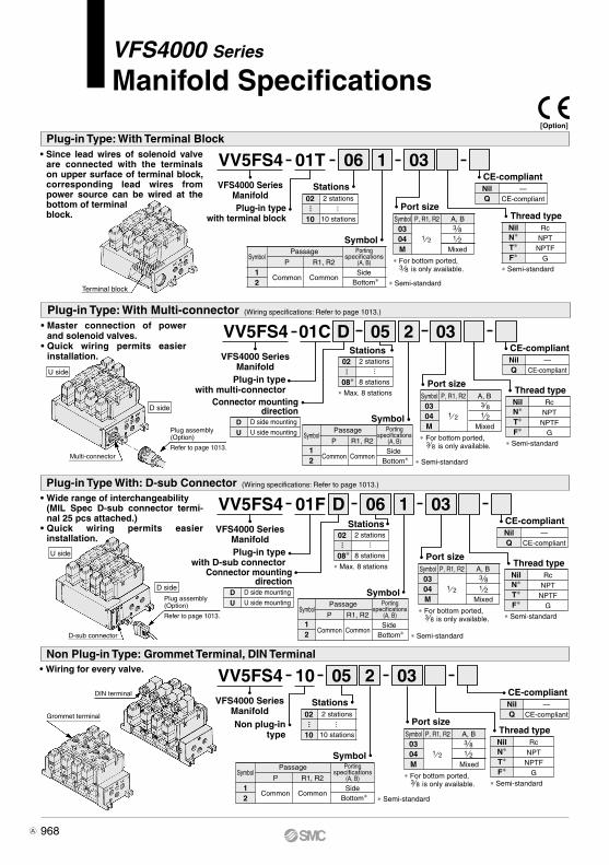
[Option]
Plug-in Type: With Terminal Block
Plug-in Type: With Multi-connector
Plug-in Type With: D-sub Connector
Non Plug-in Type: Grommet Terminal, DIN Terminal• Wiring for every valve.
01TVV5FS4
Plug-in typewith terminal block
Port sizeSymbol0304
A, BP, R1, R2
M
106 03VFS4000 Series
Manifold 02
10
Stations
Symbol
∗ Semi-standard
NilN∗
RcNPT
NPTFG
T∗F∗
∗ Semi-standard
Thread type
NilN∗
RcNPT
NPTFG
T∗F∗
∗ Semi-standard
Thread type
D01CVV5FS4
Plug-in typewith multi-connector
205 03VFS4000 Series
Manifold02
08∗
Stations
∗ Max. 8 stations
Q
CE-compliantNil —
CE-compliant
D01FVV5FS4
Plug-in typewith D-sub connector
106 03VFS4000 Series
Manifold
10VV5FS4
Non plug-in type
205 03VFS4000 Series
Manifold
• Since lead wires of solenoid valve are connected with the terminals on upper surface of terminal block, corresponding lead wires from power source can be wired at the bottom of terminal block.
• Master connection of power and solenoid valves.
• Quick wiring permits easier installation.
Mixed
2 stations
10 stations
1 21 2
3 8
Symbol
1 Side2
Passage
R1, R2P
CommonCommon
∗ For bottom ported, is only available.3 8
Port sizeSymbol0304
A, BP, R1, R2
M Mixed
1 21 2
3 8
∗ For bottom ported, is only available.3 8
NilN∗
RcNPT
NPTFG
T∗F∗
∗ Semi-standard
Thread type
Q
CE-compliantNil —
CE-compliant
Port sizeSymbol0304
A, BP, R1, R2
M Mixed
1 21 2
3 8
∗ For bottom ported, is only available.3 8
D side mounting
U side mountingDU
Connector mountingdirection
D side mounting
U side mountingDU
Connector mountingdirection
··· ···
2 stations
8 stations
···
···
02
08∗
Stations
∗ Max. 8 stations
2 stations
8 stations
···
···
Portingspecifications
(A, B)
Bottom∗
Port sizeSymbol0304
A, BP, R1, R2
M
02
10
Stations
Symbol
∗ Semi-standard
NilN∗
RcNPT
NPTFG
T∗F∗
∗ Semi-standard
Thread type
Q
CE-compliantNil —
CE-compliant
Mixed
2 stations
10 stations
1 21 2
3 8
Symbol
1 Side2
Passage
R1, R2P
CommonCommon
∗ For bottom ported, is only available.3 8
··· ···
Portingspecifications
(A, B)
Bottom∗
Symbol
∗ Semi-standard
Symbol
1 Side2
Passage
R1, R2P
CommonCommon
Portingspecifications
(A, B)
Bottom∗
Symbol
∗ Semi-standard
Symbol
1 Side2
Passage
R1, R2P
CommonCommon
Portingspecifications
(A, B)
Bottom∗
(Wiring specifications: Refer to page 1013.)
• Wide range of interchangeability(MIL Spec D-sub connector termi-nal 25 pcs attached.)
• Quick wiring permits easier installation.
(Wiring specifications: Refer to page 1013.)
Multi-connector
Plug assembly(Option)
Refer to page 1013.
Plug assembly(Option)
Refer to page 1013.
D-sub connector
DIN terminal
Grommet terminal
U side
U side
D side
D side
Terminal block
Q
CE-compliantNil —
CE-compliant
968
VFS4000 Series
Manifold Specifications
A

Manifold Specifications
Base model
Plug-in typeVV5FS4-01
Non plug-in typeVV5FS4-10
Wiring
• With terminal block• With multi-connector• With D-sub connector
• DIN terminal• Grommet terminal
A, B port
Side/Bottom
P, EA, EBPort size Rc
A, BStations
VFS40(R)-F(Z)
VFS41(R)-D(Z)VFS41(R)-E(Z)
How to Order Manifold Assembly
Note 1) With multi-connector, or with D-sub connector: 8 stations max.Note 2) It is possible to mount the standard valve and the external pilot type valve together.
Passage/Stations Station 1 Station 5 Station 1010.50.202.511
0.202.9
10.50.202.511
0.202.9
10.50.202.511
0.202.9
Model
VV5FS4
∗ Port size: Rc 1/2
<Example>• Plug-in type with terminal block: 6 stations (Manifold base) VV5FS4-01T-061-03 ······ 1 (2 position single) VFS4100-5FZ ············· 3 (2 position double) VFS4200-5FZ ············ 2 (Blanking plate) VVFS4000-10A ·············· 1
• Non plug-in type: 6 stations (Manifold base) VV5FS4-10-061-04 ········ 1 (2 position single) VFS4110-5D ··············· 5 (3 position exhaust center) VFS4410-5D ···· 1 (Individual EXH spacer) VVFS4000-R-04-2····· 1
Please indicate manifold base type, corresponding valve, and option parts.
Flow Rate Characteristics at the Number of Manifold Stations (Operated individually)
Portingspecifications Applicable
valve modelExternal
pilot
4/2 5/3(A/B R1/R2)
C [dm3/(s·bar)]
bCv
1 4/2(P A/B)
bC [dm3/(s·bar)]
Cv
, 1 2 1 23 8 2 to 10 Yes(1) (2)
(2)
969
VFS4000 Series5 Port Pilot Operated Solenoid Valve
Metal Seal, Plug-in/Non Plug-in
SV
SYJ
SZ
VF
VP4VQ1/2
VQ4/5
VQC1/2
VQC4/5
VQZ
SQ
VFS
VFR
VQ7
VFS

Manifold Option Parts Assembly Manifold Option
For details, refer to page 973.
For details, refer to page 975.
For details, refer to page 978.
Body type Plug-in typeVVFS4000-P-03-1
Non plug-in typeVVFS4000-P-03-2Part no.
Body type Plug-in typeVVFS4000-R-04-1
Non plug-in typeVVFS4000-R-04-2Part no.
Body type Plug-in typeAXT634-10A
Non plug-in typePart no.
Body type Plug-in typeAXT634-11A
Non plug-in typePart no.
EXH block plate SUP block plate
Body type Plug-in typeVVFS4000-20A-1
Non plug-in typeVVFS4000-20A-2Part no.
Part no.Body type Plug-in type
VVFS4000-22A-1Non plug-in typeVVFS4000-22A-2
Body type Plug-in typeARBF4050-00-P-1
Non plug-in typeARBF4050-00-P-2P port regulation
ARBF4050-00-A-1 ARBF4050-00-A-2A port regulationARBF4050-00-B-1 ARBF4050-00-B-2B port regulation
Body type Plug-in typeVVFS4000-10A
Non plug-in typePart no.
Individual SUP spacer An individual SUP spacer set on manifold block can form SUP port for every valve.
Individual EXH spacerAn individual EXH spacer set on manifold block can form EXH port for every valve.(common EXH type)
∗ SUP block plateWhen supplying manifold with more than two different pressures, high and low, insert a block plate in between stations subjected to Plug-in different pressures.
∗ EXH block plateWhen valve exhaust affects the other stations on the circuit or when a reverse pressure valve is used to a standard manifold valve, insert EXH block plate in between stations to separate valve exhaust.
Blanking plateIt is used by attaching on the manifold block for being prepared for removing a valve for maintenance reasons or planning to mount a spare valve, etc.
Throttle valve spacer Needle valve set on the manifold block can control cylinder speed by throttling exhaust.
With control unitPlug-in type/Non Plug-in type• Filter, regulation valve, pressure switch
and air release valve are all combined to form one unit.
• Piping processes are eliminated.
Double check spacerIf the double check spacer with a built-in double check valve is combined, it will enable the cylinder to stop in the intermediate stroke and maintain its position for a long time without being affected by the leakage between the spools.
With exhaust cleanerPlug-in type/Non Plug-in type• Valve exhaust noise dampening: 35 dB
or more.• Oil mist collection: Rate of collection
99.9% or more.• Piping process reduced.
Interface regulatorInterface regulator set on manifold block can regulate the pressure to each valve. (Refer to page 1011 for “Flow Rate Characteristics”.)
Made to OrderManifold with serial transmission kit Plug-in type• Solenoid valve wiring process reduced
considerably.
970
VFS4000 Series

Formula for manifold weight M = 0.565n + 0.923 (kg) n: Stations
Formula for manifold weight M = 0.478n + 0.671 (kg)Stations
L
L1
L2
2156168
3199211
4242254
5285297
6328340
7371383
8414426
9457469
10500512
FormulaL1 = 43 x n + 70L2 = 43 x n + 82
n: Stations
Manifold — Plug-in type, Non plug-in type
Plug-in type (With terminal block): VV5FS4-01T- Station 1- Port size
Non plug-in type: VV5FS4-10- Station 1- Port size
Bottom ported:VV5FS4-01T- Station 2- Port size
Bottom ported:VV5FS4-10- Station 2- Port size
Stations
Stations
Light
Light
Pilot valve manual override
Cable
(External pilot port)
Electrical entry
(Pilot EXH port: PE)
U side
D side
(Pilot EXH port: PE)
(External pilot port)
U side
D side
Pilot valve manual override
971
VFS4000 Series5 Port Pilot Operated Solenoid Valve
Metal Seal, Plug-in/Non Plug-in
SV
SYJ
SZ
VF
VP4VQ1/2
VQ4/5
VQC1/2
VQC4/5
VQZ
SQ
VFS
VFR
VQ7
VFS

Formula for manifold weight M = 0.57n + 1.011 (kg) n: Station∗ Wiring specifications: Refer to page 1013.
Formula for manifold weight M = 0.57n + 0.935 (kg)∗ Wiring specifications: Refer to page 1013.
StationsL
L1
L2
2156168
3199211
4242254
5285297
6328340
7371383
8414426
FormulaL1 = 43 x n + 70L2 = 43 x n + 82
Manifold — Plug-in type with multi-connector/D-sub connector
Plug-in type with D-sub connector: VV5FS4-01FD- Station 1- Port size , VV5FS4-01FU- Station 1- Port size
Plug-in type with multi-connector: VV5FS4-01CD- Station 1- Port size , VV5FS4-01CU- Station 1- Port size
Bottom ported:VV5FS4-01 - Station 2- Port sizeCD
CU
Bottom ported:VV5FS4-01 - Station 2- Port sizeFD
FU
n: Stations
U side
D side
U side
D side
Stations
Stations
Plug assembly VVFS2000-30A-(Option: Refer to page 1013.)
Plug assembly VVZS3000-21A-(Option: Refer to page 1013.)
(Pilot EXH port: PE)
(External pilot port)
Light
Light
Pilot valve manual override
Pilot valve manual override
(Pilot EXH port: PE)
(External pilot port)
972
VFS4000 Series

[Option]
Manifold Specifications
Plug-in type
Non plug-in type
CautionWhen using an exhaust cleaner, mount it downwards.
∗ Refer to Best Pneumatics No. 7 for Exhaust Cleaner details.
How to OrderExhaust cleaner(Option)
Note 1) With multi-connector, or with D-sub connector: 8 stations max. Note 2) Stations of 5 or more and high frequency of operation should be used with AMC810-14.
Exhaust cleaners AMC610-10 and AMC810-14 are not attached.
10610 03 CDVFS4000 Series
Manifold
VV5FS4
Base type/Electrical entry
01T
01C
01F
10
Symbol
CDCU
D sideU side
Exhaust Exhaust cleaner
mounting direction
D side mountingU side mounting
Exhaust cleanermounting direction
2 stations
10 stations
···
02
10
Stations
NilN∗
RcNPT
NPTFG
T∗F∗
Thread type
Port sizeSymbol
0304
A, BP
M
Exhaust cleaner(Option)
Manifold with Exhaust Cleaner
Manifold
Wiring
Applicable valve model
Porting specificationsRc
Stations
Plug-in type: VV5FS4-01 Non plug-in type: VV5FS4-10
With terminal blockWith multi-connectorWith D-sub connector
DIN terminal Grommet terminal
VFS400-F VFS410-D, VFS410-ECommon SUP/Common EXH
Side: 3/8, 1/2, Bottom: 3/8 (Option)P: 1/2, EXH: 1, 1 1/2
2 to 10 (1)
Applicable exhaust cleaners AMC610-10 (Connecting port size R 1), AMC810-14 (Connecting port size R 1 1/2) (2)
2(B), 4(A) port1(P), 3(R2), 5(R1) port
• Serves to protect working environment.
• Valve exhaust noise dampening: 35 dB or more.
• Collection rate of drainage and oil mist: 99.9% or more.
• Piping work is reduced.
Symbol
Plug-in typewith terminal block
Plug-in typewith multi-connector
Plug-in typewith D-sub connector
Non plug-in type
Symbol Applicable base
DNil
U01C, 01F
01T, 10With connector
D side mountingNone
U side mounting
Connector mounting direction
Base type 01T, 10: 2 to 10 stationsBase type 01C, 01F: 2 to 8 stations
<Example> • Plug-in type with terminal block (6 stations)
(Manifold base)(2 position single)(2 position double)(Blanking plate)(Exhaust cleaner)
• Non plug-in type (6 stations)
13211
VV5FS4-01T-061-03-CDVFS4100-5FZVFS4200-5FZVVFS4000-10AAMC610-10
(Manifold base)(2 position single)(2 position double)(Blanking plate)(Exhaust cleaner)
13211
VV5FS4-10-061-04-CUVFS4110-5EVFS4210-5EVVFS4000-10AAMC810-14
∗ Semi-standard ∗ Please indicate exhaust cleaner size or port size.
Q
CE-compliantNil —
CE-compliant
Mixed
1 21 2
3 8
∗ For bottom ported, is only available.3 8
···
Symbol
1 Side
2 Bottom∗
Passage
R1, R2P
CommonCommon
∗ Semi-standard
Portingspecifications
(A, B)
U side
D side
How to Order Manifold Assembly [Example]Add the valve and option part numbers in order starting from the first station on the D side.
∗ ∗ ∗
∗ ∗ ∗
The asterisk denotes the symbol for assembly. Prefix it to the part numbers of the solenoid valve.
973
VFS4000 Series5 Port Pilot Operated Solenoid Valve
Metal Seal, Plug-in/Non Plug-in
SV
SYJ
SZ
VF
VP4VQ1/2
VQ4/5
VQC1/2
VQC4/5
VQZ
SQ
VFS
VFR
VQ7
VFS
A

≈≈
≈≈
D side mounting
U side mounting
D side mounting
U side mounting
StationsL
L1
L2
2156168
3199211
4242254
5285297
6328340
7371383
8414426
9457469
10500512
FormulaL1 = 43 x n + 70L2 = 43 x n + 82
n: Stations
( ): AMC810
( ): AMC810
Manifold with Exhaust Cleaner — Plug-in type, Non plug-in type
Plug-in type: VV5FS4-01T- Station 1- Port size -CDCU
Non plug-in type: VV5FS4-10- Station 1- Port size - CDCU
Stations
Stations
Exhaust cleaner(Option)
Exhaust cleaner(Option)
Pilot valve manual override
Pilot valve manual override
(External pilot port)(Pilot EXH port: PE)
Manualoverride
Manualoverride
Electrical entry
(Pilot EXH port: PE)
U side
U side
D side
D side
U side
U side
D side
D side
1 2R1, 1
(External pilot port)
974
VFS4000 Series

[Option]
Manifold Specifications
Plug-in type
Non plug-in type
CautionWhen using an air filter with auto-drain or manual drain, mount the filter vertically.
How to Order
Note 1) With multi-connector, or with D-sub connector: 8 stations max.
VV5FS4 01C D 08 1 03 APVFS4000 Series
Manifold
Air release valve coil ratingNil1501T
01C01F10
Base type/Electrical entry
02
10∗
Stations
Manifold with Control Unit
Control Unit Specifications Control Unit/OptionAir filter (With auto-drain/With manual drain)Filtration degreeRegulatorSet pressure (Outlet pressure)Pressure switch (1)
Set pressure range: OFFDifferentialContact
Max. switch capacity
Max. operating current
Air release valve (Single only)Operating pressure range
5 µm
0.05 to 0.85 MPa
0.1 to 0.6 MPa
0.1 to 1.0 MPa
0.08 MPa or less1a
Indicator light LED (RED)2 VA AC, 2 W DC
24 VAC/DC or less: 50 mA48 VAC/DC: 40 mA100 VAC/DC: 20 mA
Air releasevalve spacer
Pressureswitch
Blankingplate
Filterelement
<Plug-in type>VVFS4000-24A-1R (D side mounting)<Non plug-in type>VVFS4000-24A-2R (D side mounting)
IS1000P-2-1Filter regulator
Pressure switchRelease valve
MP2-3MP3-2
VVFS4000-24A-1011104-5B
Note 1) Voltage: 24 VDC to 100 VACInner voltage drop: 4 V
Note 2) Combination of a valve VFS41 (single) and a release valve spacer can be used as an air release valve.
Note 3) The non plug-in type cannot be mounted afterwards.
Air filter with auto-drainControl equipment
Symbol
Air filter with manual drainRegulatorAir release valvePressure switchBlanking plate (Air release valve)Blanking plate (Filter, Regulator)Blanking plate (Pressure switch)
Number of manifold blocksrequired for mounting (stations)
A AP M MP F G C E
Control unit type
None (F, G type only)
100 VAC, 50/60 Hz24 VDC
Q
CE-compliantNil —
CE-compliant
Plug-in type with terminal blockPlug-in type with multi-connectorPlug-in type with D-sub connector
Non plug-in type
Symbol Applicable base
DNil
U01C, 01F
01T, 10With connector
D side mountingNone
U side mounting
Connector mounting direction
Port size
Thread type
∗ Base type 01T, 10: 2 to 10 stations
Base type 01C, 01F: 2 to 8 stations
Symbol A, BP, R1, R2
Mixed
1 21 2
3 8
RcNPT
NPTFG
Nil N∗ T∗ F∗
<Example>
(Manifold base)(2 position single)(2 position double)
• Non plug-in type: In order to mount control unit, it requires 2 stations.(Manifold base)(2 position single)
142
14
VV5FS4-01T-081-03-AP5VFS4100-5FZVFS4200-5FZ
VV5FS4-10-061-03-AVFS4110-5D
2 stations
10 stations
∗ For bottom ported, is only available.3 8
• Control unit (Filter, Regulator, Pres-sure switch, Air release valve) are all standardized to the one unit, and can be mounted on the mani-fold base without any attachments.
• Piping processes are eliminated.
··· ··· Symbol
Symbol
1 Side
2 Bottom∗
Passage
R1, R2P
CommonCommon
∗ Semi-standard
∗ Semi-standard
Portingspecifications
(A, B) 2 2 2 2 2 2 2 1
Nil
Manifold
Wiring
Applicable valve model
Porting specificationsRc (PT)
Stations
Plug-in type: VV5FS4-01 Non plug-in type: VV5FS4-10With terminal block
With multi-connectorWith D-sub connector
DIN terminal Grommet terminal
VFS400-F VFS410-D, VFS410-ECommon SUP, Common EXH
Side: 3/8, 1/2, Bottom: 3/8Side: 1/2
2 to 10 (1)
2(B), 4(A) port1(P), 3(R2), 5(R1) port
How to Order Manifold Assembly [Example]Add the valve and option part numbers in order starting from the first station on the D side.
∗ ∗
∗
The asterisk denotes the symbol for assembly. Prefix it to the part numbers of the solenoid valve.
• Plug-in type with terminal block: In order to mount control unit, it requires 2 stations.
(2)
(3)
0304M
For other rated voltages, please consult with SMC.
Regulator with filter
Manually operatedAuto-drain type
INA-13-864GINA-13-864DG
975
VFS4000 Series5 Port Pilot Operated Solenoid Valve
Metal Seal, Plug-in/Non Plug-in
SV
SYJ
SZ
VF
VP4VQ1/2
VQ4/5
VQC1/2
VQC4/5
VQZ
SQ
VFS
VFR
VQ7
VFS
B
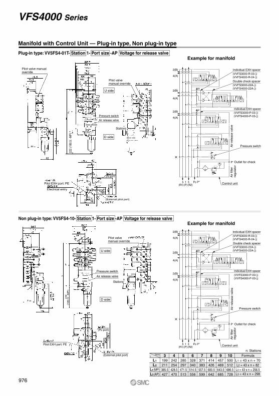
≈
≈
≈
≈
P
Pressure switch
P'
Individual EXH spacer
Double check spacer
Individual EXH spacer
P'
R'
2(B)
4(A)
2(B)
4(A)
2(B)
4(A)
X
P" Control unitPo3(R2)
1(P)
5(R1)
(VVFS3000-P-03-1 2)
(VVFS4000-P-03-1 2)
(VVFS3000-22A-1 2)
(VVFS4000-22A-1 2)
(VVFS3000-R-03-1 2)
(VVFS4000-R-04-1 2)
P
Pressure switch
P'
Individual EXH spacer
Double check spacer
Individual EXH spacer
P'
R'
2(B)
4(A)
2(B)
4(A)
2(B)
4(A)
X
P" Control unitPo3(R2)
1(P)
5(R1)
(VVFS3000-P-03-1 2)
(VVFS4000-P-03-1 2)
(VVFS3000-22A-1 2)
(VVFS4000-22A-1 2)
(VVFS3000-R-03-1 2)
(VVFS4000-R-04-1 2)
Example for manifold
Manifold with Control Unit — Plug-in type, Non plug-in type
Example for manifold
StationsL
L1
L2
L3 (MP)L3 (AP)
3199211
4242254
5285297
6328340
7371383
8414426
9457469
10500512
FormulaL1 = 43 x n + 70
n: Stations
L2 = 43 x n + 82385.5 428.5 471.5 514.5 557.5 600.5 643.5 686.5427 470 513 556 599 642 685 728
L3 = 43 x n + 256.5L3 = 43 x n + 298
Plug-in type: VV5FS4-01T- Station 1- Port size -AP Voltage for release valve
Non plug-in type: VV5FS4-10- Station 1- Port size -AP Voltage for release valve
Pilot valve manual override
Pilot valve manual override
Air
filte
rre
gula
tor
Outlet for check
Pressure switch
Air release valve
Pressure switch
Air release valve
Air
rele
ase
valv
eA
ir fil
ter
regu
lato
r
Outlet for check
Air
rele
ase
valv
e
Pilot valvemanual override
Stations
Stations
Pilot EXH port: PE
Electrical entry
(Po port)
(External pilot port)
U side
U side
D side
D side
222
(180
.5: -
MP
)(1
80.5
: -M
P)
Pilot EXH port: PE
(External pilot port)
(Po port)
976
VFS4000 Series

977
SV
SYJ
SZ
VF
VP4VQ1/2
VQ4/5
VQC1/2
VQC4/5
VQZ
SQ
VFS
VFR
VQ7
VFS

Refer to Best Pneumatics No. 1-1 and the Operation Manual for the details of EX123/124 Integrated-type (For Output) Serial Transmis-sion System. Please download the Operation Manual via our website, http://www.smcworld.com
VV5FS4 X19901S
Nil RcNPT
NPTFG
Thread type
NTF
Plug-in typeSerial transmission kit
Stations02
10
2 stations
10 stationsNote 1) Max. 10 stations. Add 1 station for serial unit mounting.Note 2) Max. 10 Stations: For single and double mixed wiring. (No. of
valves: 9) Max. 9 stations: For standard double wiring (No. of valves: 8)
Combination symbol
SymbolPort specification
P R1, R2
SideBottom
Pipingspecification
A, B
CommonCommon12∗
∗ Semi-standard
Port sizeSymbol
0304M
A, BP, R1, R2
1/2
∗ For bottom ported: 3/8 only
3/81/2
Mixed
SI unit mounting positionDU
D side mountingU side mounting
Applicable models
For U side mouning For D side mouning—
EX123U-SUH1EX124U-SDN1EX124U-SCS1EX124U-SCS2EX124U-SMJ1
—EX123D-SUH1EX124D-SDN1EX124D-SCS1EX124D-SCS2EX124D-SMJ1
DescriptionSI unit part no.
Without SI unitNKE Corporation: Fieldbus H System (16 outputs)DevieNet (2 power supply systems)OMRON Corporation: CompoBus/S (16 outputs) (2 power supply systems)OMRON Corporation: CompoBus/S (8 outputs) (2 power supply systems) CC-Link (2 power supply systems)
Symbol
0HQR1R2V
Correspondence of SI unit output numbers and solenoid valve coils<Wiring Example 1> Double wiring (Standard)
D side
Dou
ble
Dou
ble
Sin
gle
Sin
gle
Sin
gle
Dou
ble
Sin
gle
Sin
gle
SI u
nit
1
A B
2
A B
3
A B
4
A B
5
A B
6
A B
7
A B
8
A B
0 1 2 3 4 5 6 7 8 9 10 11 12 13 14 15
9
SI u
nit o
utpu
t no.
U side
<Wiring Example 2> Single/Double mixed wiring (Semi-standard)
∗ Mixed wiring is available as a semi-standard. Use the manifold specification sheet to specify this.
VFS4 00 5 F
24 VDC
Symbol123456
2 position single2 position double
3 position closed center3 position exhaust center3 position pressure center3 position double check
Nil Internal pilotExternal pilot
Pilot type
R
Nil Non-locking push type (Flush)Non-locking push type (Extended)
Locking type (Tool required)Locking type (Lever)
Pilot valve manual override
ABC
Nil NoneWith light/surge voltage suppressor
Option
Z
Nil NoneCoil rated voltage
D side
Dou
ble
Dou
ble
Sin
gle
Sin
gle
Sin
gle
Dou
ble
Sin
gle
Dou
ble
Sin
gle
SI u
nit
1
A B
2
A B
3
A
4
A
5
A
6
A B
7
A
8
A B
9
A
10
0 1 2 3 7 84 5 9 116
SI u
nit o
utpu
t no.
U side
10 11
How to Order Valves
How to Order Manifold
03108VU
Made to OrderSerial Transmission Kit Manifold: EX123/124 Integrated Type (For Output) Serial Transmission System
How to Order
SI unit can be mounted oneither U or D side.
978
VFS4000 Series
B

XE
AE
B
P
PE
SMC
A
SMC
A
SMC
A
SMC
A
SMC
A
SMC
B
SMC
B
SMC
B
SMC
BB
L2
L1
B
A
B
A
B
A
B
A
B
A
B
A
B
A
SMC
DimensionsFormula L1 = 43n + 70 L2 = 43n + 82
n: Stations (Max. 10 stations)
LL1
L2
n 2156168
3199211
4242254
5285297
6328340
7371383
8414426
9457469
10500512
Note) Actual number of manifold base stations: Add 1 SI unit mounting station to the number of valve stations.
1 2 3 4 5 6 7 nStationsD side U side
38
18
86
28 2424
23
63.5
42
1(P), 5(R3), 3(R1)6 x Rc 1/2
(Electrical entry)2 x G 1 1/4 (Pilot EXH port: PE)
2 x Rc 1/8
5.5
155.
5
95.5
187
202.
5166
105
55
47459
6
91.54319
6.5
205.
5
3043
33
62.5
141.
00
74.0
0
150.
5
115.
5
91.5
58
1814
3
Manual override
4(A), 2(B) port2n x Rc 3/8, 1/2
∗ Use a dripproof plug assembly (AXT100-B04A) for the unused conduit port (G 1/2).
SI unit
EX124: 4 x G 1/2
Electrical entry
EX123: 2 x G 1/2
Serial Transmission Kit Manifold (EX123/124): Plug-in Type
VV5FS4-01S Mounting position Model - Stations Symbol - Port size Thread -X199
979
VFS4000 Series5 Port Pilot Operated Solenoid Valve
Metal Seal, Plug-in/Non Plug-in
SV
SYJ
SZ
VF
VP4VQ1/2
VQ4/5
VQC1/2
VQC4/5
VQZ
SQ
VFS
VFR
VQ7
VFS

Manifold Option Parts — Plug-in type, Non plug-in type
( ): EXH block plate
Individual EXH spacer:VVFS4000-R-04-1 (Plug-in type)VVFS4000-R-04-2 (Non plug-in type)
SUP block plate: AXT634-10AEXH block plate: AXT634-11A
Throttle valve spacer:VVFS4000-20A-1 (Plug-in type) VVFS4000-20A-2 (Non plug-in type)
Interface regulator/A port regulation:ARBF4050-00-A-1 (Plug-in type)ARBF4050-00-A-2 (Non plug-in type)
Interface regulator/B port regulation:ARBF4050-00-B-1 (Plug-in type)ARBF4050-00-B-2 (Non plug-in type)
Interface regulator/P port regulation:ARBF4050-00-P-1 (Plug-in type)ARBF4050-00-P-2 (Non plug-in type)
Individual SUP spacer:VVFS4000-P-03-1 (Plug-in type)VVFS4000-P-03-2 (Non plug-in type)
Double check spacer:VVFS4000-22A-1 (Plug-in type)VVFS4000-22A-2 (Non plug-in type)
(172
: With
dire
ct m
anua
l ove
rrid
e)16
9
IndividualEXHspacer
(179
: With
dire
ct m
anua
l ove
rrid
e)
Interfaceregulator
(195
: With
dire
ct m
anua
l ove
rrid
e)
Interfaceregulator
Interfaceregulator
(195
: With
dire
ct m
anua
l ove
rrid
e)(1
95: W
ith d
irect
man
ual o
verr
ide)
(172
: With
dire
ct m
anua
l ove
rrid
e)
Block plate mounting position
Double checkspacer
Individual SUPspacer
Throttle valvespacer
980
VFS4000 Series

∗ D : For mounting the D side of the SI unit, U : For mounting the U side of the SI unit
12345678
9
13
10
11
12
Note) Manifold Base/Construction: Plug-in type with terminal block.
Manifold Base Construction — Plug-in type, Non Plug-in type
Replacement Parts: Sub Assembly
Replacement Parts
• For increasing the manifold bases, please order the manifold block assembly number of the principal part assembly !0.For plug-in type: The manifold base with terminal stand (integrated with a junction cover) is required with the o junction cover assembly.
No. DescriptionConnection fitting AConnection fitting BGasketGasketGasketO-ringO-ringTerminal assembly
Junction cover assembly
Rubber plug
MaterialSteel plateSteel plate
NBRNBRNBRNBRNBR—
For 01TFor 01S
NBR
Part no.VVF4000-5-1AVVF4000-5-2
VVF4000-7 (End plate)VVF4000-7-1 (Manifold block)
KA00407VVF4000-8
KA00078VVF4000-6A
VVF4000-4A- AZ738-30A-
AXT336-9
Stations
Stations
No. Description Assembly part no. Component parts Applicable manifold base
Manifold blockassembly
End plate (U side)assembly
End plate (D side)assembly
VVF4000-1A-1-
VVF4000-1A-2- VVF4000-2A-1VVF4000-2A-2
VVF4000-3A-1
VVF4000-3A-2
Manifold block !0, Terminal i, Metal joint q, w, Gasket r, Receptacle assembly
Manifold block !0, Metal joint q, w, Gasket rEnd plate (U) !1, Metal joint q, wEnd plate (U) !1, Metal joint q, w
End plate (D) !2, Metal joint q, w, Gasket e, t, O-ring y, u
End plate (D) !2, Metal joint q, w, Gasket e, t, O-ring t, y
Plug-in type
Plug-in type
Plug-in type
Non plug-in type
Non plug-in type
Non plug-in type
0304
0304
End plate (D side)
Manifold block
End plate (U side)
DU
981
VFS4000 Series5 Port Pilot Operated Solenoid Valve
Metal Seal, Plug-in/Non Plug-in
SV
SYJ
SZ
VF
VP4VQ1/2
VQ4/5
VQC1/2
VQC4/5
VQZ
SQ
VFS
VFR
VQ7
VFS
A

VFS5000 series is compatible with the old models, VF600 and VF610 series.
(A)4 2(B)
3(R2)
1(P)
5(R1)
3(R2)
5(R1)
1(P)
2(B)(A)4
(A)4 2(B)
3(R2)
1(P)
5(R1)
(A)4 2(B)
3(R2)
1(P)
5(R1)
(A)4 2(B)
3(R2)
1(P)
5(R1)
5(R1)
3(R2)
1(P)
(A)4 2(B)
Model
Symbol
Plug-in type
Non plug-in type
VFS5300
VFS5400
VFS5500
VFS5100
VFS5200
1516171516171416161416171416189.09.09.0
0.300.150.150.300.150.150.250.250.250.320.170.200.300.230.25———
0.300.150.130.300.150.130.240.240.230.250.180.130.310.220.22———
4.14.54.74.14.54.74.14.14.13.54.14.13.84.14.3———
3.73.73.93.73.73.94.04.14.13.83.84.23.73.94.6———
1519201519201416161416171416179.09.09.0
VFS5600
VFS5310
VFS5410
VFS5110
VFS5210
VFS5510
VFS5610
3 8
3 8
1 23 4
1 23 43 81 23 43 81 23 43 81 23 43 81 23 4
300
300
300
600
600
180
1.16
1.14
0.88
1.06
1.14
1.99
Note 1) Based on JIS B 8419: 2010 (once per 30 days) for the minimum operating frequency.Note 2) Based on JIS B 8419-2010. (The value at supply pressure 0.5 MPa, ambient/fluid
temperature (≈ 20°C))However, this excludes when in an adhered state. (Be aware that after long periods of holding time, there may be delays in the initial response time.)
Note 3) The figures in the above list are without sub-plate. In the case of with plug-in sub-plate and, with non plug-in sub-plate add Rc 3/8, 1/2—0.744 kg, Rc 3/4—0.966 kg and Rc 3/8, 1/2—0.577 kg, Rc 3/4—0.823 kg respectively.
Note 4) “Note 1) ” and “Note 2) ” are with controlled clean air.
Type of actuation
2 po
sitio
n3
posi
tion
Single
Double
Doublecheck
Closedcenter
Pressure center
Exhaust center
Model
Plug-in Non plug-in
PortsizeRc
C[dm3/(s·bar)] b Cv
C[dm3/(s·bar)] b Cv
1 4/2 (P A/B) 4/2 5/3 (A/B R1/R2) Flow rate characteristics
55 or less
55 or less
55 or less
45 or less
25 or less
60 or less
Compact yet provides a large flow capacity3/4: C: 20 dm3/(s·bar)
Low power consumption: 1.8 W DC
Easy maintenance2 types of sub-plates: Plug-in and non plug-in
Option Specifications
Standard SpecificationsFluidMaximum operating pressureMinimum operating pressureProof pressureAmbient and fluid temperatureLubricationPilot valve manual overrideImpact/Vibration resistance
Enclosure
Coil rated voltageAllowable voltage fluctuationCoil insulation typeApparent power(Power consumption)
Power consumption DC
InrushHolding
Electrical entry
Val
ve s
pec
ific
atio
ns
Elec
tric
ity s
peci
ficat
ions
Air
1.5 MPa–10 to 60°C (1)
Non-lube (2)
Non-locking push type (Flush)150/50 m/s2 (3)
Type E: Dustproof (Equivalent to IP50), Type F: Dripproof (Equivalent to IP52), Type D: Splashproof (Equivalent to IP54) (4) (6)
100, 200 VAC, 50/60 Hz; 24 VDC–15 to +10% of rated voltage
Class B or equivalent (130°C) (5)
5.6 VA/50 Hz, 5.0 VA/60 Hz3.4 VA (2.1 W)/50 Hz, 2.3 VA (1.5 W)/60 Hz
1.8 W (2.04 W: With light/surge voltage suppressor)Plug-in type
Non plug-in type
1.0 MPa0.1 MPa
Note 1) Use dry air at low temperatures. Note 2) Use turbine oil Class 1 (ISO VG32), if lubricated.Note 3) Impact resistance: No malfunction occurred when it is tested with a drop tester in the axial direction
and at the right angles to the main valve and armature in both energized and de-energized states every once for each condition. (Values at the initial period)
Vibration resistance: No malfunction occurred in a one-sweep test between 45 and 2000 Hz. Test was performed at both energized and de-energized states in the axial direction and at the right angles to the main valve and armature. (Values at the initial period)
Note 4) Based on JIS C 0920. Note 5) Based on JIS C 4003.Note 6) The F type enclosure described above shows that without the light/surge voltage suppressor. The F
type enclosure with the light/surge voltage suppressor is equivalent to IP50.
AC
Conduit terminalGrommet terminal, DIN terminal
Pilot type
Manualoverride
Main valvePilot valve
Coil rated voltage
Porting specificationsOption
External pilot Note)
Direct manual overrideNon-locking push type (Extended), Locking type (Tool required), Locking type (Lever)
110 to 120, 220, 240 VAC (50/60 Hz) 12, 100 VDC
Bottom portedWith light/surge voltage suppressor, Non-rotating DIN terminal
Note) Operating pressure: 0 to 1.0 MPa Pilot pressure: 0.1 to 1.0 MPa
2 positionSingle
Double
3 positionClosed center
Exhaust center
Pressure center
Double check
Max. operating
cycle(cpm)
(Details → P. 1007)
Responsetime(ms)
Weight(kg)
(1)(2) (3)
[Option]
982
5 Port Pilot Operated Solenoid ValveMetal Seal, Plug-in/Non Plug-in
VFS5000 Series
A

[Option]
(A)4 2(B)
3(R2)
1(P)
5(R1)
(A)4 2(B)
3(R2)
1(P)
5(R1)
(A)4 2(B)
3(R2)
1(P)
5(R1)
3(R2)
5(R1)
1(P)
2(B)(A)4
(A)4 2(B)
3(R2)
1(P)
5(R1)
5(R1)
3(R2)
1(P)
(A)4 2(B)
How to Order Pilot Valve Assembly
1 04FVFS5 2
DVFS5
Symbol
1
2 position single
2
2 position double
3
3 position closed center
4
3 position exhaust center
5
3 position pressure center
6
3 position double check
O: Plug-in type sub-plate
1: Non plug-in type sub-plate
Body type
Pilot valveManual override
Port sizeNil0304
Thread typeNilN∗ NPT
Rc
T∗ NPTFF∗ G
∗ Semi-standard
06
Pilot typeNilR∗
Internal pilotExternal pilot
∗ Semi-standard
Body option01∗
StandardDirect manual override
∗ Semi-standard
Coil rated voltage
∗ Semi-standard
Nil: Non-locking push type(Flush)
06
0
1
0
5
Body type
OptionNilZP∗
ZP∗
A∗: Non-locking push type(Extended)
B∗: Locking type (Tool required)
C∗: Locking type(Lever)
F: Plug-in typeconduit terminal
Electrical entry
1 0
∗ Semi-standardFor other rated voltages, please consult with SMC.∗∗ Refer to page 1010 for voltage conversion.
Manual override Coil rated voltage
SF4 F1 30
How to Order
Portingspecifications
NilB∗
Plug-in
Non plug-in
Side portedBottom ported
Without sub-plate3 81 23 4
123∗4∗56∗7∗
100 VAC, 50/60 Hz200 VAC, 50/60 Hz
110 to 120 VAC, 50/60 Hz220 VAC, 50/60 Hz
24 VDC12 VDC
240 VAC, 50/60 Hz
NoneWith light/surge voltage suppressor
Q
CE-compliantNil —
CE-compliant
Non-rotating DIN terminal
Light/Surge Voltage SuppressorNon-rotating DIN terminal
E: Grommet terminal D: DIN terminalDO: DIN terminal
without connector
Electrical entry
∗ In the case of external pilot (Semi-standard), bottom piping is not available.
∗ Type “P”, “ZP” is available for DIN type only.
1 100 VAC, 50/60 Hz2 200 VAC, 50/60 Hz3∗ 110 to 120 VAC, 50/60 Hz4∗ 220 VAC, 50/60 Hz5 24 VDC6∗ 12 VDC7∗ 240 VAC, 50/60 Hz
∗ Semi-standard
Nil
B∗
A∗
Non-locking push type(Flush)
Non-locking push type(Extended)
Locking type (Tool required)
C∗ Locking type (Lever)
∗ Semi-standardFor other rated voltages, please consult with SMC.
983
VFS5000 Series5 Port Pilot Operated Solenoid Valve
Metal Seal, Plug-in/Non Plug-in
SV
SYJ
SZ
VF
VP4VQ1/2
VQ4/5
VQC1/2
VQC4/5
VQZ
SQ
VFS
VFR
VQ7
VFS
A

Cylinder Speed Chart
Plug-in type
Specifications Check Valve Operation
Non plug-in type
Caution
Double check spacer
Series
VFS5100-06
800700600500400300200100 0
Bore size
ø125 ø140 ø160 ø180 ø200 ø250 ø300
CS1 seriesSGP20A x 1 m
AS500-06AN500-06
Tube bore x LengthSpeed controllerSilencer
VFS5100-06
Conditions
VVFS5000-22A-1 VVFS5000-22A-2
Double Check Spacer/Specifications
Can hold an intermediate cylinder position for an extended timeIf the double check spacer with a built-in double check valve is combined, it will enable the cylinder to stop in the intermediate stroke and maintain its position for a long time without being affected by the leakage between the spools.
• In the case of 3 position double check valve (VFS560), check the leakage from piping and fittings in between valve and cylinder by means of synthetic detergent solutions, and ensure that there is no such leakage found there. Also check the leakage from cylinder seal and piston seal. If there is any leakage, sometimes the cylinder, when valve is de-energized, can move without stopping at intermediate position.
• Be aware that if the exhaust side is restricted excessively, the intermediate stopping accuracy will decrease and will lead to improper intermediate stops.
• The combination of VFS51 0, VFS52 0 and a double check spacer can be used as prevention of falling at the stroke end but cannot hold the intermediate position of the cylinder.
CS1/CS2 seriesPressure 0.5 MPaLoad factor 50%Stroke 300 mm
∗ It is when the cylinder is extending that is meter-out controlled by speed controller which is directly connected with cylinder, and its needle valve with being fully open.
∗ The average velocity of the cylinder is what the stroke is divided by the total stroke time.∗ Load factor: ((Load mass x 9.8)/Theoretical force) x 100%
Use as a guide for selection.Please confirm the actual conditions with SMC Sizing Program.
Averagespeed(mm/s)
Perpendicular,upward actuationHorizontalactuation
01
01
Check valve
Piston SUP side pressure (P1)
Operating range
Cylinder side pressure P2 (MPa)
Cylinder side pressure(P2)
SU
P s
ide
pres
sure
P1
(MP
a)
Double checkspacer part no.
Applicablevalve model
Plug-in type
VFS5400-F
Non plug-in type
VFS5410-DVFS5410-E
984
VFS5000 Series

(A)4 2(B)
3(R2)
1(P)
5(R1)
(A)4 2(B)
3(R2)
1(P)
5(R1)
(A)4 2(B)
3(R2)
1(P)
5(R1)
3(R2)
5(R1)
1(P)
2(B)(A)4
5(R1)
3(R2)
1(P)
(A)4 2(B)
Construction
Sub-plate Assembly Part No.
∗ Mounting bolt and gasket are not included.
Plug-in
Non plug-in
VFS5000-P- (N, T, F)
VFS5000-S- (N, T, F)
030406030406
Sub-plate Assembly (For External Pilot) Part No.
Plug-in VFS5000-P-R (N, T, F)
VFS5000-S-R (N, T, F)
030406030406
Component PartsNo.
23
1Description Note
4—
56 —7 —8 —9 —10 —11 —12 — —13 — —
∗ Refer to “How to Order Pilot Valve Assembly” on page 983.
2 position single 2 position double
3 position closed center/exhaust center/pressure center
Closed center
Exhaust center
Pressure center
Aluminum die-castedStainless steel
MaterialAluminum die-casted —
—
——
Sub-plateBody
Spool/SleeveAdapter plateEnd plate
ResinPistonResin
ResinResin
Junction coverResinLight cover
Return springGasket
Pilot valve assembly
Stainless steelNBR
Hexagon socket head screw SteelDetent assembly
Note) When ordering the parts shown above for the replacement, note that the described date may slightly vary depending on the product being used.
Note
BG-VFS5000-1
BG-VFS5000
Groove gasket type(After September 2012) Note)
Plate gasket type(Earlier than August, 2012) Note)
Part no. for mounting bolt and gasket
985
VFS5000 Series5 Port Pilot Operated Solenoid Valve
Metal Seal, Plug-in/Non Plug-in
SV
SYJ
SZ
VF
VP4VQ1/2
VQ4/5
VQC1/2
VQC4/5
VQZ
SQ
VFS
VFR
VQ7
VFS
A

Plug-in — 2 Position single/Double/3 Position closed center/Exhaust center/Pressure center/Double check
3 position double check: VFS5600-F(Z)
2 position single: VFS5100-F(Z)
2 position double: VFS5200-F(Z)3 position closed center: VFS5300-F(Z)3 position exhaust center: VFS5400-F(Z)3 position pressure center: VFS5500-F(Z)
3 4( ): Rc
3 4( ): Rc 3 4( ): Rc
2 x ø7mounting hole
2 x ø7 mountinghole
2 x ø7 mountinghole
Bottom ported
3(R2), 5(R1): Rc 1/2
With light/surgevoltage suppressor
With light/surgevoltage suppressor
With light/surgevoltage suppressor
Pilot valvemanual override
Direct manual override
G 1/2 electrical entry
Pilot valvemanual override
Direct manual override
G 1/2electrical entry
Pilot valvemanual override
Direct manual override
G 1/2electrical entry
Rc 1/8 external pilot(Port size: Rc 3/8, 1/2)
(Pilot EXH port)Rc 1/8 external pilot(Port size: Rc 3/4)
219.3 (218) 3 position 227.3 (226)
2(B
), 4
(A)
port
986
VFS5000 Series

Description Part no.
UKL-S1DXT087-27-2
ConnectorGasket
DIN Connector/Gasket Part No.
Non Plug-in — 2 Position single/Double/3 Position closed center/Exhaust center/Pressure center/Double check
2 position double: VFS5210-E(Z), VFS5210-D(Z)3 position closed center: VFS5310-E(Z), VFS5310-D(Z)3 position exhaust center: VFS5410-E(Z), VFS5410-D(Z)3 position pressure center: VFS5510-E(Z), VFS5510-D(Z)
3 position double check: VFS5610-E(Z), VFS5610-D(Z)
2 position single: VFS5110-E(Z), VFS5110-D(Z)
( ): Rc 3/4
( ): Rc 3/4 ( ): Rc 3/4
2 x ø7 mountinghole
2 x ø7 mountinghole
Rc 3/4: 3(R2), Rc 1/2: 5(R1)
Applicable cabtire cable O.D.ø8 to ø10
Pilot valvemanual override
Direct manual override
Applicable cabtire cable O.D.ø8 to ø10
Pilot valvemanual override
Direct manualoverride
Applicable cabtire cable O.D.ø8 to ø10
Pilot valvemanual override
Direct manualoverride
101.5 (3 position: 109.5)
Rc 1/8external pilot(Port size Rc 3/8, 1/2)
Rc 1/8 external pilot(Port size: Rc 3/4)
2(B
), 4
(A)
port
G 1 2
2 x ø7 mounting hole
2 x Rc 1/8(Pilot EXH port)
987
VFS5000 Series5 Port Pilot Operated Solenoid Valve
Metal Seal, Plug-in/Non Plug-in
SV
SYJ
SZ
VF
VP4VQ1/2
VQ4/5
VQC1/2
VQC4/5
VQZ
SQ
VFS
VFR
VQ7
VFS

[Option]
∗ For bottom ported, is only available.
∗ For bottom ported, is only available.
∗ For bottom ported, is only available.
NilN∗
RcNPT
NPTFG
T∗F∗
∗ Semi-standard
Thread type
Q
CE-compliantNil —
CE-compliant
Port sizeSymbol
0406
A, BP, R1, R2
M Mixed
1 2
3 43 4
1 2
∗ For bottom ported, is only available.
NilN∗
RcNPT
NPTFG
T∗F∗
∗ Semi-standard
Thread type
Q
CE-compliantNil —
CE-compliant
Port sizeSymbol
0406
A, BP, R1, R2
M Mixed
1 2
3 43 4
1 2
Plug-in Type: With Terminal Block
Plug-in Type: With Multi-connector
Plug-in Type: With D-sub Connector
Non Plug-in Type: Grommet Terminal, DIN Terminal
01TVV5FS5
Plug-in typewith terminal block Port size
Symbol
0406
A, BP, R1, R2
M Mixed
106 04VFS5000 Series
Manifold
···
2 stations
10 stations
···
02
10
Stations
NilN∗
RcNPT
NPTFG
T∗F∗
∗ Semi-standard
Thread type
NilN∗
RcNPT
NPTFG
T∗F∗
∗ Semi-standard
Thread type
D
Connector mounting
direction
01CVV5FS5
Plug-in typewith multi-connector
205 04VFS5000 Series
Manifold Q
CE-compliantNil —
CE-compliant
D01FVV5FS5
Plug-in typewith D-sub connector
106 04VFS5000 Series
Manifold
10VV5FS5
Non plug-in type
205 04VFS5000 Series
Manifold
• Since lead wires of solenoid valve are connected with the terminals on upper surface of terminal block, corresponding lead wires from power source can be wired at the bottom of terminal
block.
• Master connection of power and solenoid valves.
• Quick wiring permits easier installation.
• Wide range of interchangeability(MIL Spec. D-sub connector terminal 25 pcs attached.)
• Quick wiring permits easier installation.
• Wiring for every valve.
1 2
Stations
Symbol
∗ Max. 8 stations
(Wiring specifications: Refer to page 1013.)
(Wiring specifications: Refer to page 1013.)
∗ Semi-standard
3 43 4
1 2
Q
CE-compliantNil —
CE-compliant
Port sizeSymbol
0406
A, BP, R1, R2
M Mixed
1 2
3 43 4
1 2
2 stations
8 stations
···
Stations02
10
···
2 stations
10 stations
···
∗ Semi-standard
Symbol
1 Side2
Passage
R1, R2P
CommonCommon
Portingspecifications
(A, B)
Bottom∗
Symbol
∗ Semi-standard
Symbol
1 Side2
Passage
R1, R2P
CommonCommon
Portingspecifications
(A, B)
Bottom∗
Symbol
Symbol
1 Side2
Passage
R1, R2P
CommonCommon
Portingspecifications
(A, B)
Bottom∗
∗ Semi-standard
Symbol
Symbol
1 Side2
Passage
R1, R2P
CommonCommon
Portingspecifications
(A, B)
Bottom∗
U side
U side
D side
D side
Multi-connector
D-sub connector
DIN terminal
Grommet terminal
Plug assembly(Option)
Refer to page 1013.
Plug assembly(Option)
Refer to page 1013.
02
08∗
···
Stations
∗ Max. 8 stations
2 stations
8 stations
···
02
08∗
···
D side mounting
U side mountingDU
Connector mounting
directionD side mounting
U side mountingDU
988
VFS5000 Series
Manifold Specifications
A

Base model
Plug-in typeVV5FS5-01
Non plug-in typeVV5FS5-10
Wiring
• With terminal block• With multi-connector• With D-sub connector
• DIN terminal• Grommet terminal
A, B port
Side/Bottom
P, EA, EB
3 4 ,1 2 3 4
Port size RcA, B
Stations
2 to 10 Yes(1) (2)
(2)Applicablevalve model
Externalpilot
VFS50(R)-F(Z)
VFS51(R)-D(Z)VFS51(R)-(E)
Manifold Option Parts Assembly Manifold Option
For details, refer to page 994.
For details, refer to page 992.
Individual SUP spacer An individual SUP spacer set on manifold block can form SUP port for every valve.
Manifold Specifications
Flow Rate Characteristics at the Number of Manifold Stations (Operated individually)
Individual EXH spacerAn individual EXH spacer set on manifold block can form EXH port for every valve. (common EXH type)
SUP block plateWhen supplying manifold with more than two different pressures, high and low, insert a block plate in between stations subjected to different pressures.
EXH block plateWhen valve exhaust affects the other stations on the circuit or when a reverse pressure valve is used on a standard manifold valve, insert EXH block plate in between stations to separate valve exhaust.
Blanking plate It is used by attaching on the manifold block for being prepared for removing a valve for maintenance reasons or planning to mount a spare valve, etc.
Double check spacerIf the double check spacer with a built-in double check valve is combined, it will enable the cylinder to stop in the intermediate stroke and maintain its position for a long time without being affected by the leakage between the spools.
Throttle valve spacer Needle valve set on the manifold block can control cylinder speed by throttling exhaust.
EXH block plate SUP block plate
Note 1) With multi-connector, or with D-sub connector: 8 stations max.Note 2) It is possible to mount the standard valve and the external pilot type valve together.
∗ Port size: Rc 1/2, 3/4
4/2 5/3(A/B R1/R2)
C [dm3/(s·bar)]b
Cv
Passage/Stations
1 4/2(P A/B)
Station 1 Station 5 Station 10
bC [dm3/(s·bar)] 15.0
0.204.016.00.204.2
15.00.204.016.00.204.2
15.00.204.016.00.204.2
Cv
Model
VV5FS5
Body type Plug-in typeVVFS5000-P-04-1
Non plug-in typeVVFS5000-P-04-2Part no.
Body type Plug-in type
VVFS5000-20A-1
Non plug-in type
VVFS5000-20A-2Part no.
Body type Plug-in typeVVFS5000-R-04-1
Non plug-in typeVVFS5000-R-04-2Part no.
Body type Plug-in type
VVFS5000-22A-1
Non plug-in type
VVFS5000-22A-2Part no.
Body type Plug-in typeAXT628-12A
Non plug-in typePart no. Body type Plug-in type
ARBF5050-00-P-1Non plug-in typeARBF5050-00-P-2P port regulation
ARBF5050-00-A-1 ARBF5050-00-A-2A port regulationARBF5050-00-B-1 ARBF5050-00-B-2B port regulation
Body type Plug-in typeAXT512-14-1A
Non plug-in typePart no.
Body type Plug-in typeVVFS5000-10A
Non plug-in typePart no.
<Example>• Plug-in type with terminal block: 6 stations (Manifold base) VV5FS5-01T-061-04 ······ 1 (2 position single) VFS5100-5FZ ··········· 3 (2 position double) VFS5200-5FZ ·········· 2 (Blanking plate) VVFS5000-10A ············· 1
• Non plug-in type: 6 stations (Manifold base) VV5FS5-10-061-04 ········ 1 (2 position single) VFS5110-5D ············· 5 (3 position exhaust center) VFS5410-5D ········ 1 (Individual EXH center) VVFS5000-R-04-2 ···· 1
How to Order Manifold AssemblyPlease indicate manifold base type, corresponding valve, and option parts.
With exhaust cleanerPlug-in type/Non plug-in type• Valve exhaust noise dampening: 35 dB
or more.• Oil mist collection: Rate of collection
99.9% or more.• Piping process reduced.
Interface regulatorInterface regulator set on manifold block can regulate the pressure to each valve. (In the event of using, refer to “Flow Rate Characteristics” on page 1011).
Made to OrderManifold with serial transmission kit Plug-in type• Solenoid valve wiring process reduced
considerably.
Portingspecifications
989
VFS5000 Series5 Port Pilot Operated Solenoid Valve
Metal Seal, Plug-in/Non Plug-in
SV
SYJ
SZ
VF
VP4VQ1/2
VQ4/5
VQC1/2
VQC4/5
VQZ
SQ
VFS
VFR
VQ7
VFS

Formula for manifold weight M = 0.811n + 1.231 (kg) n: StationStations
L
L1
L2
2194212
3245263
4296314
5347365
6398416
7449467
8500518
9551569
10602620
FormulaL1 = 51 x n + 92L2 = 51 x n + 110
Manifold — Plug-in type, Non plug-in type
Non plug-in type: VV5FS5-10- Station 1- Port size
Formula for manifold weight M = 0.911n + 1.621 (kg) n: Station3 4( ): 2(B)/4(A) port Rc
3 4( ): 2(B)/4(A) port Rc
Plug-in type (With terminal block): VV5FS5-01T- Station 1- Port size
Bottom ported:VV5FS5-01T- Station 2- Port size
DIN terminalVV5FS5-10- Station 2- Port size
Direct manual override
Pilot valvemanual override
Direct manual override
Pilot valvemanual override
Applicable cabtire cable O.D.ø8 to ø10
Stations
Pitc
hP
= 5
1P
itch
P =
51
Stations
Electrical entry
(External pilot)
(Pilot EXH)
U side
U side
D side
D side
(External pilot)
(Pilot EXH)
(External pilot)
(Pilot EXH)
990
VFS5000 Series
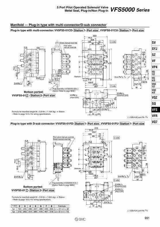
StationsL
L1
L2
2194212
3245263
4296314
5347365
6398416
7449467
8500518
FormulaL1 = 51 x n + 92L2 = 51 x n + 110
Manifold — Plug-in type with multi-connector/D-sub connector
Plug-in type with multi-connector: VV5FS5-01CD- Station 1- Port size , VV5FS5-01CU- Station 1- Port size
Plug-in type with D-sub connector: VV5FS5-01FD- Station 1- Port size , VV5FS5-01FU- Station 1- Port size
Bottom ported: VV5FS5-01 - Station 2- Port sizeCD
CU
Formula for manifold weight M = 0.916n + 1.709 (kg) n: Station ∗ Refer to page 1013. For wiring specifications.
Bottom ported:VV5FS5-01 - Station 2- Port sizeFD
FU
Formula for manifold weight M = 0.916n + 1.633 (kg) n: Station ∗ Refer to page 1013. For wiring specifications.
U side
D side
U side
D side
Direct manual override
Pilot valvemanual override
Plug assembly VVFS2000-30A-(Option: Refer to page 1013.)
Pilot valve manual overrideDirect manual override
Plug assembly VVZS3000-21A-(Option: Refer to page 1013.)
Stations
Stations
(External pilot)
(External pilot)
Pitc
hP
= 5
1P
itch
P =
51
( ): 2(B)/4(A) port Rc 3 4
( ): 2(B)/4(A) port Rc 3 4
(Pilot EXH)
(Pilot EXH)
991
VFS5000 Series5 Port Pilot Operated Solenoid Valve
Metal Seal, Plug-in/Non Plug-in
SV
SYJ
SZ
VF
VP4VQ1/2
VQ4/5
VQC1/2
VQC4/5
VQZ
SQ
VFS
VFR
VQ7
VFS

[Option]
Manifold Specifications
Manifold with Exhaust Cleaner
Plug-in type
Non plug-in type
CautionWhen using an exhaust cleaner, mount it downwards.
∗ Refer to Best Pneumatics No. 7 for Exhaust Cleaner details.
How to Order
Exhaust cleaner(Option)
Exhaust cleaner(Option)
10610 04 CDVFS5000 Series
Manifold
VV5FS5
Base type/Electrical entry
01T
01C
01F
10
Symbol
CDCU
D sideU side
Exhaust cleanermounting direction
D side mountingU side mounting
Exhaust cleanermounting direction
∗ Semi-standard
Thread type
Port sizeSymbol0406
A, BP
M
• Serves to protect working environment.
• Valve exhaust noise dampening: 35 dB or more.
• Collection rate of drainage and oil mist: 99.9% or more.
• Piping work is reduced.
Connector mounting direction
Stations
Manifold
Wiring
Applicable valve model
Porting specificationsRc
Stations
Plug-in type: VV5FS5-01 Non plug-in type: VV5FS5-10
With terminal blocksWith multi-connectorWith D-sub connector
DIN terminal Grommet terminal
VFS500-F VFS510-D, VFS510-ECommon SUP/Common EXH
Side: 1/2, 3/4, Bottom: 1/2 (Option)
2 to 10 (1)
Applicable exhaust cleaners AMC810-14 (Connecting port size R 1 1/2) (2)
P: 3/4, EXH: 1 1/2
Note 1) With multi-connector, or with D-sub connector: 8 stations max.Note 2) Exhaust cleaner: Not attached.
2(B), 4(A) port1(P), 3(R2), 5(R1)
U side
D side
∗ For bottom ported, is only available.
Symbol
VV5FS5-10-061-04-CUVFS5110-5EVFS5210-5EVVFS5000-10AAMC810-14
Plug-in typewith terminal block
Plug-in typewith multi-connector
Plug-in typewith D-sub connector
Non plug-in type
Symbol Applicable base
DNil
U01C, 01F
01T, 10With connector
D side mountingNone
U side mounting
2 stations
10 stations
02
10Base type 01T, 10: 2 to 10 stationsBase type 01C, 01F: 2 to 8 stations
··· ···
NilN∗
RcNPT
NPTFG
T∗
F∗
Mixed
3 43 4
1 2
1 2
Symbol
1 Side
2 Bottom∗
Passage
R1, R2P
CommonCommon
∗ Semi-standard
Portingspecifications
(A, B)
<Example> • Plug-in type with terminal block (6 stations)
(Manifold base)(2 position single)(2 position double)(Blanking plate)(Exhaust cleaner)
• Non plug-in type (6 stations)
13211
VV5FS5-01T-061-04-CDVFS5100-5FZVFS5200-5FZVVFS5000-10AAMC810-14
(Manifold base)(2 position single)(2 position double)(Blanking plate)(Exhaust cleaner)
13211
How to Order Manifold Assembly [Example]Add the valve and option part numbers in order starting from the first station on the D side.
∗ ∗ ∗
∗ ∗ ∗
The asterisk denotes the symbol for assembly. Prefix it to the part numbers of the solenoid valve.
Q
CE-compliantNil —
CE-compliant
992
VFS5000 Series
A

Manifold with Exhaust Cleaner — Plug-in type, Non plug-in type
D side mounting
U side mounting
D side mounting
U side mounting
StationsL
L1
L2
2194212
3245263
4296314
5347365
6398416
7449467
8500518
9551569
10602620
FormulaL1 = 51 x n + 92L2 = 51 x n + 110
n: Stations
Plug-in type: VV5FS5-01T- Station 1- Port size -CDCU
Non plug-in type: VV5FS5-10- Station 1- Port size - CDCU
( ): 2(B)/4(A) port Rc 3/4
( ): 2(B)/4(A) port Rc 3/4
Direct manualoverride
Pilot valvemanual override
≈
Direct manualoverride
Pilot valvemanual override
Stations
Stations
Electrical entry
Exhaust cleaner(Option)
U side
U side
D side
U side
D side
D side
U side
D side
Exhaust cleaner(Option)
≈≈
993
VFS5000 Series5 Port Pilot Operated Solenoid Valve
Metal Seal, Plug-in/Non Plug-in
SV
SYJ
SZ
VF
VP4VQ1/2
VQ4/5
VQC1/2
VQC4/5
VQZ
SQ
VFS
VFR
VQ7
VFS

Refer to Best Pneumatics No. 1-1 and the Operation Manual for the details of EX123/124 Integrated-type (For Output) Serial Transmis-sion System. Please download the Operation Manual via our website, http://www.smcworld.com
VV5FS5 X19901SPlug-in type
Serial transmission kit
Stations02
10
2 stations
10 stationsNote 1) Max. 10 stations. Add 1 station for serial unit mounting.Note 2) Max. 10 Stations: For single and double mixed wiring. (No. of
valves: 9) Max. 9 stations: For standard double wiring (No. of valves: 8)
Port sizeSymbol
0406M
A, BP, R1, R2
3/4
∗ For bottom ported: 1/2 only
1/23/4
Mixed
SI unit mounting positionDU
D side mountingU side mounting
Applicable models
For U side mouning For D side mouning—
EX123U-SUH1EX124U-SDN1EX124U-SCS1EX124U-SCS2EX124U-SMJ1
—EX123D-SUH1EX124D-SDN1EX124D-SCS1EX124D-SCS2EX124D-SMJ1
DescriptionSI unit part no.
Without SI unitNKE Corporation: Fieldbus H System (16 outputs)DevieNet (2 power supply systems)OMRON Corporation: CompoBus/S (16 outputs) (2 power supply systems)OMRON Corporation: CompoBus/S (8 outputs) (2 power supply systems) CC-Link (2 power supply systems)
Symbol
0HQR1R2V
Correspondence of SI unit output numbers and solenoid valve coils<Wiring Example 1> Double wiring (Standard)
D side
Dou
ble
Dou
ble
Sin
gle
Sin
gle
Sin
gle
Dou
ble
Sin
gle
Sin
gle
SI u
nit
1
A B
2
A B
3
A B
4
A B
5
A B
6
A B
7
A B
8
A B
0 1 2 3 4 5 6 7 8 9 10 11 12 13 14 15
9
SI u
nit o
utpu
t no.
U side
<Wiring Example 2> Single/Double mixed wiring (Semi-standard)
∗ Mixed wiring is available as a semi-standard. Use the manifold specification sheet to specify this.
VFS5 00 5 F
24 VDC
Nil Internal pilotExternal pilot
Pilot type
R
Nil Non-locking push type (Flush)Non-locking push type (Extended)
Locking type (Tool required)Locking type (Lever)
Pilot valve manual override
ABC
Nil NoneWith light/surge voltage suppressor
Option
Z
Nil NoneCoil rated voltage
D side
Dou
ble
Dou
ble
Sin
gle
Sin
gle
Sin
gle
Dou
ble
Sin
gle
Dou
ble
Sin
gle
SI u
nit
1
A B
2
A B
3
A
4
A
5
A
6
A B
7
A
8
A B
9
A
10
0 1 2 3 7 84 5 9 116
SI u
nit o
utpu
t no.
U side
10 11
How to Order Valves
Symbol123456
2 position single2 position double
3 position closed center3 position exhaust center3 position pressure center3 position double check
How to Order Manifold
0408 1VU
Made to OrderSerial Transmission Kit Manifold: EX123/124 Integrated Type (For Output) Serial Transmission System
How to Order
Nil RcNPT
NPTFG
Thread type
NTF
SI unit can be mounted oneither U or D side.
Combination symbol
Symbol
SideBottom
Port specification
P R1, R2
Pipingspecification
A, B
CommonCommon12∗
∗ Semi-standard
994
VFS5000 Series
B

A
B
A
B
A
B
SMC
A
B
A
B
A
B
A
B
B
A
B
A
B
A
L2
L1
SMC
PE
PE
EB
PE
A
Serial Transmission Kit Manifold: EX123/124 Integrated Type (For Output) Serial Transmission System
VV5FS5-01S Mounting position Model - Stations Symbol - Port size Thread -X199
DimensionsFormula L1 = 51n + 92 L2 = 51n + 110
n: Stations (Max. 10 stations)
LL1
L2
n 2194212
3245263
4296314
5347365
6398416
7449467
8500518
9551569
10602620
Note) Actual number of manifold base stations: Add 1 SI unit mounting station to the number of valve stations.
∗ Use a dripproof plug assembly (AXT100-B04A) for the unused conduit port (G 1/2).
( ): 2(B)/4(B) port Rc 3/4
1 2 3 4 5 6 7 nStationsD side U side
48.5
5180.5
167
132
179
91
20
3(1)3(1)
70(7
1.5)
24(2
3)
Manual override
4(A), 2(B) port2n x Rc 1/2, 3/4
244
240
200
223
207 17
4.5
103.
511
1.5
6060
R5.5 11
67
81
31
50
7210
3
6143
3737
1(P), 5(R1), 3(R2) port6 x Rc 3/4
(External pilot port)2 x Rc 1/8
(Pilot EXH port: PE)4 x Rc 1/8
Electrical entry2 x G 1 1/4
SI unit
EX124: 4 x G 1/2Electrical entry
EX123: 2 x G 1/2
995
VFS5000 Series5 Port Pilot Operated Solenoid Valve
Metal Seal, Plug-in/Non Plug-in
SV
SYJ
SZ
VF
VP4VQ1/2
VQ4/5
VQC1/2
VQC4/5
VQZ
SQ
VFS
VFR
VQ7
VFS

Manifold Option Parts — Plug-in type, Non plug-in type
Individual SUP spacer:VVFS5000-P-04-1 (Plug-in type)VVFS5000-P-04-2 (Non plug-in type)
Individual EXH spacer:VVFS5000-R-04-1 (Plug-in type)VVFS5000-R-04-2 (Non plug-in type)
SUP block plate: AXT628-12AEXH block plate: AXT512-14-1A
Throttle valve spacer:VVFS5000-20A-1 (Plug-in type)VVFS5000-20A-2 (Non plug-in type)
Interface regulator/A port regulation:ARBF5050-00-A-1 (Plug-in type)ARBF5050-00-A-2 (Non plug-in type)
Interface regulator/B port regulation:ARBF5050-00-B-1 (Plug-in type)ARBF5050-00-B-2 (Non plug-in type)
Double check spacer:VVFS5000-22A-1 (Plug-in type)VVFS5000-22A-2 (Non plug-in type)
Interface regulator/P port regulation:ARBF5050-00-P-1 (Plug-in type)ARBF5050-00-P-2 (Non plug-in type)
IndividualSUPspacer
IndividualEXHspacer
Double checkspacer
Interfaceregulator
Interfaceregulator
Interfaceregulator
Block platemounting position
Throttle valvespacer
( ) : SUP block plate
996
VFS5000 Series

∗ D : For mounting the D side of the SI unit, U : For mounting the U side of the SI unit
Replacement Parts
Replacement Parts: Sub Assembly
No.12345678
9
13
Description MaterialSteel plateSteel plate
NBRNBRNBRNBRNBR—
For 01TFor 01S
NBR
Part no.
No.
10
Description Assembly part no.
Component parts
11
Applicable manifold base
12
Manifold Base Construction — Plug-in type, Non plug-in type
• For increasing the manifold bases, please order the manifold block assembly number of the principal part assembly !0.For plug-in type: The manifold base with terminal stand (integrated with a junction cover) is required with the o junction cover assembly.
Connection fitting AConnection fitting BO-ringO-ringO-ringO-ringO-ringTerminal assembly
Junction cover assembly
Rubber plug
AXT628-6-1AAXT628-6-2
KA00078KA00495KA00328KA00523KA01587
AXT628-5-1AVVFS5000-4A-
AZ738-31A- AXT336-9
VVFS5000-1A-2-
VVFS5000-1A-1-
VVFS5000-2A-1VVFS5000-2A-2
Manifold block !0, Metal joint q, w,Terminal i, O-ring e, r, t, y, u, Receptacle assembly
Plug-in type
Manifold block !0, Metal joint q, w, O-ring e, r, t, y, u Non plug-in typeEnd plate (U) !1, Metal joint q, wEnd plate (U) !1, Metal joint q, w
End plate (D) !2, Metal joint q, w, O-ring e, r, t, y, uEnd plate (D) !2, Metal joint q, w, O-ring e, r, t, y, u
Plug-in typeNon plug-in type
VVFS5000-3A-1
Manifold block assembly
End plate (U side) assembly
End plate (D side) assemblyPlug-in type
Non plug-in typeVVFS5000-3A-2
0406
0406
Stations
Stations
End plate (D side)
Manifold block
End plate (U side)
Note) Manifold Base/Construction: Plug-in type with terminal block.
DU
997
VFS5000 Series5 Port Pilot Operated Solenoid Valve
Metal Seal, Plug-in/Non Plug-in
SV
SYJ
SZ
VF
VP4VQ1/2
VQ4/5
VQC1/2
VQC4/5
VQZ
SQ
VFS
VFR
VQ7
VFS
A

3(R2)
5(R1)
1(P)
2(B)(A)4
5(R1)
3(R2)
1(P)
(A)4 2(B)
Symbol2 position
Single
Double
Standard Specifications
Model
Compact yet provides a large flow capacity3/4: C: 38 dm3/(s·bar)
Low power consumption: 1.8 W DC
Easy maintenance2 types of sub-plates: Plug-in and non plug-in
Option Specifications
Type of actuation
Single
Double
Model
Plug-in Non plug-in
VFS6100
VFS6200
VFS6110 29
29
0.10
0.10
6.8
6.8
38
38
0.10
0.10
9.0
9.0VFS6210
PortsizeRc
3 4
3 4
180
180
2.5
2.75
160 or less
60 or less
Note 1) Based on JIS B 8419: 2010 (once per 30 days) for the min. operating frequency.Note 2) Based on JIS B 8419-2010. (The value at supply pressure 0.5 MPa, ambient/fluid temperature (≈ 20°C))
However, this excludes when in an adhered state. (Be aware that after long periods of holding time, there may be delays in the initial response time.)Note 3) The figures in the above list are for without sub-plate. In case of with sub-plate, add 1.65 kg for Rc 3/4 and 1.5 kg for RC 1 respectively.Note 4) “Note 1)” and “Note 2)” are with controlled clean air.Note 5) The flow rate characteristics is for the port size Rc 4/3.
C[dm3/(s·bar)] b Cv
C[dm3/(s·bar)] b Cv
1 4/2 (P A/B) 4/2 5/3 (A/B R1/R2) Flow rate characteristics
1
1
Fluid AirMaximum operating pressureMinimum operating pressure
1.0 MPa0.1 MPa
–10 to 60°C (1)
Non-lube (2)
Non-locking push type (Flush)150/50 m/s2 (3)
Type E: Dustproof (Equivalent to IP50), Type F: Dripproof (Equivalent to IP52), Type D: Splashproof (Equivalent to IP54) (4) (6)
100, 200 VAC, 50/60 Hz; 24 VDC–15 to +10% of rated voltage
5.6 VA/50 Hz, 5.0 VA/60 Hz3.4 VA (2.1 W)/50 Hz, 2.3 VA (1.5 W)/60 Hz
InrushHolding
Conduit terminalGrommet terminal, DIN terminal
Plug-in typeNon plug-in type
Ambient and fluid temperature1.5 MPaProof pressure
LubricationPilot valve manual overrideImpact/Vibration resistance
Enclosure
Coil rated voltageAllowable voltage fluctuation
Class B or equivalent (130°C) (5)Coil insulation typeApparent power(Power consumption)
Electrical entry
1.8 W (2.04 W: With light/surge voltage suppressor)Power consumption DC
Note 1) Use dry air at low temperatures.Note 2) Use turbine oil Class 1 (ISO VG32), if lubricated.Note 3) Impact resistance: No malfunction occurred when it is tested with a drop tester in the axial direction
and at the right angles to the main valve and armature in both energized and de-energized states every once for each condition. (Values at the initial period)
Vibration resistance: No malfunction occurred in a one-sweep test between 45 and 2000 Hz. Test was performed at both energized and de-energized states in the axial direction and at the right angles to the main valve and armature. (Values at the initial period)
Note 4) Based on JIS C 0920. Note 5) Based on JIS C 4003.Note 6) The F and D type enclosures described above show those without the light/surge voltage suppressor.
The F and D type enclosures with the light/surge voltage suppressor are equivalent to IP50.
Val
ve s
pec
ific
atio
ns
Elec
tric
ity s
peci
ficat
ions
AC
Manual override Main valve
Coil rated voltage
Option
110 to 120, 220, 240 VAC (50 Hz/60 Hz)Direct manual override
Pilot type External pilot
12, 100 VDC
Note) Operating pressure: 0 to 1.0 MPaPilot pressure: 0.1 to 1.0 MPa
Porting specifications Bottom portedWith light/surge voltage suppressor, Non-rotating DIN terminal
Note)
2 po
sitio
n
Max. operating
cycle(cpm)
Responsetime(ms)
(Details → P. 1008)
Weight(kg)
(1)(2)
(3)
[Option]
998
5 Port Pilot Operated Solenoid ValveMetal Seal, Plug-in/Non Plug-in
VFS6000 Series
A

3(R2)
5(R1)
1(P)
2(B)(A)4
5(R1)
3(R2)
1(P)
(A)4 2(B)
[Option]
How to Order Pilot Valve Assembly
1 10FVFS6 5
DVFS6
Symbol
1
2 position single
2
2 position double
O: Plug-in type sub-plate
1: Non plug-in type sub-plate
Body type
Portingspecifications
Nil Side ported
Port sizeNil06
Without sub-plate
10
Thread typeNilN∗ NPT
Rc
T∗ NPTFF∗ G
∗ Semi-standard
Pilot typeNilR∗
Internal pilotExternal pilot
∗ Semi-standardBody Option01∗
StandardDirect manual override
Coil rated voltage
∗ Semi-standardFor other rated voltages, please consult with SMC.
10
0
1
0
5
Body type
OptionNilZ
F: Plug-in typeconduit terminal
Electrical entry
E: Grommet terminal D: DIN terminalD0: DIN terminal
without connector
Electrical entry
1 0
Z
Z
Coil rated voltage
SF4 F1 22
How to Order
Plug-in
Non plug-in
1
3 4
123∗4∗56∗7∗
100 VAC, 50/60 Hz200 VAC, 50/60 Hz
110 to 120 VAC, 50/60 Hz220 VAC, 50/60 Hz
24 VDC12 VDC
240 VAC, 50/60 Hz
NoneWith light/surge voltage suppressor
1 100 VAC, 50/60 Hz2 200 VAC, 50/60 Hz3∗ 110 to 120 VAC, 50/60 Hz4∗ 220 VAC, 50/60 Hz5 24 VDC6∗ 12 VDC7∗ 240 VAC, 50/60 Hz
∗ Semi-standardFor other rated voltages, please consult with SMC.∗∗ Refer to page 1010
for voltage conversion.
Q
CE-compliantNil —
CE-compliant
∗ Semi-standard
999
VFS6000 Series5 Port Pilot Operated Solenoid Valve
Metal Seal, Plug-in/Non Plug-in
SV
SYJ
SZ
VF
VP4VQ1/2
VQ4/5
VQC1/2
VQC4/5
VQZ
SQ
VFS
VFR
VQ7
VFS
A

3(R2)
5(R1)
1(P)
2(B)(A)4
5(R1)
3(R2)
1(P)
(A)4 2(B)
Cylinder Speed Chart
Series
VFS6100-10
800700600500400300200100 0
Bore size
ø125 ø140 ø160 ø180 ø200 ø250 ø300
CS1/CS2 seriesSGP25A x 1 m
AS600-10AN600-10
Tube bore x LengthSpeed controllerSilencer
VFS6100-10
Conditions
Construction
Sub-plate Assembly Part No.
2 position single 2 position double
Plug-in
Non plug-in
∗ Mounting bolt and gasket are not included.
Component PartsNo.
23
1Description Material Note
456789
101112
Aluminum die-castedStainless steel
Aluminum die-casted
Aluminum die-casted—
Platinum silverPlatinum silver
BlackAluminum die-casted Black
Resin —Resin —
——
Resin
Sub-plateBody
Spool/SleeveAdapter plateEnd platePistonJunction coverLight cover —
————
NBRStainless steelReturn spring
GasketDetent assemblyPilot valve assembly
∗ Refer to “How to Order Pilot Valve Assembly” on page 999.
VFS6000-P- (N, T, F)
VFS6000-S- (N, T, F)
0610
0610
CS1/CS2 seriesPressure 0.5 MPaLoad factor 50%Stroke 300 mm
Use as a guide for selection.Please confirm the actual conditions with SMC Sizing Program.
∗ It is when the cylinder is extending that is meter-out controlled by speed controller which is directly connected with cylinder, and its needle valve with being fully open.
∗ The average velocity of the cylinder is what the stroke is divided by the total stroke time.∗ Load factor: ((Load mass x 9.8)/Theoretical force) x 100%
Averagespeed(mm/s)
Perpendicular,upward actuationHorizontalactuation
Plug-in
Non plug-in
Sub-plate Assembly (For External Pilot) Part No.
Part no. for mounting bolt and gasketBG-VFS6000
VFS6000-P-R (N, T, F)
VFS6000-S-R (N, T, F)
0610
0610
1000
VFS6000 Series

2 position double: VFS6200-F
Plug-in — 2 Position single/Double
2 position single: VFS6100-F
1001
VFS6000 Series5 Port Pilot Operated Solenoid Valve
Metal Seal, Plug-in/Non Plug-in
118.2
146
256.2
93
22.522.5 4 x ø9 mounting hole
108
9072
Solenoid valve mounting bolt (Hexagon socket head cap screw)4 x M8 x 80 with SW186
170
Light window (FZ)
Pilot valve manual override
163.
3
45.4
G1/2 electrical entry
2 x 1/8Pilot EXH port
69
48
69
48 5 x 3/4, 1A, B, P, EA, EB port
64
5145
27
1/8: External pilot port(VFS6100R)
A, B port
4827
13.5
93146
118.2
256.2
22.522.5 4 x ø9 mounting hole
108
9072
Solenoid valve mounting bolt (Hexagon socket head cap screw)4 x M8 x 80 with SW186
170
Light window (FZ)
Pilot valve manual override
1/8: External pilot port(VFS6200R)
A, B port
48
27
13.5
64
5145
27
5 x 3/4, 1A, B, P, EA, EB port69
48
69
48
2 x 1/8Pilot EXH port
G1/2 electrical entry
163.
3
45.4
SV
SYJ
SZ
VF
VP4VQ1/2
VQ4/5
VQC1/2
VQC4/5
VQZ
SQ
VFS
VFR
VQ7
VFS
A

2 position double: VFS6210-E, VFS6210-D
Non Plug-in — 2 Position single/Double
2 position single: VFS6110-E, VFS6110-D
VFS6000 Series
1002
48
A, B port
27
13.5
1/8: External pilot port(VFS6110R)
Solenoid valve mounting bolt (Hexagon socket head cap screw)4 x M8 x 80 with SW
5 x 3/4, 1A, B, P, EA, EB port6969
48 48
186
170
4 x ø9 mounting hole22.522.5
228.4
Pilot valve manual override729010
8
G1/2
Applicable cabtire cable O.D.ø8 to ø10
163.
3
184.
2
196.
2
64
51 45
27
2 x 1/8Pilot EXH port
Light window (EZ, DZ)
Pilot valve manual override
Light window (EZ, DZ)
22.5 22.5
236.4
7290108
186
170 Solenoid valve mounting bolt (Hexagon socket head cap screw)4 x M8 x 80 with SW
4 x ø9 mounting hole
1/8: External pilot port(VFS6210R)
A, B port
48
27
13.55 x 3/4, 1A, B, P, EA, EB port6969
48 482 x 1/8Pilot EXH port
27
4551
64
163.
3
184.
2
196.
2
Applicable cabtire cable O.D.ø8 to ø10
G1/2
A

1003
SV
SYJ
SZ
VF
VP4VQ1/2
VQ4/5
VQC1/2
VQC4/5
VQZ
SQ
VFS
VFR
VQ7
VFS

(A)4 2(B)
3(R2)
1(P)
5(R1)
(A)4 2(B)
3(R2)
1(P)
5(R1)
(A)4 2(B)
3(R2)
1(P)
5(R1)
3(R2)
5(R1)
1(P)
2(B)(A)4
(A)4 2(B)
3(R2)
1(P)
5(R1)
5(R1)
3(R2)
1(P)
(A)4 2(B)
2 110VFS2
Symbol
1
2 position single
2
2 position double
3
3 position closed center
4
3 position exhaust center
5
3 position pressure center
6
3 position double check
Porting specificationsNilB∗
Side portedBottom ported
OptionNilZ
NoneWith light/surge voltage suppressor
Thread typeRcNPT
NPTFG
NilN∗T∗F∗
∗ Semi-standard
∗ Semi-standard
Coil rated voltage123∗4∗56∗
100 VAC, 50/60 Hz200 VAC, 50/60 Hz
110 to 120 VAC, 50/60 Hz220 VAC, 50/60 Hz
24 VDC12 VDC
7∗ 240 VAC, 50/60 H
Body type
Pilot type
∗ Semi-standard
Note) Combining double check spacer with external pilot will not work.
Electrical entry
1: Non plug-in typesub-plate
Nil: Non-locking push type(Flush)
B∗: Locking type(Tool required)
A∗: Non-locking push type(Extended)
C∗: Locking type(Lever)
D: DIN terminal
∗ Semi-standard
Pilot valve manual override
NilR∗
Internal pilotExternal pilot
02Non plug-in 2
Port sizeNil
01 Non plug-in type,Standardtype
Without sub-plate
1 8
1 402
∗ Option: External pilot is possible only to the one with sub-plate.
Conforming toCSA standard
30
Refer to standard products for specifications and dimensions.
How to Order
Note)
D
1004
5 Port Pilot Operated Solenoid ValveMetal Seal, Non Plug-in
VFS2000 Series
A

(A)4 2(B)
3(R2)
1(P)
5(R1)
(A)4 2(B)
3(R2)
1(P)
5(R1)
(A)4 2(B)
3(R2)
1(P)
5(R1)
3(R2)
5(R1)
1(P)
2(B)(A)4
5(R1)
3(R2)
1(P)
(A)4 2(B) (A)4 2(B)
3(R2)
1(P)
5(R1)
DNon plug-in VFS330
Symbol
1
2 position single
2
2 position double
3
3 position closed center
4
3 position exhaust center
∗ Reverse pressure: Can be used by external pilot specifications.
5
3 position pressure center
6
3 position double check
1: Non plug-in type sub-plate
Pilot valvemanual override
Porting specificationsNilB∗
Side portedBottom ported
∗ Semi-standard
Port sizeNil02
Without sub-plate
03
Thread typeNilN∗ NPT
Rc
T∗ NPTFF∗ G
∗ Semi-standard
1 43 8
Pilot typeNilR∗
Internal pilotExternal pilot
∗ Semi-standard
Body option01∗
StandardDirect manual override
∗ Semi-standard
Coil rated voltage123∗4∗56∗7∗
100 VAC, 50/60 Hz200 VAC, 50/60 Hz
110 to 120 VAC, 50/60 Hz220 VAC, 50/60 Hz
24 VDC12 VDC
240 VAC, 50/60 Hz
∗ Semi-standard
∗ Semi-standard
Nil: Non-locking push type(Flush)
022
Body type
OptionNilZ
NoneWith light/surge voltage suppressor
A∗: Non-locking push type(Extended)
B∗: Locking type (Tool required)
C∗: Locking type(Lever)
D: DIN terminal
Electrical entry
2 1 1
Refer to standard products for specifications and dimensions.
Conforming toCSA standard
How to Order
1 4∗ For bottom ported, is only available.
1005
5 Port Pilot Operated Solenoid ValveMetal Seal, Non Plug-in
VFS3000 SeriesSV
SYJ
SZ
VF
VP4VQ1/2
VQ4/5
VQC1/2
VQC4/5
VQZ
SQ
VFS
VFR
VQ7
VFS
A

(A)4 2(B)
3(R2)
1(P)
5(R1)
(A)4 2(B)
3(R2)
1(P)
5(R1)
(A)4 2(B)
3(R2)
1(P)
5(R1)
3(R2)
5(R1)
1(P)
2(B)(A)4
5(R1)
3(R2)
1(P)
(A)4 2(B) (A)4 2(B)
3(R2)
1(P)
5(R1)
2 DVFS4
Symbol
1
2 position single
2
2 position double
3
3 position closed center
4
3 position exhaust center
∗ Reverse pressure: Can be used by external pilot specifications.
5
3 position pressure center
6
3 position double check
1: Non plug-in type sub-plate
Pilot valvemanual override
Porting specificationsNilB∗
Side portedBottom ported
Port sizeNil Without sub-plate0304∗
∗ EA, EB:
Thread typeNilN∗ NPT
Rc
T∗ NPTFF∗ G
∗ Semi-standard
3 8
3 8
1 2
Pilot typeNilR∗
Internal pilotExternal pilot
∗ Semi-standard
Body option01∗
StandardDirect manual override
∗ Semi-standard
Coil rated voltage123∗4∗56∗7∗
100 VAC, 50/60 Hz200 VAC, 50/60 Hz
110 to 120 VAC, 50/60 Hz220 VAC, 50/60 Hz
24 VDC12 VDC
240 VAC, 50/60 Hz∗ Semi-standard
∗ Semi-standard
Nil: Non-locking push type(Flush)
031 1 1
Body type
OptionNilZ
NoneWith light/surge voltage suppressor
A∗: Non-locking push type(Extended)
B∗: Locking type (Tool required)
C∗: Locking type(Lever)
D: DIN terminal
Electrical entry
2 0
∗ In the case of external pilot (Option), bottom piping is not available.
Refer to standard products for specifications and dimensions.
30
Conforming toCSA standard
Non plug-in
How to Order
1006
5 Port Pilot Operated Solenoid ValveMetal Seal, Non Plug-in
VFS4000 Series
A

(A)4 2(B)
3(R2)
1(P)
5(R1)
(A)4 2(B)
3(R2)
1(P)
5(R1)
(A)4 2(B)
3(R2)
1(P)
5(R1)
3(R2)
5(R1)
1(P)
2(B)(A)4
(A)4 2(B)
3(R2)
1(P)
5(R1)
5(R1)
3(R2)
1(P)
(A)4 2(B)
Non plug-in VFS5
Symbol
1
2 position single
2
2 position double
3
3 position closed center
4
3 position exhaust center
5
3 position pressure center
6
3 position double check
1: Non plug-in type sub-plate
Pilot valvemanual override
Port sizeNil03
Without sub-plate
04
Thread typeNilN∗ NPT
Rc
T∗ NPTFF∗ G
∗ Semi-standard
3 81 2
06 3 4
Pilot typeNilR∗
Internal pilotExternal pilot
∗ Semi-standard
Body option01∗
StandardDirect manual override
∗ Semi-standard
Coil rated voltage123∗4∗56∗7∗
100 VAC, 50/60 Hz200 VAC, 50/60 Hz
110 to 120 VAC, 50/60 Hz220 VAC, 50/60 Hz
24 VDC12 VDC
240 VAC, 50/60 Hz∗ Semi-standard
∗ Semi-standard
Nil: Non-locking push type(Flush)
061 5
Body type
OptionNilZ
NoneWith light/surge voltage suppressor
A∗: Non-locking push type(Extended)
B∗: Locking type (Tool required)
C∗: Locking type(Lever)
D: DIN terminal
Electrical entry
1 0
Porting specificationsNilB∗
Side portedBottom ported
∗ In the case of external pilot (Option), bottom piping is not available.
30
Conforming toCSA standard
Refer to standard products for specifications and dimensions.
How to Order
D
1007
5 Port Pilot Operated Solenoid ValveMetal Seal, Non Plug-in
VFS5000 SeriesSV
SYJ
SZ
VF
VP4VQ1/2
VQ4/5
VQC1/2
VQC4/5
VQZ
SQ
VFS
VFR
VQ7
VFS
A

3(R2)
5(R1)
1(P)
2(B)(A)4
5(R1)
3(R2)
1(P)
(A)4 2(B)
DNon plug-in VFS6
Symbol
1
2 position single
2
2 position double
1: Non plug-in type sub-plate
Porting specificationsNil Side ported
Port sizeNil06
Without sub-plate
10 1
Thread typeNilN∗ NPT
Rc
T∗ NPTFF∗ G
∗ Semi-standard
3 4
Pilot typeNilR∗
Internal pilotExternal pilot
∗ Semi-standard
Body option01∗
StandardDirect manual override
∗ Semi-standard
Coil rated voltage123∗4∗56∗7∗
100 VAC, 50/60 Hz200 VAC, 50/60 Hz
110 to 120 VAC, 50/60 Hz220 VAC, 50/60 Hz
24 VDC12 VDC
240 VAC, 50/60 Hz
∗ Semi-standard
101 5
Body type
OptionNilZ
NoneWith light/surge voltage suppressor
D: DIN terminal
Electrical entry
1 0 Z
Refer to standard products for specifications and dimensions.
30Conforming toCSA standard
How to Order
1008
5 Port Pilot Operated Solenoid ValveMetal Seal, Non Plug-in
VFS6000 Series
A

SOL.
With indicator light
Black
Lead wire, red
A sideB side
SOL.
White
With indicator light lead wire, brown
SOL.
With indicator light
Black
Red
Note) There is no polarity (+, –).
–(+)
+(–)SOL.
With indicator light
Terminal no. 2 –(+)
Terminal no. 1 +(–)
–(+)
+(–)A sideB side
SOL.
Terminal no. 2 –(+)
With indicator light Terminal no. 1 +(–)
SOL.
With indicator light
Terminal no. 2 –(+)
Terminal no. 1 +(–)
–(+)
+(–)SOL.
With indicator light
Terminal no. 2 (–)
Terminal no. 1 (+)
SOL.
With indicator light
Terminal no. 2 (–)
Terminal no. 1 (+)
A sideB side
SOL.
Terminal no. 2 (–)
With indicator lightTerminal no. 1 (+)
SOL.
With indicator light
Terminal no. 2 (–)
Terminal no. 1 (+)
–(+)
+(–)A sideB side
SOL.
Terminal no. 2 (–)
With indicator light Terminal no. 1 (+)
SOL.
With indicator light
Terminal no. 2 (–)
Terminal no. 1 (+)
(1) (2)
Pilot valve assembly
Pilot valve assembly
Light/Surge Voltage Suppressor, Electrical Entry Single unit
VFS1000/2000/3000 SeriesBody Ported
Base Mounted VFS2000 Series
Light/Surge Voltage Suppressor
Caution
Light/Surge Voltage Suppressor
In the case of DIN terminal and terminal block (with indicator light/surge voltage sup-pressor), the interior wiring is shown below.
Note) There is no polarity.
To change direction of DIN terminal retaining screw, pull off outer cover, rotate connector board through 180°. Replace cover and tighten screw.
Loosen the set screw (M3–2 pcs.), take out pilot operator, turn solenoid valve 180° de-grees to change the direction of lead wire and manual override. (Possible on the VFS1000 series only.)
Applicable terminal: 1.25-3, 1.25-3S, 1.25Y-3N, 1.25Y-3S, but in the case of with DIN terminal block, is not a terminal structure.
Surge voltage suppressorDC AC
Manual position
Wiring
Changing Direction of DIN Terminal/Cable Entry
Changing Direction of Electrical Entry and Manual Override
With DINterminal block
With terminal block
• Type G: Lead wire comes directly from the solenoid part. Connect it with the power source. Grommet with DC voltage surge voltage suppressor has polarity. Connect red lead wire to + (positive) side and black to – (negative) side.
Note) There is no polarity (+, –).
Note) There is no polarity (+, –).
Varistor
• In the case of surge voltage suppressor, surge voltage absorption device ZNR is at-tached to AC power.
Plug-in type Non plug-in type
• Type G: Use lead wire from solenoid to connect with power side.Grommet with DC voltage surge voltage suppressor has polarity. Connect red lead wire to + (positive) side and black to – (negative) side.
Surge voltage suppressorDC AC
How to ExchangeSolenoid valve• Loosen 3 set screws (hexagonal socket head
cap screw M3 x 31) and pull solenoid valve out vertically, otherwise it may cause damage to the solenoid valve. Never remove a valve at an angle.
• When mounting sole-noid valve onto the base, plug pin assem-bly (base side) into receptacle assembly (body-side) vertically.
With light/surgevoltage suppressor
Receptacle assembly
With light/surgevoltage suppressor
Red +
Black –
VaristorDiode
Diode
Exchange of pilot valve (Voltage exchange)• When changing rated voltage and electrical
entry etc., pilot valve assembly can be changed. But in case of a plug-in type with light/surge voltage suppressor, pilot valve assembly cannot be changed for changing rated voltage.
• Change of the electrical entry of DIN type connector cableUnscrew retaining screw, pull off outer cover, rotate connector board through 180°. Replace cover and tighten screw. Ap-plicable cable: O.D. ø6 to ø8.
Single unit/Plug-in type sub-plate: TConduit terminal (With terminal block)• If the junction cover (1) of the sub-plate is
removed, you can see the plug-in type ter-minal block (2) (part no. NVF2000-27A-1) mounted inside the sub-plate. The following markings are on the terminal block board. Connect with corresponding power side.
DescriptionTerminal block
marking
Solenoid A side Solenoid B side
Applicable terminal: 1.25-3, 1.25-3S, 1.25Y-3N,1.25Y-3S, but in the case of with DIN connector board, is not a terminal structure.Tightening torque for ter-minal: 0.6 N·m
Note) There is no polarity.
Changing Direction of DIN Terminal/Cable Entry
Electrical Connection
With DINterminal block
With terminal block
• There is no polarity.• When ground wiring and COM wiring are
required, please specify separately.• Applicable terminal: 1.25-3, 1.25-3S, 1.25Y-
3N, 1.25Y-3S
Single unit/Non plug-in type sub-plate: G, E, T, D• Type G: Use lead wire from solenoid to
connect with power side.• Type E, T, D: In the case of a DIN terminal
and terminal block (with light/surge voltage suppressor), the interior wiring is shown below. Connect with corresponding power side.
Varis
tor
Varis
tor
Varis
tor
Varis
tor
Single
Double
Double
Note) There is no polarity (+, –).
Varis
tor
Varis
tor
Varis
tor
Varis
tor
Varis
tor
Varis
tor
Varis
tor
Varis
tor
A–
A+
B+
B–
AC and 100 VDC
24 VDC or less
Single
Red +
Black –
AC and 100 VDC
Single
Double
24 VDC or less
Single
Double
• When mounting pilot valve assemblies and solenoid valve bod-ies, tighten equally with the tightening torque shown in the right to prevent gas-kets from slipping.
Pilot Valve AssemblySF4--Holding screw
M3Proper tightening torque (N·m)
0.45 to 0.6
Holding screw
M3Proper tightening torque (N·m)
0.8 to 1.2
Solenoid Valve Body
VFS SeriesSpecific Product Precautions 1Be sure to read this before handling the products.Refer to back page 50 for Safety Instructions and pages 3 to 9 for 3/4/5 Port Solenoid Valve Precautions.
1009
SV
SYJ
SZ
VF
VP4VQ1/2
VQ4/5
VQC1/2
VQC4/5
VQZ
SQ
VFS
VFR
VQ7
VFS
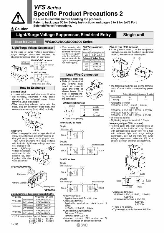
SOL.A
With indicator light
31 2
SOL.B
With indicator light
SOL.A
With indicator light
31 2
SOL.B
With indicator light
SOL.A
With indicator light
31 2
SOL.A
With indicator light
31 2
~
~
SOL.With indicator light
–(+)
+(–)
SOL.With indicator light
Ground
VFS6000
Pilot cover
Mounting screw
Pilot valve assembly
VFS3000/4000/5000/6000 SeriesBase Mounted
Light/Surge Voltage Suppressor Substrate Part No.
VFS4000
VFS3000
VFS5000
VFS6000
VFS3000-10A-#1100V or more24V or less100V or more24V or less100V or more24V or less
VF4000-9A-#1VF4000-9B-#1AXT627-7A-#1AXT627-7B-#1VF4000-9A-#1VF4000-9B-#1
-: Coil rated voltage Symbol: Refer to below.1: 100 to 120 V2: 200 to 220 V5: 24 V
6: 12 V7: 240 V
Light/Surge Voltage Suppressor, Electrical Entry Single unit
Light/Surge Voltage Suppressor
How to Exchange
Lead Wire Connection
In the case of surge voltage suppressor, surge voltage absorption element is attached to terminal block on body area.
100 VAC/DC or more
24 VDC or less
Note) There is no polarity.
Light/Surge voltageabsorption element
Caution
VFS3000/4000/5000
Solenoid valve• Loosen set screw and take solenoid valve
out vertically, otherwise it may cause damage to the solenoid valve. Never remove a valve at an angle.
• When mounting solenoid valve onto the base, plug pin assembly (base side) into receptacle assembly (body side) vertically.
Pilot valve• When changing the rated voltage, electrical
entry, etc., pilot valve assembly can be ex-changed easily since this is plug-in type. Then, when changing the rated voltage with indicator light/surge voltage suppres-sor, change of indi-cator light/surge voltage suppressor substrate is also needed. So, order together with pilot valve assembly.
Plug-in type (With terminal)• If the junction cover (1) of the sub-plate is
removed, you can see the plug-in type terminal block (2) mounted inside the sub-plate.
DIN terminal block type• Male pin terminal of
DIN terminal block board of solenoid valve and wires as shown below. Con-nect to correspond-ing terminal block on the connector.
• There is no polarity.
DIN terminal (Wiring)
123
A sideB sideCOM
Ground
• Heavy-duty cordApplicable cable O. D.: ø8 to ø10
• Applicable terminalApplicable terminal on block board: 3 (kinds) 1.25Y-3L, 1.25-3.5S, 1.25-4M
• Connector/Clamping torqueSet screw 0.6 N·mTerminal screw 0.6 N·m
• Incorrect common (DIN terminal no. 3) causes damage on power side circuit.
Terminal blockmarking
Solenoid A side Solenoid B sideA B
+ – + –
• Applicable terminal:VFS3000: 1.25-3, 1.25-3S, 1.25Y-3N, 1.25Y-3SVFS4000: 1.25-3.5M, 1.25Y-3L, 1.25Y-3MVFS5000: 1.25-4, 1.25-4MVFS6000: 1.25-3.5M, 1.25Y-3L, 1.25-3M
• There is no polarity.• Tightening torque for terminal: 0.6 N·mNon plug-in type (With terminal)• Remove cover (1), over terminal block (2)
attached to the inside of body. Connect with corresponding power side. For a type with indicator light and surge voltage suppressor, pull out the light and surge voltage suppressor substrate (3) in a straight direction and then connect them.
• Applicable terminal:VFS3000: 1.25-3, 1.25-3S, 1.25Y-3N, 1.25Y-3SVFS4000/5000/6000: 1.25-3.5M,
1.25Y-3L, 1.25Y-3M
• There is no polarity.• Tightening torque for terminal: 0.6 N·m
• The following markings are on the terminal block. Connect with corresponding power side.
(1)
(1)
(3)
(2)
(2)
A side
B side
B side
A side
A side B side
Varis
tor
Varis
tor
Varis
tor
Varis
tor
Varis
tor
Varis
tor
Varis
tor
Varis
tor
100 VAC/DC or more
Single
Single
Double
Double
24 VDC or less
• When mounting pilot valve assemblies and solenoid valve bod-ies, tighten equally with the tightening torque shown in the right to prevent gas-kets from slipping.
Pilot Valve AssemblySF4--Holding screw
M3Proper tightening torque (N·m)
0.45 to 0.6
Holding screw
M3M4M5
Proper tightening torque (N·m)0.8 to 1.21.4 to 2.52.8 to 5
Solenoid Valve Body
1010
VFS SeriesSpecific Product Precautions 2Be sure to read this before handling the products.Refer to back page 50 for Safety Instructions and pages 3 to 9 for 3/4/5 Port Solenoid Valve Precautions.

Symbol
P portregulation
A portregulation
B portregulation
B
A
P
R2R1
A
B
P
R2R1R2R1
BA
P
Refer to front matter for How to Calculate the Flow Rate.
How to Calculate the Flow RateCaution Interface Regulator Specifications
Interface regulator (3) (4)
Applicable solenoid valve seriesRegulating portProof pressureMaximum operating pressure
ARBF2000 ARBF3050 ARBF4050 ARBF5050VFS2000 VFS3000 VFS4000 VFS5000
P
M5 x 0.80.165.55.1
P → AP → B
1211
A → EAB → EB
0.4618.5224036
0.7231315545
0.833840
1112
2624
3231
2118.5
3531
4438
9077
A A AB B
Rc 1/8
BP P P
1.0 MPa1.5 MPa
Set pressure range (1) 0.1 to 0.83 MPa0.05 to 0.83 MPaAmbient and fluid temperature –5 to 60°C (No freezing)Port size for connection of pressure gaugeWeight (kg)Effective area at supply side (mm2) (2)
S at P1 = 0.7 MPa, P2 = 0.5 MPa
Effective area at exhaust side (mm2) (2)
S at P2 = 0.5 MPa
Note 1) Set within the operating pressure range of solenoid valve.Note 2) Synthesized effective area with solenoid valve 2 position single type.Note 3) • Operate an interface regulator only by applying pressure from the “P” port of the base, except
when using it as a reverse pressure valve. • To combine a pressure center valve and the A and B port pressure reduction of an interface
regulator, use the ARBF3000, 4000, or 5000 model.• To combine a reverse pressure valve and an interface regulator, use the ARBF3000, 4000, or 5000
model. Furthermore, the P port pressure reduction cannot be used for the reverse pressure valve.• When combining a double check valve and an interface regulator, use a manifold or sub-plate as a
basis, and stack them in the following order; the perfect spacer → the interface regulator → the valve.• When a closed center valve is combined with the interface regulator's A, B port regulation, note
that it cannot be used for intermediate stops of a cylinder because there is leakage from relief port on the regulator.
Note 4) Note that the pressure gauge (G27) for the ARBF2000-00-P- cannot be used for the oil lubricating air.
ARBF3050-00-P
ARBF2000-00-P
ARBF4050-00-P
ARBF5050-00-P
ARBF3050-00-A
ARBF4050-00-A
ARBF5050-00-A
Flow Rate Characteristics (P → A) (Representative value conditions: Inlet pressure 0.7 MPa. when 2 position solenoid valve is mounted.)
Flow rate (L/min (ANR))
Out
let p
ress
ure
(MP
a)
Flow rate (L/min (ANR))
Out
let p
ress
ure
(MP
a)
Flow rate (L/min (ANR))
Out
let p
ress
ure
(MP
a)
Flow rate (L/min (ANR))
Out
let p
ress
ure
(MP
a)
Flow rate (L/min (ANR))
Out
let p
ress
ure
(MP
a)
Flow rate (L/min (ANR))
Out
let p
ress
ure
(MP
a)
Flow rate (L/min (ANR))
Out
let p
ress
ure
(MP
a)
1011
VFS SeriesSpecific Product Precautions 3Be sure to read this before handling the products.Refer to back page 50 for Safety Instructions and pages 3 to 9 for 3/4/5 Port Solenoid Valve Precautions.
SV
SYJ
SZ
VF
VP4VQ1/2
VQ4/5
VQC1/2
VQC4/5
VQZ
SQ
VFS
VFR
VQ7
VFS
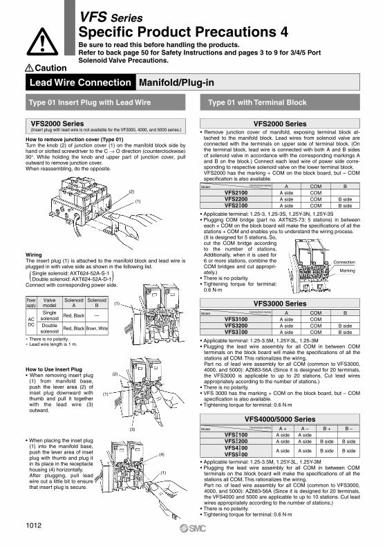
(1)
(2)
(1)
Caution
Lead Wire Connection Manifold/Plug-in
( (
(4)
(1)
(1)
(2)
(3)
Connection
Marking
Type 01 Insert Plug with Lead Wire Type 01 with Terminal Block
VFS2000 Series(Insert plug with lead wire is not available for the VF3000, 4000, and 5000 series.)
VFS2000 Series
VFS3000 Series
VFS4000/5000 Series
How to Use Insert Plug• When removing insert plug
(1) from manifold base, push the lever area (2) of inset plug downward with thumb and pull it together with the lead wire (3) outward.
• When placing the inset plug (1) into the manifold base, push the lever area of inset plug with thumb and plug it in its place in the receptacle housing (4) horizontally.After plugging, pull lead wire out a little bit to ensure that insert plug is secure.
How to remove junction cover (Type 01)Turn the knob (2) of junction cover (1) on the manifold block side by hand or slotted screwdriver to the C → O direction (counterclockwise) 90°. While holding the knob and upper part of junction cover, pull outward to remove junction cover.When reassembling, do the opposite.
• Applicable terminal: 1.25-3.5M, 1.25Y-3L, 1.25-3M• Plugging the lead wire assembly for all COM in between COM
terminals on the block board will make the specifications of all the stations all COM. This rationalizes the wiring.Part no. of lead wire assembly for all COM (common to VFS3000, 4000, and 5000): AZ683-56A (Since it is designed for 20 terminals, the VFS3000 is applicable to up to 20 stations. Cut lead wires appropriately according to the number of stations.)
• There is no polarity.• VFS 3000 has the marking + COM on the block board, but – COM
specification is also available.• Tightening torque for terminal: 0.6 N·m
• Applicable terminal: 1.25-3.5M, 1.25Y-3L, 1.25Y-3M• Plugging the lead wire assembly for all COM in between COM
terminals on the block board will make the specifications of all the stations all COM. This rationalizes the wiring.Part no. of lead wire assembly for all COM (common to VFS3000, 4000, and 5000): AZ683-56A (Since it is designed for 20 terminals, the VFS4000 and 5000 are applicable to up to 10 stations. Cut lead wires appropriately according to the number of stations.)
• There is no polarity.• Tightening torque for terminal: 0.6 N·m
Model Terminal block marking
VFS2100VFS2200VFS2 00
AA sideA sideA side
COMCOMCOMCOM
B
B sideB side3
4
WiringThe insert plug (1) is attached to the manifold block and lead wire is plugged in with valve side as shown in the following list.
Single solenoid: AXT624-52A-S-1Double solenoid: AXT624-52A-D-1
Connect with corresponding power side.
Powersupply
Valvemodel
SinglesolenoidAC
DC Doublesolenoid
SolenoidA
Red, Black
Red, Black
SolenoidB
—
Brown, White
∗ There is no polarity.∗ Lead wire length is 1 m.
Model Terminal block marking
VFS3100VFS3200VFS3 00
AA sideA sideA side
COMCOMCOMCOM
B
B sideB side3
4
Model Terminal block marking
VFS 100VFS 200VFS4 00VFS5 00
A +A sideA side
A side
A –A sideA side
A side
B +
B side
B side
B –
B side
B side34
4545
34
• Applicable terminal: 1.25-3, 1.25-3S, 1.25Y-3N, 1.25Y-3S• Plugging COM bridge (part no. AXT625-73: 5 stations) in between
each + COM on the block board will make the specifications of all the stations + COM and enables you to understand the wiring process.(It is designed for 5 stations. So, cut the COM bridge according to the number of stations. Additionally, when it is used for 6 or more stations, combine the COM bridges and cut appropri-ately.)
• There is no polarity.• Tightening torque for terminal:
0.6 N·m
• Remove junction cover of manifold, exposing terminal block at-tached to the manifold block. Lead wires from solenoid valve are connected with the terminals on upper side of terminal block. (On the terminal block, lead wire is connected with both A and B sides of solenoid valve in accordance with the corresponding markings A and B on the block.) Connect each lead wire of power side corre-sponding to respective solenoid valve on the lower terminal block.VFS2000 has the marking + COM on the block board, but – COM specification is also available.
1012
VFS SeriesSpecific Product Precautions 4Be sure to read this before handling the products.Refer to back page 50 for Safety Instructions and pages 3 to 9 for 3/4/5 Port Solenoid Valve Precautions.

Multi-connector
Standard wiring Wiring with control unit
D-sub connector
Standard wiring Wiring with control unit
Pressure switch
2423
22COM
SOL.BSOL.A
7 station 2120
19COM
SOL.BSOL.A
6 station 1817
16COM
SOL.BSOL.A
5 station 1514
13COM
SOL.BSOL.A
4 station 1211
10COM
SOL.BSOL.A
3 station 98
7COM
SOL.BSOL.A
5
4
Connector terminal no.
2
1
Air release valve
2423
22COM
SOL.B
SOL.A
7 station 2120
19COM
SOL.B
SOL.A
6 station 1817
16COM
SOL.B
SOL.A
5 station 1514
13COM
SOL.B
SOL.A
4 station 1211
10COM
SOL.B
SOL.A
3 station 98
7COM
SOL.B
SOL.A
2 station 65
4COM
SOL.B
SOL.A
1 station
Connector terminal no.
32
1COM
SOL.B
SOL.A
1224
25COM
SOL.BSOL.A
7 station 2310
11COM
SOL.BSOL.A
6 station 921
22COM
SOL.BSOL.A
5 station 207
8COM
SOL.BSOL.A
4 station 618
19COM
SOL.B
SOL.A
3 station 174
5COM
SOL.BSOL.A
Connector terminal no.
1224
25COM
SOL.BSOL.A
7 station 2310
11COM
SOL.BSOL.A
6 station 921
22COM
SOL.BSOL.A
5 station 207
8COM
SOL.BSOL.A
4 station 618
19COM
SOL.BSOL.A
3 station 174
5COM
SOL.BSOL.A
2 station 315
16COM
SOL.BSOL.A
1 station
Connector terminal no.
141
2COM
SOL.BSOL.A
15
16
1
2
Caution
Type 01F D-sub Connector
VFS2000/3000/4000/5000 Series VFS2000/3000/4000/5000 Series
Lead Wire Connection Manifold/Plug-in
Type 01C Circular Connector
Note 1) Maximum stations are 8.Note 2) There is no polarity.Note 3) Indication of stations are one station from D side regardless of the
connector mounting side, D or U.
• Wire connection specificationsLead wire for both solenoid A and B sides in manifold are connected to connector terminal as COM specifications.
• Wire connection specificationsLead wire for both solenoid A and B sides in manifold are connected to connector terminal as COM specifications.
Internal Wiring of Manifold
Applicable Plug Assembly (Option)
VVFS2000-30A-1VVFS2000-30A-2
Assembly part no. Cable length1.5 m3 m
VVFS2000-30A-3 5 mVVFS2000-30A-4 ∗ 7 mVVFS2000-30A-5 ∗ 10 mVVFS2000-30A-6 ∗ 15 mVVFS2000-30A-7 ∗ 20 m
Component parts
Plug 206837-1 1 pc. Cable clamp 206138-1 1 pc. Socket 66101-2 24 pcs. Cable VCTF 24 cores x 0.75 mm2
made by Tyco Electronics AMP K.K.
∗ Option
Cable Color List of Each Terminal No.Terminal no. 1
Orange Orange
—
2
Yes Yes Yes Yes Yes Yes
3Black Black
—
4 5
—
6Green Green Red Red Blue Blue Yellow Yellow
7
—
8 9
—
10 11
—
12Lead wire colorDot marking
Terminal no.Lead wire colorDot marking
Cable Color List of Each Terminal No.Terminal no. 1
Black Brown
— —
2
White Black Red Red
3Red Orange
— —
4 5
— —
6Yellow Pink Blue Purple Gray White White Yellow
7
—
8 9
Black
10 11 12Lead wire color
Note 1) Maximum stations are 8.Note 2) There is no polarity.Note 3) Indication of stations are one station from D side regardless of the
connector mounting side, D or U.
Internal Wiring of Manifold
Applicable Plug Assembly (Option)
AXT100-DS25-015AXT100-DS25-030
Assembly part no. Cable length1.5 m3 m
AXT100-DS25-050 5 mAXT100-DS25-080 8 mAXT100-DS25-100 10 mAXT100-DS25-150 15 mAXT100-DS25-200 30 m
Component parts
AXT100-DS25-300 20 m
Dot marking
Terminal no.Lead wire colorDot marking Black Black BlackWhite White White WhiteRed
Yellow Pink Blue Purple Gray Orange Red Brown Pink
14 15 16 17
—
18 19
— —
20 21 22
Red
Gray Black White
23 24 25
Fig. (1) U side
D side
Fig. (2) U side
D side
Plug: MIL standard D type connector25 terminals Cable: 25 cores wire x 0.3 mm2
Applicable plug assembly (Option)
(1)(2)
(3)(n)
(1)(2)
(3)(n)
Applicable plug assembly (Option)
Connector terminal no.
1station
2station
Con
trol u
nit
Max.8 stations
Max.8 stations
Connectorterminal no.
Air release valve1station
2station
Pressure switch
Con
trol u
nit
Max.8 stations
Max.8 stations
23
Yes Yes Yes Yes Yes
Brown Brown White White Pink Pink Gray Gray Sky blue Sky blue Light green Light green
13
—
14 15
—
16 17
—
18 19
—
20 21
—
22 24
Yes—
StationsStations
Red
Orange
13
1013
VFS SeriesSpecific Product Precautions 5Be sure to read this before handling the products.Refer to back page 50 for Safety Instructions and pages 3 to 9 for 3/4/5 Port Solenoid Valve Precautions.
SV
SYJ
SZ
VF
VP4VQ1/2
VQ4/5
VQC1/2
VQC4/5
VQZ
SQ
VFS
VFR
VQ7
VFS