The importance of the scalp in head impact kinematics
24
The importance of the scalp in head impact kinematics Antonia Trotta 1 , Dimitris Zouzias 3,5 , Guido De Bruyne 3, 4 , Aisling Ní Annaidh 1, 2 1 School of Mechanical & Materials Engineering, University College Dublin, Belfield, Dublin 4, Ireland 2 UCD Charles Institute of Dermatology, School of Medicine and Medical Science, University College Dublin, Belfield, Dublin 4, Ireland 3 LazerSport, Lamorierestraat 33, Antwerp, Belgium 4 Product Development, Faculty of Design Sciences, University of Antwerp, Antwerp, Belgium 5 Department of Materials Engineering, KU Leuven, Leuven, Belgium Address for correspondence Dr. Aisling Ní Annaidh UCD School of Mechanical & Materials Engineering University College Dublin Belfield, Dublin 4, Ireland Phone: +353 1 716 1889 E-mail: [email protected]
-
Upload
khangminh22 -
Category
Documents
-
view
0 -
download
0
Transcript of The importance of the scalp in head impact kinematics

The importance of the scalp in head impact kinematics
Antonia Trotta1, Dimitris Zouzias3,5, Guido De Bruyne3, 4, Aisling Ní Annaidh1, 2
1 School of Mechanical & Materials Engineering, University College Dublin, Belfield, Dublin
4, Ireland
2 UCD Charles Institute of Dermatology, School of Medicine and Medical Science, University
College Dublin, Belfield, Dublin 4, Ireland
3 LazerSport, Lamorierestraat 33, Antwerp, Belgium
4 Product Development, Faculty of Design Sciences, University of Antwerp, Antwerp,
Belgium
5 Department of Materials Engineering, KU Leuven, Leuven, Belgium
Address for correspondence
Dr. Aisling Ní Annaidh
UCD School of Mechanical & Materials Engineering
University College Dublin
Belfield, Dublin 4, Ireland
Phone: +353 1 716 1889
E-mail: [email protected]

2
Abstract
The best way to reduce the risk of head injury (up to 69% reduction) is to wear a helmet. In
recent years, the improvement of helmet standard tests focused on reproducing realistic
impact conditions and including the effect of rotational acceleration. However, less
importance has been given to the development of a realistic headform. The goal of this
work was to evaluate the role of scalp tissue in head impact kinematics; both with respect
to its mechanical properties and with respect to its sliding properties. An EN960 and HIII
headform were subjected to linear and oblique impacts, respectively, both with and without
porcine scalp attached. Different speeds, impact locations and impact surfaces were tested.
Standard linear drop tests (EN960) showed that the scalp reduced the impact energy by up
to 68.7% (rear impact). Oblique head impact tests showed how the headform-anvil friction
coefficient changes when the HIII is covered with scalp, affecting linear and rotational
accelerations. Therefore, the scalp plays an important role in head impacts and it should be
realistically represented in headforms used for impact tests and in numerical models of the
human head.
Key words: Head impacts, head injuries, scalp, head protection, helmet standard tests,
friction coefficient, skin.

3
1. Introduction
Researchers agree that the best way to protect the head in many sports is to wear a helmet.
A number of studies have shown that, by absorbing impact energy2, 3, 19, 26, 30, 31, the use of a
helmet in cycling, for example, reduces the risk of head injuries by 69% and the risk of brain
injury by 65%. Currently, sport and automotive helmets are all tested for radial impacts
only, except for the BS 6658 and EN 22.05 oblique impact tests for motorcycle helmets.
However, recently these tests have come under scrutiny for two main reasons: the first
argument is that a radial impact is not representative of the most common impact scenario
which is typically an oblique impact6, 25, 27, 34 with an impact angle between 21º and 60º
depending on whether it is a motorcycling, skiing, equestrian or cycling fall15, 25, 34; the
second argument is that rotational acceleration is potentially a better indicator of head
injury than linear acceleration. This is because the brain is more sensitive to shear forces
resulting from rotational and linear acceleration, than to compressive forces due to linear
acceleration alone12, 13, 18, 21, 22. Another source of debate has been the test impact surface,
both in terms of selecting an appropriate material stiffness and coefficient of friction1, 15, 24.
The coefficient of friction plays an important role in oblique impacts, affecting the rotational
kinematics of the headform substantially. A number of researchers have focused their
attention on the relative sliding properties between head and helmet, showing that a lower
friction decreases the rotational acceleration undergone by the head during the impact, and
therefore the risk of head injury 1, 11, 15, 16. Indeed, this insight has led to the development of
new helmet designs which exploit this attribute. Conversely, other works have shown that a
lower head-helmet friction, in some cases, increases the rotational acceleration undergone
by the head, depending on impact location and angle10, 11. Ebrahimi et al10 performed
oblique impact tests on a bare magnesium headform and then covered the headform with a

4
silicone layer to study how this layer affected the impact mechanics. They tested only one
impact location (rear lateral), reporting an increase in rotational acceleration of 89% (anvil
30 degrees) when the headform is covered with a silicone layer. The researchers concluded
that the material covering the headform, and its sliding properties, are of the utmost
importance.
A number of artificial headforms have been developed over the years for different
applications: The magnesium EN960, which is mainly used for helmet standard tests; the
Hybrid III dummy headform (HIII), initially developed for vehicle crash testing and currently
also used in sport biomechanics and military safety; the National Operating Committee on
Standards for Athletic Equipment (NOCSAE) headform developed for testing sport helmets;
and the Facial and Ocular Countermeasure Safety (FOCUS) headform, developed by the
Virginia Tech – Wake Forest Center for Injury Biomechanics, Robert A. Denton, Inc., and the
United States Army Aeromedical Research Laboratory, mainly used for safety devices to
prevent face and eye injury. The magnesium EN960 does not have an outer layer to simulate
scalp tissue. The HIII, NOCSAE and FOCUS headform have an external polymer layer
simulating the scalp tissue.
Being the external tissue of the head, the scalp is the first tissue involved in a head impact. It
is made up of five principal layers32 to form the acronym SCALP: Skin, Connective tissue
(dense), Aponeurosis, Loose connective tissue and Periosteum. The thickness of the scalp
depends on age and location29 and this value can vary between 3 mm in children and 8 mm
in adults35. The loose connective tissue, which allows for the movements of the scalp on the
skull, is anteriorly connected with the orbicularis oculi muscles, laterally connected to the
frontal process of the zygoma, to the superior aspect of the zygomatic arch and over the
mastoid process superior to the attachments of the sternocleidomastoid and trapezius

5
muscles, and in the back of the head it fuses with the superior nuchal line32. An apparent
function of the scalp is to absorb and distribute external forces and to reduce the severity of
impacts, by sliding freely over the skull. Only a few works have tried to investigate the effect
of the scalp in impact tests; Gurdjian (1972) performed experimental tests on cadavers14
demonstrating that the impact force undergone by the head without the scalp is up to 35%
higher than with the presence of scalp, depending on the impact angle between the impact
surface and the head; other works used numerical and mathematical models9, 17, 20 showing
that the presence of scalp dampens the magnitude of the impact force by increasing the
contact area and the duration of the impact.
The aim of this work is to evaluate the effect of the presence of scalp tissue during both
linear and oblique impacts and compare the scalp behaviour with two widely used artificial
headforms for impact tests (magnesium EN960 and HIII).
2. Materials and methods
Experimental tests were conducted at Lazer Sport using a free fall impact machine and two
different types of headform, EN960 (magnesium headform) and HIII (Hybrid III dummy
head). The EN960 is equipped with 3 accelerometers and it was used only for linear impacts;
the HIII is equipped with 9 accelerometers and it was used for oblique impacts. The impact
machine is a monorail vertical drop tower (Ad Engineering srl) of 5.5 m height. The
headform is placed in an aluminium circular (U-shape for oblique impact) carrier with 8 soft
small balls (Figure 1a). An automatic hooking system of the carriage keeps the headform in
place during the descent. 0.5 m before the impact the hooking system is released. In the
anvil holder, a laser pointer tracks the point of impact on the helmet. Data was collected at
a rate of 50 kHz and tests were recorded with a high speed camera to monitor the quality of

6
the impact. Since porcine skin is widely accepted as the most accurate model for human skin
in terms of anatomy 4, 33 and morphology 23, porcine scalp was chosen as a substitute for
human scalp in the present study. Porcine scalp, obtained from a local abattoir and stored in
a freezer at -20°C, was used to cover the headform and it was connected to the headform at
the relevant anatomical points of connection using superglue. The thickness of the porcine
scalp was between 3 and 7 mm, values comparable with the human scalp (3-8 mm)35. Both
linear and oblique impacts were performed. The purpose of the linear impacts was to
determine the energy absorbed by the scalp, while minimizing the effect of the sliding
interaction. The purpose of the oblique impacts was to determine the effect of the scalp in a
realistic impact where the sliding interaction plays an important role. The effect of three
main factors was considered during the tests: impact location, impact speed and impact
surface. All the tests were conducted at room temperature. The effectiveness of the scalp
was quantified through the evaluation of energy absorption, linear and rotational
acceleration, angular velocity and impact time.
2.1 Linear impact
Linear impact tests were conducted using the EN960 full magnesium headform representing
the 50th percentile male head, with/without adding scalp tissue. The EN960 headform is
equipped with three accelerometers (measuring range of ±500 g) placed at the centre of
gravity of the headform. The mass of the fully instrumented magnesium EN960 was 4.69 Kg.
The impact height chosen was of 140 cm, resulting in an impact speed of ~5 m/s. A
polymeric (modular elastomer programmer MEP made of polyurethane rubber with
hardness 60 Shore A) flat anvil (0.5 Kg, 130 mm diameter and 30 mm thickness) was used in
order to avoid damaging the accelerometers due to a steel-on-steel impact. Four different

7
impact locations were tested: top, front, side and rear as showed in Figure 1. The first set of
tests was performed using the bare EN960; the second set adding porcine scalp tissue on
the headform. Approximately one third of the headform was covered with scalp. The scalp
was glued to the headform around the impact area at the relevant anatomical points to
keep the scalp in place during the test. A total of 48 tests were performed, 12 using the
EN960 (three repetitions for each location), 36 using the EN960+Scalp (three scalps per
location, three repetitions per scalp).
Values of the linear acceleration in the three different directions are obtained as a result of
the impact test. Data was filtered using a Butterworth filter (cut off frequency 1700 Hz) in
Matlab and the resultant acceleration between the bare EN960 and EN960+Scalp was
compared in terms of average and standard deviation. The energy absorbed during the
impact was calculated as the difference in kinetic energy between the initial and the final
point of the impact. Energy converted in angular momentum has been neglected. The
difference between the energy absorbed by the bare EN960 and the EN960+Scalp
represents the energy absorbed by the scalp. In order to calculate the impact time a
threshold of 4 g (about 1% of the maximum peak value) was chosen for the starting and
ending points. The final velocity was calculated as the integral of the acceleration pulse over
the impact time. A two-way ANOVA test was used to compare the maximum peak
acceleration, the impact time and the energy absorbed during the impact. A statistical
analysis was also performed on the 1st, 2nd and 3rd test performed on the same scalp to
evaluate if the scalp was damaged during the impact.

8
Figure 1: a) Free fall impact machine with close up of the circular carrier which holds the headform during linear impacts. b) Locations of the linear impact tests: front, top, rear and side.
2.2 Oblique impact
Oblique impact tests were performed to replicate conditions closer to realistic impact
scenarios. During an impact, the impact velocity is typically not perpendicular to the ground
but it is oblique, with an angle between 21 and 60º, depending on the sport15, 25. A 45º
oblique stainless steel anvil (8.2 Kg) and an HIII headform (equipped with 9 accelerometers)
representing the 50th percentile male head were used for these tests. The mass of the fully
instrumented HIII was 4.54 kg. Two different configurations of the headform were tested,
HIII and HIII covered with porcine scalp. Approximately one third of the headform was
covered with scalp. Before placing the scalp on the headform, the vinyl layer of the HIII was
covered with tape to reduce the friction between the scalp and the headform. Impact tests
were performed in three different locations (Figure 2), Xrot, Yrot and Zrot with three
repetitions per location. An inclinometer was used to check that the base plate of the

9
headform was horizontal in Xrot and Yrot, and that there was a 20º angle in Zrot. A number
of scenarios were tested in sequence (Figure 3): (1) the headform was dropped at 3.5 m/s
on the oblique anvil without helmet. The speed of 3.5 m/s was chosen so as not to damage
the accelerometers. (2) A Roller Lazer® helmet was added to the headform; (3) sand paper
(grid 40) was glued to the anvil in order to increase the helmet-anvil friction coefficient and
to represent a more realistic impact surface; (4) the impact speed was increased to 6.5 m/s.
Figure 2: Impact locations tested for oblique impacts.
Figure 3: Different scenarios for oblique impact tests: (1) headform impact at 3.5 m/s on a 45°metal anvil; (2)
headform impact with helmet at 3.5 m/s on a 45° metal anvil; (3) headform impact with helmet at 3.5 m/s on a 45° metal anvil covered with sand paper; (4) headform impact with helmet at 6.5 m/s on a 45° metal anvil
covered with sand paper.
Using MATLAB, results were analysed in terms of resultant linear acceleration, resultant
rotational acceleration, resultant angular velocity, impact time and energy absorbed during

10
the impact. A Butterworth filter (cut off frequency 1700 Hz) was applied to remove noise
from the data. The energy absorbed by the headform during the impact has been
determined as the difference in kinetic energy between the initial point of the impact and
the final point. In this case, the kinetic energy is given by the sum of a linear and a rotational
component:
𝐾𝐸 = 1/2(𝑚𝑣 + 𝐼𝑤 )
Where m is the mass of the headform (HIII mass = 4.53 kg), v is the linear velocity, I is the
moment of inertia of the HIII (Iyy=0.0241 kgm2, Ixx=0.0159 kgm2, Izz=0.0221 kgm2) 8 and w is
the angular velocity. It should be noted that only the energy absorbed by the headform has
been calculated in this case because the accelerometer data pertains to the headform. The
impact time was calculated considering a threshold of 2 g (about 1% of the maximum peak
value) for the starting point and a threshold of 200 rad/s2 as final point of the rotational
acceleration. A multi-way ANOVA test was used to compare the results obtained with the
HIII and with the HIII covered with porcine scalp. In particular, maximum values of the
linear/rotational acceleration, angular velocity, impact time and energy absorbed during the
impact were compared.
3. Results
3.1 Linear impact
The linear acceleration undergone by the EN960 (continuous blue line) and by the EN960
covered with scalp (dashed red line) is shown in Figure 4 in terms of average and standard
deviation. The scalp reduces the peak acceleration by increasing the impact duration and
the contact area. In the top impact there is a 17% reduction in terms of peak acceleration
and an 11% increase in impact time; in the front impact an 18% reduction in peak

11
acceleration with a 13% increase in impact time; the side impact showed a 20% reduction in
peak acceleration and a 17% increase in impact time; and the rear impact showed a 26%
reduction in peak acceleration and a 12% increase in impact time.
Figure 4: Resultant linear acceleration resulting from the linear impact tests in four different locations. The continuous blue line represents the results for the bare EN960, the dashed red line the results for the EN960
covered with porcine scalp. The shaded line represents the standard deviation.
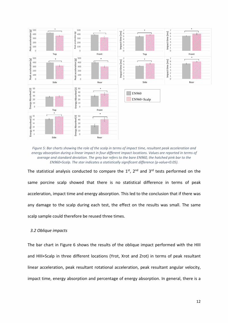
Values of the impact time, peak acceleration and energy absorbed during the impacts are
shown in the bar charts (Figure 5) in grey for the bare EN960 and in hatched pink for the
EN960 covered with porcine scalp. It can be seen that the presence of scalp increases the
impact time and reduces the acceleration peak. This led to a rise in the energy absorbed
during the impact of 3% in top impacts, 19% in front impacts, 16% in side impact and 69% in
rear impacts. The difference of energy absorbed during the impact between the EN960 and
the EN960+Scalp represents the energy absorbed by the scalp. Statistical analysis showed
that there is statistical difference between EN960 and EN960+Scalp in impact time,
acceleration peak and energy absorbed during the impact for all the impact locations.
12
Figure 5: Bar charts showing the role of the scalp in terms of impact time, resultant peak acceleration and energy absorption during a linear impact in four different impact locations. Values are reported in terms of
average and standard deviation. The grey bar refers to the bare EN960, the hatched pink bar to the EN960+Scalp. The star indicates a statistically significant difference (p-value<0.05).
The statistical analysis conducted to compare the 1st, 2nd and 3rd tests performed on the
same porcine scalp showed that there is no statistical difference in terms of peak
acceleration, impact time and energy absorption. This led to the conclusion that if there was
any damage to the scalp during each test, the effect on the results was small. The same
scalp sample could therefore be reused three times.
3.2 Oblique impacts
The bar chart in Figure 6 shows the results of the oblique impact performed with the HIII
and HIII+Scalp in three different locations (Yrot, Xrot and Zrot) in terms of peak resultant
linear acceleration, peak resultant rotational acceleration, peak resultant angular velocity,
impact time, energy absorption and percentage of energy absorption. In general, there is a
13
reduction in terms of linear and rotational acceleration, and an increase in impact time and
rotational velocity in the test HIII+Scalp but this is not always the case.
First scenario: In this configuration, the presence of the scalp significantly reduced the linear
peak acceleration with a reduction of 24% in Yrot, 25% in Xrot, and 32% in Zrot. The
presence of scalp tissue affects the rotational acceleration with a significant reduction in
Yrot and Xrot (by 70% and 16% respectively) but an increase by 51% in Zrot. The angular
velocity is reduced by 52% in Yrot and increased by 74% and 92% in Xrot and Zrot
respectively when the HIII is covered with scalp. The duration of the impact increases
significantly with the presence of scalp in Xrot and Yrot but there is no statistical difference
in Zrot. The energy absorbed during the impact is lower for the headform alone than the
combined headform and scalp configuration. The difference represents the energy absorbed
by the scalp. The scalp absorbs a noticeable percentage of energy in Xrot and Zrot (15% and
28% respectively).
Second scenario: In this scenario, the helmet was added to the system. As expected, the
presence of the helmet decreases the linear and rotational acceleration, the angular velocity
and increases the impact time. The presence of the scalp between the HIII and the helmet
further reduces the peak linear acceleration by 6% (Yrot), 13% (Xrot), and 19% (Zrot)
respectively; the rotational acceleration reduces by 39% (Yrot), and 6% (Zrot) and increases
by 7% (Xrot). The angular velocity shows a decrease of 38% in Yrot and an increase of 15%
and 11% in Xrot and Zrot respectively. The duration of the impact always increases when
the scalp is present. The energy absorbed by the headform is lower than in the first
scenario, since the helmet is absorbing part of the energy, but there is a statistical

14
difference between the HIII and the HIII+Scalp only in the Zrot where the presence of the
scalp further reduces the energy absorbed by 10%.
Third scenario: In this case sand paper was added to the surface of the anvil in order to
reproduce a more realistic impact surface. The presence of the sand paper has only a small
effect on the linear acceleration, the impact time and energy absorption, but substantially
affects the rotational acceleration and the angular velocity. The presence of the scalp, in this
case, reduces the linear acceleration peak of 3% (Yrot), 8% (Xrot) and 12% (Zrot); the
rotational acceleration, shows a decrease of 53% (Yrot), 58% (Xrot), and an increase by 28%
(Zrot). The angular velocity shows a reduction of 67% (Yrot), 64% (Xrot) and an increase of
27% (Zrot). A statistical analysis revealed a significant difference in the values of rotational
acceleration in Xrot and Yrot but not in Zrot, and a significant difference in the value of
angular velocity.
Fourth scenario: In this scenario the speed of the tests was increased to 6.5 m/s. The higher
speed affects the linear and rotational acceleration, the angular velocity and the energy
absorption. The presence of the scalp reduces the peak linear acceleration by 10% (Yrot),
10% (Xrot), and 32% (Zrot); the rotational acceleration shows the same behaviour with a
reduction of 54% (Yrot), 49% (Xrot), and 44% (Zrot) with the presence of scalp tissue. With
the presence of scalp, the angular velocity decreases by 32% (Yrot), 35% (Xrot), and 24%
(Zrot). The energy absorbed by the headform increases in magnitude with respect to the
previous scenarios but the relative improvement with the presence of the scalp stays the
same, except in the Zrot where the difference is statistically significant. In this case, there is
always a significant difference in terms of rotational acceleration and angular velocity when
the HIII is covered with scalp.

15
Figure 6: Bar chart showing the results of the oblique impacts in terms of resultant peak linear acceleration, resultant peak rotational acceleration, resultant peak angular velocity, impact time, energy absorbed and percentage of energy absorbed. Values are reported in terms of average and standard deviation. The star identifies statistical difference (p-value<0.05).

16
4. Discussion
Scalp tissue has a significant effect in head impact biomechanics, reducing the impact force
experienced by the head. A general overview of the results shows that the scalp reduces the
linear and rotational acceleration and increases the energy absorbed during the impact, but
this is not always the case. A number of factors need to be considered when adding the
scalp to an impact test: the mechanical properties of the scalp tissue, scalp-headform sliding
interactions, scalp (or helmet)-impact surface sliding interactions and scalp-helmet sliding
interactions. Linear impacts were chosen in order to evaluate the effect of the mechanical
properties of the scalp in an impact, while trying to minimise the effect of the sliding
properties. Results showed that the presence of the scalp on the EN960 reduced the peak
acceleration (up to 25%) and increased the energy absorbed during the impact (up to 69%)
but that the effect of the scalp depends on the impact location.
The sliding interactions in head impacts have become a topic of interest in recent years, as
many researchers argue that a lower scalp-helmet friction reduces the rotational
acceleration experienced by the head during an impact1, 15, 16 and others that the friction
between the scalp and the helmet does not always reduce the rotational acceleration10, 11.
In order to include the effect of the friction coefficient, oblique impact tests were conducted
examining the effect of different impact surfaces and different speeds. In addition to the
mechanical properties of the scalp, in the oblique impacts, the sliding properties play an
important role. In this scenario there are different friction coefficients at play: scalp-skull
friction, which is extremely low since in the human head the scalp can easily slide over the
skull32; scalp-helmet friction; and helmet-impact surface friction. Considering the first test
scenario, where there is no helmet present, the presence of the scalp results in a significant
reduction in both linear and rotational acceleration, except for Zrot, where the impact

17
kinematics are significantly different. The reduction in linear acceleration is mainly due to
the mechanical properties of the scalp; however the significant reduction in rotational
acceleration is due to the combination of mechanical properties and sliding properties. In
the case of Zrot, there is a significant increase in rotational acceleration because the
kinematics of the impact is altered. Analysing the videos of the impact (Figure 7), it is
possible to see how different HIII/anvil friction and Scalp/anvil friction results in a different
motion of the headform. The HIII indeed touches the anvil and bounces almost
perpendicularly from the anvil. The scalp, however, contacts the anvil and slides along it,
due to the low scalp-anvil friction. This illustrates the very important role of the coefficient
of friction between the outer layer of the headform (silicone / steel / helmet shell) and the
impact surface (steel / rubber / sandpaper).
Figure 7: Sequence of pictures of the oblique impact for the HIII and HIII+Scalp showing the different kinematics of the impact due to the different friction coefficient of scalp-anvil and HIII-anvil. This results in the headform
either rebounding off the anvil, or sliding along it.

18
The objective of a helmet is to absorb energy and reduce the linear and rotational
acceleration, and the angular velocity. Comparing the first and second test scenario, the
effectiveness of the helmet is clear. The presence of the helmet reduces the relative effect
of the scalp, since the helmet is designed to absorb energy and the speed, in this scenario, is
only of 3.5 m/s. Adding sand paper to the anvil (third test scenario), however, increases the
difference in rotational acceleration between the HIII and the HIII+Scalp. Comparing the
second and third scenarios, it is possible to see how a low friction helmet-impact surface
increases the sliding of the helmet over the impact surface but reduces the sliding of the
helmet over the scalp, resulting in a small difference between the HIII and the HIII+Scalp. A
higher friction helmet-impact surface (sand paper), instead, reduces the sliding of the
helmet over the surface promoting the sliding of the scalp inside the helmet. This factor
results in a larger difference in the impact mechanics between the HIII and HIII+Scalp,
confirming the different friction properties of the HIII vinyl layer and the scalp tissue. The
last test scenario illustrated the effect of the speed; higher speeds increase the
linear/rotational acceleration and angular velocity peaks and increase the difference
between HIII and HIII+Scalp. At 6.5 m/s and with sand paper on the anvil, the scalp
significantly reduces the rotational acceleration and the angular velocity undergone by the
head during the impact.
It has been previously observed in the literature that the HIII vinyl layer has a very high
coefficient of friction, indeed, in an effort to reduce this friction, a number of NFL helmet
studies have covered the vinyl layer with a nylon skullcap5, 7, 28. While perhaps this approach
represents a headform-helmet sliding worst-case scenario, it does not offer a realistic
analysis of the role of the scalp in head impacts, nor a quantitative measure of the energy
absorbed by the scalp. Although the present study used frozen porcine scalp in place of

19
human scalp, and the presence of hair was not considered (which could further reduce the
scalp-liner friction), the results reported provide new insights into the role of the scalp in
head impacts and its importance in both helmet impact testing and numerical head impact
simulations.
5. Conclusion
It is clear that scalp tissue affects head impact biomechanics in a significant way. In general,
the presence of the scalp reduces the linear/rotational acceleration (3-70% of reduction
depending on speed, type of impact, presence of helmet, impact surface and impact
location). However, oblique impacts showed that the friction coefficients of the scalp and
the HIII vinyl layer are so different that it causes an important change in the motion of the
impact (Figure 7). This has the effect of changing the rotational acceleration experienced by
the headform (16-70% difference for oblique impact without helmet). Knowledge of both
mechanical properties and sliding interactions of scalp tissue is therefore essential to better
understand and simulate head impacts. Furthermore, the introduction of new standard
helmet tests, which includes the effect of rotational acceleration, should pay close attention
to the selection of an appropriate headform and its relative sliding properties.
This work showed the importance of a realistic scalp substitute in impact tests especially for
oblique impact tests and how this can affect and improve helmet design. Future work
should focus on the identification of a realistic scalp substitute or improved headform for
oblique head impacts and on the study of the relevant sliding interactions in head impacts.
Acknowledgements

20
Funding was provided by the European Union’s Horizon 2020 research programme under
the Marie Sklodowska – Curie grant agreement No. 642662. The authors would like to
acknowledge KU Leuven for the use of the high speed camera and Lazer Sport for the use of
the impact set-up.
Conflict of interest
The authors have no relevant conflict of interest to report.
References
1. Aare, M. and P. Halldin, A new laboratory rig for evaluating helmets subject to
oblique impacts. Traffic injury prevention, 2003. 4(3): p. 240-248.
2. Amoros, E., M. Chiron, J.-L. Martin, B. Thélot, and B. Laumon, Bicycle helmet wearing
and the risk of head, face, and neck injury: a French case–control study based on a
road trauma registry. Injury Prevention, 2012. 18(1): p. 27-32.
3. Attewell, R.G., K. Glase, and M. McFadden, Bicycle helmet efficacy: a meta-analysis.
Accident Analysis & Prevention, 2001. 33(3): p. 345-352.
4. Avon, S. and R. Wood, Porcine skin as an porcine skin as an in-vivo model for model
for ageing of human bite marks. J. Forensic Odontostomatol, 2005. 23: p. 30-39.
5. Beckwith, J.G., R.M. Greenwald, and J.J. Chu, Measuring head kinematics in football:
correlation between the head impact telemetry system and Hybrid III headform.
Annals of biomedical engineering, 2012. 40(1): p. 237-248.
6. Bourdet, N., C. Deck, R.P. Carreira, and R. Willinger, Head impact conditions in the
case of cyclist falls. Proceedings of the Institution of Mechanical Engineers, Part P:
Journal of Sports Engineering and Technology, 2012. 226(3-4): p. 282-289.

21
7. Campbell, K.R., M.J. Warnica, I.C. Levine, J.S. Brooks, A.C. Laing, T.A. Burkhart, and
J.P. Dickey, Laboratory evaluation of the gForce Tracker™, a head impact kinematic
measuring device for use in football helmets. Annals of biomedical engineering,
2016. 44(4): p. 1246-1256.
8. CEN/TC 158/WG 11 N 185 - Headforms and test methods. European Commission, B.,
Belgium. 2015.
9. Chan, H.S., Mathematical model for closed head impact. 1974, SAE Technical Paper.
10. Ebrahimi, I., F. Golnaraghi, and G.G. Wang, Factors influencing the oblique impact
test of motorcycle helmets. Traffic injury prevention, 2015. 16(4): p. 404-408.
11. Finan, J.D., R.W. Nightingale, and B.S. Myers, The influence of reduced friction on
head injury metrics in helmeted head impacts. Traffic injury prevention, 2008. 9(5): p.
483-488.
12. Forero Rueda, M.A., L. Cui, and M.D. Gilchrist, Finite element modelling of equestrian
helmet impacts exposes the need to address rotational kinematics in future helmet
designs. Computer methods in biomechanics and biomedical engineering, 2011.
14(12): p. 1021-1031.
13. Gennarelli, T.A., L.E. Thibault, G. Tomei, R. Wiser, D. Graham, and J. Adams,
Directional dependence of axonal brain injury due to centroidal and non-centroidal
acceleration. 1987.
14. Gurdjian, E.S., Recent advances in the study of the mechanism of impact injury of the
head--a summary. Clinical neurosurgery, 1972. 19: p. 1-42.
15. Halldin, P. and S. Kleiven. The development of next generation test standards for
helmets. in Proceedings of the 1st International Conference on Helmet Performance
and Design. 2013.

22
16. Halldin, P., D. Lanner, R. Coomber, and S. Kleiven. Evaluation of blunt impact
protection in a military helmet designed to offer blunt and ballistic impact protection.
in Childs PRN, Bull A, Ghajari M, editors. Proceedings of the first International
Conference on Helmet Performance and Design. 2013.
17. Hardy, C.H. and P.V. Marcal, Elastic analysis of a skull. 1971: Division of Engineering,
Brown University.
18. Holbourn, A., Mechanics of head injuries. The Lancet, 1943. 242(6267): p. 438-441.
19. Keng, S.-H., Helmet use and motorcycle fatalities in Taiwan. Accident Analysis &
Prevention, 2005. 37(2): p. 349-355.
20. Khalil, T.B., W. Goldsmith, and J. Sackman, Impact on a model head-helmet system.
International Journal of Mechanical Sciences, 1974. 16(9): p. 609-625.
21. Kleiven, S., Predictors for traumatic brain injuries evaluated through accident
reconstructions. Stapp car crash journal, 2007. 51: p. 81.
22. Kleiven, S., Why most traumatic brain injuries are not caused by linear acceleration
but skull fractures are. Frontiers in bioengineering and biotechnology, 2013. 1.
23. Lavker, R.M., G. Dong, P. Zheng, and G.F. Murphy, Hairless micropig skin. A novel
model for studies of cutaneous biology. The American journal of pathology, 1991.
138(3): p. 687.
24. McIntosh, A., B. Dowdell, and N. Svensson, Pedal cycle helmet effectiveness: a field
study of pedal cycle accidents. Accident Analysis & Prevention, 1998. 30(2): p. 161-
168.
25. Otte, D., B. Chinn, D. Doyle, S. Mäkitupa, K. Sturrock, and E. Schuller, Contribution to
final report of COST 327 project. University of Hannover, 1999.
23
26. Povey, L.J., W. Frith, and P. Graham, Cycle helmet effectiveness in New Zealand.
Accident Analysis & Prevention, 1999. 31(6): p. 763-770.
27. Richter, M., D. Otte, U. Lehmann, B. Chinn, E. Schuller, D. Doyle, K. Sturrock, and C.
Krettek, Head injury mechanisms in helmet-protected motorcyclists: prospective
multicenter study. Journal of Trauma and Acute Care Surgery, 2001. 51(5): p. 949-
958.
28. Rowson, S., J.G. Beckwith, J.J. Chu, D.S. Leonard, R.M. Greenwald, and S.M. Duma, A
six degree of freedom head acceleration measurement device for use in football.
Journal of applied biomechanics, 2011. 27(1): p. 8-14.
29. Seery, G.E., Surgical anatomy of the scalp. Dermatologic surgery, 2002. 28(7): p. 581-
587.
30. Thompson, D.C. and M.Q. Patterson, Cycle helmets and the prevention of injuries.
Recommendations for competitive sport. 1998.
31. Thompson, D.C., F.P. Rivara, and R. Thompson, Helmets for preventing head and
facial injuries in bicyclists. Cochrane database of systematic reviews, 1999. 4(2).
32. Tolhurst, D.E., M.H. Carstens, R.J. Greco, and D.J. Hurwitz, The surgical anatomy of
the scalp. Plastic and reconstructive surgery, 1991. 87(4): p. 603-612.
33. Vardaxis, N., T. Brans, M. Boon, R. Kreis, and L. Marres, Confocal laser scanning
microscopy of porcine skin: implications for human wound healing studies. The
Journal of Anatomy, 1997. 190(4): p. 601-611.
34. Verschueren, P., Biomechanical Analysis of Head Injuries Related to Bicycle Accidents
and a New Bicycle Helmet Concept (Biomechanische analyse van hoofdletsels
gerelateerd aan fietsongevallen en een nieuw fietshelmconcept). 2009.

24
35. Young, R.W., Age changes in the thickness of the scalp in white males. Human
biology, 1959. 31(1): p. 74-79.