Numerical algebraic geometry and kinematics
87
Numerical Algebraic Geometry and Algebraic Kinematics Charles W. Wampler ∗ Andrew J. Sommese † January 14, 2011 Abstract In this article, the basic constructs of algebraic kinematics (links, joints, and mechanism spaces) are introduced. This provides a common schema for many kinds of problems that are of interest in kinematic studies. Once the problems are cast in this algebraic framework, they can be attacked by tools from algebraic geometry. In particular, we review the techniques of numerical algebraic geometry, which are primarily based on homotopy methods. We include a review of the main developments of recent years and outline some of the frontiers where further research is occurring. While numerical algebraic geometry applies broadly to any system of polynomial equations, algebraic kinematics provides a body of interesting examples for testing algorithms and for inspiring new avenues of work. Contents 1 Introduction 4 2 Notation 5 I Fundamentals of Algebraic Kinematics 6 3 Some Motivating Examples 6 3.1 Serial-Link Robots .................................... 6 3.1.1 Planar 3R robot ................................. 6 3.1.2 Spatial 6R robot ................................. 11 3.2 Four-Bar Linkages .................................... 13 3.3 Platform Robots ..................................... 18 ∗ General Motors Research and Development, Mail Code 480-106-359, 30500 Mound Road, Warren, MI 48090- 9055, U.S.A. Email: [email protected] URL: www.nd.edu/˜cwample1. This material is based upon work supported by the National Science Foundation under Grant DMS-0712910 and by General Motors Research and Development. † Department of Mathematics, University of Notre Dame, Notre Dame, IN 46556-4618, U.S.A. Email: [email protected] URL: www.nd.edu/˜sommese. This material is based upon work supported by the National Science Foundation under Grant DMS-0712910 and the Duncan Chair of the University of Notre Dame. 1
Transcript of Numerical algebraic geometry and kinematics

Numerical Algebraic Geometry and Algebraic Kinematics
Charles W. Wampler∗ Andrew J. Sommese†
January 14, 2011
Abstract
In this article, the basic constructs of algebraic kinematics (links, joints, and mechanismspaces) are introduced. This provides a common schema for many kinds of problems that areof interest in kinematic studies. Once the problems are cast in this algebraic framework, theycan be attacked by tools from algebraic geometry. In particular, we review the techniques ofnumerical algebraic geometry, which are primarily based on homotopy methods. We includea review of the main developments of recent years and outline some of the frontiers wherefurther research is occurring. While numerical algebraic geometry applies broadly to anysystem of polynomial equations, algebraic kinematics provides a body of interesting examplesfor testing algorithms and for inspiring new avenues of work.
Contents
1 Introduction 4
2 Notation 5
I Fundamentals of Algebraic Kinematics 6
3 Some Motivating Examples 6
3.1 Serial-Link Robots . . . . . . . . . . . . . . . . . . . . . . . . . . . . . . . . . . . . 6
3.1.1 Planar 3R robot . . . . . . . . . . . . . . . . . . . . . . . . . . . . . . . . . 6
3.1.2 Spatial 6R robot . . . . . . . . . . . . . . . . . . . . . . . . . . . . . . . . . 11
3.2 Four-Bar Linkages . . . . . . . . . . . . . . . . . . . . . . . . . . . . . . . . . . . . 13
3.3 Platform Robots . . . . . . . . . . . . . . . . . . . . . . . . . . . . . . . . . . . . . 18
∗General Motors Research and Development, Mail Code 480-106-359, 30500 Mound Road, Warren, MI 48090-9055, U.S.A. Email: [email protected] URL: www.nd.edu/˜cwample1. This material is based uponwork supported by the National Science Foundation under Grant DMS-0712910 and by General Motors Researchand Development.
†Department of Mathematics, University of Notre Dame, Notre Dame, IN 46556-4618, U.S.A. Email:[email protected] URL: www.nd.edu/˜sommese. This material is based upon work supported by the NationalScience Foundation under Grant DMS-0712910 and the Duncan Chair of the University of Notre Dame.
1

3.3.1 3-RPR Planar Robot . . . . . . . . . . . . . . . . . . . . . . . . . . . . . . . 18
3.3.2 6-SPS “Stewart-Gough” Platform . . . . . . . . . . . . . . . . . . . . . . . . 20
4 Algebraic Kinematics 23
4.1 Rigid-Body Motion Spaces . . . . . . . . . . . . . . . . . . . . . . . . . . . . . . . . 23
4.2 Algebraic Joints . . . . . . . . . . . . . . . . . . . . . . . . . . . . . . . . . . . . . . 24
4.3 Mechanism Types, Families, and Spaces . . . . . . . . . . . . . . . . . . . . . . . . 27
4.4 Kinematic Problems in a Nutshell . . . . . . . . . . . . . . . . . . . . . . . . . . . 28
4.4.1 Analysis . . . . . . . . . . . . . . . . . . . . . . . . . . . . . . . . . . . . . . 30
4.4.2 Synthesis . . . . . . . . . . . . . . . . . . . . . . . . . . . . . . . . . . . . . 33
4.4.3 Exceptional Mechanisms . . . . . . . . . . . . . . . . . . . . . . . . . . . . . 35
4.5 Fitting into the Nutshell . . . . . . . . . . . . . . . . . . . . . . . . . . . . . . . . . 35
4.5.1 Planar 3R Robots . . . . . . . . . . . . . . . . . . . . . . . . . . . . . . . . 36
4.5.2 Spatial 6R robots . . . . . . . . . . . . . . . . . . . . . . . . . . . . . . . . . 37
4.5.3 Four-Bar Linkages . . . . . . . . . . . . . . . . . . . . . . . . . . . . . . . . 38
4.5.4 Planar 3-RPR Platforms . . . . . . . . . . . . . . . . . . . . . . . . . . . . . 38
4.5.5 Spatial 6-SPS Platforms . . . . . . . . . . . . . . . . . . . . . . . . . . . . . 38
5 History of Numerical Algebraic Geometry and Kinematics 39
II Numerical Algebraic Geometry 41
6 Finding Isolated Roots 46
6.1 Homotopy . . . . . . . . . . . . . . . . . . . . . . . . . . . . . . . . . . . . . . . . . 46
6.2 Path Tracking . . . . . . . . . . . . . . . . . . . . . . . . . . . . . . . . . . . . . . . 48
6.3 Multiplicities and Deflation . . . . . . . . . . . . . . . . . . . . . . . . . . . . . . . 49
6.4 Endgames . . . . . . . . . . . . . . . . . . . . . . . . . . . . . . . . . . . . . . . . . 51
6.5 Adaptive Precision . . . . . . . . . . . . . . . . . . . . . . . . . . . . . . . . . . . . 53
7 Computing Positive-Dimensional Sets 54
7.1 Randomization . . . . . . . . . . . . . . . . . . . . . . . . . . . . . . . . . . . . . . 57
7.2 Slicing . . . . . . . . . . . . . . . . . . . . . . . . . . . . . . . . . . . . . . . . . . . 58
7.3 The Monodromy Membership Test . . . . . . . . . . . . . . . . . . . . . . . . . . . 59
7.4 Deflation Revisited . . . . . . . . . . . . . . . . . . . . . . . . . . . . . . . . . . . . 59
7.5 Numerical Irreducible Decomposition . . . . . . . . . . . . . . . . . . . . . . . . . . 61
8 Software 63
2

III Advanced Topics 64
9 Nonreduced Components 64
9.1 Macaulay Matrix . . . . . . . . . . . . . . . . . . . . . . . . . . . . . . . . . . . . . 65
9.2 Local Dimension . . . . . . . . . . . . . . . . . . . . . . . . . . . . . . . . . . . . . 65
10 Optimal Solving 67
10.1 Coefficient Parameter Homotopies . . . . . . . . . . . . . . . . . . . . . . . . . . . 68
10.2 Equation-by-Equation Methods . . . . . . . . . . . . . . . . . . . . . . . . . . . . . 70
IV Frontiers 73
11 Real Sets 73
12 Exceptional Sets 75
V Conclusions 77
VI Appendices 78
A Study coordinates 79
3

1 Introduction
While systems of polynomial equations arise in fields as diverse as mathematical finance, astro-physics, quantum mechanics, and biology, perhaps no other application field is as intensivelyfocused on such equations as rigid-body kinematics. This article reviews recent progress in nu-merical algebraic geometry, a set of methods for finding the solutions of systems of polynomialequations that relies primarily on homotopy methods, also known as polynomial continuation.Topics from kinematics are used to illustrate the applicability of the methods. High among thesetopics are questions concerning robot motion.
Kinematics can be defined as the study of the geometry of motion, which is the scaffolding onwhich dynamics builds differential equations relating forces, inertia, and acceleration. While notall problems of interest in kinematics are algebraic, a large majority are. For instance, problemsconcerning mappings between robot joints and their hand locations fall into the algebraic domain.As our interest here is in numerical algebraic geometry, we naturally restrict our attention to thesubset of kinematics questions that can be modeled as polynomial systems, a subfield that we callalgebraic kinematics. We give a high-level description of kinematics that encompasses problemsarising in robotics and in traditional mechanism design and analysis. In fact, there is no clearline between these, as robots are simply mechanisms with higher dimensional input and outputspaces as compared to traditional mechanisms. We discuss which types of mechanisms fall withinthe domain of algebraic kinematics.
While algebraic geometry and kinematics are venerable topics, numerical algebraic geometryis a modern invention. The term was coined in 1996 [89], building on methods of numericalcontinuation developed in the late 1980s and early 1990s. We will review the basics of numericalalgebraic geometry only briefly; the reader may consult [99] for details. After summarizing thedevelopments up to 2005, the article will concentrate on the progress of the last five years.
Before delving into numerical algebraic geometry, we will discuss several motivational exam-ples from kinematics. These should make clear that kinematics can benefit by drawing on alge-braic geometry, while a short historical section recalls that developments in algebraic geometryin general, and numerical algebraic geometry in particular, have benefitted from the motivationprovided by kinematics. Numerical algebraic geometry applied to algebraic kinematics could becalled “numerical algebraic kinematics,” which term therefore captures much of the work de-scribed in this paper. With a foundational understanding of kinematics in place, we then moveon to discuss numerical algebraic geometry in earnest, occasionally returning to kinematics forexamples.
Our presentation of numerical algebraic geometry is divided into several parts. The firstpart reviews the basics of solving a system of polynomial equations. This begins with a reviewof the basic techniques for finding all isolated solutions and then extends these techniques tofind the numerical irreducible decomposition. This describes the entire solution set of a system,both isolated points and positive dimensional components, factoring the components into theirirreducible pieces. The second part describes more advanced methods for dealing effectivelywith sets that appear with higher multiplicity and techniques that reduce computational workcompared to the basic methods. Finally, we turn our attention to the frontiers of the area, wherecurrent research is developing methods for treating the real points in a complex algebraic set andfor finding exceptional examples in a parameterized family of problems.
4

Like any computational pursuit, the successful application of numerical algebraic requires arobust implementation in software. In § 8, we review some of the packages that are available,including the Bertini package [13] in which much of our own efforts have been invested.
2 Notation
This paper uses the following notations.
• i =√−1, the imaginary unit.
• a∗ for a ∈ C is the complex conjugate of a.
• A for set A ⊂ CN is the closure of A in the complex topology.
• For polynomial system F = {f1, . . . , fn}, F : CN → Cn, and y ∈ Cn,
F−1(y) = {x ∈ CN | F (x) = y}.
We also writeV(F ) = V(f1, . . . , fn) := F−1(0).
(Our use of V() ignores all multiplicity information.)
• “DOF” means “degree(s)-of-freedom.”
• We use the following abbreviations for types of joints between two links in a mechanism:
– R = 1DOF rotational joint (simple hinge),
– P = 1DOF prismatic joint (a slider joint allowing linear motion), and
– S = 3DOF spherical joint (a ball and socket).
These are discussed in more detail in § 4.2.
• C∗, pronounced “Cee-star,” is C \ 0.
• Pn is n-dimensional projective space, the set of lines through the origin of Cn+1.
• Points in Pn may be written as homogeneous coordinates [x0, . . . , xn] with (x0, . . . , xn) =(0, . . . , 0). The coordinates are interpreted as ratios: [x0, . . . , xn] = [λx0, . . . , λxn] for anyλ ∈ C∗.
• A quaternion u is written in terms of the elements 1, i, j,k as
u = u01+ u1i+ u2j+ u3k, u0, u1, u2, u3 ∈ C.
We call u0 the real part of u and u1i + u2j + u3k the vector part. We may also writeu = (u0,u), where u is the vector part of u.
5

• If u and v are quaternions, then u ∗ v is their quaternion product. This may be written interms of the vector dot-product operator “·” and vector cross-product operator “×” as
(u0,u) ∗ (v0,v) = (u0v0 − u · v, u0v + v0u+ u× v).
Note that ∗ does not commute: in general, u ∗ v = v ∗ u.
• When u = (u0,u) is a quaternion, u′ = (u0,−u) is its quaternion conjugate, and u ∗ u′ isits squared magnitude.
Part I
Fundamentals of Algebraic Kinematics
3 Some Motivating Examples
Before attempting to organize kinematic problems into a common framework, let us begin byexamining some examples.
3.1 Serial-Link Robots
To motivate the discussion, let us see how one of the simplest problems from robot kinematicsleads to a system of polynomial equations. It will also serve to introduce some basic terminologyfor robot kinematics. The generalization of this problem from the planar to the spatial case isone of the landmark problems solved in the 1980s.
3.1.1 Planar 3R robot
Consider the planar robot arm of Figure 1(a) consisting of three moving links and a base connectedin series by rotational joints. (Hash marks indicate that the base is anchored immovably to theground.) Kinematicians use the shorthand notation “R” for rotational joints and hence this robotis known as a planar 3R robot. The rotation of each joint is driven by a motor, and a sensoron each joint measures the relative rotation angle between successive links. Given the values ofthe joint angles, the forward kinematics problem is to compute the position of the tip, point R,and the orientation of the last link. Often, we refer to the last link of the robot as its “hand.”The converse of the forward kinematics problem is the inverse kinematics problem, which is todetermine the joint angles that will place the hand in a desired position and orientation.
The forward kinematics problem is easy. We assume that the position of point O is known:without loss of generality we may take its coordinates to be (0, 0). The relative rotation angles,(θ1, θ2, θ3) in Figure 1(b), are given, and we know the lengths a, b, c of the three links. We wishto compute the coordinates of the tip, R = (Rx, Ry), and the orientation of the last link, absoluterotation angle ϕ3 in Figure 1(c). To compute these, one may first convert relative angles toabsolute ones as
(ϕ1, ϕ2, ϕ3) = (θ1, θ1 + θ2, θ1 + θ2 + θ3). (1)
6

R
(a)
O
P
Q
R
a
b
c
θ1
θ2
θ3
(b)
O
P
Q
R
a
b
c
ϕ1
ϕ2
ϕ3
(c)
Figure 1: Three-link planar robot arm and its kinematic skeleton.
Then, the tip is at [Rx
Ry
]=
[a cosϕ1 + b cosϕ2 + c cosϕ3
a sinϕ1 + b sinϕ2 + c sinϕ3
]. (2)
In this case, the forward kinematics problem has a unique answer.
The inverse kinematic problem is slightly more interesting. It is clear that if we can find theabsolute rotation angles, we can invert the relationship (1) to find the relative angles. Moreover,we can easily find the position of point Q = (Qx, Qy) as
Q = (Qx, Qy) = (Rx − c cosϕ3, Ry − c sinϕ3).
However, to find the remaining angles, ϕ1, ϕ2, we need to solve the trigonometric equations[Qx
Qy
]=
[a cosϕ1 + b cosϕ2
a sinϕ1 + b sinϕ2
]. (3)
Of course, an alternative would be to use basic trigonometry to solve for θ2 as the external angle oftriangle OPQ having side lengths a, b, and ∥Q∥, which can be done with the law of cosines. But,it is more instructive for our purposes to consider converting Eq. 3 into a system of polynomials.
One way to convert the trigonometric equations to polynomials is to introduce for i = 1, 2variables xi = cosϕi, yi = sinϕi, i = 1, 2, and the trigonometric identities cos2 ϕi + sin2 ϕi = 1.With variable substitutions, the four trigonometric equations become the polynomial equations
ax1 + bx2 −Qx
ay1 + by1 −Qy
x21 + y21 − 1x22 + y22 − 1
= 0. (4)
This system of two linears and two quadratics has total degree 1 · 1 · 2 · 2 = 4, which is an upperbound on the number of isolated solutions. However, for general a, b,Qx, Qy it has only twoisolated solutions.
7

An alternative method often used by kinematicians for converting trigonometric equations topolynomials is to use the tangent half-angle relations for rationally parameterizing a circle. Thisinvolves the substitutions sinϕ = 2t/(1 + t2) and cosϕ = (1 − t2)/(1 + t2), where t = tanϕ/2.(Denominators must be cleared after the substitutions.) This approach avoids doubling thenumber of variables but the degrees of the resulting equations will be higher. Either way, theconversion to polynomials is a straightforward procedure.
The pathway of first writing trigonometric equations and then converting them to polynomialsis not really necessary. We have presented it here to illustrate the fact that for any robot ormechanism built by connecting rigid links with rotational joints there is a straightforward methodof arriving at polynomial equations that describe the basic kinematic relations.
A different way of arriving at polynomial equations for this simple example is to first con-centrate on finding the location of the intermediate joint P . Clearly P is distance a from O anddistance b from Q, both of which are known points. Thus, P can lie at either of the intersectionpoints of two circles: one of radius a centered at O and one of radius b centered at Q. LettingP = (Px, Py), we immediately have the polynomial equations[
P 2x + P 2
y − a2
(Px −Qx)2 + (Py −Qy)
2 − b2
]= 0. (5)
Here, only (Px, Py) is unknown, and we have two quadratic polynomial equations. Subtractingthe first of these from the second, one obtains the system[
P 2x + P 2
y − a2
−2PxQx +Q2x − 2PyQy +Q2
y − b2 + a2
]= 0, (6)
which consists of one quadratic and one linear polynomial in the unknowns (Px, Py). Hence, wesee that the 3R inverse kinematics problems has at most two isolated solutions. In fact, by solvinga generic example, one finds that there are exactly two solutions. Of course, this is what onewould expect for the intersection of two circles.
The situation can be summarized as follows. The robot has a joint space consisting of allpossible joint angles θ = (θ1, θ2, θ3), which in the absence of joint limits is the three-torus, T 3.The parameter space for the family of 3R planar robots is R3, consisting of link-length triplets(a, b, c). The workspace of the robot is the set of all possible positions and orientations of a bodyin the plane. This is known as special Euclidean two-space SE(2) = R2 × SO(2). Since SO(2) isisomorphic to a circle, one can also write SE(2) = R2 × T 1. Above, we have represented pointsin SE(2) by the coordinates (Rx, Ry, ϕ3). Equations 1 and 2 give the forward kinematics mapK3R(θ; q) : T
3×R3 → SE(2). For any particular such robot, say one given by parameters q∗ ∈ R3,we have a forward kinematics map that is the restriction of K3R to that set of parameters. Let’sdenote that map as K3R,q∗(θ) := K3R(θ; q
∗), so K3R,q∗ : T 3 → SE(2).
The forward kinematics map K3R,q is generically two-to-one, that is, for each set of jointangles θ ∈ T 3, the robot with general link parameters q has a unique hand location H = K3R,q(θ)while for the same robot there are two possible sets of joint angles to reach any general handlocation, i.e., K−1
3R,q(H) is two isolated points for general H ∈ SE(2). To be more precise, we
should distinguish between real and complex solutions. Let T 3R be the set of real joint angles
while T 3C is the set of complex ones. Similarly, we write SE(2,R) and SE(2,C) for the real and
8

complex workspaces. The reachable workspace of the robot having link parameters q is the set
Wq = {H ∈ SE(2,R) | ∃θ ∈ T 3R,K3R(θ; q) = H)}. (7)
One can confirm using the triangle inequality that the reachable workspace is limited to locationsin which point Q lies in the annulus
{Q ∈ R2 | |a− b| ≤ ∥Q∥ ≤ |a+ b|}.
In the interior of the reachable workspace, the inverse kinematics problem has two distinctreal solutions, outside it has none, and on the boundary it has a single double-point solution.An exception is when a = b. In that case, the interior boundary of the annulus for Q shrinks toa point, the origin O. When Q is at the origin, the inverse kinematics problem has a positive-dimensional solution with θ2 = ±π and θ1 = T 1. We will refer to cases where the inversekinematics problem has a higher than ordinary dimension as exceptional sets.
The forward kinematics equations extend naturally to the complexes, where the situation issomewhat simpler due to the completeness of the complex number field. Over the complexes,for generic a, b, the inverse kinematics problem has two isolated solutions everywhere except atsingularities where it has a double root. The forward and inverse kinematics maps still makesense, but the reachable workspace is no longer relevant. Since a real robot can only produce realjoint angles, the maps over the reals and the corresponding reachable workspace are ultimately ofparamount interest, but to get to these, it can be convenient to first treat the problem over thecomplexes. The roots of the inverse kinematics problem over the complexes are real wheneverthe hand location is within the reachable workspace.
The problem of analyzing the reachable workspace for the robot with parameters q comesdown to finding the singularity surface
Sq = {θ ∈ T 3R | rank dθK3R(θ; q) < 3}, (8)
where dθK3R denotes the 3 × 3 Jacobian matrix of partial derivatives of K3R with respect tothe joint angles. The boundaries of the reachable workspace are contained in the image of thesingularities, K3R,q(Sq). Again, it is often simplest to first treat this problem over the complexesand then to extract the real points in the complex solution set.
We note that the forward and inverse kinematics problems are defined by the analyst accordingto the intended usage of the device; there may be more than one sensible definition for a givenmechanism. These are all related to the same essential kinematics of the device, usually related bysimple projection operations. As a case in point, consider the variant of the forward and inversekinematics problems, and the associated reachable workspace problem, occurring when the robotis applied not to locating the hand in position and orientation but rather simply positioning itstip without regard to the orientation with which this position is attained.
In the position-only case, we have a new forward kinematics map K ′3R : T 3 × R3 → R2
which may be written in terms the projection π : SE(3) → R2, π : (Rx, Ry, ϕ3) 7→ (Rx, Ry),as K ′
3R = π ◦K3R. Holding the parameters of the robot fixed, the forward kinematics problemfor K ′
3R is still unique, but the inverse kinematics problem (finding joint angles to reach a givenposition) now has a solution curve. The positional 3R planar robot is said to be kinematically
9

redundant, and motion along the solution curve for a fixed position of the endpoint is called therobot’s self-motion.
The reachable workspace for the positional 3R robot is either a disc or an annulus in theplane, centered on the origin. The singularity condition, similar to Eq. 8,
S′q = {θ ∈ T 3
R | rank dθK′3R(θ; q) < 2}, (9)
gives an image K ′3R(S
′q) = π(K3R(S
′q)) that is the union of four circles having radii |a ± b ± c|.
These correspond to configurations where points O, P , Q, and R are collinear: as shown inFigure 2(a), this means the linkage is fully outstretched or folded into one of three jackknifeconfigurations. Rotation of the first joint does not affect the singularity, so the projection of eachsingularity curve gives a circle in the workspace.
The outer circle is a workspace boundary, while the inner circle may or may not be a boundarydepending on the particular link lengths. If any point in the interior of the smallest circle can bereached, then the entire inner disc can be reached. In particular, the origin can be reached if andonly if the link lengths satisfy the triangle inequality:
max(a, b, c) ≤ a+ b+ c−max(a, b, c).
For the particular case we are illustrating, this is satisfied, as is shown in Figure 2(b). The twointermediate circles are never workspace boundaries, but they mark where changes occur in thetopology of the solution curve for the inverse kinematics problem.
This illustrates the general principle that potential boundaries of real reachable workspacesare algebraic sets given by equality conditions, and the determination of which patches betweenthese is in or out of the workspace can be tested by solving the inverse kinematics problem at atest point inside the patch.
In short, we see that the 3R planar robot has three associated kinematics problems, as follows.For all these problems, the robot design parameters q = (a, b, c) are taken as given.
1. The forward kinematics problem for a given robot q is to find the hand location fromknowledge of the joint angles. This has the unique solution (Rx, Ry, ϕ3) := K3R(θ; q).
2. The inverse kinematics problem for a given robot q is to find the joint angle sets that putthe hand in a desired location, H ∈ SE(2). The answer, denoted K−1
3R,q(H), is the solutionfor θ of the equations H −K3R(θ; q) = 0. For generic cases, the solution set is two isolatedpoints.
3. The reachable workspace problem is to find the boundaries of the real working volume of agiven robot q. This can be accomplished by computing the singularity surface Sq of Eq. 8.
An additional problem of interest is to identify exceptional cases, especially cases where thedimensionality of the solutions to the inverse kinematic problem is larger than for the generalcase. More will be discussed about this in § 12. For this problem, we let the robot parametersq = (a, b, c) vary and seek to solve the following.
4. The exceptional set problem for forward kinematics function K3R is to find
D1 = {(θ, q,H) ∈ T 3 × R3 × SE(2) | dim{θ ∈ T 3 | K3R(θ; q) = H} ≥ 1}, (10)
10

(a) (b)
Figure 2: Singularities and positional workspace for 3R planar robot.
where dimX means the dimension of setX. As will be described later, it is preferable in general touse local dimension instead of dimension, but it makes no difference in the 3R case. We describedone exceptional set in the discussion of the inverse kinematic problem above. The exceptionalset problem is significantly more difficult than the other three; the difficulty is only hinted at bythe fact that all the symbols (θ1, θ2, θ3, a, b, c, Rx, Ry, ϕ3) ∈ T 3 × R3 × SE(2) are variables in theproblem.
All four problems exist as well for the positional 3R robot and its forward kinematics mapK ′
3R(θ; q). The generic inverse kinematics solutions become curves, and the exceptional set prob-lem would find robots in configurations where the inverse solution has dimension greater than orequal to two.
In the problem statements of items 1–4 above, we have reverted to writing functions of angles,implying a trigonometric formulation. However, it is clear from the earlier discussion that all ofthese problems are easily restated in terms of systems of polynomial equations.
3.1.2 Spatial 6R robot
The spatial equivalent of the 3R planar robot is a 6R chain, illustrated in Figure 3. In the drawing,the six spool-like shapes indicate the rotational joints, which have axes labeled z1, . . . , z6. Vectorsx1, . . . ,x6 point along the common normals between successive joint axes. Frame x0,y0, z0 is theworld reference frame, and a final end-effector frame x7,y7, z7 marks where the hand of the robotarm would be mounted. The purpose of the robot is to turn its joints so as to locate the end-
11

p
x0
y0
z0
z1
z2
z3
z4
z5z6
z7
x1
x2
x3
x4
x5
x6
x7
y7
Figure 3: Schematic six-revolute serial-link robot
effector frame in useful spatial locations with respect to the world frame. For example, thesedestinations may be where the hand will pick up or drop off objects.
The set of all possible positions and orientations of a rigid body in three-space is SE(3) =R3 × SO(3), a six-dimensional space. Accordingly, for a serial-link revolute-joint spatial robotto have a locally one-to-one mapping between joint space and the workspace SE(3), it musthave six joints. With fewer joints, the robot’s workspace would be a lower-dimensional subspaceof SE(3). With more, the robot is kinematically redundant and has a positive-dimensional setof joint angles to reach any point in the interior of its workspace. With exactly six joints, therobot generically has a finite number of isolated points in joint space that produce the same handlocation in SE(3).
For a general 6R robot and a general hand location, the 6R inverse kinematics problem has16 isolated solutions over the complexes, while the number of real solutions may change withthe hand location. The singularity surfaces divide the reachable workspace into regions withinwhich the number of real isolated solutions is constant. This includes, of course, the boundariesbetween the reachable workspace and its exterior, where no solutions exist. Robots with specialgeometries, which are very common in practice, may have a lower number of isolated solutions,and for some hand locations and special robot geometries, positive-dimensional solution sets mayarise. Thus, we see that the four types of problems discussed for the 3R robot extend naturallyto the 6R robot, although one may expect the answers to be somewhat more complicated andharder to compute.
The most common way to formulate the kinematics of a serial link robot is to use 4 × 4transformation matrices of the form:
A =
[C d03 1
], C ∈ SO(3), d ∈ R3×1, 03 = [0 0 0]. (11)
12
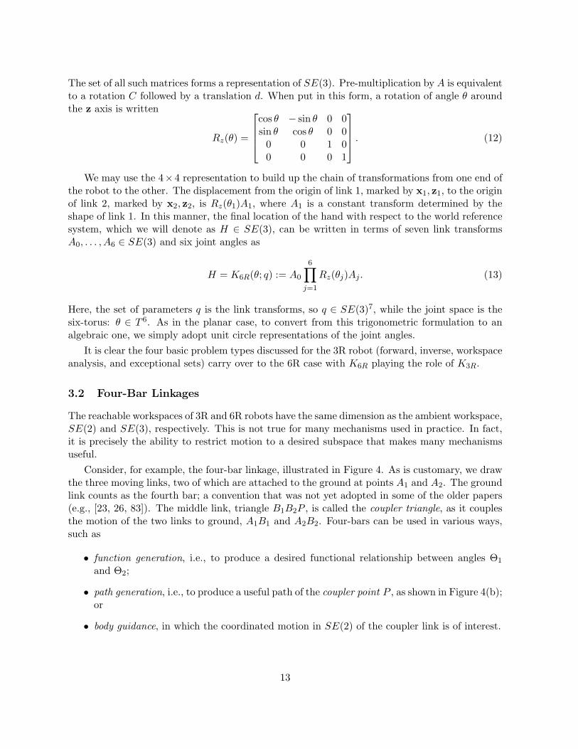
The set of all such matrices forms a representation of SE(3). Pre-multiplication by A is equivalentto a rotation C followed by a translation d. When put in this form, a rotation of angle θ aroundthe z axis is written
Rz(θ) =
cos θ − sin θ 0 0sin θ cos θ 0 00 0 1 00 0 0 1
. (12)
We may use the 4× 4 representation to build up the chain of transformations from one end ofthe robot to the other. The displacement from the origin of link 1, marked by x1, z1, to the originof link 2, marked by x2, z2, is Rz(θ1)A1, where A1 is a constant transform determined by theshape of link 1. In this manner, the final location of the hand with respect to the world referencesystem, which we will denote as H ∈ SE(3), can be written in terms of seven link transformsA0, . . . , A6 ∈ SE(3) and six joint angles as
H = K6R(θ; q) := A0
6∏j=1
Rz(θj)Aj . (13)
Here, the set of parameters q is the link transforms, so q ∈ SE(3)7, while the joint space is thesix-torus: θ ∈ T 6. As in the planar case, to convert from this trigonometric formulation to analgebraic one, we simply adopt unit circle representations of the joint angles.
It is clear the four basic problem types discussed for the 3R robot (forward, inverse, workspaceanalysis, and exceptional sets) carry over to the 6R case with K6R playing the role of K3R.
3.2 Four-Bar Linkages
The reachable workspaces of 3R and 6R robots have the same dimension as the ambient workspace,SE(2) and SE(3), respectively. This is not true for many mechanisms used in practice. In fact,it is precisely the ability to restrict motion to a desired subspace that makes many mechanismsuseful.
Consider, for example, the four-bar linkage, illustrated in Figure 4. As is customary, we drawthe three moving links, two of which are attached to the ground at points A1 and A2. The groundlink counts as the fourth bar; a convention that was not yet adopted in some of the older papers(e.g., [23, 26, 83]). The middle link, triangle B1B2P , is called the coupler triangle, as it couplesthe motion of the two links to ground, A1B1 and A2B2. Four-bars can be used in various ways,such as
• function generation, i.e., to produce a desired functional relationship between angles Θ1
and Θ2;
• path generation, i.e., to produce a useful path of the coupler point P , as shown in Figure 4(b);or
• body guidance, in which the coordinated motion in SE(2) of the coupler link is of interest.
13

A1
B1
A2
B2
P
Θ1
Θ2Φ
(a)(b)
Figure 4: Four-bar linkage.
The path of the coupler point P is called the coupler curve. In the example shown in Figure 4(b)the coupler curve has two branches; the mechanism must be disassembled and reassembled againto move from one branch to the other. (Over the complexes, the curve is one irreducible set.Whether the real coupler curve has one or two branches depends on inequality relations betweenthe link sizes.)
To specify a configuration of a four-bar, one may list the locations of the three moving linkswith respect to the ground link. That is, a configuration is a triple from SE(3)3. We may takethese as (A1,Θ1), (A2,Θ2) and (P,Φ). For generic link lengths, the mechanism has a 1DOFmotion, a curve in SE(3)3. The whole family of all possible four-bars is parameterized by theshapes of the links and the placement of the ground pivots. These add up to 9 independentparameters, which we may enumerate as follows:
• positions of ground pivots A1 and A2 in the plane (4 parameters);
• lengths |A1B1|, |A2B2|, |B1P |, and |B2P | (4 parameters); and
• angle ∠B1PB2 (1 parameter).
Clearly, the motion of a four-bar is equivalent to the self-motion of a kinematically redundantpositional 3R robot whose endpoint is at A2. The workspace regions drawn in Figure 2 nowbecome the regions within which we may place A2 without changing topology of the motion ofthe four-bar. The boundaries delineate where one or more of the angles Θ1, Θ2, and Φ changebetween being able to make full 360◦ turns or just partial turns.
As in the case of the 3R robot, we may use several different ways to write down the kinematicrelations. One particularly convenient formulation for planar mechanisms, especially those builtwith rotational joints, is called isotropic coordinates. The formulation takes advantage of the factthat a vector v = ax + by in the real Cartesian plane can be modeled as a complex numberv = a + bi. Then, vector addition, u + v, is simple addition of complex numbers, u + v, androtation of vector v by angle Θ is eiΘv.
14

Suppose that in Cartesian coordinates P = (x, y), so that the location of the coupler linkis represented by the triple (x, y,Φ), which we may view as an element of SE(2). To makethe Cartesian representation algebraic, we switch to the unit circle coordinates (x, y, cΦ, sΦ) ∈V(c2Φ + s2Φ − 1), which is an isomorphic representation of SE(3). In isotropic coordinates, therepresentation of SE(3) is (p, p, ϕ, ϕ) ∈ V(ϕϕ− 1), where
p = x+ iy, p = x− iy, ϕ = eiΦ, ϕ = e−iΦ. (14)
When (x, y,Φ) is real, we have the complex conjugate relations
p∗ = p, and ϕ∗ = ϕ, (15)
where “∗” is the conjugation operator. The isotropic coordinates are merely a linear transforma-tion of the unit-circle coordinates:[
pp
]=
[1 i1 −i
] [xy
], and
[ϕϕ
]=
[1 i1 −i
] [cΦsΦ
].
To model the four-bar linkage using isotropic coordinates, we draw a vector diagram in thecomplex plane, shown in Figure 5. Point O marks the origin, from which vectors a1 and a2 markthe fixed ground pivots and vector p indicates the current position of the coupler point. As thecoupler rotates by angle Φ, its sides rotate to ϕb1 and ϕb2, where ϕ = eiΦ. The links to groundhave lengths ℓ1 and ℓ2. Letting θj = eiΘj , j = 1, 2, we may write two vector loop equations:
ℓ1θ1 = p+ ϕb1 − a1, (16)
ℓ2θ2 = p+ ϕb2 − a2. (17)
Since a1, a2, b1, b2 are complex vectors, their isotropic representations include the conjugate quan-tities a1, a2, b1, b2, with a1 = a∗1, etc., for a real linkage. Accordingly, the vector loop equationsimply that the following conjugate vector equations must also hold:
ℓ1θ1 = p+ ϕb1 − a1, (18)
ℓ2θ2 = p+ ϕb2 − a2. (19)
Finally, we have unit length conditions for the rotations:
θ1θ1 = 1, θ2θ2 = 1, and ϕϕ = 1. (20)
Altogether, given a four-bar with the parameters a1, a1, a2, a2, b1, b1, b2, b2, ℓ1, ℓ2, we have 7 equa-tions for the 8 variables p, p, ϕ, ϕ, θ1, θ1, θ2, θ2, so we expect in the generic case that the mechanismhas a 1DOF motion.
While Eqs. 16–20 describe the complete motion of the four-bar, we might be only interestedin the path it generates. In general, in such cases we might just invoke a projection operation,
K : (p, p, ϕ, ϕ, θ1, θ1, θ2, θ2) 7→ (p, p),
15

O
p
ϕb1
ϕb2
a1
a2
ℓ1
ℓ2
Θ1
Θ2Φ
Figure 5: Vector diagram of a four-bar linkage.
and keep working with all the variables in the problem. However, in the case of the four-bar,we can easily perform the elimination operation implied by the projection. First, the rotationsassociated to Θ1 and Θ2 are eliminated as follows:
ℓ21 = (p+ ϕb1 − a1)(p+ ϕb1 − a1), (21)
ℓ22 = (p+ ϕb2 − a2)(p+ ϕb2 − a2). (22)
After expanding the right-hand sides of these and using ϕϕ = 1, one finds that the equationsare linear in ϕ, ϕ. Consequently, one may solve solve these for ϕ, ϕ using Cramer’s rule and thensubstitute the result into ϕϕ = 1 to obtain a single coupler-curve equation in just p, p. Using|α β| to denote the determinant of a 2 × 2 matrix having columns α and β, we may write thecoupler curve equations succinctly as
fcc(p, p; q) = |v u||v u|+ |u u|2 = 0, (23)
where
v =
[(p− a1)(p− a1) + b1b1 − ℓ21(p− a2)(p− a2) + b2b2 − ℓ22
], u =
[b1(p− a1)b2(p− a2)
], and u =
[b1(p− a1)b2(p− a2)
], (24)
and where q is the set of linkage parameters:
q = (a1, a2, b1, b2, a1, a2, b1, b2, ℓ1, ℓ2).
Inspection of Eqs. 23, 24 shows that the coupler curve is degree six in p, p, and in fact, thehighest exponent on p or p is three. In other words, the coupler curve is a bi-cubic sextic. Thenumber of monomials in a bi-cubic equation in two variables is 16, which is sparse comparedto the possible 28 monomials for a general sextic. The bi-cubic property implies that a couplercurve can intersect a circle in at most 6 distinct points, one of the important properties of couplercurves.
The coupler curve equation answers the workspace analysis question for four-bar path gener-ation. For example, the question of where the coupler curve crosses a given line comes down to
16

solving a sextic in one variable, a process that can be repeated for a set of parallel lines to sweepout a picture of the whole curve in the plane. (This is not the simplest procedure that can beapplied for this mechanism, but it is a workable one.)
A much tougher kind of question inverts the workspace analysis problem. These are synthesisproblems of finding four-bars whose coupler curve meets certain specifications. For example, wemight request that the coupler curve interpolate a set of points. The most extreme case is thenine-point synthesis problem of finding all four-bars whose coupler curve interpolates nine givenpoints.1 Essentially, this means solving for the parameters q that satisfy the system:
fcc(pj , pj ; q) = 0, j = 0, . . . , 8, (25)
for nine given points (pj , pj) ∈ C2, j = 0, . . . , 8. This problem, first posed in 1923 by Alt [4], finallysuccumbed to solution by polynomial continuation in 1992 [113, 114], where it was demonstratedthat 1442 coupler curves interpolate a generic set of nine points, each coupler curve generated bythree cognate linkages (Robert’s cognates [83]).
The system of Eq. 25 consists of nine polynomials of degree eight. Roth and Freudenstein [85]formulated the problem in a similar way, but ended up with eight polynomials of degree seven.Since this version has become one of our test problems, we give a quick re-derivation of it here.The key observation is that since we are given the nine points, we may choose the origin ofcoordinates to coincide with the first one: (p0, p0) = (0, 0). Moreover, the initial rotations ofthe links can be absorbed into the link parameters, so we may assume that Θ1,Θ2,Φ = 0 at theinitial precision point. Accordingly, at that point Eqs. 21,22 become
ℓ21 = (b1 − a1)(b1 − a1), (26)
ℓ22 = (b2 − a2)(b2 − a2). (27)
Substituting from these into the expression for v in Eq. 24, one may eliminate ℓ21 and ℓ22. Accord-ingly, the Roth-Freudenstein formulation of the nine-point problem is
fcc(pj , pj ; q) = 0, j = 1, . . . , 8, (28)
with the precision points (pj , pj) given and with variables a1, a2, b1, b2, a1, a2, b1, b2. Althoughthe equations appear to be degree eight, the highest degree terms all cancel, so the equations areactually degree seven. Hence, the total degree of the system is 78. The original Roth-Freudensteinformulation did not use isotropic coordinates, but their equations are essentially equivalent to theones presented here.
Various other synthesis problems can be posed to solve engineering design problems. Thenature of the synthesis problem depends on the use to which the linkage is being applied. Forexample, if the four-bar is being used for function generation, one may seek those mechanismswhose motion interpolates angle pairs (Θ1,j ,Θ2,j) ∈ R2 (for up to five such pairs). For bodyguidance, one may specify triples (pj , pj ,Φj) ∈ SE(2) for up to five poses. Instead of justinterpolating points, synthesis problems can also include derivative specifications (points plus
1Nine is the maximum possible number of generic points that can be interpolated exactly, because that is thenumber of independent parameters. Although we have 10 parameters in q, there is a one-dimensional equivalenceclass. This could be modded out by requiring that b1 be real, i.e., b1 = b1. We enumerated a count of nineindependent parameters earlier in this section.
17

tangents). Kinematicians sometimes distinguish between these as “finitely separated” versus“infinitesimally separated” precision points. Every synthesis problem has a maximum number ofprecision points that can be exactly interpolated. If more points are specified, one may switchfrom exact synthesis to approximate synthesis, in which one seeks mechanisms that minimize asum of squares or other measure of error between the generated motion and the specified points.
While this subsection has focused on the four-bar planar linkage, it should be appreciatedthat similar questions will arise for other arrangements of links and joints, and like the 6R spatialgeneralization of the 3R planar robot, some of these move out of the plane into three-space.
3.3 Platform Robots
Suppose you are given the task of picking up a long bar and moving it accurately through space.While it may be possible to do so by holding the bar with one hand, for a more accurate motion,one naturally grasps it with two hands spread a comfortable distance apart. This reduces themoments that must be supported in one’s joints. On the down side, a two-hand grasp limits therange of motion of the bar relative to one’s body due to the finite length of one’s arms.
Similar considerations have led engineers to develop robotic mechanisms where multiple chainsof links operate in parallel to move a common end-effector. Generally, this enhances the robot’sability to support large moments, but this comes at the cost of a smaller workspace than is attainedby a serial-link robot of similar size. While many useful arrangements have been developed, wewill concentrate on two “platform robots”: one planar and one spatial. In each case, a movingend-effector link is supported from a stationary base link by several “legs” having telescoping leglengths. As SE(2) and SE(3) are 3- and 6-dimensional, respectively, it turns out that the numberof legs that make the most useful mechanisms is also 3 and 6, respectively. We begin with theplanar 3-RPR platform robot and then address the related 6-SPS spatial platform robot. (Thesenotations will be explained shortly.)
3.3.1 3-RPR Planar Robot
Recall that R indicates a rotational joint and P indicates a prismatic joint. An RPR chain is aset of four links in series where links 1 and 2 are connected by an R joint, 2 and 3 by a P joint,and 3 and 4 by another R joint. A 3-RPR planar robot has three such chains wherein the firstand last links are common to all three chains. This arrangement is illustrated in Figure 7(a).
Before working further with the 3-RPR robot, we first consider what happens to a four-barlinkage if we add a fifth link between its coupler point and a new ground pivot, A3, as shown inFigure 6(a). As it has five links, this new linkage is known as the pentad linkage. Due to thenew constraint imposed on the motion of P by the link A3P , the pentad becomes an immobilestructure. The possible assembly configurations can be found by intersecting the four-bar couplercurve (branches C1 and C2) that we first met in Figure 4(b) with the circle C3 centered on A3 withradius |AP |. As shown in Figure 6(b), this particular example has six real points of intersection,one of which gives the illustrated configuration. We already noted in the previous section thatdue to the bi-cubic nature of the coupler curve, there are generically six such intersection pointsover the complexes. In this example all of them are real.
The pentad could be called a 3-RR mechanism, as the three links (legs) between ground and
18

A1
B1
A2
B2
P
A3
(a)
C1
C2 C3
(b)
Figure 6: Pentad (3-RR) linkage.
ℓ1
ℓ2
ℓ3
P
Φ
(a)O
p
ϕb1
ϕb2
a1
a2
a3ℓ1
ℓ2
ℓ3
Θ1
Θ2
Θ3
Φ
(b)
Figure 7: 3-RPR planar platform robot.
the coupler triangle have R joints at each end. If we add “prismatic” slider joints on each leg,it becomes the 3-RPR platform robot shown in Figure 7(a). The prismatic joints allow the leglengths ℓ1, ℓ2, ℓ3 to extend and retract, driven by screws or by hydraulic cylinders. Thus, theinput to the robot are the three leg lengths (ℓ1, ℓ2, ℓ3) ∈ R3, and the output is the location of thecoupler triangle, a point in SE(2).
We have already done most of the work for analyzing the 3-RPR robot when we formulatedequations for the four-bar linkage. The vector diagram in Figure 7(b) is identical to Figure 5except for the addition of vector a3 to the new ground pivot and the new link length ℓ3. Usingthe same conventions for isotropic coordinates as before, we simply add the new equations
ℓ3θ3 = p− a3, ℓ3θ3 = p− a3, and θ3θ3 = 1. (29)
If we wish to eliminate Θ3, we replace these with the circle equation
ℓ23 = (p− a3)(p− a3). (30)
19

The inverse kinematics problem is to find the leg lengths (ℓ1, ℓ2, ℓ3) given a desired locationof the coupler triangle (p, p, ϕ, ϕ) ∈ SE(2). Since the leg lengths must be positive, they can beevaluated uniquely from Eqs. 21,22,30.
In the opposite direction, the forward kinematics problem comes down to computing thesimultaneous solution of Eqs. 23 and 30. This is the same as solving the pentad problem illustratedin Figure 6(b), which has up to six distinct solutions. Notice that once we have found (p, p) fromthis intersection, we may recover (ϕ, ϕ) from Eqs. 21,22, where they appear linearly. Using thenotation of Eq. 24 for 2× 2 determinants, this solution reads
ϕ = |u v|/|u u|, ϕ = |v u|/|u u|. (31)
3.3.2 6-SPS “Stewart-Gough” Platform
A natural generalization of the 3-RPR planar platform robot is the 6-SPS spatial platform robot,where the rotational R joints are replaced by spherical S joints and the number of legs is increasedto six. This arrangement, illustrated in Figure 8, is usually referred to as a “Stewart-Gough2
platform.” The device has a stationary base A and a moving platform B connected by six legsof variable length. The six legs acting in parallel can support large forces and moments, whichmakes the platform robot ideal as the motion base for aircraft simulators, although it has manyother uses as well.
Most practical versions of the device resemble the arrangement shown in Figure 9, where thesix joints on the base coincide in pairs, forming a triangle, and those on the moving platformare arranged similarly. The edges of these triangles along with the six connecting legs form thetwelve edges of an octahedron. In more general arrangements, such as the one shown in Figure 8,the joints have no special geometric configuration.
It is easy to see that if the legs of the platform are allowed to extend and retract freelywithout limit, the moving platform can be placed in any pose, say (p, C) ∈ SE(3), where p ∈ R3
is the position of a reference point on the platform and C ∈ SO(3) is a 3× 3 orthogonal matrixrepresenting the orientation of the platform. Let aj ∈ R3, j = 1, . . . , 6 be vectors in referenceframe A to the centers A1, . . . , A6 of the spherical joints in the base, and let bj ∈ R3, 1, . . . , 6be the corresponding vectors in reference frame B for the joint centers B1, . . . , B6 in the movingplatform. Figure 8 labels the joints and joint vectors for leg 1. The length of the jth leg, denotedLj is just the distance between its joint centers:
L2j = |AjBj |2 = ||p+ Cbj − aj ||22= (p+ Cbj − aj)
T (p+ Cbj − aj), j = 1, . . . , 6. (32)
This spatial analog to Eqs. 21,22 solves the inverse kinematic problem for the 6-SPS robot. Thereis only one inverse solution having all positive leg lengths.
Another way to view Eq. 32 is that when leg length Lj is locked, it places one constraint onthe moving platform: joint center Bj must lie on a sphere of radius Lj centered on joint center
2For historical reasons, the arrangement first became widely known as a Stewart platform, although D. Stewart’sinvention actually had a different design. As it appears that E. Gough was the true first inventor of the device,current usage [19] now credits both contributors.
20

p
A
B
L1
a1
b1
B1
A1
Figure 8: General Stewart-Gough platform robot
Figure 9: Octahedral Stewart-Gough platform robot
21

Aj . Since SE(3) is six-dimensional, it takes six such constraints to immobilize plate B, turningthe robot into a 6-SS structure. The forward kinematics problem is to find the location of Bgiven the six leg lengths, that is, to solve the system of Eqs. 32 for (p, C) ∈ SE(3) given the leglengths (L1, . . . , L6) and the parameters of the platform (aj ,bj), j = 1, . . . , 6.
Notice that for the platform robots, the inverse kinematics problem is easy, having a uniqueanswer, while the forward kinematics problem is more challenging, having multiple solutions.This is the opposite of the situation for serial-link robots. It can happen that both directions arehard; for example, consider replacing the simple SPS-type legs of the Stewart-Gough platformwith ones of type 5R.
It is somewhat inconvenient to solve the forward kinematics problem as posed in Eq. 32,because we must additionally impose the conditions for C to be in SO(3), namely CTC =I and detC = 1. In the planar 3-RR case, isotropic coordinates simplified the treatment ofdisplacements in SE(2). Although isotropic coordinates do not generalize directly to SE(3), thereis an alternative applicable to the spatial case: Study coordinates. Just as isotropic coordinates(p, p, ϕ, ϕ) ∈ C4 are restricted to the bilinear quadric ϕϕ = 1, Study coordinates [e, g] ∈ P7 arerestricted to the bilinear quadric S2
6 = V(Q), where
Q(e, g) = eT g = e0g0 + e1g1 + e2g2 + e3g3 = 0. (33)
The isomorphic mapping between Study coordinates [e, g] ∈ S26 ⊂ P7 and (p, C) ∈ C3 × SO(3)
is discussed in Appendix A. In Study coordinates, translation p is rewritten in terms of [e, g]via quaternion multiplication and conjugation as p = g ∗ e′/(e ∗ e′) while rotation of vector v byrotation matrix C is rewritten as Cv = e ∗ v ∗ e′/(e ∗ e′).
In Study coordinates, the leg length equations become:
L2i = ||(g ∗ e′ + e ∗ bj ∗ e′)/(e ∗ e′)− aj ||22, j = 1, . . . , 6. (34)
Using the relations ||v||2 = v ∗ v′, and (a ∗ b)′ = b′ ∗ a′, one may expand and simplify Eq. 34 torewrite it as
0 = g ∗ g′ + (bj ∗ b′j + aj ∗ a′j − L2
j )e ∗ e′ + (g ∗ b′j ∗ e′ + e ∗ bj ∗ g′)
− (g ∗ e′ ∗ a′j + aj ∗ e ∗ g′)− (e ∗ bj ∗ e′ ∗ a′j + aj ∗ e ∗ b′j ∗ e′)
= gT g + gTBje+ eTAje, j = 1, . . . , 6.
(35)
In the last expression, g and e are treated as 4×1 matrices and the 4×4 matrices Aj (symmetric)and Bj (antisymmetric) contain entries that are quadratic in aj , bj , Lj . Expressions for Aj andBj can be found in [112]. In the forward kinematics problem, Aj and Bj are considered known,so these equations along with the Study quadric equation, Eq. 33, are a system of seven quadricson P7. The forward kinematics problem is to solve these for [e, g] ∈ P7 given the leg lengths(L1, . . . , L6).
The forward kinematics problem for general Stewart-Gough platforms received extensive aca-demic attention leading up to its effective solution in the early 1990s. It can be shown that ageneric instance of the problem has 40 isolated solutions in complex P7. The first demonstrationof this was numerical, based on polynomial continuation [81, 82], while around the same timeothers published demonstrations based on Grobner bases over a finite field [59, 78] and a proof
22

by abstract algebraic geometry [84]. The formulation of the problem in Study coordinates wasarrived at independently by Wampler [112], who gave a simple proof of the root count of 40, andHusty [50], who showed how to reduce the system to a single degree 40 equation in one variable.Using current tools in numerical algebraic geometry, the solution of seven quadrics is a simpleexercise, requiring from a few seconds to a minute or so of computational time, depending on thecomputer applied to the task, to track 27 homotopy paths. As we shall discuss further below,once the first general example has been solved to find just 40 solutions, all subsequent examplescan be solved by tracking only 40 homotopy paths.
4 Algebraic Kinematics
Now that we have discussed a variety of problems from kinematics, let us examine how we mayfit them all into a common framework. This framework will help show why so many problems inkinematics are algebraic at their core.
4.1 Rigid-Body Motion Spaces
In the examples, we have already dealt in some detail with SE(3), the six-dimensional set of rigid-body transformations in three-space. The most useful representations of SE(3) are as follows.
• (p, C) ∈ R3 × SO(3), where SO(3) = {C ∈ R3×3 | CTC = I, detC = 1}. This acts on avector v ∈ R3 to transform it to u = Cv + p.
• The 4 × 4 homogeneous transform version of this, where (p, C) are placed in a matrix sothat the transform operation becomes[
u1
]=
[C p0 1
] [v1
].
• Study coordinates [e, g] ∈ S26 ⊂ P7, where S2
6 = V(eT g) and the transform operation is
u = (e ∗ v ∗ e′ + g ∗ e′)/(e ∗ e′).
In all three cases, the representations live on an algebraic set and the transform operation is alsoalgebraic.
There are several subgroups of SE(3) that are of interest. Most prominent is SE(2), the setof planar rigid-body transformations, with representations as follows.
• (p, C) ∈ R2 × SO(2), where SO(2) = {C ∈ R2×2 | CTC = I, detC = 1}. The transformrule looks identical to the spatial case: u = Cv + p.
• The unit-circle form {(x, y, s, c) ∈ R4 | c2 + s2 = 1}. This is the same as the former withp = xi+ yj and
C =
[c −ss c
].
23

• The tangent half-angle form (x, y, t) ∈ R3, in which rotations become
C =1
1 + t2
[1− t2 −2t2t 1− t2
].
• Isotropic coordinates {(p, p, θ, θ) ∈ C4 | θθ = 1}. Real transforms must satisfy p∗ = p andθ∗ = θ. The action of transform (p, p, θ, θ) on a vector given by isotropic coordinates (v, v)is the vector (u, u) given by
(u, u) = (p+ θv, p+ θv).
Again, each of these representations lives on an algebraic set and has an algebraic transformoperation. Clearly, SE(2) is a three-dimensional space.
Another subspace of interest is the set of spherical transforms, that is, just SO(3), anotherthree-dimensional space. This is SE(3) with the translational portion set identically to zero. Theterminology “spherical” derives from the fact that this is the set of motions allowed by a sphericalball set in a spherical socket of the same diameter.
At root, all of these are algebraic because an essential property of a rigid body transform is thepreservation of distance between any two points. Squared distances are, of course, algebraic. Thesecond property is that the transform must preserve handedness, as we do not wish to transmute arigid body into its mirror image. It is this latter consideration that restricts the rotational portionto SO(3), which is the component of the set of all orthogonal matrices, O(3), that contains theidentity matrix.
4.2 Algebraic Joints
A mechanism is a collection of rigid bodies connected by joints. Without the joints, each bodycould move with six degrees of freedom anywhere in SE(3). Typically, we declare one body tobe “ground” and measure the locations of all the other bodies relative to it, so a collection ofn bodies lives in SE(3)n−1. Joints are surfaces of contact between bodies that constrain themotion of the mechanism to a subset of SE(3)n−1. Algebraic joints are those which constrain amechanism to algebraic subsets of SE(3)n−1.
The most important joints for building mechanisms are the lower-order pairs. These arepairs of identical surfaces that can stay in full contact while still allowing relative motion. Inother words, they are formed by a surface that is invariant under certain continuous sets ofdisplacements. The lower-order pairs form six possible joint types, having the following standardsymbols.
R “Revolute.” A surface of revolution is invariant under rotation about its axis of symmetry. Ageneral R pair allows a 1DOF rotational motion equivalent to SO(2). An example is a doorhinge.
P “Prismatic.” A surface swept out by translating a planar curve along a line out of its plane.A general P pair allows a 1DOF translational motion. An example is a square peg in amatching square hole.
24

H “Helical,” also known as a “screw joint.” A surface swept out by a curve that simultaneouslyrotates and translates about a fixed axis, with the two rates in fixed proportion. This yieldsa 1DOF motion for a general H pair. The ratio of the linear rate to the rotational rate iscalled the “pitch” of the screw. An example is a nut on a screw.
C “Cylindrical.” A round peg in a matching round hole can both rotate around the axis ofsymmetry and translate along it independently, generating a 2DOF motion.
E “Plane,” from the German “ebener” since P is already taken. Plane-to-plane contact allows a3DOF motion, namely the set SE(2).
S “Spherical.” A spherical ball in a matching spherical socket allows a 3DOF motion, the setSO(3).
The importance of the lower-order pairs derives from the fact that surface-to-surface contactspreads forces of contact over a larger area, reducing stresses that might wear out the machinery.
Fortunately – from the viewpoint of an algebraic geometer – five of these six joint types arealgebraic. The exception is the H joint. The relative motion of a helical joint of pitch ρ with axisthrough the origin along the z direction is given by 4× 4 transforms of the form
cos θ − sin θ 0 0sin θ cos θ 0 00 0 1 ρθ0 0 0 1
. (36)
The mixture of θ with cos θ and sin θ makes the motion truly trigonometric, hence non-algebraic.An alternative line of reasoning is to observe that a helix and a plane containing its symmetryaxis intersect in an infinite number of isolated points. Any algebraic curve in R3 intersects aplane in at most a finite number of isolated points.
Even more fortuitously, helical joints are rarely used as a direct motion constraint in a mannerthat impacts kinematic analysis. Instead, screws are usually used to transmit power along aprismatic joint. Consequently, the geometric motion of a great many mechanisms is governed byalgebraic joints.
Not all joints in mechanism work are lower-order pairs. Line contact between two surfaces canbe adequate to spread stresses, and it is typical of many rolling contacts (e.g., wheel on plane).With sufficient lubrication, even sliding line contacts can endure, such as happens in some camcontacts.
To demonstrate that a joint type is algebraic, one may write down the constraint conditions itimposes between the transforms for the two bodies in contact. Suppose (p1, C1), (p2, C2) ∈ SE(3)are the rigid-body transforms for bodies 1 and 2. To impose constraints equivalent to the lower-order joints, we need to specify geometric features that are associated with the joints. To thisend, let a be a point of body 1, given in body 1 coordinates. The world coordinates of the pointare then a = p1 + C1a. Similarly, let b be a point in body 2, so that its world coordinates areb = p2+C2b. Let (u1,u2,u3) be a dextral set of mutually orthogonal unit vectors in body 1, thatis, the matrix formed with these as its column vectors is in SO(3). Let (v1,v2) be orthogonal unitvectors in body 2. The unit vectors transform into world coordinates as ui = C1ui, i = 1, 2, 3,
25

and vi = C2vi, i = 1, 2. With these features, the constraints imposed by lower-order pairs R,P, C, E, and S can be modeled with equations that are algebraic in the transforms (p1, C1) and(p2, C2) and the features a,b,u1,u2,u3,v1,v2 as follows.
R: a = b and u1 = v1, which after substituting from the expressions above become
p1 + C1a = p2 + C2b, and C1u1 = C2v1.
For brevity, in the remaining cases we only give the constraints on the world coordinates, whichthe reader may easily expand to get equations in the transforms and features.
P: uT2 (b− a) = 0, uT
3 (b− a) = 0,u1 = v1, u2 = v2.
C: uT2 (b− a) = 0, uT
3 (b− a) = 0,u1 = v1
E: uT1 (b− a) = 0, u1 = v1.
S: a = b.
Equating two points imposes three constraints, whereas equating two unit vectors imposes onlytwo independent constraints. From this, we see that the R joint imposes 5 constraints, the C jointimposes 4, and the E and S joints each impose 3 constraints. For the P joint, we are equatinga pair of orthogonal unit vectors to another such pair, which together imposes three constraints.With the other two scalar equations, this brings the total number of constraints imposed by a Pjoint to 5. These models are not minimal with respect to the number of parameters involved, soin practice we usually write down equations in other ways.3 Nevertheless, this suffices to showthat the lower-order pairs R, P, C, E, and S are, indeed, algebraic.
Joints can be described either extrinsically in terms of the constraints they impose or in-trinsically in terms of the freedoms they allow. The foregoing description is extrinsic. We havealready seen how to model R joints intrinsically in the discussion of spatial 6R serial-link robots(see § 3.1.2). Note that this was written in terms of 4× 4 transforms Rz(θ) from Eq. 12, which isequivalent to the transform for a helical joint in Eq. 36 with zero pitch, ρ = 0. The lower-orderpairs can be modeled intrinsically using matrices of the form
cos θ − sin θ 0 asin θ cos θ 0 b0 0 1 c0 0 0 1
. (37)
R: Use (37) with a = b = c = 0, leaving θ as the joint variable.
P: Use (37) with θ = a = b = 0, leaving c as the joint variable.
C: Use (37) with a = b = 0, leaving θ and c both as joint variables.
E: Use (37) with c = 0, leaving θ, a, and b all as joint variables.
3The Denavit-Hartenberg formalism is a minimal parameterization. See [68] or any modern kinematics textbookfor a definition.
26

R P C E Sconstraints 5 5 4 3 3freedoms 1 1 2 3 3
Table 1: Algebraic lower-order pairs: constraints and freedoms
S: Use [C 00 1
]with C ∈ SO(3) as the joint freedom.
In an intrinsic formulation, the link geometry is encoded in link transforms that are interposedbetween the joints, such as the matrices Aj in the formulation of the 6R kinematics in § 3.1.2.
If c is the number of independent constraints imposed by a joint, then the number of freedomsof body 2 relative to body 1 allowed by the joint is 6−c, as summarized in Table 1. When modelingthe joints with a low number of freedoms (R, P, C) it is usually more convenient to use an intrinsicformulation, while S joints are best modeled extrinsically.
4.3 Mechanism Types, Families, and Spaces
To fit a wide variety of kinematics problems into a common format, we need the definitions of amechanism type and a mechanism family.
Definition 4.1 A mechanism type is defined by the number of links, nL, and a symmetric nL×nL
adjacency matrix T whose (i, j)th element denotes the type of joint between links i and j, one ofR, P, H, C, E, S, or ∅, where ∅ indicates no connection. By convention, all diagonal elementsare ∅.
(Each joint appears twice in the matrix: Ti,j = Tj,i are the same joint.) We assume here thatthe joints are limited to the lower-order pairs, but the list of possibilities could be extended.The enumeration of all possible mechanism types for each value of nL without double-countingmechanisms that are isomorphic under renumbering of the links is a problem in discrete math-ematics. Choosing a prospective mechanism type is the first step in a mechanism design effort,and methods for guiding the enumeration of promising alternatives fall into the category of typesynthesis. In this paper, we assume that this crucial step is already done so that we begin witha mechanism type.
Each mechanism type has an associated parameter space. We have seen in § 4.2 one way tomodel each of the algebraic lower-order pairs, R, P, C, E, and S, in terms of feature points andunit vectors. The cross-product space of all these geometric features forms a universal parameterspace for the mechanism type. One may choose to model the joints in a more parsimonious way,but we assume that in the alternative model there still exists a parameterization for each jointand an associated parameter space for all the joints taken together.
Definition 4.2 A universal mechanism family (T,Q) is a mechanism type T with an associatedparameter space Q describing the geometry of the joints. We assume that Q is irreducible.
27

If one has a parameter space Q that is not irreducible, each irreducible component should beconsidered to define a separate universal mechanism family.
Definition 4.3 A mechanism family (T,Q′) is a subset of a universal mechanism family (T,Q)restricted to an irreducible algebraic subset Q′ ⊂ Q.
Examples of the common sorts of algebraic restrictions that define a mechanism family includethe condition that the axes of two R joints in a certain link must be parallel, perpendicular,or intersecting, etc. As a particular example, consider that the universal family of spatial 3Rserial-link chains includes the family of 3R planar robots of § 3.1.1 wherein the R joints are allparallel. One should appreciate that there can be subfamilies within families, and so on.
For certain mechanisms, all points of the links move in parallel planes, hence the links movein SE(2) and the mechanism is said to be planar. In particular, a mechanism family whereinall joints are either rotational R with axis parallel to the z-direction or prismatic P with axisperpendicular to the z-direction is planar.
Definition 4.4 The link space Z for an n link mechanism is SE(3)n−1, where one of the linksis designated as ground (p, C) = (0, I). Any of the isomorphic representations of SE(3) from§ 4.1 can be used as models of SE(3). If the mechanism family is planar, then Z = SE(2)n−1 inany of its isomorphic representations from § 4.1.
Definition 4.5 The mechanism space M of a mechanism family (T,Q) is the subset of Z × Qthat satisfies the joint constraints.
Proposition 4.1 If a mechanism family is built with only the algebraic joints R, P, C, E, andS, then its mechanism space is algebraic.
Proof. Section 4.1 with Appendix A shows that Z is algebraic and Q is algebraic by assumption.That is, Z and Q are sets defined by algebraic equations. Section 4.2 shows that the algebraicjoints impose algebraic constraints on the coordinates of Z and Q, and hence all the definingequations for M are algebraic. 2
Definition 4.6 A mechanism is a member of a mechanism family (T,Q) given by a set of pa-rameters q ∈ Q.
4.4 Kinematic Problems in a Nutshell
In this section, we present an abstract formulation that summarizes all the main types of geometricproblems that arise in kinematics. In the next section, we will discuss more concretely how tomap a mechanism into this formulation.
The key to our formulation is the following diagram:
X� JM -K
Y
Q?
πM������
X ×Q
J HHHHHjY ×Q
K6π1
π2
6π4
π3- �
(38)
28

The main elements of the diagram are four sets X,M, Y,Q and three maps J,K, πM . The foursets are as follows.
• X is the input space of the mechanism. In robotics, it is usually called the “joint space.”Its coordinates are typically quantities that we command by controlling motors or otheractuators.
• Y is the output space, often called the “operational space” in robotics. Its coordinates arethe final output(s) we wish to obtain from the mechanism, such as the location of a robot’shand.
• Q is the parameter space of a family of mechanisms. It is the set of parameters necessaryto describe the geometry of the joints in each link. Each point in Q is therefore a specificmechanism with designated link lengths, etc. The whole set Q constitutes a family ofmechanisms, such as the set of all 6R robot arms, with the coordinates of Q representing allpossible link lengths, etc. We assume that Q is an irreducible algebraic subset of some Cm,that is, it is an irreducible component of V(G) for some system of analytic functions G :Cm → Cm′
. If V(G) has more than one irreducible component, then each such componentis considered a different family of mechanisms.
• M is the mechanism space, which describes all possible configurations of the mechanismfor all possible parameters. Let Z be the space of all possible locations of the links whenthey are disconnected. That is, for an N -link spatial mechanism with one link designated asground, Z = SE(3)N−1. Then, M is the subset of Z×Q where the link locations satisfy theconstraints imposed by the joints between them. Let F : Z×Q → Cc be a set of polynomialsdefining the joint constraints. Then, M = V(F )∩V(G) is an extrinsic representation of M .Each point (z, q) ∈ M is a specific mechanism q ∈ Q in one of its assembly configurationsz ∈ Z. In some cases, it is more natural to describe M intrinsically via an irreducible set,say Θ, that parameterizes the freedoms of the joints of the mechanism, so that Z becomesΘ × SE(3)N−1. We will use this, for example, to describe M for 6R serial-link robots.In such a representation, F includes the equations that define Θ along with the equationsrelating link poses to joint freedoms and equations for the constraints imposed by closingkinematic loops. Formulating such equations is part of the art of kinematics, and we willnot delve into it in this paper beyond what is necessary to present specific examples.
After choosing a representation for SE(3), and if present, for the joint freedom space Θ, the spaceZ is a subspace of some Euclidean space, Z ⊂ Cν , and z ∈ Z has coordinates z = (z1, . . . , zν).
Three maps are defined on M , as follows.
• J : M → X is the input map, which extracts from M the input values. The symbol Jacknowledges that the inputs are usually a set of joint displacements.
• K : M → Y is the output map, which extracts from M the output values.
• πM : M → Q is a projection that extracts the parameters from M . It is the naturalprojection operator on Z ×Q restricted to M given by πM : (z, q) 7→ q.
29

For the moment, we assume only that F,G, J,K are analytic so that the spaces X,M, Y areanalytic sets. Although later we will restrict further to algebraic maps and algebraic sets, theanalytic setting allows a somewhat wider range of mechanisms into the framework. Specifically,H joints are analytic but not algebraic.
The commutative diagram is completed by defining J := (J, πM ) and K := (K,πM ) and theassociated natural projections π1, π2, π3, π4.
It should be understood that M characterizes a family of mechanisms, such as the familyof spatial 6R serial-link robots, the family of planar four-bar linkages, or the family of Stewart-Gough platforms. Maps J and K are tailored to an application of the mechanism. For a four-barfunction generator, J gives the input angle and K gives the output angle, while for a four-barpath generator, K gives instead the position of the coupler point.
Using the diagram of Eq. 38, we may succinctly recast all the problems mentioned in themotivating examples of § 3. The problems broadly classified into three types of problems:
• Analysis (mobility analysis, forward and inverse kinematics, workspace analysis),
• Synthesis (precision point problems), and
• Exceptional mechanisms.
We describe each of these in more detail next.
4.4.1 Analysis
In analysis problems, one has a specific mechanism, say q∗ ∈ Q, and one wishes to analyze someaspect of its motion.
Definition 4.7 The motion of a mechanism given by parameters q∗ ∈ Q in a family with mech-anism space M is π−1
M (q∗) = M ∩ V(q − q∗) where (z, q) are coordinates in Z ×Q. This can alsobe called the motion fiber over q∗.
In the following, it is also convenient to define the inverses of J and K:
J−1(x) = {(z, q) ∈ M | J(z, q) = x}, K−1(y) = {(z, q) ∈ M | K(z, q) = y}.
These are defined for x ∈ X and y ∈ Y , respectively. In the set J−1(x) for a particular x ∈ X, qis not fixed, so this inverse applies across a whole mechanism family. When we wish to addressjust one particular mechanism, q∗, we want to consider the inverse of J instead:
J−1(x, q∗) = {(z, q) ∈ M | J(z, q) = (x, q∗)}.
Similarly, we have:K−1(y, q∗) = {(z, q) ∈ M | K(z, q) = (y, q∗)}.
The basic problems in analysis are as follows.
30

• Motion decomposition of a mechanism breaks π−1M (q∗) into its irreducible components,
often called assembly modes by kinematicians. (See § 7 for a description of irreducible com-ponents.) The numerical irreducible decomposition of π−1
M (q∗) (§ 7.5) finds the dimensionand degree of each assembly mode and provides a set of witness points on each.
• Motion decomposition of a mechanism family breaks M into its irreducible components.If A ⊂ M is one of these components, then πM (A) ⊂ Q is the subfamily of mechanismsthat can be assembled in that mode, dimπM (A) is the dimension of the subfamily, anddimA− dimπM (A) is the mobility of that mode.
• Mobility analysis seeks to find the degrees of freedom (DOFs) of the mechanism, whichis equivalent to
Mobility := dimπ−1M (q∗). (39)
As the dimension of an algebraic set is always taken to be the largest dimension of any ofits components, this definition of mobility picks out the assembly mode (or modes) havingthe largest number of DOFs. There are simple formulas, known as the Gruebler-Kutzbachformulas, that correctly estimate the mobility for a wide range of mechanisms, and evenmore mechanisms submit to refined analysis based on displacement group theory, but thereexist so-called “paradoxical” mechanisms that have higher mobility than these methodspredict. To handle all cases, one needs to analyze the equations defining M in more detailtaking into account that q∗ may be on a subset of Q having exceptional mobility.
• Local mobility analysis finds the mobility of a mechanism in a given assembly configu-ration. That is, given (z∗, q∗) ∈ Z ×Q, one wishes to find
Local mobility := dim(z∗,q∗) π−1M (q∗). (40)
A mechanism can have more than one assembly mode, corresponding to the irreduciblecomponents of π−1
M (q∗). The local mobility is the dimension of the assembly mode thatcontains the given configuration, z∗, or if there is more than one such mode, the largestdimension among these.
• Forward kinematics seeks to find the output that corresponds to a given input x∗ for amechanism q∗. That is, for x∗ ∈ X and q∗ ∈ Q, one wishes to find
FK(x∗, q∗) := K(J−1(x∗, q∗)). (41)
Example: given the joint angles of a particular 6R serial-link robot, find its hand pose.
• Inverse kinematics is similar to forward kinematics but goes from output to input. Fory∗ ∈ Y and q∗ ∈ Q find
IK(y∗, q∗) := J(K−1(y∗, q∗)). (42)
Example: given the hand pose of a particular 6R serial-link robot, find all sets of jointangles that reach that pose.
• Singularity analysis finds configurations where the maps lose rank. If we have found amotion decomposition of the mechanism, then for each assembly mode A ⊂ π−1
M (q∗) there
31

is an associated input space J(A) and an output space K(A). The input and output mapshave Jacobian matrices ∂J/∂z and ∂K/∂z. Assume for the moment that A is a reducedalgebraic set. (For example, V(x− y) is a reduced line in the (x, y)-plane, while the doubleline V((x− y)2) is non-reduced.) For generic points (z, q∗) ∈ A, the Jacobian matrices havea constant rank, say rank[∂J/∂z(z, q∗)] = rJ and rank[∂K/∂z(z, q∗)] = rK . Then, theremay be input and output singularities, as follows.
Input Singularities: {(z, q∗) ∈ A | rank ∂J∂z (z, q
∗) < rJ}. In the common case that ∂J/∂zis square and generically full rank, these are the special configurations where, to firstorder, the mechanism can move without any change in its input.
Output Singularities: {(z, q∗) ∈ A | rank ∂K∂z (z, q
∗) < rK}. In the common case that∂K/∂z is square and generically full rank, these are the special configurations where,to first order, the mechanism can move without any change in its output.
If A is a non-reduced assembly mode, a kinematician might consider the whole set to besingular, as the defining equations for A are degenerate in the sense that the column rankof the Jacobian for the system of equations that define π−1
M (q∗) is less than the codimensionof the set A. Alternatively, one might wish to consider the input and output singularities ofthe reduction of A, which can be analyzed via a deflation of A. (See § 6.3 for a discussionof deflation.)
• Workspace analysis seeks to find all possible outputs of a robot or mechanism. Ignoringlimits on the inputs, this is just the setK(π−1
M (q∗)). The main concern in practice is the set ofoutputs for real assembly configurations, so letting AR denote the real points in an assemblymode A, the corresponding workspace is K(AR). As we discussed in § 3.1.1, the boundariesof the real workspace K(AR) are given by the real output singularities. When joint limitsare included, these may also induce boundaries in the workspace. If B ⊂ X is a joint limitboundary, then K(J−1(B)∩π−1
M (q∗)) may form part of the workspace boundary. Positionalworkspaces and orientational workspaces fit into the same picture by reformulating K tooutput just position or orientation.
Example 1: for a 6R serial-link robot, find all possible poses that the hand can reach.
Example 2: for a given four-bar linkage with output defined as the position of its couplerpoint, find the coupler curve.
Example 3: for a 6-SPS (Stewart-Gough) platform robot with limits on the leg lengths, findall possible poses of the moving platform.
The motion of a mechanism over the complexes contains its real motion, but the extraction ofthe real motion from the complex one can be difficult, all the more so as the dimensionality of themotion grows. See § 11 for a discussion. The real motion may break up into smaller pieces thanthe complex one: for example, the coupler curve illustrated in Figure 4(b) has two real branchesbut they both belong to the same irreducible curve in the complexes. Some branches of a realmotion may even have a smaller dimension than the complex motion that contains them. See[115] for further discussion.
The problems presented above mainly concern the geometry of a mechanism’s motion, whereprincipally angles, positions, and poses enter the picture. As indicated by the questions of sin-
32

gularity analysis, one may also be concerned with differential relations between these, so thatjoint rates, linear velocity, and angular velocity may become objects of study, as might quantitiesrelated to acceleration. Once one has a point on M , differentiation is a straightforward processas is the treatment of the linear maps defined by the Jacobian matrices for the input and outputmaps. Even so, it can be of interest to find computationally efficient procedures for evaluating thederivative relations, particularly in real-time control of robots. Singularity analysis is importantas the robot must either be banned from moving too near its singularities or else special controlmethods must be employed to avoid degenerate, and potentially dangerous, behaviors.
4.4.2 Synthesis
While analysis determines how a mechanism moves, synthesis finds mechanisms that move in aspecified way. Synthesis problems begin with a set of desired outputs or a set of input/outputpairs and seek to find the mechanisms that will produce these. Synthesis tends to be harderthan analysis because one must consider the ability of the mechanism to reach each desired state.In essence, we must consider multiple copies of M simultaneously. The relevant construction inalgebraic geometry is called the fiber product.
Definition 4.8 For algebraic sets M and Q with map π : M → Q, the fiber product of M overQ is
M ×Q M := {(u, v) ∈ M ×M | π(u) = π(v)}.
This just means that u and v are two assembly configurations of the same mechanism q, whereq = π(u) = π(v). If F (z; q) = 0 is a set of polynomial equations that defines M , that is,M = V(F (z; q)), then M ×QM simply repeats the equations keeping the parameters the same inboth copies:
M ×Q M = V(F (z1; q), F (z2; q)).
Clearly, the fiber product operation can be extended to triple fiber products and higher, withthe k-fold fiber product defined as
k∏Q
M = M ×Q · · · ×Q M︸ ︷︷ ︸k times
:= {(u1, . . . , uk) ∈ Mk | π(u1) = · · · = π(uk)}.
We may define a map Π :∏k
QM → Q as the composition of
π × · · · × π︸ ︷︷ ︸k times
33

with the map (q, . . . , q) 7→ q. The input and output maps J and K also extend naturally to fiberproducts, and we can also define a combined input/output map JK as follows:
Kk :
k∏Q
M → Y k,
where Kk(u1, . . . , uk) = (K(u1), . . . ,K(uk)), and
JKk :k∏Q
M → (X × Y )k,
where JKk(u1, . . . , uk) = {(J(u1),K(u1)), . . . , (J(uk),K(uk))}.
(43)
Note that K1 ≡ K.
With these maps, we may define several kinds of synthesis problems. The following problemsare known as precision point problems, since there is a set of specified points which the mechanismmust interpolate exactly.
• Output synthesis seeks mechanisms that can reach a set of specified outputs. For(y1, . . . , yk) ∈ Y k, we wish to find the set
{q ∈ Q | Kk(Π−1(q)) = (y1, . . . , yk)}.
Kinematicians distinguish between different types of output synthesis.
Path synthesis finds mechanisms where the path of a point of the mechanism interpolatesa set of given points. In this case, K is defined on M such that Y ⊂ C3.
Body guidance In this case, the output is the pose of one body of the mechanism, thatis, Y ⊂ SE(3). The purpose of the mechanism is to guide that body through a set ofspecified poses.
• Input/output synthesis seeks mechanisms that produce a coordinated input/output re-lationship specified by a set of input/output pairs. For ((x1, y1), . . . , (xk, yk)) ∈ (X × Y )k,we wish to find the set
{q ∈ Q | JKk(Π−1(q)) = ((x1, y1), . . . , (xk, yk))}.
A common case is a 1DOF mechanism, such as a four-bar, with the input being the angleof one link with respect to ground. Then, with K defined as in a path synthesis problem,the input/output problem becomes path synthesis with timing. Similarly, one can havebody guidance with timing. (The nomenclature derives from an assumption that the inputmoves at a constant rate.) If the input and output are both angles of the mechanism, theninput/output synthesis becomes function generation, as the precision points approximatesome desired functional relationship between input and output.
What makes these problems difficult is that the whole system of equations defining M is repeatedk times, increasing the total degree of the system exponentially in k.
34

For any precision point problem, there is a maximum number of precision points that can bespecified. Roughly speaking, this is the total number of independent parameters in the mechanismfamily under consideration divided by the number of constraints placed on the parameters by eachprecision point. If more than the maximum number of precision points is specified, then therewill in general be no mechanism that interpolates them exactly. One may then reformulate theproblem by defining an error metric and seek mechanisms whose motion best fits the specifiedapproximation points. This is analogous to finding a best-fit line that approximates three or morepoints.
We should note that all these synthesis problems have been formulated only at the geometriclevel. It is also possible to specify motions at the level of velocity or acceleration or to mixspecifications at several levels. For a 1DOF motion, differential relations can be approximatedby limits as precision points approach each other. For this reason, classical synthesis theorysometimes distinguishes between finitely-separated precision points and infinitesimally-separatedprecision points. We will not discuss synthesis problems involving differential relations furtherhere.
4.4.3 Exceptional Mechanisms
While M describes the motion of an entire family of mechanisms, π−1M (q∗) is the motion of a
particular mechanism in the family. For any generic q ∈ Q, attributes such as the mobility of themechanism or the local mobilities of its assembly modes all stay constant. However, there may bealgebraic subsets of Q where mobilities increase. These exceptional mechanisms are often called“overconstrained mechanisms,” as a slight perturbation of the parameters off of the exceptionalset into a generic position suddenly brings in extra constraints that reduce mobility. One maydefine subsets of M where the local mobility is constant, that is,
D∗k = {(z, q) ∈ M | dim(z,q) π
−1M (q) = k}. (44)
The closures of these, Dk = D∗k, are algebraic sets. When Dj ⊂ Dk, j > k, we say that Dj is an
exceptional set of mechanisms, a family of overconstrained mechanisms.
The discovery of exceptional mechanisms is perhaps the most difficult kind of kinematicsproblem. One may think of these as a kind of synthesis problem where the only thing that isspecified about the motion is its mobility. As in the precision-point synthesis problems, it turnsout that fiber products play a central role. We leave further discussion of this to § 12.
4.5 Fitting into the Nutshell
The examples of § 3 illustrated how a range of problems from kinematics can be written as systemsof algebraic equations. Moreover, § 4.1 and § 4.2 show that any mechanism composed of n rigidlinks connected by any combination of R, P, C, E, or S joints leads to a set of constraint equationsthat is algebraic in the link locations (pj , Cj) ∈ SE(3), j = 1, . . . , n and is also algebraic in theparameters defining the joints. In § 4.3,4.4, we put forward a schema that formulates a widevariety of kinematics problems in terms of spaces X,M, Y,Q and maps J,K, π between them. Inthis section, we will detail how the example mechanism types of § 3 fit into this schema.
35

O
P
Q
R
a
b
c
x0
y0
x1
y1
x2
y2
x3
y3
Figure 10: Planar 3R robot with reference frames.
4.5.1 Planar 3R Robots
Consider first the 3R planar serial-link robots. These have nL = 4 links, one of which is ground.The adjacency matrix has R in each element of the super- and sub-diagonals and ∅ everywhereelse. Since the mechanism is planar, the link space is Z = SE(2)3. Using the reference frames asindicated in Figure 4.5.1, we have coordinates for Z as
z1 = (Px, Py, x1, y1), z2 = (Qx, Qy, x2, y2), z3 = (Rx, Ry, x3, y3), (45)
where (Px, Py) are the coordinates of point P , etc., and xj = cosϕj , yj = sinϕj , j = 1, 2, 3. (Recallfrom Figure 1(c) that ϕ1, ϕ2, ϕ3 are the absolute rotation angles of the links.) Accordingly, thealgebraic equations defining the link space Z are
x2j + y2j − 1 = 0, j = 1, 2, 3. (46)
The parameters of the mechanism are just the link lengths (a, b, c), so the parameter space Q isC3. In the plane, the constraint imposed on two links by a rotational joint is the coincidence ofthe point of connection. Point O = (0, 0) in the ground must coincide with point (−a, 0) in thereference frame of link 1:
(0, 0) = (Px − ax1, Py − ay1). (47)
Similarly, the other two joints impose the constraints
(Px, Py) = (Qx − bx2, Qy − by2) and (Qx, Qy) = (Rx − cx3, Ry − cy3) (48)
Accordingly, Eqs. 46–48 define the mechanism space M .
To complete the picture, we need the maps π, J,K. The projection π : Z → Q simply picksout the parameters:
π : (z1, z2, z3, a, b, c) 7→ (a, b, c). (49)
Assuming the input space X = T 3 is the relative rotation angles (θ1, θ2, θ3) (see Figure 1(b))represented by cosine/sine pairs, the difference formulas for cosine and sine give
J : (z1, z2, z3, a, b, c) 7→ ((x1, y1), (x2x1 + y2y1, y2x1 − x2y1), (x3x2 + y3y2, y3x2 − x3y2)). (50)
36

Finally, assuming the output space Y = SE(2) is the location of reference frame 3, the outputmap is
K : (z1, z2, z3, a, b, c) 7→ (z3). (51)
If instead the robot is applied to just positioning point R in the plane, we have Y = C2 with theoutput map
K ′ : (z1, z2, z3, a, b, c) 7→ (Rx, Ry). (52)
With these definitions, all the problems posed in § 3.1.1 fit neatly into the nutshell schema.
4.5.2 Spatial 6R robots
The case of spatial 6R robots is quite similar to the 3R planar case, but we shall choose to handlethe joint constraints by introducing variables implicitly modeling the freedom of the joints ratherthan explicitly writing constraint equations. A 6R serial-link chain has nL = 7 links, one ofwhich is ground. The adjacency matrix has entries of R on the super- and sub-diagonals and∅ elsewhere. Let the link space be Z = T 6 × SE(3)6, with unit circle representations of thejoint angles and 4× 4 homogeneous transforms for the link locations, so that Z is represented asz = {(cj , sj , Tj), j = 1, . . . , 6} with
c2j + s2j − 1 = 0, j = 1, . . . , 6. (53)
The first factor of Z is precisely the joint space X = T 6 and the output is the location of the“hand,” the last frame in the chain, T6. The link parameters are 4 × 4 transforms Aj ∈ SE(3),j = 0, 1, . . . , 6. One can use general transforms, but the Denavit-Hartenberg formalism shows thatby choosing reference directions aligned with joint axes and their common normals as indicatedin Figure 3, it suffices to parameterize the Aj as
Aj =
1 0 0 aj0 αj −βj 00 βj αj dj0 0 0 1
, j = 0, . . . , 6. (54)
In this expression, (αj , βj) are a cosine/sine pair for the twist of link j, aj is the length of thelink (along its x-direction), and dj is the link offset distance (along its z-direction). To keep Aj
in SE(3), these must satisfy
α2j + β2
j − 1 = 0, j = 0, . . . , 6. (55)
With this parameterization, the parameter space isQ = T 7×C14 with coordinates q = (αj , βj , aj , dj),j = 0, . . . , 7. Joint rotations Rz(cj , sj) of the form
Rz(c, s) =
c −s 0 0s c 0 00 0 1 00 0 0 1
. (56)
37

alternate with relative link displacements Aj to give the transforms of the link locations as
T1 = A0Rz(c1, s1)A1, Tj = Tj−1R(cj , sj)Aj , j = 2, . . . , 6. (57)
It is easy to see how Eq. 57 leads to Eq. 13 when one eliminates all but the last transform, T6.Equations 53–56 define the mechanism space M in terms of coordinates (z, q). The associatedmaps from M to Q, X = T 6, and Y = SE(3) are
π : (z, q) 7→ q, J : (z, q) 7→ ((cj , sj), j = 1, . . . , 6), K : (z, q) 7→ T6. (58)
4.5.3 Four-Bar Linkages
The four-bar has four links with four R joints. If we call the ground link 0, the two links connectedto ground as links 1 and 2, and the coupler as link 3, then the adjacency matrix has entries T1,3 =T2,3 = T0,1 = T0,2 = R. We have already detailed all the necessary equations to describe the four-bar mechanism family in § 3.2 using isotropic coordinates. The link space Z is given by coordinatesz = (p, p, ϕ, ϕ, θ1, θ1, θ2, θ2) subject to the unit length conditions of Eq. 20 (ϕϕ = θ1θ1 = θ2, θ2 =1). The parameter space is Q = C10 with coordinates q = (a1, a1, a2, a2, b1, b1, b2, b2, ℓ1, ℓ2).Equations 16–19 express the conditions for connecting the coupler link and thereby define themechanism space M .
The input and output spaces and their associated maps depend on the application of themechanism. For path generation, we have output Y = C2 with map K : (z, q) 7→ (p, p). For bodyguidance, Y = SE(2) with K : (z, q) 7→ (p, p, ϕ, ϕ). If timing along the coupler curve or timing ofthe body motion are of concern, we may name the angle of one of the links connected to groundas input, say X = T 1 given by J : (z, q) 7→ (θ1, θ1). For function generation, the input is the angleof link 1 and the output is the angle of link 2, so J : (z, q) 7→ (θ1, θ1) and K : (z, q) 7→ (θ2, θ2).
4.5.4 Planar 3-RPR Platforms
Coordinates for the mechanism space M of the 3-RPR planar platform are an extension of thosefor the four-bar with a3, a3, θ3, θ3, ℓ3 appended. However, there is a shuffle in which coordinatesare parameters and which are variables of the motion. The new maps are
π : (z, q) 7→ (a1, a1, a2, a2, a3, a3, b1, b1, b2, b2)J : (z, q) 7→ (ℓ1, ℓ2, ℓ3)K : (z, q) 7→ (p, p, ϕ, ϕ)
(59)
4.5.5 Spatial 6-SPS Platforms
For the forward and inverse kinematics problems of the 6-SPS platform, we do not need toexplicitly represent transforms for the upper and lower leg segments. It is enough to use the leglengths and the transform for the moving platform. Hence, the link space is Z = C6 × SE(3),and if we use Study coordinates for SE(3), the space is Z = C6×S2
6 , where S26 ⊂ P7 is the Study
quadric given by Eq. 33. By the notation of § 3.3.2, the coordinates of Z are (L1, . . . , L6), [e, g].The parameter space Q consists of the vectors aj ,bj ∈ C3, j = 1, . . . , 6. The mechanism space Mis given by the Study quadric along with the leg-length equations (35). The input space X = C6
38

is the set of leg lengths L1, . . . , L6, and the output space is Y = S26 is the Study quadric for the
transform of the moving platform. The maps J,K are the associated natural projections.
5 History of Numerical Algebraic Geometry and Kinematics
The interaction between algebraic geometry and kinematics dates back to the nineteenth century,when many leading mathematicians were quite familiar with kinematics. In this section, we brieflytrace the arc from those beginnings to the current state of the interaction between numericalalgebraic geometry and kinematics. Symbolic computer algebra with application to kinematics,often called computational algebraic geometry,4, shares the same roots, but the scope of thisaccount is limited to the numerical branch of developments. As our goal is to give a sense of thehistory, not a thorough literature review, we cite only representative articles here.
In the late nineteenth century, mathematicians such as Chebyshev and Cayley [23], madedirect contributions to kinematics, while Sylvester is known to have followed developments, havingpresented news of the Peaucellier straight-line mechanism to the Royal Institution in January,1874 [106]. Offshoots of his investigations into straight-line motion are the Sylvester plagiographand the Sylvester quadruplanar inversor [34, 56]. Sylvester’s interest in kinematics was reportedlyspurred by Chebyshev’s urging for him to “Take to kinematics, it will repay you; it is morefecund than geometry; it adds a fourth dimension to space” [44]. J. de Groot’s Bibliography onKinematics [31] lists 36 entries authored by Chebyshev, one of which, Theorie des mecanismesconnus sous le nom de parallelogrammes [24] contains the first appearance of what are now knownas Chebyshev polynomials. Another famous contribution is the Chebyshev approximate straight-line mechanism [56, 34]. Other mathematical notables with an interest in kinematics includeKempe [56], Schonflies [86], Study [102], and Clifford [26].
The strong interaction between kinematics and algebraic geometry was suspended in the early20th century, when algebraic geometry took a turn towards abstraction under the Hilbert pro-gram. At this time, the consideration of concrete examples of polynomial systems fell out of favoras mathematicians clamored to obtain results using the power of the new abstract formalisms. Inaddition, the shift in focus was at least partially spurred on by the increasing difficulty of carry-ing out by hand the calculations required to study new and more challenging systems. However,kinematicians persevered, relying on the old methodologies, such as the Sylvester “dialytic elimi-nation” method, a generalization of the Sylvester resultant. Bottema and Roth [20] and Hunt [49]give thorough discourses on the theoretical results in algebraic kinematics up to the late 1970s,while Dijksman [34] covers more details of the planar case. The mathematical techniques usedin these classic books would have been familiar to mathematicians from the turn of the century.The same can also be said of most later contributions such as Angeles [5] and McCarthy [68],although over time emphasis shifted from hand derivations and graphical methods to computeralgorithms based on the same underlying mathematics.
As computers first became available, kinematicians showed a strong interest in applying themto solving polynomial systems, a drive that would eventually bring the kinematics community
4Good general references in the area are [27, 28]. While most work in the area assumes exact (rational)coefficients, Stetter has pioneered the consideration of numerical issues introduced by inexact (floating point) data[101].
39

back in touch with the applied mathematics community. In 1959, one of the first such publica-tions [38] derived a quartic equation for synthesizing a four-bar coupler curve to interpolate fiveprecision points. The expressions were derived by hand and solved on a computer using the quar-tic formulas. Just a few years later, Roth and Freudenstein [85] attacked the much more difficultproblem of interpolating nine general points, the most possible with a four-bar coupler curve.This work introduced the technique of continuation, which they called the “bootstrap method”and subsequently the “parameter-perturbation procedure” [37], and applied it to finding solutionsto the associated system of eight seventh-degree equations. From that point onwards, problemsfrom kinematics have played a strong role in motivating the development of continuation into thepowerful tool that it has become today.
Roth and Freudenstein were motivated by the fact that Newton’s method from a very roughinitial guess rarely succeeded in the nine-point problem. Continuation overcomes this problem bydefining a parameterized family of systems wherein there exists a starting system with a knownsolution. This solution may then be updated by Newton’s method as the parameters are steppedin small increments to arrive at the target system. In Roth and Freudenstein’s formulation, therewas no guarantee that the solution path would safely arrive at a solution to the target system.In particular, they worked over the real numbers, hence there was always the possibility thatthe solution path would encounter a singularity where the real solution branches out into thecomplexes. Although they introduced procedures to evade such trouble spots, these still gave noguarantee of finding a solution. Even so, they unquestionably advanced the art by showing thatthey could compute some solutions to a problem that had previously seemed intractable.
The development of continuation into a technique that could find all solutions to a system ofpolynomials required new mathematical ideas. The first such algorithm was published in 1977 byDrexler [35], followed soon by Garcia and Zangwill [39], Garcia and Li [40], and Chow, Mallet-Paret, and Yorke [25]. These latter works all used what today is known as a total degree homotopy(see § 6.1).
In the beginning, continuation was rather computationally expensive, so its wider accep-tance as a convenient tool depended on more efficient algorithms and more powerful computers.However, early on it was recognized as being more robust than techniques based on algebraicelimination, since an elimination procedure more readily fails on encountering special cases, suchas when certain leading coefficients are zero or nearly so. (Consider that Gaussian eliminationwithout pivoting will fail on encountering a zero leading coefficient.) Due to its robustness, Mor-gan implemented continuation as a back-up method to elimination for finding intersections inGMSOLID, an early solid-modeling program [21].
Morgan’s work attracted the attention of coworker L.-W. Tsai, a kinematician who thoughtthat continuation might provide a solution to the problem of the inverse kinematics of generalsix-revolute (6R) robot arms (see § 3.1.2). At the time, this was considered the most importantunsolved problem in the area, having once been declared the “Mount Everest of kinematics” byF. Freudenstein. Although an elimination procedure had been found in 1980 that reduced theproblem to a single univariate polynomial of degree 32 [36], Tsai and Morgan’s [108] solution bycontinuation was considered to be the first robust algorithm for solving the problem across allspecial cases. Their work established that the problem has at most 16 isolated solutions and theASME recognized its importance to the robotics community by awarding them the Melville Medal.Although Tsai was a student of Roth and therefore knew about the earlier bootstrap method, the
40

Tsai-Morgan paper was the one which alerted the wider kinematics community that continuationis a powerful technique for solving their problems. This message was further cemented in Morgan’sbook [77], which made continuation accessible to the engineering community.
Around the same time, Morgan teamed up with one of us (Sommese) to incorporate ideasfrom algebraic geometry into the formation of homotopies for continuation. This allowed the fieldto progress beyond the total degree homotopy to a multihomogeneous formulation that in manyinstances reduces the number of continuation paths required [70]. Another major advance wasthe coefficient-parameter technique [72] (see §10.1), which justifies homotopies in the parameterspace of a family of problems. Once a single generic problem in the family has been solved, usingthe total degree homotopy, a multihomogeneous homotopy, or any other method that gives allisolated solutions, coefficient-parameter homotopy solves all subsequent problems in the samefamily with the number of continuation paths equal to the generic root count of the family. Thisidea lies behind the justification of all continuation methods. These works were at least in partmotivated as improvements to the application of continuation to the 6R problem.
To test the power of the new techniques, Morgan, Sommese, and Wampler went back tothe nine-point synthesis problem that Roth had worked on nearly twenty years earlier. Insteadof the 78 = 5, 764, 801 paths that would be required in a total degree homotopy, they used amultihomogeneous homotopy and symmetry to reduce the number of paths to be tracked toonly 143,360. In the end, the problem was found to have generically 1442 triplets of solutions.These triplets obey a three-way symmetry discovered by Roberts through an indirect algebraicargument in 1875 [83] and first explained by a geometric construction due to Cayley [23]. Sincewe only need one solution in a triplet to generate all of them, the problem can be solved for anysubsequent set of nine precision points using a parameter homotopy that has just 1442 paths.
Some other notable applications of continuation to kinematics include Raghavan’s early demon-stration that the forward kinematics problem for general Stewart-Gough parallel-link platformshas 40 roots [81]. (See § 3.3.2.) Su, McCarthy, and Watson solved synthesis problems for all ofthe basic two degree of freedom spatial mechanisms [105].
The synergy between kinematics and numerical algebraic geometry continues today. Problemsfrom kinematics continue to serve as test cases for further developments in algorithms, while thosealgorithms are increasingly becoming a standard tool for kinematics research.
Part II
Numerical Algebraic Geometry
The fundamental problem in numerical algebraic geometry is to numerically compute and ma-nipulate the solution set of a system of polynomials
f(x) :=
f1(x)...
fn(x)
, (60)
where x = (x1, . . . , xN ) ∈ CN .
41

In this survey we have seen that many kinematics questions reduce to questions about systemsof polynomial equations. Systems of polynomials naturally arise in many other engineering andscience disciplines, e.g., chemical systems, game theory, and the discretization of differential equa-tions. Algebraic geometry, the mathematical discipline that investigates systems of polynomials,concerns itself not only with polynomials with real and complex coefficients, but polynomials withcoefficients from arbitrary commutative rings. Algebraic geometry over the complex numbers,which is classically called transcendental algebraic geometry, is special because the powerful toolsof topology, complex analysis, and differential equations are applicable and yield deep resultsabout systems of polynomials. In fact, the development of these tools drew motivation in largepart out of transcendental algebraic geometry. Furthermore, many of the tools for algebraic geom-etry over general commutative rings have been developed by analogy with the geometric resultsdeveloped for complex algebraic geometry. The book [45] and [43] are excellent introductions forabstract algebraic geometry and transcendental algebraic geometry respectively.
Different approaches to algebraic geometry engender different computational tools. Corre-sponding to the abstract approach to algebraic geometry is the symbolic approach (including inparticular resultants and Grobner bases). Corresponding to transcendental algebraic geometry isnumerical algebraic geometry.
Historically, within numerical algebraic geometry, the problem of finding isolated solutionsfor square systems, i.e., systems such as Eq. 60 in the case n = N , came first. The most basictool is homotopy continuation (or continuation for short), which consists of studying a squaresystem of polynomials f(x) by starting with a simpler system g(x) that we know how to solveand deforming g(x) and the solutions of g(x) = 0 to f(x) and the solutions of f(x) = 0.
The book [77] is an excellent explication of the numerical solution of square systems bycontinuation, as practiced right at the end of the period when the main tools were from differentialtopology with few ideas from algebraic geometry. The references [63, 99] are good references forthe numerical approach to solving systems of polynomials up to the end of 2004.
The solution of non-square systems (n = N in Eq. 60) came considerably later than methodsfor square systems. The techniques we employ always reformulate such problems to reduce themonce again to finding isolated solutions.
At first sight, the case of n > N (more equations than unknowns) would seem to be numericallyunstable, as a small perturbation of the system can obliterate a solution. Even for square systems,singular solutions and near-singular solutions raise serious questions about stability with respectto perturbations in the parameters of the homotopy.
To address numerical stability concerns, our approach to the numerical solution of algebraicproblems is based on two intertwined principles:
1. extra digits may be used as needed; and
2. the formulation of the problem is exact.
We dedicate the next few paragraphs to explaining these principles
Though the first assumption will be discussed in further below (see §6.5), we would like todiscuss next several situations where mere double precision does not suffice. Consequently, toobtain reliable results, enough extra digits must be used to ensure that computational processesin floating point accurately reflect the underlying principles of algebraic geometry.
42

The first situation concerns the concepts of generic, general, and probability one. The numer-ical approach to the solution of polynomial systems relies heavily on these notions. Extendeddiscussions of these concepts maybe found in [89] and [99, Chap. 4]. The fundamental idea isthat for algebraic problems depending on parameters, with variables and parameters taken overthe complex numbers, there is usually a dense open subset of the parameter space on which somesort of generic behavior occurs. For example, for most choices of coefficients, two polynomialsof degree d1 and d2 on C2 have exactly d1d2 nonsingular isolated solutions. We can often usegenericity, which in practice is implemented using a random number generator, to very quicklycheck something that would otherwise be computationally expensive. For example, let X ⊂ CN
be a solution set of a polynomial system. Assume X is irreducible, i.e., that the manifold pointsof X are connected. Let p(x) denote a polynomial on CN . Either p(x) is identically zero on X orelse the set B = V(p)∩X is very thin. In the latter case, B is contained in a set of real dimensiontwo less than that of X, and in particular, it is of measure zero. Thus, with probability one,one can check if p(x) is identically zero on X by evaluating p(x) at a random point of X. Theproblem is that even if a point x∗ is a solution of p(x) accurate to a large number of decimalpoints, p(x∗) may be far from zero, e.g., see [99, §5.3]. One needs to evaluate p(x) with enoughdigits of precision to reliably decide if p(x∗) is zero.
Another basic example of this comes up in path-tracking. The gamma trick [71], whichis discussed briefly in § 6.1, is a probability-one method of guaranteeing that different paths incontinuation do not cross. In practice, two paths, say A and B, may come so close to crossing thatthe pathtracking algorithm jumps from A to B. This is often not a problem for finding isolatedsolutions, since any permutation of the solution list is acceptable (for example, a pair of jumps,one from path A to path B and one from path B to path A, still gives all endpoints). However,for modern efficient algorithms, this does not suffice: the algorithms need to be sure which startpoint leads to which endpoint. Even for finding isolated solutions, a path-tracker that is highlyresistant to path jumping minimizes the need to check and correct for such faults. Consider thenine-point path-synthesis problem for four-bars mentioned in § 3.2. The homotopy used to solvethis problem in [113] requires 143, 360 paths to be tracked, of which all but 4326 end on variousdegenerate sets. The 4326 roots of interest appear in a three-way symmetry known at the outset.The original computations on this problem were conducted in double precision followed by acheck for any points missing from the expected symmetry groups. Reruns in extended precisioncleaned up any paths having questionable numerical stability, filling in the missing points andthereby establishing with high confidence that the solution list was complete. Experiments with amore sophisticated path-tracker having adaptive multiprecision found that in order to be trackedaccurately, 0.83% of the paths required precision higher than double precision somewhere in themiddle of the paths before returning to double precision (see [8, §5.3]). This approach consistentlyfinds the entire solution set without requiring any reruns or other corrective actions. Althoughin the early 1990s, this was an extraordinarily difficult computation, we now use this problem asa moderately difficult test system.
Now, let us turn our attention to the second principle, the assumption that the formulationof the problem is exact. At first sight, this would seem to run counter to the approximate natureof problems from engineering and science. However, for the majority of polynomial systemsthat arise in actual problems, the coefficients are small integers when the natural parametersare incorporated into the systems. The uncertainties are in the parameter values not in the
43

coefficients. Consider a system of polynomials
f(x, q) :=
f1(x, q)...
fn(x, q)
(61)
where x = (x1, . . . , xN , q1, . . . , qM ) ∈ CN+M . We regard this as a family of polynomial systems onCN with q ∈ CM regarded as parameters: completely general complex analytic parameter spaceseasily fit within this framework. We have already seen in the motivating kinematics examplesof Part I that in addition to complex Euclidean space, CM , other typical parameter spaces fromthat field are SE(3) and the unit circle, for which the defining polynomials have coefficients of±1. We may not know the twist angle of a link exactly, but we do know that its cosine/sine pairmust lie on the unit circle.
When discussing parameter spaces, it is useful to have the concept of a Zariski open set. By aZariski open set of CM we mean a set that is the complement of a subset defined by the vanishingof a system of polynomials on CM . A Zariski open set of CM is (except for the case when itis empty) dense and path-connected. The same is true for a Zariski open set of any irreduciblealgebraic set, such as a parameter space Q associated to a mechanism family in Part I.
For any parameterized family of systems as in Eq. 61, there is a Zariski open set U ⊂ CM
of points q∗ such that the solution sets of f(x, q∗) = 0 are very similar, see [72] and [99, §A14].For example, the systems f(x, q∗) = 0 have the same number of isolated solutions with thesame multiplicities and the same number of positive dimensional components with correspondingmultiplicities and degrees. In essence, these are all structural properties that have integer valuesand must remain constant unless some extra algebraic conditions are met. In particular, ifparameter values q∗ ∈ U are changed slightly, a multiple solution moves just slightly to a solutionof the same multiplicity. On the complement of U , that is, on the algebraic set, say A, whosecomplement defines U = CM \ A, the integers may change in specific ways. For example, alonga path in U that terminates at a point in A, several isolated solutions might merge to a singleisolated solution whose multiplicity is the sum of those for the incoming solutions. Now, A is anew parameter space and the structural properties (isolated root count, etc.) remain constant ona Zariski open set of A.
To make ideas concrete, consider the inverse kinematics problem for 6R serial-link robots from§ 3.1.2, formulated into the kinematics nutshell schema in § 4.5.2. From this starting point, onecan derive a square system of equations, say f(x; y, q) = 0, whose solutions are sought as in [108]or [71]. In the nutshell schema, the problem is to compute K−1(y, q), y ∈ SE(3), q ∈ Q, so theparameter space of the problem is SE(3) × Q, where y ∈ SE(3) is the desired location of therobot hand and where the definition of Q includes the unit circle relations associated to the linktwists, Eq. 55. If one lets the hand orientation be a general 3 × 3 matrix instead of a memberof SO(3) and lets the cosine/sine pairs (αj , βj) for the twist angles range over all of C2 insteadof the unit circle, one creates a new family of systems with a Euclidean parameter space thatcontains the family of 6R inverse kinematics problems. This larger family, whose equations arestill f(x; y, q) = 0 but with (y, q) in Euclidean space instead of restricted to SE(3) × Q, has abigger root count than the inverse kinematics problem. As the parameters approach SE(3)×Q,some solutions diverge to infinity. (We will mention in § 6.2 how one may compute the endpointsof such paths even as they diverge.)
44

When one tries to solve the 6R inverse kinematics problem numerically, one must use finiteprecision, and so numerical round-off almost inevitably perturbs the parameters off of SE(3)×Qinto the ambient Euclidean space. Standard methods of numerical analysis can be used to evaluatehow far the solutions of the inverse kinematics problem will be moved from their true values by theparameter perturbations. What might seem more problematic, however, is that the perturbationsalso make extra solutions appear—the ones that would diverge to infinity as the perturbationsaway from the unit circle go to zero. If improperly interpreted, one might erroneously attributetoo large a root count to the problem.
The saving grace is that we know the conditions for the true parameter space exactly, andwe can compute using values for the parameters as close as we wish to it. It is just a matter ofusing enough digits of precision. Increasing the precision of both the parameters and the endpointcomputations pushes the extra solutions ever nearer to infinity, providing clear evidence that theywill be at infinity for the nearby exact problem.
If one does not take the knowledge of the parameter space into account, one might indeedcome to the wrong conclusion. In particular, an incautious person might take a version of theproblem in which coefficients have been computed (or printed) in limited precision as being atrue member of the kinematics problem. No matter how high a precision is applied subsequentlyin solving the problem, the parameter perturbations have already been locked in and the extrasolutions persist without approaching infinity. This clouds the correct interpretation of the so-lution set. By properly applying the knowledge of the true parameter space, one can avoid thispitfall. For example, when solving the inverse kinematics problem for an actual 6R robot, onecannot know the twist angles of the links exactly, but one does know that whatever these anglesmay be, the associated cosine/sine pairs fall exactly on the unit circle. Similarly, if one takesan example “IPP” problem from [71] (“inverse position problem” is another moniker for the 6Rinverse kinematics problem) using a hand orientation as printed there to only single precision,one gets extra solutions that would disappear to infinity if one corrected the data to make itlie on SE(3). For a very concrete example of this, one may compare solutions obtained fromthe version of the IPP problem posted at www.math.uic.edu/∼jan/, which uses the data from[71] without correction, to the solutions obtained from the version of the problem posted atwww.nd.edu/∼sommese/bertini/ExampleSystems.html, which with a bit of overkill has coeffi-cients computed from parameters that lie on the requisite parameter space to within 300 digitsof precision.
As an aside, we note that the fact that systems with parameters often have small integercoefficients makes it possible to use exotic characteristic p methods to solve some real worldproblems, e.g., the construction in [41] of a family of exceptional Stewart-Gough mechanisms.
With our two basic assumptions in place, we are ready to survey the techniques that makeup the field of numerical algebraic geometry. In this survey, we follow the historical order ofdevelopments.
We start with a quick review of the basic mechanics of continuation for finding isolatedsolutions of square systems in § 6. This starts with an introduction to forming homotopies in § 6.1and a review of how to track solution paths in § 6.2. For nonsingular roots, basic pathtrackingmethods follow all the way to the end of the homotopy paths and report the solution there.For singular solutions, it is beneficial to bring in a deeper understanding of multiplicities andto introduce the notion of deflation, as discussed in § 6.3. This leads to special methods, called
45

endgames, for computing path endpoints to obtain both the nonsingular and the singular solutions(§ 6.4). Path tracking and endgames are often impossible to carry out with only double precision,especially when systems become large or the degrees of the equations become high. Adaptiveprecision, an important advance that has happened since 2004, addresses this problem (§ 6.5).
In §7, we discuss the computation of positive dimensional sets. We begin in §7.1 by discussinghow the solution set of a polynomial system compares to the solution set of a randomization ofthe polynomial system. In §7.2, we discuss the behavior of the solution set of a polynomial systemunder intersections with general affine linear subspaces of the ambient Euclidean space. Theseresults are important because the data structure we use to represent an irreducible componentX of the solution set of V(f) of a polynomial system f is a triple (f,W,L), where L is a randomaffine linear subspace of dimension N − dimX and W = X ∩ L. In §7.3, we discuss membershiptests that decide which irreducible component of V(f) a given solution point of f(x) = 0 lieson. In §7.4, we discuss how the deflation operation of §6.3 applies to an irreducible component:often this operation allows us to reduce to the case of a multiplicity-one component. In §7.5, wediscuss the numerical irreducible decomposition of V(f). This decomposition of V(f) is often thestarting point in applications.
6 Finding Isolated Roots
In this section we briefly discuss the continuation method of finding isolated solutions of a poly-nomial system
f(x) :=
f1(x)...
fN (x)
,
where x = (x1, . . . , xN ) ∈ CN . We refer to [63, 99] for more details.
6.1 Homotopy
By a homotopy for f(x) = 0, we mean a system of polynomials
H(x, t) :=
H1(x, t)...
HN (x, t)
(62)
in (x1, . . . , xN , t) ∈ CN+1 with H(x, 0) = f(x).
One of the most classical homotopies is the total-degree homotopy
H(x, t) := (1− t)
f1(x)...
fN (x)
+ t
g1(x)...
gN (x)
, (63)
where gj is a polynomial of degree deg gj = deg fj = dj . For example, gj might be xdjj − 1.
Assume that we have an isolated solution y∗ of H(x, 1) = 0. Imagine for a moment that thereis a function x(t) : (0, 1] → CN such that
46

1. x(1) = y∗;
2. H(x(t), t) = 0; and
3. the Jacobian JxH(x, t) of H(x, t) with respect to the variables x is of maximal rank at(x(t), t) for t ∈ (0, 1].
If this happens then the path satisfies the Davidenko differential equation
N∑j=1
∂H(x, t)
∂xj
dxj(t)
dt+
∂H(x, t)
∂t= 0,
and we say that we have a good path starting at y∗.
Given the initial condition x(1) = y∗, we can solve the differential equation numerically. Atypical approach is to move an appropriate predictor step in the t variable and then use Newton’smethod on H(x, t) = 0 in the x variables to make a correction step. This sort of procedure, calledpathtracking, has been thoroughly examined. Given the tracking of the path, some estimationprocedure may be attempted to compute a solution
x∗ := limt→0
H(x(t), t)
of f(x) = 0.
Several things can go wrong:
1. there might be no such path x(t) for the values t ∈ (0, 1];
2. the path x(t) might exist, but the Jacobian JxH(x, t) might not be of maximal rank at allpoints (x(t), t) for t ∈ (0, 1]; and
3. it might be that limt→0
H(x(t), t) is not finite.
Bezout’s Theorem says that given general polynomials gj of degree dj , the solution set ofthe system (g1(x), . . . , gN (x)) = 0 consists of d1 · · · dN nonsingular isolated solutions. A clas-sical result [77] is that the total-degree homotopy starting at a system g(x), with the gj beingsufficiently general degree dj polynomials, has good paths for the d1 · · · dN nonsingular isolatedsolutions of (g1(x), . . . , gN (x)) = 0 and that the finite limits lim
t→0H(x(t), t) of the d1 · · · dN paths
contain all the isolated solutions of f(x) = 0, though they frequently also contain some pointslying on positive-dimensional components of the solution set of f = 0. Finding the exact setof isolated solutions requires considerably deeper theory: the first algorithm to do this is givenin [91].
The most general polynomials of degree dj in N variables can have a large number of terms;
to be exact, there are(N+dj
N
)different possible monomials. The γ trick of [71] allows one to define
a good homotopy without introducing that level of complexity. Suppose that polynomials gj ofdegree dj are such that the solution set of the system (g1(x), . . . , gN (x)) = 0 consists of d1 · · · dNnonsingular isolated solutions. Then the γ trick states that with probability one, the homotopy
H(x, t) := (1− t)
f1(x)...
fN (x)
+ γt
g1(x)...
gN (x)
, (64)
47
with γ a random complex number, satisfies the properties:
1.{(x, t)
∣∣t ∈ (0, 1];x ∈ CN ;H(x, t) = 0}is a union of d1 . . . dN good paths x1(t), . . . , xd1···dN (t)
starting at the solutions of H(x, 1) = 0; and
2. the set of limits limt→0 xj(t) that are finite include all the isolated solutions of H(x, 0) = 0.
This theory justifies the use of the very simple start system defined by gj(x) = xdjj − 1, j =
1, . . . , N .
If we have an isolated solution x∗ of H(x, 0) = 0 and if
1. there is at least one good path with x∗ as a limit as t → 0; and
2. every path over (0, 1] with limit x∗ as t → 0 is good,
then we say that H(x, t) is a good homotopy for x∗. As will be discussed in § 6.3, general theorytells us that if H(x, t) is a good homotopy for a solution x∗ of H(x, 0) = 0, then the number ofpaths going to x∗ equals the multiplicity of x∗ as a solution of H(x, 0) = 0.
Constructing good homotopies with the number of paths not too different from the numberof isolated solutions of f was an important research topic at the end of the 20th century. Thereis detailed discussion of this topic in [99, Chap. 8]. For systems that are not too large, whichincludes many mechanism systems, polyhedral homotopies are excellent (see [64] for a report onthis by the inventor of the leading algorithm for this method). For larger systems, the regenerationapproach discussed in § 10.2 is more favorable [47, 46].
For a hint of what difference the selection of homotopy can make, consider the 3-RPR forwardkinematics problem of § 3.3.1, which is equivalent to intersecting a four-bar coupler curve with acircle, as shown in Figure 6. We saw at Eq. 23 that a four-bar coupler curve fcc(p, p, q) = 0 is de-gree six in (p, p) but only degree three in p or p considered independently. That is, it is a bi-cubicsextic. On the other hand, the circle is degree two, but bi-linear in p and p, see Eq. 30. Accord-ingly, for this problem, a total degree homotopy has 6 · 2 = 12 paths, while a two-homogeneoushomotopy has only 6 paths, the same as the generic number of solutions. (Multihomogeneoushomotopies were first proposed in [70] and discussed in [99, § 8.4].) For a given system, a poly-hedral homotopy will never have more paths than the best possible multihomogeneous one. Insome cases, the differences can be extreme. For example, the generalized eigenvalue problem(A+ λB)v = 0 for given N ×N matrices A and B has total degree 2N but a two-homogeneousroot count of just N . Due to the existence of highly efficient software specialized for eigenvalueproblems, one wouldn’t use homotopy to solve these, but the root count is illustrative of whymuch effort has gone into finding efficient formulations of good homotopies.
6.2 Path Tracking
Path tracking for not-necessarily polynomial systems is highly developed (see [1, 2, 3]). An over-arching advantage of homotopy methods is that each path may be followed on a different node of acomputer cluster, leading to highly parallel algorithms well-designed for modern supercomputers.
Not all algorithms used in continuation are inherently parallel. In particular, polyhedralmethods have so far not parallelized well: for systems of moderate size, the computation of the
48

polyhedral start system (done of necessity on a single node) dwarfs the actual pathtracking.Equation-by-equation methods on the other hand, not only surpass polyhedral methods on asingle core for moderate systems, but are highly parallel (see §8 and §10.2).
As will be discussed below, multiple paths go to singular solutions. Since singular solutionsare considerably more expensive than nonsingular isolated solutions, it is lucky that the Cauchyendgame allows us to only have to do an endgame for a fraction of the paths going into thesingular solution (see §6.4).
Polynomial systems are much better behaved than general systems. As mentioned above, theγ trick ensures that paths of a homotopy are well behaved. Even so, there are numerical difficultiesif the path gets near a branchpoint. The Bertini package [13] circumvents these difficulties bymeans of adaptive multiprecision [7, 8] (see § 6.5).
Another difficulty are paths going to infinity. Tracking them may be computationally expen-sive as the path in CN is infinitely long and numerical conditioning may be poor as the magnitudesof the solution variables grow. Morgan’s projective transformation trick [69] is to work on a ran-dom coordinate patch in the projective space containing CN . This means that instead of solvinga given system f(x) = (f1(x), . . . , fN (x)), of polynomials in x = (x1, . . . , xN ) ∈ CN , one shifts tosolving the related system on CN+1
f1(x0, . . . , xN )...
fN (x0, . . . , xN )a0x0 + · · · aN xN − 1
= 0, (65)
where
fj(x0, . . . , xN ) = xdeg fj0 fj
(x1x0
, . . . ,xNx0
)is the homogenization of fj and (a0, . . . , aN ) are random constants (near 1 in absolute value).Note that the solutions (x∗0, . . . , x
∗N ) of the system Eq. 65 with x∗0 = 0 correspond to the finite
solutions (x∗1/x∗0, . . . , x
∗N/x∗0) of f = 0.
The random coordinate patch trick works generally: there is a straightforward prescription [10]for how to write down the random coordinate patch system for homogeneous compactificationsof CN , e.g., products of Grassmannians.
6.3 Multiplicities and Deflation
For polynomials in one variable, the multiplicity of a solution z∗ of a polynomial p(z) = 0 is easyto understand. It is the positive integer µ such that p(z) = (z − z∗)µg(z) with g(z) a polynomialnot zero at z∗. Of course, numerically the question of whether a polynomial is zero at a pointis a real issue, but this is discussed in § 6.5. In several variables, multiplicity still makes sense,but it is a much weaker measure of the local structure of a solution of a polynomial systemthan multiplicity is in one dimension. In this subsection we consider only isolated solutions of apolynomial system. The much more difficult question of how to decide if a solution is isolated isput off to §9.2.
49

The definition of multiplicity for a system of polynomials in several variables is more technicalthan in the single-variable case. From the definition above of multiplicity in the single variablecase, one can see that derivatives at a solution z∗ of multiplicity µ vanish up to order µ− 1, i.e.,djp(z∗)/dzj = 0, j = 0, 1, . . . , µ−1. The somewhat technical way to state the equivalent propertyin the multivariate case is as follows. Let z∗ be an isolated solution of a polynomial system f asin Eq. 60. Let Iz∗ denote the ideal generated by f1, . . . , fn in the ring Oz∗ of convergent powerseries in variables z1, . . . , zN centered at z∗. The multiplicity µ(f, z∗) of z∗ as a solution of thesystem f is defined as the dimension of
A := Oz∗/Iz∗
considered as a complex vector space. Note that A contains much more information than µ(f, z∗).Indeed, taking into account the vanishing derivatives, the polynomial system vanishes on aninfinitesimal “chunk” of the CN . As a set this “chunk” consists of just the single point z∗, butthe fine structure of this point is defined by A. One may regard A as the set of algebraic functionsdefined in an infinitesimal neighborhood of z∗. The local ring A is the nonreduced structure ofthe algebraic set defined by Iz∗ at z∗. If n = N and we computed z∗ using a good homotopyin the sense of § 6.2, then the number of paths ending in z∗ equals the multiplicity; e.g., [99,Theorem A14.11].
When the multiplicity µ of solution z∗ is greater than one, z∗ is said to be a singular solution.Such solutions are difficult to work with numerically. A primary problem is that the vanishingderivatives ruin the convergence properties of Newton’s method near the singular point. For thisreason, tracking paths to z∗ from a good homotopy for z∗ is computationally expensive and oftenimpossible in double precision. To deal with these points effectively, we use endgames (see §6.4)and adaptive precision (see §6.5).
Deflation is another approach for dealing with singular points [80, 79, 61, 62, 46]. Considerthat in the univariate case, z∗ is a nonsingular root of dµ−1p(z)/dzµ−1 = 0. If we can determine thecorrect multiplicity, we can restore the quadratic convergence of Newton’s method by searchingfor zeros of this derivative instead of zeros of p. Deflation is a generalization of this maneuverto the multivariate case. For reasons we discuss at the end of this subsection, this approach isnot very beneficial for treating isolated singular solutions, but it turns out to be important forcomponents, as we shall discuss later in § 7.4. To prepare for that eventuality, we discuss deflationfor isolated solutions next.
Let z∗ denote an isolated solution of a system f(z) = 0 of N polynomials in the N variablesz = (z1, . . . , zN ). Let F (z, ξ) denote a system of N + k polynomials in the variables z andξ = (ξ1, . . . , ξk). F (z, ξ) = 0 is called a deflation of f(z) = 0 at z∗ if there is a nonsingularisolated solution (z∗, ξ∗) of F (z, ξ) = 0. The usual deflations are linear in the variables ξ.
Leykin, Verschelde, and Zhao [61] presented a procedure to find a deflation of f(z) = 0 at amultiplicity µ isolated solution z∗ that terminates in less than µ steps. A step in the procedure
50
consists of replacing f(z) = 0 with
f(z)
Df(z) ·
ξ1...ξN
[Ik A
]·
ξ1...ξN
−
1...1
= 0,
where Df is the Jacobian matrix of f(z), N − k is the rank of Df evaluated at z∗, Ik is thek × k identity matrix, and A is a random k ×N complex matrix. Dayton and Zeng [29] made asignificant improvement in the understanding of how many steps it requires for the procedure toterminate.
The main difficulty with this procedure lies in determining the rank of Df evaluated at z∗. Fora specific root z∗ one may investigate and make good guesses, but a polynomial system of interestmay have millions or even billions of solutions. In the face of this, one needs to have a highlyreliable, automated procedure to determine the rank. The trouble is that the rank of Df(z) isfalling as z approaches z∗, so one needs an accurate value of z∗ to get the correct rank of Df(z∗).This leads to a vicious circle, since computing z∗ accurately is the initial objective anyway. Theupshot is that for isolated solution points the cost of computing a deflation system dwarfs thecost of computing the point accurately using the endgame methods in the next subsection.
6.4 Endgames
Let H(x, t) = 0 be a homotopy as in Eq. 62 and let z(t) with t ∈ (0, t] be a path as in §6.2satisfying H(z(t), t) = 0. Endgames refer to the process of computing x∗ := limt→0 z(t). Assume(as we may, by using Morgan’s projective transformation trick, Eq. 65), that x∗ is finite, i.e.,x∗ ∈ CN .
The key to endgames is to realize that regarding t as a complex variable, there is an algebraiccurve C ⊂ CN × C such that (z(t), t) ∈ C for all t ∈ (0, 1]. Note C is an irreducible component ofV(H) and thus by the uniformization theorem [99, Thm. A.2.2], there is a closed disc
∆(0, δ) := {s ∈ C | |s| ≤ δ}
of radius δ around the origin and a holomorphic map
ϕ : ∆ → C,
such that
1. ϕ(0) = x∗; and
2. ϕ is an isomorphism restricted to the punctured disc ∆∗(0, δ) := ∆(0, δ) \ 0.
51

By reparameterizing, we can assume that sc = t for a positive integer c, called the winding numberof the path z(t). We set ϵ = δc.
Let π : CN × C → C be the projection (x, t) → t.
Note that c is at least 1. Theory tells us that in a small enough open ball B around (x∗, 0),the one dimensional components of V(H)∩B that surject onto C under π have winding numbersadding up to the multiplicity of x∗ as a solution ofH(x, 0) = 0. Note that the coordinate functionsof ϕ expanded in power series in fractional powers of t are classically called Puiseux series.
The first endgames using the structure inherent in the above uniformization were in articlesby Morgan, Sommese and Wampler ([73, 74, 75]), where the term ‘endgame’ was given for suchalgorithms. Of the three related endgames from those articles, we only discuss the Cauchyendgame [73], which has certain special properties making it stand above the others.
By Cauchy’s integral theorem
x∗ =1
2πi
∮|s|=δ
z(s)
sds,
or in terms of sc = t = ϵeiθ
x∗ =1
2πc
∫ 2πc
0z(ϵ1/ceiθ/c
)dθ.
Note that this last integral can easily and accurately be computed using continuation on t = ϵeiθ,going around the circle c times. One does not need to know c ahead of time, because it is thelowest integer such that along the continuation path z(ϵe2πic) = z(ϵ), that is, one continuesaround the circle until z(t) repeats its initial value. There might be a worry that one could havenumerical trouble deciding when the repeat has occurred, but this is not a problem. Indeed thedistances between the values of z(t) over ϵ are of the order c
√ϵ.
There are several difficulties with the Cauchy endgame that will prevent it (or any endgame)from working if c is large enough and only double precision is available. Indeed for doubleprecision, even c = 4 can be numerically challenging. Happily these difficulties disappear whenwe have adaptive precision.
To understand the difficulty with such solutions, consider
H(x, t) =
[x1 − tx62 − t
]= 0
and the path z(t) = (t, t16 ). At t = 10−6, (x1, x2) = (10−6, 10−1) is quite far from (0, 0) = lim
t→0z(t).
Putting aside the cost of tracking z(t) to still smaller values of t, we find the condition numberof DxH is of the order of 105. By Wilkinson’s Theorem, we may potentially be losing 5 digitsof accuracy. The closer we go to t = 0, the larger the condition number and the more digits welose. Thus we need to stay far from t = 0.
But we might not be able to stay as far from t = 0 as we would like! There may be multiplebranch points near 0, i.e., the ϵ for which the uniformization theorem holds may need to bechosen very small. Thus we have two competing demands. The ϵ needs to be chosen smallenough so that the uniformization theorem holds, but not so small that ill-conditioning of DxHprecludes pathtracking. The region where this is possible is called the endgame operating region.
52

Unfortunately, that region may be empty in double precision. However, using adaptive precision,this region always exists, because one can carry enough digits to overcome the ill conditioning.Paying attention to how the values of the path should behave when t is in the region where theuniformization theorem holds yields heuristics that signal when one is in the endgame operatingregion.
A big advantage of the Cauchy endgame is that it parallelizes nicely [11]. Indeed, each timewe complete a pathtracking loop around the small circle, we find another point over t = ϵ, givingc points in all. Tracking these back to t = 1, we find which starting points of the homotopylead to the same endpoint. Having already calculated that endpoint, we need not do any furthercomputations, and thereby save running an endgame for c−1 other startpoints. Each trip aroundthe endgame circle can cost on the same order as tracking from t = 1 to the endgame region, soas c grows, the endgame begins to dominate the computation. By running the endgame on onlyone of c startpoints, the computation is reduced considerably, and the net cost for the group ofc paths is approximately the same as if they each had cycle number 1.
6.5 Adaptive Precision
Using extra digits of accuracy solves many problems, but comes with real costs. The first costis the programming effort to implement high precision arithmetic on machines with different ar-chitectures. Happily, two packages the “GNU MPFR Library” (www.mpfr.org) and the “GNUMultiple Precision Arithmetic Library” (gmplib.org), which come with standard Linux distribu-tions, remove the need to develop high-precision arithmetic on different machines and make itstraightforward to port software (such as Bertini [13]) to different machines. The price for thisstandardization is that high-precision arithmetic makes little use of hardware double precisionarithmetic, so there is a significant cost to using it. Even if the computational cost of high pre-cision matched the theoretical cost—O(n lnn), where n is the number of digits—the cost wouldbe significant. For these reasons, it is important to use at least as many digits as needed, but nottoo many more than that.
In homotopy algorithms, the most crucial area where high-precision may be needed is inpathtracking. However, the number of digits needed may fluctuate along a path, so it is desirableto scale the precision up and down in response. In the article [7], an adaptive multiprecisionalgorithm is introduced that tries to ensure that the Newton corrector part of a pathtracker hasenough precision. In [8], adaptive multiprecision and adaptive stepsize are combined under theassumption that the predictor part of the pathtracking uses the Euler ODE method. In [12],modifications are made to combine the algorithms when higher order ODE methods are used forthe predictor step.
The basic idea (without the technical details that make it a practical method) recognizes thatpathtracking solves linear systems involving the Jacobian matrix in both the ODE predictor andin the Newton corrections. The condition number of the matrix gives an estimate on how manysignificant digits these processes yield. There must be enough digits to make Newton’s methodconverge within the tolerance set for pathtracking. As the accuracy of the step also depends on theaccuracy with which the polynomials are evaluated, the sizes of the coefficients of the polynomialsystem need to be part of the estimates (see [7, 8]). [As discussed in the introduction to Part II,it also means that the polynomials themselves must be given with sufficient accuracy to match
53

the precision required in their evaluation.] To do all this with enough margin for calculationsto be secure, but not so much as to make the cost prohibitive, requires a facility for scalingprecision up and down on the fly along with fast estimates of how much precision is needed atany time. As noted earlier, using this sort of algorithm to solve the nine-point path-synthesisproblem for four-bars, we found that nearly one percent of the paths required extra digits beyonddouble precision somewhere in the middle of the t-interval (0, 1] before returning back to doubleprecision.
There are other uses of multiprecision besides pathtracking. At times, one may wish tocheck the vanishing of a polynomial at a given point or test the rank of the Jacobian matrix.It can be useful to do these checks at several different precisions to see if the magnitude of thepolynomial or of the putatively zero singular values of the Jacobian matrix actually approach zeroin proportion to the precision used. Though no numerical method is absolutely certain, thesemoves are effective.
Yet another use of multiprecision is to produce points of a witness set (see § 7.2) to a veryhigh number of digits so that various maneuvers to construct exact equations may be carried out[16].
7 Computing Positive-Dimensional Sets
As we saw in §6.1, the polynomial systems to which continuation naturally applies are square,i.e., they have the same number of equations as variables. What can we say about non-squaresystems? How do we deal with them numerically? The answers to these questions lead quicklyto positive dimensional algebraic sets. But before we go any further, we need a few definitionsfrom algebraic geometry.
A complex affine algebraic set is defined to be the solution set X := V(f) of a system ofpolynomials as in Eq. 60 on some complex Euclidean set CN . Unless stated otherwise, algebraicsets in this article are complex affine algebraic sets. Here we drop all multiplicity information,e.g., V(x) = V(x2) where x is the coordinate on the complex line. We say that X is irreducibleif the set of smooth points Xreg of X is connected. In this case we define dimX = dimXreg,where, unless stated otherwise, we are using complex dimensions, which are one-half of the realdimension, e.g., CN is N -dimensional. Theory tells us that Xreg is dense in X and that a singlepolynomial p(x) being irreducible, i.e., not factorizable into polynomials of strictly lower degrees,is equivalent to V(p) being irreducible.
Let X = V(f) for a system of polynomials f = 0 on CN . The irreducible decomposition ofX is the decomposition of X into the union of closures of the connected components of Xreg.Each of these closures is an algebraic set in its own right. We index the i-dimensional irreduciblecomponents of this decomposition by Xij for j ∈ Ii, where Ii is a possibly empty finite set. Thusthe i-dimensional algebraic subset of X is defined to be
Xi := ∪j∈IiXij ,
and X is the union of these:X = ∪N
i=0Xi.
54

The irreducible decomposition is the typical starting point in most computations involvingalgebraic sets. The analogue of the irreducible decomposition is the numerical irreducible decom-position discussed in §7.5.
We say that an algebraic set X ⊂ CN is pure i-dimensional if all the irreducible componentsin the irreducible decomposition of X are i-dimensional, i.e., X = Xi. Note that such an X has awell-defined integer degX defined as the number of points in the set X ∩Li where Li is a generici-codimensional linear space, in other words, Li is a general (N − i)-dimensional linear subspaceof CN .
Remark 7.1 We can define a complex quasialgebraic set more generally as a solution set of asystem of homogeneous polynomials on PN minus the solution set of a different such system.There is an analogous irreducible decomposition. These concepts are discussed extensively in[99], but for the sake of simplicity we restrict ourselves to affine algebraic sets.
Before we consider positive dimensional solution sets, let’s consider nonsquare systems whenwe want to compute isolated solutions. To this end, fix a system f of n polynomials in N variables.The system is said to be overdetermined if n > N and underdetermined if n < N .
If n ≤ N , then general theory tells us, e.g., [99, Cor. A.4.7] and [99, Cor. A.4.12], that if V(f)is not empty, then the complex dimension of V(f) is at least N − n. Regarding f as defining amap from CN to Cn, then the image is Zariski-dense in an algebraic set B of a dimension b suchthat
1. for y in the complement of an algebraic subset of B of lower dimension than B, dim f−1(y) =N − b; and
2. for all y ∈ f(CN ), dim f−1(y) ≥ N − b.
In other words, for almost all points in the image of f , the pre-image is a set of dimension N − b,but there may be an algebraic subset of the image for which the pre-image has a higher dimension.By Sard’s theorem [99, Thm. A.4.10], b equals the rank of the Jacobian of f evaluated at a generalpoint of CN . The integer b is called the rank of the polynomial system.
Thus if we are interested in isolated solutions, we need the rank of the polynomial system tobe N , which requires that n ≥ N . Suppose that we were interested in isolated solutions of a rankN system with n > N equations. In a numerical approach, where equations are only evaluatedapproximately, this situation can present some challenges.
Consider the polynomial system x2
y2
xy
= 0. (66)
This system has a unique root, (0, 0). However, if we change the equations slightly, say we perturbthe last one to xy− ϵ = 0, the root disappears. In this sense, the root is unstable under numericalperturbation. We observe that the multiplicity of the root (0, 0) is 3.
One way to stabilize the root is to replace the system in Eq. 66 with the system[x2 + αxyy2 + βxy
]= 0, (67)
55

where α and β are random, preferably of magnitude near 1. This new system has a unique root(0, 0) of multiplicity 4. Moreover if the equations in the system Eq. 67 are changed slightly,the isolated solutions of the new system will lie in a small neighborhood of (0, 0), and theirmultiplicities will add up to 4. Although this maneuver does increase the root’s multiplicity, ithas the substantial benefit that it stabilizes the root.
Let’s consider another simple example:[(x− 1)y(x− 1)
]= 0. (68)
The solution set consists of the vertical line x = 1. This time, if we perturb one of the equationsslightly, e.g., if we replace the second equation with x − 1.00001, the solution set changes froma one-dimensional set to just the point (x, y) = (1.00001, 0). As in the previous example, thesolution set is numerically unstable. One could say that the root cause is the same, because in asense a system of two equations that defines a one-dimensional solution set in C2 is overdeterminedin the same way a system of three equations is overdetermined for defining a zero-dimensional set(a point). To stabilize the solution, we may take a similar action as before: use randomization.To do so, we form the single equation
(x− 1)y + β(x− 1) = 0, (69)
with β a random number near 1 in absolute value. The solution set of this new equation consistsnot just of x = 1, but also of an extra component y = −β. Changing the system in Eq. 68slightly gives a perturbed version of Eq. 69 whose solution set is a curve lying near the union ofthese two lines. So the randomization has stabilized the solution of the original system, but ithas introduced an extraneous component.
In either of the two preceding examples, it is tempting to find the solution set by solving thesystem with one equation omitted, and then checking if these preliminary solutions satisfy theextra equation. This works in these examples, but not for the system (x+ y − 1)y
(x+ y − 1)xxy
= 0. (70)
This system has three isolated roots, {(0, 0), (1, 0), (0, 1)}, but any system formed by two out ofthree of these equations has just one of these as an isolated root. In contrast, the randomizedsystem [
(x+ y − 1)y + αxy(x+ y − 1)x+ βxy
]= 0, (71)
with random α and β has four isolated roots. These consist of the three roots of the originalsystem and one extraneous root that depends on α and β.
Randomization is our approach to stabilizing solutions in any overdetermined situation, andit is key to dealing with positive dimensional sets. Accordingly, we devote the next section tounderstanding this procedure better.
56

7.1 Randomization
Fix a system f of n polynomials in N variables. As we saw above, a natural move is to replacef by a new system consisting of k linear combinations of the equations making up f , e.g.,
Rk(M,f)(x) := M ·
f1...fn
, (72)
where M is a k × n matrix. For reasons that will be made clear in what follows, we suppress Mand write Rkf(x) instead of Rk(M,f)(x) when M is chosen generically, i.e., when the entries ofM are chosen randomly. For numerical stability, it is typically advantageous to choose M closeto unitary. We refer to Rkf(x) as a randomization of f .
How does V(Rk(M,f)) compare with V(f)? Without some restriction on M , all we can sayis that
V(f) ⊂ V(Rk(M,f)).
A remarkable consequence of Bertini’s theorem [99, Chap. 13.5] is that for most M , the relationis strong and simple.
Theorem 7.2 (A Version of Bertini’s Theorem) Fix a system f of n polynomials in Nvariables. Fix an integer k ≤ N . There is a nonempty Zariski open set U ⊂ Ck×n, such thatfor M ∈ U , every irreducible component of V(f) of dimension equal to N − k is an irreduciblecomponent of V(Rk(M,f)); and the irreducible components of V(Rk(M,f)) of dimension greaterthan N − k coincide with the irreducible components of V(f).
In other words, a general randomization of f to k ≤ N equations preserves all solutioncomponents of dimension N − k or higher, but may introduce some extraneous components atdimension N − k.
Bertini’s theorem implies some additional useful facts concerning general randomizationsV(Rkf(x)) for k ≤ N .
• The extraneous solutions V(Rkf(x)) \ V(f) are smooth of dimension N − k.
• The multiplicity of an irreducible component of V(f) of dimension N − k has multiplicitywith respect to f = 0 no greater than its multiplicity with respect to Rkf = 0.
• If the multiplicity of an irreducible component of V(f) of dimension N − k has multiplicityone with respect to f = 0, then it has multiplicity one with respect to Rkf = 0.
Using the fact that a general k × k matrix is invertible it follows that if k ≤ n, then we mayuse M of the form [Ik A], where Ik is the k × k identity matrix and A is a random k × (n − k)matrix, i.e., we may us Rkf(x) of the form
[Ik A
]·
f1...fn
.
57
7.2 Slicing
As we saw from section 7.1, if we want to investigate the k-dimensional components of V(f),it is natural to randomize down to N − k equations. Moreover, there will be no k-dimensionalcomponents unless we have a system f whose rank is at least N − k.
In algebraic geometry, a classical way of understanding a positive dimensional set is to intersectit with linear spaces [17]. This leads us to the approach to positive dimensional solution sets of[89], where we coined the term numerical algebraic geometry as the area that corresponds toalgebraic geometry in the same way that numerical linear algebra corresponds to linear algebra.
The critical theory underlying the approach is a variant of Bertini’s Theorem [99, Chap. 13.2]that covers slicing. In the following theorem, any set of negative dimension is the empty set.
Theorem 7.3 Let V(f) be the solution set of a system of n polynomials CN . Let L be a generic(N − k)-dimensional affine linear subspace of CN . Then given any r-dimensional irreduciblecomponent X of V(f), it follows that:
1. dimX ∩ L = r − k and dimSing(X ∩ L) = dimSing(X)− k; and
2. the algebraic set X ∩ L is irreducible if r > k.
Many other properties of X are inherited by X ∩ L.As mentioned in the introduction to §7, the numerical irreducible decomposition is the starting
point for many computations with polynomial systems. The numerical irreducible decompositionwas first constructed in [91].
Given a k-dimensional irreducible component Xkj of V(f), we define a witness set for Xkj tobe a triple (f,Wkj , Lk) where Lk is a set of k random linear equations and Wkj denotes the setof points on Xkj satisfying the equations Lk = 0. Note that Wkj = Xkj ∩ V(Lk), thus there aredegXkj points in the set Wkj .
Note that Wkj are isolated solutions of the polynomial system
[RN−k(f)
Lk
]=
[IN−k A
]·
f1...fn
Lk
= 0, (73)
where IN−k is the (N − k)× (N − k) identity matrix and A is a random (N − k)× (n−N + k)matrix. Note that the isolated solutions Wkj do not have to be of multiplicity one. If they are,then Xkj is said to be a generically reduced component of V(f). We can always reduce to thiscase (see §9), and so for the rest of this section, we will assume we are in this case.
A witness set Wkj is a good proxy for Xkj . Indeed, let B be a set of k general linear equationson CN . By using continuation (for t going from 1 to 0 with Wkj as our startpoints) on the systemof Eq. 73 with Lk replaced with (1 − t)B + γtLk, we get the solutions of B = 0 on Xkj . Thisprocess lets us construct many widely separated points on Xkj .
Interpolation of a sufficiently large set of points on Xkj constructs polynomials vanishing on it.This was used in [91] to give a probability-one membership test to determine whether a point x∗
58

is on a k-dimensional irreducible component Xkj of the solution set V(f). Crucially, in the wholeprocess only a finite number of points S on CN arise. Unfortunately, for a degree d component, thenumber of points required to perform the interpolation is one less than the number of monomialsof degree at most d in N variables,
(N+dN
)− 1, which grows quickly. Although some measures
can be taken to reduce this number [88], a completely different approach is needed to avoid thecombinatorial complexity inherent in any interpolation scheme. For this reason, interpolationmethods have been supplanted by a much more efficient approach based on monodromy, and wevisit this next.
7.3 The Monodromy Membership Test
The main membership test used in practice are variants of the following test from [92] (see [99,Chap. 15.4] for details).
Let f be a system on n polynomials on CN . Let X be a k-dimensional irreducible componentof V(f) and let (f,W, L) be a witness set for X associated to the system Eq. 73.
Problem 7.3.1 Decide if x∗ ∈ V(f) is a point of X.
To decide this, choose a set B of k linear polynomials that are general except for the constraintthat they vanish on x∗. This is easily done by choosing a random matrix M ∈ Ck×N and settingB = M · (x− x∗). Use continuation with the homotopy
[IN−k A
]·
f1...fn
(1− t)B + tL
= 0. (74)
to track the points for t going from 1 to 0 starting with W and ending with a set E . Then x∗ ∈ Xif and only if x∗ ∈ E . Moreover if x∗ ∈ X, the multiplicity of x∗ as a point of X equals thenumber of paths ending in x∗.
7.4 Deflation Revisited
The monodromy membership test for a component X ∈ V(f) and its historical predecessor basedon interpolation both require tracking points on X as the system of linear slicing equations ismoved in a homotopy. To do this efficiently, the points sliced out of X should be reduced so thatthe homotopy function has full rank. In general, however, X might be nonreduced, that is, itmight be a component of multiplicity greater than one. In such cases, it is desirable to deflateX by operating on f to produce a new system for which X is a reduced component. We alreadysaw in § 6.3 how this can be done when X is just an isolated point. This section describes aprocedure to handle the case when X is positive dimensional.
Let f be a system on n polynomials on CN , let X be a k-dimensional irreducible componentof V(f), and let (f,W, L) be a witness set for X associated to the system Eq. 73. Similar to thedefinition of multiplicity for an isolated point described in § 6.3, the multiplicity of componentsmay be defined using the local ring associated to the prime ideal of polynomials vanishing on X.
59

This is the same number as the multiplicity of any one of the points x∗ ∈ W with respect to therestriction of f to V(L), that is, the multiplicity of x∗ ∈ W as an isolated point of V(f, L).
Tracking such a point x∗ as the equations L change in Eq. 74 is quite difficult when themultiplicity of X is greater than one [93]. Fortunately, the deflation procedure of §6.3 when doneat x∗ serves to generically deflate the component X (see [99, Chap. 13.3.2]). To see what thesystems for components look like, let us consider the first deflation step as applied to Eq. 73. Weneed to take the Jacobian with respect to coordinates on V(Lk), so letting B and b be matricessuch that Lk = B · x − b and letting B⊥ be the N × (N − k) matrix with column vectors anorthonormal basis of the kernel of x → B · x = 0, we have
[IN−k A
]·
f1...fn
[IN−k A
]·Df(x) ·B⊥ ·
ξ1...
ξN−k
[Iℓ C
]·
ξ1...
ξN−k
−
1...1
= 0,
where N − k − ℓ is the rank of [IN−k A
]·Df(x∗) ·B⊥,
Df(x∗) is the Jacobian matrix of f(x) evaluated at x∗, Ik is the k × k identity matrix, and C isa generic ℓ× (N − k − ℓ) matrix. With Lk and therefore B fixed, this system is a deflation stepfor a nonempty Zariski set of points x ∈ X. When this procedure yields a system that deflates x∗
as a solution of f restricted to Lk, it will also deflate a nonempty Zariski open set of X. Whenone step of deflation does not suffice to deflate x∗, one may apply a second step of deflation tothe above system, and so on until a full reduction to multiplicity one has been obtained. For amultiplicity µ component, at most µ−1 deflation stages are required. A more controlled deflationis given in [46]. No matter which deflation procedure is used, the end result is as recorded next.
Theorem 7.4 Let X be an irreducible component of V(f) ⊂ CN , where f(x) is a polynomialsystem on CN . Let (f,W, L) be a witness set for X. There is polynomial system F (x, u) onCN × CM and an irreducible component X of V(F ), such that
1. X is of multiplicity one;
2. under the linear projection π : CN×CM → CN , a Zariski open set of X maps isomorphicallyonto a Zariski open set of X containing W; and
3. (F, π−1(W) ∩ X , L) is a witness set of X .
60

7.5 Numerical Irreducible Decomposition
Let f : CN → Cn be a polynomial system. Let
V(f) := ∪dimV(f)i=0 Xi = ∪dimV(f)
i=0 ∪j∈Ii Xij
denote the irreducible decomposition. By the numerical irreducible decomposition, we mean a setof witness sets (f,Wij , Li), one for each Xij . Note that we have the same set of linear equations
Li := Bi · x+ b
for each j ∈ Ii, where B ∈ Ci×N and b ∈ Ci×1. Since the multiplicities of any two witnesspoints for the same component are the same, and since a deflation of a component works on aset containing the witness set of an irreducible component, we can assume after renaming thatthe Wi are nonsingular solutions of the system Eq. 73.
The computation of the numerical irreducible decomposition proceeds in three main steps:
• computing a witness superset,
• removing “junk” points to obtain a composite witness set, and
• decomposing the composite witness set into irreducible pieces.
First, witness supersets are computed for the Xi. By a witness superset for Xi we mean atriple (f, Wi, Li) such that Li is a set of i general linear equations and
Xi ∩ V(Li) ⊂ Wi
andWi ⊂ ∪V(f)
k=i Xk.
This may be done by using continuation to solve the polynomial system given in Eq. 73. Thiswas done first in [89] and improved in [90]. The most efficient algorithm for this is presented in[47].
The witness superset may contain some extra points that we designate as “junk.” Specifically,Wi = Wi + Ji, where Wi is the witness point set for Xi and Ji is contained in ∪k>iXk. Thehomotopy that generates Wi does not distinguish between the desired witness points and thejunk, so this requires an extra step.
The first approaches to junk removal were based on membership tests [91, 88]. This hingeson the fact that the junk points for Xi all lie on the components of dimension greater than i.Thus, if we start at the top dimension and work down, we can test which points in Wi belong tohigher dimensional sets and expunge them. This works with either the interpolation membershiptest or the more efficient monodromy membership test, both described above. Since one mustuse witness sets for all the dimensions greater than i before one can attack dimension i, we saythat these are global methods. This is in contrast to a local method, which can decide whether apoint is junk without any knowledge about solution sets of other dimensions. Although the globalmethods are now obsolete, the original one in [91] is notable for being the first route discovered
61

for computing the numerical irreducible decomposition. Because of that, it also was the firstalgorithm for finding X0, which is the exact set of isolated solutions of f(x) = 0. Without junkremoval, all previous homotopies provided a superset of X0.
The global approach to junk removal has been supplanted by a more efficient method based onusing local dimension tests [9] (see §9.2). The idea is that one does not really need to know whichhigher-dimensional set a junk point is on, or even know the precise dimension of the containingset; one only needs to know that a point is on some higher-dimensional set to conclude that itis junk. A local dimension test provides this minimal information with much less computationthan is required by global membership testing.
With the junk points removed, the next step is the decomposition of Wi into Wij , the witnesspoint sets for the irreducible components of Xi. Recall that irreducible components are the path-connected pieces of the solution set after singularities have been removed. Thus, if we can showthat two points are connected by a path that avoids singularities, we know that they are in thesame irreducible set. We have Wi = Xi ∩ V(Li) for Li being a set of i random linear equations.Let us regard
Li(x, y) := Bi · x+ y
as a family of linear equations in x ∈ CN with parameters y ∈ Ci. For a Zariski open set Uof Ci, the set Xi ∩ V(Li(x, y)) consists of degXi nonsingular points. Any appropriately randomone-real-dimensional path in Ci will lie in U with probability one. Tracking the points Wi arounda closed path in U , we obtain a permutation of the set Wi. Points that are interchanged lie onthe same component. Theory tells us that there are enough paths to achieve the break-up intoirreducible components [92, 94]. This is the basis for the monodromy approach to decomposingthe witness set into irreducibles.
Although we know that paths exist to achieve the break-up, there is no a priori way to knowwhich paths or how many of them are needed. The way we proceed is to take random pathsand form groups of points known to belong to the same irreducible component. We then checkeach group to see if it is in fact a complete witness point set for a component. The test forcompleteness is based on traces [94], discussed in [99, Chap. 15]. If the monodromy loops havenot yet found a complete decomposition but the number of incomplete groups is not too big,exhaustive trace testing can determine which incomplete groups need to be merged to completethe decomposition. In this way, the algorithm is guaranteed to terminate in a finite number ofsteps.
One interesting example of the application of the numerical irreducible decomposition is a spe-cial case of the Stewart-Gough platform called the Griffis-Duffy Type I architecturally-singularplatform. These have base and moving platforms that are equilateral triangles, with legs connect-ing vertices of the base to midpoints of the moving platform and vice versa in a cyclic pattern[51, 95]. No matter what the leg lengths are, a general case of this type of platform has a motioncurve in Study coordinates of degree 28. This is illustrated in Figure 11, where the path of asmall sphere attached to the moving plate is shown. This path has degree 40 in R3. For a specialcase of this in which the two triangles are congruent and the leg lengths are equal, this curvefactors into five pieces: four sextics and one quartic. The numerical irreducible decomposition isable to find all of these, providing a witness set on each [95].
62

Figure 11: Griffis-Duffy platform of Type I.
8 Software
There are several software packages that compute isolated solutions of polynomial systems, Bertini[13], HOM4PS-2.0 [60], Hompack90 [116] and its extensions [104, 117], and PHCpack [110]. Hom-pack90 has general parallel tracking facilities. HOM4PS-2.0 has the best implementation of poly-hedral methods, but is not a parallel code. Only Bertini and PHCpack implement algorithms ofnumerical algebraic geometry for positive-dimensional solution sets.
PHCpack and Bertini both allow the user to define their own homotopy and prescribed startpoints, but HOM4PS-2.0 currently does not.
HOM4PS-2.0 uses only double precision arithmetic to perform computations. To varyingdegrees, both PHCpack and Bertini have the capability of using higher precision arithmetic.PHCpack does not currently have the capability of adapting the precision based on the local con-ditioning of the homotopy path. This means that more human interaction is needed to verify thatthe precision is set appropriately to accurately and reliably perform the requested computations.
The more advanced algorithms of numerical algebraic geometry (including the powerful equation-by-equation methods for finding isolated solutions) place strong requirements on the underlyingnumerical software [14]. For example, without secure path-tracking and adaptive precision, com-puting the numerical irreducible decomposition for systems that involve more than a few variablesis not possible.
Only Bertini gives the numerical irreducible decomposition directly. Exceptional features ofBertini include:
• secure path-tracking;
• adaptive multiprecision [7, 8, 12];
63

• utilities for working with polynomial systems given as straight-line programs;
• parallel high-precision linear algebra (in a forthcoming release);
• the numerical irreducible decomposition [91, 99] (see §7.5);
• equation-by-equation methods such as regeneration [46, 47] (see §10.2), which require securepath-tracking for all but the smallest systems;
• local dimension testing [9] (see §9.2); and
• various endgames (see §6.4) including the power series endgame [75], the Cauchy endgame[73], and a parallel endgame based on it [11].
To put some of this in perspective, consider a sequence of polynomial systems arising fromdiscretizing the Lotka-Volterra population model that is presented in [46]. HOM4PS-2.0 andPHCpack both implement the polyhedral homotopy method for solving sparse polynomial sys-tems, while Bertini implements regeneration [46] (discussed in § 10.2) for solving such systems.For these systems, the number of solutions over C is the number of paths tracked by the polyhe-dral homotopy method. Even so, the polyhedral homotopy becomes impractical as the numberof variables increases due to the computational complexity of computing a start system via themixed volume. For example, consider solving the n = 24, 32, and 40 variable instances of theLotka-Volterra model using a single core running 64-bit Linux. Here the number of nonsingu-lar isolated solutions equals
√2n (which equals the mixed volume). For the 24 variable system,
PHCpack took over 18 days while HOM4PS-2.0 and Bertini both took around 10 minutes. Forthe 32 variable system, PHCpack failed to solve the system in 45 days, HOM4PS-2.0 took over 3days and Bertini took roughly 5 hours. For the 40 variable system, PHCpack and HOM4PS-2.0both failed to solve the system in 45 days, but Bertini solved the system in under a week. Sinceregeneration is parallelizable, we also solved the 32 and 40 variable systems using 64 cores (8nodes each having dual 2.33 GH Xeon 5410 quad-core processors). In parallel, Bertini took lessthan 8 minutes and 4 hours to solve the 32 and 40 variable polynomial systems, respectively.
Part III
Advanced Topics
9 Nonreduced Components
At several points, we have noted that a component of the solution set V(f) can be nonreduced,meaning that it has a multiplicity greater than one. How do we compute the multiplicity of a k-dimensional irreducible component of V(f) ⊂ CN , where f is a polynomial system (see Eq. 60) ofn polynomials? As mentioned earlier, by slicing with a general (N − k)-dimensional affine linearspace, this comes down to computing the multiplicity of an isolated solution of a polynomialsystem. We will see in §9.1, that the Macaulay matrix gives a powerful method for solving thisproblem. Modifying this method gives us an algorithm § 9.2 for computing the local dimensionof an algebraic set.
64

9.1 Macaulay Matrix
The Macaulay matrix gives a powerful method to compute multiplicities and lay bare the localstructure of an algebraic set. This approach to the numerical computation of the multiplicity waspresented by Dayton and Zeng [29] (see also [30]). An alternate approach, which played a role inthe development of local dimension test [9] of §9.2, was given by Bates, Peterson, and Sommese[15].
We need multiindex notation. Given an s-tuple of nonnegative integers α = (α1, . . . , αs) andan s-tuple of complex numbers u = (u1, . . . , us), we let
uα := uα11 · · ·uαs
s
α! := α1! · · ·αs!
Dα :=1
α!
(∂
∂x1
)α1
· · ·(
∂
∂xs
)αs
|α| := α1 + · · ·+ αs
Let x∗ denote a solution of f(x) = 0, a system of n polynomials in the variables x1, . . . , xN .From this we can construct the k-th Macaulay matrix:
Mk(f, x∗) :=
[ (Dα(x− x∗)βfj(x)
)(x∗)
], (75)
where the rows are indexed by (β, j) with |β| ≤ k − 1, j ≤ n and the columns are indexed by αwith |α| ≤ k. Letting Pd,N denote the dimension of the vector space of polynomials of degree atmost d in N variables, Mk(f, x
∗) is an (nPd,N )× Pd,N matrix.
The rows are Taylor series expansions of generators of approximations to the ideal generatedby f in the ring of convergent power series at x∗.
Theory (see [29, 9, 30]) implies that the dimensions µk(f, x∗) of the null space{
ξ ∈ CPd,N∣∣ Mk(f, x
∗) · ξ = 0}
are either strictly increasing with no limit (in which case V(f) is positive dimensional at x∗) orare strictly increasing until the first nonnegative integer k with µk(f, x
∗) = µk+1(f, x∗) (in which
case x∗ is an isolated solution of f(x) = 0 of multiplicity µk(f, x∗)).
In particular, assume that we know a positive number µ, such that if x∗ is an isolated solutionof f(x) = 0, then µ is a bound for the multiplicity of x∗ as an isolated solution of f(x) = 0. Inthis case, we can check whether x∗ is isolated or not, because the µk(f, x
∗) must either stabilizeor eventually surpass µ. Since µk(f, x
∗) is strictly increasing, if it does not stabilize, it must passµ no later than by k = µ+1. This last observation leads to the local dimension test [9] explainedin the next subsection.
The Macaulay matrices Mk(f, x∗) grow quickly in size, but for computation of the µk(f, x
∗),Mk(f, x) may be reduced to a much smaller matrix [118].
9.2 Local Dimension
In computing the numerical irreducible decomposition, we noted that compared with the use ofmembership tests, a local dimension test can be used to improve the speed of removing junk
65

points. Even beyond of this application, the topic of determining local dimension is of interest inits own right. The problem to be addressed is as follows.
Problem 9.0.1 Given a solution x∗ of a polynomial system f(x) = 0, determine the local di-mension at x∗ of the solution set V(f).
By local dimension at x∗, we simply mean the maximum of the dimensions of the irreduciblecomponents of V(f) that pass through x∗. In junk removal, we do not even need the full deter-
mination of the local dimension; it is enough to determine whether or not a point in Wi has alocal dimension higher than i.
A global way to find the local dimension is to carry out a full irreducible decompositionof V(f) and use membership tests to determine which component or components contain x∗.This is a global method requiring a very expensive computation with much of the output of thecomputation unused.
The test described in the previous section which uses the Macaulay matrix to determinewhether or not a point is isolated was put forward in [9] as an efficient method for junk removalin the numerical irreducible decomposition of V(f). The test requires a positive integer µ whichwould be a bound for the multiplicity of the point in question. In the irreducible decomposition,suppose we have a point, say x∗, in the witness superset Wi for dimension i. If x∗ is an isolatedpoint of V(f(x), Li(x)), where Li(x) = 0 is the set of i linear equations that slice out the witnessset, then it belongs in the witness set. Otherwise, if it is not isolated, it is a junk point to beexpunged. In witness superset generation, the bound µ is just the number of incoming paths tox∗ in the homotopy that computes the witness superset. With this bound, the Macaulay matrixtest for isolation can eliminate junk points. Since we no longer need all the higher-dimensionalsets (dimensions j > i) to do junk removal at dimension i, the local dimension test allows us todo the numerical irreducible decomposition for each dimension independently.
While junk removal only needs one test for isolation, a procedure described in [9] uses asequence of such tests to exactly determine local dimension. The procedure uses the followingfact. Let (f(x), L(x)) = 0 be a new system formed by appending to f a single linear equationL(x) that is general except for the restriction that it vanishes at x∗. If x∗ ∈ V(f) is not isolated,then the local dimension of V(f, L) at x∗ is precisely one less than the local dimension of V(f)at x∗. Thus we can compute the dimension by repeatedly slicing until x∗ is isolated. For this towork, each time we add another linear equation to the system, we need to have a bound µ onwhat would be the multiplicity of x∗ if it were isolated. The article [9] leaves open the questionof how to find these bounds.
A natural way to provide the multiplicity bounds needed to complete the local dimensionprocedure is to construct a good homotopy H(x, t) = 0 (see the end of §6.1) for finding isolatedsolutions of (f(x), Li(x)) = 0 and count the number of paths coming into x∗. (Here Li(x) is asystem of i general linear polynomials that vanish at x∗.) If there are no paths with limit x∗, thenx∗ is not an isolated solution of (f(x), Li(x)) = 0. If paths do arrive at x∗, their number give therequisite bound and we may check for isolation. If x∗ is an isolated solution of this system, thenthe local dimension of V(f) at x∗ is i. If it is not isolated, then the local dimension must be greaterthan i and we may start over, appending some greater number of linear polynomials. Eventually,all the possible dimensions (from 0 to N) will be exhausted, so at some point we must terminatewith the correct local dimension. The homotopies used here to get the multiplicity bounds are in
66

fact generating witness supersets dimension-by-dimension, so if one is charged with finding thelocal dimension at several test points, one might be just as well off to compute an entire witnesssuperset for V(f). At present, there is no known way to find the local dimension without resortingto these homotopies.
Suppose that one does not have a multiplicity bound in hand and one is unwilling to runhomotopies to find one. It can still be useful to investigate local dimension by testing the ranksof the Macaulay matrices. Limiting the tests to Mk(f, x), for k ≤ k∗, gives the k∗-depth-boundedlocal dimension [115]. For large enough k∗, this is the correct local dimension, but withouta multiplicity bound, one cannot make a definitive conclusion. Still the depth-bounded localdimension yields much of what one needs to know in practice, where the difference between avery high multiplicity and increased dimension can become academic. For example, in the caseof a mechanism, a high multiplicity isolated root in the rigid-body model may in fact exhibitsubstantial motion when small elastic deformations of the links, which are always present in aphysical device, enter the picture.
10 Optimal Solving
There is a basic and ever-present problem.
Problem 10.0.2 Assume we have a large polynomial system f(x) = 0 with few solutions. Howdo we find the solutions without doing the amount of work that the size of the system wouldsuggest?
The words large and few and the problem itself may seem imprecise, but the problem is quitereal. For simplicity we consider only a square system f , and we seek to find a finite set of pointsin V(f) that contains all the isolated solutions. Most problems in numerical algebraic geometrymay be reduced to this problem.
In the mid-1980s, a polynomial system with 8 equations and 8 variables could be quite chal-lenging. For example, to solve the inverse kinematics problem for 6R robots (see § 3.1.2,4.5.2),Tsai and Morgan [108] used a total degree homotopy with 256 paths. Each path took severalminutes on a large mainframe, and paths that went to infinity were computationally much moreexpensive than finite isolated nonsingular solutions. The use of multihomogeneous structure [70]allowed the construction of a homotopy tracking 96 paths, which were overall not only fewer innumber, but better behaved. Polyhedral homotopies are even better behaved.
The nine-point path-synthesis problem for four-bars (see § 3.2 and [113, 114]) has only 1442solutions, though a total-degree homotopy for the Roth-Freudenstein formulation of the problemwould require tracking 78 = 5, 764, 801 paths. This would have required much more computationalpower than was available around 1990, when the problem was solved using a multihomogeneoushomotopy. Even that calculation pushed the limits of its day: it tracked 143,360 paths andrequired over 100 hours of computation on a large mainframe computer.
Over and beyond numerics, finding the homotopy used in that first solution of the nine-pointproblem required a great deal of insight. It is interesting to consider whether there is a solutionmethod that could proceed efficiently to solve the original Roth-Freudenstein formulation of thesystem. We will return to this question shortly.
67

As computers advance, the meanings of large and few change, but the problem remains.For example, polyhedral methods are remarkable, but when the number of variables grows, thecomputation to construct the polyhedral homotopy eventually precludes solving the system (seethe examples in [46]). This is because the construction involves a combinatorial calculation, calledthe mixed volume, that grows quickly with the number of variables and the number of monomialsin the problem.
Another aspect of this problem is that many polynomial systems are given in an efficientstraight-line form, meaning that each polynomial is evaluated using a sequence of expressionswith the later expressions being functions of the earlier expressions. Evaluation for such systemsmay be much quicker and more stable than if the same polynomials were expanded out into a sumof terms. Consider, for example, the four-bar coupler-curve equation as written in Eq. 23. Theefficient way to evaluate this is to first evaluate each of the column matrices of Eq. 24, then the2 × 2 determinants in Eq. 23, and then finally evaluate the polynomial using these. Polyhedralhomotopies work with the expanded monomials of the problem, so may destroy the straight-linestructure.
Computational work is roughly proportional to the number of paths tracked. Optimally, onehopes for a method of solution of the problem whose computational cost is a small multiple of thecomputational cost of tracking, for a system of similar characteristics, a number of paths equal tothe number of solutions. We shall see in § 10.1 that this hope can be attained for a parameterizedfamily of problems f(x; q) = 0, if only one can first solve any one general example in the family.In §10.2, we will discuss a class of methods that often achieve near-optimal computational cost,even on the first example problem.
10.1 Coefficient Parameter Homotopies
Fix a parameterized family of polynomial systems
f(x, q) :=
f1(x, q)...
fN (x, q)
, (76)
where (x, q) ∈ CN × CM with M ≥ 1. The basic result of [72] (see also [65] and [99, Chap. 7]) isthat, though it might be computationally expense to solve f(x, q) = 0 for a generic q∗, the costof solving f(x, q) = 0 for subsequent q is the optimal cost. Let us make this precise.
Theorem 10.1 ([72]) Let f(x, q) = 0 is a system of polynomials
f(x, q) :=
f1(x, q)...
fN (x, q)
,
where (x, q) ∈ CN × CM . There is a nonempty Zariski open set U ⊂ CM such that for everypositive integer µ, the set
Zµ :={(x, q) ∈ CN × U
∣∣ x is a multiplicity µ isolated solution of f(x, q) = 0}
68

is either empty or a manifold with the map πZµ : Zµ → U , under the restriction of the projectionπ : CN × CM → CM , a finite covering. Given any q∗ ∈ CM \ U and any isolated solution x∗ off(x, q∗) = 0, for any open ball B around x∗, there is an open ball D around q∗, such that forevery q ∈ D ∩ U , f(x, q) = 0 has solutions in B × {q} and they are all isolated.
SetZ := ∪µ≥1Zµ.
Fix a generic q∗ ∈ CM . Then U may be chosen with the further property that the deflation off(x, q∗) at an isolated solution of f(x, q∗) = 0 deflates the whole component of Z that (x, q∗)belongs to.
Thus, at the expense of computing the isolated solutions of f(x, q∗) = 0, and carrying out aset of deflations one time, we can find the isolated solutions of f(x, q) = 0 for any other q ∈ CM
at the cost of tracking a number of paths equal to the sheet number of πZ : Z → U . This meansthat if we solve enough examples of the problem family, the amortized cost of solving f(x, q) = 0approaches the cost of tracking a number of solutions equal to the number of isolated solutionsof f(x, q) for a generic q∗.
Finally we note, all the results above are true with CM replaced by any irreducible and reducedalgebraic set which is locally irreducible [99].
The coefficient-parameter homotopy is especially simple when one only wishes to find Z1, themultiplicity-one isolated solutions. Suppose we have already solved by some means the systemf(x, q∗) = 0, with q∗ general. Call the set of multiplicity-one isolated solutions Z∗
1 . Now supposethat we wish to solve for Z∗∗
1 for the problem f(x, q∗∗) = 0. If the parameter space is Euclidean,then the path
ϕ(t) := tq∗∗ + (1− t)q∗, t =γτ
1 + (γ − 1)τ, τ ∈ (0, 1],
leads from q∗ to q∗∗ as τ goes from 1 to 0, and it stays general with probability one for randomchoices of γ ∈ C [99, Chap. 7]. Accordingly, the coefficient-parameter homotopy is
H(x, τ) = f(x, ϕ(t(τ))). (77)
If the parameter space is not Euclidean, one must arrange a path that stays in the parameterspace. This is easily done in most cases. For example, if the parameter space is a unit circle, wejust replace ϕ(t) by ϕ(t)/|ϕ(t)|.
As we saw in Part I, problems from kinematics automatically come with parameter spacesso coefficient-parameter homotopy becomes a powerful tool in the area. As a first example,consider the forward kinematics problem for general Stewart-Gough (6-SPS) platforms, givenby Eqs. 33,35. These are 7 equations in [e, g] ∈ P7, all quadratic. The parameter space forthe problem may be taken as the entries in the 4 × 4 matrices Aj , Bj , j = 1, . . . , 6. One cansolve a general member of this family using a total-degree homotopy having 27 = 128 paths.If one takes general matrices Aj and Bj , the problem has 84 finite solutions. But recall thatin the kinematics problem each Bj is an antisymmetric matrix. On this parameter space, theproblem has just 40 solutions. One can solve any other example in the family with a coefficient-parameter homotopy that has just 40 paths. Moreover, there are several different subfamilies of
69

interest wherein some of the S joints coincide. One of these is the octahedral family illustrated inFigure 9, for which the problem has only 16 roots, appearing in a two-way symmetry. (Reflectionof the mechanism through the plane of the base does not alter the geometry.) Since a coefficient-parameter homotopy respects this symmetry, only eight paths need to be tracked. As discussed in[99, § 7.7], after solving one general member of any Stewart-Gough subfamily, the remaining onescan be solved with an optimal number of paths by coefficient-parameter homotopy. Althoughthese problems are all simple enough that a elimination approach can be devised—and this hasbeen done for most cases—each special case requires a new derivation. In contrast, homotopymethods cover all the cases seamlessly.
A more extreme illustration of the power of the coefficient-parameter homotopy technique isprovided by the nine-point path-synthesis problem for four-bars. As we mentioned earlier, thebest multihomogeneous formulation found for the problem has 143,360 paths. Of these, only4326 paths have finite endpoints. So after a one-time execution of that homotopy for a generalexample, all subsequent examples can be solved with a coefficient-parameter homotopy havingonly 4326 paths. But the story gets even better, because the 4326 solutions appear in a three-way symmetry called Robert’s cognates [83]. The coefficient-parameter homotopy respects thissymmetry, so only one path in each symmetry group needs to be tracked, resulting in a homotopywith only 1442 paths. This is nearly a 100-fold decrease in the number of paths compared to theoriginal multihomogeneous homotopy.
10.2 Equation-by-Equation Methods
The idea behind equation-by-equation methods is to process the system adding one equation ata time, that is, intersecting the solution of the new equation with the solution set for all thepreceding equations. The hope is that the computations at any stage will remain comparable towhat one might expect from an optimal homotopy having one path to each of the final solutions.Specifically, one hopes that the number of paths in each stage of the equation-by-equation ap-proach is at most a small multiple of the number of solutions at the final stage. If that number issmall compared to the total degree, or – even better – small compared to the mixed volume (thenumber of paths in a polyhedral homotopy), then the multistage equation-by-equation approachwill pay off. Although a coefficient-parameter homotopy is efficient for all but the first examplein a family, the equation-by-equation approach tries to improve the efficiency of solving the veryfirst example. Also, one might hope that this can be done for a problem in its most basic presen-tation, without requiring extensive work up front to simplify it. In fact, the equation-by-equationapproaches often go a long way towards these goals. For example, the regeneration method belowsolves the original unaltered Roth-Freudenstein formulation of the nine-point problem [46, §9.3]with computational effort similar to the extensively reworked multihomogeneous version from[113].
We discuss the two equation-by-equation methods below. The diagonal method [96, 97, 98]is important in its own right because it applies to the problem of intersecting general algebraicsets. For the problems that both methods apply to, the regeneration method [47, 46] typicallyruns several times more quickly than the diagonal method.
For simplicity we present the special case of both algorithms that apply to find the nonsingular
70

isolated solutions of a system f of N equations f1(x), . . . , fN (x) in N variables. Since
V(f1, . . . , fN ) = V(f1) ∩ · · · ∩ V(fN ),
an isolated nonsingular solution x∗ ∈ V(f) must be a smooth point of all the V(fi) and theymust be transversal at x∗, i.e., have linearly independent normals at x∗. Thus the component ofV(f1, . . . , fk) must be smooth of codimension k at x∗.
Fix N linear functions L1(x), . . . , LN (x), each of the form
Li(x) = ai,1x1 + · · ·+ ai,NxN − 1 (78)
with the coefficients ai,j random. We will use the notation Li:j(x) to mean the subset of theselinears from index i to j:
Li:j(x) :=
Li(x)...
Lj(x)
.
It is to be understood that if i > j, then Li:j(x) is empty.
For each k ≥ 1, we proceed from V(f1, . . . , fk) to V(f1, . . . , fk) ∩ V(fk+1) = V(f1, . . . , fk+1).Let Fk(x) := {f1(x), . . . , fk(x)}, and let Wk denote the nonsingular isolated solutions of[
Fk(x)Lk+1:N (x)
].
The number of paths in stage k of the equation-by-equation approaches is proportional to thenumber of points in Wk. Typically, the sizes of these sets grow as one proceeds towards WN , sothat the total computational work is governed by the final number of solutions. This is not ahard-and-fast rule; it is possible for the sizes of the intermediate sets to grow large and fall again,but this is not generally seen in practice.
Diagonal Homotopy Let Sk+1 denote the nonsingular isolated solutions of Gk+1(x) = 0,where
Gk+1(x) :=
L1:k(x)fk+1(x)
Lk+2:N (x)
.
Note that the solution ofGk+1(x) = 0 is V(fk+1)∩L, where L denotes the line L := V(Li:k−1(x), Lk+1:N (x)).After solving for this line using standard linear algebra, one can restrict fk+1 to it, turning thesolution of Gk+1 = 0 into a polynomial in one variable. In this way, one finds Sk+1 easily, and ithas at most deg fk+1 points.
Given Wk and Sk+1, the goal is to construct the nonsingular isolated solutions Wk+1 of{Fk+1(x), Lk+2:N (x)} = 0, and by progressing in this incremental way arrive at WN , the nonsin-
71

gular isolated solutions of FN (x) = f(x) = 0. Consider the homotopy:
Hk(x, t) :=
Fk(x)fk+1(y)
t
L1(y)
...Lk(y)
Lk+1(x)
+ (1− t)
x1 − y1
...xk − yk
xk+1 − yk+1
Lk+2:N (x)Lk+2:N (y)
(79)
on CN × CN . Note that (a, b) ∈ Wk × Sk+1 are nonsingular solutions of Hk(x, y, 1) = 0. Theisolated nonsingular solutions of Hk(x, y, 0) = 0 must satisfy x = y and may be identified withthe isolated nonsingular solutions of Fk+1(x) = 0 using the map (x, y) 7→ (x). In this manner, wehave generated Wk+1, a result proved in [98]. All that remains to be done is to recurse on thisprocedure until we arrive at the final answer WN .
Notice that in Eq. 79, the trailing equations Lk+2:N (x) = 0 and Lk+2:N (y) = 0 do not changeduring the continuation. Therefore, one can use linear methods to compute a basis for the nullspace of these at the beginning (they both have the same null space, of course), and use this tosubstitute for x and y in the other equations. In this way, the homotopy is effectively reformulatedto work on Ck+1×Ck+1. When k is small compared to N , this maneuver reduces the computationsignificantly.
Regeneration Regeneration is an equation-by-equation method, whose ancestry includes them-homogeneous homotopies of [70], the set structure homotopies of [111], and the product ho-motopies of [76].
The set up for regeneration uses functions Fk(x), Li(x), and the set Wk in the same wayas the diagonal homotopy, but we increment from Wk to Wk+1 in a new way. To do this, weintroduce additional random linear functions of the same form as Eq. 78, but with deg fk of themassociated to the kth polynomial. Let us denote these linear functions as Li,j(x), i = 1, . . . , N ,j = 1, . . . , deg fi. (It is acceptable to take Li,1 ≡ Li, but the others must be distinct randomlinear functions.)
Regeneration proceeds in two stages. First, for j = 1, . . . , deg fk+1, we move from Wk
to Wk,j ,being respectively the nonsingular isolated solutions of {Fk(x), Lk+1:N (x)} = 0 and
{Fk, Lk+1,j(x), Lk+2:N (x)} = 0. This is accomplished with the homotopies
Hk,j(x, t) =
Fk(x)
(1− t)Lk+1,j(x) + tLk+1(x)Lk+2:N (x)
= 0, j = 1, . . . , deg fk+1. (80)
After completing these, we may gather all the solutions into one set,
Sk = ∪deg fk+1
j=1 Wk,j .
72

The second stage of the regeneration procedure uses Sk as the startpoints for the homotopy
Rk(x, t) =
Fk(x)
(1− t)fk+1(x) + tLk+1,1(x) · · · Lk+1,deg fk+1(x)
Lk+2:N (x)
. (81)
The nonsingular endpoints of this homotopy as t goes from 1 to 0 are the set Wk+1. As in thediagonal homotopy method, we recursively apply the two stages of regeneration until we arriveat the final solution set WN . The main result of [46] justifies this procedure for finding all thenonsingular isolated solutions of f(x) = 0.
In both stages, the trailing equations, Lk+2:N (x) = 0, do not change during the continuation,so as before one can work on the associated null space and thereby reduce the number of variablesto k + 1. This is half of the number of variables used in the diagonal homotopy.
To appreciate the power of regeneration, note that solving the Roth-Freudenstein system forthe nine-point problem using regeneration is comparable in timing to solving it using a four-homogeneous formulation and faster on one processor than the best polyhedral code [46]. Thishappens even though the total degree of the Roth-Freudenstein system is about twenty times thenumber of paths in the four-homogeneous formulation and sixty-five times the number of pathsin the polyhedral homotopy. (When run using a parallel computer with 65 processors to trackthe homotopy paths, the regeneration method was proportionately faster.) More tests comparingregeneration to polyhedral methods are reported in [107], along with a complementary methodthat helps sort the solution sets more automatically.
Part IV
Frontiers
11 Real Sets
Throughout this article we have dealt almost exclusively with complex solutions, even thoughisolated and positive dimensional real solutions are the main interest for most applications.
For isolated solutions, we may simply pick the isolated real solutions out of the isolated com-plex solutions. Typically most complex solutions are not real, but we do not know any algorithmsthat find all the isolated real solutions without finding all the isolated complex solutions. Indeed,the majority of systems arising in applications depend on parameters, and the continuation of areal isolated solution as one goes from one point in the parameter space to another, e.g., usingthe methodology in the coefficient parameter theorem 10.1, very often does not end up at a realsolution. Similarly, the path that leads to a real solution might begin at a complex one. Con-sequently, continuation of just the real solutions over a real parameter space is problematic andgenerally will not produce a complete solution list, so we work over the complex numbers instead.
For positive dimensional sets, there is no direct method of computing the real solution setwhen given the complex solution set. There is a classical description, using symbolic computation,called the cylindrical decomposition [6], which may be approached numerically.
73
:et VR(f) ⊂ RN denote the set of real solutions of the system f(x) = 0. Throughout thisarticle, we have used V(f) to mean the complex solution set, though for emphasis here, we mayuse VC(f).
Real and complex solution sets are not as closely related as one might expect, and this showsup when considering the dimension of VR(f) versus VC(f). For example, consider the equationx2 + y2 = 0. Over the complex numbers the solution set consists of two lines meeting at theorigin, i.e., a set of complex dimension one. The real solution set is the origin, an isolatedsingular point, i.e., a set of real dimension 0. This difference of dimension only happens at realsolutions contained in the singular set of the complex solution set.
One-dimensional sets are relatively straightforward [67]. Let f(x) = 0 be a polynomial systemwith real coefficients. Assume that the solution set is one complex dimension, i.e., dimV(f) = 1.We know that dimR VR(f) ≤ 1. We assume for simplicity that all the positive dimensionalcomponents are of multiplicity one (by using deflation one can always make this so).
Choose a general linear projection π : CN → C. The projection π is of the form
A ·
x1...
xN
+ b,
where A is a 1×N generic complex matrix and b is a random complex constant. If we restrict Aand b to be real, the set VR(f) will map to the real line. We can now compute the set of pointsS where πV(f) is not of rank 1. Away from these points πV(f) is a covering map. We know thatVR(f) is a union of isolated solutions (which must lie in S) plus intervals meeting and ending atpoints of S. This information is enough to give a decomposition of VR(f) that may be used inapplications.
The case when dimVR(f) = 2 is more difficult. It is natural to choose a random linearprojection to C2 which has real coefficients so that VR(f) maps to R2. A decomposition of VR(f)into isolated points, intervals, and cells may be done if all components are multiplicity one. Whensome components have higher multiplicity, one must introduce deflation, but this brings in sometechnical issues that are not easily dispatched. Thus the treatment of the two-dimensional caseis at present only partially complete.
In § 7.5, we illustrated the Griffis-Duffy Type I platform robot, a special case of the Stewart-Gough (6-SPS) platform, and mentioned that the motion for the Griffis-Duffy Type II subcasefactors into five pieces: four sextics and one quartic. In [67], an even more special example of aGriffis-Duffy Type II robot is considered, one whose leg lengths are all equal to the altitude ofthe base and moving triangles (which are congruent equilateral triangles). This robot is unusualin that it can fold up into the plane with both triangles coinciding. Its motion is a curve thatfactors even more finely than general Type II cases into three double lines, three quadrics, andfour quartics. (The sum of the degrees 3 · 2 + 3 · 2 + 4 · 4 = 28 is the same as the degree of theirreducible curve in the Type I case.) Numerical irreducible decomposition finds this factorization,and the technique sketched above extracts the real curves inside these complex factors. It turnsout that three of the quartics have no real points, but each of the others gives a real curve. Onepose on each type of curve is shown in Figure 12. Notice that the double lines are nonreduced,so deflation is needed to sample points on them.
74

On a double line On a quadric On the quartic
Figure 12: Selected poses of the foldable Stewart-Gough platform. From [67] by permission,c⃝SIAM.
12 Exceptional Sets
Many problems may be rephrased as a problem of finding the set of parameters where someexceptional behavior occurs. An important example that motivated much of our work is findingoverconstrained mechanisms, i.e., mechanisms of a given family that have more degrees of freedomthan most of the other mechanisms in the family.
Fiber products give a powerful handle on the computation of exceptional sets. Before we saymore, let’s give a definition and an example.
Let p : X → Y and q : W → Y be two algebraic maps between algebraic sets. Then the fiberproduct X ×Y W is the set {
(x,w) ∈ X ×W∣∣ p(x) = q(w)
}.
Note that X ×Y W is an algebraic set and has natural maps to X, W , Y . If Y is a point, thefiber product is the usual product.
On the level of systems of polynomials, let f(x, y) = 0 and g(w, y) = 0 be two systemsof polynomials on CN1 × CM and CN2 × CM respectively. Letting X = V(f(x, y)) and W =V(g(w, y)), we have the maps p : X → Y and q : W → Y induced by the natural projections toCM . The fiber product X ×Y W equals V(f(x, y), g(w, y)).
Letting X = V(f(x, y)), the fiber product X ×Y X of X with itself over Y is the solution setof (f(x1, y), f(x2, y)) = 0.
The striking property of the fiber product is that exceptional sets correspond to irreduciblecomponents of fiber products. As an example, consider the algebraic set X = V(x − u, xy −v), which we would like to consider as the solution set of a family of systems having (x, y) asvariables and (u, v) as parameters. Note that the map (x, y, u, v) 7→ (u, v) restricted to X hasa zero-dimensional fiber over general (u, v), given by (x, y, u, v) = (λ, µ/λ, λ, µ), but it has aone-dimensional fiber X1 over (0, 0) given by (x, y, u, v) = (0, λ, 0, 0), where λ, µ ∈ C. [Also, thefiber over (0, λ) for λ = 0 is empty, but this is not our main concern at the moment.] Since
75

X1 has larger dimension than the fiber over general points, it is an exceptional set. Since thewhole set X can be parameterized as (λ, µ, λ, λµ), it is isomorphic to C2. It is therefore oneirreducible set that contains X1, and so X1 does not stand out as a component on its ownin an irreducible decomposition of X. However, the fiber product of X with itself is given byV(x1−u, x1y1−v, x2−u, x2y2−v), and it can be shown that the solution set of this system has twocomponents. One is the two-dimensional set of the form (x1, y1, x2, y2, u, v) = (λ, µ, λ, µ, λ, λµ)that maps onto C2, and the other is the two dimensional set of the form (x1, y1, x2, y2, u, v) =(0, λ, 0, µ, 0, 0) that maps onto (0, 0). This latter component is the fiber product of X1 with itself,and it now stands out as an irreducible component.
In the example above, one fiber product was sufficient to promote the exceptional set toirreducibility. In general, it may take several fiber products, e.g., X ×Y X ×Y X, and so on, tomake the exceptional set stand out. The main results of [100] show that taking higher and higherfiber products will eventually promote any exceptional set to irreducibility. It makes precise howexceptional sets become irreducible components and gives some bounds on how many successivefiber products are needed for different exceptional sets. The polynomial systems that arise fromfiber products grow large quickly, but they have much internal structure with many componentsthat are irrelevant for finding exceptional sets. There is promise that this approach will yieldeffective numerical algorithms to compute overconstrained mechanisms.
We have already touched on several overconstrained mechanisms in this paper. First, andsimplest, is the planar four-bar linkage of Figure 4. This is overconstrained in the sense that a4R spatial closed-loop mechanism (four links connected by rotational joints 1 to 2, 2 to 3, 3 to 4,and 4 to 1) cannot move. For 4 × 4 link transforms Aj ∈ SE(3), j = 1, 2, 3, 4, the condition forclosing the 4R loop is
Rz(Θ1)A1Rz(Θ2)A2Rz(Θ3)A3Rz(Θ4)A4 = I4, (82)
where Rz(Θ) is as in Eq. 12 and I4 is the 4 × 4 identity matrix. When the Aj are general,this system is equivalent to six independent equations (the dimension of SE(3))in only fourunknowns, so there are no solutions. However, when the Aj are constrained to SE(2), themechanism becomes planar and we have just three independent equations (the dimension ofSE(3)) in four unknowns, which allows in general a one-dimensional motion (1DOF). Similarly,with Aj restricted to SO(3), we obtain the spherical four-bar linkages, which also have 1DOF.These cases are easy to see by merely considering the subgroups SE(2) and SO(3) in SE(3), butthese do not tell the whole story. In 1903, Bennett [18] made the surprising discovery that thereis another family of moveable four-bar linkages, now called Bennett four-bars, that have specialrelations between the four link transforms Aj . In 1922, Delassus [32] proved that there are noother families of moveable four-bars.
Apart from four-bar linkages, the theory of overconstrained mechanisms is not so complete.The Griffis-Duffy Type 1 family of 6-SPS mechanisms illustrated in Figure 11 is an example ofwhat is known as an architecturally-singular Stewart-Gough mechanism. Such mechanisms havethe property that if one locks the six leg lengths at the values corresponding to any pose of the up-per platform, the resulting 6-SS mechanism still moves, whereas a general 6-SS platform can onlybe assembled in 40 isolated configurations. Karger[54, 55] has classified all the architecturally-singular Stewart-Gough platforms. However, there also exist 6-SS platforms [41] that move butare not covered by Karger’s analysis, because they are not architecturally singular: the movement
76

Figure 13: Double-parallelogram linkage.
of the associated 6-SPS platform only occurs when locking the leg lengths at special poses of theupper platform. While Geiss and Schreyer found such an example by generalizing to the realsfrom a search conducted over finite fields of small characteristic, there is not yet any generaltheory for classifying all such mechanisms.
For a simpler example, consider the planar analog of the spatial 6-SS mechanism, which isthe planar 3-RR mechanism, also known as the planar pentad, of Figure 6. It can be shown thatthe only non-trivial moving pentads (that is, ignoring cases with some link length equal to zero)are the double-parallelogram linkages, as illustrated in Figure 13. These have upper and groundlinks that are congruent triangles, and legs that are all equal length. The upper triangle movesin a circular fashion without rotating. In the figure, two poses of the linkage are shown in grayand a final one in black. The question of the existence of a moving pentad is equivalent to askingif a four-bar coupler curve can have a circle as one factor. (See Figure 4(b).)
The relationship between moving pentads and four-bars that trace a circle illustrates the factthat a search for a mechanism with special motion characteristics can often be cast as a search fora related overconstrained mechanism. In this way, we see that methods for finding overconstrainedlinkages actually have a wider applicability to finding non-overconstrained mechanisms that havespecial motions. One classical question of this type, discussed briefly in § 5, was the search inthe late 1800s to find mechanisms with only rotational joints that draw an exact straight line.The modern version of this is the search for 3DOF spatial parallel-link robots whose output linktranslates without rotating [22, 33, 42, 48, 57, 58, 66, 109].
To date, investigations of overconstrained mechanisms tend to employ specialized argumentsfor the specific mechanism family under consideration. The fiber product approach to findingexceptional sets has the potential to provide a general approach applicable to many mechanismfamilies.
77

Part V
Conclusions
From its roots in methods to find isolated roots of polynomial systems by continuation, numericalalgebraic geometry has matured into a set of tools for finding and manipulating solution sets ofany dimension. The key step is to use generic linear slices to isolate a finite number of points on apositive dimensional set, thereby forming a finite witness set that becomes a proxy for the entireset. Of central importance are methods to compute the numerical irreducible decomposition,which consists of a witness set for each irreducible component of an algebraic set. Through theuse of witness sets to represent intermediate results, a large system can be solved introducing oneequation at a time, an approach that often reveals simplifications as the computation progressesand thereby reduces the computations required in the most expensive final stages. While advancedformulations of homotopies reduce the number of continuation paths to be tracked, the numericaltechniques required to implement them are of equal importance. Adaptive multiprecision is animportant factor in obtaining high reliability, and the use of parallel computing greatly increasesspeed.
These advances in methods for solving polynomial systems are quite useful in treating prob-lems from algebraic kinematics. We have reviewed some of the specific problems from that fieldwhich have provided useful information to kinematicians while also motivating the developmentof better algorithms. Furthermore, we have shown how problems in kinematics can be formulatedas algebraic systems, thereby introducing the concept of a mechanism space and its associatedinput and output maps. This provides a framework for understanding the definitions of a varietyof kinematics problems, including analysis problems, such as the forward and inverse kinemat-ics problems for robots, and synthesis problems that seek to design mechanisms that produce adesired motion.
The current frontiers of work in the area include improving methods for working with real sets,which is of obvious importance in applications, and furthering initial progress that has been madetowards algorithms to find exceptional sets. In algebraic kinematics, exceptional sets correspondto overconstrained mechanisms, an area of interest since the earliest days of formal kinematicsbut which to date has resisted efforts to develop effective general methods.
Acknowledgments
We thank Jonathan Hauenstein for helpful comments.
78

Part VI
Appendices
A Study coordinates
Study coordinates, also known as dual quaternions and called soma coordinates by E. Study[20],represent SE(3) as points on a quadratic surface, the Study quadric, in seven-dimensional pro-jective space, P7. Although presentations may be found in numerous places, including [103, 52,68, 87, 53], for completeness we give a brief description here.
The representation may be developed as follows. First, we note that if e = e01+e1i+e2j+e3kis a quaternion and v = v1i + v2j + v3k is a pure vector (a quaternion with real part equal tozero), then
u = e ∗ v ∗ e′/(e ∗ e′) (83)
is also a pure vector. Moreover, u and v have the same length u ∗ u′ = v ∗ v′. In fact, casting uand v as three-vectors, one may see that Eq. 83 is equivalent to multiplication by a 3×3 rotationmatrix R(e) ∈ SO(3). That is, u = R(e)v with
R(e) =1
∆(e)
e20 + e21 − e22 − e23 2(−e0e3 + e1e2) 2(e0e2 + e1e3)2(e0e3 + e2e1) e20 − e21 + e22 − e23 2(−e0e1 + e2e3)2(−e0e2 + e3e1) 2(e0e1 + e3e2) e20 − e21 − e22 + e23
, (84)
where ∆(e) is the squared length of e:
∆(e) = e ∗ e′ = e20 + e21 + e22 + e23. (85)
Of course, we must restrict R(e) to the set of quaternions having nonzero length.
In addition to a quaternion e for rotation, Study coordinates include a second quaternion grelated to position. Consider the mapping from Study coordinates (e, g) to C4 ×C3×3 defined by
St : (e, g) 7→ (g ∗ e′/(e ∗ e′), R(e)), e ∗ e′ = 0. (86)
In this map, we would like g ∗ e′ to represent a translation vector, which is a pure vector. Hence,we require
Q(e, g) = g0e0 + g1e1 + g2e2 + g3e3 = 0, (87)
so that the real part of g ∗ e′ is zero. S26 = V(Q) is called the Study quadric. Since St, Q, and
∆ are all homogeneous, we may regard (e, g) as homogeneous coordinates on seven-dimensionalprojective space: [e, g] ∈ P7. Restricting St to (S2
6\V(∆)) ⊂ P7 gives a map from a six-dimensionalquasi-projective set to SE(3).
The map St induces an isomorphism. That is, given (p, C) ∈ SE(3), C = R(e) has a uniqueinverse up to scale, and then p = g ∗ e′/(e ∗ e′) may be inverted as g = p ∗ e. (Some authors usep = 2g ∗ e′/(e ∗ e′) and g = (1/2)p ∗ e.) Letting cij be the i, j-th element of C, the formulas for
79

inverting C = R(e) are
e = 1 + c11 + c22 + c33 : c32 − c23 : c13 − c31 : c21 − c12
= c32 − c23 : 1 + c11 − c22 − c33 : c21 + c12 : c13 + c31
= c13 − c31 : c21 + c12 : 1− c11 + c22 − c33 : c32 + c23
= c21 − c12 : c13 + c31 : c32 + c23 : 1− c11 − c22 + c33.
(88)
For C ∈ SO(3), at least one of these four formulas is always nonzero.
References
[1] E. L. Allgower and K. Georg. Continuation and path following. In Acta numerica, volume 2,pages 1–64. Cambridge Univ. Press, Cambridge, 1993.
[2] E. L. Allgower and K. Georg. Numerical path following. In Handbook of numerical analysis,Vol. V, pages 3–207. North-Holland, Amsterdam, 1997.
[3] E. L. Allgower and K. Georg. Introduction to numerical continuation methods, volume 45 ofClassics in Applied Mathematics. Society for Industrial and Applied Mathematics (SIAM),Philadelphia, PA, 2003. Reprint of the 1990 edition [Springer-Verlag, Berlin].
[4] H. Alt. Uber die Erzeugung gegebener ebener Kurven mit Hilfe des Gelenkvierecks.Zeitschrift fur Angewandte Mathematik und Mechanik, 3(1):13–19, 1923.
[5] J. Angeles. Fundamentals of Robotic Mechanical Systems: Theory, Methods, and Algo-rithms, 3rd ed. Springer Science+Business Media, New York, 2007.
[6] S. Basu, R. Pollack, and M.-F. Roy. Algorithms in real algebraic geometry, volume 10of Algorithms and Computation in Mathematics. Springer-Verlag, Berlin, second edition,2006.
[7] D. Bates, J.D. Hauenstein, A. J. Sommese, and C. W. Wampler. Adaptive multiprecisionpath tracking. SIAM J. Numer. Anal., 46:722–746, 2008.
[8] D. Bates, J.D. Hauenstein, A. J. Sommese, and C. W. Wampler. Stepsize control foradaptive multiprecision path tracking. Contemporary Mathematics, 496:21–31, 2009.
[9] D.J. Bates, J.D. Hauenstein, C. Peterson, and A.J. Sommese. A numerical local dimensiontest for points on the solution set of a system of polynomial equations. SIAM Journal onNumerical Analysis, 47:3608–3623, 2009.
[10] D.J. Bates, J.D. Hauenstein, C. Peterson, and A.J. Sommese. Numerical decomposition ofthe rank-deficiency set of a matrix of multivariate polynomials. In Approximate Commu-tative Algebra, volume 14 of Texts and Monographs in Symbolic Computation, pages 55–77.Springer, 2010.
[11] D.J. Bates, J.D. Hauenstein, and A.J. Sommese. A parallel endgame. preprint, 2010.Available at www.nd.edu/∼sommese/preprints.
80

[12] D.J. Bates, J.D. Hauenstein, and A.J. Sommese. Efficient pathtracking methods. NumericalAlgorithms, to appear 2011.
[13] D.J. Bates, J.D. Hauenstein, A.J. Sommese, and C.W. Wampler. Bertini: Software fornumerical algebraic geometry. Available at www.nd.edu/∼sommese/bertini.
[14] D.J. Bates, J.D. Hauenstein, A.J. Sommese, and C.W. Wampler. Software for numericalalgebraic geometry: a paradigm and progress towards its implementation. In M.E. Stillman,N. Takayama, and J. Verschelde, editors, Software for Algebraic Geometry, volume 148 ofIMA Volumes in Mathematics and Its Applications, pages 1–14. Springer, New York, 2008.
[15] D.J. Bates, C. Peterson, and A.J. Sommese. A numerical-symbolic algorithm for computingthe multiplicity of a component of an algebraic set. Journal of Complexity, 22:475–489, 2006.
[16] D.J. Bates, C. Peterson, and A.J. Sommese. Applications of a numerical version of Ter-racini’s lemma for secants and joins. In A. Dickenstein, F.-O. Schreyer, and A.J. Sommese,editors, Algorithms in Algebraic Geometry, pages 1–14. Springer, New York, 2008.
[17] M. C. Beltrametti and A. J. Sommese. The adjunction theory of complex projective varieties,volume 16 of de Gruyter Expositions in Mathematics. Walter de Gruyter & Co., Berlin,1995.
[18] G.T. Bennett. A new mechanism. Engineering, 76:777–778, 1903.
[19] I. Bonev. The true origins of parallel robots. www.parallemic.org/Reviews/Review007.html,Jan. 2003. accessed Dec. 14, 2010.
[20] O. Bottema and B. Roth. Theoretical Kinematics, volume 24 of North-Holland Series inApplied Mathematics and Mechanics. North-Holland Publishing Co., Amsterdam, 1979.Reprinted by Dover Publications, New York, 1990.
[21] J.W. Boyse and J.E. Gilchrist. GMSOLID—interactive modeling for design and analysis ofsolids. IEEE Comput. Graphics Appl., 2:27–40, 1982.
[22] M. Carricato and V. Parenti-Castelli. A family of 3-dof translational parallel manipulators.Journal of Mechanical Design, 125(2):302–307, 2003.
[23] A. Cayley. On three-bar motion. Proc. London Math. Soc., VII:136–166, 1876.
[24] P.L. Chebyshev. Theorie des mecanismes connus sous le nom de parallelogrammes.Memoires des Savants Etrangers Presentes a l’Academie de Saint-Petersbourg, 7:539–568,1854.
[25] S. N. Chow, J. Mallet-Paret, and J. A. Yorke. A homotopy method for locating all zerosof a system of polynomials. In Functional differential equations and approximation of fixedpoints (Proc. Summer School and Conf., Univ. Bonn, Bonn, 1978), volume 730 of LectureNotes in Math., pages 77–88. Springer, Berlin, 1979.
[26] W.K. Clifford. On the triple generation of three-bar curves. Proc. London Math. Soc.,9:27–28, 1878.
81

[27] D. Cox, J. Little, and D. O’Shea. Ideals, varieties, and algorithms. Undergraduate Textsin Mathematics. Springer-Verlag, New York, second edition, 1997. An introduction tocomputational algebraic geometry and commutative algebra.
[28] D. Cox, J. Little, and D. O’Shea. Using algebraic geometry, volume 185 of Graduate Textsin Mathematics. Springer-Verlag, New York, 1998.
[29] B. Dayton and Z. Zeng. Computing the multiplicity structure in solving polynomial systems.In Proc. of ISSAC 2005, pages 166–123, New York, 2005. ACM.
[30] B. H. Dayton, T.-Y. Li, and Z. Zeng. Multiple zeros of nonlinear systems. preprint, accessedDec. 2010. Available at orion.neiu.edu/∼zzeng.
[31] J. de Groot. Bibliography on Kinematics. Eindhoven Univ. of Tech., Eindhoven-Holland,1970.
[32] E. Delassus. Les chaınes articulees fermees at deformables a quatre membres. Bulletin desSciences Mathematiques et Astonomiques, 46:283–304, 1922.
[33] R. Di Gregorio and V. Parenti-Castelli. A translational 3-DOF parallel manipulator. InJ. Lenarcic and M. L. Husty, editors, Advances in Robot Kinematics: Analysis and Control,pages 49–58. Kluwer Academic Publishers, Dordrecht, 1998.
[34] E.A. Dijksman. Motion Geometry of Mechanisms. Cambridge Univ. Press, Cambridge,1976.
[35] F. J. Drexler. Eine Methode zur Berechnung samtlicher Losungen von Polynomgle-ichungssystemen. Numer. Math., 29(1):45–58, 1977.
[36] J. Duffy and C. Crane. A displacement analysis of the general spatial 7-link, 7R mechanism.Mechanism Machine Theory, 15(3–A):153–169, 1980.
[37] F. Freudenstein and B. Roth. Numerical solution of systems of nonlinear equations. J.ACM, 10(4):550–556, 1963.
[38] F. Freudenstein and G.N. Sandor. Synthesis of path-generating mechanisms by means of aprogrammed digital computer. ASME J. Eng. Industry, 81:159–168, 1959.
[39] C. B. Garcia and W. I. Zangwill. Finding all solutions to polynomial systems and othersystems of equations. Math. Programming, 16(2):159–176, 1979.
[40] C.B. Garcia and T.Y. Li. On the number of solutions to polynomial systems of equations.SIAM J. Numer. Anal., 17(4):540–546, 1980.
[41] F. Geiss and F.-O. Schreyer. A family of exceptional Stewart-Gough mechanisms of genus 7.In D.J. Bates, G.-M. Besana, S. Di Rocco, and C.W. Wampler, editors, Interactions of Clas-sical and Numerical Algebraic Geometry, volume Contemporary Mathematics 496, pages221–234. Amer. Math. Soc., 2009.
[42] G. Gogu. Structural synthesis of fully-isotropic translational parallel robots via theory oflinear transformations. European Journal of Mechanics - A/Solids, 23(6):1021 – 1039, 2004.
82

[43] P.A. Griffiths and J. Harris. Principles of Algebraic Geometry. Wiley Classics Library. JohnWiley & Sons Inc., New York, 1994. Reprint of the 1978 original.
[44] G.B. Halsted. Biography. Pafnutij Lvovitsch Tchebychev. American Mathematical Monthly,II(3), Mar. 1895.
[45] R. Hartshorne. Algebraic Geometry. Springer-Verlag, New York, 1977. Graduate Texts inMathematics, No. 52.
[46] J. Hauenstein, A.J. Sommese, and C.W. Wampler. Regeneration homotopies for solvingsystems of polynomials. Mathematics of Computation, 80:345–377, 2011.
[47] J.D. Hauenstein, A.J. Sommese, and C.W. Wampler. Regenerative cascade homotopies forsolving polynomial systems. preprint, 2010. Available at www.nd.edu/∼sommese/preprints.
[48] T. Huang, Z. Li, M. Li, D.G. Chetwynd, and C.M. Gosselin. Conceptual design and dimen-sional synthesis of a novel 2-DOF translational parallel robot for pick-and-place operations.Journal of Mechanical Design, 126(3):449–455, 2004.
[49] K.H. Hunt. Kinematic Geometry of Mechanisms. Clarendon Press (Oxford Univ. Press),Oxford, 1978.
[50] M. L. Husty. An algorithm for solving the direct kinematics of general Stewart-Goughplatforms. Mechanism Machine Theory, 31(4):365–380, 1996.
[51] M.L. Husty and A. Karger. Self-motions of griffis-duffy type parallel manipulators. In Proc.2000 IEEE Int. Conf. Robotics and Automation, CDROM, San Francisco, CA, April 24-28,2000.
[52] M.L. Husty, A. Karger, H. Sachs, and W. Steinhilper. Kinematik und Robotik. Springer,Berlin, New York, 1997.
[53] M.L. Husty, M. Pfurner, H.-P. Schrocker, and K. Brunnthaler. Algebraic methods in mech-anism analysis and synthesis. Robotica, 25:661–675, 2007.
[54] A. Karger. Architecture singular planar parallel manipulators. Mechanism and MachineTheory, 38(11):1149–1164, Nov. 2003.
[55] A. Karger. Architecturally singular non-planar parallel manipulators. Mechanism andMachine Theory, 43(3):335 – 346, 2008.
[56] A.B. Kempe. How to draw a straight line: A lecture on linkages. MacMillan and Co.,London, 1877. Available at: www2.cddc.vt.edu/gutenberg/2/5/1/5/25155/25155-pdf.pdf.
[57] X. Kong and C.M Gosselin. Kinematics and singularity analysis of a novel type of 3-CRR3-DOF translational parallel manipulator. Int. J. Robotics Research, 21(9):791–798, 2002.
[58] X. Kong and C.M Gosselin. Type synthesis of 3-dof translational parallel manipulatorsbased on screw theory. Journal of Mechanical Design, 126(1):83–92, 2004.
83

[59] D. Lazard. On the representation of rigid-body motions and its application to generalizedplatform manipulators. In J. Angeles, P. Kovacs, and G. Hommel, editors, ComputationalKinematics, pages 175–182. Kluwer, 1993.
[60] T.-L. Lee, T.-Y. Li, and C.H. Tsai. HOM4PS-2.0: a software package for solving polynomialsystems by the polyhedral homotopy continuation method. Computing, 83:109–133, 2008.
[61] A. Leykin, J. Verschelde, and A. Zhao. Newton’s method with deflation for isolated singu-larities of polynomial systems. Theor. Comp. Sci, 359:111–122, 2006.
[62] A. Leykin, J. Verschelde, and A. Zhao. Higher-order deflation for polynomial systems withisolated singular solutions. In A. Dickenstein, F.-O. Schreyer, and A.J. Sommese, editors,Algorithms in Algebraic Geometry, pages 79–97. Springer, New York, 2008.
[63] T.-Y. Li. Numerical solution of multivariate polynomial systems by homotopy continuationmethods. In Acta numerica, volume 6, pages 399–436. Cambridge Univ. Press, Cambridge,1997.
[64] T.-Y. Li. Numerical solution of polynomial systems by homotopy continuation methods.In Handbook of numerical analysis, Vol. XI, pages 209–304. North-Holland, Amsterdam,2003.
[65] T.-Y. Li, T. Sauer, and J. A. Yorke. The cheater’s homotopy: an efficient procedure forsolving systems of polynomial equations. SIAM J. Numer. Anal., 26(5):1241–1251, 1989.
[66] Y. Li and Q. Xu. Kinematic analysis and design of a new 3-dof translational parallelmanipulator. Journal of Mechanical Design, 128(4):729–737, 2006.
[67] Y. Lu, D. Bates, A.J. Sommese, and C.W. Wampler. Finding all real points of a complexcurve. In Proceedings of the Midwest Algebra, Geometry and Its Interactions Conference,volume Contemporary Mathematics 448, pages 183–205. AMS, 2007.
[68] J.M. McCarthy. Geometric Design of Linkages. Springer, New York, 2000.
[69] A. P. Morgan. A transformation to avoid solutions at infinity for polynomial systems. Appl.Math. Comput., 18(1):77–86, 1986.
[70] A. P. Morgan and A. J. Sommese. A homotopy for solving general polynomial systems thatrespects m-homogeneous structures. Appl. Math. Comput., 24:101–113, 1987.
[71] A. P. Morgan and A. J. Sommese. Computing all solutions to polynomial systems usinghomotopy continuation. Appl. Math. Comput., 24:115–138, 1987. Errata: Appl. Math.Comput. 51 (1992), p. 209.
[72] A. P. Morgan and A. J. Sommese. Coefficient-parameter polynomial continuation. Appl.Math. Comput., 29(2):123–160, 1989. Errata: Appl. Math. Comput. 51:207(1992).
[73] A. P. Morgan, A. J. Sommese, and C. W. Wampler. Computing singular solutions tononlinear analytic systems. Numer. Math., 58(7):669–684, 1991.
84

[74] A. P. Morgan, A. J. Sommese, and C. W. Wampler. Computing singular solutions topolynomial systems. Adv. in Appl. Math., 13(3):305–327, 1992.
[75] A. P. Morgan, A. J. Sommese, and C. W. Wampler. A power series method for computingsingular solutions to nonlinear analytic systems. Numer. Math., 63(3):391–409, 1992.
[76] A. P. Morgan, A. J. Sommese, and C. W. Wampler. A product-decomposition bound forBezout numbers. SIAM J. Numer. Anal., 32(4):1308–1325, 1995.
[77] A.P. Morgan. Solving Polynomial Systems Using Continuation for Engineering and Scien-tific Problems. Prentice Hall Inc., Englewood Cliffs, NJ, 1987.
[78] B. Mourrain. The 40 generic positions of a parallel robot. In M. Bronstein, editor, Proc.ISSAC’93 (Kiev), pages 173–182. ACM Press, July 1993.
[79] T. Ojika. Modified deflation algorithm for the solution of singular problems. I. A system ofnonlinear algebraic equations. J. Math. Anal. Appl., 123:199–221, 1987.
[80] T. Ojika, S. Watanabe, and T. Mitsui. Deflation algorithm for the multiple roots of asystem of nonlinear equations. J. Math. Anal. Appl., 96:463–479, 1983.
[81] M. Raghavan. The Stewart platform of general geometry has 40 configurations. In Proc.ASME Design and Automation Conf., vol. 32-2, pages 397–402. ASME, 1991.
[82] M. Raghavan. The Stewart platform of general geometry has 40 configurations. ASME J.Mech. Design, 115:277–282, 1993.
[83] S. Roberts. On three-bar motion in plane space. Proc. London Math. Soc., VII:14–23, 1875.
[84] F. Ronga and T. Vust. Stewart platforms without computer? In Real analytic and algebraicgeometry (Trento, 1992), pages 197–212. de Gruyter, Berlin, 1995.
[85] B. Roth and F. Freudenstein. Synthesis of path-generating mechanisms by numerical means.J. Eng. Industry, pages 298–306, 1963. Trans. ASME, vol. 85, Series B.
[86] A. Schoenflies and M. Greubler. Kinematik. In Enzyclopaedie der Mathematischen Wis-senschaften, volume 3, pages 190–278. Verlag von B.G. Teubner, Leipzig, 1902.
[87] J.M. Selig. Geometric Fundamentals of Robotics, Second Edition. Monographs in ComputerScience. Springer-Verlag, New York, 2005.
[88] A. J. Sommese, J. Verschelde, and C. W. Wampler. Numerical irreducible decomposition us-ing projections from points on the components. In Symbolic computation: solving equationsin algebra, geometry, and engineering (South Hadley, MA, 2000), volume 286 of Contemp.Math., pages 37–51. Amer. Math. Soc., Providence, RI, 2001.
[89] A. J. Sommese and C. W. Wampler. Numerical algebraic geometry. In The mathematicsof numerical analysis (Park City, UT, 1995), volume 32 of Lectures in Appl. Math., pages749–763. Amer. Math. Soc., Providence, RI, 1996.
85

[90] A.J. Sommese and J. Verschelde. Numerical homotopies to compute generic points onpositive dimensional algebraic sets. J. Complexity, 16(3):572–602, 2000.
[91] A.J. Sommese, J. Verschelde, and C.W. Wampler. Numerical decomposition of the solutionsets of polynomial systems into irreducible components. SIAM J. Numer. Anal., 38(6):2022–2046, 2001.
[92] A.J. Sommese, J. Verschelde, and C.W. Wampler. Using monodromy to decompose solu-tion sets of polynomial systems into irreducible components. In Applications of algebraicgeometry to coding theory, physics and computation (Eilat, 2001), volume 36 of NATO Sci.Ser. II Math. Phys. Chem., pages 297–315. Kluwer Acad. Publ., Dordrecht, 2001.
[93] A.J. Sommese, J. Verschelde, and C.W. Wampler. A method for tracking singular pathswith application to the numerical irreducible decomposition. In Algebraic geometry, pages329–345. de Gruyter, Berlin, 2002.
[94] A.J. Sommese, J. Verschelde, and C.W. Wampler. Symmetric functions applied to de-composing solution sets of polynomial systems. SIAM J. Numer. Anal., 40(6):2026–2046,2002.
[95] A.J. Sommese, J. Verschelde, and C.W. Wampler. Advances in polynomial continuation forsolving problems in kinematics. Journal of Mechanical Design, 126(2):262–268, 2004.
[96] A.J. Sommese, J. Verschelde, and C.W. Wampler. Homotopies for intersecting solutioncomponents of polynomial systems. SIAM J. Numer. Anal., 42(4):1552–1571, 2004.
[97] A.J. Sommese, J. Verschelde, and C.W. Wampler. An intrinsic homotopy for intersectingalgebraic varieties. J. Complexity, 21(4):593–608, 2005.
[98] A.J. Sommese, J. Verschelde, and C.W. Wampler. Solving polynomial systems equation byequation. In Algorithms in algebraic geometry, volume 146 of IMA Vol. Math. Appl., pages133–152. Springer, New York, 2008.
[99] A.J. Sommese and C.W. Wampler. The Numerical Solution of Systems of PolynomialsArising in Engineering and Science. World Scientific, Singapore, 2005.
[100] A.J. Sommese and C.W. Wampler. Exceptional sets and fiber products. Foundations ofComputational Mathematics, 28:171–196, 2008.
[101] H. J. Stetter. Numerical polynomial algebra. Society for Industrial and Applied Mathematics(SIAM), Philadelphia, PA, 2004.
[102] E. Study. Von den bewegungen und umlegungen. Mathematische Annalen, 39:441–556,1891.
[103] E. Study. Geometrie der Dynamen. B.G. Teubner, Leipzig, 1903.
[104] H.-J. Su, J.M. McCarthy, M. Sosonkina, and L.T. Watson. Algorithm 857: POLSYS GLP—a parallel general linear product homotopy code for solving polynomial systems of equations.ACM Trans. Math. Software, 32:561–579, 2006.
86
[105] H.-J. Su, J.M. McCarthy, and L.T. Watson. Generalized linear product homotopy algo-rithms and the computation of reachable surfaces. J. Comput. Inf. Sci. Eng., 4(3):226–234,2004.
[106] J.J. Sylvester. On recent discoveries in mechanical conversion of motion. Proc. RoyalInstitution of Great Britain, 7:179–198, 1874.
[107] H. Tari, H.-J. Su, and T.-Y. Li. A constrained homotopy technique for excluding unwantedsolutions from polynomial equations arising in kinematics problems. Mechanism MachineTheory, 45(6):898–910, 2010.
[108] L.-W. Tsai and A. P. Morgan. Solving the kinematics of the most general six- and five-degree-of-freedom manipulators by continuation methods. ASME J. Mech., Trans., Auto.Design, 107:48–57, 1985.
[109] L.-W. Tsai, G.C. Walsh, and R.E. Stamper. Kinematics of a novel three dof translationalplatform. In Proc. 1996 IEEE Int. Conf. Robotics and Automation, volume 4, pages 3446–3451, 1996.
[110] J. Verschelde. Algorithm 795: PHCpack: A general-purpose solver for polynomial systemsby homotopy continuation. ACM Trans. on Math. Software, 25(2):251–276, 1999.
[111] J. Verschelde and R. Cools. Symbolic homotopy construction. Appl. Algebra Engrg. Comm.Comput., 4(3):169–183, 1993.
[112] C. W. Wampler. Forward displacement analysis of general six-in-parallel SPS (Stewart)platform manipulators using soma coordinates. Mechanism Machine Theory, 31:331–337,1996.
[113] C. W. Wampler, A. P. Morgan, and A. J. Sommese. Complete solution of the nine-pointpath synthesis problem for four-bar linkages. ASME J. Mech. Design, 114:153–159, 1992.
[114] C. W. Wampler, A. P. Morgan, and A. J. Sommese. Complete solution of the nine-pointpath synthesis problem for four-bar linkages - Closure. ASME J. Mech. Design, 119:150–152,1997.
[115] C.W. Wampler, J.D. Hauenstein, and A.J. Sommese. Mechanism mobility and a localdimension test. Mechanism Machine Theory, 2011. (to appear).
[116] L. T. Watson, M. Sosonkina, R. C. Melville, A. P. Morgan, and H. F. Walker. Algorithm 777:HOMPACK90: a suite of Fortran 90 codes for globally convergent homotopy algorithms.ACM Trans. Math. Software, 23(4):514–549, 1997.
[117] S. M. Wise, A. J. Sommese, and L. T. Watson. Algorithm 801: POLSYS PLP: A partitionedlinear product homotopy code for solving polynomial systems of equations. ACM Trans.Math. Software, 26(1):176–200, 2000.
[118] Z. Zeng. The closedness subspace method for computing the multiplicity structure of apolynomial system. In Interactions of classical and numerical algebraic geometry, volume496 of Contemp. Math., pages 347–362. Amer. Math. Soc., Providence, RI, 2009.
87