8-437-446 | Kinematics | Force - baixardoc
10
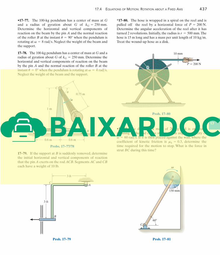
17.4 EQUATIONS OF MOTION: ROTATION ABOUT A FIXED AXIS 437 17 P = 200 N O r 10 mm Prob. 17–80 C B A 60° 150 mm Prob. 17–81 A B C 0.6 m 0.6 m 0.75 m 1 m G v v u Probs. 17–77/78 3 ft 3 ft A B C Prob. 17–79 *17–80. The hose is wrapped in a spiral on the reel and is pulled off the reel by a horizontal force of . Determine the angular acceleration of the reel after it has turned 2 revolutions. Initially, the radius is . The hose is 15 m long and has a mass per unit length of . Treat the wound-up hose as a disk. 10 kg> m r = 500 mm P = 200 N 17–79. If the support at B is suddenly removed, determine the initial horizontal and vertical components of reaction that the pin A exerts on the rod ACB. Segments AC and CB each have a weight of 10 lb. •17–77. The 100-kg pendulum has a center of mass at G and a radius of gyration about G of . Determine the horizontal and vertical components of reaction on the beam by the pin A and the normal reaction of the roller B at the instant when the pendulum is rotating at . Neglect the weight of the beam and the support. 17–78. The 100-kg pendulum has a center of mass at G and a radius of gyration about G of . Determine the horizontal and vertical components of reaction on the beam by the pin A and the normal reaction of the roller B at the instant when the pendulum is rotating at . Neglect the weight of the beam and the support. v = 4 rad> s u = 0° k G = 250 mm v = 8 rad> s u = 90° k G = 250 mm •17–81. The disk has a mass of 20 kg and is originally spinning at the end of the strut with an angular velocity of . If it is then placed against the wall, where the coefficient of kinetic friction is , determine the time required for the motion to stop. What is the force in strut BC during this time? m k = 0.3 v = 60 rad> s
-
Upload
khangminh22 -
Category
Documents
-
view
0 -
download
0
Transcript of 8-437-446 | Kinematics | Force - baixardoc
17.4 EQUATIONS OF MOTION: ROTATION ABOUT A FIXED AXIS 437
17
P � 200 N
O
r
10 mm
Prob. 17–80
C
�
BA
60�
150 mm
Prob. 17–81
A B
C
0.6 m 0.6 m
0.75 m
1 m
G
vv
u
Probs. 17–77/78
3 ft
3 ft
A
B
C
Prob. 17–79
*17–80. The hose is wrapped in a spiral on the reel and ispulled off the reel by a horizontal force of .Determine the angular acceleration of the reel after it hasturned 2 revolutions. Initially, the radius is .Thehose is 15 m long and has a mass per unit length of .Treat the wound-up hose as a disk.
10 kg>mr = 500 mm
P = 200 N
17–79. If the support at B is suddenly removed, determinethe initial horizontal and vertical components of reactionthat the pin A exerts on the rod ACB. Segments AC and CB
each have a weight of 10 lb.
•17–77. The 100-kg pendulum has a center of mass at Gand a radius of gyration about G of .Determine the horizontal and vertical components ofreaction on the beam by the pin A and the normal reactionof the roller B at the instant when the pendulum isrotating at . Neglect the weight of the beam andthe support.
17–78. The 100-kg pendulum has a center of mass at G and aradius of gyration about G of . Determine thehorizontal and vertical components of reaction on the beamby the pin A and the normal reaction of the roller B at theinstant when the pendulum is rotating at .Neglect the weight of the beam and the support.
v = 4 rad>su = 0°
kG = 250 mm
v = 8 rad>su = 90°
kG = 250 mm
•17–81. The disk has a mass of 20 kg and is originallyspinning at the end of the strut with an angular velocity of
. If it is then placed against the wall, where thecoefficient of kinetic friction is , determine thetime required for the motion to stop. What is the force instrut BC during this time?
mk = 0.3v = 60 rad>s
438 CH A P T E R 17 PL A N A R K I N E T I C S O F A R I G I D BO D Y: FO R C E A N D AC C E L E R AT I O N
17
B
C
F � 300 N
6 m
A
u � 60�
Prob. 17–82
O
3 ft
3 ft
20 lb
2 ft
F
Prob. 17–83
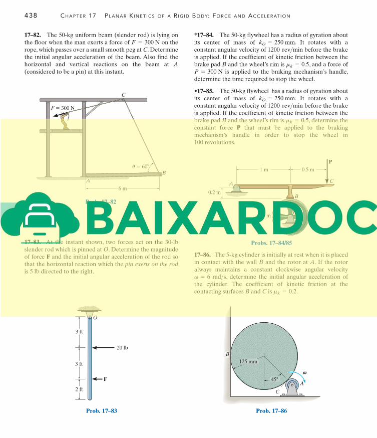
*17–84. The 50-kg flywheel has a radius of gyration aboutits center of mass of . It rotates with aconstant angular velocity of before the brakeis applied. If the coefficient of kinetic friction between thebrake pad B and the wheel’s rim is , and a force of
is applied to the braking mechanism’s handle,determine the time required to stop the wheel.
•17–85. The 50-kg flywheel has a radius of gyration aboutits center of mass of . It rotates with aconstant angular velocity of before the brakeis applied. If the coefficient of kinetic friction between thebrake pad B and the wheel’s rim is , determine theconstant force P that must be applied to the brakingmechanism’s handle in order to stop the wheel in100 revolutions.
mk = 0.5
1200 rev>minkO = 250 mm
P = 300 Nmk = 0.5
1200 rev>minkO = 250 mm
17–83. At the instant shown, two forces act on the 30-lbslender rod which is pinned at O. Determine the magnitudeof force F and the initial angular acceleration of the rod sothat the horizontal reaction which the pin exerts on the rod
is 5 lb directed to the right.
17–82. The 50-kg uniform beam (slender rod) is lying onthe floor when the man exerts a force of on therope, which passes over a small smooth peg at C. Determinethe initial angular acceleration of the beam. Also find thehorizontal and vertical reactions on the beam at A
(considered to be a pin) at this instant.
F = 300 N
17–86. The 5-kg cylinder is initially at rest when it is placedin contact with the wall B and the rotor at A. If the rotoralways maintains a constant clockwise angular velocity
, determine the initial angular acceleration ofthe cylinder. The coefficient of kinetic friction at thecontacting surfaces B and C is .mk = 0.2
v = 6 rad>s
C
A
vv
125 mm
45�
B
Prob. 17–86
P
1 m
0.2 m
0.5 m
0.3 mO
B
CA
Probs. 17–84/85
17.4 EQUATIONS OF MOTION: ROTATION ABOUT A FIXED AXIS 439
17
B
s
A
0.6 ft
Prob. 17–87
A
B
1 ft
2 ft
2 ft
1 ft
� 30 rad/s
C
E
D
v
Prob. 17–88
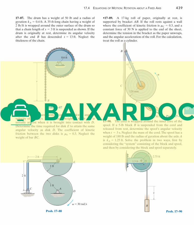
•17–89. A 17-kg roll of paper, originally at rest, issupported by bracket AB. If the roll rests against a wallwhere the coefficient of kinetic friction is , and aconstant force of 30 N is applied to the end of the sheet,determine the tension in the bracket as the paper unwraps,and the angular acceleration of the roll. For the calculation,treat the roll as a cylinder.
mC = 0.3
*17–88. Disk D turns with a constant clockwise angularvelocity of 30 . Disk E has a weight of 60 lb and isinitially at rest when it is brought into contact with D.Determine the time required for disk E to attain the sameangular velocity as disk D. The coefficient of kineticfriction between the two disks is . Neglect theweight of bar BC.
mk = 0.3
rad>s
17–87. The drum has a weight of 50 lb and a radius ofgyration . A 35-ft-long chain having a weight of2 is wrapped around the outer surface of the drum sothat a chain length of is suspended as shown. If thedrum is originally at rest, determine its angular velocityafter the end B has descended . Neglect thethickness of the chain.
s = 13 ft
s = 3 ftlb>ft
kA = 0.4 ft
17–90. The cord is wrapped around the inner core of thespool. If a 5-lb block B is suspended from the cord andreleased from rest, determine the spool’s angular velocitywhen . Neglect the mass of the cord. The spool has aweight of 180 lb and the radius of gyration about the axle Ais . Solve the problem in two ways, first byconsidering the “system” consisting of the block and spool,and then by considering the block and spool separately.
kA = 1.25 ft
t = 3 s
C
120 mm
B
aa
A
P � 30 N
60�
12
5
13
Prob. 17–89
B
s
2.75 ft
A1.5 ft
Prob. 17–90
(b)
�
G
IGA
m(aG)y
m(aG)x
maG
G
M1
M2
F4
F1
F2
F3
W
y
x
440 CH A P T E R 17 PL A N A R K I N E T I C S O F A R I G I D BO D Y: FO R C E A N D AC C E L E R AT I O N
17
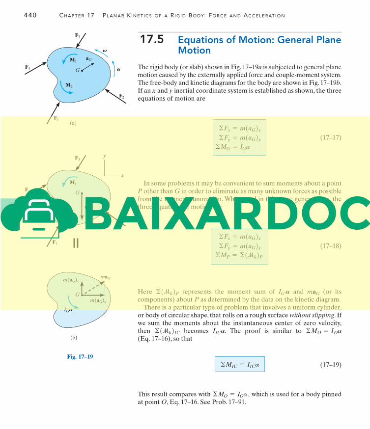
17.5 Equations of Motion: General PlaneMotion
The rigid body (or slab) shown in Fig. 17–19a is subjected to general planemotion caused by the externally applied force and couple-moment system.The free-body and kinetic diagrams for the body are shown in Fig. 17–19b.If an x and y inertial coordinate system is established as shown, the threeequations of motion are
(17–17)
In some problems it may be convenient to sum moments about a pointP other than G in order to eliminate as many unknown forces as possiblefrom the moment summation. When used in this more general case, thethree equations of motion are
(17–18)
Here represents the moment sum of and (or itscomponents) about P as determined by the data on the kinetic diagram.
There is a particular type of problem that involves a uniform cylinder,or body of circular shape, that rolls on a rough surface without slipping. Ifwe sum the moments about the instantaneous center of zero velocity,then becomes The proof is similar to (Eq. 17–16), so that
(17–19)
This result compares with which is used for a body pinnedat point O, Eq. 17–16. See Prob. 17–91.
©MO = IOa ,
©MIC = IICa
©MO = IOaIICa.©1mk2IC
maGIG A©1mk2P
©Fx = m1aG2x©Fy = m1aG2y
©MP = ©1mk2P
©Fx = m1aG2x©Fy = m1aG2y
©MG = IGa
aG
G
M1
M2
F4
F1
F2
F3
(a)
V
A
Fig. 17–19

17.5 EQUATIONS OF MOTION: GENERAL PLANE MOTION 441
17
Procedure for Analysis
Kinetic problems involving general plane motion of a rigid body canbe solved using the following procedure.
Free-Body Diagram.
• Establish the x, y inertial coordinate system and draw the free-body diagram for the body.
• Specify the direction and sense of the acceleration of the masscenter, and the angular acceleration of the body.
• Determine the moment of inertia
• Identify the unknowns in the problem.
• If it is decided that the rotational equation of motionis to be used, then consider drawing the kinetic
diagram in order to help “visualize” the “moments” developed bythe components and when writing the termsin the moment sum
Equations of Motion.
• Apply the three equations of motion in accordance with theestablished sign convention.
• When friction is present, there is the possibility for motion withno slipping or tipping. Each possibility for motion should beconsidered.
Kinematics.
• Use kinematics if a complete solution cannot be obtained strictlyfrom the equations of motion.
• If the body’s motion is constrained due to its supports, additionalequations may be obtained by using whichrelates the accelerations of any two points A and B on the body.
• When a wheel, disk, cylinder, or ball rolls without slipping, thenaG = ar.
aB = aA + aB>A ,
©1mk2P .
IG Am1aG2y ,m1aG2x ,
©MP = ©1mk2P
IG .
AaG ,
=
IG
Gy
Gx
FA
NA
maG
W
G
G
A
A
d
A
As the soil compactor, or “sheep’s footroller” moves forward, the roller hasgeneral plane motion. The forces shownon its free-body diagram cause the effectsshown on the kinetic diagram. If momentsare summed about the mass center, G,then However, if momentsare summed about point A (the ) thena+©MA = IGa + 1maG2d = IAa.
IC©MG = IGa.
442 CH A P T E R 17 PL A N A R K I N E T I C S O F A R I G I D BO D Y: FO R C E A N D AC C E L E R AT I O N
17
EXAMPLE 17.13
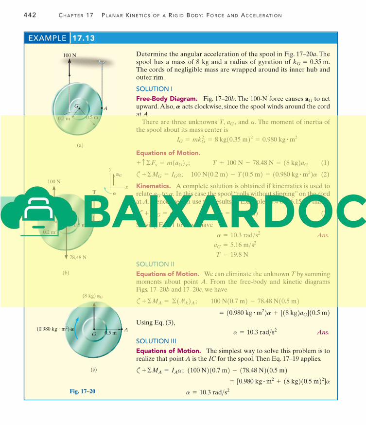
Determine the angular acceleration of the spool in Fig. 17–20a. Thespool has a mass of 8 kg and a radius of gyration of The cords of negligible mass are wrapped around its inner hub andouter rim.
SOLUTION I
Free-Body Diagram. Fig. 17–20b. The 100-N force causes to actupward. Also, acts clockwise, since the spool winds around the cordat A.
There are three unknowns T, and The moment of inertia ofthe spool about its mass center is
Equations of Motion.
(1)
c (2)
Kinematics. A complete solution is obtained if kinematics is used torelate to In this case the spool “rolls without slipping” on the cordat A. Hence, we can use the results of Example 16.4 or 16.15, so that
(c (3)
Solving Eqs. 1 to 3, we have
Ans.
SOLUTION II
Equations of Motion. We can eliminate the unknown T by summingmoments about point A. From the free-body and kinetic diagramsFigs. 17–20b and 17–20c, we have
c
Using Eq. (3),
Ans.
SOLUTION III
Equations of Motion. The simplest way to solve this problem is torealize that point A is the IC for the spool. Then Eq. 17–19 applies.
c
a = 10.3 rad>s2
= [0.980 kg # m2 + 18 kg210.5 m22]a1100 N210.7 m2 - 178.48 N210.5 m2+©MA = IAa ;
a = 10.3 rad>s2
= 10.980 kg # m22a + [18 kg2aG]10.5 m2100 N10.7 m2 - 78.48 N10.5 m2+©MA = ©1mk2A ;
T = 19.8 N
aG = 5.16 m>s2
a = 10.3 rad>s2
aG = a (0.5 m)+) aG = ar.
a.aG
100 N10.2 m2 - T10.5 m2 = 10.980 kg # m22a+©MG = IGa;
T + 100 N - 78.48 N = 18 kg2aG+ c©Fy = m1aG2y ;
IG = mkG2 = 8 kg10.35 m22 = 0.980 kg # m2
a.aG ,
A
aG
kG = 0.35 m.
0.5 m0.2 m
A
100 N
G
(a)
100 N
0.2 m
0.5 m
G
78.48 N
(b)
aG
y
xT
A
A
G
(8 kg) aG
(0.980 kg � m2)
(c)
AA0.5 m
Fig. 17–20
17.5 EQUATIONS OF MOTION: GENERAL PLANE MOTION 443
17
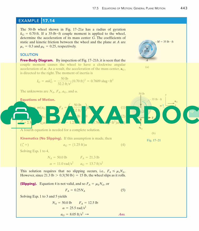
EXAMPLE 17.14
G
(a)
1.25 ft
M � 35 lb � ft
A
The 50-lb wheel shown in Fig. 17–21a has a radius of gyrationIf a couple moment is applied to the wheel,
determine the acceleration of its mass center G. The coefficients ofstatic and kinetic friction between the wheel and the plane at A are
and respectively.
SOLUTION
Free-Body Diagram. By inspection of Fig. 17–21b, it is seen that thecouple moment causes the wheel to have a clockwise angularacceleration of As a result, the acceleration of the mass center,is directed to the right. The moment of inertia is
The unknowns are and
Equations of Motion.
(1)
(2)
c (3)
A fourth equation is needed for a complete solution.
Kinematics (No Slipping). If this assumption is made, then
(c (4)
Solving Eqs. 1 to 4,
This solution requires that no slipping occurs, i.e.,However, since the wheel slips as it rolls.
(Slipping). Equation 4 is not valid, and so or
(5)
Solving Eqs. 1 to 3 and 5 yields
Ans.aG = 8.05 ft>s2:
a = 25.5 rad>s2
NA = 50.0 lb FA = 12.5 lb
FA = 0.25NA
FA = mkNA ,
21.3 lb 7 0.3150 lb2 = 15 lb,FA … msNA .
a = 11.0 rad>s2 aG = 13.7 ft>s2
NA = 50.0 lb FA = 21.3 lb
aG = 11.25 ft2a+)
35 lb # ft - 1.25 ft1FA2 = 10.7609 slug # ft22a+©MG = IGa;
NA - 50 lb = 0+ c©Fy = m1aG2y ;FA = a 50 lb
32.2 ft>s2baG:
+ ©Fx = m1aG2x ;
a.aG ,FA ,NA ,
IG = mkG2 =
50 lb
32.2 ft>s210.70 ft22 = 0.7609 slug # ft2
aG ,A.
mk = 0.25,ms = 0.3
35-lb # ftkG = 0.70 ft.
35 lb � ft
G
(b)
1.25 ft
50 lb
aG
y
x
FA
NA
A
Fig. 17–21
444 CH A P T E R 17 PL A N A R K I N E T I C S O F A R I G I D BO D Y: FO R C E A N D AC C E L E R AT I O N
17
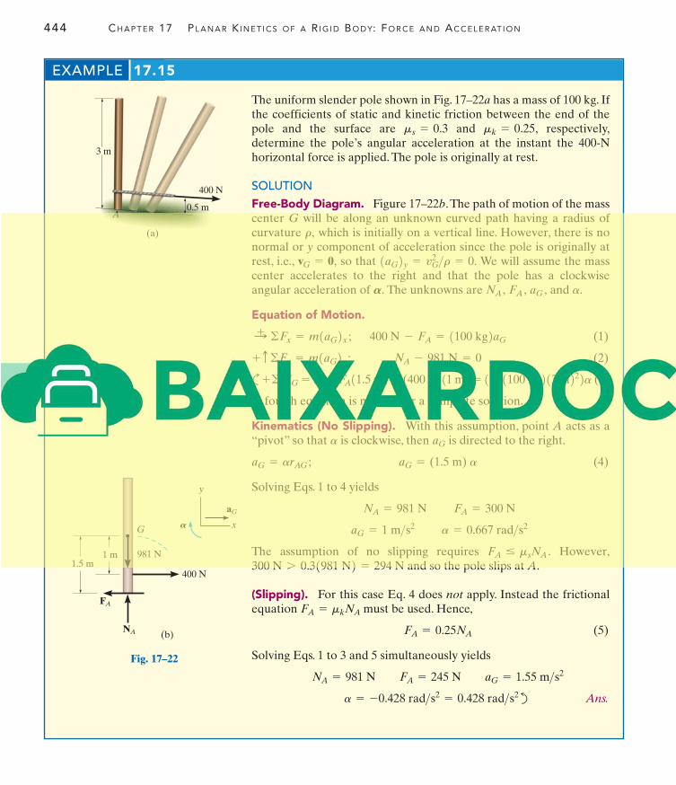
EXAMPLE 17.15
The uniform slender pole shown in Fig. 17–22a has a mass of 100 kg. Ifthe coefficients of static and kinetic friction between the end of thepole and the surface are and respectively,determine the pole’s angular acceleration at the instant the 400-Nhorizontal force is applied. The pole is originally at rest.
SOLUTION
Free-Body Diagram. Figure 17–22b.The path of motion of the masscenter G will be along an unknown curved path having a radius ofcurvature which is initially on a vertical line. However, there is nonormal or y component of acceleration since the pole is originally atrest, i.e., so that We will assume the masscenter accelerates to the right and that the pole has a clockwiseangular acceleration of The unknowns are and
Equation of Motion.
(1)
(2)
c (3)
A fourth equation is needed for a complete solution.
Kinematics (No Slipping). With this assumption, point A acts as a“pivot” so that is clockwise, then is directed to the right.
(4)
Solving Eqs. 1 to 4 yields
The assumption of no slipping requires However,and so the pole slips at A.
(Slipping). For this case Eq. 4 does not apply. Instead the frictionalequation must be used. Hence,
(5)
Solving Eqs. 1 to 3 and 5 simultaneously yields
d Ans.a = -0.428 rad>s2 = 0.428 rad>s2
NA = 981 N FA = 245 N aG = 1.55 m>s2
FA = 0.25NA
FA = mkNA
300 N 7 0.31981 N2 = 294 NFA … msNA .
aG = 1 m>s2 a = 0.667 rad>s2
NA = 981 N FA = 300 N
aG = (1.5 m) aaG = arAG ;
aGa
FA11.5 m2 - (400 N)11 m2 = 1[ 1121100 kg213 m222a+©MG = IGa;
NA - 981 N = 0+ c©Fy = m1aG2y ;400 N - FA = 1100 kg2aG:
+ ©Fx = m1aG2x ;
a.aG ,FA ,NA ,A.
1aG2y = vG2 >r = 0.vG = 0,
r,
mk = 0.25,ms = 0.3
0.5 m
400 N
3 m
(a)
A
1.5 m400 N
1 m
G
FA
NA
981 N
(b)
aG
y
xA
Fig. 17–22
17.5 EQUATIONS OF MOTION: GENERAL PLANE MOTION 445
17
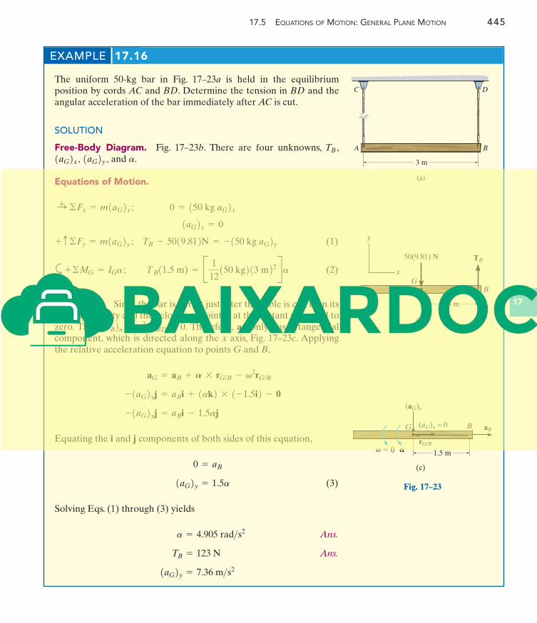
EXAMPLE 17.16
The uniform 50-kg bar in Fig. 17–23a is held in the equilibriumposition by cords AC and BD. Determine the tension in BD and theangular acceleration of the bar immediately after AC is cut.
SOLUTION
Free-Body Diagram. Fig. 17–23b. There are four unknowns,and .
Equations of Motion.
(1)
a (2)
Kinematics. Since the bar is at rest just after the cable is cut, then itsangular velocity and the velocity of point B at this instant are equal tozero. Thus . Therefore, only has a tangentialcomponent, which is directed along the x axis, Fig. 17–23c. Applyingthe relative acceleration equation to points G and B,
Equating the i and j components of both sides of this equation,
(3)
Solving Eqs. (1) through (3) yields
Ans.
Ans.
1aG2y = 7.36 m>s2
TB = 123 N
a = 4.905 rad>s2
1aG2y = 1.5a
0 = aB
-1aG2yj = aBi - 1.5aj
- 1aG2yj = aBi + 1ak2 * 1-1.5i2 - 0
aG = aB + A * rG/B - v2rG/B
aB1aB2n = vB2 >rBD = 0
TB11.5 m) = B 1
12150 kg213 m22Ra+©MG = IGa ;
TB - 5019.812N = -150 kg aG2y+ c©Fy = m1aG2y ;1aG2x = 0
0 = 150 kg aG2x:+ ©Fx = m1aG2x ;
a1aG2y ,1aG2x ,TB ,
C D
BA
3 m
(a)
B
1.5 m
50(9.81) N
(b)
x
y
TB
G
B
(c)
G
� 0
(aG)x = 0
(aG)y
aB
1.5 m
rG/B� �
Fig. 17–23
446 CH A P T E R 17 PL A N A R K I N E T I C S O F A R I G I D BO D Y: FO R C E A N D AC C E L E R AT I O N
17
FUNDAMENTAL PROBLEMS
F17–15
O
0.4 m
M � 100 N � m
F17–18
A
0.6 m
u
F17–16
0.15 m
30�
F17–17
0.4 m
0.6 m
BA
G M � 450 N � m
20 N
80 N
0.75 m 0.5 m1.75 m
0.3 m
P � 200 N
F17–14
F17–13
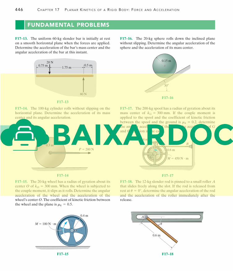
F17–16. The sphere rolls down the inclined planewithout slipping. Determine the angular acceleration of thesphere and the acceleration of its mass center.
20-kg
F17–15. The wheel has a radius of gyration about itscenter of When the wheel is subjected tothe couple moment, it slips as it rolls. Determine the angularacceleration of the wheel and the acceleration of thewheel’s center The coefficient of kinetic friction betweenthe wheel and the plane is mk = 0.5.
O.
kO = 300 mm.O20-kg
F17–13. The uniform slender bar is initially at reston a smooth horizontal plane when the forces are applied.Determine the acceleration of the bar’s mass center and theangular acceleration of the bar at this instant.
60-kg
F17–18. The slender rod is pinned to a small roller that slides freely along the slot. If the rod is released fromrest at determine the angular acceleration of the rodand the acceleration of the roller immediately after therelease.
u = 0°,
A12-kg
F17–14. The cylinder rolls without slipping on thehorizontal plane. Determine the acceleration of its masscenter and its angular acceleration.
100-kg F17–17. The spool has a radius of gyration about itsmass center of If the couple moment isapplied to the spool and the coefficient of kinetic frictionbetween the spool and the ground is determinethe angular acceleration of the spool, the acceleration of and the tension in the cable.
Gmk = 0.2,
kG = 300 mm.200-kg