The electromagnetic response of different metamaterial structures
9
The electromagnetic response of different metamaterial structures This content has been downloaded from IOPscience. Please scroll down to see the full text. Download details: IP Address: 61.219.241.170 This content was downloaded on 30/09/2013 at 14:16 Please note that terms and conditions apply. 2010 Adv. Nat. Sci: Nanosci. Nanotechnol. 1 045016 (http://iopscience.iop.org/2043-6262/1/4/045016) View the table of contents for this issue, or go to the journal homepage for more Home Search Collections Journals About Contact us My IOPscience
-
Upload
independent -
Category
Documents
-
view
5 -
download
0
Transcript of The electromagnetic response of different metamaterial structures

The electromagnetic response of different metamaterial structures
This content has been downloaded from IOPscience. Please scroll down to see the full text.
Download details:
IP Address: 61.219.241.170
This content was downloaded on 30/09/2013 at 14:16
Please note that terms and conditions apply.
2010 Adv. Nat. Sci: Nanosci. Nanotechnol. 1 045016
(http://iopscience.iop.org/2043-6262/1/4/045016)
View the table of contents for this issue, or go to the journal homepage for more
Home Search Collections Journals About Contact us My IOPscience

IOP PUBLISHING ADVANCES IN NATURAL SCIENCES: NANOSCIENCE AND NANOTECHNOLOGY
Adv. Nat. Sci.: Nanosci. Nanotechnol. 1 (2010) 045016 (8pp) doi:10.1088/2043-6262/1/4/045016
The electromagnetic response of differentmetamaterial structuresDinh Lam Vu1, Van Tuong Pham1, Thanh Viet Do2, Thanh Tung Nguyen2,Tran Thanh Thuy Vu3, Van Hong Le1 and Young Pak Lee3
1 Institute of Materials Science, Vietnam Academy of Science and Technology, Vietnam2 Institute of Engineering Physics, Vietnamese Military Academy of Science and Technology, Vietnam3 q-Psi and Department of Physics, Hanyang University, Seoul 133-791, Korea
E-mail: [email protected]
Received 2 November 2010Accepted for publication 25 December 2010Published 1 February 2011Online at stacks.iop.org/ANSN/1/045016
AbstractThis report investigates systematically the effect of structural parameters on the left-handedbehavior of a combined structure. The combined structure consists of a ‘cut-wire pair’,providing a negative magnetic permeability µ < 0, and a ‘continuous wire’, yielding anegative electric permittivity ε < 0. The left-handed metamaterials were designed, fabricatedand measured in the microwave-frequency regime. It was found that the width of thecontinuous wire as well as the distance between the substructures play an important role indetermining whether negative refractive properties (in other words, left-handed behavior) areobtained or not. Additionally, we studied the influence of the lattice constant on theelectromagnetic response of the combined structure. The actual measurements are comparedwith numerical simulation values to show good coincidence. Finally, we designed andsimulated an electromagnetic absorber made of metamaterials. It is expected that this workwill allow us to optimize appropriate characteristic parameters even without avoiding trial anderror fabrications.
Keywords: metamaterial, cut-wire pair, left-handed behavior, absorption
Classification number: 5.17
1. Introduction
In recent years, materials with simultaneously negativepermittivity and permeability (the so-called left-handedmaterials or LHMs) have become of special interest [1].LHMs are understood to be artificially engineered materialsthat exhibit a number of highly unusual and oftencounterintuitive physical properties. They have thereforebecome a field of intense research activity, not only becauseof basic research but also their promising applications.Although metamaterial research activities only started quiterecently, the results have already been covered in anumber of monographs. Using resonant electromagnetic (EM)structures, a variety of metamaterials have been demonstratedin every technologically relevant spectral range, from themicrowave [2] through the terahertz [3, 4] and near infraredregimes [5, 6], even up to visible frequencies [7, 8].
Many potential applications of metamaterials have beenproposed and studied both theoretically and experimentally,
such as superlenses [9], filters [10], antennas [11],electromagnetic cloaking [12, 13], biosensing [14] and,recently, perfect absorbers [15, 16]. In general, LHMsare artificial structures consisting of electric and magneticcomponents that have their own effective properties. Toapply the uniform effective-medium theory in determiningthe effective permittivity and permeability of these structures,the size of the unit cell should be much smaller thanthe wavelength. Hence, nanofabrication technologies arecrucial to obtain LHMs working at optical frequencies.Many interesting, but must-be-answered, questions on howto fabricate more isotropic LHMs and to push the operationfrequency to optical wavelengths remain to be furtherexplored. Therefore, the development of geometries andfabrication techniques for these materials is still an area ofsignificant effort. The design and construction of magneticand electric components play a central role in the EM responseof LHMs.
2043-6262/10/045016+08$30.00 1 © 2010 Vietnam Academy of Science & Technology

Adv. Nat. Sci.: Nanosci. Nanotechnol. 1 (2010) 045016 D L Vu et al
In this research, we have used the cut-wire pair insteadof the conventional split-ring resonator for constructingLHMs. The effect of the continuous wire width and thedistance between them on the electromagnetic response ofthe combined structure was demonstrated. The influenceof the lattice constant is also investigated. Finally, theelectromagnetic absorber made of metamaterials isdiscussed. The effect of the structural parameters on theabsorption properties of metamaterials is addressed. Themetamaterials were designed, fabricated and measured inthe microwave-frequency regime.
2. Experiment and simulation
Metamaterials were fabricated using the conventional printedcircuit board (PCB) process with copper patterns (0.036 mmthick) on both sides of a dielectric PCB (0.4 mm thick) witha dielectric constant of 4.0. The length and width of thecut-wire pair are 5.5 and 1.0 mm, respectively. In order toobtain the LH behavior, the cut-wire pair structures werecombined with the continuous wires. The unit cell of thecombined structure is shown with its geometric parametersin figure 1(a). The transmission spectra were measured infree space using a Hewlett-Packard E8362B network analyzerconnected to microwave standard-gain horn antennas.
A computer simulation technology microwave studio wasused for the numerical simulations. To obtain the effectiveparameters of the combined structure, we employed theretrieval procedure proposed by Chen et al [17]. For bothsimulation and experiment, the incident wave, k, is normalto the plane of the combined structure, while the electric field,E, is parallel to the continuous wire, as shown in figure 1.
3. Results and discussion
3.1. Negative refractive index of metamaterials
In this part, we present the results of the LH behavior, inother words, the negative refractive index of metamaterialsbased on the combined structure. The measured and calculatedtransmission spectra of the cut-wire pair and the combinedstructure are presented in figure 2, where the width of thecut-wire pair and continuous wire are kept at 1.0 mm. Ascan be seen, there exist two pass bands in the transmissionspectra of the combined structure that are separated by acertain amount of frequency. A good agreement betweenmeasurements and numerical simulations was achieved. Asexpected, the first transmission peak of the combined structureat approximately 13.8 GHz coincides with the band gapof the cut-wire pair. This indicates that this pass bandexhibits the LH behavior, but the other one at around17 GHz is the right-handed (RH) behavior [18, 19]. Theappearance of LH behavior can also be confirmed by using theextracted effective parameters of the combined structure, aspresented in figures 2(c) and (d). Obviously, both the effectivepermeability and permittivity are negative around the firstpeak; consequently, the refractive index has a negative value(n < 0), in other words, exhibiting the LH behavior. However,the remaining peak exhibits the RH behavior because bothpermeability and permittivity are positive.
(a)
(b)
Figure 1. (a) Geometry of the unit cell of the combined structure isviewed from the E–H, E–k and k–H plane. (b) Photograph of afabricated combined structure.
Besides the dependence of the structural parametersof the cut-wire pair on the LH behavior [19], we foundthat the electromagnetic response of the combined structureis considerably affected by the continuous wire. Figure 3presents the transmission spectra of the combined structureswith changing width of the continuous wire. For this study,the width of the cut-wire is kept at 1.0 mm while the width ofthe continuous wire is reduced from 1.0 to 0.5 mm.
As can be seen, the transmission peak exhibiting theLH behavior is significantly enhanced with the decrease inwidth of the continuous wire; however, the peak position isalmost unchanged (at 13.8 GHz). Together with this, it shouldbe noted that the RH transmission peak seems to be shiftedto a lower frequency as the width of the continuous wire isreduced. This makes the separation between these two peakssmaller. To verify this phenomenon, the effective permittivity,permeability and also refractive index of the combinedstructures are extracted from the scattering parameters, aspresented in figures 3(c) and (d). As expected, the plasmafrequency is moved to a lower frequency with decreasingwidth of the continuous wire, while the magnetic response isnearly unchanged. Therefore, this can explain why the RHpeak is shifted to a lower frequency according to reducing
2

Adv. Nat. Sci.: Nanosci. Nanotechnol. 1 (2010) 045016 D L Vu et al
12 13 14 15 16 17
-20
-10
0
12 13 14 15 16 17
-30
-20
-10
0
12 13 14 15 16 17-8
-4
0
4
12 13 14 15 16 17
-2
-1
0
1
Tra
nsm
issi
on (
dB)
Frequency (GHz)
Combined structure Cut-wire pair
(a)
Combined structure Cut-wire pair
Tra
nsm
issi
on (
dB)
Frequency (GHz)
(b)P
erm
ittiv
ity/P
erm
eabi
lity
Frequency (GHz)
Permittivity Permeability
(c) (d)
Ref
ract
ive
inde
x
Frequency (GHz)
Figure 2. (a) Measured and (b) simulated transmission spectra of the cut-wire pair and the combined structure, where the width of thecut-wire and continuous wire are 1.0 mm and the lattice constant in the H, E and k directions is 6.5, 7.0 and 1.4 mm, respectively. (c and d)Real part of the permittivity and refractive index extracted from the simulation data. The inset is the effective permeability.
the width of the continuous wire; consequently, the negativerefractive index is degraded, as shown in figure 3(d). Theenhancement of the LH behavior can be interpreted by theimpedance matching of the LH medium with the vacuumbackground [20], where the wave interaction of the cut-wirepairs and continuous wires plays an important role for lossesin the combined structure [21].
Another interesting result is shown in figure 4, wherethe LH behavior of the combined structure is also stronglyaffected by the distance d between the centers of thecontinuous wires. To study this phenomenon, the distanced was varied from 3.0 to 7.0 mm, and the lattice constantax = 2d, while ay = 7.5 mm and az = 1.4 mm. The effectivepermittivity, permeability and refractive index, obtained fromthe retrieval procedure, are shown to clarify this effect. As canbe seen, the magnetic resonance band is nearly unchanged, butthe plasma frequency is strongly shifted to a lower frequencywith increasing distance between the centers of the continuouswires. This leads to the LH transmission band (in other words,the negative refractive index band) being reduced accordingto d. In case d reaches 7 mm or larger, the LH behavior iscompletely destroyed.
In this work, we also investigated the LH behaviordependence on the lattice constant. To study the influence ofthe lattice constant ay in the E-direction, the lattice constantsalong the H- and k-directions are kept at ax = 6.5 mmand az = 1.4 mm, respectively, while in the E-direction thelattice constant is varied from 6.5 to 7.5 mm. The effective
parameters of these structures were retrieved from thecalculated scattering parameters as given in figure 5. It isobvious that the electric response of the combined structureis significantly affected by ay . As ay is reduced, the plasmafrequency of the combined structure is decreased. Even ay
is decreased to 6.5 mm, the plasma frequency is still higherthan the magnetic resonance frequency. This means that boththe permeability and the permittivity of this structure arenegative at the first peak (13.8 GHz). Therefore, the refractiveindex is still negative. If ay continues to be decreased, theplasma frequency is decreased accordingly to be lower thanthe magnetic frequency. At that time, the refractive indexbecomes positive; in other words, the LH behavior of thesecombined structures does not survive. This effect is due to thedecrease in the electric resonance frequency of the cut-wirepair when the distance between the cut-wire pairs along theE-direction; in other words, ay is decreased. Consequently,this leads to a decreased plasma frequency of the combinedstructure.
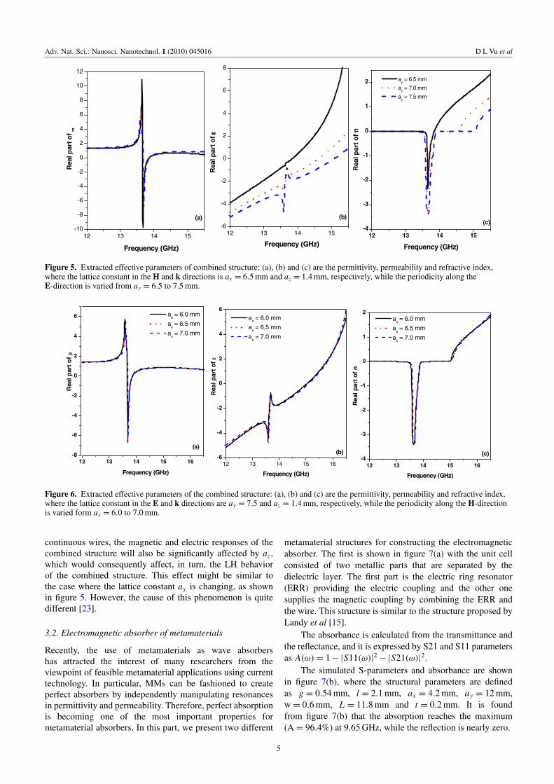
To study the influence of the lattice constant ax on theEM response of the combined structure, the periodicity axisis varied from 6.0 to 7.0 mm, but the distance between thecenters of continuous wires is kept at d = 3.0 mm. At thesame time, the periodicities in the (E, k) plane are ay =
7.5 mm and az = 1.4 mm, respectively. The extracted effectivepermittivity, permeability and refractive index are presented infigure 6. Interestingly, the negative refractive index is nearlyunaffected by the lattice constant ax in the H-direction. This
3

Adv. Nat. Sci.: Nanosci. Nanotechnol. 1 (2010) 045016 D L Vu et al
12 14 16-25
-20
-15
-10
-5
0
12 13 14 15 16 17-30
-20
-10
0
12 13 14 15 16-8
-4
0
4
12 13 14 15 16 17
-2
-1
0
1
Tra
nsm
issi
on (
dB)
Frequency (GHz)
wcontinuous wire
= 0.5 mm
wcontinuous wire
= 0.8 mm
wcontinuous wire
= 1.0 mm
(a) (b)
Tra
nsm
issi
on (
dB)
Frequency (GHz)
wcontinuous wire
= 0.5 mm
wcontinuous wire
= 0.8 mm
wcontinuous wire
= 1.0 mm
(c)
12 13 14 15 16 17
-1.0
-0.5
0.0
0.5
1.0
1.5
Per
mea
bilit
y
Frequency (GHz)
wcontinuous wire
= 0.5 mm
wcontinuous wire
= 0.8 mm
wcontinuous wire
= 1.0 mm
Per
mitt
ivity
Frequency (GHz)
wcontinuous wire
= 0.5 mm
wcontinuous wire
= 0.8 mm
wcontinuous wire
= 1.0 mm
(d)
Ref
ract
ive
inde
x
Frequency (GHz)
wcontinuous wire
= 0.5 mm
wcontinuous wire
= 0.8 mm
wcontinuous wire
= 1.0 mm
Figure 3. (a) Measured and (b) simulated transmission spectra of the combined structure with different widths of continuous wires.(c and d) The permittivity and refractive index. The effective permeability is shown in the inset.
12 13 14 15 16-1.0
-0.5
0.0
0.5
1.0
12 13 14 15 16-20
-10
0
10
20
12 13 14 15 16-3
-2
-1
0
1
d = 3.0 mm d = 4.0 mm d = 5.0 mm d = 7.0 mm
Per
mit
tivit
y
Frequency (GHz)
(a) (b)
d = 3.0 mm d = 4.0 mm d = 5.0 mm d = 7.0 mm
Per
mit
tivi
ty
Frequency (GHz)
(c)
Ref
ract
ive
ind
ex
Frequency (GHz)
d = 3.0 mm d = 4.0 mm d = 5.0 mm d = 7.0 mm
Figure 4. Extracted effective parameters of combined structure from the calculated scattering parameters: (a), (b) and (c) are thepermittivity, permeability and refractive index, where the lattice constant in the E and k directions is ay = 7.5 and az = 1.4 mm,respectively, while the distance between the centers of the continuous wires d is varied from 3.0 to 7.0 mm, and the periodicity along theH-direction is kept to be ax = 2d.
phenomenon is due to both the electric and the magneticresonances of the cut-wire pair being almost unaffected bythe lattice constant ax along the H-direction [22]. Therefore,when the cut-wire pairs are combined with the continuouswires, the plasma frequency of the combined structure willalso not be affected by the ax .
For the lattice constant in the k-direction, we have studiedin detail both theoretically and experimentally the effect of thelattice constants az on the EM response of the cut-wire pairmedium and found that az provides subtle effects not only onthe electric resonance but also on the magnetic resonance [22].Therefore, when the cut-wire pairs are combined with the
4
Adv. Nat. Sci.: Nanosci. Nanotechnol. 1 (2010) 045016 D L Vu et al
12 13 14 15-4
-3
-2
-1
0
1
2
12 13 14 15-6
-4
-2
0
2
4
6
8
12 13 14 15-10
-8
-6
-4
-2
0
2
4
6
8
10
12
(c)
Rea
l par
t o
f n
Frequency (GHz)
ay = 6.5 mm
ay = 7.0 mm
ay = 7.5 mm
(b)
Frequency (GHz)
Rea
l par
t o
f εε εε
Frequency (GHz)
Rea
l par
t o
f m
(a)
Figure 5. Extracted effective parameters of combined structure: (a), (b) and (c) are the permittivity, permeability and refractive index,where the lattice constant in the H and k directions is ax = 6.5 mm and az = 1.4 mm, respectively, while the periodicity along theE-direction is varied from ay = 6.5 to 7.5 mm.
12 13 14 15 16-8
-6
-4
-2
0
2
4
6
12 13 14 15 16-6
-4
-2
0
2
4
6
12 13 14 15 16-4
-3
-2
-1
0
1
2 ax = 6.0 mm
ax = 6.5 mm
ax = 7.0 mm
Frequency (GHz)
Rea
l par
t o
f µ
(a)
ax = 6.0 mm
ax = 6.5 mm
ax = 7.0 mm
Rea
l par
t o
f ε
Frequency (GHz)
(b)
Rea
l par
t o
f n
Frequency (GHz)
ax = 6.0 mm
ax = 6.5 mm
ax = 7.0 mm
(c)
Figure 6. Extracted effective parameters of the combined structure: (a), (b) and (c) are the permittivity, permeability and refractive index,where the lattice constant in the E and k directions are ay = 7.5 and az = 1.4 mm, respectively, while the periodicity along the H-directionis varied form ax = 6.0 to 7.0 mm.
continuous wires, the magnetic and electric responses of thecombined structure will also be significantly affected by az ,which would consequently affect, in turn, the LH behaviorof the combined structure. This effect might be similar tothe case where the lattice constant ay is changing, as shownin figure 5. However, the cause of this phenomenon is quitedifferent [23].
3.2. Electromagnetic absorber of metamaterials
Recently, the use of metamaterials as wave absorbershas attracted the interest of many researchers from theviewpoint of feasible metamaterial applications using currenttechnology. In particular, MMs can be fashioned to createperfect absorbers by independently manipulating resonancesin permittivity and permeability. Therefore, perfect absorptionis becoming one of the most important properties formetamaterial absorbers. In this part, we present two different
metamaterial structures for constructing the electromagneticabsorber. The first is shown in figure 7(a) with the unit cellconsisted of two metallic parts that are separated by thedielectric layer. The first part is the electric ring resonator(ERR) providing the electric coupling and the other onesupplies the magnetic coupling by combining the ERR andthe wire. This structure is similar to the structure proposed byLandy et al [15].
The absorbance is calculated from the transmittance andthe reflectance, and it is expressed by S21 and S11 parametersas A(ω) = 1 − |S11(ω)|2 − |S21(ω)|2.
The simulated S-parameters and absorbance are shownin figure 7(b), where the structural parameters are definedas g = 0.54 mm, l = 2.1 mm, ax = 4.2 mm, ay = 12 mm,w = 0.6 mm, L = 11.8 mm and t = 0.2 mm. It is foundfrom figure 7(b) that the absorption reaches the maximum(A = 96.4%) at 9.65 GHz, while the reflection is nearly zero.
5

Adv. Nat. Sci.: Nanosci. Nanotechnol. 1 (2010) 045016 D L Vu et al
(a) (b)
9.0 9.5 10.0 10.50.0
0.1
0.2
0.3
0.4
0.5
0.6
0.7
0.8
0.9
1.0
Ref
lect
ance
, Tra
nsm
itta
nce
, Ab
sorb
ance
Frequency(GHz)
Ref. Tran. Abs.
Figure 7. (a) Geometry of the unit cell of the metamaterial absorber. (b) The simulated S-parameters and absorptance where g = 0.54 mm,l = 2.1 mm, ax = 4.2 mm, ay = 12 mm, w = 0.6 mm, L = 11.8 mm and t = 0.2 mm.
0.0 0.1 0.2 0.3 0.4 0.5 0.6 0.7 0.80
10
20
30
40
50
60
70
80
90
100
Ab
sorb
ance
, Ref
lect
ance
, tra
nsm
itta
nce
Thickness of the dielectric layer t (mm)
Ref. Tran. Abs.
(a)0.0 0.2 0.4 0.6 0.8 1.0
0
10
20
30
40
50
60
70
80
90
100
Ref
lect
ance
, Tra
nsm
ittan
ce, A
bso
rban
ce(%
)
Width of the connected wire of ERR
Ref. Tran. Abs.
(b)
Figure 8. The reflectance, transmittance and absorptance depend on (a) the dielectric layer thickness t and (b) the width of connected wireof ERR.
Similar to the left-handed behavior, the electromagneticabsorption is also strongly affected by the structuralparameters. One example is presented in figure 8(a), wherethe dielectric layer thickness is changed and other parametersare kept constant. Clearly, the electromagnetic absorptionis increased with decreasing dielectric layer thickness fromt = 0.75 to 0.15 mm. When t is decreased until t = 0.15 mm,the absorbance peak curve reaches the maximum values.However, if t is continually decreased, the absorption isdecreased accordingly. The effect of the dielectric layerthickness can be explained due to changing the magneticcoupling of the structure according to the dielectric layerthickness [24].
Besides the dielectric layer thickness dependence, theabsorption is also remarkably dependent on the structuralparameters of the ERR. One of them is given in figure 8(b),where the width of the connected wire w of the ERR ischanged. It is found from figure 8(b) that at w = 0.45 mmthe absorption has a maximum value and the reflection
is at a minimum. This effect can be easily explained bychanging the electric coupling of the ERR based on theLC equivalent circuit. The above results suggest that byindependently manipulating resonances in permittivity andpermeability along with matching them, we can easily createa high absorber metamaterial with minimum reflection.
Finally, we introduced another design of metamaterialabsorber based on the cut-wire, as presented in figure 9(a).This structure comprises the single cut-wire metamaterialplaced on a perfect electric conductor surface, as illustrated infigure 9(a). Compared with the structure shown in figure 7, thecut-wire metamaterials have a simpler structure. The periodicunit cell is composed of only a dielectric substrate and a singlecut-wire. Due to this simplicity, cut-wire metamaterials areeasy to fabricate and can be transformed into other types ofmetamaterials.
Interestingly, the absorbance is significantly affected bythe thickness of the cut-wire, as presented in figures 9(a)–(c)where the thickness is varied from 2 to 50 nm. It is found
6

Adv. Nat. Sci.: Nanosci. Nanotechnol. 1 (2010) 045016 D L Vu et al
(a)
10 15 20 250.0
0.1
0.2
0.3
0.4
0.5
0.6
0.7
0.8
0.9
1.0
Ab
sorb
ance
Frequency(GHz)
t = 10nm t = 6nm t = 4nm t = 2nm
(c)
0 10 20 30 40 500.5
0.6
0.7
0.8
0.9
1.00 10 20 30 40 50
Ab
sorb
ance
pea
k
Thickness of the cut-wire nm(d)
10 15 20 250.0
0.1
0.2
0.3
0.4
0.5
0.6
0.7
0.8
0.9
1.0
Ab
sorb
ance
Frequency(GHz)
t = 50nm t = 40nm t = 30nm t = 20nm t = 10nm
(b)
Figure 9. (a) The unit cell of the metamaterial absorber based on the cut-wire, where the length and width of the cut-wire are 6 and 1 mm,respectively, while the dielectric layer thickness is kept as 0.4 mm; (b), (c) and (d) show the dependence of the absorbance on the thicknessof the cut-wire.
in figure 9 that the positions of the maximum absorbanceare fixed at around 13 GHz. In addition, it turns out thatthe absorbance peak curve reaches the maximum valueswith a cut-wire thickness of 10 nm. This absorbance peakdependence can also be explained by the LC equivalentcircuit [25]. In addition, we have studied the effect of thecut-wire length as well as the dielectric layer thickness onthe absorption. It was found that the position of the peakabsorption is strongly dependent on the cut-wire length. Thisresult suggests that we can design the broadband metamaterialabsorber by using the structure with the unit cell consisting ofdifferent lengths of cut-wires.
4. Conclusions
We have studied the effect of the structural parameters on theleft-handed behavior of a combined structure. It was foundthat the width of the continuous wire as well as the distancebetween the centers of the continuous wires strongly affect theleft-handed behavior of the combined structure. In the extreme
case, the left-handed behavior is completely eradicated. Wealso studied the influence of the lattice constant on theleft-handed behavior of the combined structure. The resultsshowed that the LH behavior is remarkably dependent on thelattice constant in the E- and k-directions. However, it remainsunchanged according to the lattice constant in the H-direction.Finally, the electromagnetic absorber made of metamaterialswas discussed. We presented two different metamaterialstructures for constructing the electromagnetic absorber. Ourresults showed that, similar to the left-handed behavior, theabsorption properties of metamaterials are also significantlyaffected by their structural parameters. The results suggestthat by independently manipulating resonances in permittivityand permeability along with matching them, we can easilycreate a high absorber metamaterial with minimum reflection.
Acknowledgments
This work was supported by the Key Laboratory forElectronic Materials and Devices—Institute of MaterialsScience, Vietnam Academy of Science and Technology.
7

Adv. Nat. Sci.: Nanosci. Nanotechnol. 1 (2010) 045016 D L Vu et al
References
[1] Veselago V G 1968 Sov. Phys.—Usp. 10 509[2] Smith D, Padilla W, Vier D, Nemat-Nesser S and Chultz S
2000 Phys. Rev. Lett. 84 4184[3] Yen T J, Padilla W J, Fang N, Vier D C, Smith D R, Pendry
J B, Basov D N and Zhang X 2004 Science 303 1494[4] Chen H T, O’Hara J F, Azad A, Taylor A J, Averitt R D,
Shrekenhamer D B and Padilla W J 2008 Nature Photonics2 295
[5] Zhang S, Fan W, Panoiu N C, Malloy K J, Osgood R M andBruech S R J 2005 Phys. Rev. Lett. 95 137404
[6] Enkrich C, Williard F P, Gerthsen D, Zhou J, Koschny T,Soukoulis C M, Wegener M and Linden S 2005Adv. Mater. 17 2547
[7] Dolling G, Wegener M, Soukoulis C M and Linden S 2006Opt. Lett. 32 53
[8] Liu N, Guo H, Fu L, Kaiser S, Schweizer H and Giessen H2008 Nat. Mat. 7 31
[9] Pendry J B 2000 Phys. Rev. Lett. 85 3966[10] Bonache J, Gil I, Garcia-Garcia J and Martin F 2006 IEEE
Trans. Microw. Theory Tech. 54 265[11] Engheta N 2002 IEEE Antennas Wireless Propag. Lett. 1 10[12] Pendry J B, Schurig D and Smith D R 2006 Science 312 1780
[13] Schurig D, Mock J J, Justice B J, Cummer S A, Pendry J B,Starr A F and Smith D R 2006 Science 314 977
[14] Lee H-J and Yook J-G 2008 Appl. Phys. Lett. 92 254103[15] Landy N I, Sajuyigbe S, Mock J J, Smith D R and Padilla W J
2008 Phys. Rev. Lett. 100 207402[16] Tao H, Landy N I, Bingham C M, Zhang X, Averitt D A and
Padilla W J 2008 Opt. Exp 16 7181[17] Chen X, Grzegorczyk M, Wu B-I, Pacheco J and Kong J A
2004 Phys. Rev. E 70 016608[18] Guven K, Caliskan M D and Ozbay E 2006 Opt. Express
14 8685[19] Lam V D, Kim J B, Lee S J and Lee Y P 2008 J. Appl. Phys.
103 033107[20] Simovski C R and Sauviac B 2004 Phys. Rev. E 70 046607[21] Tung N T, Lam V D, Park J W, Thuy V T and Lee Y P 2010
Eur. Phys. J. B 74 47[22] Lam V D, Tung N T, Cho M H, Park J W, Rhee J Y and Lee
Y P 2009 J. Appl. Phys. 105 113102[23] Lam V D, Kim J B, Lee S J, Lee Y P and Rhee J Y 2008
Opt. Express 16 5934[24] Lam V D, Tung N T, Cho M H, Jang W H and Lee Y P 2009
J. Phys. D: Appl. Phys. 42 115404[25] Wakatsuchi H, Greedy S, Christopoulos C and Paul J 2010
Opt. Express 18 22187
8