Revolution in Flexible Wearable Electronics for Temperature ...
Upload
khangminh22Category
view
0download
0
sensors
Article
A Flexible Metamaterial Based Printed Antenna for WearableBiomedical Applications
Ammar Al-Adhami * and Ergun Ercelebi
Citation: Al-Adhami, A.; Ercelebi, E.
A Flexible Metamaterial Based
Printed Antenna for Wearable
Biomedical Applications. Sensors
2021, 21, 7960. https://doi.org/
10.3390/s21237960
Academic Editors: Salam Khamas,
Zulkifly Abbas and Taha Elwi
Received: 11 October 2021
Accepted: 26 November 2021
Published: 29 November 2021
Publisher’s Note: MDPI stays neutral
with regard to jurisdictional claims in
published maps and institutional affil-
iations.
Copyright: © 2021 by the authors.
Licensee MDPI, Basel, Switzerland.
This article is an open access article
distributed under the terms and
conditions of the Creative Commons
Attribution (CC BY) license (https://
creativecommons.org/licenses/by/
4.0/).
Department of Electrical Electronics Engineering, Gaziantep University, Gaziantep 27310, Turkey;[email protected]* Correspondence: [email protected]
Abstract: This paper presents a microstrip antenna based on metamaterials (MTM). The proposedantenna showed several resonances around the BAN and ISM frequency bands. The antenna showeda suitable gain for short and medium wireless communication systems of about 1 dBi, 1.24 dBi,1.48 dBi, 2.05 dBi, and 4.11 dBi at 403 MHz, 433 MH, 611 Mz, 912 MHz, and 2.45 GHz, respectively.The antenna was printed using silver nanoparticle ink on a polymer substrate. The antenna sizewas reduced to 20 × 10 mm2 to suit the different miniaturized wireless biomedical devices. Thefabricated prototype was tested experimentally on the human body. The main novelty with thisdesign is its ability to suppress the surface wave from the patch edges, significantly reducing theback radiation toward the human body when used close to it. The antenna was located on the humanhead to specify the specific absorption rate (SAR). It was found in all cases that the proposed antennashowed low SAR effects on the human body.
Keywords: SAR; flexible antenna; wearable; MTM
1. Introduction
In the last decade, electronic systems miniaturization has led to an increased demandfor wearable devices that can monitor the human body’s functions [1]; thus, wearable healthmanagement systems became a most attractive field for researchers. This is due to the factthat such wearable devices can function well enough to replace several medical instrumentswhen embedded in smart clothes [2]. In order apply such technology, researchers developeda variety of miniaturized antennas with adequate performance [3]. However, to employwearable systems in biomedical applications, several practical specifications in antennadesign must be considered, such as small size, low weight, power consumption, andflexible structure [4]. For this, a number of microstrip antennas were introduced as one ofthe most desired categories for wearable applications when mounted close to the humanbody [5].
Subsequently, significant demands for wearable antennas to be compact and to nothave unnecessary setup requirements were increased for self-adaptive wireless systems [6].It is worth mentioning that one of the main research interests of wearable antennas iswireless body area network applications [7]. Consequently, printed circuit antennas becameattractive due to their unique properties, such as their being very compatible with therequirements of wearable systems [8]. The main important advantages of using printedantennas for wearable systems are their cost-effectiveness, design simplicity, and theirrelative biocompatibility [9]. Moreover, one of the important advantages of using printedcircuit antennas with wearable systems is that they can be mounted on flexible and/or semi-flexible substrates, maintaining their performance against physical bending and twistingeffects [10]. Thus, attention must be paid during the design process to consider employingsuitable materials for the wearable antenna fabrication [11]. Such considerations have adirect effect on a fabricated antenna’s efficiency and bandwidth, where they are usuallyhighly affected by substrate thickness and the dielectric constant [12].
Sensors 2021, 21, 7960. https://doi.org/10.3390/s21237960 https://www.mdpi.com/journal/sensors

Sensors 2021, 21, 7960 2 of 18
Currently, significant interest has been raised with regard to flexible and semi-flexiblesubstrates for telemedicine and biomedical applications [13]. Much attention was paid tothe use of flexible and semi-flexible materials for wearable nodes production [13]. With thegreat advancements in wearable antenna technologies, a significant development has beenobserved in their utilization for implantable devices [14]. However, operating antennasat low frequency ranges with miniaturized size for wearable devices without affectingradiation efficiency and gain is one of the more relevant challenges in the current stateof the art [15]. To resolve such a problem, various efforts have been made to reducethe size of wearable antennas using reactive loads [16], utilizing materials with highpermittivity [17], and using vias [18], shorting posts [19], and fractal geometries to increasethe current path [20]. When the mentioned techniques have been applied, the antennasize has been significantly reduced. However, different difficulties appeared, such asbandwidth reduction, design complexity, and gain degradations [8]. In addition, eventhough wearable antennas were applied in different technologies based on smart clothes,they still suffered from different issues, such as their influences on the hosting body,the effect of their location on different body parts on their operation, and the possibleoccurrence of significant efficiency and reliability losses due to antenna deformation [18].Therefore, a critical issue in wearable antenna design that must be considered is minimizingelectromagnetic leakages toward the human body.
In another aspect, biocompatible materials such as polyamide substrates have recentlyattracted researchers to include them in their designs for wearable antennas [15]. This isdue to their excellent mechanical properties, including but not limited to their light weight,flexibility, tensile strength, durability, high-heat resistance (up to 400 C), excellent electricalproperties, high moisture release characteristics, and low moisture uptake [17]. On theother hand, due to the properties of human tissue that have high permittivity, when thehuman body is exposed to the electromagnetic waves that radiate from a wearable antenna,the body absorbs a large amount of this energy [19]. As is well known, the parameters of awearable antenna are decreased noticeably during its functioning near the human body,which causes significant problems in the wireless communication field [5]. Furthermore,electromagnetic waves absorbed by the human body have undesirable environmentaland biological impact [6]. Several types of wearable antennas have been developed inthe past. The authors of [7] designed a compact triangular patch antenna; however, theantenna has a very narrow operating bandwidth. A low-sized cpw-fed slot antenna withfloating ground plane for ISM band was designed in [7]; however, the designed antennahad a very low fractional bandwidth (6% at the center frequency of 5.825 GHz). Severalother wearable antennas such as electromagnetic bandgap (EBG)-based antennas [2] andsubstrate-integrated waveguide (SIW)-based antennas [10] have been designed; however,all of these antennas have had a narrow bandwidth.
In this paper, a low profile and flexible printed wearable antenna was designed forISM bands including 403 MHz, 433 MH, 611 Mz, 912 MHz, and 2.45 GHz for remotehealth-monitoring applications. The antenna was based on a polyimide substrate, which isknown for its flexibility and robustness. The performance of the proposed antenna wasacceptable in terms of gain, operating bandwidth, and efficiency in the bending scenarios.In addition, the antenna has appropriate gain, acceptable bandwidth, and high efficiencyin on-body worn scenarios. Moreover, the antenna has a reasonably low SAR value whenmounted on the human body.
2. Antenna Geometry
The antenna is constructed from an MTM patch of a complementary Minkowski fractalgeometry to realize multiple frequency resonance within a miniaturized size. The patch isfed with 50 Ω coplanar waveguide (CPW) to achieve excellent matching at several bands [6].Two matching circuits are introduced (see Figure 1a) between the patch structure and theCPW ground plane to reduce the reflection effects [10]. Nevertheless, the advantage ofadding those matching circuits is to suppress the surface waves along the patch edges [12].

Sensors 2021, 21, 7960 3 of 18
Sensors 2021, 21, x FOR PEER REVIEW 3 of 21
[6]. Two matching circuits are introduced (see Figure 1a) between the patch structure and
the CPW ground plane to reduce the reflection effects [10]. Nevertheless, the advantage
of adding those matching circuits is to suppress the surface waves along the patch edges
[12].
Figure 1. The antenna geometrical: (a) front view, (b) side view, and (c) back view.
In the same context, reducing the effects of the surface waves reflections from the
substrate edges is achieved by etching MTM defects from the proposed CPW ground
plane [18], which minimizes the back radiation. In turn, the electromagnetic leakage to-
ward the human body would be reduced significantly [10]. As seen in Figure 1b, the an-
tenna dimensions are 20 mm × 20 mm when printed on a polymer substrate of 0.3 mm
thickness with relative permittivity of 3.5 and loss tangent of 0.0001. The antenna back
panel is covered with a partial ground plane to reduce the effects of the capacitive cou-
pling with the patch structure [13].
Finally, the antenna structure is printed using conductive ink based on silver nano-
particles of conductivity of around 1.3 × 10⁶ s/m. The novelty of the proposed design is
that by considering the complementary Minkowski geometry, such a structure can there-
fore dominate the magnetic field instead of the electrical field [10]. Consequently, SAR
effects would be insignificant on human tissue where the human body permeability is
unity [13].
3. MTM Characterizations
The proposed MTM is defined as sub-wavelength composites of right–left hand
structures with negative εr and μr at the frequency bands of interest. The resonance fre-
quency of the proposed MTM unit cell is affected by substrate height and permittivity
[12]. Therefore, CSTMWS based on the finite integral technique (FIT) [21] was invoked to
investigate the proposed MTM behavior in terms of S-parameters and dispersion dia-
gram. As seen in Figure 2, the proposed unit cell is etched from a transmission line ground
plane to obtain quasi-TEM-like modes [9]. In that simulation, the upper and lower ±y axes
faces are considered perfect electrical conductors (PEC). The other two faces along the ±x
axes are subjected as perfect magnetic conductors (PMC). The waveguide ports are as-
signed ±z axes. It is important to mention that the proposed unit cell is normal to the ex-
citation ports. This was taken into consideration because the proposed unit cell is etched
from the patch surface in which the electric field would be normal to the patch surface [7].
Figure 1. The antenna geometrical: (a) front view, (b) side view, and (c) back view.
In the same context, reducing the effects of the surface waves reflections from thesubstrate edges is achieved by etching MTM defects from the proposed CPW groundplane [18], which minimizes the back radiation. In turn, the electromagnetic leakagetoward the human body would be reduced significantly [10]. As seen in Figure 1b, theantenna dimensions are 20 mm × 20 mm when printed on a polymer substrate of 0.3 mmthickness with relative permittivity of 3.5 and loss tangent of 0.0001. The antenna backpanel is covered with a partial ground plane to reduce the effects of the capacitive couplingwith the patch structure [13].
Finally, the antenna structure is printed using conductive ink based on silver nanopar-ticles of conductivity of around 1.3 × 10⁶ s/m. The novelty of the proposed design is thatby considering the complementary Minkowski geometry, such a structure can thereforedominate the magnetic field instead of the electrical field [10]. Consequently, SAR effectswould be insignificant on human tissue where the human body permeability is unity [13].
3. MTM Characterizations
The proposed MTM is defined as sub-wavelength composites of right–left hand struc-tures with negative εr and µr at the frequency bands of interest. The resonance frequency ofthe proposed MTM unit cell is affected by substrate height and permittivity [12]. Therefore,CSTMWS based on the finite integral technique (FIT) [21] was invoked to investigate theproposed MTM behavior in terms of S-parameters and dispersion diagram. As seen inFigure 2, the proposed unit cell is etched from a transmission line ground plane to obtainquasi-TEM-like modes [9]. In that simulation, the upper and lower ±y axes faces areconsidered perfect electrical conductors (PEC). The other two faces along the ±x axes aresubjected as perfect magnetic conductors (PMC). The waveguide ports are assigned ±zaxes. It is important to mention that the proposed unit cell is normal to the excitation ports.This was taken into consideration because the proposed unit cell is etched from the patchsurface in which the electric field would be normal to the patch surface [7].
Here, the proposed unit cell structure is characterized in terms of S-parameters, S11and S12, and dispersion diagram. As seen in Figure 3a, the proposed unit cell showsmore than single frequency resonance within the bandwidth of interest. The authorstreated this unit cell as explained in [9]. Therefore, based on the resulting variation in thewave velocity for such unit cell at the first Brillion zone, see the dispersion diagram inFigure 3a, the wave propagation band gap can be evaluated. From the observed results atthe first transverse electrical and magnetic modes, the proposed unit cell shows a band gap

Sensors 2021, 21, 7960 4 of 18
between the frequency range of 1 GHz and 2.43 GHz; which make it a good candidate forsuch applications [12].
Sensors 2021, 21, x FOR PEER REVIEW 4 of 21
Figure 2. EBG unit cell: (a) CSTMWS numerical setup and (b) unit cell dimensions in mm scale.
Here, the proposed unit cell structure is characterized in terms of S-parameters, S11
and S12, and dispersion diagram. As seen in Figure 3a, the proposed unit cell shows more
than single frequency resonance within the bandwidth of interest. The authors treated this
unit cell as explained in [9]. Therefore, based on the resulting variation in the wave veloc-
ity for such unit cell at the first Brillion zone, see the dispersion diagram in Figure 3a, the
wave propagation band gap can be evaluated. From the observed results at the first trans-
verse electrical and magnetic modes, the proposed unit cell shows a band gap between
the frequency range of 1 GHz and 2.43 GHz; which make it a good candidate for such
applications [12].
Figure 2. EBG unit cell: (a) CSTMWS numerical setup and (b) unit cell dimensions in mm scale.
Based on the simulation results, the proposed unit cell equivalent circuit model isderived as seen in Figure 4. The equivalent capacitances of coupling between the unit celland adjacent cells are indicated as Left Hand (LH) capacitor of (CLH), and the fractal slot isconsidered as an inductor (LLH) where the magnetic current motion in the air traces canbe magnified [12]. This inductor is equivalent to the magnetic field that is stored insidethe rings’ fractal slots [6]. The other presented elements are considered for the traditionalmedium of propagation due to the Right Hand (RH) transmission part, which is given byLRH, RRH, GRH, and CRH as inductance, resistance, conductance, and capacitance elements.These parameters are driven by coupling effects between the T-resonator the fractal shapein the unit cell [12].
The lumped elements of the proposed circuit in Figure 3 were evaluated based ona parametric study inside Advanced Design System (ADS) environments, and they arelisted in Table 1. Therefore, the frequency resonance can be tuned by varying the gapwidth between the T-resonator in the unit cell and the fractal geometry. Consequently,a parametric study was applied by changing the gap between the T-resonator, and thefractal geometry (G) was conducted to determine the operating resonance frequency, whichled to the desired unit cell properties at the frequency band of interest. Figure 5 displaysthe conducted parametric study on the parameter G from 0.1 mm to 0.7 mm, with a stepof 0.1 mm. The achieved results in terms of S11 and S12 spectra were monitored. It wasobserved that |S21| spectra were significantly affected by g1 value variation. Therefore,the resonant frequency shifted from 0.38 GHz at g1 = 0.3 mm to 0.68 GHz at g1 = 0.7 mm.

Sensors 2021, 21, 7960 5 of 18
It was observed from the obtained results at g1 = 0.5 mm that the matching impedance wassignificantly enhanced at 0.4 GHz.
Sensors 2021, 21, x FOR PEER REVIEW 5 of 21
Figure 3. Unit cell characterizations: (a) S-parameters and (b) dispersion diagram.
Based on the simulation results, the proposed unit cell equivalent circuit model is
derived as seen in Figure 4. The equivalent capacitances of coupling between the unit cell
and adjacent cells are indicated as Left Hand (LH) capacitor of (CLH), and the fractal slot
is considered as an inductor (LLH) where the magnetic current motion in the air traces can
be magnified [12]. This inductor is equivalent to the magnetic field that is stored inside
the rings’ fractal slots [6]. The other presented elements are considered for the traditional
medium of propagation due to the Right Hand (RH) transmission part, which is given by
LRH, RRH, GRH, and CRH as inductance, resistance, conductance, and capacitance elements.
These parameters are driven by coupling effects between the T-resonator the fractal shape
in the unit cell [12].
Figure 3. Unit cell characterizations: (a) S-parameters and (b) dispersion diagram.
Sensors 2021, 21, x FOR PEER REVIEW 6 of 21
Figure 4. Equivalent circuit of the proposed unit cell.
The lumped elements of the proposed circuit in Figure 3 were evaluated based on a
parametric study inside Advanced Design System (ADS) environments, and they are
listed in Table 1. Therefore, the frequency resonance can be tuned by varying the gap
width between the T-resonator in the unit cell and the fractal geometry. Consequently, a
parametric study was applied by changing the gap between the T-resonator, and the frac-
tal geometry (G) was conducted to determine the operating resonance frequency, which
led to the desired unit cell properties at the frequency band of interest. Figure 5 displays
the conducted parametric study on the parameter G from 0.1 mm to 0.7 mm, with a step
of 0.1 mm. The achieved results in terms of S11 and S12 spectra were monitored. It was
observed that |S21| spectra were significantly affected by g1 value variation. Therefore,
the resonant frequency shifted from 0.38 GHz at g1 = 0.3 mm to 0.68 GHz at g1 = 0.7 mm.
It was observed from the obtained results at g1 = 0.5 mm that the matching impedance
was significantly enhanced at 0.4 GHz.
Figure 4. Equivalent circuit of the proposed unit cell.

Sensors 2021, 21, 7960 6 of 18
Table 1. Lumped element values of the equivalent circuit model in Figure 4.
Element Value
RLH 12.2 ΩRRH 50 ΩGLH 0.1 SGRH 4 SCLH 1.1 pFCRH 3.1 pFLLH 3 nHLRH 2.2 nH
Sensors 2021, 21, x FOR PEER REVIEW 7 of 21
Figure 5. Varying effects of G dimension on the S-parameter spectra: (a) S11 and (b) S12.
Table 1. Lumped element values of the equivalent circuit model in Figure 4.
Element Value
RLH 12.2 Ω
RRH 50 Ω
GLH 0.1 S
GRH 4 S
CLH 1.1 pF
CRH 3.1 pF
LLH 3 nH
LRH 2.2 nH
4. Design Methodology
In this section, a parametric study based on numerical simulations was conducted
inside CSTMWS environments based on the finite integral technique algorithm [21]. For
this study, the antenna geometrical parameters were changed parametrically to realize the
optimal antenna performance in terms of bandwidth and gain. Therefore, the antenna S11
spectra, gain spectra, and radiation patterns were monitored by varying the antenna di-
mensions. The proposed antenna dimensions were swept to maintain the frequency bands
around 403 MHz, 433 MH, 611 Mz, 912 MHz, and 2.45 GHz. For this, the parametric study
was conducted by changing the antenna design parameters as follows:
4.1. Patch Design
A parametric study was applied to the proposed patch by changing the geometry
from solid patch to defected MTM patch based on Minkowski fractal. As seen in Figure
Figure 5. Varying effects of G dimension on the S-parameter spectra: (a) S11 and (b) S12.
4. Design Methodology
In this section, a parametric study based on numerical simulations was conductedinside CSTMWS environments based on the finite integral technique algorithm [21]. Forthis study, the antenna geometrical parameters were changed parametrically to realize theoptimal antenna performance in terms of bandwidth and gain. Therefore, the antennaS11 spectra, gain spectra, and radiation patterns were monitored by varying the antennadimensions. The proposed antenna dimensions were swept to maintain the frequencybands around 403 MHz, 433 MH, 611 Mz, 912 MHz, and 2.45 GHz. For this, the parametricstudy was conducted by changing the antenna design parameters as follows:
4.1. Patch Design
A parametric study was applied to the proposed patch by changing the geometryfrom solid patch to defected MTM patch based on Minkowski fractal. As seen in Figure 6a,the S11 spectra of the proposed patch showed more frequency modes than the identical

Sensors 2021, 21, 7960 7 of 18
ones based on the solid patch. This is due to the fact of the effects of the fractal geometry onthe generated modes because of the multi path current motion [3]. Moreover, the proposedantenna gain was enhanced significantly in comparison with the sold patch, as seen inFigure 6b. For example, the antenna gain at 403 MHz was found at about 1 dBi, and at2.45 GHz it was enhanced to 4.1 dBi. Such enhancements are attributed to surface wavesuppression [9].
Sensors 2021, 21, x FOR PEER REVIEW 8 of 21
6a, the S11 spectra of the proposed patch showed more frequency modes than the identical
ones based on the solid patch. This is due to the fact of the effects of the fractal geometry
on the generated modes because of the multi path current motion [3]. Moreover, the pro-
posed antenna gain was enhanced significantly in comparison with the sold patch, as seen
in Figure 6b. For example, the antenna gain at 403 MHz was found at about 1 dBi, and at
2.45 GHz it was enhanced to 4.1 dBi. Such enhancements are attributed to surface wave
suppression [9].
Figure 6. Effects of changing the patch configuration shape: (a) S11 spectra and (b) gain spectra.
4.2. Matching Circuit
The authors investigated the effect of changing the matching circuit length on the
antenna performance in terms of the S11 spectrum only. Therefore, three lengths were ex-
amined, starting from 4 mm to 12 mm in a step of 4 mm. Figure 7 shows the impact of
changing the matching load length (L) on the evaluated S11 spectra. The obtained results
show that changing the mating length directly affected the antenna bandwidth due to the
fact of tuning the real part of antenna impedance with respect to the characteristic imped-
ance of the source [7]. Nevertheless, with increasing L, a significant reduction in the field
fringing from substrate edge [9] consequently enhanced the antenna bandwidth. There-
fore, the authors decided to fix the matching circuit length to 12 mm.
Figure 6. Effects of changing the patch configuration shape: (a) S11 spectra and (b) gain spectra.
4.2. Matching Circuit
The authors investigated the effect of changing the matching circuit length on theantenna performance in terms of the S11 spectrum only. Therefore, three lengths wereexamined, starting from 4 mm to 12 mm in a step of 4 mm. Figure 7 shows the impact ofchanging the matching load length (L) on the evaluated S11 spectra. The obtained resultsshow that changing the mating length directly affected the antenna bandwidth due tothe fact of tuning the real part of antenna impedance with respect to the characteristicimpedance of the source [7]. Nevertheless, with increasing L, a significant reduction inthe field fringing from substrate edge [9] consequently enhanced the antenna bandwidth.Therefore, the authors decided to fix the matching circuit length to 12 mm.

Sensors 2021, 21, 7960 8 of 18Sensors 2021, 21, x FOR PEER REVIEW 9 of 21
Figure 7. Effects of changing the matching impedance length on S11 spectra.
4.3. MTM Effects
In this section, the authors decided to conduct a parametric study on the effects of
the MTM row number, see Figure 1a, on the proposed antenna performance in terms of
S11 and gain spectra. The results of this study are shown in Figure 8; the results again
reveal excellent enhancements in the antenna bandwidth by increasing the MTM array
from 1 row to 3 rows with a step of 1 row. This is attributed to the fact that suppressing
the surface wave was increased by increasing the number of MTM rows [9].
Figure 7. Effects of changing the matching impedance length on S11 spectra.
4.3. MTM Effects
In this section, the authors decided to conduct a parametric study on the effects of theMTM row number, see Figure 1a, on the proposed antenna performance in terms of S11and gain spectra. The results of this study are shown in Figure 8; the results again revealexcellent enhancements in the antenna bandwidth by increasing the MTM array from 1 rowto 3 rows with a step of 1 row. This is attributed to the fact that suppressing the surfacewave was increased by increasing the number of MTM rows [9].
Sensors 2021, 21, x FOR PEER REVIEW 10 of 21
Figure 8. Antenna performance by varying the MTM rows: (a) S11 and (b) gain spectra. Figure 8. Antenna performance by varying the MTM rows: (a) S11 and (b) gain spectra.
5. Bending Effects and Radiation Leakages
In this section, the variation in the antenna S11 spectra was monitored after bendingthe antenna close to the human head. Additionally, SAR effects are discussed with respect

Sensors 2021, 21, 7960 9 of 18
to human tissue. This study was conducted by invoking the voxel model of Sam phantomstructure inside CSTMWS environments as follows:
5.1. Bending Effect
The antenna was subjected to the bending effects on a cylindrical geometry withdifferent angles from 0 to 45 with a step of 15. It was observed that when the antennawas subjected to the bending effects it showed insignificant changes in terms of S11 spectra,as seen in Figure 9; this was due to the current motion on the fractal patch structure notbeing significantly affected because of the MTM structure at the feed point [8].
Sensors 2021, 21, x FOR PEER REVIEW 11 of 21
5. Bending Effects and Radiation Leakages
In this section, the variation in the antenna S11 spectra was monitored after bending
the antenna close to the human head. Additionally, SAR effects are discussed with respect
to human tissue. This study was conducted by invoking the voxel model of Sam phantom
structure inside CSTMWS environments as follows:
5.1. Bending Effect
The antenna was subjected to the bending effects on a cylindrical geometry with dif-
ferent angles from 0° to 45° with a step of 15°. It was observed that when the antenna was
subjected to the bending effects it showed insignificant changes in terms of S11 spectra, as
seen in Figure 9; this was due to the current motion on the fractal patch structure not being
significantly affected because of the MTM structure at the feed point [8].
Figure 9. Antenna S11 spectra with varying the bending angle.
5.2. Radiation Leakage
Since the proposed study was subjected to the applications of wearable applications,
a SAR study based on radiation leakage from the antenna toward the human tissue was
studied. The effects of the absorbed radiation in the human head are studied numerically
in this section. In the simulation, the input power level was considered to be 1 mW. We
focused on the proposed antenna design to realize minimum leakage toward human tis-
sue by adding two fractal unit cells near the feeding port. In Figure 10a, the values of the
radiation leakage in terms of electric field (E-Field) strength are presented. In this study,
the antenna was mounted close to the human head with varying distances from 0 mm to
50 mm, with a step of 5 mm. It is important to mention that the bending effect was applied,
here at 45°, without considering the flat case in the comparison. The quantity of absorption
was given by evaluating the SAR results on the SAM model of the human body inside
CSTMWS environments, as in Figure 10b. It is important to mention that the SAM model
was simulated inside CSTMWS environments with a resolution of 1 mm3 [13]. As seen in
Figure 10b, the SAR quantity was found to be 0.25 W/kg and 0.33 W/kg at 403 MHz and
2.45 GHz, respectively, with a distance of 5 mm. Finally, the field strength leakages from
the antenna toward the human head were about 101 mV/m and 133 mV/m at 403 MHz
and 2.45 GHz, respectively.
Figure 9. Antenna S11 spectra with varying the bending angle.
5.2. Radiation Leakage
Since the proposed study was subjected to the applications of wearable applications,a SAR study based on radiation leakage from the antenna toward the human tissue wasstudied. The effects of the absorbed radiation in the human head are studied numericallyin this section. In the simulation, the input power level was considered to be 1 mW. Wefocused on the proposed antenna design to realize minimum leakage toward human tissueby adding two fractal unit cells near the feeding port. In Figure 10a, the values of theradiation leakage in terms of electric field (E-Field) strength are presented. In this study,the antenna was mounted close to the human head with varying distances from 0 mm to50 mm, with a step of 5 mm. It is important to mention that the bending effect was applied,here at 45, without considering the flat case in the comparison. The quantity of absorptionwas given by evaluating the SAR results on the SAM model of the human body insideCSTMWS environments, as in Figure 10b. It is important to mention that the SAM modelwas simulated inside CSTMWS environments with a resolution of 1 mm3 [13]. As seen inFigure 10b, the SAR quantity was found to be 0.25 W/kg and 0.33 W/kg at 403 MHz and2.45 GHz, respectively, with a distance of 5 mm. Finally, the field strength leakages fromthe antenna toward the human head were about 101 mV/m and 133 mV/m at 403 MHzand 2.45 GHz, respectively.

Sensors 2021, 21, 7960 10 of 18Sensors 2021, 21, x FOR PEER REVIEW 12 of 21
Figure 10. Antenna radiation leakage in terms of: (a) E-field and (b) SAR.
6. Experimental Results and Discussions
After arriving at the optimal antenna design, the authors decided to fabricate the an-
tenna design as presented in Figure 11. The proposed antenna was fabricated using a con-
ductive ink of silver nanoparticle printed with a Fujifilm Dimatix materials printer. The
fabricated antenna was tested experimentally including: S11 spectrum, radiation patterns,
and field radiation leakages.
Figure 10. Antenna radiation leakage in terms of: (a) E-field and (b) SAR.
6. Experimental Results and Discussions
After arriving at the optimal antenna design, the authors decided to fabricate theantenna design as presented in Figure 11. The proposed antenna was fabricated using aconductive ink of silver nanoparticle printed with a Fujifilm Dimatix materials printer. Thefabricated antenna was tested experimentally including: S11 spectrum, radiation patterns,and field radiation leakages.
During the measurement process, the authors invoked the use of an RF chock with50 coaxial cables connected to a professional network analyzer of the Agilent family ofPNA 8720. The antenna measurements were performed inside an RF anechoic chamber asfollows:

Sensors 2021, 21, 7960 11 of 18Sensors 2021, 21, x FOR PEER REVIEW 13 of 21
Figure 11. Fabricated antenna prototype: (a) front view, (b) back view, (c) SAM model inside
CSTMWS, (d) SAM model during the experimental measurements, (e) antenna gain measurement,
and (f) radiation pattern measurement.
Figure 11. Fabricated antenna prototype: (a) front view, (b) back view, (c) SAM model insideCSTMWS, (d) SAM model during the experimental measurements, (e) antenna gain measurement,and (f) radiation pattern measurement.

Sensors 2021, 21, 7960 12 of 18
6.1. Antenna Characterizations
The proposed antenna was fabricated and tested. In this matter, S11 spectra andradiation patterns of the proposed antenna at different frequency bands with differentbending scenarios in the free space were measured. Later, the same measurements wereperformed again when the antenna was mounted close to the human head. The proposedantenna was measured within the frequency band from 0.1 GHz up to 3 GHz. As seen inFigure 12, the antenna S11 spectra were measured for bended profile, at 15 and flat case, inwhich it was mounted off and on the human head. In Figure 12, the antenna S11 spectrumis presented in the free space based on the flat case; it was found that the proposed antennashowed a frequency resonance at 403 MHz, 433 MH, 611 Mz, 912 MHz, and 2.45 GHz, withan S11 value below −10 dB. Subsequently, when the antenna was subjected to bending at15, the antenna S11 and the frequency resonance values were not significantly affected, asseen in Figure 12b, which agrees with the results in the previous section. After that, theantenna based on the flat profile was mounted close to the human head to assess whetherthere were human tissue effects from the antenna S11 spectra, as depicted in Figure 12c.We found that frequency resonance was shifted slightly at high frequency bands, around2.45 GHz; however, lower frequency bands showed insignificant changes. This was likelydue to the fact that wave scattering from the antenna edges at low frequencies wereinsignificant [10]. Next, when the antenna was subjected to bending effects and placed onthe human head, the antenna S11 spectrum, generally, was not changed significantly, aspresented in Figure 12d.
Sensors 2021, 21, x FOR PEER REVIEW 14 of 21
During the measurement process, the authors invoked the use of an RF chock with
50 coaxial cables connected to a professional network analyzer of the Agilent family of
PNA 8720. The antenna measurements were performed inside an RF anechoic chamber as
follows:
6.1. Antenna Characterizations
The proposed antenna was fabricated and tested. In this matter, S11 spectra and radi-
ation patterns of the proposed antenna at different frequency bands with different bend-
ing scenarios in the free space were measured. Later, the same measurements were per-
formed again when the antenna was mounted close to the human head. The proposed
antenna was measured within the frequency band from 0.1 GHz up to 3 GHz. As seen in
Figure 12, the antenna S11 spectra were measured for bended profile, at 15° and flat case,
in which it was mounted off and on the human head. In Figure 12, the antenna S11 spec-
trum is presented in the free space based on the flat case; it was found that the proposed
antenna showed a frequency resonance at 403 MHz, 433 MH, 611 Mz, 912 MHz, and 2.45
GHz, with an S11 value below −10 dB. Subsequently, when the antenna was subjected to
bending at 15°, the antenna S11 and the frequency resonance values were not significantly
affected, as seen in Figure 12b, which agrees with the results in the previous section. After
that, the antenna based on the flat profile was mounted close to the human head to assess
whether there were human tissue effects from the antenna S11 spectra, as depicted in Fig-
ure 12c. We found that frequency resonance was shifted slightly at high frequency bands,
around 2.45 GHz; however, lower frequency bands showed insignificant changes. This
was likely due to the fact that wave scattering from the antenna edges at low frequencies
were insignificant [10]. Next, when the antenna was subjected to bending effects and
placed on the human head, the antenna S11 spectrum, generally, was not changed signifi-
cantly, as presented in Figure 12d.
Figure 12. Antenna S11 spectra for two proposed profiles: (a) flat in free space, (b) flat on the human
head, (c) bended in free space, and (d) bended on the human head.
Next, the antenna gain spectra were measured for the proposed antenna within the
frequency band of interest as well as in the same scenarios. It was found that the proposed
antenna realized insignificant variation in the antenna gain in comparison with the effects
of bending or being mounted on the human body, as seen in Figure 13.
Figure 12. Antenna S11 spectra for two proposed profiles: (a) flat in free space, (b) flat on the humanhead, (c) bended in free space, and (d) bended on the human head.
Next, the antenna gain spectra were measured for the proposed antenna within thefrequency band of interest as well as in the same scenarios. It was found that the proposedantenna realized insignificant variation in the antenna gain in comparison with the effectsof bending or being mounted on the human body, as seen in Figure 13.
Subsequently, the antenna radiation patterns at 403 MHz, 433 MH, 611 Mz, 912 MHz,and 2.45 GHz were measured for the flat and bended profiles in the free space as seenin Figure 14. It was found that the proposed antenna showed an absolute gain of 1 dBi,1.24 dBi, 1.48 dBi, 2.05 dBi, and 4.11 dBi at 403 MHz, 433 MH, 611 Mz, 912 MHz, and2.45 GHz, respectively. Such gain values were found to be very stable for short and mediumwireless communication systems. Additionally, the antenna performances were not foundto be significantly affected with bending, making it an excellent candidate for wearableapplication. It is important to mention that during the measurement the input power wasconsidered to be 1 mW. In this section, a comparison between different antennas that wereintroduced in the literature for modern applications from different aspects are compared to

Sensors 2021, 21, 7960 13 of 18
the proposed antenna designs. It is clear from Table 2, that the proposed antenna, to thebest of the authors’ knowledge, provides excellent gain with mutable frequency bands witha limited area in comparison with data on those antennas that were published previously.
Sensors 2021, 21, x FOR PEER REVIEW 15 of 21
Figure 13. Antenna gain spectra for two proposed profiles: (a) flat in free space, (b) flat on the human
head, (c) bended in free space, and (d) bended on the human head.
Subsequently, the antenna radiation patterns at 403 MHz, 433 MH, 611 Mz, 912 MHz,
and 2.45 GHz were measured for the flat and bended profiles in the free space as seen in
Figure 14. It was found that the proposed antenna showed an absolute gain of 1 dBi, 1.24
dBi, 1.48 dBi, 2.05 dBi, and 4.11 dBi at 403 MHz, 433 MH, 611 Mz, 912 MHz, and 2.45 GHz,
respectively. Such gain values were found to be very stable for short and medium wireless
communication systems. Additionally, the antenna performances were not found to be
significantly affected with bending, making it an excellent candidate for wearable appli-
cation. It is important to mention that during the measurement the input power was con-
sidered to be 1 mW. In this section, a comparison between different antennas that were
introduced in the literature for modern applications from different aspects are compared
to the proposed antenna designs. It is clear from Table 2, that the proposed antenna, to the
best of the authors’ knowledge, provides excellent gain with mutable frequency bands
with a limited area in comparison with data on those antennas that were published pre-
viously.
Table 2. A comparison of the proposed antenna performance with respect to the published designs.
Ref. Gain Size Center Frequency Substrate Type
[1] −20 dBi λ/5 5 GHz Fabric
[2] 3 dBi λ/5 1.5 GHz Solar panel polymer
[3] 4 0.12λ 2.45 GHz Roger TMM10i
[4] 4.4 0.29λ 5.8 GHz Unknown
[5] 2.33 3.27 mm 10.1, 24.6 GHz Rogers RO3010
[6] 3.7 0.06 λ 2.45 GHz Meta-cell
[7] 5.1 0.13 λ 2 GHz Rogers RO4003C
[8] 7.1 16 mm 2.4, 5.8 GHz Rogers 3210
The proposed
work
1 dBi, 1.24 dBi, 1.48 dBi,
2.05 dBi, and 4.11 dBi 20 × 10 mm2
403 MHz, 433 MH, 611 Mz, 912
MHz, and 2.45 GHz Polymer
Figure 13. Antenna gain spectra for two proposed profiles: (a) flat in free space, (b) flat on the humanhead, (c) bended in free space, and (d) bended on the human head.
Table 2. A comparison of the proposed antenna performance with respect to the published designs.
Refs. Gain Size Center Frequency Substrate Type
[1] −20 dBi λ/5 5 GHz Fabric
[2] 3 dBi λ/5 1.5 GHz Solar panel polymer
[3] 4 0.12λ 2.45 GHz Roger TMM10i
[4] 4.4 0.29λ 5.8 GHz Unknown
[5] 2.33 3.27 mm 10.1, 24.6 GHz Rogers RO3010
[6] 3.7 0.06 λ 2.45 GHz Meta-cell
[7] 5.1 0.13 λ 2 GHz Rogers RO4003C
[8] 7.1 16 mm 2.4, 5.8 GHz Rogers 3210
The proposed work 1 dBi, 1.24 dBi, 1.48 dBi,2.05 dBi, and 4.11 dBi 20 × 10 mm2
403 MHz, 433 MH,611 Mz, 912 MHz, and
2.45 GHzPolymer
As a next step, the authors applied the same study when the antenna was mountedclose to the human head. It was found that most of the radiation patterns were directedaway from the human head due to the effects of the MTM at the feed position, as discussedlater. The antenna radiation patterns for both flat and bended profiles close to the humanhead were insignificantly affected. It is important to mention that the proposed antennawas located at a 5 mm distance from human tissue. In general, the simulated and measuredresults were in good agreement for all cases, as depicted in Figure 15. The antenna showedgood immunity against bending without significant effects of the human head on antennaperformance.

Sensors 2021, 21, 7960 14 of 18Sensors 2021, 21, x FOR PEER REVIEW 16 of 21
Figure 14. Antenna radiation patterns in free space: (a) 403 MHz, (b) 433 MH, (c) 611 Mz, (d) 912
MHz, and (e) 2.45 GHz.
As a next step, the authors applied the same study when the antenna was mounted
close to the human head. It was found that most of the radiation patterns were directed
away from the human head due to the effects of the MTM at the feed position, as discussed
later. The antenna radiation patterns for both flat and bended profiles close to the human
head were insignificantly affected. It is important to mention that the proposed antenna
Figure 14. Antenna radiation patterns in free space: (a) 403 MHz, (b) 433 MH, (c) 611 Mz, (d)912 MHz, and (e) 2.45 GHz.

Sensors 2021, 21, 7960 15 of 18
Sensors 2021, 21, x FOR PEER REVIEW 17 of 21
was located at a 5 mm distance from human tissue. In general, the simulated and meas-
ured results were in good agreement for all cases, as depicted in Figure 15. The antenna
showed good immunity against bending without significant effects of the human head on
antenna performance.
Figure 15. Antenna radiation patterns when close to the human body: (a) 403 MHz, (b) 433 MH, (c)
611 Mz, (d) 912 MHz, and (e) 2.45 GHz.
Figure 15. Antenna radiation patterns when close to the human body: (a) 403 MHz, (b) 433 MH, (c)611 Mz, (d) 912 MHz, and (e) 2.45 GHz.
In Figure 16, the proposed antenna performance was measured in terms of S11 and gainspectra in the free space and when mounted on the human head. During the measurements,the antenna was bended from 0 to 45, with a step of 15. It was found that the proposedantenna performance was not changed significantly at low frequency bands, showingexcellent stability against bending effects. Such stability was achieved due to the surfacewave suppression at the patch and substrate edges [20]. Nevertheless, bending effects

Sensors 2021, 21, 7960 16 of 18
usually result in a significant change on the frequency resonance of wearable antennas; thisis usually attributed to the effects of the equivalent antenna capacitive variation that wouldincrease with the increase in antenna bending effects [2]. However, in our case, the antennapatch was constructed from a fractal antenna structure that was shaped from a meanderline within a limited area; such a configuration generates a magnetic field componentnormal to patch edges that reduces the capacitive effects [17] and maintains the surfacecurrent distribution on the patch when it is subjected to bending [18].
Sensors 2021, 21, x FOR PEER REVIEW 18 of 21
In Figure 16, the proposed antenna performance was measured in terms of S11 and
gain spectra in the free space and when mounted on the human head. During the meas-
urements, the antenna was bended from 0° to 45°, with a step of 15°. It was found that the
proposed antenna performance was not changed significantly at low frequency bands,
showing excellent stability against bending effects. Such stability was achieved due to the
surface wave suppression at the patch and substrate edges [20]. Nevertheless, bending
effects usually result in a significant change on the frequency resonance of wearable an-
tennas; this is usually attributed to the effects of the equivalent antenna capacitive varia-
tion that would increase with the increase in antenna bending effects [2]. However, in our
case, the antenna patch was constructed from a fractal antenna structure that was shaped
from a meander line within a limited area; such a configuration generates a magnetic field
component normal to patch edges that reduces the capacitive effects [17] and maintains
the surface current distribution on the patch when it is subjected to bending [18].
Figure 16. Antenna S11 and gain spectra measurements in free space and the wearable scenarios: (a)
flat in free space, (b) flat on the human head, (c) bended in free space, and (d) bended on the human
head.
6.2. Radiation Leakage
The radiation leakage from the proposed antenna toward the human tissue was
measured in terms electrical field strength using a field probe meter. As seen in Figure 17,
the proposed antenna showed a field strength leakage toward the human head of about
101 mV/m at 403 MHz and 133 mV/m at 2.45 GHz for the flat profile. The radiation leakage
was measured at different distances between the proposed antenna on bended profile and
the human head of about 5 mm up to 25 mm, with a step of 5 mm, as seen in Figure 17. It
was found that the radiation leakage was reduced significantly after 25 mm from the pro-
posed antenna for both flat and bended profiles. These measurements were conducted
using a TM-195 RF 3-axie field strength meter.
Figure 16. Antenna S11 and gain spectra measurements in free space and the wearable scenarios: (a)flat in free space, (b) flat on the human head, (c) bended in free space, and (d) bended on the humanhead.
6.2. Radiation Leakage
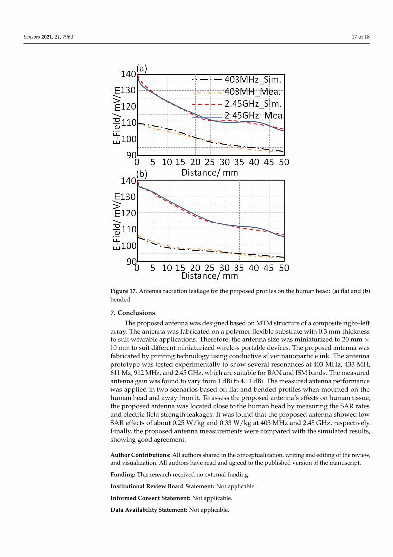
The radiation leakage from the proposed antenna toward the human tissue wasmeasured in terms electrical field strength using a field probe meter. As seen in Figure 17,the proposed antenna showed a field strength leakage toward the human head of about101 mV/m at 403 MHz and 133 mV/m at 2.45 GHz for the flat profile. The radiationleakage was measured at different distances between the proposed antenna on bendedprofile and the human head of about 5 mm up to 25 mm, with a step of 5 mm, as seen inFigure 17. It was found that the radiation leakage was reduced significantly after 25 mmfrom the proposed antenna for both flat and bended profiles. These measurements wereconducted using a TM-195 RF 3-axie field strength meter.
In Table 3 is presented a comparison between the proposed antenna performance andother published results in the literature in terms of SAR amount at different frequencybands. It was found that the proposed antenna showed less SAR amount than otherconsidered references.
Table 3. A comparison of SAR values.
References Human Part SAR (W/kg) Centre Frequency (MHz) Centre Frequency (MHz)
[5] Head tissue 0.52~0.76 900–1800 900–1800
[6] Head tissue 0.92 2400~25002500~2690 2400~2500
[7] Head tissue —[8] Head tissue 0.45 900 —[9] Head tissue 0.45 850~2200 900[10] Wrist tissue 0.32~0.48 1960~1980 850~2200[11] — 0.28~0.43 930~1900 1960~1980
Proposed antenna Head tissue 0.32~0.54 403~2450 930~1900
Sensors 2021, 21, 7960 17 of 18Sensors 2021, 21, x FOR PEER REVIEW 19 of 21
Figure 17. Antenna radiation leakage for the proposed profiles on the human head: (a) flat and (b)
bended.
In Table 3 is presented a comparison between the proposed antenna performance
and other published results in the literature in terms of SAR amount at different frequency
bands. It was found that the proposed antenna showed less SAR amount than other con-
sidered references.
Table 3. A comparison of SAR values.
Reference Human Part SAR (W/kg) Centre Frequency (MHz) Centre Frequency (MHz)
[5] Head tissue 0.52~0.76 900–1800 900–1800
[6] Head tissue 0.92 2400~2500
2500~2690 2400~2500
[7] Head tissue ---
[8] Head tissue 0.45 900 ---
[9] Head tissue 0.45 850~2200 900
[10] Wrist tissue 0.32~0.48 1960~1980 850~2200
[11] --- 0.28~0.43 930~1900 1960~1980
Proposed an-
tenna Head tissue 0.32~0.54 403, 2450 930~1900
7. Conclusions
The proposed antenna was designed based on MTM structure of a composite right–
left array. The antenna was fabricated on a polymer flexible substrate with 0.3 mm thick-
ness to suit wearable applications. Therefore, the antenna size was miniaturized to 20 mm
Figure 17. Antenna radiation leakage for the proposed profiles on the human head: (a) flat and (b)bended.
7. Conclusions
The proposed antenna was designed based on MTM structure of a composite right–leftarray. The antenna was fabricated on a polymer flexible substrate with 0.3 mm thicknessto suit wearable applications. Therefore, the antenna size was miniaturized to 20 mm ×10 mm to suit different miniaturized wireless portable devices. The proposed antenna wasfabricated by printing technology using conductive silver nanoparticle ink. The antennaprototype was tested experimentally to show several resonances at 403 MHz, 433 MH,611 Mz, 912 MHz, and 2.45 GHz, which are suitable for BAN and ISM bands. The measuredantenna gain was found to vary from 1 dBi to 4.11 dBi. The measured antenna performancewas applied in two scenarios based on flat and bended profiles when mounted on thehuman head and away from it. To assess the proposed antenna’s effects on human tissue,the proposed antenna was located close to the human head by measuring the SAR ratesand electric field strength leakages. It was found that the proposed antenna showed lowSAR effects of about 0.25 W/kg and 0.33 W/kg at 403 MHz and 2.45 GHz, respectively.Finally, the proposed antenna measurements were compared with the simulated results,showing good agreement.
Author Contributions: All authors shared in the conceptualization, writing and editing of the review,and visualization. All authors have read and agreed to the published version of the manuscript.
Funding: This research received no external funding.
Institutional Review Board Statement: Not applicable.
Informed Consent Statement: Not applicable.
Data Availability Statement: Not applicable.

Sensors 2021, 21, 7960 18 of 18
Conflicts of Interest: The authors declare no conflict of interest.
References1. Abdulsattar, R.K.; Elwi, T.A.; Hassain, Z.A.A. A New Microwave Sensor Based on the Moore Fractal Structure to Detect Water
Content in Crude Oil. Sensors 2021, 21, 7143. [CrossRef] [PubMed]2. Alaukally, M.N.N.; Elwi, T.A.; Atilla, D.C. Miniaturized flexible metamaterial antenna of circularly polarized high gain-bandwidth
product for radio frequency energy harvesting. Int. J. Commun. Syst. 2021, e5024. [CrossRef]3. Ali, D.; Elwi, T.; Özbay, S. Metamaterial-based Printed Circuit Antenna for Biomedical Applications. Avrupa Bilim Ve Teknol. Derg.
2021, 26, 12–15. [CrossRef]4. Lmako, J. Specific Absorption Rate (SAR) Testing, from a Test Laboratory Perspective; No. 211 7901; Radio Frquency Investigation Ltd.:
Basingstoke, UK, 2000.5. Kumaran, N.; Arunachalam, K. A Wideband non-Resonant FSS with Finite Number of Unit Cells for Mobile Phone SAR Reduction.
In Proceedings of the International Conference on Electromagnetics in Advanced Applications (ICEAA), Cairns, QLD, Australia,19–23 September 2016; pp. 901–904.
6. Bhattacharjee, S.; Mitra, M.; Chaudhuri, S.R.B. Improved Matching and SAR Reduction with Little Angular Instable AMC BasedGround Plane. In Proceedings of the International Microwave and RF Conference, New Delhi, India, 5–9 December 2016; pp. 1–4.
7. Hariharan, V.; Maheshwaran, S.; Selvam, S.; Gunavathi, N. Comparison of Electromagnetic Band Gap (EBG) Structures for SpecificAbsorption Rate (SAR) Reduction. In Proceedings of the India Conference (INDICON), New Delhi, India, 17–20 December 2015;pp. 1–4.
8. Han, K.; Swaminathan, M.; Pulugurtha, R.; Sharma, H.; Tummala, R.; Yang, S.; Nair, V. Magneto-dielectric Nanocomposite forAntenna Miniaturization and SAR Reduction. IEEE Antennas Wirel. Propag. Lett. 2015, 5, 72–75. [CrossRef]
9. Haridim, M. Use of Rod Reflectors for SAR Reduction in Human Head. IEEE Trans. Electromagn. Compat. 2015, 58, 40–46.[CrossRef]
10. Il Kwak, S.; Sim, D.U.; Kwon, J.H.; Yoon, Y.J. Design of PIFA with Metamaterials for Body-SAR Reduction in Wearable Applications.IEEE Trans. Electromagn. Compat. 2016, 59, 279–300.
11. Abdel-Mageed, M.; Pelleti, C.; Mittra, R. Penta-Band PIFA for SAR Reduction for Mobile and WLAN Applications Using R-Card.In Proceedings of the IEEE International Symposium on Antennas and Propagation USNC/URSI National Radio Science Meeting,Vancouver, BC, Canada, 19–24 July 2015; pp. 374–375.
12. Elwi, T.A. Electromagnetic Band Gap Structures based an Ultra Wideband Microstrip Antenna. Microw. Opt. Technol. Lett. 2017,59, 827–834. [CrossRef]
13. Elwi, T.A.; Imran, A.I.; Alnaiemy, Y. A Miniaturized Lotus Shaped Microstrip Antenna Loaded with EBG Structures for HighGain-Bandwidth Product Applications. Prog. Electromagn. Res. C 2015, 60, 157–167. [CrossRef]
14. Elwi, T.A. A Miniaturized Folded Antenna Array for MIMO Applications. Wirel. Pers. Commun. 2008, 98, 1871–1883. [CrossRef]15. Imran, A.I.; Elwi, T.A. A Cylindrical Wideband Slotted Patch Antenna Loaded with Frequency Selective Surface for MRI
Applications. Eng. Sci. Technol. Int. J. 2017, 20, 990–996. [CrossRef]16. Abdulmjeed, A.; Elwi, T.A.; Kurnaz, A.S. Metamaterial Vivaldi Printed Circuit Antenna Based Solar Panel for Self-Powered
Wireless Systems. Prog. Electromagn. Res. M 2021, 102, 181–192. [CrossRef]17. Imran, A.I.; Elwi, T.A.; Salim, A.A.J. On the Distortionless of UWB Wearable Hilbert-Shaped Metamaterial Antenna for Low
Energy Applications. Prog. Electromagn. Res. M 2021, 101, 219–239. [CrossRef]18. Al-Dulaimi, Z.; Elwi, T.A.; Atilla, D.C. Design of a Meander Line Monopole Antenna Array Based Hilbert-Shaped Reject Band
Structure for MIMO Applications. IETE J. Res. 2020, 1–10. [CrossRef]19. Li, J. Computer Aided Modeling and Simulation of Cooling Fan System. In Proceedings of the 2011 International Symposium on
Information Engineering and Electronic Commerce (IEEC2011), San José, CA, USA, 5–9 June 2011.20. Elwi, T.A.; Al-Rizzo, H.M.; Rucker, D.G.; Khaleel, H.R. Effects of twisting and bending on the performance of a miniaturized
truncated sinusoidal printed circuit antenna for wearable biomedical telemetry devices. AEU-Int. J. Electron. Commun. 2010, 13,1–12. [CrossRef]
21. CST MWS. 2016. Available online: https://www.cst.com (accessed on 20 November 2021).
Copyright © 2022 FDOKUMEN