All-dielectric metamaterial: a ferroelectric-based scheme in the microwave range
10
All-dielectric metamaterial: a ferroelectric-based scheme in the microwave range Thomas Lepetit* a,b , Eric Akmansoy a , Jean-Pierre Ganne b a Institut d’Electronique Fondamentale, Université Paris-Sud, Bât. 220, 91405 Orsay cedex FRANCE b Thales Research & Technology, Route Départementale 128, 91767 Palaiseau cedex FRANCE ABSTRACT Dielectric metamaterials are an attractive alternative to metallic metamaterials in order to reduce losses. Mie resonances in dielectric resonators can give rise to a resonant effective permeability or permittivity at resonance frequencies. When resonances are sufficiently enhanced permeability or permittivity can become negative. In the microwave range 2D rod- shaped or 3D cylinder-shaped resonators made of high-permittivity ferroelectric material can be used to demonstrate such phenomena. In the first part we present experimental proof for TE-modes in rod resonators in the X-band (8.20- 12.40GHz) using barium strontium titanate (Ba 0.4 Sr 0.6 TiO 3 , ε =575). In the second part we present experimental proof for modes in cylinder resonators in both the X and S-band (2.60-3.95GHz) using a commercial ceramic (ε =78). A negative index of refraction is shown in both cases. Keywords: dielectric metamaterials, experimental, microwave, ferroelectric. 1. INTRODUCTION Metamaterials are periodic structures with a negative effective permeability and/or a negative effective permittivity [1,2]. The unprecedented control of electromagnetic properties afforded by these materials opens the door to novel applications such as superlenses and invisibility cloaks [3,4,5]. One of metamaterials major drawbacks is losses. Up until now two schemes have been devised to deal with this issue. The first one consists in using gain media to compensate losses while the second one consists in using dielectrics, instead of metals, to avoid conduction losses. Hereinafter the second option is considered. In 2002 O’Brien and Pendry suggested the use of Mie resonances in ferroelectric rods array as metamaterial to provide a negative effective permeability [6]. They showed that polarization currents in the rods can play the role of conduction currents in SRRs thus leading to a magnetic dipole moment. For a strong enough magnetic dipole moment not only does it oppose the magnetic field above resonance but it also gives rise to a negative effective permeability. Use of higher- order modes with different distributions of polarization currents, as in SRRs, leads to multipolar moments among which is the electric dipole moment [7]. As for the fundamental magnetic mode, a strong enough electric dipole moment not only opposes the electric field above resonance but also gives rise to a negative effective permittivity. Knowledge of resonances is thus key in obtaining simultaneously a negative permeability and permittivity: a negative index. In the first part of this article 2D rod-shaped resonators are considered. TE-modes are measured and shown to lead to a negative effective permeability above certain resonances and to a negative effective permittivity above others. Combining these modes, with two distinct resonators, in the same frequency range leads to a negative index. In the second part of this article 3D cylinder-shaped resonators are considered. As for 2D resonators the multipolar character of resonances is identified. However, unlike 2D resonators, the greater geometric freedom in 3D resonators is shown to allow for a negative index design with only one resonator. Magnetic and electric resonances can be sustained within the same resonator. 2. 2D RESONATORS A periodic structure made of rod-shaped resonator, infinite rods with a square cross-section, arranged on a square lattice is considered. Rods are made of barium strontium titanate doped with manganese Ba 0.40 Sr 0.60 Ti 0.95 Mn 0.05 O 3 (BST), a ferroelectric material prepared by a classic ceramic sintering process [8]. Permittivity and loss tangent were measured, Metamaterials: Fundamentals and Applications II, edited by Mikhail A. Noginov, Nikolay I. Zheludev, Allan D. Boardman, Nader Engheta, Proc. of SPIE Vol. 7392, 73920H · © 2009 SPIE · CCC code: 0277-786X/09/$18 · doi: 10.1117/12.826185 Proc. of SPIE Vol. 7392 73920H-1
-
Upload
thalesgroup -
Category
Documents
-
view
1 -
download
0
Transcript of All-dielectric metamaterial: a ferroelectric-based scheme in the microwave range
All-dielectric metamaterial: a ferroelectric-based scheme in the microwave range
Thomas Lepetit*a,b, Eric Akmansoya, Jean-Pierre Ganneb
aInstitut d’Electronique Fondamentale, Université Paris-Sud, Bât. 220, 91405 Orsay cedex FRANCE bThales Research & Technology, Route Départementale 128, 91767 Palaiseau cedex FRANCE
ABSTRACT
Dielectric metamaterials are an attractive alternative to metallic metamaterials in order to reduce losses. Mie resonances in dielectric resonators can give rise to a resonant effective permeability or permittivity at resonance frequencies. When resonances are sufficiently enhanced permeability or permittivity can become negative. In the microwave range 2D rod-shaped or 3D cylinder-shaped resonators made of high-permittivity ferroelectric material can be used to demonstrate such phenomena. In the first part we present experimental proof for TE-modes in rod resonators in the X-band (8.20-12.40GHz) using barium strontium titanate (Ba0.4Sr0.6TiO3, ε =575). In the second part we present experimental proof for modes in cylinder resonators in both the X and S-band (2.60-3.95GHz) using a commercial ceramic (ε =78). A negative index of refraction is shown in both cases.
Keywords: dielectric metamaterials, experimental, microwave, ferroelectric.
1. INTRODUCTION Metamaterials are periodic structures with a negative effective permeability and/or a negative effective permittivity [1,2]. The unprecedented control of electromagnetic properties afforded by these materials opens the door to novel applications such as superlenses and invisibility cloaks [3,4,5]. One of metamaterials major drawbacks is losses. Up until now two schemes have been devised to deal with this issue. The first one consists in using gain media to compensate losses while the second one consists in using dielectrics, instead of metals, to avoid conduction losses. Hereinafter the second option is considered.
In 2002 O’Brien and Pendry suggested the use of Mie resonances in ferroelectric rods array as metamaterial to provide a negative effective permeability [6]. They showed that polarization currents in the rods can play the role of conduction currents in SRRs thus leading to a magnetic dipole moment. For a strong enough magnetic dipole moment not only does it oppose the magnetic field above resonance but it also gives rise to a negative effective permeability. Use of higher-order modes with different distributions of polarization currents, as in SRRs, leads to multipolar moments among which is the electric dipole moment [7]. As for the fundamental magnetic mode, a strong enough electric dipole moment not only opposes the electric field above resonance but also gives rise to a negative effective permittivity. Knowledge of resonances is thus key in obtaining simultaneously a negative permeability and permittivity: a negative index.
In the first part of this article 2D rod-shaped resonators are considered. TE-modes are measured and shown to lead to a negative effective permeability above certain resonances and to a negative effective permittivity above others. Combining these modes, with two distinct resonators, in the same frequency range leads to a negative index. In the second part of this article 3D cylinder-shaped resonators are considered. As for 2D resonators the multipolar character of resonances is identified. However, unlike 2D resonators, the greater geometric freedom in 3D resonators is shown to allow for a negative index design with only one resonator. Magnetic and electric resonances can be sustained within the same resonator.
2. 2D RESONATORS A periodic structure made of rod-shaped resonator, infinite rods with a square cross-section, arranged on a square lattice is considered. Rods are made of barium strontium titanate doped with manganese Ba0.40Sr0.60Ti0.95Mn0.05O3 (BST), a ferroelectric material prepared by a classic ceramic sintering process [8]. Permittivity and loss tangent were measured,
Metamaterials: Fundamentals and Applications II, edited by Mikhail A. Noginov, Nikolay I. Zheludev, Allan D. Boardman,Nader Engheta, Proc. of SPIE Vol. 7392, 73920H · © 2009 SPIE · CCC code: 0277-786X/09/$18 · doi: 10.1117/12.826185
Proc. of SPIE Vol. 7392 73920H-1

using the Hakki-Coleman cavity method, between 1.2 GHz and 4.3 GHz [9]. Permittivity was found to be constant at a value of 575 and loss tangent to be a linear function of frequency from 1.5e-3 at 1.2 GHz to 3.0e-3 at 4.3GHz, as shown in figure 1. Permittivity and loss tangent were extrapolated to be 575 and 6.3e-3 around 10GHz. Rods are embedded in a polymer matrix whose permittivity was measured at 2.85, using the Nicolson-Ross method, in the X-band (8.20-12.40GHz) [10]. Only TE-modes, meaning the electric field is transverse to the axis, are considered.
Figure 1: Simply periodic structure of rod-shaped resonators. Experimental sample picture (left) and simulated
unit cell (right).
Due to the ferroelectric material high-permittivity resonator walls can be approximated as Perfect Magnetic Conductors (PMCs) therefore the problem becomes the dual of the standard metallic waveguide [11]. Resonance frequencies, or alternatively propagating modes cutoffs, are then given by:
2 2
, 2m nr
c m nfa bε
⎛ ⎞ ⎛ ⎞= +⎜ ⎟ ⎜ ⎟⎝ ⎠ ⎝ ⎠
Where a and b are the respective cross-section lengths, which here are equal, and m and n the respective number of half-wavelengths along those dimensions. Last, εr is the ferroelectric material permittivity. Henceforth, modes are therefore refered to as TEm,n.
2.1 Negative permeability with the TE1,1 mode
Reflection and transmission coefficients of the above described periodic structure, with a cross-section length of 0.88mm, were calculated with Ansoft HFSS and then, permittivity and permeability extracted [12]. For TE2m+1,2n+1 modes a resonant permeability was observed, amplitudes decreasing with increasing m and n. Effective responses of TE2m+1,2n+1 can be understood by looking at their polarization currents density pj
r distribution. Here, only the electric
field will be plotted because its distribution is similar to polarization currents, indeed:
0 0p e eP Ej i Et t
ε χ ωε χ∂ ∂= = = −∂ ∂
r rrr
Where P is the electric dipole moment density and χe the electric susceptibility.
BST : black and purple
Polymer : white and transparent
Proc. of SPIE Vol. 7392 73920H-2

Figure 2: Vector field plots of the electric field for TE1,1 mode (left) and TE1,3 mode (right). Magnetic dipoles are
displayed in red and black with orientation.
Each current loop generates an axial magnetic dipole moment m, therefore mode TE1,1 is seen to reduce to one magnetic dipole, see figure 2. Mode TE1,3 reduces to three magnetic dipoles of equal norm but opposite direction, however their vector sum is non-zero. Therefore TE1,3 mode has a smaller effective permeability resonant amplitude than TE1,1 mode.
The lowest-order TE2m+1,2n+1 mode, that is TE1,1 mode, exhibited the most pronounced resonance (not shown) and as such was chosen for its negative permeability.
2.2 Negative permittivity with the TE1,2 mode
Reflection and transmission coefficients of the above described periodic structure, with a cross-section length of 1.30mm, were calculated and then, permittivity and permeability extracted [12]. For TE2m,2n+1 modes a resonant permittivity was observed, amplitudes decreasing with increasing m and n. Effective responses of TE2m+1,2n+1 can be understood by looking at their polarization charges density distribution.
Figure 3: Vector field plots of the electric field for TE1,2 mode (left) and TE3,2 mode (right). Electric dipoles are
displayed in red and black with orientation.
Here, due to the piecewise constant character of the medium polarization charges pρ are confined to surfaces, indeed:
m m1 m2 m3
p
p1
p2
p3
Proc. of SPIE Vol. 7392 73920H-3

00. . 1 a
p b a ab
E n Eε ερ ε εε ε→
⎛ ⎞= − ∇ = −⎜ ⎟
⎝ ⎠
r rr
Where nb→a is the vector normal to the interface oriented from medium b (polymer matrix) to medium a (BST) and εa-εb are their respective permittivities.
Each positive-negative charges pair generates an in-plane electric dipole moment p, therefore mode TE1,2 is seen to reduce to one electric dipole, see figure 3. Mode TE3,2 reduces to three electric dipoles of equal norm but opposite direction, however their vector sum is non-zero. Therefore TE3,2 mode has a smaller effective permittivity resonant amplitude than TE1,2 mode.
Figure 4: Effective permeability and permittivity for the structure with the 1.30mm cross-section length (negative
in shaded area).
The lowest-order TE2m,2n+1 mode, that is TE1,2 mode, exhibited the most pronounced resonance (figure 4) and as such was chosen for its negative permittivity. Antiresonances are seen on figure 4, these are due to the finite periodicity [13].
2.3 Absence of resonant permeability or permittivity for the TE2,2 mode
It was stated before that TE2m+1,2n+1 modes give rise to a resonant effective permeability and TE2m,2n+1 modes to a resonant effective permittivity. What about the properties of TE2m,2n modes? Proceeding as before the electric field distribution of the TE2,2 mode is plotted on figure 5. The vector sum of both magnetic and electric dipoles is seen to be null therefore it does not give rise to any effective properties.
Coming back to figure 2, the lack of electric response is seen to be due to an absence of electric dipole for TE1,1 mode and to an even number of counter-directed electric dipoles for TE1,3 mode. In the same manner, coming back to figure 3, the lack of magnetic response is seen to be due to an even number of counter-propagating current loops or equivalently, counter-directed magnetic dipoles.
TE11
TE13
TE12
Proc. of SPIE Vol. 7392 73920H-4
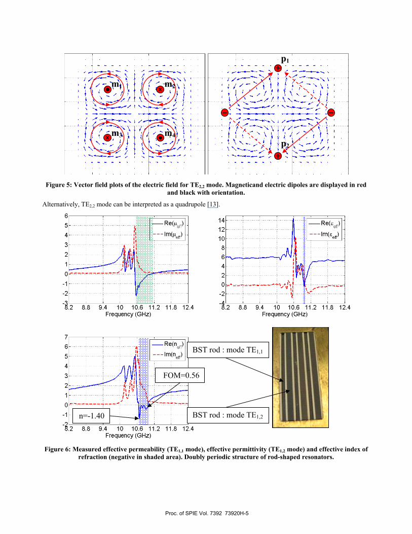
Figure 5: Vector field plots of the electric field for TE2,2 mode. Magneticand electric dipoles are displayed in red
and black with orientation.
Alternatively, TE2,2 mode can be interpreted as a quadrupole [13].
Figure 6: Measured effective permeability (TE1,1 mode), effective permittivity (TE1,2 mode) and effective index of
refraction (negative in shaded area). Doubly periodic structure of rod-shaped resonators.
m1 m2
m3 m4
p1
p2
BST rod : mode TE1,1
BST rod : mode TE1,2 n=-1.40
FOM=0.56
Proc. of SPIE Vol. 7392 73920H-5

2.4 Negative index with the TE1,1 and TE1,2 modes
For measurements a doubly periodic structure made of rod-shaped resonators is considered. The unit cell consists this time in two distinct rods whose dimensions (d1=0.88mm and d2=1.30mm) are chosen such that each resonates in a distinct mode, namely TE1,1 and TE1,2 around 10GHz.
Measurements were made in a waveguide setup with only six rods, three of cross-section lengths d1=0.88mm and three of cross-section lengths d2=1.30mm. Due to the inaccuracy of the sawing process size dispersion occurred leading to slightly different resonance frequencies for each rod and in turn to the oscillations witnessed on figure 6.
Around 10.6GHz a negative effective permeability is observed, figure 6 upper left, its minimum reaching –2.26. In a smaller frequency range above 10.6GHz a negative effective permittivity is also observed, figure 6 upper right, its minimum reaching –0.31. As a result a negative effective index occurs from 10.65GHz to 10.98GHz, a frequency range much wider than that of negative effective permittivity. This occurs because of losses, as shown by Lakhtakia [14], the condition for negative refraction in a lossy medium is:
( ) ( ) ( ) ( )Re .Im Im .Re 0r r r rε μ ε μ+ ≤
Therefore losses play an important part in the establishment of the negative effective index. The effective index minimum reaches –1.40 at 10.68GHz but at this frequency losses are important, while at 10.97GHz where the effective index is –0.21 the figure of merit (FOM) |Re(n)|/Im(n) reaches its maximum of 0.56, see figure 6. Away from resonances the material is seen to be lossless.
Effective permeability curves, figure 4 upper left, are well-described by Pendry’s model [15], that is:
( )( )
2,
2 2, ,
10
eff m n
eff m n m n
fi
μ ω ωμ ω ω γ ω
= +− −
Where fm,n is the oscillator strength, ωm,n the resonance frequency and γm,n the loss factor. At high frequencies this model accounts for the reduced effective permeability.
Effective permittivity curves, figure 4 upper right, are also well-described by Pendry’s model [15], that is:
( )( )
2,
2 2, ,
10
eff m n
eff m n m n
fi
ε ω ωε ω ω γ ω
= +− −
The main difference here resides in the fact that unlike μeff(0) the effective permittivity εeff(0) at low frequencies is different from one. For small filling fractions it is well-approximated by classic mixing formulas such as Maxwell Garnett [16].
3. 3D RESONATORS A periodic structure made of cylinder-shaped resonator, cylinders of finite height, arranged on a square lattice is considered. Rods are made of E5000, from TEMEX Ceramics, whose permittivity and loss tangent at 10GHz equal 78 and 1.3e-3, respectively [17]. Besides, this material was designed to be temperature stable in contrast to ferroelectric materials. Its temperature coefficient, which characterizes frequency shift with temperature, is between –3 to 9ppm/°C. Unlike previous 2D configurations only one resonator is measured this time, waveguide walls serve to simulate an equivalent medium of infinite extent in the transverse dimension. Foam is used to hold the resonator in a central position.
Proc. of SPIE Vol. 7392 73920H-6
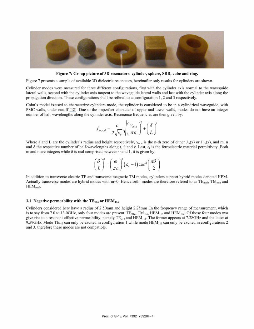
Figure 7: Group picture of 3D resonators: cylinder, sphere, SRR, cube and ring.
Figure 7 presents a sample of available 3D dielectric resonators, hereinafter only results for cylinders are shown.
Cylinder modes were measured for three different configurations, first with the cylinder axis normal to the waveguide lateral walls, second with the cylinder axis tangent to the waveguide lateral walls and last with the cylinder axis along the propagation direction. These configurations shall be refered to as configuration 1, 2 and 3 respectively.
Cohn’s model is used to characterize cylinders mode, the cylinder is considered to be in a cylindrical waveguide, with PMC walls, under cutoff [18]. Due to the imperfect character of upper and lower walls, modes do not have an integer number of half-wavelengths along the cylinder axis. Resonance frequencies are then given by:
2 2,
, , 2m n
m nr
ycfa Lδ
δπε
⎛ ⎞ ⎛ ⎞= +⎜ ⎟ ⎜ ⎟⎝ ⎠⎝ ⎠
Where a and L are the cylinder’s radius and height respectively, ym,n is the n-th zero of either Jm(x) or J’m(x), and m, n and δ the respective number of half-wavelengths along r, θ and z. Last, εr is the ferroelectric material permittivity. Both m and n are integers while δ is real comprised between 0 and 1, it is given by:
( )2 2
21 cos2rL c
δ ω πδεπ
⎛ ⎞ ⎛ ⎞ ⎛ ⎞= −⎜ ⎟ ⎜ ⎟ ⎜ ⎟⎝ ⎠ ⎝ ⎠ ⎝ ⎠
In addition to transverse electric TE and transverse magnetic TM modes, cylinders support hybrid modes denoted HEM. Actually transverse modes are hybrid modes with m=0. Henceforth, modes are therefore refered to as TEmnδ, TMm,n and HEMmnδ.
3.1 Negative permeability with the TE01δ or HEM11δ
Cylinders considered here have a radius of 2.50mm and height 2.25mm .In the frequency range of measurement, which is to say from 7.0 to 13.0GHz, only four modes are present: TE01δ, TM01δ, HEM11δ and HEM12δ. Of those four modes two give rise to a resonant effective permeability, namely TE01δ and HEM11δ. The former appears at 7.28GHz and the latter at 9.59GHz. Mode TE01δ can only be excited in configuration 1 while mode HEM11δ can only be excited in configurations 2 and 3, therefore these modes are not compatible.
Proc. of SPIE Vol. 7392 73920H-7

Figure 8: Magnetic field vector field plots for mode TE01δ (left) and mode HEM11δ (right), with their
corresponding magnetic dipole. Cylinder resonator is highlighted in black.
Vector field plots of TE01δ (magnetic field) and HEM11δ (magnetic field), as calculated with Ansoft HFSS, are shown on figure 8. These plots show that mode TE01δ radiates like a magnetic dipole oriented along the cylinder axis while mode HEM11δ radiates like a magnetic dipole oriented in the plane. The multipolar character of these modes explains effective permeability resonant behavior near their resonance frequencies.
3.2 Negative permittivity with the TM01δ or HEM12δ
Modes TM01δ and HEM12δ give rise to a resonant effective permittivity. The former appears at 11.31GHz and the latter at 9.96GHz. Mode TM01δ can only be excited in configuration 2 while mode HEM12δ can only be excited in configurations 1 and 3, therefore these modes are not compatible.
Figure 9: Electric field vector field plots for mode HEM12δ (left) and mode TM01δ (right), with their corresponding
electric dipole. Cylinder, in purple, is embedded in a metallic cavity. Cylinder resonator is highlighted in black.
Vector field plots of TM01δ (electric field) and HEM12δ (electric field) are shown on figure 9. These plots show that mode TM01δ radiates like an electric dipole oriented along the cylinder axis while mode HEM12δ radiates like an electric dipole oriented in the plane. The multipolar character of these modes explains effective permittivity resonant behavior near their resonance frequencies.
TE01δ HEM11δ
HEM12δ TM01δ
Y
Z
Y
X
Y
X
Y
Z
m
m
p
p
Proc. of SPIE Vol. 7392 73920H-8

3.3 Negative index with the HEM11δ and HEM12δ
To design a negative effective index two resonances of different character are needed, magnetic and electric resonances. Measurements have shown that in configuration 1 modes TE01δ and HEM12δ can be used, in configuration 2 modes HEM11δ and TM01δ and in configuration 3 modes HEM11δ and HEM12δ. For these particular geometric parameters (r=2.50mm, h=2.25mm) or resonant frequencies only the couple HEM11δ (9.59GHz) and HEM12δ (9.96GHz) can lead to a negative effective index, as shown in figure 10.
Figure 10: Measured effective permeability, effective permittivity and real and imaginary parts of the effective
index (negative in shaded area).
No oscillations are seen here because only one resonator is measured and therefore no dispersion can occur.
Around 9.7GHz a negative effective permeability is observed, figure 10 top, its minimum reaching –13.82. In a smaller frequency range above 10.0GHz a negative effective permittivity is also observed, figure 10 top, its minimum reaching –5.61. As a result a negative effective index occurs from 9.97GHz to 10.03GHz. The effective index minimum reaches –2.58 at 9.98GHz but at this frequency losses are important, while at 9.99GHz where the effective index is –1.77 the figure of merit (FOM) |Re(n)|/Im(n) reaches its maximum of 14.13, see figure 10. This proves that in all-dielectric metamaterials with little dispersion, as is standard with metallic metamaterials, losses can be lower.
With different geometric parameters resonance frequencies vary and can even cross each other, therefore other modes couple than HEM11δ and HEM12δ can be used to design a negative effective index. This can present advantages in the case where non-degenerate modes (TE01δ, TM01δ) are needed. However, configuration 3 has an additional merit as compared to configurations 1 and 2: it is polarization insensitive. To make sure that modes HEM11δ and HEM12δ can also be excited in a free-space environment an additional simulation, showing identical results, was realized, therefore this negative effective index scheme is also valid in free-space.
n=-2.58
FOM=14.13
Proc. of SPIE Vol. 7392 73920H-9

4. CONCLUSION In conclusion, it has been experimentally demonstrated, using ferroelectric materials in the microwave domain, that all-dielectric metamaterials can exhibit negative effective permeability or permittivity above specific resonances. With 2D resonators a 2-resonators scheme has been measured and shown to possess a negative effective index in the X-band. With 3D resonators the greater number of degrees of freedom has been shown to allow the design of a negative effective index with a 1-resonator scheme. Such a 1-resonator scheme, using higher-order modes, has been measured and shown to possess a negative effective index in the X-band. Additionally, using a single resonator setup, measurements have shown that a high figure of merit can be achieved (FOM=14.13) in all-dielectric metamaterials. Thus they can be considered good candidates to replace more lossy metallic structures. Besides, this low-loss structure is also polarization-insensitive. In conclusion, low-losses negative effective refractive indices materials can be built with an all-dielectric scheme.
REFERENCES
[1] Veselago, V., "The electrodynamics of substances with simultaneously negative values of ε and μ," Sov. Phys. Uspekhi 10, 509-514 (1968).
[2] Smith, D. R., Padilla, W. J., Vier, D. C., Nemat-Nasser, S. C. and Schultz, S., "Composite medium with simultaneously negative permeability and permittivity," Phys. Rev. Lett. 84, 4184-4187 (2000).
[3] Pendry, J. B., "Negative refraction makes a perfect lens," Phys. Rev. Lett. 85, 3966-3969 (2000). [4] Leonhardt, U., "Optical conformal mapping," Science 312, 1777-1780 (2006). [5] Pendry, J. B., Schurig, D. and Smith, D. R., "Controlling electromagnetic fields," Science 312, 1780-1782 (2006). [6] O’Brien, S. and Pendry J. B., "Photonic band-gap effects and magnetic activity in dielectric composites," J. Phys.:
Condens. Matter. 14, 4035-4044 (2002). [7] Kanté, B., de Lustrac, A., Lourtioz J-M. and Gadot, F., "Engineering resonances in infrared materials," Opt. Express
16, 6774-6784 (2008). [8] Tusseau-Nenez, S., Ganne, J-P., Maglione, M., Morell, A., Niepce, J-C. and Pate, M., "BST ceramics: Effect of
attrition milling on dielectric properties," J. Eur. Ceram. Soc. 24, 3003-3011 (2004). [9] Hakki, B. W. and Coleman, P. D., "A dielectric resonator method of measuring inductive capacities in the millimiter
range," IEEE Trans. Microwave Theory Tech. 8, 402-410 (1960). [10] Nicolson, A. M. and Ross, G. F., "Measurement of the intrinsic properties of materials by time-domain techniques,"
IEEE Trans. Instrumentation and Measurement 19, 377-382 (1970). Weir, W. B., "Automatic measurement of complex dielectric constant and permeability at microwave frequencies," Proc. IEEE 62, 33-36 (1974).
[11] Kajfez, D. and Guillon, P., [Dielectric resonators], Artech House, Dedham (1986). [12] Smith, D.R., Schultz, S., Markos, P. and Soukoulis, C. M., "Determination of effective permittivity and permeability
of metamaterials from reflection and transmission coefficients," Phys. Rev. B 65, 195104 (2002). Chen, H., Zhang, J., Bai, Y., Luo, Y., Ran, L., Jiang, Q. and Kong, J. A., "Experimental retrieval of the effective parameters of metamaterials based on a waveguide method," Opt. Exp. 14, 12944-12949 (2006).
[13] Koschny, T., Markos, P., Smith, D. R. and Soukoulis, C. M., "Resonant and antiresonant frequency dependence of the effective parameters of metamaterials," Phys. Rev. E 68, 065602 (2003).
[14] Lakhtakia, A., McCall, M. W. and Weiglhofer, W. S., "Negative phase velocity medium," Introduction to complex mediums for electromagnetics and optics, SPIE Press, Bellingham, WA (2003).
[15] Pendry, J. B., Holden, A. J., Robbins, D. J. and Stewart, W. J., "Magnetism from conductors and enhanced nonlinear phenomena," IEEE Trans. Microwave Theory Tech. 47, 2075-2084 (1999).
[16] Sihvola, A., [Electromagnetic mixing formulas and applications], The Institution of Electrical Engineers, London (1999).
[17] TEMEX Ceramics, www.temex-ceramics.com. [18] Cohn, S. B., "Microwave bandpass filters containing high-Q dielectric resonators," IEEE Trans. Microwave Theory
Tech. 16, 218-227 (1968).
Proc. of SPIE Vol. 7392 73920H-10


![Structural, dielectric, and ferroelectric properties of compositionally graded (Pb,La)TiO[sub 3] thin films with conductive LaNiO[sub 3] bottom electrodes](https://static.fdokumen.com/doc/165x107/633e60cf311de04f4d03b0af/structural-dielectric-and-ferroelectric-properties-of-compositionally-graded-pblatiosub.jpg)