A single-phase elastic hyperbolic metamaterial with ...
8
A single-phase elastic hyperbolic metamaterial with anisotropic mass density R. Zhu, 1,a) Y. Y. Chen, 1 Y. S. Wang, 2 G. K. Hu, 3 and G. L. Huang 1,b) 1 Department of Mechanical and Aerospace Engineering, University of Missouri, Columbia, Missouri 65211, USA 2 Institute of Engineering Mechanics, Beijing Jiaotong University, Beijing, People’s Republic of China 3 School of Aerospace Engineering, Beijing Institute of Technology, Beijing, People’s Republic of China (Received 16 October 2015; revised 28 January 2016; accepted 27 February 2016; published online 30 June 2016) Wave propagation can be manipulated at a deep subwavelength scale through the locally resonant metamaterial that possesses unusual effective material properties. Hyperlens due to metamaterial’s anomalous anisotropy can lead to superior-resolution imaging. In this paper, a single-phase elastic metamaterial with strongly anisotropic effective mass density has been designed. The proposed metamaterial utilizes the independently adjustable locally resonant motions of the subwavelength- scale microstructures along the two principal directions. High anisotropy in the effective mass densities obtained by the numerical-based effective medium theory can be found and even have opposite signs. For practical applications, shunted piezoelectric elements are introduced into the microstructure to tailor the effective mass density in a broad frequency range. Finally, to validate the design, an elastic hyperlens made of the single-phase hyperbolic metamaterial is proposed with subwavelength longitudinal wave imaging illustrated numerically. The proposed single-phase hyperbolic metamaterial has many promising applications for high resolution damage imaging in nondestructive evaluation and structural health monitoring. V C 2016 Acoustical Society of America. [http://dx.doi.org/10.1121/1.4950728] [MRH] Pages: 3303–3310 I. INTRODUCTION Metamaterials, with engineered subwavelength-scale microstructures, have exhibited many unique and useful abil- ities for wave control. Among them, super-resolution imag- ing is one of the most attractive abilities even since it was first discovered. Based on the negative index of refraction of electromagnetic (EM) metamaterials, Pendry 1 was the first to theoretically investigated super-resolution imaging by using the so-called “superlens,” which has the ability of not only focusing the propagating waves but also amplifying the evanescent waves. Since the fine details of the imaging object corresponding to the high spatial frequency compo- nents are carried by the evanescent waves, imaging with re- solution beyond the diffraction limit can be obtained by using superlens technology. 2 Inspired by Pendry’s pioneer- ing work, many superlens designs have been proposed not only for EM waves but also for acoustic waves. 3–8 It is observed that the subwavelength images obtained by a superlens are typically limited to the near field of the lens due to the fact that it can only amplify the evanescent waves but not change their decaying behavior. A hyperlens, on the other hand, can not only carry the subwavelength in- formation contained within the evanescent waves across the lens, but also magnify it, thereby converting it to propagating waves such that the information travels to the far-field outside the lens. Basically, the realization of the hyperlens for far-field super-resolution acoustic imaging relies on the elliptical or hyperbolic equifrequency contour (EFC) which allows for very high spatial frequency components carrying the detailed information from objects. Christensen et al. 9,10 designed an acoustic metamaterial formed by layers of per- forated plates and experimentally demonstrated its hyper- bolic dispersion and subwavelength acoustic imaging based on the anisotropic lattices of scatterers. Anisotropic dynamic mass density provides one of the most practical options to fulfill the material requirement of elliptical or hyperbolic EFC(Refs. 11–15). Li et al. 11 designed an acoustic metama- terial with strongly anisotropic mass density from alternating layers of brass fins and air. An acoustic hyperlens with ellip- tical EFC was fabricated by using the acoustic metamaterial and subwavelength acoustic images with a k/6.8 – k/4.1 re- solution were experimentally obtained. Shen et al. 12 designed an acoustic hyperbolic metamaterial with the den- sity being positive in one direction and negative in the or- thogonal direction. Subwavelength imaging (k/4.7) and partial focusing for acoustic waves was experimentally dem- onstrated in a broad frequency range. Elastic metamaterials (EMMs), with properly designed locally resonant (LR) microstructures, can behave as effective materials with extraordinary material properties that are not found in nature, such as negative mass density, 16–18 negative elastic modulus, 19 and anisotropic mass density. 20–23 With the abnormal effective material properties, EMMs have been given unique subwavelength-scale wave manipulation abilities such as flat lens wave focusing, 24 90-deg elastic wave bending, 25 and negative refractions. 26,27 Subwavelength imaging for elastic waves has also been investigated, although not as a) Present address: Department of Aeronautics and Astronautics, University of Washington, Seattle, WA 98195. Electronic mail: [email protected]. b) Author to whom correspondence should be addressed. Also at: Institute of Engineering Mechanics, Beijing Jiaotong University, Beijing, People’s Republic of China. Electronic mail: [email protected] J. Acoust. Soc. Am. 139 (6), June 2016 V C 2016 Acoustical Society of America 3303 0001-4966/2016/139(6)/3303/8/$30.00
-
Upload
khangminh22 -
Category
Documents
-
view
0 -
download
0
Transcript of A single-phase elastic hyperbolic metamaterial with ...

A single-phase elastic hyperbolic metamaterial with anisotropicmass density
R. Zhu,1,a) Y. Y. Chen,1 Y. S. Wang,2 G. K. Hu,3 and G. L. Huang1,b)
1Department of Mechanical and Aerospace Engineering, University of Missouri, Columbia, Missouri 65211, USA2Institute of Engineering Mechanics, Beijing Jiaotong University, Beijing, People’s Republic of China3School of Aerospace Engineering, Beijing Institute of Technology, Beijing, People’s Republic of China
(Received 16 October 2015; revised 28 January 2016; accepted 27 February 2016; published online30 June 2016)
Wave propagation can be manipulated at a deep subwavelength scale through the locally resonant
metamaterial that possesses unusual effective material properties. Hyperlens due to metamaterial’s
anomalous anisotropy can lead to superior-resolution imaging. In this paper, a single-phase elastic
metamaterial with strongly anisotropic effective mass density has been designed. The proposed
metamaterial utilizes the independently adjustable locally resonant motions of the subwavelength-
scale microstructures along the two principal directions. High anisotropy in the effective mass
densities obtained by the numerical-based effective medium theory can be found and even have
opposite signs. For practical applications, shunted piezoelectric elements are introduced into the
microstructure to tailor the effective mass density in a broad frequency range. Finally, to validate
the design, an elastic hyperlens made of the single-phase hyperbolic metamaterial is proposed with
subwavelength longitudinal wave imaging illustrated numerically. The proposed single-phase
hyperbolic metamaterial has many promising applications for high resolution damage imaging in
nondestructive evaluation and structural health monitoring. VC 2016 Acoustical Society of America.
[http://dx.doi.org/10.1121/1.4950728]
[MRH] Pages: 3303–3310
I. INTRODUCTION
Metamaterials, with engineered subwavelength-scale
microstructures, have exhibited many unique and useful abil-
ities for wave control. Among them, super-resolution imag-
ing is one of the most attractive abilities even since it was
first discovered. Based on the negative index of refraction of
electromagnetic (EM) metamaterials, Pendry1 was the first
to theoretically investigated super-resolution imaging by
using the so-called “superlens,” which has the ability of not
only focusing the propagating waves but also amplifying the
evanescent waves. Since the fine details of the imaging
object corresponding to the high spatial frequency compo-
nents are carried by the evanescent waves, imaging with re-
solution beyond the diffraction limit can be obtained by
using superlens technology.2 Inspired by Pendry’s pioneer-
ing work, many superlens designs have been proposed not
only for EM waves but also for acoustic waves.3–8
It is observed that the subwavelength images obtained
by a superlens are typically limited to the near field of the
lens due to the fact that it can only amplify the evanescent
waves but not change their decaying behavior. A hyperlens,
on the other hand, can not only carry the subwavelength in-
formation contained within the evanescent waves across the
lens, but also magnify it, thereby converting it to propagating
waves such that the information travels to the far-field
outside the lens. Basically, the realization of the hyperlens
for far-field super-resolution acoustic imaging relies on the
elliptical or hyperbolic equifrequency contour (EFC) which
allows for very high spatial frequency components carrying
the detailed information from objects. Christensen et al.9,10
designed an acoustic metamaterial formed by layers of per-
forated plates and experimentally demonstrated its hyper-
bolic dispersion and subwavelength acoustic imaging based
on the anisotropic lattices of scatterers. Anisotropic dynamic
mass density provides one of the most practical options to
fulfill the material requirement of elliptical or hyperbolic
EFC(Refs. 11–15). Li et al.11 designed an acoustic metama-
terial with strongly anisotropic mass density from alternating
layers of brass fins and air. An acoustic hyperlens with ellip-
tical EFC was fabricated by using the acoustic metamaterial
and subwavelength acoustic images with a k/6.8 – k/4.1 re-
solution were experimentally obtained. Shen et al.12
designed an acoustic hyperbolic metamaterial with the den-
sity being positive in one direction and negative in the or-
thogonal direction. Subwavelength imaging (k/4.7) and
partial focusing for acoustic waves was experimentally dem-
onstrated in a broad frequency range.
Elastic metamaterials (EMMs), with properly designed
locally resonant (LR) microstructures, can behave as effective
materials with extraordinary material properties that are not
found in nature, such as negative mass density,16–18 negative
elastic modulus,19 and anisotropic mass density.20–23 With the
abnormal effective material properties, EMMs have been given
unique subwavelength-scale wave manipulation abilities such
as flat lens wave focusing,24 90-deg elastic wave bending,25
and negative refractions.26,27 Subwavelength imaging for
elastic waves has also been investigated, although not as
a)Present address: Department of Aeronautics and Astronautics, University of
Washington, Seattle, WA 98195. Electronic mail: [email protected])Author to whom correspondence should be addressed. Also at: Institute of
Engineering Mechanics, Beijing Jiaotong University, Beijing, People’s
Republic of China. Electronic mail: [email protected]
J. Acoust. Soc. Am. 139 (6), June 2016 VC 2016 Acoustical Society of America 33030001-4966/2016/139(6)/3303/8/$30.00
intensively as for EM and acoustic waves. Zhou et al.28 pro-
posed a solid phononic crystal superlens capable of producing
both negative refraction to focus propagating elastic waves and
surface states to amplify evanescent waves. Lee et al.29
designed an elastic plate hyperlens with alternating layers of
aluminum and air which exhibited very strong anisotropy in
elastic stiffness and produces an elliptical EFC. Oh et al.30
experimentally demonstrated subwavelength imaging for elas-
tic waves with a lens exhibiting hyperbolic EFC which results
from the different deformation mechanisms along the two prin-
cipal directions of the coiling-up microstructure in the unit cell.
However, few research about elastic hyperlens design based on
subwavelength-scale EMM with anisotropic mass density has
been reported. Unlike anisotropic dynamic mass density in
acoustic metamaterials, anisotropic mass density in EMMs can
only be engineered by using anisotropic LR inclusions. Milton
and Willis20 first proposed a two-dimensional (2-D) spring-
mass LR model which shows that the effective mass density
could become anisotropic. Huang and Sun21 systematically
investigated the dynamic behavior of the 2-D LR mass-spring
system and demonstrated that the effective mass density is
actually a second-order tensor. Colquitt et al.31,32 studied the
dynamic anisotropy of lattice systems in vector problems of
elasticity and the interaction of elastic waves with material
with microstructure outside the standard homogenization re-
gime. Antonakakis et al.33 developed a continuum model for
EMMs at high frequency range beyond long wavelength re-
gime. Zhu et al.22 proposed and experimentally validated a
solid microstructure design of a continuum anisotropic EMM
with complex resonant inclusions embedded in a solid plate
which exhibited strong anisotropic mass density.
In this paper, we propose a novel microstructure design
of a single-phase EMM with anisotropic dynamic mass den-
sity. The anisotropy of the effective mass density is caused by
the decoupled resonant motions along the two principal in-
plane directions. Single-phase microstructure design provides
manufacturing feasibility particularly for plate-like structures.
Effective material properties of the proposed EMM are calcu-
lated based on the numerical-based effective medium method
and the hyperbolic EFCs of the EMM are obtained through
the analytical derivation of wave propagation in the effective
elastic medium with anisotropic mass densities. For practical
applications, shunted piezoelectric elements are integrated
into the microstructure to tune the effective mass density in a
broad frequency range. Finally, an elastic hyperlens for a lon-
gitudinal elastic wave is demonstrated and super-resolution
phenomenon (k/3) is observed numerically.
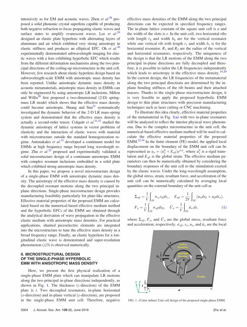
II. MICROSTRUCTURAL DESIGNOF THE SINGLE-PHASE HYPERBOLICEMM WITH ANISOTROPIC MASS DENSITY
Here, we present the first physical realization of a
single-phase EMM plate which can manipulate LR motions
along the two principal in-plane directions independently, as
shown in Fig. 1. The thickness (z-direction) of the EMM
plate is t. Two decoupled resonators, in-plane horizontal
(x-direction) and in-plane vertical (y-direction), are proposed
in the single-phase EMM unit cell. Therefore, negative
effective mass densities of the EMM along the two principal
directions can be expected in specified frequency ranges.
The in-plane lattice constant of the square unit cell is a and
the width of the slots is s. In the unit cell, two horizontal ribs
with length rh and width bh are for the vertical resonator
while one vertical rib with length rv and width bv is for the
horizontal resonator. R1 and R2 are the radius of the vertical
and horizontal resonators, respectively. The uniqueness of
the design is that the LR motions of the EMM along the two
principal in-plane directions are fully decoupled and there-
fore, it is possible to tailor the LR frequencies independently
which leads to anisotropy in the effective mass density.19,20
In the current design, the LR frequencies of the metamaterial
along the two principal directions are determined by the in-
plane bending stiffness of the rib beams and their attached
masses. Thanks to the single-phase microstructure design, it
is very feasible to apply the proposed hyperbolic EMM
design to thin plate structures with precision manufacturing
techniques such as laser cutting or CNC machining.
To illustrate this idea clearly, effective material properties
of the metamaterial in Fig. 1(a) with two in-plane resonators
will be analyzed to reflect the interior physical wave phenom-
ena. Due to the complex microstructure in the unit cell, the
numerical-based effective medium method will be used to cal-
culate the effective material properties of the proposed
EMM.22,34 In the finite element (FE) model, the applied local
displacement on the boundary of the EMM unit cell can be
represented as ua ¼ ðu0a þ EabÞeixt, where u0
a is a rigid trans-
lation and Eab is the global strain. The effective medium pa-
rameters can then be numerically obtained by considering the
boundary responses of the unit cell to the stimulation exerted
by the elastic waves. Under the long-wavelength assumption,
the global stress, strain, resultant force, and acceleration of the
unit cell can be numerically calculated by averaging local
quantities on the external boundary of the unit cell as
Rab ¼1
V
ð@V
racxbdsc; Eab ¼1
2V
ð@V
uadsb þ ubdsað Þ;
Fa ¼1
V
ð@V
rabdsb; €Ua ¼1
V
ð@V
€ua ds; (1)
where Rab, Fa, and €Ua are the global stress, resultant force
and acceleration, respectively. rab, xa, ua, and €ua are the local
FIG. 1. (Color online) Unit cell design of the proposed single-phase EMM.
3304 J. Acoust. Soc. Am. 139 (6), June 2016 Zhu et al.

stress, position vector, displacement and acceleration fields,
respectively. Specifically, the anisotropic effective mass den-
sity of the single-phase EMM along the x and y principal
directions can be determined based on the following relation:
Fx
Fy
� �¼ �x2V
qxx 0
0 qyy
" #Ux
Uy
� �; (2)
where Ux and Uy are the global displacement fields along the
x and y directions, respectively. V denotes the volume of the
unit cell. As an example, the dynamic anisotropic mass den-
sities of the EMM along the x and y in-plane principal direc-
tions as functions of frequencies are plotted as a solid curve
and a dash curve in Fig. 2(a), respectively. Due to the very
small thickness of the EMM plate, 2-D FE simulation with
plane stress assumption is a good approximation and a com-
putational efficient approach for the EMM analysis. In the
figure, the effective mass densities are normalized with the
average static mass density of the unit cell. The unit cell’s
geometric and material properties used in the calculation are
listed in Table I.
As shown in Fig. 2(a), obvious differences between the
values of qeffxx and qeff
yy can be found after f¼ 10 kHz, which
is due to the different LR frequencies of the unit cell along xand y directions being f LR
x ¼ 15:23 kHz and f LRy ¼ 15:8 kHz,
respectively, as shown in the zoom-in Fig. 2(b). The mode
shapes at these two resonant frequencies are also demon-
strated in Fig. 2(b) where the independent in-plane resonant
motions of the horizontal and vertical resonators can be
observed. Furthermore, different signs for qeffxx and qeff
yy can
be observed in two frequency ranges (15.23, 15.6 kHz) and
(15.8, 17.25 kHz). Negative qeffxx and positive qeff
yy is found in
the first of the two frequency ranges while the opposite case
is observed in the second range. The EMM with positive and
negative mass densities along different in-plane principal
directions in those frequency ranges could have hyperbolic
dispersion curves and therefore, can be used for elastic
hyperlens. The effective Young’s and shear modulus of the
single-phase EMM can also be calculated based on the effec-
tive model,34 which on the contrary are almost constant val-
ues of Eeff ¼ 104 GPa and veff ¼ 0:285, respectively.
To characterize in-plane wave propagation in the plate-
like EMM with anisotropic mass densities, the in-plane
dispersion relations are derived based on the calculated
effective material properties. The equations of motion for a
2-D homogenized medium with the anisotropic mass density
tensor can be written as
q@2u
@t2¼ M � Gð Þrr � u þ Gr2u; (3)
where q is the anisotropic mass density tensor; u is the dis-
placement vector; M and G are the effective P-wave modu-
lus and effective shear modulus of the EMM, respectively.
In order to separate the longitudinal and transverse wave
modes, the displacement vector is expressed via Helmholtz
decomposition as the gradient of a scalar and the curl of a
zero divergence vector:35
u ¼ rUþr� H ; r � H ¼ 0; (4)
where U and H are scalar and vector potentials, respec-
tively. Then, the equations of motion in Eq. (3) can be
rewritten as
q r @2U@t2þr� @
2H
@t2
� �¼ M � Gð Þrr
� rUþr� Hð Þ
þ Gr2 rUþr� Hð Þ:(5)
By conducting simplified tensor and vector operations, lon-
gitudinal and transverse wave equations of the motion can
be separated as
qr @2U@t2�r Mr2Uð Þ ¼ 0; (6a)
FIG. 2. (a) (Color online) Anisotropic
effective mass density of the proposed
single-phase EMM. (b) Zoom-in figure at
the resonant frequency range and the two
resonant modes at 15.23 and 15.8 kHz.
TABLE I. Unit cell geometrical and material parameters of the EMM.
Geometrical properties (in mm) Material properties (stainless steel)
s 0.5 Mass density 7850 kg/m3
rh 2.1 Young’s modulus 200 GPa
rv 4.1 Poisson’s ratio 0.3
bh 0.65
bv 2
R1 5.7
R2 2.25
a 20
t 1.5
J. Acoust. Soc. Am. 139 (6), June 2016 Zhu et al. 3305
qr� @2H
@t2� Gr2 r� Hð Þ ¼ 0: (6b)
In this study, we focus on the longitudinal wave propagation
in the medium with anisotropic mass densities. Therefore,
after multiplying the reciprocal mass density tensor, ðqÞ�1
and taking the divergence, r � ð�Þ, to Eq. (6a), we obtain the
following relation:
@2 r2Uð Þ@t2
�r � q� ��1r Mr2Uð Þh i
¼ 0: (7)
Since the x and y axes are the two principal directions of
the EMM, only diagonal elements of the anisotropic mass
density tensor and its reciprocal tensor remain as q
¼ qeffxx 0
0 qeffyy
� �and ðqÞ�1 ¼ 1=qeff
xx 0
0 1=qeffyy
� �, respec-
tively. Therefore, Eq. (7) can be rewritten as
M
qeffxx
@2 r2Uð Þ@x2
þ M
qeffyy
@2 r2Uð Þ@y2
¼ @2 r2Uð Þ@t2
: (8)
By assuming the longitudinal plane wave with
U ¼ U0 exp ð�ikp � r � ixtÞ, where k
pand r are the
longitudinal wave vector and displacement vector, respec-
tively, Eq. (8) can be rewritten as
kpxxð Þ2
qeffxx
þkp
yy
� �2
qeffyy
¼ x2
M; (9)
where kpxx and kp
yy are the longitudinal wave vector compo-
nents along the x and y principal directions, respectively. It
can be found that the dispersion relation for the longitudinal
wave propagating in the EMM with anisotropic mass density
is the same as that for acoustic waves in anisotropic acoustic
metamaterial.36
The equifrequency contours (EFCs) of the proposed
single-phase EMM at f¼ 15.3 kHz and at f¼ 16.3 kHz are
obtained by using Eq. (9), as shown in Fig. 3. The effective
mass densities along the x and y principal directions at both
frequencies can be obtained from Fig. 2 and the effective P-
wave modulus M can be obtained based on the relation
M ¼ K þ ð4=3ÞG.
It can be seen in Fig. 3 that both EFCs demonstrate the
hyperbolic shape as expected, which means the longitudinal
elastic wave can propagate only along one principal direc-
tion where the effective mass density is positive and is for-
bidden in the other principal direction with negative
effective mass density. In order to validate the anisotropic
mass density and the directional wave propagation, the lon-
gitudinal wave fields inside a 2-D array of the proposed
EMM unit cells at f¼ 15.3 kHz and f¼ 16.3 kHz are plotted
in Figs. 4(a) and 4(b), respectively. The longitudinal waves
are simulated by applying nodal forces normal to the circum-
ference of a small circle positioned at the center of the array.
A full-scale harmonic elastic wave simulation is performed
using the commercial FE software COMSOL. The longitudi-
nal wave field results are obtained by taking the divergence
of the simulated displacement fields. Longitudinal wave
propagating only along the y-axis is found at f¼ 15.3 kHz
since the qeffxx is negative, as shown in Fig. 4(a) while longitu-
dinal wave propagating only along the x axis is found at
f¼ 16.3 kHz since the qeffyy becomes negative, as shown in
Fig. 4(b). It is also observed that the wavelength in Fig. 4(a)
is smaller than that in Fig. 4(b) because the positive qeffyy at
f¼ 15.3 kHz is larger than the positive qeffxx at f¼ 16.3 kHz,
which can be found in Fig. 2(b). The reflections in Fig. 4 are
the result of the material mismatches between the EMM
array and the surrounding steel medium.
FIG. 3. (Color online) EFC of the proposed single-phase EMM calculated at
f¼ 15.3 kHz and f¼ 16.3 kHz.
FIG. 4. (Color online) Longitudinal
elastic wave propagations in the
single-phase EMM at (a) f¼ 15.3 kHz
and (b) f¼ 16.3 kHz.
3306 J. Acoust. Soc. Am. 139 (6), June 2016 Zhu et al.
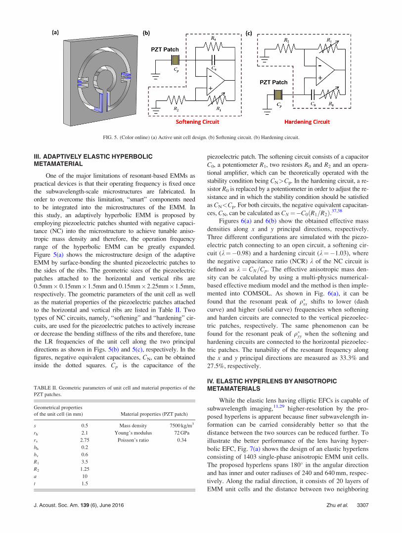
III. ADAPTIVELY ELASTIC HYPERBOLICMETAMATERIAL
One of the major limitations of resonant-based EMMs as
practical devices is that their operating frequency is fixed once
the subwavelength-scale microstructures are fabricated. In
order to overcome this limitation, “smart” components need
to be integrated into the microstructures of the EMM. In
this study, an adaptively hyperbolic EMM is proposed by
employing piezoelectric patches shunted with negative capaci-
tance (NC) into the microstructure to achieve tunable aniso-
tropic mass density and therefore, the operation frequency
range of the hyperbolic EMM can be greatly expanded.
Figure 5(a) shows the microstructure design of the adaptive
EMM by surface-bonding the shunted piezoelectric patches to
the sides of the ribs. The geometric sizes of the piezoelectric
patches attached to the horizontal and vertical ribs are
0:5mm� 0:15mm�1:5mm and 0:15mm�2:25mm�1:5mm,
respectively. The geometric parameters of the unit cell as well
as the material properties of the piezoelectric patches attached
to the horizontal and vertical ribs are listed in Table II. Two
types of NC circuits, namely, “softening” and “hardening” cir-
cuits, are used for the piezoelectric patches to actively increase
or decrease the bending stiffness of the ribs and therefore, tune
the LR frequencies of the unit cell along the two principal
directions as shown in Figs. 5(b) and 5(c), respectively. In the
figures, negative equivalent capacitances, CN, can be obtained
inside the dotted squares. Cp is the capacitance of the
piezoelectric patch. The softening circuit consists of a capacitor
C0, a potentiometer R1, two resistors R0 and R2 and an opera-
tional amplifier, which can be theoretically operated with the
stability condition being CN>Cp. In the hardening circuit, a re-
sistor R0 is replaced by a potentiometer in order to adjust the re-
sistance and in which the stability condition should be satisfied
as CN<Cp. For both circuits, the negative equivalent capacitan-
ces, CN, can be calculated as CN¼�C0ðR1=R2Þ:37,38
Figures 6(a) and 6(b) show the obtained effective mass
densities along x and y principal directions, respectively.
Three different configurations are simulated with the piezo-
electric patch connecting to an open circuit, a softening cir-
cuit (k¼�0.98) and a hardening circuit (k¼�1.03), where
the negative capacitance ratio (NCR) k of the NC circuit is
defined as k ¼ CN=Cp. The effective anisotropic mass den-
sity can be calculated by using a multi-physics numerical-
based effective medium model and the method is then imple-
mented into COMSOL. As shown in Fig. 6(a), it can be
found that the resonant peak of q�xx shifts to lower (dash
curve) and higher (solid curve) frequencies when softening
and harden circuits are connected to the vertical piezoelec-
tric patches, respectively. The same phenomenon can be
found for the resonant peak of q�yy when the softening and
hardening circuits are connected to the horizontal piezoelec-
tric patches. The tunability of the resonant frequency along
the x and y principal directions are measured as 33.3% and
27.5%, respectively.
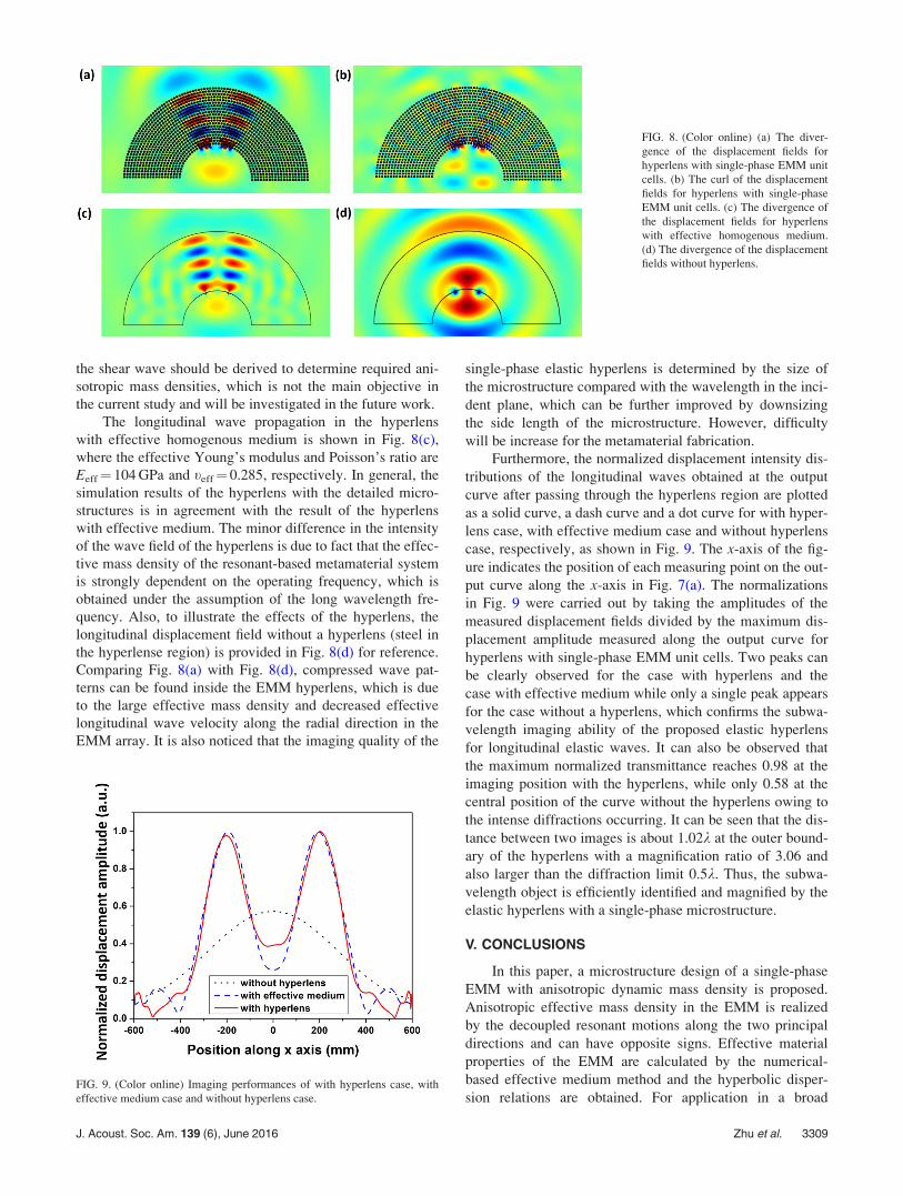
IV. ELASTIC HYPERLENS BY ANISOTROPICMETAMATERIALS
While the elastic lens having elliptic EFCs is capable of
subwavelength imaging,11,29 higher-resolution by the pro-
posed hyperlens is apparent because finer subwavelength in-
formation can be carried considerably better so that the
distance between the two sources can be reduced further. To
illustrate the better performance of the lens having hyper-
bolic EFC, Fig. 7(a) shows the design of an elastic hyperlens
consisting of 1403 single-phase anisotropic EMM unit cells.
The proposed hyperlens spans 180� in the angular direction
and has inner and outer radiuses of 240 and 640 mm, respec-
tively. Along the radial direction, it consists of 20 layers of
EMM unit cells and the distance between two neighboring
FIG. 5. (Color online) (a) Active unit cell design. (b) Softening circuit. (b) Hardening circuit.
TABLE II. Geometric parameters of unit cell and material properties of the
PZT patches.
Geometrical properties
of the unit cell (in mm) Material properties (PZT patch)
s 0.5 Mass density 7500 kg/m3
rh 2.1 Young’s modulus 72 GPa
rv 2.75 Poisson’s ratio 0.34
bh 0.2
bv 0.6
R1 3.5
R2 1.25
a 10
t 1.5
J. Acoust. Soc. Am. 139 (6), June 2016 Zhu et al. 3307
layers of EMM unit cells is a¼ 20 mm which is the same as
the distance between two neighboring unit cells along the
circumferential direction. In order to demonstrate the subwa-
velength imaging ability of the proposed elastic hyperlens,
full-scale harmonic elastic wave simulations using
COMSOL are performed. The dimensions of the host me-
dium made of steel (q¼ 7850 kg/m3, E¼ 200 GPa and
t¼ 0.3) are 1600 mm� 1000 mm. Perfectly matched layers
(PMLs), highlighted in Fig. 7(a), are applied to the bounda-
ries of the simulation region to eliminate any unwanted
reflections. Figures 7(b) and 7(c) show the zoomed-in pic-
tures of the meshed hyperlens and the single-phase EMM
unit cell, respectively. The simulation frequency is chosen at
f¼ 15.3 kHz where the effective mass density is positive
along the radial direction but negative along the angular
direction as predicted in Fig. 2. As shown in Fig. 7(a), two
omnidirectional longitudinal wave sources are simulated
by applying nodal forces normal to the circumferences of
two small circles which have a radius of only 2 mm and
are separated by ð1=3Þk, where k is the wavelength of the
longitudinal elastic wave in steel. The distance between the
sources and the first layer of the EMM unit cells along the
radial direction is 20 mm. The input waves from the two lon-
gitudinal wave sources are expected to enter the hyperlens
region and be guided along the radial direction. The output
wave field will be measured along a predefined curve which
is parallel to the last layer of the hyperlens with the same dis-
tance of 20 mm between them. The predefined curve is high-
lighted, as shown in Fig. 7(a). Note that the studied
longitudinal wave wavelength k is much larger than the size
of the single-phase EMM unit cell a at k¼ 18a. To clearly
explain hyperbolic wave dispersion mechanism, simulations
are also performed on the hyperlens made of the homogene-
ous medium with the same geometric shape and effective
mass densities along the radial and angular directions as
qr ¼ 23 500 kg/m3 and qh¼�68 600 kg/m3, respectively,
which are obtained from the results of the numerical-based
effective medium model at 15.3 kHz.
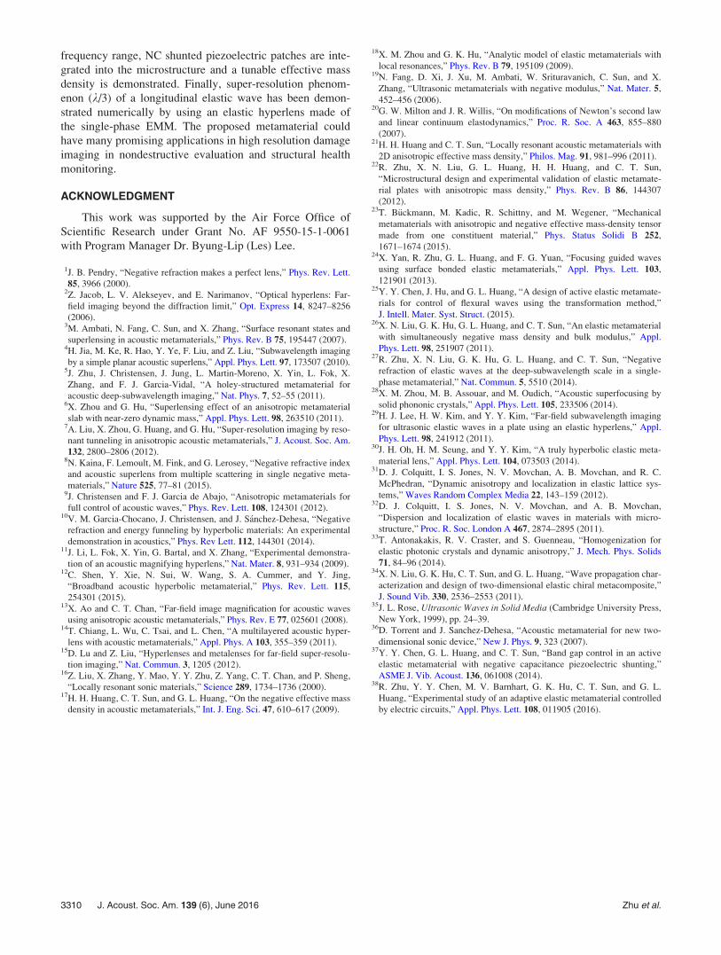
The in-plane longitudinal and the transverse wave prop-
agations in the hyperlenses with single-phase EMM are
shown in Figs. 8(a) and 8(b), respectively. The divergence
and curl of the simulated displacement fields are plotted to
separate the longitudinal and transverse wave fields, respec-
tively.27 As shown in Fig. 8(a), the longitudinal waves prop-
agate along the radial direction of the hyperlens and two
separate wave propagation channels inside the hyperlens
region can be clearly observed. At the outer boundary of the
hyperlens, the distance between two sources is enlarged.
Once the magnified feature is larger than the diffraction
limit, then we can observe the subwavelength features of the
object in the far field. In Fig. 8(b), weak transverse waves
are generated at the interface between the hyperbolic EMM
and the steel matrix near the wave sources due to the wave
mode conversion. However, the transverse wavenumber
along the radial direction of the hyperlens is an imaginary
value due to the band gap of the shear wave mode which is
generated by the negative effective mass density along the
angular direction at 15.3 kHz,21 and therefore the transverse
wave cannot propagate along the radial direction, as shown
in Fig. 8(b). It should be mentioned that the proposed aniso-
tropic EMM could be also extended for the hyperlens design
of the shear wave because propagations of both the longitu-
dinal and shear waves can be controlled by independently
adjustable effective mass densities along two principle direc-
tions. However, in order to do that, a hyperlens model for
FIG. 6. (Color online) Effective mass
densities of the active EMM along (a)
x and (b) y directions.
FIG. 7. (Color online) (a) Design of elastic hyperlens. (b) Zoom-in meshed
hyperlens with two omnidirectional longitudinal wave sources. (c) Zoom-in
meshed EMM unit cell.
3308 J. Acoust. Soc. Am. 139 (6), June 2016 Zhu et al.
the shear wave should be derived to determine required ani-
sotropic mass densities, which is not the main objective in
the current study and will be investigated in the future work.
The longitudinal wave propagation in the hyperlens
with effective homogenous medium is shown in Fig. 8(c),
where the effective Young’s modulus and Poisson’s ratio are
Eeff¼ 104 GPa and teff¼ 0.285, respectively. In general, the
simulation results of the hyperlens with the detailed micro-
structures is in agreement with the result of the hyperlens
with effective medium. The minor difference in the intensity
of the wave field of the hyperlens is due to fact that the effec-
tive mass density of the resonant-based metamaterial system
is strongly dependent on the operating frequency, which is
obtained under the assumption of the long wavelength fre-
quency. Also, to illustrate the effects of the hyperlens, the
longitudinal displacement field without a hyperlens (steel in
the hyperlense region) is provided in Fig. 8(d) for reference.
Comparing Fig. 8(a) with Fig. 8(d), compressed wave pat-
terns can be found inside the EMM hyperlens, which is due
to the large effective mass density and decreased effective
longitudinal wave velocity along the radial direction in the
EMM array. It is also noticed that the imaging quality of the
single-phase elastic hyperlens is determined by the size of
the microstructure compared with the wavelength in the inci-
dent plane, which can be further improved by downsizing
the side length of the microstructure. However, difficulty
will be increase for the metamaterial fabrication.
Furthermore, the normalized displacement intensity dis-
tributions of the longitudinal waves obtained at the output
curve after passing through the hyperlens region are plotted
as a solid curve, a dash curve and a dot curve for with hyper-
lens case, with effective medium case and without hyperlens
case, respectively, as shown in Fig. 9. The x-axis of the fig-
ure indicates the position of each measuring point on the out-
put curve along the x-axis in Fig. 7(a). The normalizations
in Fig. 9 were carried out by taking the amplitudes of the
measured displacement fields divided by the maximum dis-
placement amplitude measured along the output curve for
hyperlens with single-phase EMM unit cells. Two peaks can
be clearly observed for the case with hyperlens and the
case with effective medium while only a single peak appears
for the case without a hyperlens, which confirms the subwa-
velength imaging ability of the proposed elastic hyperlens
for longitudinal elastic waves. It can also be observed that
the maximum normalized transmittance reaches 0.98 at the
imaging position with the hyperlens, while only 0.58 at the
central position of the curve without the hyperlens owing to
the intense diffractions occurring. It can be seen that the dis-
tance between two images is about 1.02k at the outer bound-
ary of the hyperlens with a magnification ratio of 3.06 and
also larger than the diffraction limit 0.5k. Thus, the subwa-
velength object is efficiently identified and magnified by the
elastic hyperlens with a single-phase microstructure.
V. CONCLUSIONS
In this paper, a microstructure design of a single-phase
EMM with anisotropic dynamic mass density is proposed.
Anisotropic effective mass density in the EMM is realized
by the decoupled resonant motions along the two principal
directions and can have opposite signs. Effective material
properties of the EMM are calculated by the numerical-
based effective medium method and the hyperbolic disper-
sion relations are obtained. For application in a broad
FIG. 8. (Color online) (a) The diver-
gence of the displacement fields for
hyperlens with single-phase EMM unit
cells. (b) The curl of the displacement
fields for hyperlens with single-phase
EMM unit cells. (c) The divergence of
the displacement fields for hyperlens
with effective homogenous medium.
(d) The divergence of the displacement
fields without hyperlens.
FIG. 9. (Color online) Imaging performances of with hyperlens case, with
effective medium case and without hyperlens case.
J. Acoust. Soc. Am. 139 (6), June 2016 Zhu et al. 3309
frequency range, NC shunted piezoelectric patches are inte-
grated into the microstructure and a tunable effective mass
density is demonstrated. Finally, super-resolution phenom-
enon (k/3) of a longitudinal elastic wave has been demon-
strated numerically by using an elastic hyperlens made of
the single-phase EMM. The proposed metamaterial could
have many promising applications in high resolution damage
imaging in nondestructive evaluation and structural health
monitoring.
ACKNOWLEDGMENT
This work was supported by the Air Force Office of
Scientific Research under Grant No. AF 9550-15-1-0061
with Program Manager Dr. Byung-Lip (Les) Lee.
1J. B. Pendry, “Negative refraction makes a perfect lens,” Phys. Rev. Lett.
85, 3966 (2000).2Z. Jacob, L. V. Alekseyev, and E. Narimanov, “Optical hyperlens: Far-
field imaging beyond the diffraction limit,” Opt. Express 14, 8247–8256
(2006).3M. Ambati, N. Fang, C. Sun, and X. Zhang, “Surface resonant states and
superlensing in acoustic metamaterials,” Phys. Rev. B 75, 195447 (2007).4H. Jia, M. Ke, R. Hao, Y. Ye, F. Liu, and Z. Liu, “Subwavelength imaging
by a simple planar acoustic superlens,” Appl. Phys. Lett. 97, 173507 (2010).5J. Zhu, J. Christensen, J. Jung, L. Martin-Moreno, X. Yin, L. Fok, X.
Zhang, and F. J. Garcia-Vidal, “A holey-structured metamaterial for
acoustic deep-subwavelength imaging,” Nat. Phys. 7, 52–55 (2011).6X. Zhou and G. Hu, “Superlensing effect of an anisotropic metamaterial
slab with near-zero dynamic mass,” Appl. Phys. Lett. 98, 263510 (2011).7A. Liu, X. Zhou, G. Huang, and G. Hu, “Super-resolution imaging by reso-
nant tunneling in anisotropic acoustic metamaterials,” J. Acoust. Soc. Am.
132, 2800–2806 (2012).8N. Kaina, F. Lemoult, M. Fink, and G. Lerosey, “Negative refractive index
and acoustic superlens from multiple scattering in single negative meta-
materials,” Nature 525, 77–81 (2015).9J. Christensen and F. J. Garcia de Abajo, “Anisotropic metamaterials for
full control of acoustic waves,” Phys. Rev. Lett. 108, 124301 (2012).10V. M. Garcia-Chocano, J. Christensen, and J. S�anchez-Dehesa, “Negative
refraction and energy funneling by hyperbolic materials: An experimental
demonstration in acoustics,” Phys. Rev Lett. 112, 144301 (2014).11J. Li, L. Fok, X. Yin, G. Bartal, and X. Zhang, “Experimental demonstra-
tion of an acoustic magnifying hyperlens,” Nat. Mater. 8, 931–934 (2009).12C. Shen, Y. Xie, N. Sui, W. Wang, S. A. Cummer, and Y. Jing,
“Broadband acoustic hyperbolic metamaterial,” Phys. Rev. Lett. 115,
254301 (2015).13X. Ao and C. T. Chan, “Far-field image magnification for acoustic waves
using anisotropic acoustic metamaterials,” Phys. Rev. E 77, 025601 (2008).14T. Chiang, L. Wu, C. Tsai, and L. Chen, “A multilayered acoustic hyper-
lens with acoustic metamaterials,” Appl. Phys. A 103, 355–359 (2011).15D. Lu and Z. Liu, “Hyperlenses and metalenses for far-field super-resolu-
tion imaging,” Nat. Commun. 3, 1205 (2012).16Z. Liu, X. Zhang, Y. Mao, Y. Y. Zhu, Z. Yang, C. T. Chan, and P. Sheng,
“Locally resonant sonic materials,” Science 289, 1734–1736 (2000).17H. H. Huang, C. T. Sun, and G. L. Huang, “On the negative effective mass
density in acoustic metamaterials,” Int. J. Eng. Sci. 47, 610–617 (2009).
18X. M. Zhou and G. K. Hu, “Analytic model of elastic metamaterials with
local resonances,” Phys. Rev. B 79, 195109 (2009).19N. Fang, D. Xi, J. Xu, M. Ambati, W. Srituravanich, C. Sun, and X.
Zhang, “Ultrasonic metamaterials with negative modulus,” Nat. Mater. 5,
452–456 (2006).20G. W. Milton and J. R. Willis, “On modifications of Newton’s second law
and linear continuum elastodynamics,” Proc. R. Soc. A 463, 855–880
(2007).21H. H. Huang and C. T. Sun, “Locally resonant acoustic metamaterials with
2D anisotropic effective mass density,” Philos. Mag. 91, 981–996 (2011).22R. Zhu, X. N. Liu, G. L. Huang, H. H. Huang, and C. T. Sun,
“Microstructural design and experimental validation of elastic metamate-
rial plates with anisotropic mass density,” Phys. Rev. B 86, 144307
(2012).23T. B€uckmann, M. Kadic, R. Schittny, and M. Wegener, “Mechanical
metamaterials with anisotropic and negative effective mass-density tensor
made from one constituent material,” Phys. Status Solidi B 252,
1671–1674 (2015).24X. Yan, R. Zhu, G. L. Huang, and F. G. Yuan, “Focusing guided waves
using surface bonded elastic metamaterials,” Appl. Phys. Lett. 103,
121901 (2013).25Y. Y. Chen, J. Hu, and G. L. Huang, “A design of active elastic metamate-
rials for control of flexural waves using the transformation method,”
J. Intell. Mater. Syst. Struct. (2015).26X. N. Liu, G. K. Hu, G. L. Huang, and C. T. Sun, “An elastic metamaterial
with simultaneously negative mass density and bulk modulus,” Appl.
Phys. Lett. 98, 251907 (2011).27R. Zhu, X. N. Liu, G. K. Hu, G. L. Huang, and C. T. Sun, “Negative
refraction of elastic waves at the deep-subwavelength scale in a single-
phase metamaterial,” Nat. Commun. 5, 5510 (2014).28X. M. Zhou, M. B. Assouar, and M. Oudich, “Acoustic superfocusing by
solid phononic crystals,” Appl. Phys. Lett. 105, 233506 (2014).29H. J. Lee, H. W. Kim, and Y. Y. Kim, “Far-field subwavelength imaging
for ultrasonic elastic waves in a plate using an elastic hyperlens,” Appl.
Phys. Lett. 98, 241912 (2011).30J. H. Oh, H. M. Seung, and Y. Y. Kim, “A truly hyperbolic elastic meta-
material lens,” Appl. Phys. Lett. 104, 073503 (2014).31D. J. Colquitt, I. S. Jones, N. V. Movchan, A. B. Movchan, and R. C.
McPhedran, “Dynamic anisotropy and localization in elastic lattice sys-
tems,” Waves Random Complex Media 22, 143–159 (2012).32D. J. Colquitt, I. S. Jones, N. V. Movchan, and A. B. Movchan,
“Dispersion and localization of elastic waves in materials with micro-
structure,” Proc. R. Soc. London A 467, 2874–2895 (2011).33T. Antonakakis, R. V. Craster, and S. Guenneau, “Homogenization for
elastic photonic crystals and dynamic anisotropy,” J. Mech. Phys. Solids
71, 84–96 (2014).34X. N. Liu, G. K. Hu, C. T. Sun, and G. L. Huang, “Wave propagation char-
acterization and design of two-dimensional elastic chiral metacomposite,”
J. Sound Vib. 330, 2536–2553 (2011).35J. L. Rose, Ultrasonic Waves in Solid Media (Cambridge University Press,
New York, 1999), pp. 24–39.36D. Torrent and J. Sanchez-Dehesa, “Acoustic metamaterial for new two-
dimensional sonic device,” New J. Phys. 9, 323 (2007).37Y. Y. Chen, G. L. Huang, and C. T. Sun, “Band gap control in an active
elastic metamaterial with negative capacitance piezoelectric shunting,”
ASME J. Vib. Acoust. 136, 061008 (2014).38R. Zhu, Y. Y. Chen, M. V. Barnhart, G. K. Hu, C. T. Sun, and G. L.
Huang, “Experimental study of an adaptive elastic metamaterial controlled
by electric circuits,” Appl. Phys. Lett. 108, 011905 (2016).
3310 J. Acoust. Soc. Am. 139 (6), June 2016 Zhu et al.