Tetanus toxoid-loaded transfersomes for topical immunization
This article has been accepted for inclusion in a future issue of this journal. Content is final as presented, with the exception of pagination.
IEEE TRANSACTIONS ON MICROWAVE THEORY AND TECHNIQUES 1
Effective Electromagnetic Parameters ofMetamaterial Transmission Line Loaded
With Asymmetric Unit CellsVojislav Milosevic, Branka Jokanovic, Member, IEEE, and Radovan Bojanic
Abstract—In this paper, we propose the generalized extractionprocedure for retrieval of the effective constitutive parametersfor a metamaterial transmission line loaded with asymmetric unitcells. The asymmetric unit cell is replaced with a transmission lineimmersed in equivalent bianisotropic medium described by effec-tive parameters and , and bianisotropic parameters and. The proposed retrieval procedure is applied to novel dual-bandunit cells and compared with the standard Nicolson–Ross–Weir(NRW) method that is originally developed for the symmetric unitcell and then extended to the asymmetric one using the averagedvalue of reflection coefficients. It has been shown that, in case ofpronounced asymmetry, the NRW method gives only the exactvalue of refraction, but effective permittivity and permeabilityare considerably different from the exact values since they arecalculated by means of the approximate value of characteristicimpedance.
Index Terms—Asymmetric unit cell, split-ring resonator (SRR),effective material parameters, bianisotropic medium, metamate-rial transmission line.
I. INTRODUCTION
M ETAMATERIALS are artificial electromagnetic (EM)composites that can host a number of unusual prop-
erties. Among them, the negative index or left-handed (LH)metamaterials have been a research focus over the past decade.Their distinctive characteristics include the opposite direction ofpower flow and phase velocity and the inversion of Snell Law,Doppler shift, and Cherenkov radiation [1]. These propertiesmake them suitable candidates for some ground-breaking appli-cations, such as invisibility cloak and sub-wavelength imaging[2].Alongside with 2-D or 3-D volumetric metamaterials, which
interact with free-space radiation, an analogous concept forguided waves has emerged. These structures represent trans-mission lines or waveguides loaded with sub-wavelengthinclusions, and they are termed metamaterial transmission linesor composite right/left-handed (CRLH) transmission lines.They can be used for numerous improvements of practical
Manuscript received April 30, 2013; accepted May 30, 2013. This work wassupported by the Serbian Ministry of Education, Science and Technological De-velopment under Project TR-32024 and Project III-45016.The authors arewith the Institute of Physics, University of Belgrade, Belgrade
11000, Serbia (e-mail: [email protected]; [email protected]; [email protected]).Color versions of one or more of the figures in this paper are available online
at http://ieeexplore.ieee.org.Digital Object Identifier 10.1109/TMTT.2013.2268056
microwave devices, such as leaky-wave antennas, couplers,shifters, etc. [3].The key assumption for understanding the EM behavior of
metamaterials is that homogenization theory can be applied tothem, in the same fashion as it is applied to natural materials. Inother words, we assume that we can average Maxwell’s equa-tions over small volumes (with respect to wavelength), to ob-tain equivalent homogeneous medium described by a set of ef-fective constitutive parameters [4]. In the case of metamaterialtransmission lines, we assume that the line’s conductors are im-mersed in equivalent homogeneous medium that substitutes theeffect of the inclusions, like in planar transmission lines wherehomogenious medium with the effective permittivity is intro-duced to emulate the presence of two dielectrics (substrate andair). Apart from providing a simple physical picture, the impor-tance of effective parameters lies in the fact that they can greatlyfacilitate the design of optimal metamaterial structures.To determine the values of these effective parameters, sev-
eral approaches can be used: for example, analytical solutionsexist in some simpler cases [5], [6], and there is also a possibilityof numerical averaging of fields. However, by far the most fre-quently used procedure is based on the inversion of scatteringdata ( -parameters) of a finite slab, called the NRW procedure.It was developed for the measurements of complex permittivityand permeability of natural materials [7], [8], and more recentlyapplied tometamaterials [9], [10]. Effective parameters of meta-material transmission lines can be deduced from the equiva-lent-circuit model, but the latter is sometimes not readily avail-able. In such cases, we can resort to the same procedure of pa-rameter retrieval. Formally, the only difference in the procedureis that the impedances have to be normalized with a factor thatdepends on transmission-line geometry [11].One of the problems with the standard Nicolson–Ross–Weir
(NRW) procedure arises in the case when the metamaterialsample under study has asymmetric reflection. It is obvious thatthe isotropic medium model cannot reproduce this property, asit is intrinsically symmetric. Smith et al. proposed a modifica-tion of the procedure to solve this problem by using averagedvalue of the reflection coefficients, which we will call .It provides the correct value of the index of refraction, but thevalue of the characteristic impedance remains approximate[12]. Another problem is that the isotropic medium modelassumes that the induced electric and magnetic dipoles aremutually independent, but Marques et al. reported that the splitring, which is commonly used in metamaterials, has a simul-taneous electric and magnetic response, i.e., corresponding
0018-9480/$31.00 © 2013 IEEE
This article has been accepted for inclusion in a future issue of this journal. Content is final as presented, with the exception of pagination.
2 IEEE TRANSACTIONS ON MICROWAVE THEORY AND TECHNIQUES
dipoles are coupled [13]. It is not always possible to neglectthat coupling, depending on the orientation of the split ringsand their excitation.To account for both asymmetric reflection and magneto-elec-
trical coupling, bianisotropic mediummodel can be used, whichhas already been considered by various authors [13]–[16]. Wecan distinguish several sources of bianisotropy—cross polar-izability of constitutive elements (e.g., split ring), asymmetricposition of elements within the unit cell (e.g., due to the sub-strate) [16], and even in the case of symmetric unit cells withcenter-symmetric inclusions (i.e., without cross-polarizability),spatial dispersion effects [17]. In any case, a significant im-provement over the standard retrieval technique is achieved.In this paper, we consider the bianisotropic homogenization
and retrieval of corresponding parameters for metamaterialtransmission lines loaded with asymmetric inclusions, which,to our best knowledge, have not been published in the literaturethus far. This paper is organized as follows. In Section II,we discuss properties of transmission lines filled with bian-isotropic medium. We then develop the circuit matrix of suchtransmission lines (we use matrices as they allow mostconvenient formulation). From this matrix, we show how mate-rial parameters, including bianisotropy parameters and , canbe retrieved, and discuss potential problems that may occur. Wewill refer to this procedure as the generalized approach (GA).In Section III, the proposed GA procedure is applied to novel
dual-band unit cells, which consist of a microstrip line loadedwith broadside coupled (BSC) split-ring resonators (SRRs),with gaps either on parallel or on perpendicular arms of theSRRs. We compared this approach and the NRW retrievalprocedure, originally developed for symmetric unit cells, andfound that NRW was not able to extract constitutive parameterssuch as permittivity, permeability, and characteristic impedancefor asymmetric unit cells correctly, even if the average value ofreflections was used.Section IV presents validation of the proposed extraction pro-
cedure for the asymmetric unit cells. We provide the simula-tion results of a homogeneous slab with the effective parame-ters that we extracted using both the GA and methodsand compare them with the simulated response of the real unitcell. To simulate the bianisotropic medium, we replaced it withtwo isotropic slabs and recomposed the obtained -parametersto get the final -parameters.Any retrieval technique based on analyzing the scattering
data of a finite slab can suffer from some problems, e.g., un-physical antiresonances with a negative imaginary part for someof the parameters. Koschny et al. reported that these anomaliescould be traced back to the periodicity of the structure [18], andAlù reported that they could be associated with a weak form ofspatial dispersion [19]. In our current work, however, we foundthese anomalies to be negligible, so we did not include them inthe scope of our study.
II. GENERALIZED RETRIEVAL PROCEDURE
A. Transmission Line Filled With Bianisotropic Medium
Consider a transmission line (i.e., structure that supports aguided TEM wave), with its axis placed along the coordi-
nate. Assume that the line is immersed in homogeneous bian-isotropic medium described by the following constitutive rela-tions ( and are permittivity, permeability and velocity oflight in vacuum, respectively):
(1)
where
(2)
The reciprocity condition is satisfied because [20].Wenote here that the tensors used in the previous reports [13]–[16]are different with respect to (2) since they have only one off-di-agonal element. The reason for this difference lies in the factthat the transmission line has an inhomogeneous field structurein the transverse plane, unlike the plane wave. The form of (2)ensures that magneto-electric coupling does not depend on po-larization of the transverse field, which leads to a much simplersolution than in the opposite case, as will become clear later on.Now, let us assume that a guided wave propagates along the-axis, with all quantities depending on the coordinate as; and on time as .1 We also assume that the wave is of a
TEM type, i.e., components of and vectors are zero. Nowwe can derive the following relations from the curl Maxwell’sequations:
(3)
where is the unit vector in the -direction. The constitutiverelations can be rewritten as
(4)
Combining (3) and (4) yields
(5)
(6)
Combining (5) and (6) yields the wave equation
(7)
which gives the following dispersion relation:
(8)
or, since ,
(9)
Different signs in (8) and (9) indicate two possible directions ofpropagation along the -axis. The correct solution for a givendirection should be chosen based on the passivity criterion.
1The complex quantities are defined as, e.g., .

This article has been accepted for inclusion in a future issue of this journal. Content is final as presented, with the exception of pagination.
MILOSEVIC et al.: EFFECTIVE EM PARAMETERS OF METAMATERIAL TRANSMISSION LINE 3
The characteristic impedance of the medium (i.e., the ratiobetween the electric and magnetic field strengths) can be ob-tained by substituting (8) in (5), yielding (normalized by
)
(10)
where correspond to propagation along the positive andnegative -direction, respectively. From (10), it is clear that theimpedance value is different for propagation in different direc-tions, thus giving different reflections.From (5) and (6), we deduce that the electric and magnetic
field vectors are proportional and normal to each other in everypoint of transverse plane. Furthermore, polarization vectorsand are proportional to and , respectively. There-
fore, Maxwell’s equations governing the field distribution inthe transverse plane will not change, except for the factor ofproportionality, compared with transmission line filled withair. Consequently, the line characteristic impedance (i.e., thevoltage to current ratio) will change proportionally,
(11)
where is the of transmission line characteristic impedancein the air. Alternatively, the characteristic impedances can bewritten as
(12)
where represents their mean value, and, based on (10), represents the offset from the mean
value. We will use this form later, as it allows us a more conve-nient formulation.
B. Conditions for Negative Index of Refraction
In his seminal paper, Veselago proved that a material withoutlosses will exhibit negative refractive index when and are si-multaneously negative [1]. However, this condition is too strict,when we take into account losses, which exist in all natural ma-terials. The necessary condition in the lossy case is found to be[21], [22]
(13)
This condition was derived using the standard dispersion re-lation, . For bianisotropic media, however, the properrelation is given by (9), and the condition for negative index hasto be derived starting from that.To obtain a negative refractive index, we have to have a solu-
tion of (9) with and (to ensure a positive powerflow and negative phase velocity, respectively) [21]. In otherwords, has to lie in the second quadrant of the complex plane.This implies that will necessarily lie in the lower half-plane,i.e., . By substituting (9), we obtain
Fig. 1. Section of an asymmetric transmission line of length .
(14)
An important consequence of (14) is that it shows it is possibleto have both and negative and still not obtain a negativerefractive index if the product is negative.
C. Network Parameters of a Transmission-Line Section
Let us assume that we have a transmission-line section oflength , filled with bianisotropic medium having -,and -parameters. We can regard this section as a two-portnetwork, which can be described by its scattering parame-ters ( -parameters), or any other type of network parameters(impedance, admittance, etc.). We will use the -pa-rameter description as we found it most convenient for ourdiscussion. The -parameter matrix is defined by [23]
(15)
with referent directions for voltages and currents indicated inFig. 1.Our aim is to obtain -parameters as a function of
transmission-line properties derived in Section II-B, namely,propagation constant (the same for both directions), definedby (8), and characteristic impedances and (for incidentand reflected wave, respectively), defined by (12). To this end,we represent the state at arbitrary point of transmission line withvoltages of incident and reflected waves, and , respec-tively. The relation between these voltages at ports 1 and 2,written in matrix form, will be
(16)
Total voltage and total current anywhere along the line can beexpressed as
(17)
The inverse relation is
(18)
By substituting (18) into (16) and multiplying by from theleft side, we obtain the matrix
(19)

This article has been accepted for inclusion in a future issue of this journal. Content is final as presented, with the exception of pagination.
4 IEEE TRANSACTIONS ON MICROWAVE THEORY AND TECHNIQUES
which, after substituting value of and some manipulation,comes down to
(20)
It can be seen from (20) that when , i.e., in the symmetriccase, -parameters are reduced to those of the standardtransmission line.
D. Parameter Retrieval
Scattering parameters ( -parameters) are usually obtained asa result of measurements or EM simulation and can be unam-biguously transformed to the matrix [23]. Once we haveit, we can easily see from (20) that we can obtain the effectiveparameters as
(21)
(22)
(23)
If the unit cell is symmetric,2 we can substitute -parametersand simplify the expressions to obtain
(24)
(25)
and , which, as expected, agrees with the previous reportson the NRW procedure [9], [11], [24].The procedure proposed in [12] was intended to cir-
cumvent the problem of dealing with asymmetric unit cells byusing a standard retrieval technique (for symmetric structures,i.e., (24) and (25) or similar ones), but with the averaged valueof reflections and , i.e., . However, itcan be shown that the approach gives the correct valueof index of refraction, but the characteristic impedance is dif-ferent from the true mean value, as defined in (12) and (22). Thedisagreement between the impedances calculated both ways isexpected to be proportional to the degree of asymmetry. As thecharacteristic impedance is crucial for the retrieval of effectiveEM parameters, this disagreement will translate to them as well,as will be shown later.A few additional comments are needed about the given re-
lations. First, the sign in (21) should be chosen based on thepassivity criterion
(26)
2Symmetry implies for -parameters, and for-parameters.
However, the problem of branching for , which leadsto ambiguity in the imaginary part of (or, equivalently, in thereal part of ) remains. This is the consequence of the fact thatit is not possible to differentiate the phase change of from
. One approach to solving this problem is to useKramers–Kronig relations to estimate the correct branch [25].In most previous reports [7]–[11], the sign of the character-
istic impedance in (22) or (25) is chosen based on the criterionor a similar one, which can be very sensitive to
small numerical errors [24]. However, it is clearly visible from(22) that the characteristic impedance sign is related to the signchosen for the propagation constant in (21), and, therefore, onlyone criterion is sufficient, as is found in [24].
E. Effective Parameters of the Equivalent Medium
Once we have found the propagation constant and charac-teristic impedance of an equivalent transmission line , wecan readily obtain the index of refraction and characteristicimpedance of the equivalent medium as
(27)
The bianisotropic medium effective parameters and canbe expressed in terms of and by rearranging (9) and (10),
(28)
Combining (27) and (28) with the expressions linking themwith-parameters derived in previous sections enables us to retrieveeffective parameters from simulated or experimental data. Wewill refer to this relation as the GA.Another option for describing asymmetric unit cells would be
to use and that depend on the direction of propagation. Theycould be obtained as
(29)
While mathematically equivalent, we feel that this approach isless physically justified. For the sake of comparison, we willinclude these values in our practical examples of extraction, andwe will refer to them as the GA with a wave incoming fromport 1 and port 2 ( and , respectively).
III. ASYMMETRIC UNIT CELLS
Here we investigate the EM properties of the metamaterialtransmission line consisting of a microstrip line loaded withbroadside-coupled asymmetric split-ring resonators (ASRRs)placed on one side of the transmission line.It is shown that rotating the individual split rings significantly
affects EM properties of the metamaterial transmission line dueto different electrical and magnetic interactions that are causedby different mutual orientations of the SRRs in space and bytheir different orientation relative to the transmission line [26],[27].

This article has been accepted for inclusion in a future issue of this journal. Content is final as presented, with the exception of pagination.
MILOSEVIC et al.: EFFECTIVE EM PARAMETERS OF METAMATERIAL TRANSMISSION LINE 5
Fig. 2. Asymmetric unit cells with gaps oppositely displaced from the middleof the ring side. (a) Gaps near the microstrip line. (b) Gaps far from the mi-crostrip line. Relevant dimensions: mm, mm,
mm, mm, mm,mm, mm, mm, mm,mm.
Using the proposed generalized retrieval procedure, we ex-plore novel asymmetric unit cells realized on a two-layer sub-strate. Gap-bearing sides of the SRRs are placed one abovethe other, not opposite to each other, as is the case with stan-dard BSC SRRs. Unlike the standard design, novel SRRs ex-hibit the resonant frequencies much closer to each other (about500 MHz), which is suitable for modern wireless systems.We examine two types of SRRs with gap-bearing sides par-
allel to the microstrip line and perpendicular to it. The gapscan be moved symmetrically with respect to the center of SRRbranches, to the left and to the right sides, as shown in Fig. 2 forSRRs with gaps parallel to the microstrip line.To investigate the effectiveness of the proposed extraction
procedure with respect to the NRWmethod, we study the meta-material unit cells that are not distinctly asymmetric as thoseconsisting of SRRs with gaps parallel to the microstrip line, andalso the highly asymmetric unit cells with gaps perpendicular tothe microstrip line.
A. Unit Cell With Gaps Parallel to the Microstrip Line
This type of unit cells can be designed with gap bearing sidesnear the microstrip line and far from it, as shown in Fig. 2. Unitcells comprise BSC SRRs with gaps symmetrically displacedfrom the center. Their asymmetry is caused only by the fact thatgaps are placed at different substrate layers (top and bottom).Microstrip line is connected to the ground plane with cylindricalvia, , placed in the center between reference planes (denotedby dash lines).Unit cells are simulated using the WIPL-D Pro 10.0 3-D EM
solver,3 which is based on the method of moments, and -pa-rameters are de-embedded at the reference planes.For the extraction of the effective parameters, we use the
GA procedure that gives two different values for the effectivepermittivity, permeability, and characteristic impedance. Theeffective EM parameters of an asymmetric unit cell can alsobe presented by bianisotropic parameters and and averagevalues of effective permittivity, permeability, and characteristicimpedance (GA) that is more suitable for the direct comparisonwith the approach. It should be pointed out that the
3[Online]. Available: http://www.wipl-d.com/
Fig. 3. Unit cell with ASRRs with gaps near the microstrip line. (a) Magnitudeof -parameters. (b) Extracted index of refraction. The rectangular bar denotesthe frequency range with double negative effective parameters.
Fig. 4. Characteristic impedance extracted using different retrieval proceduresfor the unit cell with ASRRs with gaps near the microstrip line.
Fig. 5. (a) Magnitude and (b) phase of -parameters for ASRRs with gaps farfrom the microstrip line.
Fig. 6. Effective index of refraction extracted using different retrieval proce-dures for unit cell with ASRRs with gaps far from the microstrip line. Rectan-gular bars denote the frequency ranges with double-negative effective parame-ters.

This article has been accepted for inclusion in a future issue of this journal. Content is final as presented, with the exception of pagination.
6 IEEE TRANSACTIONS ON MICROWAVE THEORY AND TECHNIQUES
Fig. 7. (a) Effective permittivity, (b) permeability, and (c) characteristicimpedance extracted for ASRRs with gaps far from the microstrip line. Rect-angular bars denote the frequency range in which the and GA givedifferent results.
method describes the asymmetric unit cell with thesingle value of the effective permittivity, permeability, andcharacteristic impedance as if it were symmetric. We compare
and the GA with the approach.The magnitude of -parameters for the unit cells with gaps
near the microstrip line [see Fig. 2(a)] is shown in Fig. 3(a). Itcan be seen that the difference between reflection coefficients
and exists only around the first resonance. The ex-tracted index of refraction in Fig. 3(b) is the same for the GA and
approaches thanks to the conveniently defined averagereflection coefficient used for the extraction. The unit
Fig. 8. Comparison of the extracted parameters. (a) Bianisotropy parameterand (b) difference between effective characteristic impedances for unit cellswith gaps parallel to microstrip line.
cell exhibits the LH band around 5.5 GHz denoted with a rect-angular bar and also the right-handed (RH) band around 6.15GHz that corresponds to the second resonance.The characteristic impedances extracted using three different
methods are compared in Fig. 4. It can be seen that the valuesextracted by the GA fit exactly between the two correspondingvalues extracted by and , as was expected accordingto (12). It is important to point out that, only at the first reso-nance, the characteristic impedance extracted by themethod is different, but not considerably, from those extractedusing the GA approach, which means that asymmetry is notmuch pronounced.
B. Unit Cell With Gaps Far From the Microstrip Line
The unit cell with gaps far from the microstrip line [seeFig. 2(b)] has very different -parameters and extracted indexof refraction than the unit cell with gaps near the microstrip line[see Figs. 5 and 6]. The difference between the reflection coef-ficients at port 1 and port 2 appears near the second resonance,which is evident from their phase in Fig. 5(b). The extractedindex of refraction in Fig. 6 has two LH bands around 5.9 and6.35 GHz that are marked by rectangular bars.The effective permittivity, permeability, and characteristic
impedance extracted using GA, and areshown in Fig. 7. It can be seen that all four retrieval proceduresgive the same results in the frequency range where symmetrical

This article has been accepted for inclusion in a future issue of this journal. Content is final as presented, with the exception of pagination.
MILOSEVIC et al.: EFFECTIVE EM PARAMETERS OF METAMATERIAL TRANSMISSION LINE 7
Fig. 9. Comparison of standard and novel criteria for negative index of refrac-tion for the unit cell with parallel gaps far from the microstrip line. Effectiveparameters are extracted using the GA approach. The rectangular bar denotesthe range in which the cell has asymmetric response and two criteria also predictdifferent ranges of negative index of refraction.
Fig. 10. Layout of unit cells consisting of ASRRs with gap-bearing side per-pendicular to the microstrip line. (a) Upper gap close to the microstrip line. (b)Upper gap far from the microstrip line.
response exists . Effective parameters extractedby the GA and are different only around the secondresonance, where the asymmetry is most significant, as it ismarked by rectangular bars at Fig. 7. In the whole frequencyrange of interest, the effective permittivity extracted applyingthe and GA is negative, while the effective perme-ability changes the sign at two resonances that correspond tothe LH bands.The generalized extraction procedure introduces two novel
parameters as a measure of unit cells asymmetry: - and -pa-rameters. Fig. 8 clearly shows that the unit cell with gaps farfrom the microstrip line exhibits the maximum value of - and-parameters about three times greater than the unit cell withgaps near the microstrip line. It is also seen that bianisotropyoccurs in the vicinity of either the first or the second resonanceof the corresponding unit cells. It is interesting to mention thatbianisotropy is considerably smaller if gaps are placed at the op-posite sides of SRRs like standard BSC SRRs, even if they areoppositely displaced from the center. In that case, bianisotropyoccurs at both resonances.In Fig. 9, we compare the standard condition for negative
index of refraction (13), which is valid for symmetrical unitcells, and consequently for the effective parameters extractedby the method, and the novel condition (14), whichis derived for asymmetric unit cells. Both conditions are cal-culated using the effective parameters extracted by the GA
Fig. 11. Magnitude of -parameters for unit cells with the gap perpendicularto the microstrip line. (a) Upper gap close to the microstrip line. (b) Upper gapfar from the microstrip line.
Fig. 12. Effective parameters extracted using the GA and methodsfor unit cell with upper gap close to the microstrip line. (a) Permittivity. (b) Per-meability. Rectangular bars denote the frequency range in which theand GA give different results.
method. In case of the unit cell with parallel gaps far from themicrostrip line, it can be seen that around the first resonanceboth curves, for standard and novel criteria, are overlapped aswas expected since the cell is symmetrical in that range. Aroundthe second resonance, the curve corresponding to the novelcriterion crosses the axis exactly at the points where the realpart of the index of refraction is equal to zero, which was not thecase with the curve corresponding to the standard criterion. Inthis case, the standard criterion predicts a somewhat narrowerrange of the negative index. Finally, we applied the standardcondition using the parameters extracted by themethod and showed that it completely overlapped with the
This article has been accepted for inclusion in a future issue of this journal. Content is final as presented, with the exception of pagination.
8 IEEE TRANSACTIONS ON MICROWAVE THEORY AND TECHNIQUES
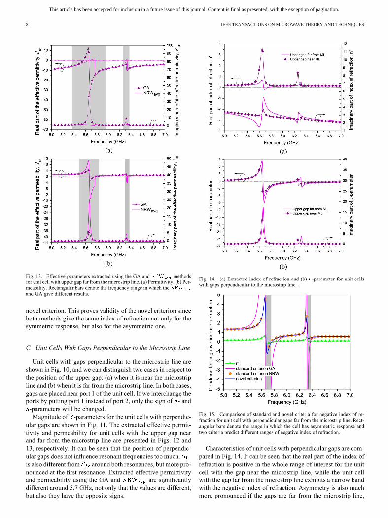
Fig. 13. Effective parameters extracted using the GA and methodsfor unit cell with upper gap far from the microstrip line. (a) Permittivity. (b) Per-meability. Rectangular bars denote the frequency range in which theand GA give different results.
novel criterion. This proves validity of the novel criterion sinceboth methods give the same index of refraction not only for thesymmetric response, but also for the asymmetric one.
C. Unit Cells With Gaps Perpendicular to the Microstrip Line
Unit cells with gaps perpendicular to the microstrip line areshown in Fig. 10, and we can distinguish two cases in respect tothe position of the upper gap: (a) when it is near the microstripline and (b) when it is far from the microstrip line. In both cases,gaps are placed near port 1 of the unit cell. If we interchange theports by putting port 1 instead of port 2, only the sign of - and-parameters will be changed.Magnitude of -parameters for the unit cells with perpendic-
ular gaps are shown in Fig. 11. The extracted effective permit-tivity and permeability for unit cells with the upper gap nearand far from the microstrip line are presented in Figs. 12 and13, respectively. It can be seen that the position of perpendic-ular gaps does not influence resonant frequencies too much.is also different from around both resonances, but more pro-nounced at the first resonance. Extracted effective permittivityand permeability using the GA and are significantlydifferent around 5.7 GHz, not only that the values are different,but also they have the opposite signs.
Fig. 14. (a) Extracted index of refraction and (b) -parameter for unit cellswith gaps perpendicular to the microstrip line.
Fig. 15. Comparison of standard and novel criteria for negative index of re-fraction for unit cell with perpendicular gaps far from the microstrip line. Rect-angular bars denote the range in which the cell has asymmetric response andtwo criteria predict different ranges of negative index of refraction.
Characteristics of unit cells with perpendicular gaps are com-pared in Fig. 14. It can be seen that the real part of the index ofrefraction is positive in the whole range of interest for the unitcell with the gap near the microstrip line, while the unit cellwith the gap far from the microstrip line exhibits a narrow bandwith the negative index of refraction. Asymmetry is also muchmore pronounced if the gaps are far from the microstrip line,
This article has been accepted for inclusion in a future issue of this journal. Content is final as presented, with the exception of pagination.
MILOSEVIC et al.: EFFECTIVE EM PARAMETERS OF METAMATERIAL TRANSMISSION LINE 9
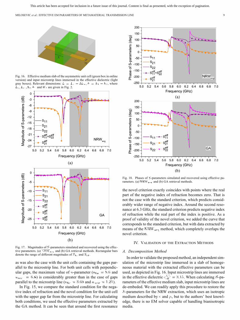
Fig. 16. Effective medium slab of the asymmetric unit cell (green box in onlineversion) and input microstrip lines immersed in the effective dielectric (lightgray boxes). Relevant dimensions: , where
and are given in Fig. 2.
Fig. 17. Magnitudes of -parameters simulated and recovered using the effec-tive parameters. (a) and (b) GA retrieval methods. Rectangular barsdenote the range of different magnitudes of and .
as was also the case with the unit cells containing the gaps par-allel to the microstrip line. For both unit cells with perpendic-ular gaps, the maximum value of -parameter ( and
) is considerably greater than in the case of gapsparallel to the microstrip line ( and ).In Fig. 15, we compare the standard condition for the nega-
tive index of refraction and the novel condition for the unit cellwith the upper gap far from the microstrip line. For calculatingboth conditions, we used the effective parameters extracted bythe GA method. It can be seen that around the first resonance
Fig. 18. Phases of -parameters simulated and recovered using effective pa-rameters. (a) and (b) GA retrieval methods.
the novel criterion exactly coincides with points where the realpart of the negative index of refraction becomes zero. That isnot the case with the standard criterion, which predicts consid-erably wider range of negative index. Around the second reso-nance at 6.3 GHz, the standard criterion predicts negative indexof refraction while the real part of the index is positive. As aproof of validity of the novel criterion, we added the curve thatcorresponds to the standard criterion, but with data extracted bymeans of the method, which completely overlaps thenovel criterion.
IV. VALIDATION OF THE EXTRACTION METHODS
A. Decomposition Method
In order to validate the proposedmethod, an independent sim-ulation of the microstrip line immersed in a slab of homoge-neous material with the extracted effective parameters can beused, as depicted in Fig. 16. Input microstrip lines are immersedin the effective dielectric . When calculating -pa-rameters of the effective medium slab, input microstrip lines arede-embeded. We can readily apply this procedure to restore the-parameters for the NRW extraction, which uses an isotropicmedium described by and , but to the authors’ best knowl-edge, there is no EM solver capable of handling bianisotropicmedia.

This article has been accepted for inclusion in a future issue of this journal. Content is final as presented, with the exception of pagination.
10 IEEE TRANSACTIONS ON MICROWAVE THEORY AND TECHNIQUES
Fig. 19. Magnitudes of -parameters simulated and recovered using the effec-tive parameters. (a) and (b) GA retrieval methods. Rectangular barsdenote the range of different magnitudes of and .
Therefore, we propose the following work-around: we simu-late two isotropic slabs corresponding to the - and -pa-rameters described above, to obtain two sets of -pa-rameters, denoted and , respectively.Now, if we observe (19) more closely, we note that it repre-sents what is known as eigendecomposition of a matrix in linearalgebra, where represents eigenvalues, and columns of ma-trix represent eigenvectors. From (17) and (19), it follows thatthe matrices , since they imply a single value ofimpedance , respectively, will decompose in the followingform:
(30)
where
(31)
respectively. Note that the eigenvalues are the same for allthree matrices.From the simulation of the slabs and , we ob-
tain two sets of -parameters, which can be converted to. We then perform the eigendecomposition of
these matrices to obtain the form of (30). This decomposition
Fig. 20. Phases of -parameters simulated and recovered using the effectiveparameters. (a) and (b) GA retrieval methods.
is readily available in software packages like MATLAB, and weonly need to arrange eigenvalues and eigenvectors in the sameorder as in (30), which can be done according to the passivitycriterion (26). Now we can obtain the matrix as
(32)
and finally, the resulting matrix according to (19).
B. Unit Cell With Gaps Parallel to the Microstrip Line
The -parameters resulting from the described approachfor the unit cell with gaps parallel and far from the microstripline [see Fig. 2(b)], compared with the original simulations,are shown on Figs. 17 and 18, for both the and GAmethod. The method [see Figs. 17(a) and 18(a)]results in symmetric response (therefore only one reflectioncoefficient is reconstructed), which clearly failsto reproduce reflection in the range of pronounced asymmetrycorrectly (marked with a rectangular bar). This is most visiblein phase, where the obtained value behaves as mean of theoriginal phases of and (this is expected because of theused averaging procedure).The GA method, however, clearly distinguishes two different
values of reflection coefficients, which are very close to the orig-inal values [see Figs. 17(b) and 18(a)]. It is clearly visible that
This article has been accepted for inclusion in a future issue of this journal. Content is final as presented, with the exception of pagination.
MILOSEVIC et al.: EFFECTIVE EM PARAMETERS OF METAMATERIAL TRANSMISSION LINE 11
the effective parameters extracted by the GA method allow therecovery of all -parameters, which is not the case with theparameters retrieved by the method, that can restoreonly , but not and in the range where asymmetry ispresent. The unit cell has symmetric response out of that rangeand both methods work correctly. We believe that the presentedresults clearly show that the GA method is advantageous overthe when asymmetry is present, while it gives exactlythe same results as the well-established NRW method for sym-metric response.
C. Unit Cell With Gaps Perpendicular to the Microstrip Line
Results for the unit cell with gaps perpendicular to, and uppergap near the microstrip line [see Fig. 10(b)], compared withthe original simulations, are shown in Figs. 19 and 20, for the
and GA methods. Again, the method [seeFigs. 19(b) and 20(b) reproduces only the mean value of re-flection, the disparity here being even more striking, due to thegreater asymmetry of the unit cell. The GA method closely re-produces both reflection coefficients once again [see Figs. 19(b)and 20(b)]. To conclude, the GA method is able to restore all-parameters in the whole frequency range of interest, whilethe method recovers them only in the range of sym-metric response. Especially good agreement is obtained in thephases of -parameters. There are small discrepancies in the re-covered magnitude of around the second resonance, whichappear equally in both methods.
V. CONCLUSION
In this paper, we have presented the GA for the extractionof effective parameters for the metamaterial transmission lineloaded with asymmetric unit cells. To describe the asymmetry,we have introduced an equivalent bianisotropic medium, whichemulates the effect of asymmetric unit cells. Besides standardconstitutive parameters such as permittivity, permeability, andcharacteristic impedance, the equivalent medium is describedby two additional parameters, and , which are very useful asa measure of asymmetry.We derived a novel condition necessary for achieving a nega-
tive index of refraction in the bianisotropic medium. Accordingto it, the criterion valid for isotropic medium is relaxed in therange in which the real and imaginary part of the -parameterare both negative or positive, while the criterion becomes morestrict if they have different signs.The proposed generalized extraction procedure and the
method, adopted for asymmetric unit cells, are ap-plied to novel dual-band unit cells. They consist of BSC SRRswith gaps displaced from the center (to the left and to theright or up and down), along two gap-bearing sides, which areplaced one above the other. It was shown that unit cells withgaps parallel with the microstrip line exhibit asymmetry onlyaround one resonance. Unit cells with gaps perpendicular tothe microstrip line have a very asymmetric response aroundboth resonances. Therefore, the effective permittivity andpermeability extracted using the GA and methods aresignificantly different.To conclude, we have shown that the procedure
gives the correct index of refraction in the whole frequency
range, but wrong effective permittivity, permeability, and char-acteristic impedance in the range of asymmetric response.This was proven through the validation procedure where the
asymmetric unit cell was replaced by effective medium slabswith the parameters extracted by the proposed GA method. Theall original -parameters were successfully restored, which wasnot the case when the parameters extracted by the approximate
method are used.
ACKNOWLEDGMENT
The authors would like to thankWIPL-D Belgrade for the useof software licenses.
REFERENCES
[1] V. G. Veselago, “Electrodynamics of substances with simultaneouslynegative and ,” Sov. Phys.–Usp., vol. 10, no. 4, pp. 509–514, 1968.
[2] J. B. Pendry, “Negative refraction makes a perfect lens,” Phys. Rev.Lett. vol. 85, pp. 3966–3969, Oct. 2000. [Online]. Available: http://link.aps.org/doi/10.1103/PhysRevLett.85.3966
[3] C. Caloz and T. Itoh, Electromagnetic Metamaterials: TransmissionLine Theory and Microwave Applications : The Engineering Ap-proach. New York, NY, USA: Wiley, 2006.
[4] L. Landau, E. Lifshits, and L. Pitaevskii, Electrodynamics of Contin-uous Media, 2nd ed. Oxford, U.K.: Pergamon, 1984.
[5] J. B. Pendry, A. J. Holden, W. J. Stewart, and I. Youngs, “Extremelylow frequency plasmons in metallic mesostructures,” Phys. Rev. Lett.vol. 76, pp. 4773–4776, Jun. 1996. [Online]. Available: http://link.aps.org/doi/10.1103/PhysRevLett.76.4773
[6] J. Pendry, A. Holden, D. Robbins, and W. Stewart, “Magnetism fromconductors and enhanced nonlinear phenomena,” IEEE Trans. Microw.Theory Techn., vol. 47, no. 11, pp. 2075–2084, Nov. 1999.
[7] A. M. Nicolson and G. F. Ross, “Measurement of the intrinsic prop-erties of materials by time-domain techniques,” IEEE Trans. Instrum.Meas., vol. IM-19, no. 4, pp. 377–382, Nov. 1970.
[8] W. Weir, “Automatic measurement of complex dielectric constant andpermeability at microwave frequencies,” Proc. IEEE, vol. 62, no. 1, pp.33–36, Jan. 1974.
[9] D. R. Smith, S. Schultz, P. Markos̆, and C. M. Soukoulis, “De-termination of effective permittivity and permeability of meta-materials from reflection and transmission coefficients,” Phys.Rev. B, Condens. Matter vol. 65, Apr. 2002. [Online]. Available:http://link.aps.org/doi/10.1103/PhysRevB.65.195104, Art. ID 195104
[10] P. Markos and C. Soukoulis, “Transmission properties and effectiveelectromagnetic parameters of double negative metamaterials,” Opt.Exp. vol. 11, no. 7, pp. 649–661, Apr. 2003. [Online]. Available: http://www.opticsexpress.org/abstract.cfm?URI=oe-11-7-649
[11] S.-G. Mao, S.-L. Chen, and C.-W. Huang, “Effective electromagneticparameters of novel distributed left-handed microstrip lines,” IEEETrans. Microw. Theory Techn., vol. 53, no. 4, pp. 1515–1521, Apr.2005.
[12] D. R. Smith, D. C. Vier, T. Koschny, and C. M. Soukoulis, “Elec-tromagnetic parameter retrieval from inhomogeneous metamaterials,”Phys. Rev. E, Stat. Phys. Plasmas Fluids Relat. Interdiscip. Top. vol. 71,Mar. 2005. [Online]. Available: http://link.aps.org/doi/10.1103/Phys-RevE.71.036617, Art. ID 036617
[13] R. Marqués, F. Medina, and R. Rafii-El-Idrissi, “Role of bianisotropyin negative permeability and left-handed metamaterials,” Phys. Rev. B,Condens. Matter vol. 65, Apr. 2002. [Online]. Available: http://link.aps.org/doi/10.1103/PhysRevB.65.144440, Art. ID 144440
[14] X. Chen, B.-I. Wu, J. A. Kong, and T. M. Grzegorczyk, “Retrieval ofthe effective constitutive parameters of bianisotropic metamaterials,”Phys. Rev. E, Stat. Phys. Plasmas Fluids Relat. Interdiscip. Top. vol. 71,pp. –, Apr. 2005. [Online]. Available: http://link.aps.org/doi/10.1103/PhysRevE.71.046610, Art. ID 046610
[15] C. Kriegler, M. Rill, S. Linden, and M. Wegener, “Bianisotropic pho-tonic metamaterials,” IEEE J. Sel. Top. Quantum Electron., vol. 16, no.2, pp. 367–375, Mar.–Apr 2010.
[16] A. Kildishev, J. Borneman, X. Ni, V. Shalaev, and V. Drachev, “Bian-isotropic effective parameters of optical metamagnetics and negative-index materials,” Proc. IEEE, vol. 19, no. 10, pp. 1691–1700, Oct.2011.

This article has been accepted for inclusion in a future issue of this journal. Content is final as presented, with the exception of pagination.
12 IEEE TRANSACTIONS ON MICROWAVE THEORY AND TECHNIQUES
[17] A. Alù, “First-principles homogenization theory for periodic metama-terials,” Phys. Rev. B, Condens. Matter vol. 84, Aug. 2011. [Online].Available: http://link.aps.org/doi/10.1103/PhysRevB.84.075153, Art.ID 075153
[18] T. Koschny, P. Markos̆, E. N. Economou, D. R. Smith, D. C. Vier, andC. M. Soukoulis, “Impact of inherent periodic structure on effectivemedium description of left-handed and related metamaterials,” Phys.Rev. B, Condens. Matter vol. 71, Jun. 2005. [Online]. Available: http://link.aps.org/doi/10.1103/PhysRevB.71.245105, Art. ID 245105
[19] A. Alù, “Restoring the physical meaning of metamaterial constitutiveparameters,” Phys. Rev. B, Condens. Matter vol. 83, Feb. 2011. [On-line]. Available: http://link.aps.org/doi/10.1103/PhysRevB.83.081102,Art. ID 081102
[20] A. Sihvola and I. V. Lindell, , F. Capolino, Ed., “Bianisotropic mate-rials and PEMC,” in Theory and Phenomena of Metamaterials. BocaRaton, FL, USA: CRC Press, 2009, pp. 26.1–26.7.
[21] M. W. McCall, A. Lakhtakia, and W. S. Weiglhofer, “The negativeindex of refraction demystified,” Eur. J. Phys. vol. 23, no. 3, pp. 353–,2002. [Online]. Available: http://stacks.iop.org/0143-0807/23/i=3/a=314
[22] A. Lakhtakia, M. W. McCall, and W. S. Weiglhofer, , W. Weiglhoferand A. Lakhtakia, Eds., “Negative phase-velocity mediums,” in Intro-duction to Complex Mediums for Optics and Electromagnetics, ser.SPIE Press Monograph. Bellingham, WA, USA: SPIE Press, 2003,pp. 347–363.
[23] D. Pozar, Microwave Engineering, 3rd ed. New York, NY, USA:Wiley, 2005.
[24] X. Chen, T. M. Grzegorczyk, B.-I. Wu, J. Pacheco, and J. A. Kong,“Robust method to retrieve the constitutive effective parameters ofmetamaterials,” Phys. Rev. E, Stat. Phys. Plasmas Fluids Relat. Inter-discip. Top. vol. 70, Jul. 2004. [Online]. Available: http://link.aps.org/doi/10.1103/PhysRevE.70.016608, Art. ID 016608
[25] Z. Szabo, G.-H. Park, R. Hedge, and E.-P. Li, “A unique extractionof metamaterial parameters based on Kramers–Kronig relationship,”IEEE Trans. Microw. Theory Techn., vol. 58, no. 10, pp. 2646–2653,Oct. 2010.
[26] N. Liu, H. Liu, S. Zhu, and H. Giessen, “Stereometamaterials,” Nat.Photon., vol. 3, pp. 157–162, Mar. 2009.
[27] R. Bojanic, B. Jokanovic, and V. Milosevic, “Multiband delay lineswith reconfigurable split-ring resonators,” in 10th Int. Telecommun. inModern Satellite Cable and Broadcast. Services Conf., 2011, vol. 1,pp. 31–34.
Vojislav Milosevic was born in Belgrade, Serbia, onApril 5, 1986. He received the Dipl. Ing. and M.Sc.degrees in electrical engineering from the Universityof Belgrade, Belgrade, Serbia, in 2009 and 2012, re-spectively, and is currently working toward the Ph.D.degree at the University of Belgrade.In 2010, he became a Research Assistant with the
Photonic Center, Institute of Physics, University ofBelgrade. His research interests include EMmetama-terials and homogenization theory.
Branka Jokanovic (M’89) received the Dipl. Ing.,M.Sc.. and Ph.D. degrees in electrical engineeringfrom the University of Belgrade, Belgrade, Serbia, in1977, 1988, and 1999, respectively.She is currently a Research Professor with the
Institute of Physics, University of Belgrade. Priorto joining the Photonic Center, Institute of Physics,she was the Head of the Microwave Department,Institute IMTEL, Belgrade, Serbia. She is a Cor-responding Member of the Serbian Academy ofEngineering Sciences. She initiated the Yugoslav
microwave theory and techniques journal Microwave Review for which shewas the editor for six years (1994–2000). Her current research interestsinclude modeling, simulation, and characterization of microwave and photonicmetamaterials for wireless communications and sensors.Dr. Jokanovic was one of the founders of the Yugoslav IEEE Microwave
Theory and Techniques Society (IEEE MTT-S) Chapter and its chairpersonfrom 1989 to 2000. She also founded the Yugoslav Association for MicrowaveTechniques and Technology in 1994. She was the recipient of the 1996 IMTELInstitute Award for Scientific Contribution, the 2000 IEEE Third MillenniumAward, and the 2005 Yugoslav IEEE MTT-S Distinguished Service Award.
Radovan Bojanic was born in Knin, Croatia, in1986. He received the Dipl.Ing. and M.Sc. degreesin electrical engineering from the University ofBelgrade, Belgrade, Serbia, in 2009 and 2012,respectively, and is currently working toward thePh.D. degree at the University of Belgrade.Since 2010, he has been with the Institute of
Physics, University of Belgrade, as Research As-sistant with the Photonic Center, where he has beeninvolved in modeling and simulation of microwavecircuits.
Copyright © 2022 FDOKUMEN