CS2060 -HIGH SPEED NETWORKS PART-A UNIT I -HIGH SPEED NETWORKS
Upload
khangminh22Category
view
0download
0
NASA Contractor Report 177578
Technology Needs for High-SpeedRotorcraftJohn Rutherford, Matthew O'Rourke, Christopher Martin, Marc Lovenguth,
and Clark Mitchell
McDonnell Douglas Helicopter Company, Mesa, Arizona
Prepared forAmes Research Center
CONTRACT NAS2-13070
April 1991
National Aeronautics andSpace Administration
Ames Research CenterMoffett Field, California 94035-1000
https://ntrs.nasa.gov/search.jsp?R=19910013823 2020-03-19T17:38:16+00:00Z


TABLE OF CONTENTS
Page
SECTION I - INITIAL TECHNOLOGY ASSESSMENT AND CONCEPT DEFINITION
SUMMARY 1-1INTRODUCTION 1-3INITIAL CONCEPT SELECTION 1-4
Initial Concept Description 1-5Results of Initial Selection 1-7
CONCEPT SIZING 1-9Generic Mission 1-9
Configuration Sizing Assumptions 1-9Weights Methodology 1-10Sizing for Optimum Cruise Altitude 1- I 1Rotor Parametric Sizing Matrices I- 12Sized Concept Descriptions 1-17Trail-Rotor Convertiplane General Description 1-17Trail-Rotor Convertiplane Conversion Description 1-18Folding Tilt Rotor General Description 1-19Folding Tilt-Rotor Conversion Description 1-20Tilt Rotor General Description 1-21Tilt Rotor Conversion Description 1-22
Rotor/Wing Description 1-23Rotor/Wing Conversion Description 1-24Tilt Wing Convertiplane General Description 1-25Tilt Wing Conversion Description 1-26Initial Technology Assessment 1-28Structures & Materials 1-28
Propulsion 1-29Drive System 1-30Aerodynamics and Acoustics 1-31Aerodynamics of High-Speed Forward Flight 1-32Prop/Rotor Performance 1- 34Conversion Axis - Center of Gravity Relationship 1-35Rotor/Wing Helicopter and Airplane Flight Requirements 1-36Dynamics and Aeroelasticity 1-38
TECHNOLOGY TRADE STUDIES 1-40Measures of Effectiveness 1-40
Current Technology Study 1-40Advanced Technology Impact 1-43
iii
G •
' _IR _J_LtlIBI_H_ _ PRECEDING PAGE BLANK NOT FILMED

TABLE O1_ CONTENTS (continued)
Advanced Technology StudyConcept Weight SummaryConclusions Drawn From Trade Studies
RECOMMENDATION OF CONCEPTS FOR TASK 2
Concept RankingSelection for Task 2
1-481-501-52!-541-551-55
SECTION lI - TECHNOLOGY EVALUATION FOR SELECTED CONCE_S
INTRODUCTIONCONCEPT SIZING
Design CriteriaAssumptions
SizingAircraft DescriptionConversionPerformance
Tilt Wing Subsystem DesignRotor/Wing Subsystem Design
SENSITIVITY STUDIES
Mission/Design SensitivitiesTechnology SensitivitiesIdentification of Critical Technologies
2-12-22-22-42-72-142-172-202-322-352-392-392-452-59
SECTION Ill - ENABLING TECItNOLOGY PLAN
TECHNOLOGY DEVELOPMENT NEEDSIntroduction
AerodynamicsPropulsionDrive SystemsStructures
Stability and ControlControl SystemsDynamicsSummary
3-I3-I3-13-43-63-103-123-153-163-20
SECTION IV - REFERENCES
REFERENCES 4-1
APPENDIX A-i
iv

LIST OF FIGURES
Section I
Figure
1-1
1-21-31-41-51-61-71-81-91-101-111-121-131-141-151-161-171-181-191-201-211-221-231-241-251-261-271-281-291-301-311-321-331-341-351-361-371-381-39
Sixteen Configurations Proposed by Ten PersonMulti-Disciplinary GroupConcept Evaluation MatrixFive Concepts Selected for Task 1 Evaluation Generic MissionGeneric Mission
Optimum Cruise Altitude Determination Folding Tilt RotorTurbofan Trail Rotor - Parametric Design Matrix
Folding Tilt Rotor - Parametric Design MatrixPropfan Trail Rotor - Parametric Design MatrixTilt Rotor - Parametric Design Matrix
Tilt Wing - Parametric Design MatrixRotor/Wing Sizing - Parametric Design MatrixTrail Rotor Convertiplane Final ConfigurationTrail Rotor Conversion SequenceFolding Tilt Rotor Final ConfigurationFolding Tilt Rotor Conversion SequenceTilt Rotor Final ConfigurationTilt Rotor Conversion SequenceRotor Wing Final ConfigurationRotor/Wing Conversion SequenceTilt Wing Final ConfigurationTilt Wing Conversion SequenceJTAGG SFC and SHP/WT Goals (T700 Baseline)
Drive Train Weight TrendsHigh-Speed Airframe AerodynamicsMDD Boundaries of High-Speed Rotorcraft Wing AirfoilsProp/Rotor Cruise PerformanceConversion Axis - Center of Gravity RelationshipConflicting Helicopter and Airplane Flight RequirementsMeasures of Effectiveness - Current Technology
Performance Indices - Current TechnologyEffect of Reduced SFC
Effect of Reduced Engine WeightEffect of Reduced Drive System WeightEffect of Improved AerodynamicsEffect of Reduced Structure WeightMeasures of Effectiveness - Advanced TechnologyPerformance Indices - Advanced TechnologyConcepts Weights SummaryConcept Selection Matrix for Task 2
Page
1-51-61-81-91-111-131-131-141-141-161-161-171-I81-191-201-211-221-231-241-261-271-291-301-321-331-341-351-371-411-421-431-441-451-461-471-481-501-511-54

LIST OF FIGURES (continued)
Section II
2-12-22-32-42-52-62-7
2-82-92-102-1I2-122-132-14
2-152-162-172-182-192-202-212-222-232-242-252-262-272-282-292-302-312-322-332-342-352-362-372-382-392-40
Tilt Wing Parametric Sizing Matrix 2-8Rotor/Wing Parametric Sizing Matrix 2-10Tilt Wing Military Transport 2-14
Rotor/Wing Ground Attack Aircraft 2-16Velocity Diagram Describing Tilt Wing Conversion 2-17XC- 142 Reconversion Time History 2-19Wind Tunnel Test Showing Rotor/Wing Conversion From Helicopterto Airplane Mode 2-20Tilt Wing Flight Envelope 2-21Rotor/Wing Flight Envelope 2-21Tilt Wing Power Required - All Modes 2-22Rotor/Wing Power Required - All Modes 2-22Tilt Wing Nondimensional Hover Rotor Power Required 2-23Tilt Wing Hover Ceiling 2-24Tilt Wing STOL Performance - Wing at 60 Deg Incidence 2-24Tilt Wing L/D - Airplane Mode 2-26Tilt Wing - Rotor Cruise Performance 2-26Tilt Wing Specific Range 2-27Tilt Wing Payload - Range Diagram 2-27Rotor/wing Nondimensional Rotor Hover Power Required 2-28Rotor/wing Hover Ceiling 2-28Rotor/Wing L/D - Autogyro Mode 2-29Rotor/Wing L/D - Airplane Mode 2-30Rotor/Wing Specific Range 2-31Rotor/Wing Payload - Range Diagram 2-31Tilt Wing Hub With Controls 2-32Tilt Wing Drive System 2-33Two-Speed Gearbox 2-34Rotor/Wing Hub With Controls 2-35Rotor/Wing Propulsion System Ducting 2-36Rotor/wing Tip Jet 2-37Rotor/Wing Locking-Stopping Mechanism 2-38Sensitivity to Changes in Mission Hover Time 2-40Sensitivity to Changes in Lift-to-Drag Ratio 2-40
2-41SensitivitySensitivitySensitivitySensitivitySensitivitySensitivityTilt Wing:
to Changes in Cruise Speedto Changes in Average Rotor Lift Coefficientto Changes in Conversion Wing Areato Changes in Specific Fuel Consumptionto Changes in Engine Power-to-Weight Ratioto a 5 dB Sideline Noise ReductionEffect of a General Weight Reduction
2-422-422-432-442-442-48
vi

LIST OF FIGURES (continued)
2-41
2-422-43
2-44
2-452-46
2-472-482-492-502-512-52
2-532-54
2-55
Tilt Wing: Effect of a Reduction Wing Thickness With no Change inWeight 2-48Tilt Wing: Effect of a 35.5% Reduction in SFC 2-49Tilt Wing: Effect of a 100% Increase in Engine Power-to-WeightRatio 2-50
Tilt Wing: Effect of an Increase in Cruise Efficiency (rlc,) 2-50
Example of an Advanced Coaxial Prop/Rotor 2-51Tilt Wing: Effect of a 20% Reduction in Gear Box Weight and 25% inDrive Shaft Weight 2-52
Tilt Wing: Effect of Increasing Wing Airfoil MDD TO 0.75 2-52Tilt Wing: Effect of Increasing Conversion Wing Loading to 120 PSF 2-53Effect of Reducing Empennage Size 15% 2-54Rotor/Wing: Effect of a General Weight Reduction 2-55Rotor/Wing: Effect of a 30% Reduction in SFC 2-55Rotor/Wing: Effect of a 120% Increase in Engine Thrust-to-WeightRatio. 2-56
Rotor/Wing: Effect of a 12.3% Reduction in Cruise Wing Drag 2-57Rotor/Wing: Effect of Increasing Conversion Wing Loading to 90PSF 2-58
Rotor/Wing: Effect of a 15% Reduction in Empennage Size 2-58
Section HI
3-13-23-33-43-53-63-73-83-93-103-113-12
Aerodynamics Technology Development Timelines: Tilt WingAerodynamics Technology Development Timelines: Rotor/WingIHPTET Timeline
Rotor/Wing Diverter ValveDrive Systems Technology Development Timelines: Tilt WingDrive Systems Technology Development Timelines: Rotor/WingStructures Technology Development Timelines
3-23-43-53-73-83-93-12
Stability and Control Technology Development Timeline: Tilt Wing 3-13Stability and Control Technology Development Timeline: Rotor/Wing 3-14Control Systems Technology Development Timelines 3-16Dynamics Technology Development Timelines - Tilt Wing 3-18Dynamics Technology Development Timelines - Rotor/Wing 3-20
vii

LIST OF TABLES
Section II
Table
2-12-22-32-42-52-62-72-82-92-102-112-122-132-142-15
Page
Mission Weight Requirements 2-3Current Technology Tilt Wing Design Parameters 2-9Current Technology Rotor/Wing Design Parameters 2-11Tilt Wing Weight Breakdown 2-12Rotor/Wing Weight Breakdown 2-13Concept Weights and Inertias 2-14Tilt Wing Drag Breakdown - Airplane Mode 2-25Rotor/Wing Drag Breakdown - Airplane Mode 2-30Achievable Technology Matrix 2-46Current Technology Measures of Effectiveness 2-47Increases in Measures of Effectiveness due to Advanced Technology 2-60Advanced Technology Tilt Wing Design Parameters 2-60Advanced Technology Rotor/Wing Design Parameters 2-61Advanced Tilt Wing Weight Breakdown 2-61Advanced Rotor/Wing Weight Breakdown 2-62
Section III
Tilt Wing Technology Assessment MatrixRotor/Wing Technology Assessment MatrixCommon Technology Assessment Matrix
3-13-23-3
3-223-223-23
viii

SECTION I
INI'FIAL TECIINOLOGY ASSESSMENT AND CONCEPT DEFINITION

SUMMARY
This study consists of three main tasks: Initial Technology Assessment and Concept Definition,Technology Evaluation for Selected Concepts, and the Enabling Technology Plan. The overall
goal of the study is to identify the technology requirements of high-speed rotorcraft (> 350KTAS) which maintain helicopter-like hover efficiencies. To achieve the study goal, sizing theconcept represents a secondary priority. Of more importance, is the ability to performtechnology sensitivity studies for selected concepts.
During the first task, five concepts were evaluated based on specified measures of effectiveness.These concepts included the Tilt Wing, Tilt Rotor, Rotor/Wing, Folding Tilt Rotor and TrailRotor. The latter was evaluated in two configurations: a turbofan convertible engine version
and a propfan version. The results of the evaluation demonstrated that the concepts employingintegrated lift or propulsion systems, such as the Tilt Wing, Tilt Rotor and Rotor/Wing, exceededthe effectiveness of the other concepts employing dual systems, such as the folding rotor
concepts. The extra weight and drag of the folding rotor systems significantly contributed totheir poor performance.
An initial technology assessment demonstrated the dramatic impact of IHPTET goals on all theconcepts, leading to the preliminary conclusion that improvement in propulsion is perhaps thesingle most important technology across all concepts. The propulsive efficiency of theprop/rotor concepts requires some means to reduce tip speed in cruise if they are to achieve 450KTAS. The required tip speed reduction is about 50% from hover. Improvements in rotoraerodynamics are aimed toward cruise efficiency, over hover power requirements for thesevehicles. Another important result indicates that the drive systems for these high-speed vehiclescontribute immensely to their empty weight. Since cruise typically sizes the vehicles, themaximum power requirements occur in this regime while tip sp.eed requirements decrease bynearly 50%. The increased torque in this flight mode severely _mpacts the drive system weight.This tends to make prop/rotor vehicles sensitive to anything which increases cruise power due to
the cascading effect throughout the system.
The Rotor/Wing benefits from possessing an integrated lift system and by not possessing a drivesystem (it is reaction driven). Its "Achilles Heel" is the inefficiency of power transmission (onlyabout 50%) and the requirement to use less than optimum efficiency, low by-pass ratio turbofanengines. The combination of poor fuel economy and less than desired wing loading increases thefuel requirements and the gross weight of the vehicle. However, the empty weight remains lowindicating the probability of reduced maintenance and acquisition costs. Like the other concepts,its lack of development assures risk, but for the purposes of the study, since identification ofneeded technology is the goal, risk is down played.
Concepts selected for the second task included the Tilt Wing, in the military transport mission,and the Rotor/Wing, in the ground attack role. Extensive sizing and performance wereaccomplished on these concepts during this task, results of which may be found in the Appendix.Closer focus on the conversion of Tilt Wing demonstrated a clear relationship between wingloading, disk loading and high-lift devices used on the wing. An effort to increase conversionwing loading of the Rotor/Wing resulted in the ability to convert in a more benign manner, whilereducing the disk loading of the vehicle. Sensitivity studies confirmed technology impacts ofTask 1. Again, propulsion technology leads in improvement potential. Another area forimprovement in Tilt Wing technology occurs due to an increase in conversion wing loading.This concept's characteristic large wing may be reduced by increasing its stall angle, by
1-1

increasingits CLmu, by increasing drag, or a combination of all. Reducing the wing size, while
maintaining nominal conversion characteristics, significantly reduces cruise drag and weight.One means to achieve high lift is the application of circulation control.
The results of Task 3 highlight time lines and suggest institutions, such as industry, governmentand universities best suited to specific technology development. The development of technologybegins with analytical methodology development and proceeds through testing/validation andsubsystem flight demonstration. Finally, the technologies for each concept are rated according torisk and payoff and prioritized. Critical technologies are identified as hose that withoutdevelopment would prohibit flight in one of the flight regimes.
Recommended high-payoff areas for investigation include:
Tilt Wing-
Feasibility study of a high-lift wingFeasibility study of prop/rotor RPM reduction schemesPreliminary design/test of a 450 knot prop/rotor
Rotor�Wing-
Assess dynamics of stopping a two-bladed rotor/wingConfiguration wind tunnel testingAssess concept feasibility and vehicle dynamics during conversion usinga radio controlled model
Continuing the IHPTET Program.
The authors would like to acknowledge the significant contribution to the final reportmade by many individuals. They are: Andrew Elliott, John Fish, Robert Fitzpatrick, Don Kunz,Derek LeThanh, Lawson Robinson, and Brian Smith. Their time and effort is greatly
appreciated.
1-2

INTRODUCTION
Development of an air vehicle capable of helicopter efficiency and jet-transport-like cruisespeeds depends on the synergistic combination of advanced technologies into a configurationadapted to a specified mission. The U. S. Patent Office issued patents for high-speed rotorcraftas early as the late 1920's 1. Several concepts flew as technology or feasibility demonstrators,with varying degrees of success, in the late 1950's and early 1960's. Recently, the XV-15, andthe V-22 tilt-rotor aircraft represent the most practical attempts at the goal of hover andhigh-speed flight, but they cannot achieve the high-speed cruise desired for this study. Theincreased speed range dictates the need to examine different concepts and technologies, toinclude those which have previously been proposed.
1-3

INITIAL CONCEPT SELECTION
The selection process for Task 1 concepts included a brainstorming session attended by a tenmember, multi-disciplinary team. This team submitted sixteen concepts (Figure 1), some withmultiple configurations for consideration. These concepts included, from left to right:
Tilt WingTilt Rotor
Trail-Rotor ConvertiplaneFolding Tilt RotorAft Rotor/WingTail Sitter Rotor/WingVariable Geometry Rotor/WingStopped Rotor/wingRotor-in-WingComposite AircraftPancake Engine AircraftRotating AirfoilRotating WingVTOL Wing LifterTube FanActuator Disk
Prior to evaluation, the proposer explained the concept to the group to ensure understanding ofthe concept. This led to further discussions and in some cases, modifications of proposedconcepts. At this point, only comments regarding understanding of the concepts were allowed,to ensure free flow of ideas.
Each concept received an evaluation of good (3), fair (2), or poor (1) rating in nine areas. Thisevaluation did not include formal analysis due to time limitations, but drew on the expertisewithin the group to conceptually evaluate the concepts. The nine areas for evaluation included:
PropulsionStability and ControlStructuresConversion
Hover Efficiency (Disk Loading < 50)High-Speed Potential (Cruise 350-500 Kts)Design ComplexityMultimission CapabilityCTOL/VTOL Capability
1-4

5.
9.
I. TILT WING
AFT ROTOR]WING
ROTORS IN WING
13. ROTATING WING
2. TILT ROTOR
3. TRAIL ROTOR
CONVERTIPLANE
FOLDING__TILT ROTOR[
6. TAIL SITTERROTOR WING
x10.COMPOSITE AIRCR_T
14. VTOL WING LIFTER
7. VARIABLE GEOMETRY
ROTOR WING.
I I. PANCAKE ENGINE
15. TUBE FAN
[8. STOPPED ROTOR WING
12. ROTATING AIRFOIL
16. ACTUATOR DISK
FIGURE 1-1. SIXTEEN CONFIGURATIONS PROPOSED BY TEN PERSONMULTI-DISCIPLINARY GROUP
Initial Concept Description
The matrix, in Figure 1-2, depicts the results of the concept evaluation. Some comments on eachconfiguration follows:
Tilt Wing- Limited descent capability in conversion. High-speed limitation is based onprop/rotor for propulsion. Hover efficiency is determined by prop/rotor diameter.
Tilt Rotor- High-seed cruise potential is limited by rotor efficiency in cruise.
Trail-Rotor Convertiplane/Folding Tilt Rotor- Conversion may pose technologicalproblems. Folding rotors require a more complex hub.
Aft Rotor�Wing- Stability and control during conversion poses major problems due tolarge C.G. shift and center of lift as the wing moves aft to the fixed wing configuration. Also,maintaining lg flight could be difficult. The large hinge structure and seals required for thereaction drive system leads to concerns about the structure and complexity of the system.
Tail-Sitter Rotor�Wing- Conversion received a poor rating due to experiences with thistype of VTOL aircraft during the '60s. It lacks a CTOL capability and muhimission flexibility.
Stopped Rotor�Wing- Conversion dynamics were considered somewhat risky based onwork accomplished in the mid '60s.
1-5

Rotor-in-Wing- This concept suffered due to the incompatibility of low disk loading rotors
and desired high wing loading for cruise. It presents a difficult structural problem as well. Wings
would typically be thick, which would hurt the high-speed cruise capability.
CONCEPT
CATEGORY
PROPULSION
STRUCTURESDESIGNCOMPLEXITY
STABILITY &CONTROL
CONVERSION
HOVEREFFICIENCY
HIGH-SPEEDPOTENTIAL
CTOL/VTOL CAP
MULTIMISSIONCAP
TOTAL
TILTWING
I
2
2
2
24
TILTROTOR
2
3
26
TRC/FIR
3
2
24
AFTR/W
5
22
T-SITR/W
6
21
STOPR/W
8
24
ROTOR-IN-WING
9
21
CONCEPT
CATEGORY
PROPULSION
COMPAIC
PANCAKE,_GINE
ROTATINGAIRFOIL
ROTATINGWING
STRUCTURES 3 3 1 2
DESIGN 3 2 2 2COMPLEXITY
3 I 1 2STABILITY &CONTROL
VTOLLIFTER
HOVEREFFICIENCY
TUBEFAN
ACTUATORDISK
2 2
2 1
1 1
3
3
2
3
1
2
3
3
21
CONVERSION 2 3 3 2 2 2
3 1 1 3 1 2
HIGH-SPEEDPOTENTIAL
CTOL/VTOL CAP 1 3 3 3 3 1
MULTIMISSION 1 1 2 1 3 1CAP
TOTAL 22 18 19 21 20 15
SCORE: GOOD(3), FAIR(2), POOR(l)
FIGURE 1-2. CONCEPT EVALUATION MATRIX
1-6

Composite Aircraft- Conceptually, this concept appears to meet all the requirements withrelatively little risk. However, it requires two air vehicles which was deemed a violation of the
requirements.Pancake Engine Aircraft- The propulsion system received a poor rating due to untried
technology and potential high disk loading. No definition of low-speed control was provided.
Rotating Airfoil- This concept produces lift through the rotation of the wing in a mannersimilar to a ferris wheel. This concept is analogous to a cyclocrane. Complexity, control duringconversion and structural implication of the concept led to poor ratings.
Rotating Wing- A concept similar to the stopped rotor/wing, its wing rotates around acircular fuselage, which creates the required lift in conversion. The complexity and limitedvolume caused this to receive a low rating. It may be suitable for a ground attack vehicle,requiring volume only for a pilot. Stability and control concerns probably make this conceptunviable.
VTOL Wing Lifter- This achieves hover through engine exhaust gases blown tangentiallyover the wing to reduce upper surface pressure. The concept, as presented, had no aerodynamicmerit. Even with modifications, stability and control in hover, low wing loading in cruise andpower required to hover resulted in a poor rating.
Tube Fan- Large cylindrical fans accelerate air downward providing required thrust forlift. This resulted in high disk loading and questionable efficiency. The structure becomes morecomplex due to embedding the large fans near the wing root.
Actuator Disk- A rotating disk with guide vanes feed air, through centrifugal pumping,into a series of counter rotating blades rotating on the outside of the craft. Stability and control isquestionable at low speed. The concept would be mechanically and structurally complex if itcould work.
Results of Initial Selection
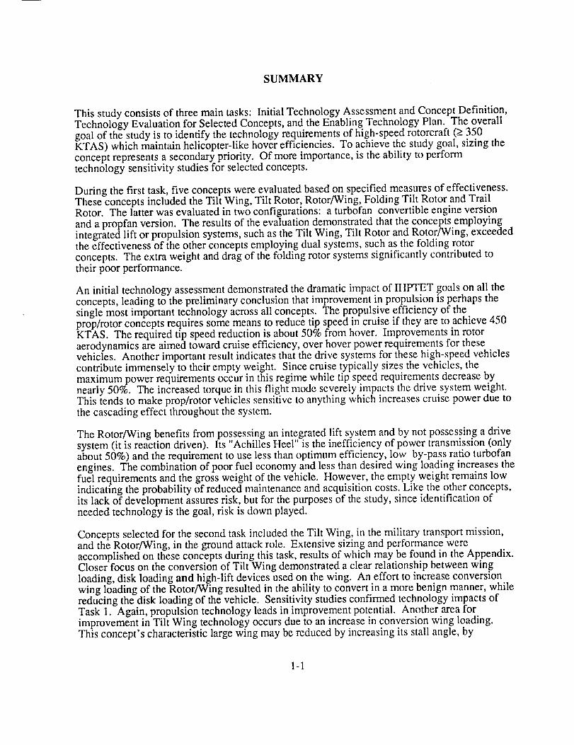
The selection of five concepts for further study in Task 1 provided the opportunity to look at thebest candidates in greater detail. It also ensured that none of the most promising concepts wereprematurely eliminated, especially since only a conceptual, subjective evaluation was initiallyperformed. The selected concepts, shown in Figure 1-3, attained the highest total ratings andinclude:
Trail-Rotor Convertiplane (TRC)Folding Tilt Rotor (FTR)Tilt Rotor
Rotor/WingTilt Wing
1-7
TILT WING TILT ROTOR ROTOR/WING
J
TRAIL ROTOR CONVERTIPLANE(PROPFAN AND TURBOFAN) FOLDING TILT ROTOR
FIGURE 1-3. FIVE CONCEPTS SELECTED FOR TASK 1 EVALUATION
One variation to the Trail Rotor study included assessment of a turbofan versus a propfan forcruise.
1-8

CONCEPT SIZING
Generic Mission
A comparative study of the selected concepts must include development of a set of requirementswhich provide a basis for sizing, while providing a common standard of performance. Thegeneric mission depicted in Figure 1-4 serves this purpose. The mission closely parallels theTask 2 missions in general. The profile consists of a taxi, hover, vertical take off segment of 10rain., followed by a climb to best cruise altitude. Once at altitude, the aircraft completes a 600nautical mile mission at 450 KTAS. The final leg consists of descent and a 10 minute verticallanding, hover, and taxi. The aircraft carry an unspecified 4500 pound payload whichcompromises between the Task 2 mission payloads, while the box size represents a moreconfiguration demanding alternative. Arguably, it eliminates a small compact attackconfiguration, but the cargo/passenger box may pose layout concerns for some concepts. Thecruise speed requires some wing sweep to achieve efficient cruise altitudes and represents asignificant increase over current high-speed rotorcraft.
BEST CRUISE ALTITUDE
450 KTAS
600 N M
VTOL VTOL
SEA LEVEL ISA SEA LEVEL ISA
4500 LB. PAYLOAD
Configuration Sizing Assumptions
The limited scope of Task 1 results in a number of assumptions utilized in the configurationsizing. The majority of the assumptions are design parameters chosen to remain constant duringthe Task 1 sizing exercises, either to simplify aircraft sizing or because determining the actualparameters requires analyses beyond the scope of Task 1. In the more intensive Task 2, theseassumptions will be verified and optimized during the final sizing of the remaining concepts.
1-9

To accountfor high-speedaeroelasticitycharacteristics,wing bending,torsionalstiffnessandwing structuralintegrity,thewing aspectratio is limited to 0 times the cosine of the wing sweepangle. This criteria represents a reasonable limit based on existing V/STOL aircraft.
Assuming a minimum wing thickness ratio of 0.18 ensures wing stiffness in helicopter flight andtorsional stiffness required for airplane mode and conversion. This assumes improvement mstructural wing design compared to the V-22 and the XV-15 with no weight penalty.
In the absence of a complete stability and control analysis, the tail surfaces are sized by XV-15tail volume coefficients. For the Folding Tilt Rotor, a canard configuration, the Beech Starshiptail volume coefficients size the control surfaces.
Based on V-22 rotor performance, the maximum blade loading (CT/o) is 0.18. By providing fora 35% maneuver margin in helicopter flight, the design hover blade loading becomes 0.1333.
The wing download in hover, based on V-22 results, is held constant at 12% hover weight for theTilt Rotor, Trail Rotor, and Folding Tilt Rotor 2. The Tilt Wing configuration eliminates wing
download. The download used for Rotor/Wing is 5%.
The rotor hover tip-speed is 750 fps for acoustic reasons. In Task 2, this parameter will beoptimized for the final concepts.
Excessive wing sweep angles result in a large difference between the locations of the hover andcruise center of lift, which may result in unique longitudinal stability problems. To minimizethese problems, the maximum allowable wing sweep angle is restricted to 20 °. This limitationinfluences the optimum cruise altitude for each concept. Further illumination of potentialstability problems associated with high sweep angles is presented on page 1-35.
Rotor clearance determines the wing span for all applicable concepts. This method of sizing
results in configuration constraints at lower disk loading due to aspect ratio limitations.
A modified version of VASCOMPII was utilized to size all Task 1 concepts but the Rotor/Wing.
Because of its unique sizing criteria, the Rotor/wing was sized by a separate code based onmethodology found in references (3,4). Both sizing codes incorporated similar weight estimating
equations and mission analysis subroutines.
Weights Methodology
The baseline weight estimation methodology used for the HSR study is documented in theMDHC Weight Estimation Handbook Series. These equations were derived using a wide rangeof helicopters, from the light scouts to the heavy lift tandem rotors, and a wide range of grossweights from 3,000 lbs to 130,000 lbs.
Starting with this methodology, modifications were made to properly sensitize the equations toV/STOL configurations, particularly tilt rotors. This was accomplished by adjusting andcalibrating the equations initially to the V-22 Osprey. This calibration results in a baseline whichhas the weight penalties associated with the V-22 design built in such as very stiff wing panels.
The difference between Task 1 concepts and the V-22 were identified and the appropriate weight
adjustments made. As an example, some concepts required an additional weight penalty due tothe requirement for a pressurized fuselage,
1-10
Common weight estimation methodology was maintained for all groups where the type of airvehicle had little effect on weight equation form (i.e., body group). As a result, it was possible touse common weight equations for all configurations except the Rotor/Wing's flight controls andwing group where configuration specific weight methods were used.
The weights of the payload, fixed equipment, avionics, and operating items were detailed fromthe Task 2 missions. As previously stated, a 4500 lb. Payload was selected. The remainingitems and their weights are: fixed equipment, 4000 lbs.; avionics, 800 lbs.; operating items, 625lbs.
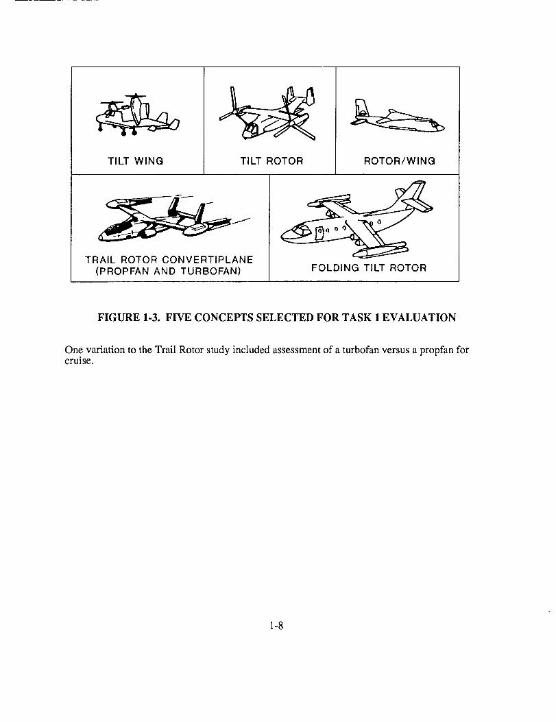
Advanced Technology Assumptions- The estimated weight savings due to advancedtechnology in the year 2010 assumes various advances which are detailed in the initialtechnology assessment portion of this report (pg 1-28). These advances result in a 25% decreasein the drive system weight, a 15% decrease in the primary structure weights, a 36% decrease inengine weight, and a 10% decrease in the secondary structure and landing gear weights.
Sizing for Optimum Cruise Altitude
75
t-_
0 70-00
t-.__
_ 65-
9
•-_ 60-O3
a
___.____1_--o W/S --- 100 psf
°"°_.__ ..- o w/sW/S==120110psf
Design Optimum "'--_ ..--'" ^_o---_j,,_- ,''_psf
W/S ----130 psfAltitude_ _---o._o------_ _,_+
....
5510000 110_00
I ' I ' I I ' I ' I ' I _ 1 ' 1 ' I ' I
12000 13000 14000 15000 16000 17000 18000 19000 20000 21000 22000 23000
Cruise Altitude, (ft)
FIGURE 1-5. OPTIMUM CRUISE ALTITUDE DETERMINATION - FOLDINGTILT ROTOR
Each configuration was sized to the altitude that yields the minimum gross weight for the designwing loading. Since hover disk loading does not influence this altitude directly, a nominal value
1-11

is fixed for this trade. Figure 1-5 represents an example showing the optimum cruise altitudesizing plot for the Folding Tilt Rotor. The locus of minimum weight for each wing loadingindicates the optimum cruising altitude as a function of wing loading.
For a given wing loading, the altitude for minimum gross weight is a function of the aircraft dragand engine characteristics. For altitudes greater than the minimum weight altitude, thecompressibility drag rises because the Mach number and aircraft lift coefficient continue toincrease, resulting in a higher gross weight. For altitudes less than the minimum, the aircraft
drag increases as the local dynamic pressure increases, resulting in more required thrust, morefuel and higher gross weight. Thus, the optimum altitude represents the point where thecompressibility drag begins to rise faster than the dynamic pressure decreases, minimizing thecruise drag and engine size of this altitude.
A significant reduction in the cruise altitude occurs as the wing loading increases. Thischaracteristic results from the drag divergence characteristics of the 18% thick wing section.The requirement for a thick wing with a small sweep introduces stringent drag divergenceboundaries that forces the optimum altitude down. Clearly, high-speed rotorcraft require thickairfoils with improved drag divergence characteristics, or wings with increased sweep, or thinnerwings for efficient cruise.
Since the optimum altitude is a function of wing loading, choosing the optimum altitudebecomes an iterative step in sizing each concept. Only one iteration determines the cruisealtitude for each concept, which is then fixed for the remainder of the sizing process. The lowestdesign gross weight solution leads to higher wing loadings. However, high wing loadings canresult in buffeting at high speeds, reduced conversion corridor and excessively high aspect ratiosat low disk loadings. For these reasons, a value of 120 psf represents the maximum allowablewing loading. Using this constraint, the example Folding Tilt Rotor's optimum altitude becomes14,000 ft.
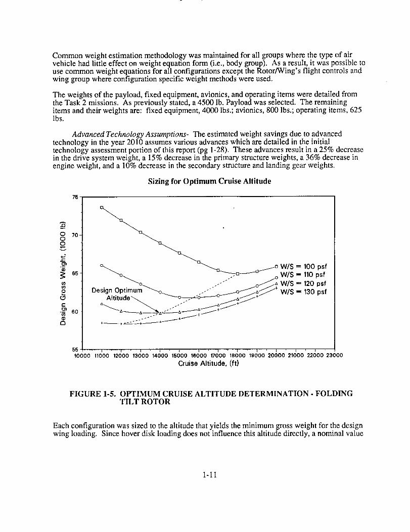
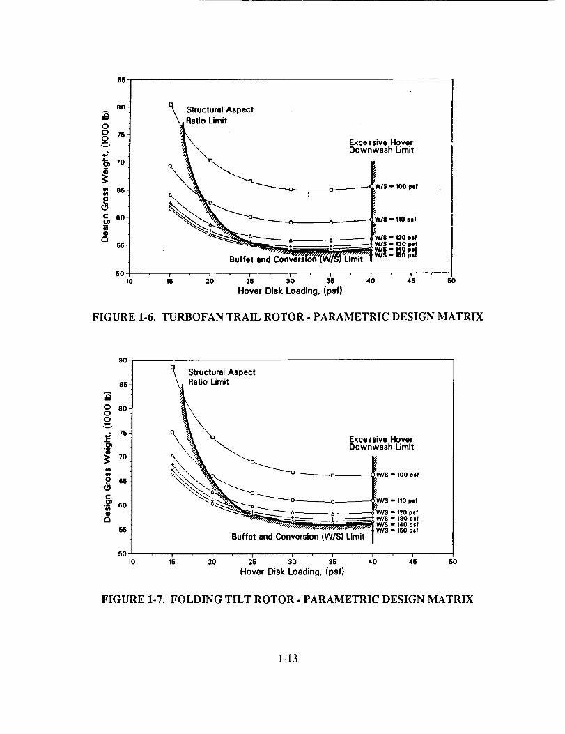
Rotor Parametric Sizing Matrices
For each case, the optimum altitude was determined for a nominal wing loading. Thisaltitude became the concept's design cruise altitude, accounting for compressibility effects andprop cruise efficiency, within the assumptions made. With this parameter fixed for each concept,sweeps varying disk loading and wing loading further defined concept gross weight (Figures 1-6thru 1-9). Adding constraints to the plots reduced the available design solutions and sometimesprohibited the minimum gross weight solution. Typical constraints placed on the solutionsincluded a maximum allowable aspect ratio, as previously defined, and a maximum wing loadingconstraint above which high-speed buffet occurs due to shock induced separation, or conversionstall speed exceeded that required for conversion. In some instances, the maximum wing loadingshown results in the locus of minimum gross weight solutions, within the cross-hatchedboundaries (as in Figure 1-8) and becomes the choice wing loading.
Rotor constraints, in the form of maximum disk loading, occur based on the maximumoverturning moments for personnel operating in the vicinity of the aircraft while it hovers inground effect. For a twin rotor system that maximum is 40 psf 5.
1-12
86
80-A,D
O
0 76-0___
.4=O) 70-"B
_ 66
0
0c 60
,mW@
056
u_ Structural AspectRatio Limit
0
.It
_n"'(W/_) Limlt
Excessive HoverDownwssh Limit
Iris - 100 per
N/8 m !10 pzf
_//S " 120 psf
WIS = 130 pzf
WIS =, 140 per
W/S = 160 pef
5O,o ,;5 =_ ='5 3;) ;5 ,'o ;5 50
Hover Disk Loading, (psf)
FIGURE 1-6. TURBOFAN TRAIL ROTOR - PARAMETRIC DESIGN MATRIX
9O
85.
0 80-00
4-_ 75"t-O)
,w4)
70-
m
o 65-c_c•-_ 5o-(/)o
a
55-
StructuralAspect
it
°xx_#, "xux. ExcessiveHover_ _ Downwash Limit
<> _o W/S -- 100 plf
/S -- 110 p|f
"__+_.+_*_ w/s - 13o pef..... "" • _ W/S-140psl
_'Li_i;l w,s- ,.o- ,
50,o 1[ =_ ='5 3'0 3'5 ,'o ,'5 50
Hover Disk Loading, (psf)
FIGURE 1-7. FOLDING TILT ROTOR - PARAMETRIC DESIGN MATRIX
1-13

85
80-A
&O0 76-0
70-.$
m 66-U)
o
12156-
Structural Aspect
atio LimitExcessive Hover
Downwssh_. Limit
_C]_O_______-------O W/$ -- 100 psi
_0-_-----0 IS - 110 psf
• ___ __.-_.--------_ W/S - 120 psf
"/ / | W/S - 130 pit
Minimum Gross Weight (W/S) I
50 ,,o ,6 =_ 2'6 30 3'5 ,'o ,'_ 5oHover Disk Loading, (psf)
FIGURE 1-8. PROPFAN TRAIL ROTOR - PARAMETRIC DESIGN MATRIX
8O
75A
O
0 700
4.Jt-
65
_ 50m0
c 55
m
5O
45
10
Structural Aspect
tio Limit
Minimum Gross Weight (W/S)
1_ ='o ,'o
Excessive HoverDownwash Limit
NIS - 100 p=f
V/S - 1tO psf
VlS - 120 psf
/VIS - 130 psi: W/S - 140 psf
='5 3_ 3'5 4'5Hover Disk Loading, (psf)
5O
FIGURE 1-9. TILT ROTOR - PARAMETRIC DESIGN MATRIX
1-14

Increasing the disk loading results in a lower aspect ratio wing for a constant wing loadingwhich, in turn, results in a lower weight wing. This ultimately reduces the overall structuralweight. Since cruise power and not hover power requirements size the concepts, the design isdriven to higher disk loadings. The high-speed requirements ap.pear to push the optimizedsolutions to higher disk loadings because the cruise power reqmrements are more stringent thanfor hover. Range may also play a role with aspect ratio determining fuel weight. A long rangemission may require higher aspect ratios wings which could drive the solution to a lower diskloading.
The trend of reduced gross weight with increasing wing. loading occurs due to reduction in wingsize (constant disk loading fixes span). This trend continues until the wing is so small that aweight and induced drag penalty cause the gross weight to increase. These trends are common toall concepts with tip mounted rotors.
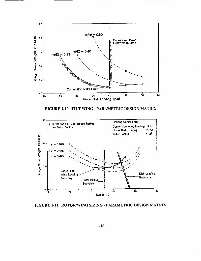
Figure 1-10 depicts the sizing trends for the Tilt Wing concept. For a given disk loading, a largerchord to diameter (c/D) ratio results in a higher gross weight design. This occurs due toincreased wing area which increases wing weight and drag, thus increasing fuel weight.
The minimum ratio attainable depends on the desired conversion characteristics of the aircraft.Unfortunately, better conversion characteristics result from aircraft with high c/D ratios.Reference 1 indicates .33 as a possible minimum value of c/D, with the use of flaps and leadingedge slats. This value was chosen as the limiting value.
For a constant value of c/D, increasing disk loading reduces gross weight, again due to the effectof wing size. Having assumed that the rotor radius defines the wing span, the chord and the spandecreased with increasing disk loading, making the wing smaller. Since cruise requirementsagain size the engines, no weight benefits occur by minimizing hover power using a very lowdisk loading.
A maximum disk loading constraint of 40 psf is imposed for the same considerations aspreviously noted.
Figure 1-11 shows the relation of the Rotor/Wing sizing parameters. One of the key design
parameters for this concept is the ratio of center-body radius to rotor radius, _. As this ratioincreases the lifting ability of the rotor system decreases, requiring more power with largerengines. This results in increasing gross weight. The relative power transmission inefficiency ofthe reaction drive system and the OEI hover requirements size the engines for this concept.Therefore, one would like to minimize the center-body, except that some minimum area isrequired for conversion. The maximum conversion wing loading, based on the conversion speedof 170 KTAS and an attainable C L of .6, then constrains and defines the minimum area for the
center-body. Two other constraints with regard to the rotor radius occur. The first results fromcommonalty of fuselage length with the other concepts. This defines the maximum rotor radius.The second constraint, defined by the maximum allowable disk loading for personnel operatingin the vicinity of the rotor defines the minimum rotor radius. The annulus based downwashvelocity comparable to other concepts defines this boundary.
For constant values of {, a high gross weight results at high rotor radius values due to theextremely large wing that ensues. This increases structural weight and adds significant drag incruise, causing increased fuel weight. Decreasing the radius too much also results in increasedgross weight. Here, hover power requirements increase, driving engine weight upward.
1-15
9O
000
,,J.J=
¢0¢o0
C
0_3
eO
70
60.
50
4020
(c/D) "= 0.50
_z Excessive Hover
_ _ Oownwesh Limit
(c_rD 0 33 (c/D) = 0.40 _ _,
Conversion (c/D} Limit
2_ 3'0 3's ,'o ;6 5_Hover Disk Loading, (psf)
55
FIGURE 1-10. TILT WING - PARAMETRIC DESIGN MATRIX
ooo
iQ
45-
40 "
35
30-40
is the ratio of Centerbody Radiusto Rotor Radius
Limiting Constraints:
Conversion Wing Loading < 95
Hover Disk Loading < 23
Rotor Radius < 27
o t - 0.525o _ = 0.475 o_ "a,, _! . /o
Conve,sionWing Loading/ '_ _, Disk Loading
Boundary Rotor Radius _ _._'=P---"--- Boundary
B°undary ---t" t
36 30 25 20 15
Radius (ft)
FIGURE 1-11. ROTOR/WING SIZING - PARAMETRIC DESIGN MATRIX
1-16

SIZED CONCEPT DESCRIPTIONS
For commonality, each concept consists of a representative fuselage containing a 6x6x20 footcargo box capable of carrying the required 4500 pound payload. The crew compartment islocated forward of the cargo compartment. The fuselage houses the landing gear withoutsponsors and retains the structure to support the wing and empennage. Only the Rotor/Wingrequires a pressurized fuselage due to its relatively high cruise altitude.
Trail-Rotor Convertiplane General Description
The Trail Rotor Convertiplane (TRC) (Figure 1-12) is a vertical or short takeoff and landing
configuration consisting of twin rotors mounted at the tips of fixed wings. The TRC utilizes sideby side rotors for helicopter operations, while for high-speed operation, the rotors tilt aft and foldinto the trailing position. A convertible turbofan engine provides power to the rotor in hover andcruise thrust for high-speed operations.
DESIGN GROSS WEIGHT 56,660 LB
POWER REQUIRED 13,173 LB/ENGINE
MISSION FUEL 10,578 LB
PAYLOAD 4,500 LB
DISK LOADING 25 LB/FT =
WING LOADING 120 LB/FT =
/
//
/
\
446.4 DIA
514.5
307.7 --
Ji
i
Dimensions in inches
FIGURE 1-12. TRAIL ROTOR CONVERTIPLANE FINAL CONFIGURATION
Wing- The wing incorporates an aft sweep of 20 ° to meet the cruise speed requirement of450 KTAS with an 18% thick wing. The chord extension at the tip allows the conversion axis tofall within the wing planform. Without the extension, the desired conversion axis locates in frontof the wing leading edge at the tip. This unusual planforrn weighs more than a conventionalswept wing. The wing retains sufficient volume to carry the mission fuel in the inboard sections.
1-17

Rotor�Pylon- The TRC rotor is a five blade configuration with a diameter of 37.2 feet.The rotor, positioned vertically for helicopter operations utilizes a fully articulated hub withoffset flapping hinges.
Empennage- The empennage of the TRC consists of the horizontal and vertical tailsurfaces. The sweep of the horizontal tail surface ensures higher MDD than the wing and providespitch stability for the aircraft. The twin vertical tail configuration replaces an overly large singletail.
Trail Rotor Convertiplane Conversion Description
The conversion sequence of the TRC requires a good balance of wing and rotor aerodynamics.The transition from helicopter to fixed-wing flight occurs at speeds from 130-180 KTAS. Theconversion process is stoppable and reversible at any point and is depicted in Figure 1-13.
• ROTOR COMES TO TRAILED POSITION AS IT STOPS
IEE FLAPS
*ENGINE THRUST OVERCOME ROTOR DRAG
.ROTORS CONTINUE TO DECELERATE
,PHASE-OUT ROTOR CONTROLS
• LIFT AND CONTROL IS PROVIDED BY
THe_ ROTORS AND AS SPEED IS INCREASI_D
THE WING PROVIDES ADDITIONAL LIFT
• CONVERTIBLE TURBOFAN ENGINEB ARE
PROVIDING ROTOR POWER AND RESIDUAL
THRUST
• ROTOR PYLONS ARE TILTED VERTICALLY
HELICOPTER MODE TRANSITION MODE AIRPLANE MODE
FIGURE 1-13. TRAIL ROTOR CONVERSION SEQUENCE
Prior to conversion, the TRC flies in compound helicopter mode with the rotors operating athover RPM. In this flight mode, the two convertible engines produce both shaft power to drivethe rotors and engine thrust for forward propulsion. The rotors and wing share the aircraft liftevenly. At around 150 KTAS, the pilot enters conversion by pitching the body up and setting therotor collective to achieve autorotation. At this point, he engages the automatic rotor controlsystem (ACS) and declutches the rotors from the engines. As the rotor pods tilt aft, the ACSmaintains an autorotative state by scheduling the rotor collective, cyclic and rotational speed.Once the ACS takes authority, the pilot's rotor controls phase out, and he relies upon
1-18

conventionalairplanecontrolsurfacesto trim theaircraft. During transition,thepilot maneuverswith fixed-wing controls,andtherotor reactsto theaircraftresponse.Oncethepodhastilted to90degrees,thebladesfeatherandtherotorconesto atrailingposition. Thetransitionfromfixed-wing to helicopterflight follows thereverseprocess.
Theconversionsequencepresentsseveraltrade-offstudyareas.First,althoughoperatingtherotorsin autorotationthroughouttransitionrequiresnoshaftpower,thehighrotor thrustaftincreasestheaircraftdrag. Shouldthisconversiondragbecomecritical in enginesizing,therotor thrust,andthereforethedrag,canbereducedby providing10to 30%hoverpowerto therotorsandoperatingtheenginesin apartial-powermode. Second,becausetherotorswilleventuallystop,theconversionprocesswill passthroughrotor resonance.This pointmustnotonly beidentified,but alsoinvestigatedto determinetheimplicationsof stoppingandreversingtheconversionprocessnearresonance.Third, aredundantandfail-safeACSsystemis requiredto achieveasuccessfulconversion.
Folding Tilt Rotor General Description
m
235- I
1
il44. I
Dimensions in inches / _ _" /
13°291 LB/ENGIN[
I ! .464 I.B 453.8
4.500 I.B
=s Le/rr,
12o Le/tr-r,
I" ,3,.3 "'1 "7'1 / I-_x ,*c-- 312 5 PIVOT
_i_----_-- , -. ,
I
DESIGN GROSS WEIGHT 59,776
POWER REQUIRED
MISSION FUEL
PAYLOAD
DISK LOADING
WING LOADING
FIGURE 1-14. FOLDING TILT ROTOR FINAL CONFIGURATION
1-19

TheFoldingTilt Rotorconcept(Figure1-14)usessimilarflight modesfor hoverandloiter asaconventionaltilt rotor. Therotor nacellesareverticalfor hover/lowspeedflight andthenconvertto thehorizontalpositionfor high-speedcruise.Two interconnectedconvertibleturbofanenginesprovidecruisethrustandrotorpower. Conversionto high-speedflight is accomplishedbyincreasingthrustto thefanof theconvertibleengineandreducingrotor thrust. Thebladesfeatherandstop,indexandfold aft alongthenacelle.Therotor aerodynamicallystopsandspinsup to eliminatehigh-torqueclutchesandbrakes.
Wing- The wing incorporates 200 of forward sweep to delay the drag divergence Machnumber. This places the wing aft of the aircraft c.g. and requires a canard to provide longitudinalstability. The canard is sized to place the wing-body aerodynamic enter aft of the aircraft c.g.,providing positive static margins.
Rotor Nacelle�Pylon- The rotor nacelle is designed to offer the cleanest aerodynamic
configuration. The rotor blades fold flush with the surface of the nacelle, in sculptured recesses.The fold hinge extends from the surface of the nacelle to allow the rotor blades to fold flush•
Canard- The canard is swept aft greater than 20 ° to exceed MDD of the wing. The variableincidence canard provides longitudinal stability and control during cruise flight. Since it must
provide positive lift, its design requires that it stall prior to the wing.
Vertical Tail- The vertical tails provide directional stability with one engine out.
Folding Tilt-Rotor Conversion Description
• ROTORS TILTED UP
• FLAILS DEFLECTED
• ROTORS FULLY TILTED
• FLAP8 SET TO O DEQREE$
• CONTROLS FULLY PHASED TO AIrPLAnE _OOE
• FOWER SHIFTED fROM ROTOR TO ENGINE THRUSl
• ROTORS FEATHER STOP, IHDEX AFID FOLD
ROTOR5 TILT FOR90,RO
• AIRCRAFT ACCELERATES
• WIN(; BEGINS TO SHARE LIFT
HELICOPTER MODE TRANSITION MODE AIRPLANE MODE
FIGURE 1-15. FOLDING TILT ROTOR CONVERSION SEQUENCE
1-20

Conversionof theFoldingTilt Rotor (FTR)(Figure1-15)from helicopterto fixed-wing flightwill be fully automatedto minimizepilot work-load.Fromhelicoptermode,thepilot acceleratesto aconversionspeedof 120ktsat whichthewing cansupporttheaircraft. During this time,thenacellerotatesforwardaswith aconventionaltilt rotor,driving theaircraftwith therotor. Thepilot hastheoptionof continuingin this modefor moderatespeedcruise(possiblymaximumrange)or, for high-speedcruise,beginningtherotor folding sequence.At thispoint, thepilotengagestheautomaticrotor controlandactuatingsystemandassumescontrolof theaircraftsolelythroughconventionalairplanecontrolsurfaces.Onceengaged,theautomaticsystemtransfersthrustfrom shaftpowerto enginethrust,disengagestherotor by decreasingrotor-bladepitchandactuatesrotorclutches.After declutchingtherotor, thecontrolsystemdrivestherotor-bladepitch slightlypastthefully featheredposition. Thiscreatestheforceopposingthebladerotationto stoptherotor. Oncetherotorcontrolsystemdetectsreverserotation,electrohydraulicunitsapplyrotor locks. With thebladeslockedin their correctazimuthalpositions,thebladesfold onto thepodandarethenrestrainedfor high-speedflight. Thepilotthenretractstheflapsandaccelerates.
As with otherconfigurationsthatstoptherotor in axial flight, possibleunsteadycritical loadsandexcessivedynamicresponsecoulddevelopduring transmon.Furthermore,theconversionsequenceincludesa pointat whichtherotor frequencymatchesthewingresonancefrequency.Both of thesemajorissuesnotonly couldalterthetransitionsequence,butcouldalsoaffect theability to stopandreversetheconversionsequenceatanypoint duringconversion.Wind Tunneltestshaveconfirmedthefeasibilityof stoppingandfoldinga full scalerotor6.
I18.2
l
Tilt Rotor General Description
Dimensions in inches
DESIGN GROSS WEIGHT ,51,494 LB
POWER REQUIRED 10,123 HP/ENGINE
MISSION FUEL 9,759 LB
PAYLOAD 4.500 LB
DISK LOADING 25 LB/FP
WING LOADING 120 LB/FT j
/,"
FIGURE 1-16. TILT ROTOR FINAL CONFIGURATION
1-21

Figure 1-16showsthegeneraldescriptionof theTilt RotorConcept.Theaircrafthastwo 32.3foot diameterrotor systemsandenginetransmissionnacellesthataremountedoneachwing tip.Two turboshaftenginespowertherotorsystems.Theaircraftoperatesasahelicopterwhentakingoff andlandingvertically. Onceairborne,thenacellesrotate90°forward(theenginesremainhorizontal)convertingtheaircraft intoaturbopropairplanefor high-speed,fuel-efficientflight. Therotorsaresynchronizedbymeansof aninterconnectingtransmissionshaftthatrunsthroughthewing betweenthetwo nacellemountedtransmissions.Thisshaftalsoprovidespowertransmissionfrom onerotor to theotherin caseof anenginefailure. A two-speedgearbox allowsreductionof rotor RPMin cruiseto improvepropulsiveefficiencyathigh speeds.Thedrive systemis sizedto allow for theincreasedtorque.
Wing- A 10 ° forward sweep provides blade flapping clearance, minimizes rotor overhangdistance from the wing torsional axis, and increases MDD of the 18% thick wing. The low wingenables incorporation of wing dihedral that allows the rotor nacelle centerline to be normal to theground plane in the vertical position. It also lowers the vertical c.g. location.
Empennage- The tail surfaces are swept aft 14° to exceed the MDD of the wing.
Tilt Rotor Conversion Description
• CONTROLS FULLY PHASED TO AIRPLANE MODE
ROTORS TILT FOnW_RD
• AlnCnArT ACC[I.I[NATE3
• WIND gEalN5 1IO 5HARE LIFT
• AOTOR5 TILTED UP
• FLAPS 0EFLECIED
HELICOPTER MODETRANSITION MODE
AIRPLANE MODE
FIGURE 1-17. TILT ROTOR CONVERSION SEQUENCE
Both the XV-15 and V-22 have demonstrated conversion and the continuous lift sharing thatoccurs between the rotor and wing during transition. The pilot can achieve forward flight in
helicopter mode by tilting the rotor pods slightly forward, thereby maintaining a level bodyattitude. When the Tilt Rotor reaches conversion speed, the pilot tilts the pods forward. As thepods tilt forward, the lift component of the rotor decreases, but because of the forward
1-22

accelerationachieved by tilting the rotor forward, the wing lift increases. Thus, throughouttransition, the rotor and wing continually share the aircraft lift. This lift sharing increases theversatility of the configuration during conversion. Furthermore, the single propulsion deviceallows a single control system that couples helicopter and fixed-wing flight controls.
Although the concept has a proven conversion sequence, a high-speed Tilt Rotor's configurationmight require alteration of the sequence. Based on the rotor capabilities, the conversionsequence should be investigated to identify any possible difficulties.
Cyclic control of the rotors allows control of the Tilt Rotor in helicopter mode. Tilting the podsalso provides pitch control capability while differential thrust sallows an alternate means of rollcontrol. Control in fixed wing mode depends on conventional airplane control surfaces. Figure
1-17 depicts the conversion sequence.
Rotor/Wing Description
Dimensions in inches
DESIGN OIIOSS WEIGHT 3.4.1)1_ Lll
POWtR I_II_D 1,124 I I/[_N[
Mi_SaON t'U[L 11.503 UI
PAYLOAD 4.500 IJ
DISK LOA.D(t_ t0 Lii/r'r'
WING LOADING $7 LO/'FT"
I l
FIGURE 1-18. ROTOR WING FINAL CONFIGURATION
The Rotor/Wing (Figure 1-18) is a warm-cycle, reaction-drive rotor with a large triangular huband short-span, wide-chord blades. The rotor stops and assumes the role of a wing m airplanemode. It provides the advantages of hovering efficiency, low downwash velocity, and flyingqualities of the helicopter for vertical and low-speed flight, combined with the high-speedcapability of the jet airplane.
Empennage- The empennage consists of the vertical and horizontal stabilizers. It is sizedbased on preliminary volume coefficients derived from wind tunnel tests completed in the 1960s.
1-23

Rotor�Wing- The Rotor/Wing, consisting of a large center-body and three blades, provideslift for both helicopter and cruise flight. It represents a compromise between a good hoveringrotor and a good wing. Sizing the center-body to provide all the lift during conversion at 170knots with a wing loading less than 95 lbs/ft 2 results in a nose up pitch attitude of about 15 °. Theblade radius provides a disk loading below 20 lbs/ft 2, The t/c ratio at the blade root is 20%,
representing a maximum for the wing. This critical point results from sizing the minimumdiameter torque tube to insure that the required mass flow of the engine exhaust gases reachesthe blade tips. This defines the thickness of the section at the blade root, and along with the t/cratio, specifies the chord. The cruise wing loading is low at 65 psf. A circular arc symmetricairfoil provides required performance regardless of direction, allowing in-plane stopping of therotor. Cyclic and collective pitch control is achieved through feathering hinges located at thejuncture of the center-body and blades•
Propulsion- The Rotor/Wing uses a non-conventional propulsion device for the rotarywing portion of the mission. This propulsion utilizes two standard low bypass ratio turbofanengines to produce exhaust gases that are expelled at the tip of each rotor blade via ducting. Thehigh velocity gas propels the Rotor/Wing in the direction of rotation. A diverter valve redirectsthe exhaust from the rotor, aft, creating cruise thrust after conversion. Engines provide the cruisethrust required for the aircraft in a conventional manner. Hover conditions size the enginesrather than cruise as is the case with other concepts. A small thruster in the tail cone provides
yaw control during low-speed helicopter flight.
Rotor/Wing Conversion Description
• ROTOR STOPPED AND LOCKED
• INCREASE SPEED TO 450 KNOTS
• CRUISE
• ALL POWER TO ROTOR
• SEMIAUTOGYRO
• BCHEOULE RPM TO SLOW ROTOR
• POWER SHARING TO TIP-JETS AND
CRUISE NOZZLES
• INITIATE ROTOR BRAKE
• POWER TRANSFER TO CRUISE NOZZLES
• ZERO RPM AT 200 KNOTS
HELICOPTER MODE TRANSITION MODE AIRPLANE MODE
FIGURE 1-19. ROTOR/WING CONVERSION SEQUENCE
1-24

TheRotor/Wingconversionprocess(Figure1-19)from helicopterto fixed-wing flight requirestherotor to beslowedandstopped.In helicoptermode,theRotor/Wingflies asaconventionalhelicopter,achievingit's forwardvelocityfrom a nosedownpitchattitude.For controlin thisflight regime,it usesayawreaction-controlvalve,rotorcyclic andcollective,tail elevonsandrudders.Whentheaircraftachievesaconversionspeedof 150KTAS, thepilot engagesthepowerdiverterandpitchestheaircraftup from its negativeattitude.Thepowerdiverterdirectshalf of theexhaustgasfrom therotor tip-jets,aft, to providetheaircraftforwardthrust. ThisacceleratestheRotor/Winginto semi-autogyroflight. Oncetheaircraftacceleratesto around200KTAS, the pilot engages an aerodynamic rotor brake, which signals the power diverter tochannel all gas horsepower into forward thrust, closes the tip nozzles, deactivates theyaw-control valves, and engages an automatic control system to schedule rotor collective andcyclic as the rotor slows. When he engages the rotor brake, the pilot must pitch the aircraft suchthat the large center-body provides lift for the aircraft until the rotor stops. Once the rotor stops,the blade and center-body locking mechanisms engage, the pneumatic rotor seals inflate, and theaircraft accelerates to cruise speed. Conversion from fixed-wing flight to helicopter modefollows the reverse process.
The single lifting body of the Rotor/Wing represents the source of two technical difficulties withthis conversion sequence. First, since the center-body must lift the aircraft from the time whenthe pilot engages the rotor brake until the rotor/wing stops, its attitude is critical. Therefore, atthis point in the conversion, the pilot has little maneuver margin. Second, one of the moredocumented problems with the three-bladed rotor/wing is the center of lift oscillation as the rotorslows during the conversion 7. This center of lift movement results in an annoying aircraft
oscillation during the last few revolutions and requires scheduled rotor control inputs to reducethe effect to tolerable levels. Setting the blade pitch to provide zero lift helps to simplifyconversion over a configuration such as X-Wing, which requires the blades to providecontinuous lift throughout conversion. Here, the center-body provides all the lift required,removing the requirement for azimuthal lift balancing. Although these problems do notjeopardize the feasibility of conversion, they may present technical difficulties that hinder theaircraft's efficiency during transition.
Tilt Wing Convertiplane General Description
The Tilt Wing configuration is a twin engine, twin rotor V/STOL aircraft. It operates like ahelicopter with the wing in the vertical position but with less efficiency due to higher diskloading. For high-speed flight, the wing tilts to the horizontal position and operates at anefficiency that is somewhat less than the standard turboprop airplane. The Tilt Wing wasdesigned with rotors at the wing tips to eliminate the pitch fan mechanism. Typical Tilt Wingaircraft of the past utilized the propeller with beta controls to operate in a helicopter mode offlight 8. This type of configuration requires a pitch fan for aircraft stability and control. Figure1-20 depicts the configuration.
Wing- The wing is designed with a 10° forward sweep for rotor blade clearance. The wing
is designed to pivot about the 60% wing MAC allowing the wing box structure to be completelycarried through the span of the wing. The engine cross shafting will be carded through the wingquarter chord. The wing carries no fuel due to large tilting angles the wing must make forhover/low speed and high-speed cruise. The large chord results from conversion wing stallconsiderations. High lift devices on the wing include 30% chord, double-slotted, full-spanFowler flaps and full-span, leading-edge slats.
1-25

Rotor�Pylon- The rotor is designed with 5 rotor blades having a diameter of 28.6 ft. Thisresults in a disk loading of 35 psf. The rotor system provides the stability and control of theaircraft in hover and low speed thereby eliminating the pitch fan seen on similar Tilt Wings. Thepenalty is higher complexity and weight than the standard propellers with beta controls.However, elimination of the pitch fan offsets this weight disadvantage. The rotors rotate inboarddown. A two-speed gear box allows reduction of rotor RPM during cruise to maintainpropulsion efficiency.
Empennage- The empennage consists of a conventional horizontal and vertical tailconfiguration.
D[SICN CROSS WELCH! 45.218 LB
POW[R R[QUIRED 9.35g HP/|NDINE
MISSION rU[L 9,t02 tO
PAYLOAD 4,500 LB
OISK LOADING 35 LB/FT'
WING LOADING 120 LO/FI'
Dimensions in inches
FIGURE 1-20. TILT WING FINAL CONFIGURATION
Tilt Wing Conversion Description
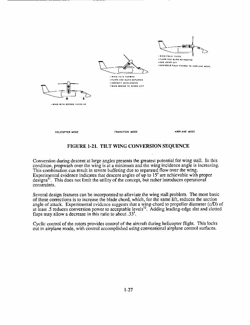
The Tilt Wing configuration alleviates download on the wing in hover by always keeping thewing edgewise to the propeller slip stream. However, this configuration can exhibit wing stallduring decelerating descent, resulting in additional power required and control problems duringconversion. The Tilt Wing converts from helicopter flight to fixed-wing flight by tilting thewing forward (Figure 1-21). The XC-142 and CL-84 successfully demonstrated conversion 9"10.
1-26
• WING TILTS FORV_RD
• FLAPS AND SLAT5 D[PLOYIEO
• AIRCRAFT ACCELERATES
• WING 8EOtN5 TO 9HAFIE LIFT
,FLAPS AND SLATS ftETRACTED
HUB LOCKS OU,
• CONTROLS FULLY PHA_EO TO AIRPLANE MODE
HELICOPTER MODE TRANSITION MODE AIRPLANE MODE
FIGURE 1-21. TILT WING CONVERSION SEQUENCE
Conversion during descent at large angles presents the greatest potential for wing stall• In thiscondition, propwash over the wing is at a minimum and the wing incidence angle is increasing•This combination can result in severe buffeting due to separated flow over the wing.Experimental evidence indicates that descent angles of up to 15° are achievable with properdesigns ]] . This does not limit the utility of the concept, but rather introduces operationalconstraints.
Several design features can be incorporated to alleviate the wing stall problem. The most basicof these corrections is to increase the blade chord, which, for the same lift, reduces the section
angle of attack. Experimental evidence suggests that a wing-chord to propeller diameter (c/D) ofat least .5 reduces conversion power to acceptable levels ]2. Adding leading-edge slat and slottedflaps may allow a decrease in this ratio to about .33 _.
Cyclic control of the rotors provides control of the aircraft during helicopter flight• This locksout in airplane mode, with control accomplished using conventional airplane control surfaces.
1-27
INITIAL TECHNOLOGY ASSESSMENT
Assessing technology consists of identifying current levels of technology and predictingimprovements achievable for a 2010 production aircraft. This implies that demonstration of thetechnology occurs about 2003. These dates are based on engine technology developmentconsistent with the IHPTET Phase II! milestones. Due to the nature of Task 1 and the large
number of concepts investigated, the assessment necessarily is broad in scope. Whereapplicable, goals of existing technology programs represent assumed advanced technologylevels, consistent with the time frame specified above.
Structures & Materials
Significant advances in structures and materials technology will enhance the development ofhigh speed rotorcraft. Areas of technology development include: (1) optimized use of compositestructures, (2) fail-safe design concepts, (3) manufacturing methods, and (4) new materials. Allof these technology areas will contribute to improved structural performance resulting in lowweight, damage tolerant, and durable structural designs.
Tailoring composite structures for stiffness and strength minimizes material and fabricationcosts, as well as reduces weight. Application of adhesive bonding technologies for structuraljoining, will minimize the use of mechanical fasteners. Solid laminate skins will also allowoptimized designs for improved structural performance.
Hybridization of materials will improve damage tolerance and durability, .and local application ofmultiple materials will be used to tailor stiffness and strength. Incorporation of fail-safe designapproaches, such as delamination arrestment concepts, will further reduce structural weight.
Advances in manufacturing technology will significantly reduce fabrication costs and willgreatly improve the reproducibility of composite structures. Thermoplastic fabricationtechniques, such as roll forming, will be available for large scale application. Employment ofintegral concurring methods will minimize the number of assembly operations required.
Hybridization of materials wilt improve damage tolerance and durability, .and local application ofmultiple materials will be used to tailor stiffness and strength. Incorporation of fail-safe designapproaches, such as delamination arrestment concepts, will further reduce minum-lithium (A1-Li)alloys under development show greater stiffness and lower densities than conventional aluminumalloys.
The above advances in structural materials and technologies have the potential to reduce
component weights between 10-25% depending on the particular system and application.Several examples have shown actual weight savings such as the Army's ACAP and Marine V-22programs. Weight savings through the use of composites have also been demonstrated oncomponents of the F-16, L1011, A310, and many other aircraft. Preliminary design studiesleading to full scale development of the Superteam's LH and McDonnell Douglas HelicopterCompany's MD-900 have shown potential weight savings on the order of 15-22%. In addition,conceptual design studies for the Air Force's SOF and A'Iq" air vehicles have identified potentialweight savings of 20-25% due to the use of composites. For the HSR study, a slightly lessoptimistic approach has been taken; 15% weight savings in primary structure and 10% weightsavings in secondary structure. The confidence level in attaining these weight savings is high
1-28
dueto lessonslearnedfrom theACAP/V-22programs,improvedcompositemanufacturingtechniques,andtruecompositedesignutilizing thebeneficialattributesof differentcompositematerials.
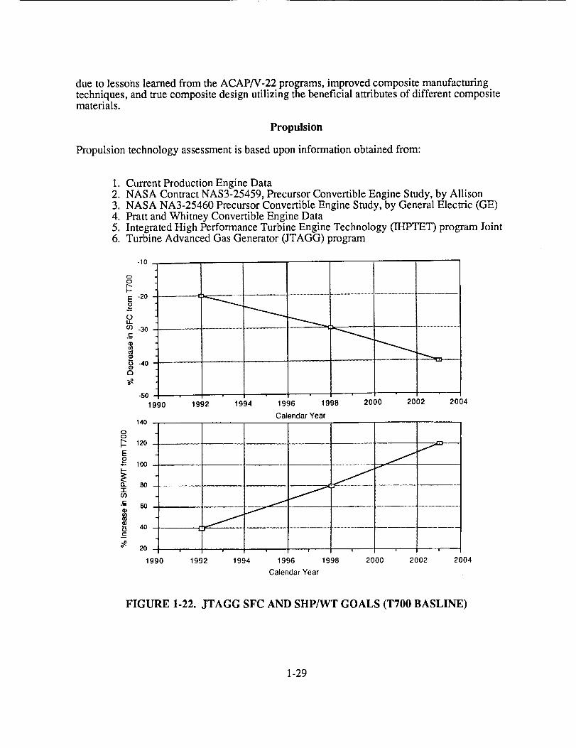
Propulsion
Propulsion technology assessment is based upon information obtained from:
1. Current Production Engine Data2. NASA Contract NAS3-25459, Precursor Convertible Engine Study, by Allison3. NASA NA3-25460 Precursor Convertible Engine Study, by General Electric (GE)4. Pratt and Whitney Convertible Engine Data5. Integrated High Performance Turbine Engine Technology (IH TET) program Joint6. Turbine Advanced Gas Generator (JTAGG) program
oO
I--
E
oOii00
i-
O
-10
-20
-30
-40
-50 ....
1990 1992 1994 1996 1998
Calendar Year140
2000 2002 2004
0C;
120
E2_- 100
80 "
•¢- 60
bt-
i
40
20
1990
J
i i g i i ! i
1992 1994 1996 1998 2000 2002 2004
Calendar Year
FIGURE 1-22. JTAGG SFC AND SHP/WT GOALS (T700 BASLINE)
1-29

The selectedhigh-speedconfigurationsrequireconvertibleengines,tilting engines,or turbofanengines.Thetechnologyfor tilting enginesis availablein theAllisonT406 turboshaftengineutilizedon theV-22. Convertibleenginefeasibilityhasbeendemonstratedby GE in a groundtestof amodifiedGeneralElectricTF34turbofanenginewith variableinlet guidevanes13.Otherfeasibleconvertibleengineconfigurationsconsistof: variablepitchfan,VIGV-VEGV fan,clutchedfan,andpropfan.However,therearenocurrentlyfundedconvertibleenginedevelopmentprograms.Therefore,theavailableenginesfor threeof thefive configurationsaretheAllison T406 family of turboshaftengines(6150SHPto 13000SHP)for theTilt RotorandTilt Wing configurationsandcurrentproductionlow bypassratio turbofanenginesfor theRotor/Wingconfiguration.TheFoldingTilt RotorandtheTrail RotorrequireConvertibleengineswhichdo notexisttoday.
Convertibleenginetechnologymustbedevelopedover the next fifteen years for the Folding TiltRotor and Trail Rotor configurations. The key technologies to be developed (depending upon
convertible engine configuration) are: high power, light weight torque converters and clutches,and engine conversion control system(s). Current engine technology must be developed toachieve the JTAGG goals of specific fuel consumption improvement of 40% and enginepower-to-weight improvement of 120% over TT00 technology (Figure 1-22). This will enablemission effectiveness improvement for all high-speed rotorcraft configurations. To meet thesegoals the Department of Defense and NASA are funding research and development of enginecomponents under the auspices of the IHPTET program.
4000-
Drive System
8
g
3Boo- CH-53Bo_
°3o0o V-22
2000- CH-47C _ .--_"" r
,5oo OH 60 _ -"'""'"- _ 30LB/HP
- _0 _ .--'-'"'"" -_ ART GOALS
,ooo- cH'46Ao XV-lSF---"UH 1 o _ °AH.64,_
o4 o;o ,doo .o'oo .o'oo ,ooooRated Power, (HP)
FIGURE 1-23. DRIVE TRAIN WEIGHT TRENDS
1-30

Drive Systemtechnologyassessmentisbasduponinformationobtainedfrom:
1. CurrentProductionHelicopterDrive SystemsDesigns2. V-22 Drive SystemDesign3. AdvancedRotorcraftTransmission(ART) ProgramTM
The Folding Tilt Rotor, Trail Rotor, Tilt Wing, and Tilt Rotor configurations require crossshafting, reduction gearboxes, speed increasers, and angle gearboxes. The technology for thesedrive systems currently exist and is demonstrated in the V-22 development program. Currentdrive system weight-to-power ratio is .40 lbs/hp as shown in Figure 1-23. The Rotor/Wing, doesnot require gearboxes or cross shafts, while there is a requirement for ducting, it is substantiallylighter in weight. Significantly, it possesses a power transmission efficiency of about 50%.
Future mechanical drive system technology is dependent upon the Advanced RotorcraftTransmission (ART) program which has goals of:
1. 25% Reduction in drive system weight2. 5000 hours MTBR3. 10dB reduction in noise
Based upon a recent ART Program Review in October 1989, there is indication that the 25%reduction in weight and 5000 hours MTBR is achievable. To meet these goals, transmissioncomponent technology must be developed in the areas of gears (high pitch line velocity), shafts(high-speed and supercritical), ceramic bearings, housings, seals, positive engagement clutches,advanced lubrication systems, and gearbox diagnostics. Additionally, analytical tools andmanufacturing methods require further development to complement component development.All these goals are directly applicable to high speed rotorcraft designs. The weight-to-powergoal of .30 lbs/hp is anticipated for 2010 IOC high-speed rotorcraft transmission designs. Drivesystem efficiency will increase a negligible amount due to new lubricants and gear and bearingmaterials. Future drive system technology development is considered to be of medium risk.
Figure 1-23 depicts the transmission weight trends for current and advanced rotorcrafttransmissions based on rated power transmission. Representative rotorcraft are plotted forcomparison. The V-22 falls above the current technology line due to the high torque resultingfrom reducing RPM in cruise. Helicopters with relatively constant tip speeds fall close to the .4lb/hp line. High-speed rotorcraft will likely not follow the current trends, but a reduction inweight of 25% will account for advanced technology gains in this area.
Aerodynamics and Acoustics
High-Speed Airframe Aerodynamics- Airframe aerodynamics in high-speed cruise affectthe success of a high-speed rotorcraft. For high-speed forward flight, the major emphasis inairframe aerodynamics is to increase the drag divergence Mach number of the wing. Otherconfiguration-dependant design requirements may limit both wing thickness ratio and themaximum allowable sweep, leaving mainly wing loading and altitude to define thecompressibility drag of the wing in high-speed cruise. Additionally, airframe integration of suchcomplex configurations may create adverse aerodynamic interference at high speeds.
1-31

Rotor Acoustics and Aerodynamics- Both acoustics and aerodynamics define the
capabilities of the rotor in helicopter flight. Acoustic signatures limit the tip speed for civil andmilitary operations. For the configurations that utilize the rotor for helicopter flight only, themaximum blade loading determines the capabilities of the rotor, while Figure of Merit indicatesrelative efficiency. However, for configurations that utilize the rotor for both helicopter andforward flight, like the Tilt Rotor and Tilt Wing, the cruise propulsive efficiency significantlyinfluences the design. Additionally, rotor performance and rotor/airframe interactions in hoverbecome important for low-speed handling qualities and maneuvering capabilities. Hoverdown-load varies between concepts, from near zero for Tilt Wing to 12% for the tilting/folding
rotor concepts.
Collectively, the current technology in aerodynamics and acoustics requires creative design tosatisfy high-speed requirements. A 450-kt speed requirement of the high-speed rotorcraftcompetes with current subsonic transport aircraft. However, the added complexity of a low-speedmission limits the available parameters with which to optimize the aircraft. A 450 KTASrotorcraft will take aerodynamics and acoustics to the limit of current technology, and to ensurethe success of an aircraft with such capabilities, advanced technology must show significant
improvements over current state-of-the-art.
Aerodynamics of High-Speed Forward Flight
20
<
O
¢J
15
lO
O NASA Hiqh-SpeedRotorcra?lt
::i::i::Eiiii_E!_i!_;iii!_!_!;ii!i:.,.'::!:i:_:i:i:i:i:!:i:i:i',:::::::::::::::::::::::::::::::::::::r:::::::::::.:.:.:,:,:.:,:.::.:,::...........................................
."_ :::::::::::::::::::::::::::::::::::::::::::::: (_! i::::: ::::::_:_ 737 :::::::::::::::::::::::::::::::::::::::::::::::::::::::::::::::::::::::::::::::::::::757 :;:;:_:;:_:_:_:_:_:_:
::::::::::::::::::::::::::::::::::::::::::::::::::::::::::::::::::::::::::::::::::::::::: ,, ::::::,,:-,.,,:..+::,:, :+:+:,:::::::::::::::::::::::::::::::::::::::::::::::::::::::::::::::::::::::::::::::::::::::::::::::::::::::::767 :::::::::::::::::::::::::::::::::::::::::!::i
:_,_._:_i_i_iiiii_?ii_i_i_ii_ii_iii_i_i_i_i_!i_i_iii_iiiii_ii!_i_ii_!:i!!_:i_:!_i_i_!_a:a.:i__i_!!_:!':!!!_ii!i!ii:::iii:!
Currant Transport Aircraft
5! I
0.70 0175 0180
Cruise Mach Number
0.85
FIGURE 1-24. HIGH-SPEED AIRFRAME AERODYNAMICS
1-32

Configurationrequirementsof high-speedVTOL aircraftdictatetheaerodynamictechnologyrequiredto obtain 450-kt flight. Figure 1-24 shows a survey of existing high-speed subsonictransports revealing the basic dilemma for high-speed rotorcraft. Minimizing wing weight, whilemaintaining required stiffness to tolerate wing bending and torsional moments, drive the wingthickness-to-chord ratios considerably higher than found conventional transport aircraft.Limiting the wing sweep to 20 ° on concepts incorporating tilting rotor pods at the wing tipscauses the wing design point to lie far from the locus of existing transports. This implies that,without structural breakthroughs to reduce thickness, the wing airfoil section designrequirements are considerably more stringent than requirements for current state of the arttransports.
0.80
e_E 0.75
Z
r.-ot_
o 0.70e-
h.
>.m
a
0.65Q
__ TRC Study
CL= 0.35, A = 10°
_Current Slate-of-the Art
"_,_C L =O.O, AeliO )
0.601 • • v • --
o.15 (}.20 02
Wing Thickness Ratio
FIGURE 1-25. MDD BOUNDARIES OF HIGH-SPEED ROTORCRAFT WINGAIRFOILS
During the initial concept evaluation of the Trail Rotor Convertiplane (TRC), McDonnellDouglas Corporation (MDC) initiated a task to design an 18% airfoil section capable of flying at0.735 Mach number at 0.35 lift coefficient. A series of airfoils were tested in the Boeing WindTunnel and demonstrated improved characteristics as shown in Figure 1-25 Is. However,achieving 450 KTAS with a design using the TRC airfoil and wing sweep limits of 20' stillplaces constraints on wing loading and maximum altitude. Removing these design constraintsrelies on further improving the TRC section. Further investigation into the trades required forwing thickness, sweep, weight and aerodynamic improvement must follow this study.
1-33

Prop/Rotor Performance
Feasibility of any configuration that employs a single propulsive device for both hover and forhigh-speed forward flight relies on the efficiency of the lifting/propulsive device in both flightmodes. Which design condition is more important depends on both the configuration and themission. Since the disk loading, and thus the hover power is low, the 450 KTAS cruise
requirement sizes the eng!ne on most of the configurations. Low propulsive efficiencies incruise result in larger engines and in heavier aircraft. Although low hover efficiency will notresize the engines, it results in more fuel used during helicopter flight and could be important, ifa mission requires a large segment in helicopter mode. Even though the cruise propulsiveefficiency has greater impact than the hover Figure of Merit, the resulting rotor design should notpenalize the performance in one flight mode to obtain exceptional performance in the other.
o.g
_ 0.8-
• 0 1Ok STD Conditionl
,_ 0.7 - o §k STO Condition|
"5o. 0.8 Helical Tip Math Numbero
o.
>.o¢o'13
"5O.
2a.
0.6200 360 ,;60
Vcr. (ktns}
0.8
07-
06-
0.5
0.4
0.3
0.6
i1=
i0
,t-
500
Tip S_
08 Helicsl Tip Msch Number
,, ,,.VT HOVER " 750 fps
' , i09Rotor Tip Speed Ratio, (VT/V T HOVER)
0.80
0.78 -
0.76
0.74
0.72
0.70 ,
0
Vcr =" 460 KTAS
0.8 Helical Tip Mech Number
(l/D)cr -- II
1 2 3 4 5 8 7 8 g
Cruise Altitude. (1000 ft)
Rotor Characteristics- 5 Rectangular Blades- 30 deg Linear Twist- 25 psf Hover Disk Loading- Distributed XV-15 and
HH-06 Airfoils- 0.1333 Hover (CT/_r)
0.80 Hover Figure of Merit
IO
FIGURE 1-26. PROP/ROTOR CRUISE PERFORMANCE
A preliminary study investigated the effects of cruise velocity, altitude, and tip speed onpropulsive efficiency to identify the limitations on forward speed capability of a prop/rotor withadvanced airfoils. Figure 1-26 shows the results of this study. At around 400 KTAS the rotorreaches an "efficiency divergence". Above this speed the propulsive efficiency decreases veryrapidly for a constant helical tip Mach number of 0.8. This occurs due to the airfoils reachingdrag divergence Mach number at relatively high CL. The effect of altitude is less severe,reflecting the speed of sound change. For p.rop/rotors to operate at these speeds, a reduction in tipspeed must occur. Assuming a representatxve hover tip speed of 750 fps, obtaining a propulsiveefficiency of .725 requires reducing the tip speed by 45%. Further reduction results in little gain.This lower tip speed results in the blade sectzons operating at more optimum angles of attackwith respect to drag divergence, and therefore with better efflciencies. Reducing the rotationalspeed on a direct shaft-driven rotor will force the engine to operate at non-optimum conditions,
1-34

increasingthefuel flow for cruise.Oneway to maintaintheengineefficiencyin cruiseis toemployatwo-speedgearbox to keeptheenginerotatingat thesameoptimumspeed.Thetwo-speedgearboxaddscomplexityandweightto thedrivesystem,thus,requiringa trade-off.
Besidestheperformancebenefitsof lower tip speeds,reasonableacousticlevelsrequirelower tipspeeds.Limiting thehelicaltip Machnumberto 0.8to ensuregoodacousticsignatures,requiressignificantlyreducedtip speedat450KTAS.
Developingadvancedairfoils with improveddragdivergencecharacteristicsor employingtipsweepseemto be theonly waysto improvepropulsiveefficienciesin high-speed(above450KTAS) flight withoutresortingto elaborateschemesto reducerotor radius. This requirementmayconflict with hoverrequirements,thusposingadifficult problem.Thetip-speedreductionrequiresatwo-speedgearboxto maintaingoodengineperformance.Thefuel weightsavedbyimprovedefficiency morethanoffsetstheweightpenaltyof thetwo-speedgearbox.
This studyusesXV-15 rotorcharacteristics(modifiedat thetip) asa baseline16.Usingcurrenttechnologyairfoils resultsin arotor with ahoverfigureof meritof 0.8andapropulsiveefficiencyof 0.725for a 450KTAS cruiseat 10,000feet. The 10,000feetdesignpointrepresentstheoptimumtilt-rotor design.At cruisealtitudesmuchgreaterthan10,000feet,requiredpower increasessignificantly.
Conversion Axis - Ceter of Gravity Relationship
EAL CRUISE
HOVER CO
.o1 1] ORIVtAE,
1 I CONVERSrON AXIS
IDEAL CRUISE CG
FIGURE 1-27. CONVERSION AXIS - CENTER OF GRAVITY RELATIONSHIP
(geometry exagerated for purposes of illustration)
1-35
Theconversionaxis - centerof gravityrelationshipis of primaryconcernfor theFoldingRotor,Tilt RotorandTilt Wing concepts.Sincewingsfor theseconceptsuserelatively thick airfoilsections(approximately18%),highly sweptwingsarerequiredfor highspeedflight to avoiddragdivergence,ensurerotorbladeflappingclearance,andto minimizerotoroverhangdistancefrom thewing torsionalaxis. As illustratedin Figure 1-27,wingswith little or nosweepallowtherequiredconversionaxisto lie within thewing planformandaccommodatethestaticmarginof theaircraft. Thisallows theuseof aconventionalwing/tailconfigurationsuchastheV-22,As thewing is sweptforwardor aft, theidealconversionaxis thataccommodatesthestaticmarginlies outsideof thewingplanformcausingdifficulty in providingadrivepathor requiring
• axis.offset/skewedgearingto matchthecenterof gravityandconversion " If offset/skewedgearingiseliminateddueto complexity,theconversionaxiswill lie forwardandexceedthestaticmarginof theaircraftasillustratedin figure 1-27for forwardsweptconfigurations.Foraftsweptwingstheconversionaxiswill lie aft andexceedthestaticmarginof theaircraft. Thestaticmarginconstrainsthecenterof gravity in acruisecondition,which mayconflictwith theconversionaxisrequirementsonhighly sweptwingsfor anytilt concept,Resolvingthisconflictrequirestheuseof large,highly loadedhorizontaltailsand/orcanards.Thisproblemappearsworsefor anaft sweptTrail Rotor,wherethestaticmarginwill alwaysbe forwardof theconversionaxisrepresentinganunstableconfigurationwithout a largeuploadedhorizontaltail.Theforward sweptfolding tilt rotorappearsmorepromisingdueto thecenterof lift locatedaftof theconversionaxis. Theconfigurationis easilymadestablethroughtheuseof acanard.However,theeffectof thecanardon rotorperformanceor rotoroncanardperformanceremainsto bedeterminedandcouldcauseunforeseenproblems.
By takingadvantageof severalpossibledesignideasbelow,thesecritical relationshipscanberesolvedwithoutplacingunrealisticconstraintson theconfiguration.Usinghigherstrengthmaterialsallowsthinnersectionsanddecreasestherequiredwing sweep.Thiswill help to aligntheconversionaxisandcenterof lift. Incorporationof advancedactiveflight controlswillincreasetheallowablecenterof gravitytravelfor thehighly sweptforwardor aft configurations.Themethodof tilting rotorpylonsandwingscouldbechangedto makeallowancesfor thecenterof gravity shift andthecenterof lift for bothhover/lowspeedandcruiseflight.
Rotor/Wing Helicopter and Airplane Flight Requirements
The Rotor/Wing promises the advantages of the helicopter for low speed flight combined withthe high-speed capability and cruise efficiency of the jet airplane. The fundamental compromiseassociated with the Rotor/Wing concept is between the conflicting requirements of conversionand rotary wing flight modes.
The Rotor/Wing concept utilizes the center body of the rotor disk to provide a liftingsurface during conversion. The conversion requirements dictate that the center surface be aslarge as possible, so that conversion can occur at lowest possible flight speed. The helicoptermode requires that lift- producing blades sweep as much of the disk as possible. Theseconflicting requirements are shown qualitatively in Figure 1-28.
1-36

Determined by
Determined by
Minimum Airplane
Speed
ALLOWABLEGROSS WEIGHT
Geometry of vConventional Rotor
\
CENTERBODY
Geometry Similar
to a Delta Wing
.8 i .0
RADIUS/TIP RADIUS, r/R
FIGURE 1-28. CONFLICTING HELICOPTER AND AIRPLANE FLIGHT
REQUIREMENTS
The horizontal scale of this figure, center-body radius to blade tip radius, represents theconfigurative geometry of the Rotor/Wing. The left and fight hand margins represent twoconflicting requirements, helicopter on the left and airplane on the right.
The Rotor/Wing's lifting ability is depicted on the vertical scale. The downward sloping curverepresents the lifting ability in hover flight for constant installed power. The larger the bladespan in proportion to the total radius, the greater the lifting capacity in hover. As the center-bodyarea increases and blade span decreases, the hover lifting ability decreases until at the right handmargin, no lift can be produced by the bladeless center-body. The lifting ability of thecenter-body surface during conversion determines the upward sloping curve. At the left margin,there is no surface area to produce lift, but as the surface area increases, the lifting ability in thismode increases rapidly. The two lines represent limits of the conflicting requirements abovewhich the Rotor/wing concept cannot operate.
1-37

Theconfigurationwith thelargestlifting ability andwithin theconstraintsimposedby theserequirementsliesat the intersectionof thetwocurves.This intersectionlies betweenr/R ratiosof 0.4 and0.7. Theexactlocationof theapexdependsuponthepowerinstalled,thehoveratmosphericconditions,thebladechordandconversionspeed.
Dynamics and Aeroelasticity
Each of the five rotorcraft concepts being considered, should be considered from anaeromechanical perspective. More appropriately, in view of the need for full authority automaticflight controls to manage each vehicle during conversion, an aeroservoelastic approach should beused. Some problem areas, such as surface flutter or divergence, are shared by most or all fiveconcepts while others, such as wing/rotor interactions and rotor instabilities, are applicable onlyto some or one of the designs.
Divergence and Flutter- With the exception of the Rotor/Wing concept, all the desi.gnsincorporate large rotor or proprotors located at the end of a medium-to-high.aspect ratio wingdesigned for cruise efficiency. The addition of this large tip inertia to the wing can reduce therotational frequency coalescence with a primary wing bending mode. The Folding Tilt Rotorand Trail Rotor, additionally, imply a fairly large center of gravity shift aft at the tips when therotors fold, exacerbating the flutter problem. A fundamental design compromise must be madebetween increased torsional stiffness, pushing toward thicker wings, and airplane modeefficiency, for which thinner sections are desired. The very high wing stiffnesses required toallow for "jump" (>>lg) vertical takeoffs, however, could obviate the need for this compromise,as could an advanced active electrohydraulic flutter suppression system 17.
The Tilt Rotor, Tilt Wing and Rotor/Wing share a forward swept wing design in the airplanemode, which can lead to wing divergence at high speeds. For the Rotor/Wing, which, ofnecessity, has a substantial inboard structure to support and enclose the reaction drive ducting,and for the Tilt Wing, which has more propeller-like proprotors and therefore needs less wingsweep, this probably will not be a problem. The Tilt Rotor, on the other hand, especially theFolding Tilt Rotor, require significantly more forward wing sweep to avoid wing-rotor contact atreduced RPM under high loads. Again, a compromise must be made between increased torsionalstiffness and airplane mode efficiency. Another possibility is to build in a beneficialbending-torsion couplings in the wing structure using advance tailored composite materials.Wing divergence should not be a problem for the aft-swept Trail Rotor design.
Rotor/Proprotor Instabilities- The Tilt Wing and two Tilt Rotor designs, which are stiffin-plane (i.e., the fundamental in-plane modal frequency is greater than the rotational frequency)could share the problem of whirl mode instabilities, which occur when the thrust vector motioncouples with wing torsional bending. Engineering cures for this problem, however, are wellestablished from the XV-15/V-22 program and include both particular design features to reducethe tilt of the thrust vector and active suppression of the motion using cyclic pitch TM. A major
advantage of the stiff in-plane arrangement, however, is that it eliminates the possibility ofground or air resonance instabilities.
TheTrail Rotor concept might use a soft in-plane rotor to reduce rotor weight. Since thisrotor would tilt aft, not forward, and be under light loading at the time, whirl mode instabilities
are probably not a concern here. However, as mentioned above, the soft in-plane rotor is subjectto ground and/or air resonance and, unlike a standard helicopter, in a Trail Rotor design the wingand fuselage flexibility will play a large role in the couple motions. Again, careful wing and
1-38

rotordesignis requiredtoremovethispossibility. Becausethewing participatesstrongly,however,it maybepossibleto actuallyusetheverticalwingmotionto introduceadditionaldampingby couplingtogetherthebladelagmotionwith thestronglydampedcollectiveflapmotion.
Both stiff in-planeandsoft in-planerotorscanbesubjectto flap-lag-torsioninstabilitiesinforwardflight. Thesourceandseverityof this typeof instability is highly dependenton theexactrotor design,especiallythebuilt in geometricandstructuralcouplingsin therotorblademotions. It is, therefore,outsidethescopeof thispreliminaryconceptreview,but mustbecarefully investigatedfor eachideaduring thedesignphase.
Thetwo foldingconcepts,theFoldingTilt RotorandtheFoldingTrail Rotor,mustundergolargerapidreductionsin rotor rotationalspeedandfinally stoptherotorsatfairly highvehicleairspeeds.Controlandstabilityof therotor duringthetilting andfoldingportionsof theconversionfrom rotor-borneto wing-borneflight andviceversaarealmostunexploredareas,bothexperimentallyandanalytically. Theyentail,therefore,highertechnicalrisk thaneithertheTilt Wing or thestandardTilt Rotorconcept.Analyticaltoolscapableof realisticallysimulatingthis typeof environmentareonly now beginningto becomeavailableandarenotyet verified.Mostprobably,this typeof designwill requireadvancedautomaticrotor controlandstabilityaugmentationsystemsthroughouttheconversionprocess.
1-39

TECHNOLOGY TRADE STUDIES
Measures of Effectiveness
Establishing a means of comparative analysis between the concepts requires a derivation ofmeasures of effectiveness. These measures evaluate the concepts beyond the vehicle attributes
of weight, speed, range and payload. Grouping these attributes together establishes parameterswhich evaluate the overall vehicle effectiveness. These measures allow combinations of strongand weak attributes to further define the effectiveness and economy of a concept. For instance, a
high-speed, fuel inefficient concept may be more economical than a slower, fuel efficient one.Examining the individual attributes independently may not resolve the economics of the
problem.
Five measure of effectiveness (MOE) establish a baseline for a comparative evaluation of the
concepts:
1. Lift/Drag (L/D)- This ratio depicts the lifting efficiency of a particular aircraft.A high value results in less thrust required for a given gross weight, indicating moreeconomical operation. This parameter varies with both gross weight and drag changes.
2. Productivity- A measure of the capability of the aircraft to deliver large amountsof payload in a given time, either by large amounts per sorties or small amounts through
many sorties defines productivity.. Normalizing by the empty weight provides a furtherindication of economy, since maintenance and acquisition costs generally follow the trend
in empty weight. It is defined as payload x velocity/empty weight.
3. Payload Delivery Efficiency (PDE)- This indicates the efficiency of deliveringpayload from a cost point of view. A higher value implies greater payload delivery for lessfuel, hence less cost. Besides cost, it also reflects the degree of logistics support requiredfor an airlift mission. It is defined as payload x range/fuel required.
4. Payload/Range: A measure of the concept's ability to trade payload for fuel, thisparameter demonstrates range flexibility. At the same gross weight, range is extended byreplacing payload with fuel.
5. Specific Range: This measures a concept's range efficiency at a specified grossweight and altitude. The concepts' MOE were used to conduct three trade studies toinitially assess the effects of technology on the concepts. The initial trade study comparedthe concepts at current levels of technology; the second examined the effect of eachadvanced technology on each concept; and finally, the last trade study compared all the
concepts at advanced levels of technology.
Current Technology Study
Productivity- For a given mission, the weight empty influences this measure ofeffectiveness the greatest.
1-40

Figure 1-29 depicts productivity versus flight speed for each of the concepts. For a specifiedconfiguration, these values of productivity were computed at design gross weight, for the generic600-nm mission flown at the optimum altitude. The calculations reflect fuel and rangeallowances for take off, climb, descent, and landing with 10% fuel reserves.
100
A
.D 80
t/)
_ 60
.__• 40
0
"1o2 20-
0
200
x
I I ! I
250 300 350 400
Vcr, (KTAS)
o Tilt Rotoro Tilt Wing
Folding Tilt Rotor÷ Propfan TrailRotor× Turbofan Trail Rotor* Rotor/Wing
I
450 500
800
600-
E¢.-
& 400-
u_aa.
200-
0 I I / I 1
200 250 300 360 400 450
Vcr. (KTAS)
- Optimum Altitude- 600 nm Range- Fuel Allowances For
10% Reserves
50O
FIGURE 1-29. MEASURES OF EFFECTIVENESS - CURRENT TECHNOLOGY
The graph shows that the Rotor/Wing is the most productive at flight speeds greater than 250KTAS, followed by the Tilt Wing. The Weights Summary tabulated in Appendix A shows theseconfigurations have the lightest weight empty, substantiating the strong influence of emptyweight on productivity. Since the Tilt Rotor weighs slightly more than the Tilt Wing, itsproductivity is less than that of the Tilt Wing. The folded-rotor concepts, Folding Tilt Rotor,Turbofan Trail Rotor and Propfan Trail Rotor, are the least productive because their dual
propulsive devices increase their weight empty.
Payload Delivery Efficiency- For a given mission radius, the PDE is most affected by thefuel efficiency of the configuration. The payload delivery efficiency, depicted as a function offlight speed for each of the concepts, is based on design gross weight and 600-nm mission flownat the optimum altitude for each configuration. The useful load, fuel plus payload, is heldconstant for each configuration, and the mission fuel reflects allowances for take off, climb,descent, and landing with 10% reserves.
The Propfan Trail Rotor and Rotor/Wing have the greatest PDE for flight speeds greater than350 KTAS because of their high-speed cruise efficiency. At low speeds, the Rotor/Wing's PDEis poor, while the Tilt Wing and Tilt Rotor have the greatest PDE. However, the rotor'spropulsive efficiency decreases as flight speed increases, and the PDE of these concepts also
1-41
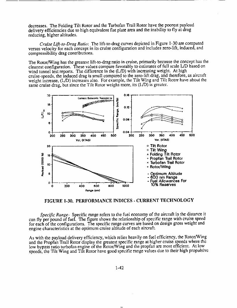
decreases.TheFoldingTilt RotorandtheTurbofanTrail Rotorhavethepoorestpayloaddeliveryefficienciesdueto highequivalentflat plateareaandtheinability to fly at dragreducing,higheraltitudes.
Cruise Lifi-to-Drag Ratio: The lift-to-drag curves depicted in Figure 1-30 are computedversus velocity for each concept in its cruise configuration and includes zero-lift, induced, andcompressibility drag contributions.
The Rotor/Wing has the greatest lift-to-drag ratio in cruise, primarily because the concept has thecleanest configuration. These values compare favorably to estimates of full scale L/D based onwind tunnel test reports. The difference in the (L/D) with increasing weight. At high
cruise-speeds, the induced drag is small compared to the zero-lift drag, and therefore, as aircraftweight increase, (L/D) increases also. For example, the Tilt Wing and Tilt Rotor have about thesame cruise drag, but since the Tilt Rotor weighs more, its (L/D) is greater.
B
_Iv
30--
16"
10-
6-
0
200
Current Subsonic Tra,lspo_tu
0.10_
E
_ 0.12-
&
C
u 0.08-
0.04
600 200250 ' i300 360Vor. (KTAS)
,°t
10
t.
0 200 400 (_00 800 1000
Rano* (nm}
1 .... I ......... I25o 3so ,ooVcr, (KTAS)
- Tilt Rotoro Tilt Wing
Folding Tilt Rotor* Propfan Trail Rotor× Turbofan Trail Rotoro Rotor/Wing
- Optimum Altitude600 nm Range
- Fuel Allowances For10% Reserves
FIGURE 1-30. PERFORMANCE INDICES - CURRENT TECHNOLOGY
Specific Range- Specific range refers to the fuel economy of the aircraft in the distance itcan fly per pound of fuel. The figure shows the relationship of specific range with cruise speedfor each of the configurations. The specific range curves are based on design gross weight andengine characteristics at the optimum cruise altitude of each aircraft.
As with the payload delivery efficiency, which relies heavily on fuel efficiency, the Rotor/Wingand the Propfan Trail Rotor display the greatest specific range at higher cruise speeds where thelow bypass ratio turbofan engine of the Rotor/Wing and the propfan are most efficient. At lowspeeds, the Tilt Wing and Tilt Rotor have good specific range values due to their high propulsive
1-42

efficiencies. As the speed increases, turbofan engine performance improves, thus, the specificrange of the Folding Tilt Rotor and Turbofan Trail Rotor approach that of the Tilt Wing and TiltRotor.
Payload�Range- The payload/range computations are based on design gross weight and a
mission flown at each concept's optimum altitude. The calculations utilize a fixed design usefulload, fuel plus payload, and the range calculations reflect fuel and range allowances for take off,climb, descent, and landing with 10% reserves. The curves do not intersect at the 600-nmrange/4500-1b payload design point because the analysis is based on constant enginecharacteristics determined for the design gross weight.
The Propfan Trail Rotor and the Rotor/Wing have the best payload/range characteristics. Sincethe obtainable range is a function of the aircraft's specific range, those aircraft with greaterspecific range values will have better payload/range characteristics. Following the Propfan TrailRotor and Rotor/Wing are the Tilt Wing, Tilt Rotor, Turbofan Trail Rotor, and Folding TiltRotor, respectively. The concepts possessing the greatest range capability allow most flexibilityin long range missions, particularly for ferry type missions.
0.15
Advanced Technology Impact
SPECIFIC RANGE PAYLOAD DELIVERY EFFICIENCY
0.4 ¸
0.2
0
-0,2
o.8
0,4
0.2
EFFECTII CALCULATED M 4|0 KNOT8
FIGURE 1-31. EFFECT OF REDUCED SFC
1-43

Thesecondstudyexaminedtheeffectof eachtechnologyareaadvancementachievablefor a2010IOC aircraft. Using individualtechnologyareas,andresizingtheconceptfrom thebaselinecurrenttechnology,resultedin anassessmentof theeffectof eachtechnologyareaoneachconcept.This allowedacomparativeassessmentof technologydevelopmentpriority.
Effect of Reduced SFC (-25%)- Reduced SFC, due to advancements in engine technology,significantly affects the attributes of all configurations. Figure 1-31 depicts the relation of abaseline current technology aircraft with one that benefits from improved SFC only. Specific
range and payload delivery efficiency show the most significant improvements, since theseparameters relate directly to fuel efficiency. Productivity improvements result due to lowerempty weight achieved when the structure carries less fuel. The more fuel efficient enginesreduce the gross weight of all concepts through the combination of lower structural weight andless fuel weight. For the same percent improvement in SFC, the Rotor/Wing appears lessaffected. This occurs because a large component of empty weight in the other concepts consistsof the drive system. A reduction in overall weight reduces the power transmitted by this system
and its weight follows. Therefore, the concepts using drive systems incur the greatest percentageimprovement.
SPECIFIC RANGE PAYLOAD DELIVERY EFFICIENCY
°t0,4
0._
O.II
DESIGN GROSS WEIGHT
II
0.4
0.2
0
EFFECTS CALCULATED AT 4|0 KNOTII
FIGURE 1-32: EFFECT OF REDUCED ENGINE WEIGHT
1-44

ImprovedSFCimpactsdirectoperatingcostssignificantly,dueto thelargeimprovementsinpayloaddeliveryefficiency. Acquisitioncosts,assuminga$/lb relation,shoulddecreasefor allconceptswith reducedSFC.
Effect of Reduced Engine Weight (-36%)- Reduced engine weight, due to advancements inengine technology, affects the attributes of all configurations. Figure 1-32 depicts the relation ofa baseline current technology aircraft with one that benefits from reduced engine weight only.Specific range, and payload delivery efficiency both increase due to reduced fuel consumptionresulting from overall reduced structure weight. This will then reduce power required andresizes the engine to a smaller one. The cascading effect on structural weight is responsible forthe improvements in productivity shown.
SPECIFIC RANGE PAYLOAD DELIVERY EFFICIENCY
0.4
0.2
C
-o.2
m mmm m_m___
rift rltV _OtOmWa pnoPF_ TUnIOrAM mOVOMMOrOn WlUQ TILT TmAIL TMAIL WlNa*
uovon _oroR mOrom
0,4
0.2
0|m .....mm m _
TILT TILT fOLDINg PMOPrAN TU ItIOFAN MOTOMAOVOm WINe TILt TmAIL TmAtL WlHI'
MOrOn mOTO_ morom
PRODUCTIVITY DESIGN GROSS WEIGHT
rltTMOrOn
rlLr ¢OLO_NO p hop P'AN TUnlOFAH noTol_wlNo rlLr TI_AIt Vm*l_ _INO"
wora_ nOVOn _OTOm
o.e[i
0.4
o.',
c
• NOT AFFECTED BY DRIVE SYSTEM WEIGHT
EFFECT8 CALCULATED _ 480 KNOT8
FIGURE 1-33. EFFECT OF REDUCED DRIVE SYSTEM WEIGHT
Effect of Reduced Drive System Weight (-25%)- Reduced drive system weight, due toadvancements in component technology, affects all configurations except the Rotor/Wing. Thisis the result of the Rotor/Wing concept utilizing reaction drive in place of a mechanical drivesystem. Figure 1-33 shows the relation of a baseline current technology aircraft with one thatbenefits from reduced drive system weight only. Specific range and payload delivery efficiency
1-45

increase due to reduced fuel consumption resulting from both reduced structure weight andreduced power requirements. Reduction of power requirements secondarily affects engine sizeand drive system weight. Productivity improvements result due to lower empty weight achieved.
Effect of Improved Aerodynamics- Improved aerodynamics incorporates two main areas:airframe aerodynamics and proprotor propulsive efficiency. Improvement in both areas directlyaffects required mission fuel and indirectly affects the weight empty. Figure 1-34 depicts theeffect of improved aerodynamics.
0[04
0.2
SPECIFIC RANGE
....i R1 m__
PAYLOAD DELIVERY EFFICIENCY0.e
0,4
0.2
O
TI_ TIL¥ FOLDIHQ PRaPFAN T_MIOFAW ROTONMOTOm Will tILT TIAIL TNAIL WIMm*
navan mOTOA moron
TILT Tl_t VOLOINQ pnOPFA# VUneOFAn novaenavon WUNe _ULV TmAIL TXAIt W_Um "
nQvOM nOTOn nov0n
PRODUCTIVITY DESIGN GROSS WEIGHT
°tO.4
02
0._1
• NOT AFFECTED BY IMPROVED AERODYNAMICg
EFFECTS CALCULATED AT 480 KNOT8
FIGURE 1.34. EFFECT OF IMPROVED AERODYNAMICS
Improved airframe aerodynamics includes increasing the wing drag-divergence Mach number atthe cruise CL by 5% at the required cruise speed, reducing thrust and hence fuel. Improvingpropulsive efficiency of the proprotor by 10% at 450 KTAS reduces the fuel required toaccomplish the mission. The reduced fuel consumption for a given mission increases thepayload delivery efficiency of all the concepts, with the greatest improvement occurring forconcepts driven by proprotors. These concepts benefit through the combination of drag reductionand improved propulsive efficiency.
1-46

Aerodynamic improvements do not affect the Rotor/Wing in the context used thus far. Dragreduction may occur to the airframe which improves its efficiency. Unfortunately, unlike otherconcepts, hover requirements size its engines, so no reduction in engine weight occurs with areduction in cruise thrust. Any weight savings results from reduced fuel consumption. Theaddition of circulation control, in fixed wing flight only, would improve the cruise efficiency ofthe elliptical airfoils and should be relatively easy to accomplish. This possibility was notexplored in Task 1.
Specific range and payload delivery efficiency, due to their dependance on fuel show the greatestimprovement. Productivity increases as a result of reduced structure weight with less fuel.
0.4
0,2
SPECIFIC RANGE
l_l !
t_-0,2 ___0 i i .... ] .... _---tILT TILT ¢OLDINO pnoP FAll Vu R|a_^ll noran
nO'rOll Wllle TILt TIIAIL TllAIL WIN0AOTOI_ navon I_or0 n
0,4
0.2
-0.2
PRODUCTIVITY
0.4
0.2
0
-0.2tILT TILl" FOLDIN G pllOp FAll TU plIO_'AH RO?OFt TILT TIL, FaLOtNa PROllFAN TURBOFAN ROTOR
maroll WtNO TILT TllAIL 'PAIL Wl#a mOTOm Wfml TILT 'PAIr ,mAlt YrlllOmOTOll mOVall llarall _ovo_ _aron uovon
EFFECTS CALCULATED AT 480 KNOTS
FIGURE 1-35. EFFECT OF REDUCED STRUCTURE WEIGHT
Effect of Advanced Structures- The use of advanced materials and manufacturingtechniques affects the vehicle attributes by reducing primary structural weight by 15% andsecondary structural weight by 10%. This percentage is an approximate average with variousstructural components varying more or less depending on their function. Components whichrequire metal obviously can not take advantage of light-weight composite materials.
1-47

Thereductionin weightemptyimprovesall vehicleattributes(Figure1-35).A lighterweightemptyresizestheaircraft,reducingareasof majordragcontributorssuchasthewingandempennage.As aresult,completingthemissionrequireslessfuel which improvesbothspecificrangeandpayloaddeliveryefficiency. Productivityreflectsaslightly greaterincreasedueto theinverserelationshipwith weightempty.
Conceptsemployingthemostcomplexdrive/propulsionsystemsbenefitthemostfrom reducedstructuralweight. While thesesystemsmaynotbedirectly affected,theresultinglower grossweight reduces power required. This in turn, lowers both the propulsion and drive systemweights.
The results of this study show that the largest overall impact of reduced structure weight willoccur on productivity which indicates maintenance and acquisition cost reductions. Directoperating costs associated with payload delivery efficiency will also decrease.
1GO
Advanced Technology Study
1000
¢/),11
.ov
>
'=1
d:
100 -
50-
0_0o
• ._""_ +I+
A +
250 l 'i ,300 380 400 460
Vcr, (KTAS)
o Tilt Rotoro Tilt Wing
Folding Tilt Rotor* Propfan Trail Rotor× Turbofan Trail Rotoro Rotor/Wing
-eC
=Qv
u3
800
BOO
600,
400.
200-
0O0
X
3boVcr, (KTAS)
- Optimum Altitude- 600 nm Range- Fuel Allowances For
10% Reserves
GO0
FIGURE 1-36. MEASURES OF EFFECTIVENESS - ADVANCED TECHNOLOGY
The third study compared resized concepts incorporating advanced technology using the MOEdescribed previously.
Productivity- Figure 1-36 shows that productivity trends of the configurations employingtotal advanced technology. Comparing this chart with the productivity graph for current
1-48

technologyindicatestherankingof conceptsremainsessentiallythesamewith theRotor/Wingpossessingthegreatestproductivity,followedby theTilt Wing, Tilt Rotor,andtheFoldedRotorConcepts,respectively.Closerinspectionof thetwo chartsrevealssomesubtlechanges.
First, thespeedfor maximumproductivityis greaterfor theadvancedconfigurations.Thischaracteristicarisesprimarily becauseof reducedenginefuel consumption.Second,althoughtheconceptproductivity rankingis thesame,thedifferencein productivitybetweentheadvancedRotor/Wingandtheotheradvancedconfigurationsis less,atrendthatevolvesfrom theadvancedtechnologyimpactstudies.
The25%drive systemweightreductionbecauseof advanced technology reduces the aircraftgross weight by approximately 8% on all configurations except the Rotor/wing, which has nomechanical drive system. Furthermore, the aerodynamics of the Rotor/wing is not compatiblewith the aerodynamics improvements implemented in the other advanced concepts. Thus, two ofthe five advanced technology trades do not strictly apply to the Rotor/wing, so therefore, itshows less improvement in productivity with advanced technology.
Payload Delivery Efficiency- Although the advanced configurations show a significantimprovement in payload delivery efficiency (PDE), comparing the advanced technology PDEtrends with the current technology trends reveals some marked differences. The greatest changeis in the concept ranking based on PDE. For flight speeds greater than 350 KTAS, the TiltRotor, Propfan Trail Rotor, and Tilt Wing share the best PDE, followed by the Rotor/Wing,Turbofan Trail Rotor, and Folding Tilt Rotor, respectively. Not only does the Rotor/Wing dropin the relative rankings, but the Tilt Rotor and Tilt Wing match the Propfan Trail Rotor's PDE.The advanced Tilt Wing and Tilt Rotor show a 10% improvement in prop/rotor cruise efficiencywith a 25% reduction in engine SFC. These two contributions improve the PDE sufficiently to
match that of the Propfan Trail Rotor.
As discussed for the productivity trends, the reason for the Rotor/wing's lower rank exists in theadvanced technology trade studies, which are biased toward the other configurations. Althoughthe advanced Rotor/Wing includes a lighter structure and a lighter and more efficient engine, thedrive system weight reduction or the aerodynamics improvements considered here do not affectthe Rotor/Wing. However, even though the assumed aerodynamic improvements do not applydirectly to the Rotor/wing, the configuration can benefit from more specific configurationmodelling to reduce drag and expand the flight envelope. These configuration specificimprovements are beyond the scope of Task 1, and therefore the advanced Rotor/Wing does notshow great improvements in the measures of effectiveness. The lack of improvement by theRotor/Wing indicates its relative insensitivity to advanced technology due mainly to its lack ofmajor subsystems to which advanced technology was applied on all other concepts.
Cruise Lift-To-Drag Ratio- The cruise lift-to-drag ratios (L/D) for the advancedconfigurations show little change from those of the current technology configurations. Thesmaller (L/D) reduction for the advanced configurations results from the ratio's strongerdependence on aircraft weight. Otherwise, the trends shown in Figure 1-37, remain essentiallythe same for each concept and for the relative concept ranking.
Specific Range- The specific range trends of the advanced configurations show asignificant improvement compared to the current technology trends. This considerabletranslation in the curves arises from the improved engine fuel consumption, the technology thatmost drastically affects the advanced configurations. For flight speeds greater than 350 KTAS,the Propfan Trail Rotor shows the greatest specific range, followed closely by the Rotor/wing.
1-49

TheTilt RotorandTilt Wing specificrangetrendsincludetherotorcruiseefficiencyimprovements,andtherefore,their curveslie morecloselyto thoseof thePropfanTrail RotorandRotor/Wingcomparedto currenttechnology.TheTurbofanTrail RotorandFoldingTiltRotorshowthepoorestspecificrangevalues.
Payload�Range- Incorporating advanced technology in the configurations shows somechange in their payload/range diagrams. As for the current technology performance, theTurbofan Trail Rotor and the Folding Tilt Rotor have the poorest payload-range characteristics.The trends of the other four configurations are more closely aligned, implying the Tilt Rotor andTilt Wing reflect more significant improvements than the Propfan Trail Rotor and Rotor/Wing,primarily because of the 10% improvement in prop/rotor cruise performance.
e.Jv
O
"oI
>.
15
10-
0 •
200 260 500Vcro (KTAS)
15
0.25
i 0.20.0.15.
,2o.1o-
Q
0.05
200
0 ....... '
0 500 1000
Range (rim)
1500
Vcr. (KTAS)
tJ Tilt Rotoro Tilt Wing" Folding Tilt Rotor* Propfan Trail Rotorx Turbofan Trail Rotoro Rotor/Wing
- Optimum Altitude600 nm Range
- Fuel Allowances For10% Reserves
500
FIGURE 1-37: PERFORMANCE INDICES - ADVANCED TECHNOLOGY
Concept Weight Summary
The following is a general discussion of the major differences between the configurations from aweights perspective for both current and advanced technologies. Figure 1-38 shows thiscomparison.
Rotor�Wing- Three major groups contribute to the Rotor/Wing's overall lower weightempty. First, it requires no conventional drive system which accounts for between 5,000 and7,000 lbs in the other configurations. Second, due to the integral rotor/wing structure, the winggroup weight replaces the wing, hub and hinge, and blade group weights of the other
1-50
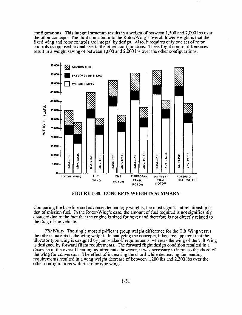
configurations.This integral structureresultsin aweightof between 1,500 and 7,000 lbs overthe other concepts. The third contributor to the Rotor/Wing's overall lower weight is that thefixed wing and rotor controls are integral by design. Also, it requires only one set of rotorcontrols as opposed to dual sets in the other configurations. These flight control differencesresult in a weight saving of between 1,000 and 2,000 lbs over the other configurations.
_.1v
I--"7"
U.I
60,000- - _] MISSION FUEl.
55,000- - I PAYLOAD/UP. ITEMS
$0,000- - D WEIGIIT EMPTY
45,000- -
40t000.- -
35,000--
%N.N.\
_TxN.\
25,000- -
Z0,000 -
15,000- -
I0,000-- _ m I
5,000- - _ - •• t:_ i
0
ROTOR/WING
_ ,,..1
,._ _ _ _; _t_ :_.
I
TILT TILT TURBOFAN
WING ROTOR TRAIL
ROTOR
FIGURE 1-38.
II
ga i_
en
PRI)PFAI'4
TRAIL
ROTOR
i
FOLDING
TILT ROTOR
CONCEPTS WEIGHTS SUMMARY
Comparing the baseline and advanced technology weights, the most significant relationship isthat of mission fuel. In the Rotor/Wing's case, the amount of fuel required is not significantlychanged due to the fact that the engine is sized for hover and therefore is not directly related tothe drag of the vehicle.
Tilt Wing- The single most significant group weight difference for the Tilt Wing versusthe other concepts is the wing weight. In analyzing the concepts, it became apparent that thetilt-rotor type wing is designed by jump-takeoff requirements, whereas the wing of the Tilt Wingis designed by forward flight requirements. The forward flight design condition resulted in adecrease in the overall bending requirements, however, it was necessary to increase the chord ofthe wing for conversion. The effect of increasing the chord while decreasing the bendingrequirements resulted in a wing weight decrease of between 1,200 Ibs and 2,300 lbs over theother configurations with tilt-rotor type wings.
1-51
Tilt Rotor- The general configuration of the tilt rotor should be considered similar to theV-22 Osprey with the following changes; there is no requirement for wing folding, there is noloading ramp, the fuselage is pressurized, and the drive system allows for a two-speed rotorgearbox.
Trail-Rotor Convertiplane- There are three weight groups which distinguish theTrail-Rotor Convertiplane from some of the other configurations. First, the main rotor blades areconsidered to be soft-in-plane or more flexible which results in a weight savings. Second, theTrail-Rotor Convertiplane requires a blade folding sy.stem which increase the weight of the huband hinge group. Third, it requires a convertible engine which increases both the engineinstallation weight as well as the amount of mission fuel required.
Propfan Trail Rotor Convertiplane- The only difference between the Propfanconfiguration and the baseline Trail Rotor Convertiplane is the addition of two propellermodules. The increased weight of adding the propeller modules is partially offset by a decreasein mission fuel required, however, the combination resulted in an overall increase in gross
weight.
Folding Tilt Rotor- There are two weight groups which make the Folding Tilt Rotor differentfrom some of the other concepts. First, it reqmres a blade folding system which increases theweight of the hub and hinge group. Second, it requires a convertible engine which increases boththe engine installation weight as well as the amount of mission fuel required.
Conclusions Drawn From Trade Studies
The application of advanced technology improves all concepts by every measure. High-speedrotorcraft concepts require large propulsion systems to achieve 450 KTAS cruise. The propulsionsystem represents the technology area which shows the greatest potential for improving concepteffectiveness. By reducing fuel required for the mission, gross weight and empty weightdecrease, while economy of the concepts increases. Reduction of engine weight contributes to alower weight empty as well. Beyond the reduction in fuel and engine weight, secondary effectscascade to result in even greater reductions. As the gross weight decreases, power required alsodecreases, which results in additional engine and drive train weight reductions.
Improved aerodynamics impacts concepts using proprotors as propulsive devices more thanothers. Maintaining high propulsive efficiencies at high speeds, significantly improves theeffectiveness of these concepts. The ability to achieve this with a rotor also designed for hover
may be challenging. Aerodynamics primarily affects fuel consumption, with a secondarystructural weight reduction as previously described.
The trade between thick wings for stiffness and sweep for delaying drag divergence represents an
extremely important technology assessment. The ability of some of the concepts to fly at moreefficient, higher altitudes was severely limited by allowable sweep. Significant gains inaerodynamics must be made to reduce the sweep requirement.
A final conclusion results from the relatively low technology risk presented by the Rotor/Wing,
It represents the cleanest configuration from a drag standpoint, so aerodynamic improvementsmay not affect it to the degree of other configurations. Power reduction impacts the concept lessthan the others because it does not require a drive system. For this reason, the Rotor/Wing
1-52

appearslessaffectedoverall bytechnologyimprovements.While notrequiringadvancedtechnologyengines,improvementsin thecruiseefficiencyusinghigherbypassratio enginesmaysignificantlyimproveits effectiveness.Currentpropulsionconceptsincorporatelow bypassratioengines.
1-53

RECOMMENDATION OF CONCEPTS FOR TASK 2
Concept Ranking
Eight parameters comprise the evaluation matrix for ranking the sized concepts. Measures ofeffectiveness and individual vehicle attributes make up the items to be evaluated. Figure 1-39
depicts the ranking matrix.
CONCEPT
CATEGORY
VELOCITY LINfl'T
(0.83)
DISK LOADING(1.66)
PAYLOADDELIVERYEFFICIENCY (3.33)
ROTOR/WING
8.35
20
FOLDINGTILT ROTOR
4.15
10
13.2
TURBOFANTRAILROTOR
4.15
lO
13.2
PROPFAN TILTTRAIL ROTOR
3.32
10
20
ROTOR
1.66
10
16.5
TILT WING
2.49
8.35
16.5
PRODUCTIVITY 20 9.9 9.9 6.6 13.2 16.5(3.33)
PAYLOAD/RANGE 10 3.32 5 10 8.3 6.64(3.33)
GROSS WEIGHT 20 6.6 9.9 3.3 13.2 16.5(3.33)
SPECIFIC RANGE 10 1.67 3.34 8.35 5 6.68(1.66)
RISK 3.32 1.66 1.66 1.66 4.98 4.15(0.83)
TOTAL 96.67 50.51 57.15 63.22 72.84 77.84
RANKING 1 6 5 4 3
FIGURE 1-39. CONCEPT SELECTION MATRIX FOR TASK 2
2
In some cases, subjective evaluations determined rankings. For instance, since 450 KTAS sizedall concepts, the potential limiting speed of each candidate was based on inherent conceptlimitations and then relative drag values. So, the rotor-driven concepts in cruise naturally have alower speed limitation than the folded rotor concepts. Next, the folded rotor concepts, due tohigher drag, possess lower speed limits than the Rotor/Wing for equivalent available cruisepower. Risk represents the other subjective evaluation area. Evidence of previous successfuldevelopmental work indicates a level of knowledge and risk associated with a concept. Flightdemonstrations, wind tunnel testing to prove feasibility, and lack of required technologiescontributed to rankings in this area. An example of lack of required technology, is the
convertible engine required for the Folding. Tilt Rotor and Trail Rotor. Compared to propulsionsystems of other concepts, very little experaence exists. General Electric demonstratedfeasibility, but no program currently exists to develop and produce the engine. Without it,
1-54

folding rotor conceptscannotfly unlessapropelleris usedasapropulsor.While viable,itrestrictstheattractivenessof folding concepts- their speedcapability. TheRotor/Wing'sriskranksaheadof thefolding rotorconceptduesolely to theavailabilityof anengine.
Comparativerankingsbasedonquantitativeresultsof thetradestudiescomprisetheotherevaluatedareas.Eachconceptwasrankedaccordingto "goodness",allowing ties. Theevaluationparameterswereweightedaccordingto importanceashigh,medium,or low.Multipliers (in parentheses)accountfor therelativeweight. A conceptrankedbestin agivencategoryreceived6 points. Thatvaluewasthenmultipliedby theweightingfactor; theresultdenotesthefinal score.Onehundredpointsrepresentsthemaximumpossiblescore.
Theoverall resultsof therankingshowtheconceptsfinishing in thefollowing order:
1. Rotor/Wing2. Tilt Wing3. Tilt Rotor4. Trail Rotorw/UDF5. Trail Rotor6. FoldingTilt Rotor
Selection for Task 2
MDHC recommended advancing the Rotor/Wing and the Tilt Wing for more detailed study inTask 2.
The Rotor/Wing clearly demonstrates capabilities and concept effectiveness beyond any otherconcept studied. This results from a cleaner cruise configuration and lighter empty weight. Dueto the amount of initial concept exploration in the mid 60's, including whirl stand, wind tunnel,dynamic model conversion, and transonic tests, much is known about this configuration. TheXH-17 and XV-9A technology demonstrators incorporated reaction drive rotors in their designs.The lack of required engine technology development, such as a convertible engine, makes thedevelopment risk less than any one of the folding concepts. However, desired enginedevelopment increases the utility and effectiveness of the concept. As with each of the conceptsstudies, the Rotor/Wing represents a level of risk associated with it and requires solutions toproblems prior to production. As a vehicle to study technology needs, it provides a unique set oftechnologies not inherent to other concepts. Based on results of this study, the Rotor/Wingappears as a moderate risk concept with high payoff in effectiveness.
The Tilt Wing represents a proven concept. While essentially comparable to the Tilt Rotor inranking, it potentially offers a lighter weight solution and eliminates the hover downloadcharacteristic of tilting rotor concepts. Eliminating the pitch fan using rotors instead ofpropellers may significantly increase handling qualities and agility in the low-speed regime. Itoffers a different concept than the Rotor/Wing and one which has not benefited from advanceddevelopment, as has the Tilt Rotor.
1-55


SECTION II
TECIINOLOGY EVALUATION FOR SELECTED CONCEPTS


INTRODUCTION
The results of the initial concept assessment of Task 1 indicated that the Rotor/Wing andthe Tilt Wing offered the best potential for the given generic mission. Folding rotorconcepts incurred additional weight and drag penalties in both flight regimes due tocarrying two discrete propulsion systems. The chosen concepts provided the opportunityto assess a wide range of technologies required of these widely differing concepts. Themissions assigned to the concepts included the military transport mission for the TiltWing and the ground attack mission for the Rotor/Wing. The choice of these missionsimplies suitability of the concepts for the mission. The scope of the contract prevented adetailed analysis to determine the mission best suited for each concept and therefore,mission selection required the use of engineering judgement. A more stringent missionwould typically illuminate the technologies that may otherwise go unnoticed. Themilitary missions require more time in helicopter/low speed mode than the civil missionsand therefore represent a stringent mix of rotary and fixed wing requirements.
The Task 2 study highlighted the lack of analysis tools available to assess various aspectsof high-speed rotorcraft configurations due to their hybrid nature. It also demonstratedlack of data bases available to correlate data from earlier similar concept model or flight
tests, although much is available in a narrow design range for both of these concepts.Previous designs did not require the high-speed capability which seriously impact someelements of the configurations.
The approach to identifying technology needs examined more the impact of achieving acapability level, rather than identifying a technique to achieve it. For example, theimpact of improving the high-lift capability of a wing assesses the improvement inperformance of the Tilt Wing, and stresses the criticality of that technology. The meansto achieve that improvement remains unimportant at this stage of study. Assessing thepayoff to concept effectiveness does require estimation of the level of improvementpossible, so techniques to reach these new levels are implied, but not specified.
2-1
CONCEPT SIZING
Design Criteria
Wing Loading and Disk Loading- Three basic flight regimes govern V/STOLaircraft sizing: hover, forward flight and conversion. Good hover performance requires alow disk loading and a high wing loading (for low hover download). Good Cruiseperformance requires a high disk loading and a high wing loading. Good conversion andreconversion performance, depending on the configuration, usually requires a low wingloading, and in the case of the Tilt Wing, a high disk loading. These criteria are usuallyaccompanied by an operational constraint which limits hover disk loading.
The only limiting criterion placed on disk loading is a maximum allowable disk loadingof 40 psf. These values have been determined to create the maximum allowableoverturning moment due to rotor outwash for a tilt rotor aircraft: While these values areused for this study, they may be optimistic depending on configuration and locationaround the aircraft. Due to the sensitivity of the constraint on the size of the vehicles,additional investigation must be accomplished to more fully define the allowabledownwash limits in terms of disk loading. Conversion places an upper limit on wingloading. The conversion wing loading values for the Tilt Wing and Rotor/Wing are 90 psfand 65 psf respectively.
Aircraft Structure- Good aerodynamic performance calls for thin wing sections.However, structural criteria which determine aeroelastic properties and load-bearingcapabilities limit minimum wing thickness. The load-bearing criteria used on the twoaircraft differ in the missions each aircraft flies. The airplane-mode load factors, whichsize each aircraft, are 2.5 and 3.5 for the Tilt Wing and Rotor/Wing, respectively. Thetwo designs satisfy the specifications in MIL-A-8860 through 8864 and 8870 AirplaneStrength and Rigidity.
Mission- The specific missions influence the configuration design more than anyother requirement. The military transport mission was applied to the Tilt Wing, and theground attack mission was applied to the Rotor/Wing. The following descriptions definethe two missions.
Military Transport Mission:
* Entire mission at ISA + 15° C.
* i minute hover OGE and takeoff at sea level at design gross weight.* Fly to conversion mode speed and convert to cruise configuration in 1 g flight.* Climb to cruise altitude to minimize time enroute. Full credit for range.* Dash at 450 kts. To a radius of 350 n.mi.
* Descend at Vd_vewith no credit for range.* Convert to hover mode in 1 g flight.* 15 minute hover OGE at sea level.
* 30 minute loiter at Ve,,_ in best configuration for loiter.* Convert and climb to altitude for best range taking credit for range.* Cruise at V99 max NMPP 350 n.mi. To home base.
2-2

* Descendwith nocredit for range.* 1minutehoverOGEat sealevel.* Landwith 10%fuel reserve.
GroundAttackMission:
* EntireMissionat4000ft., 95°F.* 1minutehoverOGEandtakeoff.* Fly to conversionspeedandconvertto cruiseat 1g.* Cruiseout 150n. mi. at V._,.* Dash50n. mi. at 400kts.TAS. andatIRP.* Convertto hovermode.* NOE maneuverincluding 15minutehoverOGEand 15minutesat40kts.* Attack targetsat IRPfor 5 minuteswithoutexpenditureof externalpayload.* Convertto cruisemode.
Table2-1depictstheamountof mission-dependentweightasspecifiedby thestatementof work (all valuesarein lbs.):
Weight in lbs
Weight Tilt Wing Rotor/Wing
PayloadAirframe Equipment
(not including controls)Mission Equipment
(Core avionics & defensive;tactical incl. fire control
and visionics)Armor
Mission KitCrew
60003O00
1500
4001000470
3000200
2000
400500470
TABLE 2-1. MISSION WEIGHT REQUIREMENTS
Control power requirements in hover conform to the Level 1 guidelines of MIL-F-83300(Flying Qualities of Piloted V/STOL Aircraft). Both the Tilt Wing and Rotor/Wingpossess a 1.25g capability in hover (including download). The handling qualities areaccounted for conceptually by looking at previous Tilt Wing aircraft and dynamicallyscaled wind tunnel tests of the Rotor/Wing concept. This allows consideration ofadequate handling qualities through the use of aircraft geometries similar to those ofprevious designs. Tail volume coefficients based on the CL-84, XC-142, for example,
2-3
will beusedto sizetheempennageof theTilt Wing. Thisapproachprovidesaroughideaat whatthehandlingqualitieswill be,basedon thoseof theaircraftpreviouslyflown andtested.
Assumptions
In order to ensure accurate designs, there are certain design boundaries within which theconfigurations must operate in that are not described in the statement of work designcriteria. The following represents a discussion and justification of the assumptions madewith each configuration.
Tilt Wing- Three successful Tilt Wing designs provided information useful in thedesign of a high-speed Tilt Wing. This information forms the basis of assumptions madein the current design effort.
Wing: Conversion wing loading is the single most important factor in the TiltWing sizing process. The results of a conversion study indicate that a wing loading todisk loading ratio of 2.57 provides adequate conversion capabilities for a wing withfull-span double-slotted fowler flaps and leading edge slats.
Wing thickness to chord (tic) ratio is another large factor driving Tilt Wing sizing. Awing t/c ratio of 18% was chosen, after a simple analysis, to satisfy the structural andaeroelastic criteria stated above, while maintaining fairly good cruise efficiency. Thischoice is supported by the XC-142 and the CL-84 Tilt Wing designs which used 18%thick wings.
Drag: There were several assumptions made affecting aircraft performance, themost significant having to do with the calculation of aircraft drag. A standard dragbuildup was completed on all of the aircraft components, including sponsons, using skinfriction coefficients based on Reynold's number and roughness. Additional fuselage dragdue to aft fuselage upsweep was computed using an empirical method developed byDouglas Aircraft. The wing airfoil section used represents a state-of-the-art supercriticalsection developed under the Navy Medium-Speed V/STOL Program. Wind Tunnel Testresults provided the necessary drag data) 5 The sum of all component drag was thenincremented by 10% to account for interference and protuberance drag.
VASCOMPII _9calculated Oswald efficiency factor for the Tilt Wing. Analysis from
Douglas Aircraft's DACPROP then determined the decrement in Oswald efficiencyfactor due to up-at-wingtip propeller rotation.
Propulsion: The assumptions regarding propulsion were selected usingwell-documented production codes from both Allison (T406 engine) and DouglasAircraft (prop/rotor performance). Allison's customer T406 engine deck was reduced toVASCOMP II format, and assumed scalable within small ratios. The assumption ofscalability appeared valid after final sizing showed the required engine horsepower to be6411 HP, which is very close to the 6000 HP T406 deck which was used to generate theVASCOMP II engine data. Douglas provided rotor performance in hover and cruisewhich were implemented in the form of Figure of Merit (0.857 SL Std.) and cruiseefficiency (0.790 15,000 ft ISA + 15°). The code used to generate these efficiencies has
2-4

beenvalidatedagainstV-22prop/rotorperformance,andshowsgoodagreement.Therotor wassizedto a sealevel ISA + 15° C Ca-/_of .149whichallows for a 1.2g hovermaneuvermargin.
A tip speedof 750fps waschosenatthestartof theTaskII study,in lieuof adetailedprop/rotoranalysis.Subsequentanalysesshowthatatip speedof 810fpsmayincreasecruiseefficiencyand/orincreasehovermaneuveringcapabilityby reducingrotor solidityfor thesameCx/_. Futurehigh-speedTilt Wing studieswill requiretradestudiesbetweenhoverefficiency,hovermaneuverabilityandcruiseefficiency.
Empennage:Theempennagewassizedusingexistingtail volumecoefficients.Initially, a staticstability analysissizedtheempennage,but resultsfrom thatanalysisproducedtail volumecoefficientsthatweremuchsmallerthanpreviouslydesignedTiltWings. After someadditionalresearch,it wasfoundthatlow speedandtransitionalflightsizestheempennage.Thus,thehighesttail volumecoefficientstypical of theCL-84 andtheXC-142wereused.Theyare I. 10for thehorizontalstabilizerand0.12for theverticalstabilizer.ThehorizontalstabilizerusesaNACA 0015airfoil with anaspectratio of 4.0,andtheverticalstabilizerusesaNACA 0012airfoil with anaspectratioof 1.5.
Rotor�Wing- The assumptions made in the design of the Rotor/Wing are supportedby extensive studies completed from 1963 to 1969 by Hughes Tool Company on theRotor/Wing concept. Detailed wind tunnel studies were used to aid in performanceestimation along with dynamically-scaled wind tunnel investigations which completed afull transition from helicopter to fixed-wing flight. Analysis also relied on extensive dataand methodology relating to reaction drive rotor systems, derived from the XV-9A andthe XH-17 research helicopters. Both of these aircraft flew reaction drive rotor systemssimilar to the Rotor/Wing's in the 1960's.
Wing: The Rotor/Wing configuration has two constraints which determine wingsize, the first and more critical being conversion wing loading. Since the centerbodycarries all of the lift during conversion, its area must be large enough to carry theRotor/Wing at 170 kts. This ensures that the rotor carries no load while it stops. Windtunnel tests of the triangular centerbody demonstrated a lift-curve slope of 0.04/deg.Constraining the attitude of the aircraft to 15 deg. nose-up, further defines the conversionwing loading.
The second factor driving wing loading is rotor blade size. Since the Rotor/Wing musthover, there has to be enough blade area to keep the rotor unstalled. This area decreasesthe cruise wing loading because two blades and the centerbody comprise the wing.
The root cutout due to the large centerbody makes the ratio of CT/CYunusable as an
indicator of rotor stall. Because of this, a simple strip analysis was used to estimateaverage CRas a function of rotor solidity and root cutout. LSAF 2° confirms good hoverperformance of this rotor, while CAMRAD JA 2_confirms adequate helicopter and
autogyro performance.
Drag: The drag buildup for the Rotor/Wing is essentially the same as the TiltWing. Extensive data from the 1960's Rotor/Wing wind tunnel tests for both autogyroand fixed-wing flight provided comparative values. The current design achieves L/Dratios approximately 10% greater than the 1960's investigations. The smaller fuselage
2-5
andthelackof abladefairing on topof thefront partof thefuselageaccountfor thisdifference. TheL/D ratiosfor autogyromodeobtainedwith CAMRAD JA analysiscorrelatewell with wind tunneltests. A 20%thick elliptical airfoil wasusedfor thewingsectionsat theroot. Thewing taperandgasductingdeterminehow thewing thicknessisreducedalongthespan.
Oswaldefficiency factorobtainedfrom the1960'swind tunneltestshelpdetermineinduceddrag. Sincethecombinationof wing aspectratio andOswaldefficiencyfactordeterminesdrag,carefulconsiderationwastakentoensurethataspectratio,specificallywing area,is definedthesamewayasin the 1960'sanalyses.A valueof 0.75for Oswaldefficiencyfactorwasassumed.
Propulsion:TheRotor/Wingusesacommonpropulsionsystemin all flightmodes.For this study,thePratt& WhitneySTF842turbofanengineis used.Satisfyingthegasgeneratorrequirementin hover,andthethrusterrolein autogyromodeandcruisemeantselectingalow by-passratio. Sincetheseenginesareadvancedtechnologyengines,thedatawasconvertedto currenttechnologyusingtheIHPTETdesigncriteriaused in the development engines.
Relations developed in the XV-9A and XH-17 programs determine the total pressurelosses from the engine exit to the rotor tip. These losses, coupled with the rotor bladeelement analysis dictate the engine size.
Empennage: The vertical tail for the Rotor/Wing is sized by the tail volumecoefficient determined from the dynamic model tests in the 1960's. The value for thiscoefficient is 0.137.
The horizontal tail volume coefficient determined by the 1960's tests could not be used,however, because the present design stops the wing with two blades in forward. Thiscreates a forward-swept wing which moves the aerodynamic center of the wing forward.This forward location sizes the horizontal stabilizer for static stability, making it largerthan normal.
This dictates a larger horizontal tail which appears to be a reasonable trade off because ofseveral factors. The horizontal stabilizer needs to be slightly oversized for roll control infixed-wing flight. Also, stopping the rotor forward allows for a shorter fuselage withoutthe need for a blade fairing above the canopy, thus reducing drag. This brings the pilotcloser to the rotor shaft improving sensed handling qualities in helicopter and autogyro
flight modes.
Weight Estimation Methodology: The baseline weight estimation methodologyused for Task 2 is identical to that of Task 1. A discussion of this methodology waspreviously described in Section I.
Payload, fixed equipment and operating items weights were specified in the proposal. InTask 2 these weight groups varied between configurations due to the different missionscenarios. The Tilt Wing configuration was sized using the weights specified for themilitary transport mission. The Rotor/Wing configuration was sized using the weightsspecified for the military attack mission.
2-6
A trade-offstudywasperformedto evaluatetheweightdifferencebetweentwoengineswith cross-shaftingversusfourengines(twoperrotor) withoutcross-shafting.Theanalysisconsideredtheweightof theengineinstallation,gearboxes,anddrive shafts. Inthisparticularcase,thereappearsto besomedegreeof weightsavingsin goingto anon-cross-shaftedconfiguration.Due to alackof detailsresultingfrom thescopeof thisstudy,thebestestimateof weightsavingscanonly begeneralizedasa rangebetween500and 1000pounds.
Due to theuniquedrive systemconfigurationusedin theTilt Wing concept,anothermeanswasusedto checkout thesensitivityof thedrive systemweightestimationmethodology. Sufficientdatawasavailablefrom thedrive systemschematicdrawing,shownin Figure2-26,to allowanoff-line weightanalysison aperitem basis.Comparisonof theperitemweightestimateto theparametricresultedin only a slightdifference(+5%) in thetotaldrive systemweight. Thiscomparisonhelpedto validatethesensitivityandimprovethelevelof userconfidencein thedrive systemweightestimationmethodology.
Sizing
The sizingprocessfor both theTilt Wing andtheRotor/Wingwasa highly iterativeprocess.Evenwith theassumptionsmadeabove,manyoff-line iterationsoneachdesignensuredreachingtheoptimumdesignfor eachmission.VASCOMPII (V/STOL AircraftSizing and Computer Program) sized the Tilt Wing using cruise propulsive efficienciesprovided from Douglas Aircraft Company (DAC).
A reaction drive rotor code developed by MDHC sized the Rotor/Wing. This codecombines reaction drive rotor analyses developed for the XV-9A and XH-17 programs,current MDHC weight methodology, a blade element rotor analysis, and the groundattack mission.
Tilt Wing- Initially, the entire military transport mission segments were inputalong with the assumptions stated above.
The aircraft cruises at optimum altitude. Cruise efficiency, determined by wing drag andpropeller performance, depends on the cruise altitude. For this reason initial estimates ofI0,000 ft for cruise altitude, and a wing aspect ratio of 8 were chosen, based on resultsfrom Task 1. This initial assumption provided DAC with the necessary informationneeded for the 'first cut' prop/rotor design.
Additional sizing criteria were used to size the Tilt Wing as follows:
1. The transmission highest power requirement sized the transmission (climb withlow tip speed).
2. Engine sizing ensured that the aircraft could hover with one engine out (bothrotors still powered) using a 125% contingency factor.
3. Inboard-tip-down propeller rotation decremented Oswald efficiency factor by0.2.
2-7

4. Flight Reynoldsnumber,alongwith anincompressiblewing airfoil lift anddragtable,determinewing profile drag.
5. Testsat theBoeingTransonicWindTunnelin Seattleprovidedcompressibilitydragcorrectiontables.
6. VASCOMPII allowedadditionalsizingfor othermission-dependentcriteria,suchascrewaccommodations,etc.
Missioncriteria,assumptions,andadditionalsizingconstraints,with anassumedcruisealtitude,completethesizingmatrix. Thedesignpointliesin theunconstrainedregion.
90
85
IXI 80-J
OOO 75
.Eo_ 7o
to 65to
o
60e.-
65
50
45
Max Rotor Radius
13 W/S = 80 pif Q (Rotor lit Wingtip)
Hover Disk" . Conversion Limit Loading Umit
'_ W/S - 90 psf '-'--......_ _ Design Point
°/\I
15 20 25 30 36 40 45Disk Loading (PSF)
FIGURE 2-1. TILT WING PARAMETRIC SIZING MATRIX
Figure 2-1 shows the results of the sizing exercise. The plot shows design gross weight asa function of disk loading, for five different wing loadings. A Tilt Wing reconversion
study provided a wing loading constraint for a given disk loading: Instead of using afixed chord to diameter ratio as in Task 1, a matrix of points was investigated, varying
several parameters. A concurrent conversion sensitivity study determined the conversionboundary on the sizing matrix. This constraint ensures reconversion with at least 8degrees descent angle at all airspeeds. Two additional boundaries appear in this figure.The first, a maximum rotor radius boundary, places the rotor hub at the wing tip withrotor-fuselage clearance of one foot. Increasing the wing area with the same disk loadingresults in a portion of the wing outside the rotor slipstream: an unacceptableconfiguration for a Tilt Wing. The second is based on the maximum disk loadingboundary determined by Wernicke s to result in overturning moments in ground effect.
2-8
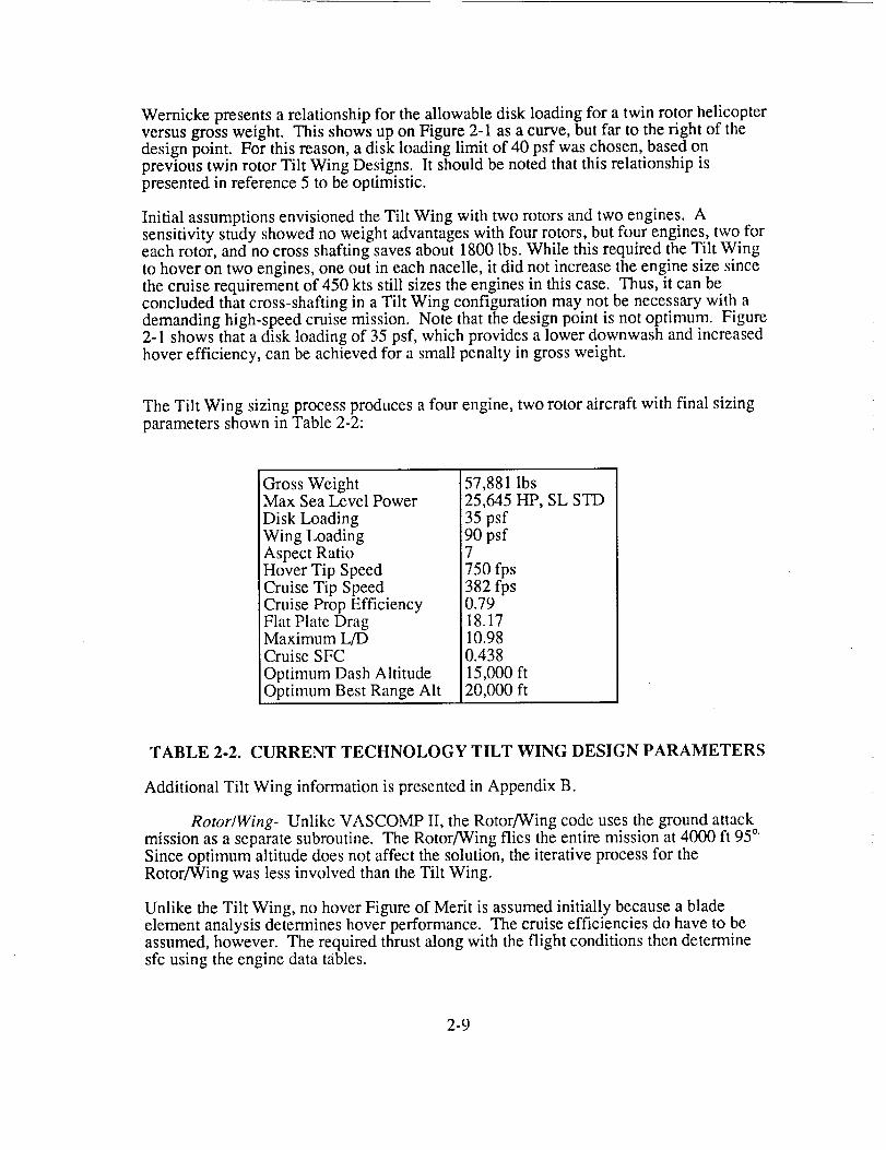
Wernickepresentsarelationshipfor theallowabledisk loadingfor atwin rotor helicopterversusgrossweight. ThisshowsuponFigure2-1asacurve,but far to theright of thedesignpoint. For thisreason,adisk loadinglimit of 40psf waschosen,basedonprevioustwin rotorTilt Wing Designs.It shouldbenotedthatthisrelationshipispresentedin reference5 to beoptimistic.
Initial assumptionsenvisionedtheTilt Wing with two rotorsandtwo engines.Asensitivitystudyshowednoweightadvantageswith four rotors,but four engines,twoforeachrotor,andnocrossshaftingsavesabout1800lbs.While thisrequiredtheTilt Wingto hoveron two engines,oneout in eachnacelle,it did not increasetheenginesizesincethecruiserequirementof 450ktsstill sizestheenginesin thiscase.Thus,it canbeconcludedthatcross-shaftingin a Tilt Wing configurationmay.notbenecessarywith ademandinghigh-speedcruisemission. Note thatthedesignpoint is notoptimum. Figure2-1showsthat adisk loadingof 35psf,which providesalowerdownwashandincreasedhoverefficiency, canbeachievedfor asmallpenaltyin grossweight.
TheTilt Wing sizingprocessproducesafour engine,two rotor aircraftwith final sizingparametersshownin Table2-2:
GrossWeightMax SeaLevel PowerDisk LoadingWingLoadingAspect RatioHover Tip SpeedCruise Tip SpeedCruise Prop EfficiencyFlat Plate DragMaximum L/DCruise SFC
Optimum Dash AltitudeOptimum Best Range Alt
57,881 Ibs25,645 HP, SL STD
35 psf90 psf7
750 fps382 fps0.7918.1710.980.438
15,000 ft20,000 ft
TABLE 2-2. CURRENT TECHNOLOGY TILT WING DESIGN PARAMETERS
Additional Tilt Wing information is presented in Appendix B.
Rotor�Wing- Unlike VASCOMP II, the Rotor/Wing code uses the ground attackmission as a separate subroutine. The Rotor/Wing flies the entire mission at 4000 ft 95 °.
Since optimum altitude does not affect the solution, the iterative process for theRotor/Wing was less involved than the Tilt Wing.
Unlike the Tilt Wing, no hover Figure of Merit is assumed initially because a bladeelement analysis determines hover performance. The cruise efficiencies do have to beassumed, however. The required thrust along with the flight conditions then determinesfc using the engine data tables.
2-9

The Rotor/Wing uses many of the same sizing constraints as the Tilt Wing:
1. There are no transmission sizing requirements.
2. Engine sizing ensured that the aircraft could hover with one engine out using a125% contingency factor.
3. All wing drag comes from skin friction coefficients and form factors. A dragcoefficient increment of 0.023 is added during cruise at 400 kts for compressibilitydrag.
4. Various other provisions within the code account for mission-dependent criteriasuch as crew accommodations, etc.
35
A 33
O,r,-
31l-
29e-
_D
C) 27
[ _ is the ratio of Canterbody Radius
to Rotor RadiusLimiting Constraints:
Conversion Wing Loading < 65
Rotor Radius < 28
Disk LoadingBoundary
\,D( - 0 50
Conversion _-_'1_
Wing Loading _ _
Boundary
Rotor Radius
Boundary _
_t
30
Design Point/
25 2040 3_6 15
Radius (FT)
FIGURE 2-2. ROTOR/WING PAMETRIC SIZING MATRIX
For the Rotor/Wing, power required does not equal power available from the engines dueto the relative inefficiencies of the reaction drive system. This inefficiency occurs due tofriction and heat loses fond in the duct system which tends to require more energy fromthe gas generator than its shaft driven counter part. The engine is sized, accounting forthese losses, based on data available from the XV-9A hot cycle helicopter program.Losses from the engine exit to the blade duct are assumed to be the same as the XV-9A.The blade duct is subdivided into three sections to allow for geometry variations and thelosses for each section are computed based on the flow information at the beginning ofeach section. The tip nozzle efficiency is also assumed similar to the XV-9A. The exitMach number of the flow is constrained to below sonic conditions and mass flow then
2-10
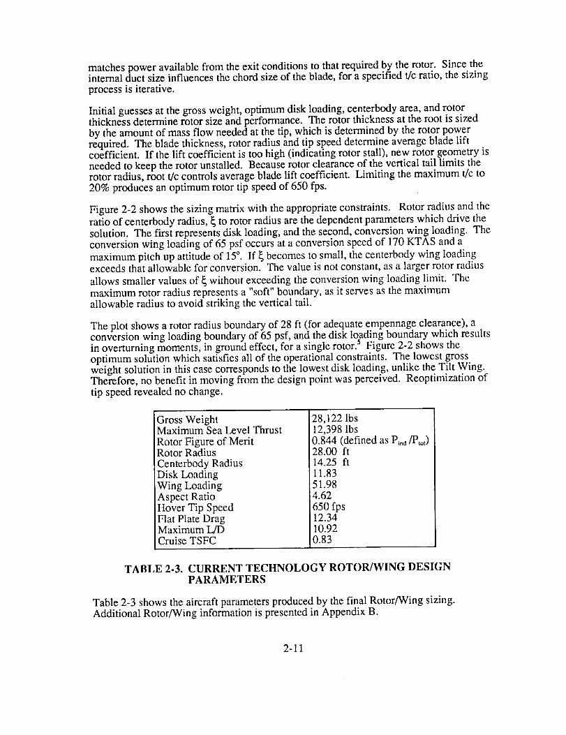
matches power available from the exit conditions to that required by the rotor. Since theinternal duct size influences the chord size of the blade, for a specified t/c ratio, the sizingprocess is iterative.
Initial guesses at the gross weight, optimum disk loading, centerbody area, and rotorthickness determine rotor size and performance. The rotor thickness at the root is sizedby the amount of mass flow needed at the tip, which is determined by the rotor powerrequired. The blade thickness, rotor radius and tip speed determine average blade liftcoefficient. If the lift coefficient is too high (indicating rotor stall), new rotor geometry isneeded to keep the rotor unstalled. Because rotor clearance of the vertical tail limits therotor radius, root t/c controls average blade lift coefficient. Limiting the maximum t/c to20% produces an optimum rotor tip speed of 650 fps.
Figure 2-2 shows the sizing matrix with the appropriate constraints. Rotor radius and the
ratio of centerbody radius, _ to rotor radius are the dependent parameters which drive the
solution. The first represents disk loading, and the second, conversion wing loading. Theconversion wing loading of 65 psf occurs at a conversion speed of 170 KTAS and a
maximum pitch up attitude of 15°. If _ becomes to small, the centerbody wing loadingexceeds that allowable for conversion. The value is not constant, as a larger rotor radius
allows smaller values of _ without exceeding the conversion wing loading limit. The
maximum rotor radius represents a "soft" boundary, as it serves as the maximumallowable radius to avoid striking the vertical tail.
The plot shows a rotor radius boundary of 28 ft (for adequate empennage clearance), aconversion wing loading boundary of 65 psf, and the disk loading boundary which resultsin overturning moments, in ground effect, for a single rotor. _ Figure 2-2 shows the
optimum solution which satisfies all of the operational constraints. The lowest grossweight solution in this case corresponds to the lowest disk loading, unlike the Tilt Wing.Therefore, no benefit in moving from the design point was perceived. Reoptimization oftip speed revealed no change.
Gross WeightMaximum Sea Level Thrust
Rotor Figure of MeritRotor Radius
Centerbody RadiusDisk LoadingWing LoadingAspect Ratio
Hover Tip SpeedFlat Plate DragMaximum L/DCruise TSFC
28,122 lbs12,398 lbs0.844 (defined as Pind/Plot)
28.00 ft14.25 ft11.8351.984.62
650 fps12.3410.920.83
TABLE 2-3. CURRENT TECHNOLOGY ROTOR/WING DESIGNPARAMETERS
Table 2-3 shows the aircraft parameters produced by the final Rotor/Wing sizing.Additional Rotor/Wing information is presented in Appendix B.
2-11

Concept Weights Summary- A group weight breakdown in a format similar toMil-Std-1374A Part I can be found Tables 2-4 and 2-5 for the Tilt Wing and Rotor/Wing
respectively.
Weight in lbs
CURRENT XC-142A CL-84
G R O U P TILT WING %GW %GW %GW
'WINGMAIN ROTOR BLADES
M/R HUB & HINGETAIL ROTOR
HORIZONTAL TAILVERTICAL TAIL
BODY GROUPALIGHTING GEAR
NACELLES(*STRUCTURAL GROUP*)
ENGINEPROPELLER INSTL.
PROPULSION SUBSYSFUEL SYSTEM
DRIVE SYSTEM & TILTFLIGHT CONTROLS
(*SYSTEMS GROUP*)
443114792262
1010466
4594115951409
(17246)
4049
954744
67593646
(16152)
4900
7.72.63.90.01.70.87.92.82.4
(29.8)
6.6
0.81.60.7
12.93.22.9
(28.5)
7.0 7.10.0 4.01.6 1.41.3 1.2
11.7 7.16.3 6.8!
(27.7)
8.0
(27.9)
8.5
6.9
0.51.71.2
12.13.72.6
(28.7)
10.06.72.41.67.93.9
(32.5)
7.1FIXED WEIGHT
EMPTY WEIGHT 38298 66.2 64.2 68.3
PAYLOAD 6000 10.4 19.4 13.4OPERATING ITEMS 1470 2.5 2.0 3.2
FUEL 12113 20.9 14.4 15.1
GROSS WEIGHT 57881 100% 100% 100%
TABLE 2-4. TILT WING WEIGHT BREAKDOWN
To support the validity of the parametric weight analysis, and to serve as a sanity check,the structural and system group weights of the configurations were compared on apercent gross weight basis to vehicles of similar design in Table 2-4. Comparison of thecurrent Tilt Wing configuration to both the XC-142A and CL-84 resulted in significantpercent gross weight differences in the areas of the body group and drive system. Thedecrease in percent body group can be explained by the configuration geometry while theincrease in percent drive system is explainable due to the unique configuration andtwo-speed requirements. The 1960's Rotor/Wing serves as the only vehicle similar to thecurrent Rotor/Wing for comparison. Allowing for vehicle geometry differences andoverall evolution of the design, Table 2-5 shows no significant percent gross weightdifferences.
2-12
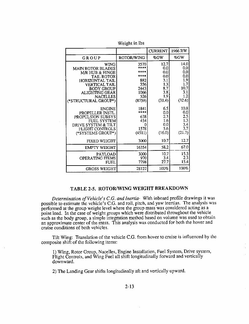
Weight in lbs
GROUP
WqNGMAIN ROTOR BLADES
M/R HUB & HINGETAIL ROTOR
HORIZONTAL TAILVERTICAL TAIL
BODY GROUPALIGHTING GEAR
NACELLES(*STRUCTURAL GROUP*)
i
ROTOR/WING
CURRENT
%GW
3570 12.7**** 0.0**** 0.0**** 0.0882 3.1356 1.3
2443 8.71066 3.8
526 1.9(8759) (31.4)
1966 RW
%GW
14.00.00.00.01.91.7
10.73.11.2
(32.6)
ENGINEPROPELLER INSTL.
PROPULSION SUBS YSFUEL SYSTEM
DRIVE SYSTEM & TILTFLIGHT CONTROLS
(*SYSTEMS GROUP*)
1841
638454
01578
(4511)
3000
6.50.02.31.60.05.6
(16.0)
10.80.02.51.33.43.7
(21.7)
FIXED WEIGHT 10.7 12.7
EMPTY WEIGHT 16354 58.2 67.0
PAYLOAD ! 3000 10.7 15.3OPERATING ITEMS 970 3.4 2.3
FUEL 7798 27.7 15.4
GROSS WEIGHT 28122 100% 100%
TABLE 2-5. ROTOR/WING WEIGHT BREAKDOWN
Determination of Vehicle's C.G. and Inertia- With inboard profile drawings it was
possible to estimate the vehicle's C.G. and roll, pitch, and yaw inertias. The analysis wasperformed at the group weight level where the group mass was considered acting as a
point load. In the case of weight groups which were distributed throughout the vehicle
such as the body group, a simple integration method based on volume was used to obtain
an approximate center of the mass. This analysis was conducted for both the hover andcruise conditions of both vehicles.
Tilt Wing: Translation of the vehicle C.G. from hover to cruise is influenced by the
composite shift of the following items:
1) Wing, Rotor Group, Nacelles, Engine Installation, Fuel System, Drive system,Flight Controls, and Wing Fuel all shift longitudinally forward and verticallydownward.
2) The Landing Gear shifts longitudinally aft and vertically upward.
2-13

Rotor/Wing: Due to its unique configuration, the translation of the vehicle C.G.from hover to cruise is influenced by only one item. The landing gear shiftslongitudinally aft and vertically upward. This minimal shift in C.G. results in inertiavalues which are almost identical for hover and cruise.
The resulting inertia values show that the roll and pitch inertias are more sensitive inhover than in cruise as shown in Table 2-6.
Configuration
Tilt Wing (Hover)Tilt Wing (Cruise)Rotor/Wing (Hover)Rotor/Wing (Cruise)
Gross
Weight(lbs)
57,88157,88128,12228,122
X Y Z
(in) (in) (in)
314.8 0.0 126.0295.6 0.0 87.7323.2 0.0 87.6324.0 0.0 88.9
Ixx Iyy Izz(Slug Feet Squared)
39,912 123,217 83,3045,235 91,237 86,0016,895 61,111 54,2156,133 60,199 54,066
TABLE 2-6. CONCEPT WEIGHTS AND INERTIAS
Aircraft Description
_LT WINGA_LITARY TRANSPORT
D_'510N _¢1055 1ff_IOHT 57,8B! t.B
POIVE'_ REOUIREO ¢-'5,645 tqP
MI_;_IOM FUEL IZ. 113 LB
PAYLOAD 6,000 LB
DI._K LOADINO 35 LB/FT t
WlNO LOAOItqO 90 LB/F1 ¢
75,-I0 =
,,'-, LI• , L
l67 -1" B'iO"
6 =
/
[_I " - 7"
FIGURE 2-3. TILT WING MILITARY TRANSPORT
2-14
Tilt Wing General Description- The Tilt Wing is configured as a militarytransport, and is shown in Figure 2-3. As in conventional tilt wings, the wing tiltsupward to a vertical position for low-speed or vertical flight; for high-speed flight thewing tilts to the standard horizontal position. However, this Tilt Wing uses rotors ratherthan propellers with beta controls; the control provided by the rotors eliminates the needfor a pitch fan.
The fuselage for the current Tilt Wing is sized for a 6x6x20 foot cargo bay. The crewstation is a two place, side-by-side type with duplicate controls for both. The missionequipment package (MEP) resides behind the right crew station, forward of the cargobay, with a volume corresponding to the 1500 pound requirement, and is stacked in a fivetier arrangement for easy access. Opposite the MEP is the flight crew access door; aft ofthe cargo bay are the cargo bay doors and ramp. The cargo bay access is configuredsimilar to a C-130 and has the same height (6 foot) as the cargo bay itself. Sponsons onthe lower fuselage house the main landing gear, while the nose landing gear is locatedbeneath the crew stations. Fuel cells are fore and aft of the main landing gear in bothsponsons. Additionally, two fuel cells are located in the wing.
The high aspect ratio wing consists of ten degrees of forward sweep inboard of the rotorpylons, and ten degrees aft sweep outboard. The wing sweep allows clearance for rotorflapping, and provides some reduction of the effective Mach number on the wing. Thehigh mounted wing has two degrees of anhedraI for enhanced maneuverability.Downturned Hoerner wingtips (similar to the A-10) aid in reducing the induced drag.Trailing edge slotted flaperons extend from seventy percent chord to the trailing edge.The wing tilts about a conversion hinge located at fifty percent chord in the local areaabove the fuselage. Hinging at fifty percent chord reduces the inertia of the tilting wing(versus hinging further aft), hence transmitting reduced loads through the hinge andconversion actuators. Additionally, a minimum of fifty percent chord is considerednecessary for the wing torque box carry-through structure. The local wing structure aft ofthe hinge and directly above the fuselage remains fixed during conversion. Twoconversion actuators are provided for redundancy.
The rotor system consists of two five-bladed rotors, with the rotor pylon underslungbelow the wing. This offset maintains the center of gravity below the center of lift inboth flight modes. Additionally, the underslung pylon aids in preserving the wing's flowattachment for improved conversion characteristics. Each rotor is powered by twoturboshaft engines, with no cross shafting between the two rotor systems. Each engineprovides all of the required power to it's rotor, should the other engine becomeinoperative (OEI).
The empennage consists of a singular vertical fin with a horizontal tail mountedconventionally. The rudder runs nearly the full span of the fin, with the horizontal tailbeing notched at the trailing edge to allow full rudder movement. Each half of thehorizontal tail has inboard and outboard ailerons.
Rotor�Wing General Description- The Rotor/Wing consists of a Warm Cyclerotor with a large triangular hub and three short-span, wide-chord blades. For verticaland low speed flight, the rotor is powered by reaction driven tip jets, fed by exhaust fromthe turbofan engines. The rotor autorotates during conversion, and stops to become aswept forward fixed wing for cruise and high-speed flight. For simplicity, use of bluntleading and trailing edge airfoils, and a feathering hinge eliminates the need for
2-15

circulationcontrol. The Rotor[Wing,showninFigure2-4, is configuredfor thegroundattackrole. Provisions were made for mounting two AGM-65 Maverick missiles on thelower outboard fuselage (one per side), and include a 20 millimeter gun internallymounted.
OE_;JOl_ GItOSS _I@HT| 2@, 122 L8
MISSION FLIEL J 7,7_ Ll)
pAYI.O,_DI 3,000 LB
HOVER D|_( LOADING, J |.B LB/FT r
MT_W flil4B LO/_D|IVOR 52.0 LB/FT"
-1,o..o-[--
_ F
-- 87"-I
60"-8
FIGURE 2-4. ROTOR/WING GROUND ATTACK AIRCRAFT
30"-0"
1
IB''IJ"
l
The forward fuselage is sized to accommodate tandem crew stations. Duplicate controlsare provided for both stations. The forward fuel cell resides behind the aft crew station;the aft fuselage houses another fuel cell to balance the fuel around the center of gravity.The mission equipment package (MEP) is located above the forward fuel cell. It isstacked in a two tier arrangement and extends to the aft fuel cell, occupying a volumecorresponding to the 2000 pound requirement. The 20 millimeter gun lies directly belowthe forward fuel cell, and the ammunition canister lies to the right of the gun. Outboardof the central fuselage are the turbofan engines (one per side). The engine supportstructure begins with the inlet just outboard of the aft crew station, and extends to theexhaust nozzle located outboard of the main landing gear. All landing gear is stowedinternally, with the nose landing gear housed below the forward crew station.
The rotor/wing is rigidly mounted on the fuselage through bearings that allow onlyrotational motion, and the blades are similarly mounted to the wing section, allowingonly pitching motion. This arrangement provides efficient support of the short, stiffblades, while avoiding the excessive weight and complexity associated with stopping aconventional rotor in flight. The center body also serves as an excellent aerodynamic
fairing for the rotor hub, thus providing the aerodynamic cleanliness required for efficient
2-16

highspeedflight. Therotor bladesareof elliptical crosssectionwith thethicknesstochordratio (t/c max= 0.2)beingtheminimumrequiredto housetherequiredreactiondrive duct.
TheWarmCycle systemthatpowerstheRotor-Wingprovidesthesimplestpossiblepropulsionsystemfor aircraftwith bothrotary-andfixed-wingoperation.Thepropulsionsystemutilizestwo standardlow bypassratio turbofanengines(bypassratio=1.0). In helicoptermode,thehighenergyexhaustgasesaredirectedby light-weightductingto therotor bladetips, whichthenpropeltherotor in thedirectionof rotation.Duringconversionandfixed-wingoperation,adivertervalveredirectstheexhaustaft,thusproviding conventionalthrust.
Theempennageconsistsof two verticalfins andastandardhorizontaltail. Eachof theverticalfins arecanted18degreesoutboard,andareequippedwith arudder.Additionally, a smallexhaustnozzleis providedin the loweraft empennageto providedirectionalcontrol.
Conversion
Conversion of any high-speed rotorcraft concept invariably generates more concern thanany other aspect of the flight regime. The specific problems differ between the Tilt Wingand the Rotor/Wing, but equal treatment is given to the conversion of each concept.
V = wcos_,, .._
(%,= FLIGHT PATH
FIGURE 2-5. VELOCITY DIAGRAM DESCRIBING TILT WINGCONVERSION
2-17
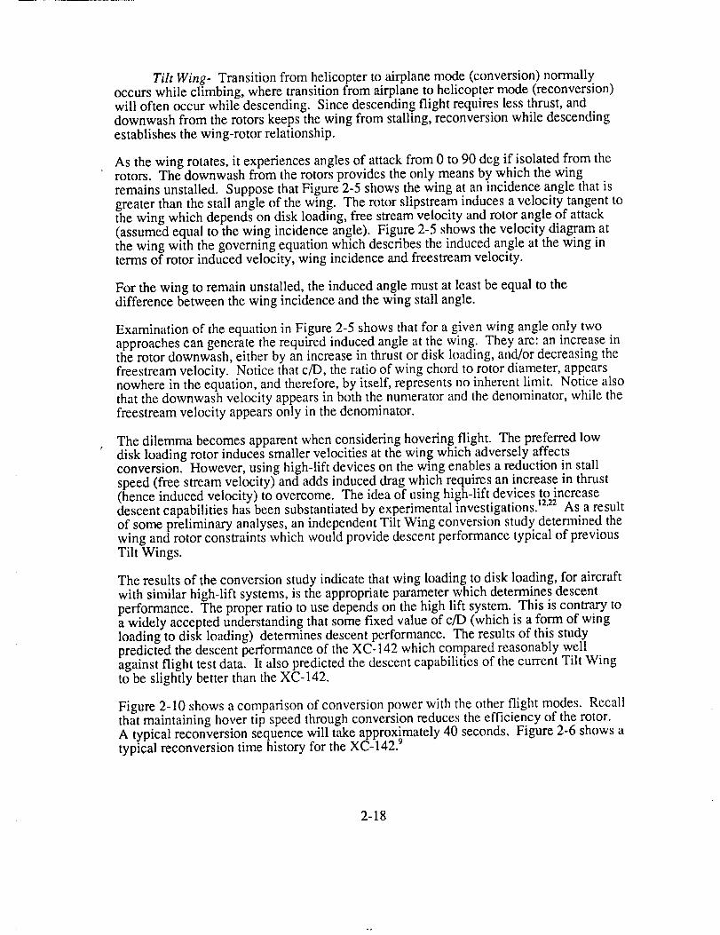
Tilt Wing- Transition from helicopter to airplane mode (conversion) normallyoccurs while climbing, where transition from airplane to helicopter mode (reconversion)will often occur while descending. Since descending flight requires less thrust, anddownwash from the rotors keeps the wing from stalling, reconversion while descendingestablishes the wing-rotor relationship.
As the wing rotates, it experiences angles of attack from 0 to 90 deg if isolated from the
rotors. The downwash from the rotors provides the only means by which the wingremains unstalled. Suppose that Figure 2-5 shows the wing at an incidence angle that isgreater than the stall angle of the wing. The rotor slipstream induces a velocity tangent tothe wing which depends on disk loading, free stream velocity and rotor angle of attack(assumed equal to the wing incidence angle). Figure 2-5 shows the velocity diagram atthe wing with the governing equation which describes the induced angle at the wing interms of rotor induced velocity, wing incidence and freestream velocity.
For the wing to remain unstalled, the induced angle must at least be equal to thedifference between the wing incidence and the wing stall angle.
Examination of the equation in Figure 2-5 shows that for a given wing angle only twoapproaches can generate the required induced angle at the wing. They are: an increase inthe rotor downwash, either by an increase in thrust or disk loading, and/or decreasing thefreestream velocity. Notice that c/I), the ratio of wing chord to rotor diameter, appearsnowhere in the equation, and therefore, by itself, represents no inherent limit. Notice alsothat the downwash velocity appears in both the numerator and the denominator, while thefreestream velocity appears only in the denominator.
The dilemma becomes apparent when considering hovering flight. The preferred lowr
disk loading rotor induces smaller velocities at the wing which adversely affectsconversion. However, using high-lift devices on the wing enables a reduction in stallspeed (free stream velocity) and adds induced drag which requires an increase in thrust(hence induced velocity) to overcome. The idea of using high-lift devices to increasedescent capabilities has been substantiated by experimental investigations) 2"22As a resultof some preliminary analyses, an independent Tilt Wing conversion study determined thewing and rotor constraints which would provide descent performance typical of previousTilt Wings.
The results of the conversion study indicate that wing loading to disk loading, for aircraftwith similar high-lift systems, is the appropriate parameter which determines descentperformance. The proper ratio to use depends on the high lift system. This is contrary toa widely accepted understanding that some fixed value of c/D (which is a form of wingloading to disk loading) determines descent performance. The results of this studypredicted the descent performance of the XC-142 which compared reasonably wellagainst flight test data. It also predicted the descent capabilities of the current Tilt Wingto be slightly better than the XC-142.
Figure 2-10 shows a comparison of conversion power with the other flight modes. Recallthat maintaining hover tip speed through conversion reduces the efficiency of the rotor.A typical reconversion sequence will take approximately 40 seconds. Figure 2-6 shows atypical reconversion time history for the XC-142. 9
2-18
ORIGINAL PAGE t_
OF POOR QUAUTY
FIGURE 2-6. XC-142 RECONVERSION TIME HISTORY
Since the Tilt Wing uses two bearingless rotors, rotor dynamics during conversion andreconversion are a concern. Whirl mode instabilities, although not analyzed, are
accounted for through wing stiffness in the weight equations. Further investigation ofrotor dynamics during conversion will analyze whirl mode instabilities. Coriolis forces (which cause the rotor to flap opposite to the direction of rotation) and the
required control inputs needed to offset them must also be investigated.
Rotor�Wing- The conversion of the Rotor/Wing requires careful consideration oftwo areas. They are centerbody lift and high advance ratios (rotor stop and start).Although the Rotor/Wing concept has never flown, extensive wind tunnel tests have
investigated conversion fully.
Data from the 1960's wind tunnel tests determined the lift and drag characteristics of
various centerbody shapes. The test results show that a triangular centerbody canmaintain a lift coefficient of 0.6 at 15 °. Although the centerbody could operate at higher
angles of attack, 15 ° represents the maximum practical aircraft attitude during conversion.The lift coefficient and the desired conversion speed of 170 kts, determine the centerbodysize.
At moderate helicopter speeds, an analysis using CAMRAD JA indicated that rotor
vibration could be a problem.
The results of an analysis using CAMRAD JA show the centerbody and rotor adequate tocarry the Rotor/Wing from 80 to 120 kts in autogyro mode. Rotor hub loads, predictedby CAMRAD JA, become excessive above 100 kts in helicopter mode.
2-19

Thegreatestconcernduringconversionis stoppingor startingtherotor in forwardflight.As theadvanceratiobecomevery large,therotorvibrationswill increase.However,ifthebladesremainunloaded,thevibrationcanbesignificantlyreducedusingcyclic pitchcontrol. In addition,thethree-bladedrotorproducesatriangularcenterbody.As thecenterbodycarrieslift duringconversion,thecenterof lift oscillatesin anellipticalpatternwith afrequencythreetimestherotor rotationalspeed.Reference8presentsseveralsuggestionsto overcomethisproblemincludingcyclic pitchcontrol,elevondeflection,andpossiblytheuseof a four-bladedconfiguration.Figure2-7showsanactualtimehistoryof arotorconversionfrom autogyroto fixed-wingmode. It shouldbenotedthatalthoughbasichigherharmoniccontrolswereused,noautomaticflightcontrolswereimplementedfor thisconversion.Furtherinvestigationwill determinethebenefitsof higherharmoniccontrol,automaticcontrols,four blades,etc.
150 RPM
f-
Nv--
L_
M.--
'i iMv_
• k'f "_ t
_F I
RUN 82-PDEtEr ERATIO_ A ]
&z,5"
A z
M
Mfl
MSll MS t
50 RPM
- - ....
,: I &
Longttudina| cyclic pitch control angle, degrees
2 per revotutLon longitudin.I _ychc p_tch angle, de,reel
Rolling moment, foot-pounds
Pitching moment, foot-pol_nds
P>lade root bending moment In the chordwile direchon
=nch-poundB
Rotor lha[t betiding moment _n two mL=tually perpendicular
directlonm, inch-pounds
N
N R
e
yawing moment, foot-pounds
Rotor ipeed, rpm
Rotoe collective pitch angle, degree=
FIGURE 2-7. WIND TUNNEL TEST SHOWING ROTOR/WING CONVERSIONFROM HELICOPTER TO AIRPLANE MODE.
Performance
Both the Tilt Wing and the Rotor/Wing demonstrate different levels of performance inhelicopter, conversion and airplane mode. Figures 2-8 and 2-9 show the flight envelopesfor the Tilt Wing and the Rotor/Wing, respectively. Several different limitationsdetermine the flight envelope on each. Figures 2-10 and 2-11 show the sea level,standard day, composite power curves for the Tilt Wing and Rotor/Wing, respectively.
2-20

40000
v
..!
<
35000
30000
25000.
20000.
15000,
10000-
5000
00
u
50 100 t50 200 250 300 350 400
Airspeed, (KTSI
FIGURE 2-8. TILT WING FLIGHT ENVELOPE.
Limit
4so 600
5OOOO
45000-
40000"
36000'
30000
15000-
1OO00-
5000-
0-0
AirplaneBoundar
Low-SpeedAutogyroBoundary
SO 1OO 160 200 250 300 360 400 450
Airspeed, (KTS)
DragDivergenceMachNumber
_-Limit
MCTThrustUmit
6OO 550
FIGURE 2-9. ROTOR/WING FLIGHT ENVELOPE
2-21

30000
25000
20000-
O
15000
10000
iT"
500O
/
Airplane /
Helicopter
o 60 1oo 15o 2 o zso 300 350 400 450 5ooTrue Airspeed (KTAS)
FIGURE 2-10. TILT WING POWER REQUIRED - ALL MODES
10000
8000
£
6000-
"_ 4000-
O"0
2000-
0
Helicopter Airplan_
Autogyro
........ I .... '1 ''%" ' .................5'o ,oo ,so =60 =_o 360 3_o 400True Airspeed (KTAS)
FIGURE 2.11. ROTOR/WING POWER REQUIRED - ALL MODES
2-22

Figures 2-8 and 2-9 show that the flight envelopes are shaped at different airspeeds by thedifferent flight regimes. The slope of the low speed boundary is smaller for theRotor/Wing than the Tilt Wing. Rotor/Wing depends only on its rotor for lift until therotors are stopped. Thus, air density limits the altitude capability of the Rotor/Wing untilthe wing can carry load. The Tilt Wing, however, begins loading its wing at the onset oftransition. Thus, the Tilt Wing's rotors can be off-loaded very quickly, improving the
altitude capability with speed, compared to the Rotor/Wing.
The power curves will be discussed in more detail later in this section. The followingsection discusses selected plots required in Task 2 which will be used to describe theperformance of each concept in each flight mode.
Tilt Wing Helicopter Mode- The Tilt Wing spends virtually no time in purehelicopter mode except for hover. Figure 2-12 shows the non-dimensional power, usingV-22 airfoils, as generated by DACPROP. Simple theory also substantiated this data.
Figure 2-13 shows hover ceiling as a function of takeoff gross weight. This figure shows
that all points are limited by rotor stall (CT/_ma_ = 0.18). Since the Tilt Wing's engines
are sized for cruise (checking the power required for hover with 2 engines inoperativeand cruise simultaneously), enough power is available to hover at all altitudes until therotor stalls.
8.0
6,0-
Q.
e-ID
4.0-
O
,22.0-
(Coefficients Based on Disk Area and Tip Speed)
0.0o.oo o'.o olo2 olo3 olo4
Thrust Coefficient, CT
FIGURE 2-12. TILT WING NON-DIMENSIONAL HOVER ROTOR
POWER REQUIRED
0,05
2-23

20OOO
0O0O0<
16000
I0000-
a'_ o ISA
C
All Points limited by Rotor Stall
• I " ' I ' ' I ' I '
40000 45000 60000 65000
GROSS WEIGHT (LBS)
BOOO36000 60000
FIGURE 2-13. TILT WING HOVER CEILING
_500(Wing Incidence 60 ° - Sea Level Standard)
1250-
I000-
_._ 750-
@OO-
25O
Max Gross Weight
o._
'Runway Lengths Reflect Distance to Clear 50 ft Obstacle)
0 ' I ; " I
66000 60000 e6oooGross Weight (LBS)
J
70000 76000
FIGURE 2-14. TILT WING STOL PERFORMANCE - WING AT 60 DEG
2-24

Additional Tilt Wing helicopter-mode performance is provided in Appendix B. It shouldbe noted that this data assumes a wing incidence angle of 90 degrees at all velocities.This is not how the Tilt Wing flies, however, so the power required at any velocitygreater than zero will be higher than expected due to the large amount of drag from thewing.
Tilt Wing Conversion Mode- Conversion represents a smooth transition fromhelicopter to fixed wing mode, with oneexception. The hover tip-speed is maintaineduntil the wing locks in place (typically 120-150 kts). This, and the added drag for gapsand seals, explains the discontinuity between the power required for conversion and
airplane power required at 150 kts as shown in Figure 2-10. Figure 2-14 shows the shorttakeoff and landing (STOL) performance of the Tilt Wing. with the wing at 60 degrees,which is essentially conversion mode. Additional conversion performance information isavailable in Appendix B.
Tilt Wing Airplane Mode- In airplane mode, drag and propulsive efficiencydetermine performance. The Tilt Wing drag breakdown is given in Table 2-7.Additionally, Figure 2-15 shows the Tilt Wing L/D at design gross weight (DGW). Thecruise performance of the rotor designed for the dash requirement at 15,000 ft. is given inFigure 2-16 for several Mach numbers.
Flat Plate Area in ft 2
WettedArea
Sponsons
° includes 1.08 sq ft
for fuselage upsweep
CI FormFactorComponent
tt
Fuselage 1377 0.00187 1.48 4.89
Wing 1318 0.00263 1.47 5.11
Horizontal Tail 461.4 0.00262 1.35 1.62
Vertical Tail 351 0.00264 1.264 1.17
Nacelles 652.8 0.00342 1.36 3.04
255 0.00225 1.206 0.69
Flat PlateArea
10% for Interference 16.52and Protuberences : 1.65
Total : 18.17
TABLE 2-7. TILT WING DRAG BREAKDOWN - AIRPLANE MODE
2-25

12-
10
O
w 8n,-
!
2
u SEA LEVEL
o 10000 FT20000 FT
,of /'"u'-u. °',o." ""-,.._.
0 .... | .... i .... I ' -' ' ' 1 ' " '" ' I .... I .... I .... I .... I ....
0 50 100 150 200 250 s00 a60 400 450 600True Airspeed (KTASl
FIGURE 2-15. TILT WING LID - AIRPLANE MODE
• I
FIGURE 2-16. TILT WING - ROTOR CRUISE PERFORMANCE
2-26

0.10
0.09
o.oe
0.06
o_0.06 -
n-o
0.04 :
_. 0.03 2
0.02 :
O.Ol-
0.00
0
o SEA LEVEL
o 10000 FT
A 20000 FT
.._..&. A- &-_"eL_A'A"A" A. A_&..
/_ ="A
.... I .... I .... I .... I .... I .... t .... ! .... ! .... i ....
EO 100 150 200 250 300 3EO 400 460 600
TrueAirspeed (KTAS)
FIGURE 2-17. TILT WING SPECIFIC RANGE
2O
"1 CargoRoor Umit
A
0 1209_ 10
'10
o e>.
0
14-
Z Zi I '
0 600 I000 1600 2000
Range,(NM)2600
FIGURE 2-18. TILT WING PAYLOAD-RANGE DIAGRAM
2-27

ft.tO
@
8
(Coeft'mients Based on Disk Area and Tip Speed)
3.0-
2.0-
1.0-
0.0 ", ..... , . .' " • ; ,o.ooo 0.006 o.olo o,ot5
Thrust Coefficient, CT
0.020
FIGURE 2-19. ROTOR/WING NON-DIMENSIONAL ROTOR HOVER
POWER REQUIRED
30000
[] ISA
A + 15"C
25000
20000
15000
o3:: .
100o0
All P
t I I ! I
15000 20000 25000 30000 35000 40000
Gross Weight (LBS)
FIGURE 2-20. ROTOR/WING HOVER CEILING
46OOO
2-28

Specificrangeandpayload-rangewhichmeasuretheTilt Wing's efficiencyarepresentedin Figures2-17and2-18.Neither of thegraphsrepresentanymissioncharacteristics.Thepayload-rangeplot representsthepayloadcapacityfor agivencruisespeed,altitudeandrange. Thespecificrangeplot showsthespecificrangevariationat DGW fordifferentairspeeds,at severaldifferentflight conditions.
Rotor�Wing Helicopter Mode- Unlike the Tilt Wing, the Rotor/Wing missionrequires about 45 minutes in hover and NOE flight. Figure 2-19 shows thenon-dimensional rotor power in hover as predicted by simple theory. Comparison of thisdata to LSAF and a blade element analysis confirmed the accuracy of this data. Thesimple analysis also provided the power curves for forward flight in helicopter mode.Figure 2-20 shows the Rotor/Wing hover ceiling at DGW for a standard and hot day.Notice again that all of the points in these curves are limited by rotor stall. Thislimitation results because of excess power due to the OEI hover requirement and due tominimizing rotor solidity in deference to cruise wing loading. Additional helicopter modeperformance is presented in Appendix B.
Rotor�Wing Conversion (Autogyro) Mode- Figure 2-11 shows a discontinuity inthe power required between autogyro and the other two modes. The angle of attackneeded to trim the Rotor/Wing in autogyro flight increases the L/D ratios from those incruise. Figure 2-21 shows a comparison of the calculated L/D ratios for the Rotor/wingto the wind tunnel obtained for a similar configuration in the 1960's. Additionalconversion mode performance is presented in Appendix B.
From CRA Computing Method
Current Rotor/Wing
O--f
00. Z 0.3 0.4 0.5 0.6 0.7 0.8
ADVANCE RATIO
FIGURE 2-21. ROTOR/WING L/D - AUTOGYRO MODE
Rotor�Wing Airplane Mode- Like the Tilt Wing, drag and propulsive efficiencylargely determine airplane mode performance for the Rotor/wing. Table 2-8 shows thedrag breakdown in airplane mode. Figure 2-22 presents cruise L/D as a function offorward speed. The maximum values agree favorably with wind tunnel test data from
2-29

similar models corrected to full scale. The engine data presented previously and inAppendix B provides engine fuel efficiency for different thrust levels and Mach numbersat several altitudes.
- Wetted3omponent Area
Fuselage
Wing
Horizontal Tall
725
835.7
410
256.3
372
Vertical Tail
Nacelles
Flal Plate Area in ft2
Cf
0.00187
0.00235
0.00251
0.00247
0.00285
Form Flat PlateFactor Area
1.5
1.7
1.45
1.43
1.51
Mission Drag Increment
10% for Interferenceand Protuberences •
2.04
4.20
1.49
0.90
1.59
1.00
11.22
1.12
Total • 12.34
TABLE 2-8. ROTOR/WING DRAG BREAKDOWN - AIRPLANE MODE
12
10
O I"
"1 4
A_A_ a Ses Level
/// .,oooo..%%%%
o so =oo tr,o 200 =so 300 sr,o 40o 45o 500True Airspeed (KTAS}
FIGURE 2-22. ROTOR/WING L/D - AIRPLANE MODE
2-30
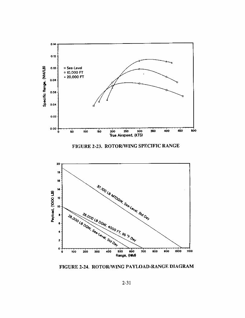
o
r-
re"
'5o
0.14
0,12-
0.10"
0.08"
o.oa,
0.04
o.o2 -
0.000
o Sea-Levelo 10,000 FT
A 20,000 FT
........ i ........... i .... i ........ i ........5'0 lOO ,_o 2_o 25o 300 3_o 400 4_o 600True Airspeed. (KTS)
FIGURE 2-23. ROTOR/WING SPECIFIC RANGE
20"
18"
1(I.
"_ % %.*"°¢
/'_ COt.
0 ! i • •
o 1oo 200 300 4o0 500 aoo 700 aoo =oo 1ooo 11ooRange, (NMI
0 12o
"_ 10
tll0 83-
a
FIGURE 2-24. ROTOR/WING PAYLOAD-RANGE DIAGRAM
2-31

The specific range and payload-range plots provide some measures of non missionspecific Rotor/Wing efficiency. The specific range and payload-range curves arepresented in Figures 2-23 and 2-24 respectively, similar to the Tilt Wing curves presentedpreviously.
In summary, low-speed flight (hover and transition) and high-speed flight bothcompromise performance. Examination of both Tilt Wing and Rotor/Wing performanceleads to a general conclusion. That is, hover and transitional flight tend toward largesurface areas, be it rotors, wing or centerbody. High-speed flight, however, tends towardsmaller surface areas because of increased dynamic pressure. The need to compromise isobvious, but the point where hover and the high-speed requirements cause the solution todiverge is not. The Task 2 performance analyses seem to indicate that, at presenttechnology, the velocity at which the Tilt Wing begins diverging is about 450 kts. TheRotor/Wing appears to possess more potential for higher speeds, but one reason for this isthat the ground attack mission flies at 400 kts for only 50 rim.
Tilt Wing Subsystem Design
Hub- The original Tilt Wing prototypes (CL-84, XC-142, & VZ-2) used variablepitch propellers that were simple to operate but offered little or no lateral or longitudinalcontrol and required additional control thrusters at the tail. Boeing proposed amonocyclic hub which could produce a pitch and/or yaw moment but was only slightlyless complex than a full cyclic hub. g
5-BLADED_RIGID HUB
F SWASHPLATE/ A--- HYDRAUL I C
__ ACTLPA TORS
FIGURE 2-25. TILT WING HUB WITH CONTROLS
Figure 2-25 shows the proposed hub which consists of a 5 bladed rigid hub with fullcyclic and collective pitch control. This ensures adequate control without the use of apitch or yaw fan. The virtual flapping axis is located at approximately 5% radius and
2-32

resultsfrom flexibility in thebladeroot. Thetotal featheringtravelof approximately60deg.Accommodatestherelativelyflat pitchathoverandnearlyfull featheringrequiredincruise.
Thenon-rotatingswashplateismountedto asphericalbearingwhich slidesona staticmast.Threehydraulicactuatorsdefinetheorientationof theswashplate.A torquelinkmountedto themastbaserestrictsrotation. Thethreeactuators,usedtogether,providebothcyclic andcollectivepitch. Simultaneousinput from all actuatorsprovidescollectivecontrol whilecyclic usesdifferential input.
Drive System- Figure 2-26 shows the proposed Tilt Wing drive system whichconsists of a 5-stage, 2-speed gearbox on each wing. Two 6411 HP engines mountedside-by-side aft of the gearbox provide the required power. Each gearbox consists ofshafting with spiral bevel sets from each engine feeding into a 4-stage planetary. Crossshafting between the rotors, which is common on similar configurations, was omitted toreduce weight and complexity. The excessive power required in cruise far exceeds thatrequired for hover and results in engines which provide over twice the power required forhover. Cross shafting was unnecessary because the aircraft can meet the hoverrequirement with only two of its four engines operating (one on each side).
OVERRUNN ] NG ---'1
CLUTCHES _SP!RAL BEVEL SETS_ ENGINE
ROTATING MAST ' PEED PLA lIES
r _FINAL REDUCT!ON
PLANETAR !ES
FIGURE 2-26. TILT WING DRIVE SYSTEM
The shafts and associated spiral bevel sets spanning the distance from the engines to themast axis were sized to carry 6411 HP MCP at 15,000 rpm. Idler gears were alsoconsidered for spanning the distance but were found to be too heavy. Analysis of themission power requirements revealed that the maximum power occurred during climb toaltitude. This power level (10650 HP/rotor) subsequently sized the planetary stages.Figure 2-27 shows the two-speed gearbox which is used to achieve two-speed operation.The two planetaries' reduction ratios provide the required cruise and hover rotor rpm.One is engaged for hover (high rpm) and the other for cruise (low rpm). Locking the ring
2-33

gearto thecaseengagestheplanetaryandallowsthesunto drive thearmature.Whentheplanetaryis disengaged,thearmatureandsungearclutch togetherandthering releases,allowing theentireassemblyto spinfreelyyieldingnospeedreduction.
SECOND PLANETARYENGAGED.
NIN(_ 6EAR LOCKEDBETWEEN SUN/ BETWEEN RING .__ U P-- ...... ,'K,A... TO CASE BY BAND
=uN uw./_r_ _.LUH.,r'e_U C T H.\ mGFIAR_TAND // GEAR AND :ASE. TO PLANET CARRIER. suNLUECR DRIVING
\ C_,RR'TER / RING GEAR RELEASED. PLANETS.
GEAR
LANET
PLANETCARR I ER
I
I _ PLANET _ _ Jr
/L.2 / GE^R I__J /
-_]GH SPEED OPERATION.T PLANETARY TAKES SMALL REDUCTION,SECOND PLANETARY F'REE- WHEEL ING.
LOW SPEED OPERATION.FIRST PLANETARY FREE-WHEELING.SECT ION PLANETARY TAKES LARGE REDUCTION.
FIGURE 2-27. TWO-SPEED GEARBOX
Other options investigated for two-speed operation included other planetaryconfigurations and simple helical gearsets. The two-speed transmission was originallydesigned to have only one disengagable planetary. The intent was to engage this stagefor low-speed operation and allow it to free-wheel in high-speed operation. Tip-speedrequirements led to a 1.96:1 ratio between hover and cruise rpm. Of the six planetaryconfigurations possible, only one could achieve this ratio, however, it reverses the outputrotation direction. This would cause the rotor to spin one direction in hover and the
opposite in cruise. The other alternative was to use a simple helical gearset, similar to anautomobile manual transmission, but experience has shown the weight penalty to beexcessive.
Control System- The proposed Tilt Wing control system combines conventionalaileron, elevator, and rudder controls with cyclic and collective pitch control on two
separate hingeless rotors. A fly-by-wire system minimizes pilot workload, and reducesweight and mechanical complexity. A triple redundant, double fail operative computersystem translates cockpit inputs into actuator outputs to achieve the desired response inall flight modes. This will greatly simplify control during conversion.
Pitch is controlled by the tail plane and elevators in airplane mode. Use of a stabilator isalso an alternative. As the wing rotates to vertical, cyclic control of the rotors is phased
2-34

in for pitchcontrolduringverticalflight eliminatingtheneedfor thepitch fansonpreviousdesigns.Theelevatorscanbeactiveor inactiveduringverticalflight,whicheveris morebeneficial.
Yaw controlchangesfrom rudderin airplanemodeto differentialcyclic pitchandaileronsin verticalflight. Differential cyclic for tilting onerotor forwardandtheotheraft in vertical flight hasbeendemonstratedon theXV-15 andV-22.z3 The XC-142 andCL-84 demonstrated that ailerons could significantly enhance yaw control in vertical
flight out of ground effect. 8'22
Roll control shifts from ailerons in airplane mode to differential thrust in vertical flight.Differential collective inputs to the two rotors provides differential thrust as demonstrated
bye the XV-15 and V-22.
Cruise flight utilizes conventional fixed-wing controls. Only collective inputs are fed tothe blade actuators to make the rotors function as constant speed propellers.
Software Requirements- Three processors and the appropriate transducers will berequired to provide a triple redundant system. These processors will be networked suchthat the operating processor(s) will override the inoperative unit(s). The criteria foroverride will be contained in software.
The bulk of the software development will be devoted to mixing of the controls during
the conversion sequence and phasing the controls to accommodate fixed and rotary-wingflight modes. Each actuator's response to the pilot's input is computed based on the wingposition and aircraft velocity. These responses will be determined from algorithms or testdata.
Rotor/Wing Subsystem Design
s LOAD BEARING
FEATHERING HINGEI_
TORQUE TUBE
BELL CRANK &
CONTROL RODS
_ _---HYDRAULIC ACTUATORSDRAG LINK
FIGURE 2-28. ROTOR/WING HUB WITH CONTROLS
2-35
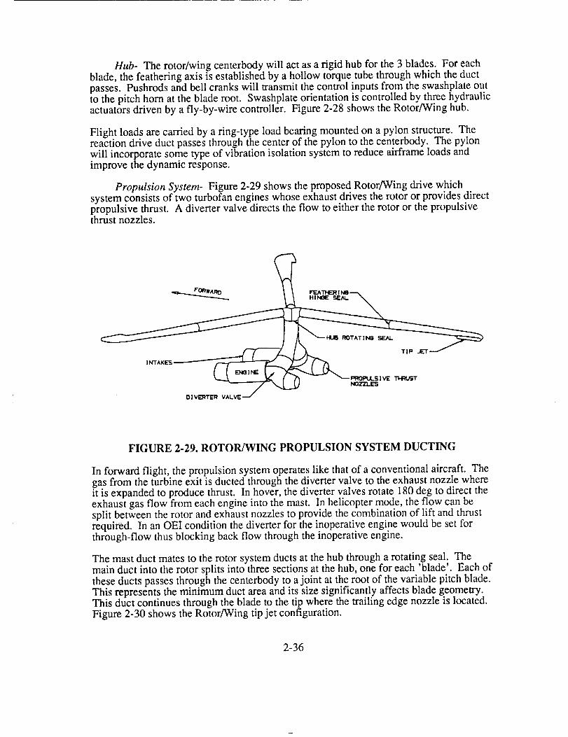
Hub- The rotor/wing centerbody will act as a rigid hub for the 3 blades. For eachblade, the feathering axis is established by a hollow torque tube through which the ductpasses. Pushrods and bell cranks will transmit the control inputs from the swashplate outto the pitch horn at the blade root. Swashplate orientation is controlled by three hydraulicactuators driven by a fly-by-wire controller. Figure 2-28 shows the Rotor/Wing hub.
Flight loads are carried by a ring-type load beating mounted on a pylon structure. Thereaction drive duct passes through the center of the pylon to the centerbody. The pylonwill incorporate some type of vibration isolation system to reduce airframe loads and
improve the dynamic response.
Propulsion System- Figure 2-29 shows the proposed Rotor/Wing drive which
system consists of two turbofan engines whose exhaust drives the rotor or provides directpropulsive thrust. A diverter valve directs the flow to either the rotor or the propulsivethrust nozzles.
_.._.._ F'ORWA RO _ FF.ATHE_ 1NO _.
IVIE T'HRI._T
D 1VEI:ITER VALVE
FIGURE 2-29. ROTOR/WING PROPULSION SYSTEM DUCT1NG
In forward flight, the propulsion system operates like that of a conventional aircraft. Thegas from the turbine exit is ducted through the diverter valve to the exhaust nozzle whereit is expanded to produce thrust. In hover, the diverter valves rotate 180 deg to direct theexhaust gas flow from each engine into the mast. In helicopter mode, the flow can besplit between the rotor and exhaust nozzles to provide the combination of lift and thrustrequired. In an OEI condition the diverter for the inoperative engine would be set forthrough-flow thus blocking back flow through the inoperative engine.
The mast duct mates to the rotor system ducts at the hub through a rotating seal. The
main duct into the rotor splits into three sections at the hub, one for each 'blade'. Each ofthese ducts passes through the centerbody to a joint at the root of the variable pitch blade.This represents the minimum duct area and its size significantly affects blade geometry.This duct continues through the blade to the tip where the trailing edge nozzle is located.
Figure 2-30 shows the Rotor/Wing tip jet configuration.
2-36

A
.',
SECTION A-A, SHI,,JTTER5 _LOSED/OPEN
FIGURE 2-30. ROTOR/WING TIP JET
The blade nozzles turn the flow 90 deg. and vent through pressure controlled shutters.The exit area, controlled by an electrical actuator, maintains optimum exit conditionsbased on internal pressure. When closed, the shutters maintain the outside contour of theairfoil to reduce drag in fixed wing mode.
Control System- The proposed Rotor/Wing control system must provide attitudeand directional control in hover, in forward flight with rotor turning, in fixed-wing flightto 450 kts, in auto gyro mode, and during acceleration and deceleration of the rotorduring transition. The system uses rudder and elevon control surfaces plus reaction yawcontrol jets on the tail, and controllable pitch blades on the rotor. Significant anti-torquecontrol capability is not required because the rotor is driven by reaction nozzles at theblade tips and no torque is transmitted to the airframe.
A triple redundant, double fail operative fly-by-wire system translates pilot inputs intocontrol device actuations. The control laws of the system vary depending on the flightmode/conditions.
In vertical flight, cyclic and collective blade control to the rotor are used for lateral andlongitudinal control. Reaction jets, using engine bleed air or a portion of the exhaust, aremounted in the tail for yaw control. Partially diverting some of the exhaust to thepropulsive thrust nozzles allows augmentation of the rotor propulsive thrust.
In fixed-wing mode, the elevons and rudder on the tail provide yaw, pitch, and rollcontrol with the rotor fixed and blade pitch locl4ed.
For conversion from rotary-wing to fixed-wing mode, exhaust flow diverts from the rotorto the propulsive thrust nozzles. Figure 2-31 shows the Rotor/Wing locking-stoppingmechanism. A brake slows and stops the rotor and a locking mechanism engages. Duringrotor deceleration, the elevons automatically actuate at 3/rev, independent of pilot inputs,to cancel rolling and pitching moments caused by a shifting aerodynamic center.
2-37
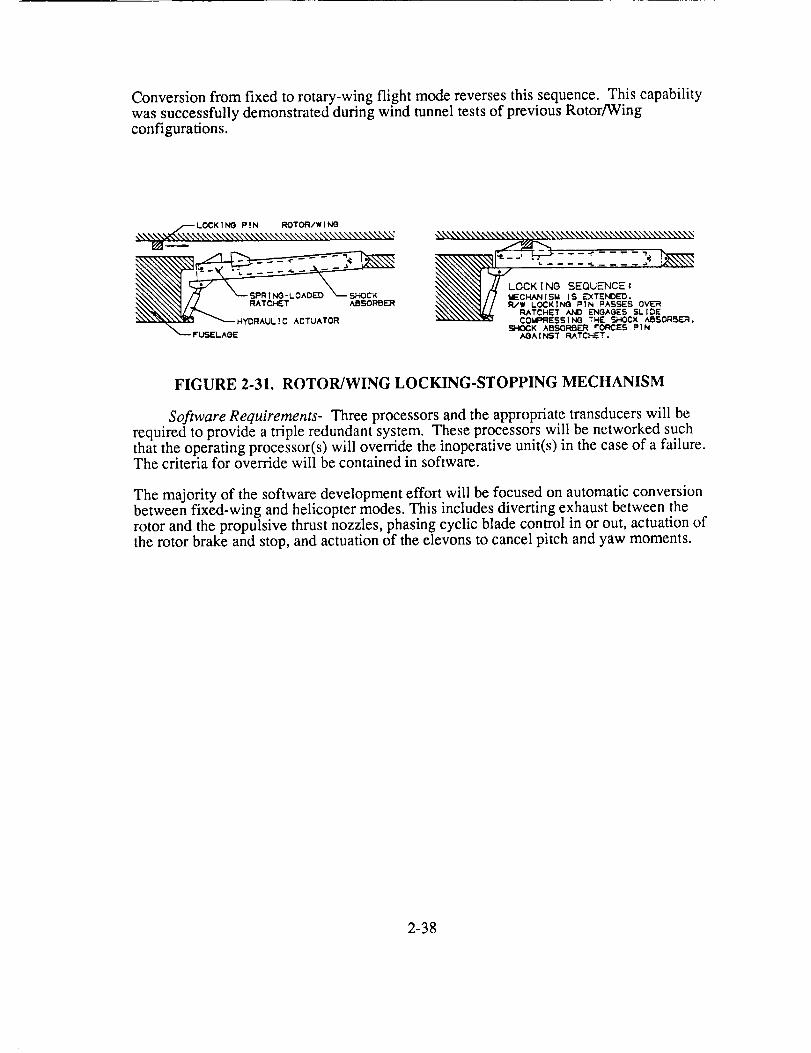
Conversionfrom fixed to rotary-wingflight modereversesthis sequence.This capabilitywassuccessfullydemonstratedduringwind tunneltestsof previousRotor/Wingconfigurations.
\\\_\\\\\\\\\\\,L0 CK I NO P ! N ROTOR/ WI
SHOCK
_\\\\\\\\\\\\\\\\\\\
OCK ! NG SEQUENCE •
CHANISM IS EXTENDED.
W LOCKING PIN !=ASE>ICS OVER
RATCHET AND ENGAGES SLIDECOMF:FIE$5|NO THE SHOCK ABSO,R_..R.
Si-IOCK ABSOF_ER ¢'ORCES PIN
AGA ! NST RATCHET.
FIGURE 2-31. ROTOR/WING LOCKING-STOPPING MECHANISM
Software Requirements- Three processors and the appropriate transducers will berequired to provide a triple redundant system. These processors will be networked suchthat the operating processor(s) will override the inoperative unit(s) in the case of a failure.The criteria for override will be contained in software.
The majority of the software development effort will be focused on automatic conversionbetween fixed-wing and helicopter modes. This includes diverting exhaust between therotor and the propulsive thrust nozzles, phasing cyclic blade control in or out, actuation ofthe rotor brake and stop, and actuation of the elevons to cancel pitch and yaw moments.
2-38
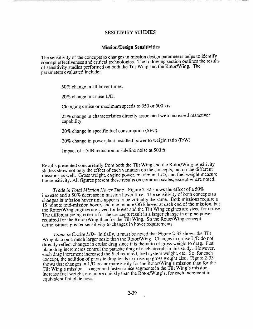
SESITIVITY STUDIES
Mission/Design Sensitivities
The sensitivity of the concepts to changes in mission design parameters helps to identifyconcept effectiveness and critical technologies. The following section outlines the resultsof sensitivity studies performed on both the Tilt Wing and the Rotor/Wing. Theparameters evaluated include:
50% change in all hover times.
20% change in cruise L/D.
Changing cruise or maximum speeds to 350 or 500 kts.
25% change in characteristics directly associated with increased maneuvercapability.
20% change in specific fuel consumption (SFC).
20% change in powerplant installed power to weight ratio (P/W)
Impact of a 5dB reduction in sideline noise at 500 ft.
Results presented concurrently from both the Tilt Wing and the Rotor/Wing sensitivitystudies show not only the effect of each variation on the concepts, but on the differentmissions as well. Gross weight, engine power, maximum L/D, and fuel weight measurethe sensitivity. All figures present these results on common scales, except where noted.
Trade in Total Mission Hover Time- Figure 2-32 shows the effect of a 50%increase and a 50% decrease in mission hover time. The sensitivity of both concepts to
changes in mission hover time appears to be virtually the same. Both missions require a15 minute mid-mission hover, and one minute OGE hover at each end of the mission, but
the Rotor/Wing engines are sized for hover and the Tilt Wing engines are sized for cruise.The different sizing criteria for the concepts result in a larger change in engine powerrequired for the Rotor/Wing than for the Tilt Wing. So the Rotor/Wing conceptdemonstrates greater sensitivity to changes in hover requirements.
Trade in Cruise L/D- Initially, it must be noted that Figure 2-33 shows the Tilt
Wing data on a much larger scale than the Rotor/Wing. Changes in cruise L/D do notdirectly reflect changes in cruise drag since it is the ratio of gross weight to drag. Flatplate drag increments control the parasite drag of each aircraft in this study. However,each drag increment increased the fuel required, fuel system weight, etc. So, for eachconcept, the addition of parasite drag tends to drive up gross weight also. Figure 2-33shows that changes in L/D occur more easily for the Rotor/Wing's mission than for theTilt Wing's mission. Longer and faster cruise segments in the Tilt Wing's missionincrease fuel weight, etc. more quickly than the Rotor/Wing's, for each increment in
equivalent flat plate area.
2-39

L)o<
Rotor/Wing
3O
2O
10
0
-10
-20
-30
i ................................................................................................................................
-_ " -50% Hover Time +50% Hover Time
Tilt Wing
¢:
.¢:(5
3O
2O
10
0
-10
-20
-30
I ................................................................................................................. - ...............
! ..................................................................................... "+'50% Hover-50% Hover
............................................................................................_...L............ ........................................................................
................... ,.oo, ................................................................................................. , ........
III Gross Weight _ Engine Power BB LJD max _ Fuel Weight
FIGURE 2-32. SENSITIVITY TO CHANGES IN MISSION HOVER TIME
3O
20¢::: 10¢-
0
o_ -10
-20
-30
80
_ 6O
o_ 40a;:O 20
o
-20
FIGURE 2-33.
Rotor/Wing+,. ..... +....o.,.o, ............. ° ............. , ................... - ...................... , .......... ,°+ ..................
| I J
Tilt Wing
:::::::::::::::::::::::::::::::::::::::::::::::::::::::::::::::::::::::::.......................;+_+-+],p-_-..............,............................. ,:_o+]<_-,o13.........................
1 Gross Weight _ Engine Power 1B L/D max r77_Fuel Weight
* (out of standard scale)
SENSITIVITY TO CHANGES IN L_T-TO-DRAG RATIO
2-40

Trade in Maximum Cruise Speed- Again, Figure 2-34 depicts the Tilt Wing data on
a much larger scale than the Rotor/Wing data. The Tilt Wing appears more sensitive tochanges in maximum cruise speed than the Rotor/Wing for several reasons. The TiltWing Cruises at 450 kts for 350 nm, while the Rotor/Wing cruises at 400 kts for only 50nm. The Tilt Wing is propelled by prop/rotors where the Rotor/Wing is propelled byturbofan engines. The efficiency drops off significantly for the prop/rotors after 450 kts,while the turbofan can still maintain efficient cruise at 500 kts. Finally, wing planform
and tilting requirements limit wing sweep on the Tilt Wing, while the three-bladedRotor/Wing incorporates 30 degrees of wing sweep automatically, delaying the onset of
drag divergence.
r-"t_
r-(.9
Rotor/Wing
30
20
10
0
-10
-20
-30
120
100
{:_ 80t-
60t--
C,,..) 40
_ 2o0
-20
..........................................................................................................350 kts Cruise
Tilt Wing
FIGURE 2-34.
!iii!I I
350 kts Cruise 500 kts Cruise
1 Gross Weight _ Engine Power m L/D max ezz_ Fuel Weight
" (out of standard scale)
SENSITIVITY TO CHANGES IN CRUISE SPEED
Trade in Maneuverability Characteristics- The sensitivity of changes inmaneuverability characteristics apply to two areas: rotor solidity and wing area. Thebaseline average hover lift coefficients for the Tilt Wing and Rotor/Wing are 0.89 and0.70, respectively. Figure 2-35 shows the affect of decreasing rotor solidity, or averagelift coefficient (if CT remains unchanged), by 25%. This figure shows the affect ofincreasing the hover g capability from 1.25g to 1.56g, and decreasing the hover gcapability to 0.94g for both aircraft (realistically, the latter would require additionalairfoil development). This change affects the Rotor/Wing engine sizing more than theTilt Wing, again, because the Rotor/Wing's engines size for hover and the Tilt Wing's forcruise. The large change in L/D for the Rotor/Wing reflects the dual role of the rotor as afixed-wing in cruise. The fuel weight of each concept is affected essentially the same.The Tilt Wing's gross weight changes more, however, due to a decrease in cruiseefficiency. This decrease has a large affect on the drive system weight, which is thelargest component weight of the Tilt Wing.
2-41
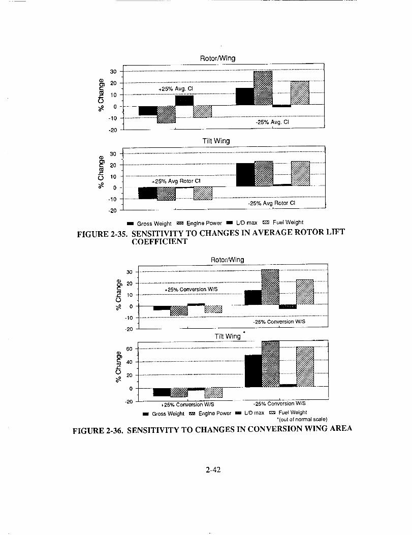
e--
O
Rotor/Wing
30
20
10
0
-10
-20t -25% Avg. CI
30-
20
O lO-
o-
-10
-20 -
Tilt Wing
.................:;_;=_;__o;o;c;......................._ii
-25°/oAvg Rotor CII -1
m, Gross Weight _ Engine Power I L/D max _m Fuel Weight
FIGURE 2-35. SENSITIVITY TO CHANGES IN AVERAGE ROTOR LIFTCOEFFICIENT
Rotor/Wing
30 ..............................................................................o_°_oiiiiiiii:iiiii:iiiiii;iciiiiiiiiiii:_i_i:i:i:ii:iiiiiiii_.c: 10
O
_ o_.,o ...................:_;;Conie;_io__i;.............;-20
Tilt Wing *
o.°o iiill¢..
0 20
0 i i_ -
_ 20
+25% Conversion W/S -25% Conversion WJS
w Gross Weight _ Engine Power i L/D max _ Fuel Weight
'(out of normal scale)
FIGURE 2-36. SENSITIVITY TO CHANGES IN CONVERSION WING AREA
2-42

Another maneuverability study reflects changes in wing area. The baseline conversionwing loading for the Tilt Wing is 90 psf. The baseline conversion wing loading for theRotor/Wing is 65 psf. Changes in conversion wing area affect the flight regime mostsensitive to maneuvering flight. In fact, no difference exists between conversion andcruise wing area for the Tilt Wing, and the Rotor/Wing conversion wing area makes up79% of the cruise wing area. Figure 2-36 shows the affect of 25% change in conversion
wing loading. Once again, the Tilt Wing data is on a larger scale than the Rotor/Wingdata. Since the disk loading is not changed, the Rotor/Wing experiences large changes ineffective rotor area due to changes in the centerbody radius. This accounts for theincreased Rotor/Wing engine sizing. Several factor account for the large changes in TiltWing gross weight, engine sizing, and fuel weight. The Tilt Wing sees the same changein cruise wing area as it does in conversion wing area. This change not only reflects inthe empty weight of the aircraft, but also affects the cruise profile drag. This, in turnaffects the fuel consumption and the engine sizing.
Trade in SFC- Figure 2-37 shows that the Tilt Wing and the Rotor/Wing areaffected nearly the same by changes in SFC (or fuel flow). Like the mission hover timetrade study, variation in SFC affects engine sizing of the Rotor/Wing more than the TiltWing. Since the Rotor/Wing engines size for hover, their sizing will be more effected bychanges in gross weight than the engines of the Tilt Wing, which are sized for cruise.
Rotor/Wing
-2o Foe,Row 2o Fue,F,ow• 20
_ 10r.- .o o
" iiiiiiiiii21111111111111111111111111111111111111111111111111111111111111_ -lO .
I I
-2O
-30
Tilt Wing
30
i-- lOoN o
-lO
-20
-30
................. ................................
FIGURE 2-37.
== Gross Weight _a Engine Power =_ L/D max r7_ Fuel Weight
SENSITIVITY TO CHANGES IN FUEL FLOW
Trade in installed P/W- Figure 2-38 shows the effect of P/W on the Tilt Wing andRotor/Wing. Changing P/W does not have as large of an effect on the concepts as theother sensitivities, but it does appear to effect the Tilt Wing more than the Rotor/Wing.The engines account for a slightly larger percentage of the gross weight of the Tilt Wing
2-43

thanfor theRotor/Wing(7.00%ascomparedto 6.55%).Changesin engineweightreflectchangesin theengineinstallation,drive system,etc.,while theRotor/Winghasfewercomponentsaffectedby engineweight.
Rotor/Wing
dEO
3O
2O
10
0
-10
-20
-30
......................................................................................................
I
o
3O
20
10
0
-10
-20
-30
== Gross Weight _ Engine Power === L/D max _ Fuel Weight
FIGURE 2-38. SENSITIVITY TO CHANGES IN ENGINEPOWER-TO-WEIGHT RATIO
50
0)
t-O
4O
3O
2O
10
-10I I
Rotor/Wing liltwing
[] Gross Weight [] Engine Power [] I../Dmax [] Fuel Weight
FIGURE 2-39. SENSITIVITY TO A 5 dB SIDELINE NOISE REDUCTION
2-44

5dB Noise Reduction: A 20% reduction in tip speed reduces the sideline noise at500 ft by approximately 5 dB. Figure 2-39 shows the effect of reducing the tip speed20% on both concepts. Tip speed reduction results in a larger rotor system, because Cx
increases, but maximum Cr/_ does not. The same disk loading then requires muchhigher solidities to keep the rotor from stalling. This affects the engine sizing of theRotor/Wing more than the Tilt Wing, again due to engines being sized for hover, and theincreased profile power due to its resulting high solidity rotor. The reduction in tip speedreduces the prop/rotor cruise efficiency, due to larger solidities needed to prevent rotorstall. This greatly increases the drive system weight, the single heaviest component. Forthis reason, the Tilt Wing experiences the larger change in gross weight due to tip speedreduction.
Conclusions
The sensitivity studies help to define technology areas which would most benefit eachconcept at its chosen mission. Several conclusions as a result of the studies are:
.
.
.
.
o
The largest benefits for these concepts will come from improvements in engineSFC.
450 kts represents the efficient cruising limit for current prop/rotor-drivenV/STOL aircraft. Beyond this speed, propulsive efficiency drops dramatically,resulting in greater power required and higher gross weights.
The Rotor/Wing concept shows a potential for higher cruise speeds withoutsevere penalties in gross weight.
Increases in control surface area (wing, rotor, empennage, etc.) for increasedmaneuverability or noise reduction result in large cruise efficiency penalties,which may not justify the increase.
The Rotor/Wing is the most sensitive to changes in hover time due to its enginesbeing sized by the hover requirement.
Technology Sensitivities
Achievable technologies will determine the potential of both the Tilt Wing and theRotor/Wing. A brainstorming session produced the technology matrix shown in Table2-9. The matrix represents six technology areas for the Tilt Wing and five for theRotor/Wing. Independent application to each concept illustrates the impact of eachtechnology. Application of all technologies indicates the size and shape of future TiltWing and Rotor/Wing aircraft.
2-45

In Task 1,velocity-dependentmeasuresof effectivenessindicatedtheeffectof eachtechnology.Thisprovidedusefulinformationon theefficiencyof theaircraftatvariousspeeds.However,Task 1 used a simple mission cruising at 450 knots, bracketed by shorthover segments. Task 2 utilizes two different missions for the Tilt Wing and theRotor/Wing. These missions include longer periods of hover, mingled with dash andloiter segments at speeds varying from 150 to 450 knots. Since the mission of eachspecifies a payload, speed and range, these parameters remain constant and the measuresof effectiveness of Section 1 reduce to those shown in table 2-10.
TECHNOLOGY ROTOR/WING TILT WING
Materials & Overall Weight Overall WeightStructure (-15% Primary Structure) (-15% Primary Structure)
(-10% Secondary Structure) (-10% Secondary Structure)
Propulsion
Drive Train
Aerodynamics
Flight Controls
Subsystems
IHPTET Goals
1(-30.0 SFC, +120% T/W)
N/A
Reduce Cruise Airfoil Drag(-12.3% Drag Coefficient)Increase Conversion WingLoading (90 psf)
Reduce Empennage Size(-15% Area)Reduce Weight (-10%)
Reduce Weight (-10%)
IHPTET Goals
(-35.5% SFC, +100% P/W)Cruise Efficiency(+8.3% Cruise Efficiency)
ART Goals
(-20% Gear Box Weight)(-25% Driveshaft Weight)
High Drag Divergence(MoD = 0.75)Increase Conversion WingLoading (120 psf)
Reduce Empennage Size(-15% Area)Reduce Weight (-10%)
Reduce Weight (-10%)
TABLE 2-9. ACHIEVABLE TECHNOLOGY MATRIX
These new measures can compare the effectiveness of the vehicles with advancedtechnology to the baseline vehicles using the same mission. The values presented in table2-10 represent the measures of effectiveness values for the current technology baselinevehicles and are used as the basis for determining percent improvements of advanced
technology over current technology. The definitions of the new measures ofeffectiveness are as follows:
Gross Weight
Mission Productivity = Wp,_ /We,,,p
Mission Efficiency = Wp,_/Wl,,,t
Specific Range = Vd_h /(VI,,,,
2-46

Measuresof Effectiveness
GrossWeight (lbs)Mission ProductivityMissionEfficiencySpecificRange(Nm/lb)
Tilt Wing578810.15090.49630.0729
Rotor/Wing281210.17320.38470.0782
TABLE 2-10. CURRENT TECHNOLOGY MEASURES OF EFFECTIVENESS
From these baselines, each advanced technology was applied individually to each conceptand a sensitivity to achieving the technology goals was assessed.
Technology Weight Factor Assumptions- The general weight assumptions appliedin Task II are as follows:
Those structural weight groups which are currently of "conventional" constructionwill decrease in weight by 15%.
Those structural weight groups which are currently using some level of compositeswill decrease in weight by 10%.
Drive System: ART goals require a 25% decrease in total drive system weight. Forthis study assumed onIy 20% reduction in the gearbox weights but the full 25%reduction in the driveshafts.
Landing Gear: Composite gear design; weight savings of 15%.
Engine: Phase III IHPTET level of technology was assumed.
No weight savings were assumed in the following areas:
1. Rotor Blades
2. Propulsion Subsystems3. Fuel System4. Flight Controls
The following figures show the effect of each technology, at the desired technology goal,and also present the effect if the goal is exceeded or falls short by 15%. The figurespresent this information as a percentage change from the current technology baselinesshown above.
Tilt Wing-
General Weight Reduction: Figure 2-40 shows the impact of a general weightreduction (neglecting the drive system, which will be varied separately) reflectingmaterials and structures technology available in 2003. As expected, the largest gain is inMission Productivity which indicates the empty weight needed to carry the requiredpayload.
2-47
3O
" 2O
0
u. 0
0
_ -10
-20
iiiiiiiiiiiiiiiiiiiiiiiiiiiiiiiiiiiiiii•
J- 1 1 .L_
Gross Weight M;ssion Productivity Mission E_dency Specific Range
• Fails Goal by 15% [] Technology Goal [] Exceeds Goal by 15%
FIGURE 2-40. TILT WING : EFFECT OF A GENERAL WEIGHT REDUCTION
The fairly large change from 15% failure to 15% excess of the goal shows, at least, thatthe Tilt Wing transport is fairly sensitive to level of materials and structures technologyimplemented. This seems reasonable because the weight reduction affects virtually everycomponent of the aircraft both directly and indirectly.
30
_8'O
O
I.l. 0
e-
o_ -I0
-20
FIGURE 2-41.
I I _ I I
Gross Weight Mission Productivity Mission Efficiency Specific Range
• Fails Goal by 15% [] Technology Goal [] Exceeds Goal by 150/0
TILT WING : EFFECT OF A REDUCTION IN WING
THICKNESS (18% - 14%) WITH NO CHANGE IN WEIGHT
2-48

Wing ThicknessReduction:Reducingwing thicknessfrom 18%to 14%,throughanadvancementin structuresandmaterials,decreaseswing profile dragwith nochangein wing weight. Figure 2-41showstheimpactof areductionin wing thickness.Thistechnologyusescompositeswith advancedweavingmethodsto maintainstrengthandstiffness.Figure2-41indicatesthatthe largestincreasesarein MissionEfficiency (fuelweight)andSpecificRange(fuel consumption).
Reductionin SFC: Figure2-42showstheeffectof reducingSFCof theAllisonT406 turboshaftengineby 35.5%overthecurrentSFC. ThisvaluerepresentsPhaseII!IHPTET goalsappliedto theT406by Allison.
12O
>, tO0
60
0 40
u. 20
o
N -2o
-40
ii!iii!iiiiiiiiiiiiii!iiiiii!iiiiiiiiiillGross Weight Mission Productivity Mission Efficiency Specific Range
• Falls Goal by 15"/* [] Technology Goal [] Exceeds Goal by 15"/*
Not NormeJScde
FIGURE 2-42. TILT WING : EFFECT OF A 35.5% REDUCTION IN SFC
The scales of Figure 2-42 are expanded compared to previous graphs. The reduced fuelweight also causes a reduction in empty weight of the same order of magnitude as thegeneral weight reduction, but no component weights were directly reduced. Huge gainsin all measures indicate the tremendous impact possible if the IHPTET goals are realized.Although these goals appear to be very difficult to achieve, engine performance remainsone of the most significant technology improvement areas.
Increase in Engine Power-to-Weight Ratio (P/W): Figure 2-43 shows the effect ofincreasing the engine power-to-weight ratio by 100% from the current ratio of 6.3 HP/Ib,as specified by the Phase III IHPTET goals.
The four primary engines make up 10.2% of the total empty weight of the currenttechnology Tilt Wing. Increasing the P/W of the engines equates (before resizing) tocutting their weight in half. This means that a 100% reduction in P/W should provide a5% decrease in empty weight (before resizing). Figure 2-43 shows an almost 20%increase in Mission Productivity reflecting an equivalent decrease in empty weight. Thisshows a large dependence of the empty weight on the weight of the primary engines dueto changes in the weight of the drive system, engine installation, wing, etc.
2-49
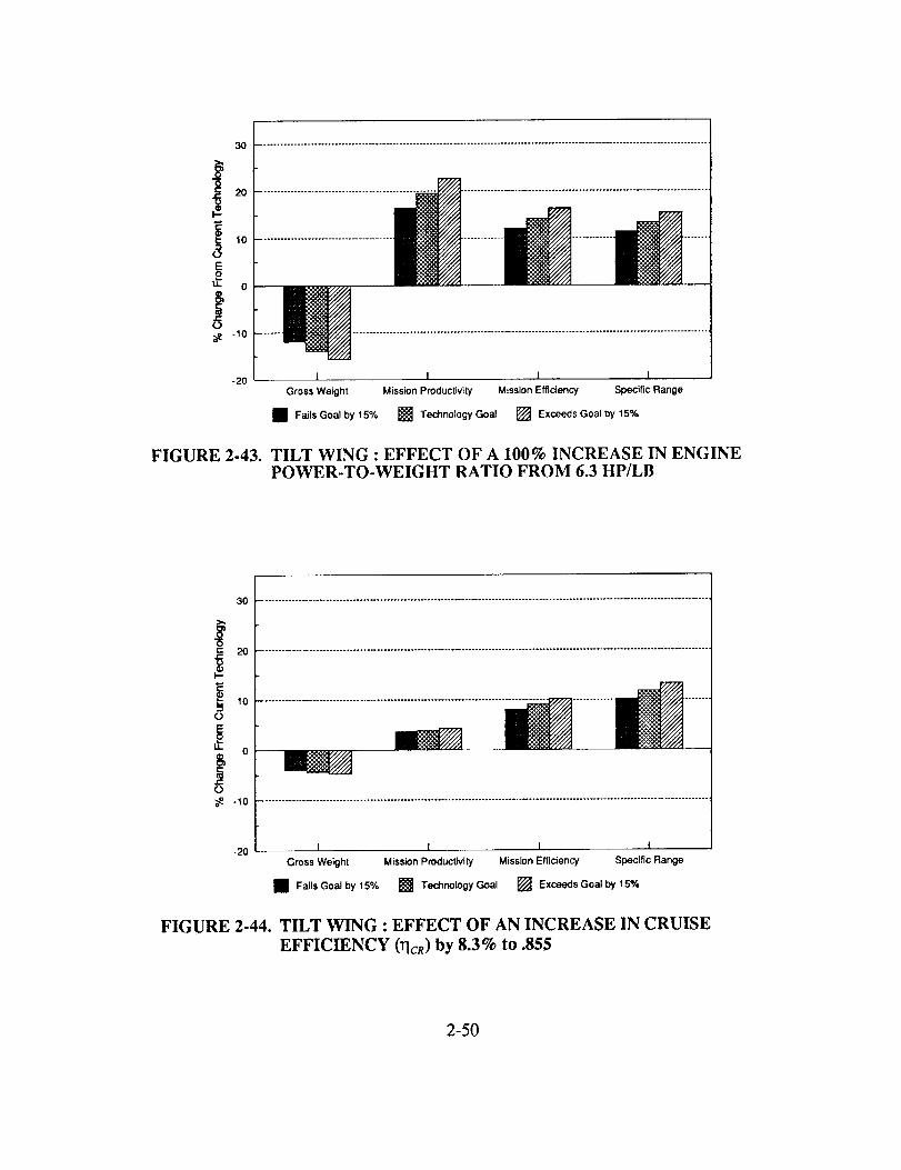
3O
_2o
EO
u- 0
-I0
-2O
iiiiiiiiiiiiiiiiiiiiiiiiiiiiiiiiiiiii
I I I I
Gross Weight Mission Productivity Mission Efficiency Specific Range
• Fails Goal by 15% [] Technology Goal [] Exceeds Goal by 15%
FIGURE 2-43. TILT WING : EFFECT OF A 100% INCREASE IN ENGINEPOWER-TO-WEIGHT RATIO FROM 6.3 HP/LB
t--
*.d
It.
o
3o
2o
o t.,of...............:.................................................................................................:.................-20 I I
Gross Weight Mission Productivity Mission Efficiency Specific Range
• Fails Goal by 15% [] Technology Goal [] Exceeds Goal by 15%
FIGURE 2-44. TILT WING : EFFECT OF AN INCREASE IN CRUISE
EFFICIENCY (qcR) by 8.3% to .855
2-50
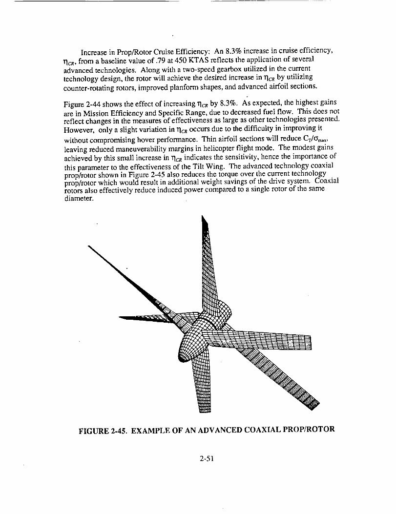
Increasein Prop/RotorCruiseEfficiency: An 8.3%increasein cruiseefficiency,rlcR,from abaselinevalueof .79at450 KTAS reflectstheapplicationof severaladvancedtechnologies.Along with atwo-speedgearboxutilized in thecurrenttechnologydesign,therotor will achievethedesiredincreasein rlcnby utilizingcounter-rotatingrotors,improvedplanformshapes,andadvancedairfoil sections.
Figure2-44 shows the effect of increasing rlcR by 8.3%. As expected, the highest gains
are in Mission Efficiency and Specific Range, due to decreased fuel flow. This does notreflect changes in the measures of effectiveness as large as other technologies presented.
However, only a slight variation in rlcR occurs due to the difficulty in improving it
without compromising hover performance. Thin airfoil sections will reduce Cr/_m,x,
leaving reduced maneuverability margins in helicopter flight mode. The modest gains
achieved by this small increase in rlcR indicates the sensitivity, hence the importance of
this parameter to the effectiveness of the Tilt Wing. The advanced technology coaxialprop/rotor shown in Figure 2-45 also reduces the torque over the current technologyprop/rotor which would result in additional weight savings of the drive system. Coaxialrotors also effectively reduce induced power compared to a single rotor of the samediameter.
FIGURE 2-45. EXAMPLE OF AN ADVANCED COAXIAL PROP/ROTOR
2-51

3O
@ 2o
t-
10
8
_ o
-20 I I I I
FIGURE 2-46.
Gross Weight Mission Productivity Mission Efficiency Specific Range
• Fails Goal by 15% [] Technology Goal [] Exceeds Goal by 15%
TILT WING : EFFECT OF A 20% REDUCTION IN GEARBOX WEIGHT AND 25% IN DRIVE SHAFT WEIGHT
3O
EO
_- o
¢j
-20I t I I
Gross Weight Mission Productivity Mission Efficiency Specific Range
• Fails Goal by 15% [] Technology Goal [] Exceeds Goal by 15%
FIGURE 2-47. TILT WING: EFFECT OF INCREASING WING AIRFOIL
MD. TO 0.75 FROM 0.714.
Reduction in Drive System Weight: The drive system represents the single heaviestcomponent in the Tilt Wing, mainly due to the two-speed gearbox and the high powerrequirements in cruise. The Advanced Rotor Transmission (ART) goals dictated a 20%
2-52

reductionin total gearbox weight and a 25% reduction in total shaft weight TM. Based oncurrent progress in the ART program, these goals appear achievable. Figure 2-46 showsthe effect of the ART goals on the measures of effectiveness.
Although the drive system represents a larger percentage of the empty weight than theprimary engines, the ART goals do not effect the measures of effectiveness as strongly asthe IHPTET engine weight reduction. This is for two reasons. The IHPTET goalsrepresent a 50% reduction in engine weight, while the ART goals represent less than a25% reduction in drive system weight. Also, more Tilt Wing subsystem weights aredriven by the weight of the engines than the drive system.
Increase Wing Drag Divergence Mach Number (/VIDD): The current technology TiltWing utilizes a supercritical wing section with a zero-lift MDD of 0.714. Figure 2-47shows the effect of using an airfoil with the same incompressible lift and drag propertiesas the current technology Tilt Wing, but with a higher MDD-
The highest Mach number that is achieved during the Tilt Wing's mission is 0.698 at alift coefficient of 0.20. Thus the wing, although close to MDD, does not exceed it withcurrent technology (see Figure 1-25). Therefore, Figure 2-47 shows only small gains inthe measures of effectiveness when the MDD is increased. Increasing the MDD of theairfoil allows cruising at a higher altitude if the wing were the only consideration. Sincethe prop/rotor must also be considered, the reduction in cruise propulsive efficiency willoutweigh the reduction of drag obtained at a higher altitude. The combination ofimproved wing and prop/rotor efficiency would improve the effectiveness of the aircraftsimply by allowing to cruise at higher altitudes. Only increased speed capability willrequire development of airfoils which delay MDD beyond current capabilities.
3O
O
u. 0
g
e-
(9
-20
......................................................................................................................
I I I___
Gross Weight Mission Productivity Mission Efficiency Specific Range
[] Fails Goal by 15% [] Technology Goal [] Exceeds Goal by 15%
FIGURE 2-48. TILT WING: EFFECT OF INCREASING CONVERSION WINGLOADING TO 120 PSF FROM 90 PSF.
2-53

Increasein ConversionWingLoading: Theamountof wing areaneededto carrytheTilt Wing throughconversion,andespeciallyreconversionis generallymuchmorethandesiredfor cruiseathigh speed.Figure2-48showstheeffectof increasingconversionwing loading(equalto t_eoff wing loading)from 90psf to 120psf.
This decreasein wing arearesultsin ahugeincreasein MissionEfficiency andSpecificRange,asthelargedecreasein cruisedragwoulddictate. Thelargeincreasein MissionProductivityreflectsdirectreductionsin drive systemandpropulsionweightdueto lowercruisepowerrequired.In fact,hoversizestheenginesin thiscase,notcruiseasbefore.Theexacttechnologyneededto reducethewing areamayarisethroughseveralmeans.Possiblesolutionsincludeacirculationcontrolwing (utilizing theexcesspowerneededfor cruise)or ageared-flaparrangementwhichallowsthewing to moveindependentoftherotors.
Applicationof ActiveFlight Controls: As describedin previoussections,tailvolumecoefficientsfrom previousTilt Wing designsdeterminedthesizeof thecurrenttechnologyTilt Wing. It is estimatedthattheapplicationof activeflight controlswillallow a 15%reductionin empennagesize. Figure2-49showstheresultsof thisreduction.
3O
O
¢ 2o
E0
u. 0
8_ -1o
-20 I I I I
Gross Weight Mission Productivity Mission Efficiency Specific Range
• Fails Goal by 15% [] Technology Goat [] Exceeds Goal by 15%
FIGURE 2-49. TILT WING : EFFECT OF REDUCINGEMPENNAGE SIZE 15% DUE TO APPLICATIONOF ACTIVE CONTROLS.
The effect on the measures of effectiveness is small, but noticeable. Note that the smaller
empennage affects Mission Productivity and Mission Efficiency similarly, denoting areduction in structure weight and an increase in cruise efficiency, due to reduced drag.
2-54
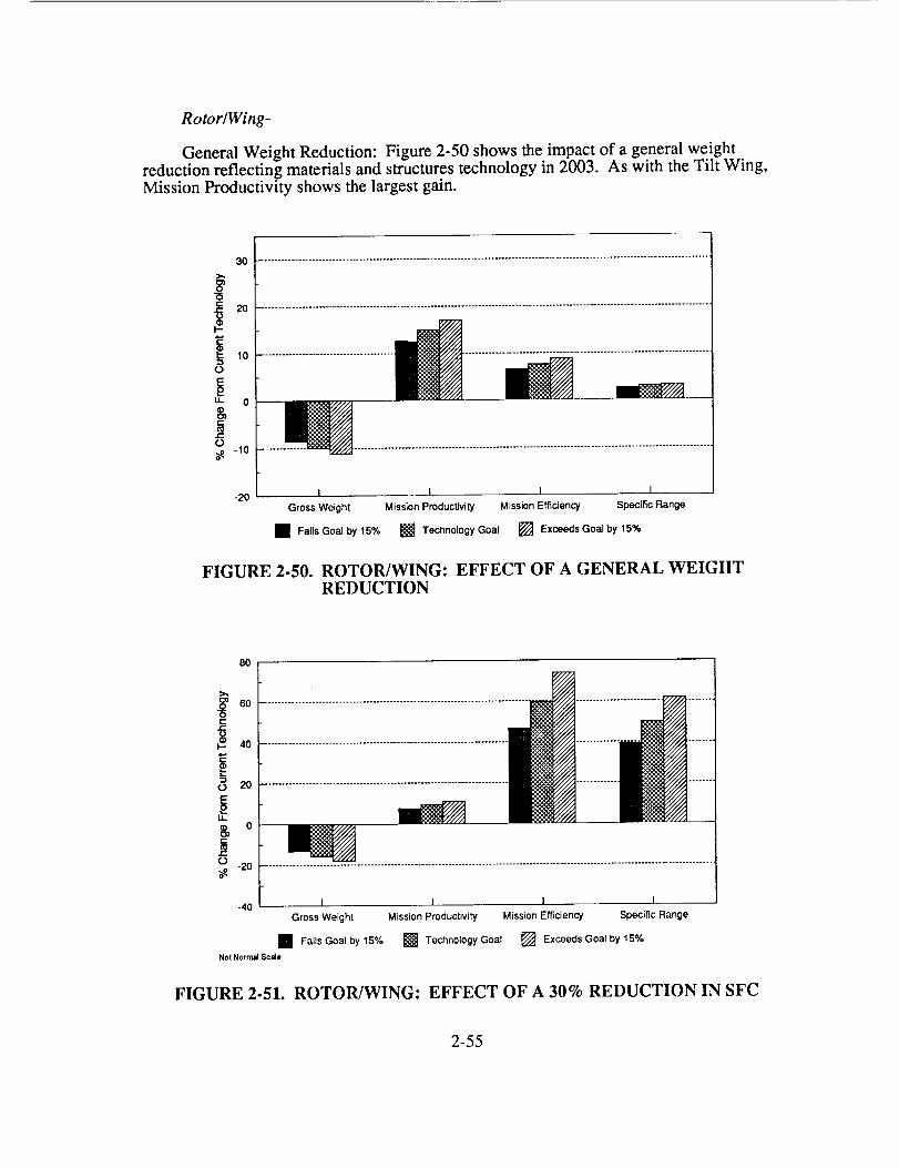
Rotor�Wing-
General Weight Reduction: Figure 2-50 shows the impact of a general weightreduction reflecting materials and structures technology in 2003. As with the Tilt Wing,Mission Productivity shows the largest gain.
3O
10o
" 0
§e-¢.)
-1o
-20 I I I I
Gross Weight Misslon Productivity Mission Efficiency Specific Range
[] Fails Goal by 15% [] Technology Goal [] Exceeds Goal by 15% .
FIGURE 2-50. ROTOR/WING: EFFECT OF A GENERAL WEIGHTREDUCTION
8O
60r--
o 2O
ii
$, o
r--
¢..) -20
-40 I I I I
Gross Weight Mission Productivity Mission Efficiency Specific Range
[] Fails Goal by 15% [] Technology Goal [] Exceeds Goal by 15%
Not Norrn_ SceJe
FIGURE 2-51. ROTOR/WING: EFFECT OF A 30% REDUCTION IN SFC
2-55
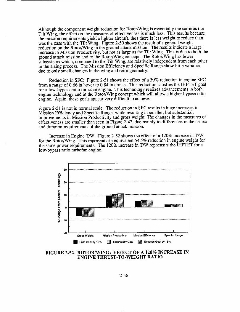
Althoughthecomponentweightreductionfor Rotor/Wingis essentiallythesameastheTilt Wing, theeffecton themeasuresof effectivenessis muchless. Thisresultsbecausethemissionrequirementsyield a lighteraircraft,thusthereis lessweight to reducethanwasthecasewith theTilt Wing. Figure2-50showstheresultof ageneralweightreductionon theRotor/Wingin thegroundattackmission. Theresultsindicatea largeincreasein MissionProductivity,butnotaslargeastheTilt Wing. This is dueto both thegroundattackmissionandto theRotor/Wingconcept.TheRotor/Winghasfewersubsystemswhich,comparedto theTilt Wing, arerelatively independentfrom eachotherin thesizingprocess.The MissionEfficiencyandSpecificRangeshowlittle variationdueto only smallchangesin thewing androtorgeometry.
Reductionin SFC: Figure2-51showstheeffectof a 30%reductionin engineSFCfrom arangeof 0.66in hoverto 0.84in cruise.ThisreductionsatisfiestheIHPTET goalfor a low-bypassratio turbofanengine.This technologyrealizesadvancementsin bothenginetechnologyandin theRotor/Wingconceptwhichwill allow ahigherbypassratioengine. Again, thesegoalsappearverydifficult to achieve.
Figure2-51 is not in normalscale.Thereductionin SFCresultsin hugeincreasesinMissionEfficiencyandSpecificRange,while resultingin smaller,butsubstantial,improvementsin MissionProductivityandgrossweight.Thechangesin themeasuresofeffectivenessaresmallerthanseenin Figure2-42,duemainly to differencesin thecruiseanddurationrequirementsof thegroundattackmission.
Increasein EngineT/W: Figure2-52showstheeffectof a 120%increasein T/Wfor theRotor/Wing. This representsanequivalent54.5%reductionin engineweightforthesamepowerrequirements.The 120%increasein T/W representstheiHPTET for alow-bypassratio turbofanengine.
3O
O
tl. O
8,
-2OI I I I
Gross Weight Mission Productivity Mission Efficiency Specific Range
I Fails Goal by 15% [] Technology Goal [] Exceeds Goal by 15%
FIGURE 2-52. ROTOR/WING: EFFECT OF A 120% INCREASE INENGINE THRUST-TO-WEIGHT RATIO
2-56

Thelargerincreasein engineT/W for theRotor/WingovertheTilt Wing, producesasmallerchangein themeasuresof effectiveness.Thereaction-driverotor, without adrivetrain, hasfewerpartsdirectly associatedwith theprimaryengines.Therefore,theRotor/Wing'sengineweightdoesnoteffectasmanycomponentsasdoestheTilt Wing's.
Decreasein CruiseWingDrag: Figure2-53showsa 12.3%decreasein cruisewingdrag,whichrepresentsthedragof anairfoil with thesame18% thickness,but with asharptrailing edge. Thisoccursdueto thereductionin thebladedragcoefficientfrom0.018to 0.011,notingthatthebladearearepresentsonly 35%of thewing referencearea.Theexcesspowerin cruisecouldallow bleedair to supplyboundarylayercontrol (BLC)to thestoppedrotorbladesandthecenterbody.Thepressurizedductsin therotorfacilitatethe incorporationof aBLC design.
30
C
o -I0
-20 1 I I 1.
Gross Weight Mission Productivity Mission Efficiency Specific Range
• Falls Goal by 15% [] Technology Goal [] Exceeds Goal by 15%
FIGURE 2-53. ROTOR/WING: EFFECT OF A 12.3% REDUCTION INCRUISE WING DRAG
Figure 2-53 shows almost no effect on any of the measures of effectiveness by decreasingwing drag. The ground attack mission requires a 400 kts dash for only 50 nm. The restof the mission is hover, 40 kts helicopter mode flight, and 140 kts best range flight. Wingprofile drag is not as large a factor as rotor profile drag, or induced drag. Also, the wingrepresents only 34% of the parasite drag. While large, this percentage reduces the totalparasite drag reduction in this case to only 4.18%. This could be more important for alonger range mission.
Increase in Conversion Wing Loading: The conversion wing loading is one of themain considerations when sizing the Rotor/Wing. Unfortunately, addition of high-liftdevices or other means of reducing conversion wing loading is not possible. This isbecause the centerbody rotates while carrying the full weight of the aircraft. Increasingthe conversion wing loading from 65 psf to 90 psf requires replacing the centerbody with
2-57

alternatelifting surfaces.Thesesurfacesprovidelift duringconversion,carryingtheweightof theaircraft,while therotor stops.Becausethesesurfacesprovidelift moreefficiently thanthecenterbody,theycanbemadesmaller,thusreducingdrag.
20
! lo
-10
-2O ± J 1 l
Gross Weight Mission Productivity Mission Efficiency Specific Range
FIGURE 2-54. ROTOR/WING: EFFECT OF INCREASING CONVERSIONWING LOADING TO 90 PSF FROM 65 PSF
3O
i,°EO
d: o
-10
-2O I I I I
Gross Weight Mlsslon Productivity Mission Effldency Specific Range
• Fails Goal by 15% [] Technology Goal [] Exceeds Goal by 15%
FIGURE 2-55. ROTOR/WING: EFFECT OF A 15% REDUCTION INEMPENNAGE SIZE
2-58

Figure2-54showsvery little gain in themeasuresof effectiveness,with theexceptionofMissionEfficiency (areflectionof lesscruisewing area,andtherefore,drag). Themeritof thisconfigurationlies in aircraftandrotordynamicsduringconversion.Sincetheangleof attackof the lifting surfacesis independentof therotordiskplane,therotor isoff-loadedin forwardflight, reducingvibration. At conversionspeeds,the liftingsurfacescompletelyoff-load therotor prior to stopping.Thisconfigurationdoesnotrequirethepitchup into autogyromodeasbefore,makingconversionmuchsmootherandlessrestricted. Analysisof thisconfigurationusingCAMRAD JA showsgreatpromiseduringconversion,in regardsto vibrationalleviation.Thisreductionmayalsoallow atwo-bladedconfiguration(whichwaspreviouslynotconsidereddueto largerotorvibrationin helicoptermode),whichwould furtherreducethecruisedrag.
Applicationof Active Flight Controls: Figure2-55showstheresultof a 15%reductionin horizontalandverticaltail sizethroughactivecontrols. Little effecton themeasuresof effectivenessis shown,althoughMissionEfficiencyandSpecificRangeareaffectedslightly morethangrossweightandMissionProductivity. Again, thedecreasein tail sizedoesnot significantlyaffectMissionEfficiencyor SpecificRangebecauseofthegroundattackmission. Also, the empennage does not represent a very large fractionof the gross weight, therefore, a 15% reduction in empennage size will not significantlyaffect Mission Productivity.
Identification of Critical Technologies
The study of achievable technology goals identifies which technology areas will providethe greatest benefit if implemented into the Tilt Wing and the Rotor/Wing. Certainly anyadvancements in engine technology will increase the effectiveness of both concepts. Theengine manufacturers admit that the Phase III IHPTET goals are very aggressive, andtherefore actual improvements in fuel economy and T/W may be significantly lower.Increases in allowable conversion wing loading help both concepts, but for differentreasons. The Tilt Wing benefits from a decrease in cruise wing drag, and the Rotor/Wingbenefits through easier conversion.
The general weight reductions can only be realized if the future concepts use theadvanced materials and structures effectively. Current applications of advancedcomposites have failed to realize weight or cost savings. These advancements, alongwith the engine advancements will benefit all aircraft concepts, not simply the high-speedrotorcraft concepts. Therefore, the means by which the Tilt Wing and Rotor/Wingbecome more effective as a transport or ground attack aircraft compared to conventionalaircraft, is by reducing the penalty to convert at low speeds from helicopter to fixed-wingflight. The Tilt Wing has shown gains in efficiency over other concepts, and theRotor/Wing has shown gains in ease of conversion. A different, more cruise-intensivemission would also show significant increases in Mission Efficiency and Specific Rangefor the Rotor/wing with a reduced conversion wing loading. The two most successfulVTOL concepts currently flying, the Harrier and the Tilt Rotor, do this, but with penaltiesin hover and high-speed flight respectively. For the Tilt Wing and Rotor/Wing,increasing the wing loading needed for conversion achieves the necessary reduction inthose penalties.
2-59
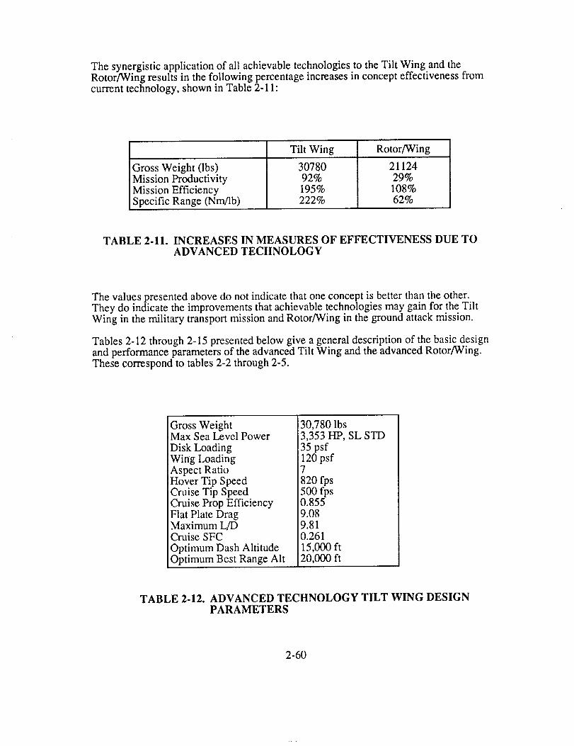
The synergisticapplicationof all achievabletechnologiesto theTilt Wing andtheRotor/Wingresultsin thefollowing percentageincreasesin concepteffectivenessfromcurrenttechnology,shownin Table2-11:
GrossWeight (lbs)MissionProductivityMissionEfficiencySpecificRange(Nm/lb)
Tilt Wing
3078092%195%222%
Rotor/Wing
2112429%108%62%
TABLE 2-11. INCREASES IN MEASURES OF EFFECTIVENESS DUE TOADVANCED TECHNOLOGY
The values presented above do not indicate that one concept is better than the other.They do indicate the improvements that achievable technologies may gain for the TiltWing in the military transport mission and Rotor/Wing in the ground attack mission.
Tables 2-12 through 2-15 presented below give a general description of the basic designand performance parameters of the advanced Tilt Wing and the advanced Rotor/Wing.These correspond to tables 2-2 through 2-5.
Gross WeightMax Sea Level Power
Disk Loading
Wing LoadingAspect RatioHover Tip SpeedCruise Tip SpeedCruise Prop EfficiencyFlat Plate DragMaximum L/DCruise SFC
Optimum Dash AltitudeOptimum Best Range Alt
30,780 lbs3,353 HP, SL STD
35 psf120 psf7
820 fps500 fps0.8559.089.810.26115,000 ft20,000 ft
TABLE 2-12. ADVANCED TECHNOLOGY TILT WING DESIGNPARAMETERS
2-60
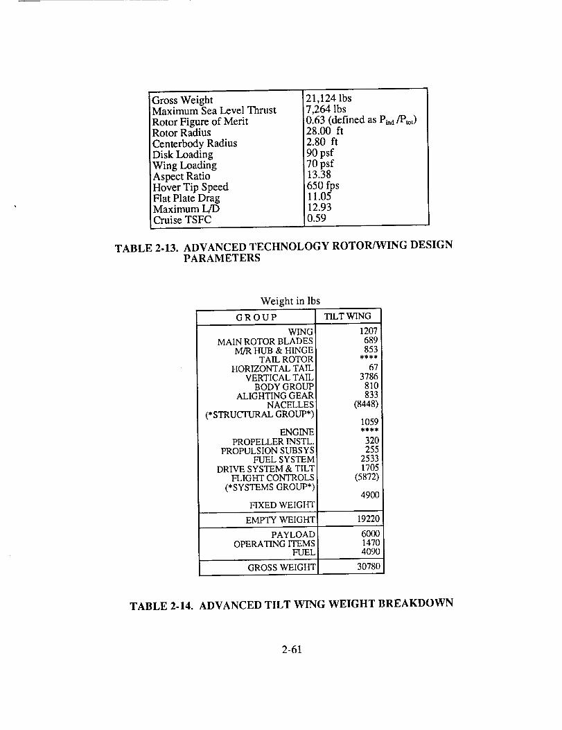
GrossWeightMaximumSeaLevelThrustRotorFigureof MeritRotorRadiusCenterbodyRadiusDisk LoadingWing LoadingAspectRatioHoverTip SpeedFlat PlateDragMaximumL/DCruiseTSFC
21,124lbs7,264lbs0.63(definedasPi,d/Ptot)28.00 ft2.80 ft90psf70psf13.38650fps11.0512.930.59
TABLE 2-13. ADVANCED TECHNOLOGY ROTOR/WING DESIGNPARAMETERS
Weight in lbs
G R O U P TILT WING
WINGMAIN ROTOR BLADES
M/R HUB & HINGETAIL ROTOR
HORIZONTAL TAILVERTICAL TAIL
BODY GROUPALIGHTING GEAR
NACELLES(*STRUCTURAL GROUP*)
ENGINEPROPELLER INSTL.
PROPULSION SUBSYSFUEL SYSTEM
DRIVE SYSTEM & TILTFLIGHT CONTROLS
(*SYSTEMS GROUP*)
1207689853
673786
810833
(8448)
1059
320255
25331705
(5872)
490OFIXED WEIGHT
EMPTY WEIGHT 19220
PAYLOAD 6000OPERATING ITEMS 1470
FUEL 4090
GROSS WEIGHT 30780
TABLE 2-14. ADVANCED TILT WING WEIGHT BREAKDOWN
2-61
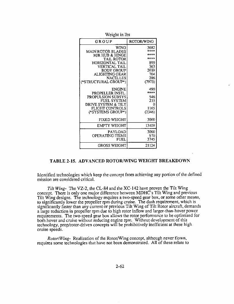
Weight in lbsG R O U P ROTOR/WING
WINGMAIN ROTOR BLADES
M/R HUB & HINGETAIL ROTOR
HORIZONTAL TAILVERTICAL TAIL
BODY GROUPALIGHTING GEAR
NACELLES(*STRUCTURAL GROUP*)
ENGINEPROPELLER INSTL.
PROPULSION SUBSYSFUEL SYSTEM
DRIVE SYSTEM & TILTFLIGHT CONTROLS
(*SYSTEMS GROUP*)
3682
899363
2039704286
(7973)
490
546235
01165
(2346)
30OOFIXED WEIGHT
EMPTY WEIGHT 13409
PAYLOAD 3000OPERATING ITEMS 970
FUEL 3745
GROSS WEIGHT 21124
TABLE 2-15. ADVANCED ROTOR/WING WEIGHT BREAKDOWN
Identified technologies which keep the concept from achieving any portion of the definedmission are considered critical.
Tilt Wing- The VZ-2, the CL-84 and the XC-142 have proven the Tilt Wingconcept. There is only one major difference between MDHC's Tilt Wing and previousTilt Wing designs. The technology requires a two-speed gear box, or some other means,to significantly lower the propeller rpm during cruise. The dash requirement, which issignificantly faster than any current or previous Tilt Wing of Tilt Rotor aircraft, demandsa large reduction in propeller rpm due to high rotor inflow and larger-than-hover powerrequirements. The two-speed gear box allows the rotor performance to be optimized forboth hover and cruise without reducing engine rpm. Without development of thistechnology, prop/rotor-driven concepts will be prohibitively inefficient at these highcruise speeds.
Rotor�Wing- Realization of the Rotor/Wing concept, although never flown,requires some technologies that have not been demonstrated. All of these relate to
2-62

conversion.TheRotor/Wingmaintainscontrolthroughuseof collectiveandcyclic pitchcontrol, anelevatorfor attitudecontrol,andvalvesfor diverting thegasfrom therotor tipto theengine.
Reductionof therotor inducedpitchandrolling momentsduringthefirst andlastfewrevolutionsof startingandstoppingtherotor hasbeendemonstratedduringmodelwindtunneltests. Regardlessof themeansusedto alleviatethis,cyclic pitch control tomaintain zero-lift on the rotor during conversion represents a critical technology.
During conversion, the hot gas must be diverted from the rotor tip jets to be used aspropulsive thrust. The gas diversion schedule which maintains the proper rotor rpm,while providing necessary propulsive thrust is critical to successful conversion.
Finally, a rigid, reaction-drive rotor, which incorporates cyclic pitch control, needs to befully investigated. Both the XV-9 and the XH-17 demonstrated the feasibility of reactiondrive rotors with cyclic pitch control. However, the need for fixed-wing flight puts anadded constraint on the Rotor/Wing. The XV-1 utilized a gimballed rotor that locked thegimballed degree of freedom in compound helicopter flight. The Rotor/Wing design willlock and stop in forward flight. The difference in rotor rigidity between these twoseemingly similar concepts may provide unforeseen problems in helicopter mode.
In any event, successful conversion of the Rotor/Wing without a critical technologyconvertible engine, dictates the use of a reaction-drive rotor system with cyclic control.This rotor must also have the ability to stop in forward flight (while fully unloaded) whilediverting the gas from the rotor tip to be used as propulsive thrust.
2-63


SECTION II1
ENABLING TECHNOLOGY PLAN


TECHNOLOGY DEVELOPMENT NEEDS
Introduction
This section assesses the technology development requirements for each of the two concepts.Each technology is described and its impact on vehicle effectiveness assessed. Since the studyemphasizes technology development needs, rather than the vehicles themselves, organization ofthe section is by technology discipline for ease in reference, then divided by vehicle type withinthe technology. Time lines provide an assessment of the major tasks within each technologydiscipline, and also identify the institutions best suited to accomplish a specified task. Finally, asummary table of technology development requirements for each concept and those which arecommon to both are identified, prioritized, and assessed for risk and payoff.
Aerodynamics
Technology Assessment- The following narrative explains the technological goals whichrequire attention to develop an efficient, high-speed Tilt Wing or Rotor/Wing concept.
The Tilt Wing concept flew successfully in several configurations, although it possessed asignificantly lower cruise speed than required here. The development of required technologiesreflects required improvements as opposed to critical technologies for this concept.
To fly at high-speed and at reasonable altitudes, the Tilt Wing requires development in twoareas. Efficient high-speed flight using rotors requires a design that provides goodpropulsive efficiencies at flight Mach numbers of .75 for lightly loaded rotors. Propellerdevelopment in the late 1950's achieved propulsive efficiencies of .8 during flight tests at flightMach numbers of .95 on thin-sectioned propellers. 24 These results indicate that the goal shouldbe achievable. Tip-speed reductions using a two-speed gear box or perhaps a variable diameterrotor reduce the compressibility effects due to the otherwise high tip-Mach number.Combinations of thin airfoils, planform design, and advanced configurations may provideimprovement in the high-speed efficiency.
The second area, development of airfoils with high drag-divergent Mach numbers, allows athicker, lighter weight wing which still provides a high-speed cruise capability. Theconfiguration allows only very slight wing sweep, so airfoil design alone must delay dragdivergence. The airfoil requirements will depend to a large extent on the structural design of thewing for minimum thickness. Hence, the drag divergence requirements may significantly ease ifthe wing can be made structurally thin. A thin wing is preferable to a thicker one because ofboth compressible and incompressible drag benefits, providing the stiffness requirements aremet.
Tilt Wing performance reflects a compromise between conversion characteristics and cruiserequirements. Past examples of the concept sacrificed cruise wing loading for reasonableconversion characteristics. This resulted in much more wing area than desired for efficient
cruise. Increasing cruise wing-loading would significantly improve cruise efficiency and wouldlead to greatly reduced gross weight. The literature repeatedly suggests that the use of high-liftsystems can reduce the area required of the wing for conversion. While certain chord todiameter ratios appear as limits, the aerodynamics suggests that the wing size required forconversion can be significantly reduced. Delaying the onset of wing stall and/or increasing thelift for a given angle of attack served as the basis for large wing areas on past tilt-wing
3-1
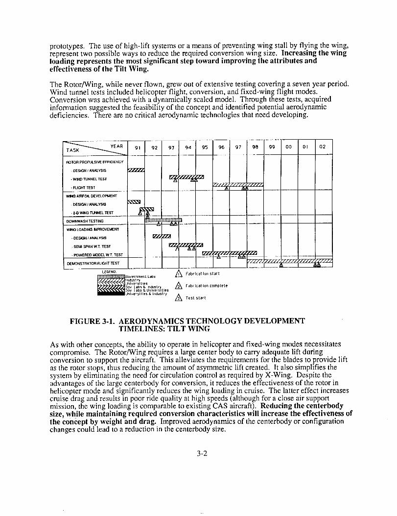
prototypes.Theuseof high-lift systemsor ameansof preventingwing stall by flying thewing,representtwo possiblewaysto reducetherequiredconversionwing size. Increasing thewingloading represents the most significant step toward improving the attributes andeffectiveness of the Tilt Wing.
The Rotor/Wing, while never flown, grew out of extensive testing covering a seven year period.Wind tunnel tests included helicopter flight, conversion, and fixed-wing flight modes.Conversion was achieved with a dynamically scaled model. Through these tests, acquiredinformation suggested the feasibility of the concept and identified potential aerodynamicdeficiencies. There are no critical aerodynamic technologies that need developing.
YEAR
TASK
ROTOR PROPULSIVE EFFICIENCY
- DESIGN / ANALYSIS
- WIND TUNNEL TEST
- FLIGHT TEST
WING AIRFOIL DEVELOPMENT
- DESIGN / ANALYSIS
• 2-D WIND TUNNEL TEST
DOWNWASH TESTING
WING LOADING IMPROVEMENT
- DESIGN I ANALYSIS
• SEMI-SPAN W,T. TEST
• POWERED MODEL W.T, TEST
DEMONSTRATOR FLIGHT TEST
LEGEND:
[ ll[IIJJJJlJJJJJJ.W G ov er r_m en t Labs
y_////,////A _ndus tryL"-.\\N\\\\NI On I v e rst t I e s
rflll/lll/IGov Labs & Industry_5ov Labs & Universities_l_lOnlversltles & Industry
91 92 93 94 95 96 97 98 99 O0 O1 02
//z/ZJ/////,/////-_
IZ_ Z22
r'//z_J/'/z///J///J
A Fabrication start
A Fabrication complete
A Test start
FIGURE 3-1. AERODYNAMICS TECHNOLOGY DEVELOPMENTTIMELINES: TILT WING
As with other concepts, the ability to operate in helicopter and fixed-wing modes necessitatescompromise. The Rotor/Wing requires a large center body to carry adequate lift duringconversion to support the aircraft. This alleviates the requirements for the blades to provide liftas the rotor stops, thus reducing the amount of asymmetric lift created. It also simplifies the
system by eliminating the need for circulation control as required by X-Wing. Despite theadvantages of the large centerbody for conversion, it reduces the effectiveness of the rotor inhelicopter mode and significantly reduces the wing loading in cruise. The latter effect increasescruise drag and results in poor ride quality at high speeds (although for a close air supportmission, the wing loading is comparable to existing CAS aircraft). Reducing the centerbodysize, while maintaining required conversion characteristics will increase the effectiveness ofthe concept by weight and drag. Improved aerodynamics of the centerbody or configurationchanges could lead to a reduction in the centerbody size.
3-2
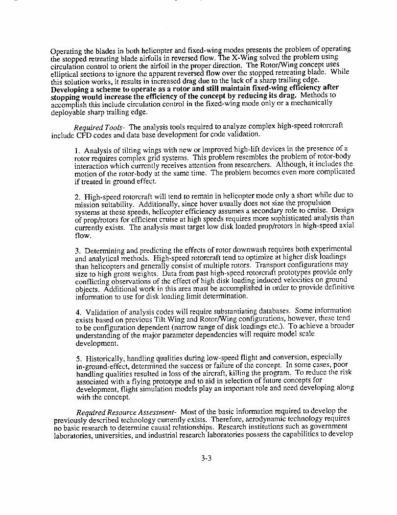
Operatingthebladesin bothhelicopterandfixed-wing modespresentstheproblemof operatingthe stopped retreating blade airfoils in reversed flow. The X-Wing solved the problem usingcirculation control to orient the airfoil in the proper direction. The Rotor/Wing concept useselliptical sections to ignore the apparent reversed flow over the stopped retreating blade. Whilethis solution works, it results in increased drag due to the lack of a sharp trailing edge.Developing a scheme to operate as a rotor and still maintain fixed-wing efficiency afterstopping would increase the efficiency of the concept by reducing its drag. Methods toaccomplish this include circulation control in the fixed-wing mode only or a mechanicallydeployable sharp trailing edge.
Required Tools- The analysis tools required to analyze complex high-speed rotorcraftinclude CFD codes and data base development for code validation.
1. Analysis of tilting wings with new or improved high-lift devices in the presence of arotor requires complex grid systems. This problem resembles the problem of rotor-bodyinteraction which currently receives attention from researchers. Although, it includes themotion of the rotor-body at the same time. The problem becomes even more complicatedif treated in ground effect.
2. High-speed rotorcraft will tend to remain in helicopter mode only a short while due tomission suitability. Additionally, since hover usually does not size the propulsionsystems at these speeds, helicopter efficiency assumes a secondary role to cruise. Designof prop/rotors for efficient cruise at high speeds requires more sophisticated analysis thancurrently exists. The analysis must target low disk loaded prop/rotors in high-speed axialflow.
3. Determining and predicting the effects of rotor downwash requires both experimentaland analytical methods. High-speed rotorcraft tend to optimize at higher disk loadingsthan helicopters and generally consist of multiple rotors. Transport configurations maysize to high gross weights. Data from past high-speed rotorcraft prototypes provide onlyconflicting observations of the effect of high disk loading induced velocities on groundobjects. Additional work in this area must be accomplished in order to provide definitiveinformation to use for disk loading limit determination.
4. Validation of analysis codes will require substantiating databases. Some informationexists based on previous Tilt Wing and Rotor/Wing configurations, however, these tendto be configuration dependent (narrow range of disk loadings etc.). To achieve a broaderunderstanding of the major parameter dependencies will require model scaledevelopment.
5. Historically, handling qualities during low-speed flight and conversion, especiallyin-ground-effect, determined the success or failure of the concept. In some cases, poorhandling qualities resulted in loss of the aircraft, killing the program. To reduce the riskassociated with a flying prototype and to aid in selection of future concepts fordevelopment, flight simulation models play an important role and need developing alongwith the concept.
Required Resource Assessment- Most of the basic information required to develop thepreviously described technology currently exists. Therefore, aerodynamic technology requiresno basic research to determine causal relationships. Research institutions such as governmentlaboratories, universities, and industrial research laboratories possess the capabilities to develop
3-3
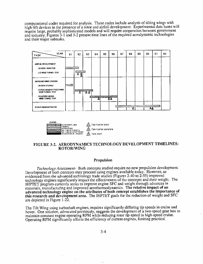
computationalcodesrequiredfor analysis.Thesecodesincludeanalysisof tilting wingswithhigh-lift devicesin thepresenceof arotor andairfoil development.Experimentaldatabaseswillrequirelarge,probablysophisticatedmodelsandwill requirecooperationbetweengovernmentandindustry.Figures3-1and3-2presenttime linesof therequiredaerodynamictechnologiesandtheirmajorsubtasks.
91 92 93 .94
AIRFOIL DEVELOPMENT
- DESIGN / ANALYSIS /////, //A
- 2-D WIND TUNNEL TEST _ _jr_
INCREASE WING LOADING --- I I
• DESIGN STUDIES
• FORCE-MOMENT FIXED WING r/l//,
WIND TUNNEL TEST
• POWERED MOOEL f/./'/j_ _//'/_,_,
wINO TUNNEL TEST t _/k
FLIGHT DEMONSTRATOR
95 96 I 97 98 99 I O0
I IOI 02
...... i
LEGEND:
(_/UJ_.I_ Gov er nme n t Labs
IndustryL\\\\\\\\N Un I v er s t t l e S
r.s////l.,r/ASov Labs & IndusVy_Gov Labs & UniversitiesIIIIIIUnlversltles & Industry
/_ Fabrication start
/_ Fabrication complete
A Test start
FIGURE 3-2. AERODYNAMICS TECHNOLOGY DEVELOPMENT TIMELINES:ROTOR/WING
Propulsion
Technology Assessment- Both concepts studied require no new propulsion development.Development of both concepts may proceed using engines available today. However, asevidenced from the advanced technology trade studies (Figures 2-40 to 2-55) improved
technology engines significantly imp.act the effectiveness of the concepts and their weight. TheIHPTET program currently seeks to improve engine SFC and weight through advances inmaterials, manufacturing and improved aerothermodynamics. The relative impact of anadvanced technology engine on the attributes of both concept establishes the importance ofthis research and development area. The IHPTET goals for the reduction of weight and SFC
are depicted in Figure 1-22.
The Tilt Wing using turboshaft engines, requires significantly differing tip speeds in cruise andhover. One solution, advocated previously, suggests the development of a two-speed gear box tomaintain constant engine operating RPM while reducing rotor tip-speed in high-speed cruise.Operating RPM significantly affects the efficiency of current engines, limiting practical
3-4
deviationfrom 100%.TheV-22 reducesengineRPM byabout80%in cruiseto reducerotortip-speedandmaintaingoodrotorpropulsiveefficiencies.However,high-speedflight, at400-450KTAS requirestip-speedreductionsof around50%,well below thatpracticalforcurrentengines.Thetwo-speedgearboxsolution,whileviable,addsweightcomplexityandincreasedmaintenancerequirements.Developmentof a turboshaft enginewhich operatesefficiently overa wide rangeof operating RPM could provide amuch better solution to thisproblem.
Thepropulsionrequirementsof theRotor/Wingvery significantly between hover and cruise.Hover requires engine exit conditions of high temperature And pressure ratios found with lowby-pass ratio engines (B.R. 1). This requirement, and the subsequent engine selection, results inless than optimal engine performance characteristics in cruise. This difference may not greatlyaffect a configuration designed for a short cruise duration mission, but it becomes increasinglyimportant for long range missions. Efficient cruise dictates using a high by-pass ratio engine.The extent to which these conflicting requirement can be resolved will influence the utility andeffectiveness of the concept. The IHPTET program, in seeking to improve SFC, targets some ofthe improvement through turbofan engines possessing the same engine exit conditions whileusing higher by-pass ratios. So, this program already seeks to resolve the conflictingrequirements previously addressed.
JTAGG Demo Program
Phase I
Phase II
Phase III
Turboshaft Demo Program
Phase I
Phase Jl
Phase III
gl g2 93 94 95
L////////////,'2"2'j
96 97 98 99
r/////H///////
!
O0 0! 02
_////////Y/Y/////_
Design And Fabrication
Testing Phase
FIGURE 3-3. IHPTET TIMELINE 14
Tip-turbine driven, ducted fans offer another way to improve cruise efficiency. This type of fan,demonstrated in the XV-5A, fan-in-wing, effectively increases the mass flow of ttie engine forgiven engine fuel flow rate, thus improving the overall efficiency of the propulsion system.Additionally, this means of propulsion maintains its drive system independence which makes it
3-5

soattractiveto beginwith. Quantifyingtheeffectivenessof this systemwill requiredetailedtradestudiesto examineefficiency,weight,installationconcernsandotheraspects.However,itrepresentsa viable,low-risk alternative.
Required Tools- Engine development programs such as IHPTET are in place withtechnology goals as previously described. The participating engine manufacturers defined theresources required to include development of advanced computer predictive codes, experimentalmaterials programs, and configuration design. Further coordination between airframe companiesand engine companies will help define the impact of the IHPTET goals to specific applicationsand identify specific, possibly, unique engine requirements. Detailed discussion of specific toolsrequired is deferred to IHPTET program documentation.
Required Resource Assessment- Successful completion of the IHPTET program willincorporate cooperative efforts from all the major institutions. Basic research into materialsproperties development of new materials and analysis methods should grow out of efforts atuniversities and government laboratories from requirements generated by industry. Closeassociation between government and industry will lead to application in the form of enginetechnology demonstrators. Resources from both of these institutions will be needed to develop,test, and demonstrate the new technology. Engine test facilities and possibly flightdemonstrators, as accomplished with propfan development, will improve chances for success.Figure 3-3 depicts the timeline of major IHPTET tasks, culminating in a technologydemonstrator by 2003.
Drive Systems
Technology Assessment- The drive systems proposed for the Rotor/Wing and Tilt Wing
are proven concepts and are feasible using present technology.. The jump from technicalfeasibility to economic practicality will require improvements m both systems.
Rotor/Wing: Relatively long runs and sharp turns in the Rotor/Wing ducting cause asignificant stagnation pressure loss due to viscous effects and thermal losses. Internal flowcharacteristics and optimized designs must receive further investigation in order to reducepressure losses throughout the system and identify potential thermal "hot spots", Improvementsin the surface condition and contouring of the ducts will minimize viscous effects, whileapplication of materials with low thermal conductivity and thermally reflective coatingspromises to reduce thermal losses.
Previous designs used metal ducts hard mounted to the aircraft structure. This easedmanufacturing and provided some thermal isolation for the structure, but was a heavy solution.The ability to manufacture ducts integrally within the structure would provide significant weightsavings. This will require development of new manufacturing techniques to produce hollowstructures capable of withstanding the high temperatures and having suitable insulatingproperties and surface conditions.
Metal matrix composites exist which meet or exceed the 1050 deg. F temperature requirementsfor Rotor/Wing ducting, z5 Economical manufacturing processes must be developed to makethese materials an affordable option. Thermal barrier coatings on conventional composites
(graphite, fiberglass) provide a promising, alternative. These coatings demonstrate goodinsulative and corrosion resistive propemes in similar applications. Economical and consistent
application techniques require further development.
3-6

TheRotor/Wingductingsystemusesthreetypesof exhaustseals:onein thedivertervalves,onein themast,andoneat eachof thebladeroots(seeFigure2-29). TheAV-8B usessimilar sealsin its hot gasductingsystem,sothisdoesnotrepresentacritical technology.Therotating-troughdivertervalveproposedfor theRotor/Wingdifferssignificantlyfrom theturning-vanetypeusedonpastdesigns(Figure3-4). Thisproposedvalvefeaturesequallyefficient operationin bothdiversiondirections. Researchwill benecessary,however,to optimizethegeometryto reducelossesat intermediatepositionsof thetrough.
TO PROPULSIVETHRUST NOZZLE
TROUGH AXISOF ROTATION
ROTATING TROUGH
FROM ///ENGINE
TO MAST
FIGURE 3-4. ROTOR/WING DIVERTER VALVE
Tip-jet geometry has a great deal of potential for optimization. Turning vane spacing, crosssections, and locations are topics that will require further investigation. Jet exit area will need tobe controlled based on the pressure and mass flow rate through the duct, especially during OEIsituations. A simple system would actuate all three blades simultaneously based on the massflow rate through the mast. A shutter would vary from closed in forward flight to fully open atmax power hover. A more complex approach would cyclically control each shutterindependently to maintain fully expanded flow through the entire 360 deg. travel of the blade.This would require an actuator that could operate in a high-G environment at a frequency of1/rev. The actuator would most likely have to be electrically powered because of its location inthe rotor.
Tilt Wing: The Tilt Wing drive system utilizes a conventional transmission with atwo-speed capability. The success of the Tilt Wing as a transport or cargo aircraft will bedetermined by its cost effectiveness. It is essential that the drive system weight and reliability beimproved from present standards to improve its chances of acceptance in the market. TheAdvanced Rotorcraft Transmission (ART) program, currently under way at MDHC to enhancethe performance of rotorcraft transmissions, is investigating many technologies to meet thisobjective.
3-7

New geartoothforms,underdevelopment,offer higherloadcarryingcapabilitiesthanthosecurrentlyin service.Corrosionandwearsurfacetreatmentsarebeinginvestigatedwhichincreasescoringresistance.Roughforgingof gearteethimprovesthepotentialstrengthofnonforgedteethby a factorof five. All thesewill leadto smaller,lighter gearscapableofcarryinghigherloads.
New bearingtypesandlubesystemspromiseto reducecostandincreaselife. Self aligningsphericalroller bearingscanloosentolerancerequirementsreducingmanufacturingcosts.
Shaftswith integralbearingraceseliminatetheweightof pressedin races.Advancedoil lubesystemsandevengreasegearlubricationpromisereducedwearandimprovedreliability.
DRIVE TRAIN
91 92 93 94 95 96 97 98 99 O0 OI 02
GEARS
DESIGN / ANALYSIS
TEST P77 z77-A
BEARINGS
DESIGN / ANALYSIS
TEST
Z3P77 77"_
2 SPEED CONCEPTS
DESIGN I ANALYSIS
TEST
y////l/////
LEGEND:
lllI[llllHllllllllGovernment LabsL/////////] IndUS tryr,.\\\\\X\\lUnlv e r s I t Ie S
V////////J Gov Labs & Industry_GOW Labs & Universities
WlIJlllmMmlJIUnlvers.ltles & industry
/_ FABRICATION START
_ FABRICATION COHPLETE
A TEST START
FIGURE 3-5. DRIVE SYSTEMS TECHNOLOGY DEVELOPMENT TIMELINES:TILT WING
Various overrunning and positive engagement clutches for disengaging shut down engines areunder development to reduce weight and extend life. Rotor tip-speed limitations to maintainpropulsive efficiency require nearly a 2:1 ratio between hover and cruise rpm. A shiftabletwo-speed transmission, extending the concepts used in automobile automatic transmissions, isthe most feasible solution. It is critical that disk and band clutches for a transmission of this type
be developed which can handle the torques and speeds found in the Tilt Wing.
3-8

9192 93 94 95 96 97 98 99 00 01 02
HOTGAS DUCTING
DUCT FAB. TECHNIQUES
COATING APPLICATION 7-_J"l////_'//////////J ._
I,_ I'_ I IHIGH TEMP COMPOSITES /.,,,,/_/.i)l/lll_,/jr/./#,__
A ,/_ A
DIVERTERVALVE
DESIGN / ANALYSIS
TEST
TIP JET
DESIGN/ ANALYSIS _Z_
LEGEND:
_Government Labs _ FABRICATION :STARTL/////////31 ndus t r y /,_Unlvers_tles
//2\ FABRICATION COMPLETEV/////,///A Gov Labs & Industry_Gov. Labs & Universities A
_IUnlversRles & Industry _ TEST 5TART
FIGURE 3-6. DRIVE SYSTEMS TECHNOLOGY DEVELOPMENT TIMELINES:ROTOR/WING
Required Tools-
1. Computer programs currently available optimize the size of a given tooth combinationor reduction configuration but do not allow comparison of different configurations. Sizingof gearboxes will require optimization routines that process discrete variables, such asnumber of gearboxes or reduction stages, effectively.
2. Integration of drive train sizing programs with conceptual level CAD programs togenerate solid models from sizing program output require development. 3-D models areinvaluable in evaluating the feasibility of configurations because they illustrateinconsistencies which present analysis codes are unable to identify. The time required togenerate a solid model with any degree of complexity prohibits the number of iterationswhich would be desirable. Quite often the final configuration of a subsystem is determinedearly in the design process. However, the specific parameters of the system changecontinually. Software must be developed to generate the specific geometric entities withinthe CAD model based on parameters from sizing codes.
3. Subsystems of the future need to be evaluated based on their contribution to the aircraftlife cycle cost. Life-cycle cost databases need to be established and relationshipsdeveloped for all the aircraft subsystems.
3-9

4. Testingreactiondrive systemswill requirebuilding full scaleteststands.Testingwillallow developmentof experimentaldatabasesandpossibleparametervariationin whichtooptimizetheductsystem.
Required Resource Assessment- As a result of theoretical relationships that have alreadybeen established for the technologies previously described, no basic research is required. Thereis, however, a need for fabrication and testing of component hardware to validate design
concepts and develop efficient/affordable manufacturing techniques. Industrial research labspossess the capabilities to build and test components under development. Figures 3-5 and 3-6show development timelines in the drive system technology areas.
Structures
Technology Assessment- Significant advances in the technology areas of structures andmaterials will be required to help meet the performance goals of high- speed rotorcraft.
The primary requirement will be to develop thin rotor and wing structures to reduce aerodynamicdrag and attain high drag-divergent Mach numbers. Typically, these structural designs will bedriven by either a stiffness or a strength requirement. The judicious application of compositematerials in the rotor and wing structures of hlgh-speed rotorcraft is essential in order tomeet the design requirements.
Improvements in the stiffness and strength of composite materials will facilitate the developmentof rotor and wing structures for the high-speed rotorcraft. Specifically, the development ofhigher modulus fibers and increases in the transverse strength of composite materials arerequired.
Higher modulus composites are necessary to help meet stiffness requirements with thin wingstructures. This is particularly important if aeroelastic stability considerations greatly influencethe design requirements.
Composite materials suffer from low strength transverse to the fibers. This leads to significantmatrix cracking and delamination in many composite structural designs. Improvements in basicmaterials processing technology and materials development are required to minimize thisundesirable characteristic. Enhancements in materials and processing include the developmentof higher strength matrix materials and improved fiber-matrix interfacial bonding. In addition,the evolution of new composite material architectures such as three-dimensional weaves andstitched preforms will lead to increased delamination resistance.
Optimal use of composite materials in structural designs for high-speed rotorcraft must beexercised to meet the design goals. Composite materials are often applied in structural designswith a "metals philosophy", i.e., a limited selection of layups (typically quasi-isotropic) are usedfor which properties are well known. This is done primarily to reduce analysis costs and developa focused data base for the design methodology. However, this approach limits the potential forweight savings in the design by providing redundant structure for the load requirements.
3-10

Composite structures for high-speed rotorcraft must be tailored to carry the necessaryloads and provide adequate stiffness to meet aeroelastic constraints. Weight savings arecritical to the successful development of these rotorcraft and will be maximized using thisapproach. In addition, the development of thin rotor and wing structures will be more feasiblewith the increased design flexibility.
Technology for the manufacture of composite structures will need refinement in order toreduce fabrication costs and improve reproducibility. Thermoplastic composite materialsoffer numerous novel approaches for fabrication which will require continued development forfull-scale production.
Required Tools- Extensive analysis capabilities will be required to examine the stiffnessand strength of candidate structural designs.
1. The different stiffnesses and structural coupling effects associated with compositestructures must be appropriately modeled to assess stiffness characteristics for aeroelasticconsiderations. This establishes a requirement for efficient analytical techniques tomodel the response of composite rotor and wing structures to aerodynamic loads.Advanced finite element modeling techniques provide a comprehensive means ofinvestigating this problem.
2. The failure analysis of composite structures is a difficult task to accomplish. Severalreasons contribute to this: (1) modeling the variation of material properties in theindividual plies is a formidable effort, (2) accounting for changes in the structuralgeometry of complex composite structures (eg., stiffeners joined to a wing) presents achallenge, and (3) interlaminar stresses often promote the failure of composite structuresand must be analyzed. Thus, advanced three-dimensional modeling techniques arenecessary to assess the strength and damage tolerance of candidate composite structuresfor high-speed rotorcraft.
3. A great deal of scatter (relative to metallic materials) is associated with the strengths ofcomposite materials. Since a number of strength parameters (associated with differentfailure modes) exist for composites, structural reliability calculations become quiteextensive. Probabilistic analysis methods need to be developed and applied for thereliability assessment of composite structural designs.
4. Databases will have to be created to validate the composite structural analysis codesdeveloped. This includes coupon and component tests of representative rotor and wingstructures to assess stiffness and strength prediction capabilities. Duplication of full-scalefailure modes at this level of testing is mandatory.
Required Resource Assessment- Basic research to improve the stiffness and transversestrength characteristics associated with composite materials is required. Primarily governmentlaboratories and universities should be tasked with this effort. However, the materials industrymay also play a role. Universities and the aerospace industry will need to work closely todevelop advanced finite element techniques for composite structural analysis. In addition,methodologies for probabilistic analysis of composite structures require attention. Bothuniversities and industry need to contribute to the creation of a composite structures data base for
3-11

high-speedrotorcraft. Industrywill bechallengedwith thedevelopmentof provenmanufacturingconceptsfor rotor andwing structures.Thedevelopmentschedulefor structurestechnologyisShownin Figure3-7.
91 92 g3 94 95 96 97 98 99 O0 OI 02
COMPOSITE MAITR_LS
- HIGHER I/DDULUS_STRENO1rH
• FIBEPaldATRIX INTERFACE
- _10 ARCHITECTURES
COMPOSITE FINITE ELEMENT
ANALYSES
- FE RESPONSE I_OELS
- 3D FE FAILURE MODELS
PROBABILISTIC MODELS
COMPOSITE STRUCTURES DATA
BASE
- COUPONS
- COMPONENTS
7_JT_!_lllllllillllllJ,
LE6END:
Government Labs
IndustryUniversities
Gov Labs & InduStry5ov Labs & Universities
Universities & IndustryGov Labs & Industry &
Universities
FIGURE 3-7. STRUCTURES TECHNOLOGY DEVELOPMENT TIMELINES
Stability and Control
Technology Assessment- No critical technology needs developing in this area for eitherconcept. Both concepts would benefit by incorporating active controls, The use of afly-by-wire control system allows this option. Active controls would reduce empennage area,thus reducing weight and drag. The effect of this addition, as previously depicted in Figure 2-49,produces only small increases in concept effectiveness. The Rotor/Wing would probably benefitthe most from active controls due to the inherently unstable configuration in airplane mode.Additionally, as previously demonstrated through wind tunnel tests in the mid 1960's 7 elevon
deflection, during rotor stopping and starting, could provide a means to counter the short termpitch and roll oscillation experienced by the aircraft due to any asymmetric lift produced by therotor.
Past Tilt Wing configurations experienced reduced yaw control in-ground-effect due to thereduced effectiveness of the wings in close proximity to the ground. The use of spoilersimproved the yaw control by killing the wing lift on one side of the aircraft. 22 Us|ng roiorcontrols such as differential cyclic would improve the yaw control characteristics in all regimes
3-12

of helicopterflight. Thispresentsamorecomplicatedhubarrangementandrequiresnewcontrollaw developmentoverpreviousTilt Wing demonstrators,butwouldsignificantlyimprovethelow-speedflight characteristics.
Similarly,cyclic controlcouldreplacetheneedfor thepitch fanof previousdesigns.Thepitchfan addedweight,complexityanddragto previousTilt Wings. Pitchcontrol,throughlongitudinalcyclic, would improvetheoveralleffectivenessof theconcept.Trade studies,comparing the benefitsof cyclic control against the disadvantagesmust first be initiated.Developmentof this technologyrequireslittle risk, asit duplicatestechnologyin placefor theV-22 andXV- 15.
YEARTASK _ 91 92 93 94 95 96 97 98 99 O0
_.- .,
SYSTEM TRADE STUDIES
O1 02
SIMULATION
- DYNAMIC MODEL r-//fJJ if/'/.//-.///,]
DEVELOPMENT _,r# -/j_///, / 7_- SIMULATION DEVELOPMENT
POWERED MODEL
WIND TUNNEL TEST
R / G MODEL PROGRAM //
6 AA
LEGEND:
Government LabsIndustry
_._.,_Unlversltles
V/JJ//fJ/JG0v Labs & Industry_Gov Labs & Universities
_B_l/Unlversttles & Industry
/_ Fabrication start
//_ Fabrication complete
A Test start
FIGURE 3-8. STABILITY AND CONTROL TECHNOLOGY DEVELOPMENTTIMELINE: TILT WING
Control of the Rotor/Wing in helicopter mode requires use of standard helicopter type controlsfor roll and pitch. Control moments result from cyclic inputs to the rotor. Yaw control systemswill be conventional in control, but evaluation of several concepts for yaw control will be
required. Possible configurations include a hydraulically driven tail fan as suggested in early rM1960 s design studies, an electrically driven tail fan, or a thruster such as found in the NOTARsystem. Since the yaw control system requires little power (no anti-torque requirements), the
3-13

systemneednot beexcessivelylarge. Selection of the appropriate yaw control systemrequires additional design and trade studies but little in the way of technology
development.
Lateral control of the Rotor/Wing in airplane mode presents a more challenging problem.Previous studies envisioned the use of elevons for lateral control. Wind tunnel tests indicated
that the outboard wing panels (blades) could not provide the required control moment whendeflected due to flow off the centerbody (aft swept configuration). The forward sweptconfiguration alleviates this problem but may introduce structural divergence or flutter if theouter panels are deflected at high speed. Development of an effective lateral control systemwill require technical solutions from aerodynamics, structures and avionics areas.
91 92 93 94 95 96 97 98 99 00 01
sYSTEM DESIGN I TRADE STUDIES
FORCE-MOMENT FIXED WING _//'/_ _//1"/_TEST (lATERAL CONTROL) /_ ,_k A
II_WERED MOOEL W.T. TEST
MOOEL PROGRAM
Jt'Jl'_¢l, ¢l'J'J'J'l_ rJl_vJ_
I/
O2
SIMULATION
. DYNAMIC MODEL OEV,
. SIMULATION DEV.
_',P'///# fi///# f/A
r/_/_Z ZZZ/Z cA
LEGEND:
I IIIIII1 IIIIIIIIIIIIGovernm ent LabsL.,'////////l_ndustryr',,x\\\\\\\l Unlye rst t leSy/i/I////JGov Labs & Industry_Gov. Labs & Universities_Untversltles & Industry
A Fabrication start
_ Fabrication complete
A Teststart
FIGURE 3-9. STABILITY AND CONTROL TECHNOLOGY DEVELOPMENTTIMELINE: ROTOR/WING
Required Tools-
1. For both concepts, flight simulation models will significantly aid development ofcontrol laws and in assessing effectiveness of the control systems in all flight modes.
2. Wing tunnel testing must provide important stability and control data for modeling.Testing can be accomplished in existing tunnels.
3. Development of radio controlled models to identify stability and control problems willprovide a valuable tool. These models will also provide an inexpensive flight vehicle totry out control system concepts.
3-14
Required Resource Assessment- Technology development in this area will rest largely
with industry, while government laboratories and resources, and universities will play asupporting, cooperative role. Large-scale wind tunnel models require the use of governmentwind tunnel facilities to obtain data. Small scale radio controlled model work may best beaccomplished with university support. Simulation development and use would most effectivelybe accomplished by cooperative industry/government laboratory initiatives. The followingfigures depict timelines required to develop effective stability and control systems.
Control Systems
Technology Assessment- Today's control system technology is sufficiently advanced tomeet the needs of the Tilt Wing and Rotor/Wing. There are, however, several areas ofdevelopment that offer worthwhile improvements.
Self contained pump/actuator packages which eliminate the need for centralized pumps,accumulators, and hydraulic lines are becoming available. These units are self-contained andindependent, therefore, damage to one will not degrade or stop performance of the others. Powercan be supplied electrically or mechanically. Further development and testing remains to bedone prior to system final design.
Digital fly-by-wire control systems are becoming more and more common as their cost andreliability improve. Presently, fly-by-wire systems utilize three independent computers for tripleredundancy, and a mechanical or analog electrical backup in case of EMI. Improvements incomputer reliability and system survivability may eliminate the need for one or even two of thebackup computers, reducing weight and complexity.
The mechanical and electrical backup systems are good candidates for replacement. Electricalbackups are susceptible to electrical system failure and mechanical systems are weightprohibitive. Fly-by-light and reduced sensitivity to EMI may eliminate the need for thesesystems. In the mean time, the emergence of fluidic control circuitry provides a nonelectrical,light weight alternative for backup control. Input signals are transmitted through very small,light weight hydraulic (or pneumatic) lines to the controller whose logic is processedhydraulically (or pneumatically).
Required Tools-
1. Integrated pump/actuator packages need to be certified for use on aircraft. This willrequire test stands for system evaluation and, ultimately, flight testing.
2. Elimination of any redundancy in the digital control system must be justified bydemonstrating acceptable reliability of the remaining components. This will requireenvironmental chambers and vibration test equipment to simulate worst case operatingconditions. These simulations will enable identification of and reduction of failure modes
and will provide an accurate measure of system reliability.
3. Software must be developed to expedite the analysis and design of fluidic circuits.Circuits must then be built and tested in a "brass board" fashion to validate the software.
3-15

4, Developmentandcertificationof fluidic backupcontrolsystemswill requireacquisitionof componentpartsfrom thevendorandlaboratoryspacein whichto conductexperiments.Vendorconsultingwill alsobenecessary.
5. Simulatorswill beneededto evaluatethecontrollawsandcockpitintegration.
Required Resource Assessment- The theoretical relationships have already beenestablished for the technologies described, therefore, no basic research is required. There is aneed for adaptation and testing of new products that are becoming available for use on aircraft.Industrial research labs possess the capabilities to develop and certify commercial hardware.The development timeline shown in Figure 3-10 depicts the control system technology areaswith their major milestones.
YEAR
DESIGN
TEST
LAB SET-UP
COMPONENTTESTS
FLUIDICS
SOFTWARE
HARDWARETEST
9]
Zd
721
LEGEND:
6overnment LabsIndustry
_UnlversltiesVlllllllI, J_ov Labs & In(_u_try_5ov Labs & Unwersltlls_Unlversltles 8, Industry
94 95 I 96 I 97
"////1 ////////1//,
A FADRICATION START
/_ FABRICATION COMPLETE
A TEST START
..F I I
98 99 O0 I 0l 02
I
FIGURE 3-10. CONTROL SYSTEMS TECHNOLOGY DEVELOPMENTTIMELINES.
Dynamics
Technology Assessment- The discussion which follows addresses the technologies thatwill be required to develop Tilt Wing or Rotor/Wing aircraft capable of efficient, safe operations.Since the Tilt Wing concept has been flown in several configurations, the feasibility of theconcept is not in question. The question that must be addressed is whether a Tilt Wing aircraftcan be designed to achieve high-speed flight. The Rotor/Wing concept, on the other hand, hasnot flown. However, extensive wind tunnel testing of a rotor/wing concept was carried out in the
3-16
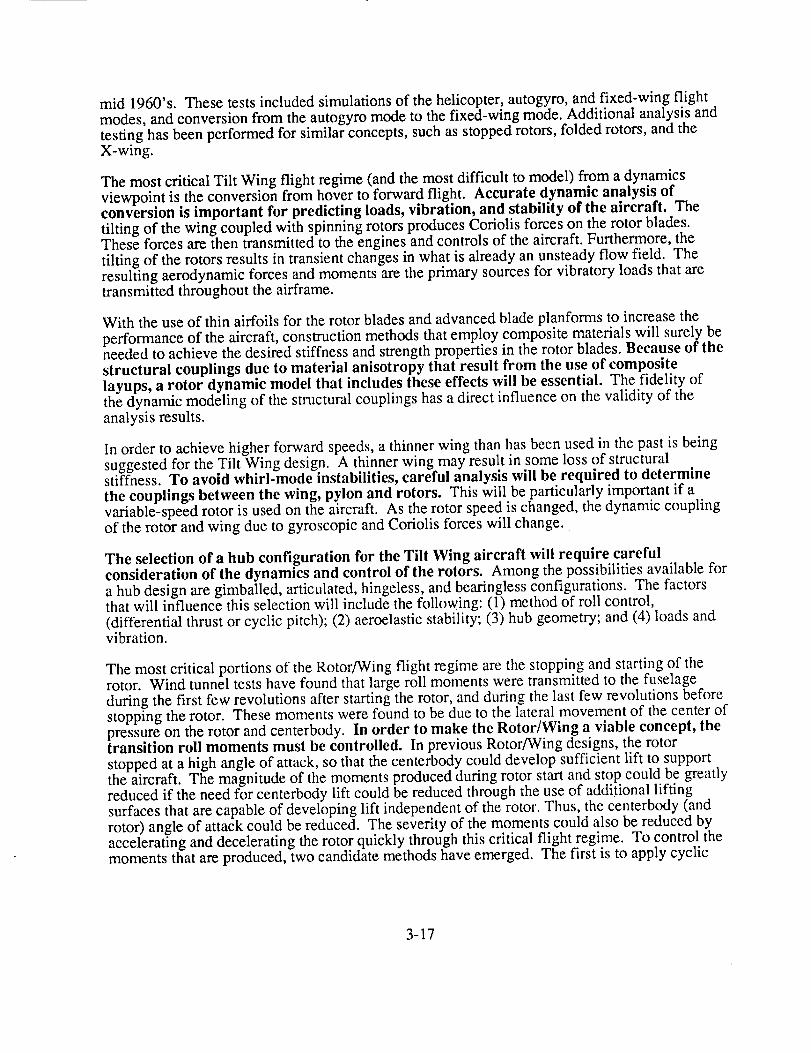
mid 1960's. These tests included simulations of the helicopter, autogyro, and fixed-wing flightmodes, and conversion from the autogyro mode to the fixed-wing mode. Additional analysis andtesting has been performed for similar concepts, such as stopped rotors, folded rotors, and theX-wing.
The most critical Tilt Wing flight regime (and the most difficult to model) from a dynamicsviewpoint is the conversion from hover to forward flight. Accurate dynamic analysis ofconversion is important for predicting loads, vibration, and stability of the aircraft. Thetilting of the wing coupled with spinning rotors produces Coriolis forces on the rotor blades.These forces are then transmitted to the engines and controls of the aircraft. Furthermore, thetilting of the rotors results in transient changes in what is already an unsteady flow field. Theresulting aerodynamic forces and moments are the primary sources for vibratory loads that aretransmitted throughout the airframe.
With the use of thin airfoils for the rotor blades and advanced blade planforms to increase theperformance of the aircraft, construction methods that employ composite materials will surely beneeded to achieve the desired stiffness and strength properties in the rotor blades. Because of thestructural couplings due to material anisotropy that result from the use of compositelayups, a rotor dynamic model that includes these effects will be essential. The fidelity ofthe dynamic modeling of the structural couplings has a direct influence on the validity of theanalysis results.
In order to achieve higher forward speeds, a thinner wing than has been used in the past is beingsuggested for the Tilt Wing design. A thinner wing may result in some loss of structuralstiffness. To avoid whirl-mode instabilities, careful analysis will be required to determinethe couplings between the wing, pylon and rotors. This will be particularly important if avariable-speed rotor is used on the aircraft. As the rotor speed is changed, the dynamic couplingof the rotor and wing due to gyroscopic and Coriolis forces will change.
The selection of a hub configuration for the Tilt Wing aircraft will require carefulconsideration of the dynamics and control of the rotors. Among the possibilities available fora hub design are gimballed, articulated, hingeless, and bearingless configurations. The factorsthat will influence this selection will include the following: (1) method of roll control,(differential thrust or cyclic pitch); (2) aeroelastic stability; (3) hub geometry; and (4) loads andvibration.
The most critical portions of the Rotor/Wing flight regime are the stopping and starting of therotor. Wind tunnel tests have found that large roll moments were transmitted to the fuselageduring the first few revolutions after starting the rotor, and during the last few revolutions beforestopping the rotor. These moments were found to be due to the lateral movement of the center ofpressure on the rotor and centerbody. In order to make the Rotor/Wing a viable concept, thetransition roll moments must be controlled. In previous Rotor/Wing designs, the rotorstopped at a high angle of attack, so that the centerbody could develop sufficient lift to supportthe aircraft. The magnitude of the moments produced during rotor start and stop could be greatlyreduced if the need for centerbody lift could be reduced through the use of additional liftingsurfaces that are capable of developing lift independent of the rotor. Thus, the centerbody (androtor) angle of attack could be reduced. The severity of the moments could also be reduced byaccelerating and decelerating the rotor quickly through this critical flight regime. To control themoments that are produced, two candidate methods have emerged. The first is to apply cyclic
3-17
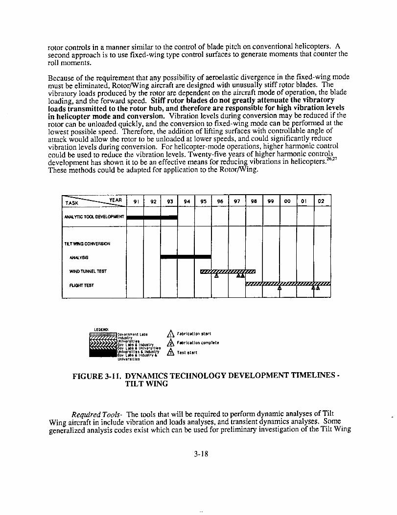
rotor controlsin a mannersimilar to thecontrolof bladepitchonconventionalhelicopters.Asecondapproachis to usefixed-wing typecontrolsurfacesto generatemomentsthatcountertheroll moments.
Becauseof therequirementthatanypossibilityof aeroelasticdivergencein thefixed-wing modemustbeeliminated,Rotor/Wingaircraftaredesignedwith unusuallystiff rotor blades.Thevibratoryloadsproducedby therotoraredependenton theaircraftmodeof operation,thebladeloading,andtheforward speed.Stiff rotor bladesdonot greatly attenuatethe vibratoryloadstransmitted to the rotor hub, and therefore are responsiblefor high vibration levelsin helicopter modeand conversion. Vibration levelsduringconversionmaybereducedif therotor canbeunloadedquickly, andtheconversionto fixed-wingmodecanbeperformedat thelowestpossiblespeed.Therefore,theadditionof lifting surfaceswith controllableangleofattackwouldallow therotor to beunloadedatlowerspeeds,andcouldsignificantlyreducevibrationlevelsduringconversion.For helicopter-modeoperations,higherharmoniccontrolcouldbeusedto reducethevibrationlevels.Twenty-fiveyearsof higherharmoniccontrolsdevelopmenthasshownit to beaneffectivemeansfor reducingvibrationsin helicopters)6'27Thesemethodscouldbeadaptedfor applicationto theRotor/Wing.
91 92 93 94 95 96 97
ANALYTICTOOL DEVELOPMENT
98 99 O0 Ol 02
TLT WING CONVERSION
ANALYSIS
WIND TUNNELTEST
FLIGHTTEST
JrfJL, ,fJJfJ ,'JJJJJ fJJJ
AA
LEGEND:
Government Lebs
I_str_Unlversltlel
_v L_s & l.n_. St_5ov, LataS & unlvtr$1tle!
lVer_,ltles I, JNv'JtrYv LIOI /L JnOgl|ry &
Universities
A Fabrication start
A FaOrlcstlon ¢;ornplete
A Test start
FIGURE 3-11. DYNAMICS TECHNOLOGY DEVELOPMENT TIMELINES .TILT WING
Required Tools- The tools that will be required to perform dynamic analyses of Tilt
Wing aircraft in include vibration and loads analyses, and transient dynamics analyses. Somegeneralized analysis codes exist which can be used for preliminary investigation of the Tilt Wing
3-18

andRotor/Wingconcepts,andasbasesfor developmentof morerobustcodes.In addition,analysisof flight testandwind tunneltestdatafrom previousTilt Wing andRotor/Wingdesignsis requiredto validatetheresultsgeneratedby thedynamicanalyses.
1. Analysisof thetransitionfrom hoverto forwardflight (andback)will requireimprovedanalysiscodesthatincludetheeffectsof rotor-fuselageinteractions.Theanalysesmustalsomodeltheaeroelasticbehaviorandrotor-fuselageinterferenceof acoupledrotor andfuselageathighrotor anglesof attack.Existing helicopteranalysesdonothandlethetransientdynamicsof conversion,andexistingmultibodydynamicscodescanadequatelymodeneitherflexible structuresnor theaerodynamicenvironment.Theaeroelasticbehaviorof thetip-jet drivenrotorsmustalsobeconsideredfor theRotor/Wing. Tip jets changethestructuralbehaviorof therotorby eliminatingtheusuallaggingmomentandchord-wiseshearat thebladeroot. Also, therotorwakemaybesignificantlyaffectedby theinjectionof jet gassesfrom thebladetip.
2. Safeoperationof Tilt Wing andRotor/Wingaircraftwill requirethedevelopmentofcontrol algorithmsandhardwarefor conversionfrom hoverto forwardflight. Thecontrolscouldinvolvemanycombinationsof both low andhigh-frequencycontrolofrotor bladepitchandfixedcontrolsurfaces,in additionto attitudecontrol.
3. In orderto validatetheanalysismethodsdevelopedfor Tilt WingandRotor/Wingaircraft,datafrom wind tunnelandflight testsmustbecollectedandcatalogedsuchthatit is usefulfor correlationwork. All availabledatafrom flight anddevelopmenttestingoftheVertol VZ-2, theHiller XH-18, the LTV XC-142A, and the Canadair CL-84 could be
put into a database, which could then be drawn upon as necessary. Similarly, the windtunnel data from the extensive Rotor/Wing tests should be collected.
4. Results from previous testing may not provide full coverage of all the technologyareas required for the development of a high-speed Tilt Wing or Rotor/Wing aircraft.The lack of coverage may be a result of insufficient testing of the earlier concepts andaircraft, or a result of the infusion of new technology into the design. In either case,dynamic model tests should be undertaken to fill in the experience base, provide insightinto specific configurations, and provide analyst and designer alike with a basis on whichto make sound engineering judgements.
Required Resource Assessment- As evidenced by the existence of Tilt Wing aircraft, thetechnology required to design and build such an aircraft is available. However, in order to meetthe mission requirements, the technology must be upgraded such that an aircraft can be createdwhich can achieve those requirements. Similarly, analyses and databases sufficient forpreliminary investigations of the Rotor/Wing concept already exist. However, more detailedanalysis and testing are required. Most research institutions, whether in academia, government,or industry, possess the capability of modifying or creating the computational tools necessary toanalyze the dynamics of Tilt Wing and Rotor/Wing aircraft. The government is an obviouschoice to coordinate the collection of test data. There would be fewer constraints on them
relative to proprietary rights and other privacy issues than on universities or industry.
3-19

Furthermore,thegovernmenthasthefacilities to disseminatethedataasnecessary,on awiderscale.Universitiescould,however,assistin thecreationof thedatabasesfor thetestdata.Testin_couldmosteasilybedonejointly by thegovernmentandindustry,with thegovernmentproviding thetestfacilities andindustryprovidingthemodels.Figures3-11and3-12showtimelinesrequiredto developrequiredtechnology.
YEAR 02TA5K __._ 91 92 93 94 95 96 97 98 99 O0 OI
ROTOR / WING CONVERSION
ANALYSIS
WIND TUNNEL TEST
FLIGHT TEST
[ "////I "llllL ¢JJJl_
__1]]1]J]1111111111111"]
I I'1
LESEND:
FIGURE 3-12.
Government LabsIndustryUniversities6ov Labs & InaustryGov, Labs & UniversitiesUniversities & IndustryGov Labs & InduStry &Universities
,_Fabrtcatton start
Fabrlcatlon complete
A Test start
DYNAMICS TECHNOLOGY DEVELOPMENT TIMELINES -ROTOR/WING
Summary
Two concepts, the Tilt Wing and the Rotor/Wing, were chosen for additional study beyond theTask 1 requirements. These concepts represented low and high risk respectively based on theirdevelopment to date. The Tilt Wing flew in the mid-'60s while only wind tunnel testing wasaccomplished with the Rotor/Wing concept in the same time frame. With varied propulsionsystems, these two concepts span different technologies while sharing some commontechnology areas between them and with other concepts. Both concepts' current technologylevels allow them to complete their assigned missions with little additional developmentrequired. However, application of advanced technology enhances their effectiveness and reducestheir acquisition costs. The net effect is to narrow the gap between the high-speed rotorcraft andthe fixed wing aircraft in both acquisition and direct operating costs. This occurs due to reducedweight empty and fuel required to accomplish the mission. Both productivity and payloaddelivery efficiency increase with both concepts after application of advanced technology.Further, application of advanced technology affects the total airvehicle synergistically,
compounding the effectiveness.
3-20
Realisticsizingof bothconceptsin Task2 centeredaroundtheir ability to convert. Conversionanalysis,completedin moredepthconcurrentlywith Task2 allowedbetterunderstandingof theproblemsassociatedwith bothconceptsandemphasizedtheoptimisticconstraintsimposedonthesizingmatricesof Task1. Futurestudiesmustrequiremoreemphasisonconversionasa firststep. Despitetheoptimismof Task 1results,oneof themajorareasto concentrateapplicationofnewtechnologyevolvedfrom thedesireto improvetheconversioncharacteristicsof thetwoconcepts.
TheTilt Wing currentlyrequiresalargewing to ensurereasonablereconversionflightenvelopes;this directly conflictswith thehigh-speedrequirement.Pastreportsfoundinavailableliteratureindicatecertainvaluesof chordto diameterratiosmustbeadheredto forsuccessfulconversion.Sincewing stall ultimatelylimits thecapabilityof theTilt Wing toreconvert,thecapabilitiesof thewingbecamethechiefareaof concentration.Improvingthestall characteristicsor improvingthehigh-lift capabilitiesprovidedtheconceptualsolutionto theproblem. Conventionalhigh-lift devicesprovideonly limited improvementin thehigh-liftcapabilitiesof awing. A circulationcontrolwing enableslargeincreasesin Ct_x andthereforeallow reductionof wing sizeto achievethesameconversionenvelope.Thisapplicationoftechnologyenablesmatchingmorecloselytherequirementsfor conversionandhigh-speedflight, while significantlyincreasingtheeffectivenessof theconcept.
TheRotor/Wingsuffersfrom a similarproblem,in thatsuccessfulconversionrequiresa largecenterbody,which, inefficiently, provideslift. Due to its inefficiency,it requiresalargearea,whichmustbemovedthroughtheair athigh speeds.Additionally, the three-bladedconfigurationexhibitedcenterof lift oscillationduringconversionwind tunneltests.Reconfiguringtheconceptallowedfor asmootherconversionsequenceusingmoreefficient,reducedarea,lifting surfaces.This improvedtheconversioncharacteristics,while again,morecloselymatchingconversionandhigh-speedrequirements.
Unfortunately,high-speedrotorcraftmustfly efficiently at low speedson thesamelifting surfaceasathigh speed.Efficient hoverdictatestheuseof a largediameterrotor, while efficienthigh-speedflight is simplified usinga smalldiameterpropelleror propfan. Theextentthatthesetworegimescanbematchedthroughintelligentapplicationof technologywill specifytheeffectivenessof theconceptandits attractivenesscomparedto aconventionalaircraft. Currentconceptscompromisethesetwo flight regimestooheavilyto makeattractiveair vehicles.Futuretechnologydevelopmentmustfirst focuson this fundamentalproblem.
Both conceptspresentedin thisstudydonotrequireadditionaltechnologydevelopmentto fly.TheTilt Wing is a provenconceptwithexceptionalSTOLcapabilities,well suitedasamilitarytransportaircraft. To fly at 450KTAS will require development of one technology: efficientlyreducing rotor RPM in cruise. Achieving this reduction requires a two-speed gear box, an enginethat operates efficiently over a wide range of RPM, or a variable diameter rotor. Additionalstudies in conjunction with engine manufacturers will provide insight into the appropriatedirection to pursue. Obviously, much work remains before flight of the Rotor/Wing, to includedemonstration of vibration-free conversion, but there are no inherent technology issues whichwould prevent this, given a development program. Technologies which prohibit a concept fromflying its specified mission define critical technologies. Table 3-1 depicts the prioritization oftechnologies within each discipline and whether they are common to other potential high-speedrotorcraft concepts.
3-21

TECHNOLOGY ,. [
2 SPEED TRANSMISSION [GEARING iBEARING]LUBE SYSTEM
I CONVERSION DYNAMICS [COMPOSITESAEROELASTIC STABILITY
IRISK
DRIVE SYSTEM [
iMED I HIGH YES
LOW I IVIED NOLOW MED NO
DYNAMICS [
LOW I MED [ NOMED HIGH NO
MED LOW .... NO
FLIGHT CONTROLS I .....
MED MED NO
1
. I PA,,V,,0FEICRITICALIPRIOR_Y]
i
Ic_cLicRoToRco_oLs!
I 213
I I 1 I
1 ILOW NO 3MED YES 2HIGH-LIFT WING
HIGH Moo AIRFOILPROP/ROTOR rlcR
I AERODYNAMICS
LOWIVIEDMED
TABLE 3-1. TILT WING TECHNOLOGY ASSESSMENT MATRIX
1 TECHNOLOG,Y l RISK I PAYOFF [CRrrICALIPRIORrrYI
INTEGRAL DUCTINGDUCT MATERIALSEXHAUST SEALSDIVERTER VALVETIP JET EXIT CONTROL
CONVERSION CONTROLVIBRATION CONTROL
I AIRFOIL DRAGCONVERSION WING
LOADING
I .....DRIVESYSTEMMED MEDMED MEDLOW LOWLOW HIGHLOW MED
INONONONONO
I DYNAMICS
! HIGH i HIGH IMED HIGH
I AERODYNAMICS ]
I 1I MED LOWMED MED
ii ,ll
34521
IYES 1NO 2
NO 2
NO 1
TABLE 3-2. ROTOR/WING TECHNOLOGY ASSESSMENT MATRIX
3-22

TECHNOLOGY !
' ]
] PAYOFF [CRITICAL ]PRIORITY ]RISK
CONTROLS [
SELF-CONTAINED ]PU/vlP-ACTUATOR IPACKAGES ]DIGITAL FLY-BY-WIRE [CONTROLLERS [
FLUIDIC BACKUP CONTROLS [
LOW
MEDLOW
MED
MEDMED
NO
NONO
1
32]
COMPOSITE MATERIALSDEVELOPMENTCOMPOSITE STRUCTURALANALYSESCOMPOSITEMANUFACTURINGPROBABILISTIC METHODS
STRUCTURES
MED
IVIED
LOWLOW
HIGH
HIGH
MEDMED
INO
NO
NONO
1
2
34
FLIGHT CONTROLS
I ACTIVE CONTROLSFBW/FBL ] LOW I MEDMED MED
INONO
21
IMPROVE SFC - PH IIIIHPTETIMPROVE TAV AND PAV -PH I/I IHPTETCONSTANT SFC OVER WIDERPM RANGE
PROPULSION
HIGH
HIGH
HIGH
HIGH
MED
HIGH
NO
NO
YES
TABLE 3-3. COMMON TECHNOLOGY ASSESSMENT MATRIX
The technology areas which offer the highest payoff and should be pursued for these conceptsinclude the following:
Tilt Wing-* Feasibility/suitability study of a high-lift wing
* Feasibility trade study of rotor RPM reduction schemes
* Continue IHPTET program
Conduct preliminary design and test of a 450 knot prop/rotor
3-23
a,

Rotor/Wing-* Assess dynamics of stopping a two-bladed rigid rotor
* Assess feasibility of the concept and assess vehicle dynamics during conversionthrough building and flying a radio controlled model
* Continue configuration studies leading to wind tunnel testing
3-24

SECTION IV
REFERENCES


REFERENCES
1. Lichten, R.L., Graham, L.M., Wernicke, K.G., and Brown, E.L., "A Survey of LowDisc Loading VTOL Aircraft Designs," AIAA Paper 65-756, Nov. 1965.
2. McVeigh, Michael A., "The V-22 Tilt Rotor Large Scale Rotor Performance/WingDownload Test & Comparison with Theory," Paper Presented at 11 _ European RotorcraftForum, London,England, Sept. 1985.
3. Henry, J.R., "One-Dimensional, Compressible, Viscous Flow Relations Applicable toFlow in a Ducted Helicopter Blade," NACA TN 3089, 1953.
4. Sullivan, R.J., "Turbofan Engine Considerations for Reaction Drive Rotors," TheProceedings of the 27 _ Annual National V/STOL Forum of the American HelicopterSociety, Washington, D.C., May 1971.
5. Wernicke, R. K., "Prediction of Tilt Rotor Outwash," AIAA Paper 81-0013, January12-15, 1981.
6. Drees, J.M., "Expanding Tilt Rotor Capabilities," Paper Presented at the 12 _ EuropeanRotorcraft Forum, Sept. 1986.
7. Huston, R.J., Shivers, J.P., "The Conversion of the Rotor/Wing Aircraft," NASATM-X 60448, September 1967
8. Fay, Charles B., "Recent Developments in Simplifying and Improving the Tilt WingDesign, The Proceedings of the 20 _"Annual National Forum of the American HelicopterSociety, May 1964.
9. "XC- 142A V/$TQL Transport Tri-Service Limited Category_ I Evaluatiqn,"FTC-TR-65-27, Air Force Flight Test Center, Edwards Air Force Base Ca., January1966.
10. Kelley, H.L., Reeder, J.P., Champine, R.A., "Summary of a Flight-Test Evaluation ofthe CL-84 Tilt-Wing V/STOL Aircraft," NASA TM X-1914, March 1970.
11. Goodson, K.W., "Comparison of Wind-Tunnel and Flight Results on a Four-PropellerTilt-Wing Configuration," Conference on V/STOL and STOL Aircraft, NASA SP-116,April 1966.
12. Hassell, K., Kirby R.H. "Descent Capability of Two-Propeller Tilt-WingConfigurations," Conference on V/STOL and STQL Aircraft, NASA SP-116, April 1966.
13. McArdle, J.G., "Test Stand Performance of a Convertible Engine for AdvancedV/STOL and Rotorcraft Propulsion," NASA-TM- 100211, December 1987.
14. "Army Aviation RDT&E Plan," Sixteenth Edition, FY90 U.S. Army AviationSystems Command, St. Louis, MO
4-1

REFERENCES (continued)
15. Sambell, K.W., et al, "Trail Rotor V/STOL Aircraft, Features and Applications,"Paper Presented at the 46 'h Annual Forum of the American Helicopter Society,
Washington D.C., May 1990.
16. Farrell, Michael K.,"Aerodynamic Design of the V-22 Osprey Proprotor," PaperPresented at 45 _ Annual Forum of the American Helicopter Society, Boston,Ma., May1989.
17. Parhan, T.C., Chao, D., Zwillenberg, P., "Tiltrotor Aeroservoelastic DesignMethodology at BHTJ," presented at the 45th Annual Forum of the American HelicopterSociety, Boston, MA May 1989.
18. Agnihotri, A., et at, "V-22 Aerodynamic Loads Analysis and Development of LoadsAlleviation Flight Control System presented at the 45th Annual Forum of the AmericanHelicopter Society, Boston, MA, May 1989.
19. Schoen, A.H., et al, "User's Manual for Vascomp II, The V/STOL Aircraft Sizing andPerformance Computer Program," Boeing Vertol Company, U.S. Navy ContractN62269-79-C-0217, Third Revision May, 1980.
20. Kocurek, j.D. "Lifting Surface Aerodynamics and Performance Analysis of Rotors inAxial Flight," Computational Methodology Associates, Program LSAF Version 1.07, SN28471, January 1988.
21. Johnson, W., "_AMRAD JA - A Comprehensive Analytical Model of Rotorcraft
Aerodynamics and Dynamics, Johnson Aeronautics Version," Johnson Aeronautics, PaloAlto, CA, 1988.
22. Fry, B.L., "Low Speed Aerodynamic Flight Boundaries and Control Aspects ofTilt-Wing Aircraft," presented at the 21st Annual Forum of the American Helicopter
Society, May 1965.
23. Schillings, J.J., "Maneuver Performance of Tilt Rotor Aircraft," Presented at the 43 rd
Annual Forum of the American Helicopter Society, St. Louis, MO, May 1987.
24. Becker, J.V., .T.,h_High Speed Frontier, NASA SP-445, 1980.
25. "Continuous Silicon Carbide Metal Matrix Composites," (Vendor Technical Data),
Textron Speciality Materials, Lowell, MA.
26. Wood, E.R., et al, "On Developing and Flight Testing a Higher Harmonic ControlSystem," presented at the 39th Annual Forum of the American Helicopter Society, May1983.
27. Wood, E.R., "Higher Harmonic Control for the Jet Smooth Ride," Vertiflite,
May/June, 1983.
4-2

TECHNOLOGY NEEDS FOR HIGH-SPEED ROTORCRAFr
APPENDIX TO FINAL REPORT
A-J-


PREFACE
Appendix A contains substantiating data to the concepts studied in Task I.
Appendix B contains the balance of the performance requirements called for in the
statement of work, which is not contained in the final draft. This Appendix presents
the performance tasks completed for the Tilt Wing, followed by those completed for
the Rotor/Wing. The sequence of the graphs and figures loosely follows the order that
the performance requirements are listed in the statement of work.
Ill
A-iii
II_d.._' ll_lN1tfll_tlAIJ,.l _ PRECEDI[_I PAGE BLANK NOT FILMED


TABLE OF CONTENTS
Page
PERFORMANCE MODELLING
Tilt WingRotor Wing
APPENDIX A - TASK I SUBSTANTIATING DATA
Task I Concepts - Group Weight Summary (Current Technology)Task I Concepts - Drag BreakdownTask I Concepts - Group Weight Summary (Advanced Technology)
APPENDIX B - TASK II SUBSTANTIATING DATA
A-ix
A-ix
A-x
A-1A-2A-3
Tilt Wing:Current Technology Three-View B-1Drag Breakdown B-2Weight Breakdown B-3Nondimensional Rotor Hover Power B-4
Cruise Drag Polar B-5Lift-to-Drag Ratio - Airplane Mode, Design Gross Weight (DGW), ISA B-6
Prop/Rotor Cruise Performance B-7Power Required - Helicopter Mode, DGW, ISA B-8Power Required - Conversion Mode, DGW, ISA B-9Power Required - Airplane Mode, DGW, ISA B- 10Power Required - Helicopter Mode, Minimum Flying Weight (MFW), ISA B- 11Power Required - Conversion Mode, MFW, ISA B- 12Power Required - Airplane Mode, MFW, ISA B-13Thrust Required - Helicopter Mode, DGW, ISA B-14Thrust Required - Conversion Mode, DGW, ISA B-15Thrust Required - Airplane Mode, DGW, ISA B-16Thrust Required - Helicopter Mode, MFW, ISA B-17Thrust Required - Conversion Mode, MFW, ISA B-18Thrust Required - Airplane Mode, MFW, ISA B- 19Rate of Climb - Helicopter Mode, DGW, ISA B-20Rate of Climb - Conversion Mode, DGW, ISA B-21
Rate of Climb - Airplane Mode, DGW, ISA B-22Rate of Climb - Helicopter Mode, DGW, ISA + 15° C B-23Rate of Climb - Conversion Mode, DGW, ISA + 15 ° C B-24
Rate of Climb - Airplane Mode, DGW, ISA + 15 ° C B-25
A-v
PRECEDING PAGE BLANK NOT FILMED
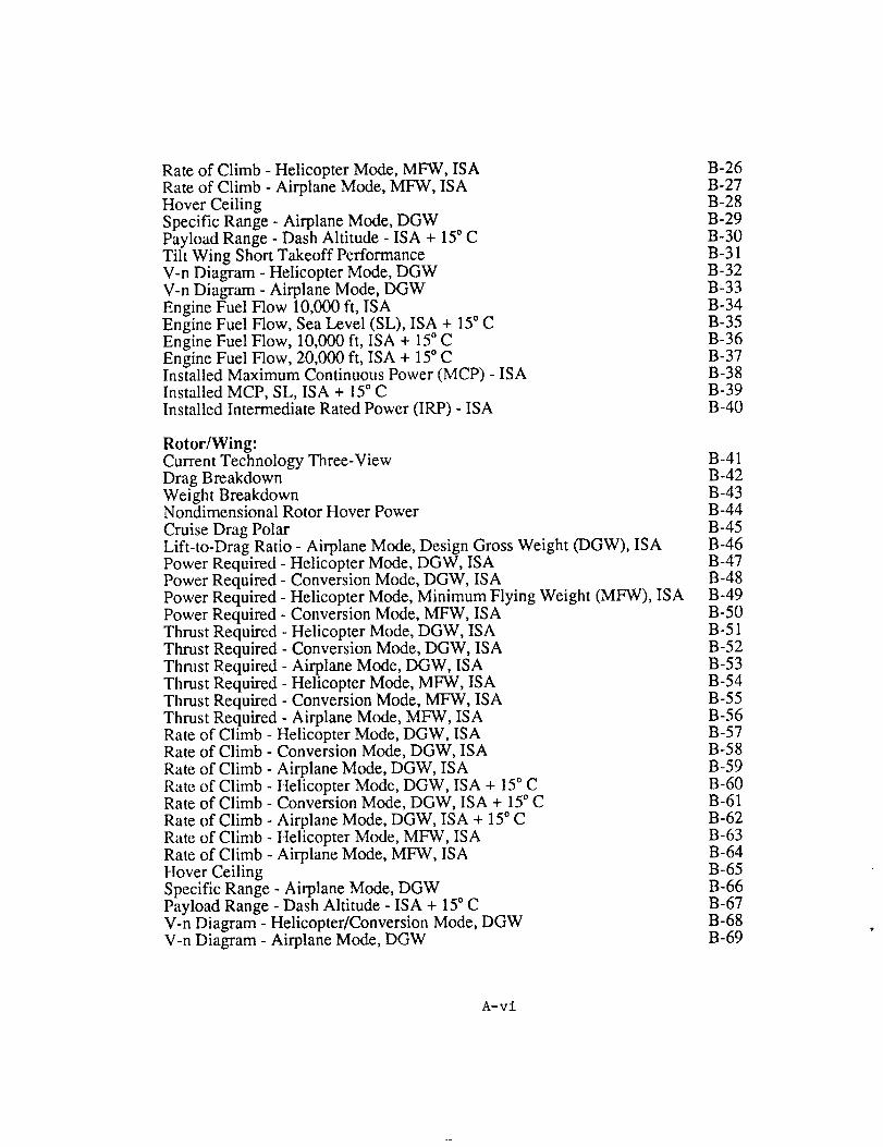
Rate of Climb - Helicopter Mode, MFW, ISARate of Climb - Airplane Mode, MFW, ISAHover CeilingSpecific Range - Airplane Mode, DGWPayload Range - Dash Altitude - ISA + 15° CTilt Wing Short Takeoff PerformanceV-n Diagram - Helicopter Mode, DGWV-n Diagram - Airplane Mode, DGWEngine Fuel Flow 10,000 ft, ISAEngine Fuel Flow, Sea Level (SL), ISA + 15" CEngine Fuel Flow, 10,000 ft, ISA + 15 ° CEngine Fuel Flow, 20,000 ft, ISA + 15 ° CInstalled Maximum Continuous Power (MCP) - ISAInstalled MCP, SL, ISA + 15" CInstalled Intermediate Rated Power (IRP) - ISA
B-26B-27B-28B-29B-30B-31B-32B-33B-34B-35B-36B-37B-38B-39B-40
Rotor/Wing:Current Technology Three-View B-41Drag Breakdown B-42Weight Breakdown B-43Nondimensional Rotor Hover Power B-44
Cruise Drag Polar B-45Lift-to-Drag Ratio - Airplane Mode, Design Gross Weight (DGW), ISA B-46Power Required - Helicopter Mode, DGW, ISA B-47Power Required - Conversion Mode, DGW, ISA B-48Power Required - Helicopter Mode, Minimum Flying Weight (MFW), ISA B-49Power Required - Conversion Mode, MFW, ISA B-50Thrust Required - Helicopter Mode, DGW, ISA B-51Thrust Required - Conversion Mode, DGW, ISA B-52Thrust Required - Airplane Mode, DGW, ISA B-53Thrust Required - Helicopter Mode, MFW, ISA B-54Thrust Required - Conversion Mode, MFW, ISA B-55Thrust Required - Airplane Mode, MFW, ISA B-56Rate of Climb - Helicopter Mode, DGW, ISA B-57Rate of Climb - Conversion Mode, DGW, ISA B-58Rate of Climb - Airplane Mode, DGW, ISA B-59Rate of Climb - Helicopter Mode, DGW, ISA + 15 ° C B-60Rate of Climb - Conversion Mode, DGW, ISA + 15° C B-61
Rate of Climb - Airplane Mode, DGW, ISA + 15° C B-62Rate of Climb - Helicopter Mode, MFW, ISA B-63Rate of Climb - Airplane Mode, MFW, ISA B-64Hover Ceiling B-65Specific Range - Airplane Mode, DGW B-66Payload Range - Dash Altitude - ISA + 15° C B-67V-n Diagram - Helicopter/Conversion Mode, DGW B-68V-n Diagram - Airplane Mode, DGW B-69
A-vi

Engine Fuel Flow SL, ISAEngine Fuel Flow 10,000 ft, ISAEngine Fuel Flow, 10,000 ft, ISA + 15" CEngine Fuel Flow, 20,000 ft, ISA + 15° CInstalled Engine Fuel Flow - Helicopter Mode - ISAInstalled Engine Fuel Flow - Helicopter Mode - ISA +15 ° CInstalled Maximum Continuous Thrust, SL, ISA + 15 ° CInstalled Intermediate Rated Thrust - ISAInstalled Intermediate Rated Thrust - ISA + 15 ° C
B-70B-71B-72B-73B-74B-75B-76B-77B-78
A-vii


PERFORMANCE MODELLING
The performance models which generated the data in Appendix B are, for the most part, simplemodels which have been substantiated at various points using more rigorous analyses. Thefollowing section will discuss the two engine models and the performance analyses used for boththe Tilt Wing and the Rotor/Wing in each mode of flight.
Tilt Wing
Engine Model- The engine model used for the Tilt Wing analyses is the Allison T406.An engine deck was provided to McDonnell Douglas Helicopter Company (MDHC) by themanufacturer. This deck is a computer model of the T406 which can be run at a variety ofpower settings to obtain rotor shaft horsepower (SHP) and fuel flow (FF) for any flightconditions. In order to use this model in the preliminary design process, it was necessary tonondimensionalize the engine data produced by the engine deck using turbine inlettemperature and flight conditions so that the preliminary design sizing program, VASCOMPII, could scale the engine data to the required engine size. This effectively allows use of T406engine technology without the need for a separate engine deck for each engine size requiredduring the preliminary design process.
Helicopter Mode- The helicopter mode performance was calculated using classicalhelicopter analysis found in such texts as Aerodynamics of the Helicopter by Gessow andMeyers, and .Aerodynamics of V/STOL Fligh_ by McCormick. Specifically, the rotor power wascalculated using momentum theory for the ideal power and strip theory for the profile power.Empirical corrections were implemented to account for the effects of compressibility and stall.
These calculations were validated in hover and vertical climb using LSAF (Reference 20 in themain text), an industry standard rotor hover performance program, and in forward flight usingflight test data from the MDHC AH-64A Apache. The wing of the Tilt Wing is assumed at 90degrees (vertical) for all helicopter mode analyses.
Conversion Mode- The conversion mode performance was analyzed using the same basicrotor model used in the helicopter mode analysis. For conversion mode, however, it is importantto find the wing attitude which trims the Tilt Wing at all airspeeds. For this reason, a forcebalance was added which trimmed the aircraft in conversion mode, checking the wing for stall atall airspeeds. The wing stall model uses Weissinger's lifting surface approximation, coupledwith momentum theory for the rotor wake effects, to calculate the lift and drag acting on thewing. This model was validated using flight test data from the XC-142. The model predictedthe XC-142 wing angle and stall boundaries quite accurately for all critical airspeeds.
Airplane Mode- The Airplane mode performance presented was calculated using theperformance subroutines within VASCOMP II. These methods are also classical in nature, withsubstantial use of empirical relationships (for Oswald's efficiency factor, compressibility dragcalculation, etc). The propeller performance was input as efficiencies dependent on the flight
A-ix
PRECEDLr_G PAGE BLANK NOT FILMED

condition. The propeller performance analysis was validated using V-22 propeller performancedata. It should be noted that the specific range plots presented were run with a constant propellerefficiency.
Rotor/Wing
Engine Model- The engine model used for all of the Rotor/Wing analyses is the Pratt &Whitney STF842 turbofan engine with a bypass ratio of one. Although this engine deck was notavailable, extensive engine data at different thrust levels and flight conditions along with scalingcurves was available in tabular format. This data was encoded and was automated in the
preliminary design process using a series of table lookups.
Helicopter Mode- The helicopter mode performance, like the Tilt Wing, was analyzedusing momentum and strip theory validated with LSAF in hover and vertical climb. It should benoted that the ideal power was calculated assuming only the rotor annulus area is lifting. Also,0015 airfoils were used in the strip theory analysis and incremented by 10% to account for theelliptical sections. This procedure was recommended based on the 1960's whirlstand testsconducted at Hughes Helicopter. Likewise, the profile power of the rotating centerbody wascalculated using an empirical correction based on the 1960's whirlstand tests. It should be notedthat the forward flight plots fail to sufficiently account for the effects of blade stall. These sametrends are shown in the 1960's forward flight performance data. This is not considered critical,however, because autorotative flight is initiated at approximately 80 knots. The power requiredand vibration levels in forward helicopter mode flight have been checked using CAMRAD JA
(Reference 21 in the main text).
The reaction drive internal flow analysis is based on the method outlined by Henry in"One-Dimensional, Compressible, Viscous Flow Relations Applicable to Flow in a DuctedHelicopter Blade," NACA TN 3089, .1953. This method employs basic thermodynamicrelationships along with empirical corrections based the previous reaction drive rotors. Theoutcome of this analysis is approximately 50 percent rotor system efficiency. In other words,
only 50 percent of the horsepower of the turbofan engine is converted into rotor power.
Conversion Mode- The autoratation data was calculated using basic momentum and strip
theory, and was validated using L/D values obtained during the 1960's wind tunnel tests. Asstated previously, the vibration levels near conversion speed have been checked using CAMRAD
JA. No analysis of rotor stopping has been conducted to date, however, dynamically scaled windtunnel tests conducted during the ,1960 s have demonstrated the feasibility of stopping the rotorwithout the use of any digital controllers.
Airplane Mode- The airplane mode of the Rotor/Wing., like the Tilt Wing, uses classicalfixed-wing analysis with empirical corrections where appropriate. The drag values in airplanemode compare favorably with those obtained during wind tunnel tests in the 1960's at HughesHelicopter.
A--X

APPENDIX A - TASK I SUBSTANTIATION
._ iii_>_i!!i!'!iI11 ._..,!_'!,;li
I",,,
i/'i
i I - "_!i;1!i;11 _ I -_. mr_
!|' 1==::_;i!_i"'_'!!l,- >_-_.,,,!_I [
u'l
i...a,.l=
A-!

A-2
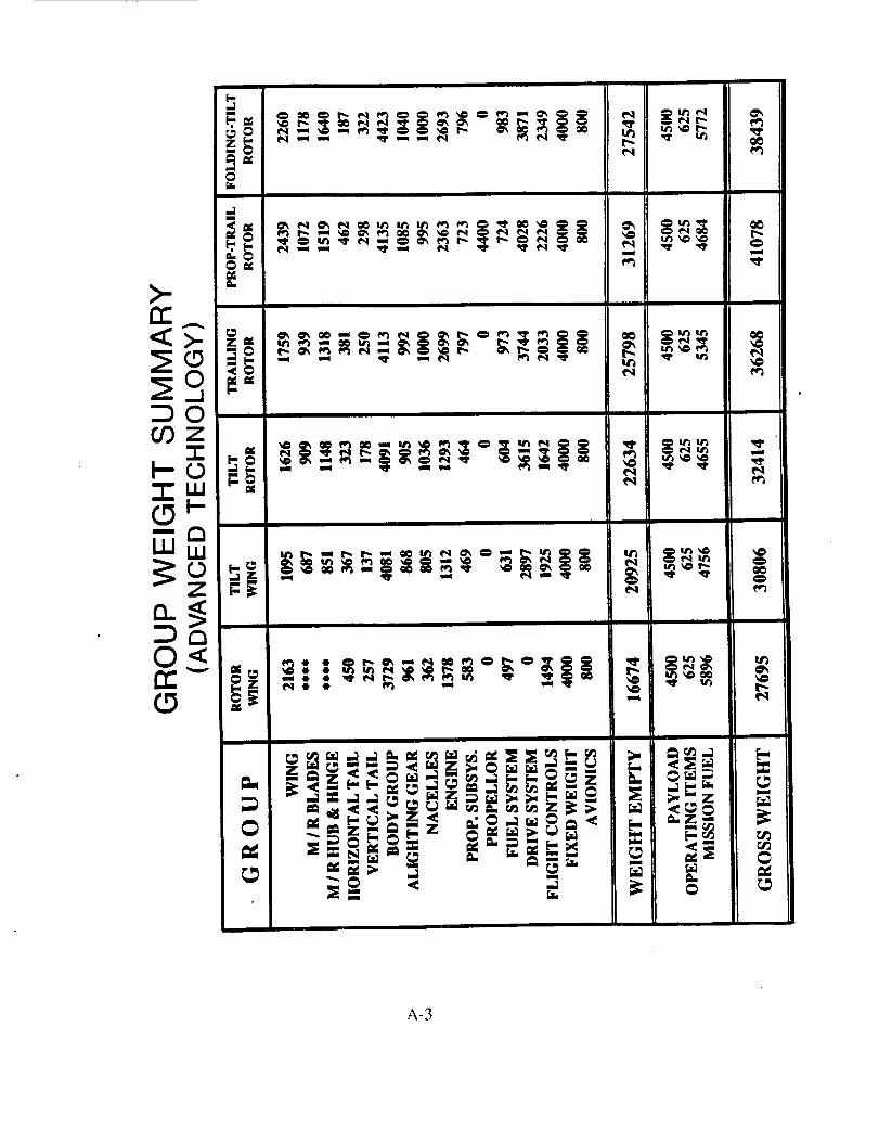
@
>.cc
:DO
eq
m
e4
e_
e_
A-3


APPENDIX B - TASK lI SUBSTANTIATION
%
j_ I_ r_
< - -d/
"_-'-_" _
I
_ kk
k
?
B-I
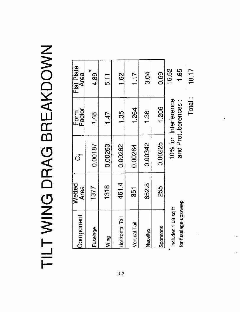
Z
0C_
(3.._ ._ CM I.r).-_-_ 0") ',- 04 I",.. _ 0") kO ¢4:)
n_ (:q..,-- _ .,-.:. o. _.,_-,=,,a" _i L6 .,-- ,-- co o.,-LL
'T'"
,:d
B
B-2

B-3

0
m
cE}c=0
a_
r_C:(DEc=0
Z
k=
A
, i i _ , I'" ' I i°l IIIIIIT'I' • '1' • i ,
0 0 0 0
_.01,. do '),uo!0Ujo03 sCrOd
i
to00
00
I--
d .,..;c-
O
0
00
' 60
o
B-4

0Q=
®
6=
(I)
m
<_0
.... I .... I .... I .... I .... i .... "i'
_ 0 0 0
70 _ue!0!;;eo3_;!7
C40
0
c5
0el.0
ID4m4.-q)0
.°0oa
0c_
o0
0
B-5

CO
iI
c--
0uI
=i
0I
0 i.==i
O4
0 _
o!l_)U8eJO=o1=)+J!l
00
0.tt_
0-0,_.
0u0
00..-_
v
o_
o<-o_
0up
00
0UD
0I .... I
B-6
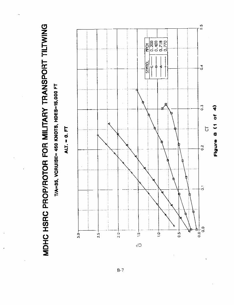
Zm
l--,'r"C)O.
=E _ ,.c_ _ _,
r¢" ®5
0
Q.
"r"
-I-0:E
0
®t,,
8-?
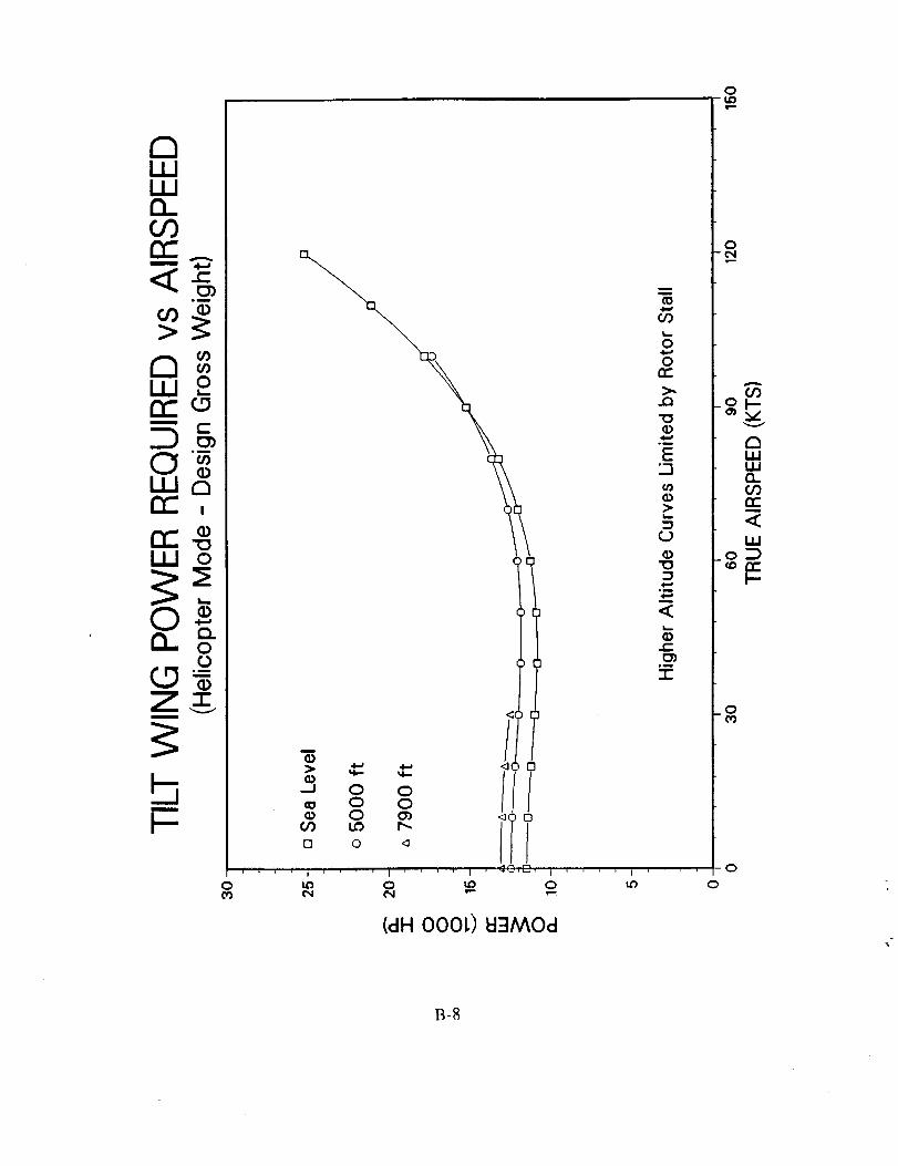
C3ILlILlncor_
Borr_
r_r_" ,
m
F-
00_
0
!
u
Q
(D._1 0 0
0 00 o'_
[] 0 _s l°0 _ 0
(dH O00L) I::l:l/WOd
I
('0
00
O
OE::
>,,
°_
E,_J
¢,/)
>.L--
:3rj
'13:3
..E
,m
"1-
O
O
ILlLLIr_
E:,<1.1.,I
_O:3
.O
O
o
B-8

LU
C_LU
I=kJ
00=
C_
0==
A
c-
(D
or)CO0
r_C::
im
cO(1)
Da
(1)
0
_,oooo / ,oooo o ,_
o
i
0
(dH O00t) pgJ!nbeld seMOd
0co
0uo
0
A
00
_o_.
<C
0¢o
0c_
0
lid
B-9

o0
vv
®o. :EcO
<_ -o.
c6 ._Q_
>rn
@(1> c
f.t)
0
(1) ,CO a'_L__ .C:
oI
Qe_:m=
IO-(D
rr _
0 0 0 0 00 0 0 0 00 0 0 0 00 _ 0 _ 0
(dH) Je_AodeSJOH peJ!nbel:l
I
000
00co
0tO
00,<.
0.uD
00,*--._r,.O
v
o._e_ Q
O.
o<I:
0-IJO
00
0
o
0
B-IO

e,..MJ
Qm
¢-U:J "_'.
m
u_
© a
O
.__o(1)
_=m
,,-I
i-i
<_
I<3
I<3
o o /0 0O O0 O_ _ 0 []
_ _.:,_,'-I. , II ' * ' I _
o i_ o
(dH) kFIMOd
O
O
.,Q
im
E0_
.-I
cD
L_
"O
0_
<
"T
O
O
a14.1IIIO,.gOrrm
<i11
o_
I--.-
O
O
o
B-11

0
A
r-
ken ._
C5 ._-LL]I >"¢w "
E
0 ,
(D
\o o0 00 00 0
¢xl
0 ,a
<1
! i i
(dH O00L) poJ!nbol:l JOMOd
0
,r.-,
0e,l
0O
_ooo
0")a..._
<
0
0
0
0
B-12
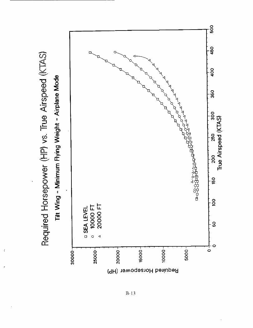
vV
(I)
co
<
0 .-_r_ :E(D 0CO
_r
r_
\
"t' t ! I I i
0 0 0 0 0 00 0 0 0 0 00 0 0 0 0 00 _ 0 uD 0
(dH) JgModgsJOH pgJ!nbglJ
0
0
0
B-13

E_LI_ILLi
O0re"
<CO>
C_LL!rr"m
C_1J_1or"
.T
(DZ
m
H-
wm
(D
cO
or_c-
co(D
n!
(D
O.0CO
(D"1-
w
--J 0 00 0
(,0 I.o I_,n 0 '_
0
J* ' ' ' I .... t I ' [] ' ' I
to 0 LO 0 LO
($87 0000 O3UINO3U 1S17_H1
oO
O0
a_
.0
E._
-,I
L_
,..
r-
7-
0
0
A
V
121U.lu.ln_
W
,0
0
0
B-14
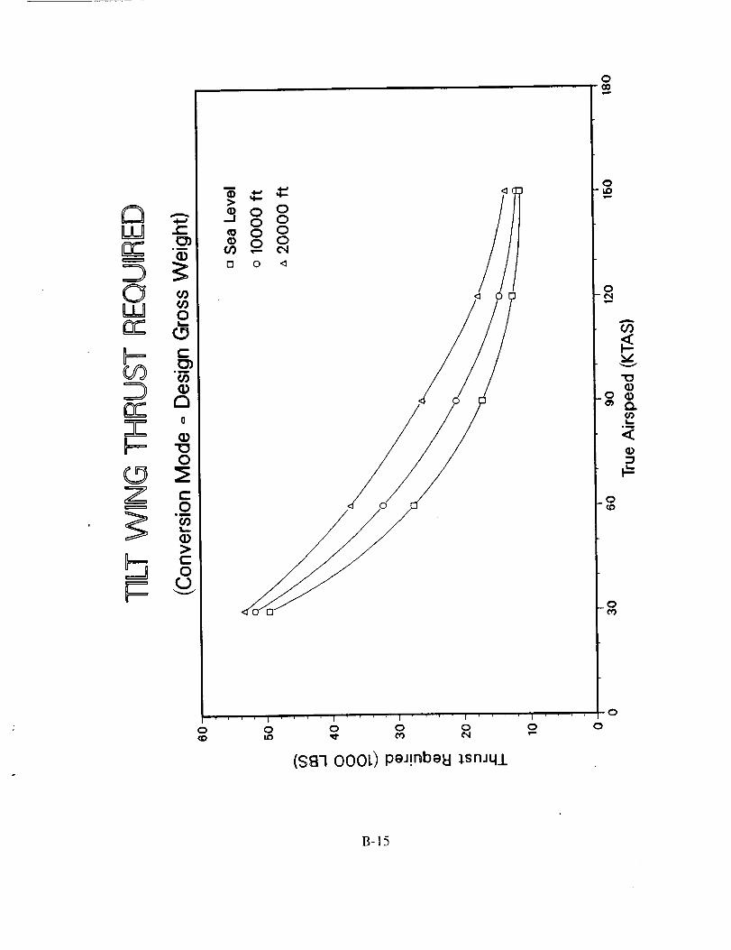
C_UJ 0rr"
O0
Z) ®a
EE °
o
1
o(o
!
oI I .... t
o o o
(S_I-IO00L) peJ!nbeEI isnJq..L
I
o
o
oup
o
CO
vv
LI
o
o
0
0
B-15

g-o _-mQ. 0
um,i
,m
B==1
O
C_ c_
iz
\
0
\ |
\ I
%°|<]
oo
.... I .... t .... I .... I .... I .... I .... I ....
o o o o o o o o0 0 0 0 0 0 0 00 0 0 0 0 0 0 0
(BI)6sJ(]
00
0LO
0-0
0
00..-_
O.
im
-o_
0u_
0-0
_0LO
0
0
B-16

LLq "_
"0
Z
oo
0
0
m
-_ 0 00 00 _'_
0 0 ,_
($8-1 000[) 1snJql peJ!nbeN
o
Ip,
0
U3
80
rr"
>..0
°_
E"'1
G)P
°_
t-O)
°_
"T"
0Lo
o
A
O0
vv
13.
L_°m
o =m
0
o
B-17

0
W
m_
w
++ +
I
Z
0
+gg
o o 1
0
+ + , , i I ! .... !
0 0 0¢_ ¢,,I ,--
($g] O00L) PeJmbeU _snJ_
0
0
A
O0
(/)L-
*i
0
0to
0
0
B-18

CO
v
©(DC_
u_
<(I>
>
0-o
ED
b..
C_
<,
g
E,m
ii
_EI
u
_z
o_
9
O"
'i .... i .... I .... i .... L
0 0 0 0 0 00 0 0 0 0 00 0 0 0 0 0
(BI) 6eJG
,i,1,,
00o
gtO
g
gco
g
.g
O-
L--Ju
o<
0,u0
00
0Lo
0
0
B-19

LWL_J
O0 O1mm
Z
t-
O
W rnU
X
Z. °-r
b
" O O
O 0
OOOco
I
OOOc0
O
O
(_dd) quJ!19 _o gJ,gkl
B-20

000
,m,,-
c2
!!!............Io0 0 0 0 0 00 0 0 0 00 O 0 0 00 _0 ,,o _ e,4
(dH) peJ!nbe8 Je_Od
B-21

0
up
O9
IZ)
EL
>
Eimmmn
L)14--0
(I}rr _
C
Q)
0
0u
u.m
000
- ;-:-i_' ' ' "-i-" ; ' _ .... t ' t ;O 0 0 0 00 0 0 0 00 0 0 0 0
(IAIdd) qm!IO I0 e:l._U
I''''
0 000
0u0
00,_.
0u_
(D
I.,,.0m
0-0
_0u_
0
B-22

i!0
LO
E_
o
a
L--
0.
8Q)
"1-
000
• []
(_dd) qw!lD j.0 e_.el::l
0
o
o_
-g
0cO
0
0
B-23

0
C_
0
LLJ
rr
X
o
+
m
-CZ
000
<]
<]
<]
0 oo 00 00 0
0 ,_
8 o
(_dd) qw!lO _o e_eU
000
0
B-24

#v
@O.
gm
@
' Em
4,--
0
@
o
+
m
(D
el.L_
.D
0
,i
c
,m
o0
D
F--
I0I
0t
0I
9
[]!
[3
0
[3I
\
0 0
I .... I I .... I I
0 0 0 0 0 00 0 0 0 0 00 0 0 0 0 0
(I/_ld-.I)qw!13:1.0 e_.eld
00i,,o
0I,o,,,¢
0-0
0uO
8.-.
i °0
O.
o'_o_
0ut_
0-0
0
0
0
B-25

Z=J0
0
W
X
Z
b
(D
O.00
IDm
07-
0
_9o__oo000 0
of _
g:7
o // o
//
T f, . , ,4 . I /'1. ,.,,,,,1 , 1 .' O, , , t '' ' " . ,_11 0
0 0 0 0 0 00 0 0 0 00 0 0 0 00 (_ _ _ C,I
(_dd) qw!13 :I.o e:l.gtd
B-26
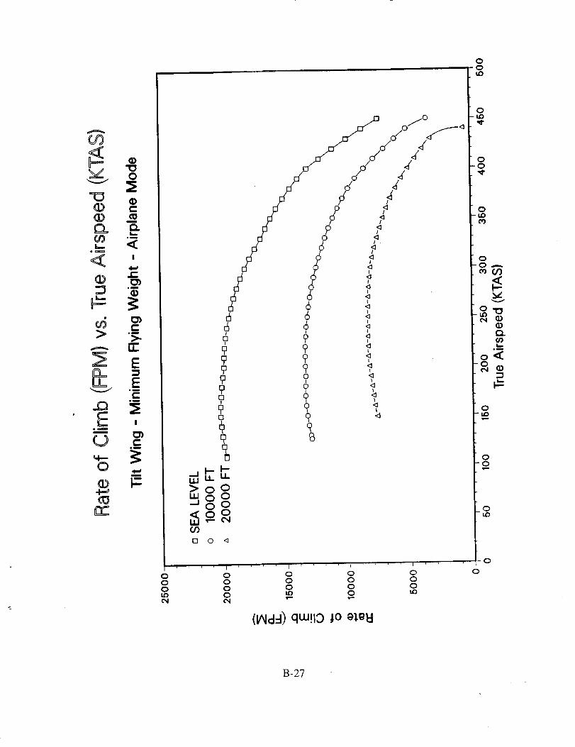
O0
m(D ,--
mu
L_
_'_ ,_
o6 m
rr"
u= fi
Ee_
(_ .__
0 .,..,u
rrr:'
000ldO
0
6I
[]I
oI
9999[]I
O3
o o <]
I
0000
jo
J/J/- /
r 0 _
!
!
1o <]
I
0 '_I
' ' ' I I t
o o o0 0 00 0 0_) 0 _'_
(lAid:l) qw!13:1.0 gJ,el:l
00u0
0LO
00
0LIDeO
0' 0 ,..._.
v
"10ooQ..(/,)I,,.,.
o
0i.o
00,i,,.,,,-
oi..o
o
o
B-27
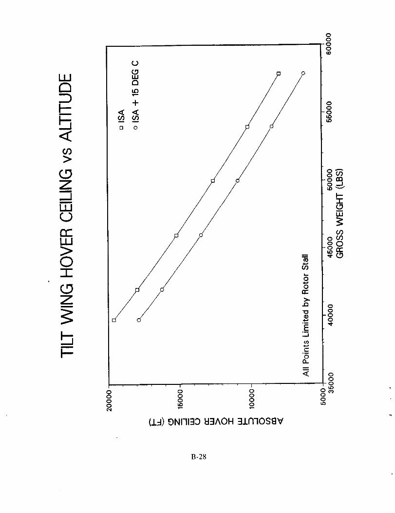
F-ro
O0>
Zm
..Jm
ILl0n,"ILl>0
Z
m
h-
0000c'N
! ' t
0 00 00 0u0 0
(1:1) 0N17130 _I3^OH :IIN70SSV
o
0000Qp
00
0ut_
(.9m
ILl
oOO
00
.00
000LO
OCO00LO
B-28

O_
L_om om
D(D ..
._Jc
C/)
, (1) 0
°_
u_
m_
0(D
O0
//
<_!
<_
jo/?
/? F
/ /
00u_
0-iJo
00
0
0_
o
0
L__m
o_-o ¢_
0-lad
0"0
.01,0
.... I .... I .... t1'''1 .... I .... I .... I .... I .... I ''T' '0
0 0 0 0 0 0 0 0 0d d o 0 d 6 d d d o o
(83/_N) eBu_ o!_!ood S
B-29

00
000
00o
00u_
Z
,,y-
(13-IO00L) 'PgOlAgd
B-30

LU
(0
(0LU
0
0
(c)
Cr_0
C9 Q"I0
(J
m
{3)
(1333) 4_6u_7 A_MunEI
B-31
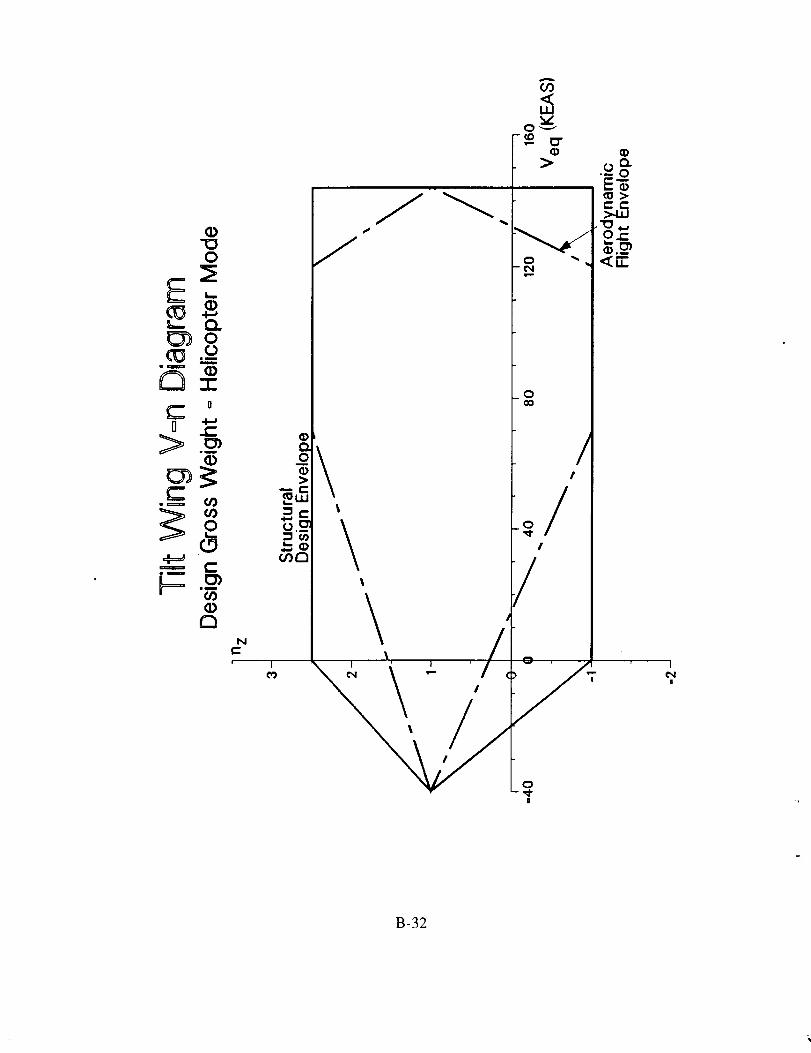
_om
0
_z<D
_== c-
a
A
F_ _F _ .-°_o
f "-_ I ®.__
NC
!_uJi
l
L 'i/,
0O0
/I
I
/
0
|
I
I
B-32
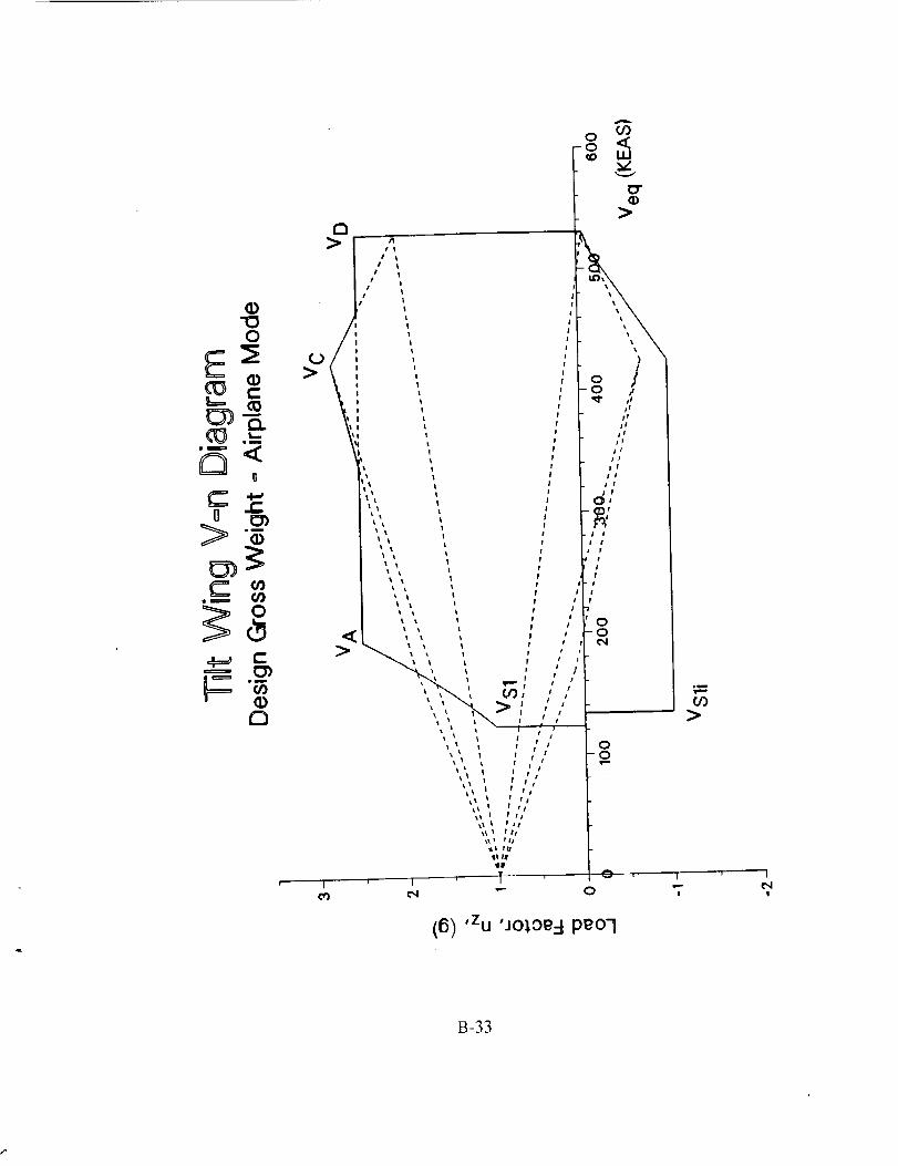
COo <
ID"(D
>D
O
,° /
] ,,
: //
° / j/
u_ \" ; / /
>
I
(Dn
_, " /I TM
',,',, / ,,
! to /
'',, ', I /,, o_ I I 0
,, ', :,, ,-I 1
I t tt
_I I f ll
$1 II
I$1P
, 1 l 1
e,I "-" 0
(6) 'Zu 'JO:l.Oe-Upeol
,u
(/)>
I I
!
B-33

3000
Installed Engine Fuel Flow
Tilt Wing - 10,000 FT, Standard Day
2500
2000
A
oc"I-
03..Jv
15000
U.
1000
500
0
10 100 200 300 400 450
True Airspeed (KTS)
6
B-34
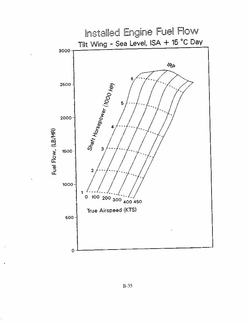
3000
OnstaDledEngine Fuel FlowTilt Wing = Sea Level, ISA + 15 °C Day
A
n'-"r
130--I
0IJ_
2500
200O-
1500
1000
500
0
0
4
2
0 100 200 300400 450
True Airspeed (KTS)
B-35

3000
lnstaDied Engine Fuel Fbw
Tilt Wing _-10,000 FT, DSA + 15 °C Day
2500
2000
cc
"_ 1500
lOOO
500
0
10 100 200 300 400 450
True Airspeed (KTS)
6
B-36

-r"
...iv
oJ
i1
2O00
1500
1000
500
0
_nstalled Engine FueB Flow
Tilt Wing = 20,000 FT, _SA + 15 °C Day
4
1
0 100 200 300 400 450
3oo
o
True Airspeed (KTS)
B-37

7000
6600
6000
5500a."1"
50000
0"1" 4500_D
(U
OD
4000
3600
3000
2500
OnstaOOedMCP Power AvailableTilt Wing =.Standard Day
0
100
True Airspeed (KTS)
200 300 400 450 EngineShaft
TorqueLimit
2O
B-38

lnstaOledMCP Power Available
7000
6500
6000 -
<_ 5500et"r
50000c_¢I)
0"I- 4500 -
(D
4000
3500
3000 -
2500
Tilt Wing = ISA + 15 °C Day
0
True Airspeed (KTS)
400 450 EngineShaft
300 Torque
Limit
200
100
5
2O
B-39

7000
lnstalged gRPPower AvailableTilt Wing = Standard Day
6500
6000
13-3::
Q)5ooo
0Ct.(D¢ot,.
0•"r- 4500
¢10,,m=
>< 4000
3600
3000
2500
True Airspeed (KTS)
0 0 100 200 300 400 450EngineShaft
TorqueLimit
5
20
B-40

J 1
_o
I
r_
0
_ J
B_41
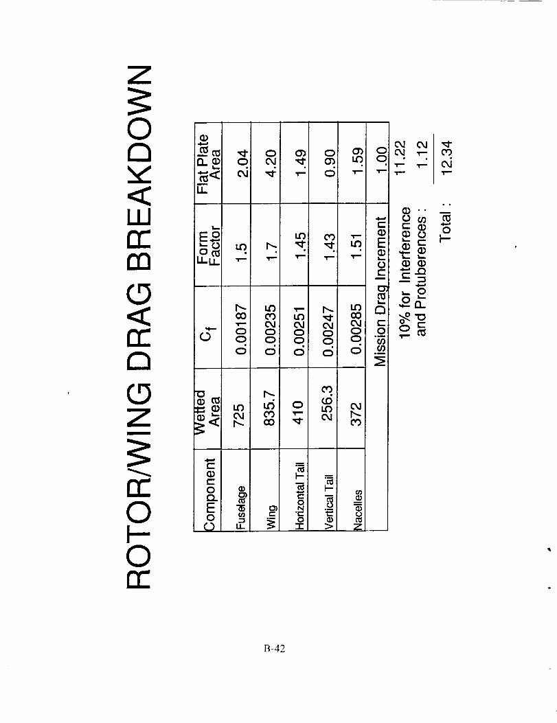
0O40d "_"
D__ o c_ ,_ 0_ Lo o •. _ _
rr o___o_o_°__0 0 0 0 0 "_ " _
d o d d o .__[_.!
I
m
rrO_
0 o_0
m°i
I-"
0N .--"_. I:= 00
B-42

Z
rn
W o,,• I--
,,-.
B-43

0
n
e=©
C®E
0Z
Z
©S
A
Q)k,,.
<
D
0
(10
L ,
o
c.OL*
I I ' I ' ' ' [] '
o 0 0
do "),um0uje0Z)Je_0d
00400
u_
0d
I--L.)
(,-(D
o,-
d (D0
(...)
0,0d
00o
o o
o
B-44
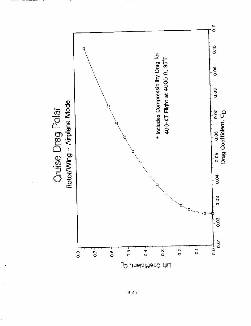
0 0 0 0 0 0 0 0
33 '),ue!o!:_teo3 _!q
oc5
000
0
0
0
o
o
o
0
0
c_0
0
B-45

a
C
C)gm
_=.=
a0
©
o
©,¢==_©
>
e o o0 00 00 0
N' ' ' 1 ' ' ' t I ' ' ' 1
0 O0 © "_
i
o4
00
0u_
00
0u_
v
o_
o_
0u_
00
0
0
0
B-46

00
O0_
r_
(D
©
Z
©r_0
ii1
(dH) JgMOd
0uo
co
B-47

o
CT
rr_
(D
o
Zc_
rr_
rr"
(o"0e-(o
cOu
¢)>
...J
(o(Dcoa
r-
,u
O9it)
0i...(._
e-
,m
o_(Dr_g
0(t)t_
>
0
0 0 0 0 00 0 0 0 00 0 0 0 0
(dH) .IgM0d
0
00
0
B-48
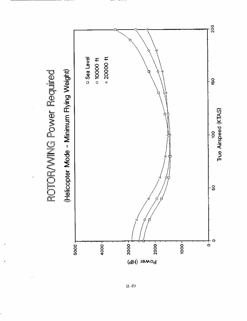
rr _ .__m
L. IJ_
o .E®?Z
rr _
S °
000LO
,O. 0--I_
_,oooc_D 0 <I
/J
i .... I d, _-E] , I
0 0 00 0 00 0 0
(dkl) .IgMOd
!
000
00o_
0
A
CO
LO
0
0
B-49

o._G "z
0
rr _0
0
000cN
"-i
o8
J121
/o
I I I
0 0 00 0 0Lo 0 ,m
(dH) JeM0d
0
i__wl
lid
0
0
B-50

0
¢r(D
n_
oO
<5Z
, ©cSn_
Ju
0L_.
c-
¢)C_
0
I,,.
Q.0(2
I_ I •
(I)
0000
0
o
(S_-I OOL) 3,snJqj.
0
B-51
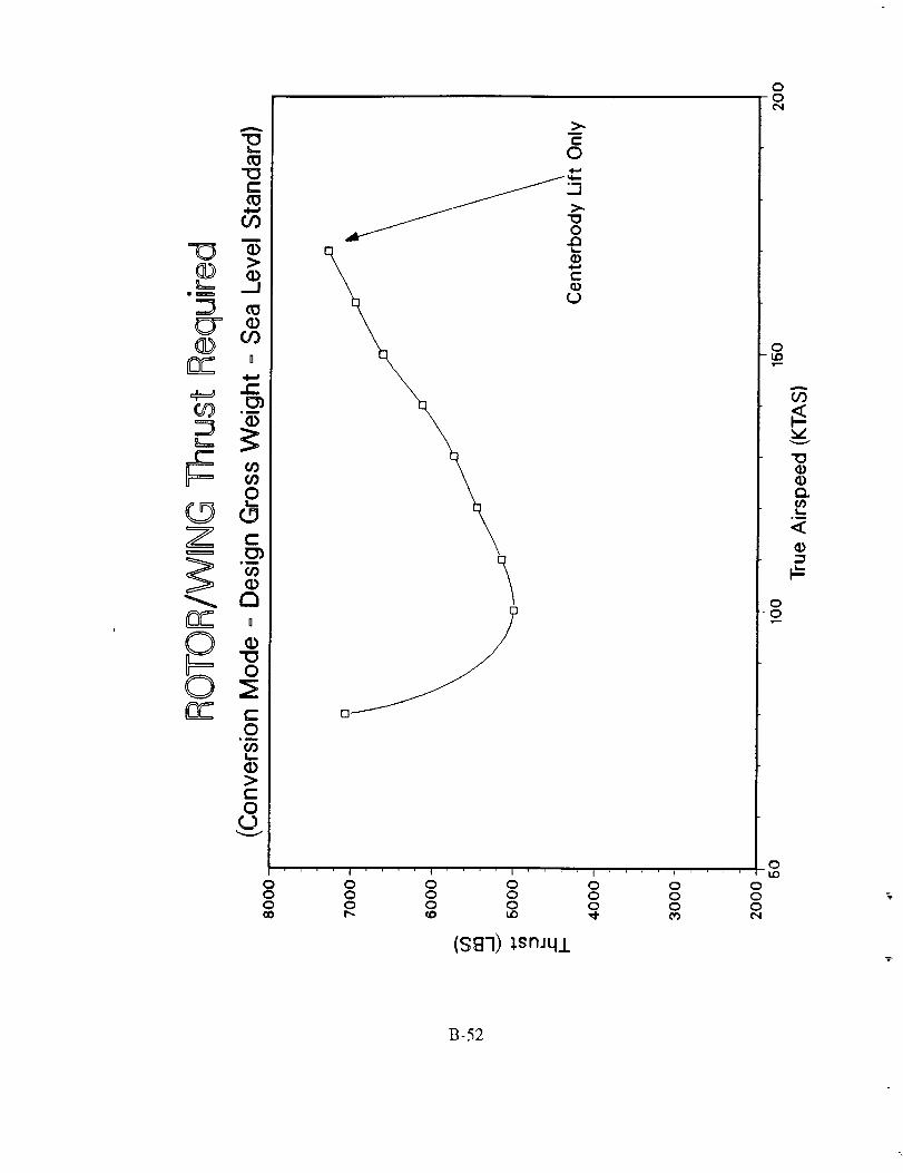
&..,,
(13
C:(13
CO
(13
cry,®
Z
C3
0o_
f_k_
(b>c-O
t-
O
fJ-_J >.
o
Q),,W
Q)
(.9
/J
D--"-"
i I I I I
0 0 0 0 0 0 00 0 0 0 0 0 00 0 0 0 0 0 0
(SBq) lsn.Jq/
00o,,I
0
,r,-.
Q.
I,.,..i
00
0
B-52

(I) (b
E
c-
a_:::=
n-c) o
#OocO eqO O <1
.... I .... I .... I .... I .... I .... I .... I .... I .... I ....
0 0 0 0 Q 0 0 0 0 0 00 0 0 0 0 0 0 0 0 00 0 0 0 0 0 0 0 0 C)
(B'i) ,b@lj. 'pe.J!nbeEI lsn.lqj.
00u:)
0
00
0
tO
V
-6
0&o
00
0
O
B-53

O
Z
©
A
lw
>.
E
E=_mi.
°°D
q_
Q)
0(2
-rv
0 0
0
(SB700I.) _snJ41
" I
00
cO
"o
-__<
Ou_
0
B-54

"O
m
_D
3_DCD
® 0c-
r-_== .-.
m
u_
0
t-o
c-o
0 0 0 0 0 00 0 0 0 0 00 _ 0 u_ 0 LO
(S£"1) l.snJq.L
0
000
B-55

0nO
o(D --om
L_
"0
n-
\
_h-h-_ U.. U-
_0 o
_o
0 0 0 0 0 0o o o o o g g g g g0 0 0 0 0 0 0 0 o 00 o_ 00 r_ t,o up _ o'J ¢_ "-
(87) 'bOil "PeJ!nbel=l lsm41
00u0
0
00
0
o_
0-to
00
0b0
0
B-56
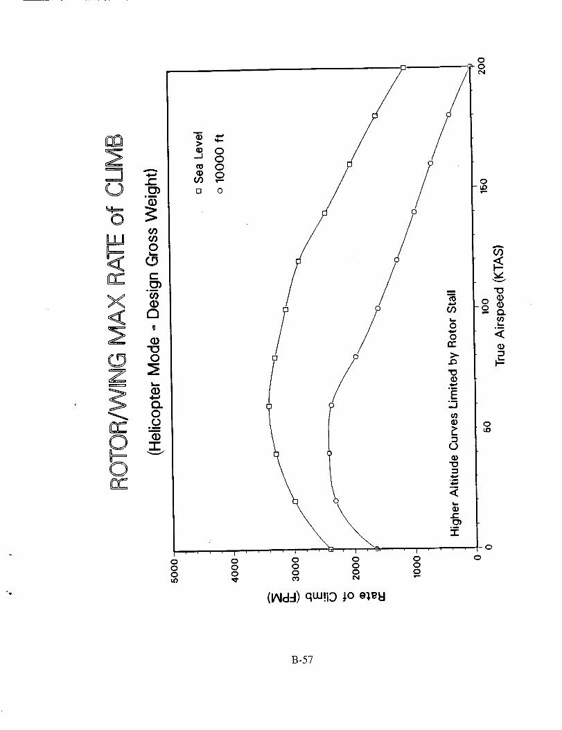
=J
C)
LU
X<Z
Z
©S
D
(1)"O
(D
13..OO
(D-r"
OOO
5_,o_o •00FI O
/ /
, , i , O, , ,
O OO OO O
OOO
oon-
il:..3¢0
L
(J
q
L_
.-r
I
O oOO
o
o
00L_
_)
Oup
o
(l_ldd) qw!19 _o e_l
B-57

(J
©
LLJ
X
Z
Z
©
S
(_dd) q_!13 j.0 eleH
oo
o
A
L__u
<
B-58
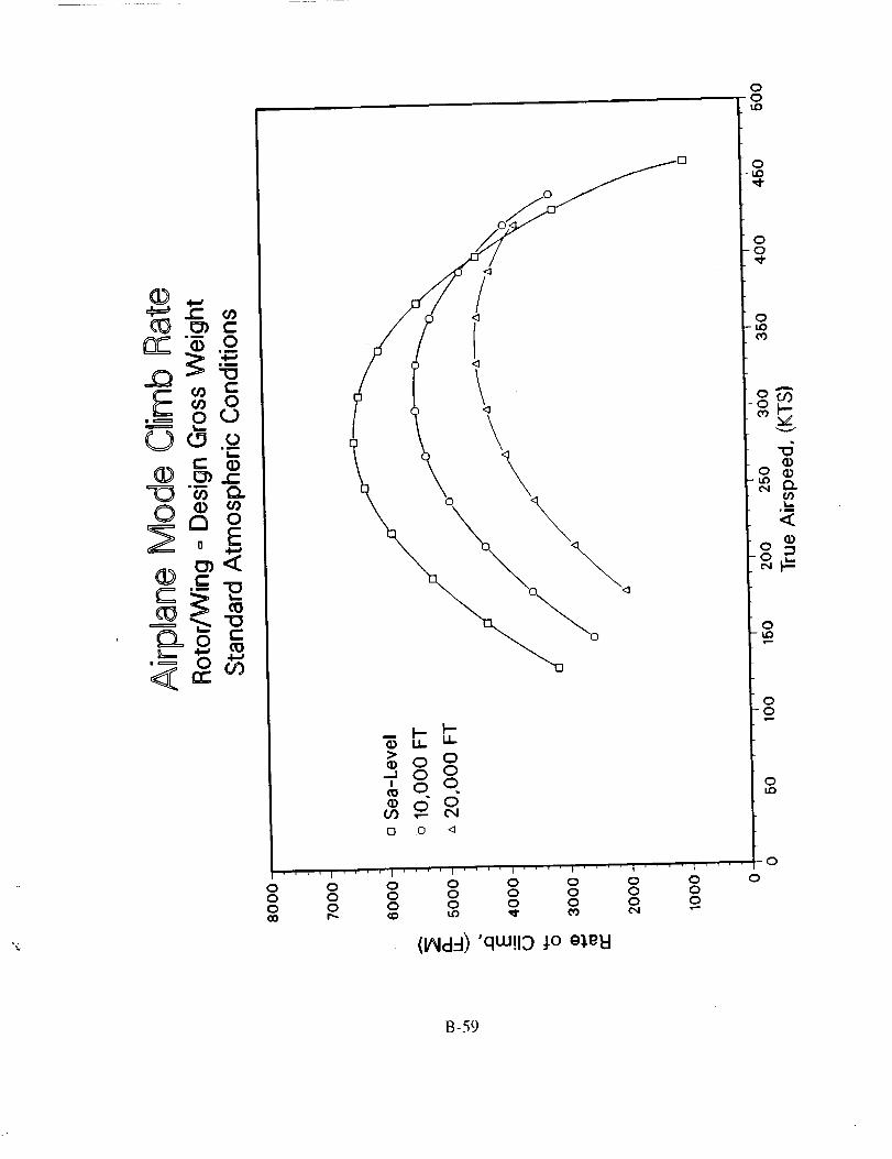
.l-w
JO
, 0 Q.),====_ L_
®_=(Z_" 0-
0
o_rr-
_o_
<_
\\
\ \
_oo_, o o
0 0 0 0 0 0 0 00 0 0 0 0 0 0 00 0 0 0 0 0 0 0
(IAIdd) 'qw!19 _o e),eld
00I.o
o-I.0
0
-0
0-Iz)cO
0
vV
Q)oo
(f)L..
°mw
0
00
0
0
B-59

Z==J(0
0
LLJ
X<CZ
Z
rr_
rrr
A
o0
I.O
-F
COm
U
r-
co
0L_
0r-
or;0
a0
0
I..--
0
o0
.m
(1)
_oCO
tn o
oooLt)
I
ooo
i
000
(_dq) qw!lO _o e_.e_
00e,I
0
O9
vv
0
0LO
0
B-60

Z
©
W
X
Z
©S
A
o
1.0
+
m
u
11)
U
Or)C/)0kD
uu
¢0
13U
o
0
I t
0 O 00 0 00 0 0
(l_dd) qm!13 J.0 g_gkl
00
0
O
vv
(D
Q.
°_
(1)
00
Oi.o
B-61

(D
o +
D
-J, o o
O3
!2 0 "_
0 0 0 0 0 0 0 00 0 0 0 0 0 0 00 0 0 0 0 0 0 0
(lAid--I) 'qw!13 J.0 g_.g_
0
0-ko
00,,¢
0
eO
V
tq
0lid
00
0
0
B-62

Z=J
0
LLJ
X
Z
_E©B
E
0 0 <_
0 0 0 0 0 00 0 0 0 0 00 0 0 0 0 0
(IAid:l)dw!Io :1.0 g_.g'd
00
0
0
0
B-63

.=
0 <
<o
I0
q
<]
>_0 o
_ d
n o <1
.... t .... I .... i''''I '''
0 0 0 0 00 0 0 0 00 0 0 0 0_,) ('4 '- 0
'I .... I .... I .... I .... I .... I .... I .... I ....
0 0 0 0 0 0 0 0 00 0 0 0 0 0 0 00 0 0 0 0 0 0 0
r,,, ci_ LO ,_- 0'} 04 ,,-
(IAIdd) "qw!lO j.o eJ,_l
00Lo
0LD
00,_.
0uoo'j
-6Q)
0uo
00
0Lo
o
,q
f
B-64

LD
,=JkkJ
kkJ
0EE
C_
0000_9
000i.o
0 0 00 0 00 0 00 u0 0
(.L-I) 8U!l!g3 JeAOH gqv
000i.o
0
000
000
oUt_
B-65

_D(I)Q_tn_
_6 CU .0
czo (0
mu
el
oQO.cO
_t
6
I
eQ
6
_ U. II
_o o
_ q®do
o
600
[ , _ r, I ' ' _ [ ' ' ' '
0 0 o 0o 6 o o
(Q-I/INN) 'eOueEI 0!_.!0edS
00u0
0
0o
0
09
o0
o
B-66

0
0.00
00
0
(D 0
('a-I O00L) 'pg01Agd
00
00
00
B-67
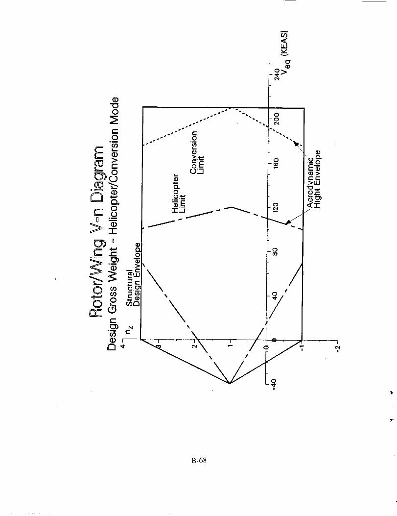
(/)
-_>
/
o
I
I
B-68

<
0
(13<I.Uvv
0 4)
I
I1 | II I
i I I
,, ', ; o ,• I I
I
|
,, , , o .¢ I
', ', I "* /,tl ii
t_ I I I I1_ _ _ jr
" ', o ,/,, , , _o,,
t I I I
; I
, ', , .0'I
I r I I
,, ,, : ;oo
'', ', l /'
"_l) Oe)l _ '"\', "_\. I _' '
I
I I I I l
I _ I I t
_t t I II
tl r#
I ' I 1 ' __l" ¢0 ¢_ _" 0
>
ii
O9>
I
|
B-69

50OO
OnstaHbd Engine FueO Fbw
Rotor/Wing -- Sea Level, Standard Day
4500
4000
3600
CC
,.n 3000
"3" 2500
2000
1600
1000.
500
0 10
B-70

4000
lnstaiUed Engine Fuel FUow
Rotor/Wing = 10,000 FT, Standard Day
x%
V
0iim
(o
ii
3500
3000
2500-
2000
1500
1000 -
5OO
0
3500
2500
1500
10
B-71

3500
3000
2500
A
EC"r"
._1
2000-0
1500
1000
5000
8nsta0RedEngine FueBF0ow
Rotor/Wing = 10,OOO FT, ISA + 115"C Day
10
B-72

"1-
t__J
V
oU-
u_
3000
2500
2000
1500
1000
500
InstaBUedEngine Fuel Flow
Rotor/Wing = 20,000 FT, ISA + 15 °C Day
0
6OO400
300
200 _y._s_100
10
B-73
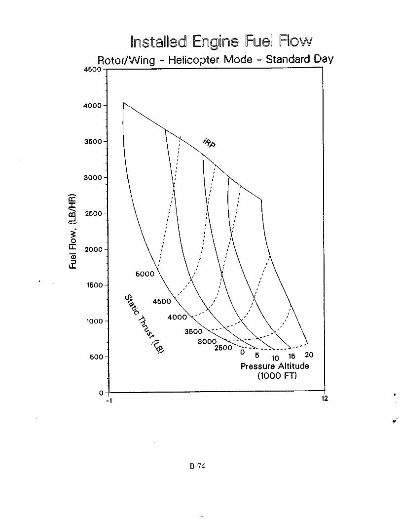
t_n._1
OnstaD6edEngine FueU FlowRotor/Wing - Helicopter Mode = Standard Day
4500
4OOO
3500
3000
2500
2OOO
1500
1000
500
0
I
5000
I
i I
I
0 5 10 15 20
Pressure Altitude
(lOOO FT)
12
B-74
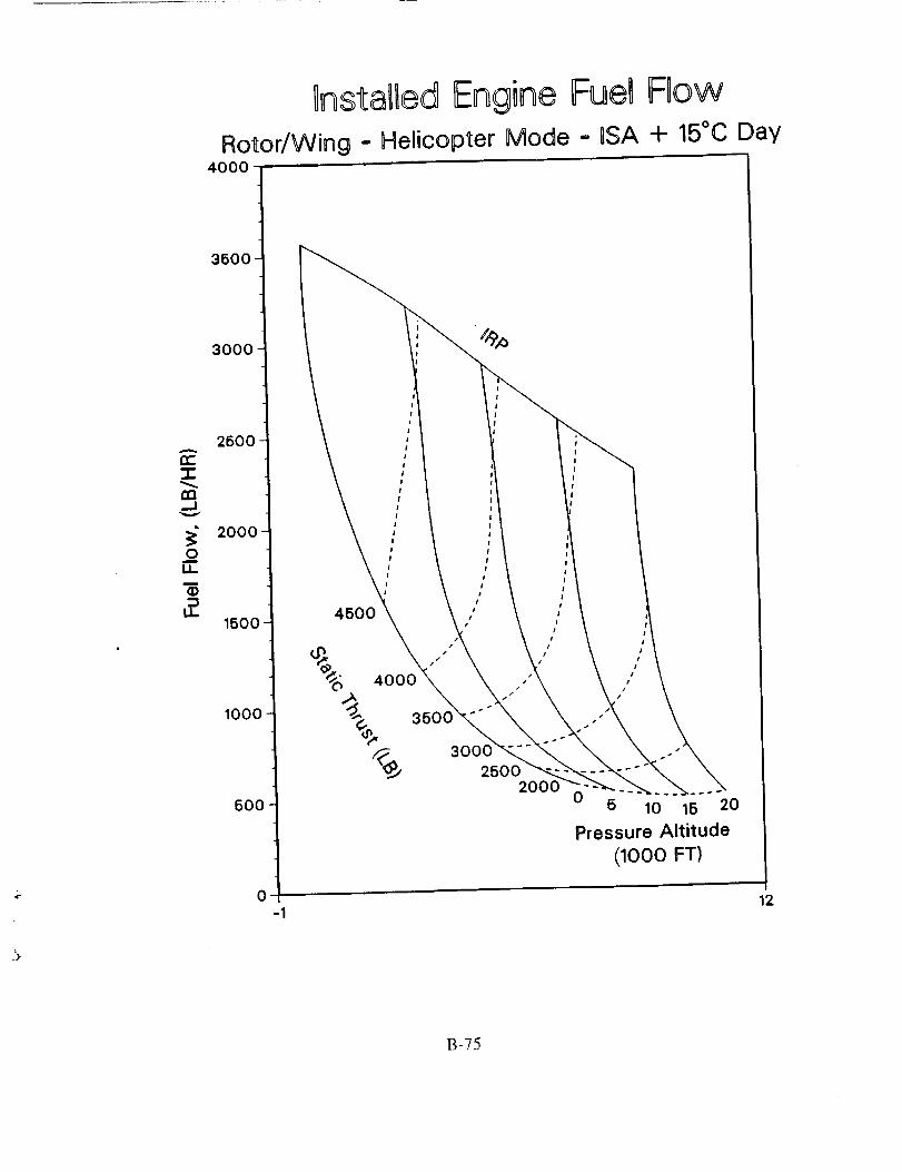
]nstaUled Engine Fuel FlowRotor/Wing = Helicopter Mode = USA + 15°C Day
4000
3500-
3000
2500
CC
U3_Uv
2000
1500
1000 -
500
0
0 5 10 15 20
Pressure Altitude
(1000 FT)
12
B-75
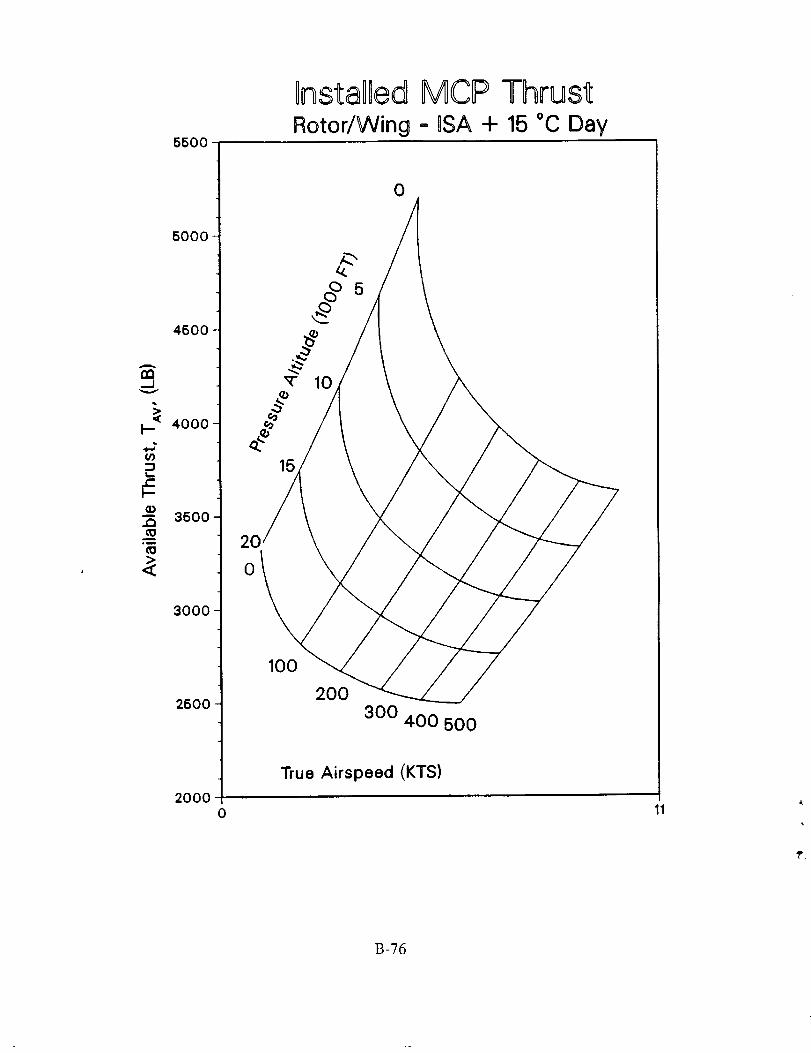
A
n__J
V
5500
5000
450O
G)._ 3500
3000-
2500
20000
20
Or_staOBedMCIP ThrustRotor/Wing = DSA + 15 °C Day
0
5
100
200
300 400 500
True Airspeed (KTS)
11
B-76
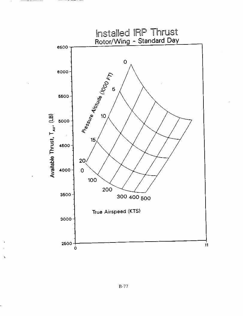
8500
InstaOledRotor/Wing
DRP Thrust= Standard Day
6000
5500
A
U3..J-._ 5000
k-
(/)
4500
a)
i 4000
3500
3000
2500
/15
2
o\100
0
0
I0
200
300 400 500
True Airspeed (KTS)
11
B-77

5500
5000
4500'
=,
4000
m
..0
,m
3500
3000
2500
DnstaIDedRotor/Wing
0
0
IRP Thrust-0SA+ 15°CDay
0
15
10
100200
300400 500
True Airspeed (KTS)
11
B-78

Nalor_l A_ks sr_
Space Adm_is_d_
1. Report No.
NASA CR-177578
Report Documentation Page
2. Government A_e'ssion No.' .....
4. Title and Subtitle
Technology Needs for High-Speed Rotorcraft
7. Author(s)
John Rutherford, Matthew O'Rourke, Christopher Martin,
Marc Lovenguth, and Clark Mitchell
3. Recipient's Catalog NO.
5. Report Date
April 1991
6. Performing Organization Code
8. Performing Organization Report No.
L9KVAE-FR-91001
10. Work Unit No.
532-06-37
11. Contract or Grant No.
NAS 2-13070
13. Type of Report and Period Covered
Contractor Report
! 4. Sponsoring Agency Code
9. Performing Organization Name and Address
McDonnell Douglas Helicopter Company
Mesa, Arizona
12. Sponsoring Agency Name and Address
Ames Research Center
Moffett Field, CA 94035-1000
15. Supplementary Notes
Point of Contact: P.D. Talbot, Ames Research Center, MS 237-5, Moffett Field, CA 94035-I000
(415) 604-5108 or FTS 464-5108
16. Abstract
A study to determine the technology development required for high-speed rotorcraft development was
conducted. The study begins with an initial assessment of six concepts capable of flight at, or greater than
450 knots with helicopter-like hover efficiency (disk loading less than 50 psf). These concepts were sized
and evaluated based on measures of effectiveness and operational considerations. Additionally, an initial
assessment of the impact of technology advances on the vehicles attributes was made. From these initial
concepts a tilt wing and rotor/wing concepts were selected for further evaluation. A more detailed
examination of conversion and technology trade studies were conducted on these two vehicles, each sized
for a different mission. Results of the trade studies indicate the importance of meeting IHPTET goals for
both concepts. The tilt wing also benefitted greatly from increased wing loading through improved high-
lift capability of its wing. The rotor/wing benefits from increased conversion wing loading leading to
reduced drag and more benign conversion characteristics. Finally, proposed technology development
times lines are presented for each technology area.
17. Key Words (Suggested by Author(s))
High-speed rotorcraft, Rotorcraft technology,
Tilt wing, Rotor/wing, Reaction drive rotors,Conversion
19. Security Classif. (of this report)
Unclassified
NASA FORM 1626 oc'rs_
18. Distribution Statement
Unclassified-Unlimited
Subject Category - 05
20. Security Classif. (of this page) 21. No. of Pages 22. Price
Unclassified 256 A 12
For sale by the National Technical Information Service, Springfield, Virginia 22161

Copyright © 2022 FDOKUMEN