Easy Access Rules for Large Rotorcraft (CS-29) (Amendment 5)
305
CS-29 (Amendment 5)
-
Upload
khangminh22 -
Category
Documents
-
view
2 -
download
0
Transcript of Easy Access Rules for Large Rotorcraft (CS-29) (Amendment 5)

CS-
29
(A
me
nd
me
nt
5)
Powered by EASA eRules Page 2 of 305| Jun 2019
Easy Access Rules for Large Rotorcraft (CS-29) (Amendment 5)
EASA eRules: aviation rules for the 21st century
Rules and regulations are the core of the European Union civil aviation system. The aim of the EASA
eRules project is to make them accessible in an efficient and reliable way to stakeholders.
EASA eRules will be a comprehensive, single system for the drafting, sharing and storing of rules. It
will be the single source for all aviation safety rules applicable to European airspace users. It will offer
easy (online) access to all rules and regulations as well as new and innovative applications such as
rulemaking process automation, stakeholder consultation, cross-referencing, and comparison with
ICAO and third countries’ standards.
To achieve these ambitious objectives, the EASA eRules project is structured in ten modules to cover
all aviation rules and innovative functionalities.
The EASA eRules system is developed and implemented in close cooperation with Member States and
aviation industry to ensure that all its capabilities are relevant and effective.
Published June 20191
1 The published date represents the date when the consolidated version of the document was generated.

Easy Access Rules for Large Rotorcraft (CS-29) (Amendment 5)
Disclaimer
Powered by EASA eRules Page 3 of 305| Jun 2019
DISCLAIMER
This version is issued by the European Union Aviation Safety Agency (EASA) in order to provide its stakeholders with an updated and easy-to-read publication. It has been prepared by putting together the certification specifications with the related acceptable means of compliance and guidance material. However, this is not an official publication and EASA accepts no liability for damage of any kind resulting from the risks inherent in the use of this document.

Easy Access Rules for Large Rotorcraft (CS-29) (Amendment 5)
Note from the editor
Powered by EASA eRules Page 4 of 305| Jun 2019
NOTE FROM THE EDITOR
The content of this document is arranged as follows: the certification specifications (CS) are followed by the related acceptable means of compliance (AMC) and guidance material (GM) paragraph(s).
All elements (i.e. CS, AMC and GM) are colour-coded and can be identified according to the illustration below. The EASA Executive Director (ED) decision through which the point or paragraph was introduced or last amended is indicated below the paragraph title(s) in italics.
Certification specification ED decision
Acceptable means of compliance ED decision
Guidance material ED decision
The format of this document has been adjusted to make it user-friendly and for reference purposes. Any comments should be sent to [email protected].

Easy Access Rules for Large Rotorcraft (CS-29) (Amendment 5)
Incorporated amendments
Powered by EASA eRules Page 5 of 305| Jun 2019
INCORPORATED AMENDMENTS
CS/AMC/GM (ED DECISIONS)
Incorporated ED Decision CS/AMC Issue No, Amendment No Applicability date
ED Decision 2003/16/RM CS-29/ Initial issue 14/11/2003
ED Decision 2007/014/R CS-29/ Amendment 1 30/11/2007
ED Decision 2008/010/R CS-29/ Amendment 2 17/11/2008
ED Decision 2012/022/R CS-29/ Amendment 3 18/12/2012
ED Decision 2016/025/R CS-29/ Amendment 4 2/12/2016
ED Decision 2018/007/R CS-29/ Amendment 5 26/6/2018
Note: To access the official versions, please click on the hyperlinks provided above.
Easy Access Rules for Large Rotorcraft (CS-29) (Amendment 5)
Table of contents
Powered by EASA eRules Page 6 of 305| Jun 2019
TABLE OF CONTENTS
Disclaimer ...................................................................................... 3
Note from the editor ...................................................................... 4
Incorporated amendments ............................................................. 5
Table of contents ........................................................................... 6
Preamble ..................................................................................... 17
Subpart A — General ................................................................... 20
AMC 29 General .................................................................................................................. 20
CS 29.1 Applicability ......................................................................................................... 20
Subpart B — Flight ....................................................................... 21
GENERAL ............................................................................................................... 21
CS 29.21 Proof of compliance........................................................................................... 21
CS 29.25 Weight limits ...................................................................................................... 21
CS 29.27 Centre of gravity limits ...................................................................................... 22
CS 29.29 Empty weight and corresponding centre of gravity .......................................... 22
CS 29.31 Removable ballast ............................................................................................. 22
CS 29.33 Main rotor speed and pitch limits ..................................................................... 23
PERFORMANCE ...................................................................................................... 24
CS 29.45 General .............................................................................................................. 24
CS 29.49 Performance at minimum operating speed ...................................................... 24
CS 29.51 Take-off data: General ....................................................................................... 25
CS 29.53 Take-off: Category A .......................................................................................... 25
CS 29.55 Take-off Decision Point: Category A .................................................................. 25
CS 29.59 Take-off Path: Category A .................................................................................. 26
CS 29.60 Elevated heliport take-off path: Category A ...................................................... 26
CS 29.61 Take-off distance: Category A ........................................................................... 27
CS 29.62 Rejected take-off: Category A ........................................................................... 27
CS 29.63 Take-off: Category B .......................................................................................... 27
CS 29.64 Climb: General ................................................................................................... 28
CS 29.65 Climb: All engines operating .............................................................................. 28
CS 29.67 Climb: One Engine Inoperative (OEI) ................................................................. 28
CS 29.71 Helicopter angle of glide: Category B ................................................................ 29
Easy Access Rules for Large Rotorcraft (CS-29) (Amendment 5)
Table of contents
Powered by EASA eRules Page 7 of 305| Jun 2019
CS 29.75 Landing: General ................................................................................................ 29
CS 29.77 Landing Decision Point: Category A ................................................................... 30
CS 29.79 Landing: Category A ........................................................................................... 30
CS 29.81 Landing distance (ground level sites): Category A............................................. 30
CS 29.83 Landing: Category B ........................................................................................... 30
CS 29.85 Balked landing: Category A ................................................................................ 31
CS 29.87 Height-velocity envelope ................................................................................... 31
FLIGHT CHARACTERISTICS ...................................................................................... 32
CS 29.141 General ............................................................................................................ 32
Appendix B – Airworthiness Criteria for Helicopter Instrument Flight .................. 32
CS 29.143 Controllability and manoeuvrability ................................................................ 36
CS 29.151 Flight controls .................................................................................................. 37
CS 29.161 Trim control ..................................................................................................... 37
CS 29.171 Stability: general .............................................................................................. 38
CS 29.173 Static longitudinal stability .............................................................................. 38
CS 29.175 Demonstration of static longitudinal stability ................................................. 38
CS 29.177 Static directional stability ................................................................................ 39
CS 29.181 Dynamic stability: Category A rotorcraft ......................................................... 40
GROUND AND WATER HANDLING CHARACTERISTICS ............................................. 41
CS 29.231 General ............................................................................................................ 41
CS 29.235 Taxying condition ............................................................................................. 41
CS 29.239 Spray characteristics ........................................................................................ 41
CS 29.241 Ground resonance ........................................................................................... 41
MISCELLANEOUS FLIGHT REQUIREMENTS .............................................................. 42
CS 29.251 Vibration .......................................................................................................... 42
Subpart C — Strength requirements ............................................. 43
GENERAL ............................................................................................................... 43
CS 29.301 Loads ................................................................................................................ 43
CS 29.303 Factor of safety ................................................................................................ 43
CS 29.305 Strength and deformation ............................................................................... 43
CS 29.307 Proof of structure ............................................................................................ 43
CS 29.309 Design limitations ............................................................................................ 44
FLIGHT LOADS........................................................................................................ 45
CS 29.321 General ............................................................................................................ 45
CS 29.337 Limit manoeuvring load factor ........................................................................ 45
CS 29.339 Resultant limit manoeuvring loads .................................................................. 45
CS 29.341 Gust loads ........................................................................................................ 46
Easy Access Rules for Large Rotorcraft (CS-29) (Amendment 5)
Table of contents
Powered by EASA eRules Page 8 of 305| Jun 2019
CS 29.351 Yawing conditions ............................................................................................ 46 AMC No 1 to CS 29.351 Yawing conditions ......................................................................... 46 AMC No 2 to CS 29.351 Yaw manoeuvre conditions .......................................................... 49
CS 29.361 Engine torque .................................................................................................. 50
CONTROL SURFACE AND SYSTEM LOADS ................................................................ 51
CS 29.391 General ............................................................................................................ 51
CS 29.395 Control system ................................................................................................. 51
CS 29.397 Limit pilot forces and torques ......................................................................... 51
CS 29.399 Dual control system ......................................................................................... 52
CS 29.411 Ground clearance: tail rotor guard .................................................................. 52
CS 29.427 Unsymmetrical loads ....................................................................................... 52
GROUND LOADS .................................................................................................... 53
CS 29.471 General ............................................................................................................ 53
CS 29.473 Ground loading conditions and assumptions .................................................. 53
CS 29.475 Tyres and shock absorbers .............................................................................. 53
CS 29.477 Landing gear arrangement .............................................................................. 53
CS 29.479 Level landing conditions .................................................................................. 53
CS 29.481 Tail-down landing conditions .......................................................................... 54
CS 29.483 One-wheel landing conditions ......................................................................... 54
CS 29.485 Lateral drift landing conditions ....................................................................... 54
CS 29.493 Braked roll conditions ...................................................................................... 55
CS 29.497 Ground loading conditions: landing gear with tail wheels .............................. 55
CS 29.501 Ground loading conditions: landing gear with skids ....................................... 57
CS 29.505 Ski landing conditions ...................................................................................... 58
CS 29.511 Ground load: unsymmetrical loads on multiple-wheel units .......................... 59
WATER LOADS ....................................................................................................... 60
CS 29.519 Hull type rotorcraft: Water-based and amphibian .......................................... 60
CS 29.521 Float landing conditions .................................................................................. 60
MAIN COMPONENT REQUIREMENTS ..................................................................... 62
CS 29.547 Main and tail rotor structure ........................................................................... 62 AMC 29.547 Main rotor and tail rotor structure ................................................................ 62
CS 29.549 Fuselage and rotor pylon structures ............................................................... 62
CS 29.551 Auxiliary lifting surfaces ................................................................................... 63
EMERGENCY LANDING CONDITIONS ...................................................................... 64
CS 29.561 General ............................................................................................................ 64
CS 29.562 Emergency landing dynamic conditions .......................................................... 65
CS 29.563 Structural ditching and emergency flotation provisions ................................. 66 AMC 29.563 Structural ditching and emergency flotation provisions ................................ 67

Easy Access Rules for Large Rotorcraft (CS-29) (Amendment 5)
Table of contents
Powered by EASA eRules Page 9 of 305| Jun 2019
FATIGUE EVALUATION ........................................................................................... 71
CS 29.571 Fatigue Tolerance Evaluation of Metallic Structure ........................................ 71
CS 29.573 Damage Tolerance and Fatigue Evaluation of Composite Rotorcraft Structures .......................................................................................................................................... 72
Subpart D — Design and Construction .......................................... 74
GENERAL ............................................................................................................... 74
CS 29.601 Design .............................................................................................................. 74
CS 29.602 Critical parts ..................................................................................................... 74
CS 29.603 Materials .......................................................................................................... 74
CS 29.605 Fabrication methods ........................................................................................ 74
CS 29.607 Fasteners ......................................................................................................... 75
CS 29.609 Protection of structure .................................................................................... 75
CS 29.610 Lightning and static electricity protection ....................................................... 75
CS 29.611 Inspection provisions ....................................................................................... 76
CS 29.613 Material strength properties and design values ............................................. 76
CS 29.619 Special factors .................................................................................................. 76
CS 29.621 Casting factors ................................................................................................. 77
CS 29.623 Bearing factors ................................................................................................. 78
CS 29.625 Fitting factors ................................................................................................... 78
CS 29.629 Flutter and divergence .................................................................................... 78
CS 29.631 Birdstrike ......................................................................................................... 79
ROTORS ................................................................................................................. 80
CS 29.653 Pressure venting and drainage of rotor blades ............................................... 80
CS 29.659 Mass balance ................................................................................................... 80
CS 29.661 Rotor blade clearance ...................................................................................... 80
CS 29.663 Ground resonance prevention means ............................................................. 80
CONTROL SYSTEMS ................................................................................................ 81
CS 29.671 General ............................................................................................................ 81
CS 29.672 Stability augmentation, automatic, and power-operated systems ................. 81
CS 29.673 Primary flight controls ..................................................................................... 81
CS 29.674 Interconnected controls .................................................................................. 82
CS 29.675 Stops ................................................................................................................ 82
CS 29.679 Control system locks ........................................................................................ 82
CS 29.681 Limit load static tests ....................................................................................... 82
CS 29.683 Operation tests ................................................................................................ 83
CS 29.685 Control system details ..................................................................................... 83
CS 29.687 Spring devices .................................................................................................. 84
CS 29.691 Autorotation control mechanism .................................................................... 84
Easy Access Rules for Large Rotorcraft (CS-29) (Amendment 5)
Table of contents
Powered by EASA eRules Page 10 of 305| Jun 2019
CS 29.695 Power boost and power-operated control system ......................................... 84
LANDING GEAR ...................................................................................................... 85
CS 29.723 Shock absorption tests .................................................................................... 85
CS 29.725 Limit drop test ................................................................................................. 85
CS 29.727 Reserve energy absorption drop test .............................................................. 86
CS 29.729 Retracting mechanism ..................................................................................... 86
CS 29.731 Wheels ............................................................................................................. 87
CS 29.733 Tyres ................................................................................................................ 87
CS 29.735 Brakes .............................................................................................................. 87
CS 29.737 Skis ................................................................................................................... 88
FLOATS AND HULLS ................................................................................................ 89
CS 29.751 Main float buoyancy ........................................................................................ 89
CS 29.753 Main float design ............................................................................................. 89
CS 29.755 Hull buoyancy .................................................................................................. 89
CS 29.757 Hull and auxiliary float strength ...................................................................... 89
PERSONNEL AND CARGO ACCOMMODATIONS ....................................................... 90
CS 29.771 Pilot compartment........................................................................................... 90
CS 29.773 Pilot compartment view .................................................................................. 90
CS 29.775 Windshields and windows ............................................................................... 90
CS 29.777 Cockpit controls ............................................................................................... 91
CS 29.779 Motion and effect of cockpit controls ............................................................. 91
CS 29.783 Doors ............................................................................................................... 91
CS 29.785 Seats, berths, safety belts, and harnesses ....................................................... 92
CS 29.787 Cargo and baggage compartments ................................................................. 94
CS 29.801 Ditching ............................................................................................................ 94 AMC 29.801 Ditching .......................................................................................................... 95 AMC to CS 29.801(e) and 29.802(c) Model test method for flotation stability ................ 102
Appendix 1 — Worked example .......................................................................................... 110 Appendix 2 — Test specification rationale ........................................................................... 112
CS 29.802 Emergency Flotation ...................................................................................... 114 AMC 29.802 Emergency Flotation .................................................................................... 115
CS 29.803 Emergency evacuation .................................................................................. 119
Appendix D – Criteria for demonstration of emergency evacuation procedures under CS 29.803 ................................................................................................... 120 AMC 29.803(c) Emergency evacuation ............................................................................. 122
CS 29.805 Flight crew emergency exits .......................................................................... 122 AMC 29.805(c) Flight crew emergency exits ..................................................................... 123
CS 29.807 Passenger emergency exits ........................................................................... 124 AMC 29.807(d) Underwater emergency exits for passengers .......................................... 125
CS 29.809 Emergency exit arrangement ........................................................................ 126 AMC 29.809 Emergency exit arrangement ....................................................................... 128

Easy Access Rules for Large Rotorcraft (CS-29) (Amendment 5)
Table of contents
Powered by EASA eRules Page 11 of 305| Jun 2019
CS 29.811 Emergency exit marking ................................................................................ 130 AMC 29.811(h) Underwater emergency exit markings .................................................... 131
CS 29.812 Emergency lighting ........................................................................................ 132
CS 29.813 Emergency exit access ................................................................................... 133 AMC 29.813 Emergency exit access .................................................................................. 134
CS 29.815 Main aisle width ............................................................................................ 135
CS 29.831 Ventilation ..................................................................................................... 135
CS 29.833 Heaters .......................................................................................................... 135
FIRE PROTECTION ................................................................................................ 136
CS 29.851 Fire extinguishers .......................................................................................... 136 AMC 29.851 Fire extinguishers ......................................................................................... 136
CS 29.853 Compartment interiors .................................................................................. 136
CS 29.855 Cargo and baggage compartments ............................................................... 138
CS 29.859 Combustion heater fire protection................................................................ 139
CS 29.861 Fire protection of structure, controls, and other parts ................................. 140
CS 29.863 Flammable fluid fire protection ..................................................................... 141
EXTERNAL LOADS ................................................................................................ 142
CS 29.865 External loads ................................................................................................ 142 AMC 29.865 External Loads .............................................................................................. 144 AMC No 1 to CS 29.865 External loads ............................................................................. 144 AMC No 2 to 29.865 External loads operations using simple personnel-carrying device systems ............................................................................................................................. 162
MISCELLANEOUS.................................................................................................. 167
CS 29.871 Levelling marks .............................................................................................. 167
CS 29.873 Ballast provisions ........................................................................................... 167
Subpart E — Powerplant ............................................................ 168
GENERAL ............................................................................................................. 168
CS 29.901 Installation ..................................................................................................... 168
CS 29.903 Engines ........................................................................................................... 168
CS 29.907 Engine vibration ............................................................................................. 169
CS 29.908 Cooling fans ................................................................................................... 169
ROTOR DRIVE SYSTEM ......................................................................................... 171
CS 29.917 Design ............................................................................................................ 171 AMC 29.917 Rotor drive system design ............................................................................ 171
CS 29.921 Rotor brake .................................................................................................... 174
CS 29.923 Rotor drive system and control mechanism tests ......................................... 174
CS 29.927 Additional tests .............................................................................................. 178 AMC 29.927 Additional tests ............................................................................................ 180
CS 29.931 Shafting critical speed ................................................................................... 188
CS 29.935 Shafting joints ................................................................................................ 188
Easy Access Rules for Large Rotorcraft (CS-29) (Amendment 5)
Table of contents
Powered by EASA eRules Page 12 of 305| Jun 2019
CS 29.939 Turbine engine operating characteristics ...................................................... 188
FUEL SYSTEMS ..................................................................................................... 189
CS 29.951 General .......................................................................................................... 189
CS 29.952 Fuel system crash resistance ......................................................................... 189
CS 29.953 Fuel system independence ............................................................................ 191
CS 29.954 Fuel system lightning protection ................................................................... 191
CS 29.955 Fuel flow ........................................................................................................ 192
CS 29.957 Flow between inter-connected tanks ............................................................ 192
CS 29.959 Unusable fuel supply ..................................................................................... 193
CS 29.961 Fuel system hot weather operation .............................................................. 193
CS 29.963 Fuel tanks: general ........................................................................................ 193
CS 29.965 Fuel tank tests................................................................................................ 193
CS 29.967 Fuel tank installation ..................................................................................... 195
CS 29.969 Fuel tank expansion space ............................................................................. 195
CS 29.971 Fuel tank sump .............................................................................................. 195
CS 29.973 Fuel tank filler connection ............................................................................. 196
CS 29.975 Fuel tank vents and carburetor vapour vents ............................................... 196
CS 29.977 Fuel tank outlet.............................................................................................. 197
CS 29.979 Pressure refuelling and fuelling provisions below fuel level ......................... 197
FUEL SYSTEM COMPONENTS ................................................................................ 198
CS 29.991 Fuel pumps .................................................................................................... 198
CS 29.993 Fuel system lines and fittings ........................................................................ 198
CS 29.995 Fuel valves ..................................................................................................... 198
CS 29.997 Fuel strainer or filter ...................................................................................... 199
CS 29.999 Fuel system drains ......................................................................................... 199
CS 29.1001 Fuel jettisoning ............................................................................................ 199
OIL SYSTEM ......................................................................................................... 201
CS 29.1011 Engines: General .......................................................................................... 201
CS 29.1013 Oil tanks ....................................................................................................... 201
CS 29.1015 Oil tank tests ................................................................................................ 202
CS 29.1017 Oil lines and fittings ..................................................................................... 202
CS 29.1019 Oil strainer or filter ...................................................................................... 202
CS 29.1021 Oil system drains ......................................................................................... 203
CS 29.1023 Oil radiators ................................................................................................. 203
CS 29.1025 Oil valves ...................................................................................................... 203
CS 29.1027 Transmissions and gearboxes: General ....................................................... 203
COOLING ............................................................................................................. 205
CS 29.1041 General ........................................................................................................ 205

Easy Access Rules for Large Rotorcraft (CS-29) (Amendment 5)
Table of contents
Powered by EASA eRules Page 13 of 305| Jun 2019
CS 29.1043 Cooling tests ................................................................................................ 205
CS 29.1045 Climb cooling test procedures ..................................................................... 206
CS 29.1047 Take-off cooling test procedures ................................................................. 207
CS 29.1049 Hovering cooling test procedures ............................................................... 208
INDUCTION SYSTEM............................................................................................. 209
CS 29.1091 Air induction ................................................................................................ 209
CS 29.1093 Induction system icing protection ............................................................... 209
CS 29.1101 Carburettor air preheater design ................................................................ 210
CS 29.1103 Induction systems ducts and air duct systems ............................................ 210
CS 29.1105 Induction system screens ............................................................................ 211
CS 29.1107 Inter-coolers and after-coolers .................................................................... 211
CS 29.1109 Carburettor air cooling ................................................................................ 211
EXHAUST SYSTEM ................................................................................................ 212
CS 29.1121 General ........................................................................................................ 212
CS 29.1123 Exhaust piping ............................................................................................. 212
CS 29.1125 Exhaust heat exchangers ............................................................................. 213
POWERPLANT CONTROLS AND ACCESSORIES ....................................................... 214
CS 29.1141 Powerplant controls: general ...................................................................... 214
CS 29.1142 Auxiliary power unit controls ...................................................................... 214
CS 29.1143 Engine controls ............................................................................................ 214
CS 29.1145 Ignition switches .......................................................................................... 215
CS 29.1147 Mixture controls .......................................................................................... 215
CS 29.1151 Rotor brake controls .................................................................................... 215
CS 29.1157 Carburettor air temperature controls ......................................................... 215
CS 29.1159 Supercharger controls ................................................................................. 215
CS 29.1163 Powerplant accessories ............................................................................... 216
CS 29.1165 Engine ignition systems ............................................................................... 216
POWERPLANT FIRE PROTECTION .......................................................................... 217
CS 29.1181 Designated fire zones: regions included ...................................................... 217
CS 29.1183 Lines, fittings, and components ................................................................... 217
CS 29.1185 Flammable fluids ......................................................................................... 217
CS 29.1187 Drainage and ventilation of fire zones ........................................................ 218
CS 29.1189 Shutoff means.............................................................................................. 218
CS 29.1191 Firewalls ....................................................................................................... 219
CS 29.1193 Cowling and engine compartment covering ............................................... 219
CS 29.1194 Other surfaces ............................................................................................. 220
CS 29.1195 Fire extinguishing systems ........................................................................... 220
CS 29.1197 Fire extinguishing agents ............................................................................. 221
Easy Access Rules for Large Rotorcraft (CS-29) (Amendment 5)
Table of contents
Powered by EASA eRules Page 14 of 305| Jun 2019
AMC 29.1197 Fire extinguishing agents............................................................................ 221
CS 29.1199 Extinguishing agent containers.................................................................... 222
CS 29.1201 Fire extinguishing system materials ............................................................ 223
CS 29.1203 Fire detector systems .................................................................................. 223
Subpart F — Equipment ............................................................. 224
GENERAL ............................................................................................................. 224
CS 29.1301 Function and installation ............................................................................. 224
CS 29.1303 Flight and navigation instruments ............................................................... 224
CS 29.1305 Power plant instruments ............................................................................. 225
CS 29.1307 Miscellaneous equipment ........................................................................... 227
CS 29.1309 Equipment, systems, and installations ........................................................ 227
CS 29.1316 Electrical and electronic system lightning protection ................................. 228
CS 29.1317 High-Intensity Radiated Fields (HIRF) protection ........................................ 229
Appendix E – HIRF Environments and Equipment HIRF Test Levels .................... 230
INSTRUMENTS: INSTALLATION ............................................................................. 233
CS 29.1321 Arrangement and visibility .......................................................................... 233
CS 29.1322 Warning, caution, and advisory lights ......................................................... 233
CS 29.1323 Airspeed indicating system .......................................................................... 234
CS 29.1325 Static pressure and pressure altimeter systems ......................................... 234
CS 29.1327 Magnetic direction indicator ....................................................................... 235
CS 29.1329 Automatic pilot system ................................................................................ 235
CS 29.1331 Instruments using a power supply .............................................................. 236
CS 29.1333 Instrument systems ..................................................................................... 236
CS 29.1335 Flight director systems ................................................................................ 236
CS 29.1337 Powerplant instruments .............................................................................. 237
ELECTRICAL SYSTEMS AND EQUIPMENT ............................................................... 238
CS 29.1351 General ........................................................................................................ 238
CS 29.1353 Electrical equipment and installations ........................................................ 239
CS 29.1355 Distribution system ..................................................................................... 240
CS 29.1357 Circuit protective devices ............................................................................ 240
CS 29.1359 Electrical system fire and smoke protection ............................................... 240
CS 29.1363 Electrical system tests ................................................................................. 241
LIGHTS ................................................................................................................. 242
CS 29.1381 Instrument lights ......................................................................................... 242
CS 29.1383 Landing lights ............................................................................................... 242
CS 29.1385 Position light system installation ................................................................. 242
CS 29.1387 Position light system dihedral angles .......................................................... 243

Easy Access Rules for Large Rotorcraft (CS-29) (Amendment 5)
Table of contents
Powered by EASA eRules Page 15 of 305| Jun 2019
CS 29.1389 Position light distribution and intensities .................................................... 243
CS 29.1391 Minimum intensities in the horizontal plane of forward and rear position lights ............................................................................................................................... 244
CS 29.1393 Minimum intensities in any vertical plane of forward and rear position lights ........................................................................................................................................ 244
CS 29.1395 Maximum intensities in overlapping beams of forward and rear position lights ............................................................................................................................... 244
CS 29.1397 Colour specifications ................................................................................... 245
CS 29.1399 Riding light ................................................................................................... 245
CS 29.1401 Anti-collision light system ............................................................................ 245
SAFETY EQUIPMENT ............................................................................................ 247
CS 29.1411 General ........................................................................................................ 247 AMC 29.1411 Safety equipment — General ..................................................................... 247
CS 29.1413 Safety belts: passenger warning device ...................................................... 248
CS 29.1415 Ditching equipment ..................................................................................... 248 AMC 29.1415 Ditching equipment .................................................................................... 249
CS 29.1419 lce protection............................................................................................... 252
Appendix C – Icing Certification ........................................................................... 253
MISCELLANEOUS EQUIPMENT .............................................................................. 260
CS 29.1431 Electronic equipment .................................................................................. 260
CS 29.1433 Vacuum systems .......................................................................................... 260
CS 29.1435 Hydraulic systems ........................................................................................ 260
CS 29.1439 Protective breathing equipment ................................................................. 261
CS 29.1457 Cockpit voice recorders ............................................................................... 261
CS 29.1459 Flight recorder ............................................................................................. 263
CS 29.1461 Equipment containing high energy rotors ................................................... 263
CS 29.1465 Vibration Health Monitoring ....................................................................... 264 AMC 29.1465 Vibration health monitoring ....................................................................... 264
CS 29.1470 Emergency locator transmitter (ELT)........................................................... 276 AMC 29.1470 Emergency locator transmitters (ELTs) ...................................................... 277
Subpart G — Operating Limitations and Information .................. 283
GENERAL ............................................................................................................. 283
CS 29.1501 General ........................................................................................................ 283
OPERATING LIMITATIONS .................................................................................... 284
CS 29.1503 Airspeed limitations: general ...................................................................... 284
CS 29.1505 Never-exceed speed .................................................................................... 284
CS 29.1509 Rotor speed ................................................................................................. 285
CS 29.1517 Limiting height-speed envelope .................................................................. 285
CS 29.1519 Weight and centre of gravity ....................................................................... 285

Easy Access Rules for Large Rotorcraft (CS-29) (Amendment 5)
Table of contents
Powered by EASA eRules Page 16 of 305| Jun 2019
CS 29.1521 Powerplant limitations ................................................................................ 285
CS 29.1522 Auxiliary power unit limitations .................................................................. 288
CS 29.1523 Minimum flight crew ................................................................................... 288
CS 29.1525 Kinds of operation ....................................................................................... 288
CS 29.1527 Maximum operating altitude....................................................................... 288
CS 29.1529 Instructions for Continued Airworthiness ................................................... 289
Appendix A – Instructions for Continued Airworthiness ..................................... 289
MARKINGS AND PLACARDS .................................................................................. 291
CS 29.1541 General ........................................................................................................ 291
CS 29.1543 Instrument markings: general ..................................................................... 291
CS 29.1545 Airspeed indicator ....................................................................................... 291
CS 29.1547 Magnetic direction indicator ....................................................................... 291
CS 29.1549 Powerplant instruments .............................................................................. 292
CS 29.1551 Oil quantity indicator ................................................................................... 292
CS 29.1553 Fuel quantity indicator ................................................................................ 292
CS 29.1555 Control markings ......................................................................................... 292 AMC 29.1555 Control markings ........................................................................................ 293
CS 29.1557 Miscellaneous markings and placards ......................................................... 293
CS 29.1559 Limitations placard ...................................................................................... 294
CS 29.1561 Safety equipment ........................................................................................ 294 AMC 29.1561 Safety Equipment ....................................................................................... 294
CS 29.1565 Tail rotor ...................................................................................................... 295
ROTORCRAFT FLIGHT MANUAL ............................................................................ 296
CS 29.1581 General ........................................................................................................ 296
CS 29.1583 Operating limitations ................................................................................... 296 AMC 29.1583 Operating limitations ................................................................................. 297
CS 29.1585 Operating procedures.................................................................................. 297 AMC 29.1585 Operating Procedures ................................................................................ 298
CS 29.1587 Performance information ............................................................................ 298 AMC 29.1587(c) Performance Information ...................................................................... 300
CS 29.1589 Loading information .................................................................................... 300
CS 29.1593 Exposure to volcanic cloud hazards ............................................................. 300 AMC 29.1593 Exposure to volcanic cloud hazards ........................................................... 301
Miscellaneous guidance ............................................................. 303
MG4 Full Authority Digital Electronic Controls (FADEC) ................................................... 303 MG5 Agricultural dispensing equipment installation ....................................................... 303 MG6 Emergency Medical Service (EMS) systems installations, including interior arrangements, equipment, Helicopter Terrain Awareness and Warning System (HTAWS), radio altimeter, and Flight Data Monitoring System (FDMS) ........................................... 303

Easy Access Rules for Large Rotorcraft (CS-29) (Amendment 5)
Preamble
Powered by EASA eRules Page 17 of 305| Jun 2019
PREAMBLE ED Decision 2018/007/R
CS-29 Amendment 5
The following is a list of paragraphs affected by this amendment:
Subpart C
CS 29.563 Amended (NPA 2016-01)
AMC 29.563 Created (NPA 2016-01)
Subpart D
CS 29.725 Amended (editorial change)
CS 29.783 Amended (NPA 2016-01)
CS 29.801 Amended (NPA 2016-01)
AMC 29.801 Created (NPA 2016-01)
AMC to 29.801(e) and 29.802(c) Created (NPA 2016-01)
CS 29.802 Created (NPA 2016-01)
AMC 29.802 Created (NPA 2016-01)
CS 29.803 Amended (NPA 2016-01)
AMC 29.803(c) Created (NPA 2016-01)
CS 29.805 Amended (NPA 2016-01)
AMC 29.805(c) Created (NPA 2016-01)
CS 29.807 Amended (NPA 2016-01)
AMC 29.807(d) Created (NPA 2016-01)
CS 29.809 Amended (NPA 2016-01)
AMC 29.809 Created (NPA 2016-01)
CS 29.811 Amended (NPA 2016-01)
AMC 29.811(h) Created (NPA 2016-01)
CS 29.812 Amended (NPA 2016-01)
CS 29.813 Amended (NPA 2016-01)
AMC 29.813 Created (NPA 2016-01)
CS 29.865 Amended (Article 16 consultation with the ABs)
AMC 29.865 Created (Article 16 consultation with the ABs)
AMC No 1 to CS 29.865 Created (Article 16 consultation with the ABs)
AMC No 2 to 29.865 Created (Article 16 consultation with the ABs)
Subpart E
CS 29.917 Amended (NPA 2017-07)
AMC 29.917 Amended (NPA 2017-07)
CS 29.927 Amended (NPA 2017-07)
AMC 29.927 Created (NPA 2017-07)
Subpart F
CS 29.1411 Amended (NPA 2016-01)
AMC 29.1411 Created (NPA 2016-01)
CS 29.1415 Amended (NPA 2016-01)
AMC 29.1415 Created (NPA 2016-01)
CS 29.1470 Created (NPA 2016-01)
AMC 29.1470 Created (NPA 2016-01)
Subpart G

Easy Access Rules for Large Rotorcraft (CS-29) (Amendment 5)
Preamble
Powered by EASA eRules Page 18 of 305| Jun 2019
CS 29.1555 Amended (NPA 2016-01)
AMC 29.1555 Created (NPA 2016-01)
CS 29.1561 Amended (NPA 2016-01)
AMC 29.1561 Created (NPA 2016-01)
CS 29.1585 Amended (NPA 2017-07)
AMC 29.1585 Created (NPA 2017-07)
CS 29.1587 Amended (NPA 2016-01)
AMC 29.1587(c) Created (NPA 2017-07)
ED Decision 2016/025/R
CS-29 Amendment 4
The following is a list of paragraphs affected by this amendment:
Subpart A
AMC 29 General Amended (NPA 2013-04)
CS 29.1 Amended (Editorial change)
Subpart C
AMC No 1 to CS 29.351 Created (NPA 2013-21)
AMC No 2 to CS 29.351 Renamed and amended (NPA 2013-21)
Subpart D
CS 29.610 Amended (NPA 2014-16)
Subpart F
CS 29.1309 Amended (NPA 2014-16)
CS 29.1316 Created (NPA 2014-16)
CS 29.1317 Created (NPA 2014-16)
CS-29 Appendix E Created (NPA 2014-16)
Subpart G
CS 29.1501 Amended (NPA 2011-17)
AMC 29.1583 Created (NPA 2013-04)
CS 29.1593 Created (NPA 2014-16)
AMC 29.1593 Created (NPA 2011-17)
Miscellaneous guidance
MG5 Created (NPA 2013-04)
MG6 Created (NPA 2013-04)
ED Decision 2012/022/R
CS-29 Amendment 3
The following is a list of paragraphs affected by this amendment:
Subpart C
AMC 29.547 Created (NPA 2010-12)
CS 29.571 Created (NPA 2010-06)
CS 29.573 Created (NPA 2010-04)
Subpart D
AMC 29.851 Created (NPA 2011-14)
Subpart E

Easy Access Rules for Large Rotorcraft (CS-29) (Amendment 5)
Preamble
Powered by EASA eRules Page 19 of 305| Jun 2019
AMC 29.917 Created (NPA 2010-12)
CS 29.955 Editorial change
AMC 29.1197 Created (NPA 2011-14)
Subpart F
CS 29.1401 Editorial change
CS 29.1465 Created (NPA 2010-12)
AMC 29.1465 Created (NPA 2010-12)
Subpart G
CS-29 Appendix A A29.4 Amended (NPA 2010-04)
ED Decision 2008/010/R
CS-29 Amendment 2
The following is a list of paragraphs affected by this amendment:
Subpart A
AMC 29 General Amended (NPA 2007-17)
Subpart B
CS 29.143 Corrected
Subpart C
AMC 29.351 Created (NPA 2007-17)
Subpart D
AMC 29.602 Deleted (NPA 2007-17)
Subpart F
CS 29.1305 Amended (NPA 2007-17)
AMC 29.1305(a)(25) and (26) Deleted (NPA 2007-17)
Subpart G
CS 29.1587 Amended (NPA 2007-17)
CS-29 Appendix A Amended (NPA 2007-17)
AMC to Appendix A, A29.3(b)(2) Deleted (NPA 2007-17)
Miscellaneous guidance
MG4 Created (NPA 2007-17)
ED Decision 2007/014/R
CS-29 Amendment 1
The following is a list of paragraphs affected by this amendment:
Preamble Preamble added
Subpart B
CS 29.25 Amended (NPA 12/2006)
CS-29 Appendix B Amended (NPA 12/2006)
CS 29.143 Amended (NPA 12/2006)
CS 29.173 Amended (NPA 12/2006)
CS 29.175 Amended (NPA 12/2006)
CS 29.177 Amended (NPA 12/2006)
Subpart G
CS 29.1587 Amended (NPA 12/2006)

Easy Access Rules for Large Rotorcraft (CS-29) (Amendment 5)
Subpart A — General
Powered by EASA eRules Page 20 of 305| Jun 2019
SUBPART A — GENERAL
AMC 29 General ED Decision 2016/025/R
1. The AMC to CS-29 consists of FAA AC 29-2C — Change 4, dated 1 May 2014, with the changes/additions given in this BOOK 2 of CS-29.
2. The primary reference for each of these AMCs is the CS-29 paragraph. Where there is an appropriate paragraph in FAA AC 29-2C — Change 4, dated 1 May 2014, this is added as a secondary reference.
[Amdt 29/2] [Amdt 29/4]
CS 29.1 Applicability ED Decision 2016/025/R
(a) These certification specifications are applicable to large rotorcraft.
(b) Large rotorcraft must be certificated in accordance with either the Category A or Category B requirements. A multi-engine rotorcraft may be type certificated as both Category A and Category B with appropriate and different operating limitations for each category.
(c) Rotorcraft with a maximum weight greater than 9072 kg (20 000 pounds) and 10 or more passenger seats must be type certificated as Category A rotorcraft.
(d) Rotorcraft with a maximum weight greater than 9072 kg (20 000 pounds) and nine or less passenger seats may be type certificated as Category B rotorcraft provided the Category A requirements of Subparts C, D, E, and F are met.
(e) Rotorcraft with a maximum weight of 9072 kg (20 000 pounds) or less but with 10 or more passenger seats may be type certificated as Category B rotorcraft provided the Category A requirements of CS 29.67(a)(2), 29.87, 29.1517, and of Subparts C, D, E, and F are met.
(f) Rotorcraft with a maximum weight of 9072 kg (20 000 pounds) or less and nine or less passenger seats may be type certificated as Category B rotorcraft.
[Amdt 29/4]

Easy Access Rules for Large Rotorcraft (CS-29) (Amendment 5)
Subpart B — Flight
GENERAL
Powered by EASA eRules Page 21 of 305| Jun 2019
SUBPART B — FLIGHT
GENERAL
CS 29.21 Proof of compliance ED Decision 2003/16/RM
Each requirement of this Subpart must be met at each appropriate combination of weight and centre of gravity within the range of loading conditions for which certification is requested. This must be shown:
(a) By tests upon a rotorcraft of the type for which certification is requested, or by calculations based on, and equal in accuracy to, the results of testing; and
(b) By systematic investigation of each required combination of weight and centre of gravity, if compliance cannot be reasonably inferred from combinations investigated.
CS 29.25 Weight limits ED Decision 2007/014/R
(a) Maximum weight. The maximum weight (the highest weight at which compliance with each applicable requirement of this CS-29 is shown) or, at the option of the applicant, the highest weight for each altitude and for each practicably separable operating condition, such as take-off, en-route operation, and landing, must be established so that it is not more than:
(1) The highest weight selected by the applicant;
(2) The design maximum weight (the highest weight at which compliance with each applicable structural loading condition of this CS-29 is shown); or
(3) The highest weight at which compliance with each applicable flight requirement of this CS-29 is shown.
(4) For Category B rotorcraft with 9 or less passenger seats, the maximum weight, altitude, and temperature at which the rotorcraft can safely operate near the ground with the maximum wind velocity determined under CS 29.143(c) and may include other demonstrated wind velocities and azimuths. The operating envelopes must be stated in the Limitations section of the Rotorcraft Flight Manual.
(b) Minimum weight. The minimum weight (the lowest weight at which compliance with each applicable requirement of this CS-29 is shown) must be established so that it is not less than:
(1) The lowest weight selected by the applicant;
(2) The design minimum weight (the lowest weight at which compliance with each structural loading condition of this CS-29 is shown); or
(3) The lowest weight at which compliance with each applicable flight requirement of this CS-29 is shown.
(c) Total weight with jettisonable external load. A total weight for the rotorcraft with a jettisonable external load attached that is greater than the maximum weight established under sub-paragraph (a) may be established for any rotorcraft-load combination if:
(1) The rotorcraft-load combination does not include human external cargo,
Easy Access Rules for Large Rotorcraft (CS-29) (Amendment 5)
Subpart B — Flight
GENERAL
Powered by EASA eRules Page 22 of 305| Jun 2019
(2) Structural component approval for external load operations under either CS 29.865, or under equivalent operational standards is obtained,
(3) The portion of the total weight that is greater than the maximum weight established under sub-paragraph (a) is made up only of the weight of all or part of the jettisonable external load,
(4) Structural components of the rotorcraft are shown to comply with the applicable structural requirements of this CS-29 under the increased loads and stresses caused by the weight increase over that established under sub-paragraph (a), and
(5) Operation of the rotorcraft at a total weight greater than the maximum certificated weight established under sub-paragraph (a) is limited by appropriate operating limitations under CS 29.865(a) and (d).
[Amdt. No.: 29/1]
CS 29.27 Centre of gravity limits ED Decision 2003/16/RM
The extreme forward and aft centres of gravity and, where critical, the extreme lateral centres of gravity must be established for each weight established under CS 29.25. Such an extreme may not lie beyond –
(a) The extremes selected by the applicant;
(b) The extremes within which the structure is proven; or
(c) The extremes within which compliance with the applicable flight requirements is shown.
CS 29.29 Empty weight and corresponding centre of gravity ED Decision 2003/16/RM
(a) The empty weight and corresponding centre of gravity must be determined by weighing the rotorcraft without the crew and payload, but with:
(1) Fixed ballast;
(2) Unusable fuel; and
(3) Full operating fluids, including:
(i) Oil;
(ii) Hydraulic fluid; and
(iii) Other fluids required for normal operation of rotorcraft systems, except water intended for injection in the engines.
(b) The condition of the rotorcraft at the time of determining empty weight must be one that is well defined and can be easily repeated, particularly with respect to the weights of fuel, oil, coolant, and installed equipment.
CS 29.31 Removable ballast ED Decision 2003/16/RM
Removable ballast may be used in showing compliance with the flight requirements of this Subpart.

Easy Access Rules for Large Rotorcraft (CS-29) (Amendment 5)
Subpart B — Flight
GENERAL
Powered by EASA eRules Page 23 of 305| Jun 2019
CS 29.33 Main rotor speed and pitch limits ED Decision 2003/16/RM
(a) Main rotor speed limits. A range of main rotor speeds must be established that:
(1) With power on, provides adequate margin to accommodate the variations in rotor speed occurring in any appropriate manoeuvre, and is consistent with the kind of governor or synchroniser used; and
(2) With power off, allows each appropriate autorotative manoeuvre to be performed throughout the ranges of airspeed and weight for which certification is requested.
(b) Normal main rotor high pitch limit (power-on). For rotorcraft, except helicopters required to have a main rotor low speed warning under sub-paragraph (e), it must be shown, with power on and without exceeding approved engine maximum limitations, that main rotor speeds substantially less than the minimum approved main rotor speed will not occur under any sustained flight condition. This must be met by:
(1) Appropriate setting of the main rotor high pitch stop;
(2) Inherent rotorcraft characteristics that make unsafe low main rotor speeds unlikely; or
(3) Adequate means to warn the pilot of unsafe main rotor speeds.
(c) Normal main rotor low pitch limit (power-off). It must be shown, with power off, that:
(1) The normal main rotor low pitch limit provides sufficient rotor speed, in any autorotative condition, under the most critical combinations of weight and airspeed; and
(2) It is possible to prevent overspeeding of the rotor without exceptional piloting skill.
(d) Emergency high pitch. If the main rotor high pitch stop is set to meet sub-paragraph (b)(1), and if that stop cannot be exceeded inadvertently, additional pitch may be made available for emergency use.
(e) Main rotor low speed warning for helicopters. For each single engine helicopter, and each multi-engine helicopter that does not have an approved device that automatically increases power on the operating engines when one engine fails, there must be a main rotor low speed warning which meets the following requirements:
(1) The warning must be furnished to the pilot in all flight conditions, including power-on and power-off flight, when the speed of a main rotor approaches a value that can jeopardise safe flight.
(2) The warning may be furnished either through the inherent aerodynamic qualities of the helicopter or by a device.
(3) The warning must be clear and distinct under all conditions, and must be clearly distinguishable from all other warnings. A visual device that requires the attention of the crew within the cockpit is not acceptable by itself.
(4) If a warning device is used, the device must automatically deactivate and reset when the low-speed condition is corrected. If the device has an audible warning, it must also be equipped with a means for the pilot to manually silence the audible warning before the low-speed condition is corrected.
Easy Access Rules for Large Rotorcraft (CS-29) (Amendment 5)
Subpart B — Flight
PERFORMANCE
Powered by EASA eRules Page 24 of 305| Jun 2019
PERFORMANCE
CS 29.45 General ED Decision 2003/16/RM
(a) The performance prescribed in this subpart must be determined:
(1) With normal piloting skill; and
(2) Without exceptionally favourable conditions.
(b) Compliance with the performance requirements of this subpart must be shown:
(1) For still air at sea-level with a standard atmosphere; and
(2) For the approved range of atmospheric variables.
(c) The available power must correspond to engine power, not exceeding the approved power, less:
(1) Installation losses; and
(2) The power absorbed by the accessories and services at the values for which certification is requested and approved.
(d) For reciprocating engine-powered rotorcraft, the performance, as affected by engine power, must be based on a relative humidity of 80% in a standard atmosphere.
(e) For turbine engine-powered rotorcraft, the performance, as affected by engine power, must be based on a relative humidity of:
(1) 80%, at and below standard temperature; and
(2) 34%, at and above standard temperature plus 28°C (50°F).
Between these two temperatures, the relative humidity must vary linearly.
(f) For turbine-engine-powered rotorcraft, a means must be provided to permit the pilot to determine prior to take-off that each engine is capable of developing the power necessary to achieve the applicable rotorcraft performance prescribed in this subpart.
CS 29.49 Performance at minimum operating speed ED Decision 2003/16/RM
(a) For each Category A helicopter, the hovering performance must be determined over the ranges of weight, altitude and temperature for which take-off data are scheduled:
(1) With not more than take-off power;
(2) With the landing gear extended; and
(3) At a height consistent with the procedure used in establishing the take-off, climbout and rejected take-off paths.
(b) For each Category B helicopter, the hovering performance must be determined over the ranges of weight, altitude and temperature for which certification is requested, with:
(1) Take-off power;
(2) The landing gear extended; and

Easy Access Rules for Large Rotorcraft (CS-29) (Amendment 5)
Subpart B — Flight
PERFORMANCE
Powered by EASA eRules Page 25 of 305| Jun 2019
(3) The helicopter in ground effect at a height consistent with normal take-off procedures.
(c) For each helicopter, the out-of ground- effect hovering performance must be determined over the ranges of weight, altitude and temperature for which certification is requested, with take-off power.
(d) For rotorcraft other than helicopters, the steady rate of climb at the minimum operating speed must be determined over the ranges of weight, altitude and temperature for which certification is requested, with:
(1) Take-off power; and
(2) The landing gear extended.
CS 29.51 Take-off data: General ED Decision 2003/16/RM
(a) The take-off data required by CS 29.53, 29.55, 29.59, 29.60, 29.61, 29.62, 29.63 and 29.67 must be determined:
(1) At each weight, altitude, and temperature selected by the applicant; and
(2) With the operating engines within approved operating limitations.
(b) Take-off data must:
(1) Be determined on a smooth, dry, hard surface; and
(2) Be corrected to assume a level take-off surface.
(c) No take-off made to determine the data required by this paragraph may require exceptional piloting skill or alertness, or exceptionally favourable conditions.
CS 29.53 Take-off: Category A ED Decision 2003/16/RM
The take-off performance must be determined and scheduled so that, if one engine fails at any time after the start of take-off, the rotorcraft can:
(a) Return to and stop safely on, the take-off area; or
(b) Continue the take-off and climb-out, and attain a configuration and airspeed allowing compliance with CS 29.67(a)(2).
CS 29.55 Take-off Decision Point: Category A ED Decision 2003/16/RM
(a) The take-off decision point (TDP) is the first point from which a continued take-off capability is assured under CS 29.59 and is the last point in the take-off path from which a rejected take-off is assured within the distance determined under CS 29.62.
(b) The TDP must be established in relation to the take-off path using no more than two parameters, such as airspeed and height, to designate the TDP.
(c) Determination of the TDP must include the pilot recognition time interval following failure of the critical engine.

Easy Access Rules for Large Rotorcraft (CS-29) (Amendment 5)
Subpart B — Flight
PERFORMANCE
Powered by EASA eRules Page 26 of 305| Jun 2019
CS 29.59 Take-off Path: Category A ED Decision 2003/16/RM
(a) The take-off path extends from the point of commencement of the take-off procedure to a point at which the rotorcraft is 305 m (1000 ft) above the take-off surface and compliance with CS 29.67(a)(2) is shown. In addition:
(1) The take-off path must remain clear of the height-velocity envelope established in accordance with CS 29.87;
(2) The rotorcraft must be flown to the engine failure point at which point the critical engine must be made inoperative and remain inoperative for the rest of the take-off;
(3) After the critical engine is made inoperative, the rotorcraft must continue to the TDP, and then attain VTOSS.
(4) Only primary controls may be used while attaining VTOSS and while establishing a positive rate of climb. Secondary controls that are located on the primary controls may be used after a positive rate of climb and VTOSS are established but in no case less than 3 seconds after the critical engine is made inoperative; and
(5) After attaining VTOSS and a positive rate of climb, the landing gear may be retracted.
(b) During the take-off path determination made in accordance with sub-paragraph (a) and after attaining VTOSS and a positive rate of climb, the climb must be continued at a speed as close as practicable to, but not less than, VTOSS until the rotorcraft is 61 m (200 ft) above the take-off surface. During this interval, the climb performance must meet or exceed that required by CS 29.67(a)(1).
(c) During the continued take-off the rotorcraft shall not descend below 4.6 m (15 ft) above the take-off surface when the TDP is above 4.6 m (15 ft).
(d) From 61 m (200 ft) above the take-off surface, the rotorcraft take-off path must be level or positive until a height 305 m (1000 ft) above the take-off surface is attained with not less than the rate of climb required by CS 29.67(a)(2). Any secondary or auxiliary control may be used after attaining 61 m (200 ft) above the take-off surface.
(e) Take-off distance will be determined in accordance with CS 29.61.
CS 29.60 Elevated heliport take-off path: Category A ED Decision 2003/16/RM
(a) The elevated heliport take-off path extends from the point of commencement of the take-off procedure to a point in the take-off path at which the rotorcraft is 305 m (1 000 ft) above the take-off surface and compliance with CS 29.67(a)(2) is shown. In addition:
(1) The requirements of CS 29.59(a) must be met;
(2) While attaining VTOSS and a positive rate of climb, the rotorcraft may descend below the level of the take-off surface if, in so doing and when clearing the elevated heliport edge, every part of the rotorcraft clears all obstacles by at least 4.6 m (15 ft);
(3) The vertical magnitude of any descent below the take-off surface must be determined; and
(4) After attaining VTOSS and a positive rate of climb, the landing gear may be retracted.

Easy Access Rules for Large Rotorcraft (CS-29) (Amendment 5)
Subpart B — Flight
PERFORMANCE
Powered by EASA eRules Page 27 of 305| Jun 2019
(b) The scheduled take-off weight must be such that the climb requirements of CS 29.67(a)(1) and CS 29.67(a)(2) will be met.
(c) Take-off distance will be determined in accordance with CS 29.61.
CS 29.61 Take-off distance: Category A ED Decision 2003/16/RM
(a) The normal take-off distance is the horizontal distance along the take-off path from the start of the take-off to the point at which the rotorcraft attains and remains at least 11 m (35 ft) above the take-off surface, attains and maintains a speed of at least VTOSS; and establishes a positive rate of climb, assuming the critical engine failure occurs at the engine failure point prior to the TDP.
(b) For elevated heliports, the take-off distance is the horizontal distance along the take-off path from the start of the take-off to the point at which the rotorcraft attains and maintains a speed of at least VTOSS and establishes a positive rate of climb, assuming the critical engine failure occurs at the engine failure point prior to the TDP.
CS 29.62 Rejected take-off: Category A ED Decision 2003/16/RM
The rejected take-off distance and procedures for each condition where take-off is approved will be established with:
(a) The take-off path requirements of CS 29.59 and 29.60 being used up to the TDP where the critical engine failure is recognised, and the rotorcraft landed and brought to a stop on the take-off surface;
(b) The remaining engines operating within approved limits;
(c) The landing gear remaining extended throughout the entire rejected take-off; and
(d) The use of only the primary controls until the rotorcraft is on the ground. Secondary controls located on the primary control may not be used until the rotorcraft is on the ground. Means other than wheel brakes may be used to stop the rotorcraft if the means are safe and reliable and consistent results can be expected under normal operating conditions.
CS 29.63 Take-off: Category B ED Decision 2003/16/RM
The horizontal distance required to take-off and climb over a 15 m (50-foot) obstacle must be established with the most unfavourable centre of gravity. The take-off may be begun in any manner if –
(a) The take-off surface is defined;
(b) Adequate safeguards are maintained to ensure proper centre of gravity and control positions; and
(c) A landing can be made safely at any point along the flight path if an engine fails.

Easy Access Rules for Large Rotorcraft (CS-29) (Amendment 5)
Subpart B — Flight
PERFORMANCE
Powered by EASA eRules Page 28 of 305| Jun 2019
CS 29.64 Climb: General ED Decision 2003/16/RM
Compliance with the requirements of CS 29.65 and 29.67 must be shown at each weight, altitude and temperature within the operational limits established for the rotorcraft and with the most unfavourable centre of gravity for each configuration. Cowl flaps, or other means of controlling the engine-cooling air supply, will be in the position that provides adequate cooling at the temperatures and altitudes for which certification is requested.
CS 29.65 Climb: All engines operating ED Decision 2003/16/RM
(a) The steady rate of climb must be determined:
(1) With maximum continuous power;
(2) With the landing gear retracted; and
(3) At VY for standard sea-level conditions and at speeds selected by the applicant for other conditions.
(b) For each Category B rotorcraft except helicopters, the rate of climb determined under sub-paragraph (a) must provide a steady climb gradient of at least 1:6 under standard sea-level conditions.
CS 29.67 Climb: One Engine Inoperative (OEI) ED Decision 2003/16/RM
(a) For Category A rotorcraft, in the critical take-off configuration existing along the take-off path, the following apply:
(1) The steady rate of climb without ground effect, 61 m (200 ft) above the take-off surface, must be at least 30 m (100 ft) per minute, for each weight, altitude, and temperature for which take-off data are to be scheduled with:
(i) The critical engine inoperative and the remaining engines within approved operating limitations, except that for rotorcraft for which the use of 30-second/2-minute OEI power is requested, only the 2-minute OEI power may be used in showing compliance with this paragraph;
(ii) The landing gear extended; and
(iii) The take-off safety speed selected by the applicant.
(2) The steady rate of climb without ground effect, 305 m (1 000 ft) above the take- off surface, must be at least 46 m (150 ft) per minute, for each weight, altitude, and temperature for which take-off data are to be scheduled with:
(i) The critical engine inoperative and the remaining engines at maximum continuous power including continuous OEI power, if approved, or at 30-minute OEI power for rotorcraft for which certification for use of 30-minute OEI power is requested;
(ii) The landing gear retracted; and
(iii) The speed selected by the applicant.
Easy Access Rules for Large Rotorcraft (CS-29) (Amendment 5)
Subpart B — Flight
PERFORMANCE
Powered by EASA eRules Page 29 of 305| Jun 2019
(3) The steady rate of climb (or descent), in feet per minute, at each altitude and temperature at which the rotorcraft is expected to operate and at each weight within the range of weights for which certification is requested, must be determined with:
(i) The critical engine inoperative and the remaining engines at maximum continuous power including continuous OEI power, if approved, and at 30-minute OEI power for rotorcraft for which certification for the use of 30-minute OEI power is requested;
(ii) The landing gear retracted; and
(iii) The speed selected by the applicant.
(b) For multi-engine Category B rotorcraft meeting the Category A engine isolation requirements, the steady rate of climb (or descent) must be determined at the speed for best rate of climb (or minimum rate of descent) at each altitude, temperature, and weight at which the rotorcraft is expected to operate, with the critical engine inoperative and the remaining engines at maximum continuous power including continuous OEI power, if approved, and at 30-minute OEI power for rotorcraft for which certification for the use of 30-minute OEI power is requested.
CS 29.71 Helicopter angle of glide: Category B ED Decision 2003/16/RM
For each Category B helicopter, except multi-engine helicopters meeting the requirements of CS 29.67(b) and the powerplant installation requirements of Category A, the steady angle of glide must be determined in autorotation:
(a) At the forward speed for minimum rate of descent as selected by the applicant;
(b) At the forward speed for best glide angle;
(c) At maximum weight; and
(d) At the rotor speed or speeds selected by the applicant.
CS 29.75 Landing: General ED Decision 2003/16/RM
(a) For each rotorcraft:
(1) The corrected landing data must be determined for a smooth, dry, hard and level surface;
(2) The approach and landing must not require exceptional piloting skill or exceptionally favourable conditions; and,
(3) The landing must be made without excessive vertical acceleration or tendency to bounce, nose over, ground loop, porpoise, or water loop.
(b) The landing data required by CS 29.77, 29.79, 29.81, 29.83 and 29.85 must be determined:
(1) At each weight, altitude and temperature for which landing data are approved:
(2) With each operating engine within approved operating limitations: and
(3) With the most unfavourable centre of gravity.

Easy Access Rules for Large Rotorcraft (CS-29) (Amendment 5)
Subpart B — Flight
PERFORMANCE
Powered by EASA eRules Page 30 of 305| Jun 2019
CS 29.77 Landing Decision Point: Category A ED Decision 2003/16/RM
(a) The landing decision point (LDP) is the last point in the approach and landing path from which a balked landing can be accomplished in accordance with CS 29.85.
(b) Determination of the LDP must include the pilot recognition time interval following failure of the critical engine.
CS 29.79 Landing: Category A ED Decision 2003/16/RM
(a) For Category A rotorcraft:
(1) The landing performance must be determined and scheduled so that if the critical engine fails at any point in the approach path, the rotorcraft can either land and stop safely or climb out and attain a rotorcraft configuration and speed allowing compliance with the climb requirement of CS 29.67(a)(2);
(2) The approach and landing paths must be established with the critical engine inoperative so that the transition between each stage can be made smoothly and safely;
(3) The approach and landing speeds must be selected for the rotorcraft and must be appropriate to the type of rotorcraft; and
(4) The approach and landing path must be established to avoid the critical areas of the height-velocity envelope determined in accordance with CS 29.87.
(b) It must be possible to make a safe landing on a prepared landing surface after complete power failure occurring during normal cruise.
CS 29.81 Landing distance (ground level sites): Category A ED Decision 2003/16/RM
The horizontal distance required to land and come to a complete stop (or to a speed of approximately 5.6 km/h (3 knots) for water landings) from a point 15 m (50 ft) above the landing surface must be determined from the approach and landing paths established in accordance with CS 29.79.
CS 29.83 Landing: Category B ED Decision 2003/16/RM
(a) For each Category B rotorcraft, the horizontal distance required to land and come to a complete stop (or to a speed of approximately 5.6 km/h (3 knots) for water landings) from a point 15 m (50 ft) above the landing surface must be determined with:
(1) Speeds appropriate to the type of rotorcraft and chosen by the applicant to avoid the critical areas of the height-velocity envelope established under CS 29.87; and
(2) The approach and landing made with power on and within approved limits.
(b) Each multi-engine Category B rotorcraft that meets the powerplant installation requirements for Category A must meet the requirements of:
(1) CS 29.79 and 29.81; or
(2) Sub-paragraph (a).

Easy Access Rules for Large Rotorcraft (CS-29) (Amendment 5)
Subpart B — Flight
PERFORMANCE
Powered by EASA eRules Page 31 of 305| Jun 2019
(c) It must be possible to make a safe landing on a prepared landing surface if complete power failure occurs during normal cruise.
CS 29.85 Balked landing: Category A ED Decision 2003/16/RM
For Category A rotorcraft, the balked landing path with the critical engine inoperative must be established so that:
(a) The transition from each stage of the manoeuvre to the next stage can be made smoothly and safely;
(b) From the LDP on the approach path selected by the applicant, a safe climbout can be made at speeds allowing compliance with the climb requirements of CS 29.67(a)(1) and (2); and
(c) The rotorcraft does not descend below 4.6 m (15 ft) above the landing surface. For elevated heliport operations, descent may be below the level of the landing surface provided the deck edge clearance of CS 29.60 is maintained and the descent (loss of height) below the landing surface is determined.
CS 29.87 Height-velocity envelope ED Decision 2003/16/RM
(a) If there is any combination of height and forward velocity (including hover) under which a safe landing cannot be made after failure of the critical engine and with the remaining engines (where applicable) operating within approved limits, a height-velocity envelope must be established for:
(1) All combinations of pressure altitude and ambient temperature for which take-off and landing are approved; and
(2) Weight, from the maximum weight (at sea-level) to the highest weight approved for take-off and landing at each altitude. For helicopters, this weight need not exceed the highest weight allowing hovering out of ground effect at each altitude.
(b) For single engine or multi-engine rotorcraft that do not meet the Category A engine isolation requirements, the height-velocity envelope for complete power failure must be established.

Easy Access Rules for Large Rotorcraft (CS-29) (Amendment 5)
Subpart B — Flight
FLIGHT CHARACTERISTICS
Powered by EASA eRules Page 32 of 305| Jun 2019
FLIGHT CHARACTERISTICS
CS 29.141 General ED Decision 2003/16/RM
The rotorcraft must:
(a) Except as specifically required in the applicable paragraph, meet the flight characteristics requirements of this Subpart:
(1) At the approved operating altitudes and temperatures;
(2) Under any critical loading condition within the range of weights and centres of gravity for which certification is requested; and
(3) For power-on operations, under any condition of speed, power, and rotor rpm for which certification is requested; and
(4) For power-off operations, under any condition of speed, and rotor rpm for which certification is requested that is attainable with the controls rigged in accordance with the approved rigging instructions and tolerances;
(b) Be able to maintain any required flight condition and make a smooth transition from any flight condition to any other flight condition without exceptional piloting skill, alertness, or strength, and without danger of exceeding the limit load factor under any operating condition probable for the type, including:
(1) Sudden failure of one engine, for multi-engine rotorcraft meeting Category A engine isolation requirements;
(2) Sudden, complete power failure, for other rotorcraft; and
(3) Sudden, complete control system failures specified in CS 29.695; and
(c) Have any additional characteristics required for night or instrument operation, if certification for those kinds of operation is requested. Requirements for helicopter instrument flight are contained in appendix B.
Appendix B – Airworthiness Criteria for Helicopter Instrument Flight ED Decision 2007/014/R
I. General. A large helicopter may not be type certificated for operation under the instrument flight rules (IFR) unless it meets the design and installation requirements contained in this appendix.
II. Definitions
(a) VYI means instrument climb speed, utilised instead of VY for compliance with the climb requirements for instrument flight.
(b) VNEI means instrument flight never- exceed speed, utilised instead of VNE for compliance with maximum limit speed requirements for instrument flight.
(c) VMINI means instrument flight minimum speed, utilised in complying with minimum limit speed requirements for instrument flight.
III. Trim. It must be possible to trim the cyclic, collective, and directional control forces to zero at all approved IFR airspeeds, power settings, and configurations appropriate to the type.

Easy Access Rules for Large Rotorcraft (CS-29) (Amendment 5)
Subpart B — Flight
FLIGHT CHARACTERISTICS
Powered by EASA eRules Page 33 of 305| Jun 2019
(a) General. The helicopter must possess positive static longitudinal control force stability at critical combinations of weight and centre of gravity at the conditions specified in sub-paragraphs IV (b) to (f) of this appendix. The stick force must vary with speed so that any substantial speed change results in a stick force clearly perceptible to the pilot. The airspeed must return to within 10% of the trim speed when the control force is slowly released for each trim condition specified in sub-paragraphs IV (b) to (f) of this appendix.
(b) Climb. Stability must be shown in climb throughout the speed range 37 km/h (20 knots) either side of trim with:
(1) The helicopter trimmed at VYI;
(2) Landing gear retracted (if retractable); and
(3) Power required for limit climb rate (at least 5.1 m/s (1000 fpm)) at VYI or maximum continuous power, whichever is less.
(c) Cruise. Stability must be shown throughout the speed range from 0.7 to 1.1 VH or VNEI, whichever is lower, not to exceed ±37 km/h (± 20 knots) from trim with:
(1) The helicopter trimmed and power adjusted for level flight at 0.9 VH or 0.9 VNEI, whichever is lower; and
(2) Landing gear retracted (if retractable).
(d) Slow cruise. Stability must be shown throughout the speed range from 0.9 VMINI to 1.3VMINI
or 37 km/h (20 knots) above trim speed, whichever is greater, with:
(1) The helicopter trimmed and power adjusted for level flight at 1.1 VMINI; and
(2) Landing gear retracted (if retractable).
(e) Descent. Stability must be shown throughout the speed range 37 km/h (20 knots) either side of trim with:
(1) The helicopter trimmed at 0.8 VH or 0.8 VNEI (or 0.8 VLE for the landing gear extended case), whichever is lower;
(2) Power required for 5.1 m/s (1000 fpm) descent at trim speed; and
(3) Landing gear extended and retracted, if applicable.
(f) Approach. Stability must be shown throughout the speed range from 0.7 times the minimum recommended approach speed to 37 km/h (20 knots) above the maximum recommended approach speed with:
(1) The helicopter trimmed at the recommended approach speed or speeds;
(2) Landing gear extended and retracted, if applicable; and
(3) Power required to maintain a 3° glide path and power required to maintain the steepest approach gradient for which approval is requested.
V. Static lateral-directional stability
(a) Static directional stability must be positive throughout the approved ranges of airspeed, power, and vertical speed. In straight and steady sideslips up to ± 10° from trim, directional control position must increase without discontinuity with the angle of sideslip, except for a small range of sideslip angles around trim. At greater angles up to the maximum sideslip angle appropriate to the type, increased directional control position

Easy Access Rules for Large Rotorcraft (CS-29) (Amendment 5)
Subpart B — Flight
FLIGHT CHARACTERISTICS
Powered by EASA eRules Page 34 of 305| Jun 2019
must produce increased angle of sideslip. It must be possible to maintain balanced flight without exceptional pilot skill or alertness.
(b) During sideslips up to ± 10° from trim throughout the approved ranges of airspeed, power, and vertical speed there must be no negative dihedral stability perceptible to the pilot through lateral control motion or force. Longitudinal cyclic movement with sideslip must not be excessive.
VI. Dynamic stability
(a) Any oscillation having a period of less than 5 seconds must damp to ½ amplitude in not more than one cycle.
(b) Any oscillation having a period of 5 seconds or more but less than 10 seconds must damp to ½ amplitude in not more than two cycles.
(c) Any oscillation having a period of 10 seconds or more but less than 20 seconds must be damped.
(d) Any oscillation having a period of 20 seconds or more may not achieve double amplitude in less than 20 seconds.
(e) Any aperiodic response may not achieve double amplitude in less than 9 seconds.
VII. Stability augmentation system (SAS)
(a) If a SAS is used, the reliability of the SAS must be related to the effects of its failure. Any SAS failure condition that would prevent continued safe flight and landing must be extremely improbable. It must be shown that, for any failure condition of the SAS that is not shown to be extremely improbable:
(1) The helicopter is safely controllable when the failure or malfunction occurs at any speed or altitude within the approved IFR operating limitations; and
(2) The overall flight characteristics of the helicopter allow for prolonged instrument flight without undue pilot effort. Additional unrelated probable failures affecting the control system must be considered. In addition:
(i) The controllability and manoeuvrability requirements in Subpart B of CS-29must be met throughout a practical flight envelope;
(ii) The flight control, trim, and dynamic stability characteristics must not be impaired below a level needed to allow continued safe flight and landing;
(iii) For Category A helicopters, the dynamic stability requirements of Subpart B of CS-29 must also be met throughout a practical flight envelope; and
(iv) The static longitudinal and static directional stability requirements of Subpart B of CS-29 must be met throughout a practical flight envelope.
(b) The SAS must be designed so that it cannot create a hazardous deviation in flight path or produce hazardous loads on the helicopter during normal operation or in the event of malfunction or failure, assuming corrective action begins within an appropriate period of time. Where multiple systems are installed, subsequent malfunction conditions must be considered in sequence unless their occurrence is shown to be improbable.
VIII. Equipment, systems, and installation. The basic equipment and installation must comply with Subpart F of CS-29 with the following exceptions and additions:
(a) Flight and navigation instruments

Easy Access Rules for Large Rotorcraft (CS-29) (Amendment 5)
Subpart B — Flight
FLIGHT CHARACTERISTICS
Powered by EASA eRules Page 35 of 305| Jun 2019
(1) A magnetic gyro-stabilised direction indicator instead of the gyroscopic direction indicator required by CS 29.1303(h); and
(2) A standby attitude indicator which meets the requirements of CS 29.1303(g)(1) to (7), instead of a rate-of-turn indicator required by CS 29.1303(g). If standby batteries are provided, they may be charged from the aircraft electrical system if adequate isolation is incorporated. The system must be designed so that the standby batteries may not be used for engine starting.
(b) Miscellaneous requirements
(1) Instrument systems and other systems essential for IFR flight that could be adversely affected by icing must be provided with adequate ice protection whether or not the rotorcraft is certificated for operation in icing conditions.
(2) There must be means in the generating system to automatically de-energise and disconnect from the main bus any power source developing hazardous overvoltage.
(3) Each required flight instrument using a power supply (electric, vacuum etc.) must have a visual means integral with the instrument to indicate the adequacy of the power being supplied.
(4) When multiple systems performing like functions are required, each system must be grouped, routed, and spaced so that physical separation between systems is provided to ensure that a single malfunction will not adversely affect more than one system.
(5) For systems that operate the required flight instruments at each pilot’s station:
(i) Only the required flight instruments for the first pilot may be connected to that operating system;
(ii) Additional instruments, systems, or equipment may not be connected to an operating system for a second pilot unless provisions are made to ensure the continued normal functioning of the required instruments in the event of any malfunction of the additional instruments, systems, or equipment which is not shown to be extremely improbable;
(iii) The equipment, systems, and installations must be designed so that one display of the information essential to the safety of flight which is provided by the instruments will remain available to a pilot, without additional crew member action, after any single failure or combination of failures that is not shown to be extremely improbable; and
(iv) For single-pilot configurations, instruments which require a static source must be provided with a means of selecting an alternate source and that source must be calibrated.
(6) In determining compliance with the requirements of CS 29.1351(d)(2), the supply of electrical power to all systems necessary for flight under IFR must be included in the evaluation.
(c) Thunderstorm lights. In addition to the instrument lights required by CS 29.1381(a), thunderstorm lights which provide high intensity white flood lighting to the basic flight instruments must be provided. The thunderstorm lights must be installed to meet the requirements of CS 29.1381(b).
Easy Access Rules for Large Rotorcraft (CS-29) (Amendment 5)
Subpart B — Flight
FLIGHT CHARACTERISTICS
Powered by EASA eRules Page 36 of 305| Jun 2019
IX. Rotorcraft flight manual. A rotorcraft flight manual or rotorcraft flight manual IFR Supplement must be provided and must contain –
(a) Limitations. The approved IFR flight envelope, the IFR flightcrew composition, the revised kinds of operation, and the steepest IFR precision approach gradient for which the helicopter is approved;
(b) Procedures. Required information for proper operation of IFR systems and the recommended procedures in the event of stability augmentation or electrical system failures; and
(c) Performance. If VYI differs from VY, climb performance at VYI and with maximum continuous power throughout the ranges of weight, altitude, and temperature for which approval is requested.
[Amdt. No.: 29/1]
CS 29.143 Controllability and manoeuvrability ED Decision 2008/010/R
(a) The rotorcraft must be safely controllable and manoeuvrable:
(1) During steady flight; and
(2) During any manoeuvre appropriate to the type, including:
(i) Take-off,
(ii) Climb;
(iii) Level flight;
(iv) Turning flight;
(v) Autorotation; and
(vi) Landing (power on and power off).
(b) The margin of cyclic control must allow satisfactory roll and pitch control a VNE with:
(1) Critical weight;
(2) Critical centre of gravity;
(3) Critical rotor rpm; and
(4) Power off (except for helicopters demonstrating compliance with sub-paragraph (f) and power on.
(c) Wind velocities from zero to at least 31 km/h (17 knots), from all azimuths, must be established in which the rotorcraft can be operated without loss of control on or near the ground in any manoeuvre appropriate to the type (such as crosswind take-offs, sideward flight, and rearward flight), with:
(1) Critical weight;
(2) Critical centre of gravity;
(3) Critical rotor rpm; and
(4) Altitude from standard sea-level conditions to the maximum take-off and landing altitude capability of the rotorcraft.

Easy Access Rules for Large Rotorcraft (CS-29) (Amendment 5)
Subpart B — Flight
FLIGHT CHARACTERISTICS
Powered by EASA eRules Page 37 of 305| Jun 2019
(d) Wind velocities from zero to at least 31 km/h (17 knots), from all azimuths, must be established in which the rotorcraft can be operated without loss of control out-of-ground effect, with:
(1) Weight selected by the applicant;
(2) Critical center of gravity;
(3) Rotor rpm selected by the applicant; and
(4) Altitude, from standard sea-level conditions to the maximum take-off and landing altitude capability of the rotorcraft.
(e) The rotorcraft, after failure of one engine, in the case of multi-engine rotorcraft that meet Category A engine isolation requirements, or complete power failure in the case of other rotorcraft, must be controllable over the range of speeds and altitudes for which certification is requested when such power failure occurs with maximum continuous power and critical weight. No corrective action time delay for any condition following power failure may be less than:
(1) For the cruise condition, one second, or normal pilot reaction time (whichever is greater); and
(2) For any other condition, normal pilot reaction time.
(f) For helicopters for which a VNE (power-off) is established under CS 29.1505(c), compliance must be demonstrated with the following requirements with critical weight, critical centre of gravity, and critical rotor rpm:
(1) The helicopter must be safely slowed to VNE (power-off), without exceptional pilot skill after the last operating engine is made inoperative at power-on VNE.
(2) At a speed of 1.1 VNE (power-off), the margin of cyclic control must allow satisfactory roll and pitch control with power off.
[Amdt. No.: 29/1] [Amdt. No. 29/2]
CS 29.151 Flight controls ED Decision 2003/16/RM
(a) Longitudinal, lateral, directional, and collective controls may not exhibit excessive breakout force, friction, or preload.
(b) Control system forces and free play may not inhibit a smooth, direct rotorcraft response to control system input.
CS 29.161 Trim control ED Decision 2003/16/RM
The trim control:
(a) Must trim any steady longitudinal, lateral, and collective control forces to zero in level flight at any appropriate speed; and
(b) May not introduce any undesirable discontinuities in control force gradients.
Easy Access Rules for Large Rotorcraft (CS-29) (Amendment 5)
Subpart B — Flight
FLIGHT CHARACTERISTICS
Powered by EASA eRules Page 38 of 305| Jun 2019
CS 29.171 Stability: general ED Decision 2003/16/RM
The rotorcraft must be able to be flown, without undue pilot fatigue or strain, in any normal manoeuvre for a period of time as long as that expected in normal operation. At least three landings and take-offs must be made during this demonstration.
CS 29.173 Static longitudinal stability ED Decision 2007/014/R
(a) The longitudinal control must be designed so that a rearward movement of the control is necessary to obtain an airspeed less than the trim speed, and a forward movement of the control is necessary to obtain an airspeed more than the trim speed.
(b) Throughout the full range of altitude for which certification is requested, with the throttle and collective pitch held constant during the manoeuvres specified in CS 29.175(a) through (d), the slope of the control position versus airspeed curve must be positive. However, in limited flight conditions or modes of operation determined by the Agency to be acceptable, the slope of the control position versus airspeed curve may be neutral or negative if the rotorcraft possesses flight characteristics that allow the pilot to maintain airspeed within ±9 km/h (±5 knots) of the desired trim airspeed without exceptional piloting skill or alertness.
[Amdt. No.: 29/1]
CS 29.175 Demonstration of static longitudinal stability ED Decision 2007/014/R
(a) Climb. Static longitudinal stability must be shown in the climb condition at speeds from VY – 19 km/h (10 knots) to VY + 19 km/h (10 knots), with:
(1) Critical weight;
(2) Critical centre of gravity;
(3) Maximum continuous power;
(4) The landing gear retracted; and
(5) The rotorcraft trimmed at VY.
(b) Cruise. Static longitudinal stability must be shown in the cruise condition at speeds from 0.8 VNE
- 19 km/h (10 knots) to 0.8 VNE + 19 km/h (10 knots) or, if VH is less than 0.8 VNE, from 0.8 VNE - 19 km/h (10 knots) to 0.8 VNE + 19 km/h (10 knots), with:
(1) Critical weight;
(2) Critical centre of gravity;
(3) Power for level flight at 0.8 VNE or VH, whichever is less;
(4) The landing gear retracted; and
(5) The rotorcraft trimmed at 0.8 VNE or VH, whichever is less.
(c) VNE. Static longitudinal stability must be shown at speeds from VNE – 37 km/h (20 knots) to VNE
with:
(1) Critical weight;
(2) Critical center of gravity;

Easy Access Rules for Large Rotorcraft (CS-29) (Amendment 5)
Subpart B — Flight
FLIGHT CHARACTERISTICS
Powered by EASA eRules Page 39 of 305| Jun 2019
(3) Power required for level flight at VNE – 19 km/h (10 knots) or maximum continuous power, whichever is less;
(4) The landing gear retracted; and
(5) The rotorcraft trimmed at VNE – 19 km/h (10 knots).
(d) Autorotation. Static longitudinal stability must be shown in autorotation at:
(1) Airspeeds from the minimum rate of descent airspeed – 19 km/h (10 knots) to the minimum rate of descent airspeed + 19 km/h (10 knots), with:
(i) Critical weight;
(ii) Critical center of gravity;
(iii) The landing gear extended; and
(iv) The rotorcraft trimmed at the minimum rate of descent airspeed.
(2) Airspeeds from the best angle-of-glide airspeed – 19 km/h (10 knots) to the best angle-of-glide airspeed + 19 km/h (10 knots), with:
(i) Critical weight;
(ii) Critical center of gravity;
(iii) The landing gear retracted; and
(iv) The rotorcraft trimmed at the best angle-of-glide airspeed.
[Amdt. No.: 29/1]
CS 29.177 Static directional stability ED Decision 2007/014/R
(a) The directional controls must operate in such a manner that the sense and direction of motion of the rotorcraft following control displacement are in the direction of the pedal motion with throttle and collective controls held constant at the trim conditions specified in CS 29.175(a), (b), (c) and (d). Sideslip angles must increase with steadily increasing directional control deflection for sideslip angles up to the lesser of:
(1) ±25 degrees from trim at a speed of 28 km/h (15 knots) less than the speed for minimum rate of descent varying linearly to ±10 degrees from trim at VNE;
(2) The steady state sideslip angles established by CS 29.351;
(3) A sideslip angle selected by the applicant which corresponds to a sideforce of at least 0.1g; or,
(4) The sideslip angle attained by maximum directional control input.
(b) Sufficient cues must accompany the sideslip to alert the pilot when approaching sideslip limits.
(c) During the manoeuvre specified in sub-paragraph (a) of this paragraph, the sideslip angle versus directional control position curve may have a negative slope within a small range of angles around trim, provided the desired heading can be maintained without exceptional piloting skill or alertness.
[Amdt. No.: 29/1]

Easy Access Rules for Large Rotorcraft (CS-29) (Amendment 5)
Subpart B — Flight
FLIGHT CHARACTERISTICS
Powered by EASA eRules Page 40 of 305| Jun 2019
CS 29.181 Dynamic stability: Category A rotorcraft ED Decision 2003/16/RM
Any short period oscillation occurring at any speed from VY to VNE must be positively damped with the primary flight controls free and in a fixed position.

Easy Access Rules for Large Rotorcraft (CS-29) (Amendment 5)
Subpart B — Flight
GROUND AND WATER HANDLING CHARACTERISTICS
Powered by EASA eRules Page 41 of 305| Jun 2019
GROUND AND WATER HANDLING CHARACTERISTICS
CS 29.231 General ED Decision 2003/16/RM
The rotorcraft must have satisfactory ground and water handling characteristics, including freedom from uncontrollable tendencies in any condition expected in operation.
CS 29.235 Taxying condition ED Decision 2003/16/RM
The rotorcraft must be designed to withstand the loads that would occur when the rotorcraft is taxied over the roughest ground that may reasonably be expected in normal operation.
CS 29.239 Spray characteristics ED Decision 2003/16/RM
If certification for water operation is requested, no spray characteristics during taxying, take-off, or landing may obscure the vision of the pilot or damage the rotors, propellers, or other parts of the rotorcraft.
CS 29.241 Ground resonance ED Decision 2003/16/RM
The rotorcraft may have no dangerous tendency to oscillate on the ground with the rotor turning.

Easy Access Rules for Large Rotorcraft (CS-29) (Amendment 5)
Subpart B — Flight
MISCELLANEOUS FLIGHT REQUIREMENTS
Powered by EASA eRules Page 42 of 305| Jun 2019
MISCELLANEOUS FLIGHT REQUIREMENTS
CS 29.251 Vibration ED Decision 2003/16/RM
Each part of the rotorcraft must be free from excessive vibration under each appropriate speed and power condition.

Easy Access Rules for Large Rotorcraft (CS-29) (Amendment 5)
Subpart C — Strength requirements
GENERAL
Powered by EASA eRules Page 43 of 305| Jun 2019
SUBPART C — STRENGTH REQUIREMENTS
GENERAL
CS 29.301 Loads ED Decision 2003/16/RM
(a) Strength requirements are specified in terms of limit loads (the maximum loads to be expected in service) and ultimate loads (limit loads multiplied by prescribed factors of safety). Unless otherwise provided, prescribed loads are limit loads.
(b) Unless otherwise provided, the specified air, ground, and water loads must be placed in equilibrium with inertia forces, considering each item of mass in the rotorcraft. These loads must be distributed to closely approximate or conservatively represent actual conditions.
(c) If deflections under load would significantly change the distribution of external or internal loads, this redistribution must be taken into account.
CS 29.303 Factor of safety ED Decision 2003/16/RM
Unless otherwise provided, a factor of safety of 1.5 must be used. This factor applies to external and inertia loads unless its application to the resulting internal stresses is more conservative.
CS 29.305 Strength and deformation ED Decision 2003/16/RM
(a) The structure must be able to support limit loads without detrimental or permanent deformation. At any load up to limit loads, the deformation may not interfere with safe operation.
(b) The structure must be able to support ultimate loads without failure. This must be shown by:
(1) Applying ultimate loads to the structure in a static test for at least 3 seconds; or
(2) Dynamic tests simulating actual load application.
CS 29.307 Proof of structure ED Decision 2003/16/RM
(a) Compliance with the strength and deformation requirements of this Subpart must be shown for each critical loading condition accounting for the environment to which the structure will be exposed in operation. Structural analysis (static or fatigue) may be used only if the structure conforms to those for which experience has shown this method to be reliable. In other cases, substantiating load tests must be made.
(b) Proof of compliance with the strength requirements of this Subpart must include:
(1) Dynamic and endurance tests of rotors, rotor drives, and rotor controls;
(2) Limit load tests of the control system, including control surfaces;
(3) Operation tests of the control system;
(4) Flight stress measurement tests;

Easy Access Rules for Large Rotorcraft (CS-29) (Amendment 5)
Subpart C — Strength requirements
GENERAL
Powered by EASA eRules Page 44 of 305| Jun 2019
(5) Landing gear drop tests; and
(6) Any additional tests required for new or unusual design features.
CS 29.309 Design limitations ED Decision 2003/16/RM
The following values and limitations must be established to show compliance with the structural requirements of this Subpart:
(a) The design maximum and design minimum weights.
(b) The main rotor rpm ranges, power on and power off.
(c) The maximum forward speeds for each main rotor rpm within the ranges determined under sub-paragraph (b).
(d) The maximum rearward and sideward flight speeds.
(e) The centre of gravity limits corresponding to the limitations determined under sub-paragraphs (b), (c) and (d).
(f) The rotational speed ratios between each powerplant and each connected rotating component.
(g) The positive and negative limit manoeuvring load factors.
Easy Access Rules for Large Rotorcraft (CS-29) (Amendment 5)
Subpart C — Strength requirements
FLIGHT LOADS
Powered by EASA eRules Page 45 of 305| Jun 2019
FLIGHT LOADS
CS 29.321 General ED Decision 2003/16/RM
(a) The flight load factor must be assumed to act normal to the longitudinal axis of the rotorcraft, and to be equal in magnitude and opposite in direction to the rotorcraft inertia load factor at the centre of gravity.
(b) Compliance with the flight load requirements of this Subpart must be shown:
(1) At each weight from the design minimum weight to the design maximum weight; and
(2) With any practical distribution of disposable load within the operating limitations in the rotorcraft flight manual.
CS 29.337 Limit manoeuvring load factor ED Decision 2003/16/RM
The rotorcraft must be designed for –
(a) A limit manoeuvring load factor ranging from a positive limit of 3.5 to a negative limit of -1.0; or
(b) Any positive limit manoeuvring load factor not less than 2.0 and any negative limit manoeuvring load factor of not less than –0.5 for which:
(1) The probability of being exceeded is shown by analysis and flight tests to be extremely remote; and
(2) The selected values are appropriate to each weight condition between the design maximum and design minimum weights.
CS 29.339 Resultant limit manoeuvring loads ED Decision 2003/16/RM
The loads resulting from the application of limit manoeuvring load factors are assumed to act at the centre of each rotor hub and at each auxiliary lifting surface, and to act in directions and with distributions of load among the rotors and auxiliary lifting surfaces, so as to represent each critical manoeuvring condition, including power-on and power-off flight with the maximum design rotor tip speed ratio. The rotor tip speed ratio is the ratio of the rotorcraft flight velocity component in the plane of the rotor disc to the rotational tip speed of the rotor blades and is expressed as follows:
𝜇 =𝑉 cos 𝑎
Ω𝑅
where:
V = The airspeed along the flight path (m/s (fps));
a = The angle between the projection, in the plane of symmetry, of the axis of no feathering and a line perpendicular to the flight path (radians, positive when axis is pointing aft);
Ω = The angular velocity of rotor (radians per second); and
R = The rotor radius (m (ft)).

Easy Access Rules for Large Rotorcraft (CS-29) (Amendment 5)
Subpart C — Strength requirements
FLIGHT LOADS
Powered by EASA eRules Page 46 of 305| Jun 2019
CS 29.341 Gust loads ED Decision 2003/16/RM
Each rotorcraft must be designed to withstand, at each critical airspeed including hovering, the loads resulting from vertical and horizontal gusts of 9.1 metres per second (30 ft/s).
CS 29.351 Yawing conditions ED Decision 2003/16/RM
(a) Each rotorcraft must be designed for the loads resulting from the manoeuvres specified in sub-paragraphs (b) and (c), with:
(1) Unbalanced aerodynamic moments about the centre of gravity which the aircraft reacts to in a rational or conservative manner considering the principal masses furnishing the reacting inertia forces; and
(2) Maximum main rotor speed.
(b) To produce the load required in sub-paragraph (a), in unaccelerated flight with zero yaw, at forward speeds from zero up to 0.6 VNE.
(1) Displace the cockpit directional control suddenly to the maximum deflection limited by the control stops or by the maximum pilot force specified in CS 29.397(a);
(2) Attain a resulting sideslip angle or 90°, whichever is less; and
(3) Return the directional control suddenly to neutral.
(c) To produce the load required in sub-paragraph (a), in unaccelerated flight with zero yaw, at forward speeds from 0.6 VNE up to VNE or VH, whichever is less:
(1) Displace the cockpit directional control suddenly to the maximum deflection limited by the control stops or by the maximum pilot force specified in CS 29.397(a);
(2) Attain a resulting sideslip angle or 15°, whichever is less, at the lesser speed of VNE or VH;
(3) Vary the sideslip angles of sub-paragraphs (b)(2) and (c)(2) directly with speed; and
(4) Return the directional control suddenly to neutral.
AMC No 1 to CS 29.351 Yawing conditions ED Decision 2016/025/R
(a) Definitions
(1) Suddenly. For the purpose of this AMC, ‘suddenly’ is defined as an interval not to exceed 0.2 seconds for a complete control input. A rational analysis may be used to substantiate an alternative value.
(2) Initial Trim Condition. Steady, 1G, level flight condition with zero bank angle or zero sideslip.
(3) ‘Line’. The rotorcraft’s sideslip envelope, defined by the rule, between 90° at 0.6VNE and 15° at VNE or VH whichever is less (see Figure 1).
(4) Resulting Sideslip Angle. The rotorcraft’s stabilised sideslip angle that results from a sustained maximum cockpit directional control deflection or as limited by pilot effort in the initial level flight power conditions.

Easy Access Rules for Large Rotorcraft (CS-29) (Amendment 5)
Subpart C — Strength requirements
FLIGHT LOADS
Powered by EASA eRules Page 47 of 305| Jun 2019
(b) Explanation. The rule requires a rotorcraft’s ‘structural’ yaw or sideslip design envelope that must cover a minimum forward speed or hover to VNE or VH whichever is less. The scope of the rule is intended to cover structural components that are primarily designed for the critical combinations of tail rotor thrust, inertial and aerodynamic forces. This may include but is not limited to fuselage, tailboom and attachments, vertical control surfaces, tail rotor and tail rotor support structure.
(1) The rotorcraft’s structure must be designed to withstand the loads in the specified yawing conditions. The standard does not require a structural flight demonstration. It is a structural design standard.
(2) The standard applies only to power-on conditions. Autorotation need not be considered.
(3) This standard requires the maximum allowable rotor revolutions per minute (RPM) consistent with each flight condition for which certification is requested.
(4) For the purpose of this AMC, the analysis may be performed in international standard atmosphere (ISA) sea level conditions.
(5) Maximum displacement of the directional control, except as limited by pilot effort (29.397(a)), is required for the conditions cited in the rule. A control-system-limiting device may be used, however the probability of failure or malfunction of these system(s) should be considered (See AMC No 2 to CS 29.351 Interaction of System and Structure).
(6) Both right and left yaw conditions should be evaluated.
(7) The airloads on the vertical stabilisers may be assumed independent of the tail rotor thrust.
(8) Loads associated with sideslip angles exceeding the values of the ‘line’, defined in Figure 1, do not need to be considered. The corresponding points of the manoeuvre may be deleted.
(c) Procedure. The design loads should be evaluated within the limits of Figure 1 or the maximum yaw capability of the rotorcraft, whichever is less; at speeds from zero to VH or VNE, whichever is less, for the following phases of the manoeuvre (see Note 1):
(1) With the rotorcraft at an initial trim condition, the cockpit directional control is suddenly displaced to the maximum deflection limited by the control stops or by the maximum pilot force specified in 29.397(a). This is intended to generate a high tail rotor thrust.
(2) While maintaining maximum cockpit directional control deflection, within the limitation specified in (c)(1) of this AMC allow the rotorcraft to yaw to the maximum transient sideslip angle. This is intended to generate high aerodynamic loads that are determined based on the maximum transient sideslip angle or the value defined by the ‘line’ in Figure 1 whichever is less (see Note 1).
(3) Allow the rotorcraft to attain the resulting sideslip angle. In the event that the resulting sideslip angle is greater than the value defined by the ‘line’ in Figure 1, the rotorcraft should be trimmed to that value of the angle using less than maximum cockpit directional-control deflection by taking into consideration the manoeuvre’s entry airspeed (see Note 2).
(4) With the rotorcraft yawed to the resulting sideslip angle specified in (c)(3) of this AMC the cockpit control is suddenly returned to its initial trim position. This is intended to combine a high tail rotor thrust and high aerodynamic restoring forces.

Easy Access Rules for Large Rotorcraft (CS-29) (Amendment 5)
Subpart C — Strength requirements
FLIGHT LOADS
Powered by EASA eRules Page 48 of 305| Jun 2019
Figure 1 — YAW/FORWARD SPEED DIAGRAM
NOTE:
(1) When comparing the rotorcraft’s sideslip angle against the ‘line’ of Figure 1, the entry airspeed of the manoeuvre should be used.
(2) When evaluating the yawing condition against the ‘line’ of Figure 1, sufficient points should be investigated in order to determine the critical design conditions. This investigation should include the loads that result from the manoeuvre, specifically initiated at the intermediate airspeed which is coincident with the intersection of the ‘line’ and the resultant sideslip angle (point A in Figure 1).
(d) Another method of compliance may be used with a rational analysis (dynamic simulation), acceptable to the Agency/Authority, performed up to VH or VNE whichever is less, to the maximum yaw capability of the rotorcraft with recovery initiated at the resulting sideslip angle at its associated airspeed. Loads should be considered for all portions of the manoeuvre.
[Amdt 29/4]

Easy Access Rules for Large Rotorcraft (CS-29) (Amendment 5)
Subpart C — Strength requirements
FLIGHT LOADS
Powered by EASA eRules Page 49 of 305| Jun 2019
AMC No 2 to CS 29.351 Yaw manoeuvre conditions ED Decision 2016/025/R
1. Introduction
This AMC provides further guidance and acceptable means of compliance to supplement FAA AC 292C § AC 29.351b. § 29.351 to meet the Agency's interpretation of CS 29.351. As such it should be used in conjunction with the FAA AC but take precedence over it, where stipulated, in the showing of compliance.
Specifically, this AMC addresses two areas where the FAA AC has been deemed by the Agency as being unclear or at variance to the Agency’s interpretation. These areas are as follows:
a. Aerodynamic Loads
The certification specification CS 29.351 provides a minimum safety standard for the design of rotorcraft structural components that are subjected in flight to critical loads combinations of antitorque system thrust (e.g. tail rotor), inertia and aerodynamics. A typical example of these structural components is the tailboom.
However, compliance with this standard according to FAA AC may not necessarily be adequate for the design of rotorcraft structural components that are principally subjected in flight to significant aerodynamic loads (e.g. vertical empennage, fins, cowlings and doors).
For these components and their supporting structure, suitable design criteria should be developed by the Applicant and agreed with the Agency.
In lieu of acceptable design criteria developed by the applicant, a suitable combination of sideslip angle and airspeed for the design of rotorcraft components subjected to aerodynamic loads may be obtained from a simulation of the yaw manoeuvre of CS 29.351, starting from the initial directional control input specified in CS 29.351(b)(1) and (c)(1), until the rotorcraft reaches the maximum transient sideslip angle (overswing) resulting from its motion around the yaw axis.
b. Interaction of System and Structure
Maximum displacement of the directional control, except as limited by pilot effort (CS 29.397(a)), is required for the conditions cited in the certification specification. In the load evaluation credit may be taken for consideration of the effects of control system limiting devices.
However, the probability of failure or malfunction of these system(s) should also be considered and if it is shown not to be extremely improbable then further load conditions with the system in the failed state should be evaluated. This evaluation may include Flight Manual Limitations, if failure of the system is reliably indicated to the crew.
A yaw limiting device is a typical example of a system whose failed condition should be investigated in the assessment of the loads requested by CS 29.351.
An acceptable methodology to investigate the effects of all system failures not shown to be extremely improbable on the loading conditions of CS 29.351 is as follows:
(i) With the system in the failed state and considering any appropriate reconfiguration and flight limitations, it should be shown that the rotorcraft structure can withstand without failure the loading conditions of CS 29.351, when the manoeuvre is performed in accordance with the provisions of the this AMC.

Easy Access Rules for Large Rotorcraft (CS-29) (Amendment 5)
Subpart C — Strength requirements
FLIGHT LOADS
Powered by EASA eRules Page 50 of 305| Jun 2019
(ii) The factor of safety to apply to the above specified loading conditions to comply with CS 29.305 is defined in the figure below.
Qj = (Tj)(Pj)
where:
Tj = Average flight time spent with a failed limiting system j (in hours)
Pj = Probability of occurrence of failure of control limiting system j (per hour)
Note: If Pj is greater than 1x10³ per flight hour then a 1.5 factor of safety should be applied to all limit load conditions evaluated for the system failure under consideration.
[Amdt 29/2] [Amdt 29/4]
CS 29.361 Engine torque ED Decision 2003/16/RM
The limit engine torque may not be less than the following:
(a) For turbine engines, the highest of:
(1) The mean torque for maximum continuous power multiplied by 1.25;
(2) The torque required by CS 29.923;
(3) The torque required by CS 29.927; or
(4) The torque imposed by sudden engine stoppage due to malfunction or structural failure (such as compressor jamming).
(b) For reciprocating engines, the mean torque for maximum continuous power multiplied by:
(1) 1.33, for engines with five or more cylinders; and
(2) Two, three, and four, for engines with four, three, and two cylinders, respectively.
Easy Access Rules for Large Rotorcraft (CS-29) (Amendment 5)
Subpart C — Strength requirements
CONTROL SURFACE AND SYSTEM LOADS
Powered by EASA eRules Page 51 of 305| Jun 2019
CONTROL SURFACE AND SYSTEM LOADS
CS 29.391 General ED Decision 2003/16/RM
Each auxiliary rotor, each fixed or movable stabilising or control surface, and each system operating any flight control must meet the requirements of CS 29.395 to 29.427.
CS 29.395 Control system ED Decision 2003/16/RM
(a) The reaction to the loads prescribed in CS 29.397 must be provided by:
(1) The control stops only;
(2) The control locks only;
(3) The irreversible mechanism only (with the mechanism locked and with the control surface in the critical positions for the effective parts of the system within its limit of motion);
(4) The attachment of the control system to the rotor blade pitch control horn only (with the control in the critical positions for the affected parts of the system within the limits of its motion); and
(5) The attachment of the control system to the control surface horn (with the control in the critical positions for the affected parts of the system within the limits of its motion).
(b) Each primary control system, including its supporting structure, must be designed as follows:
(1) The system must withstand loads resulting from the limit pilot forces prescribed in CS 29.397;
(2) Notwithstanding sub-paragraph (b)(3), when power-operated actuator controls or power boost controls are used, the system must also withstand the loads resulting from the limit pilot forces prescribed in CS 29.397 in conjunction with the forces output of each normally energised power device, including any single power boost or actuator system failure;
(3) If the system design or the normal operating loads are such that a part of the system cannot react to the limit pilot forces prescribed in CS 29.397, that part of the system must be designed to withstand the maximum loads that can be obtained in normal operation. The minimum design loads must, in any case, provide a rugged system for service use, including consideration of fatigue, jamming, ground gusts, control inertia and friction loads. In the absence of a rational analysis, the design loads resulting from 0.60 of the specified limit pilot forces are acceptable minimum design loads; and
(4) If operational loads may be exceeded through jamming, ground gusts, control inertia, or friction, the system must withstand the limit pilot forces specified in CS 29.397, without yielding.
CS 29.397 Limit pilot forces and torques ED Decision 2003/16/RM
(a) Except as provided in sub-paragraph (b), the limit pilot forces are as follows:

Easy Access Rules for Large Rotorcraft (CS-29) (Amendment 5)
Subpart C — Strength requirements
CONTROL SURFACE AND SYSTEM LOADS
Powered by EASA eRules Page 52 of 305| Jun 2019
(1) For foot controls, 578 N (130 lbs).
(2) For stick controls, 445 N (100 lbs) fore and aft, and 298 N (67 lbs) laterally.
(b) For flap, tab, stabiliser, rotor brake and landing gear operating controls, the following apply:
(1) Crank, wheel, and lever controls, (25.4 + R) x 2.919 N, where R = radius in millimetres
([1+𝑅
3] 𝑥 50 𝑙𝑏𝑠, where R = radius in inches), but not less than 222 N (50 lbs) nor more
than 445 N (100 lbs) for hand-operated controls or 578 N (130 lbs) for foot-operated controls, applied at any angle within 20° of the plane of motion of the control.
(2) Twist controls, 356 x R Newton-millimetres, where R = radius in millimetres (80 x R inch-pounds where R = radius in inches).
CS 29.399 Dual control system ED Decision 2003/16/RM
Each dual primary flight control system must be able to withstand the loads that result when pilot forces not less than 0.75 times those obtained under CS 29.395 are applied:
(a) In opposition; and
(b) In the same direction.
CS 29.411 Ground clearance: tail rotor guard ED Decision 2003/16/RM
(a) It must be impossible for the tail rotor to contact the landing surface during a normal landing.
(b) If a tail rotor guard is required to show compliance with sub-paragraph (a):
(1) Suitable design loads must be established for the guard; and
(2) The guard and its supporting structure must be designed to withstand those loads.
CS 29.427 Unsymmetrical loads ED Decision 2003/16/RM
(a) Horizontal tail surfaces and their supporting structure must be designed for unsymmetrical loads arising from yawing and rotor wake effects in combination with the prescribed flight conditions.
(b) To meet the design criteria of sub-paragraph (a), in the absence of more rational data, both of the following must be met:
(1) 100% of the maximum loading from the symmetrical flight conditions acts on the surface on one side of the plane of symmetry, and no loading acts on the other side.
(2) 50% of the maximum loading from the symmetrical flight conditions acts on the surface on each side of the plane of symmetry, in opposite directions.
(c) For empennage arrangements where the horizontal tail surfaces are supported by the vertical tail surfaces, the vertical tail surfaces and supporting structure must be designed for the combined vertical and horizontal surface loads resulting from each prescribed flight condition, considered separately. The flight conditions must be selected so that the maximum design loads are obtained on each surface. In the absence of more rational data, the unsymmetrical horizontal tail surface loading distributions described in this paragraph must be assumed.

Easy Access Rules for Large Rotorcraft (CS-29) (Amendment 5)
Subpart C — Strength requirements
GROUND LOADS
Powered by EASA eRules Page 53 of 305| Jun 2019
GROUND LOADS
CS 29.471 General ED Decision 2003/16/RM
(a) Loads and equilibrium. For limit ground loads:
(1) The limit ground loads obtained in the landing conditions in this CS-29 must be considered to be external loads that would occur in the rotorcraft structure if it were acting as a rigid body; and
(2) In each specified landing condition, the external loads must be placed in equilibrium with linear and angular inertia loads in a rational or conservative manner.
(b) Critical centres of gravity. The critical centres of gravity within the range for which certification is requested must be selected so that the maximum design loads are obtained in each landing gear element.
CS 29.473 Ground loading conditions and assumptions ED Decision 2003/16/RM
(a) For specified landing conditions, a design maximum weight must be used that is not less than the maximum weight. A rotor lift may be assumed to act through the centre of gravity throughout the landing impact. This lift may not exceed two- thirds of the design maximum weight.
(b) Unless otherwise prescribed, for each specified landing condition, the rotorcraft must be designed for a limit load factor of not less than the limit inertia load factor substantiated under CS 29.725.
(c) Triggering or actuating devices for additional or supplementary energy absorption may not fail under loads established in the tests prescribed in CS 29.725 and 29.727, but the factor of safety prescribed in CS 29.303 need not be used.
CS 29.475 Tyres and shock absorbers ED Decision 2003/16/RM
Unless otherwise prescribed, for each specified landing condition, the tyres must be assumed to be in their static position and the shock absorbers to be in their most critical position.
CS 29.477 Landing gear arrangement ED Decision 2003/16/RM
Paragraphs CS 29.235, 29.479 to 29.485, and 29.493 apply to landing gear with two wheels aft, and one or more wheels forward, of the centre of gravity.
CS 29.479 Level landing conditions ED Decision 2003/16/RM
(a) Attitudes. Under each of the loading conditions prescribed in sub-paragraph (b), the rotorcraft is assumed to be in each of the following level landing attitudes:
(1) An attitude in which each wheel contacts the ground simultaneously.

Easy Access Rules for Large Rotorcraft (CS-29) (Amendment 5)
Subpart C — Strength requirements
GROUND LOADS
Powered by EASA eRules Page 54 of 305| Jun 2019
(2) An attitude in which the aft wheels contact the ground with the forward wheels just clear of the ground.
(b) Loading conditions. The rotorcraft must be designed for the following landing loading conditions:
(1) Vertical loads applied under CS 29.471.
(2) The loads resulting from a combination of the loads applied under sub-paragraph (b)(1) with drag loads at each wheel of not less than 25% of the vertical load at that wheel.
(3) The vertical load at the instant of peak drag load combined with a drag component simulating the forces required to accelerate the wheel rolling assembly up to the specified ground speed, with:
(i) The ground speed for determination of the spin-up loads being at least 75% of the optimum forward flight speed for minimum rate of descent in autorotation; and
(ii) The loading conditions of sub-paragraph (b) applied to the landing gear and its attaching structure only.
(4) If there are two wheels forward, a distribution of the loads applied to those wheels under sub-paragraphs (b)(1) and (2) in a ratio of 40:60.
(c) Pitching moments. Pitching moments are assumed to be resisted by:
(1) In the case of the attitude in sub-paragraph (a)(1), the forward landing gear; and
(2) In the case of the attitude in sub-paragraph (a)(2), the angular inertia forces.
CS 29.481 Tail-down landing conditions ED Decision 2003/16/RM
(a) The rotorcraft is assumed to be in the maximum nose-up attitude allowing ground clearance by each part of the rotorcraft.
(b) In this attitude, ground loads are assumed to act perpendicular to the ground.
CS 29.483 One-wheel landing conditions ED Decision 2003/16/RM
For the one-wheel landing condition, the rotorcraft is assumed to be in the level attitude and to contact the ground on one aft wheel. In this attitude:
(a) The vertical load must be the same as that obtained on that side under CS 29.479(b)(1); and
(b) The unbalanced external loads must be reacted by rotorcraft inertia.
CS 29.485 Lateral drift landing conditions ED Decision 2003/16/RM
(a) The rotorcraft is assumed to be in the level landing attitude, with:
(1) Side loads combined with one-half of the maximum ground reactions obtained in the level landing conditions of CS 29.479(b)(1); and
(2) The loads obtained under sub-paragraph (a)(1) applied:
(i) At the ground contact point; or

Easy Access Rules for Large Rotorcraft (CS-29) (Amendment 5)
Subpart C — Strength requirements
GROUND LOADS
Powered by EASA eRules Page 55 of 305| Jun 2019
(ii) For full-swivelling gear, at the centre of the axle.
(b) The rotorcraft must be designed to withstand, at ground contact:
(1) When only the aft wheels contact the ground, side loads of 0.8 times the vertical reaction acting inward on one side and 0.6 times the vertical reaction acting outward on the other side, all combined with the vertical loads specified in sub-paragraph (a); and
(2) When the wheels contact the ground simultaneously:
(i) For the aft wheels, the side loads specified in sub-paragraph (b)(1); and
(ii) For the forward wheels, a side load of 0.8 times the vertical reaction combined with the vertical load specified in sub-paragraph (a).
CS 29.493 Braked roll conditions ED Decision 2003/16/RM
Under braked roll conditions with the shock absorbers in their static positions:
(a) The limit vertical load must be based on a load factor of at least –
(1) 1.33, for the attitude specified in CS 29.479(a)(1); and
(2) 1.0, for the attitude specified in CS 29.479(a)(2); and
(b) The structure must be designed to withstand, at the ground contact point of each wheel with brakes, a drag load of at least the lesser of:
(1) The vertical load multiplied by a coefficient of friction of 0.8; and
(2) The maximum value based on limiting brake torque.
CS 29.497 Ground loading conditions: landing gear with tail wheels ED Decision 2003/16/RM
(a) General. Rotorcraft with landing gear with two wheels forward and one wheel aft of the centre of gravity must be designed for loading conditions as prescribed in this paragraph..
(b) Level landing attitude with only the forward wheels contacting the ground. In this attitude:
(1) The vertical loads must be applied under CS 29.471 to CS 29.475;
(2) The vertical load at each axle must be combined with a drag load at that axle of not less than 25% of that vertical load; and
(3) Unbalanced pitching moments are assumed to be resisted by angular inertia forces.
(c) Level landing attitude with all wheels contacting the ground simultaneously. In this attitude, the rotorcraft must be designed for landing loading conditions as prescribed in sub-paragraph (b).
(d) Maximum nose-up attitude with only the rear wheel contacting the ground. The attitude for this condition must be the maximum nose-up attitude expected in normal operation, including autorotative landings. In this attitude:
(1) The appropriate ground loads specified in sub-paragraphs (b)(1) and (2) must be determined and applied, using a rational method to account for the moment arm between the rear wheel ground reaction and the rotorcraft centre of gravity; or
(2) The probability of landing with initial contact on the rear wheel must be shown to be extremely remote.

Easy Access Rules for Large Rotorcraft (CS-29) (Amendment 5)
Subpart C — Strength requirements
GROUND LOADS
Powered by EASA eRules Page 56 of 305| Jun 2019
(e) Level landing attitude with only one forward wheel contacting the ground. In this attitude, the rotorcraft must be designed for ground loads as specified in sub-paragraphs (b)(1) and (3).
(f) Side loads in the level landing attitude. In the attitudes specified in sub-paragraphs (b) and (c), the following apply:
(1) The side loads must be combined at each wheel with one-half of the maximum vertical ground reactions obtained for that wheel under sub-paragraphs (b) and (c). In this condition, the side loads must be:
(i) For the forward wheels, 0.8 times the vertical reaction (on one side) acting inward and 0.6 times the vertical reaction (on the other side) acting outward; and
(ii) For the rear wheel, 0.8 times the vertical reaction.
(2) The loads specified in sub-paragraph (f)(1) must be applied:
(i) At the ground contact point with the wheel in the trailing position (for non-full swivelling landing gear or for full swivelling landing gear with a lock, steering device, or shimmy damper to keep the wheel in the trailing position); or
(ii) At the centre of the axle (for full swivelling landing gear without a lock, steering device, or shimmy damper).
(g) Braked roll conditions in the level landing attitude. In the attitudes specified in sub- paragraphs (b) and (c), and with the shock absorbers in their static positions, the rotorcraft must be designed for braked roll loads as follows:
(1) The limit vertical load must be based on a limit vertical load factor of not less than:
(i) 1.0, for the attitude specified in sub-paragraph (b); and
(ii) 1.33, for the attitude specified in sub-paragraph (c).
(2) For each wheel with brakes, a drag load must be applied, at the ground contact point, of not less than the lesser of:
(i) 0.8 times the vertical load; and
(ii) The maximum based on limiting brake torque.
(h) Rear wheel turning loads in the static ground attitude. In the static ground attitude, and with the shock absorbers and tyres in their static positions, the rotorcraft must be designed for rear wheel turning loads as follows:
(1) A vertical ground reaction equal to the static load on the rear wheel must be combined with an equal side load.
(2) The load specified in sub-paragraph (h)(1) must be applied to the rear landing gear:
(i) Through the axle, if there is a swivel (the rear wheel being assumed to be swivelled 90°, to the longitudinal axis of the rotorcraft); or
(ii) At the ground contact point if there is a lock, steering device or shimmy damper (the rear wheel being assumed to be in the trailing position).
(i) Taxying condition. The rotorcraft and its landing gear must be designed for the loads that would occur when the rotorcraft is taxied over the roughest ground that may reasonably be expected in normal operation.
Easy Access Rules for Large Rotorcraft (CS-29) (Amendment 5)
Subpart C — Strength requirements
GROUND LOADS
Powered by EASA eRules Page 57 of 305| Jun 2019
CS 29.501 Ground loading conditions: landing gear with skids ED Decision 2003/16/RM
(a) General. Rotorcraft with landing gear with skids must be designed for the loading conditions specified in this paragraph. In showing compliance with this paragraph, the following apply:
(1) The design maximum weight, centre of gravity, and load factor must be determined under CS 29.471 to 29.475.
(2) Structural yielding of elastic spring members under limit loads is acceptable.
(3) Design ultimate loads for elastic spring members need not exceed those obtained in a drop test of the gear with:
(i) A drop height of 1.5 times that specified in CS 29.725; and
(ii) An assumed rotor lift of not more than 1.5 times that used in the limit drop tests prescribed in CS 29.725.
(4) Compliance with sub-paragraphs (b) to (e) must be shown with:
(i) The gear in its most critically deflected position for the landing condition being considered; and
(ii) The ground reactions rationally distributed along the bottom of the skid tube.
(b) Vertical reactions in the level landing attitude. In the level attitude, and with the rotorcraft contacting the ground along the bottom of both skids, the vertical reactions must be applied as prescribed in sub-paragraph (a).
(c) Drag reactions in the level landing attitude. In the level attitude, and with the rotorcraft contacting the ground along the bottom of both skids, the following apply:
(1) The vertical reactions must be combined with horizontal drag reactions of 50% of the vertical reaction applied at the ground.
(2) The resultant ground loads must equal the vertical load specified in sub-paragraph (b).
(d) Sideloads in the level landing attitude. In the level attitude, and with the rotorcraft contacting the ground along the bottom of both skids, the following apply:
(1) The vertical ground reaction must be:
(i) Equal to the vertical loads obtained in the condition specified in sub-paragraph (b); and
(ii) Divided equally among the skids.
(2) The vertical ground reactions must be combined with a horizontal sideload of 25% of their value.
(3) The total sideload must be applied equally between skids and along the length of the skids.
(4) The unbalanced moments are assumed to be resisted by angular inertia.
(5) The skid gear must be investigated for:
(i) Inward acting sideloads; and
(ii) Outward acting sideloads.

Easy Access Rules for Large Rotorcraft (CS-29) (Amendment 5)
Subpart C — Strength requirements
GROUND LOADS
Powered by EASA eRules Page 58 of 305| Jun 2019
(e) One-skid landing loads in the level attitude. In the level attitude, and with the rotorcraft contacting the ground along the bottom of one skid only, the following apply:
(1) The vertical load on the ground contact side must be the same as that obtained on that side in the condition specified in sub-paragraph (b).
(2) The unbalanced moments are assumed to be resisted by angular inertia.
(f) Special conditions. In addition to the specified in sub-paragraphs (b) and (c), the rotorcraft must be designed for the following ground reactions:
(1) A ground reaction load acting up and aft at an angle of 45°, to the longitudinal axis of the rotorcraft. This load must be:
(i) Equal to 1.33 times the maximum weight;
(ii) Distributed symmetrically among the skids;
(iii) Concentrated at the forward end of the straight part of the skid tube; and
(iv) Applied only to the forward end of the skid tube and its attachment to the rotorcraft.
(2) With the rotorcraft in the level landing attitude, a vertical ground reaction load equal to one-half of the vertical load determined under sub-paragraph (b). This load must be:
(i) Applied only to the skid tube and its attachment to the rotorcraft; and
(ii) Distributed equally over 33.3% of the length between the skid tube attachments and centrally located midway between the skid tube attachments.
CS 29.505 Ski landing conditions ED Decision 2003/16/RM
If certification for ski operation is requested, the rotorcraft, with skis, must be designed to withstand the following loading conditions (where P is the maximum static weight on each ski with the rotorcraft at design maximum weight, and n is the limit load factor determined under CS 29.473(b)):
(a) Up-load conditions in which:
(1) A vertical load of Pn and a horizontal load of Pn/4 are simultaneously applied at the pedestal bearings; and
(2) A vertical load of 1.33 P is applied at the pedestal bearings.
(b) A side load condition in which a side load of 0.35 Pn is applied at the pedestal bearings in a horizontal plane perpendicular to the centreline of the rotorcraft.
(c) A torque-load condition in which a torque load of 1.33 P (in foot-pounds) is applied to the ski about the vertical axis through the centreline of the pedestal bearings.

Easy Access Rules for Large Rotorcraft (CS-29) (Amendment 5)
Subpart C — Strength requirements
GROUND LOADS
Powered by EASA eRules Page 59 of 305| Jun 2019
CS 29.511 Ground load: unsymmetrical loads on multiple-wheel units
ED Decision 2003/16/RM
(a) In dual-wheel gear units, 60% of the total ground reaction for the gear unit must be applied to one wheel and 40% to the other.
(b) To provide for the case of one deflated tyre, 60% of the specified load for the gear unit must be applied to either wheel, except that the vertical ground reaction may not be less than the full static value.
(c) In determining the total load on a gear unit, the transverse shift in the load centroid, due to unsymmetrical load distribution on the wheels, may be neglected.

Easy Access Rules for Large Rotorcraft (CS-29) (Amendment 5)
Subpart C — Strength requirements
WATER LOADS
Powered by EASA eRules Page 60 of 305| Jun 2019
WATER LOADS
CS 29.519 Hull type rotorcraft: Water-based and amphibian ED Decision 2003/16/RM
(a) General. For hull type rotorcraft, the structure must be designed to withstand the water loading set forth in sub-paragraphs (b), (c), and (d) considering the most severe wave heights and profiles for which approval is desired. The loads for the landing conditions of sub-paragraphs (b) and (c) must be developed and distributed along and among the hull and auxiliary floats, if used, in a rational and conservative manner, assuming a rotor lift not exceeding two-thirds of the rotorcraft weight to act throughout the landing impact.
(b) Vertical landing conditions. The rotorcraft must initially contact the most critical wave surface at zero forward speed in likely pitch and roll attitudes which result in critical design loadings. The vertical descent velocity may not be less than 1.98 metres per second (6.5 ft/s) relative to the mean water surface.
(c) Forward speed landing conditions. The rotorcraft must contact the most critical wave at forward velocities from zero up to 56 km/h (30 knots) in likely pitch, roll, and yaw attitudes and with a vertical descent velocity of not less than 1.98 metres per second (6.5 ft/s) relative to the mean water surface. A maximum forward velocity of less than 56 km/h (30 knots) may be used in design if it can be demonstrated that the forward velocity selected would not be exceeded in a normal one-engine-out landing.
(d) Auxiliary float immersion condition. In addition to the loads from the landing conditions, the auxiliary float, and its support and attaching structure in the hull, must be designed for the load developed by a fully immersed float unless it can be shown that full immersion of the float is unlikely, in which case the highest likely float buoyancy load must be applied that considers loading of the float immersed to create restoring moments compensating for upsetting moments caused by side wind, asymmetrical rotorcraft loading, water wave action and rotorcraft inertia.
CS 29.521 Float landing conditions ED Decision 2003/16/RM
If certification for float operation (including float amphibian operation) is requested, the rotorcraft, with floats, must be designed to withstand the following loading conditions (where the limit load factor is determined under CS 29.473(b) or assumed to be equal to that determined for wheel landing gear):
(a) Up-load conditions in which:
(1) A load is applied so that, with the rotorcraft in the static level attitude, the resultant water reaction passes vertically through the centre of gravity; and
(2) The vertical load prescribed in sub-paragraph (a)(1) is applied simultaneously with an aft component of 0.25 times the vertical component.
(b) A side load condition in which:
(1) A vertical load of 0.75 times the total vertical load specified in sub-paragraph (a)(1) is divided equally among the floats; and

Easy Access Rules for Large Rotorcraft (CS-29) (Amendment 5)
Subpart C — Strength requirements
WATER LOADS
Powered by EASA eRules Page 61 of 305| Jun 2019
(2) For each float, the load share determined under sub-paragraph (b)(1), combined with a total side load of 0.25 times the total vertical load specified in sub-paragraph (b)(1), is applied to that float only.

Easy Access Rules for Large Rotorcraft (CS-29) (Amendment 5)
Subpart C — Strength requirements
MAIN COMPONENT REQUIREMENTS
Powered by EASA eRules Page 62 of 305| Jun 2019
MAIN COMPONENT REQUIREMENTS
CS 29.547 Main and tail rotor structure ED Decision 2003/16/RM
(a) A rotor is an assembly of rotating components, which includes the rotor hub, blades, blade dampers, the pitch control mechanisms, and all other parts that rotate with the assembly.
(b) Each rotor assembly must be designed as prescribed in this paragraph and must function safely for the critical flight load and operating conditions. A design assessment must be performed, including a detailed failure analysis to identify all failures that will prevent continued safe flight or safe landing, and must identify the means to minimise the likelihood of their occurrence.
(c) The rotor structure must be designed to withstand the following loads prescribed in CS 29.337 to 29.341, and CS 29.351:
(1) Critical flight loads.
(2) Limit loads occurring under normal conditions of autorotation.
(d) The rotor structure must be designed to withstand loads simulating:
(1) For the rotor blades, hubs and flapping hinges, the impact force of each blade against its stop during ground operation; and
(2) Any other critical condition expected in normal operation.
(e) The rotor structure must be designed to withstand the limit torque at any rotational speed, including zero. In addition:
(1) The limit torque need not be greater than the torque defined by a torque limiting device (where provided), and may not be less than the greater of:
(i) The maximum torque likely to be transmitted to the rotor structure, in either direction, by the rotor drive or by sudden application of the rotor brake; and
(ii) For the main rotor, the limit engine torque specified in CS 29.361.
(2) The limit torque must be equally and rationally distributed to the rotor blades.
AMC 29.547 Main rotor and tail rotor structure ED Decision 2012/022/R
Where Vibration Health Monitoring is used as a compensating provision to meet CS 29.547(b), the design and performance of the vibration health monitoring system should be approved by requesting compliance with CS 29.1465(a).
[Amdt 29/3]
CS 29.549 Fuselage and rotor pylon structures ED Decision 2003/16/RM
(a) Each fuselage and rotor pylon structure must be designed to withstand:
(1) The critical loads prescribed in CS 29.337 to 29.341, and CS 29.351;
(2) The applicable ground loads prescribed in CS 29.235, 29.471 to 29.485, CS 29.493, 29.497, 29.505, and 29.521; and

Easy Access Rules for Large Rotorcraft (CS-29) (Amendment 5)
Subpart C — Strength requirements
MAIN COMPONENT REQUIREMENTS
Powered by EASA eRules Page 63 of 305| Jun 2019
(3) The loads prescribed in CS 29.547(d)(1) and (e)(1)(i).
(b) Auxiliary rotor thrust, the torque reaction of each rotor drive system, and the balancing air and inertia loads occurring under accelerated flight conditions, must be considered.
(c) Each engine mount and adjacent fuselage structure must be designed to withstand the loads occurring under accelerated flight and landing conditions, including engine torque.
(d) Reserved.
(e) If approval for the use of 2½-minute OEI power is requested, each engine mount and adjacent structure must be designed to withstand the loads resulting from a limit torque equal to 1.25 times the mean torque for 2½-minute power OEI combined with 1g flight loads.
CS 29.551 Auxiliary lifting surfaces ED Decision 2003/16/RM
Each auxiliary lifting surface must be designed to withstand:
(a) The critical flight loads in CS 29.337 to 29.341, and CS 29.351;
(b) The applicable ground loads in CS 29.235, 29.471 to 29.485, CS 29.493, 29.505, and 29.521; and
(c) Any other critical condition expected in normal operation.
Easy Access Rules for Large Rotorcraft (CS-29) (Amendment 5)
Subpart C — Strength requirements
EMERGENCY LANDING CONDITIONS
Powered by EASA eRules Page 64 of 305| Jun 2019
EMERGENCY LANDING CONDITIONS
CS 29.561 General ED Decision 2003/16/RM
(a) The rotorcraft, although it may be damaged in emergency landing conditions on land or water, must be designed as prescribed in this paragraph to protect the occupants under those conditions.
(b) The structure must be designed to give each occupant every reasonable chance of escaping serious injury in a crash landing when:
(1) Proper use is made of seats, belts, and other safety design provisions;
(2) The wheels are retracted (where applicable); and
(3) Each occupant and each item of mass inside the cabin that could injure an occupant is restrained when subjected to the following ultimate inertial load factors relative to the surrounding structure:
(i) Upward – 4 g
(ii) Forward – 16 g
(iii) Sideward – 8 g
(iv) Downward – 20 g, after the intended displacement of the seat device
(v) Rearward – 1.5 g.
(c) The supporting structure must be designed to restrain under any ultimate inertial load factor up to those specified in this paragraph, any item of mass above and/or behind the crew and passenger compartment that could injure an occupant if it came loose in an emergency landing. Items of mass to be considered include, but are not limited to, rotors, transmission and engines. The items of mass must be restrained for the following ultimate inertial load factors:
(1) Upward – 1.5 g
(2) Forward – 12 g
(3) Sideward – 6 g
(4) Downward – 12 g
(5) Rearward – 1.5 g.
(d) Any fuselage structure in the area of internal fuel tanks below the passenger floor level must be designed to resist the following ultimate inertia factors and loads, and to protect the fuel tanks from rupture, if rupture is likely when those loads are applied to that area:
(1) Upward – 1.5 g
(2) Forward – 4.0 g
(3) Sideward – 2.0 g
(4) Downward – 4.0 g
Easy Access Rules for Large Rotorcraft (CS-29) (Amendment 5)
Subpart C — Strength requirements
EMERGENCY LANDING CONDITIONS
Powered by EASA eRules Page 65 of 305| Jun 2019
CS 29.562 Emergency landing dynamic conditions ED Decision 2003/16/RM
(a) The rotorcraft, although it may be damaged in a crash landing, must be designed to reasonably protect each occupant when:
(1) The occupant properly uses the seats, safety belts, and shoulder harnesses provided in the design; and
(2) The occupant is exposed to loads equivalent to those resulting from the conditions prescribed in this paragraph.
(b) Each seat type design or other seating device approved for crew or passenger occupancy during take-off and landing must successfully complete dynamic tests or be demonstrated by rational analysis based on dynamic tests of a similar type seat in accordance with the following criteria. The tests must be conducted with an occupant simulated by a 77 kg (170-pound) anthropomorphic test dummy (ATD), sitting in the normal upright position.
(1) A change in downward velocity of not less than 9.1 metres per second (30 ft/s) when the seat or other seating device is oriented in its nominal position with respect to the rotorcraft’s reference system, the rotorcraft’s longitudinal axis is canted upward 60°, with respect to the impact velocity vector, and the rotorcraft’s lateral axis is perpendicular to a vertical plane containing the impact velocity vector and the rotorcraft’s longitudinal axis. Peak floor deceleration must occur in not more than 0.031 seconds after impact and must reach a minimum of 30 g.
(2) A change in forward velocity of not less than 12.8 metres per second (42 ft/s) when the seat or other seating device is oriented in its nominal position with respect to the rotorcraft’s reference system, the rotorcraft’s longitudinal axis is yawed 10°, either right or left of the impact velocity vector (whichever would cause the greatest load on the shoulder harness), the rotorcraft’s lateral axis is contained in a horizontal plane containing the impact velocity vector, and the rotorcraft’s vertical axis is perpendicular to a horizontal plane containing the impact velocity vector. Peak floor deceleration must occur in not more than 0.071 seconds after impact and must reach a minimum of 18.4 g.
(3) Where floor rails or floor or sidewall attachment devices are used to attach the seating devices to the airframe structure for the conditions of this paragraph, the rails or devices must be misaligned with respect to each other by at least 10° vertically (i.e. pitch out of parallel) and by at least a 10° lateral roll, with the directions optional, to account for possible floor warp.
(c) Compliance with the following must be shown:
(1) The seating device system must remain intact although it may experience separation intended as part of its design.
(2) The attachment between the seating device and the airframe structure must remain intact, although the structure may have exceeded its limit load.
(3) The ATD’s shoulder harness strap or straps must remain on or in the immediate vicinity of the ATD’s shoulder during the impact.
(4) The safety belt must remain on the ATD’s pelvis during the impact.
(5) The ATD’s head either does not contact any portion of the crew or passenger compartment, or if contact is made, the head impact does not exceed a head injury criteria (HIC) of 1000 as determined by this equation.
Easy Access Rules for Large Rotorcraft (CS-29) (Amendment 5)
Subpart C — Strength requirements
EMERGENCY LANDING CONDITIONS
Powered by EASA eRules Page 66 of 305| Jun 2019
𝐻𝐼𝐶 = (𝑡2 − 𝑡1) [1
(𝑡2 − 𝑡1)∫ 𝑎(𝑡)𝑑𝑡
𝑡2
𝑡1
]
2.5
Where – a(t) is the resultant acceleration at the centre of gravity of the head form expressed as a multiple of g (the acceleration of gravity) and t2–t1 is the time duration, in seconds, of major head impact, not to exceed 0.05 seconds.
(6) Loads in individual shoulder harness straps must not exceed 7784 N (1750 lbs). If dual straps are used for retaining the upper torso, the total harness strap loads must not exceed 8896 N (2000 lbs).
(7) The maximum compressive load measured between the pelvis and the lumbar column of the ATD must not exceed 6674 N (1500 lbs).
(d) An alternate approach that achieves an equivalent or greater level of occupant protection, as required by this paragraph, must be substantiated on a rational basis.
CS 29.563 Structural ditching and emergency flotation provisions ED Decision 2018/007/R
If certification with ditching provisions or if certification with emergency flotation provisions is requested by the applicant, structural strength must meet the requirements of this CS. If certification with ditching provisions is requested by the applicant, the requirements of CS 29.801(f) must also be met. The loading conditions apply to all parts of the rotorcraft, unless otherwise stated by this CS and CS 29.802(b).
(a) Landing conditions. The conditions considered must be those resulting from an emergency landing into the most severe sea conditions for which certification is requested by the applicant, at a forward ground speed not less than 15.4 m/s (30 knots), and a vertical speed not less than 1.5 m/s (5 ft/s), in likely pitch, roll and yaw attitudes. Rotor lift may be assumed to act through the centre of gravity during water entry. This lift may not exceed two-thirds of the design maximum weight.
(b) Loads.
(1) Floats fixed or intended to be deployed before initial water contact. The loads to be considered are those resulting from the rotorcraft entering the water, in the conditions defined in (a), and in accordance with flight manual procedures. In addition, each float, and its support and attaching structure, must be designed for the loads developed by a fully immersed float unless it can be shown that full immersion is unlikely. If full immersion is unlikely, the highest likely float buoyancy load must be applied. Appropriate air loads shall be used in substantiation of the floats and their attachment to the rotorcraft. For this purpose, the design airspeed for limit load is the float deployed airspeed operating limit multiplied by 1.11.
In the case of approval with ditching provisions, water entry with deployable floats in the unintended stowed position must also be accounted for. It must be established that in such a case, damage to the un-deployed floats, attachments or surrounding structure, that would prevent proper deployment and functioning of the floats, will not occur.
(2) Floats intended to be deployed after initial water contact. The loads to be considered are those resulting from the rotorcraft entering the water, in the conditions defined in (a), and in accordance with flight manual procedures. In addition, each float and its support and attaching structure must be designed for combined vertical and drag loads. The vertical load must be that developed by a fully immersed float, unless it can be shown
Easy Access Rules for Large Rotorcraft (CS-29) (Amendment 5)
Subpart C — Strength requirements
EMERGENCY LANDING CONDITIONS
Powered by EASA eRules Page 67 of 305| Jun 2019
that full immersion is unlikely. If full immersion is unlikely, the highest likely float buoyancy load must be applied. The drag load must be determined assuming a relative speed of 10.3 m/s (20 knots) between the rotorcraft and the water.
[Amdt No: 29/5]
AMC 29.563 Structural ditching and emergency flotation provisions ED Decision 2018/007/R
This AMC replaces FAA AC 29.563 and AC 29.563A.
(a) Explanation.
This AMC contains specific structural conditions to be considered to support the ditching requirements of CS 29.801, and the emergency flotation requirements of CS 29.802.
For rotorcraft for which certification with ditching provisions is requested by the applicant, in accordance with CS 29.801(a), the structural conditions apply to the complete rotorcraft.
For rotorcraft for which certification with emergency flotation provisions is requested by the applicant, in accordance with CS 29.802(b): if the passenger capacity of the rotorcraft is less than 10 passengers, the structural conditions apply only to the flotation units and their attachments to the rotorcraft, otherwise they apply to the complete rotorcraft.
At Amendment 5, the requirement for flotation stability on waves was appreciably changed. A requirement for the substantiation of acceptable stability by means of scale model testing in irregular waves was introduced at this amendment. This change made the usage of Sea State (World Meteorological Organization) no longer appropriate. The sea conditions are now defined in terms of significant wave height (Hs) and mean wave period (Tz). These terms are therefore also used in this AMC when defining sea conditions.
(1) The landing conditions specified in 29.563(a) may be considered as follows:
(i) The rotorcraft contacts the most severe sea conditions for which certification with ditching or emergency flotation provisions is requested by the applicant, selected in accordance with Table 1 of AMC to CS 29.801(e) and 29.802(c) and as illustrated in Figure 1 a). These conditions may be simulated considering the rotorcraft contacting a plane of stationary water as illustrated in Figure 1 b), inclined with a range of steepness from zero to the significant steepness given by Ss=2πHs/(gTz
2). Values of Ss are given in Table 1 of AMC to 29.801(e) and 29.802(c). The rotorcraft contacts the inclined plane of stationary water with a flight direction contained in a vertical plane. This vertical plane is perpendicular to the inclined plane, as illustrated in Figure 1 b). Likely rotorcraft pitch, roll and yaw attitudes at water entry that would reasonably be expected to occur in service, should also be considered. Autorotation, run-on landing, or one-engine-inoperative flight tests, or a validated simulation should be used to confirm the attitudes selected.
(ii) The forward ground speed should not be less than 15.4 m/s (30 kt), and the vertical speed not less than 1.5 m/s (5 ft/s).
(iii) A rotor lift of not more than two-thirds of the design maximum weight may be assumed to act through the rotorcraft’s centre of gravity during water entry.
(iv) The above conditions may be simulated or tested using a calm horizontal water surface with an equivalent impact angle and speed relative to the water surface as illustrated in Figure 1 c).
Easy Access Rules for Large Rotorcraft (CS-29) (Amendment 5)
Subpart C — Strength requirements
EMERGENCY LANDING CONDITIONS
Powered by EASA eRules Page 68 of 305| Jun 2019
(2) For floats that are fixed or intended to be deployed before water contact, CS 29.563(b)(1) defines the applicable load condition for entry into water, with the floats in their intended configuration.
CS 29.563(b)(1) also requires consideration of the following cases:
— The floats and their attachments to the rotorcraft should be designed for the loads resulting from a fully immersed float unless it is shown that full immersion is unlikely. If full immersion is shown to be unlikely, the determination of the highest likely buoyancy load should include consideration of a partially immersed float creating restoring moments to compensate for the upsetting moments caused by the side wind, unsymmetrical rotorcraft loading, water wave action, rotorcraft inertia, and probable structural damage and leakage considered under CS 29.801(e). The maximum roll and pitch angles established during compliance with CS 29.801(e) may be used to determine the extent of immersion of each float. When determining this, damage to the rotorcraft that could be reasonably expected should be accounted for.
— To mitigate the case when the crew is unable to, or omits to, deploy a normally stowed emergency flotation system before entering the water, it should be substantiated that the floats will survive and function properly. The floats in their un-deployed condition, their attachments to the rotorcraft and the local structure should be designed to withstand the water entry loads without damage that would prevent the floats inflating as intended. Risks such as the splintering of surrounding components in a way that might damage the un-deployed or deploying floats should be considered. There is, however, no requirement to assess the expected loading on other parts of the rotorcraft when entering the water, with unintended un-deployed floats.
— The floats and their attachments to the rotorcraft should be substantiated as capable of withstanding the loads generated in flight. The airspeed chosen for assessment of the loads should be the appropriate operating limitation multiplied by 1.11. For fixed floats, the operating limitation should be the rotorcraft VNE. For deployable floats, if an operating limitation for the deployment of floats and/or flight with floats deployed is given, the highest such limitation should be used, otherwise the rotorcraft VNE should be used.
(3) For floats intended to be deployed after water contact, CS 29.563(b)(2) requires the floats and their attachments to the rotorcraft to be designed to withstand the loads generated when entering the water with the floats in their intended condition.
Simultaneous vertical and drag loading on the floats and their attachments should be considered to account for the rotorcraft moving forward through the water during float deployment.
The vertical loads should be those resulting from fully immersed floats unless it is shown that full immersion is unlikely. If full immersion is shown to be unlikely, the determination of the highest likely buoyancy load should include consideration of a partially immersed float creating restoring moments to compensate for the upsetting moments caused by side wind, unsymmetrical rotorcraft loading, water wave action, rotorcraft inertia, and probable structural damage and leakage considered under CS 29.801(e). The maximum roll and pitch angles established during compliance with CS 29.801(e) may be used, if significant, to determine the extent of immersion of each float. When determining this, damage to the rotorcraft that could be reasonably expected should be accounted for.

Easy Access Rules for Large Rotorcraft (CS-29) (Amendment 5)
Subpart C — Strength requirements
EMERGENCY LANDING CONDITIONS
Powered by EASA eRules Page 69 of 305| Jun 2019
The drag loads should be those resulting from movement of the rotorcraft through the water at 10.3 m/s (20 knots).
(b) Procedures
(1) The floats and the float attachment structure should be substantiated for rational limit and ultimate loads.
(2) The most severe sea conditions for which certification is requested by the applicant are to be considered. The sea conditions should be selected in accordance with the AMC to 29.801(e) and 29.802(c).
(3) Landing load factors and the water load distribution may be determined by water drop tests or validated analysis.
a) Water entry into wave
b) Water entry into inclined plane of stationary water, steepness range - zero to significant steepness (Ss)
𝑆𝑠 = 2𝜋𝐻𝑠/(𝑔𝑇𝑧2)

Easy Access Rules for Large Rotorcraft (CS-29) (Amendment 5)
Subpart C — Strength requirements
EMERGENCY LANDING CONDITIONS
Powered by EASA eRules Page 70 of 305| Jun 2019
c) Water entry into a stationary horizontal water surface using an equivalent water entry angle and velocity relative to the water surface
(Dashed arrows show required horizontal and vertical speeds)
Figure 1 – Illustration of water entry test or simulation conditions which may be considered for structural provisions assessment.
[Amdt No: 29/5]

Easy Access Rules for Large Rotorcraft (CS-29) (Amendment 5)
Subpart C — Strength requirements
FATIGUE EVALUATION
Powered by EASA eRules Page 71 of 305| Jun 2019
FATIGUE EVALUATION
CS 29.571 Fatigue Tolerance Evaluation of Metallic Structure ED Decision 2012/022/R
(a) A fatigue tolerance evaluation of each Principal Structural Element (PSE) must be performed, and appropriate inspections and retirement time or approved equivalent means must be established to avoid Catastrophic Failure during the operational life of the rotorcraft.
(b) Reserved
(c) Reserved
(d) Each PSE must be identified. Structure to be considered must include the rotors, rotor drive systems between the engines and rotor hubs, controls, fuselage, fixed and movable control surfaces, engine and transmission mountings, landing gear, and their related primary attachments.
(e) Each fatigue tolerance evaluation must include:
(1) In-flight measurements to determine the fatigue loads or stresses for the PSEs identified in sub-paragraph (d) in all critical conditions throughout the range of design limitations required in CS 29.309 (including altitude effects), except that manoeuvring load factors need not exceed the maximum values expected in operations.
(2) The loading spectra as severe as those expected in operations based on loads or stresses determined under sub-paragraph (e)(1), including external load operations, if applicable, and other high frequency power-cycle operations.
(3) Take-off, landing, and taxi loads when evaluating the landing gear (including skis and floats) and other affected PSEs.
(4) For each PSE identified in sub-paragraph (d), a threat assessment, which includes a determination of the probable locations, types, and sizes of damage taking into account fatigue, environmental effects, intrinsic and discrete flaws, or accidental damage that may occur during manufacture or operation.
(5) A determination of the fatigue tolerance characteristics for the PSE with the damage identified in sub-paragraph (e)(4) that supports the inspection and retirement times, or other approved equivalent means.
(6) Analyses supported by test evidence and, if available, service experience.
(f) A residual strength determination is required that substantiates the maximum damage size assumed in the fatigue tolerance evaluation. In determining inspection intervals based on damage growth, the residual strength evaluation must show that the remaining structure, after damage growth, is able to withstand design limit loads without failure.
(g) The effect of damage on stiffness, dynamic behaviour, loads and functional performance must be considered.
(h) The inspection and retirement times or approved equivalent means established under this paragraph must be included in the Airworthiness Limitation Section of the Instructions for Continued Airworthiness required by CS 29.1529 and paragraph A29.4 of Appendix A.
(i) If inspections for any of the damage types identified in sub-paragraph (e)(4) cannot be established within the limitations of geometry, inspectability, or good design practice, then

Easy Access Rules for Large Rotorcraft (CS-29) (Amendment 5)
Subpart C — Strength requirements
FATIGUE EVALUATION
Powered by EASA eRules Page 72 of 305| Jun 2019
supplemental procedures, in conjunction with the PSE retirement time, must be established to minimize the risk of occurrence of these types of damage that could result in a catastrophic failure during the operational life of the rotorcraft.
[Amdt 29/3]
CS 29.573 Damage Tolerance and Fatigue Evaluation of Composite Rotorcraft Structures
ED Decision 2012/022/R
(a) Composite rotorcraft structure must be evaluated under the damage tolerance requirements of sub-paragraph (d) unless the applicant establishes that a damage tolerance evaluation is impractical within the limits of geometry, inspectability, and good design practice. In such a case, the composite rotorcraft structure must undergo a fatigue evaluation in accordance with sub-paragraph (e)
(b) Reserved
(c) Reserved
(d) Damage Tolerance Evaluation:
(1) Damage tolerance evaluations of composite structures must show that Catastrophic Failure due to static and fatigue loads is avoided throughout the operational life or prescribed inspection intervals of the rotorcraft.
(2) The damage tolerance evaluation must include PSEs of the airframe, main and tail rotor drive systems, main and tail rotor blades and hubs, rotor controls, fixed and movable control surfaces, engine and transmission mountings, landing gear, and any other detail design points or parts whose failure or detachment could prevent continued safe flight and landing.
(3) Each damage tolerance evaluation must include:
(i) The identification of the structure being evaluated;
(ii) A determination of the structural loads or stresses for all critical conditions throughout the range of limits in CS 29.309 (including altitude effects), supported by in-flight and ground measurements, except that manoeuvring load factors need not exceed the maximum values expected in service;
(iii) The loading spectra as severe as those expected in service based on loads or stresses determined under sub-paragraph (d)(3)(ii), including external load operations, if applicable, and other operations including high torque events;
(iv) A Threat Assessment for all structure being evaluated that specifies the locations, types, and sizes of damage, considering fatigue, environmental effects, intrinsic and discrete flaws, and impact or other accidental damage (including the discrete source of the accidental damage) that may occur during manufacture or operation;
(v) An assessment of the residual strength and fatigue characteristics of all structure being evaluated that supports the replacement times and inspection intervals established under sub-paragraph (d)(4); and
(vi) allowances for the detrimental effects of material, fabrication techniques, and process variability.

Easy Access Rules for Large Rotorcraft (CS-29) (Amendment 5)
Subpart C — Strength requirements
FATIGUE EVALUATION
Powered by EASA eRules Page 73 of 305| Jun 2019
(4) Replacement times, inspections, or other procedures must be established to require the repair or replacement of damaged parts to prevent Catastrophic Failure. These replacement times, inspections, or other procedures must be included in the Airworthiness Limitations Section of the Instructions for Continued Airworthiness required by CS 29.1529.
(i) Replacement times must be determined by tests, or by analysis supported by tests to show that throughout its life the structure is able to withstand the repeated loads of variable magnitude expected in-service. In establishing these replacement times, the following items must be considered:
(A) Damage identified in the Threat Assessment required by sub-paragraph (d)(3)(iv);
(B) Maximum acceptable manufacturing defects and in-service damage (i.e., those that do not lower the residual strength below ultimate design loads and those that can be repaired to restore ultimate strength); and
(C) Ultimate load strength capability after applying repeated loads.
(ii) Inspection intervals must be established to reveal any damage identified in the Threat Assessment required by sub-paragraph (d)(3)(iv) that may occur from fatigue or other in-service causes before such damage has grown to the extent that the component cannot sustain the required residual strength capability. In establishing these inspection intervals, the following items must be considered:
(A) The growth rate, including no-growth, of the damage under the repeated loads expected in-service determined by tests or analysis supported by tests; and
(B) The required residual strength for the assumed damage established after considering the damage type, inspection interval, detectability of damage, and the techniques adopted for damage detection. The minimum required residual strength is limit load.
(5) The effects of damage on stiffness, dynamic behaviour, loads and functional performance must be taken into account when substantiating the maximum assumed damage size and inspection interval.
(e) Fatigue Evaluation:
If an applicant establishes that the damage tolerance evaluation described in sub- paragraph (d) is impractical within the limits of geometry, inspectability, or good design practice, the applicant must do a fatigue evaluation of the particular composite rotorcraft structure and:
(1) Identify structure considered in the fatigue evaluation;
(2) Identify the types of damage considered in the fatigue evaluation;
(3) Establish supplemental procedures to minimise the risk of Catastrophic Failure associated with damage identified in sub-paragraph (e)(2); and
(4) Include these supplemental procedures in the Airworthiness Limitations section of the Instructions for Continued Airworthiness required by CS 29.1529.
[Amdt 29/3]

Easy Access Rules for Large Rotorcraft (CS-29) (Amendment 5)
Subpart D — Design and Construction
GENERAL
Powered by EASA eRules Page 74 of 305| Jun 2019
SUBPART D — DESIGN AND CONSTRUCTION
GENERAL
CS 29.601 Design ED Decision 2003/16/RM
(a) The rotorcraft may have no design features or details that experience has shown to be hazardous or unreliable.
(b) The suitability of each questionable design detail and part must be established by tests.
CS 29.602 Critical parts ED Decision 2003/16/RM
(a) Critical part - A critical part is a part, the failure of which could have a catastrophic effect upon the rotorcraft, and for which critical characteristics have been identified which must be controlled to ensure the required level of integrity.
(b) If the type design includes critical parts, a critical parts list shall be established. Procedures shall be established to define the critical design characteristics, identify processes that affect those characteristics, and identify the design change and process change controls necessary for showing compliance with the quality assurance requirements of Part-21.
CS 29.603 Materials ED Decision 2003/16/RM
The suitability and durability of materials used for parts, the failure of which could adversely affect safety, must –
(a) Be established on the basis of experience or tests;
(b) Meet approved specifications that ensure their having the strength and other properties assumed in the design data; and
(c) Take into account the effects of environmental conditions, such as temperature and humidity, expected in service.
CS 29.605 Fabrication methods ED Decision 2003/16/RM
(a) The methods of fabrication used must produce consistently sound structures. If a fabrication process (such as gluing, spot welding, or heat- treating) requires close control to reach this objective, the process must be performed according to an approved process specification.
(b) Each new aircraft fabrication method must be substantiated by a test program.

Easy Access Rules for Large Rotorcraft (CS-29) (Amendment 5)
Subpart D — Design and Construction
GENERAL
Powered by EASA eRules Page 75 of 305| Jun 2019
CS 29.607 Fasteners ED Decision 2003/16/RM
(a) Each removable bolt, screw, nut, pin or other fastener whose loss could jeopardise the safe operation of the rotorcraft must incorporate two separate locking devices. The fastener and its locking devices may not be adversely affected by the environmental conditions associated with the particular installation.
(b) No self-locking nut may be used on any bolt subject to rotation in operation unless a non-friction locking device is used in addition to the self-locking device.
CS 29.609 Protection of structure ED Decision 2003/16/RM
Each part of the structure must:
(a) Be suitably protected against deterioration or loss of strength in service due to any cause, including:
(1) Weathering;
(2) Corrosion; and
(3) Abrasion; and
(b) Have provisions for ventilation and drainage where necessary to prevent the accumulation of corrosive, flammable, or noxious fluids.
CS 29.610 Lightning and static electricity protection ED Decision 2016/025/R
(a) The rotorcraft structure must be protected against catastrophic effects from lightning.
(b) For metallic components, compliance with sub-paragraph (a) may be shown by:
(1) Electrically bonding the components properly to the airframe; or
(2) Designing the components so that a strike will not endanger the rotorcraft.
(c) For non-metallic components, compliance with sub-paragraph (a) may be shown by:
(1) Designing the components to minimise the effect of a strike; or
(2) Incorporating acceptable means of diverting the resulting electrical current to not endanger the rotorcraft.
(d) The electrical bonding and protection against lightning and static electricity must:
(1) Minimise the accumulation of electrostatic charge;
(2) Minimise the risk of electrical shock to crew, passengers, and servicing and maintenance personnel using normal precautions;
(3) Provide an electrical return path, under both normal and fault conditions, on rotorcraft having grounded electrical systems; and
(4) Reduce to an acceptable level the effects of static electricity on the functioning of essential electrical and electronic equipment.
[Amdt 29/4]
Easy Access Rules for Large Rotorcraft (CS-29) (Amendment 5)
Subpart D — Design and Construction
GENERAL
Powered by EASA eRules Page 76 of 305| Jun 2019
CS 29.611 Inspection provisions ED Decision 2003/16/RM
There must be means to allow close examination of each part that requires:
(a) Recurring inspection;
(b) Adjustment for proper alignment and functioning; or
(c) Lubrication.
CS 29.613 Material strength properties and design values ED Decision 2003/16/RM
(a) Material strength properties must be based on enough tests of material meeting specifications to establish design values on a statistical basis.
(b) Design values must be chosen to minimise the probability of structural failure due to material variability. Except as provided in subparagraphs (d) and (e), compliance with this paragraph must be shown by selecting design values that assure material strength with the following probability:
(1) Where applied loads are eventually distributed through a single member within an assembly, the failure of which would result in loss of structural integrity of the component, 99% probability with 95% confidence; and
(2) For redundant structures, those in which the failure of individual elements would result in applied loads being safely distributed to other load-carrying members, 90% probability with 95% confidence.
(c) The strength, detail design, and fabrication of the structure must minimise the probability of disastrous fatigue failure, particularly at points of stress concentration.
(d) Material specifications must be those contained in documents accepted by the Agency.
(e) Other design values may be used if a selection of the material is made in which a specimen of each individual item is tested before use and it is determined that the actual strength properties of that particular item will equal or exceed those used in design.
CS 29.619 Special factors ED Decision 2003/16/RM
(a) The special factors prescribed in CS 29.621 to 29.625 apply to each part of the structure whose strength is:
(1) Uncertain;
(2) Likely to deteriorate in service before normal replacement; or
(3) Subject to appreciable variability due to:
(i) Uncertainties in manufacturing processes; or
(ii) Uncertainties in inspection methods.
(b) For each part of the rotorcraft to which CS 29.621 to 29.625 apply, the factor of safety prescribed in CS 29.303 must be multiplied by a special factor equal to:
(1) The applicable special factors prescribed in CS 29.621 to 29.625; or

Easy Access Rules for Large Rotorcraft (CS-29) (Amendment 5)
Subpart D — Design and Construction
GENERAL
Powered by EASA eRules Page 77 of 305| Jun 2019
(2) Any other factor great enough to ensure that the probability of the part being under strength because of the uncertainties specified in sub-paragraph (a) is extremely remote.
CS 29.621 Casting factors ED Decision 2003/16/RM
(a) General. The factors, tests, and inspections specified in sub-paragraphs (b) and (c) must be applied in addition to those necessary to establish foundry quality control. The inspections must meet approved specifications. Subparagraphs (c) and (d) apply to structural castings except castings that are pressure tested as parts of hydraulic or other fluid systems and do not support structural loads.
(b) Bearing stressed and surfaces. The casting factors specified in sub-paragraphs (c) and (d):
(1) Need not exceed 1.25 with respect to bearing stresses regardless of the method of inspection used; and
(2) Need not be used with respect to the bearing surfaces of a part whose bearing factor is larger than the applicable casting factor.
(c) Critical castings. For each casting whose failure would preclude continued safe flight and landing of the rotorcraft or result in serious injury to any occupant, the following apply:
(1) Each critical casting must:
(i) Have a casting factor of not less than 1.25; and
(ii) Receive 100% inspection by visual, radiographic, and magnetic particle (for ferro-magnetic materials) or penetrant (for non ferromagnetic materials) inspection methods or approved equivalent inspection methods.
(2) For each critical casting with a casting factor less than 1.50, three sample castings must be static tested and shown to meet:
(i) The strength requirements of CS 29.305 at an ultimate load corresponding to a casting factor of 1.25; and
(ii) The deformation requirements of CS 29.305 at a load of 1.15 times the limit load.
(d) Non critical castings. For each casting other than those specified in sub-paragraph (c), the following apply:
(1) Except as provided in sub-paragraphs (d)(2) and (3), the casting factors and corresponding inspections must meet the following table:
Casting factor Inspection
2.0 or greater …….. 100% visual.
Less than 2.0 greater than 1.5 100% visual, and magnetic particle (ferromagnetic materials), penetrant (non ferro-magnetic materials), or approved equivalent inspection methods.
1.25 through 1.50...... 100% visual, and magnetic particle (ferromagnetic materials), penetrant (non ferro-magnetic materials), and radiographic or approved equivalent inspection methods.
(2) The percentage of castings inspected by non visual methods may be reduced below that specified in sub-paragraph (d)(1) when an approved quality control procedure is established.

Easy Access Rules for Large Rotorcraft (CS-29) (Amendment 5)
Subpart D — Design and Construction
GENERAL
Powered by EASA eRules Page 78 of 305| Jun 2019
(3) For castings procured to a specification that guarantees the mechanical properties of the material in the casting and provides for demonstration of these properties by test of coupons cut from the castings on a sampling basis:
(i) A casting factor of 1.0 may be used; and
(ii) The castings must be inspected as provided in sub-paragraph (d)(1) for casting factors of ‘1.25 to 1.50’ and tested under sub-paragraph (c)(2).
CS 29.623 Bearing factors ED Decision 2003/16/RM
(a) Except as provided in sub-paragraph (b), each part that has clearance (free fit), and that is subject to pounding or vibration, must have a bearing factor large enough to provide for the effects of normal relative motion.
(b) No bearing factor need be used on a part for which any larger special factor is prescribed.
CS 29.625 Fitting factors ED Decision 2003/16/RM
For each fitting (part or terminal used to join one structural member to another) the following apply:
(a) For each fitting whose strength is not proven by limit and ultimate load tests in which actual stress conditions are simulated in the fitting and surrounding structures, a fitting factor of at least 1.15 must be applied to each part of:
(1) The fitting;
(2) The means of attachment; and
(3) The bearing on the joined members.
(b) No fitting factor need be used:
(1) For joints made under approved practices and based on comprehensive test data (such as continuous joints in metal plating, welded joints, and scarf joints in wood); and
(2) With respect to any bearing surface for which a larger special factor is used.
(c) For each integral fitting, the part must be treated as a fitting up to the point at which the section properties become typical of the member.
(d) Each seat, berth, litter, safety belt, and harness attachment to the structure must be shown by analysis, tests, or both, to be able to withstand the inertia forces prescribed in CS 29.561(b)(3) multiplied by a fitting factor of 1.33.
CS 29.629 Flutter and divergence ED Decision 2003/16/RM
Each aerodynamic surface of the rotorcraft must be free from flutter and divergence under each appropriate speed and power condition.

Easy Access Rules for Large Rotorcraft (CS-29) (Amendment 5)
Subpart D — Design and Construction
GENERAL
Powered by EASA eRules Page 79 of 305| Jun 2019
CS 29.631 Birdstrike ED Decision 2003/16/RM
The rotorcraft must be designed to assure capability of continued safe flight and landing (for Category A) or safe landing (for Category B) after impact with a 1 kg bird, when the velocity of the rotorcraft (relative to the bird along the flight path of the rotorcraft) is equal to VNE or VH (whichever is the lesser) at altitudes up to 2438 m (8 000 ft). Compliance must be shown by tests, or by analysis based on tests carried out on sufficiently representative structures of similar design.

Easy Access Rules for Large Rotorcraft (CS-29) (Amendment 5)
Subpart D — Design and Construction
ROTORS
Powered by EASA eRules Page 80 of 305| Jun 2019
ROTORS
CS 29.653 Pressure venting and drainage of rotor blades ED Decision 2003/16/RM
(a) For each rotor blade:
(1) There must be means for venting the internal pressure of the blade;
(2) Drainage holes must be provided for the blade; and
(3) The blade must be designed to prevent water from becoming trapped in it.
(b) Sub-paragraphs (a)(1) and (2) do not apply to sealed rotor blades capable of withstanding the maximum pressure differentials expected in service.
CS 29.659 Mass balance ED Decision 2003/16/RM
(a) The rotor and blades must be mass balanced as necessary to:
(1) Prevent excessive vibration; and
(2) Prevent flutter at any speed up to the maximum forward speed.
(b) The structural integrity of the mass balance installation must be substantiated.
CS 29.661 Rotor blade clearance ED Decision 2003/16/RM
There must be enough clearance between the rotor blades and other parts of the structure to prevent the blades from striking any part of the structure during any operating condition.
CS 29.663 Ground resonance prevention means ED Decision 2003/16/RM
(a) The reliability of the means for preventing ground resonance must be shown either by analysis and tests, or reliable service experience, or by showing through analysis or tests that malfunction or failure of a single means will not cause ground resonance.
(b) The probable range of variations, during service, of the damping action of the ground resonance prevention means must be established and must be investigated during the test required by CS 29.241.

Easy Access Rules for Large Rotorcraft (CS-29) (Amendment 5)
Subpart D — Design and Construction
CONTROL SYSTEMS
Powered by EASA eRules Page 81 of 305| Jun 2019
CONTROL SYSTEMS
CS 29.671 General ED Decision 2003/16/RM
(a) Each control and control system must operate with the ease, smoothness, and positiveness appropriate to its function.
(b) Each element of each flight control system must be designed, or distinctively and permanently marked, to minimise the probability of any incorrect assembly that could result in the malfunction of the system.
(c) A means must be provided to allow full control movement of all primary flight controls prior to flight, or a means must be provided that will allow the pilot to determine that full control authority is available prior to flight.
CS 29.672 Stability augmentation, automatic, and power-operated systems
ED Decision 2003/16/RM
If the functioning of stability augmentation or other automatic or power-operated system is necessary to show compliance with flight characteristics requirements of CS-29, the system must comply with CS 29.671 and the following:
(a) A warning which is clearly distinguishable to the pilot under expected flight conditions without requiring the pilot’s attention must be provided for any failure in the stability augmentation system or in any other automatic or power-operated system which could result in an unsafe condition if the pilot is unaware of the failure. Warning systems must not activate the control systems.
(b) The design of the stability augmentation system or of any other automatic or power-operated system must allow initial counteraction of failures without requiring exceptional pilot skill or strength, by overriding the failure by moving the flight controls in the normal sense, and by deactivating the failed system.
(c) It must be shown that after any single failure of the stability augmentation system or any other automatic or power-operated system:
(1) The rotorcraft is safely controllable when the failure or malfunction occurs at any speed or altitude within the approved operating limitations;
(2) The controllability and manoeuvrability requirements of CS-29 are met within a practical operational flight envelope (for example, speed, altitude, normal acceleration, and rotorcraft configurations) which is described in the rotorcraft flight manual; and
(3) The trim and stability characteristics are not impaired below a level needed to allow continued safe flight and landing.
CS 29.673 Primary flight controls ED Decision 2003/16/RM
Primary flight controls are those used by the pilot for immediate control of pitch, roll, yaw, and vertical motion of the rotorcraft.

Easy Access Rules for Large Rotorcraft (CS-29) (Amendment 5)
Subpart D — Design and Construction
CONTROL SYSTEMS
Powered by EASA eRules Page 82 of 305| Jun 2019
CS 29.674 Interconnected controls ED Decision 2003/16/RM
Each primary flight control system must provide for safe flight and landing and operate independently after a malfunction, failure, or jam of any auxiliary interconnected control.
CS 29.675 Stops ED Decision 2003/16/RM
(a) Each control system must have stops that positively limit the range of motion of the pilot’s controls.
(b) Each stop must be located in the system so that the range of travel of its control is not appreciably affected by:
(1) Wear;
(2) Slackness; or
(3) Take-up adjustments.
(c) Each stop must be able to withstand the loads corresponding to the design conditions for the system.
(d) For each main rotor blade:
(1) Stops that are appropriate to the blade design must be provided to limit travel of the blade about its hinge points; and
(2) There must be means to keep the blade from hitting the droop stops during any operation other than starting and stopping the rotor.
CS 29.679 Control system locks ED Decision 2003/16/RM
If there is a device to lock the control system with the rotorcraft on the ground or water, there must be means to:
(a) Automatically disengage the lock when the pilot operates the controls in a normal manner, or limit the operation of the rotorcraft so as to give unmistakable warning to the pilot before take-off, and
(b) Prevent the lock from engaging in flight.
CS 29.681 Limit load static tests ED Decision 2003/16/RM
(a) Compliance with the limit load requirements of this Code must be shown by tests in which:
(1) The direction of the test loads produces the most severe loading in the control system; and
(2) Each fitting, pulley, and bracket used in attaching the system to the main structure is included.
(b) Compliance must be shown (by analyses or individual load tests) with the special factor requirements for control system joints subject to angular motion.
Easy Access Rules for Large Rotorcraft (CS-29) (Amendment 5)
Subpart D — Design and Construction
CONTROL SYSTEMS
Powered by EASA eRules Page 83 of 305| Jun 2019
CS 29.683 Operation tests ED Decision 2003/16/RM
It must be shown by operation tests that, when the controls are operated from the pilot compartment with the control system loaded to correspond with loads specified for the system, the system is free from:
(a) Jamming;
(b) Excessive friction; and
(c) Excessive deflection.
CS 29.685 Control system details ED Decision 2003/16/RM
(a) Each detail of each control system must be designed to prevent jamming, chafing, and interference from cargo, passengers, loose objects, or the freezing of moisture.
(b) There must be means in the cockpit to prevent the entry of foreign objects into places where they would jam the system.
(c) There must be means to prevent the slapping of cables or tubes against other parts.
(d) Cable systems must be designed as follows:
(1) Cables, cable fittings, turnbuckles, splices, and pulleys must be of an acceptable kind.
(2) The design of cable systems must prevent any hazardous change in cable tension throughout the range of travel under any operating conditions and temperature variations.
(3) No cable smaller than 3.2 mm (1/8 inch) diameter may be used in any primary control system.
(4) Pulley kinds and sizes must correspond to the cables with which they are used.
(5) Pulleys must have close fitting guards to prevent the cables from being displaced or fouled.
(6) Pulleys must lie close enough to the plane passing through the cable to prevent the cable from rubbing against the pulley flange.
(7) No fairlead may cause a change in cable direction of more than 3°.
(8) No clevis pin subject to load or motion and retained only by cotter pins may be used in the control system.
(9) Turnbuckles attached to parts having angular motion must be installed to prevent binding throughout the range of travel.
(10) There must be means for visual inspection at each fairlead, pulley, terminal, and turnbuckle.
(e) Control system joints subject to angular motion must incorporate the following special factors with respect to the ultimate bearing strength of the softest material used as a bearing:
(1) 3.33 for push-pull systems other than ball and roller bearing systems.
(2) 2.0 for cable systems.

Easy Access Rules for Large Rotorcraft (CS-29) (Amendment 5)
Subpart D — Design and Construction
CONTROL SYSTEMS
Powered by EASA eRules Page 84 of 305| Jun 2019
(f) For control system joints, the manufacturer’s static, non-Brinell rating of ball and roller bearings may not be exceeded.
CS 29.687 Spring devices ED Decision 2003/16/RM
(a) Each control system spring device whose failure could cause flutter or other unsafe characteristics must be reliable.
(b) Compliance with sub-paragraph (a) must be shown by tests simulating service conditions.
CS 29.691 Autorotation control mechanism ED Decision 2003/16/RM
Each main rotor blade pitch control mechanism must allow rapid entry into autorotation after power failure.
CS 29.695 Power boost and power-operated control system ED Decision 2003/16/RM
(a) If a power boost or power-operated control system is used, an alternate system must be immediately available that allows continued safe flight and landing in the event of –
(1) Any single failure in the power portion of the system; or
(2) The failure of all engines.
(b) Each alternate system may be a duplicate power portion or a manually operated mechanical system. The power portion includes the power source (such as hydraulic pumps), and such items as valves, lines, and actuators.
(c) The failure of mechanical parts (such as piston rods and links), and the jamming of power cylinders, must be considered unless they are extremely improbable.

Easy Access Rules for Large Rotorcraft (CS-29) (Amendment 5)
Subpart D — Design and Construction
LANDING GEAR
Powered by EASA eRules Page 85 of 305| Jun 2019
LANDING GEAR
CS 29.723 Shock absorption tests ED Decision 2003/16/RM
The landing inertia load factor and the reserve energy absorption capacity of the landing gear must be substantiated by the tests prescribed in CS 29.725 and 29.727, respectively. These tests must be conducted on the complete rotorcraft or on units consisting of wheel, tyre, and shock absorber in their proper relation.
CS 29.725 Limit drop test ED Decision 2018/007/R
The limit drop test must be conducted as follows:
(a) The drop height must be at least 20 cm (8 inches).
(b) If considered, the rotor lift specified in CS 29.473(a) must be introduced into the drop test by appropriate energy absorbing devices or by the use of an effective mass.
(c) Each landing gear unit must be tested in the attitude simulating the landing condition that is most critical from the standpoint of the energy to be absorbed by it.
(d) When an effective mass is used in showing compliance with sub-paragraph (b), the following formulae may be used instead of more rational computations:
𝑊𝑒 = 𝑊 (ℎ + (1 − 𝐿)𝑑
ℎ + 𝑑) ; 𝑎𝑛𝑑
𝑛 = 𝑛𝑗
𝑊𝑒
𝑊+ 𝐿
where:
We = the effective weight to be used in the drop test (N (lb)).
W = WM for main gear units (N (lb)), equal to the static reaction on the particular unit with the rotorcraft in the most critical attitude. A rational method may be used in computing a main gear static reaction, taking into consideration the moment arm between the main wheel reaction and the rotorcraft centre of gravity.
W = WN for nose gear units (N (lb)), equal to the vertical component of the static reaction that would exist at the nose wheel, assuming that the mass of the rotorcraft acts at the centre of gravity and exerts a force of 1.0 g downward and 0.25 g forward.
W = WT for tailwheel units (N (lb)) equal to whichever of the following is critical:
(1) The static weight on the tailwheel with the rotorcraft resting on all wheels; or
(2) The vertical component of the ground reaction that would occur at the tailwheel assuming that the mass of the rotorcraft acts at the centre of gravity and exerts a force of 1 g downward with the rotorcraft in the maximum nose-up attitude considered in the nose-up landing conditions.
h = specified free drop height (m (inches)).
L = ratio of assumed rotor lift to the rotorcraft weight.

Easy Access Rules for Large Rotorcraft (CS-29) (Amendment 5)
Subpart D — Design and Construction
LANDING GEAR
Powered by EASA eRules Page 86 of 305| Jun 2019
d = deflection under impact of the tyre (at the proper inflation pressure) plus the vertical component of the axle travel (m (inches)) relative to the drop mass.
n = limit inertia load factor.
nj = the load factor developed, during impact, on the mass used in the drop test (i.e., the acceleration dv/dt in g recorded in the drop test plus 1.0).
[Amdt No: 29/5]
CS 29.727 Reserve energy absorption drop test ED Decision 2003/16/RM
The reserve energy absorption drop test must be conducted as follows:
(a) The drop height must be 1.5 times that specified in CS 29.725(a).
(b) Rotor lift, where considered in a manner similar to that prescribed in CS 29.725(b), may not exceed 1.5 times the lift allowed under that paragraph.
(c) The landing gear must withstand this test without collapsing. Collapse of the landing gear occurs when a member of the nose, tail, or main gear will not support the rotorcraft in the proper attitude or allows the rotorcraft structure, other than landing gear and external accessories, to impact the landing surface.
CS 29.729 Retracting mechanism ED Decision 2003/16/RM
For rotorcraft with retractable landing gear, the following apply:
(a) Loads. The landing gear, retracting mechanism, wheel well doors, and supporting structure must be designed for:
(1) The loads occurring in any manoeuvring condition with the gear retracted;
(2) The combined friction, inertia, and air loads occurring during retraction and extension at any airspeed up to the design maximum landing gear operating speed; and
(3) The flight loads, including those in yawed flight, occurring with the gear extended at any airspeed up to the design maximum landing gear extended speed.
(b) Landing gear lock. A positive means must be provided to keep the gear extended.
(c) Emergency operation. When other than manual power is used to operate the gear, emergency means must be provided for extending the gear in the event of:
(1) Any reasonably probable failure in the normal retraction system; or
(2) The failure of any single source of hydraulic, electric, or equivalent energy.
(d) Operation tests. The proper functioning of the retracting mechanism must be shown by operation tests.
(e) Position indicator. There must be means to indicate to the pilot when the gear is secured in the extreme positions.
(f) Control. The location and operation of the retraction control must meet the requirements of CS 29.777 and 29.779.
Easy Access Rules for Large Rotorcraft (CS-29) (Amendment 5)
Subpart D — Design and Construction
LANDING GEAR
Powered by EASA eRules Page 87 of 305| Jun 2019
(g) Landing gear warning. An aural or equally effective landing gear warning device must be provided that functions continuously when the rotorcraft is in a normal landing mode and the landing gear is not fully extended and locked. A manual shutoff capability must be provided for the warning device and the warning system must automatically reset when the rotorcraft is no longer in the landing mode.
CS 29.731 Wheels ED Decision 2003/16/RM
(a) Each landing gear wheel must be approved.
(b) The maximum static load rating of each wheel may not be less than the corresponding static ground reaction with:
(1) Maximum weight; and
(2) Critical centre of gravity.
(c) The maximum limit load rating of each wheel must equal or exceed the maximum radial limit load determined under the applicable ground load requirements of CS-29.
CS 29.733 Tyres ED Decision 2003/16/RM
Each landing gear wheel must have a tyre:
(a) That is a proper fit on the rim of the wheel; and
(b) Of a rating that is not exceeded under:
(1) The design maximum weight;
(2) A load on each main wheel tyre equal to the static ground reaction corresponding to the critical centre of gravity; and
(3) A load on nose wheel tyres to be compared with the dynamic rating established for those tyres equal to the reaction obtained at the nose wheel, assuming that the mass of the rotorcraft acts as the most critical centre of gravity and exerts a force of 1.0 g downward and 0.25 g forward, the reactions being distributed to the nose and main wheels according to the principles of statics with the drag reaction at the ground applied only at wheels with brakes.
(c) Each tyre installed on a retractable landing gear system must, at the maximum size of the tyre type expected in service, have a clearance to surrounding structure and systems that is adequate to prevent contact between the tyre and any part of the structure or systems.
CS 29.735 Brakes ED Decision 2003/16/RM
For rotorcraft with wheel-type landing gear, a braking device must be installed that is:
(a) Controllable by the pilot;
(b) Usable during power-off landings; and
(c) Adequate to:
(1) Counteract any normal unbalanced torque when starting or stopping the rotor; and

Easy Access Rules for Large Rotorcraft (CS-29) (Amendment 5)
Subpart D — Design and Construction
LANDING GEAR
Powered by EASA eRules Page 88 of 305| Jun 2019
(2) Hold the rotorcraft parked on a 10° slope on a dry, smooth pavement.
CS 29.737 Skis ED Decision 2003/16/RM
(a) The maximum limit load rating of each ski must equal or exceed the maximum limit load determined under the applicable ground load requirements of CS-29.
(b) There must be a stabilising means to maintain the ski in an appropriate position during flight. This means must have enough strength to withstand the maximum aerodynamic and inertia loads on the ski.

Easy Access Rules for Large Rotorcraft (CS-29) (Amendment 5)
Subpart D — Design and Construction
FLOATS AND HULLS
Powered by EASA eRules Page 89 of 305| Jun 2019
FLOATS AND HULLS
CS 29.751 Main float buoyancy ED Decision 2003/16/RM
(a) For main floats, the buoyancy necessary to support the maximum weight of the rotorcraft in fresh water must be exceeded by:
(1) 50%, for single floats; and
(2) 60%, for multiple floats.
(b) Each main float must have enough watertight compartments so that, with any single main float compartment flooded, the main floats will provide a margin of positive stability great enough to minimise the probability of capsizing.
CS 29.753 Main float design ED Decision 2003/16/RM
(a) Bag floats. Each bag float must be designed to withstand:
(1) The maximum pressure differential that might be developed at the maximum altitude for which certification with the float is requested; and
(2) The vertical loads prescribed in CS 29.521(a), distributed along the length of the bag over three-quarters of its projected area.
(b) Rigid floats. Each rigid float must be able to withstand the vertical, horizontal, and side loads prescribed in CS 29.521. An appropriate load distribution under critical conditions must be used.
CS 29.755 Hull buoyancy ED Decision 2003/16/RM
Water-based and amphibian rotorcraft. The hull and auxiliary floats, if used, must have enough watertight compartments so that, with any single compartment of the hull or auxiliary floats flooded, the buoyancy of the hull and auxiliary floats, and wheel tyres if used, provides a margin of positive water stability great enough to minimise the probability of capsizing the rotorcraft for the worst combination of wave heights and surface winds for which approval is desired.
CS 29.757 Hull and auxiliary float strength ED Decision 2003/16/RM
The hull, and auxiliary floats if used, must withstand the water loads prescribed by CS 29.519 with a rational and conservative distribution of local and distributed water pressures over the hull and float bottom.

Easy Access Rules for Large Rotorcraft (CS-29) (Amendment 5)
Subpart D — Design and Construction
PERSONNEL AND CARGO ACCOMMODATIONS
Powered by EASA eRules Page 90 of 305| Jun 2019
PERSONNEL AND CARGO ACCOMMODATIONS
CS 29.771 Pilot compartment ED Decision 2003/16/RM
For each pilot compartment:
(a) The compartment and its equipment must allow each pilot to perform his duties without unreasonable concentration or fatigue;
(b) If there is provision for a second pilot, the rotorcraft must be controllable with equal safety from either pilot position. Flight and powerplant controls must be designed to prevent confusion or inadvertent operation when the rotorcraft is piloted from either position;
(c) The vibration and noise characteristics of cockpit appurtenances may not interfere with safe operation;
(d) Inflight leakage of rain or snow that could distract the crew or harm the structure must be prevented.
CS 29.773 Pilot compartment view ED Decision 2003/16/RM
(a) Non precipitation conditions. For non precipitation conditions, the following apply:
(1) Each pilot compartment must be arranged to give the pilots a sufficiently extensive, clear, and undistorted view for safe operation.
(2) Each pilot compartment must be free of glare and reflection that could interfere with the pilot’s view. If certification for night operation is requested, this must be shown by night flight tests.
(b) Precipitation conditions. For precipitation conditions, the following apply:
(1) Each pilot must have a sufficiently extensive view for safe operation:
(i) In heavy rain at forward speeds up to VH; and
(ii) In the most severe icing condition for which certification is requested.
(2) The first pilot must have a window that:
(i) Is openable under the conditions prescribed in sub-paragraph (b)(1); and
(ii) Provides the view prescribed in that paragraph.
CS 29.775 Windshields and windows ED Decision 2003/16/RM
Windshields and windows must be made of material that will not break into dangerous fragments.

Easy Access Rules for Large Rotorcraft (CS-29) (Amendment 5)
Subpart D — Design and Construction
PERSONNEL AND CARGO ACCOMMODATIONS
Powered by EASA eRules Page 91 of 305| Jun 2019
CS 29.777 Cockpit controls ED Decision 2003/16/RM
Cockpit controls must be:
(a) Located to provide convenient operation and to prevent confusion and inadvertent operation; and
(b) Located and arranged with respect to the pilot’s seats so that there is full and unrestricted movement of each control without interference from the cockpit structure or the pilot’s clothing when pilots from 1.57 m (5ft 2ins) to 1.8 m (6ft) in height are seated.
CS 29.779 Motion and effect of cockpit controls ED Decision 2003/16/RM
Cockpit controls must be designed so that they operate in accordance with the following movements and actuation:
(a) Flight controls, including the collective pitch control, must operate with a sense of motion which corresponds to the effect on the rotorcraft.
(b) Twist-grip engine power controls must be designed so that, for left-hand operation, the motion of the pilot’s hand is clockwise to increase power when the hand is viewed from the edge containing the index finger. Other engine power controls, excluding the collective control, must operate with a forward motion to increase power.
(c) Normal landing gear controls must operate downward to extend the landing gear.
CS 29.783 Doors ED Decision 2018/007/R
(a) Each closed cabin must have at least one adequate and easily accessible external door.
(b) Each external door must be located, and appropriate operating procedures must be established, to ensure that persons using the door will not be endangered by the rotors, propellers, engine intakes, and exhausts when the operating procedures are used.
(c) There must be means for locking crew and external passenger doors and for preventing their opening in flight inadvertently or as a result of mechanical failure. It must be possible to open external doors from inside and outside the cabin with the rotorcraft on the ground even though persons may be crowded against the door on the inside of the rotorcraft. The means of opening must be simple and obvious and so arranged and marked that it can be readily located and operated.
(d) There must be reasonable provisions to prevent the jamming of any external door in a minor crash as a result of fuselage deformation under the following ultimate inertial forces except for cargo or service doors not suitable for use as an exit in an emergency:
(1) Upward – 1.5 g
(2) Forward – 4.0 g
(3) Sideward – 2.0 g
(4) Downward – 4.0 g
(e) There must be means for direct visual inspection of the locking mechanism by crew members to determine whether the external doors (including passenger, crew, service, and cargo doors)
Easy Access Rules for Large Rotorcraft (CS-29) (Amendment 5)
Subpart D — Design and Construction
PERSONNEL AND CARGO ACCOMMODATIONS
Powered by EASA eRules Page 92 of 305| Jun 2019
are fully locked. There must be visual means to signal to appropriate crew members when normally used external doors are closed and fully locked.
(f) For outward opening external doors usable for entrance or egress, there must be an auxiliary safety latching device to prevent the door from opening when the primary latching mechanism fails. If the door does not meet the requirements of sub-paragraph (c) with this device in place, suitable operating procedures must be established to prevent the use of the device during take-off and landing.
(g) If an integral stair is installed in a passenger entry door that is qualified as a passenger emergency exit, the stair must be designed so that under the following conditions the effectiveness of passenger emergency egress will not be impaired:
(1) The door, integral stair, and operating mechanism have been subjected to the inertial forces specified in sub-paragraph (d), acting separately relative to the surrounding structure.
(2) The rotorcraft is in the normal ground attitude and in each of the attitudes corresponding to collapse of one or more legs, or primary members, as applicable, of the landing gear.
(h) Non jettisonable doors used as ditching emergency exits must have means to enable them to be secured in the open position and remain secure for emergency egress in all sea conditions for which ditching capability is requested by the applicant.
[Amdt No: 29/5]
CS 29.785 Seats, berths, safety belts, and harnesses ED Decision 2003/16/RM
(a) Each seat, safety belt, harness, and adjacent part of the rotorcraft at each station designated for occupancy during take-off and landing must be free of potentially injurious objects, sharp edges, protuberances, and hard surfaces and must be designed so that a person making proper use of these facilities will not suffer serious injury in an emergency landing as a result of the inertial factors specified in CS 29.561(b) and dynamic conditions specified in CS 29.562.
(b) Each occupant must be protected from serious head injury by a safety belt plus a shoulder harness that will prevent the head from contacting any injurious object except as provided for in CS 29.562(c)(5). A shoulder harness (upper torso restraint), in combination with the safety belt, constitutes a torso restraint system as described in ETSO-C114.
(c) Each occupant’s seat must have a combined safety belt and shoulder harness with a single-point release. Each pilot’s combined safety belt and shoulder harness must allow each pilot when seated with safety belt and shoulder harness fastened to perform all functions necessary for flight operations. There must be a means to secure belts and harnesses, when not in use, to prevent interference with the operation of the rotorcraft and with rapid egress in an emergency.
(d) If seat backs do not have a firm handhold, there must be hand grips or rails along each aisle to let the occupants steady themselves while using the aisle in moderately rough air.
(e) Each projecting object that would injure persons seated or moving about in the rotorcraft in normal flight must be padded.
(f) Each seat and its supporting structure must be designed for an occupant weight of at least 77 kg (170 pounds) considering the maximum load factors, inertial forces, and reactions between the

Easy Access Rules for Large Rotorcraft (CS-29) (Amendment 5)
Subpart D — Design and Construction
PERSONNEL AND CARGO ACCOMMODATIONS
Powered by EASA eRules Page 93 of 305| Jun 2019
occupant, seat, and safety belt or harness corresponding with the applicable flight and ground load conditions, including the emergency landing conditions of CS 29.561(b). In addition:
(1) Each pilot seat must be designed for the reactions resulting from the application of the pilot forces prescribed in CS 29.397; and
(2) The inertial forces prescribed in CS 29.561(b) must be multiplied by a factor of 1.33 in determining the strength of the attachment of:
(i) Each seat to the structure; and
(ii) Each safety belt or harness to the seat or structure.
(g) When the safety belt and shoulder harness are combined, the rated strength of the safety belt and shoulder harness may not be less than that corresponding to the inertial forces specified in CS 29.561(b), considering the occupant weight of at least 77 kg (170 pounds), considering the dimensional characteristics of the restraint system installation, and using a distribution of at least a 60% load to the safety belt and at least a 40% load to the shoulder harness. If the safety belt is capable of being used without the shoulder harness, the inertial forces specified must be met by the safety belt alone.
(h) When a headrest is used, the headrest and its supporting structure must be designed to resist the inertia forces specified in CS 29.561, with a 1.33 fitting factor and a head weight of at least 5.9 kg (13 pounds).
(i) Each seating device system includes the device such as the seat, the cushions, the occupant restraint system, and attachment devices.
(j) Each seating device system may use design features such as crushing or separation of certain parts of the seat in the design to reduce occupant loads for the emergency landing dynamic conditions of CS 29.562; otherwise, the system must remain intact and must not interfere with rapid evacuation of the rotorcraft.
(k) For the purposes of this paragraph, a litter is defined as a device designed to carry a non ambulatory person, primarily in a recumbent position, into and on the rotorcraft. Each berth or litter must be designed to withstand the load reaction of an occupant weight of at least 77 kg (170 pounds) when the occupant is subjected to the forward inertial factors specified in CS 29.561(b). A berth or litter installed within 15° or less of the longitudinal axis of the rotorcraft must be provided with a padded end- board, cloth diaphragm, or equivalent means that can withstand the forward load reaction. A berth or litter oriented greater than 15° with the longitudinal axis of the rotorcraft must be equipped with appropriate restraints, such as straps or safety belts, to withstand the forward reaction. In addition:
(1) The berth or litter must have a restraint system and must not have corners or other protuberances likely to cause serious injury to a person occupying it during emergency landing conditions; and
(2) The berth or litter attachment and the occupant restraint system attachments to the structure must be designed to withstand the critical loads resulting from flight and ground load conditions and from the conditions prescribed in CS 29.561(b). The fitting factor required by CS 29.625(d) shall be applied.

Easy Access Rules for Large Rotorcraft (CS-29) (Amendment 5)
Subpart D — Design and Construction
PERSONNEL AND CARGO ACCOMMODATIONS
Powered by EASA eRules Page 94 of 305| Jun 2019
CS 29.787 Cargo and baggage compartments ED Decision 2003/16/RM
(a) Each cargo and baggage compartment must be designed for its placarded maximum weight of contents and for the critical load distributions at the appropriate maximum load factors corresponding to the specified flight and ground load conditions, except the emergency landing conditions of CS 29.561.
(b) There must be means to prevent the contents of any compartment from becoming a hazard by shifting under the loads specified in subparagraph (a).
(c) Under the emergency landing conditions of CS 29.561, cargo and baggage compartments must:
(1) Be positioned so that if the contents break loose they are unlikely to cause injury to the occupants or restrict any of the escape facilities provided for use after an emergency landing; or
(2) Have sufficient strength to withstand the conditions specified in CS 29.561, including the means of restraint and their attachments required by sub-paragraph (b). Sufficient strength must be provided for the maximum authorised weight of cargo and baggage at the critical loading distribution.
(d) If cargo compartment lamps are installed, each lamp must be installed so as to prevent contact between lamp bulb and cargo.
CS 29.801 Ditching ED Decision 2018/007/R
(a) If certification with ditching provisions is requested by the applicant, the rotorcraft must meet the requirements of this CS and CS 29.563, CS 29.783(h), CS 29.803(c), CS 29.805(c), CS 29.807(d), CS 29.809(j), CS 29.811(h), CS 29.813(d), CS 29.1411, CS 29.1415, CS 29.1470, CS 29.1555(d)(3) and CS 29.1561.
(b) Each practicable design measure, compatible with the general characteristics of the rotorcraft, must be taken to minimise the probability that when ditching, the behaviour of the rotorcraft would cause immediate injury to the occupants or would make it impossible for them to escape.
(c) An emergency flotation system that is stowed in a deflated condition during normal flight must:
(1) be designed such that the effects of a water impact (i.e. crash) on the emergency flotation system are minimised.
(2) have a means of automatic deployment following water entry. Automatic deployment must not rely on any pilot action during flight.
(d) The probable behaviour of the rotorcraft during ditching water entry must be must be shown to exhibit no unsafe characteristics.
(e) The rotorcraft must be shown to resist capsize in the sea conditions selected by the applicant. The probability of capsizing in a 5-minute exposure to the sea conditions must be substantiated to be less than or equal to 3.0 % with a fully serviceable emergency flotation system and 30.0 % with the critical float compartment failed, with 95 % confidence.
Allowances must be made for probable structural damage and leakage.
(f) Unless the effects of the collapse of external doors and windows are accounted for in the investigation of the probable behaviour of the rotorcraft during ditching (as prescribed in sub-
Easy Access Rules for Large Rotorcraft (CS-29) (Amendment 5)
Subpart D — Design and Construction
PERSONNEL AND CARGO ACCOMMODATIONS
Powered by EASA eRules Page 95 of 305| Jun 2019
paragraphs (d) and (e)), the external doors and windows must be designed to withstand the probable maximum local pressures.
(g) It must be shown that the rotorcraft will not sink following the functional loss of any single complete flotation unit.
[Amdt No: 29/5]
AMC 29.801 Ditching ED Decision 2018/007/R
This AMC replaces FAA AC 29.801.
(a) Definitions
(1) Ditching: a controlled emergency landing on the water, deliberately executed in accordance with rotorcraft flight manual (RFM) procedures, with the intent of abandoning the rotorcraft as soon as practicable.
(2) Emergency flotation system (EFS): a system of floats and any associated parts (e.g. gas cylinders, means of deployment, pipework and electrical connections) that is designed and installed on a rotorcraft to provide buoyancy and flotation stability in a ditching.
(b) Explanation
(1) Ditching certification is performed only if requested by the applicant.
(2) For a rotorcraft to be certified for ditching, in addition to the other applicable requirements of CS-29, the rotorcraft must specifically meet CS 29.801 together with the requirements referenced in CS 29.801(a).
(3) Ditching certification encompasses four primary areas of concern: rotorcraft water entry and flotation stability (including loads and flotation system design), occupant egress, and occupant survival. CS-29 Amendment 5 has developed enhanced standards in all of these areas.
(4) The scope of the ditching requirements is expanded at Amendment 5 through a change in the ditching definition. All potential failure conditions that could result in a controlled ‘land immediately’ action by the pilot are now included. This primarily relates to changes in water entry conditions. While the limiting conditions for water entry have been retained (15.4 m/s, 1.5 m/s), the alleviation that previously allowed less than 15.4 m/s (30 kt) forward speed to be substantiated as the maximum applicable value has been removed (also from CS 29.563).
(5) Flotation stability is enhanced through the introduction of a new standard based on a probabilistic approach to capsizes.
(6) Failure of the EFS to operate when required will lead to the rotorcraft rapidly capsizing and sinking. Operational experience has shown that localised damage or failure of a single component of an EFS, or the failure of the flight crew to activate or deploy the EFS, can lead to the loss of the complete system. Therefore, the design of the EFS needs careful consideration; automatic arming and deployment have been shown to be practicable and to offer a significant safety benefit.
(7) The sea conditions, on which certification with ditching provisions is to be based, are selected by the applicant and should take into account the expected sea conditions in the intended areas of operation. The wave climate of the northern North Sea is adopted as

Easy Access Rules for Large Rotorcraft (CS-29) (Amendment 5)
Subpart D — Design and Construction
PERSONNEL AND CARGO ACCOMMODATIONS
Powered by EASA eRules Page 96 of 305| Jun 2019
the default wave climate as it represents a conservative condition. The applicant may also select alternative/additional sea areas with any associated certification then being limited to those geographical regions. The significant wave height, and any geographical limitations (if applicable – see the AMC to CS 29.801(e) and 29.802(c)) should be included in the RFM as performance information.
(8) During scale model testing, appropriate allowances should be made for probable structural damage and leakage. Previous model tests and other data from rotorcraft of similar configurations that have already been substantiated based on equivalent test conditions may be used to satisfy the ditching requirements. In regard to flotation stability, the test conditions should be equivalent to those defined in AMC to 29.801(e) and 29.802(c).
(9) CS 29.801(e) requires that after ditching in sea conditions for which certification with ditching provisions is requested by the applicant, the probability of capsizing in a 5 minute exposure is acceptably low in order to allow the occupants to leave the rotorcraft and enter life rafts. This should be interpreted to mean that up to and including the worst-case sea conditions for which certification with ditching provisions is requested by the applicant, the probability that the rotorcraft will capsize should be not higher than the target stated in the certification specification. An acceptable means of demonstrating post-ditching flotation stability is through scale model testing using irregular waves. The AMC to CS 29.801(e) and 29.802(c) contains a test specification that has been developed for this purpose.
(10) Providing a ‘wet floor’ concept (water in the cabin) by positioning the floats higher on the fuselage sides and allowing the rotorcraft to float lower in the water, can be a way of increasing the stability of a ditched rotorcraft (although this would need to be verified for the individual rotorcraft type for all weight and loading conditions), or it may be desirable for other reasons. This is permissible provided that the mean static level of water in the cabin is limited to being lower than the upper surface of the seat cushion (for all rotorcraft mass and centre of gravity cases, with all flotation units intact), and that the presence of water will not unduly restrict the ability of occupants to evacuate the rotorcraft and enter the life raft.
(11) It should be shown by analysis or other means that the rotorcraft will not sink following the functional loss of any single complete ditching flotation unit. Experience has shown that in water impact events, the forces exerted on the emergency flotation unit that first comes into contact with the water surface, together with structural deformation and other damage, can render the unit unusable. Maintenance errors may also lead to a flotation unit failing to inflate. The ability of occupants to egress successfully is significantly increased if the rotorcraft does not sink. However, this requirement is not intended for any other purpose, such as aiding salvage of the rotorcraft. Therefore, consideration of the remaining flotation units remaining inflated for an especially long period, i.e. longer than required in the upright floating case, is not required.
(12) The sea conditions approved for ditching should be stated in the performance information section of the RFM.
(13) Current practices allow wide latitude in the design of cabin interiors and, consequently, of stowage provisions for safety and ditching equipment. Rotorcraft manufacturers may deliver aircraft with unfinished (green) interiors that are to be completed by a modifier.
(i) Segmented certification is permitted to accommodate this practice. That is, the rotorcraft manufacturer shows compliance with the flotation time, stability, and

Easy Access Rules for Large Rotorcraft (CS-29) (Amendment 5)
Subpart D — Design and Construction
PERSONNEL AND CARGO ACCOMMODATIONS
Powered by EASA eRules Page 97 of 305| Jun 2019
emergency exit requirements while a modifier shows compliance with the equipment and egress requirements with the interior completed. This procedure requires close cooperation and coordination between the manufacturer, modifier, and EASA.
(ii) The rotorcraft manufacturer may elect to establish a token interior for ditching certification. This interior may subsequently be modified by a supplemental type certificate (STC). The ditching provisions should be shown to be compliant with the applicable requirements after any interior configuration or limitation change.
(iii) The RFM and any RFM supplements deserve special attention if a segmented certification procedure is pursued.
(c) Procedures
(1) Flotation system design
(i) Structural integrity should be established in accordance with CS 29.563.
(ii) Rotorcraft handling qualities should be verified to comply with the applicable certification specifications throughout the approved flight envelope with floats installed. Where floats are normally deflated, and deployed in flight, the handling qualities should be verified for the approved operating envelopes with the floats in:
(A) the deflated and stowed condition;
(B) the fully inflated condition; and
(C) the in-flight inflation condition; for float systems which may be inflated in flight, rotorcraft controllability should be verified by test or analysis, taking into account all possible emergency flotation system inflation failures.
(iii) Reliability should be considered in the basic design to assure approximately equal inflation of the floats to preclude excessive yaw, roll, or pitch in flight or in the water:
(A) Maintenance procedures should not degrade the flotation system (e.g. by introducing contaminants that could affect normal operation, etc.).
(B) The flotation system design should preclude inadvertent damage due to normal personnel traffic flow and wear and tear. Protection covers should be evaluated for function and reliability.
(C) The designs of the floats should provide means to minimise the likelihood of damage or tear propagation between compartments. Single compartment float designs should be avoided.
(D) When showing compliance with CS 29.801(c)(1), and where practicable, the design of the flotation system should consider the likely effects of water impact (i.e. crash) loads. For example:
(a) locate system components away from the major effects of structural deformation;
(b) use redundant or distributed systems;
(c) use flexible pipes/hoses; and

Easy Access Rules for Large Rotorcraft (CS-29) (Amendment 5)
Subpart D — Design and Construction
PERSONNEL AND CARGO ACCOMMODATIONS
Powered by EASA eRules Page 98 of 305| Jun 2019
(d) avoid passing pipes/hoses or electrical wires through bulkheads that could act as a ‘guillotine’ when the structure is subject to water impact loads.
(iv) The floats should be fabricated from highly conspicuous material to assist in the location of the rotorcraft following a ditching (and possible capsize).
(2) Flotation system inflation.
Emergency flotation systems (EFSs) that are normally stowed in a deflated condition and are inflated either in flight or after contact with water should be evaluated as follows:
(i) The emergency flotation system should include a means to verify its system integrity prior to each flight.
(ii) Means should be provided to automatically trigger the inflation of the EFS upon water entry, irrespective of whether or not inflation prior to water entry is the intended operation mode. If a manual means of inflation is provided, the float activation switch should be located on one of the primary flight controls and should be safeguarded against inadvertent actuation.
(iii) The inflation system should be shown to have an appropriately low probability of spontaneous or inadvertent actuation in flight conditions for which float deployment has not been demonstrated to be safe. If this is achieved by disarming of the inflation system, this should be achieved by the use of an automatic system employing appropriate input parameters. The choice of input parameters, and architecture of the system, should such that rearming of the system occurs automatically in a manner that will assure the inflation system functions as intended in the event of a water impact. As required by CS 29.801(c), in achieving this, it is not acceptable to specify any pilot action during flight. Float disarming is typically required at high airspeeds, and could be achieved automatically using an airspeed switch. However, this would retain the possibility of inadvertent flight into the water at high airspeed, with the risk that the floats would not deploy. This scenario could be addressed by providing an additional or alternative means of rearming the floats as the aircraft descends through an appropriate height threshold. A height below that of the majority of offshore helidecks could be chosen in order to minimise exposure to inadvertent activation above the demonstrated float deployment airspeed.
(iv) The maximum airspeeds for intentional in-flight actuation of the emergency flotation system and for flight with the floats inflated should be established as limitations in the RFM unless in-flight actuation is prohibited by the RFM.
(v) Activation of the emergency flotation system upon water entry (irrespective of whether or not inflation prior to water entry is the intended operation mode) should result in an inflation time short enough to prevent the rotorcraft from becoming excessively submerged.
(vi) A means should be provided for checking the pressure of the gas storage cylinders prior to take-off. A table of acceptable gas cylinder pressure variation with ambient temperature and altitude (if applicable) should be provided.
(vii) A means should be provided to minimise the possibility of over inflation of the flotation units under any reasonably probable actuation conditions.

Easy Access Rules for Large Rotorcraft (CS-29) (Amendment 5)
Subpart D — Design and Construction
PERSONNEL AND CARGO ACCOMMODATIONS
Powered by EASA eRules Page 99 of 305| Jun 2019
(viii) The ability of the floats to inflate without puncturing when subjected to actual water pressures should be substantiated. A demonstration of a full-scale float immersion in a calm body of water is one acceptable method of substantiation. Precautions should also be taken to avoid floats being punctured due to the proximity of sharp objects, during inflation in flight and with the helicopter in the water, and during subsequent movement of the helicopter in waves. Examples of objects that need to be considered are aerials, probes, overboard vents, unprotected split-pin tails, guttering and any projections sharper than a three-dimensional right-angled corner.
(ix) The inflation system design should, where practicable, minimise the possibility of foreseeable damage preventing the operation or partial operation of the EFS (e.g. interruption of the electrical supply or pipework). This could be achieved through the use of redundant systems or through distributed systems where each flotation unit is capable of autonomous operation (i.e. through the provision of individual inflation gas sources, electrical power sources and float activation switches).
(x) The inflation system design should minimise the probability that the floats do not inflate properly or inflate asymmetrically in the event of a ditching. This may be accomplished by interconnecting inflation gas sources, for which flexible hoses should be used to minimise potential damage, or by synchronising the deployment of autonomous flotation units. Note that the main concern in the event of a water impact is to prevent the rotorcraft from sinking; asymmetric deployment is a lesser concern.
(xi) CS 29.801(g) requires it to be shown that the rotorcraft will not sink following the functional loss of any complete flotation unit. A ’complete flotation unit’ shall be taken to mean a discrete, independently located float. The qualifying term ‘complete’ means that the entire structure of the flotation unit must be considered, not limited to any segregated compartments.
The loss of function of a flotation unit is most likely to be due to damage occurring in a water impact. However, there may be other reasons, such as undetected damage during maintenance, or incorrect maintenance. All reasonably probable causes for the loss of functionality of a flotation unit, and the resultant effect(s) on the remainder of the inflation system, should therefore be taken into account.
In the case of inflatable flotation units, irrespective of whether the intended operation is to deploy the system before or after water entry, the following shall be taken into account when assessing the ability of the rotorcraft to remain afloat;
— Following the functional loss of a deployed flotation unit, the capability to maintain pressure in the remaining inflation units should be justified on the basis of the inflation system design, for example:
— Individual inflation gas sources per flotation unit,
— Installation of non-return valves at appropriate locations.
— Following the functional loss of a non-deployed flotation unit, the capability of the remaining flotation units to deploy should be justified on the basis of the inflation system design, for example:

Easy Access Rules for Large Rotorcraft (CS-29) (Amendment 5)
Subpart D — Design and Construction
PERSONNEL AND CARGO ACCOMMODATIONS
Powered by EASA eRules Page 100 of 305| Jun 2019
— The functionality of the inflation gas sources integrated with the functionally lost flotation unit in question should also either be assumed to be lost, or justification should otherwise be provided,
— The degree of inflation of the remaining undamaged flotation units, which share parts of the inflation system with the damaged unit, bearing in mind that the damaged unit will be venting, should be determined.
(3) Injury prevention during and following water entry.
An assessment of the cabin and cockpit layouts should be undertaken to minimise the potential for injury to occupants in a ditching. This may be performed as part of the compliance with CS 29.785. Attention should be given to the avoidance of injuries due to arm/leg flailing, as these can be a significant impediment to occupant egress and subsequent survivability. Practical steps that could be taken include:
(i) locating potentially hazardous equipment away from the occupants;
(ii) installing energy-absorbing padding onto interior components;
(iii) using frangible materials; and
(iv) designs that exclude hard or sharp edges.
(4) Water entry procedures.
Tests or simulations (or a combination of both) should be conducted to establish procedures and techniques to be used for water entry, based on the conditions given in (5). These tests/simulations should include determination of the optimum pitch attitude and forward velocity for ditching in a calm sea as well as entry procedures for the most severe sea condition to be certified. Procedures for all failure conditions that may lead to a ‘land immediately’ action (e.g. one engine inoperative, all engines inoperative, tail rotor/drive failure) should be established. However, only the procedures for the most critical all-engines-inoperative condition need be verified by water entry test data.
(5) Water entry behaviour.
CS 29.801(d) requires the probable behaviour of the rotorcraft to be shown to exhibit no unsafe characteristics, e.g. that would lead to an inability to remain upright.
This should be demonstrated by means of scale model testing, based on the following conditions:
(i) For entry into a calm sea:
(A) the optimum pitch, roll and yaw attitudes determined in (c)(5) above, with consideration for variations that would reasonably be expected to occur in service;
(B) ground speeds from 0 to 15.4 m/s (0 to 30 kt); and
(C) descent rate of 1.5 m/s (5 ft/s) or greater;
(ii) For entry into the most severe sea condition:
(A) the optimum pitch attitude and entry procedure as determined in (c)(5) above;
(B) ground speed of 15.4 m/s (30 kt);

Easy Access Rules for Large Rotorcraft (CS-29) (Amendment 5)
Subpart D — Design and Construction
PERSONNEL AND CARGO ACCOMMODATIONS
Powered by EASA eRules Page 101 of 305| Jun 2019
(C) descent rate of 1.5 m/s (5 ft/s) or greater;
(D) likely roll and yaw attitudes; and
(E) sea conditions may be represented by regular waves having a height at least equal to the significant wave height (Hs), and a period no larger than the wave zero-crossing period (Tz) for the wave spectrum chosen for demonstration of rotorcraft flotation stability after water entry (see (c)(7) below and AMC to CS 29.801(e) and 29.802(c));
(iii) Scoops, flaps, projections, and any other factors likely to affect the hydrodynamic characteristics of the rotorcraft should be considered;
(iv) Probable damage to the structure due to water entry should be considered during the water entry evaluations (e.g. failure of windows, doors, skins, panels, etc.); and
(v) Rotor lift does not have to be considered.
Alternatively, if scale model test data for a helicopter of a similar configuration has been previously successfully used to justify water entry behaviour, this data could form the basis for a comparative analytical approach.
(6) Flotation stability tests.
An acceptable means of flotation stability testing is contained in the AMC to CS 29.801(e) and 29.802(c). Note that model tests in a wave basin on a number of different rotorcraft types have indicated that an improvement in seakeeping performance can consistently be achieved by fitting float scoops.
(7) Occupant egress and survival.
The ability of the occupants to deploy life rafts, egress the rotorcraft, and board the life rafts (directly, in the case of passengers), should be evaluated. For configurations which are considered to have critical occupant egress capabilities due to the life raft locations or the ditching emergency exit locations and the proximity of the float (or a combination of both), an actual demonstration of egress may be required. When a demonstration is required, it may be conducted on a full-scale rotorcraft actually immersed in a calm body of water or using any other rig or ground test facility shown to be representative. The demonstration should show that the floats do not impede a satisfactory evacuation. Service experience has shown that it is possible for occupants to have escaped from the cabin, but to have not been able to board a life raft and to have had difficulty in finding handholds to stay afloat and together. Handholds or lifelines should be provided on appropriate parts of the rotorcraft. The normal attitude of the rotorcraft and the possibility of capsizing should be considered when positioning the handholds or lifelines.
[Amdt No: 29/5]
Easy Access Rules for Large Rotorcraft (CS-29) (Amendment 5)
Subpart D — Design and Construction
PERSONNEL AND CARGO ACCOMMODATIONS
Powered by EASA eRules Page 102 of 305| Jun 2019
AMC to CS 29.801(e) and 29.802(c) Model test method for flotation stability
ED Decision 2018/007/R
This AMC should be used when showing compliance with CS 29.801(e) or CS 29.802(c) as introduced at Amendment 5.
(a) Explanation
(1) Model test objectives
The objective of the model tests described in the certification specification is to establish the performance of the rotorcraft in terms of its stability in waves. The wave conditions in which the rotorcraft is to be certified should be selected according to the desired level of operability (see (a)(2) below).
This will enable the overall performance of the rotorcraft to be established for inclusion in the rotorcraft flight manual (RFM) as required by CS 29.1587(c). In the case of approval with ditching provisions, the wave conditions selected for substantiation of behaviour during the water entry phase must also be taken into account.
The rotorcraft design is to be tested, at each mass condition (see paragraph b(1)(ii) below), with its flotation system intact, and with its single most critical flotation compartment damaged (i.e. the single-puncture case which has the worst adverse effect on flotation stability).
(2) Model test wave conditions
The rotorcraft is to be tested in a single sea condition comprising a single combination of significant wave height (Hs) and zero-crossing period (Tz). The values of Hs and Tz should be no less than, and no more than, respectively, those chosen for certification, i.e. as selected from table 1. This approach is necessary in order to constrain the quantity of testing required within reasonable limits and is considered to be conservative. The justification is detailed in Appendix 2.
The applicant is at liberty to certify the rotorcraft to any significant wave height Hs. This significant wave height will be noted as performance information in the RFM.
Using reliable wave climate data for an appropriate region of the ocean for the anticipated flight operations, a Tz is selected to accompany the Hs. This Tz should be typical of those occurring at Hs as determined in the wave scatter table for the region. The mode or median of the Tz distribution at Hs should be used.
It is considered that the northern North Sea represents a conservatively ‘hostile’ region of the ocean worldwide and should be adopted as the default wave climate for certification. However, this does not preclude an applicant from certifying a rotorcraft specifically for a different region. Such a certification for a specific region would require the geographical limits of that certification region to be noted as performance information in the RFM. Certification for the default northern North Sea wave climate does not require any geographical limits.
In the case of an approval with emergency flotation provisions, operational limitations may limit flight to ‘non-hostile’ sea areas. For simplicity, the northern North Sea may still be selected as the wave climate for certification, or alternatively a wave climate derived from a non-hostile region’s data may be used. If the latter approach is chosen, and it is

Easy Access Rules for Large Rotorcraft (CS-29) (Amendment 5)
Subpart D — Design and Construction
PERSONNEL AND CARGO ACCOMMODATIONS
Powered by EASA eRules Page 103 of 305| Jun 2019
desired to avoid geographical limits, a ‘non-hostile’ default wave climate will need to be agreed with EASA.
Wave climate data for the northern North Sea were obtained from the United Kingdom Meteorological Office (UK Met Office) for a typical ‘hostile’ helicopter route. The route selected was from Aberdeen to Block 211/27 in the UK sector of the North Sea. Data tables were derived from a UK Met Office analysis of 34 years of 3-hourly wave data generated within an 8-km, resolved wave model hindcast for European waters. This data represents the default wave climate.
Table 1 below has been derived from this data and contains combinations of significant Hs and Tz. Table 1 also includes the probability of exceedance (Pe) of the Hs.
Table 1 — Northern North Sea wave climate
Spectrum shape: JONSWAP, peak enhancement factor γ = 3.3
Significant wave height Hs
Mean wave period Tz Significant steepness Ss = 2πHs/(gTz2)
Hs probability of exceedance Pe
Inta
ct f
lota
tio
n s
yste
m
6 m 7.9 s 1/16.2 1.2 %
5.5 m 7.6 s 1/16.4 2 %
5 m 7.3 s 1/16.6 3 %
4.5 m 7.0 s 1/17.0 5 %
4 m 6.7 s 1/17.5 8 %
3.5 m 6.3 s 1/17.7 13 %
3 m 5.9 s 1/18.1 20 %
2.5 m 5.5 s 1/18.9 29 %
2 m 5.1 s 1/20.3 43 %
1.25 m 4.4 s 1/24.2 72 %
(3) Target probability of capsizing
Target probabilities of capsizing have been derived from a risk assessment. The target probabilities to be applied are stated in CS 29.801(e) and 29.802(c), as applicable.
For ditching, the intact flotation system probability of capsizing of 3 % is derived from a historic ditching rate of 3.32 x 10⁻⁶ per flight hour and an AMC 29.1309 consequence of hazardous, which implies a frequency of capsizing of less than 10-7 per flight hour. The damaged flotation system probability of capsizing is increased by a factor of 10 to 30 % on the assumption that the probability of failure of the critical float compartment is 0.1; this probability has been estimated, as there is insufficient data on flotation system failure rates.
For emergency flotation equipment, an increase of half an order (√10) is allowed on the assumption of a reduced exposure to the risk, resulting in a probability of capsizing of 10 %. The probability of a capsizing with a damaged flotation system is consequently increased to 100 %, hence no test is required.
(4) Intact flotation system
For the case of an intact flotation system, if the northern North Sea default wave climate has been chosen for certification, the rotorcraft should be shown to resist capsize in a sea condition selected from Table 1. The probability of capsizing in a 5-minute exposure to the selected sea condition is to be demonstrated to be less than or equal to the value
Easy Access Rules for Large Rotorcraft (CS-29) (Amendment 5)
Subpart D — Design and Construction
PERSONNEL AND CARGO ACCOMMODATIONS
Powered by EASA eRules Page 104 of 305| Jun 2019
provided in CS 29.801(e) or 29.802(c), as appropriate, with a confidence of 95 % or greater.
(5) Damaged flotation system
For the case of a damaged flotation compartment (see (1) above), the same sea condition may be used, but a 10-fold increased probability of capsizing is permitted. This is because it is assumed that flotation system damage will occur in approximately one out of ten emergency landings on water. Thus, the probability of capsizing in a 5-minute exposure to the sea condition is to be demonstrated to be less than or equal to 10 times the required probability for the intact flotation system case, with a confidence of 95 % or greater. Where a 10-times probability is equal to or greater than 100 %, it is not necessary to perform a model test to determine the capsize probability with a damaged flotation system.
Alternatively, the applicant may select a wave condition with 10 times the probability of exceedance Pe of the significant wave height (Hs) selected for the intact flotation condition. In this case, the probability of capsizing in a 5-minute exposure to the sea condition is to be demonstrated to be less than or equal to the required value (see CS 29.801(e) or 29.802(c)), with a confidence of 95 % or greater.
(6) Long-crested waves
Whilst it is recognised that ocean waves are in general multidirectional (short-crested), the model tests are to be performed in unidirectional (long-crested) waves, this being regarded as a conservative approach to capsize probability.
(b) Procedures
(1) Rotorcraft model
(i) Construction and scale of the model
The rotorcraft model, including its emergency flotation, is to be constructed to be geometrically similar to the full-scale rotorcraft design at a scale that will permit the required wave conditions to be accurately represented in the model basin. It is recommended that the scale of the model should be not smaller than 1/15.
The construction of the model is to be sufficiently light to permit the model to be ballasted to achieve the desired weight and rotational inertias specified in the mass conditions (see (b)(1)(ii) below)1.
Where it is likely that water may flood into the internal spaces following an emergency landing on water, for example through doors opened to permit escape, or any other opening, the model should represent these internal spaces and openings as realistically as possible.
It is permissible to omit the main rotor(s) from the model, but its (their) mass is to be represented in the mass and inertia conditions2.
1 It should be noted that rotorcraft tend to have a high centre of gravity due to the position of the engines and gearbox on top of the
cabin. It therefore follows that most of the ballast is likely to be required to be installed in these high locations of the model.
2 Rotors touching the waves can promote capsize, but they can also be a stabilising influence depending on the exact circumstances. Furthermore, rotor blades are often lost during the ditching due to contact with the sea. It is therefore considered acceptable to omit them from the model.

Easy Access Rules for Large Rotorcraft (CS-29) (Amendment 5)
Subpart D — Design and Construction
PERSONNEL AND CARGO ACCOMMODATIONS
Powered by EASA eRules Page 105 of 305| Jun 2019
(ii) Mass conditions
As it is unlikely that the most critical condition can be determined reliably prior to testing, the model is to be tested in two mass conditions:
(A) maximum mass condition, mid C of G; and
(B) minimum mass condition, mid C of G.
(iii) Mass properties
The model is to be ballasted in order to achieve the required scale weight, centre of gravity, roll and yaw inertia for each of the mass conditions to be tested.
Once ballasted, the model’s floating draft and trim in calm water is to be checked and compared with the design floating attitude.
The required mass properties and floating draft and trim, and those measured during model preparation, are to be fully documented and compared in the report.
(iv) Model restraint system
The primary method of testing is with a restrained model, but an alternative option is for a free-floating model (See (3)(iii) below).
For the primary restrained method, a flexible restraint or mooring system is to be provided to restrain the model in order for it to remain beam-on to the waves in the model basin1.
This restraint system should fulfil the following criteria:
(A) be attached to the model on the centre line at the front and rear of the fuselage in such a position that roll motion coupling is minimised; an attachment at or near the waterline is preferred; and
(B) be sufficiently flexible that the natural frequencies of the model surging/swaying on this restraint system are much lower than the lowest wave frequencies in the spectrum.
(v) Sea anchor
Whether or not the rotorcraft is to be fitted with a sea anchor, such an anchor is not to be represented in these model tests2.
(2) Test facility
The model test facility is to have the capability to generate realistic long non-repeating sequences of unidirectional (long-crested) irregular waves, as well as the characteristic wave condition at the chosen model scale. The facility is to be deep enough to ensure that the waves are not influenced by the depth (i.e. deep-water waves).
1 In general the model cannot be permitted to float freely in the basin because in the necessarily long wave test durations, the model
would otherwise drift down the basin and out of the calibrated wave region. Constraining the model to remain beam-on to the waves and not float freely is regarded as a conservative approach to the capsize test. . A free-floating test is optional after a specific capsize event, in order to investigate whether the restraint system contributed to the event. It may also be possible to perform a complete free-floating test campaign by combining many short exposures in a wave basin capable of demonstrating a large calibrated wave region.
2 A sea anchor deployed from the rotorcraft nose is intended to improve stability by keeping the rotorcraft nose into the waves. However, such devices take a significant time to deploy and become effective, and so, their beneficial effect is to be ignored. The rotorcraft model will be restrained to remain beam-on to the waves.

Easy Access Rules for Large Rotorcraft (CS-29) (Amendment 5)
Subpart D — Design and Construction
PERSONNEL AND CARGO ACCOMMODATIONS
Powered by EASA eRules Page 106 of 305| Jun 2019
The dimensions of the test facility are to be sufficiently large to avoid any significant reflection/refraction effects influencing the behaviour of the rotorcraft model.
The facility is to be fitted with a high-quality wave-absorbing system or beach.
The model basin is to provide full details of the performance of the wave maker and the wave absorption system prior to testing.
(3) Model test set-up
(i) General
The model is to be installed in the wave facility in a location sufficiently distant from the wave maker, tank walls and beach/absorber such that the wave conditions are repeatable and not influenced by the boundaries.
The model is to be attached to the model restraint system (see (b)(1)(iv) above).
(ii) Instrumentation and visual records
During wave calibration tests, three wave elevation probes are to be installed and their outputs continuously recorded. These probes are to be installed at the intended model location, a few metres to the side and a few metres ahead of this location.
The wave probe at the model location is to be removed during tests with the rotorcraft model present.
All tests are to be continuously recorded on digital video. It is required that at least two simultaneous views of the model are to be recorded. One is to be in line with the model axis (i.e. viewing along the wave crests), and the other is to be a three-quarter view of the model from the up-wave direction. Video records are to incorporate a time code to facilitate synchronisation with the wave elevation records in order to permit the investigation of the circumstances and details of a particular capsize event.
(iii) Wave conditions and calibration
Prior to the installation of the rotorcraft model in the test facility, the required wave conditions are to be pre-calibrated.
Wave elevation probes are to be installed at the model location, alongside and ahead of the intended model location.
The intended wave spectrum is to be run for the full exposure duration required to demonstrate the required probability of capsizing. The analysis of these wave calibration runs is to be used to:
(A) confirm that the required wave spectrum has been obtained at the model location; and
(B) verify that the wave spectrum does not deteriorate appreciably during the run in order to help establish the maximum duration test that can be run before the test facility must be allowed to become calm again.
It should be demonstrated that the wave spectrum measured at each of the three locations is the same.
If a free-floating model is to be used, then the waves are to be calibrated for a range of locations down the basin, and the spectrum measured in each of these

Easy Access Rules for Large Rotorcraft (CS-29) (Amendment 5)
Subpart D — Design and Construction
PERSONNEL AND CARGO ACCOMMODATIONS
Powered by EASA eRules Page 107 of 305| Jun 2019
locations should be shown to be the same. The length of the basin covered by this range will be the permitted test region for the free-floating model, and the model will be recovered when it drifts outside this region (See paragraph 4 below). It should be demonstrated that the time series of the waves measured at the model location does not repeat during the run. Furthermore, it should be demonstrated that one or more continuation runs can be performed using exactly the same wave spectrum and period, but with different wave time series. This is to permit a long exposure to the wave conditions to be built up from a number of separate runs without any unrealistic repetition of the time series.
No wind simulation is to be used1.
(iv) Required wave run durations
The total duration of runs required to demonstrate that the required probability of capsizing has been achieved (or bettered) is dependent on that probability itself, and on the reliability or confidence of the capsize probability required to be demonstrated.
With the assumption that each 5-minute exposure to the wave conditions is independent, the equations provided in (b)(5) below can be used to determine the duration without a capsize that is required to demonstrate the required performance2. (See Appendix 1 below for examples.)
(4) Test execution and results
Tests are to start with the model at rest and the wave basin calm.
Following the start of the wave maker, sufficient time is to elapse to permit the slowest (highest-frequency) wave components to arrive at the model, before data recording starts.
Wave runs are to continue for the maximum permitted duration determined in the wave calibration test, or in the free-floating option for as long as the model remains in the calibrated wave region. Following sufficient time to allow the basin to become calm again, additional runs are to be conducted until the necessary total exposure duration (TTest) has been achieved (see (b)(5) below).
In the case of the free-floating option, the model may be recovered and relaunched without stopping the wave maker, provided that the maximum permitted duration has not been exceeded. See paragraph (4)(iv) for requirements regarding relaunching the free-floating model.
If and when a model capsize occurs, the time of the capsize from the start of the run is to be recorded, and the run stopped. The model is to be recovered, drained of any water, and reset in the basin for a continuation run to be performed.
There are a number of options that may be taken following a capsize event:
(i) Continuing with the same model configuration
1 Wind generally has a tendency to redirect the rotorcraft nose into the wind/waves, thus reducing the likelihood of capsize. Therefore,
this conservative testing approach does not include a wind simulation.
2 Each 5-minute exposure might not be independent if, for example, there was flooding of the rotorcraft, progressively degrading its stability. However, in this context, it is considered that the assumption of independence is conservative.

Easy Access Rules for Large Rotorcraft (CS-29) (Amendment 5)
Subpart D — Design and Construction
PERSONNEL AND CARGO ACCOMMODATIONS
Powered by EASA eRules Page 108 of 305| Jun 2019
If the test is to be continued with the same model configuration, the test can be restarted with a different wave time series, or continued from the point of capsizing in a pseudorandom time series.
(ii) Reducing the wave severity to achieve certification at a lower significant wave height.
Provided that the same basic pseudorandom wave time series can be reproduced by the wave basin at a lower wave height and corresponding period, it is permitted to restart the wave maker time series at a point at least 5 minutes prior to the capsize event, and if the model is now seen to survive the wave sequence that caused a capsize in the more severe condition, then credit can then be taken for the run duration successfully achieved prior to the capsize. Clearly, such a restart is only possible with a model basin using pseudorandom wave generation.
This method is only permitted if the change in significant wave height and period is sufficiently small that the same sequence of capsizing waves, albeit at a lower amplitude, can be seen in the wave basin. If this is not the case, then credit cannot be taken for the exposure time prior to capsize, and the wave time series must be restarted from the beginning.
(iii) Modifying the model with the intention of avoiding a capsize
If it is decided to modify the model flotation with the intention of demonstrating that the modified model does not capsize in the wave condition, then the pseudorandom wave maker time series should be restarted at a point at least 5 minutes prior to the capsize event so that the model is seen to survive the wave that caused a capsize prior to the modification. Credit can then be taken for the duration of the run successfully achieved prior to the capsize.
(iv) Repeating a restrained capsize event with a free-floating model
If it is suspected that the model restraint system might have contributed to the capsize, then it is permitted to repeat that part of the pseudorandom time series with a free-floating model. The model is to be temporally restrained with light lines and then released beam-on to the waves such that the free-floating model is seen to experience the same wave time series that caused a capsize in exactly the same position in the basin. It is accepted that it might require several attempts to find the precise model release time and position to achieve this.
If the free-floating, model having been launched beam-on to the waves, is seen to yaw into a more beneficial heading once released, and seen to survive the wave that caused a capsize in the restrained model, then this is accepted as negating the capsize seen with the restrained model.
The test may then continue with a restrained model as with (i) above.
(v) Special considerations regarding relaunching a free-floating model into the calibrated wave region
If a free-floating model is being used for the tests, then it is accepted that the model will need to be recovered as it leaves the calibrated wave region, and then relaunched at the top of that region. It is essential that this process does not introduce any statistical or other bias into the behaviour of the model. For example, there might be a natural tendency to wait for a spell of calmer waves into

Easy Access Rules for Large Rotorcraft (CS-29) (Amendment 5)
Subpart D — Design and Construction
PERSONNEL AND CARGO ACCOMMODATIONS
Powered by EASA eRules Page 109 of 305| Jun 2019
which to launch the model. This particular bias is to be avoided by strictly obeying a fixed time delay between recovery and relaunch.
Any water accumulated inside the model is not to be drained prior to the relaunch.
If the model has taken up a heading to the waves that is not beam-on, then it is permissible to relaunch the model at that same heading.
In all the above cases continuation runs are to be performed until the total duration of exposure to the wave condition is sufficient to establish that the 5-minute probability of capsizing has been determined with the required confidence of 95 %.
(5) Results analysis
Given that it has been demonstrated that the wave time series are non-repeating and statistically random, the results of the tests may be analysed on the assumption that each five-minute element of the total time series is independent.
If the model rotorcraft has not capsized during the total duration of the tests, the confidence that the probability of capsizing within 5 minutes is less than the target value of Pcapsize(target), as shown below:
𝐶 = 1 − (1 − 𝑃𝑐𝑎𝑝𝑠𝑖𝑧𝑒(𝑡𝑎𝑟𝑔𝑒𝑡))[𝑇𝑡𝑒𝑠𝑡
𝑇𝑐𝑟𝑖𝑡𝑒𝑟𝑖𝑜𝑛⁄ ]
≈ 1 − 𝑒𝑥𝑝 (− 𝑃𝑐𝑎𝑝𝑠𝑖𝑧𝑒(𝑡𝑎𝑟𝑔𝑒𝑡)𝑇𝑡𝑒𝑠𝑡
𝑇𝑐𝑟𝑖𝑡𝑒𝑟𝑖𝑜𝑛)
and so the total duration of the model test required without capsize is provided by:
𝑇𝑡𝑒𝑠𝑡 ≈ −𝑇𝑐𝑟𝑖𝑡𝑒𝑟𝑖𝑜𝑛 ln (1 − 𝐶)
𝑃𝑐𝑎𝑝𝑠𝑖𝑧𝑒(𝑡𝑎𝑟𝑔𝑒𝑡)
where:
(A) Ttest is the required full-scale duration of the test (in seconds);
(B) Pcapsize(target) is the required maximum probability of capsizing within 5 minutes;
(C) Tcriterion is the duration (in seconds) in which the rotorcraft must meet the no-capsize probability (= 5 x 60 s), as defined in CS 29.801(e); and
(D) C is the required confidence that the probability of capsizing has been achieved (0.95).
If the rotorcraft has capsized Ncapsize times during the tests, the probability of capsizing within 5 minutes can be estimated as:
𝑃𝑐𝑎𝑝𝑠𝑖𝑧𝑒 =𝑁𝑐𝑎𝑝𝑠𝑖𝑧𝑒 𝑇𝑐𝑟𝑖𝑡𝑒𝑟𝑖𝑜𝑛
𝑇𝑡𝑒𝑠𝑡
and the confidence that the required capsize criteria have been met is:
𝐶 = 1 − ∑([𝑇𝑡𝑒𝑠𝑡 𝑇𝑐𝑟𝑖𝑡𝑒𝑟𝑖𝑜𝑛⁄ ])!
([𝑇𝑡𝑒𝑠𝑡 𝑇𝑐𝑟𝑖𝑡𝑒𝑟𝑖𝑜𝑛⁄ ] − 𝑘)!(𝑃𝑐𝑎𝑝𝑠𝑖𝑧𝑒(𝑡𝑎𝑟𝑔𝑒𝑡))
𝑘
𝑁𝑐𝑎𝑝𝑠𝑖𝑧𝑒
𝑘=0
(1
− 𝑃𝑐𝑎𝑝𝑠𝑖𝑧𝑒(𝑡𝑎𝑟𝑔𝑒𝑡))([𝑇𝑡𝑒𝑠𝑡 𝑇𝑐𝑟𝑖𝑡𝑒𝑟𝑖𝑜𝑛⁄ ]−𝑘)

Easy Access Rules for Large Rotorcraft (CS-29) (Amendment 5)
Subpart D — Design and Construction
PERSONNEL AND CARGO ACCOMMODATIONS
Powered by EASA eRules Page 110 of 305| Jun 2019
≈ 1 − ∑1
𝑘!
𝑁𝑐𝑎𝑝𝑠𝑖𝑧𝑒
𝑘=0
(𝑃𝑐𝑎𝑝𝑠𝑖𝑧𝑒(𝑡𝑎𝑟𝑔𝑒𝑡) 𝑇𝑡𝑒𝑠𝑡
𝑇𝑐𝑟𝑖𝑡𝑒𝑟𝑖𝑜𝑛)
𝑘
𝑒𝑥𝑝 (−𝑃𝑐𝑎𝑝𝑠𝑖𝑧𝑒𝑇𝑡𝑒𝑠𝑡
𝑇𝑐𝑟𝑖𝑡𝑒𝑟𝑖𝑜𝑛)
It should be noted that, if the rotorcraft is permitted to fly over sea conditions with significant wave heights above the certification limit, then Pcapsize(target) should be reduced by the probability of exceedance of the certification limit for the significant wave height (Pe) (see Appendix 2 below).
(c) Deliverables
(1) A comprehensive report describing the model tests, the facility they were performed in, the model properties, the wave conditions used, the results of the tests, and the method of analysis to demonstrate compliance with CS 29.801(d) and (e).
(2) Conclusions in this report are to clarify the compliance (or otherwise) with those requirements.
(3) Digital video and data records of all tests performed.
(4) A specification for a certification model test should also be expected to include:
(i) an execution plan and time scale;
(ii) formal progress reports on content and frequency; and
(iii) quality assurance requirements.
[Amdt No: 29/5]
Appendix 1 — Worked example ED Decision 2018/007/R
The target 5-minute capsize probabilities for a rotorcraft certified to CS 29.801 are:
Certification with ditching provisions;
Fully serviceable emergency flotation system (EFS) - 3 %
Critical flotation compartment failed - 30 %
Certification with emergency flotation provisions;
Fully serviceable emergency flotation system (EFS) - 10 %
Critical flotation compartment failed - no demonstration required
One option available to the rotorcraft designer is to test at the selected wave height and demonstrate a probability of capsizing no greater than these values. However, to enhance offshore helicopter safety, some national aviation authorities (NAAs) have imposed restrictions that prevent normal operations (i.e. excluding emergencies, search and rescue (SAR), etc.) over sea conditions that are more severe than those for which performance has been demonstrated. In such cases, the helicopter may be operationally limited.
These operational restrictions may be avoided by accounting for the probability of exposure to sea conditions that exceed the selected wave height by certifying the rotorcraft for a lower probability of capsizing. Since it is conservatively assumed that the probability of capsizing in sea conditions that exceed the certified wave height is unity, the lower capsize probability required to be met is the target

Easy Access Rules for Large Rotorcraft (CS-29) (Amendment 5)
Subpart D — Design and Construction
PERSONNEL AND CARGO ACCOMMODATIONS
Powered by EASA eRules Page 111 of 305| Jun 2019
value minus the probability of the selected wave height being exceeded. However, it should also be noted that, in addition to restricting normal helicopter overwater operations to the demonstrated capability, i.e. the applicant’s chosen significant wave height limit (Hs(limit)), an NAA may declare a maximum limit above which all operations will be suspended due to the difficulty of rescuing persons from the sea in extreme conditions. There will, therefore, be no operational benefit in certifying a rotorcraft for sea conditions that exceed the national limits for rescue.
In the following examples, we shall use the three target probabilities of capsizing without any reduction to avoid operational restrictions. The test times quoted are full-scale times; to obtain the actual model test run time, these times should be divided by the square root of the model scale.
Certification with ditching provisions — fully serviceable EFS
Taking this first case, we need to demonstrate a ≤ 3 % probability of capsizing with a 95 % confidence. Applying equation (5)(i) above, this can be achieved with a 499-minute (full-scale time) exposure to the sea condition without a capsize.
Rearranging this equation, we have:
𝑇𝑡𝑒𝑠𝑡 ≈ − ln(1 − 𝐶)𝑇𝑐𝑟𝑖𝑡𝑒𝑟𝑖𝑜𝑛
𝑃𝑐𝑎𝑝𝑠𝑖𝑧𝑒(𝑡𝑎𝑟𝑔𝑒𝑡)
𝑇𝑡𝑒𝑠𝑡 ≈ − ln(1 − 0.95)5 × 60
0.03= 29957 𝑠 = 499 𝑚𝑖𝑛
Alternatively, applying equation (5)(ii) above, the criterion would also be met if the model were seen to capsize just three times (for example) in a total 21.5 hours of exposure to the sea condition, or four times (for example) in a total of 25.5 hours of exposure.
Equation (ii) cannot be readily rearranged to solve Ttest, so the easiest way to solve it is by using a spreadsheet on a trial-and-error method. For the four-capsize case, we find that a 25.5-hour exposure gives a confidence of 0.95.
𝐶 ≈ 1 − ∑1
𝑘!(
0.03 × 25.5 × 60 × 60
5 × 60)
𝑘4𝑒
𝑘=0
𝑒𝑥𝑝 (−0.03 × 25.5 × 60 × 60
5 × 60) = 0.95
Certification with ditching provisions — critical flotation compartment failed
In this case, we need to demonstrate a ≤ 30 % probability of capsizing with a 95 % confidence. This can be achieved with a 50-minute (full-scale time) exposure to the sea condition without a capsize.
𝑇𝑡𝑒𝑠𝑡 ≈ − ln(1 − 0.95)5 × 60
0.30= 2996 𝑠 = 50 𝑚𝑖𝑛
As above, the criterion would also be met if the model were seen to capsize just three times (for example) in a total 2.2 hours of exposure to the sea condition, or four times (for example) in a total of 2.6 hours of exposure.
Solving by trial and error in a spreadsheet, we find that a 2.6-hour exposure with no more than four capsizes gives a confidence of 0.95.

Easy Access Rules for Large Rotorcraft (CS-29) (Amendment 5)
Subpart D — Design and Construction
PERSONNEL AND CARGO ACCOMMODATIONS
Powered by EASA eRules Page 112 of 305| Jun 2019
𝐶 ≈ 1 − ∑1
𝑘!(
0.30 × 2.6 × 60 × 60
5 × 60)
𝑘4𝑒
𝑘=0
𝑒𝑥𝑝 (−0.30 × 2.6 × 60 × 60
5 × 60) = 0.95
Certification with emergency flotation provisions — fully serviceable EFS
In this case, we need to demonstrate a ≤ 10 % probability of capsizing with a 95 % confidence. By solving the equations as above, this can be achieved with a 150-minute (full-scale time) exposure to the sea condition without a capsize.
𝑇𝑡𝑒𝑠𝑡 ≈ − ln(1 − 0.95)5 × 60
0.10= 8987 𝑠 = 150 𝑚𝑖𝑛
As above, the criterion would also be met if the model were seen to capsize just three times (for example) in a total 6.5 hours of exposure to the sea condition, or four times (for example) in a total of 7.6 hours of exposure.
Solving by trial and error in a spreadsheet we find that a 7.6-hour exposure with no more than four capsizes gives a confidence of 0.95.
𝐶 ≈ 1 − ∑1
𝑘!(
0.10 × 7.6 × 60 × 60
5 × 60)
𝑘4𝑒
𝑘=0
𝑒𝑥𝑝 (−0.10 × 7.6 × 60 × 60
5 × 60) = 0.95
Certification with ditching provisions — critical flotation compartment failed
As stated in CS 29.802(c), no demonstration of capsize resistance is required for the case of the critical float compartment having failed.
This is because the allowed factor of ten increase in the probability of capsizing, as explained in (a)(3) above, results in a probability of 100 %.
[Amdt No: 29/5]
Appendix 2 — Test specification rationale ED Decision 2018/007/R
(a) Introduction
The overall risk of capsizing within the 5-minute exposure period consists of two components: the probability of capsizing in a given wave condition, and the probability of experiencing that wave condition in an emergency landing on water.
If it is assumed that an emergency landing on water occurs at random and is not linked with weather conditions, the overall risk of a capsize can be established by combining two pieces of information:
(1) The wave climate scatter table, which shows the probability of meeting any particular combination of Hs and Tz. An example scatter table is shown below in Figure 1 — Example of all-year wave scatter table. Each cell of the table contains the probability of experiencing a wave condition with Hs and Tz in the range provided. Thus, the total of all cells in the table adds up to unity.

Easy Access Rules for Large Rotorcraft (CS-29) (Amendment 5)
Subpart D — Design and Construction
PERSONNEL AND CARGO ACCOMMODATIONS
Powered by EASA eRules Page 113 of 305| Jun 2019
(2) The probability of a capsize in a 5-minute exposure for each of these height/period combinations. This probability of capsizing is different for each helicopter design and for each wave height/period combination, and is to be established through scale model testing using the method defined above.
In theory, a model test for the rotorcraft design should be performed in the full range of wave height/period combinations covering all the cells in the scatter table. Clearly, wave height/period combinations with zero or very low probabilities of occurrence might be ignored. It might also be justifiably assumed that the probability of a capsize at very high wave heights is unity, and at very low wave heights, it is zero. However, there would still remain a very large number of intermediate wave height/period combinations that would need to be investigated in model tests, and it is considered that such a test programme would be too lengthy and costly to be practicable.
The objective here is therefore to establish a justifiable method of estimating the overall 5-minute capsize probability using model test results for a single-wave condition. That is a single combination of Hs and Tz. Such a method can never be rigorously linked with the safety objective, but it is proposed that it may be regarded as a conservative approximation.
(b) Test methodology
The proposed test methodology is as follows:
The rotorcraft designer selects a desired significant wave height limit Hs(limit) for the certification of his helicopter. Model tests are performed in the sea condition Hs(limit).
Tz(limit) (where Tz(limit) is the zero-crossing period most likely to accompany Hs(limit)) with the selected spectrum shape using the method specified above, and the 5-minute probability of capsizing (Pcapsize) established in this sea condition.
The way in which Pcapsize varies for other values of Hs and Tz is not known because it is not proposed to perform model tests in all the other possible combinations. Furthermore, there is no theoretical method to translate a probability of capsizing from one sea condition to another.
However, it is known that the probability of capsizing is related to the exposure to breaking waves of sufficient height, and that this is in turn linked with wave steepness. Hence:
(1) the probability of capsizing is likely to be higher for wave heights just less than Hs(limit) but with wave periods shorter than Tz(limit); and
(2) the probability of capsizing will be lower for the larger population of wave conditions with wave heights less than Hs(limit) and with wave periods longer than Tz(limit).
So, a reasonable and conservative assumption is that on average, the same Pcapsize holds good for all wave conditions with heights less than or equal to Hs(limit).
A further conservative assumption is that Pcapsize is unity for all wave heights greater than Hs(limit).
Using these assumptions, a comparison of the measured Pcapsize in Hs(limit) Tz(limit) against the target probability of capsizing (Pcapsize(target)) can be performed.
In jurisdictions where flying is not permitted when the wave height is above Hs(limit), the rotorcraft will have passed the certification criteria provided that Pcapsize ≤ Pcapsize(target).
In jurisdictions where flying over waves greater than Hs(limit) is permitted, the rotorcraft will have passed the certification criteria provided that Pcapsize ≤ Pcapsize(target) – Pe, where Pe is the probability of exceedance of Hs(limit). Clearly, in this case, it can be seen that it would not be

Easy Access Rules for Large Rotorcraft (CS-29) (Amendment 5)
Subpart D — Design and Construction
PERSONNEL AND CARGO ACCOMMODATIONS
Powered by EASA eRules Page 114 of 305| Jun 2019
permissible for the rotorcraft designer to select an Hs(limit) which has a probability of exceedance greater than Pcapsize(target).
Figure 1 — Example of all-year wave scatter table
[Amdt No: 29/5]
CS 29.802 Emergency Flotation ED Decision 2018/007/R
If operational rules allow, and only certification for emergency flotation equipment is requested by the applicant, the rotorcraft must be designed as follows;
(a) The rotorcraft must be equipped with an approved emergency flotation system.
(b) For a rotorcraft with a passenger seating capacity of 9 or less, the flotation units and their attachments to the rotorcraft must comply with CS 29.563. For a rotorcraft with a passenger seating capacity of 10 or more, the rotorcraft must comply with CS 29.563.
(c) The rotorcraft must be shown to resist capsize in the sea conditions selected by the applicant. The probability of capsizing in a 5-minute exposure to the sea conditions must be demonstrated to be less than or equal to 10.0 % with a fully serviceable emergency flotation system, with 95 % confidence. No demonstration of capsize resistance is required for the case of the critical float compartment having failed.
Allowances must be made for probable structural damage and leakage.
(d) It must be shown that the rotorcraft will not sink following the functional loss of any single complete flotation unit.
[Amdt No: 29/5]

Easy Access Rules for Large Rotorcraft (CS-29) (Amendment 5)
Subpart D — Design and Construction
PERSONNEL AND CARGO ACCOMMODATIONS
Powered by EASA eRules Page 115 of 305| Jun 2019
AMC 29.802 Emergency Flotation ED Decision 2018/007/R
This AMC replaces FAA AC 29 MG 10.
(a) Definitions
(1) Ditching: a controlled emergency landing on water, deliberately executed in accordance with rotorcraft flight manual (RFM) procedures, with the intent of abandoning the rotorcraft as soon as practicable.
NOTE: Although the term ‘ditching’ is most commonly associated with the design standards related to CS 29.801, a rotorcraft equipped to the less demanding requirements of CS 29.802, when performing an emergency landing on water, would nevertheless be commonly described as carrying out the process of ditching. The term ‘ditching’ is therefore used in this AMC in this general sense.
(2) Emergency flotation system (EFS): a system of floats and any associated parts (e.g. gas cylinders, means of deployment, pipework and electrical connections) that is designed and installed on a rotorcraft to provide buoyancy and flotation stability in a ditching.
(b) Explanation
(1) Approval of emergency flotation equipment is performed only if requested by the applicant. Operational rules may accept that a helicopter conducts flights over certain sea areas provided it is fitted with approved emergency flotation equipment (i.e. an EFS), rather than being certified with full ditching provisions.
(2) Emergency flotation certification encompasses emergency flotation system loads (as specified in CS 29.802) and design, and rotorcraft flotation stability.
(3) Failure of the EFS to operate when required will lead to the rotorcraft rapidly capsizing and sinking. Operational experience has shown that localised damage or failure of a single component of an EFS can lead to the loss of the complete system. Therefore, the design of the EFS needs careful consideration.
(4) The sea conditions on which certification with emergency flotation is to be based are selected by the applicant and should take into account the expected sea conditions in the intended areas of operation. Capsize resistance is required to meet the same requirements as for full ditching approval, but with the allowable capsize probability being set at 10 %. The default wave climate specified in this requirement is that of the northern North Sea, as it represents a conservative condition. This might be considered inappropriate in so far as it represents a hostile sea area. The applicant may therefore propose a different wave climate based on data from a non-hostile sea area. The associated certification will then be limited to the geographical region(s) thus represented. Alternatively, a non-hostile default wave climate might be agreed, with no associated need for geographical limits to the certification. The significant wave height, and any geographical limitations (if applicable, see the AMC to 29.801(e) and 29.802(c)) should be included in the RFM as performance information.
(5) During scale model testing, appropriate allowances should be made for probable structural damage and leakage. Previous model tests and other data from rotorcraft of similar configurations that have already been substantiated based on equivalent test conditions may be used to satisfy the emergency flotation requirements. In regard to flotation stability, test conditions should be equivalent to those defined in the AMC to 29.801(e) and 29.802(c).

Easy Access Rules for Large Rotorcraft (CS-29) (Amendment 5)
Subpart D — Design and Construction
PERSONNEL AND CARGO ACCOMMODATIONS
Powered by EASA eRules Page 116 of 305| Jun 2019
(6) CS 29.802 requires that in sea conditions for which certification with emergency flotation is requested by the applicant, the probability of capsizing in a 5-minute exposure is acceptably low in order to allow the occupants to leave the rotorcraft and enter the life rafts. This should be interpreted to mean that up to and including the worst-case sea conditions for which certification with emergency flotation is requested by the applicant, the probability that the rotorcraft will capsize should be not higher than the target stated in CS 29.802(c). An acceptable means of demonstrating post-ditching flotation stability is through scale model testing using irregular waves. The AMC to 29.801(e) and 29.802(c) contains a test specification that has been developed for this purpose.
(7) Providing a ‘wet floor’ concept (water in the cabin) by positioning the floats higher on the fuselage sides and allowing the rotorcraft to float lower in the water can be a way of increasing the stability of a ditched rotorcraft (although this would need to be verified for the individual rotorcraft type for all weight and loading conditions), or it may be desirable for other reasons. This is permissible provided that the mean static level of water in the cabin is limited to being lower than the upper surface of the seat cushion (for all rotorcraft mass and centre of gravity cases, with all flotation units intact), and that the presence of water will not unduly restrict the ability of occupants to evacuate the rotorcraft and enter the life raft.
(8) The sea conditions approved for ditching should be stated in the performance information section of the RFM.
(9) It should be shown by analysis or other means that the rotorcraft will not sink following the functional loss of any single complete ditching flotation unit. Experience has shown that in water-impact events, the forces exerted on the emergency flotation unit that first comes into contact with the water surface, together with structural deformation and other damage, can render the unit unusable. Maintenance errors may also lead to a flotation unit failing to inflate. The ability of occupants to egress successfully is significantly increased if the rotorcraft does not sink. However, this requirement is not intended for any other purpose, such as aiding in the salvage of the rotorcraft. Therefore, consideration of the remaining flotation units remaining inflated for an especially long period, i.e. longer than required in the upright floating case, is not required.
(c) Procedures
(1) Flotation system design
(i) Structural integrity should be established in accordance with CS 29.563. For a rotorcraft with a seating capacity of maximum 9 passengers, CS 29.802(a) only requires the floats and their attachments to the rotorcraft to be designed to withstand the load conditions defined in CS 29.563. Other parts of the rotorcraft (e.g. fuselage underside structure, chin windows, doors) do not need to be shown to be capable of withstanding these load conditions. All parts of rotorcraft with a seating capacity of 10 passengers of more should be designed to withstand the load conditions defined in CS 29.563 (i.e. the same design standards as for full ditching approval).
(ii) Rotorcraft handling qualities should be verified to comply with the applicable certification specifications throughout the approved flight envelope with floats installed. Where floats are normally deflated and deployed in flight, the handling qualities should be verified for the approved operating envelopes with the floats in:

Easy Access Rules for Large Rotorcraft (CS-29) (Amendment 5)
Subpart D — Design and Construction
PERSONNEL AND CARGO ACCOMMODATIONS
Powered by EASA eRules Page 117 of 305| Jun 2019
(A) the deflated and stowed condition;
(B) the fully inflated condition; and
(C) the in-flight inflation condition; for float systems which may be inflated in flight, rotorcraft controllability should be verified by test or analysis taking into account all possible emergency flotation system inflation failures.
(iii) Reliability should be considered in the basic design to assure approximately equal inflation of the floats to preclude excessive yaw, roll, or pitch in flight or in the water:
(A) Maintenance procedures should not degrade the flotation system (e.g. introducing contaminants that could affect normal operation, etc.).
(B) The flotation system design should preclude inadvertent damage due to normal personnel traffic flow and wear and tear. Protection covers should be evaluated for function and reliability.
(C) The designs of the floats should provide means to minimise the likelihood of damage or tear propagation between compartments. Single compartment float designs should be avoided.
(iv) The floats should be fabricated from highly conspicuous material to assist in locating the rotorcraft following a ditching (and possible capsize).
(2) Flotation system inflation
Emergency flotation systems (EFSs) which are normally stowed in a deflated condition and are inflated either in flight or after water contact should be evaluated as follows:
(i) The emergency flotation system should include a means to verify system integrity prior to each flight.
(ii) If a manual means of inflation is provided, the float activation switch should be located on one of the primary flight controls and should be safeguarded against inadvertent actuation.
(iii) The maximum airspeeds for intentional in-flight actuation of the emergency flotation system and for flight with the floats inflated should be established as limitations in the RFM unless in-flight actuation is prohibited by the RFM.
(iv) Activation of the emergency flotation system upon water entry (irrespective of whether or not inflation prior to water entry is the intended operation mode) should result in an inflation time short enough to prevent the rotorcraft from becoming excessively submerged.
(v) A means should be provided for checking the pressure of the gas stowage cylinders prior to take-off. A table of acceptable gas cylinder pressure variation with ambient temperature and altitude (if applicable) should be provided.
(vi) A means should be provided to minimise the possibility of over-inflation of the flotation units under any reasonably probable actuation conditions.
(vii) The ability of the floats to inflate without puncturing when subjected to actual water pressures should be substantiated. A demonstration of a full-scale float immersion in a calm body of water is one acceptable method of substantiation. Precautions should also be taken to avoid floats being punctured due to the proximity of sharp objects, during inflation in flight or with the helicopter in the

Easy Access Rules for Large Rotorcraft (CS-29) (Amendment 5)
Subpart D — Design and Construction
PERSONNEL AND CARGO ACCOMMODATIONS
Powered by EASA eRules Page 118 of 305| Jun 2019
water, and during subsequent movement of the helicopter in waves. Examples of objects that need to be considered are aerials, probes, overboard vents, unprotected split-pin tails, guttering and any projections sharper than a three dimensional right angled corner.
(viii) CS 29.802(d) requires the rotorcraft to not sink following the functional loss of any complete flotation unit. Complete flotation unit shall be taken to mean a discrete, independently located float. The qualifying term ‘complete’ means that the entire structure of the flotation unit must be considered, not limited to any segregated compartments.
The loss of function of a flotation unit is most likely to be due to damage that occurs in a water impact. However, there may be other reasons, such as undetected damage during maintenance, or incorrect maintenance. All reasonably probable causes for the loss of functionality of a flotation unit, and the resultant effect(s) on the remainder of the inflation system, should therefore be taken into account.
In the case of inflatable flotation units, irrespective of whether the intended operation is to deploy the system before or after water entry, the following shall be taken into account when assessing the ability of the rotorcraft to remain afloat;
— Following the functional loss of a deployed flotation unit, the capability to maintain pressure in the remaining inflation units should be justified on the basis of the design of the inflation system, for example:
— individual inflation gas sources per flotation unit;
— installation of non-return valves at appropriate locations.
— Following the functional loss of a non-deployed flotation unit, the capability of the remaining flotation units to deploy should be justified on the basis of the design of the inflation system, for example:
— functionality of inflation gas sources integrated with the functionally lost flotation unit in question should also either be assumed to be lost, or justification for otherwise provided;
— the degree of inflation of remaining undamaged flotation units, which share parts of the inflation system with the damaged unit, bearing in mind the damaged unit will be venting, should be determined.
(3) Injury prevention during and following water entry.
An assessment of the cabin and cockpit layouts should be undertaken to minimise the potential for injury to occupants in a ditching. This may be performed as part of the compliance with CS 29.785. Attention should be given to the avoidance of injuries due to leg/arm flailing, as these can be a significant impediment to occupant egress and subsequent survivability. Practical steps that could be taken include:
(i) locating potentially hazardous items away from the occupants;
(ii) installing energy-absorbing padding onto interior components;
(iii) using frangible materials; and
(iv) designs that exclude hard or sharp edges.

Easy Access Rules for Large Rotorcraft (CS-29) (Amendment 5)
Subpart D — Design and Construction
PERSONNEL AND CARGO ACCOMMODATIONS
Powered by EASA eRules Page 119 of 305| Jun 2019
(4) Water entry procedures.
Tests or simulations (or a combination of both) should be conducted to establish procedures and techniques to be used for water entry. These tests/simulations should include determination of the optimum pitch attitude and forward velocity for ditching in a calm sea, as well as entry procedures for the most severe sea condition to be certified. Procedures for all failure conditions that may lead to a ‘land immediately’ action (e.g. one engine inoperative, all engines inoperative, tail rotor/drive failure) should be established.
(5) Flotation stability tests.
An acceptable means of flotation stability testing is contained in AMC to 29.801(e) and 29.802(c). Note that model tests in a wave basin on a number of different rotorcraft types have indicated that an improvement in seakeeping performance can consistently be achieved by fitting float scoops.
(6) Occupant egress and survival.
The ability of the occupants to deploy life rafts, egress the rotorcraft, and board the life rafts should be evaluated. For configurations which are considered to have critical occupant egress capabilities due to the life raft locations or the emergency exit locations and proximity of the float (or a combination of both), an actual demonstration of egress may be required. When a demonstration is required, it may be conducted on a full-scale rotorcraft actually immersed in a calm body of water or using any other rig or ground test facility shown to be representative. The demonstration should show that floats do not impede a satisfactory evacuation. Service experience has shown that it is possible for occupants to have escaped from the cabin but to have not been able to board a life raft and to have had difficulty in finding handholds to stay afloat and together. Handholds or lifelines should be provided on appropriate parts of the rotorcraft. The normal attitude of the rotorcraft and the possibility of a capsize should be considered when positioning the handholds or lifelines.
[Amdt No: 29/5]
CS 29.803 Emergency evacuation ED Decision 2018/007/R
(a) Each crew and passenger area must have means for rapid evacuation in a crash landing, with the landing gear:
(1) extended; and
(2) retracted;
considering the possibility of fire.
(b) Passenger entrance, crew, and service doors may be considered as emergency exits if they meet the requirements of this paragraph and of CS 29.805 to 29.815.
(c) If certification with ditching provisions is requested by the applicant:
(1) ditching emergency exits must be provided such that following a ditching, in all sea conditions for which ditching capability is requested by the applicant, passengers are able to evacuate the rotorcraft and step directly into any of the required life rafts;

Easy Access Rules for Large Rotorcraft (CS-29) (Amendment 5)
Subpart D — Design and Construction
PERSONNEL AND CARGO ACCOMMODATIONS
Powered by EASA eRules Page 120 of 305| Jun 2019
(2) any exit provided for compliance with (1), irrespective of whether it is also required by any of the requirements of CS 29.807, must meet all the requirements of CS 29.809(c), CS 29.811(a), (c), (d), (e) and CS 29.812(b); and
(3) flotation devices, whether stowed or deployed, may not interfere with or obstruct the ditching emergency exits.
(d) Except as provided in sub-paragraph (e), the following categories of rotorcraft must be tested in accordance with the requirements of Appendix D to demonstrate that the maximum seating capacity, including the crew-members required by the operating rules, can be evacuated from the rotorcraft to the ground within 90 seconds:
(1) Rotorcraft with a seating capacity of more than 44 passengers.
(2) Rotorcraft with all of the following:
(i) Ten or more passengers per passenger exit as determined under CS 29.807(b).
(ii) No main aisle, as described in CS 29.815, for each row of passenger seats.
(iii) Access to each passenger exit for each passenger by virtue of design features of seats, such as folding or break-over seat backs or folding seats.
(e) A combination of analysis and tests may be used to show that the rotorcraft is capable of being evacuated within 90 seconds under the conditions specified in CS 29.803(d) if the Agency finds that the combination of analysis and tests will provide data, with respect to the emergency evacuation capability of the rotorcraft, equivalent to that which would be obtained by actual demonstration.
[Amdt No: 29/5]
Appendix D – Criteria for demonstration of emergency evacuation procedures under CS 29.803
ED Decision 2003/16/RM
(a) The demonstration must be conducted either during the dark of the night or during daylight with the dark of night simulated. If the demonstration is conducted indoors during daylight hours, it must be conducted inside a darkened hangar having doors and windows covered. In addition, the doors and windows of the rotorcraft must be covered if the hangar illumination exceeds that of a moonless night. Illumination on the floor or ground may be used, but it must be kept low and shielded against shining into the rotorcraft’s windows or doors.
(b) The rotorcraft must be in a normal attitude with landing gear extended.
(c) Safety equipment such as mats or inverted liferafts may be placed on the floor or ground to protect participants. No other equipment that is not part of the rotorcraft’s emergency evacuation equipment may be used to aid the participants in reaching the ground.
(d) Except as provided in paragraph (a), only the rotorcraft’s emergency lighting system may provide illumination.
(e) All emergency equipment required for the planned operation of the rotorcraft must be installed.
(f) Each external door and exit and each internal door or curtain must be in the take-off configuration.

Easy Access Rules for Large Rotorcraft (CS-29) (Amendment 5)
Subpart D — Design and Construction
PERSONNEL AND CARGO ACCOMMODATIONS
Powered by EASA eRules Page 121 of 305| Jun 2019
(g) Each crewmember must be seated in the normally assigned seat for take-off and must remain in that seat until receiving the signal for commencement of the demonstration. For compliance with this paragraph, each crewmember must be:
(1) A member of a regularly scheduled line crew; or
(2) A person having knowledge of the operation of exits and emergency equipment.
(h) A representative passenger load of persons in normal health must be used as follows:
(1) At least 25% must be over 50 years of age, with at least 40% of these being females.
(2) The remaining 75% or less, must be 50 years of age or younger, with at least 30% of these being females.
(3) Three life-size dolls, not included as part of the total passenger load, must be carried by passengers to simulate live infants 2 years old or younger, except for a total passenger load of fewer than 44 but more than 19, one doll must be carried. A doll is not required for a 19 or fewer passenger load.
(4) Crewmembers, mechanics, and training personnel who maintain or operate the rotorcraft in the normal course of their duties may not be used as passengers.
(i) No passenger may be assigned a specific seat except as the Agency may require. Except as required by paragraph (g), no employee of the applicant may be seated next to an emergency exit, except as allowed by the Agency.
(j) Seat belts and shoulder harnesses (as required) must be fastened.
(k) Before the start of the demonstration, approximately one-half of the total average amount of carry-on baggage, blankets, pillows and other similar articles must be distributed at several locations in the aisles and emergency exit access ways to create minor obstructions.
(l) No prior indication may be given to any crewmember or passenger of the particular exits to be used in the demonstration.
(m) There must not be any practising, rehearsing or description of the demonstration for the participants nor may any participant have taken part in this type of demonstration within the preceding 6 months.
(n) A pre-take-off passenger briefing may be given. The passengers may also be advised to follow directions of crewmembers, but not be instructed on the procedures to be followed in the demonstration.
(o) If safety equipment, as allowed by paragraph (c), is provided, either all passenger and cockpit windows must be blacked out or all emergency exits must have safety equipment to prevent disclosure of the available emergency exits.
(p) Not more than 50% of the emergency exits in the sides of the fuselage of a rotorcraft that meet all of the requirements applicable to the required emergency exits for that rotorcraft may be used for demonstration. Exits that are not to be used for the demonstration must have the exit handle deactivated or must be indicated by red lights, red tape, or other acceptable means placed outside the exits to indicate fire or other reasons why they are unusable. The exits to be used must be representative of all the emergency exits on the rotorcraft and must be designated subject to approval by the Agency. If installed, at least one floor level exit (Type I; CS 29.807(a)(1)) must be used as required by CS 29.807(c).
(q) All evacuees must leave the rotorcraft by a means provided as part of the rotorcraft’s equipment.

Easy Access Rules for Large Rotorcraft (CS-29) (Amendment 5)
Subpart D — Design and Construction
PERSONNEL AND CARGO ACCOMMODATIONS
Powered by EASA eRules Page 122 of 305| Jun 2019
(r) Approved procedures must be fully utilised during the demonstration.
(s) The evacuation time period is completed when the last occupant has evacuated the rotorcraft and is on the ground.
AMC 29.803(c) Emergency evacuation ED Decision 2018/007/R
This AMC supplements FAA AC 29.803 and AC 29.803A.
(a) Explanation
At Amendment 5, the usage of the term ‘ditching emergency exit’ was changed.
CS 29.803(c) was created with the intention that the rotorcraft design will allow all passengers to egress the rotorcraft and enter a life raft without undue effort or skill, and with a very low risk of falling and entering the water surrounding of the ditched rotorcraft. Boarding a life raft from the water is difficult, even in ideal conditions, and survival time is significantly increased once aboard a life raft, particularly if the survivor has remained at least partly dry. CS 29.803(c) requires that ditching emergency exits be provided to facilitate boarding into each of the required life rafts.
(b) Procedures
(1) The general arrangement of most rotorcraft and the location of the deployed life rafts may be such that the normal entry/egress doors will best facilitate entry to a life raft. It should also be substantiated that the life rafts can be restrained in a position that allows passengers to step directly from the cabin into the life rafts. This is expected to require provisions to enable a cabin occupant to pull the deployed life raft to the exit, using the retaining line, and maintain it in that position while others board.
(2) It is not considered disadvantageous if opening the normal entry/egress doors will result in water entering the cabin provided that the depth of water would not be such as to hinder evacuation. However, it should be substantiated that water pressure on the door will not excessively increase operating loads.
(3) If exits such as normal entry/egress doors, which are not already being used to meet the requirements for emergency exits or underwater emergency exits (or both), are used for compliance with CS 29.803(c)(1), they should be designed to meet certain of the standards applied to emergency exits. Their means of opening should be simple and obvious and not require exceptional effort (see CS 29.809(c)), their means of access and opening should be conspicuously marked, including in the dark (see CS 29.811(a)), their location should be indicated by signs (see CS 29.811(c) and (d)), and their operating handles should be clearly marked (see CS 29.811(e)).
[Amdt No: 29/5]
CS 29.805 Flight crew emergency exits ED Decision 2018/007/R
(a) For rotorcraft with passenger emergency exits that are not convenient to the flight crew, there must be flight crew emergency exits, on both sides of the rotorcraft or as a top hatch, in the flight crew area.
(b) Each flight crew emergency exit must be of sufficient size and must be located so as to allow rapid evacuation of the flight crew. This must be shown by test.

Easy Access Rules for Large Rotorcraft (CS-29) (Amendment 5)
Subpart D — Design and Construction
PERSONNEL AND CARGO ACCOMMODATIONS
Powered by EASA eRules Page 123 of 305| Jun 2019
(c) Underwater emergency exits for flight crew. If certification with ditching provisions is requested by the applicant, none of the flight crew emergency exits required by (a) and (b) may be obstructed by water or flotation devices after a ditching and each exit must be shown by test, demonstration, or analysis to provide for rapid escape when the rotorcraft is in the upright floating position or capsized. Each operational device (pull tab(s), operating handle, ‘push here’ decal, etc.) must be shown to be accessible for the range of flight crew heights as required by CS 29.777(b) and for both the case of an un-deformed seat and a seat with any deformation resulting from the test conditions required by CS 29.562.
[Amdt No: 29/5]
AMC 29.805(c) Flight crew emergency exits ED Decision 2018/007/R
This AMC supplements FAA AC 29.805 and replaces AC 29.805A.
(a) Explanation
To facilitate a rapid escape, flight crew underwater emergency exits should be designed for use with the rotorcraft in both the upright position and in any foreseeable floating attitude. The flight crew underwater emergency exits should not be obstructed during their operation by water or floats to the extent that rapid escape would not be possible or that damage to the flotation system may occur. This should be substantiated for any rotorcraft floating attitude, upright or capsized, and with the emergency flotation system intact and with any single compartment failed. With the rotorcraft capsized and floating, the flight crew emergency exits should be usable with the cabin flooded.
(b) Procedures
(1) It should be shown by test, demonstration or analysis that there is no interference with the flight crew underwater emergency exits from water or from any stowed or deployed emergency flotation devices, with the rotorcraft in any foreseeable floating attitude.
(2) Flight crew should be able to reach the operating device for their underwater emergency exit, whilst seated, with restraints fastened, with seat energy absorption features at any design position, and with the rotorcraft in any attitude.
(3) Likely damage sustained during a ditching should be considered.
(4) It is acceptable for the underwater emergency exit threshold to be below the waterline when the rotorcraft is floating upright, but in such a case, it should be substantiated that there is no obstruction to the use of the exit and that no excessive force (see FAA AC 29.809) is required to operate the exit.
(5) It is permissible for flight crew to be unable to directly enter life rafts from the flight crew underwater emergency exits and to have to take a more indirect route, e.g. by climbing over a forward flotation unit. In such a case, the feasibility of the exit procedure should be assessed. Handholds may need to be provided on the rotorcraft.
(6) To make it easier to recognise underwater, the operating device for the underwater emergency exit should have black and yellow markings with at least two bands of each colour of approximately equal widths. Any other operating feature, e.g. highlighted ‘push here’ decal(s) for openable windows, should also incorporate black-and-yellow-striped markings.
[Amdt No: 29/5]

Easy Access Rules for Large Rotorcraft (CS-29) (Amendment 5)
Subpart D — Design and Construction
PERSONNEL AND CARGO ACCOMMODATIONS
Powered by EASA eRules Page 124 of 305| Jun 2019
CS 29.807 Passenger emergency exits ED Decision 2018/007/R
(a) Type. For the purpose of this CS-29, the types of passenger emergency exit are as follows:
(1) Type I. This type must have a rectangular opening of not less than 0.61 m wide by 1.22 m (24 inches wide by 48 inches) high, with corner radii not greater than one-third the width of the exit, in the passenger area in the side of the fuselage at floor level and as far away as practicable from areas that might become potential fire hazards in a crash.
(2) Type II. This type is the same as Type I, except that the opening must be at least 0.51 m wide by 1.12 m (20 inches wide by 44 inches) high.
(3) Type III. This type is the same as Type I, except that:
(i) The opening must be at least 0.51 m wide by 0.91 m (20 inches wide by 36 inches) high; and
(ii) The exits need not be at floor level.
(4) Type IV. This type must have a rectangular opening of not less than 0.48 m wide by 0.66 m (19 inches wide by 26 inches) high, with corner radii not greater than one-third the width of the exit, in the side of the fuselage with a step-up inside the rotorcraft of not more than 0.74 m (29 inches).
Openings with dimensions larger than those specified in this paragraph may be used, regardless of shape, if the base of the opening has a flat surface of not less than the specified width.
(b) Passenger emergency exits: side-of fuselage. Emergency exits must be accessible to the passengers and, except as provided in sub-paragraph (d), must be provided in accordance with the following table:
Passenger seating capacity Emergency exits for each side of the fuselage
(Type I) (Type II) (Type III) (Type IV)
1 to 10 1
11 to 19 1 or 2
20 to 39 1 1
40 to 59 1 1
60 to 79 1 1 or 2
(c) Passenger emergency exits; other than side of-fuselage. In addition to the requirements of subparagraph (b):
(1) There must be enough openings in the top, bottom, or ends of the fuselage to allow evacuation with the rotorcraft on its side; or
(2) The probability of the rotorcraft coming to rest on its side in a crash landing must be extremely remote.
(d) Underwater emergency exits for passengers. If certification with ditching provisions is requested by the applicant, underwater emergency exits must be provided in accordance with the following requirements and must be proven by test, demonstration, or analysis to provide for rapid escape with the rotorcraft in the upright floating position or capsized.

Easy Access Rules for Large Rotorcraft (CS-29) (Amendment 5)
Subpart D — Design and Construction
PERSONNEL AND CARGO ACCOMMODATIONS
Powered by EASA eRules Page 125 of 305| Jun 2019
(1) One underwater emergency exit in each side of the rotorcraft, meeting at least the dimensions of a Type IV exit for each unit (or part of a unit) of four passenger seats. However, the passenger seat-to-exit ratio may be increased for exits large enough to permit the simultaneous egress of two passengers side by side.
(2) Flotation devices, whether stowed or deployed, may not interfere with or obstruct the underwater emergency exits.
(e) Ramp exits. One Type I exit only, or one Type II exit only, that is required in the side of the fuselage under sub-paragraph (b), may be installed instead in the ramp of floor ramp rotorcraft if:
(1) Its installation in the side of the fuselage is impractical; and
(2) Its installation in the ramp meets CS 29.813.
(f) Tests. The proper functioning of each emergency exit must be shown by test.
[Amdt No: 29/5]
AMC 29.807(d) Underwater emergency exits for passengers ED Decision 2018/007/R
This AMC replaces FAA AC 29.807 and AC 29.807A.
(a) Explanation
CS-29 Amendment 5 re-evaluates the need for and the concept behind emergency exits for rotorcraft approved with ditching provisions. Prior to CS-29 Amendment 5, rotorcraft that had a passenger seating configuration, excluding pilots’ seats, of nine seats or less were required to have one emergency exit above the waterline in each side of the rotorcraft, having at least the dimensions of a Type IV exit. For rotorcraft that had a passenger seating configuration, excluding pilots’ seats, of 10 seats or more, one emergency exit was required to be located above the waterline in one side of the rotorcraft and to have at least the dimensions of a Type III exit, for each unit (or part of a unit) of 35 passenger seats, but no less than two such exits in the passenger cabin, with one on each side of the rotorcraft. These exits were referred to as ‘ditching emergency exits’.
Operational experience has shown that in a ditching in which the rotorcraft remains upright, use of the passenger doors can be very beneficial in ensuring a rapid and orderly evacuation onto the life raft(s). However, when a rotorcraft capsizes, doors may be unusable and the number and availability of emergency exits that can be readily used underwater will be crucial to ensuring that passengers are able to escape in a timely manner. Experience has shown that the number of emergency exits required in the past by design requirements has been inadequate in a capsized situation, and a common design solution has been to use the passenger cabin windows as additional emergency egress means by including a jettison feature. The jettison feature has commonly been provided by modifying the elastomeric window seal such that its retention strength is either reduced, or can be reduced by providing a removable part of its cross section, i.e. the so called ‘push out’ window, although other design solutions have been employed. The provision of openable windows has been required by some air operations regulations.
In recognition of this identified need for an increased number of exits for underwater escape, Amendment 5 created a new set of exit terminology and CS 29.807(d)(1) was revised to require one pair of ‘underwater emergency exits’, i.e. one on each side of the rotorcraft, to be provided for each unit, or part of a unit, of four passenger seats.

Easy Access Rules for Large Rotorcraft (CS-29) (Amendment 5)
Subpart D — Design and Construction
PERSONNEL AND CARGO ACCOMMODATIONS
Powered by EASA eRules Page 126 of 305| Jun 2019
This new terminology was seen as better describing the real intent of this higher number of required emergency exits for rotorcraft approved with ditching provisions.
Furthermore, CS 29.813(d)(1) requires passenger seats to be located relative to these exits in a way that best facilitates escape. The objective is for no passenger to be in a worse position than the second person to egress through an exit. The size of each underwater emergency exit should at least have the dimensions of a Type IV exit (0.48 m x 0.66 m or 19 in. x 26 in.).
The term ‘ditching emergency exit’ is retained for the exits required by the newly created CS 29.803(c). These exits are required to enable passengers to step directly into the life rafts when the rotorcraft remains upright. This is the normally expected case in a ditching and thus it is considered that this term is appropriate to describe these exits.
It is intended that training and briefing materials for passengers carried on helicopters that meet these new requirements will be designed to reflect the two types of emergency exits (ditching and underwater emergency exits) and the two associated scenarios that are assumed for their intended use (directly boarding a life raft from an upright helicopter following ditching, and immediate underwater escape should the helicopter capsize, respectively).
(b) Procedures
(1) The number and the size of underwater emergency exits should be as specified in paragraph (a) above.
(2) Care should be taken regarding oversized exits to avoid them becoming blocked if more than one passenger attempts to use the same exit simultaneously.
(3) A higher seat-to-exit ratio may be accepted if the exits are large enough to allow the simultaneous escape of more than one passenger. For example, a pair of exits may be approved for eight passengers if the size of each exit provides an unobstructed area that encompasses two ellipses of 0.48 m x 0.66 m (19 in. x 26 in.) side by side.
(4) Test, demonstration, compliance inspection, or analysis is required to substantiate that an exit is free from interference from stowed or deployed emergency flotation devices. In the event that an analysis or inspection is insufficient or that a given design is questionable, a test or demonstration may be required. Such a test or demonstration would consist of an accurate, full-size replica (or true representation) of the rotorcraft and its flotation devices, both while stowed and after their deployment.
(5) The cabin layout should be designed so that the seats are located relative to the underwater emergency exits in compliance with CS 29.813(d)(1).
[Amdt No: 29/5]
CS 29.809 Emergency exit arrangement ED Decision 2018/007/R
(a) Each emergency exit must consist of a door, openable window, or hatch in the external walls of the fuselage and must provide an unobstructed opening to the outside.
(b) Each emergency exit must be openable from the inside and from the outside.
(c) The means of opening each emergency exit must be simple and obvious and may not require exceptional effort.
(d) There must be means for locking each emergency exit and for preventing opening in flight inadvertently or as a result of mechanical failure.

Easy Access Rules for Large Rotorcraft (CS-29) (Amendment 5)
Subpart D — Design and Construction
PERSONNEL AND CARGO ACCOMMODATIONS
Powered by EASA eRules Page 127 of 305| Jun 2019
(e) There must be means to minimise the probability of the jamming of any emergency exit in a minor crash landing as a result of fuselage deformation under the ultimate inertial forces in CS 29.783(d).
(f) Except as provided in sub-paragraph (h), each land-based rotorcraft emergency exit must have an approved slide as stated in sub-paragraph (g), or its equivalent, to assist occupants in descending to the ground from each floor level exit and an approved rope, or its equivalent, for all other exits, if the exit threshold is more than 1.8 m (6 ft) above the ground:
(1) With the rotorcraft on the ground and with the landing gear extended;
(2) With one or more legs or part of the landing gear collapsed, broken, or not extended; and
(3) With the rotorcraft resting on its side, if required by CS 29.803(d).
(g) The slide for each passenger emergency exit must be a self-supporting slide or equivalent, and must be designed to meet the following requirements:
(1) It must be automatically deployed, and deployment must begin during the interval between the time the exit opening means is actuated from inside the rotorcraft and the time the exit is fully opened. However, each passenger emergency exit which is also a passenger entrance door or a service door must be provided with means to prevent deployment of the slide when the exit is opened from either the inside or the outside under non-emergency conditions for normal use.
(2) It must be automatically erected within 10 seconds after deployment is begun.
(3) It must be of such length after full deployment that the lower end is self-supporting on the ground and provides safe evacuation of occupants to the ground after collapse of one or more legs or part of the landing gear.
(4) It must have the capability, in 12.9 m/s (25-knot) winds directed from the most critical angle, to deploy and, with the assistance of only one person, to remain usable after full deployment to evacuate occupants safely to the ground.
(5) Each slide installation must be qualified by five consecutive deployment and inflation tests conducted (per exit) without failure, and at least three tests of each such five-test series must be conducted using a single representative sample of the device. The sample devices must be deployed and inflated by the system’s primary means after being subjected to the inertia forces specified in CS 29.561(b). If any part of the system fails or does not function properly during the required tests, the cause of the failure or malfunction must be corrected by positive means and after that, the full series of five consecutive deployment and inflation tests must be conducted without failure.
(h) For rotorcraft having 30 or fewer passenger seats and having an exit threshold of more than 1.8 m (6 ft) above the ground, a rope or other assist means may be used in place of the slide specified in sub-paragraph (f), provided an evacuation demonstration is accomplished as prescribed in CS 29.803(d) or (e).
(i) If a rope, with its attachment, is used for compliance with sub-paragraph (f), (g) or (h), it must -
(1) Withstand a 182 kg (400-pound) static load; and
(2) Attach to the fuselage structure at or above the top of the emergency exit opening, or at another approved location if the stowed rope would reduce the pilot’s view in flight.
Easy Access Rules for Large Rotorcraft (CS-29) (Amendment 5)
Subpart D — Design and Construction
PERSONNEL AND CARGO ACCOMMODATIONS
Powered by EASA eRules Page 128 of 305| Jun 2019
(j) If certification with ditching provisions is requested by the applicant, each underwater emergency exit must meet the following:
(1) means of operation, markings, lighting and accessibility, must be designed for use in a flooded and capsized cabin;
(2) it must be possible for each passenger to egress the rotorcraft via the nearest underwater emergency exit, when capsized, with any door in the open and secured position; and
(3) a suitable handhold, or handholds, adjacently located inside the cabin to assist passengers in locating and operating the exit, as well as in egressing from the exit, must be provided.
[Amdt No: 29/5]
AMC 29.809 Emergency exit arrangement ED Decision 2018/007/R
This AMC supplements FAA AC 29.809 and AC 29.809A.
(a) Explanation
CS 29.809 covers all types of emergency exit. These may be a door, openable window or hatch. These terms are used to cover the three generic types expected. The term door implies a floor level, or close to floor level, opening. Openable window is self-explanatory, and hatch is used for any other configuration, irrespective of its location or orientation, e.g. located in the cabin ceiling, side wall or floor.
CS-29 Amendment 5 added a new requirement (j) to CS 29.809 related to the design, installation and operation of underwater emergency exits. Underwater emergency exits should be optimised for use with the rotorcraft capsized and flooded.
So-called ‘push-out’ windows (see AMC 29.807(d)) have some advantages in that they are not susceptible to jamming and may open by themselves in a water impact due to flexing of the fuselage upon water entry and/or external water pressure.
Openable windows might require an appreciable pushing force from the occupant. When floating free inside a flooded cabin, and perhaps even if still seated, generation of this force may be difficult. An appropriately positioned handhold or handholds adjacent to the underwater emergency exit(s) should be provided to facilitate an occupant in generating the opening force. Additionally, in the design of the handhold, consideration should be given to it assisting in locating the underwater emergency exit and in enabling buoyancy forces to be overcome during egress.
Consideration should be given to reducing the potential confusion caused by the lack of standardisation of the location of the operating devices (pull tab, handle) for underwater emergency exits. For instance, the device could be located next to the handhold. The occupant then has only to find the handhold to locate the operating device. Each adjacent occupant should be able to reach the handhold and operating device whilst seated, with restraints fastened, with seat energy absorption features in any design position, and with the rotorcraft in any attitude. If a single underwater emergency exit is designed for the simultaneous egress of two occupants side by side, a handhold and an operating device should be within reach of each occupant seated adjacent to the exit.
Easy Access Rules for Large Rotorcraft (CS-29) (Amendment 5)
Subpart D — Design and Construction
PERSONNEL AND CARGO ACCOMMODATIONS
Powered by EASA eRules Page 129 of 305| Jun 2019
The risk of a capsize during evacuation onto the life rafts can be mitigated to some extent by instructing passengers to open all the underwater emergency exits as a matter of course soon after the helicopter has alighted on the water, thus avoiding the delay due to opening the exits in the event that the exits are needed. This may be of particular benefit where the helicopter has a ditching emergency exit which overlaps one or more underwater emergency exits when open (e.g. a sliding door). Such advice should be considered for inclusion in the documentation provided to the helicopter operator.
(b) Procedures
(1) Underwater emergency exits should be shown to be operable with the rotorcraft in any foreseeable floating attitude, including with the rotorcraft capsized.
A particular issue exists in regard to doors (e.g. a sliding door) which overlap underwater emergency exits when open, and which are designated as the ditching emergency exits as required by CS 29.803(c). In the case of a rotorcraft with such an arrangement, it should be substantiated that passengers could still have a viable egress route should the helicopter capsize after the door has been opened but before all occupants have egressed.
Where the open door does not offer an opening of sufficient size and location to provide immediate and usable underwater egress possibility for all occupants, wherever they are located, the intent could be achieved by opening two push-out windows, one in the fuselage and one in the open door. Such a solution will depend on the rotorcraft design ensuring that the windows will be sufficiently aligned when the door is fully opened and secured (the resultant unobstructed opening should permit at least an ellipse of 0.48 m x 0.66 m (19 in. x 26 in.) to pass through it). Availability of such an opening is more likely if the windows are opened by cabin occupants as a matter of course following a ditching, as explained in (a) above.
(2) Underwater emergency exits should be designed so that they are optimised for use with the rotorcraft capsized. For example, the handhold(s) should be located close to the bottom of the window (top if inverted) to assist an occupant in overcoming the buoyancy loads of an immersion suit, and it should be ensured that markings and lighting will help identify the exit(s)and readily assist in an escape.
(3) The means to open an underwater emergency exit should be simple and obvious and should not require any exceptional effort. Designs with any of the following characteristics (non-exhaustive list) are considered to be non-compliant:
(i) more than one hand is needed to operate the exit itself (use of the handhold may occupy the other hand);
(ii) any part of the opening means, e.g. an operating handle or control, is located remotely from the exit such that it would be outside of a person’s direct vision when looking directly at the exit, or that the person should move away from the immediate vicinity of the exit in order to reach it; and
(iii) the exit does not meet the opening effort limitations set by FAA AC 29.809.
(4) It should be possible to readily grasp and operate any operating handle or control using either a bare or a gloved hand.
(5) Handholds, as required by CS 29.809(j)(3), should be mounted close to the bottom of each underwater emergency exit such that they fall easily to hand for a normally seated occupant. In the case of exits between face-to-face seating, the provision of two

Easy Access Rules for Large Rotorcraft (CS-29) (Amendment 5)
Subpart D — Design and Construction
PERSONNEL AND CARGO ACCOMMODATIONS
Powered by EASA eRules Page 130 of 305| Jun 2019
handholds is required. Handholds should be designed such that the risk is low of escapees’ clothing or emergency equipment snagging on them.
(6) The operating handle or tab for underwater emergency exits should be located next to the handhold.
[Amdt No: 29/5]
CS 29.811 Emergency exit marking ED Decision 2018/007/R
(a) Each emergency exit, its means of access, and its means of opening must be conspicuously marked for the guidance of occupants using the exits in daylight or in the dark.
(b) The identity and location of each passenger emergency exit must be recognisable from a distance equal to the width of the cabin.
(c) The location of each passenger emergency exit must be indicated by a sign visible to occupants approaching along the main passenger aisle. There must be a locating sign:
(1) Next to or above the aisle near each floor emergency exit, except that one sign may serve two exits if both exits can be seen readily from that sign; and
(2) On each bulkhead or divider that prevents fore and aft vision along the passenger cabin, to indicate emergency exits beyond and obscured by it, except that if this is not possible the sign may be placed at another appropriate location.
(d) Each passenger emergency exit marking and each locating sign must have white letters 25 mm (1 inch) high on a red background 51 mm (2 inches) high, be self or electrically illuminated, and have a minimum luminescence (brightness) of at least 0.51 candela/m2 (160 microlamberts). The colours may be reversed if this will increase the emergency illumination of the passenger compartment.
(e) The location of each passenger emergency exit operating handle and instructions for opening must be shown:
(1) For each emergency exit, by a marking on or near the exit that is readable from a distance of 0.76 mm (30 inches); and
(2) For each Type I or Type II emergency exit with a locking mechanism released by rotary motion of the handle, by:
(i) A red arrow, with a shaft at least 19 mm (¾ inch) wide and a head twice the width of the shaft, extending along at least 70° of arc at a radius approximately equal to three-fourths of the handle length; and
(ii) The word ‘open’ in red letters 25 mm (l inch) high, placed horizontally near the head of the arrow.
(f) Each emergency exit, and its means of opening, must be marked on the outside of the rotorcraft. In addition, the following apply:
(1) There must be a 51 mm (2-inch) coloured band outlining each passenger emergency exit, except small rotorcraft with a maximum weight of 5 670 kg (12 500 pounds) or less may have a 51 mm (2-inch) coloured band outlining each exit release lever or device of passenger emergency exits which are normally used doors.

Easy Access Rules for Large Rotorcraft (CS-29) (Amendment 5)
Subpart D — Design and Construction
PERSONNEL AND CARGO ACCOMMODATIONS
Powered by EASA eRules Page 131 of 305| Jun 2019
(2) Each outside marking, including the band, must have colour contrast to be readily distinguishable from the surrounding fuselage surface. The contrast must be such that, if the reflectance of the darker colour is 15% or less, the reflectance of the lighter colour must be at least 45%. ‘Reflectance’ is the ratio of the luminous flux reflected by a body to the luminous flux it receives. When the reflectance of the darker colour is greater than 15%, at least a 30% difference between its reflectance and the reflectance of the lighter colour must be provided.
(g) Exits marked as such, though in excess of the required number of exits, must meet the requirements for emergency exits of the particular type. Emergency exits need only be marked with the word ‘Exit’.
(h) If certification with ditching provisions is requested by the applicant, in addition to the markings required by (a) above:
(1) each underwater emergency exit required by CS 29.805(c) or CS 29.807(d), its means of access and its means of opening, must be provided with highly conspicuous illuminated markings that illuminate automatically and are designed to remain visible with the rotorcraft capsized and the cabin or cockpit, as appropriate, flooded; and
(2) each operational device (pull tab(s), operating handle, ‘push here’ decal, etc.) for these emergency exits must be marked with black and yellow stripes.
[Amdt No: 29/5]
AMC 29.811(h) Underwater emergency exit markings ED Decision 2018/007/R
This AMC supplements FAA AC 29.811 and AC 29.811A.
(a) Explanation
This AMC provides additional means of compliance and guidance material relating to underwater emergency exit markings.
CS-29 Amendment 5 extended the requirements for exit markings to remain visible in a submerged cabin. CS 29.811(h) requires all underwater emergency exits (i.e. for both passengers and flight crew) and the exits and doors for use when boarding life rafts (as required by CS 29.803(c)) to be provided with additional conspicuous illuminated markings that will continue to function underwater.
Disorientation of occupants may result in the normal emergency exit markings in the cockpit and passenger cabin being ineffective following the rotorcraft capsizing and the cabin flooding. Additional and more highly conspicuous illuminated markings should be provided along the periphery of each underwater emergency exit, giving a clear indication of the aperture.
(b) Procedures
(1) The additional markings of underwater emergency exits should be in the form of illuminated strips that give a clear indication in all environments (e.g. at night, underwater) of the location of an underwater emergency exit. The markings should be sufficient to highlight the full periphery.
(2) The additional illuminated markings should function automatically, when needed, and remain visible for at least 10 minutes following rotorcraft flooding. The method chosen to automatically activate the system (e.g. water immersion switch(es), tilt switch(es), etc.)

Easy Access Rules for Large Rotorcraft (CS-29) (Amendment 5)
Subpart D — Design and Construction
PERSONNEL AND CARGO ACCOMMODATIONS
Powered by EASA eRules Page 132 of 305| Jun 2019
should be such as to ensure that the markings are illuminated immediately, or are already illuminated, when the rotorcraft reaches a point where a capsize is inevitable.
(3) The location of the operating device for an underwater emergency exit (e.g. a handle, or pull tab in the case of a ‘push-out’ window) should be distinctively illuminated. The illumination should provide sufficient lighting to illuminate the handle or tab itself in order to assist in its identification. In the case of openable windows, the optimum place(s) for pushing out (e.g. in a corner) should be illuminated.
(4) To make it easier to recognise underwater, the operating device for the underwater emergency exit should have black and yellow markings with at least two bands of each colour of approximately equal widths. Any other operating features, e.g. highlighted ‘push here’ decal(s) for openable windows, should also incorporate black- and yellow-striped markings.
[Amdt No: 29/5]
CS 29.812 Emergency lighting ED Decision 2018/007/R
For Category A rotorcraft, the following apply:
(a) A source of light with its power supply independent of the main lighting system must be installed to:
(1) Illuminate each passenger emergency exit marking and locating sign; and
(2) Provide enough general lighting in the passenger cabin so that the average illumination, when measured at 1.02 m (40-inch) intervals at seat armrest height on the centre line of the main passenger aisle, is at least 0.5 lux (0.05 foot-candle).
(b) Exterior emergency lighting must be provided at each emergency exit as required by CS 29.807(a) and at each ditching emergency exit required by CS 29.803(c)(1). The illumination may not be less than 0.5 lux (0.05 foot-candle) (measured normal to the direction of incident light) for a minimum width equal to the width of the emergency exit on the ground surface where an evacuee is likely to make first contact outside the cabin, with landing gear extended, and if applicable, on the raft surface where an evacuee is likely to make first contact when boarding the life raft. The exterior emergency lighting may be provided by either interior or exterior sources with light intensity measurements made with the emergency exits open.
(c) Each light required by sub-paragraph (a) or (b) must be operable manually from the cockpit station and from a point in the passenger compartment that is readily accessible. The cockpit control device must have an ‘on’, ‘off’, and ‘armed’ position so that when turned on at the cockpit or passenger compartment station or when armed at the cockpit station, the emergency lights will either illuminate or remain illuminated upon interruption of the rotorcraft’s normal electric power.
(d) Any means required to assist the occupants in descending to the ground must be illuminated so that the erected assist means is visible from the rotorcraft.
(1) The assist means must be provided with an illumination of not less than 0.3 lux (0.03 foot-candle) (measured normal to the direction of the incident light) at the ground end of the erected assist means where an evacuee using the established escape route would normally make first contact with the ground, with the rotorcraft in each of the attitudes corresponding to the collapse of one or more legs of the landing gear.

Easy Access Rules for Large Rotorcraft (CS-29) (Amendment 5)
Subpart D — Design and Construction
PERSONNEL AND CARGO ACCOMMODATIONS
Powered by EASA eRules Page 133 of 305| Jun 2019
(2) If the emergency lighting subsystem illuminating the assist means is independent of the rotorcraft’s main emergency lighting system, it:
(i) Must automatically be activated when the assist means is erected;
(ii) Must provide the illumination required by sub-paragraph (d)(1); and
(iii) May not be adversely affected by stowage.
(e) The energy supply to each emergency lighting unit must provide the required level of illumination for at least 10 minutes at the critical ambient conditions after an emergency landing.
(f) If storage batteries are used as the energy supply for the emergency lighting system, they may be recharged from the rotorcraft’s main electrical power system provided the charging circuit is designed to preclude inadvertent battery discharge into charging circuit faults.
[Amdt No: 29/5]
CS 29.813 Emergency exit access ED Decision 2018/007/R
(a) Each passageway between passenger compartments, and each passageway leading to Type I and Type II emergency exits, must be:
(1) Unobstructed; and
(2) At least 0.51 m (20 inches) wide.
(b) For each emergency exit covered by CS 29.809(f), there must be enough space adjacent to that exit to allow a crew member to assist in the evacuation of passengers without reducing the unobstructed width of the passageway below that required for that exit.
(c) There must be access from each aisle to each Type III and Type IV exit; and
(1) For rotorcraft that have a passenger seating configuration, excluding pilot seats, of 20 or more, the projected opening of the exit provided must not be obstructed by seats, berths, or other protrusions (including seatbacks in any position) for a distance from that exit of not less than the width of the narrowest passenger seat installed on the rotorcraft;
(2) For rotorcraft that have a passenger seating configuration, excluding pilot seats, of 19 or less, there may be minor obstructions in the region described in sub-paragraph (1), if there are compensating factors to maintain the effectiveness of the exit.
(d) If certification with ditching provisions is requested:
(1) passenger seats must be located in relation to the underwater emergency exits provided in accordance with CS 29.807(d)(1) in a way to best facilitate escape with the rotorcraft capsized and the cabin flooded; and
(2) means must be provided to assist cross-cabin escape when capsized.
[Amdt No: 29/5]
Easy Access Rules for Large Rotorcraft (CS-29) (Amendment 5)
Subpart D — Design and Construction
PERSONNEL AND CARGO ACCOMMODATIONS
Powered by EASA eRules Page 134 of 305| Jun 2019
AMC 29.813 Emergency exit access ED Decision 2018/007/R
This AMC supplements FAA AC 29.813.
(a) Explanation
The provision for underwater emergency exits for passengers (see CS 29.807(d)) is based on the need to facilitate egress in the case of a capsize occurring soon after the rotorcraft has alighted on the water or in the event of a survivable water impact in which the cabin may be immediately flooded. The time available for evacuation is very short in such situations, and therefore, CS-29 Amendment 5 has increased the safety level by mandating additional exits, in the form of underwater emergency exits, to both shorten available escape routes and to ensure that no occupant should need to wait for more than one other person to escape before being able to make their own escape. The provision of an underwater emergency exit in each side of the fuselage of at least the size of a Type IV exit for each unit (or part of a unit) of four passenger seats will make this possible, provided that seats are positioned relative to the exits in a favourable manner.
Critical factors in an evacuation are the distance to an emergency exit and how direct and obvious the exit route is, taking into account that the passengers are likely to be disorientated.
Furthermore, consideration should be given to occupants having to make a cross-cabin escape due to the nearest emergency exit being blocked or otherwise unusable.
(b) Procedures
(1) The most obvious layout that maximises achievement of the objective that no passenger is in a worse position than the second person to egress through an exit is a four-abreast arrangement with all the seats in each row located appropriately and directly next to the emergency exits. However, this might not be possible in all rotorcraft designs due to issues such as limited cabin width, the need to locate seats such as to accommodate normal boarding and egress, and the installation of items other than seats in the cabin. Notwithstanding this, an egress route necessitating movement such as along an aisle, around a cabin item, or in any way other than directly towards the nearest emergency exit, to escape the rotorcraft, is not considered to be compliant with CS 29.813(d).
(2) If overall rotorcraft configuration constraints do not allow for easy and direct achievement of the above, one alternative may be to provide one or more underwater emergency exits larger than a Type IV in each side of the fuselage.
(3) The means provided to facilitate cross-cabin egress should be accessible to occupants floating freely in the cabin, should be easy to locate and should, as far as practicable, provide continuous visual and tactile cues to guide occupants to an exit. An effective solution could take the form of guide bars/ropes fitted to the front of the seat row structure below seat cushion height, in order to be accessible to passengers floating freely inside a capsized cabin. Where it is impractical for guide bars to be run across the full width of the cabin, e.g. due to the presence of an aisle, the ends of the guide bars should be designed to make them easier to find, e.g. enlarged and highlighted/lit end fittings to provide additional visual and tactile location cues. The provisions should be designed to minimise the risk of escapees’ clothing or emergency equipment snagging on them.
[Amdt No: 29/5]
Easy Access Rules for Large Rotorcraft (CS-29) (Amendment 5)
Subpart D — Design and Construction
PERSONNEL AND CARGO ACCOMMODATIONS
Powered by EASA eRules Page 135 of 305| Jun 2019
CS 29.815 Main aisle width ED Decision 2003/16/RM
The main passenger aisle width between seats must equal or exceed the values in the following table:
Minimum main passenger aisle width
Less than 0.64 m (25 in) from floor m (in)
0.64 m (25 in) and more from floor m (in)
10 or less 0.30 (12)* 0.38 (15)
11 to 19 0.30 (12) 0.51 (20)
20 or more 0.38 (15) 0.51 (20)
* A narrower width not less than 0.23 m (9 inches) may be approved when substantiated by tests found necessary by the Agency.
CS 29.831 Ventilation ED Decision 2003/16/RM
(a) Each passenger and crew compartment must be ventilated, and each crew compartment must have enough fresh air (but not less than 0.3 m3 (10 cu ft) per minute per crew member) to let crew members perform their duties without undue discomfort or fatigue.
(b) Crew and passenger compartment air must be free from harmful or hazardous concentrations of gases or vapours.
(c) The concentration of carbon monoxide may not exceed one part in 20 000 parts of air during forward flight. If the concentration exceeds this value under other conditions, there must be suitable operating restrictions.
(d) There must be means to ensure compliance with sub-paragraphs (b) and (c) under any reasonably probable failure of any ventilating, heating, or other system or equipment.
CS 29.833 Heaters ED Decision 2003/16/RM
Each combustion heater must be approved.

Easy Access Rules for Large Rotorcraft (CS-29) (Amendment 5)
Subpart D — Design and Construction
FIRE PROTECTION
Powered by EASA eRules Page 136 of 305| Jun 2019
FIRE PROTECTION
CS 29.851 Fire extinguishers ED Decision 2003/16/RM
(a) Hand fire extinguishers. For hand fire extinguishers the following apply:
(1) Each hand fire extinguisher must be approved.
(2) The kinds and quantities of each extinguishing agent used must be appropriate to the kinds of fires likely to occur where that agent is used.
(3) Each extinguisher for use in a personnel compartment must be designed to minimise the hazard of toxic gas concentrations.
(b) Built-in fire extinguishers. If a built-in fire extinguishing system is required:
(1) The capacity of each system, in relation to the volume of the compartment where used and the ventilation rate, must be adequate for any fire likely to occur in that compartment.
(2) Each system must be installed so that:
(i) No extinguishing agent likely to enter personnel compartments will be present in a quantity that is hazardous to the occupants; and
(ii) No discharge of the extinguisher can cause structural damage.
AMC 29.851 Fire extinguishers ED Decision 2012/022/R
Based on EU legislation1, in new installations of hand fire extinguishers for which the certification application is submitted after 31 December 2014, Halon 1211, 1301 and Halon 2402 are unacceptable extinguishing agents.
The guidance regarding hand fire extinguishers in FAA Advisory Circular AC 20-42D is considered acceptable by the Agency. See AMC 29.1197 for more information on Halon alternatives.
[Amdt 29/3]
CS 29.853 Compartment interiors ED Decision 2003/16/RM
For each compartment to be used by the crew or passengers:
(a) The materials (including finishes or decorative surfaces applied to the materials) must meet the following test criteria as applicable:
(1) Interior ceiling panels, interior wall panels, partitions, galley structure, large cabinet walls, structural flooring, and materials used in the construction of stowage compartments (other than underseat stowage compartments and compartments for stowing small items such as magazines and maps) must be self-extinguishing when tested vertically in accordance with the applicable portions of Appendix F of CS-25, or other approved
1 Commission Regulation (EU) No 744/2010 of 18 August 2010 amending Regulation (EC) No 1005/2009 of the European Parliament and
of the Council on substances that deplete the ozone layer, with regard to the critical uses of halon (OJ L 218, 19.8.2010, p. 2).

Easy Access Rules for Large Rotorcraft (CS-29) (Amendment 5)
Subpart D — Design and Construction
FIRE PROTECTION
Powered by EASA eRules Page 137 of 305| Jun 2019
equivalent methods. The average burn length may not exceed 0.15 m (6 in) and the average flame time after removal of the flame source may not exceed 15 seconds. Drippings from the test specimen may not continue to flame for more than an average of 3 seconds after falling.
(2) Floor covering, textiles (including draperies and upholstery), seat cushions, padding, decorative and non-decorative coated fabrics, leather, trays and galley furnishings, electrical conduit, thermal and acoustical insulation and insulation covering, air ducting, joint and edge covering, cargo compartment liners, insulation blankets, cargo covers, and transparencies, moulded and thermoformed parts, air ducting joints, and trim strips (decorative and chafing) that are constructed of materials not covered in sub-paragraph (a)(3), must be self-extinguishing when tested vertically in accordance with the applicable portion of Appendix F of CS-25, or other approved equivalent methods. The average burn length may not exceed 0.20 m (8 in) and the average flame time after removal of the flame source may not exceed 15 seconds. Drippings from the test specimen may not continue to flame for more than an average of 5 seconds after falling.
(3) Acrylic windows and signs, parts constructed in whole or in part of elastometric materials, edge lighted instrument assemblies consisting of two or more instruments in a common housing, seat belts, shoulder harnesses, and cargo and baggage tiedown equipment, including containers, bins, pallets, etc., used in passenger or crew compartments, may not have an average burn rate greater than 64 mm (2.5 in) per minute when tested horizontally in accordance with the applicable portions of Appendix F of CS-25, or other approved equivalent methods.
(4) Except for electrical wire and cable insulation, and for small parts (such as knobs, handles, rollers, fasteners, clips, grommets, rub strips, pulleys, and small electrical parts) that the Agency finds would not contribute significantly to the propagation of a fire, materials in items not specified in sub-paragraphs (a)(l), (a)(2), or (a)(3) may not have a burn rate greater than 0.10 m (4 in) per minute when tested horizontally in accordance with the applicable portions of Appendix F of CS-25, or other approved equivalent methods.
(b) In addition to meeting the requirements of sub-paragraph (a)(2), seat cushions, except those on flight-crew member seats, must meet the test requirements of Part II of Appendix F of CS-25, or equivalent.
(c) If smoking is to be prohibited, there must be a placard so stating, and if smoking is to be allowed:
(1) There must be an adequate number of self-contained, removable ashtrays; and
(2) Where the crew compartment is separated from the passenger compartment, there must be at least one illuminated sign (using either letters or symbols) notifying all passengers when smoking is prohibited. Signs which notify when smoking is prohibited must:
(i) When illuminated, be legible to each passenger seated in the passenger cabin under all probable lighting conditions; and
(ii) Be so constructed that the crew can turn the illumination on and off.
(d) Each receptacle for towels, paper, or waste must be at least fire-resistant and must have means for containing possible fires;
(e) There must be a hand fire extinguisher for the flight-crew members; and

Easy Access Rules for Large Rotorcraft (CS-29) (Amendment 5)
Subpart D — Design and Construction
FIRE PROTECTION
Powered by EASA eRules Page 138 of 305| Jun 2019
(f) At least the following number of hand fire extinguishers must be conveniently located in passenger compartments:
Passenger capacity Fire extinguishers
7 to 30 1
31 to 60 2
61 or more 3
CS 29.855 Cargo and baggage compartments ED Decision 2003/16/RM
(a) Each cargo and baggage compartment must be constructed of, or lined with, materials in accordance with the following:
(1) For accessible and inaccessible compartments not occupied by passengers or crew, the material must be at least fire-resistant.
(2) Materials must meet the requirements in CS 29.853(a)(1), (a)(2), and (a)(3) for cargo or baggage compartments in which:
(i) The presence of a compartment fire would be easily discovered by a crew member while at the crew member’s station;
(ii) Each part of the compartment is easily accessible in flight;
(iii) The compartment has a volume of 5.6 m3 (200 cu ft) or less; and
(iv) Notwithstanding CS 29.1439(a), protective breathing equipment is not required.
(b) No compartment may contain any controls, wiring, lines, equipment, or accessories whose damage or failure would affect safe operation, unless those items are protected so that:
(1) They cannot be damaged by the movement of cargo in the compartment; and
(2) Their breakage or failure will not create a fire hazard.
(c) The design and sealing of inaccessible compartments must be adequate to contain compartment fires until a landing and safe evacuation can be made.
(d) Each cargo and baggage compartment that is not sealed so as to contain cargo compartment fires completely without endangering the safety of a rotorcraft or its occupants must be designed, or must have a device, to ensure detection of fires or smoke by a crew member while at his station and to prevent the accumulation of harmful quantities of smoke, flame, extinguishing agents, and other noxious gases in any crew or passenger compartment. This must be shown in flight.
(e) For rotorcraft used for the carriage of cargo only, the cabin area may be considered a cargo compartment and, in addition to sub-paragraphs (a) to (d), the following apply:
(1) There must be means to shut off the ventilating airflow to or within the compartment. Controls for this purpose must be accessible to the flight crew in the crew compartment.
(2) Required crew emergency exits must be accessible under all cargo loading conditions.
(3) Sources of heat within each compartment must be shielded and insulated to prevent igniting the cargo.

Easy Access Rules for Large Rotorcraft (CS-29) (Amendment 5)
Subpart D — Design and Construction
FIRE PROTECTION
Powered by EASA eRules Page 139 of 305| Jun 2019
CS 29.859 Combustion heater fire protection ED Decision 2003/16/RM
(a) Combustion heater fire zones. The following combustion heater fire zones must be protected against fire under the applicable provisions of CS 29.1181 to 29.1191, and CS 29.1195 to 29.1203:
(1) The region surrounding any heater, if that region contains any flammable fluid system components (including the heater fuel system), that could:
(i) Be damaged by heater malfunctioning; or
(ii) Allow flammable fluids or vapours to reach the heater in case of leakage.
(2) Each part of any ventilating air passage that:
(i) Surrounds the combustion chamber; and
(ii) Would not contain (without damage to other rotorcraft components) any fire that may occur within the passage.
(b) Ventilating air ducts. Each ventilating air duct passing through any fire zone must be fireproof. In addition –
(1) Unless isolation is provided by fireproof valves or by equally effective means, the ventilating air duct downstream of each heater must be fireproof for a distance great enough to ensure that any fire originating in the heater can be contained in the duct; and
(2) Each part of any ventilating duct passing through any region having a flammable fluid system must be so constructed or isolated from that system that the malfunctioning of any component of that system cannot introduce flammable fluids or vapours into the ventilating airstream.
(c) Combustion air ducts. Each combustion air duct must be fireproof for a distance great enough to prevent damage from backfiring or reverse flame propagation. In addition:
(1) No combustion air duct may communicate with the ventilating airstream unless flames from backfires or reverse burning cannot enter the ventilating airstream under any operating condition, including reverse flow or malfunction of the heater or its associated components; and
(2) No combustion air duct may restrict the prompt relief of any backfire that, if so restricted, could cause heater failure.
(d) Heater controls; general. There must be means to prevent the hazardous accumulation of water or ice on or in any heater control component, control system tubing, or safety control.
(e) Heater safety controls. For each combustion heater, safety control means must be provided as follows:
(1) Means independent of the components provided for the normal continuous control of air temperature, airflow, and fuel flow must be provided, for each heater, to automatically shut off the ignition and fuel supply of that heater at a point remote from that heater when any of the following occurs:
(i) The heat exchanger temperature exceeds safe limits.
(ii) The ventilating air temperature exceeds safe limits.
(iii) The combustion airflow becomes inadequate for safe operation.
Easy Access Rules for Large Rotorcraft (CS-29) (Amendment 5)
Subpart D — Design and Construction
FIRE PROTECTION
Powered by EASA eRules Page 140 of 305| Jun 2019
(iv) The ventilating airflow becomes inadequate for safe operation.
(2) The means of complying with sub-paragraph (e)(1) for any individual heater must:
(i) Be independent of components serving any other heater whose heat output is essential for safe operation; and
(ii) Keep the heater off until restarted by the crew.
(3) There must be means to warn the crew when any heater whose heat output is essential for safe operation has been shut off by the automatic means prescribed in sub-paragraph (e)(1).
(f) Air intakes. Each combustion and ventilating air intake must be where no flammable fluids or vapours can enter the heater system under any operating condition:
(1) During normal operation; or
(2) As a result of the malfunction of any other component.
(g) Heater exhaust. Each heater exhaust system must meet the requirements of CS 29.1121 and 29.1123. In addition:
(1) Each exhaust shroud must be sealed so that no flammable fluids or hazardous quantities of vapours can reach the exhaust systems through joints; and
(2) No exhaust system may restrict the prompt relief of any backfire that, if so restricted, could cause heater failure.
(h) Heater fuel systems. Each heater fuel system must meet the powerplant fuel system requirements affecting safe heater operation. Each heater fuel system component in the ventilating airstream must be protected by shrouds so that no leakage from those components can enter the ventilating airstream.
(i) Drains. There must be means for safe drainage of any fuel that might accumulate in the combustion chamber or the heat exchanger. In addition –
(1) Each part of any drain that operates at high temperatures must be protected in the same manner as heater exhausts; and
(2) Each drain must be protected against hazardous ice accumulation under any operating condition.
CS 29.861 Fire protection of structure, controls, and other parts ED Decision 2003/16/RM
Each part of the structure, controls, and the rotor mechanism, and other parts essential to controlled landing and (for Category A) flight that would be affected by powerplant fires must be isolated under CS 29.1191, or must be:
(a) For Category A rotorcraft, fire-proof; and
(b) For Category B rotorcraft, fire-proof or protected so that they can perform their essential functions for at least 5 minutes under any foreseeable powerplant fire conditions.

Easy Access Rules for Large Rotorcraft (CS-29) (Amendment 5)
Subpart D — Design and Construction
FIRE PROTECTION
Powered by EASA eRules Page 141 of 305| Jun 2019
CS 29.863 Flammable fluid fire protection ED Decision 2003/16/RM
(a) In each area where flammable fluids or vapours might escape by leakage of a fluid system, there must be means to minimise the probability of ignition of the fluids and vapours, and the resultant hazards if ignition does occur.
(b) Compliance with sub-paragraph (a) must be shown by analysis or tests, and the following factors must be considered:
(1) Possible sources and paths of fluid leakage, and means of detecting leakage.
(2) Flammability characteristics of fluids, including effects of any combustible or absorbing materials.
(3) Possible ignition sources, including electrical faults, overheating of equipment, and malfunctioning of protective devices.
(4) Means available for controlling or extinguishing a fire, such as stopping flow of fluids, shutting down equipment, fireproof containment, or use of extinguishing agents.
(5) Ability of rotorcraft components that are critical to safety of flight to withstand fire and heat.
(c) If action by the flight crew is required to prevent or counteract a fluid fire (e.g. equipment shutdown or actuation of a fire extinguisher), quick acting means must be provided to alert the crew.
(d) Each area where flammable fluids or vapours might escape by leakage of a fluid system must be identified and defined.

Easy Access Rules for Large Rotorcraft (CS-29) (Amendment 5)
Subpart D — Design and Construction
EXTERNAL LOADS
Powered by EASA eRules Page 142 of 305| Jun 2019
EXTERNAL LOADS
CS 29.865 External loads ED Decision 2018/007/R
(a) It must be shown by analysis, test, or both, that the rotorcraft external load attaching means for rotorcraft-load combinations to be used for non-human external cargo applications can withstand a limit static load equal to 2.5, or some lower load factor approved under CS 29.337 through 29.341, multiplied by the maximum external load for which authorisation is requested. It must be shown by analysis, test, or both that the rotorcraft external-load attaching means and any complex personnel-carrying device system for rotorcraft-load combinations to be used for human external cargo applications can withstand a limit static load equal to 3.5 or some lower load factor, not less than 2.5, approved under CS 29.337 through 29.341, multiplied by the maximum external load for which authorisation is requested. The load for any rotorcraft-load combination class, for any external cargo type, must be applied in the vertical direction. For jettisonable rotorcraft-load combinations, for any applicable external cargo type, the load must also be applied in any direction making the maximum angle with the vertical that can be achieved in service but not less than 30°. However, the 30° angle may be reduced to a lesser angle if:
(1) An operating limitation is established limiting external load operations to those angles for which compliance with this paragraph has been shown; or
(2) It is shown that the lesser angle cannot be exceeded in service.
(b) The external-load attaching means, for jettisonable rotorcraft-load combinations, must include a quick-release system (QRS) to enable the pilot to release the external load quickly during flight. The QRS must consist of a primary quick-release subsystem and a backup quick-release subsystem that are isolated from one another. The QRS, and the means by which it is controlled, must comply with the following:
(1) A control for the primary quick- release subsystem must be installed either on one of the pilot's primary controls or in an equivalently accessible location and must be designed and located so that it may be operated by either the pilot or a crew member without hazardously limiting the ability to control the rotorcraft during an emergency situation.
(2) A control for the backup quick-release subsystem, readily accessible to either the pilot or another crew member, must be provided.
(3) Both the primary and backup quick-release subsystems must:
(i) Be reliable, durable, and function properly with all external loads up to and including the maximum external limit load for which authorisation is requested.
(ii) Be protected against electromagnetic interference (EMI) from external and internal sources and against lightning to prevent inadvertent load release.
(A) The minimum level of protection required for jettisonable rotorcraft-load combinations used for non-human external cargo is a radio frequency field strength of 20 volts per metre.
(B) The minimum level of protection required for jettisonable rotorcraft-load combinations used for human external cargo is a radio frequency field strength of 200 volts per metre.

Easy Access Rules for Large Rotorcraft (CS-29) (Amendment 5)
Subpart D — Design and Construction
EXTERNAL LOADS
Powered by EASA eRules Page 143 of 305| Jun 2019
(iii) Be protected against any failure that could be induced by a failure mode of any other electrical or mechanical rotorcraft system.
(c) For rotorcraft-load combinations to be used for human external cargo applications, the rotorcraft must:
(1) For jettisonable external loads, have a QRS that meets the requirements of sub-paragraph (b) and that:
(i) Provides a dual actuation device for the primary quick-release subsystem, and
(ii) Provides a separate dual actuation device for the backup quick-release subsystem.
(2) Enable the safe utilisation of complex personnel-carrying device systems to transport occupants external to the helicopter or to restrain occupants inside the cabin. A personnel-carrying device system is considered complex if:
(i) it does not meet an European Norm (EN) standard under Directive 89/686/EEC1 or Regulation (EU) 2016/4252, as applicable, or subsequent revision;
(ii) it is designed to restrain more than a single person (e.g. a hoist or cargo hook operator, photographer, etc.) inside the cabin, or to restrain more than two persons outside the cabin; or
(iii) it is a rigid structure such as a cage, a platform or a basket.
Complex personnel-carrying device systems shall be reliable and have the structural capability and personnel safety features essential for external occupant safety through compliance with the specific requirements of CS 29.865, CS 29.571 and other relevant requirements of CS-29 for the proposed operating envelope.
(3) Have placards and markings at all appropriate locations that clearly state the essential system operating instructions and, for complex personnel-carrying device systems, ingress and egress instructions,
(4) Have equipment to allow direct intercommunication among required crew members and external occupants,
(5) Have the appropriate limitations and procedures incorporated in the flight manual for conducting human external cargo operations, and
(6) For human external cargo applications requiring use of Category A rotorcraft, have one-engine-inoperative hover performance data and procedures in the flight manual for the weights, altitudes, and temperatures for which external load approval is requested.
(d) The critically configured jettisonable external loads must be shown by a combination of analysis, ground tests, and flight tests to be both transportable and releasable throughout the approved operational envelope without hazard to the rotorcraft during normal flight conditions. In addition, these external loads must be shown to be releasable without hazard to the rotorcraft during emergency flight conditions.
1 Council Directive 89/686/EEC of 21 December 1989 on the approximation of the laws of the Member States relating to personal
protective equipment (OJ L 399, 30.12.1989, p. 18).
2 Regulation (EU) 2016/425 of the European Parliament and of the Council of 9 March 2016 on personal protective equipment and repealing Council Directive 89/686/EEC (OJ L 81, 31.3.2016, p. 51).

Easy Access Rules for Large Rotorcraft (CS-29) (Amendment 5)
Subpart D — Design and Construction
EXTERNAL LOADS
Powered by EASA eRules Page 144 of 305| Jun 2019
(e) A placard or marking must be installed next to the external-load attaching means clearly stating any operational limitations and the maximum authorised external load as demonstrated under CS 29.25 and this paragraph.
(f) The fatigue evaluation of CS 29.571 does not apply to rotorcraft-load combinations to be used for non-human external cargo except for the failure of critical structural elements that would result in a hazard to the rotorcraft. For rotorcraft-load combinations to be used for human external cargo, the fatigue evaluation of CS 29.571 applies to the entire quick-release and complex personnel-carrying device structural systems and their attachments.
[Amdt No: 29/5]
AMC 29.865 External Loads ED Decision 2018/007/R
This AMC provides further guidance and acceptable means of compliance to supplement FAA AC 29-2C Change 4 AC 29.865B § 29.865 (Amendment 29-43) EXTERNAL LOADS to meet EASA’s interpretation of CS 29.865. As such, it should be used in conjunction with the FAA AC but should take precedence over it, where stipulated, in the showing of compliance.
AMC No 1 below addresses the specificities of complex personnel-carrying device systems for human external cargo applications.
AMC No 2 below contains a recognised approach to the approval of simple PCDSs if required by the applicable operating rule or if an applicant elects to include simple PCDSs within the scope of type certification.
[Amdt No: 29/5]
AMC No 1 to CS 29.865 External loads ED Decision 2018/007/R8/007/R
a. Explanation
(1) This advisory material contains guidance for the certification of helicopter external-load attaching means and load-carrying systems to be used in conjunction with operating rules such as Regulation (EU) No 965/2012 on Air Operations1. The four RLC classes are summarised in Figure AMC 29.865-1 and discussed in paragraph d. Under the operating rules, RLC Classes A, B, and C are eligible, under specific restrictions, for both human external cargo (HEC) and non-human external cargo (NHEC) operations. Paragraph AC 29.25 (ref.: CS 29.25) also concerns, in part, jettisonable external cargo.
(2) CS 29.865 provides a minimum level of safety for large category rotorcraft designs to be used with operating rules, such as Regulation (EU) No 965/2012 on Air Operations. Certain aspects of operations, such as microwave tower and high-line wirework, may also be regulated separately by other agencies or entities. For applications that could come under the regulations of more than one agency or entity, special certification emphasis will be required by both the applicant and the approving authority to assure all relevant safety requirements are identified and met. Potential additional requirements, where thought to exist, are noted herein.
1 Commission Regulation (EU) No 965/2012 of 5 October 2012 laying down technical requirements and administrative procedures related
to air operations pursuant to Regulation (EC) No 216/2008 of the European Parliament and of the Council (OJ L 296, 25.10.2012, p. 1).

Easy Access Rules for Large Rotorcraft (CS-29) (Amendment 5)
Subpart D — Design and Construction
EXTERNAL LOADS
Powered by EASA eRules Page 145 of 305| Jun 2019
b. Definitions
(1) Applicable cargo type: the cargo type (i.e. non-human external cargo (NHEC), human external cargo (HEC), or both) that each RLC class is eligible to use by regulation.
(2) Backup quick-release subsystem (BQRS): the secondary or ‘second choice’ subsystem used to perform a normal or emergency jettison of external cargo.
(3) Cargo: the part of any rotorcraft-load combination that is removable, changeable, and is attached to the rotorcraft by an approved means.
(4) Cargo hook: a hook that can be rated for both HEC and NHEC. It is typically used by being fixed directly to a designated hard point on the rotorcraft.
(5) Dual actuation device (DAD): this is a sequential control that requires two distinct actions in series for actuation. One example is the removal of a lock pin followed by the activation of a ‘then free’ switch or lever for load release to occur (in this scenario, a load release switch protected only by an uncovered switch guard is not acceptable). For jettisonable HEC applications, a simple, covered switch does not qualify as a DAD. Familiarity with covered switches allows the pilot to both open and activate the switch in one motion. This has led to inadvertent load release.
(6) Emergency jettison (or complete load release): the intentional, instantaneous release of NHEC or HEC in a preset sequence by the quick-release system (QRS) that is normally performed to achieve safer aircraft operation in an emergency.
(7) External fixture: a structure external to and in addition to the basic airframe that does not have true jettison capability and has no significant payload capability in addition to its own weight. An example is an agricultural spray boom. These configurations are not approvable as ‘External Loads’ under CS 29.865.
(8) Hoist: a hoist is a device that exerts a vertical pull, usually through a cable and drum system (i.e. a pull that does not typically exceed a 30-degree cone measured around the z-rotorcraft axis).
(9) Hoist demonstration cycle (or ‘one cycle’): the complete extension and retraction of at least 95 % of the actual cable length, or 100 % of the cable length capable of being used in service (i.e. that would activate any extension or retraction limiting devices), whichever is greater.
(10) Hoist load-speed combinations: some hoists are designed so that the extension and retraction speed slows as the load increases or nears the end of a cable extension. Other hoist designs maintain a constant speed as the load is varied. In the latter designs, the load-speed combination simply means the variation in load at the constant design speed of the hoist.
(11) Human external cargo (HEC): a person (or persons) who, at some point in the operation, is (are) carried external to the rotorcraft. See non-human external cargo (NHEC).
(12) Non-human external cargo (NHEC): any external cargo operation that does not at any time involve a person (or persons) carried external to the rotorcraft.
(13) Normal jettison (or selective load release): the intentional release, normally at optimum jettison conditions, of NHEC.
(14) Personnel-carrying device system (PCDS) is a device that has the structural capability and features needed to transport occupants external to the helicopter during HEC or helicopter hoist operations. A PCDS includes but is not limited to life safety harnesses

Easy Access Rules for Large Rotorcraft (CS-29) (Amendment 5)
Subpart D — Design and Construction
EXTERNAL LOADS
Powered by EASA eRules Page 146 of 305| Jun 2019
(including, if applicable, a quick-release and strop with a connector ring), rigid baskets and cages that are either attached to a hoist or cargo hook or mounted to the rotorcraft airframe.
(15) Primary quick-release subsystem (PQRS): the primary or ‘first choice’ subsystem used to perform a normal or emergency jettison of external cargo.
(16) Quick-release system (QRS): the entire release system for jettisonable external cargo (i.e. the sum total of both the primary and backup quick-release subsystem). The QRS consists of all the components including the controls, the release devices, and everything in between.
(17) Rescue hook (or hook): a hook that can be rated for both HEC and NHEC. It is typically used in conjunction with a hoist or equivalent system.
(18) Rotorcraft-load combination (RLC): the combination of a rotorcraft and an external load, including the external-load attaching means. RLCs are designated as Class A, Class B, Class C, and Class D as follows:
(i) Class A RLC means one in which the external load cannot move freely, cannot be jettisoned, and does not extend below the landing gear.
(ii) Class B RLC means one in which the external load is jettisonable and is lifted free of land or water during the rotorcraft operation.
(iii) Class C RLC means one in which the external load is jettisonable and remains in contact with land or water during the rotorcraft operation.
(iv) Class D RLC means one in which the external load is other than a Class A, B or C and has been specifically approved by the relevant authority for that operation (i.e. HEC operations for which the operator is receiving remuneration from the person being transported).
(19) Spider: a spider is a system of attaching a lowering cable or rope or a harness to an NHEC (or HEC) RLC to eliminate undesirable flight dynamics during operations. A spider usually has four or more legs (or load paths) that connect to various points of a PCDS to equalise loading and prevent spinning, twisting, or other undesirable flight dynamics.
(20) True jettison capability: the ability to safely release an external load using an approved QRS in 30 seconds or less.
NOTE: In all cases, a PQRS should release the external load in less than 5 seconds. Many PQRSs will release the external load in milliseconds, once the activation device is triggered. However, a manual BQRS, such as a set of cable cutters, could take as much as 30 seconds to release the external load. The 30 seconds would be measured starting from the time the release command was given and ending when the external load was cut loose.
(21) True payload capability: the ability of an external device or tank to carry a significant payload in addition to its own weight. If little or no payload can be carried, the external device or tank is an external fixture (see definition above).
(22) Winch: a winch is a device that can employ a cable and drum or other means to exert a horizontal (i.e. x-rotorcraft axis) pull. However, since a winch can be used to perform a hoist function by use of a 90-degree cable direction change device (such as a pulley or pulley system), a winch system may be considered to be a hoist.
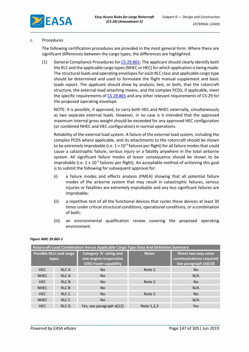
Easy Access Rules for Large Rotorcraft (CS-29) (Amendment 5)
Subpart D — Design and Construction
EXTERNAL LOADS
Powered by EASA eRules Page 147 of 305| Jun 2019
c. Procedures
The following certification procedures are provided in the most general form. Where there are significant differences between the cargo types, the differences are highlighted.
(1) General Compliance Procedures for CS 29.865: The applicant should clearly identify both the RLC and the applicable cargo types (NHEC or HEC) for which application is being made. The structural loads and operating envelopes for each RLC class and applicable cargo type should be determined and used to formulate the flight manual supplement and basic loads report. The applicant should show by analysis, test, or both, that the rotorcraft structure, the external-load attaching means, and the complex PCDS, if applicable, meet the specific requirements of CS 29.865 and any other relevant requirements of CS-29 for the proposed operating envelope.
NOTE: It is possible, if approved, to carry both HEC and NHEC externally, simultaneously as two separate external loads. However, in no case is it intended that the approved maximum internal gross weight should be exceeded for any approved HEC configuration (or combined NHEC and HEC configuration) in normal operations.
Reliability of the external load system. A failure of the external load system, including the complex PCDS where applicable, and its attachments to the rotorcraft should be shown to be extremely improbable (i.e. 1 × 10⁻⁹ failures per flight) for all failure modes that could cause a catastrophic failure, serious injury or a fatality anywhere in the total airborne system. All significant failure modes of lesser consequence should be shown to be improbable (i.e. 1 × 10⁻⁵ failures per flight). An acceptable method of achieving this goal is to submit the following for subsequent approval for:
(i) a failure modes and effects analysis (FMEA) showing that all potential failure modes of the airborne system that may result in catastrophic failures, serious injuries or fatalities are extremely improbable and any less significant failures are improbable;
(ii) a repetitive test of all the functional devices that cycles these devices at least 30 times under critical structural conditions, operational conditions, or a combination of both;
(iii) an environmental qualification review covering the proposed operating environment.
Figure AMC 29.865-1
Rotorcraft-Load Combination Versus Applicable Cargo Type Data And Definition Summary
Possible RLCs and cargo types
Category ‘A’ rating and one-engine-inoperative (OEI) hover capability
Notes Direct two-way voice communications required
See paragraph (d)(10)
HEC RLC A No Note 2 No
NHEC RLC A No N/A
HEC RLC B No Note 2 No
NHEC RLC B No N/A
HEC RLC C No Note 2 No
NHEC RLC C No N/A
HEC RLC D Yes, see paragraph d(12) Note 1,2,3 Yes

Easy Access Rules for Large Rotorcraft (CS-29) (Amendment 5)
Subpart D — Design and Construction
EXTERNAL LOADS
Powered by EASA eRules Page 148 of 305| Jun 2019
NOTES:
1. A person (or persons) being carried or transported for remuneration outside the rotorcraft can only be carried as a Class D RLC.
2. A person (or persons) who is (are) not being carried or transported for remuneration is (are) knowledgeable of the risks involved, and at some point is (are) required to be outside the rotorcraft in order to fulfil the mission. This (these) person (persons) is (are) considered to be RLC Class A, B, or C HEC as appropriate to the operation.
3. The rotorcraft is approved to the Category A engine isolation requirements of Part 29 and has a one-engine-inoperative/out-of-ground effect (OEI/OGE) hover performance capability, for the requested operating and weight envelopes, to be eligible for certification to the Class D RLC (ref.: paragraph c (12)).
4. A Class D RLC operation may be conducted with an external cargo design having a physical configuration that meets the definitions of § 1.1 for RLC Class A, B, or C.
(2) CS 29.865(a) Static Structural Substantiation Procedures: The following static structural substantiation methods should be used:
(i) Critical Basic Load Determination. The critical basic loads and corresponding flight envelope are determined by statically substantiating the gross weight range limits, the corresponding vertical limit load factors (NZW) and the safety factors applicable for the type of external load for which the application is being made.
NOTE: In cases where NHEC or HEC can have more than one shape, centre of gravity, centre of lift, or be carried at more than one distance in-flight from the rotorcraft attachment, a critical configuration for certification purposes may not be determinable. If such a critical configuration can be determined, it may be examined for approval as a ‘worst case’ to satisfy a particular certification criterion or several criteria, as appropriate. If such a critical configuration cannot be determined, the extreme points of the operational external load configuration envelope should be examined, with consideration given to any other points within the envelope that experience or any other rationale indicates as points that need to be investigated.
(ii) Vertical Limit and Ultimate Load Factors. The basic NZW is converted to the ultimate load by multiplying the maximum vertical limit load by the appropriate safety factor (for restricted category approvals, see the guidance in paragraph AC 29 MG 5). This ultimate load is used to substantiate all the existing structure affected by, and all the added structure associated with, the load-carrying device, its attachments and its cargo. Casting factors, fitting factors, and other dynamic load factors should be applied where appropriate.
(A) NHEC applications. In most cases, it is acceptable to perform a standard static analysis to show compliance. A vertical limit load factor (NZW) of 2.5 g is typical for heavy gross weight NHEC hauling configurations (ref.: CS 29.337). This vertical load factor should be applied to the maximum external load for which the application is being made, together with a minimum safety factor of 1.5.
(B) HEC applications. If a safety factor of 3.0 or more is used, it is acceptable to perform a standard static analysis to show compliance. The safety factor should be applied to the yield strength of the weakest component in the

Easy Access Rules for Large Rotorcraft (CS-29) (Amendment 5)
Subpart D — Design and Construction
EXTERNAL LOADS
Powered by EASA eRules Page 149 of 305| Jun 2019
system (QRS, complex PCDS, and attachment load path). If a safety factor of less than 3.0 is used, both an analysis and a full-scale ultimate load test of the relevant parts of the system should be performed.
Since HEC applications typically involve lower gross weight configurations, a higher vertical limit load factor is required to assure that the limit load is not exceeded in service. The applicant should use either the conservative value of 3.5 g or an analytically derived maximum vertical limit load factor for the requested operating envelope. Linear interpolation between the vertical load factors of the maximum and minimum design weights may be used. However, in no case may the vertical limit load factor be less than 2.5 g for any RLC application for HEC.
For the purpose of structural analysis or test, applicants should assume a 101.2-kg (223-pound) man as the minimum weight of each occupant carried as HEC.
NOTE: If the HEC is engaged in work tasks that employ devices of significant added weight (e.g. heavy backpacks, tools, fire extinguishers, etc.), the total weight of the 101.2-kg (223-pound) man and their equipment should be assumed in the structural analysis or test.
(iii) Critical Structural Case. For applications involving more than one RLC class or cargo type, the structural substantiation is required only for the most critical case. The most critical case should be determined by rational analysis.
(iv) Jettisonable Loads. For the substantiating analyses or tests of all jettisonable RLC external loads, including HEC, the maximum external load should be applied at the maximum angle that can be achieved in service, but not less than 30 degrees. The angle should be measured from the sling-load-line to the rotorcraft vertical axis (z axis) and may be in any direction that can be achieved in service. The 30-degree angle may be reduced in some or all directions if it is impossible to obtain due to physical constraints or operating limitations. The maximum allowable cable angle should be determined and approved. The angle approved should be based on structural requirements, mechanical interference limits, and flight-handling characteristics over the most critical conditions and combinations of conditions in the approved flight envelope.
(v) Hoist System Limit Load.
NOTE: If a hoist cable or a long-line cable is utilised, a new dynamic system is established. The characteristics of the system should be evaluated to assure that either no hazardous failure modes exist or that they are acceptably minimised. For example, the hoist cable or long-line cable may exhibit a natural frequency that could be excited by sources internal to the overall structural system (i.e. the rotorcraft) or by sources external to the system. Another example is the loading effect of the cable acting as a spring between the rotorcraft and the suspended external load.
(A) Determine the basic loads that would result in the failure or unspooling of the hoist or its installation, respectively.
NOTE: This determination should be based on static strength and any significant dynamic load magnification factors.

Easy Access Rules for Large Rotorcraft (CS-29) (Amendment 5)
Subpart D — Design and Construction
EXTERNAL LOADS
Powered by EASA eRules Page 150 of 305| Jun 2019
(B) Select the lower of the two values as the ultimate load of the hoist system installation.
(C) Divide the selected ultimate load by 1.5 to determine the true structural limit load of the system.
(D) Determine the manufacturer’s approved ‘limit design safety factor’ (or that which the applicant has applied for). Divide this factor into the true structural limit load (from (C) above) to determine the hoist system’s working (or placarded) limit load.
(E) Compare the system’s derived limit load to the applied for one ‘g’ payload multiplied by the maximum downward vertical load factor (NZWMAX) to determine the critical payload’s limit value.
(F) The critical payload limit should be equal to or less than the system’s derived limit load for the installation to be approvable.
(3) CS 29.865(b) and CS 29.865(c) Procedures for Quick-Release Systems and Cargo Hooks: for jettisonable RLCs of any applicable cargo type, both a primary quick-release system (PQRS) and a backup quick-release system (BQRS) are required. Features that should be considered are:
(i) The PQRS, BQRS and their load-release devices and subsystems (such as electronically actuated guillotines) should be separate (i.e. physically, systematically, and functionally redundant).
(ii) The controls for the PQRS should be installed on one of the pilot’s primary controls, or in an equivalently accessible location. The use of an ‘equivalent accessible location’ should be reviewed on a case-by-case basis and utilised only where equivalent safety is clearly maintained.
(iii) The controls for the BQRS may be less sophisticated than those of the PQRS. For instance, manual cable cutters are acceptable provided they are listed in the flight manual as a required device and have a dedicated, placarded storage location.
(iv) The PQRS should release the external load in less than 5 seconds. The BQRS should release the external load in less than 30 seconds. This time interval begins the moment an emergency is declared and ends when the load is released.
(v) Each quick-release device should be designed and located to allow the pilot or a crew member to accomplish external cargo release without hazardously limiting the ability to control the rotorcraft during emergency situations. The flight manual should reflect the requirement for a crew member and their related functions.
(vi) Other Load Release Types. In some current configurations, such as those used for high line operations, a load release may be present that is not on the rotorcraft but is on the complex PCDS itself. Examples are a tension release device that lets out line under an operationally induced load or a personal rope cutter. These devices are acceptable if:
(A) the off-rotorcraft release is considered to be a ‘third release’. This type of release is not a substitute for a required release (i.e. PQRS or BQRS);
(B) the release meets all other relevant requirements of CS 29.865 and the methods of this AMC or equivalent methods; and

Easy Access Rules for Large Rotorcraft (CS-29) (Amendment 5)
Subpart D — Design and Construction
EXTERNAL LOADS
Powered by EASA eRules Page 151 of 305| Jun 2019
(C) the release has no operational or failure modes that would affect continued safe flight and landing under any operations, critical failure modes, conditions, or combination of either.
(vii) Cargo Hooks or Equivalent Devices and their Related Systems. All cargo hooks or equivalent devices should be approved to acceptable aircraft industry standards. The applicant should present these standards, and any related manufacturer’s certificates of production or qualification, as part of the approval package.
(A) General. Cargo hook systems should have the same reliability goals and should be functionally demonstrated under the critical loads for NHEC and HEC, as appropriate. All engagement and release modes should be demonstrated. If the hook is used as a quick-release device, then the release of critical loads should be demonstrated under conditions that simulate the maximum allowable bank angles and speeds and any other critical operating conditions. Demonstration of any re-latching features and any safety or warning devices should also be conducted. Demonstration of actual in-flight emergency quick-release capability may not be necessary if the quick-release capability can be acceptably simulated by other means.
NOTE 1: Cargo hook manufacturers specify particular shapes, sizes, and cross sections for lifting eyes to assure compatibility with their hook design (e.g. Breeze Eastern Service Bulletin CAB-100-41). Experience has shown that, under certain conditions, a load may inadvertently hang up because of improper geometry at the hook-to-eye interface that will not allow the eye to slide off an open hook as intended.
NOTE 2: For both NHEC and HEC designs, the phenomenon of hook dynamic roll-out (inadvertent opening of the hook latch and subsequent release of the load) should be considered to assure that QRS reliability goals are not compromised. This is of particular concern for HEC applications. Hook dynamic roll-out occurs during certain ground-handling and flight conditions that may allow the lifting eye to work its way out of the hook.
Hook dynamic roll-out typically occurs when either the RLC’s sling or harness is not properly attached to the hook, is blown by down draft, is dragged along the ground or through water, or is otherwise placed into a dangerous hook-to-eye configuration.
The potential for hook dynamic roll-out can be minimised in design by specifying particular hook-and-eye shape and cross-section combinations. For non-jettisonable RLCs, a pin can be used to lock the hook-keeper in place during operations.
NOTE: Some cargo hook systems may employ two or more cargo hooks for safety. These systems are approvable. However, a loss of any load by a single hook should be shown to not result in a loss of control of the rotorcraft. In a dual hook system, if the hook itself is the quick-release device (i.e. if a single release point does not exist in the load path between the rotorcraft and the dual hooks), the pilot should have a dual PQRS that includes selectable, co-located individual quick releases that are independent for each hook used. A BQRS should also be present for each hook. For cargo hook systems with more than two hooks, either a single release point should be present in the

Easy Access Rules for Large Rotorcraft (CS-29) (Amendment 5)
Subpart D — Design and Construction
EXTERNAL LOADS
Powered by EASA eRules Page 152 of 305| Jun 2019
load path between the rotorcraft and the multiple hook system, or multiple PQRSs and BQRSs should be present.
(B) Jettisonable Cargo Hook Systems. For jettisonable applications, each cargo hook:
(1) should have a sufficient amount of slack in the control cable to permit cargo hook movement without tripping the hook release;
(2) should be shown to be reliable.
(3) For HEC systems, unless the cargo hook is to be the primary quick-release device, each cargo hook should be designed so that operationally induced loads cannot inadvertently release the load. For example, a simple cargo hook should have a one-way, spring-loaded gate (i.e. ‘snap hook’) that allows load attachment going into the gate but does not allow the gate to open (and subsequently lose the HEC) when an operationally induced load is applied in the opposite direction. For HEC applications, cargo hooks that also serve as quick-release devices should be carefully reviewed to assure they are reliable.
(4) CS 29.865(b)(3) Reliability Determination for QRSs and Devices: QRSs are required to be reliable. The primary electrical and mechanical failure modes that should be identified and minimised are: (1) load release by any means, and (2) loss of continued safe flight and landing capability due to a QRS failure. However, any failure that could result in catastrophic failure modes, serious injuries or fatalities should also be identified and shown to be extremely improbable. All other failure modes should be shown to be improbable. The reliability of each QRS system should be demonstrated by completion and approval of all of the following:
(i) An FMEA showing that all potential failure modes of the QRS which may result in catastrophic failures, serious injuries or fatalities are extremely improbable and any less-significant failures are improbable.
(ii) A repetitive test of all functioning devices that affect or comprise the QRS, which tests all the critical conditions or combinations of critical conditions at least 10 times each for NHEC and 30 times each for HEC, using both the primary and backup quick-release subsystems.
(iii) An environmental qualification programme that includes consideration of high and low temperatures (typically – 40 °C (–40 °F) to + 65.6 °C (+ 150 °F)), altitudes up to 12 000 feet, humidity, salt spray, sand and dust, vibration, shock, rain, fungus, and acceleration. Testing should be conducted in accordance with RTCA/DO-160 or MIL-STD-810 for high- and low-temperature tests and for vibrations.
(iv) Using the methods of compliance in other relevant paragraphs of AC 29-2C including where supplemented and amended by CS-29 Book 2 or equivalent methods.
(5) Functional Reliability and Durability Compliance Procedures for Hoist Systems under CS 29.865(b)(3)(i) and (c)(2): hoist systems and their installations in the rotorcraft should be designed, approved, and demonstrated as follows:
(i) Reserved
(ii) Reserved

Easy Access Rules for Large Rotorcraft (CS-29) (Amendment 5)
Subpart D — Design and Construction
EXTERNAL LOADS
Powered by EASA eRules Page 153 of 305| Jun 2019
(iii) It is assumed that only one hoist cycle will typically occur per flight. This rationale has been used to determine the requirement for 10 demonstration cycles for NHEC applications and 30 demonstration cycles for HEC applications. However, if a particular application requires more than one hoist cycle per flight, then the number of demonstration cycles should be increased accordingly.
(iv) The hoist or rescue hook system should be reliable for the phases of flight in which it is operable, unstowed, partially unstowed, or in which cargo is carried. The hoist should be disabled (or an overriding, fail-safe mechanical safety device such as either a flagged removable shear pin or a load-lowering brake should be utilised) to prevent inadvertent load unspooling or release during any extended flight phases in which hoist operation is not intended. Loss of hoist operational control should also be considered. The reliability of the system should be demonstrated by completion and approval of all of the following:
(A) An FMEA showing that all potential failure modes of the hoist or rescue hook system which may result in catastrophic failures, serious injuries or fatalities are extremely improbable and any less-significant failures are improbable.
(B) Unless a more rational test method is presented and approved, at least 10 repetitive tests of all functional devices, which exercise the entire system’s functional parameters, should be conducted. These repetitive tests may be conducted on the rotorcraft, or by using a bench simulation that accurately replicates the rotorcraft installation.
(C) A hoist unit environmental qualification programme that includes consideration of high and low temperatures (typically – 40 °C (– 40 °F) to + 65.6 °C (+ 150 °F)), altitudes up to 12 000 feet, humidity, salt spray, sand and dust, vibration, shock, rain, fungus, and acceleration. Testing in accordance with RTCA/DO-160 or MIL-STD-810 for high- and low-temperature tests and for vibrations. Hoist manufacturers should submit a test plan and follow-on test reports to the applicant and the authority following the completion of the qualification. It is intended that the hoist itself either be prequalified to the EMI and lightning threat levels specified for NHEC or HEC, as applicable for the requested operation, or that it be qualified as part of the entire on-board QRS to these threat levels.
(D) All instructions and documents necessary for continued airworthiness, normal operations, and emergency operations.
(v) Cable Attachment. Either the cable should be positively attached to the hoist drum and the attachment should have ultimate load capability, or equivalent means should be provided to minimise the possibility of inadvertent, complete cable unspooling.
(vi) Cable Length and Marking. A length of the cable nearest to the cable’s attachment to the hoist drum should be visually marked to indicate to the operator that the cable is near to its full extension. The length of cable to be marked is a function of the maximum extension speed of the system and the operator’s reaction time needed to prevent cable run-out. It should be determined during certification demonstration tests. In no case should the length be less than 3.5 drum circumferences.
(vii) Cable Stops. Means should be present to automatically stop cable movement quickly when the system’s extension and retraction operational limits are reached.
Easy Access Rules for Large Rotorcraft (CS-29) (Amendment 5)
Subpart D — Design and Construction
EXTERNAL LOADS
Powered by EASA eRules Page 154 of 305| Jun 2019
(viii) Hoist System Load-Speed Combination Ground Tests. The load versus speed combinations of the hoist should be demonstrated on the ground (either using anaccurate engineering mock-up or a rotorcraft) by showing the repeatability of the no load-speed combination, the 50 per cent load-speed combination, the 75 per cent load-speed combination and the 100 per cent (i.e. system-rated limit) load-speed combination. If more than one operational speed range exists, the preceding tests should be performed at either all speeds or at the most critical speed.
(A) At least 1/10 of the demonstration cycles (see definition) should include the maximum aft angular displacement of the load from the drum, applied for under CS 29.865(a).
(B) A minimum of 6 consecutive, complete operation cycles should be conducted at the system’s 100 per cent (i.e. system limit rated) load-speed combination.
(C) In addition, the demonstration should cover all normal and emergency modes of intended operation and should include operation of all control devices such as limit switches, braking devices, and overload sensors in the system.
(D) All quick-release devices and cable cutters should be demonstrated at 0, 25, 50, 75 and 100 per cent of the system limit load or at the most critical percentage value.
NOTE: Some hoist designs have built-in cable-tensioning devices that function at the no load-speed combination, as well as at other load-speed combinations. These devices should be shown to work during the no load-speed and other load-speed cable-cutting demonstrations.
(E) All electrical and mechanical systems and load-release devices for any jettisonable NHEC or HEC RLC should be shown to be reliable by both analysis and testing.
(F) Any devices or methods used to increase the mechanical advantage of the hoist should also be demonstrated.
(G) During a portion of each demonstration cycle, the hoist should be operated from each station from which it can be controlled.
NOTE: A reasonable amount of starting and stopping during demonstration cycles is acceptable.
(ix) Hoist System Continued Airworthiness. The design life of the hoist system and any life-limited components should be clearly identified, and the Airworthiness Limitations Section of the maintenance manual should include these requirements. For STCs, a maintenance manual supplement should be provided that includes these requirements.
NOTE: Design lives of hoist and cable systems are typically between 5 000 and 8 000 cycles. Some hoist systems have usage time meters installed. Others may have cycle counters installed. Cycle counters should be considered for HEC operations and high-load or other operations that may cause low-cycle fatigue failures.

Easy Access Rules for Large Rotorcraft (CS-29) (Amendment 5)
Subpart D — Design and Construction
EXTERNAL LOADS
Powered by EASA eRules Page 155 of 305| Jun 2019
(x) Hoist System Flight Tests. An in-flight demonstration test of the hoist system should be conducted for helicopters designed to carry NHEC or HEC. The rotorcraft should be flown to the extremes of the applicable manoeuvre flight envelope and to all conditions that are critical to strength, manoeuvrability, stability, and control, or any other factor affecting airworthiness. Unless a lesser load is determined to be more critical for either dynamic stability or other reasons, the maximum hoist system rated load or, if less, the maximum load requested for approval (and the associated limit load data placards) should be used for these tests. The minimum hoist system load (or zero load) should also be demonstrated in these tests.
(6) CS 29.865(b)(3)(ii) Electromagnetic Interference: protection of the QRS against potential internal and external sources of electromagnetic interference (EMI) and lightning is required. This is necessary to prevent inadvertent load releases from sources such as lightning strikes, stray electromagnetic signals, and static electricity.
(i) Jettisonable NHEC systems should be able to absorb a minimum of 20 volts per metre (i.e. CAT U) radio frequency (RF) field strength per RTCA/DO-160.
(ii) Jettisonable HEC systems should be able to absorb a minimum of 200 volts per metre (i.e. CAT Y) RF field strength per RTCA/DO-160.
NOTE 1: These RF field threat levels may need to be increased for certain special applications such as microwave tower and high-voltage high line repairs. Separate criteria for special applications under the regulations of more than one agency or entity (such as the Institute of Electrical and Electronics Engineers (IEEE) or Occupational Safety and Health Administration (OSHA) standards) should also be addressed, as applicable, during certification. When necessary, the issue paper process can be used to establish a practicable level of safety for specific high-voltage or other special application conditions. For any devices or means added to meet the regulations of more than one agency or entity, their failure modes should not have an adverse effect on flight safety. Other certification authorities may require higher RF field threat levels than those required by CS 29.865 (e.g. CS-29 Appendix E).
NOTE 2: An approved standard rotorcraft test that includes the full HIRF frequency and amplitude external and internal environments on the QRS and complex PCDS (or the entire rotorcraft including the QRS and complex PCDS) could be substituted for the jettisonable NHEC and HEC systems tests defined by c(6)(i) and c(6)(ii) respectively, as long as the RF field strengths directly on the QRS and complex PCDS are shown to equal or exceed those of c(6)(i) and c(6)(ii).
NOTE 3: The EMI levels specified in c(6)(i) and c(6)(ii) are total EMI levels to be applied to the QRS (and affected QRS component) boundary. The total EMI level applied should include the effects of both external and internal EMI sources. All aspects of internally generated EMI should be carefully considered including peaks that could occur from time to time due to any combination of on-board systems being operated. For example, special attention should be given to EMI from hoist operations that involve the switching of very high currents. Those currents can generate significant voltages in closely spaced wiring that, if allowed to reach some squib designs, could activate the device. Shielding, bonding and grounding of wiring associated with the operation of the hoist and the quick-release mechanism should be clearly and adequately evaluated in design and certification. This evaluation may require testing. One acceptable test method to demonstrate the adequacy of QRS shielding, bonding and grounding would be to actuate the hoist under maximum load together with likely critical combinations of other aircraft electrical loads

Easy Access Rules for Large Rotorcraft (CS-29) (Amendment 5)
Subpart D — Design and Construction
EXTERNAL LOADS
Powered by EASA eRules Page 156 of 305| Jun 2019
and demonstrate that the test squibs (which are more EMI sensitive than the squibs specified for use in the QRS) do not inadvertently operate during the test.
(7) CS 29.865(c)(1) QRS Requirements for Jettisonable HEC Operations: For jettisonable HEC operations, both the PQRS and BQRS are required to have a dual actuation device (DAD) for external cargo release. Two distinct actions are required to minimise inadvertent jettison of HEC. The DAD is intended for emergency use during the phases of flight that the HEC is carried or retrieved. The DAD can be used for both NHEC and HEC operations. However, because it can be used for HEC, the Instructions for Continued Airworthiness should be carefully reviewed and documented. The DAD can be operated by the pilot from a primary control or, after a command is given by the pilot, by a crew member from a remote location. If the backup DAD is a cable cutter, it should be properly secured, placarded and readily accessible to the crew member intended to use it.
(8) CS 29.865(c)(2) PCDS: for all HEC applications that use complex PCDSs, an approval is required. The complex PCDS may be either previously approved or is required to be approved during certification. In either case, its installation should be approved. The complex PCDS is required to be reliable. The failure of the complex PCDS, and its attachments to the rotorcraft, should be shown to be extremely improbable (i.e. 1 × 10⁻⁹ failures per flight) for all failure modes that could cause a catastrophic failure, serious injury or fatality. All significant failure modes of lesser consequence should be shown to be improbable (i.e. 1 × 10⁻⁵ failures per flight). An acceptable method of achieving this goal is to submit the following for subsequent approval:
(i) a failure modes and effects analysis (FMEA) showing that all the potential failure modes of the complex PCDS that may result in catastrophic failures, serious injuries or fatality, are extremely improbable and any less-significant failures are improbable.
(ii) a repetitive test of all functional devices that cycles these devices at least 30 times under critical structural conditions, operational conditions, or a combination.
(iii) an environmental qualification review of the proposed operating environment.
NOTE: Complex PCDS designs can include relatively complex devices such as multiple occupant cages or gondolas. The purpose of the PCDS is to provide a minimum acceptable level of safety for personnel being transported outside the rotorcraft. The personnel being transported may be healthy or injured, conscious or unconscious.
(iv) Regulation (EU) No 965/2012 on Air Operations contains the minimum performance specifications and standards for simple PCDSs, such as HEC body harnesses.
(v) Static Strength. The complex PCDS should be substantiated for the allowable ultimate load and loading conditions as determined under paragraph c(2).
(vi) Fatigue. CS 29.865(f) requires the metallic components of the complex PCDSs to be substantiated for fatigue in accordance with CS 29.571 (ref.: c (14)).
(vii) Personnel Safety. For each complex PCDS design, the applicant should submit a design evaluation that assures the necessary level of personnel safety is provided. As a minimum, the following should be evaluated.
(A) The complex PCDS should be easily and readily entered or exited.

Easy Access Rules for Large Rotorcraft (CS-29) (Amendment 5)
Subpart D — Design and Construction
EXTERNAL LOADS
Powered by EASA eRules Page 157 of 305| Jun 2019
(B) It should be placarded with its proper capacity, the internal arrangement and location of occupants, and ingress and egress instructions.
(C) For door latch fail-safety, more than one fastener or closure device should be used. The latch device design should provide direct visual inspectability to assure it is fastened and secured.
(D) Any fabric used should be durable and should be at least flame-resistant.
(E) Reserved
(F) Occupant retention devices and the related design safety features should be used as necessary. In simple designs, rounded corners and edges with adequate strapping (or other means of HEC retention relative to the complex PCDS) and head supports or pads may be all the safety features that are necessary. Complex PCDS designs may require safety features such as seat belts, handholds, shoulder harnesses, placards, or other personnel safety standards.
(viii) EMI and Lightning Protection. All essential, affected components of the complex PCDS, such as intercommunication equipment, should be protected against RF field strengths to a minimum of RTCA/DO-160 CAT Y.
(ix) Instructions for Continued Airworthiness. All instructions and documents necessary for continued airworthiness, normal operations and emergency operations should be completed, reviewed and approved during the certification process.
(x) Flotation Devices. Complex PCDSs that are intended to have a dual role as flotation devices or life preservers should meet the relevant requirements for ‘Life Preservers’. Also, any complex PCDS design to be used in the water should have a flotation kit. The flotation kit should support the weight of the maximum number of occupants and the complex PCDS in the water and minimise the possibility of the occupants floating face down.
(xi) Aerodynamic Considerations. Some complex PCDS designs may spin, twist or otherwise respond unacceptably in flight. Each of these designs should be structurally restrained with a device such as a spider, a harness, or an equivalent device to minimise undesirable flight dynamics.
(xii) Medical Design Considerations. Complex PCDSs should be designed to the maximum practicable extent and placarded to maximise the HEC’s protection from medical considerations such as blocked air passages induced by improper body configurations and excessive losses of body heat during operations. Injured or water-soaked persons may be exposed to high body heat losses from sources such as rotor washes and airstreams. The safety of occupants of complex PCDSs from transit-induced medical considerations can be greatly increased by proper design.
(9) CS 29.865(c)(3) QRS Design, Installation and Placarding: for jettisonable HEC applications, the QRS design, installation and associated placarding should be given special consideration to assure the proper level of occupant safety.
(10) CS 29.865(c)(4) Intercom Systems for HEC Operations: for all HEC operations, the rotorcraft is required to be equipped for, or otherwise allow, direct intercommunication under any operational conditions among crew members and the HEC. For some systems, voice or hand signals to PCDS occupants may be acceptable. For other systems and for
Easy Access Rules for Large Rotorcraft (CS-29) (Amendment 5)
Subpart D — Design and Construction
EXTERNAL LOADS
Powered by EASA eRules Page 158 of 305| Jun 2019
RCL Class D operations, more sophisticated devices such as two-way radios or intercoms should be employed.
(11) CS 29.865(c)(5) Flight Manual Procedures: appropriate flight manual procedures and limitations for all HEC operations should be presented. All limitations are required to be approved for all RLCs of Class A, B, or C that employ HEC. The flight manual should clearly define the method of communication between the flight crew and the HEC. These instructions and manuals should be validated during flight testing.
(12) CS 29.865(c)(6) Limitations for HEC Operations: for jettisonable HEC operations, a rotorcraft may be required by operations requirements to meet the Category A engine isolation requirements of CS-29 and to have one-engine-inoperative/out-of-ground effect (OEI/OGE) hover performance capability in its approved, jettisonable HEC weight, altitude, and temperature envelope.
(i) In determining OEI hover performance, dynamic engine failures should be considered. Each hover verification test should begin from a stabilised hover at the maximum OEI hover weight, at the requested in-ground-effect (IGE) or OGE skid or wheel height, and with all engines operating. At this point, the critical engine should be failed and the aircraft should remain in a stabilised hover condition without exceeding any rotor limits or engine limits for the operating engine(s). As with all performance testing, engine power should be limited to the minimum specification power. Engine failures may be simulated by rapidly moving the throttle to idle provided a ‘needle split’ is obtained between the rotor and engine RPM.
(ii) Normal pilot reaction time should be used, following the engine failure, to maintain the stabilised hover flight condition. When hovering OGE or IGE at the maximum OEI hover weight, an engine failure should not result in an altitude loss of more than 10 per cent or 4 feet, whichever is greater, of the altitude established at the time of engine failure. In either case, a sufficient power margin should be available from the operating engine(s) to regain the altitude lost during the dynamic engine failure and to transition to forward flight.
(iii) Consideration should also be given to the time required to recover (winch up and bring aboard) the Class D external load and to transition to forward flight. This time increment may limit the use of short-duration OEI power ratings. For example, for a helicopter that sustains an engine failure at a height of 40 feet, the time required to re-stabilise in a hover, recover the external load (given the hoist speed limitations), and then transition to forward flight (with minimal altitude loss) would likely preclude the use of the 30-second engine ratings and may encroach upon the 2 ½-minute ratings. Such an encroachment into the 2 ½-minute ratings is not acceptable.
(iv) For helicopters that incorporate engine-driven generators, the hoist should remain operational following an engine or generator failure. A hoist should not be powered from a bus that is automatically shed following the loss of an engine or generator. Maximum two-engine generator loads should be established so that when one engine or generator fails, the remaining generator can assume the entire rotorcraft electrical load (including the maximum hoist electrical load) without exceeding the approved limitations.
(v) The rotorcraft flight manual (RFM) should contain information that describes the expected altitude loss, any special recovery techniques, and the time increment

Easy Access Rules for Large Rotorcraft (CS-29) (Amendment 5)
Subpart D — Design and Construction
EXTERNAL LOADS
Powered by EASA eRules Page 159 of 305| Jun 2019
used for recovery of the external load when establishing maximum weights and wheel or skid heights. The OEI hover chart should be placed in the performance section of the RFM or RFM supplement. The allowable altitude extrapolation for the hover data should not exceed 2 000 feet.
(13) CS 29.865(d) Flight Test Verification Work: flight test verification work (or an equivalent combination of analysis and ground testing, either in conjunction with or in addition to operating rules such as Regulation (EU) No 965/2012 on Air Operations) that thoroughly examines the operational envelope should be conducted with the external cargo carriage device for which approval is requested (especially those that involve HEC). The flight test programme should show that all aspects of the operations applied for are safe, uncomplicated, and can be conducted by a qualified flight crew under the most critical service environment and, in the case of HEC, under emergency conditions. Flight tests should be conducted for the simulated representative NHEC and HEC loads to demonstrate their in-flight handling and separation characteristics. Each placard, marking and flight manual supplement should be validated during flight testing.
(i) General. Flight testing (or an equivalent combination of analysis and testing) should be conducted under the critical combinations of configurations and operating conditions for which basic type certification approval is sought. Additional combinations of external loads and operating conditions may be subsequently approved under the relevant operational requirements as long as the structural limits and reliability considerations of the basic certification approval are not exceeded (i.e. equivalent safety is maintained). The qualification flight test work of this subparagraph is intended to be accomplished primarily by analysis or bench testing. However, at least one in-flight limit load drop test should be conducted for the critical load case. If one critical load case cannot be clearly identified, then more than one drop test might be necessary. Also, in-flight tests for the minimum load case (i.e. typically the cable hook itself) with the load trailing both in the minimum and maximum cable length configurations should be conducted. Any safety-of-flight limitations should be documented and placed in the rotorcraft flight manual (RFM). In certain low gross weight, jettisonable HEC configurations, the complex PCDS may act as a trailing aerofoil that could result in entangling the complex PCDS and the rotorcraft. These configurations should be assessed on a case-by-case basis by analysis or flight test to assure that any safety-of-flight limitations are clearly identified and placed in the RFM.
(ii) Separation Characteristics of Jettisonable External Loads. For all jettisonable RLCs of any applicable cargo type, the satisfactory post-jettison separation characteristics of all loads should meet the following minimum criteria:
(A) Immediate ‘clean’ operation of the QRS, including ‘clean’ separate functioning of the PQRS and BQRS.
(B) No damage to the helicopter during or following actuation of the QRS and load jettisoning.
(C) A jettison trajectory clear of the helicopter.
(D) No inherent instability of the jettisonable (or just jettisoned) HEC or NHEC while in proximity to the helicopter.
(E) No adverse or uncontrollable helicopter reactions at the time of jettison.

Easy Access Rules for Large Rotorcraft (CS-29) (Amendment 5)
Subpart D — Design and Construction
EXTERNAL LOADS
Powered by EASA eRules Page 160 of 305| Jun 2019
(F) Stability and control characteristics after jettison should be within the originally approved limits.
(G) No unacceptable degradation of the helicopter performance characteristics after jettison.
(iii) Jettison Requirements for Jettisonable External Loads. For representative cargo types (low-, medium- and high-density loads on long and short lines), emergency and normal jettison procedures should be demonstrated (by a combination of analysis, ground tests, and flight tests) at sufficient combinations of flight conditions to establish a jettison envelope that should be placed in the RFM.
(iv) QRS Demonstration. Repetitive jettison demonstrations should be conducted that use the PQRS. The BQRS should be utilised at least once.
(v) QRS Reliability (i.e. failure modes) Affecting Flight Performance. The FMEA of the QRS (ref.: c (4)) should show that no single system failure will result in unsatisfactory flight characteristics, including any QRS failures that result in asymmetric loading conditions.
(vi) Flight Test Weight and CG Locations. All flight tests should be conducted at the extreme or critical combinations of weight and longitudinal and lateral CG conditions within the flight envelope that is applied for. The rotorcraft should remain within the approved weight and CG limits both with the external load applied and after jettison of the load.
(vii) Jettison Envelopes. Emergency and normal jettison demonstrations should be performed at sufficient airspeeds and decent rates to establish any restrictions for satisfactory separation characteristics. Both the maximum and minimum airspeed limits and the maximum descent rate for safe separation should be determined. The sideslip envelope as a function of airspeed should be determined.
(viii) Altitude. Emergency and normal jettison demonstrations should be performed at altitudes consistent with the approvable operational envelope and with the manoeuvring requirements necessary to overcome any adverse effects of the jettison.
(ix) Attitude. Emergency and normal jettison demonstrations should be performed from all attitudes appropriate to normal and emergency operational usage. Where the attitudes of HEC or NHEC with respect to the helicopter may vary, the most critical attitude should be demonstrated. This demonstration would normally be accomplished by bench testing.
(x) Hoist and Rescue Hook Systems or Cargo Hook Systems. An in-flight demonstration test of the hoist system should be conducted for helicopters designed to carry NHEC or HEC. The rotorcraft should be flown to the extremes of the applicable manoeuvre flight envelope and to all conditions that are critical to strength, manoeuvrability, stability, and control, or any other factor affecting its airworthiness. Unless a lesser load is determined to be more critical for either dynamic stability or other reasons, the maximum hoist system rated load or, if less, the maximum load requested for approval (and the associated limit load data placards) should be used for these tests. The minimum hoist system load (or zero load) should also be demonstrated in these tests.

Easy Access Rules for Large Rotorcraft (CS-29) (Amendment 5)
Subpart D — Design and Construction
EXTERNAL LOADS
Powered by EASA eRules Page 161 of 305| Jun 2019
(14) CS 29.865(e) External Loads Placards and Markings: placards and markings should be installed next to the external-load attaching means, in a clearly noticeable location, that state the primary operational limitations — specifically including the maximum authorised external load. Not all operational limitations need be stated on the placard (or equivalent markings); only those that are clearly necessary for immediate reference in operations. Other more detailed operational limitations of lesser immediate importance should be stated either directly in the RFM or in an RFM supplement.
(15) CS 29.865(f) Fatigue Substantiation: the fatigue evaluation of CS 29.571 should be applied as follows:
NOTE: The term ‘hazard to the rotorcraft’ is defined to include all hazards to either the rotorcraft, to the occupants thereof, or both.
(i) Fatigue Evaluation of NHEC Applications. Any critical components of the suspended system and their attachments (such as the cargo hook or bolted or pinned truss attachments), the failure of which could result in a hazard to the rotorcraft, should undergo an acceptable fatigue analysis in accordance with AC 27 MG 11, paragraph e.
(ii) Fatigue Evaluation of HEC Applications. The entire complex PCDS and its attachments should be reviewed on a component-by-component basis to determine which components, if any, are fatigue-critical or damage-intolerant. These components should be analysed or tested (per AC 27 MG 11, AC 29 MG 11, or other equivalent methods) to assure their fatigue life limits are properly determined and placed in the limited life section of the maintenance manual.
(16) Other Considerations
(i) Agricultural Installations (AIs): AIs can be approved for either jettisonable or non-jettisonable NHEC or HEC operations as long as they meet relevant certification and operations requirements and follow appropriate compliance methods. However, most current AI designs are external fixtures (see definition), not external loads. External fixtures are not approvable as jettisonable external cargo because they do not have a true payload (see definition), true jettison capability (see definition), or a complete QRS. Many AI designs can dump their solid or liquid chemical loads by use of a ‘purge port’ release over a relatively long time period (i.e. greater than 30 seconds). This is not considered to be a true jettison capability (see definition) since the external load is not released by a QRS and since the release time span is typically greater than 30 seconds (ref.: b(20) and c(7)). Thus, these types of AIs should be approved as non-jettisonable external loads. However, other designs that have the entire AI (or significant portions thereof) attached to the rotorcraft, that have short time frame jettison (or release) capabilities provided by QRSs that meet the definitions herein and that have no post-jettison characteristics that would endanger continued safe flight and landing may be approved as jettisonable external loads. For example, if all the relevant criteria are properly met, a jettisonable fluid load can be approved as an NHEC external cargo. AC 29 MG 5 discusses other AI certification methodologies.
(ii) External Tanks: external tank configurations that have true payload (see definition) and true jettison capabilities (see definition) should be approved as jettisonable NHEC. External tank configurations that have true payload capabilities but do not have true jettison capabilities should be approved as non-jettisonable NHEC. An external tank that has neither a true payload capability nor true jettison capability
Easy Access Rules for Large Rotorcraft (CS-29) (Amendment 5)
Subpart D — Design and Construction
EXTERNAL LOADS
Powered by EASA eRules Page 162 of 305| Jun 2019
is an external fixture; it should not be approved as an external load under CS 29.865. If an external tank is to be jettisoned in flight, it should have a QRS that is approved for the maximum jettisonable external tank payload and is either inoperable or is otherwise rendered reliable to minimise inadvertent jettisons above the maximum jettisonable external tank payload.
(iii) Logging Operations: These operations are very susceptible to low-cycle fatigue because of the large loads and relatively high load cycles that are common to this industry. It is recommended that load-measuring devices (such as load cells) be used to assure that no unrecorded overloads occur and to assure that cycles producing high fatigue damage are properly considered. Cycle counters are recommended to assure that acceptable cumulative fatigue damage levels are identifiable and are not exceeded. As either a supplementary method or an alternate method, maintenance instructions should be considered to assure proper cycle counting and load recording during operations.
(17) Reserved
(18) Instructions for Continued Airworthiness. Maintenance manuals (and RFM supplements) developed by applicants for external load applications should be presented for approval and should include all appropriate inspection and maintenance procedures. The applicant should provide sufficient data and other information to establish the frequency, extent, and methods of inspection of critical structures, systems and components. This information is required by CS 29.1529 to be included in the maintenance manual. For example, maintenance requirements for sensitive QRS squibs should be carefully determined, documented, approved during certification, and included as specific mandatory scheduled maintenance requirements that may require either ‘daily’ or ‘pre-flight’ checks (especially for HEC applications).
[Amdt No: 29/5]
AMC No 2 to 29.865 External loads operations using simple personnel-carrying device systems
ED Decision 2018/007/R8/007/R
If required by the applicable operating rule or if an applicant elects to, this AMC provides a means of compliance for the airworthiness certification of a simple personnel-carrying device system (PCDS) and attaching means to the hook, providing safety factors and consideration of calendar life replacement limits in lieu of a dedicated fatigue analysis and test.
A PCDS is considered to be simple if:
(a) it meets an EN standard under EC Directive 89/686/EEC, or Regulation (EU) 2016/425, as applicable, or subsequent revision;
(b) it is designed to restrain no more than a single person (e.g. hoist or cargo hook operator, photographer, etc.) inside the cabin, or to restrain no more than two persons outside the cabin;
(c) it is not a rigid structure such as a cage, a platform or a basket.
PCDSs that cannot be considered to be simple are considered to be complex.

Easy Access Rules for Large Rotorcraft (CS-29) (Amendment 5)
Subpart D — Design and Construction
EXTERNAL LOADS
Powered by EASA eRules Page 163 of 305| Jun 2019
Note 1: EASA or the relevant Authority should be contacted to confirm the classification in the event that:
— a PCDS includes new or novel features;
— a PCDS has not been proven by appreciable and satisfactory service experience; or
— there is any doubt in the classification.
Approval of Simple PCDSs
If the approval of a simple PCDS is requested, then Directive 89/686/EEC, or Regulation (EU) 2016/425 are an acceptable basis for the certification of a simple PCDS provided that:
(a) the applicable Directive 89/686/EEC or Regulation (EU) 2016/425, as applicable, or subsequent revision and corresponding EN standards for the respective components are complied with (EC Type Examination Certificate);
(b) the applicant for the minor change has obtained from the manufacturer and keeps on record the applicable EC Conformity Certificate(s).
Note 2: A simple PCDS has an EC Type Examination Certificate (similar to an STC), issued by a Notified Certification Body and, for the production and marketing, an EC Conformity Certificate (similar to an EASA Form 1) issued by the manufacturer.
Note 3: In cases where ropes or elements connect simple PCDSs to the hoist/cargo hook or internal helicopter cabin, the EN certification can be achieved by a body meeting the transposition into national law of the applicable EC/EU regulation.
The EC-certified components are appropriately qualified for the intended use and the environmental conditions.
Note 4: The intended use and corresponding risks must be considered when selecting EN standards. For example hoist operators and rescuers that have to work at the edge of the cabin or outside should have full body harnesses to address the risk of inversion. Litters and the corresponding restraint systems should be adequately designed for the loads that can be generated during spinning.
Note 5: The assembly of the different components should also consider the intended use. For example the attachment of the tethering strap to the harness of a hoist operator should be of a quick-release type to allow quick detachment from the aircraft following a ditching or emergency landing. The tethering strap should also be adjustable to take up slack and avoid shock loads being transmitted to other components.
(c) The maximum load applied to each component between the HEC and the hook is conservatively estimated. This is particularly important when more than one person is attached by a single system to the cargo hook/ hoist. Appendix 1 defines the appropriate minimum ultimate load (ULmin). If ULmin is above the static strength currently declared by the supplier of the PCDS or of a component of the attachments, through compliance with an EN standard, then proof of sufficient strength is to be provided by static tests. All possible service load cases (including asymmetric load distribution) are to be considered. In this case, the PCDS and/or the attaching means (e.g. rope, carabineer, shackles, etc.) must be capable of supporting ULmin for a minimum of 3 minutes without failure. There should be no deformation of components that could allow the release of the HEC. Components and details added to the EN-approved equipment (such as splicing, knots, stitching, seams, press fits, etc.) or the materials used (textiles, composites, etc.) that might reduce the strength of a product or could (in combination) have other detrimental effects have been investigated by the applicant and accounted for in the substantiation.

Easy Access Rules for Large Rotorcraft (CS-29) (Amendment 5)
Subpart D — Design and Construction
EXTERNAL LOADS
Powered by EASA eRules Page 164 of 305| Jun 2019
(d) The effects of ageing (due to sunlight, temperature, water immersion, etc.) and other operational factors that may affect the strength of the PCDS are accounted for through appropriate inspections and the application of a calendar life limit as appropriate. The PCDS and the related attachment elements are limited to the carriage of HEC.
(e) The risk of fatigue failure is minimised. See section below for further details.
(f) Instructions for Continued Airworthiness (ICA) should be provided. Typically, the ICA would comprise an inspection programme and maintenance instructions based on the applicable manufacturer’s data. The ICA should ensure that specific operational uses of the system that might affect its strength are accounted for. A calendar life limit should be applied when appropriate.
(g) When the harness is not designed to transport an incapacitated or untrained person, then the labelling and/or the user/flight manual should include a specific limitation of use as applicable.
Note 6: The following considerations and corresponding instructions/limitations should be taken for EN 1498 Type A and C rescue loops due to their potential detrimental physiological effects and the risk falling out:
(a) whether life is in imminent risk;
(b) the physical condition of the person to be hoisted, particularly whether the rescuee will remain conscious and coherent during the hoist process;
(c) the potential for the person to remain compliant with the brief given prior to hoisting;
(d) alternative methods and devices to recover the person; and
(e) whether the risk of falling from the device would result in further serious injury or death.
Simple PCDS Helicopter Compatibility
The ingress/egress of the simple PCDS in the cabin should be verified on the specific rotorcraft by means of a test. The compatibility with the hoist hook, unless the ring is already specified in the RFM, should also be verified by means of a test.
The verification of the hook and simple PCDS compatibility should also verify the absence of any roll-out/jamming phenomenon in order to:
(a) prevent any inadvertent release of the load from the cargo hook; and/or
(b) prevent the ring from jamming on the load beam during the release.
Manufacturing and Identification
Simple PCDSs that comply with Directive 89/686/EEC, or Regulation (EU) 2016/425, as applicable, or subsequent revision and the corresponding EN standards for the respective components are labelled by the manufacturer according to the applicable standard. If not already contained in the manufacturer labelling, the following additional information, as applicable, should be made visible on labelling on simple PCDSs:
(a) manufacturing date;
(b) life-limit date (if different from any existing one marked on the personal protective equipment (PPE));
(c) manufacturer’s identification;
(d) part number;
(e) serial number or unique identification of the single PCDS;

Easy Access Rules for Large Rotorcraft (CS-29) (Amendment 5)
Subpart D — Design and Construction
EXTERNAL LOADS
Powered by EASA eRules Page 165 of 305| Jun 2019
(f) STC/minor change approval number (if applicable);
(g) authorised load in kg;
(h) authorised number of persons;
(i) Any other limitation not recorded in the manufacturer labelling.
Simple PCDS Static Strength
The PCDS should be substantiated for the loading conditions determined under the applicable paragraphs of FAA AC 29.865. For a PCDS to be certified separately from the hoist, using the guidance of this certification memo, the minimum ultimate load (ULmin) to be substantiated is defined as follows:
𝑈𝐿𝑚𝑖𝑛 = 𝑀 × 𝑛 × 𝑗 × 𝑗𝑓 × 𝐾 × 𝑔 (𝑢𝑛𝑖𝑡𝑠 𝑎𝑟𝑒 𝑁𝑒𝑤𝑡𝑜𝑛𝑠)
Where:
M is the total mass of the PCDS equipment/component and persons restrained by the part being substantiated (this is equivalent to the working load rating of an EN). The mass of each person should be assumed to be 100 kg.
NOTE: If the person(s) or their task requires the personal carriage of heavy items (backpacks, tools, fire extinguishers, etc.), these must be accounted for in the total mass M, in addition to the person’s mass of 100 kg.
n is the helicopter manoeuvring limit load factor and must be assumed = 3.5 (CS 29.337 and 29.865).
j is the ultimate load factor of safety for all parts = 1.5 (CS 29.303).
K is an additional safety factor for textiles = 2.0 (see NOTE 1) (CS 29.619).
jf is an additional fitting factor = 1.33 applying to all joints, fittings, etc. (CS 29.619).
g is the acceleration due to gravity of 9.81 m/s2.
The resulting values to ensure compliance with the CS-29 static strength requirements are:
ULmin for metallic elements with a fitting factor (needed for all joints and fittings): = 7 Mg.
(NOTE: To address fatigue, a value of 10 Mg may be required; see the section below on fatigue.)
ULmin for textiles (webbing, ropes, etc.) with fitting factor: = 14 Mg (see NOTE 1).
ULmin may be compared to the strength of the PCDS components already substantiated according to Directive 89/686/EEC, or Regulation (EU) 2016/425, as applicable, or subsequent revision and the corresponding EN Standards or Directive 2006/42/EC Annex I Point 6. Where ULmin is greater than that laid down in the Directives/EN requirements, a static test to not less than ULmin will be necessary. The test load must be sustained for 3 minutes. In addition, there should be no detrimental or permanent deformation of the metallic components at 3.5 Mg (CS 29.305).
NOTE 7: Directive 2006/42/EC Annex I Point 6 recommends a safety factor of 14 (2 × 7) for textiles applied to the working load (equivalent to 14 M above) for equipment lifting humans, whereas for a rescue harness, EN 1497 requires a static test load of not less than the greater of either 15 kN or 10 times the working load. Considering this difference, for each textile component within the PCDS certified to one of the following ENs, the value of K may be reduced, such that ULmin is not less than 10 Mg, where M is not more than 150 kg:
For harnesses, EN 361, EN 1497 or EN 12277A, EN 813 or EN 12277C apply; for belts or straps and for lanyards, EN 354 applies. This allowance is not applicable to ropes.

Easy Access Rules for Large Rotorcraft (CS-29) (Amendment 5)
Subpart D — Design and Construction
EXTERNAL LOADS
Powered by EASA eRules Page 166 of 305| Jun 2019
Furthermore, to allow this reduced value of ULmin and to address any potential deterioration of textiles due to environmental and other hidden damage, the ICA must include a life limitation of 5 years (or the life indicated by the PCDS manufacturer, if less) and an annual detailed inspection of the general condition of the harness.
Simple PCDS Fatigue
When the simple PCDS and the related attachment elements are limited to the carriage of HEC only, no further specific fatigue substantiation is necessary for each part of the simple PCDS that is either:
(a) certified in accordance with an applicable EN that is referenced in this AMC for which the allowable working load is not exceeded by the mass M; or
(b) substantiated for static strength as described above with ULmin not less than 10 Mg.
[Amdt No: 29/5]

Easy Access Rules for Large Rotorcraft (CS-29) (Amendment 5)
Subpart D — Design and Construction
MISCELLANEOUS
Powered by EASA eRules Page 167 of 305| Jun 2019
MISCELLANEOUS
CS 29.871 Levelling marks ED Decision 2003/16/RM
There must be reference marks for levelling the rotorcraft on the ground.
CS 29.873 Ballast provisions ED Decision 2003/16/RM
Ballast provisions must be designed and constructed to prevent inadvertent shifting of ballast in flight.

Easy Access Rules for Large Rotorcraft (CS-29) (Amendment 5)
Subpart E — Powerplant
GENERAL
Powered by EASA eRules Page 168 of 305| Jun 2019
SUBPART E — POWERPLANT
GENERAL
CS 29.901 Installation ED Decision 2003/16/RM
(a) For the purpose of this Code, the powerplant installation includes each part of the rotorcraft (other than the main and auxiliary rotor structures) that:
(1) Is necessary for propulsion;
(2) Affects the control of the major propulsive units; or
(3) Affects the safety of the major propulsive units between normal inspections or overhauls.
(b) For each powerplant installation:
(1) The installation must comply with:
(i) The installation instructions provided under CS-E; and
(ii) The applicable provisions of this Subpart.
(2) Each component of the installation must be constructed, arranged, and installed to ensure its continued safe operation between normal inspections or overhauls for the range of temperature and altitude for which approval is requested.
(3) Accessibility must be provided to allow any inspection and maintenance necessary for continued airworthiness.
(4) Electrical interconnections must be provided to prevent differences of potential between major components of the installation and the rest of the rotorcraft.
(5) Axial and radial expansion of turbine engines may not affect the safety of the installation; and
(6) Design precautions must be taken to minimise the possibility of incorrect assembly of components and equipment essential to safe operation of the rotorcraft, except where operation with the incorrect assembly can be shown to be extremely improbable.
(c) For each powerplant and auxiliary power unit installation, it must be established that no single failure or malfunction or probable combination of failures will jeopardise the safe operation of the rotorcraft except that the failure of structural elements need not be considered if the probability of any such failure is extremely remote.
(d) Each auxiliary power unit installation must meet the applicable provisions of this Subpart.
CS 29.903 Engines ED Decision 2003/16/RM
(a) (Reserved)
(b) Category A; engine isolation. For each Category A rotorcraft, the powerplants must be arranged and isolated from each other to allow operation, in at least one configuration, so that the failure or malfunction of any engine, or the failure of any system that can affect any engine, will not –
(1) Prevent the continued safe operation of the remaining engines; or

Easy Access Rules for Large Rotorcraft (CS-29) (Amendment 5)
Subpart E — Powerplant
GENERAL
Powered by EASA eRules Page 169 of 305| Jun 2019
(2) Require immediate action, other than normal pilot action with primary flight controls, by any crew member to maintain safe operation.
(c) Category A; control of engine rotation. For each Category A rotorcraft, there must be a means for stopping the rotation of any engine individually in flight, except that, for turbine engine installations, the means for stopping the engine need be provided only where necessary for safety. In addition –
(1) Each component of the engine stopping system that is located on the engine side of the firewall, and that might be exposed to fire, must be at least fire resistant; or
(2) Duplicate means must be available for stopping the engine and the controls must be where all are not likely to be damaged at the same time in case of fire.
(d) Turbine engine installation. For turbine engine installations,
(1) Design precautions must be taken to minimise the hazards to the rotorcraft in the event of an engine rotor failure; and,
(2) The powerplant systems associated with engine control devices, systems, and instrumentation must be designed to give reasonable assurance that those engine operating limitations that adversely affect engine rotor structural integrity will not be exceeded in service.
(e) Restart capability:
(1) A means to restart any engine in flight must be provided.
(2) Except for the in-flight shutdown of all engines, engine restart capability must be demonstrated throughout a flight envelope for the rotorcraft.
(3) Following the in-flight shutdown of all engines, in-flight engine restart capability must be provided.
CS 29.907 Engine vibration ED Decision 2003/16/RM
(a) Each engine must be installed to prevent the harmful vibration of any part of the engine or rotorcraft.
(b) The addition of the rotor and the rotor drive system to the engine may not subject the principal rotating parts of the engine to excessive vibration stresses. This must be shown by a vibration investigation.
CS 29.908 Cooling fans ED Decision 2003/16/RM
For cooling fans that are a part of a powerplant installation the following apply:
(a) Category A. For cooling fans installed in Category A rotorcraft, it must be shown that a fan blade failure will not prevent continued safe flight either because of damage caused by the failed blade or loss of cooling air.
(b) Category B. For cooling fans installed in Category B rotorcraft, there must be means to protect the rotorcraft and allow a safe landing if a fan blade fails. It must be shown that :
(1) The fan blade would be contained in the case of a failure;
(2) Each fan is located so that a fan blade failure will not jeopardise safety; or

Easy Access Rules for Large Rotorcraft (CS-29) (Amendment 5)
Subpart E — Powerplant
GENERAL
Powered by EASA eRules Page 170 of 305| Jun 2019
(3) Each fan blade can withstand an ultimate load of 1.5 times the centrifugal force expected in service, limited by either:
(i) The highest rotational speeds achievable under uncontrolled conditions; or
(ii) An overspeed limiting device.
(c) Fatigue evaluation. Unless a fatigue evaluation under CS 29.571 is conducted, it must be shown that cooling fan blades are not operating at resonant conditions within the operating limits of the rotorcraft.

Easy Access Rules for Large Rotorcraft (CS-29) (Amendment 5)
Subpart E — Powerplant
ROTOR DRIVE SYSTEM
Powered by EASA eRules Page 171 of 305| Jun 2019
ROTOR DRIVE SYSTEM
CS 29.917 Design ED Decision 2018/007/R
(a) General. The rotor drive system includes any part necessary to transmit power from the engines to the rotor hubs. This includes gearboxes, shafting, universal joints, couplings, rotor brake assemblies, clutches, supporting bearings for shafting, any attendant accessory pads or drives, lubricating systems for drive system gearboxes, oil coolers and any cooling fans that are a part of, attached to, or mounted on the rotor drive system.
(b) Design assessment. A design assessment must be performed to ensure that the rotor drive system functions safely over the full range of conditions for which certification is sought. The design assessment must include a detailed failure analysis to identify all failures that will prevent continued safe flight or safe landing, and must identify the means to minimise the likelihood of their occurrence.
(c) Arrangement. Rotor drive systems must be arranged as follows:
(1) Each rotor drive system of multi- engine rotorcraft must be arranged so that each rotor necessary for operation and control will continue to be driven by the remaining engines if any engine fails.
(2) For single-engine rotorcraft, each rotor drive system must be so arranged that each rotor necessary for control in autorotation will continue to be driven by the main rotors after disengagement of the engine from the main and auxiliary rotors.
(3) Each rotor drive system must incorporate a unit for each engine to automatically disengage that engine from the main and auxiliary rotors if that engine fails.
(4) If a torque limiting device is used in the rotor drive system, it must be located so as to allow continued control of the rotorcraft when the device is operating.
(5) If the rotors must be phased for intermeshing, each system must provide constant and positive phase relationship under any operating condition.
(6) If a rotor dephasing device is incorporated, there must be means to keep the rotors locked in proper phase before operation.
[Amdt No: 29/5]
AMC 29.917 Rotor drive system design ED Decision 2018/007/R
This AMC provides further guidance and acceptable means of compliance to supplement FAA AC 29-2C § AC 29.917, to meet EASA’s interpretation of CS 29.917. As such it should be used in conjunction with the FAA AC.
Vibration Health Monitoring: Where Vibration Health Monitoring is used as a compensating provision to meet CS 29.917(b), the design and performance of the vibration health monitoring system should be approved by requesting compliance with CS 29.1465(a).
For lubrication systems: a dedicated safety assessment should be performed that addresses all the lubrication systems of rotor drive system gearboxes and, in particular, the following:

Easy Access Rules for Large Rotorcraft (CS-29) (Amendment 5)
Subpart E — Powerplant
ROTOR DRIVE SYSTEM
Powered by EASA eRules Page 172 of 305| Jun 2019
(a) Identification of any single failure, malfunction, or reasonably conceivable combinations of failures that may result in a loss of oil pressure, a loss of oil supply to the dynamic components or a loss of the oil scavenge function. This normally takes the form of a failure mode and effects analysis. Compensating provisions should be identified to minimise the likelihood of occurrence of these failures. The safety assessment should also consider potential assembly or maintenance errors that cannot be readily detected during specified functional checks.
(b) The safety assessment should consider any specific design features which are subject to variability in manufacture or wear/degradation in service and which could have an appreciable effect on the maximum period of operation following loss of lubrication. Any features that may have a significant influence on the behaviour of the residual oil or the auxiliary lubrication system should be taken into account when determining the configuration of test articles.
(c) Identification of the most severe failure mode that results in the shortest duration of time in which the gearbox should be able to operate following the indication to the flight crew of a normal-use lubrication system failure. This should be used for simulating lubrication failure during the CS 29.927(c) loss of lubrication test.
(d) Auxiliary lubrication system: Where compliance with CS 29.927(c) is reliant upon the operation of an auxiliary lubrication system, sufficient independence between the normal-use and auxiliary lubrication systems should be substantiated. Common-cause failure analysis, including common-mode, particular-risk, and zonal safety analyses, should be performed. It should be established that no single failure or identified common-cause failure will prevent the operation of both the normal-use and the auxiliary lubrication systems, apart from any failures that are determined to be extremely remote lubrication failures. The effects of inadvertent operation of the auxiliary lubrication system should also be considered.
(e) Definitions
(1) Lubrication System Failure: in the context of CS 29.917(b), references to a failure of the lubrication system should be interpreted as any failure that results in a loss of pressure and an associated low oil pressure warning, within the duration of one flight.
(2) Most severe failure mode: the failure mode of the normal use lubrication system that results in the shortest duration of time in which the gearbox is expected to operate following an indication to the flight crew.
(3) Normal-use lubrication system: the lubrication system relied upon during normal operation.
(4) Auxiliary lubrication system: any lubrication system that is independent of the normal-use lubrication system.
(5) Independent: an auxiliary lubrication system should be able to function after a failure of the normal-use lubrication system. Failure modes which may result in the subsequent failure of both the auxiliary and the normal-use lubrication systems and which may prevent continued safe flight or safe landing should be shown to be extremely remote lubrication failures.
(6) Extremely remote lubrication failure: a lubrication failure where the likelihood of occurrence has been minimised, either by structural analysis in accordance with CS 29.571 or laboratory testing. Alternatively, service experience or other means can be used which indicate a level of reliability comparable with one failure per 10 million hours. Failure modes including failures of external pipes, fittings, coolers, or hoses, and any components that require periodic removal by maintainers, should not be considered as extremely remote lubrication failures.

Easy Access Rules for Large Rotorcraft (CS-29) (Amendment 5)
Subpart E — Powerplant
ROTOR DRIVE SYSTEM
Powered by EASA eRules Page 173 of 305| Jun 2019
(f) Determination of the Most Severe Failure Mode
(1) The objective of the loss of lubrication test is to demonstrate the operation of a rotor drive system gearbox following the most severe failure mode of the normal-use lubrication system. The determination of the most severe failure mode may not be immediately obvious, as leakage rates vary, and system performance following leaks from different areas varies as well. Thus, a careful analysis of the potential failure modes should be conducted, taking into account the effects of flight conditions if relevant.
(2) The starting point for the determination of the most severe failure mode should be an assessment of all the potential lubrication system failure modes. This should be accomplished as part of the CS 29.917(b) design assessment, and include leaks from any connections between components that are assembled together, such as threaded connections, hydraulic inserts, gaskets, seals, and packing (O-rings). Failure modes, such as failures of external lines, failures of component retention hardware and wall-through cracks that have not been substantiated for CS 29.307, CS 29.571 and CS 29.923(m) should also be considered. The determination that a failure is an extremely remote lubrication failure, when used to eliminate a potential failure mode from being considered as a candidate most severe failure mode, should be substantiated. Where leakage rates or the effect of failure modes cannot be easily determined, then a laboratory test should be conducted. Once the most severe failure mode has been determined, this should form the basis of the conditions for the start of the test.
(g) Use of an auxiliary lubrication system
Use of an auxiliary lubrication system may be an acceptable means of providing extended operating time after a loss of lubrication. The auxiliary lubrication system should be designed to provide sufficient independence from the normal-use lubrication system. Since the auxiliary lubrication system is by definition integral to the same gearbox as the normal-use lubrication system, it may be impractical for it to be completely independent. Therefore, designs should be conceived such that shared components or interfaces between the normal-use and auxiliary lubrication systems are minimised and comply with the design assessment provisions of CS 29.917(b). A failure of any common feature shared by both the normal-use and auxiliary lubrication systems that could result in the failure of both systems, and would consequently reduce the maximum period of operation following loss of lubrication, should be shown to be an extremely remote lubrication failure. If compliance with CS 29.927(c) is reliant on the functioning of an auxiliary lubrication system, then:
(1) in the unlikely event of a combined failure of both the normal-use lubrication system and the auxiliary lubrication system, the RFM emergency procedures should instruct the flight crew to ‘Land immediately’ unless testing representing this failure mode has been performed in order to substantiate that an increased duration is justified; and
(2) a means of verifying that the auxiliary lubrication system is functioning properly should be provided during normal operation of the rotorcraft on either a periodic, pre-flight or continual basis. Following failure of the normal use lube system and activation of an auxiliary lubrication system the flight crew should be alerted in the event of any system malfunction.
(h) Independence of the auxiliary lubrication system.
(1) In order to ensure that the auxiliary lubrication system is sufficiently independent:
(i) a failure of any pressurised portion of the normal-use lubrication system should not result in a subsequent failure of the auxiliary lubrication system;

Easy Access Rules for Large Rotorcraft (CS-29) (Amendment 5)
Subpart E — Powerplant
ROTOR DRIVE SYSTEM
Powered by EASA eRules Page 174 of 305| Jun 2019
(ii) common failure modes shown to defeat both the normal-use and the auxiliary lubrication systems should be shown to be extremely remote lubrication failures, unless it is demonstrated by testing conducted to comply with 29.927(c) that the failure mode does not compromise the ‘Maximum period of operation following loss of lubrication’; and
(iii) control systems, logic and health-reporting systems should not be shared; consideration should be given to the design process to ensure appropriate segregation of the control and warning systems in the system architecture.
(2) Methods which should be used to demonstrate that failure modes of common areas are extremely remote include:
(i) field experience of the exact design with an exact application;
(ii) field experience with a similar design/application with supporting test data to allow a comparison;
(iii) demonstration by test of extremely low leakage rates;
(iv) redundancy of design;
(v) structural substantiation with a high safety margin for elements of the lubrication systems assessed against CS 29.571; and
(vi) assessment of the potential dormant failure modes of the auxiliary lubrication system, and in order to minimise the risk of dormant failures, determination of the health of the auxiliary lubrication system prior to each flight.
[Amdt No: 29/3] [Amdt No: 29/5]
CS 29.921 Rotor brake ED Decision 2003/16/RM
If there is a means to control the rotation of the rotor drive system independently of the engine, any limitations on the use of that means must be specified, and the control for that means must be guarded to prevent inadvertent operation.
CS 29.923 Rotor drive system and control mechanism tests ED Decision 2003/16/RM
(a) Endurance tests, general. Each rotor drive system and rotor control mechanism must be tested, as prescribed in sub-paragraphs (b) to (n) and (p), for at least 200 hours plus the time required to meet the requirements of sub-paragraphs (b)(2), (b)(3) and (k). These tests must be conducted as follows:
(1) Ten-hour test cycles must be used, except that the test cycle must be extended to include the OEI test of sub-paragraphs (b)(2) and (k), if OEI ratings are requested.
(2) The tests must be conducted on the rotorcraft.
(3) The test torque and rotational speed must be:
(i) Determined by the powerplant limitations; and
(ii) Absorbed by the rotors to be approved for the rotorcraft.
Easy Access Rules for Large Rotorcraft (CS-29) (Amendment 5)
Subpart E — Powerplant
ROTOR DRIVE SYSTEM
Powered by EASA eRules Page 175 of 305| Jun 2019
(b) Endurance tests, take-off run. The take- off run must be conducted as follows:
(1) Except as prescribed in sub- paragraphs (b)(2) and (b)(3), the take-off torque run must consist of 1 hour of alternate runs of 5 minutes at take-off torque and the maximum speed for use with take-off torque, and 5 minutes at as low an engine idle speed as practicable. The engine must be declutched from the rotor drive system, and the rotor brake, if furnished and so intended, must be applied during the first minute of the idle run. During the remaining 4 minutes of the idle run, the clutch must be engaged so that the engine drives the rotors at the minimum practical rpm. The engine and the rotor drive system must be accelerated at the maximum rate. When declutching the engine, it must be decelerated rapidly enough to allow the operation of the overrunning clutch.
(2) For helicopters for which the use of a 2½-minute OEI rating is requested, the take- off run must be conducted as prescribed in subparagraph (b)(1), except for the third and sixth runs for which the take-off torque and the maximum speed for use with take-off torque are prescribed in that paragraph. For these runs, the following apply:
(i) Each run must consist of at least one period of 2½ minutes with take- off torque and the maximum speed for use with take-off torque on all engines.
(ii) Each run must consist of at least one period, for each engine in sequence, during which that engine simulates a power failure and the remaining engines are run at the 2½- minutes OEI torque and the maximum speed for use with 2½-minute OEI torque for 2½ minutes.
(3) For multi-engine, turbine-powered rotorcraft for which the use of 30-second/2-minute OEI power is requested, the take-off run must be conducted as prescribed in sub- paragraph (b)(1) except for the following:
(i) Immediately following any one 5-minute power-on run required by sub-paragraph (b)(1), simulate a failure, for each power source in turn, and apply the maximum torque and the maximum speed for use with the 30-second OEI power to the remaining affected drive system power inputs for not less than 30 seconds. Each application of 30-second OEI power must be followed by two applications of the maximum torque and the maximum speed for use with the 2 minute OEI power for not less than 2 minutes each; the second application must follow a period at stabilised continuous or 30-minute OEI power (whichever is requested by the applicant.) At least one run sequence must be conducted from a simulated ‘flight idle’ condition. When conducted on a bench test, the test sequence must be conducted following stabilisation at take-off power.
(ii) For the purpose of this paragraph, an affected power input includes all parts of the rotor drive system which can be adversely affected by the application of higher or asymmetric torque and speed prescribed by the test.
(iii) This test may be conducted on a representative bench test facility when engine limitations either preclude repeated use of this power or would result in premature engine removals during the test. The loads, the vibration frequency, and the methods of application to the affected rotor drive system components must be representative of rotorcraft conditions. Test components must be those used to show compliance with the remainder of this paragraph.

Easy Access Rules for Large Rotorcraft (CS-29) (Amendment 5)
Subpart E — Powerplant
ROTOR DRIVE SYSTEM
Powered by EASA eRules Page 176 of 305| Jun 2019
(c) Endurance tests, maximum continuous run. Three hours of continuous operation at maximum continuous torque and the maximum speed for use with maximum continuous torque must be conducted as follows:
(1) The main rotor controls must be operated at a minimum of 15 times each hour through the main rotor pitch positions of maximum vertical thrust, maximum forward thrust component, maximum aft thrust component, maximum left thrust component, and maximum right thrust component, except that the control movements need not produce loads or blade flapping motion exceeding the maximum loads of motions encountered in flight.
(2) The directional controls must be operated at a minimum of 15 times each hour through the control extremes of maximum right turning torque, neutral torque as required by the power applied to the main rotor, and maximum left turning torque.
(3) Each maximum control position must be held for at least 10 seconds, and the rate of change of control position must be at least as rapid as that for normal operation.
(d) Endurance tests: 90% of maximum continuous run. One hour of continuous operation at 90% of maximum continuous torque and the maximum speed for use with 90% of maximum continuous torque must be conducted.
(e) Endurance tests; 80% of maximum continuous run. One hour of continuous operation at 80% of maximum continuous torque and the minimum speed for use with 80% of maximum continuous torque must be conducted.
(f) Endurance tests; 60% of maximum continuous run. Two hours or, for helicopters for which the use of either 30-minute OEI power or continuous OEI power is requested, 1 hour of continuous operation at 60% of maximum continuous torque and the minimum speed for use with 60% of maximum continuous torque must be conducted.
(g) Endurance tests: engine malfunctioning run. It must be determined whether malfunctioning of components, such as the engine fuel or ignition systems, or whether unequal engine power can cause dynamic conditions detrimental to the drive system. If so, a suitable number of hours of operation must be accomplished under those conditions, 1 hour of which must be included in each cycle, and the remaining hours of which must be accomplished at the end of the 20 cycles. If no detrimental condition results, an additional hour of operation in compliance with sub-paragraph (b) must be conducted in accordance with the run schedule of sub-paragraph (b)(1) without consideration of sub-paragraph (b)(2).
(h) Endurance tests; overspeed run. One hour of continuous operation must be conducted at maximum continuous torque and the maximum power-on overspeed expected in service, assuming that speed and torque limiting devices, if any, function properly.
(i) Endurance tests: rotor control positions. When the rotor controls are not being cycled during the endurance tests, the rotor must be operated, using the procedures prescribed in subparagraph (c), to produce each of the maximum thrust positions for the following percentages of test time (except that the control positions need not produce loads or blade flapping motion exceeding the maximum loads or motions encountered in flight):
(1) For full vertical thrust, 20%.
(2) For the forward thrust component, 50%
(3) For the right thrust component, 10%.
(4) For the left thrust component, 10%.

Easy Access Rules for Large Rotorcraft (CS-29) (Amendment 5)
Subpart E — Powerplant
ROTOR DRIVE SYSTEM
Powered by EASA eRules Page 177 of 305| Jun 2019
(5) For the aft thrust component, 10%.
(j) Endurance tests, clutch and brake engagements. A total of at least 400 clutch and brake engagements, including the engagements of sub-paragraph (b), must be made during the take-off torque runs and, if necessary, at each change of torque and speed throughout the test. In each clutch engagement, the shaft on the driven side of the clutch must be accelerated from rest. The clutch engagements must be accomplished at the speed and by the method prescribed by the applicant. During deceleration after each clutch engagement, the engines must be stopped rapidly enough to allow the engines to be automatically disengaged from the rotors and rotor drives. If a rotor brake is installed for stopping the rotor, the clutch, during brake engagements, must be disengaged above 40% of maximum continuous rotor speed and the rotors allowed to decelerate to 40% of maximum continuous rotor speed, at which time the rotor brake must be applied. If the clutch design does not allow stopping the rotors with the engine running, or if no clutch is provided, the engine must be stopped before each application of the rotor brake, and then immediately be started after the rotors stop.
(k) Endurance tests, OEI power run.
(1) For rotorcraft for which the use of 30-minute OEI power is requested, a run at 30-minute OEI torque and the maximum speed for use with 30-minute OEI torque must be conducted as follows. For each engine, in sequence, that engine must be inoperative and the remaining engines must be run for a 30-minute period.
(2) For rotorcraft for which the use of continuous OEI power is requested, a run at continuous OEI torque and the maximum speed for use with continuous OEI torque must be conducted as follows. For each engine, in sequence, that engine must be inoperative and the remaining engines must be run for 1 hour.
(3) The number of periods prescribed in sub-paragraph (k)(1) or (k)(2) may not be less than the number of engines, nor may it be less than two.
(l) Reserved.
(m) Any components that are affected by manoeuvring and gust loads must be investigated for the same flight conditions as are the main rotors, and their service lives must be determined by fatigue tests or by other acceptable methods. In addition, a level of safety equal to that of the main rotors must be provided for:
(1) Each component in the rotor drive system whose failure would cause an uncontrolled landing;
(2) Each component essential to the phasing of rotors on multi-rotor rotorcraft, or that furnishes a driving link for the essential control of rotors in autorotation; and
(3) Each component common to two or more engines on multi-engine rotorcraft.
(n) Special tests. Each rotor drive system designed to operate at two or more gear ratios must be subjected to special testing for durations necessary to substantiate the safety of the rotor drive system.
(o) Each part tested as prescribed in this paragraph must be in a serviceable condition at the end of the tests. No intervening disassembly which might affect test results may be conducted.
(p) Endurance tests; operating lubricants. To be approved for use in rotor drive and control systems, lubricants must meet the specifications of lubricants used during the tests prescribed by this paragraph. Additional or alternate lubricants may be qualified by equivalent testing or by

Easy Access Rules for Large Rotorcraft (CS-29) (Amendment 5)
Subpart E — Powerplant
ROTOR DRIVE SYSTEM
Powered by EASA eRules Page 178 of 305| Jun 2019
comparative analysis of lubricant specifications and rotor drive and control system characteristics. In addition:
(1) At least three 10-hour cycles required by this paragraph must be conducted with transmission and gearbox lubricant temperatures, at the location prescribed for measurement, not lower than the maximum operating temperature for which approval is requested;
(2) For pressure lubricated systems, at least three 10-hour cycles required by this paragraph must be conducted with the lubricant pressure, at the location prescribed for measurement, not higher than the minimum operating pressure for which approval is requested; and
(3) The test conditions of sub-paragraphs (p)(1) and (p)(2) must be applied simultaneously and must be extended to include operation at any one-engine-inoperative rating for which approval is requested.
CS 29.927 Additional tests ED Decision 2018/007/R
(a) Any additional dynamic, endurance, and operational tests, and vibratory investigations necessary to determine that the rotor drive mechanism is safe, must be performed.
(b) If turbine engine torque output to the transmission can exceed the highest engine or transmission torque limit, and that output is not directly controlled by the pilot under normal operating conditions (such as where the primary engine power control is accomplished through the flight control), the following test must be made:
(1) Under conditions associated with all engines operating, make 200 applications, for 10 seconds each, of torque that is at least equal to the lesser of:
(i) The maximum torque used in meeting CS 29.923 plus 10%; or
(ii) The maximum torque attainable under probable operating conditions, assuming that torque limiting devices, if any, function properly.
(2) For multi-engine rotorcraft under conditions associated with each engine, in turn, becoming inoperative, apply to the remaining transmission torque inputs the maximum torque attainable under probable operating conditions, assuming that torque limiting devices, if any, function properly. Each transmission input must be tested at this maximum torque for at least 15 minutes.
(c) Lubrication system failure. For rotor drive system gearboxes required for continued safe flight or safe landing which have a pressurised normal-use lubrication system, the following apply:
(1) Category A. Confidence shall be established that the rotor drive system has an in-flight operational endurance capability of at least 30 minutes following a failure of any one pressurised normal-use lubrication system.
For each rotor drive system gearbox necessary for continued safe flight or safe landing, a test shall be conducted simulating the effect of the most severe failure mode of the normal-use lubrication system as determined by the failure analysis of CS 29.917(b). The duration of the test shall be dependent upon the number of tests and the component condition after the test. The test shall be conducted such that it begins upon the indication to the flight crew that a lubrication failure has occurred, and its loading is consistent with 1 minute at maximum continuous power, followed by the minimum

Easy Access Rules for Large Rotorcraft (CS-29) (Amendment 5)
Subpart E — Powerplant
ROTOR DRIVE SYSTEM
Powered by EASA eRules Page 179 of 305| Jun 2019
power needed for continued flight at the rotorcraft maximum gross weight. The test shall end with a 45-second out of ground effect (OGE) hover to simulate a landing phase. Test results must substantiate the maximum period of operation following loss of lubrication by means of an extended test duration, multiple test specimens, or another approach prescribed by the applicant and accepted by EASA, and must support the procedures published in the rotorcraft flight manual (RFM). Flight durations longer than 30 minutes may be demonstrated by means of a correspondingly longer test with appropriate margin and substantiation.
(2) Category B. Confidence shall be established that the rotor drive system has an in-flight operational endurance capability to complete an autorotation descent and landing following a failure of any one pressurised normal-use lubrication system.
For each rotor drive system gearbox necessary for safe autorotation descent or safe landing, a test of at least 16 minutes and 15 seconds following the most severe failure mode of the normal-use lubrication system as determined by the failure analysis of CS 29.917(b) shall be conducted. The test shall be conducted such that it begins upon the indication to the flight crew that a lubrication failure has occurred and its loading is consistent with 1 minute at maximum continuous power, after which the input torque should be reduced to simulate autorotation for 15 minutes. The test shall be completed by the application of an input torque to simulate a minimum power landing for approximately 15 seconds.
(d) Overspeed test. The rotor drive system must be subjected to 50 overspeed runs, each 30 ± 3 seconds in duration, at not less than either the higher of the rotational speed to be expected from an engine control device failure or 105% of the maximum rotational speed, including transients, to be expected in service. If speed and torque limiting devices are installed, are independent of the normal engine control, and are shown to be reliable, their rotational speed limits need not be exceeded. These runs must be conducted as follows:
(1) Overspeed runs must be alternated with stabilising runs of from 1 to 5 minutes duration each at 60 to 80% of maximum continuous speed.
(2) Acceleration and deceleration must be accomplished in a period not longer than 10 seconds (except where maximum engine acceleration rate will require more than 10 seconds), and the time for changing speeds may not be deducted from the specified time for the overspeed runs.
(3) Overspeed runs must be made with the rotors in the flattest pitch for smooth operation.
(e) The tests prescribed in sub-paragraphs (b) and (d) must be conducted on the rotorcraft and the torque must be absorbed by the rotors to be installed, except that other ground or flight test facilities with other appropriate methods of torque absorption may be used if the conditions of support and vibration closely simulate the conditions that would exist during a test on the rotorcraft.
(f) Each test prescribed by this paragraph must be conducted without intervening disassembly and, except for the lubrication system failure test required by sub-paragraph (c) , each part tested must be in a serviceable condition at the conclusion of the test.
[Amdt No: 29/5]

Easy Access Rules for Large Rotorcraft (CS-29) (Amendment 5)
Subpart E — Powerplant
ROTOR DRIVE SYSTEM
Powered by EASA eRules Page 180 of 305| Jun 2019
AMC 29.927 Additional tests ED Decision 2018/007/R
This AMC replaces item a. (Section 29.927(c)) of FAA AC 29.927 (Amendment 29-26).
(a) Explanation
(1) AMC 29.927 revises the rotor drive systems loss of lubrication test provisions for Category A rotorcraft, as defined in CS 29.927(c). This changes the related requirement to show a capability through testing of at least 36 minutes’ duration. Additionally, minimum periods and load conditions are now defined directly in the provision. The failure condition to be simulated is the most severe loss of lubrication failure mode of the normal-use lubrication system, which is defined in AMC 29.917. In addition, the term ‘unless such failures are extremely remote’ has been removed from the requirement. Assessment of the lubrication system reliability is now addressed under 29.917(b).
(2) CS 29.927(c) is intended to apply to pressurised lubrication systems, as the likelihood of loss of lubrication is significantly greater for gearboxes that use pressurised lubrication and external cooling. This is due to the increased complexity of the lubrication system, the external components that circulate oil outside the gearbox, and the resultant rapid leakages that may occur with a pressurised system. A pressurised lubrication system is more commonly used in the rotorcraft’s main gearbox, but one may also be used in other rotor drive system gearboxes. The need for dedicated loss of lubrication testing for gearboxes using non-pressurised (splash) lubrication systems is determined by the design assessment carried out in accordance with 29.917(b).
(3) This provision is applicable to any pressurised lubrication gearbox that is necessary for continued safe flight or safe landing. Accordingly, this provision is not applicable to gearboxes that are not essential for continued safe flight or safe landing and which have a lubrication system which is independent of other essential gearboxes.
(4) The lubricating system has two primary functions. The first is to provide lubricating oil to contacting or rubbing surfaces to reduce the heat energy generated by friction. The second is to dissipate the heat energy generated by the friction of meshing gears and bearings, thus maintaining surface and component temperatures. Accordingly, a loss of lubrication leads to increased friction between components and increased component surface temperatures. With increased component surface temperatures, surface hardness may be lost, resulting in the inability of the component to carry or transmit loads appropriately. Thermal expansion in gearbox components may eventually lead to the mechanical failure of bearings, journals, gears, shafts, and clutches that are subjected to high loads and rotational speeds. A loss of lubrication may result from either internal or external failures.
(5) The intent of the rule change for Category A rotorcraft is to provide confidence in the continued flight capability of the rotorcraft, which should be of at least 30 minutes’ duration after the loss of lubricant pressure in any single rotorcraft drive system gearbox, with the aim of optimising the eventual landing opportunities. In order to enable the crew to determine the safest action in the event of a loss of gearbox oil, the emergency procedures of the rotorcraft flight manual (RFM) should include instructions that define the maximum time period within which the rotorcraft should land. This AMC provides guidance for the completion of the loss of lubrication test and for how to demonstrate confidence in the margin of safety associated with the maximum period of operation following loss of lubrication, and associated period defined in the RFM emergency

Easy Access Rules for Large Rotorcraft (CS-29) (Amendment 5)
Subpart E — Powerplant
ROTOR DRIVE SYSTEM
Powered by EASA eRules Page 181 of 305| Jun 2019
procedures. This margin of safety is intended to substantiate a period of operation that has been evaluated as likely to be safer than making a forced landing over hostile terrain.
(b) Procedures
(1) CS 29.927(c) prescribes a test that is intended to demonstrate that no hazardous failure or malfunction will occur within a defined period, and in a specified reduced-power condition, in the event of a significant failure of the rotor drive lubrication system. The failure of the lubrication system should not impair the ability of the crew to continue the safe operation of Category A rotorcraft for the defined period after an indication of the failure has been provided to the flight crew. For Category B rotorcraft, safe operation under autorotative conditions should be possible for a period of at least 15 minutes. For both Category A and B rotorcraft, some damage to the rotor drive system components is acceptable after completion of the lubrication system testing. However, the condition of the components will influence the maximum period of operation following loss of lubrication.
(2) Since this is a test of the capability of the gearbox to operate with residual oil or oil supplied from an auxiliary lubrication system, the method for draining the oil and the operating conditions are also defined in the provision. The entry condition for the test should also be representative, and is defined in this AMC. For Category B rotorcraft, it is necessary to simulate an autorotation for a period of 15 minutes, followed by a minimum-power landing.
(c) Definitions
For the purposes of this test and the assessment of continued operation after a loss of lubrication, the following definitions apply:
(1) Maximum period of operation following loss of lubrication: The maximum period of time following a loss of oil pressure warning, within which the rotorcraft should land. The period stated in the associated RFM emergency procedures should not exceed the maximum period of operation following loss of lubrication.
(2) Residual oil: the oil present in the gearbox after experiencing the most severe failure mode, beginning at the time the pilot receives an indication of the failure. (Note: the amount of residual oil may decrease with time, and test conditions should take into account the possible effects of flight conditions where relevant. Also, when the lubrication system incorporates an auxiliary lubrication system, this will supplement the residual oil in the event of a failure of the normal-use lubrication system).
(d) Certification test configuration
Each gearbox lubricated by a pressurised system that is necessary for continued safe flight or safe landing should be tested. Deviations from the gearbox configuration being certified may be allowed where necessary for the installation of test instrumentation or equipment to facilitate simulation of the most severe failure mode. If any specific design features are identified in the safety assessment that may have a significant influence on the behaviour of the residual oil or the auxiliary lubrication system, they should be taken into account when determining the configuration of the test articles.
(e) Loss of lubrication test
(1) Category A rotorcraft
(i) Test entry condition: the test starting condition should be 100 % of the torque associated with all engines operative (AEO) maximum continuous power (MCP)

Easy Access Rules for Large Rotorcraft (CS-29) (Amendment 5)
Subpart E — Powerplant
ROTOR DRIVE SYSTEM
Powered by EASA eRules Page 182 of 305| Jun 2019
and at the nominal speed for use with MCP. In addition, the torque necessary for the anti-torque function should be simulated for straight and level flight at the same flight conditions. The oil temperature should be stabilised at the maximum oil temperature limit for normal operation.
(ii) Draining of oil: once the oil temperature has stabilised at the maximum declared oil temperature limit for normal operation, the oil should be drained simulating the most severe failure mode of the normal-use lubrication system. The most severe failure mode should be determined by the failure analysis of CS 29.917(b). The location and rate of oil drainage should be representative of the mode being simulated and the drainage should continue throughout the test.
(iii) Depleted-oil run: upon illumination of the ‘low oil pressure’ warning or other indication, as required by CS 29.1305, continue to operate at AEO MCP and the nominal speed for use in this condition for 1 minute. Then, reduce the torque values to be greater than or equal to those necessary to sustain flight at the maximum gross weight and the most efficient flight conditions under standard atmospheric conditions (Vy). This condition should be maintained during the time determined necessary by the applicant to justify the maximum period of operation following loss of lubrication taking into account the applicable reduction factors. When determining the torque values to sustain flight at the maximum gross weight and the most efficient flight conditions (Vy), it should be assumed that the condition starts at 100 % maximum take-off weight (MTOW), and, thereafter, consideration for the fuel burn during the test is allowed.
(iv) Simulated landing: to complete the test, power should be applied to the gearbox for at least 45 seconds to simulate an out of ground effect (OGE) hover.
(v) Test conditions: for (i) to (iv) above, the input and output shaft torques should be reacted appropriately and the corresponding input and output shaft loads should be applied. As the efficiency of the gearbox may change during the test, the input loads may need to be adjusted in order to maintain the correct output shaft torque during the test. The vertical load of the main gearbox should be applied at the mast, and should be equal to the maximum gross weight of the rotorcraft at 1 g.
(vi) This test may be conducted on a representative bench test rig. The test should be performed with all the accessory loads represented by a load associated with normal cruise conditions. The test should not be performed with an ambient temperature in the test cell lower than ISA conditions. No additional ventilation that could reduce the gearbox temperature should be used which could result in temperatures which are lower than those which are likely to be experienced on the helicopter operating at ISA conditions.
(vii) A successful demonstration may involve limited damage to the rotor drive system; however, the gearbox should continue to transmit the necessary torque to the output shafts throughout the duration of the test. The loss of drive to accessories that are necessary for continued safe flight or safe landing should constitute a test failure.
(2) Category B rotorcraft
(i) The provisions for Category A apply, except that the rotor drive system need only perform a depleted-oil run for 15 minutes operating at a torque and speed to simulate autorotative conditions.

Easy Access Rules for Large Rotorcraft (CS-29) (Amendment 5)
Subpart E — Powerplant
ROTOR DRIVE SYSTEM
Powered by EASA eRules Page 183 of 305| Jun 2019
(ii) A successful demonstration may involve limited damage to the rotor drive system provided that it is established that the autorotative capabilities of the rotorcraft would not be significantly impaired. If compliance with Category A provisions is demonstrated, Category B provisions will be considered to have been met.
(3) The test parameters described in (e)(1) above have been chosen to represent an occurrence of loss of oil in flight, namely a reaction/transition period for the crew to be able to reduce power, followed by an extended period at reduced power for continued flight at Vy. When determining the torque necessary for the reduced-power segment of this test, an international standard atmosphere (ISA) sea level condition is considered to be acceptable.
(4) Should the applicant wish to establish a positive safety margin for a Category A rotorcraft for a maximum period of operation following loss of lubrication longer than 30 minutes, it will be necessary to extend the test duration representing flight at Vy, described in (e)(1)(iii) above.
(f) Determination of the maximum period of operation following loss of lubrication
In order to enable the flight crew to determine the safest action in the event of a loss of gearbox oil, the RFM emergency procedures should include instructions defining the maximum period of time, for each gearbox subject to 29.927(c), within which the rotorcraft should land. This period starts at the low pressure warning. Specific instructions can be prescribed by the applicant as an alternative to, or in addition to, defining the maximum period of operation following loss of lubrication, in order to maintain a continued safe flight and safe landing capability. The flight time allowance listed in the RFM should be based on the OEM's determination of what is appropriate, using guidance from the available test data, but it should be no greater than what is substantiated per the acceptable means of compliance (AMC) prescribed below. Accordingly, it is necessary to demonstrate reasonable confidence in the ability of the gearbox to continue operation enabling safe flight and safe landing after experiencing a loss of oil or a lubrication failure. (f)(1) to (f)(4) below describe acceptable means of compliance (AMC) to demonstrate this level of confidence, for a specified period at given operating conditions. This AMC explains how the test duration, the number of tests, the condition of the gearbox components upon completion of the tests, and the behaviour of the gearbox during these tests may be combined to establish a positive safety margin when determining the maximum period of operation following loss of lubrication.
(1) Certification test duration
The duration of the loss of lubrication certification test, as defined in (e) above, should be used as the starting point for the determination of the maximum period of operation following loss of lubrication and should be reduced as described in the following paragraphs as appropriate. The start of the test is considered to be the time at which the lubrication failure is indicated to the pilot.
(2) Reduction factor
In order to substantiate the maximum period of operation following loss of lubrication, a suitable reduction factor should be applied to correlate the test duration with the maximum period of operation following loss of lubrication. Suitable reduction factors should be used as follows:
(i) 0.6 where the certification test has no supporting data to provide understanding of the gearbox behaviour and confidence in the repeatability of the certification test data.

Easy Access Rules for Large Rotorcraft (CS-29) (Amendment 5)
Subpart E — Powerplant
ROTOR DRIVE SYSTEM
Powered by EASA eRules Page 184 of 305| Jun 2019
(ii) 0.8 where the certification test is corroborated by one representative full-scale test (certification or development test). The corroborating test results should show consistency of the temperature history, and demonstrate good correlation with the certification test.
(iii) 0.9 where the certification test is corroborated by two or more representative full-scale tests (certification or development tests) or by one representative full scale and one or more modular tests, historical data, or simulation results. The corroborating data should show consistency of the temperature history, and demonstrate good correlation with the certification test. In addition the behaviour of the limiting design characteristics is established and supported by repeatable test data.
Note: Specific testing, simulation or representative development test data from other programmes are examples of data that can be used to support the application of this Kr factor.
(iv) When two or more tests are submitted to show compliance with this provision, the test of shortest duration will be considered to be the certification test and should be used as the basis for demonstrating the maximum period of operation following loss of lubrication. If excessive variation is experienced between tests, it should be investigated and explained.
(v) The intent of using data from multiple tests is that the parts replaced between tests are those that potentially limit the performance of the gearbox when operating under residual oil or oil supplied from an auxiliary lubrication system. Where particular design characteristics are known to be critical to residual oil performance, parts should be selected at the most severe end of the tolerance range of the dimensions/specifications impacting these characteristics. Additionally, the objective of multiple tests is to evaluate the consistency between tests (using different gearbox components). When using multiple (full scale or modular) test results to corroborate the certification test duration and, thus, support the determination of the maximum period of operation following loss of lubrication, the criteria for the reconciliation between the corroborating test data and an official certification test should include:
a. the test conditions, i.e. loads, entry point and test profile, should be duplicated on the development test as for the official test, and any deviations should be substantiated;
b. the representativeness of parts should be demonstrated and documented;
c. the test equipment and instrumentation should be qualified and calibrated;
d. the correlation between development and official test should be demonstrated by absolute temperatures and temperature rates of change; and
e. in addition for modular tests, the lubrication conditions should be conservatively simulated to avoid that the isolated module benefits from secondary lubrication from the boundaries of the module, which may not be representative of the module conditions in a full test.
(vi) When determining the appropriate reduction factor, consideration should be given to any factors that may reflect the health or stability of gearbox components during the test(s). These factors are addressed below and include: temperature history,

Easy Access Rules for Large Rotorcraft (CS-29) (Amendment 5)
Subpart E — Powerplant
ROTOR DRIVE SYSTEM
Powered by EASA eRules Page 185 of 305| Jun 2019
maximum temperatures achieved with respect to physical limitations of the material, simulation results, and the time difference between the demonstrated duration up to a test failure and the duration of the certification test.
a. Temperature rate of change during test. Gearboxes operating after loss of lubrication sometimes exhibit portions of the test where the thermal response is either stable (approaching to zero rate of change) or meta-stable (with a ‘small’ rate of change). It is considered that confidence in the behaviour of the gearbox may be greater for a maximum absolute temperature measured under these conditions in the context of the certification test or an official test. Portions of the test that exhibit a larger temperature rate of change should be investigated and substantiated.
b. Maximum temperature reached during test. Similarly to the rate of temperature change, general experience from ‘total loss of lubrication’ tests performed has shown that successful tests do not exceed certain values of temperature measured at critical locations of the gearbox. The applicant should record temperature measurements from critical points of the gearbox or at related locations in order to compare with previous experience. This data should be used to validate analysis models and to support the application of a high Kr value when determining the maximum period of operation following loss of lubrication.
c. Models/simulations. Numerical simulation of loss of lubrication conditions is not considered sufficient to demonstrate confidence in absolute temperature values achieved during the certification test, when applied to the prediction of the maximum period of operation following loss of lubrication. However, it may be possible to apply numerical simulation (0-3 dimensional) to extrapolate test results to other boundary or entry conditions.
d. Extended operation. The applicant is encouraged to perform tests in order to evaluate the time difference between the point at which the certification test was concluded and the likely time of gearbox failure (if the certification test had continued). Of equal importance is the identification of the gearbox design features which are most likely to initiate gearbox failure in the event of extended operation after loss of lubrication.
Note: if, at the completion of the certification test landing simulation phase, the gearbox continues to transmit the necessary torque, it is acceptable to consider that the classification of component condition is Class 3 and can thus be considered a valid certification test result. Further component degradation resulting from continued running of the same test will not invalidate this result with respect to compliance with this requirement. Should an extended test be completed with a successful second landing simulation, the total duration can be considered applicable to the certification test result.
(3) Fixed time penalty.
Based on the condition of components necessary for continued safe flight or landing at the end of the certification test a fixed time penalty should be applied in accordance with the definitions below. This fixed time penalty should be 2 minutes for CLASS 1 (‘Good’

Easy Access Rules for Large Rotorcraft (CS-29) (Amendment 5)
Subpart E — Powerplant
ROTOR DRIVE SYSTEM
Powered by EASA eRules Page 186 of 305| Jun 2019
condition), 5 minutes for CLASS 2 (‘Fair’ condition), and 10 minutes for CLASS 3 (‘Imminent failure’ condition) with the CLASS defined based upon the following criteria.
CLASS 0 — Intact/serviceable
Parts in new condition. It is impractical to expect components to be in this condition after the test, but this classification is stated for reference only.
CLASS 1 — Good
— Parts are still well oil-wetted with little or no discolouration (light yellow to light/local blue).
— Local moderate scuffing of gear teeth and/or local moderate scorings on bearing-active surfaces is present.
— Hardened surfaces (gear teeth and bearing-active surfaces) may show slight/local reduction in hardness (maximum 2 points on the Rockwell C Hardness (HRC) scale).
— Normally, operation in these conditions should not significantly alter the vibration and noise signatures of the gearbox during test.
— Gearbox still transmits the required torque and rotates smoothly.
CLASS 2 — Fair
— Parts are almost completely dry, little residual oil in localised areas.
— Dark blue to brown discolouration is present, showing signs of uniform wear.
— Coatings such as silver plating are still visible but may be worn out locally or discoloured.
— Heavy localised scuffing on gear teeth as well wear on active surfaces of gear teeth are visible.
— Surface hardness may have been reduced more significantly (up to a maximum of 4 points on the HRC scale).
— Normally, operation in these conditions could cause moderate changes to the vibration and noise signatures of the gearbox during test.
— Gearbox still transmits the required torque.
CLASS 3 — Imminent failure
— Parts show evidence of plastic deformation or melting in local areas due to high temperatures.
— Macroscopic wear of some of the rolling elements of bearings and gear teeth, with appreciable alteration of dimensions and associated increases in clearances and play.
— Bearing cages are worn or with incipient breakage.
— Normally, operation in these conditions causes significant and audible changes to the vibration and noise signatures of the gearbox during test.
— The gearbox still transmits the required torque and is still capable of rotating immediately after test (after it has cooled down, it may be more difficult to rotate).

Easy Access Rules for Large Rotorcraft (CS-29) (Amendment 5)
Subpart E — Powerplant
ROTOR DRIVE SYSTEM
Powered by EASA eRules Page 187 of 305| Jun 2019
CLASS 4 — Failed
In this case, there is a complete and gross plastic deformation of parts, and bearing balls and rollers are melted. Parts in this conditions mean that the test specimen has failed, hence, this classification is also provided for reference only.
(4) Calculation of the maximum period of operation following loss of lubrication
Application of the factors described in (2) and (3) above can be represented by the following formula:
Td = ( Kr x Tc ) – Tp
where:
— Td is the Maximum Period of Operation Following Loss of Lubrication, for which confidence has been established and which is to be used as the basis for the period stated in the RFM emergency procedures. This period should not exceed Td;
— Kr is the confidence/reliability reduction factor defined in (2) above;
— Tc is the duration of the certification test (from low-pressure indication to end of test); and
— Tp is a fixed-time penalty to account for condition at the end of the test, as defined in (3) above.
(5) Secondary indication
Another possible means to increase confidence in the ability of the gearbox to continue to operate safely after suffering a loss of lubrication is to provide a secondary indication, which may indicate when the most critical mode of degradation has progressed to a level where gearbox functional failure may be imminent. If such a design feature is selected, the following considerations are necessary:
(i) evidence should be available, preferably from multiple tests, to provide confidence that the failure mode being monitored is always the most critical failure mode after a loss of lubrication, and that the rate of degradation up to the point of failure is understood;
(ii) if the oil pressure is normal, inhibition of the warning to the flight crew may be considered in order to reduce the likelihood of a false warning resulting in an instruction to ‘land immediately’; and
(iii) the availability/reliability of the warning should be justified; it should be possible to test the correct functioning of the sensor or warning during pre-flight/start-up checks or during routine maintenance.
(iv) noise and/or vibration detected by the crew should not be considered to be reliable secondary indications on their own.
[Amdt No: 29/5]

Easy Access Rules for Large Rotorcraft (CS-29) (Amendment 5)
Subpart E — Powerplant
ROTOR DRIVE SYSTEM
Powered by EASA eRules Page 188 of 305| Jun 2019
CS 29.931 Shafting critical speed ED Decision 2003/16/RM
(a) The critical speeds of any shafting must be determined by demonstration except that analytical methods may be used if reliable methods of analysis are available for the particular design.
(b) If any critical speed lies within, or close to, the operating ranges for idling, power-on, and autorotative conditions, the stresses occurring at that speed must be within safe limits. This must be shown by tests.
(c) If analytical methods are used and show that no critical speed lies within the permissible operating ranges, the margins between the calculated critical speeds and the limits of the allowable operating ranges must be adequate to allow for possible variations between the computed and actual values.
CS 29.935 Shafting joints ED Decision 2003/16/RM
Each universal joint, slip joint, and other shafting joints whose lubrication is necessary for operation must have provision for lubrication.
CS 29.939 Turbine engine operating characteristics ED Decision 2003/16/RM
(a) Turbine engine operating characteristics must be investigated in flight to determine that no adverse characteristics (such as stall, surge, or flameout) are present, to a hazardous degree, during normal and emergency operation within the range of operating limitations of the rotorcraft and of the engine.
(b) The turbine engine air inlet system may not, as a result of airflow distortion during normal operation, cause vibration harmful to the engine.
(c) For governor-controlled engines, it must be shown that there exists no hazardous torsional instability of the drive system associated with critical combinations of power, rotational speed, and control displacement.

Easy Access Rules for Large Rotorcraft (CS-29) (Amendment 5)
Subpart E — Powerplant
FUEL SYSTEMS
Powered by EASA eRules Page 189 of 305| Jun 2019
FUEL SYSTEMS
CS 29.951 General ED Decision 2003/16/RM
(a) Each fuel system must be constructed and arranged to ensure a flow of fuel at a rate and pressure established for proper engine and auxiliary power unit functioning under any likely operating conditions, including the manoeuvres for which certification is requested and during which the engine or auxiliary power unit is permitted to be in operation.
(b) Each fuel system must be arranged so that:
(1) No engine or fuel pump can draw fuel from more than one tank at a time; or
(2) There are means to prevent introducing air into the system.
(c) Each fuel system for a turbine engine must be capable of sustained operation throughout its flow and pressure range with fuel initially saturated with water at 27°C (80°F) and having 0.20 cm3 of free water per litre (0.75 cc per US-gallon) added and cooled to the most critical condition for icing likely to be encountered in operation.
CS 29.952 Fuel system crash resistance ED Decision 2003/16/RM
Unless other means acceptable to the Agency are employed to minimise the hazard of fuel fires to occupants following an otherwise survivable impact (crash landing), the fuel systems must incorporate the design features of this paragraph. These systems must be shown to be capable of sustaining the static and dynamic deceleration loads of this paragraph, considered as ultimate loads acting alone, measured at the system component’s centre of gravity without structural damage to the system components, fuel tanks, or their attachments that would leak fuel to an ignition source.
(a) Drop test requirements. Each tank, or the most critical tank, must be drop-tested as follows:
(1) The drop height must be at least 15.2m (50 ft).
(2) The drop impact surface must be non deforming.
(3) The tanks must be filled with water to 80% of the normal, full capacity.
(4) The tank must be enclosed in a surrounding structure representative of the installation unless it can be established that the surrounding structure is free of projections or other design features likely to contribute to rupture of the tank.
(5) The tank must drop freely and impact in a horizontal position ± 10°.
(6) After the drop test, there must be no leakage.
(b) Fuel tank load factors. Except for fuel tanks located so that tank rupture with fuel release to either significant ignition sources, such as engines, heaters, and auxiliary power units, or occupants is extremely remote, each fuel tank must be designed and installed to retain its contents under the following ultimate inertial load factors, acting alone.
(1) For fuel tanks in the cabin –
(i) Upward – 4 g.
(ii) Forward – 16 g.
(iii) Sideward – 8 g.

Easy Access Rules for Large Rotorcraft (CS-29) (Amendment 5)
Subpart E — Powerplant
FUEL SYSTEMS
Powered by EASA eRules Page 190 of 305| Jun 2019
(iv) Downward – 20 g.
(2) For fuel tanks located above or behind the crew or passenger compartment that, if loosened, could injure an occupant in an emergency landing –
(i) Upward – 1.5 g.
(ii) Forward – 8 g.
(iii) Sideward – 2 g.
(iv) Downward – 4 g.
(3) For fuel tanks in other areas –
(i) Upward –1.5 g.
(ii) Forward – 4 g.
(iii) Sideward – 2 g.
(iv) Downward – 4 g.
(c) Fuel line self-sealing breakaway couplings. Self-sealing breakaway couplings must be installed unless hazardous relative motion of fuel system components to each other or to local rotorcraft structure is demonstrated to be extremely improbable or unless other means are provided. The couplings or equivalent devices must be installed at all fuel tank- to-fuel line connections, tank-to-tank interconnects, and at other points in the fuel system where local structural deformation could lead to release of fuel.
(1) The design and construction of self- sealing breakaway couplings must incorporate the following design features:
(i) The load necessary to separate a breakaway coupling must be between 25 and 50% of the minimum ultimate failure load (ultimate strength) of the weakest component in the fluid-carrying line. The separation load must in no case be less than 1334 N (300 pounds), regardless of the size of the fluid line.
(ii) A breakaway coupling must separate whenever its ultimate load (as defined in sub-paragraph (c)(1)(i)) is applied in the failure modes most likely to occur.
(iii) All breakaway coupling must incorporate design provisions to visually ascertain that the coupling is locked together (leak-free) and is open during normal installation and service.
(iv) All breakaway couplings must incorporate design provisions to prevent uncoupling or unintended closing due to operational shocks, vibrations, or accelerations.
(v) No breakaway coupling design may allow the release of fuel once the coupling has performed its intended function.
(2) All individual breakaway couplings, coupling fuel feed systems, or equivalent means must be designed, tested, installed, and maintained so inadvertent fuel shutoff in flight is improbable in accordance with CS 29.955(a) and must comply with the fatigue evaluation requirements of CS 29.571 without leaking.
(3) Alternate, equivalent means to the use of breakaway couplings must not create a survivable impact-induced load on the fuel line to which it is installed greater than 25 to 50% of the ultimate load (strength) of the weakest component in the line and must comply with the fatigue requirements of CS 29.571 without leaking.

Easy Access Rules for Large Rotorcraft (CS-29) (Amendment 5)
Subpart E — Powerplant
FUEL SYSTEMS
Powered by EASA eRules Page 191 of 305| Jun 2019
(d) Frangible or deformable structural attachments. Unless hazardous relative motion of fuel tanks and fuel system components to local rotorcraft structure is demonstrated to be extremely improbable in an otherwise survivable impact, frangible or locally deformable attachments of fuel tanks and fuel system components to local rotorcraft structure must be used. The attachment of fuel tanks and fuel system components to local rotorcraft structure. whether frangible or locally deformable, must be designed such that its separation or relative local deformation will occur without rupture or local tearout of the fuel tank or fuel system component that will cause fuel leakage. The ultimate strength of frangible or deformable attachments must be as follows:
(1) The load required to separate a frangible attachment from its support structure, or deform a locally deformable attachment relative to its support structure, must be between 25 and 50% of the minimum ultimate load (ultimate strength) of the weakest component in the attached system. In no case may the load be less than 1334 N (300 pounds).
(2) A frangible or locally deformable attachment must separate or locally deform as intended whenever its ultimate load (as defined in sub-paragraph (d)(1)) is applied in the modes most likely to occur.
(3) All frangible or locally deformable attachments must comply with the fatigue requirements of CS 29.571.
(e) Separation of fuel and ignition sources. To provide maximum crash resistance, fuel must be located as far as practicable from all occupiable areas and from all potential ignition sources.
(f) Other basic mechanical design criteria. Fuel tanks, fuel lines, electrical wires and electrical devices must be designed, constructed, and installed, as far as practicable, to be crash resistant.
(g) Rigid or semi-rigid fuel tanks. Rigid or semi-rigid fuel tank or bladder walls must be impact and tear resistant.
CS 29.953 Fuel system independence ED Decision 2003/16/RM
(a) For Category A rotorcraft:
(1) The fuel system must meet the requirements of CS 29.903(b); and
(2) Unless other provisions are made to meet sub-paragraph (a)(1) , the fuel system must allow fuel to be supplied to each engine through a system independent of those parts of each system supplying fuel to other engines.
(b) Each fuel system for a multi-engine Category B rotorcraft must meet the requirements of sub-paragraph (a)(2). However, separate fuel tanks need not be provided for each engine.
CS 29.954 Fuel system lightning protection ED Decision 2003/16/RM
The fuel system must be designed and arranged to prevent the ignition of fuel vapour within the system by:
(a) Direct lightning strikes to areas having a high probability of stroke attachment;
(b) Swept lightning strokes to areas where swept strokes are highly probable; and
(c) Corona and streamering at fuel vent outlets.
Easy Access Rules for Large Rotorcraft (CS-29) (Amendment 5)
Subpart E — Powerplant
FUEL SYSTEMS
Powered by EASA eRules Page 192 of 305| Jun 2019
CS 29.955 Fuel flow ED Decision 2012/022/R
(a) General. The fuel system for each engine must provide the engine with at least 100% of the fuel required under all operating and manoeuvring conditions to be approved for the rotorcraft, including, as applicable, the fuel required to operate the engines under the test conditions required by CS 29.927. Unless equivalent methods are used, compliance must be shown by test during which the following provisions are met, except that combinations of conditions which are shown to be improbable need not be considered.
(1) The fuel pressure, corrected for accelerations (load factors), must be within the limits specified by the engine type certificate data sheet.
(2) The fuel level in the tank may not exceed that established as the unusable fuel supply for that tank under CS 29.959, plus that necessary to conduct the test.
(3) The fuel head between the tank and the engine must be critical with respect to rotorcraft flight attitudes.
(4) The fuel flow transmitter, if installed, and the critical fuel pump (for pump-fed systems) must be installed to produce (by actual or simulated failure) the critical restriction to fuel flow to be expected from component failure.
(5) Critical values of engine rotational speed, electrical power, or other sources of fuel pump motive power must be applied.
(6) Critical values of fuel properties which adversely affect fuel flow are applied during demonstrations of fuel flow capability.
(7) The fuel filter required by CS 29.997 is blocked to the degree necessary to simulate the accumulation of fuel contamination required to activate the indicator required by CS 29.1305(a)(18).
(b) Fuel transfer system. If normal operation of the fuel system requires fuel to be transferred to another tank, the transfer must occur automatically via a system which has been shown to maintain the fuel level in the receiving tank within acceptable limits during flight or surface operation of the rotorcraft.
(c) Multiple fuel tanks. If an engine can be supplied with fuel from more than one tank, the fuel system, in addition to having appropriate manual switching capability, must be designed to prevent interruption of fuel flow to the engine, without attention by the flight crew, when any tank supplying fuel to that engine is depleted of usable fuel during normal operation and any other tank that normally supplies fuel to that engine alone contains usable fuel.
[Amdt 29/3]
CS 29.957 Flow between inter-connected tanks ED Decision 2003/16/RM
(a) Where tank outlets are interconnected and allow fuel to flow between them due to gravity or flight accelerations, it must be impossible for fuel to flow between tanks in quantities great enough to cause overflow from the tank vent in any sustained flight condition.
(b) If fuel can be pumped from one tank to another in flight:
(1) The design of the vents and the fuel transfer system must prevent structural damage to tanks from overfilling; and

Easy Access Rules for Large Rotorcraft (CS-29) (Amendment 5)
Subpart E — Powerplant
FUEL SYSTEMS
Powered by EASA eRules Page 193 of 305| Jun 2019
(2) There must be means to warn the crew before overflow through the vents occurs.
CS 29.959 Unusable fuel supply ED Decision 2003/16/RM
The unusable fuel supply for each tank must be established as not less than the quantity at which the first evidence of malfunction occurs under the most adverse fuel feed condition occurring under any intended operations and flight manoeuvres involving that tank.
CS 29.961 Fuel system hot weather operation ED Decision 2003/16/RM
Each suction lift fuel system and other fuel systems conducive to vapour formation must be shown to operate satisfactorily (within certification limits) when using fuel at the most critical temperature for vapour formation under critical operating conditions including, if applicable, the engine operating conditions defined by CS 29.927(b)(1) and (b)(2).
CS 29.963 Fuel tanks: general ED Decision 2003/16/RM
(a) Each fuel tank must be able to withstand, without failure, the vibration, inertia, fluid, and structural loads to which it may be subjected in operation.
(b) Each flexible fuel tank bladder or liner must be approved or shown to be suitable for the particular application and must be puncture resistant. Puncture resistance must be shown by meeting the ETSO-C80, paragraph 16.0, requirements using a minimum puncture force of 1646 N (370 pounds).
(c) Each integral fuel tank must have facilities for inspection and repair of its interior.
(d) The maximum exposed surface temperature of all components in the fuel tank must be less by a safe margin than the lowest expected auto-ignition temperature of the fuel or fuel vapour in the tank. Compliance with this requirement must be shown under all operating conditions and under all normal or malfunction conditions of all components inside the tank.
(e) Each fuel tank installed in personnel compartments must be isolated by fume-proof and fuel-proof enclosures that are drained and vented to the exterior of the rotorcraft. The design and construction of the enclosures must provide necessary protection for the tank, must be crash resistant during a survivable impact in accordance with CS 29.952, and must be adequate to withstand loads and abrasions to be expected in personnel compartments.
CS 29.965 Fuel tank tests ED Decision 2003/16/RM
(a) Each fuel tank must be able to withstand the applicable pressure tests in this paragraph without failure or leakage. If practicable, test pressures may be applied in a manner simulating the pressure distribution in service.
(b) Each conventional metal tank, each non- metallic tank with walls that are not supported by the rotorcraft structure, and each integral tank must be subjected to a pressure of 24 kPa (3.5 psi) unless the pressure developed during maximum limit acceleration or emergency deceleration with a full tank exceeds this value, in which case a hydrostatic head, or equivalent test, must be

Easy Access Rules for Large Rotorcraft (CS-29) (Amendment 5)
Subpart E — Powerplant
FUEL SYSTEMS
Powered by EASA eRules Page 194 of 305| Jun 2019
applied to duplicate the acceleration loads as far as possible. However, the pressure need not exceed 24 kPa (3.5 psi) on surfaces not exposed to the acceleration loading.
(c) Each non-metallic tank with walls supported by the rotorcraft structure must be subjected to the following tests:
(1) A pressure test of at least 14 kPa (2.0 psi). This test may be conducted on the tank alone in conjunction with the test specified in subparagraph (c)(2).
(2) A pressure test, with the tank mounted in the rotorcraft structure, equal to the load developed by the reaction of the contents, with the tank full, during maximum limit acceleration or emergency deceleration. However, the pressure need not exceed 14 kPa (2.0 psi) on surfaces not exposed to the acceleration loading.
(d) Each tank with large unsupported or unstiffened flat areas, or with other features whose failure or deformation could cause leakage, must be subjected to the following test or its equivalent:
(1) Each complete tank assembly and its supports must be vibration tested while mounted to simulate the actual installation.
(2) The tank assembly must be vibrated for 25 hours while two-thirds full of any suitable fluid. The amplitude of vibration may not be less than 0.8 mm (one thirty-second of an inch), unless otherwise substantiated.
(3) The test frequency of vibration must be as follows:
(i) If no frequency of vibration resulting from any rpm within the normal operating range of engine or rotor system speeds is critical, the test frequency of vibration, in number of cycles per minute, must, unless a frequency based on a more rational analysis is used, be the number obtained by averaging the maximum and minimum power-on engine speeds (rpm) for reciprocating engine powered rotorcraft or 2000 cpm for turbine engine powered rotorcraft.
(ii) If only one frequency of vibration resulting from any rpm within the normal operating range of engine or rotor system speeds is critical, that frequency of vibration must be the test frequency.
(iii) If more than one frequency of vibration resulting from any rpm within the normal operating range of engine or rotor system speeds is critical, the most critical of these frequencies must be the test frequency.
(4) Under sub-paragraph (d)(3)(ii) and (iii), the time of test must be adjusted to accomplish the same number of vibration cycles as would be accomplished in 25 hours at the frequency specified in sub-paragraph (d)(3)(i).
(5) During the test the tank assembly must be rocked at the rate of 16 to 20 complete cycles per minute through an angle of 15° on both sides of the horizontal (30° total), about the most critical axis, for 25 hours. If motion about more than one axis is likely to be critical, the tank must be rocked about each critical axis for 12½ hours.
Easy Access Rules for Large Rotorcraft (CS-29) (Amendment 5)
Subpart E — Powerplant
FUEL SYSTEMS
Powered by EASA eRules Page 195 of 305| Jun 2019
CS 29.967 Fuel tank installation ED Decision 2003/16/RM
(a) Each fuel tank must be supported so that tank loads are not concentrated on unsupported tank surfaces. In addition:
(1) There must be pads, if necessary, to prevent chafing between each tank and its supports;
(2) The padding must be non-absorbent or treated to prevent the absorption of fuel;
(3) If flexible tank liners are used, they must be supported so that they are not required to withstand fluid loads; and
(4) Each interior surface of tank compartments must be smooth and free of projections that could cause wear of the liner, unless:
(i) There are means for protection of the liner at those points; or
(ii) The construction of the liner itself provides such protection.
(b) Any spaces adjacent to tank surfaces must be adequately ventilated to avoid accumulation of fuel or fumes in those spaces due to minor leakage. If the tank is in a sealed compartment, ventilation may be limited to drain holes that prevent clogging and that prevent excessive pressure resulting from altitude changes. If flexible tank liners are installed, the venting arrangement for the spaces between the liner and its container must maintain the proper relationship to tank vent pressures for any expected flight condition.
(c) The location of each tank must meet the requirements of CS 29.1185(b) and (c).
(d) No rotorcraft skin immediately adjacent to a major air outlet from the engine compartment may act as the wall of an integral tank.
CS 29.969 Fuel tank expansion space ED Decision 2003/16/RM
Each fuel tank or each group of fuel tanks with interconnected vent systems must have an expansion space of not less than 2% of the combined tank capacity. It must be impossible to fill the fuel tank expansion space inadvertently with the rotorcraft in the normal ground attitude.
CS 29.971 Fuel tank sump ED Decision 2003/16/RM
(a) Each fuel tank must have a sump with a capacity of not less than the greater of:
(1) 0.10% of the tank capacity; or
(2) 0.24 litres (0.05 Imperial gallon/one sixteenth US gallon).
(b) The capacity prescribed in sub-paragraph (a) must be effective with the rotorcraft in any normal attitude, and must be located so that the sump contents cannot escape through the tank outlet opening.
(c) Each fuel tank must allow drainage of hazardous quantities of water from each part of the tank to the sump with the rotorcraft in any ground attitude to be expected in service.
(d) Each fuel tank sump must have a drain that allows complete drainage of the sump on the ground.
Easy Access Rules for Large Rotorcraft (CS-29) (Amendment 5)
Subpart E — Powerplant
FUEL SYSTEMS
Powered by EASA eRules Page 196 of 305| Jun 2019
CS 29.973 Fuel tank filler connection ED Decision 2003/16/RM
(a) Each fuel tank filler connection must prevent the entrance of fuel into any part of the rotorcraft other than the tank itself during normal operations and must be crash resistant during a survivable impact in accordance with CS 29.952(c). In addition:
(1) Each filler must be marked as prescribed in CS 29.1557(c)(1);
(2) Each recessed filler connection that can retain any appreciable quantity of fuel must have a drain that discharges clear of the entire rotorcraft; and
(3) Each filler cap must provide a fuel- tight seal under the fluid pressure expected in normal operation and in a survivable impact.
(b) Each filler cap or filler cap cover must warn when the cap is not fully locked or seated on the filler connection.
CS 29.975 Fuel tank vents and carburetor vapour vents ED Decision 2003/16/RM
(a) Fuel tank vents. Each fuel tank must be vented from the top part of the expansion space so that venting is effective under normal flight conditions. In addition:
(1) The vents must be arranged to avoid stoppage by dirt or ice formation;
(2) The vent arrangement must prevent siphoning of fuel during normal operation;
(3) The venting capacity and vent pressure levels must maintain acceptable differences of pressure between the interior and exterior of the tank, during:
(i) Normal flight operation;
(ii) Maximum rate of ascent and descent; and
(iii) Refuelling and defuelling (where applicable);
(4) Airspaces of tanks with interconnected outlets must be interconnected;
(5) There may be no point in any vent line where moisture can accumulate with the rotorcraft in the ground attitude or the level flight attitude, unless drainage is provided;
(6) No vent or drainage provision may end at any point:
(i) Where the discharge of fuel from the vent outlet would constitute a fire hazard; or
(ii) From which fumes could enter personnel compartments; and
(7) The venting system must be designed to minimise spillage of fuel through the vents to an ignition source in the event of a rollover during landing, ground operations, or a survivable impact.
(b) Carburettor vapour vents. Each carburettor with vapour elimination connections must have a vent line to lead vapours back to one of the fuel tanks. In addition –
(1) Each vent system must have means to avoid stoppage by ice; and
(2) If there is more than one fuel tank, and it is necessary to use the tanks in a definite sequence, each vapour vent return line must lead back to the fuel tank used for take-off and landing.

Easy Access Rules for Large Rotorcraft (CS-29) (Amendment 5)
Subpart E — Powerplant
FUEL SYSTEMS
Powered by EASA eRules Page 197 of 305| Jun 2019
CS 29.977 Fuel tank outlet ED Decision 2003/16/RM
(a) There must be a fuel strainer for the fuel tank outlet or for the booster pump. This strainer must:
(1) For reciprocating engine powered rotorcraft, have 3 to 6 meshes per cm (8 to 16 meshes per inch); and
(2) For turbine engine powered rotorcraft, prevent the passage of any object that could restrict fuel flow or damage any fuel system component.
(b) The clear area of each fuel tank outlet strainer must be at least five times the area of the outlet line.
(c) The diameter of each strainer must be at least that of the fuel tank outlet.
(d) Each finger strainer must be accessible for inspection and cleaning.
CS 29.979 Pressure refuelling and fuelling provisions below fuel level
ED Decision 2003/16/RM
(a) Each fuelling connection below the fuel level in each tank must have means to prevent the escape of hazardous quantities of fuel from that tank in case of malfunction of the fuel entry valve.
(b) For systems intended for pressure refuelling, a means in addition to the normal means for limiting the tank content must be installed to prevent damage to the tank in case of failure of the normal means.
(c) The rotorcraft pressure fuelling system (not fuel tanks and fuel tank vents) must withstand an ultimate load that is 2.0 times the load arising from the maximum pressure, including surge, that is likely to occur during fuelling. The maximum surge pressure must be established with any combination of tank valves being either intentionally or inadvertently closed.
(d) The rotorcraft defuelling system (not including fuel tanks and fuel tank vents) must withstand an ultimate load that is 2.0 times the load arising from the maximum permissible defuelling pressure (positive or negative) at the rotorcraft fuelling connection.

Easy Access Rules for Large Rotorcraft (CS-29) (Amendment 5)
Subpart E — Powerplant
FUEL SYSTEM COMPONENTS
Powered by EASA eRules Page 198 of 305| Jun 2019
FUEL SYSTEM COMPONENTS
CS 29.991 Fuel pumps ED Decision 2003/16/RM
(a) Compliance with CS 29.955 must not be jeopardised by failure of:
(1) Any one pump except pumps that are approved and installed as parts of a type certificated engine; or
(2) Any component required for pump operation except the engine served by that pump.
(b) The following fuel pump installation requirements apply:
(1) When necessary to maintain the proper fuel pressure:
(i) A connection must be provided to transmit the carburettor air intake static pressure to the proper fuel pump relief valve connection; and
(ii) The gauge balance lines must be independently connected to the carburettor inlet pressure to avoid incorrect fuel pressure readings.
(2) The installation of fuel pumps having seals or diaphragms that may leak must have means for draining leaking fuel.
(3) Each drain line must discharge where it will not create a fire hazard.
CS 29.993 Fuel system lines and fittings ED Decision 2003/16/RM
(a) Each fuel line must be installed and supported to prevent excessive vibration and to withstand loads due to fuel pressure, valve actuation, and accelerated flight conditions.
(b) Each fuel line connected to components of the rotorcraft between which relative motion could exist must have provisions for flexibility.
(c) Each flexible connection in fuel lines that may be under pressure or subjected to axial loading must use flexible hose assemblies.
(d) Flexible hose must be approved.
(e) No flexible hose that might be adversely affected by high temperatures may be used where excessive temperatures will exist during operation or after engine shutdown.
CS 29.995 Fuel valves ED Decision 2003/16/RM
In addition to meeting the requirements of CS 29.1189, each fuel valve must:
(a) Reserved.
(b) Be supported so that no loads resulting from their operation or from accelerated flight conditions are transmitted to the lines attached to the valve.

Easy Access Rules for Large Rotorcraft (CS-29) (Amendment 5)
Subpart E — Powerplant
FUEL SYSTEM COMPONENTS
Powered by EASA eRules Page 199 of 305| Jun 2019
CS 29.997 Fuel strainer or filter ED Decision 2003/16/RM
There must be a fuel strainer or filter between the fuel tank outlet and the inlet of the first fuel system component which is susceptible to fuel contamination, including but not limited to the fuel metering device or an engine positive displacement pump, whichever is nearer the fuel tank outlet. This fuel strainer or filter must:
(a) Be accessible for draining and cleaning and must incorporate a screen or element which is easily removable;
(b) Have a sediment trap and drain, except that it need not have a drain if the strainer or filter is easily removable for drain purposes;
(c) Be mounted so that its weight is not supported by the connecting lines or by the inlet or outlet connections of the strainer or filter itself, unless adequate strength margins under all loading conditions are provided in the lines and connections; and
(d) Provide a means to remove from the fuel any contaminant which would jeopardise the flow of fuel through rotorcraft or engine fuel system components required for proper rotorcraft or engine fuel system operation.
CS 29.999 Fuel system drains ED Decision 2003/16/RM
(a) There must be at least one accessible drain at the lowest point in each fuel system to completely drain the system with the rotorcraft in any ground attitude to be expected in service.
(b) Each drain required by sub-paragraph (a) including the drains prescribed in CS 29.971 must:
(1) Discharge clear of all parts of the rotorcraft;
(2) Have manual or automatic means to ensure positive closure in the off position; and
(3) Have a drain valve:
(i) That is readily accessible and which can be easily opened and closed; and
(ii) That is either located or protected to prevent fuel spillage in the event of a landing with landing gear retracted.
CS 29.1001 Fuel jettisoning ED Decision 2003/16/RM
If a fuel jettisoning system is installed, the following apply:
(a) Fuel jettisoning must be safe during all flight regimes for which jettisoning is to be authorised.
(b) In showing compliance with sub-paragraph (a), it must be shown that:
(1) The fuel jettisoning system and its operation are free from fire hazard;
(2) No hazard results from fuel or fuel vapours which impinge on any part of the rotorcraft during fuel jettisoning; and
(3) Controllability of the rotorcraft remains satisfactory throughout the fuel jettisoning operation.

Easy Access Rules for Large Rotorcraft (CS-29) (Amendment 5)
Subpart E — Powerplant
FUEL SYSTEM COMPONENTS
Powered by EASA eRules Page 200 of 305| Jun 2019
(c) Means must be provided to automatically prevent jettisoning fuel below the level required for an all-engine climb at maximum continuous power from sea-level to 1524 m (5000 ft) altitude and cruise thereafter for 30 minutes at maximum range engine power.
(d) The controls for any fuel jettisoning system must be designed to allow flight personnel (minimum crew) to safely interrupt fuel jettisoning during any part of the jettisoning operation.
(e) The fuel jettisoning system must be designed to comply with the powerplant installation requirements of CS 29.901(c).
(f) An auxiliary fuel jettisoning system which meets the requirements of sub-paragraphs (a), (b), (d) and (e) may be installed to jettison additional fuel provided it has separate and independent controls.

Easy Access Rules for Large Rotorcraft (CS-29) (Amendment 5)
Subpart E — Powerplant
OIL SYSTEM
Powered by EASA eRules Page 201 of 305| Jun 2019
OIL SYSTEM
CS 29.1011 Engines: General ED Decision 2003/16/RM
(a) Each engine must have an independent oil system that can supply it with an appropriate quantity of oil at a temperature not above that safe for continuous operation.
(b) The usable oil capacity of each system may not be less than the product of the endurance of the rotorcraft under critical operating conditions and the maximum allowable oil consumption of the engine under the same conditions, plus a suitable margin to ensure adequate circulation and cooling. Instead of a rational analysis of endurance and consumption, a usable oil capacity of 3.8 litres (0.83 Imperial gallon/1 US gallon) for each 151 litres (33.3 Imperial gallons/40 US gallons) of usable fuel may be used for reciprocating engine installations.
(c) Oil-fuel ratios lower than those prescribed in sub-paragraph (b) may be used if they are substantiated by data on the oil consumption of the engine.
(d) The ability of the engine oil cooling provisions to maintain the oil temperature at or below the maximum established value must be shown under the applicable requirements of CS 29.1041 to 29.1049.
CS 29.1013 Oil tanks ED Decision 2003/16/RM
(a) Installation. Each oil tank installation must meet the requirements of CS 29.967.
(b) Expansion space. Oil tank expansion space must be provided so that –
(1) Each oil tank used with a reciprocating engine has an expansion space of not less than the greater of 10% of the tank capacity or 1.9 litres (0.42 Imperial gallon/0.5 US gallon), and each oil tank used with a turbine engine has an expansion space of not less than 10% of the tank capacity;
(2) Each reserve oil tank not directly connected to any engine has an expansion space of not less than 2% of the tank capacity; and
(3) It is impossible to fill the expansion space inadvertently with the rotorcraft in the normal ground attitude.
(c) Filler connections. Each recessed oil tank filler connection that can retain any appreciable quantity of oil must have a drain that discharges clear of the entire rotorcraft. In addition –
(1) Each oil tank filler cap must provide an oil-tight seal under the pressure expected in operation;
(2) For Category A rotorcraft, each oil tank filler cap or filler cap cover must incorporate features that provide a warning when caps are not fully locked or seated on the filler connection; and
(3) Each oil filler must be marked under CS 29.1557(c)(2).
(d) Vent. Oil tanks must be vented as follows:
(1) Each oil tank must be vented from the top part of the expansion space so that venting is effective under all normal flight conditions.

Easy Access Rules for Large Rotorcraft (CS-29) (Amendment 5)
Subpart E — Powerplant
OIL SYSTEM
Powered by EASA eRules Page 202 of 305| Jun 2019
(2) Oil tank vents must be arranged so that condensed water vapour that might freeze and obstruct the line cannot accumulate at any point.
(e) Outlet. There must be means to prevent entrance into the tank itself, or into the tank outlet, of any object that might obstruct the flow of oil through the system. No oil tank outlet may be enclosed by a screen or guard that would reduce the flow of oil below a safe value at any operating temperature. There must be a shutoff valve at the outlet of each oil tank used with a turbine engine unless the external portion of the oil system (including oil tank supports) is fireproof.
(f) Flexible liners. Each flexible oil tank liner must be approved or shown to be suitable for the particular installation.
CS 29.1015 Oil tank tests ED Decision 2003/16/RM
Each oil tank must be designed and installed so that –
(a) It can withstand, without failure, any vibration, inertia, and fluid loads to which it may be subjected in operation; and
(b) It meets the requirements of CS 29.965, except that instead of the pressure specified in CS 29.965(b) –
(1) For pressurised tanks used with a turbine engine, the test pressure may not be less than 34 kPa (5 psi) plus the maximum operating pressure of the tank; and
(2) For all other tanks, the test pressure may not be less than 34 kPa (5 psi).
CS 29.1017 Oil lines and fittings ED Decision 2003/16/RM
(a) Each oil line must meet the requirements of CS 29.993.
(b) Breather lines must be arranged so that –
(1) Condensed water vapour that might freeze and obstruct the line cannot accumulate at any point;
(2) The breather discharge will not constitute a fire hazard if foaming occurs, or cause emitted oil to strike the pilot’s windshield; and
(3) The breather does not discharge into the engine air induction system.
CS 29.1019 Oil strainer or filter ED Decision 2003/16/RM
(a) Each turbine engine installation must incorporate an oil strainer or filter through which all of the engine oil flows and which meets the following requirements:
(1) Each oil strainer or filter that has a bypass must be constructed and installed so that oil will flow at the normal rate through the rest of the system with the strainer or filter completely blocked.
(2) The oil strainer or filter must have the capacity (with respect to operating limitations established for the engine) to ensure that engine oil system functioning is not impaired

Easy Access Rules for Large Rotorcraft (CS-29) (Amendment 5)
Subpart E — Powerplant
OIL SYSTEM
Powered by EASA eRules Page 203 of 305| Jun 2019
when the oil is contaminated to a degree (with respect to particle size and density) that is greater than that established for the engine under CS-E.
(3) The oil strainer or filter, unless it is installed at an oil tank outlet, must incorporate a means to indicate contamination before it reaches the capacity established in accordance with subparagraph (a)(2).
(4) The bypass of a strainer or filter must be constructed and installed so that the release of collected contaminants is minimised by appropriate location of the bypass to ensure that collected contaminants are not in the bypass flow path.
(5) An oil strainer or filter that has no bypass, except one that is installed at an oil tank outlet, must have a means to connect it to the warning system required in CS 29.1305(a)(18).
(b) Each oil strainer or filter in a powerplant installation using reciprocating engines must be constructed and installed so that oil will flow at the normal rate through the rest of the system with the strainer or filter element completely blocked.
CS 29.1021 Oil system drains ED Decision 2003/16/RM
A drain (or drains) must be provided to allow safe drainage of the oil system. Each drain must –
(a) Be accessible; and
(b) Have manual or automatic means for positive locking in the closed position.
CS 29.1023 Oil radiators ED Decision 2003/16/RM
(a) Each oil radiator must be able to withstand any vibration, inertia, and oil pressure loads to which it would be subjected in operation.
(b) Each oil radiator air duct must be located, or equipped, so that, in case of fire, and with the airflow as it would be with and without the engine operating, flames cannot directly strike the radiator.
CS 29.1025 Oil valves ED Decision 2003/16/RM
(a) Each oil shutoff must meet the requirements of CS 29.1189.
(b) The closing of oil shutoffs may not prevent autorotation.
(c) Each oil valve must have positive stops or suitable index provisions in the ‘on’ and ‘off’ positions and must be supported so that no loads resulting from its operation or from accelerated flight conditions are transmitted to the lines attached to the valve.
CS 29.1027 Transmissions and gearboxes: General ED Decision 2003/16/RM
(a) The oil system for components of the rotor drive system that require continuous lubrication must be sufficiently independent of the lubrication systems of the engine(s) to ensure:
(1) Operation with any engine inoperative; and
(2) Safe autorotation.

Easy Access Rules for Large Rotorcraft (CS-29) (Amendment 5)
Subpart E — Powerplant
OIL SYSTEM
Powered by EASA eRules Page 204 of 305| Jun 2019
(b) Pressure lubrication systems for transmissions and gearboxes must comply with the requirements of CS 29.1013, sub-paragraphs (c), (d) and (f) only, CS 29.1015, 29.1017, 29.1021, 29.1023 and 29.1337(d). In addition, the system must have:
(1) An oil strainer or filter through which all the lubricant flows, and must:
(i) Be designed to remove from the lubricant any contaminant which may damage transmission and drive system components or impede the flow of lubricant to a hazardous degree; and
(ii) Be equipped with a bypass constructed and installed so that:
(A) The lubricant will flow at the normal rate through the rest of the system with the strainer or filter completely blocked; and
(B) The release of collected contaminants is minimised by appropriate location of the bypass to ensure that collected contaminants are not in the bypass flow path;
(iii) Be equipped with a means to indicate collection of contaminants on the filter or strainer at or before opening of the bypass;
(2) For each lubricant tank or sump outlet supplying lubrication to rotor drive systems and rotor drive system components, a screen to prevent entrance into the lubrication system of any object that might obstruct the flow of lubricant from the outlet to the filter required by sub-paragraph (b)(1). The requirements of sub-paragraph (b)(1) do not apply to screens installed at lubricant tank or sump outlets.
(c) Splash type lubrication systems for rotor drive system gearboxes must comply with CS 29.1021 and 29.1337(d).

Easy Access Rules for Large Rotorcraft (CS-29) (Amendment 5)
Subpart E — Powerplant
COOLING
Powered by EASA eRules Page 205 of 305| Jun 2019
COOLING
CS 29.1041 General ED Decision 2003/16/RM
(a) The powerplant and auxiliary power unit cooling provisions must be able to maintain the temperatures of powerplant components, engine fluids, and auxiliary power unit components and fluids within the temperature limits established for these components and fluids, under ground, water, and flight operating conditions for which certification is requested, and after normal engine or auxiliary power shut-down, or both.
(b) There must be cooling provisions to maintain the fluid temperatures in any power transmission within safe values under any critical surface (ground or water) and flight operating conditions.
(c) Except for ground-use-only auxiliary power units, compliance with sub-paragraphs (a) and (b) must be shown by flight tests in which the temperatures of selected powerplant component and auxiliary power unit component, engine, and transmission fluids are obtained under the conditions prescribed in those paragraphs.
CS 29.1043 Cooling tests ED Decision 2003/16/RM
(a) General. For the tests prescribed in CS 29.1041(c), the following apply:
(1) If the tests are conducted under conditions deviating from the maximum ambient atmospheric temperature specified in sub-paragraph (b), the recorded powerplant temperatures must be corrected under sub-paragraphs (c) and (d), unless a more rational correction method is applicable.
(2) No corrected temperature determined under sub-paragraph (a)(1) may exceed established limits.
(3) The fuel used during the cooling tests must be of the minimum grade approved for the engines, and the mixture settings must be those used in normal operation.
(4) The test procedures must be as prescribed in CS 29.1045 to 29.1049.
(5) For the purposes of the cooling tests, a temperature is ‘stabilised’ when its rate of change is less than 1°C (2°F) per minute.
(b) Maximum ambient atmospheric pressure. A maximum ambient atmospheric temperature corresponding to sea-level conditions of at least 38°C (100°F) must be established. The assumed temperature lapse rate is 2.0°C (3.6°F) per thousand feet of altitude above sea-level until a temperature of –56.5°C (–69.7°F) is reached, above which altitude the temperature is considered constant at –56.5°C (–69.7°F). However, for winterisation installations, the applicant may select a maximum ambient atmospheric temperature corresponding to sea-level conditions of less than 38°C (100°F).
(c) Correction factor (except cylinder barrels). Unless a more rational correction applies, temperatures of engine fluids and powerplant components (except cylinder barrels) for which temperature limits are established, must be corrected by adding to them the difference between the maximum ambient atmospheric temperature and the temperature of the ambient air at the time of the first occurrence of the maximum component or fluid temperature recorded during the cooling test.
Easy Access Rules for Large Rotorcraft (CS-29) (Amendment 5)
Subpart E — Powerplant
COOLING
Powered by EASA eRules Page 206 of 305| Jun 2019
(d) Correction factor for cylinder barrel temperatures. Cylinder barrel temperatures must be corrected by adding to them 0.7 times the difference between the maximum ambient atmospheric temperature and the temperature of the ambient air at the time of the first occurrence of the maximum cylinder barrel temperature recorded during the cooling test.
CS 29.1045 Climb cooling test procedures ED Decision 2003/16/RM
(a) Climb cooling tests must be conducted under this paragraph for:
(1) Category A rotorcraft; and
(2) Multi-engine Category B rotorcraft for which certification is requested under the Category A powerplant installation requirements, and under the requirements of CS 29.861(a) at the steady rate of climb or descent established under CS 29.67(b).
(b) The climb or descent cooling tests must be conducted with the engine inoperative that produces the most adverse cooling conditions for the remaining engines and powerplant components.
(c) Each operating engine must:
(1) For helicopters for which the use of 30-minute OEI power is requested, be at 30-minute OEI power for 30 minutes, and then at maximum continuous power (or at full throttle, when above the critical altitude);
(2) For helicopters for which the use of continuous OEI power is requested, be at continuous OEI power (or at full throttle when above the critical altitude); and
(3) For other rotorcraft, be at maximum continuous power (or at full throttle when above the critical altitude).
(d) After temperatures have stabilised in flight, the climb must be:
(1) Begun from an altitude not greater than the lower of:
(i) 305 m (1000 ft) below the engine critical altitude; and
(ii) 305 m (1000 ft) below the maximum altitude at which the rate of climb is 0.76 m/s (150 fpm); and
(2) Continued for at least 5 minutes after the occurrence of the highest temperature recorded, or until the rotorcraft reaches the maximum altitude for which certification is requested.
(e) For Category B rotorcraft without a positive rate of climb, the descent must begin at the all-engine-critical altitude and end at the higher of:
(1) The maximum altitude at which level flight can be maintained with one engine operative; and
(2) Sea-level.
(f) The climb or descent must be conducted at an airspeed representing a normal operational practice for the configuration being tested. However, if the cooling provisions are sensitive to rotorcraft speed, the most critical airspeed must be used, but need not exceed the speeds established under CS 29.67(a)(2) or 29.67(b). The climb cooling test may be conducted in conjunction with the take-off cooling test of CS 29.1047.

Easy Access Rules for Large Rotorcraft (CS-29) (Amendment 5)
Subpart E — Powerplant
COOLING
Powered by EASA eRules Page 207 of 305| Jun 2019
CS 29.1047 Take-off cooling test procedures ED Decision 2003/16/RM
(a) Category A. For each Category A rotorcraft, cooling must be shown during take-off and subsequent climb as follows:
(1) Each temperature must be stabilised while hovering in ground effect with:
(i) The power necessary for hovering;
(ii) The appropriate cowl flap and shutter settings; and
(iii) The maximum weight.
(2) After the temperatures have stabilised, a climb must be started at the lowest practicable altitude and must be conducted with one engine inoperative.
(3) The operating engines must be at the greatest power for which approval is sought (or at full throttle when above the critical altitude) for the same period as this power is used in determining the take-off climbout path under CS 29.59.
(4) At the end of the time interval prescribed in sub-paragraph (b)(3), the power must be changed to that used in meeting CS 29.67(a)(2) and the climb must be continued for:
(i) 30 minutes, if 30-minute OEI power is used; or
(ii) At least 5 minutes after the occurrence of the highest temperature recorded, if continuous OEI power or maximum continuous power is used.
(5) The speeds must be those used in determining the take-off flight path under CS 29.59.
(b) Category B. For each Category B rotorcraft, cooling must be shown during take-off and subsequent climb as follows:
(1) Each temperature must be stabilised while hovering in ground effect with:
(i) The power necessary for hovering;
(ii) The appropriate cowl flap and shutter settings; and
(iii) The maximum weight.
(2) After the temperatures have stabilised, a climb must be started at the lowest practicable altitude with take-off power.
(3) Take-off power must be used for the same time interval as take-off power is used in determining the take-off flight path under CS 29.63.
(4) At the end of the time interval prescribed in sub-paragraph (a)(3), the power must be reduced to maximum continuous power and the climb must be continued for at least 5 minutes after the occurrence of the highest temperature recorded.
(5) The cooling test must be conducted at an airspeed corresponding to normal operating practice for the configuration being tested. However, if the cooling provisions are sensitive to rotorcraft speed, the most critical airspeed must be used, but need not exceed the speed for best rate of climb with maximum continuous power.

Easy Access Rules for Large Rotorcraft (CS-29) (Amendment 5)
Subpart E — Powerplant
COOLING
Powered by EASA eRules Page 208 of 305| Jun 2019
CS 29.1049 Hovering cooling test procedures ED Decision 2003/16/RM
The hovering cooling provisions must be shown –
(a) At maximum weight or at the greatest weight at which the rotorcraft can hover (if less), at sea-level, with the power required to hover but not more than maximum continuous power, in the ground effect in still air, until at least 5 minutes after the occurrence of the highest temperature recorded; and
(b) With maximum continuous power, maximum weight, and at the altitude resulting in zero rate of climb for this configuration, until at least 5 minutes after the occurrence of the highest temperature recorded.

Easy Access Rules for Large Rotorcraft (CS-29) (Amendment 5)
Subpart E — Powerplant
INDUCTION SYSTEM
Powered by EASA eRules Page 209 of 305| Jun 2019
INDUCTION SYSTEM
CS 29.1091 Air induction ED Decision 2003/16/RM
(a) The air induction system for each engine and auxiliary power unit must supply the air required by that engine and auxiliary power unit under the operating conditions for which certification is requested.
(b) Each engine and auxiliary power unit air induction system must provide air for proper fuel metering and mixture distribution with the induction system valves in any position.
(c) No air intake may open within the engine accessory section or within other areas of any powerplant compartment where emergence of backfire flame would constitute a fire hazard.
(d) Each reciprocating engine must have an alternate air source.
(e) Each alternate air intake must be located to prevent the entrance of rain, ice, or other foreign matter.
(f) For turbine engine powered rotorcraft and rotorcraft incorporating auxiliary power units:
(1) There must be means to prevent hazardous quantities of fuel leakage or overflow from drains, vents, or other components of flammable fluid systems from entering the engine or auxiliary power unit intake system; and
(2) The air inlet ducts must be located or protected so as to minimise the ingestion of foreign matter during take-off, landing, and taxying.
CS 29.1093 Induction system icing protection ED Decision 2003/16/RM
(a) Reciprocating engines. Each reciprocating engine air induction system must have means to prevent and eliminate icing. Unless this is done by other means, it must be shown that, in air free of visible moisture at a temperature of –1°C (30°F) and with the engines at 60% of maximum continuous power –
(1) Each rotorcraft with sea-level engines using conventional venturi carburettors has a preheater that can provide a heat rise of 50°C (90°F);
(2) Each rotorcraft with sea-level engines using carburettors tending to prevent icing has a preheater that can provide a heat rise of 39°C (70°F);
(3) Each rotorcraft with altitude engines using conventional venturi carburettors has a preheater that can provide a heat rise of 67°C (120°F); and
(4) Each rotorcraft with altitude engines using carburettors tending to prevent icing has a preheater that can provide a heat rise of 56°C (100°F).
(b) Turbine engines:
(1) It must be shown that each turbine engine and its air inlet system can operate throughout the flight power range of the engine (including idling):
(i) Without accumulating ice on engine or inlet system components that would adversely affect engine operation or cause a serious loss of power under the icing conditions specified in Appendix C; and

Easy Access Rules for Large Rotorcraft (CS-29) (Amendment 5)
Subpart E — Powerplant
INDUCTION SYSTEM
Powered by EASA eRules Page 210 of 305| Jun 2019
(ii) In snow, both falling and blowing, without adverse effect on engine operation, within the limitations established for the rotorcraft.
(2) Each turbine engine must idle for 30 minutes on the ground, with the air bleed available for engine icing protection at its critical condition, without adverse effect, in an atmosphere that is at a temperature between -9°C and –1°C (between 15°F and 30°F) and has a liquid water content not less than 0.3 grams per cubic meter in the form of drops having a mean effective diameter not less than 20 microns, followed by momentary operation at take-off power or thrust. During the 30 minutes of idle operation, the engine may be run up periodically to a moderate power or thrust setting in a manner acceptable to the Agency.
(c) Supercharged reciprocating engines. For each engine having a supercharger to pressurise the air before it enters the carburettor, the heat rise in the air caused by that supercharging at any altitude may be utilised in determining compliance with subparagraph (a) if the heat rise utilised is that which will be available, automatically, for the applicable altitude and operation condition because of supercharging.
CS 29.1101 Carburettor air preheater design ED Decision 2003/16/RM
Each carburettor air preheater must be designed and constructed to:
(a) Ensure ventilation of the preheater when the engine is operated in cold air;
(b) Allow inspection of the exhaust manifold parts that it surrounds; and
(c) Allow inspection of critical parts of the preheater itself.
CS 29.1103 Induction systems ducts and air duct systems ED Decision 2003/16/RM
(a) Each induction system duct upstream of the first stage of the engine supercharger and of the auxiliary power unit compressor must have a drain to prevent the hazardous accumulation of fuel and moisture in the ground attitude. No drain may discharge where it might cause a fire hazard.
(b) Each duct must be strong enough to prevent induction system failure from normal backfire conditions.
(c) Each duct connected to components between which relative motion could exist must have means for flexibility.
(d) Each duct within any fire zone for which a fire-extinguishing system is required must be at least:
(1) Fireproof, if it passes through any firewall; or
(2) Fire resistant, for other ducts, except that ducts for auxiliary power units must be fireproof within the auxiliary power unit fire zone.
(e) Each auxiliary power unit induction system duct must be fireproof for a sufficient distance upstream of the auxiliary power unit compartment to prevent hot gas reverse flow from burning through auxiliary power unit ducts and entering any other compartment or area of the rotorcraft in which a hazard would be created resulting from the entry of hot gases. The materials used to form the remainder of the induction system duct and plenum chamber of the auxiliary power unit must be capable of resisting the maximum heat conditions likely to occur.

Easy Access Rules for Large Rotorcraft (CS-29) (Amendment 5)
Subpart E — Powerplant
INDUCTION SYSTEM
Powered by EASA eRules Page 211 of 305| Jun 2019
(f) Each auxiliary power unit induction system duct must be constructed of materials that will not absorb or trap hazardous quantities of flammable fluids that could be ignited in the event of a surge or reverse flow condition.
CS 29.1105 Induction system screens ED Decision 2003/16/RM
If induction system screens are used:
(a) Each screen must be upstream of the carburettor;
(b) No screen may be in any part of the induction system that is the only passage through which air can reach the engine, unless it can be deiced by heated air;
(c) No screen may be deiced by alcohol alone; and
(d) It must be impossible for fuel to strike any screen.
CS 29.1107 Inter-coolers and after-coolers ED Decision 2003/16/RM
Each inter-cooler and after-cooler must be able to withstand the vibration, inertia, and air pressure loads to which it would be subjected in operation.
CS 29.1109 Carburettor air cooling ED Decision 2003/16/RM
It must be shown under CS 29.1043 that each installation using two-stage superchargers has means to maintain the air temperature, at the carburettor inlet, at or below the maximum established value.

Easy Access Rules for Large Rotorcraft (CS-29) (Amendment 5)
Subpart E — Powerplant
EXHAUST SYSTEM
Powered by EASA eRules Page 212 of 305| Jun 2019
EXHAUST SYSTEM
CS 29.1121 General ED Decision 2003/16/RM
For powerplant and auxiliary power unit installations the following apply:
(a) Each exhaust system must ensure safe disposal of exhaust gases without fire hazard or carbon monoxide contamination in any personnel compartment.
(b) Each exhaust system part with a surface hot enough to ignite flammable fluids or vapours must be located or shielded so that leakage from any system carrying flammable fluids or vapours will not result in a fire caused by impingement of the fluids or vapours on any part of the exhaust system including shields for the exhaust system.
(c) Each component upon which hot exhaust gases could impinge, or that could be subjected to high temperatures from exhaust system parts, must be fireproof. Each exhaust system component must be separated by a fireproof shield from adjacent parts of the rotorcraft that are outside the engine and auxiliary power unit compartments.
(d) No exhaust gases may discharge so as to cause a fire hazard with respect to any flammable fluid vent or drain.
(e) No exhaust gases may discharge where they will cause a glare seriously affecting pilot vision at night.
(f) Each exhaust system component must be ventilated to prevent points of excessively high temperature.
(g) Each exhaust shroud must be ventilated or insulated to avoid, during normal operation, a temperature high enough to ignite any flammable fluids or vapours outside the shroud.
(h) If significant traps exist, each turbine engine exhaust system must have drains discharging clear of the rotorcraft, in any normal ground and flight attitudes, to prevent fuel accumulation after the failure of an attempted engine start.
CS 29.1123 Exhaust piping ED Decision 2003/16/RM
(a) Exhaust piping must be heat and corrosion resistant, and must have provisions to prevent failure due to expansion by operating temperatures.
(b) Exhaust piping must be supported to withstand any vibration and inertia loads to which it would be subjected in operation.
(c) Exhaust piping connected to components between which relative motion could exist must have provisions for flexibility.
Easy Access Rules for Large Rotorcraft (CS-29) (Amendment 5)
Subpart E — Powerplant
EXHAUST SYSTEM
Powered by EASA eRules Page 213 of 305| Jun 2019
CS 29.1125 Exhaust heat exchangers ED Decision 2003/16/RM
For reciprocating engine powered rotorcraft the following apply:
(a) Each exhaust heat exchanger must be constructed and installed to withstand the vibration, inertia, and other loads to which it would be subjected in operation. In addition:
(1) Each exchanger must be suitable for continued operation at high temperatures and resistant to corrosion from exhaust gases;
(2) There must be means for inspecting the critical parts of each exchanger;
(3) Each exchanger must have cooling provisions wherever it is subject to contact with exhaust gases; and
(4) No exhaust heat exchanger or muff may have stagnant areas or liquid traps that would increase the probability of ignition of flammable fluids or vapours that might be present in case of the failure or malfunction of components carrying flammable fluids.
(b) If an exhaust heat exchanger is used for heating ventilating air used by personnel –
(1) There must be a secondary heat exchanger between the primary exhaust gas heat exchanger and the ventilating air system; or
(2) Other means must be used to prevent harmful contamination of the ventilating air.

Easy Access Rules for Large Rotorcraft (CS-29) (Amendment 5)
Subpart E — Powerplant
POWERPLANT CONTROLS AND ACCESSORIES
Powered by EASA eRules Page 214 of 305| Jun 2019
POWERPLANT CONTROLS AND ACCESSORIES
CS 29.1141 Powerplant controls: general ED Decision 2003/16/RM
(a) Powerplant controls must be located and arranged under CS 29.777 and marked under CS 29.1555.
(b) Each control must be located so that it cannot be inadvertently operated by persons entering, leaving or moving normally in the cockpit.
(c) Each flexible powerplant control must be approved.
(d) Each control must be able to maintain any set position without:
(1) Constant attention; or
(2) Tendency to creep due to control loads or vibration.
(e) Each control must be able to withstand operating loads without excessive deflection.
(f) Controls of powerplant valves required for safety must have:
(1) For manual valves, positive stops or in the case of fuel valves suitable index provisions, in the open and closed position; and
(2) For power-assisted valves, a means to indicate to the flight crew when the valve:
(i) Is in the fully open or fully closed position; or
(ii) Is moving between the fully open and fully closed position.
CS 29.1142 Auxiliary power unit controls ED Decision 2003/16/RM
Means must be provided on the flight deck for starting, stopping, and emergency shutdown of each installed auxiliary power unit.
CS 29.1143 Engine controls ED Decision 2003/16/RM
(a) There must be a separate power control for each engine.
(b) Power controls must be arranged to allow ready synchronisation of all engines by:
(1) Separate control of each engine; and
(2) Simultaneous control of all engines.
(c) Each power control must provide a positive and immediately responsive means of controlling its engine.
(d) Each fluid injection control other than fuel system control must be in the corresponding power control. However, the injection system pump may have a separate control.
(e) If a power control incorporates a fuel shutoff feature, the control must have a means to prevent the inadvertent movement of the control into the shutoff position. The means must –
(1) Have a positive lock or stop at the idle position; and
Easy Access Rules for Large Rotorcraft (CS-29) (Amendment 5)
Subpart E — Powerplant
POWERPLANT CONTROLS AND ACCESSORIES
Powered by EASA eRules Page 215 of 305| Jun 2019
(2) Require a separate and distinct operation to place the control in the shutoff position.
(f) For rotorcraft to be certificated for a 30-second OEI power rating, a means must be provided to automatically activate and control the 30-second OEI power and prevent any engine from exceeding the installed engine limits associated with the 30-second OEI power rating approved for the rotorcraft.
CS 29.1145 Ignition switches ED Decision 2003/16/RM
(a) Ignition switches must control each ignition circuit on each engine.
(b) There must be means to quickly shut off all ignition by the grouping of switches or by a master ignition control.
(c) Each group of ignition switches, except ignition switches for turbine engines for which continuous ignition is not required, and each master ignition control, must have a means to prevent its inadvertent operation.
CS 29.1147 Mixture controls ED Decision 2003/16/RM
(a) If there are mixture controls, each engine must have a separate control, and the controls must be arranged to allow:
(1) Separate control of each engine; and
(2) Simultaneous control of all engines.
(b) Each intermediate position of the mixture controls that corresponds to a normal operating setting must be identifiable by feel and sight.
CS 29.1151 Rotor brake controls ED Decision 2003/16/RM
(a) It must be impossible to apply the rotor brake inadvertently in flight.
(b) There must be means to warn the crew if the rotor brake has not been completely released before take-off.
CS 29.1157 Carburettor air temperature controls ED Decision 2003/16/RM
There must be a separate carburettor air temperature control for each engine.
CS 29.1159 Supercharger controls ED Decision 2003/16/RM
Each supercharger control must be accessible to:
(a) The pilots; or
(b) (If there is a separate flight engineer station with a control panel) the flight engineer.

Easy Access Rules for Large Rotorcraft (CS-29) (Amendment 5)
Subpart E — Powerplant
POWERPLANT CONTROLS AND ACCESSORIES
Powered by EASA eRules Page 216 of 305| Jun 2019
CS 29.1163 Powerplant accessories ED Decision 2003/16/RM
(a) Each engine-mounted accessory must:
(1) Be approved for mounting on the engine involved;
(2) Use the provisions on the engine for mounting; and
(3) Be sealed in such a way as to prevent contamination of the engine oil system and accessory system.
(b) Electrical equipment subject to arcing or sparking must be installed, to minimise the probability of igniting flammable fluids or vapours.
(c) If continued rotation of an engine-driven cabin supercharger or any remote accessory driven by the engine will be a hazard if they malfunction, there must be means to prevent their hazardous rotation without interfering with the continued operation of the engine.
(d) Unless other means are provided, torque limiting means must be provided for accessory drives located on any component of the transmission and rotor drive system to prevent damage to these components from excessive accessory load.
CS 29.1165 Engine ignition systems ED Decision 2003/16/RM
(a) Each battery ignition system must be supplemented with a generator that is automatically available as an alternate source of electrical energy to allow continued engine operation if any battery becomes depleted.
(b) The capacity of batteries and generators must be large enough to meet the simultaneous demands of the engine ignition system and the greatest demands of any electrical system components that draw from the same source.
(c) The design of the engine ignition system must account for:
(1) The condition of an inoperative generator;
(2) The condition of a completely depleted battery with the generator running at its normal operating speed; and
(3) The condition of a completely depleted battery with the generator operating at idling speed, if there is only one battery.
(d) Magneto ground wiring (for separate ignition circuits) that lies on the engine side of any firewall must be installed, located, or protected, to minimise the probability of the simultaneous failure of two or more wires as a result of mechanical damage, electrical fault or other cause.
(e) No ground wire for any engine may be routed through a fire zone of another engine unless each part of that wire within that zone is fireproof.
(f) Each ignition system must be independent of any electrical circuit that is not used for assisting, controlling, or analysing the operation of that system.
(g) There must be means to warn appropriate crew members if the malfunctioning of any part of the electrical system is causing the continuous discharge of any battery necessary for engine ignition.

Easy Access Rules for Large Rotorcraft (CS-29) (Amendment 5)
Subpart E — Powerplant
POWERPLANT FIRE PROTECTION
Powered by EASA eRules Page 217 of 305| Jun 2019
POWERPLANT FIRE PROTECTION
CS 29.1181 Designated fire zones: regions included ED Decision 2003/16/RM
(a) Designated fire zones are:
(1) The engine power section of reciprocating engines;
(2) The engine accessory section of reciprocating engines;
(3) Any complete powerplant compartment in which there is no isolation between the engine power section and the engine accessory section, for reciprocating engines;
(4) Any auxiliary power unit compartment;
(5) Any fuel-burning heater and other combustion equipment installation described in CS 29.859;
(6) The compressor and accessory sections of turbine engines; and
(7) The combustor, turbine, and tailpipe sections of turbine engine installations except sections that do not contain lines and components carrying flammable fluids or gases and are isolated from the designated fire zone prescribed in sub-paragraph (a)(6) by a firewall that meets CS 29.1191.
(b) Each designated fire zone must meet the requirements of CS 29.1183 to 29.1203.
CS 29.1183 Lines, fittings, and components ED Decision 2003/16/RM
(a) Except as provided in sub-paragraph (b), each line, fitting, and other component carrying flammable fluid in any area subject to engine fire conditions and each component which conveys or contains flammable fluid in a designated fire zone must be fire resistant, except that flammable fluid tanks and supports in a designated fire zone must be fireproof or be enclosed by a fireproof shield unless damage by fire to any non-fireproof part will not cause leakage or spillage of flammable fluid. Components must be shielded or located so as to safeguard against the ignition of leaking flammable fluid. An integral oil sump of less than 24 litres (5.2 Imperial gallons/25 US-quart) capacity on a reciprocating engine need not be fireproof nor be enclosed by a fireproof shield.
(b) Sub-paragraph (a) does not apply to:
(1) Lines, fittings, and components which are already approved as part of a type certificated engine; and
(2) Vent and drain lines, and their fittings, whose failure will not result in or add to, a fire hazard.
CS 29.1185 Flammable fluids ED Decision 2003/16/RM
(a) No tank or reservoir that is part of a system containing flammable fluids or gases may be in a designated fire zone unless the fluid contained, the design of the system, the materials used in the tank and its supports, the shutoff means, and the connections, lines, and controls provide a

Easy Access Rules for Large Rotorcraft (CS-29) (Amendment 5)
Subpart E — Powerplant
POWERPLANT FIRE PROTECTION
Powered by EASA eRules Page 218 of 305| Jun 2019
degree of safety equal to that which would exist if the tank or reservoir were outside such a zone.
(b) Each fuel tank must be isolated from the engines by a firewall or shroud.
(c) There must be at least 13 mm (½ inch) of clear airspace between each tank or reservoir and each firewall or shroud isolating a designated fire zone, unless equivalent means are used to prevent heat transfer from the fire zone to the flammable fluid.
(d) Absorbent material close to flammable fluid system components that might leak must be covered or treated to prevent the absorption of hazardous quantities of fluids.
CS 29.1187 Drainage and ventilation of fire zones ED Decision 2003/16/RM
(a) There must be complete drainage of each part of each designated fire zone to minimise the hazards resulting from failure or malfunction of any component containing flammable fluids. The drainage means must be:
(1) Effective under conditions expected to prevail when drainage is needed; and
(2) Arranged so that no discharged fluid will cause an additional fire hazard.
(b) Each designated fire zone must be ventilated to prevent the accumulation of flammable vapours.
(c) No ventilation opening may be where it would allow the entry of flammable fluids, vapours, or flame from other zones.
(d) Ventilation means must be arranged so that no discharged vapours will cause an additional fire hazard.
(e) For Category A rotorcraft there must be means to allow the crew to shut off the sources of forced ventilation in any fire zone (other than the engine power section of the powerplant compartment) unless the amount of extinguishing agent and the rate of discharge are based on the maximum airflow through that zone.
CS 29.1189 Shutoff means ED Decision 2003/16/RM
(a) There must be means to shut off or otherwise prevent hazardous quantities of fuel, oil, de-icing fluid, and other flammable fluids from flowing into, within, or through any designated fire zone, except that this means need not be provided:
(1) For lines, fittings, and components forming an integral part of an engine;
(2) For oil systems for turbine engine installations in which all components of the oil system, including oil tanks, are fireproof or located in areas not subject to engine fire conditions; or
(3) For engine oil systems in Category B rotorcraft using reciprocating engines of less than 8195 cm3 (500 cubic inches) displacement.
(b) The closing of any fuel shutoff valve for any engine may not make fuel unavailable to the remaining engines.

Easy Access Rules for Large Rotorcraft (CS-29) (Amendment 5)
Subpart E — Powerplant
POWERPLANT FIRE PROTECTION
Powered by EASA eRules Page 219 of 305| Jun 2019
(c) For Category A rotorcraft no hazardous quantity of flammable fluid may drain into any designated fire zone after shutoff has been accomplished, nor may the closing of any fuel shutoff valve for an engine make fuel unavailable to the remaining engines.
(d) The operation of any shutoff may not interfere with the later emergency operation of any other equipment, such as the means for declutching the engine from the rotor drive.
(e) Each shutoff valve and its control must be designed, located, and protected to function properly under any condition likely to result from fire in a designated fire zone.
(f) Except for ground-use-only auxiliary power unit installations, there must be means to prevent inadvertent operation of each shutoff and to make it possible to re-open it in flight after it has been closed.
CS 29.1191 Firewalls ED Decision 2003/16/RM
(a) Each engine, including the combustor, turbine, and tailpipe sections of turbine engine installations, must be isolated by a firewall, shroud, or equivalent means, from personnel compartments, structures, controls, rotor mechanisms, and other parts that are:
(1) Essential to controlled flight and landing; and
(2) Not protected under CS 29.861.
(b) Each auxiliary power unit, combustion heater, and other combustion equipment to be used in flight, must be isolated from the rest of the rotorcraft by firewalls, shrouds, or equivalent means.
(c) Each firewall or shroud must be constructed so that no hazardous quantity of air, fluid, or flame can pass from any engine compartment to other parts of the rotorcraft.
(d) Each opening in the firewall or shroud must be sealed with close-fitting fireproof grommets, bushings, or firewall fittings.
(e) Each firewall and shroud must be fireproof and protected against corrosion.
(f) In meeting this paragraph, account must be taken of the probable path of a fire as affected by the airflow in normal flight and in autorotation.
CS 29.1193 Cowling and engine compartment covering ED Decision 2003/16/RM
(a) Each cowling and engine compartment covering must be constructed and supported so that it can resist the vibration, inertia and air loads to which it may be subjected in operation.
(b) Cowling must meet the drainage and ventilation requirements of CS 29.1187.
(c) On rotorcraft with a diaphragm isolating the engine power section from the engine accessory section, each part of the accessory section cowling subject to flame in case of fire in the engine power section of the powerplant must:
(1) Be fireproof; and
(2) Meet the requirements of CS 29.1191.
(d) Each part of the cowling or engine compartment covering subject to high temperatures due to its nearness to exhaust system parts or exhaust gas impingement must be fireproof.

Easy Access Rules for Large Rotorcraft (CS-29) (Amendment 5)
Subpart E — Powerplant
POWERPLANT FIRE PROTECTION
Powered by EASA eRules Page 220 of 305| Jun 2019
(e) Each rotorcraft must:
(1) Be designed and constructed so that no fire originating in any fire zone can enter, either through openings or by burning through external skin, any other zone or region where it would create additional hazards;
(2) Meet the requirements of sub-paragraph (e)(1) with the landing gear retracted (if applicable); and
(3) Have fireproof skin in areas subject to flame if a fire starts in or burns out of any designated fire zone.
(f) A means of retention for each openable or readily removable panel, cowling, or engine or rotor drive system covering must be provided to preclude hazardous damage to rotors or critical control components in the event of:
(1) Structural or mechanical failure of the normal retention means, unless such failure is extremely improbable; or
(2) Fire in a fire zone, if such fire could adversely affect the normal means of retention.
CS 29.1194 Other surfaces ED Decision 2003/16/RM
All surfaces aft of, and near, engine compartments and designated fire zones, other than tail surfaces not subject to heat, flames, or sparks emanating from a designated fire zone or engine compartment, must be at least fire resistant.
CS 29.1195 Fire extinguishing systems ED Decision 2003/16/RM
(a) Each turbine engine powered rotorcraft and Category A reciprocating engine powered rotorcraft, and each Category B reciprocating engine powered rotorcraft with engines of more than 24 581 cm3 (1500 cubic inches) must have a fire extinguishing system for the designated fire zones. The fire extinguishing system for a powerplant must be able to simultaneously protect all zones of the powerplant compartment for which protection is provided.
(b) For multi-engine powered rotorcraft, the fire extinguishing system, the quantity of extinguishing agent, and the rate of discharge must:
(1) For each auxiliary power unit and combustion equipment, provide at least one adequate discharge; and
(2) For each other designated fire zone, provide two adequate discharges.
(c) For single engine rotorcraft, the quantity of extinguishing agent and the rate of discharge must provide at least one adequate discharge for the engine compartment.
(d) It must be shown by either actual or simulated flight tests that under critical airflow conditions in flight the discharge of the extinguishing agent in each designated fire zone will provide an agent concentration capable of extinguishing fires in that zone and of minimising the probability of re-ignition.

Easy Access Rules for Large Rotorcraft (CS-29) (Amendment 5)
Subpart E — Powerplant
POWERPLANT FIRE PROTECTION
Powered by EASA eRules Page 221 of 305| Jun 2019
CS 29.1197 Fire extinguishing agents ED Decision 2003/16/RM
(a) Fire extinguishing agents must:
(1) Be capable of extinguishing flames emanating from any burning of fluids or other combustible materials in the area protected by the fire extinguishing system; and
(2) Have thermal stability over the temperature range likely to be experienced in the compartment in which they are stored.
(b) If any toxic extinguishing agent is used, it must be shown by test that entry of harmful concentrations of fluid or fluid vapours into any personnel compartment (due to leakage during normal operation of the rotorcraft, or discharge on the ground or in flight) is prevented, even though a defect may exist in the extinguishing system.
AMC 29.1197 Fire extinguishing agents ED Decision 2012/022/R
1. This AMC addresses alternatives to Halon and provides further guidance and acceptable means of compliance to supplement FAA AC 29-2C AC 29.1197. As such it should be used in conjunction with the FAA AC and take precedence over it in the showing of compliance.
2. The Montreal Protocol, in existence since 1987, is an international agreement to phase out production and use of ozone-depleting substances, including halogenated hydrocarbons also known as Halon. A European regulation1 governing substances that deplete the ozone layer was published in 2000 containing initial provisions for Halon phase-out, but also exemptions for critical uses of Halon, including fire extinguishing in aviation.
3. ‘Cut-off’ dates (i.e. Halon no longer acceptable in new applications for type certification) and ‘end’ dates (i.e. Halon no longer acceptable for use in rotorcraft) have been subsequently established by a new regulation in 20102, as presented in Table 3.1 below:
Table 3.1: ‘Cut-off’ and ‘end’ dates
Rotorcraft compartment
Type of extinguisher
Type of halon
Dates
Cut-off End
Lavatory waste receptacles
Built-in 1301 1211 2402
31 December 2011 31 December 2020
Cabins and crew compartments
Hand (portable)
1211 2402
31 December 2014 31 December 2025
Propulsion systems and Auxiliary Power Units
Built-in 1301 1211 2402
31 December 2014 31 December 2040
Normally unoccupied cargo compartments
Built-in 1301 1211 2402
31 December 2018 31 December 2040
1 Regulation (EC) No 2037/2000 of the European Parliament and of the Council of 29 June 2000 on substances that deplete the ozone
layer.
2 Commission Regulation (EU) No 744/2010 of 18 August 2010 amending Regulation (EC) No 1005/2009 of the European Parliament and of the Council on substances that deplete the ozone layer, with regard to the critical uses of halon (OJ L 218, 19.8.2010, p. 2).

Easy Access Rules for Large Rotorcraft (CS-29) (Amendment 5)
Subpart E — Powerplant
POWERPLANT FIRE PROTECTION
Powered by EASA eRules Page 222 of 305| Jun 2019
4. In the course of Halon replacement, novel agent types such as fluorine ketone liquids and aerosols are being developed. In contrast to the gaseous agents, e.g. Halon 1301, which disperse more or less easily inside a given volume when released, liquid and powder-type substances require the evaluation of precise spray vectors and more complex piping configurations inside the compartment in order to achieve the concentration-over-time certification limits as required to act as an effective fire agent.
5. Hand fire extinguishers and agents
Historically, Halon 1211 has been the most widespread agent in hand (portable) fire extinguishers to be used in rotorcraft compartments and cabins. Minimum Performance Standards (MPS) for the agents are laid down in Appendix A to Report DOT/FAA/AR-01/37 of August 2002, while acceptable criteria to select the fire extinguishers containing said agents are laid down in the FAA Advisory Circular AC 20-42D. Three agent alternatives to Halon are presently known to meet the MPS: HFC-227ea, HFC-236fa and HFC Blend B. However, these agents are significantly heavier and occupy a greater volume than Halon 1211. This may indirectly (i.e. additional weight of the fire extinguisher and additional weight of the structures supporting it), increase CO2 emissions. Furthermore some of these agents have also been identified for having a global warming potential much higher than Halon. Therefore, further research is underway to develop additional alternatives to Halon 1211 for hand fire extinguishers.
Should an applicant wish to propose, even before the end of 2014, any alternative agent for hand fire extinguishers meeting the mentioned MPS, the Agency will initiate a Certification Review Item addressing the use of such an alternate fire extinguishing agent.
6. Fire protection of propulsion systems and APU
Historically, Halon 1301 has been the most widespread agent used in engine or APU compartments to protect against Class B fires (i.e. fuel or other flammable fluids). The MPS for agents to be used in these compartments are particularly demanding, because of the presence of fuel and other volatile fluids in close proximity to high temperature surfaces. Various alternatives are being developed (e.g. FK-5-1-12), while the FAA is aiming at issuing a report containing the MPS.
Should an applicant wish to propose, even before the end of 2014, any alternative agent for Class B fire extinction in engine or APU compartments, even in the absence of a published MPS, the Agency will initiate a Certification Review Item addressing the use of such an alternate fire extinguishing agent.
[Amdt 29/3]
CS 29.1199 Extinguishing agent containers ED Decision 2003/16/RM
(a) Each extinguishing agent container must have a pressure relief to prevent bursting of the container by excessive internal pressures.
(b) The discharge end of each discharge line from a pressure relief connection must be located so that discharge of the fire extinguishing agent would not damage the rotorcraft. The line must also be located or protected to prevent clogging caused by ice or other foreign matter.
(c) There must be a means for each fire extinguishing agent container to indicate that the container has discharged or that the charging pressure is below the established minimum necessary for proper functioning.

Easy Access Rules for Large Rotorcraft (CS-29) (Amendment 5)
Subpart E — Powerplant
POWERPLANT FIRE PROTECTION
Powered by EASA eRules Page 223 of 305| Jun 2019
(d) The temperature of each container must be maintained, under intended operating conditions, to prevent the pressure in the container from:
(1) Falling below that necessary to provide an adequate rate of discharge; or
(2) Rising high enough to cause premature discharge.
CS 29.1201 Fire extinguishing system materials ED Decision 2003/16/RM
(a) No materials in any fire extinguishing system may react chemically with any extinguishing agent so as to create a hazard.
(b) Each system component in an engine compartment must be fireproof.
CS 29.1203 Fire detector systems ED Decision 2003/16/RM
(a) For each turbine engine powered rotorcraft and Category A reciprocating engine powered rotorcraft, and for each Category B reciprocating engine powered rotorcraft with engines of more than 14 748 cm3 (900 cubic inches) displacement there must be approved, quick-acting fire detectors in designated fire zones and in the combustor, turbine, and tailpipe sections of turbine installations (whether or not such sections are designated fire zones) in numbers and locations ensuring prompt detection of fire in those zones.
(b) Each fire detector must be constructed and installed to withstand any vibration, inertia and other loads to which it would be subjected in operation.
(c) No fire detector may be affected by any oil, water, other fluids, or fumes that might be present.
(d) There must be means to allow crew members to check, in flight, the functioning of each fire detector system electrical circuit.
(e) The wiring and other components of each fire detector system in an engine compartment must be at least fire resistant.
(f) No fire detector system component for any fire zone may pass through another fire zone, unless –
(1) It is protected against the possibility of false warnings resulting from fires in zones through which it passes; or
(2) The zones involved are simultaneously protected by the same detector and extinguishing systems.

Easy Access Rules for Large Rotorcraft (CS-29) (Amendment 5)
Subpart F — Equipment
GENERAL
Powered by EASA eRules Page 224 of 305| Jun 2019
SUBPART F — EQUIPMENT
GENERAL
CS 29.1301 Function and installation ED Decision 2003/16/RM
Each item of installed equipment must:
(a) Be of a kind and design appropriate to its intended function;
(b) Be labelled as to its identification, function, or operating limitations, or any applicable combination of these factors;
(c) Be installed according to limitations specified for that equipment; and
(d) Function properly when installed.
CS 29.1303 Flight and navigation instruments ED Decision 2003/16/RM
The following are required flight and navigational instruments:
(a) An airspeed indicator. For Category A rotorcraft with VNE less than a speed at which unmistakable pilot cues provide overspeed warning, a maximum allowable airspeed indicator must be provided. If maximum allowable airspeed varies with weight, altitude, temperature, or rpm, the indicator must show that variation.
(b) A sensitive altimeter.
(c) A magnetic direction indicator.
(d) A clock displaying hours, minutes, and seconds with a sweep-second pointer or digital presentation.
(e) A free-air temperature indicator.
(f) A non-tumbling gyroscopic bank and pitch indicator.
(g) A gyroscopic rate-of-turn indicator combined with an integral slip-skid indicator (turn-and-bank indicator) except that only a slip- skid indicator is required on rotorcraft with a third attitude instrument system that:
(1) Is usable through flight attitudes of ± 80° of pitch and ± 120° of roll;
(2) Is powered from a source independent of the electrical generating system;
(3) Continues reliable operation for a minimum of 30 minutes after total failure of the electrical generating system;
(4) Operates independently of any other attitude indicating system;
(5) Is operative without selection after total failure of the electrical generating system;
(6) Is located on the instrument panel in a position acceptable to the Agency that will make it plainly visible to and usable by any pilot at his station; and
(7) Is appropriately lighted during all phases of operation.
(h) A gyroscopic direction indicator.

Easy Access Rules for Large Rotorcraft (CS-29) (Amendment 5)
Subpart F — Equipment
GENERAL
Powered by EASA eRules Page 225 of 305| Jun 2019
(i) A rate-of-climb (vertical speed) indicator.
(j) For Category A rotorcraft, a speed warning device when VNE is less than the speed at which unmistakable overspeed warning is provided by other pilot cues. The speed warning device must give effective aural warning (differing distinctly from aural warnings used for other purposes) to the pilots whenever the indicated speed exceeds VNE plus 5.6 km/h (3 knots) and must operate satisfactorily throughout the approved range of altitudes and temperatures.
CS 29.1305 Power plant instruments ED Decision 2008/010/R
The following are required power plant instruments:
(a) For each rotorcraft:
(1) A carburettor air temperature indicator for each reciprocating engine;
(2) A cylinder head temperature indicator for each air-cooled reciprocating engine, and a coolant temperature indicator for each liquid-cooled reciprocating engine;
(3) A fuel quantity indicator for each fuel tank;
(4) A low fuel warning device for each fuel tank which feeds an engine. This device must:
(i) Provide a warning to the crew when approximately 10 minutes of usable fuel remains in the tank; and
(ii) Be independent of the normal fuel quantity indicating system.
(5) A manifold pressure indicator, for each reciprocating engine of the altitude type;
(6) An oil pressure indicator for each pressure-lubricated gearbox;
(7) An oil pressure warning device for each pressure-lubricated gearbox to indicate when the oil pressure falls below a safe value;
(8) An oil quantity indicator for each oil tank and each rotor drive gearbox, if lubricant is self-contained;
(9) An oil temperature indicator for each engine;
(10) An oil temperature warning device to indicate unsafe oil temperatures in each main rotor drive gearbox, including gearboxes necessary for rotor phasing;
(11) A gas temperature indicator for each turbine engine;
(12) A gas producer rotor tachometer for each turbine engine;
(13) A tachometer for each engine that, if combined with the applicable instrument required by sub-paragraph (a)(14), indicates rotor rpm during autorotation;
(14) At least one tachometer to indicate, as applicable:
(i) The rpm of the single main rotor;
(ii) The common rpm of any main rotors whose speeds cannot vary appreciably with respect to each other; and
(iii) The rpm of each main rotor whose speed can vary appreciably with respect to that of another main rotor;
(15) A free power turbine tachometer for each turbine engine;

Easy Access Rules for Large Rotorcraft (CS-29) (Amendment 5)
Subpart F — Equipment
GENERAL
Powered by EASA eRules Page 226 of 305| Jun 2019
(16) A means, for each turbine engine, to indicate power for that engine;
(17) For each turbine engine, an indicator to indicate the functioning of the power plant ice protection system;
(18) An indicator for the fuel filter required by CS 29.997 to indicate the occurrence of contamination of the filter to the degree established in compliance with CS 29.955;
(19) For each turbine engine, a warning means for the oil strainer or filter required by CS 29.1019, if it has no bypass, to warn the pilot of the occurrence of contamination of the strainer or filter before it reaches the capacity established in accordance with CS 29.1019(a)(2);
(20) An indicator to indicate the functioning of any selectable or controllable heater used to prevent ice clogging of fuel system components;
(21) An individual fuel pressure indicator for each engine, unless the fuel system which supplies that engine does not employ any pumps, filters, or other components subject to degradation or failure which may adversely affect fuel pressure at the engine;
(22) A means to indicate to the flight crew the failure of any fuel pump installed to show compliance with CS 29.955;
(23) Warning or caution devices to signal to the flight crew when ferromagnetic particles are detected by the chip detector required by CS 29.1337(e); and
(24) For auxiliary power units, an individual indicator, warning or caution device, or other means to advise the flight crew that limits are being exceeded, if exceeding these limits can be hazardous, for:
(i) Gas temperature;
(ii) Oil pressure; and
(iii) Rotor speed.
(25) For rotorcraft for which a 30-second/2-minute OEI power rating is requested, a means must be provided to alert the pilot when the engine is at the 30-second and 2-minute OEI power levels, when the event begins, and when the time interval expires.
(26) For each turbine engine utilising 30-second/2-minute OEI power, a device or system must be provided for use by ground personnel which:
(i) Automatically records each usage and duration of power at the 30-second and 2-minute OEI levels;
(ii) Permits retrieval of the recorded data;
(iii) Can be reset only by ground maintenance personnel; and
(iv) Has a means to verify proper operation of the system or device.
(b) For Category A rotorcraft:
(1) An individual oil pressure indicator for each engine, and either an independent warning device for each engine or a master warning device for the engines with means for isolating the individual warning circuit from the master warning device;
(2) An independent fuel pressure warning device for each engine or a master warning device for all engines with provision for isolating the individual warning device from the master warning device; and

Easy Access Rules for Large Rotorcraft (CS-29) (Amendment 5)
Subpart F — Equipment
GENERAL
Powered by EASA eRules Page 227 of 305| Jun 2019
(3) Fire warning indicators.
(c) For Category B rotorcraft:
(1) An individual oil pressure indicator for each engine; and
(2) Fire warning indicators, when fire detection is required.
[Amdt. No. 29/2]
CS 29.1307 Miscellaneous equipment ED Decision 2003/16/RM
The following is required miscellaneous equipment:
(a) An approved seat for each occupant.
(b) A master switch arrangement for electrical circuits other than ignition.
(c) Hand fire extinguishers.
(d) A windshield wiper or equivalent device for each pilot station.
(e) A two-way radio communication system.
CS 29.1309 Equipment, systems, and installations ED Decision 2016/025/R
(a) The equipment, systems, and installations whose functioning is required by this CS-29 must be designed and installed to ensure that they perform their intended functions under any foreseeable operating condition.
(b) The rotorcraft systems and associated components, considered separately and in relation to other systems, must be designed so that –
(1) For Category B rotorcraft, the equipment, systems, and installations must be designed to prevent hazards to the rotorcraft if they malfunction or fail; or
(2) For Category A rotorcraft:
(i) The occurrence of any failure condition which would prevent the continued safe flight and landing of the rotorcraft is extremely improbable; and
(ii) The occurrence of any other failure conditions which would reduce the capability of the rotorcraft or the ability of the crew to cope with adverse operating conditions is improbable.
(c) Warning information must be provided to alert the crew to unsafe system operating conditions and to enable them to take appropriate corrective action. Systems, controls, and associated monitoring and warning means must be designed to minimise crew errors which could create additional hazards.
(d) Compliance with the requirements of sub-paragraph (b)(2) must be shown by analysis and, where necessary, by appropriate ground, flight, or simulator tests. The analysis must consider:
(1) Possible modes of failure, including malfunctions and damage from external sources;
(2) The probability of multiple failures and undetected failures;
(3) The resulting effects on the rotorcraft and occupants, considering the stage of flight and operating conditions; and
Easy Access Rules for Large Rotorcraft (CS-29) (Amendment 5)
Subpart F — Equipment
GENERAL
Powered by EASA eRules Page 228 of 305| Jun 2019
(4) The crew warning cues, corrective action required, and the capability of detecting faults.
(e) For Category A rotorcraft, each installation whose functioning is required by this CS-29 and which requires a power supply is an ‘essential load’ on the power supply. The power sources and the system must be able to supply the following power loads in probable operating combinations and for probable durations:
(1) Loads connected to the system with the system functioning normally.
(2) Essential loads, after failure of any one prime mover, power converter, or energy storage device.
(3) Essential loads, after failure of:
(i) Any one engine, on rotorcraft with two engines; and
(ii) Any two engines, on rotorcraft with three or more engines.
(f) In determining compliance with sub-paragraphs (e)(2) and (3), the power loads may be assumed to be reduced under a monitoring procedure consistent with safety in the kinds of operations authorised. Loads not required for controlled flight need not be considered for the two-engine- inoperative condition on rotorcraft with three or more engines.
(g) In showing compliance with sub-paragraphs (a) and (b) with regard to the electrical system and to equipment design and installation, critical environmental conditions must be considered. For electrical generation, distribution and utilisation equipment required by or used in complying with this CS-29, except equipment covered by European Technical Standard Orders containing environmental test procedures, the ability to provide continuous, safe service under foreseeable environmental conditions may be shown by environmental tests, design analysis, or reference to previous comparable service experience on other aircraft.
[Amdt 29/4]
CS 29.1316 Electrical and electronic system lightning protection ED Decision 2016/025/R
(a) Each electrical and electronic system that performs a function whose failure would prevent the continued safe flight and landing of the rotorcraft, must be designed and installed in a way that:
(1) the function is not adversely affected during and after the time the rotorcraft’s exposure to lightning; and
(2) the system automatically recovers normal operation of that function, in a timely manner, after the rotorcraft’s exposure to lightning, unless the system’s recovery conflicts with other operational or functional requirements of the system that would prevent continued safe flight and landing of the rotorcraft.
(b) For rotorcraft approved for instrument flight rules operation, each electrical and electronic system that performs a function whose failure would reduce the capability of the rotorcraft or the ability of the flight crew to respond to an adverse operating condition, must be designed and installed in a way that the function recovers normal operation in a timely manner after the rotorcraft’s exposure to lightning.
[Amdt 29/4]

Easy Access Rules for Large Rotorcraft (CS-29) (Amendment 5)
Subpart F — Equipment
GENERAL
Powered by EASA eRules Page 229 of 305| Jun 2019
CS 29.1317 High-Intensity Radiated Fields (HIRF) protection ED Decision 2016/025/R
(a) Each electrical and electronic system that performs a function whose failure would prevent the continued safe flight and landing of the rotorcraft, must be designed and installed in a way that:
(1) the function is not adversely affected during and after the time the rotorcraft’s exposure to HIRF environment I as described in Appendix E;
(2) the system automatically recovers normal operation of that function, in a timely manner after the rotorcraft’s exposure to a HIRF environment I as described in Appendix E unless the system’s recovery conflicts with other operational or functional requirements of the system that would prevent continued safe flight and landing of the rotorcraft;
(3) the system is not adversely affected during and after the time the rotorcraft’s exposure to a HIRF environment II as described in Appendix E; and
(4) each function required during operation under visual flight rules is not adversely affected during and after the time the rotorcraft’s exposure to a HIRF environment III as described in Appendix E.
(b) Each electrical and electronic system that performs a function whose failure would significantly reduce the capability of the rotorcraft or the ability of the flight crew to respond to an adverse operating condition must be designed and installed in a way that the system is not adversely affected when the equipment providing the function is exposed to equipment HIRF test level 1 or 2, as described in Appendix E.
(c) Each electrical and electronic system that performs a function whose failure would reduce the capability of the rotorcraft or the ability of the flight crew to respond to an adverse operating condition must be designed and installed in a way that the system is not adversely affected when the equipment providing the function is exposed to equipment HIRF test level 3, as described in Appendix E.
[Amdt 29/4]

Easy Access Rules for Large Rotorcraft (CS-29) (Amendment 5)
Subpart F — Equipment
GENERAL
Powered by EASA eRules Page 230 of 305| Jun 2019
Appendix E – HIRF Environments and Equipment HIRF Test Levels ED Decision 2016/025/R
This Appendix specifies the HIRF environments and equipment HIRF test levels for electrical and electronic systems under CS 29.1317. The field strength values for the HIRF environments and equipment HIRF test levels are expressed in root-mean-square units measured during the peak of the modulation cycle.
(a) HIRF environment I is specified in the following table:
Table I — HIRF Environment I
FREQUENCY FIELD STRENGTH (V/m)
PEAK AVERAGE
10 kHz–2 MHz 50 50
2–30 MHz 100 100
30–100 MHz 50 50
100–400 MHz 100 100
400–700 MHz 700 50
700 MHz–1 GHz 700 100
1–2 GHz 2000 200
2–6 GHz 3000 200
6–8 GHz 1000 200
8–12 GHz 3000 300
12–18 GHz 2000 200
18–40 GHz 600 200
In this table, the higher field strength applies to the frequency band edges.
(b) HIRF environment II is specified in the following table:
Table II — HIRF Environment II
FREQUENCY FIELD STRENGTH (V/m)
PEAK AVERAGE
10–500 kHz 20 20
500 kHz–2 MHz 30 30
2–30 MHz 100 100
30–100 MHz 10 10
100–200 MHz 30 10
200–400 MHz 10 10
400 MHz–1 GHz 700 40
1–2 GHz 1300 160
2–4 GHz 3000 120
4–6 GHz 3000 160
6–8 GHz 400 170
8–12 GHz 1230 230
12–18 GHz 730 190
18–40 GHz 600 150
In this table, the higher field strength applies to the frequency band edges.

Easy Access Rules for Large Rotorcraft (CS-29) (Amendment 5)
Subpart F — Equipment
GENERAL
Powered by EASA eRules Page 231 of 305| Jun 2019
(c) HIRF environment III is specified in the following table:
Table III — HIRF Environment III
FREQUENCY FIELD STRENGTH (V/m)
PEAK AVERAGE
10–100 kHz 150 150
100 kHz–400 MHz 200 200
400–700 MHz 730 200
700 MHz–1 GHz 1400 240
1–2 GHz 5000 250
2–4 GHz 6000 490
4–6 GHz 7200 400
6–8 GHz 1100 170
8–12 GHz 5000 330
12–18 GHz 2000 330
18–40 GHz 1000 420
In this table, the higher field strength applies at the frequency band edges.
(d) Equipment HIRF Test Level 1
(1) From 10 kilohertz (kHz) to 400 megahertz (MHz), use conducted susceptibility tests with continuous wave (CW) and 1 kHz square wave modulation with 90 % depth or greater. The conducted susceptibility current must start at a minimum of 0.6 milliamperes (mA) at 10 kHz, increasing 20 decibels (dB) per frequency decade to a minimum of 30 mA at 500 kHz.
(2) From 500 kHz to 40 MHz, the conducted susceptibility current must be at least 30 mA.
(3) From 40 MHz to 400 MHz, use conducted susceptibility tests, starting at a minimum of 30 mA at 40 MHz, decreasing 20 dB per frequency decade to a minimum of 3 mA at 400 MHz.
(4) From 100 MHz to 400 MHz, use radiated susceptibility tests at a minimum of 20 volts per meter (V/m) peak with CW and 1 kHz square wave modulation with 90 % depth or greater.
(5) From 400 MHz to 8 gigahertz (GHz), use radiated susceptibility tests at a minimum of 150 V/m peak with pulse modulation of 4 % duty cycle with a 1 kHz pulse repetition frequency. This signal must be switched on and off at a rate of 1 Hz with a duty cycle of 50 %.
(e) Equipment HIRF Test Level 2. Equipment HIRF Test Level 2 is HIRF environment II in Table II of this Appendix reduced by acceptable aircraft transfer function and attenuation curves. Testing must cover the frequency band of 10 kHz to 8 GHz.
(f) Equipment HIRF Test Level 3
(1) From 10 kHz to 400 MHz, use conducted susceptibility tests, starting at a minimum of 0.15 mA at 10 kHz, increasing 20 dB per frequency decade to a minimum of 7.5 mA at 500 kHz.
(2) From 500 kHz to 40 MHz, use conducted susceptibility tests at a minimum of 7.5 mA.

Easy Access Rules for Large Rotorcraft (CS-29) (Amendment 5)
Subpart F — Equipment
GENERAL
Powered by EASA eRules Page 232 of 305| Jun 2019
(3) From 40 MHz to 400 MHz, use conducted susceptibility tests, starting at a minimum of 7.5 mA at 40 MHz, decreasing 20 dB per frequency decade to a minimum of 0.75 mA at 400 MHz.
(4) From 100 MHz to 8 GHz, use radiated susceptibility tests at a minimum of 5 V/m.
[Amdt 29/4]

Easy Access Rules for Large Rotorcraft (CS-29) (Amendment 5)
Subpart F — Equipment
INSTRUMENTS: INSTALLATION
Powered by EASA eRules Page 233 of 305| Jun 2019
INSTRUMENTS: INSTALLATION
CS 29.1321 Arrangement and visibility ED Decision 2003/16/RM
(a) Each flight, navigation, and powerplant instrument for use by any pilot must be easily visible to him from his station with the minimum practicable deviation from his normal position and line of vision when he is looking forward along the flight path.
(b) Each instrument necessary for safe operation, including the airspeed indicator, gyroscopic direction indicator, gyroscopic bank-and-pitch indicator, slip-skid indicator, altimeter, rate-of-climb indicator, rotor tachometers, and the indicator most representative of engine power, must be grouped and centred as nearly as practicable about the vertical plane of the pilot’s forward vision. In addition, for rotorcraft approved for IFR flight:
(1) The instrument that most effectively indicates attitude must be on the panel in the top centre position;
(2) The instrument that most effectively indicates direction of flight must be adjacent to and directly below the attitude instrument;
(3) The instrument that most effectively indicates airspeed must be adjacent to and to the left of the attitude instrument; and
(4) The instrument that most effectively indicates altitude or is most frequently utilised in control of altitude must be adjacent to and to the right of the attitude instrument.
(c) Other required powerplant instruments must be closely grouped on the instrument panel.
(d) Identical powerplant instruments for the engines must be located so as to prevent any confusion as to which engine each instrument relates.
(e) Each powerplant instrument vital to safe operation must be plainly visible to appropriate crew members.
(f) Instrument panel vibration may not damage, or impair the readability or accuracy of, any instrument.
(g) If a visual indicator is provided to indicate malfunction of an instrument, it must be effective under all probable cockpit lighting conditions.
CS 29.1322 Warning, caution, and advisory lights ED Decision 2003/16/RM
If warning, caution or advisory lights are installed in the cockpit they must, unless otherwise approved by the Agency, be:
(a) Red, for warning lights (lights indicating a hazard which may require immediate corrective action);
(b) Amber, for caution lights (lights indicating the possible need for future corrective action);
(c) Green, for safe operation lights; and
(d) Any other colour, including white, for lights not described in sub-paragraphs (a) to (c), provided the colour differs sufficiently from the colours prescribed in sub-paragraphs (a) to (c) to avoid possible confusion.
Easy Access Rules for Large Rotorcraft (CS-29) (Amendment 5)
Subpart F — Equipment
INSTRUMENTS: INSTALLATION
Powered by EASA eRules Page 234 of 305| Jun 2019
CS 29.1323 Airspeed indicating system ED Decision 2003/16/RM
For each airspeed indicating system, the following apply:
(a) Each airspeed indicating instrument must be calibrated to indicate true airspeed (at sea-level with a standard atmosphere) with a minimum practicable instrument calibration error when the corresponding pitot and static pressures are applied.
(b) Each system must be calibrated to determine system error excluding airspeed instrument error. This calibration must be determined:
(1) In level flight at speeds of 37 km/h (20 knots) and greater, and over an appropriate range of speeds for flight conditions of climb and autorotation; and
(2) During take-off, with repeatable and readable indications that ensure:
(i) Consistent realisation of the field lengths specified in the Rotorcraft Flight Manual; and
(ii) Avoidance of the critical areas of the height-velocity envelope as established under CS 29.87.
(c) For Category A rotorcraft:
(1) The indication must allow consistent definition of the take-off decision point; and
(2) The system error, excluding the airspeed instrument calibration error, may not exceed –
(i) 3% or 9.3 km/h (5 knots), whichever is greater, in level flight at speeds above 80% of take-off safety speed; and
(ii) 19 km/h (10 knots) in climb at speeds from 19 km/h (10 knots) below take-off safety speed to 19 km/h (10 knots) above VY.
(d) For Category B rotorcraft, the system error, excluding the airspeed instrument calibration error, may not exceed 3% or 9.3 km/h (5 knots), whichever is greater, in level flight at speeds above 80% of the climbout speed attained at 15 m (50 ft) when complying with CS 29.63.
(e) Each system must be arranged, so far as practicable, to prevent malfunction or serious error due to the entry of moisture, dirt, or other substances.
(f) Each system must have a heated pitot tube or an equivalent means of preventing malfunction due to icing.
CS 29.1325 Static pressure and pressure altimeter systems ED Decision 2003/16/RM
(a) Each instrument with static air case connections must be vented to the outside atmosphere through an appropriate piping system.
(b) Each vent must be located where its orifices are least affected by airflow variation, moisture, or other foreign matter.
(c) Each static pressure port must be designed and located in such manner that the correlation between air pressure in the static pressure system and true ambient atmospheric static pressure is not altered when the rotorcraft encounters icing conditions. An anti-icing means or an alternate source of static pressure may be used in showing compliance with this requirement.

Easy Access Rules for Large Rotorcraft (CS-29) (Amendment 5)
Subpart F — Equipment
INSTRUMENTS: INSTALLATION
Powered by EASA eRules Page 235 of 305| Jun 2019
If the reading of the altimeter, when on the alternate static pressure system, differs from the reading of the altimeter when on the primary static system by more than 15 m (50 ft), a correction card must be provided for the alternate static system.
(d) Except for the vent into the atmosphere, each system must be airtight.
(e) Each pressure altimeter must be approved and calibrated to indicate pressure altitude in a standard atmosphere with a minimum practicable calibration error when the corresponding static pressures are applied.
(f) Each system must be designed and installed so that an error in indicated pressure altitude, at sea-level, with a standard atmosphere, excluding instrument calibration error, does not result in an error of more than ±9 m (±30 ft) per 185 km/h (100 knots) speed. However, the error need not be less than ±9 m (±30 ft).
(g) Except as provided in sub-paragraph (h) if the static pressure system incorporates both a primary and an alternate static pressure source, the means for selecting one or the other source must be designed so that:
(1) When either source is selected, the other is blocked off; and
(2) Both sources cannot be blocked off simultaneously.
(h) For unpressurised rotorcraft, sub-paragraph (g)(1) does not apply if it can be demonstrated that the static pressure system calibration, when either static pressure source is selected, is not changed by the other static pressure source being open or blocked.
CS 29.1327 Magnetic direction indicator ED Decision 2003/16/RM
(a) Each magnetic direction indicator must be installed so that its accuracy is not excessively affected by the rotorcraft’s vibration or magnetic fields.
(b) The compensated installation may not have a deviation, in level flight, greater than 10° on any heading.
CS 29.1329 Automatic pilot system ED Decision 2003/16/RM
(a) Each automatic pilot system must be designed so that the automatic pilot can:
(1) Be sufficiently overpowered by one pilot to allow control of the rotorcraft; and
(2) Be readily and positively disengaged by each pilot to prevent it from interfering with the control of the rotorcraft.
(b) Unless there is automatic synchronisation, each system must have a means to readily indicate to the pilot the alignment of the actuating device in relation to the control system it operates.
(c) Each manually operated control for the system’s operation must be readily accessible to the pilots.
(d) The system must be designed and adjusted so that, within the range of adjustment available to the pilot, it cannot produce hazardous loads on the rotorcraft, or create hazardous deviations in the flight path, under any flight condition appropriate to its use, either during normal operation or in the event of a malfunction, assuming that corrective action begins within a reasonable period of time.

Easy Access Rules for Large Rotorcraft (CS-29) (Amendment 5)
Subpart F — Equipment
INSTRUMENTS: INSTALLATION
Powered by EASA eRules Page 236 of 305| Jun 2019
(e) If the automatic pilot integrates signals from auxiliary controls or furnishes signals for operation of other equipment, there must be positive interlocks and sequencing of engagement to prevent improper operation.
(f) If the automatic pilot system can be coupled to airborne navigation equipment, means must be provided to indicate to the pilots the current mode of operation. Selector switch position is not acceptable as a means of indication.
CS 29.1331 Instruments using a power supply ED Decision 2003/16/RM
For Category A rotorcraft:
(a) Each required flight instrument using a power supply must have –
(1) Two independent sources of power;
(2) A means of selecting either power source; and
(3) A visual means integral with each instrument to indicate when the power adequate to sustain proper instrument performance is not being supplied. The power must be measured at or near the point where it enters the instrument. For electrical instruments, the power is considered to be adequate when the voltage is within approved limits; and
(b) The installation and power supply system must be such that failure of any flight instrument connected to one source, or of the energy supply from one source, or a fault in any part of the power distribution system does not interfere with the proper supply of energy from any other source.
CS 29.1333 Instrument systems ED Decision 2003/16/RM
For systems that operate the required flight instruments which are located at each pilot’s station, the following apply:
(a) Only the required flight instruments for the first pilot may be connected to that operating system.
(b) The equipment, systems, and installations must be designed so that one display of the information essential to the safety of flight which is provided by the flight instruments remains available to a pilot, without additional crew member action, after any single failure or combination of failures that are not shown to be extremely improbable.
(c) Additional instruments, systems, or equipment may not be connected to the operating system for a second pilot unless provisions are made to ensure the continued normal functioning of the required flight instruments in the event of any malfunction of the additional instruments, systems, or equipment which is not shown to be extremely improbable.
CS 29.1335 Flight director systems ED Decision 2003/16/RM
If a flight director system is installed, means must be provided to indicate to the flight crew its current mode of operation. Selector switch position is not acceptable as a means of indication.

Easy Access Rules for Large Rotorcraft (CS-29) (Amendment 5)
Subpart F — Equipment
INSTRUMENTS: INSTALLATION
Powered by EASA eRules Page 237 of 305| Jun 2019
CS 29.1337 Powerplant instruments ED Decision 2003/16/RM
(a) Instruments and instrument lines
(1) Each powerplant and auxiliary power unit instrument line must meet the requirements of CS 29.993 and 29.1183.
(2) Each line carrying flammable fluids under pressure must:
(i) Have restricting orifices or other safety devices at the source of pressure to prevent the escape of excessive fluid if the line fails; and
(ii) Be installed and located so that the escape of fluids would not create a hazard.
(3) Each power plant and auxiliary power unit instrument that utilises flammable fluids must be installed and located so that the escape of fluid would not create a hazard.
(b) Fuel quantity indicator. There must be means to indicate to the flight-crew members the quantity, in US-gallons or equivalent units, of usable fuel in each tank during flight. In addition:
(1) Each fuel quantity indicator must be calibrated to read ‘zero’ during level flight when the quantity of fuel remaining in the tank is equal to the unusable fuel supply determined under CS 29.959;
(2) When two or more tanks are closely interconnected by a gravity feed system and vented, and when it is impossible to feed from each tank separately, at least one fuel quantity indicator must be installed;
(3) Tanks with interconnected outlets and airspaces may be treated as one tank and need not have separate indicators; and
(4) Each exposed sight gauge used as a fuel quantity indicator must be protected against damage.
(c) Fuel flowmeter system. If a fuel flowmeter system is installed, each metering component must have a means for bypassing the fuel supply if malfunction of that component severely restricts fuel flow.
(d) Oil quantity indicator. There must be a stick gauge or equivalent means to indicate the quantity of oil:
(1) In each tank; and
(2) In each transmission gearbox.
(e) Rotor drive system transmissions and gearboxes utilising ferromagnetic materials must be equipped with chip detectors designed to indicate the presence of ferromagnetic particles resulting from damage or excessive wear within the transmission or gearbox. Each chip detector must:
(1) Be designed to provide a signal to the indicator required by CS 29.1305(a)(23); and
(2) Be provided with a means to allow crew members to check, in flight, the function of each detector electrical circuit and signal.

Easy Access Rules for Large Rotorcraft (CS-29) (Amendment 5)
Subpart F — Equipment
ELECTRICAL SYSTEMS AND EQUIPMENT
Powered by EASA eRules Page 238 of 305| Jun 2019
ELECTRICAL SYSTEMS AND EQUIPMENT
CS 29.1351 General ED Decision 2003/16/RM
(a) Electrical system capacity. The required generating capacity and the number and kind of power sources must:
(1) Be determined by an electrical load analysis; and
(2) Meet the requirements of CS 29.1309.
(b) Generating system. The generating system includes electrical power sources, main power busses, transmission cables, and associated control, regulation, and protective devices. It must be designed so that:
(1) Power sources function properly when independent and when connected in combination;
(2) No failure or malfunction of any power source can create a hazard or impair the ability of remaining sources to supply essential loads;
(3) The system voltage and frequency (as applicable) at the terminals of essential load equipment can be maintained within the limits for which the equipment is designed, during any probable operating condition;
(4) System transients due to switching, fault clearing, or other causes do not make essential loads inoperative, and do not cause a smoke or fire hazard;
(5) There are means accessible in flight to appropriate crew members for the individual and collective disconnection of the electrical power sources from the main bus; and
(6) There are means to indicate to appropriate crew members the generating system quantities essential for the safe operation of the system, such as the voltage and current supplied by each generator.
(c) External power. If provisions are made for connecting external power to the rotorcraft, and that external power can be electrically connected to equipment other than that used for engine starting, means must be provided to ensure that no external power supply having a reverse polarity, or a reverse phase sequence, can supply power to the rotorcraft’s electrical system.
(d) Operation with the normal electrical power generating system inoperative.
(1) It must be shown by analysis, tests, or both, that the rotorcraft can be operated safely in VFR conditions, for a period of not less than five minutes, with the normal electrical power generating system inoperative, with critical type fuel (from the stand-point of flameout and restart capability), and with the rotorcraft initially at the maximum certificated altitude. Parts of the electrical system may remain on if:
(i) A single malfunction, including a wire bundle or junction box fire, cannot result in loss of the part turned off and the part turned on; and
(ii) The parts turned on are electrically and mechanically isolated from the parts turned off.

Easy Access Rules for Large Rotorcraft (CS-29) (Amendment 5)
Subpart F — Equipment
ELECTRICAL SYSTEMS AND EQUIPMENT
Powered by EASA eRules Page 239 of 305| Jun 2019
(2) Additional requirements for Category A Rotorcraft
(i) Unless it can be shown that the loss of the normal electrical power generating system is extremely improbable, an emergency electrical power system, independent of the normal electrical power generating system, must be provided with sufficient capacity to power all systems necessary for continued safe flight and landing.
(ii) Failures, including junction box, control panel or wire bundle fires, which would result in the loss of the normal and emergency systems must be shown to be extremely improbable.
(iii) Systems necessary for immediate safety must continue to operate following the loss of the normal electrical power generating system, without the need for flight crew action.
CS 29.1353 Electrical equipment and installations ED Decision 2003/16/RM
(a) Electrical equipment, controls, and wiring must be installed so that operation of any one unit or system of units will not adversely affect the simultaneous operation of any other electrical unit or system essential to safe operation.
(b) Cables must be grouped, routed, and spaced so that damage to essential circuits will be minimised if there are faults in heavy current-carrying cables.
(c) Storage batteries must be designed and installed as follows:
(1) Safe cell temperatures and pressures must be maintained during any probable charging and discharging condition. No uncontrolled increase in cell temperature may result when the battery is recharged (after previous complete discharge):
(i) At maximum regulated voltage or power;
(ii) During a flight of maximum duration; and
(iii) Under the most adverse cooling condition likely in service.
(2) Compliance with sub-paragraph (c)(1) must be shown by test unless experience with similar batteries and installations has shown that maintaining safe cell temperatures and pressures presents no problem.
(3) No explosive or toxic gases emitted by any battery in normal operation, or as the result of any probable malfunction in the charging system or battery installation, may accumulate in hazardous quantities within the rotorcraft.
(4) No corrosive fluids or gases that may escape from the battery may damage surrounding structures or adjacent essential equipment.
(5) Each nickel cadmium battery installation capable of being used to start an engine or auxiliary power unit must have provisions to prevent any hazardous effect on structure or essential systems that may be caused by the maximum amount of heat the battery can generate during a short circuit of the battery or of its individual cells.
(6) Nickel cadmium battery installations capable of being used to start an engine or auxiliary power unit must have:
(i) A system to control the charging rate of the battery automatically so as to prevent battery overheating;

Easy Access Rules for Large Rotorcraft (CS-29) (Amendment 5)
Subpart F — Equipment
ELECTRICAL SYSTEMS AND EQUIPMENT
Powered by EASA eRules Page 240 of 305| Jun 2019
(ii) A battery temperature sensing and over-temperature warning system with a means for disconnecting the battery from its charging source in the event of an over- temperature condition; or
(iii) A battery failure sensing and warning system with a means for disconnecting the battery from its charging source in the event of battery failure.
CS 29.1355 Distribution system ED Decision 2003/16/RM
(a) The distribution system includes the distribution busses, their associated feeders, and each control and protective device.
(b) If two independent sources of electrical power for particular equipment or systems are required by any applicable CS or operating rule, in the event of the failure of one power source for such equipment or system, another power source (including its separate feeder) must be provided automatically or be manually selectable to maintain equipment or system operation.
CS 29.1357 Circuit protective devices ED Decision 2003/16/RM
(a) Automatic protective devices must be used to minimise distress to the electrical system and hazard to the rotorcraft in the event of wiring faults or serious malfunction of the system or connected equipment.
(b) The protective and control devices in the generating system must be designed to de-energise and disconnect faulty power sources and power transmission equipment from their associated busses with sufficient rapidity to provide protection from hazardous overvoltage and other malfunctioning.
(c) Each resettable circuit protective device must be designed so that, when an overload or circuit fault exists, it will open the circuit regardless of the position of the operating control.
(d) If the ability to reset a circuit breaker or replace a fuse is essential to safety in flight, that circuit breaker or fuse must be located and identified so that it can be readily reset or replaced in flight.
(e) Each essential load must have individual circuit protection. However, individual protection for each circuit in an essential load system (such as each position light circuit in a system) is not required.
(f) If fuses are used, there must be spare fuses for use in flight equal to at least 50% of the number of fuses of each rating required for complete circuit protection.
(g) Automatic reset circuit breakers may be used as integral protectors for electrical equipment provided there is circuit protection for the cable supplying power to the equipment.
CS 29.1359 Electrical system fire and smoke protection ED Decision 2003/16/RM
(a) Components of the electrical system must meet the applicable fire and smoke protection provisions of CS 29.831 and 29.863.
(b) Electrical cables, terminals, and equipment, in designated fire zones, and that are used in emergency procedures, must be at least fire resistant.

Easy Access Rules for Large Rotorcraft (CS-29) (Amendment 5)
Subpart F — Equipment
ELECTRICAL SYSTEMS AND EQUIPMENT
Powered by EASA eRules Page 241 of 305| Jun 2019
(c) Insulation on electrical wire and cable installed in the rotorcraft must be self-extinguishing when tested in accordance with CS-25, Appendix F, Part I (a)(3).
CS 29.1363 Electrical system tests ED Decision 2003/16/RM
(a) When laboratory tests of the electrical system are conducted:
(1) The tests must be performed on a mock-up using the same generating equipment used in the rotorcraft;
(2) The equipment must simulate the electrical characteristics of the distribution wiring and connected loads to the extent necessary for valid test results; and
(3) Laboratory generator drives must simulate the prime movers on the rotorcraft with respect to their reaction to generator loading, including loading due to faults.
(b) For each flight condition that cannot be simulated adequately in the laboratory or by ground tests on the rotorcraft, flight tests must be made.

Easy Access Rules for Large Rotorcraft (CS-29) (Amendment 5)
Subpart F — Equipment
LIGHTS
Powered by EASA eRules Page 242 of 305| Jun 2019
LIGHTS
CS 29.1381 Instrument lights ED Decision 2003/16/RM
The instrument lights must:
(a) Make each instrument, switch, and other device for which they are provided easily readable; and
(b) Be installed so that:
(1) Their direct rays are shielded from the pilot’s eyes; and
(2) No objectionable reflections are visible to the pilot.
CS 29.1383 Landing lights ED Decision 2003/16/RM
(a) Each required landing or hovering light must be approved.
(b) Each landing light must be installed so that:
(1) No objectionable glare is visible to the pilot;
(2) The pilot is not adversely affected by halation; and
(3) It provides enough light for night operation, including hovering and landing.
(c) At least one separate switch must be provided, as applicable:
(1) For each separately installed landing light; and
(2) For each group of landing lights installed at a common location.
CS 29.1385 Position light system installation ED Decision 2003/16/RM
(a) General. Each part of each position light system must meet the applicable requirements of this paragraph and each system as a whole must meet the requirements of CS 29.1387 to 29.1397.
(b) Forward position lights. Forward position lights must consist of a red and a green light spaced laterally as far apart as practicable and installed forward on the rotorcraft so that, with the rotorcraft in the normal flying position, the red light is on the left side, and the green light is on the right side. Each light must be approved.
(c) Rear position light. The rear position light must be a white light mounted as far aft as practicable, and must be approved.
(d) Circuit. The two forward position lights and the rear position light must make a single circuit.
(e) Light covers and colour filters. Each light cover or colour filter must be at least flame resistant and may not change colour or shape or lose any appreciable light transmission during normal use.

Easy Access Rules for Large Rotorcraft (CS-29) (Amendment 5)
Subpart F — Equipment
LIGHTS
Powered by EASA eRules Page 243 of 305| Jun 2019
CS 29.1387 Position light system dihedral angles ED Decision 2003/16/RM
(a) Except as provided in sub-paragraph (e), each forward and rear position light must, as installed, show unbroken light within the dihedral angles described in this paragraph.
(b) Dihedral angle L (left) is formed by two intersecting vertical planes, the first parallel to the longitudinal axis of the rotorcraft, and the other at 110° to the left of the first, as viewed when looking forward along the longitudinal axis.
(c) Dihedral angle R (right) is formed by two intersecting vertical planes, the first parallel to the longitudinal axis of the rotorcraft, and the other at 110° to the right of the first, as viewed when looking forward along the longitudinal axis.
(d) Dihedral angle A (aft) is formed by two intersecting vertical planes making angles of 70° to the right and to the left, respectively, to a vertical plane passing through the longitudinal axis, as viewed when looking aft along the longitudinal axis.
(e) If the rear position light, when mounted as far aft as practicable in accordance with CS 29.1385(c), cannot show unbroken light within dihedral angle A (as defined in sub-paragraph (d)), a solid angle or angles of obstructed visibility totalling not more than 0.04 steradians is allowable within that dihedral angle, if such solid angle is within a cone whose apex is at the rear position light and whose elements make an angle of 30° with a vertical line passing through the rear position light.
CS 29.1389 Position light distribution and intensities ED Decision 2003/16/RM
(a) General. The intensities prescribed in this paragraph must be provided by new equipment with light covers and colour filters in place. Intensities must be determined with the light source operating at a steady value equal to the average luminous output of the source at the normal operating voltage of the rotorcraft. The light distribution and intensity of each position light must meet the requirements of sub-paragraph (b).
(b) Forward and rear position lights. The light distribution and intensities of forward and rear position lights must be expressed in terms of minimum intensities in the horizontal plane, minimum intensities in any vertical plane, and maximum intensities in overlapping beams, within dihedral angles, L, R and A, and must meet the following requirements:
(1) Intensities in the horizontal plane. Each intensity in the horizontal plane (the plane containing the longitudinal axis of the rotorcraft and perpendicular to the plane of symmetry of the rotorcraft), must equal or exceed the values in CS 29.1391.
(2) Intensities in the vertical plane. Each intensity in any vertical plane (the plane perpendicular to the horizontal plane) must equal or exceed the appropriate value in CS 29.1393 where I is the minimum intensity prescribed in CS 29.1391 for the corresponding angles in the horizontal plane.
(3) Intensities in overlaps between adjacent signals. No intensity in any overlap between adjacent signals may exceed the values in CS 29.1395, except that higher intensities in overlaps may be used with the use of main beam intensities substantially greater than the minima specified in CS 29.1391 and 29.1393 if the overlap intensities in relation to the main beam intensities do not adversely affect signal clarity.

Easy Access Rules for Large Rotorcraft (CS-29) (Amendment 5)
Subpart F — Equipment
LIGHTS
Powered by EASA eRules Page 244 of 305| Jun 2019
CS 29.1391 Minimum intensities in the horizontal plane of forward and rear position lights
ED Decision 2003/16/RM
Each position light intensity must equal or exceed the applicable values in the following table:
Dihedral angle (light included)
Angle from right or left of longitudinal axis, measured from dead ahead
Intensity (candelas)
L and R (forward red and green)
0° to 10° 40
10° to 20° 30
20° to 110° 5
A (rear white) 110° to 180° 20
CS 29.1393 Minimum intensities in any vertical plane of forward and rear position lights
ED Decision 2003/16/RM
Each position light intensity must equal or exceed the applicable values in the following table:
Angle above or below the horizontal plane Intensity
0° 1.00 I
0° to 5° 0.90 I
5° to 10° 0.80 I
10° to 15° 0.70 I
15° to 20° 0.50 I
20° to 30° 0.30 I
30° to 40° 0.10 I
40° to 90° 0.05 I
CS 29.1395 Maximum intensities in overlapping beams of forward and rear position lights
ED Decision 2003/16/RM
No position light intensity may exceed the applicable values in the following table, except as provided in CS 29.1389(b)(3):
Overlaps Maximum intensity
Area A (candelas) Area B (candelas)
Green in dihedral angle L 10 1
Red in dihedral angle R 10 1
Green in dihedral angle A 5 1
Red in dihedral angle A 5 1
Rear white in dihedral angle L 5 1
Rear white in dihedral angle R 5 1

Easy Access Rules for Large Rotorcraft (CS-29) (Amendment 5)
Subpart F — Equipment
LIGHTS
Powered by EASA eRules Page 245 of 305| Jun 2019
Where:
(a) Area A includes all directions in the adjacent dihedral angle that pass through the light source and intersect the common boundary plane at more than 10° but less than 20°; and
(b) Area B includes all directions in the adjacent dihedral angle that pass through the light source and intersect the common boundary plane at more than 20°.
CS 29.1397 Colour specifications ED Decision 2003/16/RM
Each position light colour must have the applicable International Commission on Illumination chromaticity co-ordinates as follows:
(a) Aviation Red:
‘y’ is not greater than 0.335; and
‘z’ is not greater than 0.002.
(b) Aviation green:
‘x’ is not greater than 0.440–0.320y;
‘x’ is not greater than y–0.170; and
‘y’ is not less than 0.390–0.170x.
(c) Aviation white:
‘x’ is not less than 0.300 and not greater than 0.540;
‘y’ is not less than ‘x–0.040’ or ‘yo–0.010’, whichever is the smaller; and
‘y’ is not greater than ‘x+0.020’ nor ‘0.636–0.400x’.
Where ‘yo’ is the ‘y’ co-ordinate of the Planckian radiator for the value of ‘x’ considered.
CS 29.1399 Riding light ED Decision 2003/16/RM
(a) Each riding light required for water operation must be installed so that it can:
(1) Show a white light for at least 4 km (two miles) at night under clear atmospheric conditions; and
(2) Show a maximum practicable unbroken light with the rotorcraft on the water.
(b) Externally hung lights may be used.
CS 29.1401 Anti-collision light system ED Decision 2003/16/RM
(a) General. If certification for night operation is requested, the rotorcraft must have an anti-collision light system that:
(1) Consists of one or more approved anti-collision lights located so that their emitted light will not impair the crew’s vision or detract from the conspicuity of the position lights; and
(2) Meets the requirements of sub-paragraphs (b) to (f).

Easy Access Rules for Large Rotorcraft (CS-29) (Amendment 5)
Subpart F — Equipment
LIGHTS
Powered by EASA eRules Page 246 of 305| Jun 2019
(b) Field of coverage. The system must consist of enough lights to illuminate the vital areas around the rotorcraft, considering the physical configuration and flight characteristics of the rotorcraft. The field of coverage must extend in each direction within at least 30° above and 30° below the horizontal plane of the rotorcraft, except that there may be solid angles of obstructed visibility totalling not more than 0.5 steradians.
(c) Flashing characteristics. The arrangement of the system, that is, the number of light sources, beam width, speed of rotation, and other characteristics, must give an effective flash frequency of not less than 40, nor more than 100, cycles per minute. The effective flash frequency is the frequency at which the rotorcraft's complete anti-collision light system is observed from a distance, and applies to each sector of light including any overlaps that exist when the system consists of more than one light source. In overlaps, flash frequencies may exceed 100, but not 180, cycles per minute.
(d) Colour. Each anti-collision light must be aviation red and must meet the applicable requirements of CS 29.1397.
(e) Light intensity. The minimum light intensities in any vertical plane, measured with the red filter (if used) and expressed in terms of ‘effective’ intensities, must meet the requirements of sub-paragraph (f). The following relation must be assumed:
𝐼𝑒 =∫ 𝐼(𝑡)𝑑𝑡
𝑡2
𝑡1
0 ∙ 2 + (𝑡2 − 𝑡1)
where:
𝐼𝑒 = effective intensity (candelas).
𝐼(𝑡) = instantaneous intensity as a function of time.
𝑡2 − 𝑡1 = flash time interval (seconds).
Normally, the maximum value of effective intensity is obtained when t2 and t1 are chosen so that the effective intensity is equal to the instantaneous intensity at t2 and t1.
(f) Minimum effective intensities for anti-collision light. Each anti-collision light effective intensity must equal or exceed the applicable values in the following table:
𝑰𝒆 =∫ 𝑰(𝒕)𝒅𝒕
𝒕𝟐𝒕𝟏
𝟎∙𝟐+(𝒕𝟐−𝒕𝟏)
Angle above or below the horizontal plane Effective intensity (candelas)
0° to 5° 150
5° to 10° 90
10° to 20° 30
20° to 30° 15

Easy Access Rules for Large Rotorcraft (CS-29) (Amendment 5)
Subpart F — Equipment
SAFETY EQUIPMENT
Powered by EASA eRules Page 247 of 305| Jun 2019
SAFETY EQUIPMENT
CS 29.1411 General ED Decision 2018/007/R
(a) Accessibility. Required safety equipment to be used by the crew in an emergency must be readily accessible.
(b) Stowage provisions. Stowage provisions for required safety equipment must be furnished and must:
(1) Be arranged so that the equipment is directly accessible and its location is obvious; and
(2) Protect the safety equipment from inadvertent damage.
(c) Emergency exit descent device. The stowage provisions for the emergency exit descent device required by CS 29.809(f) must be at the exits for which they are intended.
[Amdt No: 29/5]
AMC 29.1411 Safety equipment — General ED Decision 2018/007/R
This AMC replaces FAA AC 29.1411.
(a) Explanation
CS-29 Amendment 5 introduced changes related to ditching and associated equipment. In particular, it defined a standard set of terminology, it simplified CS 29.1411 in line with it being a general certification specification for safety equipment, reorganised CS 29.1415 specifically for ditching equipment, and created a new CS 29.1470 on the installation and carriage of emergency locator transmitters (ELTs). All requirements relating to life raft installations are now co-located in CS 29.1415.
(1) The safety equipment should be accessible and appropriately stowed, and it should be ensured that:
(i) locations for stowage of all required safety equipment have been provided;
(ii) safety equipment is readily accessible to both crew members and passengers, as appropriate, during any reasonably probable emergency situation;
(iii) stowage locations for all required safety equipment will adequately protect such equipment from inadvertent damage during normal operations; and
(iv) safety equipment stowage provisions will protect the equipment from damage during emergency landings when subjected to the inertia loads specified in CS 29.561.
(b) Procedures
(1) A cockpit evaluation should be conducted to demonstrate that all required emergency equipment to be used by the flight crew will be readily accessible during any foreseeable emergency situation. This evaluation should include, for example, emergency flotation equipment actuation devices, remote life raft releases, door jettison handles, handheld fire extinguishers, and protective breathing equipment.
Easy Access Rules for Large Rotorcraft (CS-29) (Amendment 5)
Subpart F — Equipment
SAFETY EQUIPMENT
Powered by EASA eRules Page 248 of 305| Jun 2019
(2) Stowage provisions for safety equipment shown to be compatible with the vehicle configuration presented for certification should be provided and identified so that:
(i) equipment is readily accessible regardless of the operational configuration;
(ii) stowed equipment is free from inadvertent damage from passengers and handling; and
(iii) stowed equipment is adequately restrained to withstand the inertia forces specified in CS 29.561(b)(3) without sustaining damage.
(3) For rotorcraft required to have an emergency descent slide or rope according to CS 29.809(f), the stowage provisions for these devices should be located at the exits where those devices are intended to be used.
[Amdt No: 29/5]
CS 29.1413 Safety belts: passenger warning device ED Decision 2003/16/RM
(a) If there are means to indicate to the passengers when safety belts should be fastened, they must be installed to be operated from either pilot seat.
(b) Each safety belt must be equipped with a metal to metal latching device.
CS 29.1415 Ditching equipment ED Decision 2018/007/R
If certification with ditching provisions or emergency flotation provisions is requested by the applicant, the additional safety equipment required by any applicable operating rule must meet the requirements of this CS.
(a) All equipment must be approved.
(b) Life rafts.
(1) Required life raft(s) must be remotely deployable for use in an emergency. Remote controls capable of deploying the life raft(s) must be located within easy reach of the flight crew, occupants of the passenger cabin and survivors in the water, with the rotorcraft in the upright floating or capsized position. It must be substantiated that life raft(s) sufficient to accommodate all rotorcraft occupants, without exceeding the rated capacity of any life raft, can be reliably deployed with the rotorcraft in any reasonably foreseeable floating attitude, including capsized, and in the sea conditions chosen for demonstrating compliance with CS 29.801(e).
(2) Each life raft must have a short retaining line designed to hold the life raft near the rotorcraft and a long retaining line designed to keep the life raft attached to the rotorcraft. Both retaining lines must be designed to break before submerging the empty raft to which they are attached if the rotorcraft becomes totally submerged. The long retaining line must be of sufficient length that a drifting life raft will not be drawn towards any part of the rotorcraft that would pose a danger to the life raft itself or the persons on board.
(3) Each life raft must be substantiated as suitable for use in all sea conditions covered by the certification with ditching or emergency flotation provisions.

Easy Access Rules for Large Rotorcraft (CS-29) (Amendment 5)
Subpart F — Equipment
SAFETY EQUIPMENT
Powered by EASA eRules Page 249 of 305| Jun 2019
(4) The number of life rafts installed must be no less than two. The life rafts must be of an approximately equal rated capacity and buoyancy to accommodate all the occupants of the rotorcraft and unless excess life rafts of sufficient capacity are provided, the buoyancy and seating capacity beyond the rated capacity of each life raft (overload rating) must accommodate all occupants of the rotorcraft in the event of loss of one life raft of the largest rated capacity.
(c) Life preservers.
If the applicable operating rule allows for life preservers not to be worn at all times, stowage provisions must be provided that accommodate one life preserver for each occupant for which certification with ditching provisions is requested. A life preserver must be within easy reach of each occupant while seated.
(d) Survival equipment.
Approved survival equipment must be attached to each liferaft.
[Amdt No: 29/5]
AMC 29.1415 Ditching equipment ED Decision 2018/007/R
This AMC replaces FAA AC 29.1415.
(a) Explanation
(1) Additional safety equipment is not required for all rotorcraft overwater operations. However, if such equipment is required by the applicable operating rule, the equipment supplied should satisfy this AMC.
NOTE: Although the term ‘ditching’ is most commonly associated with the design standards related to CS 29.801 (ditching approval), a rotorcraft equipped to the less demanding requirements of CS 29.802 (emergency flotation approval), when performing an emergency landing on to water, would nevertheless be commonly described as carrying out the process of ditching. The term ‘ditching equipment’ is therefore to be considered to apply to any safety equipment required by operational rule for operation over water.
It is a frequent practice for the rotorcraft manufacturer to provide the substantiation for only those portions of the ditching requirements relating to rotorcraft flotation and emergency exits. Completion of the ditching certification to include the safety equipment installation and stowage provisions is then left to the affected operator so that those aspects can best be adapted to the selected cabin interior. In such cases, the ‘Limitations’ section of the rotorcraft flight manual (RFM) should identify the substantiations yet to be provided in order to justify the full certification with ditching provisions. The modifier performing these final installations is then concerned directly with the details of this AMC. Any issues arising from aspects of the basic rotorcraft flotation and emergency exits certification that are not compatible with the modifier’s proposed safety equipment provisions should be resolved between the type certificate (TC) holder and the modifier prior to the certifying authority’s certification with ditching provisions (see AMC 29.801(b)(13) and AMC 29.1415(a)(2)(ii)).

Easy Access Rules for Large Rotorcraft (CS-29) (Amendment 5)
Subpart F — Equipment
SAFETY EQUIPMENT
Powered by EASA eRules Page 250 of 305| Jun 2019
(2) Compliance with the requirements of CS 29.801 for rotorcraft ditching requires compliance with the safety equipment stowage requirements and ditching equipment requirements of CS 29.1411 and CS 29.1415, respectively.
(i) Ditching equipment installed to complete ditching certification, or required by the applicable operating rule, should be compatible with the basic rotorcraft configuration presented for ditching certification. It is satisfactory if the ditching equipment is not incorporated at the time of the original rotorcraft type certification provided that suitable information is included in the ‘Limitations’ section of the rotorcraft flight manual (RFM) to identify the extent of ditching certification not yet completed.
(ii) When ditching equipment is being installed by a person other than the applicant who provided the rotorcraft flotation system and emergency exits, special care should be taken to avoid degrading the functioning of those items, and to make the ditching equipment compatible with them (see AMC 29.801(b)(13)).
(b) Procedures
All ditching equipment, including life rafts, life preservers, immersion suits, emergency breathing systems etc., should be of an approved type. Life rafts should be chosen to be suitable for use in all sea conditions covered by the certification with ditching provisions.
(1) Life rafts
(i) Life rafts are rated during their certification according to the number of people that can be carried under normal conditions and the number that can be accommodated in an overload condition. Only the normal rating may be used in relation to the number of occupants permitted to fly in the rotorcraft.
(ii) The life rafts should deploy on opposite sides of the rotorcraft in order to minimise the probability that all may be damaged during water entry/impact, and to provide the maximum likelihood that at least half of those provided will be useable in any wind condition.
(iii) Successful deployment of life raft installations should be demonstrated in all representative conditions. Testing should be performed, including underwater deployment, if applicable, to demonstrate that life rafts sufficient to accommodate all rotorcraft occupants, without exceeding the rated capacity of any life raft, will deploy reliably with the rotorcraft in any reasonably foreseeable floating attitude, including capsized. It should also be substantiated that reliable deployment will not be compromised by inertial effects from the rolling/pitching/heaving of the rotorcraft in the sea conditions chosen for the demonstration of compliance with the flotation/trim requirements of CS 29.801(e), or by intermittent submerging of the stowed raft location (if applicable) and the effects of wind. This substantiation should also consider all reasonably foreseeable rotorcraft floating attitudes, including capsized. Reasonably foreseeable floating attitudes are considered to be, as a minimum, upright, with and without loss of the critical emergency flotation system (EFS) compartment, and capsized, also with and without loss of the critical EFS compartment. Consideration should also be given towards maximising, where practicable, the likelihood of life raft deployment for other cases of EFS damage.
(iv) Rotorcraft fuselage attachments for the life raft retaining lines should be provided.
(A) Each life raft should be equipped with two retaining lines to be used for securing the life raft to the rotorcraft. The short retaining line should be of

Easy Access Rules for Large Rotorcraft (CS-29) (Amendment 5)
Subpart F — Equipment
SAFETY EQUIPMENT
Powered by EASA eRules Page 251 of 305| Jun 2019
such a length as to hold the raft at a point next to an upright floating rotorcraft such that the occupants can enter the life raft directly without entering the water. If the design of the rotorcraft is such that the flight crew cannot enter the passenger cabin, it is acceptable that they would need to take a more indirect route when boarding the life raft. After life raft boarding is completed, the short retaining line may be cut and the life raft then remain attached to the rotorcraft by means of the long retaining line.
(B) Attachments on the rotorcraft for the retaining lines should not be susceptible to damage when the rotorcraft is subjected to the maximum water entry loads established by CS 29.563.
(C) Attachments on the rotorcraft for the retaining lines should be structurally adequate to restrain a fully loaded life raft.
(D) Life rafts should be attached to the rotorcraft by the required retaining lines after deployment without further action from the crew or passengers.
(E) It should be verified that the length of the long retaining line will not result in the life raft taking up a position which could create a potential puncture risk or hazard to the occupants, such as directly under the tail boom, tail rotor or main rotor disc.
(v) Life raft stowage provisions should be sufficient to accommodate rafts for the maximum number of occupants for which certification for ditching is requested by the applicant.
(vi) Life raft activation
The following should be provided for each life raft:
(A) primary activation: manual activation control(s), readily accessible to each pilot on the flight deck whilst seated;
(B) secondary activation: activation control(s) accessible from the passenger cabin with the rotorcraft in the upright or capsized position; if any control is located within the cabin, it should be protected from inadvertent operation; and
(C) tertiary activation: activation control(s) accessible to a person in the water, with the rotorcraft in any foreseeable floating attitude, including capsized.
It is acceptable for two of these manual activation functions to be incorporated into one control.
Automatic life raft activation is not prohibited (e.g. it could be triggered by water immersion). However, such a capability should be provided in addition to the above manual activation controls, not instead of them, and issues such as inadvertent deployment in flight and the potential for damage from turning rotors during deployment on the water should be mitigated.
Placards should be installed, of appropriate size, number and location, to highlight the location of each of the above life raft activation controls. All reasonably foreseeable rotorcraft floating attitudes should be considered.

Easy Access Rules for Large Rotorcraft (CS-29) (Amendment 5)
Subpart F — Equipment
SAFETY EQUIPMENT
Powered by EASA eRules Page 252 of 305| Jun 2019
(vii) Protection of life rafts from damage
Service experience has shown that following deployment, life rafts are susceptible to damage while in the water adjacent to the rotorcraft due to projections on the exterior of the rotorcraft such as antennas, overboard vents, unprotected split pin tails, guttering, etc. and any projections sharper than a three dimensional right angled corner. Projections likely to cause damage to a deployed life raft should be avoided by design, or suitably protected to minimise the likelihood of their causing damage to a deployed life raft. In general, projections on the exterior surface of the helicopter, that are located in a zone delineated by boundaries that are 1.22 m (4 ft) above and 0.61 m (2 ft) below the established static water line should be assessed. Relevant maintenance information should also provide procedures for maintaining such protection for rotorcraft equipped with life rafts. Furthermore, due account should be taken of the likely damage that may occur (e.g. disintegration of carbon-fibre panels or structure) during water entry and its potential hazard to deployed life rafts.
(2) Life preservers.
No provision for the stowage of life preservers is necessary if the applicable operating rule mandates the need for constant-wear life preservers.
(3) Emergency signalling equipment
Emergency signalling equipment required by the applicable operating rule should be free from hazards in its operation, and operable using either bare or gloved hands. Required signalling equipment should be easily accessible to the passengers or crew and located near a ditching emergency exit or included in the survival equipment attached to the life rafts.
[Amdt No: 29/5]
CS 29.1419 lce protection ED Decision 2003/16/RM
(a) To obtain certification for flight into icing conditions, compliance with this paragraph must be shown.
(b) It must be demonstrated that the rotorcraft can be safely operated in the continuous maximum and intermittent maximum icing conditions determined under Appendix C within the rotorcraft altitude envelope. An analysis must be performed to establish, on the basis of the rotorcraft’s operational needs, the adequacy of the ice protection system for the various components of the rotorcraft.
(c) In addition to the analysis and physical evaluation prescribed in sub-paragraph (b), the effectiveness of the ice protection system and its components must be shown by flight tests of the rotorcraft or its components in measured natural atmospheric icing conditions and by one or more of the following tests as found necessary to determine the adequacy of the ice protection system:
(1) Laboratory dry air or simulated icing tests, or a combination of both, of the components or models of the components.
(2) Flight dry air tests of the ice protection system as a whole, or its individual components.
(3) Flight tests of the rotorcraft or its components in measured simulated icing conditions.

Easy Access Rules for Large Rotorcraft (CS-29) (Amendment 5)
Subpart F — Equipment
SAFETY EQUIPMENT
Powered by EASA eRules Page 253 of 305| Jun 2019
(d) The ice protection provisions of this paragraph are considered to be applicable primarily to the airframe. Powerplant installation requirements are contained in Subpart E of this CS-29.
(e) A means must be identified or provided for determining the formation of ice on critical parts of the rotorcraft. Unless otherwise restricted, the means must be available for night- time as well as daytime operation. The rotorcraft flight manual must describe the means of determining ice formation and must contain information necessary for safe operation of the rotorcraft in icing conditions.
Appendix C – Icing Certification ED Decision 2003/16/RM
(a) The maximum continuous intensity of atmospheric icing conditions (continuous maximum icing) is defined by the variables of the cloud liquid water content, the mean effective diameter of the cloud droplets, the ambient air temperature, and the interrelationship of these three variables as shown in figure 1 of this appendix. The limiting icing envelope in terms of altitude and temperature is given in figure 2 of this appendix. The interrelationship of cloud liquid water content with drop diameter and altitude is determined from figures 1 and 2. The cloud liquid water content for continuous maximum icing conditions of a horizontal extent, other than 32.2 km (17.4 nautical miles), is determined by the value of liquid water content of figure 1, multiplied by the appropriate factor from figure 3 of this appendix.
(b) The intermittent maximum intensity of atmospheric icing conditions (intermittent maximum icing) is defined by the variables of the cloud liquid water content, the mean effective diameter of the cloud droplets, the ambient air temperature, and the interrelationship of these three variables as shown in figure 4 of this appendix. The limiting icing envelope in terms of altitude and temperature is given in figure 5 of this appendix. The interrelationship of cloud liquid water content with drop diameter and altitude is determined from figures 4 and 5. The cloud liquid water content for intermittent maximum icing conditions of a horizontal extent, other than 4.8 km (2.6 nautical miles), is determined by the value of cloud liquid water content of figure 4 multiplied by the appropriate factor in figure 6 of this appendix.
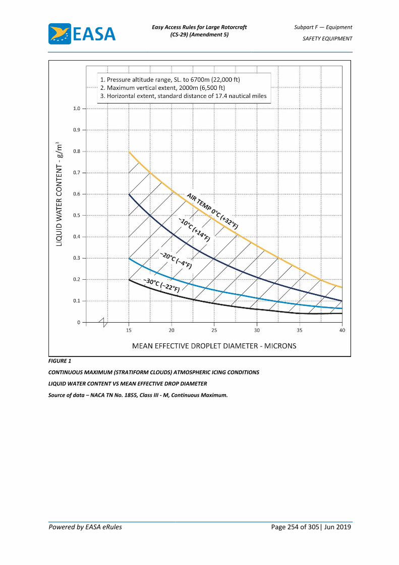
Easy Access Rules for Large Rotorcraft (CS-29) (Amendment 5)
Subpart F — Equipment
SAFETY EQUIPMENT
Powered by EASA eRules Page 254 of 305| Jun 2019
FIGURE 1
CONTINUOUS MAXIMUM (STRATIFORM CLOUDS) ATMOSPHERIC ICING CONDITIONS
LIQUID WATER CONTENT VS MEAN EFFECTIVE DROP DIAMETER
Source of data – NACA TN No. 1855, Class III - M, Continuous Maximum.

Easy Access Rules for Large Rotorcraft (CS-29) (Amendment 5)
Subpart F — Equipment
SAFETY EQUIPMENT
Powered by EASA eRules Page 255 of 305| Jun 2019
FIGURE 2
CONTINUOUS MAXIMUM (STRATIFORM CLOUDS) ATMOSPHERIC ICING CONDITIONS
AMBIENT TEMPERATURE VS PRESSURE ALTITUDE
Source of data – NACA TN No. 2569.
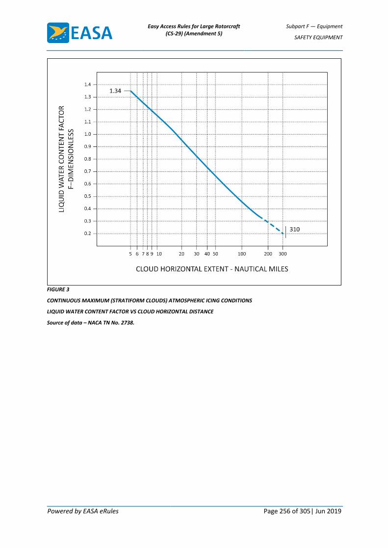
Easy Access Rules for Large Rotorcraft (CS-29) (Amendment 5)
Subpart F — Equipment
SAFETY EQUIPMENT
Powered by EASA eRules Page 256 of 305| Jun 2019
FIGURE 3
CONTINUOUS MAXIMUM (STRATIFORM CLOUDS) ATMOSPHERIC ICING CONDITIONS
LIQUID WATER CONTENT FACTOR VS CLOUD HORIZONTAL DISTANCE
Source of data – NACA TN No. 2738.

Easy Access Rules for Large Rotorcraft (CS-29) (Amendment 5)
Subpart F — Equipment
SAFETY EQUIPMENT
Powered by EASA eRules Page 257 of 305| Jun 2019
FIGURE 4
INTERMITTENT MAXIMUM (CUMULIFORM CLOUDS) ATMOSPHERIC ICING CONDITIONS
LIQUID WATER CONTENT VS MEAN EFFECTIVE DROP DIAMETER
Source of data – NACA TN No. 1855, Class II - M, Intermittent Maximum.

Easy Access Rules for Large Rotorcraft (CS-29) (Amendment 5)
Subpart F — Equipment
SAFETY EQUIPMENT
Powered by EASA eRules Page 258 of 305| Jun 2019
FIGURE 5
INTERMITTENT MAXIMUM (CUMULIFORM CLOUDS) ATMOSPHERIC ICING CONDITIONS
AMBIENT TEMPERATURE VS PRESSURE ALTITUDE
Source of data – NACA TN No. 2569.

Easy Access Rules for Large Rotorcraft (CS-29) (Amendment 5)
Subpart F — Equipment
SAFETY EQUIPMENT
Powered by EASA eRules Page 259 of 305| Jun 2019
FIGURE 6
INTERMITTENT MAXIMUM (CUMULIFORM CLOUDS) ATMOSPHERIC ICING CONDITIONS
VARIATION OF LIQUID WATER CONTENT FACTOR WITH CLOUD HORIZONTAL EXTENT
Source of data – NACA TN No. 2738.
Easy Access Rules for Large Rotorcraft (CS-29) (Amendment 5)
Subpart F — Equipment
MISCELLANEOUS EQUIPMENT
Powered by EASA eRules Page 260 of 305| Jun 2019
MISCELLANEOUS EQUIPMENT
CS 29.1431 Electronic equipment ED Decision 2003/16/RM
(a) Radio communication and navigation installations must be free from hazards in themselves, in their method of operation, and in their effects on other components, under any critical environmental conditions.
(b) Radio communication and navigation equipment, controls, and wiring must be installed so that operation of any one unit or system of units will not adversely affect the simultaneous operation of any other radio or electronic unit, or system of units, required by any applicable CS or operating rule.
CS 29.1433 Vacuum systems ED Decision 2003/16/RM
(a) There must be means, in addition to the normal pressure relief, to automatically relieve the pressure in the discharge lines from the vacuum air pump when the delivery temperature of the air becomes unsafe.
(b) Each vacuum air system line and fitting on the discharge side of the pump that might contain flammable vapours or fluids must meet the requirements of CS 29.1183 if they are in a designated fire zone.
(c) Other vacuum air system components in designated fire zones must be at least fire resistant.
CS 29.1435 Hydraulic systems ED Decision 2003/16/RM
(a) Design. Each hydraulic system must be designed as follows:
(1) Each element of the hydraulic system must be designed to withstand, without detrimental, permanent deformation, any structural loads that may be imposed simultaneously with the maximum operating hydraulic loads.
(2) Each element of the hydraulic system must be designed to withstand pressures sufficiently greater than those prescribed in sub-paragraph (b) to show that the system will not rupture under service conditions.
(3) There must be means to indicate the pressure in each main hydraulic power system.
(4) There must be means to ensure that no pressure in any part of the system will exceed a safe limit above the maximum operating pressure of the system, and to prevent excessive pressures resulting from any fluid volumetric change in lines likely to remain closed long enough for such a change to take place. The possibility of detrimental transient (surge) pressures during operation must be considered.
(5) Each hydraulic line, fitting, and component must be installed and supported to prevent excessive vibration and to withstand inertia loads. Each element of the installation must be protected from abrasion, corrosion, and mechanical damage.
(6) Means for providing flexibility must be used to connect points, in a hydraulic fluid line, between which relative motion or differential vibration exists.

Easy Access Rules for Large Rotorcraft (CS-29) (Amendment 5)
Subpart F — Equipment
MISCELLANEOUS EQUIPMENT
Powered by EASA eRules Page 261 of 305| Jun 2019
(b) Tests. Each element of the system must be tested to a proof pressure of 1.5 times the maximum pressure to which that element will be subjected in normal operation, without failure, malfunction, or detrimental deformation of any part of the system.
(c) Fire protection. Each hydraulic system using flammable hydraulic fluid must meet the applicable requirements of CS 29.861, 29.1183, 29.1185, and 29.1189.
CS 29.1439 Protective breathing equipment ED Decision 2003/16/RM
(a) If one or more cargo or baggage compartments are to be accessible in flight, protective breathing equipment must be available for an appropriate crew member.
(b) For protective breathing equipment required by sub-paragraph (a) or by any applicable operating rule:
(1) That equipment must be designed to protect the crew from smoke, carbon dioxide, and other harmful gases while on flight deck duty;
(2) That equipment must include:
(i) Masks covering the eyes, nose, and mouth; or
(ii) Masks covering the nose and mouth, plus accessory equipment to protect the eyes; and
(3) That equipment must supply protective oxygen of 10 minutes duration per crew member at a pressure altitude of 2438 m (8000 ft) with a respiratory minute volume of 30 litres per minute BTPD.
CS 29.1457 Cockpit voice recorders ED Decision 2003/16/RM
(a) Each cockpit voice recorder required by the applicable operating rules must be approved, and must be installed so that it will record the following:
(1) Voice communications transmitted from or received in the rotorcraft by radio.
(2) Voice communications of flight-crew members on the flight deck.
(3) Voice communications of flight-crew members on the flight deck, using the rotorcraft’s inter-phone system.
(4) Voice or audio signals identifying navigation or approach aids introduced into a headset or speaker.
(5) Voice communications of flight-crew members using the passenger loudspeaker system, if there is such a system, and if the fourth channel is available in accordance with the requirements of sub-paragraph (c)(4)(ii).
(b) The recording requirements of sub-paragraph (a)(2) may be met:
(1) By installing a cockpit-mounted area microphone, located in the best position for recording voice communications originating at the first and second pilot stations and voice communications of other crew members on the flight deck when directed to those stations; or

Easy Access Rules for Large Rotorcraft (CS-29) (Amendment 5)
Subpart F — Equipment
MISCELLANEOUS EQUIPMENT
Powered by EASA eRules Page 262 of 305| Jun 2019
(2) By installing a continually energised or voice-actuated lip microphone at the first and second pilot stations.
The microphone specified in this paragraph must be so located and, if necessary, the preamplifiers and filters of the recorder must be so adjusted or supplemented, that the recorded communications are intelligible when recorded under flight cockpit noise conditions and played back. The level of intelligibility must be approved by the Agency. Repeated aural or visual playback of the record may be used in evaluating intelligibility.
(c) Each cockpit voice recorder must be installed so that the part of the communication or audio signals specified in sub-paragraph (a) obtained from each of the following sources is recorded on a separate channel:
(1) For the first channel, from each microphone, headset, or speaker used at the first pilot station.
(2) For the second channel, from each microphone, headset, or speaker used at the second pilot station.
(3) For the third channel, from the cockpit-mounted area microphone, or the continually energised or voice-actuated lip microphones at the first and second pilot stations.
(4) For the fourth channel, from:
(i) Each microphone, headset, or speaker used at the stations for the third and fourth crew members; or
(ii) If the stations specified in sub-paragraph (c)(4)(i) are not required or if the signal at such a station is picked up by another channel, each microphone on the flight deck that is used with the passenger loudspeaker system if its signals are not picked up by another channel.
(iii) Each microphone on the flight deck that is used with the rotorcraft’s loudspeaker system if its signals are not picked up by another channel.
(d) Each cockpit voice recorder must be installed so that:
(1) It receives its electric power from the bus that provides the maximum reliability for operation of the cockpit voice recorder without jeopardising service to essential or emergency loads:
(2) There is an automatic means to simultaneously stop the recorder and prevent each erasure feature from functioning, within 10 minutes after crash impact; and
(3) There is an aural or visual means for pre-flight checking of the recorder for proper operation.
(e) The record container must be located and mounted to minimise the probability of rupture of the container as a result of crash impact and consequent heat damage to the record from fire.
(f) If the cockpit voice recorder has a bulk erasure device, the installation must be designed to minimise the probability of inadvertent operation and actuation of the device during crash impact.
(g) Each recorder container must be either bright orange or bright yellow.

Easy Access Rules for Large Rotorcraft (CS-29) (Amendment 5)
Subpart F — Equipment
MISCELLANEOUS EQUIPMENT
Powered by EASA eRules Page 263 of 305| Jun 2019
CS 29.1459 Flight recorder ED Decision 2003/16/RM
(a) Each flight recorder required by the applicable operating rules must be installed so that:
(1) It is supplied with airspeed, altitude, and directional data obtained from sources that meet the accuracy requirements of CS 29.1323, 29.1325, and 29.1327, as applicable;
(2) The vertical acceleration sensor is rigidly attached, and located longitudinally within the approved centre of gravity limits of the rotorcraft;
(3) It receives its electrical power from the bus that provides the maximum reliability for operation of the flight recorder without jeopardising service to essential or emergency loads;
(4) There is an aural or visual means for pre-flight checking of the recorder for proper recording of data in the storage medium; and
(5) Except for recorders powered solely by the engine-driven electrical generator system, there is an automatic means to simultaneously stop a recorder that has a data erasure feature and prevent each erasure feature from functioning, within 10 minutes after any crash impact.
(b) Each non-ejectable recorder container must be located and mounted so as to minimise the probability of container rupture resulting from crash impact and subsequent damage to the record from fire.
(c) A correlation must be established between the flight recorder readings of airspeed, altitude, and heading and the corresponding readings (taking into account correction factors) of the first pilot’s instruments. This correlation must cover the airspeed range over which the aircraft is to be operated, the range of altitude to which the aircraft is limited, and 360° of heading. Correlation may be established on the ground as appropriate.
(d) Each recorder container must:
(1) Be either bright orange or bright yellow;
(2) Have a reflective tape affixed to its external surface to facilitate its location under water; and
(3) Have an underwater locating device, when required by the applicable operating rules, on or adjacent to the container which is secured in such a manner that it is not likely to be separated during crash impact.
CS 29.1461 Equipment containing high energy rotors ED Decision 2003/16/RM
(a) Equipment containing high energy rotors must meet sub-paragraphs (b), (c), or (d).
(b) High energy rotors contained in equipment must be able to withstand damage caused by malfunctions, vibration, abnormal speeds, and abnormal temperatures. In addition:
(1) Auxiliary rotor cases must be able to contain damage caused by the failure of high energy rotor blades; and
(2) Equipment control devices, systems, and instrumentation must reasonably ensure that no operating limitations affecting the integrity of high energy rotors will be exceeded in service.
Easy Access Rules for Large Rotorcraft (CS-29) (Amendment 5)
Subpart F — Equipment
MISCELLANEOUS EQUIPMENT
Powered by EASA eRules Page 264 of 305| Jun 2019
(c) It must be shown by test that equipment containing high energy rotors can contain any failure of a high energy rotor that occurs at the highest speed obtainable with the normal speed control devices inoperative.
(d) Equipment containing high energy rotors must be located where rotor failure will neither endanger the occupants nor adversely affect continued safe flight.
CS 29.1465 Vibration Health Monitoring ED Decision 2012/022/R
(a) If certification of a rotorcraft with vibration health monitoring of the rotors and/or rotor drive systems is requested by the applicant, then the design and performance of an installed system must provide a reliable means of early detection for the identified failure modes being monitored.
(b) If a vibration health monitoring system of the rotors and/or rotor drive systems is required by the applicable operating rules, then the design and performance of the vibration health monitoring system must, in addition, meet the requirements of this paragraph.
(1) A safety analysis must be used to identify all component failure modes that could prevent continued safe flight or safe landing, for which vibration health monitoring could provide a reliable means of early detection;
(2) All typical VHM indicators and signal processing techniques should be considered in the VHM System design;
(3) Vibration health monitoring must be provided as identified in subparagraph (1) and (2), unless other means of health monitoring can be substantiated.
[Amdt 29/3]
AMC 29.1465 Vibration health monitoring ED Decision 2012/022/R
a. Explanation
(1) The purpose of this AMC is to provide an Acceptable Means of Compliance and Guidance Material for the design and certification of Vibration Health Monitoring (VHM) applications. VHM is used to increase the likelihood of detection of dynamic component incipient faults in the rotors and rotor drive systems that could prevent continued safe flight or safe landing, by providing timely indications of potential failures to maintenance personnel.
(2) Designing a VHM system in accordance with this AMC is expected to achieve the required performance together with acceptable levels of system integrity and reliability for compliance with type certification and/or operational regulations that require VHM of rotor and/or rotor drive systems.
(3) This AMC defines terms, processes, performance and standards that a VHM system should meet and also the support that a VHM approval holder should provide after the system has entered into service.
(4) VHM systems which satisfy this AMC and that perform functions, the failure of which are categorised as Minor or No Safety Effect (see paragraph p.), can be accepted without the need for additional compliance with AC 29-2C MG15.

Easy Access Rules for Large Rotorcraft (CS-29) (Amendment 5)
Subpart F — Equipment
MISCELLANEOUS EQUIPMENT
Powered by EASA eRules Page 265 of 305| Jun 2019
Note 1: FAA AC 29-2C Miscellaneous Guidance (MG)15, which addresses the use of HUMS in Maintenance, is complementary to this AMC.
Note 2: If an applicant wishes to install a VHM system that is not compliant with CS 29.1465(a), it may still be accepted for installation on a “No hazard/No credit” basis. However, it cannot replace any existing type-design maintenance instructions or change the established methods of complying with CS-29.
b. Procedures
(1) CS 29.1465 does not mandate the fitment of VHM systems. However, if a VHM system is installed on the rotorcraft to meet a type-certification or operational rule, then compliance is required. Three typical scenarios are foreseen as to when compliance by the applicant may be requested. The three scenarios in question are:
(i) as a means of demonstrating compliance with an operational rule requiring helicopters be fitted with a VHM system and that operators of such helicopters implement procedures covering data collection, analysis and determination of serviceability;
(ii) as a selected compensating provision to mitigate the probability of a failure condition, identified from the design assessments of CS 29.547(b) and/or CS 29.917(b), from arising;
(iii) on a voluntary basis to meet a customer requirement or company objective.
(2) CS 29.1465(a) allows non-required and/or partial VHM applications with limited capability to monitor specific failure modes to be approved. Such systems can offer safety benefits and it is not the intention here to discourage their installation and use. However, any installed system must meet CS 29.1301 and be of a kind and design appropriate to its intended function and function properly when installed. The guidance given in this AMC is therefore considered to be applicable to these types of VHM systems.
(3) Where an operating rule mandates installation of a VHM system, CS 29.1465(b) aims to provide a VHM system capability that maximises the safety benefit. All typical VHM indicators and signal processing techniques should be considered in the VHM design and a system safety assessment undertaken to identify failure modes where VHM could provide early detection of incipient failures. VHM must be provided for all potential failure modes unless other means of health monitoring can be substantiated.
(4) The safety analysis required by CS 29.1465(b)(1) is limited to rotors and rotor drive systems. The existing design assessments of CS 29.547 and CS 29.917 can be used for this purpose. All component failure modes that could prevent continued safe flight or safe landing (Catastrophic and Hazardous failure conditions) and for which vibration health monitoring could provide a reliable means of early detection must be identified. Previous experience together with the guidance in this AMC can be used to determine failure modes that could benefit from VHM and the applicable techniques that can produce reliable indications of incipient failures.
(5) CS 29.1465(b)(2) requires the design and performance of the VHM system to consider indicators and processing techniques used on typical existing VHM installations. A non-exhaustive list is provided in Table 1 of this AMC.
(6) CS 29.1465(b)(3) states that VHM must be provided as identified in subparagraph (b)(1) and (b)(2), unless other means of health monitoring can be substantiated. For many failure modes, there may be other compensating provisions which are capable of

Easy Access Rules for Large Rotorcraft (CS-29) (Amendment 5)
Subpart F — Equipment
MISCELLANEOUS EQUIPMENT
Powered by EASA eRules Page 266 of 305| Jun 2019
providing protection against the risk of premature failure. In such cases, the added benefit of VHM in increasing the likelihood of early detection should be assessed. It will not be necessary to implement VHM for a given failure mode if no safety benefit can be established.
c. Definitions
(1) Alarm: An Alert that, following additional processing or investigation, has resulted in a maintenance action being required.
(2) Alert: An indication produced by the VHM system that requires further processing or investigation by the operator to determine if corrective maintenance action is required.
(3) Commercial Off-the-Shelf (COTS): This term defines equipment hardware and software that is not qualified to aircraft standards.
(4) Controlled Service Introduction (CSI): A period in-service where capabilities and functions that could not be verified prior to entry into service (including support functions) are evaluated.
(5) False Alarm: An Alert that after further processing or investigation has resulted in unnecessary maintenance action.
(6) False Alert: This is an Alert that after further processing or investigation has been determined to not require any further action.
(7) Ground-Based System: A means of access to VHM data, including Alerts, for immediate post-flight fault diagnosis by the responsible maintenance staff.
(8) Prognostic Interval: The predicted time between an Alarm and the component becoming unairworthy.
(9) Vibration Health Monitoring (VHM): Use of data generated by processing vibration signals to detect incipient failure or degradation of mechanical integrity.
(10) VHM Application: A VHM function implemented for a defined purpose.
(11) VHM Indicator: A VHM Indicator is the result of processing sampled data by applying an algorithm to achieve a single value, which relates to the health of a component with respect to a particular failure mode.
(12) VHM System: Typically comprises vibration sensors and associated wiring, data acquisition and processing hardware, the means of downloading data from the rotorcraft, the Ground-Based System and all associated instructions for operation of the system.
d. Component Monitoring Capability
The scope of the VHM capability is determined by the range of components monitored and their incipient failures which can be detected. For each component to be monitored the range of potential damage being diagnosed should be declared and the principles of the monitoring techniques applied should be described. The health monitoring effectiveness should be demonstrable (see paragraph o).
e. System Design Considerations
(1) Sensors: They are the hardware that measures vibration. They should provide a reliable signal with an appropriate and defined performance. The position and installation of a vibration sensor is as critical as its performance. Sensor selection, positioning and installation should be designed to enable analysis of the processed signals to discriminate the vibration characteristics of the declared monitored component failure modes. Built-

Easy Access Rules for Large Rotorcraft (CS-29) (Amendment 5)
Subpart F — Equipment
MISCELLANEOUS EQUIPMENT
Powered by EASA eRules Page 267 of 305| Jun 2019
In Test capability is necessary to determine the correct functioning of the sensor. Maintenance instructions should ensure that the correct function, and any calibration, of sensors and their installation are adequately controlled.
(2) Signal Acquisition: It is likely that processed VHM data will be sensitive to the flight regime of the rotorcraft. For this reason it is desirable to focus data acquisition to particular operating conditions or phases of flight. Consideration should be given to the likely operation of rotorcraft that may utilise the VHM system and the practicality of acquiring adequate data from each flight to permit the Alert and Alarm processing to be performed to the required standard. The method of vibration signal acquisition should be designed so that:
(i) The vibration signal sampling rate is sufficient for the required bandwidth and to avoid aliasing with an adequate dynamic range and sensitivity.
(ii) The data acquired from the vibration signal should be automatically gathered in specifically defined regimes at an appropriate rate and quantity for the VHM signal processing to produce robust data for defect detection.
(iii) If the mission profile does not allow regular acquisition of complete data sets, then the data acquisition regimes should be capable of reconfiguration appropriate to particular flight operations.
(iv) The acquisition cycle should be designed in such a way that all selected components and their defects are monitored with an adequate frequency irrespective of any interruptions in the cycle due to the operational profile.
(3) Signal Processing: The helicopter’s rotor and rotor drive systems are a mixture of complex and simple mechanical elements. Therefore, the signal processing or the analysis techniques utilised should reflect the complexity of the mechanical elements being monitored as well as the transmission path of the signal and should be demonstrated as being appropriate to the failure modes to be detected. The objective of processing the sampled data should be to produce VHM Indicators that clearly relate to vibration characteristics of the monitored components, from which the health of these components can be determined. A key part of the success of in-service VHM is the signal-to-noise enhancement techniques such as vibration signal averaging for gears and signal band-pass filtering and enveloping for bearings. These techniques are used to generate enhanced component vibration signatures prior to the calculation of the VHM Indicators. Accordingly, the method of signal enhancement should be shown to be effective. The method of signal processing and the analysis techniques utilised to generate the data used for defect detection should be defined for the claimed defect detection capability (see Table 1 below).

Easy Access Rules for Large Rotorcraft (CS-29) (Amendment 5)
Subpart F — Equipment
MISCELLANEOUS EQUIPMENT
Powered by EASA eRules Page 268 of 305| Jun 2019
Table 1: Typical Vibration Health Monitoring Indicators & Signal Processing Techniques
Assembly Component Type Types of VHM indicators used
Engine to main gearbox input drive shafts
Shafts Fundamental shaft order and harmonics
Gearboxes Shafts Fundamental shaft order and harmonics
Gears Gear meshing frequency and harmonics, modulation of meshing waveform, impulse detection and energy measurement, non-mesh-related energy content
Bearings High frequency energy content, impulse detection, signal envelope modulation patterns and energies correlated with bearing defect frequencies
Tail rotor drive shaft Shafts Fundamental shaft order and harmonics
Hangar Bearings As for gearbox bearings, but can utilise simple band-passed signal energy measurements
Oil cooler Oil Cooler Blower and Drive Shaft
Fundamental shaft order and harmonics, blade pass frequency
Main and Tail rotor Rotors Fundamental shaft order and harmonics up to blade pass frequency, plus multiples of this.
Recording and storing of some raw vibration data and the processed vibration signal, from which the Indicators are derived, may also be of significant diagnostic value. Typical signal processing techniques include;
(i) Asynchronous Power Spectrum where phase information or frequency tracking is not required.
(ii) Synchronous Spectrum where phase information or frequency tracking is required.
(iii) Band-pass filtered signal Envelope Power Spectrum Analysis (a recommended technique for gearbox bearings).
(iv) Synchronous Averaging for time and frequency domain signal analysis (a recommended technique for gearbox gears).
(v) Band-pass filtering and the measurement of filtered signal statistics, including crest factor (can be used for bearings not within engines or gearboxes).
(vi) Further signal enhancement techniques are typically required in the calculation of certain VHM indicators targeted at detecting specific defect-related features (e.g. localised signal distortion associated with a gear tooth crack).
Note 1: When showing compliance to CS 29.1465(a), for non-required and/or partial VHM applications with limited capability to monitor specific failure modes, it is not necessary to address the scope of VHM capability stated in Table 1.
Note 2: When showing compliance to CS 29.1465(b), it is not always necessary for the VHM system to cover the complete capability defined in Table 1. However,

Easy Access Rules for Large Rotorcraft (CS-29) (Amendment 5)
Subpart F — Equipment
MISCELLANEOUS EQUIPMENT
Powered by EASA eRules Page 269 of 305| Jun 2019
absence of any of these areas, and/or techniques, should be substantiated. It is acknowledged that the above provides a prescriptive scope for monitoring rotor and rotor drive system components. If alternative methods are proposed, which can be shown to be as effective and reliable as those prescribed and which are to the satisfaction of the Agency, then these can also be accepted.
f. Data Management
The data transfer process from the rotorcraft to the maintenance personnel interface should be sufficient to determine all the VHM Indicators post flight. The upload/download should have minimal impact on flight operations. VHM data should be accessible in order to permit alternative analysis and comparison. The following should be specified:
(1) Data transfer, processing, networking, data integrity assurance.
(2) Methods to ensure the reliability of this process.
(3) The time for upload/download and retrieval of data and/or health report.
(4) Facilities for the warehousing of all of the data downloaded from the VHM systems and to permit timely access to the data.
g. Alert Management
(1) VHM Alert Generation: VHM Alert criteria should be applied to every monitored component. VHM Alerts are produced to indicate possible anomalous behaviour or a specific defect.
Note: The fixed or learnt thresholds for each individual health monitoring indicator may have a limited capability to detect incipient failures in a timely manner. This is because the process for threshold setting is sometimes a compromise between increasing sensitivity and incurring a higher risk of false alarms, or reducing sensitivity, which will delay the point at which a rising indicator value will trigger an alert. In-service experience has shown that MGB component fatigue failures can propagate from initiation to failure in a relatively short period of time, thus the use of fixed thresholds alone may not provide a timely indication of impending failure. One characteristic that can often provide an earlier indication of anomalous behaviour is the rate of change of a health monitoring indicator, and automatic trend detection software has been developed and shown to be effective. Another method, commonly referred to as Advanced Anomaly Detection (AAD), combines numerous indicators into multi-dimensional parameters, whereby simultaneous changes of multiple indicators can provide increased confidence of the anomalous behaviour at an earlier point in the failure process. (Further information on AAD can be found in Related documents v.(3)).
(2) VHM Alert Management: Diagnostic processes are required to determine if VHM driven maintenance of the rotorcraft is necessary.
h. Pilot Interface
Pilot interaction with the VHM system, if any, should be specified and should not adversely impact on pilot workload.
Note: The level of system integrity for VHM provided under this AMC is not sufficient to support the provision of in-flight cockpit VHM alerts.

Easy Access Rules for Large Rotorcraft (CS-29) (Amendment 5)
Subpart F — Equipment
MISCELLANEOUS EQUIPMENT
Powered by EASA eRules Page 270 of 305| Jun 2019
i. Maintenance Personnel Interface
The person responsible for releasing a rotorcraft into service should be provided with VHM data, maintenance recommendations and VHM system Built-In Test data necessary to release that rotorcraft. This should include the ability to view VHM Indicators, trend data and detection criteria, including thresholds, for relevant VHM parameters from that rotorcraft. These capabilities should be available locally to maintenance personnel for immediate post flight fault diagnosis.
j. Fleet Diagnostic Support Interface
Where an operator has multiple rotorcraft of the same type, facilities should be made available to the operator to support the analysis of all data acquired by the VHM systems in the operator’s fleet. The operator and all parties supporting the operator should have remote, multi-user and timely access to the data and the diagnostic processes in order to assist in determining the continued airworthiness of their fleet.
k. VHM system installation
The VHM system installation must comply with CS-29, as applicable to the specific rotorcraft type.
l. Ground-Based System Architecture
Any Ground-Based System Architecture requirements should be specified (see paragraph q. Technical Publications). The Ground-Based System may include COTS hardware, software and services, compatible with the Data Management objectives of paragraph (f) above.
m. Software
(1) For the case where the VHM system is stand alone
All software that makes up the VHM processing, whether airborne or ground-based, is to be produced to the software quality standard required to achieve the necessary level of system integrity.
All COTS software should be identified and should be of a quality standard that does not compromise the overall system’s integrity.
All ground-based system software (specifically developed for VHM processing and COTS) should be developed to EUROCAE ED-109A/RTCA DO-278A Assurance Level 5 (AL5). DO 278 Assurance Level 5 (AL5) provides an acceptable method for acceptance of ground-based systems which include COTS.
VHM applications with hazard severity level Major or higher are addressed by MG15 and not AMC 29.1465.
Note: EUROCAE ED-12C/RTCA DO-178C Level D software for airborne systems and EUROCAE ED-109A/RTCA DO-278A Assurance Level 5 for non-airborne systems can be applied where VHM is utilised in addition to traditional helicopter design provisions. This will not require certification to a level any higher than Minor, based on the required reliability for these VHM applications. Should a design be proposed where greater reliance was placed solely on VHM, this would not be in compliance with the “minimise” target of CS 29.917(b) and CS 29.547(b).
(2) For the case where the VHM is integrated into a system with other functions
Software partitioning is addressed in both EUROCAE ED-12C/RTCA DO-178C and EUROCAE ED-109A/RTCA DO-278A.

Easy Access Rules for Large Rotorcraft (CS-29) (Amendment 5)
Subpart F — Equipment
MISCELLANEOUS EQUIPMENT
Powered by EASA eRules Page 271 of 305| Jun 2019
n. Performance Criteria
(1) Signal Acquisition
The applicant for VHM system certification should specify the rate of acquisition of data sets for defect diagnostics in consistent flight regimes.
As a target, the total data set acquired in a flight should be sufficient for complete and reliable diagnostics to be produced for every flight above a defined duration in stabilised conditions. As a minimum, at least the data set for all components should be automatically obtained on each flight of greater than 30 minutes in stabilised conditions without the need for in-flight pilot action. For operations which do not contain periods of stabilised operation of greater than 30 minutes, alternative procedures need to be incorporated to ensure that the total data set is recorded within a specified number of flying hours related to the minimum adequate frequency of data collection determined under AMC 29.1465(e)(2), and in any case no longer than 25 flying hours.
Where subsystem performance is critical or relied upon to achieve the quoted defect probability of detection or False Alert rate, such as sensor accuracy, dynamic range or bandwidth, then this should be quoted.
(2) Data transfer and Storage Capability
The VHM defect status data should be capable of being downloaded during rotors running turnarounds.
All the data sets acquired should be stored until successfully transferred to the Ground-Based System. The storage capacity should not be less than 25 flying hours.
The applicant should describe the maximum interval between data downloads for which the system memory capacity is not exceeded.
In the event that a complete data set is not recorded, the data transfer process should be capable of downloading a partial data set to the Ground-Based System. In such a case, the ground station should alert maintenance personnel of a missing maintenance log or that the data set provided is incomplete.
(3) VHM Alert generation and fault detection performance
The Alert and Alarm generation processing should be designed to achieve a claimed probability of detection that is acceptable to the Agency for each component defect being monitored. Processing to isolate False Alerts and False Alarms should not result in an unacceptable workload. Also this processing should not compromise the verification and validating evidence of claimed defect detection performance. This workload should be assessed prior to completion of the Controlled Service Introduction (CSI) phase.
o. Performance Validation
The applicant should demonstrate how the VHM system provides an acceptable defect detection performance. Experiences gained during the CSI phase should be reviewed to confirm that this is the case.
(1) Validation methodology
It is not practical to verify predicted component defect detection performance for all failure modes by in-service experience or by trials. Therefore it is necessary that the methodology employed can be clearly substantiated from an understanding of how the
Easy Access Rules for Large Rotorcraft (CS-29) (Amendment 5)
Subpart F — Equipment
MISCELLANEOUS EQUIPMENT
Powered by EASA eRules Page 272 of 305| Jun 2019
failure mechanisms affect vibration and how the diagnostic processing will generate appropriate Alarms. Direct or indirect evidence should be provided as follows:
(i) Direct evidence includes:
(A) Actual service experience on VHM equipped rotorcraft of the same or of similar type and configuration, including information from module strips, component removals, inspections and other investigations which is relevant to the review of VHM system performance.
(B) Test rig results.
(C) Rotorcraft trials, investigating cause and effect (for example, introducing degrees of imbalance or mal-alignment and calibrating the techniques response). This should be supported by flight experience to demonstrate that the False Alert criterion can be met and that all the diagnostic indicators lie within reasonable ranges.
Note: A mechanism should be established for requesting maintenance feedback with respect to component failure/degradation and VHM indication. The cases are as follows:
— to verify component condition following rejection after an Alarm, in order to establish the diagnostic accuracy, probability of detection and the False Alarm rate.
— to inform the TC holder in the event that a failure occurs which is monitored by VHM, where the VHM fails to provide an Alarm. This will provide the missed Alarm rate.
(ii) Indirect evidence includes:
(A) Evidence as to the provenance of the technology and its suitability for application to rotorcraft.
(B) Reference to adequate performance in other applications.
(C) Modelling of the processes
The types of evidence stated in (i) and (ii) above can be used to substantiate:
(A) That the Alert processing methodology can deliver an adequate False Alarm rate, Prognostic Interval and probability of detection.
(B) Data acquired in a flight is sufficient for complete and reliable diagnostics to be produced for every flight above a minimum duration in stabilised conditions.
(C) The sensitivity, dynamic range and bandwidth of the signal acquisition are adequate.
(D) That the processed vibration signal-to-noise ratio is acceptable and that it is capable of discriminating the features required to identify potential incipient defects for the monitored components.
Typically, the False Alarm Rate and Alert Management performance will be validated during the CSI phase.
p. VHM System Criticality
(1) It is necessary to understand the criticality of a VHM function in order to determine the appropriate level of integrity required. Criticality describes the severity of the end result

Easy Access Rules for Large Rotorcraft (CS-29) (Amendment 5)
Subpart F — Equipment
MISCELLANEOUS EQUIPMENT
Powered by EASA eRules Page 273 of 305| Jun 2019
of a VHM application failure/malfunction and is determined by an assessment that considers the safety effect that the VHM application can have on the rotorcraft.
Note: The criticality of the VHM function relates only to its contribution to the overall integrity of the component being monitored.
(2) The criticality categories are defined in FAA AC 29.1309. In order to determine the appropriate level of criticality of the VHM function, it will be necessary to perform a safety assessment or functional hazard analysis on the rotorcraft systems affected. This should be carried out in accordance with standard safety assessment requirements such as CS 29.1309. In performing this assessment it will be necessary to consider the possibility of dormant and common mode failures and the possibility of the VHM system introducing additional risks, e.g. due to the False Alarm rate.
(3) Different VHM Systems have functions that can have different levels of criticality, such as those described below:
(i) Many VHM applications provide a method of enhanced health monitoring which adds to traditional techniques that have been used to establish an acceptable level of component integrity. Where a VHM application is not necessary for compliance with CS 29.547(b) and/or CS 29.917(b), the failure effect of these functions is considered to be ‘No Safety Effect’ when there have been no changes to the traditional techniques.
(ii) Where a VHM application is identified as a compensating provision in order to comply with CS 29.547(b) and/or CS 29.917(b), then the failure criticality is considered to be ‘Minor’. A proposed design that places greater reliance on VHM would not be deemed compliant with the “minimise” target of CS 29.547(b) and CS 29.917(b).
(iii) When an on-board VHM system is used to replace existing portable test equipment, and is performing an identical function, (though not necessarily utilising the same method of detection), this can be classified as ‘No Safety Effect’, providing that in such cases there will be no reduction in scheduled component inspection, or extension of overhaul or replacement intervals. A level of system integrity related to Minor criticality supports the reduction or elimination of check flights after standard vibration reduction checks and/or adjustments (rotor track and balance, balancing, absorber tuning, etc.).
As this equipment is airborne equipment, it is considered that a quality standard for the software used is necessary. For this reason software to EUROCAE ED-12C/RTCA DO-178C Level D is necessary.
Note: As there should be no effect on safety of the helicopter as a result of utilising the airborne system, it will not be necessary to carry out recurring independent verification means.
(iv) When a validated on-board VHM system is used to replace an existing maintenance task, this can be considered to be minor if the validated detection capability and integrity is better than the maintenance task being replaced. For example, VHM system monitoring of grease packed bearings which results in modification to manual inspection intervals.
For use of EUROCAE ED-12C/RTCA DO-178C level D software, it will be necessary to carry out periodic functional verification of the VHM system for dormant hardware or software failure or following a hardware or software change. An
Easy Access Rules for Large Rotorcraft (CS-29) (Amendment 5)
Subpart F — Equipment
MISCELLANEOUS EQUIPMENT
Powered by EASA eRules Page 274 of 305| Jun 2019
alternative approach to periodic functional verification is the retention of the original inspection at an increased interval. These instructions will need to be specified in the ICA.
Note: In cases (iii) and (iv), it is essential that the reliability and accuracy of the VHM must be equal to or better than that of the process it is replacing. This will require direct or indirect verification such as seeded fault testing (bench) or operational experience in accordance with paragraph (o) of this AMC. Compliance with paragraph (o) may require access to the design data and MSG3 analysis (or equivalent) used during substantiation of the original maintenance task.
q. Technical Publications
Appropriate Instructions for Continued Airworthiness (ICA) are required by CS 29.1529 and Appendix A. ICA and other supporting data should be available to operators and maintenance organisations before entry into service and should be updated whenever necessary during the service life of the system.
ICA should include the following:
(1) Guidance for the interpretation of the diagnostic information produced by the VHM system for all components monitored, to include Alert and Alarm management, a description of the indicators, and Alert generation methods.
(2) Maintenance instructions defining the actions to be taken in the event of all Alarms, including the appropriate rotorcraft inspections (or other maintenance) necessary for fault-finding to verify the Alarm.
(3) Scheduled maintenance to be carried out on the VHM system itself, including inspections to confirm sensor performance and system functionality.
(4) Instructions for all maintenance of the VHM System, including Illustrated Parts Catalogue/Illustrated Parts Breakdown and wiring diagrams.
(5) Installation instructions for retrofit VHM systems addressing all aspects of VHM system integration with the rotorcraft.
(6) A recommendation of the maximum period of unavailability of VHM functions for inclusion in the rotorcraft Master Minimum Equipment List (MMEL) or maintenance instructions, as required.
(7) Operating Instructions detailing the operation of the VHM system including any ground-based elements or functions.
(8) Required Flight Manual instructions.
r. Training
Suitable training should be made available with respect to operation and maintenance of the VHM system. This training should be made available prior to initial delivery of the VHM system. Training material and training courses should evolve to include lessons learned from service experience and appropriate diagnostic case studies. Training material and training courses should cover:
(1) Installation of the VHM system.
(2) Line maintenance of the VHM system (including VHM system fault-finding, any calibration necessary).

Easy Access Rules for Large Rotorcraft (CS-29) (Amendment 5)
Subpart F — Equipment
MISCELLANEOUS EQUIPMENT
Powered by EASA eRules Page 275 of 305| Jun 2019
(3) Use of the VHM System during Line maintenance to monitor the rotorcraft, including the data transfer, interface with data analysis, response to Alerts and Alarm processing, rotorcraft fault-finding and other Line diagnostic actions.
(4) Necessary system administration functions, covering operational procedures relating to data transfer and storage, recovery from failed down loads and the introduction of hardware and software modifications.
(5) Any data analysis and reporting functions that are expected to be performed by the operator.
s. Product Support — System Data and Diagnostic Support
The necessary support should be provided to operators to ensure that the VHM system remains effective and compliant with any applicable requirements throughout its service life. The support provided should cover both the VHM system itself (i.e. system support), and the data generated (data and diagnostic support).
The data and diagnostic support provided should ensure that:
(1) The operator has timely access to approved external data interpretation and diagnostic advice. It is the responsibility of the approval holder to provide this information; however, this may also involve.
t. Minimum Equipment List (MEL) Recommendation
The MEL should address the Airborne Element of the VHM system. The maximum period for absence of an assessment of any VHM indicator, to which Alert criteria are applied, should be limited to a suitable period and should not exceed 25 hours.
Note: If the VHM data is subject to close monitoring due to an increased likelihood of a developing mechanical problem, the maximum alleviation of 25 hours provided by the MMEL should be reduced or removed.
It is recommended that the VHM system automatically generates an indication to the operator if no VHM data has been gathered for a particular component for longer than a certain number of hours.
In the absence of any VHM data, reversion to the standard procedures used to ensure component integrity should be made.
u. Controlled Service Introduction
(1) When a VHM system initially enters into service or it is adapted to a new application on a different rotorcraft type, then a Controlled Service Introduction (CSI) phase is usually necessary in order to fully validate the system performance.
(2) If a CSI phase is considered to be necessary, then this activity should be detailed in a CSI plan to be approved prior to release to service, detailing the VHM applications being developed and the criteria for the successful completion of the CSI. Such criteria should address:
(i) The number of rotorcraft, number of operators, calendar time and flying hours.
(ii) Validation of specific sensor performance.
(iii) If targeted failures or defects occur during the CSI phase, it should be verified that the applicable VHM system applications provide an accurate timely Alarm. (iv) Validate the False Alarm rate.

Easy Access Rules for Large Rotorcraft (CS-29) (Amendment 5)
Subpart F — Equipment
MISCELLANEOUS EQUIPMENT
Powered by EASA eRules Page 276 of 305| Jun 2019
(v) Evolution of Alert criteria.
(vi) Validate the timeliness and integrity of the end-to-end data transfer and analysis process.
(vii) Demonstration of specific support processes.
(viii) System hardware reliability.
(ix) System maintainability.
(x) System usability (including rotorcraft and ground based man-machine interfaces).
(xi) ICA usability.
(xii) Effectiveness of training.
(xiii) Effectiveness and timeliness of diagnostic support.
(3) A CSI Plan should be agreed between the applicant for VHM system certification and the Agency prior to initial approval of the VHM system. This plan should then be implemented by the VHM approval holder and the operator(s) and monitored periodically by the Agency. Prior to any VHM function replacing an existing maintenance task, it may be necessary to complete a period of in-service operation. The validation and improvement activities should be detailed in this plan which should also detail the objectives that must be achieved before the CSI can be considered to be completed.
(4) Formal CSI meetings should take place in order to review service experience against the CSI criteria. They should involve the VHM system approval holder, the Agency (as applicable), and the operators.
(5) Once all parties agree that the intent of the CSI has been satisfied, the CSI phase will be considered closed. The process of review and closure should be recorded.
v. Related documents
(1) Federal Aviation Administration (FAA) AC 29-2C MG 15 ‘Airworthiness Approval of Rotorcraft Health Usage Monitoring Systems (HUMS)’
http://www.faa.gov/regulations_policies/advisory_circulars/
(2) CAP 753: Helicopter Vibration Health Monitoring (VHM) — Guidance Material for Operators Utilising VHM in Rotor and Rotor Drive Systems of Helicopters
http://www.caa.co.uk/docs/33/CAP753.pdf
(3) CAA Paper 2011/01: Intelligent Management of Helicopter Vibration Health Monitoring Data
http://www.caa.co.uk/docs/33/2011_01RFS.pdf
[Amdt 29/3]
CS 29.1470 Emergency locator transmitter (ELT) ED Decision 2018/007/R
Each emergency locator transmitter, including sensors and antennae, required by the applicable operating rule, must be installed so as to minimise damage that would prevent its functioning following an accident or incident.
[Amdt No: 29/5]

Easy Access Rules for Large Rotorcraft (CS-29) (Amendment 5)
Subpart F — Equipment
MISCELLANEOUS EQUIPMENT
Powered by EASA eRules Page 277 of 305| Jun 2019
AMC 29.1470 Emergency locator transmitters (ELTs) ED Decision 2018/007/R
(a) Explanation
The purpose of this AMC is to provide specific guidance for compliance with CS 29.1301, CS 29.1309, CS 29.1470, CS 29.1529 and CS 29.1581 regarding emergency locator transmitters (ELT) and their installation.
An ELT is considered to be a passive and dormant device whose status is unknown until it is required to perform its intended function. As such, its performance is highly dependent on proper installation and post-installation testing.
(b) References
Further guidance on this subject can be found in the following references:
(1) ETSO-C126b 406 and 121.5 MHZ Emergency Locator Transmitter;
(2) ETSO-C126b 406 MHz Emergency Locator Transmitter;
(3) FAA TSO-C126b 406 MHz Emergency Locator Transmitter (ELT);
(4) EUROCAE ED-62A MOPS for aircraft emergency locator transmitters (406 MHz and 121.5 MHz (optional 243 MHz));
(5) RTCA DO-182 Emergency Locator Transmitter (ELT) Equipment Installation and Performance; and
(6) RTCA DO-204A Minimum Operational Performance Standards for 406 MHz Emergency Locator Transmitters (ELTs).
(c) Definitions
(1) ELT (AF): an ELT (automatic fixed) is intended to be permanently attached to the rotorcraft before and after a crash, is automatically activated by the shock of the crash, and is designed to aid search and rescue (SAR) teams in locating a crash site.
(2) ELT (AP): an ELT (automatic portable) is intended to be rigidly attached to the rotorcraft before a crash and is automatically activated by the shock of the crash, but is readily removable from the rotorcraft after a crash. It functions as an ELT (AF) during the crash sequence. If the ELT does not employ an integral antenna, the rotorcraft-mounted antenna may be disconnected and an auxiliary antenna (stowed in the ELT case) connected in its place. The ELT can be tethered to a survivor or a life raft. This type of ELT is intended to assist SAR teams in locating the crash site or survivor(s).
(3) ELT (S): an ELT (survival) should survive the crash forces, be capable of transmitting a signal, and have an aural or visual indication (or both) that power is on. Activation of an ELT (S) usually occurs by manual means but automatic activation (e.g. activation by water) may also apply.
(i) ELT (S) Class A (buoyant): this type of ELT is intended to be removed from the rotorcraft, deployed and activated by survivors of a crash. It can be tethered to a life raft or a survivor. The equipment should be buoyant and it should be designed to operate when floating in fresh or salt water, and should be self-righting to establish the antenna in its nominal position in calm conditions.
(ii) ELT (S) Class B (non-buoyant): this type of ELT should be integral to a buoyant device in the rotorcraft, deployed and activated by the survivors of a crash.

Easy Access Rules for Large Rotorcraft (CS-29) (Amendment 5)
Subpart F — Equipment
MISCELLANEOUS EQUIPMENT
Powered by EASA eRules Page 278 of 305| Jun 2019
(4) ELT (AD) or automatically deployable emergency locator transmitter (ADELT): this type of automatically deployable ELT is intended to be rigidly attached to the rotorcraft before a crash and automatically deployed after the crash sensor determines that a crash has occurred or after activation by a hydrostatic sensor. This type of ELT should float in water and is intended to aid SAR teams in locating the crash site.
(5) A crash acceleration sensor (CAS) is a device that detects an acceleration and initiates the transmission of emergency signals when the acceleration exceeds a predefined threshold (Gth). It is also often referred to as a ‘g switch’.
(d) Procedures
(1) Installation aspects of ELTs
The installation of the equipment should be designed in accordance with the ELT manufacturer’s instructions.
(i) Installation of the ELT transmitter unit and crash acceleration sensors
The location of the ELT should be chosen to minimise the potential for inadvertent activation or damage by impact, fire, or contact with passengers, baggage or cargo.
The ELT transmitter unit should ideally be mounted on primary rotorcraft load-carrying structures such as trusses, bulkheads, longerons, spars, or floor beams (not rotorcraft skin). Alternatively, the structure should meet the requirements of the test specified in 6.1.8 of ED-62A. For convenience, the requirements of this test are reproduced here, as follows:
‘The mounts shall have a maximum static local deflection no greater than 2.5 mm when a force of 450 Newtons (100 lbf) is applied to the mount in the most flexible direction. Deflection measurements shall be made with reference to another part of the airframe not less than 0.3 m or more than 1.0 m from the mounting location.’
However, this does not apply to an ELT (S), which should be installed or stowed in a location that is conspicuously marked and readily accessible, or should be integral to a buoyant device such as a life raft, depending on whether it is of Class A or B.
A poorly designed crash acceleration sensor installation can be a source of problems such as nuisance triggers, failures to trigger and failures to deploy.
Nuisance triggers can occur when the crash acceleration sensor does not work as expected or is installed in a way that exposes it to shocks or vibration levels outside those assumed during equipment qualification. This can also occur as a result of improper handling and installation practices.
A failure to trigger can occur when an operational ELT is installed such that the crash sensor is prevented from sensing the relevant crash accelerations.
Particular attention should be paid to the installation orientation of the crash acceleration sensor. If the equipment contains a crash sensor with particular installation orientation needs, the part of the equipment containing the crash sensor will be clearly marked by the ELT manufacturer to indicate the correct installation orientation(s).
The design of the installation should follow the instructions contained in the installation manual provided by the equipment manufacturer. In the absence of an installation manual, in general, in the case of a helicopter installation, if the equipment has been designed to be installed on fixed-wing aircraft, it may
Easy Access Rules for Large Rotorcraft (CS-29) (Amendment 5)
Subpart F — Equipment
MISCELLANEOUS EQUIPMENT
Powered by EASA eRules Page 279 of 305| Jun 2019
nevertheless be acceptable for a rotorcraft application. In such cases, guidance should be sought from the equipment manufacturer. This has typically resulted in a recommendation to install the ELT with a different orientation, e.g. of 45 degrees with respect to the main longitudinal axis (versus zero degrees for a fixed wing application). This may help the sensor to detect forces in directions other than the main longitudinal axis, since, during a helicopter crash, the direction of the impact may differ appreciably from the main aircraft axis. However, some ELTs are designed specifically for helicopters or designed to sense forces in several axes.
(ii) Use of hook and loop style fasteners
In several recent aircraft accidents, ELTs mounted with hook and loop style fasteners, commonly known by the brand name Velcro®, have detached from their aircraft mountings. The separation of the ELT from its mount could cause the antenna connection to be severed, rendering the ELT ineffective.
Inconsistent installation and reinstallation practices can lead to the hook and loop style fastener not having the necessary strength to perform its intended function. Furthermore, the retention capability of the hook and loop style fastener may degrade over time, due to wear and environmental factors such as vibration, temperature, or contamination. The safety concern about these attachments increases when the ELT manufacturer’s instructions for continued airworthiness (ICA) do not contain specific instructions for regularly inspecting the hook and loop style fasteners, or a replacement interval (e.g. Velcro life limit). This concern applies, regardless of how the hook and loop style fastener is installed in the aircraft.
Separation of ELTs has occurred, even though the associated hook and loop style fastener design was tested during initial European Technical Standard Order (ETSO) compliance verification against crash shock requirements.
Therefore, it is recommended that when designing an ELT installation, the ELT manufacturer’s ICA is reviewed and it is ensured that the ICA for the rotorcraft (or the modification, as applicable) appropriately addresses the in-service handling of hook and loop style fasteners.
It is to be noted that ETSO/TSO-C126b states that the use of hook and loop fasteners is not an acceptable means of attachment for automatic fixed (AF) and automatic portable (AP) ELTs.
(iii) ELT antenna installation
This section does not apply to the ELT (S) or ELT (AD) types of ELT.
The most recurrent issue found during accident investigations concerning ELTs is the detachment of the antenna (coaxial cable), causing the transmission of the ELT unit to be completely ineffective.
Chapter 6 of ED-62A addresses the installation of an external antenna and provides guidance, in particular, on:
(A) the location of the antenna;
(B) the position of the antenna relative to the ELT transmission unit;
(C) the characteristics of coaxial-cables; and
(D) the installation of coaxial-cables.

Easy Access Rules for Large Rotorcraft (CS-29) (Amendment 5)
Subpart F — Equipment
MISCELLANEOUS EQUIPMENT
Powered by EASA eRules Page 280 of 305| Jun 2019
Any ELT antenna should be located away from other antennas to avoid disruption of the antenna radiation patterns. In any case, during installation of the antenna, it should be ensured that the antenna has a free line of sight to the orbiting COSPAS-SARSAT satellites at most times when the aircraft is in the normal flight attitude.
Ideally, for the 121.5 MHz ELT antenna, a separation of 2.5 metres from antennas receiving very high frequency (VHF) communications and navigation data is sufficient to minimise unwanted interference. The 406 MHz ELT antenna should be positioned at least 0.8 metres from antennas receiving VHF communications and navigation data to minimise interference.
External antennas which have been shown to be compatible with a particular ELT will either be part of the ETSO/TSO-approved ELT or will be identified in the ELT manufacturer’s installation instructions. Recommended methods for installing antennas are outlined in FAA AC 43.13-2B.
The antenna should be mounted as close to the respective ELT as practicable. Provision should be taken to protect coaxial cables from disconnection or from being cut. Therefore, installation of the external antenna close to the ELT unit is recommended. Coaxial cables connecting the antenna to the ELT unit should not cross rotorcraft production breaks.
In the case of an external antenna installation, ED-62A recommends that its mounting surface should be able to withstand a static load equal to 100 times the antenna’s weight applied at the antenna mounting base along the longitudinal axis of the rotorcraft. This strength can be substantiated by either test or conservative analysis.
If the antenna is installed within a fin cap, the fin cap should be made of an RF-transparent material that will not severely attenuate the radiated transmission or adversely affect the antenna radiation pattern shape.
In the case of an internal antenna location, the antenna should be installed as close to the ELT unit as practicable, insulated from metal window casings and restrained from movement within the cabin area. The antenna should be located such that its vertical extension is exposed to an RF-transparent window. The antenna’s proximity to the vertical sides of the window and to the window pane and casing as well as the minimum acceptable window dimensions should be in accordance with the equipment manufacturer’s instructions.
The voltage standing wave ratio (VSWR) of the installed external antenna should be checked at all working frequencies, according to the test equipment manufacturer’s recommendations, during the first certification exercise for installation on a particular rotorcraft type.
Coaxial cables between the antenna and the ELT unit should be provided on each end with an RF connector that is suitable for the vibration environment of the particular installation application. When the coaxial cable is installed and the connectors mated, each end should have some slack in the cable, and the cable should be secured to rotorcraft structures for support and protection.
In order to withstand exposure to fire or flames, the use of fire-resistant coaxial cables or the use of fire sleeves compliant to SAE AS1072 is recommended.

Easy Access Rules for Large Rotorcraft (CS-29) (Amendment 5)
Subpart F — Equipment
MISCELLANEOUS EQUIPMENT
Powered by EASA eRules Page 281 of 305| Jun 2019
(2) Deployment aspects of ELTs
Automatically deployable emergency locator transmitters (ADELTs) have particularities in their designs and installations that need to be addressed independently of the general recommendations.
The location of an ADELT and its manner of installation should minimise the risk of injury to persons or damage to the rotorcraft in the event of its inadvertent deployment. The means to manually deploy the ADELT should be located in the cockpit, and be guarded, such that the risk of inadvertent manual deployment is minimised.
Automatically deployable ELTs should be located so as to minimise any damage to the structure and surfaces of the rotorcraft during their deployment. The deployment trajectory of the ELT should be demonstrated to be clear of interference from the airframe or any other parts of the rotorcraft, or from the rotor in the case of helicopters. The installation should not compromise the operation of emergency exits or of any other safety features.
In some helicopters, where an ADELT is installed aft of the transport joint in the tail boom, any disruption of the tail rotor drive shaft has the potential to disrupt or disconnect the ADELT wiring. From accident investigations, it can be seen that if a tail boom becomes detached, an ADELT that is installed there, aft of the transport joint, will also become detached before signals from sensors that trigger its deployment can be received.
Therefore, it is recommended to install the ADELT forward of the transport joint of the tail boom. Alternatively, it should be assured that ELT system operation will not be impacted by the detachment of the structural part on which it is installed.
The hydrostatic sensor used for automatic deployment should be installed in a location shown to be immersed in water within a short time following a ditching or water impact, but not subject to water exposure in the expected rotorcraft operations. This assessment should include the most probable rotorcraft attitude when crashed, i.e. its capability to keep an upright position after a ditching or a crash into water.
The installation supporting the deployment feature should be demonstrated to be robust to immersion. Assuming a crash over water or a ditching, water may immerse not only the beacon and the hydrostatic sensor, which is designed for this, but also any electronic component, wires and the source of power used for the deployment.
(3) Additional considerations
(i) Human factors (HF)
The ELT controls should be designed and installed so that they are not activated unintentionally. These considerations should address the control panel locations, which should be clear from normal flight crew movements when getting into and out of the cockpit and when operating the rotorcraft, and the control itself. The means for manually activating the ELT should be guarded in order to avoid unintentional activation.
(ii) The rotorcraft flight manual (RFM) should document the operation of the ELT, and in particular, any feature specific to the installed model.
(iii) Batteries
An ELT operates using its own power source. The ELT manufacturer indicates the useful life and expiration date of the batteries by means of a dedicated label. The

Easy Access Rules for Large Rotorcraft (CS-29) (Amendment 5)
Subpart F — Equipment
MISCELLANEOUS EQUIPMENT
Powered by EASA eRules Page 282 of 305| Jun 2019
installation of the ELT should be such that the label indicating the battery expiration date is clearly visible without requiring the removal of the ELT or other LRU from the rotorcraft.
(4) Maintenance and inspection aspects
This Chapter provides guidance for the applicant to produce ICA related to ELT systems. The guidance is based on Chapter 7 of ED-62A.
(i) The ICA should explicitly mention that:
(A) The self-test function should be performed according to the manufacturer’s recommendation but no less than once every 6 months. Regulation at the place of operation should be considered when performing self-tests, as national aviation authorities (NAAs) may have established specific procedures to perform self-tests.
(B) As a minimum, a periodic inspection should occur at every battery replacement unless an inspection is required more frequently by the airworthiness authorities or the manufacturer.
(ii) Each inspection should include:
(A) the removal of all interconnections to the ELT antenna, and inspection of the cables and terminals;
(B) the removal of the ELT unit, and inspection of the mounting;
(C) access to the battery to check that there is no corrosion;
(D) a check of all the sensors as recommended by Chapter 7.6 of ED-62A — Periodic inspection; and
(E) measurement of the transmission frequencies and the power output.
(5) Rotorcraft flight manual/flight manual supplement (RFM/RFMS)
The rotorcraft flight manual (RFM) or supplement (RFMS), as appropriate, should contain all the pertinent information related to the operation of the ELT, including the use of the remote control panel in the cockpit. If there are any limitations on its use, these should be declared in the ‘Limitations’ section.
Detailed instructions for pre-flight and post-flight checks should be provided. As a pre-flight check, the ELT remote control should be checked to ensure that it is in the armed position. Post-flight, the ELT should be checked to ensure that it does not transmit, by activating the indicator on the remote control or monitoring 121.5 MHz.
Information on the location and deactivation of ELTs should also be provided. Indeed, accident investigations have shown that following aircraft ground impact, the remote control switch on the instrument panel may become inoperative, and extensive fuselage disruption may render the localisation of, and the access to, the ELT unit difficult. As a consequence, in the absence of information available to the accident investigators and first responders, this has led to situations where the ELT transmitted for a long time before being shut down, thus blocking the SAR channel for an extended time period. It is therefore recommended that information explaining how to disarm or shut down the ELT after an accident, including when the remote control switch is inoperative, should be included.
[Amdt No: 29/5]

Easy Access Rules for Large Rotorcraft (CS-29) (Amendment 5)
Subpart G — Operating Limitations and Information
GENERAL
Powered by EASA eRules Page 283 of 305| Jun 2019
SUBPART G — OPERATING LIMITATIONS AND INFORMATION
GENERAL
CS 29.1501 General ED Decision 2016/025/R
(a) Each operating limitation specified in CS 29.1503 to 29.1525 and other limitations and information necessary for safe operation must be established.
(b) The operating limitations and other information necessary for safe operation must be made available to the crew members as prescribed in CS 29.1541 to 29.1593.
[Amdt 29/4]

Easy Access Rules for Large Rotorcraft (CS-29) (Amendment 5)
Subpart G — Operating Limitations and Information
OPERATING LIMITATIONS
Powered by EASA eRules Page 284 of 305| Jun 2019
OPERATING LIMITATIONS
CS 29.1503 Airspeed limitations: general ED Decision 2003/16/RM
(a) An operating speed range must be established.
(b) When airspeed limitations are a function of weight, weight distribution, altitude, rotor speed, power, or other factors, airspeed limitations corresponding with the critical combinations of these factors must be established.
CS 29.1505 Never-exceed speed ED Decision 2003/16/RM
(a) The never-exceed speed, VNE, must be established so that it is:
(1) Not less than 74 km/h (40 knots) (CAS); and
(2) Not more than the lesser of:
(i) 0.9 times the maximum forward speeds established under CS 29.309;
(ii) 0.9 times the maximum speed shown under CS 29.251 and 29.629; or
(iii) 0.9 times the maximum speed substantiated for advancing blade tip mach number effects under critical altitude conditions.
(b) VNE may vary with altitude, rpm, temperature, and weight, if:
(1) No more than two of these variables (or no more than two instruments integrating more than one of these variables) are used at one time; and
(2) The ranges of these variables (or of the indications on instruments integrating more than one of these variables) are large enough to allow an operationally practical and safe variation of VNE.
(c) For helicopters, a stabilised power-off VNE denoted as VNE (power-off) may be established at a speed less than VNE established pursuant to sub-paragraph (a), if the following conditions are met:
(1) VNE (power-off) is not less than a speed midway between the power-on VNE and the speed used in meeting the requirements of:
(i) CS 29.67(a)(3) for Category A helicopters;
(ii) CS 29.65(a) for Category B helicopters, except multi-engine helicopters meeting the requirements of CS 29.67(b); and
(iii) CS 29.67(b) for multi-engine Category B helicopters meeting the requirements of CS 29.67(b).
(2) VNE (power-off) is:
(i) A constant airspeed;
(ii) A constant amount less than power-on VNE; or

Easy Access Rules for Large Rotorcraft (CS-29) (Amendment 5)
Subpart G — Operating Limitations and Information
OPERATING LIMITATIONS
Powered by EASA eRules Page 285 of 305| Jun 2019
(iii) A constant airspeed for a portion of the altitude range for which certification is requested, and a constant amount less than power-on VNE for the remainder of the altitude range.
CS 29.1509 Rotor speed ED Decision 2003/16/RM
(a) Maximum power-off (autorotation). The maximum power-off rotor speed must be established so that it does not exceed 95% of the lesser of:
(1) The maximum design rpm determined under CS 29.309(b); and
(2) The maximum rpm shown during the type tests,
(b) Minimum power-off. The minimum power-off rotor speed must be established so that it is not less than 105% of the greater of:
(1) The minimum shown during the type tests; and
(2) The minimum determined by design substantiation.
(c) Minimum power-on. The minimum power-on rotor speed must be established so that it is:
(1) Not less than the greater of:
(i) The minimum shown during the type tests; and
(ii) The minimum determined by design substantiation; and
(2) Not more than a value determined under CS 29.33(a)(1) and (c)(1).
CS 29.1517 Limiting height-speed envelope ED Decision 2003/16/RM
For Category A rotorcraft, if a range of heights exists at any speed, including zero, within which it is not possible to make a safe landing following power failure, the range of heights and its variation with forward speed must be established, together with any other pertinent information, such as the kind of landing surface.
CS 29.1519 Weight and centre of gravity ED Decision 2003/16/RM
The weight and centre of gravity limitations determined under CS 29.25 and 29.27, respectively, must be established as operating limitations.
CS 29.1521 Powerplant limitations ED Decision 2003/16/RM
(a) General. The powerplant limitations prescribed in this paragraph must be established so that they do not exceed the corresponding limits for which the engines are type certificated.
(b) Take-off operation. The powerplant take- off operation must be limited by:
(1) The maximum rotational speed, which may not be greater than:
(i) The maximum value determined by the rotor design; or
(ii) The maximum value shown during the type tests;
Easy Access Rules for Large Rotorcraft (CS-29) (Amendment 5)
Subpart G — Operating Limitations and Information
OPERATING LIMITATIONS
Powered by EASA eRules Page 286 of 305| Jun 2019
(2) The maximum allowable manifold pressure (for reciprocating engines);
(3) The maximum allowable turbine inlet or turbine outlet gas temperature (for turbine engines);
(4) The maximum allowable power or torque for each engine, considering the power input limitations of the transmission with all engines operating;
(5) The maximum allowable power or torque for each engine considering the power input limitations of the transmission with one engine inoperative;
(6) The time limit for the use of the power corresponding to the limitations established in sub-paragraphs (b)(1) to (5); and
(7) If the time limit established in sub-paragraph (b)(6) exceeds 2 minutes:
(i) The maximum allowable cylinder head or coolant outlet temperature (for reciprocating engines); and
(ii) The maximum allowable engine and transmission oil temperatures.
(c) Continuous operation. The continuous operation must be limited by:
(1) The maximum rotational speed, which may not be greater than:
(i) The maximum value determined by the rotor design; or
(ii) The maximum value shown during the type tests;
(2) The minimum rotational speed shown under the rotor speed requirements in CS 29.1509(c);
(3) The maximum allowable manifold pressure (for reciprocating engines);
(4) The maximum allowable turbine inlet or turbine outlet gas temperature (for turbine engines);
(5) The maximum allowable power or torque for each engine, considering the power input limitations of the transmission with all engines operating;
(6) The maximum allowable power or torque for each engine, considering the power input limitations of the transmission with one engine inoperative; and
(7) The maximum allowable temperatures for –
(i) The cylinder head or coolant outlet (for reciprocating engines);
(ii) The engine oil; and
(iii) The transmission oil.
(d) Fuel grade or designation. The minimum fuel grade (for reciprocating engines) or fuel designation (for turbine engines) must be established so that it is not less than that required for the operation of the engines within the limitations in sub-paragraphs (b) and (c).
(e) Ambient temperature. Ambient temperature limitations (including limitations for winterization installations if applicable) must be established as the maximum ambient atmospheric temperature at which compliance with the cooling provisions of CS 29.1041 to 29.1049 is shown.
(f) Two and one-half minute OEI power operation. Unless otherwise authorised, the use of 2½-minute OEI power must be limited to engine failure operation of multi-engine, turbine powered
Easy Access Rules for Large Rotorcraft (CS-29) (Amendment 5)
Subpart G — Operating Limitations and Information
OPERATING LIMITATIONS
Powered by EASA eRules Page 287 of 305| Jun 2019
rotorcraft for not longer than 2½ minutes for any period in which that power is used. The use of 2½-minute OEI power must also be limited by:
(1) The maximum rotational speed, which may not be greater than:
(i) The maximum value determined by the rotor design; or
(ii) The maximum value shown during the type tests;
(2) The maximum allowable gas temperature;
(3) The maximum allowable torque; and
(4) The maximum allowable oil temperature.
(g) Thirty-minute OEI power operation. Unless otherwise authorised, the use of 30-minute OEI power must be limited to multi-engine, turbine-powered rotorcraft for not longer than 30 minutes after failure of an engine. The use of 30-minute OEI power must also be limited by:
(1) The maximum rotational speed, which may not be greater than:
(i) The maximum value determined by the rotor design; or
(ii) The maximum value shown during the type tests;
(2) The maximum allowable gas temperature;
(3) The maximum allowable torque; and
(4) The maximum allowable oil temperature.
(h) Continuous OEI power operation. Unless otherwise authorised, the use of continuous OEI power must be limited to multi-engine, turbine- powered rotorcraft for continued flight after failure of an engine. The use of continuous OEI power must also be limited by:
(1) The maximum rotational speed, which may not be greater than:
(i) The maximum value determined by the rotor design; or
(ii) The maximum value shown during the type tests.
(2) The maximum allowable gas temperature;
(3) The maximum allowable torque; and
(4) The maximum allowable oil temperature.
(i) Rated 30-second OEI power operation. Rated 30-second OEI power is permitted only on multi-engine, turbine-powered rotorcraft also certificated for the use of rated 2-minute OEI power, and can only be used for continued operation of the remaining engine(s) after a failure or precautionary shutdown of an engine. It must be shown that following application of 30-second OEI power, any damage will be readily detectable by the applicable inspections and other related procedures furnished in accordance with paragraph A29.4 of Appendix A of CS-29. The use of 30-second OEI power must be limited to not more than 30 seconds for any period in which the power is used and by:
(1) The maximum rotational speed which may not be greater than:
(i) The maximum value determined by the rotor design: or
(ii) The maximum value demonstrated during the type tests;
(2) The maximum allowable gas temperature; and
Easy Access Rules for Large Rotorcraft (CS-29) (Amendment 5)
Subpart G — Operating Limitations and Information
OPERATING LIMITATIONS
Powered by EASA eRules Page 288 of 305| Jun 2019
(3) The maximum allowable torque.
(j) Rated 2-minute OEI power operation. Rated 2-minute OEI power is permitted only on multi-engine, turbine-powered rotorcraft, also certificated for the use of rated 30-second OEI power, and can only be used for continued operation of the remaining engine(s) after a failure or precautionary shutdown of an engine. It must be shown that following application of 2-minute OEI power, any damage will be readily detectable by the applicable inspections and other related procedures furnished in accordance with paragraph A29.4 of Appendix A of CS-29. The use of 2-minute OEI power must be limited to not more than 2 minutes for any period in which that power is used, and by:
(1) The maximum rotational speed, which may not be greater than:
(i) The maximum value determined by the rotor designs; or
(ii) The maximum value demonstrated during the type tests;
(2) The maximum allowable gas temperature; and
(3) The maximum allowable torque.
CS 29.1522 Auxiliary power unit limitations ED Decision 2003/16/RM
If an auxiliary power unit that meets the requirements of CS-APU is installed in the rotorcraft, the limitations established for that auxiliary power unit including the categories of operation must be specified as operating limitations for the rotorcraft.
CS 29.1523 Minimum flight crew ED Decision 2003/16/RM
The minimum flight crew must be established so that it is sufficient for safe operation, considering:
(a) The workload on individual crew members;
(b) The accessibility and ease of operation of necessary controls by the appropriate crew member; and
(c) The kinds of operation authorised under CS 29.1525.
CS 29.1525 Kinds of operation ED Decision 2003/16/RM
The kinds of operations (such as VFR, IFR, day, night, or icing) for which the rotorcraft is approved are established by demonstrated compliance with the applicable certification requirements and by the installed equipment.
CS 29.1527 Maximum operating altitude ED Decision 2003/16/RM
The maximum altitude up to which operation is allowed, as limited by flight, structural, powerplant, functional, or equipment characteristics, must be established.

Easy Access Rules for Large Rotorcraft (CS-29) (Amendment 5)
Subpart G — Operating Limitations and Information
OPERATING LIMITATIONS
Powered by EASA eRules Page 289 of 305| Jun 2019
CS 29.1529 Instructions for Continued Airworthiness ED Decision 2003/16/RM
Instructions for continued airworthiness in accordance with Appendix A to CS-29 must be prepared.
Appendix A – Instructions for Continued Airworthiness ED Decision 2012/022/R
A29.1 General
(a) This appendix specifies requirements for the preparation of instructions for continued airworthiness as required by CS 29.1529.
(b) The instructions for continued airworthiness for each rotorcraft must include the instructions for continued airworthiness for each engine and rotor (hereinafter designated ‘products’), for each appliance required by any applicable CS or operating rule, and any required information relating to the interface of those appliances and products with the rotorcraft. If instructions for continued airworthiness are not supplied by the manufacturer of an appliance or product installed in the rotorcraft, the instructions for continued airworthiness for the rotorcraft must include the information essential to the continued airworthiness of the rotorcraft.
A29.2 Format
(a) The instructions for continued airworthiness must be in the form of a manual or manuals as appropriate for the quantity of data to be provided.
(b) The format of the manual or manuals must provide for a practical arrangement.
A29.3 Content
The contents of the manual or manuals must be prepared in a language acceptable to the Agency. The instructions for continued airworthiness must contain the following manuals or sections, as appropriate, and information:
(a) Rotorcraft maintenance manual or section.
(1) Introduction information that includes an explanation of the rotorcraft’s features and data to the extent necessary for maintenance or preventive maintenance.
(2) A description of the rotorcraft and its systems and installations including its engines, rotors, and appliances.
(3) Basic control and operation information describing how the rotorcraft components and systems are controlled and how they operate, including any special procedures and limitations that apply.
(4) Servicing information that covers details regarding servicing points, capacities of tanks, reservoirs, types of fluids to be used, pressures applicable to the various systems, location of access panels for inspection and servicing, locations of lubrication points, the lubricants to be used, equipment required for servicing, tow instructions and limitations, mooring, jacking, and levelling information.
(b) Maintenance Instructions.
(1) Scheduling information for each part of the rotorcraft and its engines, auxiliary power units, rotors, accessories, instruments, and equipment that provides the recommended periods at which they should be cleaned, inspected, adjusted, tested, and lubricated, and the degree of inspection, the applicable wear tolerances, and work recommended at

Easy Access Rules for Large Rotorcraft (CS-29) (Amendment 5)
Subpart G — Operating Limitations and Information
OPERATING LIMITATIONS
Powered by EASA eRules Page 290 of 305| Jun 2019
these periods. However, it is allowed to refer to an accessory, instrument, or equipment manufacturer as the source of this information if it is shown that the item has an exceptionally high degree of complexity requiring specialised maintenance techniques, test equipment, or expertise. The recommended overhaul periods and necessary cross references to the airworthiness limitations section of the manual must also be included. In addition, an inspection program that includes the frequency and extent of the inspections necessary to provide for the continued airworthiness of the rotorcraft must be included.
(2) Trouble-shooting information describing probable malfunctions, how to recognise those malfunctions, and the remedial action for those malfunctions.
(3) Information describing the order and method of removing and replacing products and parts with any necessary precautions to be taken.
(4) Other general procedural instructions including procedures for system testing during ground running, symmetry checks, weighing and determining the centre of gravity, lifting and shoring, and storage limitations.
(c) Diagrams of structural access plates and information needed to gain access for inspections when access plates are not provided.
(d) Details for the application of special inspection techniques including radiographic and ultrasonic testing where such processes are specified.
(e) Information needed to apply protective treatments to the structure after inspection.
(f) All data relative to structural fasteners such as identification, discard recommendations, and torque values.
(g) A list of special tools needed.
A29.4 Airworthiness Limitations Section
The instructions for continued airworthiness must contain a section titled airworthiness limitations that is segregated and clearly distinguishable from the rest of the document. This section must set forth each mandatory replacement time, structural inspection interval, and related structural inspection required for type-certification. If the instructions for continued airworthiness consist of multiple documents, the section required by this paragraph must be included in the principal manual. This section must contain a legible statement in a prominent location that reads – ‘The airworthiness limitations section is approved and variations must also be approved’.
[Amdt 29/2] [Amdt 29/3]

Easy Access Rules for Large Rotorcraft (CS-29) (Amendment 5)
Subpart G — Operating Limitations and Information
MARKINGS AND PLACARDS
Powered by EASA eRules Page 291 of 305| Jun 2019
MARKINGS AND PLACARDS
CS 29.1541 General ED Decision 2003/16/RM
(a) The rotorcraft must contain:
(1) The markings and placards specified in CS 29.1545 to 29.1565; and
(2) Any additional information, instrument markings, and placards required for the safe operation of the rotorcraft if it has unusual design, operating or handling characteristics.
(b) Each marking and placard prescribed in sub-paragraph (a):
(1) Must be displayed in a conspicuous place; and
(2) May not be easily erased, disfigured, or obscured.
CS 29.1543 Instrument markings: general ED Decision 2003/16/RM
For each instrument:
(a) When markings are on the cover glass of the instrument there must be means to maintain the correct alignment of the glass cover with the face of the dial; and
(b) Each arc and line must be wide enough, and located to be clearly visible to the pilot.
CS 29.1545 Airspeed indicator ED Decision 2003/16/RM
(a) Each airspeed indicator must be marked as specified in sub-paragraph (b), with the marks located at the corresponding indicated airspeeds.
(b) The following markings must be made:
(1) A red radial line:
(i) For rotorcraft other than helicopters, at VNE; and
(ii) For helicopters, at VNE (power-on).
(2) A red, cross-hatched radial line at VNE (power-off) for helicopters, if VNE (power- off) is less than VNE (power-on).
(3) For the caution range, a yellow arc.
(4) For the safe operating range, a green arc.
CS 29.1547 Magnetic direction indicator ED Decision 2003/16/RM
(a) A placard meeting the requirements of this paragraph must be installed on or near the magnetic direction indicator.
(b) The placard must show the calibration of the instrument in level flight with the engines operating.

Easy Access Rules for Large Rotorcraft (CS-29) (Amendment 5)
Subpart G — Operating Limitations and Information
MARKINGS AND PLACARDS
Powered by EASA eRules Page 292 of 305| Jun 2019
(c) The placard must state whether the calibration was made with radio receivers on or off.
(d) Each calibration reading must be in terms of magnetic heading in not more than 45° increments.
CS 29.1549 Powerplant instruments ED Decision 2003/16/RM
For each required powerplant instrument, as appropriate to the type of instruments –
(a) Each maximum and, if applicable, minimum safe operating limit must be marked with a red radial or a red line;
(b) Each normal operating range must be marked with a green arc or green line, not extending beyond the maximum and minimum safe limits;
(c) Each take-off and precautionary range must be marked with a yellow arc or yellow line;
(d) Each engine or propeller range that is restricted because of excessive vibration stresses must be marked with red arcs or red lines; and
(e) Each OEI limit or approved operating range must be marked to be clearly differentiated from the markings of sub-paragraphs (a) to (d) except that no marking is normally required for the 30-second OEI limit.
CS 29.1551 Oil quantity indicator ED Decision 2003/16/RM
Each oil quantity indicator must be marked with enough increments to indicate readily and accurately the quantity of oil.
CS 29.1553 Fuel quantity indicator ED Decision 2003/16/RM
If the unusable fuel supply for any tank exceeds 3.8 litres (0.8 Imperial gallon/1 US gallon), or 5% of the tank capacity, whichever is greater, a red arc must be marked on its indicator extending from the calibrated zero reading to the lowest reading obtainable in level flight.
CS 29.1555 Control markings ED Decision 2018/007/R
(a) Each cockpit control, other than primary flight controls or control whose function is obvious, must be plainly marked as to its function and method of operation.
(b) For powerplant fuel controls:
(1) Each fuel tank selector valve control must be marked to indicate the position corresponding to each tank and to each existing cross feed position;
(2) If safe operation requires the use of any tanks in a specific sequence, that sequence must be marked on, or adjacent to, the selector for those tanks; and
(3) Each valve control for any engine of a multi-engine rotorcraft must be marked to indicate the position corresponding to each engine controlled.
(c) Usable fuel capacity must be marked as follows:

Easy Access Rules for Large Rotorcraft (CS-29) (Amendment 5)
Subpart G — Operating Limitations and Information
MARKINGS AND PLACARDS
Powered by EASA eRules Page 293 of 305| Jun 2019
(1) For fuel systems having no selector controls, the usable fuel capacity of the system must be indicated at the fuel quantity indicator.
(2) For fuel systems having selector controls, the usable fuel capacity available at each selector control position must be indicated near the selector control.
(d) For accessory, auxiliary, and emergency controls:
(1) Each essential visual position indicator, such as those showing rotor pitch or landing gear position, must be marked so that each crew member can determine at any time the position of the unit to which it relates; and
(2) Each emergency control must be marked as to method of operation and be red unless it may need to be operated underwater, in which case it must be marked with yellow and black stripes.
(e) For rotorcraft incorporating retractable landing gear, the maximum landing gear operating speed must be displayed in clear view of the pilot.
[Amdt No: 29/5]
AMC 29.1555 Control markings ED Decision 2018/007/R
This AMC supplements FAA AC 29.1555.
(a) Explanation
CS-29 Amendment 5 introduced the need to mark emergency controls for use following a ditching or water impact with black and yellow stripes, instead of red, to make them more conspicuous when viewed underwater.
(b) Procedures
(1) Any emergency control that may be required to be operated underwater (e.g. an emergency flotation system deployment switch, a life raft deployment switch or handle) should be coloured with black and yellow stripes.
(2) Black and yellow markings should consist of at least two bands of each colour of approximately equal widths.
[Amdt No: 29/5]
CS 29.1557 Miscellaneous markings and placards ED Decision 2003/16/RM
(a) Baggage and cargo compartments, and ballast location. Each baggage and cargo compartment, and each ballast location must have a placard stating any limitations on contents, including weight, that are necessary under the loading requirements.
(b) Seats. If the maximum allowable weight to be carried in a seat is less than 77 kg (170 pounds), a placard stating the lesser weight must be permanently attached to the seat structure.
(c) Fuel and oil filler openings. The following apply:
(1) Fuel filler openings must be marked at or near the filler cover with:
(i) The word ‘fuel’;
(ii) For reciprocating engine powered rotorcraft, the minimum fuel grade;

Easy Access Rules for Large Rotorcraft (CS-29) (Amendment 5)
Subpart G — Operating Limitations and Information
MARKINGS AND PLACARDS
Powered by EASA eRules Page 294 of 305| Jun 2019
(iii) For turbine-engine-powered rotorcraft, the permissible fuel designations, except that if impractical, this information may be included in the rotorcraft flight manual, and the fuel filler may be marked with an appropriate reference to the flight manual; and
(iv) For pressure fueling systems, the maximum permissible fueling supply pressure and the maximum permissible defueling pressure.
(2) Oil filler openings must be marked at or near the filler cover with the word ‘oil’.
(d) Emergency exit placards. Each placard and operating control for each emergency exit must differ in colour from the surrounding fuselage surface as prescribed in CS 29.811(f)(2). A placard must be near each emergency exit control and must clearly indicate the location of that exit and its method of operation.
CS 29.1559 Limitations placard ED Decision 2003/16/RM
There must be a placard in clear view of the pilot that specifies the kinds of operations (VFR, IFR, day, night or icing) for which the rotorcraft is approved.
CS 29.1561 Safety equipment ED Decision 2018/007/R
(a) Each safety equipment control to be operated by the crew or passenger in an emergency must be plainly marked with its identification and its method of operation.
(b) Each location, such as a locker or compartment, that carries any fire extinguishing, signalling, or other safety equipment, must be appropriately marked in order to identify the contents and if necessary indicate how to remove the equipment
(c) Each item of safety equipment carried must be marked with its identification and must have obviously marked operating instructions.
[Amdt No: 29/5]
AMC 29.1561 Safety Equipment ED Decision 2018/007/R
This AMC supplements FAA AC 29.1561.
(a) Explanation
CS 29.1561 requires each safety equipment control that can be operated by a crew member or passenger to be plainly marked to identify its function and method of operation. (Note that the marking of safety equipment controls located within the cockpit and intended for use by the flight crew is addressed in CS 29.1555.)
In addition, a location marking for each item of stowed safety equipment should be provided that identifies the contents and how to remove them. All safety equipment, including ditching and survival equipment, should be clearly identifiable and provided with operating instructions. Markings and placards should be conspicuous and durable as per CS 29.1541. Both passengers and crew should be able to easily identify and then use the safety equipment.

Easy Access Rules for Large Rotorcraft (CS-29) (Amendment 5)
Subpart G — Operating Limitations and Information
MARKINGS AND PLACARDS
Powered by EASA eRules Page 295 of 305| Jun 2019
(b) Procedures
(1) Release devices such as levers or latch handles for life rafts and other safety equipment should be plainly marked to identify their function and method of operation. Stencils, permanent decals, placards, or other permanent labels or instructions may be used.
(2) Lockers, compartments, or pouches used to contain safety equipment such as life preservers, etc., should be marked to identify the equipment therein and to also identify, if not obvious, the method or means of accessing or releasing the equipment.
(3) Safety equipment should be labelled and provided with operating instructions for its use or operation.
(4) Locating signs for safety equipment should be legible in daylight from the furthest seated point in the cabin or recognisable from a distance equal to the width of the cabin. Letters, 2.5 cm (1 in) high, should be acceptable to satisfy the recommendation. Operating instructions should be legible from a distance of 76 cm (30 in). These recommendations are based on the exit requirements of CS 29.811(b) and (e)(1).
(5) As prescribed, each life raft and its installed equipment should be provided with clear operating instruction markings that cannot be easily erased or disfigured and are readable at low levels of illumination.
(6) Easily recognised or identified and easily accessible safety equipment located in sight of the occupants, such as a passenger compartment fire extinguisher that all passengers can see, may not require locating signs, stencils, or decals. However, operating instructions are required.
[Amdt No: 29/5]
CS 29.1565 Tail rotor ED Decision 2003/16/RM
Each tail rotor must be marked so that its disc is conspicuous under normal daylight ground conditions.

Easy Access Rules for Large Rotorcraft (CS-29) (Amendment 5)
Subpart G — Operating Limitations and Information
ROTORCRAFT FLIGHT MANUAL
Powered by EASA eRules Page 296 of 305| Jun 2019
ROTORCRAFT FLIGHT MANUAL
CS 29.1581 General ED Decision 2003/16/RM
(a) Furnishing information. A Rotorcraft Flight Manual must be furnished with each rotorcraft, and it must contain the following:
(1) Information required by CS 29.1583 to 29.1589.
(2) Other information that is necessary for safe operation because of design, operating, or handling characteristics.
(b) Approved information. Each part of the manual listed in CS 29.1583 to 29.1589 that is appropriate to the rotorcraft, must be furnished, verified, and approved, and must be segregated, identified, and clearly distinguished from each unapproved part of that manual.
(c) Reserved.
(d) Table of contents. Each Rotorcraft Flight Manual must include a table of contents if the complexity of the manual indicates a need for it.
CS 29.1583 Operating limitations ED Decision 2003/16/RM
(a) Airspeed and rotor limitations. Information necessary for the marking of airspeed and rotor limitations on or near their respective indicators must be furnished. The significance of each limitation and of the colour coding must be explained.
(b) Powerplant limitations. The following information must be furnished:
(1) Limitations required by CS 29.1521.
(2) Explanation of the limitations, when appropriate.
(3) Information necessary for marking the instruments required by CS 29.1549 to 29.1553.
(c) Weight and loading distribution. The weight and centre of gravity limits required by CS 29.25 and CS 29.27, respectively, must be furnished. If the variety of possible loading conditions warrants, instructions must be included to allow ready observance of the limitations.
(d) Flight crew. When a flight crew of more than one is required, the number and functions of the minimum flight crew determined under CS 29.1523 must be furnished.
(e) Kinds of operation. Each kind of operation for which the rotorcraft and its equipment installations are approved must be listed.
(f) Limiting heights. Enough information must be furnished to allow compliance with CS 29.1517.
(g) Maximum allowable wind. For Category A rotorcraft, the maximum allowable wind for safe operation near the ground must be furnished.
(h) Altitude. The altitude established under CS 29.1527 and an explanation of the limiting factors must be furnished.
(i) Ambient temperature. Maximum and minimum ambient temperature limitations must be furnished.
Easy Access Rules for Large Rotorcraft (CS-29) (Amendment 5)
Subpart G — Operating Limitations and Information
ROTORCRAFT FLIGHT MANUAL
Powered by EASA eRules Page 297 of 305| Jun 2019
AMC 29.1583 Operating limitations ED Decision 2016/025/R
This AMC provides further guidance and acceptable means of compliance to supplement FAA AC 29-2C Change 4 (AC 29.1583 § 29.1583 (Amendment 29-24) OPERATING LIMITATIONS), to meet the Agency's interpretation of CS 29.1583. As such it should be used in conjunction with the FAA AC but take precedence over it, where stipulated, in the showing of compliance.
Specifically, this AMC addresses an area where the FAA AC has been deemed by the Agency as being at variance to the Agency’s interpretation. This being as follows:
b. Procedures.
(7) Kinds of operations are established under CS 29.1525. This section should contain the following preamble: ‘This rotorcraft is certified in the Large Category (category B or category A and category B) and is eligible for the following kinds of operations when the appropriate instruments and equipment required by the airworthiness and operating rules are installed and approved and are in an operable condition.’ The following, and any other kinds of operations that are applicable, should be listed.
(i) Day and night VFR.
(ii) Approved to operate in known icing conditions.
(iii) IFR.
(iv) Category A vertical operations from ground level or elevated heliports.
(v) Extended overwater operations (ditching).
(vi) External load operation.
Each operating limitation must be clear, unambiguous, and consistent with any other applicable limitation or regulatory requirement.
[Amdt 29/4]
CS 29.1585 Operating procedures ED Decision 2018/007/R
(a) The parts of the manual containing operating procedures must have information concerning any normal and emergency procedures, and other information necessary for safe operation, including the applicable procedures, such as those involving minimum speeds, to be followed if an engine fails.
(b) For multi-engine rotorcraft, information identifying each operating condition in which the fuel system independence prescribed in CS 29.953 is necessary for safety must be furnished, together with instructions for placing the fuel system in a configuration used to show compliance with that paragraph.
(c) For helicopters for which a VNE (power-off) is established under CS 29.1505(c), information must be furnished to explain the VNE (power-off) and the procedures for reducing airspeed to not more than the VNE (power-off) following failure of all engines.
(d) For each rotorcraft showing compliance with CS 29.1353(c)(6)(ii) or (c)(6)(iii), the operating procedures for disconnecting the battery from its charging source must be furnished.
(e) If the unusable fuel supply in any tank exceeds 5% of the tank capacity, or 3.8 litres (0.8 Imperial gallon/1 US gallon), whichever is greater, information must be furnished which indicates that

Easy Access Rules for Large Rotorcraft (CS-29) (Amendment 5)
Subpart G — Operating Limitations and Information
ROTORCRAFT FLIGHT MANUAL
Powered by EASA eRules Page 298 of 305| Jun 2019
when the fuel quantity indicator reads ‘zero’ in level flight, any fuel remaining in the fuel tank cannot be used safely in flight.
(f) Information on the total quantity of usable fuel for each fuel tank must be furnished.
(g) For Category B rotorcraft, the airspeeds and corresponding rotor speeds for minimum rate of descent and best glide angle as prescribed in CS 29.71 must be provided.
(h) The maximum duration of operation after a failure resulting in a loss of lubrication of a rotor drive system gearbox and an associated oil pressure warning must be furnished and must not exceed the maximum period substantiated in accordance with CS 29.927(c).
[Amdt No: 29/5]
AMC 29.1585 Operating Procedures ED Decision 2018/007/R
CS 29.927(c) provides guidance for the completion of testing to simulate a loss of lubrication and on how to demonstrate confidence in the margin of safety associated with the maximum period of operation following loss of lubrication. This margin of safety is intended to substantiate a period of operation that has been evaluated as likely to be safer than making a forced landing over hostile terrain. Accordingly, the need to ‘Land as Soon as Possible’, which may include ditching where circumstances permit, should be reflected in the associated RFM emergency procedures. This can be supplemented with ’Land Immediately’ in the event of additional conditions to that of low oil pressure being present.
Emergency procedures should identify the need to minimise the power that is used for yaw and accessories following a loss of oil pressure warning.
[Amdt No: 29/5]
CS 29.1587 Performance information ED Decision 2018/007/R
Flight manual performance information which exceeds any operating limitation may be shown only to the extent necessary for presentation clarity or to determine the effects of approved optional equipment or procedures. When data beyond operating limits are shown, the limits must be clearly indicated. The following must be provided:
(a) Category A. For each Category A rotorcraft, the rotorcraft flight manual must contain a summary of the performance data, including data necessary for the application of any applicable operating rule, together with descriptions of the conditions, such as airspeeds, under which this data was determined, and must contain –
(1) The indicated airspeeds corresponding with those determined for take-off and the procedures to be followed if the critical engine fails during take-off;
(2) The airspeed calibrations;
(3) The techniques, associated airspeeds, and rates of descent for autorotative landings;
(4) The rejected take-off distance determined under CS 29.62 and the take-off distance determined under CS 29.61;
(5) The landing data determined under CS 29.81 and 29.85;
Easy Access Rules for Large Rotorcraft (CS-29) (Amendment 5)
Subpart G — Operating Limitations and Information
ROTORCRAFT FLIGHT MANUAL
Powered by EASA eRules Page 299 of 305| Jun 2019
(6) The steady gradient of climb for each weight, altitude, and temperature for which take- off data are to be scheduled, along the take-off path determined in the flight conditions required in CS 29.67(a)(1) and (a)(2):
(i) In the flight conditions required in CS 29.67(a)(1) between the end of the take-off distance and the point at which the rotorcraft is 61 m (200 ft) above the take-off surface (or 61 m (200 ft) above the lowest point of the take-off profile for elevated heliports).
(ii) In the flight conditions required in CS 29.67(a)(2) between the points at which the rotorcraft is 61 m (200 ft) and 305 m (1000 ft) above the take-off surface (or 61 m (200 ft) and 305 m (1000 ft) above the lowest point of the take-off profile for elevated heliports).
(7) Hover performance determined under CS 29.49 and the maximum weight for each altitude and temperature condition at which the rotorcraft can safely hover in-ground effect and out-of-ground effect in winds of not less than 31 km/h (17 knots) from all azimuths. This data must be clearly referenced to the appropriate hover charts.
(b) Category B. For each Category B rotorcraft, the Rotorcraft Flight Manual must contain:
(1) The take-off distance and the climbout speed together with the pertinent information defining the flight path with respect to autorotative landing if an engine fails, including the calculated effects of altitude and temperature;
(2) The steady rates of climb and hovering ceiling, together with the corresponding airspeeds and other pertinent information, including the calculated effects of altitude and temperature;
(3) The landing distance, appropriate airspeed and type of landing surface, together with any pertinent information that might affect this distance, including the effects of weight, altitude and temperature;
(4) The maximum safe wind for operation near the ground;
(5) The airspeed calibrations;
(6) The height-speed envelope except for rotorcraft incorporating this as an operating limitation;
(7) Glide distance as a function of altitude when autorotating at the speeds and conditions for minimum rate of descent and best glide angle, as determined in CS 29.71;
(8) Hover performance determined under CS 29.49 and the maximum safe wind demonstrated under the ambient conditions for data presented. In addition, the maximum weight for each altitude and temperature condition at which the rotorcraft can safely hover in-ground effect and out-of-ground effect in winds of not less than 31 km/h (17 knots) from all azimuths. This data must be clearly referenced to the appropriate hover charts; and
(9) Any additional performance data necessary for the application of any applicable operating rule.
(c) The RFM must contain the substantiated sea conditions and any associated information relating to the certification obtained with ditching or emergency flotation provisions.
[Amdt No: 29/1] [Amdt No: 29/2] [Amdt No: 29/5]

Easy Access Rules for Large Rotorcraft (CS-29) (Amendment 5)
Subpart G — Operating Limitations and Information
ROTORCRAFT FLIGHT MANUAL
Powered by EASA eRules Page 300 of 305| Jun 2019
AMC 29.1587(c) Performance Information ED Decision 2018/007/R
This AMC supplements FAA AC 29.1587, AC 29.1587A and AC 29.1587B.
a. Explanation
The rotorcraft flight manual (RFM) is an important element in the certification process of the rotorcraft for approval with ditching or emergency flotation provisions. The material may be presented in the form of a supplement or a revision to the basic manual. This material should include:
(1) A statement in the ‘Limitations’ section stating that the rotorcraft is approved for ditching or emergency flotation, as appropriate.
If certification with ditching provisions is obtained in a segmented fashion (i.e. one applicant performing the safety equipment installation and operations portion and another designing and substantiating the safety equipment’s performance and deployment facilities), the RFM limitations should state that the ditching provisions are not approved until all the segments are completed. The outstanding ditching provisions for a complete certification should be identified in the ‘Limitations’ section.
(2) Procedures and limitations for the inflation of a flotation device.
(3) A statement in the performance information section of the RFM, identifying the substantiated sea conditions and any other pertinent information. If substantiation was performed using the default North Sea wave climate (JONSWAP), the maximum substantiated significant wave height (Hs) should be stated. If extended testing was performed in accordance with the AMC to 29.801(e) and 29.802(c) to demonstrate that the target level of capsize probability can be reached without any operational limitations, this should also be stated. If substantiation was performed for other sea conditions, the maximum substantiated significant wave height (Hs) and the limits of the geographical area represented should be stated.
(4) Recommended rotorcraft water entry attitude and speed.
(5) Procedures for the use of safety equipment.
(6) Egress and life raft entry procedures.
[Amdt No: 29/5]
CS 29.1589 Loading information ED Decision 2003/16/RM
There must be loading instructions for each possible loading condition between the maximum and minimum weights determined under CS 29.25 that can result in a centre of gravity beyond any extreme prescribed in CS 29.27, assuming any probable occupant weights.
CS 29.1593 Exposure to volcanic cloud hazards ED Decision 2016/025/R
If required by an operating rule, the susceptibility of rotorcraft features to the effects of volcanic cloud hazards must be established.
[Amdt 29/4]
Easy Access Rules for Large Rotorcraft (CS-29) (Amendment 5)
Subpart G — Operating Limitations and Information
ROTORCRAFT FLIGHT MANUAL
Powered by EASA eRules Page 301 of 305| Jun 2019
AMC 29.1593 Exposure to volcanic cloud hazards ED Decision 2016/025/R
The aim of CS 29.1593 is to support commercial and non-commercial operators operating complex motor-powered rotorcraft by identifying and assessing airworthiness hazards associated with operations in contaminated airspace. Providing such data to operators will enable those hazards to be properly managed as part of an established management system.
Acceptable means of establishing the susceptibility of rotorcraft features to the effects of volcanic clouds should include a combination of experience, studies, analysis, and/or testing of parts or sub-assemblies.
Information necessary for safe operation should be contained in the unapproved part of the flight manual or other appropriate manual, and should be readily usable by operators in preparing a safety risk assessment as part of their overall management system.
A volcanic cloud comprises volcanic ash together with gases and other chemicals. Although the primary hazard is volcanic ash itself, other elements of the volcanic cloud may also be undesirable to operate through, thus their effect on airworthiness should be assessed.
In determining the susceptibility of rotorcraft features to the effects of volcanic clouds as well as the necessary information to be provided to operators, the following points should be considered:
(a) Identify the features of the rotorcraft that are susceptible to airworthiness effects of volcanic clouds. These may include but are not limited to the following:
(1) malfunction or failure of one or more engines, leading not only to reduction or complete loss of thrust but also to failures of electrical, pneumatic and hydraulic systems;
(2) blockage of pitot and static sensors, resulting in unreliable airspeed indications and erroneous warnings;
(3) windscreen abrasion, resulting in windscreens rendered partially or completely opaque;
(4) fuel contamination;
(5) volcanic ash and/or toxic chemical contamination of cabin air-conditioning packs, possibly leading to loss of cabin pressurisation or noxious fumes in the cockpit and/or cabin;
(6) erosion, blockage or malfunction of external and internal rotorcraft components;
(7) volcanic cloud static discharge, leading to prolonged loss of communications; and
(8) reduced cooling efficiency of electronic components, leading to a wide range of rotorcraft system failures.
(b) The nature and severity of effects.
(c) Details of any device or system installed on the rotorcraft that can detect the presence of volcanic cloud hazards (e.g. volcanic ash (particulate) sensors or volcanic gas sensors)
(d) The effect of volcanic ash on operations arriving to or departing from contaminated aerodromes.
(e) The related pre-flight, in-flight and post-flight precautions to be taken by the operator including any necessary amendments to Aircraft Operating Manuals, Aircraft Maintenance Manuals, Master Minimum Equipment List/Dispatch Deviation or equivalents, required to support the operator. Pre-flight precautions should include clearly defined procedures for the removal of any volcanic ash detected on parked rotorcraft.

Easy Access Rules for Large Rotorcraft (CS-29) (Amendment 5)
Subpart G — Operating Limitations and Information
ROTORCRAFT FLIGHT MANUAL
Powered by EASA eRules Page 302 of 305| Jun 2019
(f) The recommended continuing-airworthiness inspections associated with operations in airspace contaminated by volcanic cloud(s) and arriving to or departing from aerodromes contaminated by volcanic ash; this may take the form of Instructions for Continued Airworthiness (ICA) or other advice.
[Amdt 29/4]

Easy Access Rules for Large Rotorcraft (CS-29) (Amendment 5)
Miscellaneous guidance
Powered by EASA eRules Page 303 of 305| Jun 2019
MISCELLANEOUS GUIDANCE
MG4 Full Authority Digital Electronic Controls (FADEC) ED Decision 2008/010/R
Note: Certification procedures identified in MG4 refer specifically to the FAA regulatory system. For guidance on EASA procedures, reference should be made to Commission Regulation (EC) No 1702/2003 (as amended) (Part21), AMC20 (and specifically AMC 201 and 203) and to EASA internal working procedures, all of which are available on EASA's web site: http://www.easa.europa.eu/
[Amdt. No. 29/2]
MG5 Agricultural dispensing equipment installation ED Decision 2016/025/R
Certification procedures identified in MG5 refer specifically to the FAA regulatory system and are not fully applicable to the EASA regulatory system due to the different applicability of restricted certification. The EASA regulatory system does not encompass a restricted certification category for design changes or Supplemental Type Certificates.
The certification basis of design changes or Supplemental Type Certificates for agricultural dispensing is to be established in accordance with 21.A.101 of Annex I to Regulation (EU) No 748/2012, on a case-by-case basis through compliance with the applicable airworthiness requirements contained in MG5, supplemented by any special conditions in accordance with 21.A.16B of Regulation (EU) No 748/2012 that are appropriate to the application and specific operating limitations and conditions. If appropriate to the proposed design, compliance with the above could be achieved through the provisions contained in 21.A.103(a)2(ii) or 21.A.115(b)2 of Regulation (EU) No 748/2012.
[Amdt 29/4]
MG6 Emergency Medical Service (EMS) systems installations, including interior arrangements, equipment, Helicopter Terrain Awareness and Warning System (HTAWS), radio altimeter, and Flight Data Monitoring System (FDMS)
ED Decision 2016/025/R
This AMC provides further guidance and acceptable means of compliance to supplement the FAA AC 29-2C Change 4 MG 6 which is the EASA acceptable means of compliance, as provided for in AMC 29 General. Specifically, this AMC addresses aspects where the FAA AC has been deemed by EASA as being at variance with the EASA’s interpretation or regulatory system. These aspects are as follows and the remaining paragraphs of FAA AC 29-2C MG 6 that are not referenced below are considered to be EASA acceptable means of compliance:
a. Explanation. This AMC pertains to EMS configurations and associated rotorcraft airworthiness standards. EMS configurations are usually unique interior arrangements that are subject to the appropriate airworthiness standards (CS-29 or other applicable standards) to which the rotorcraft was certified. No relief from the standards is intended except through the procedures

Easy Access Rules for Large Rotorcraft (CS-29) (Amendment 5)
Miscellaneous guidance
Powered by EASA eRules Page 304 of 305| Jun 2019
contained in Regulation (EU) No 748/2012 (namely Part-21 point 21.A.21(c)). EMS configurations are seldom, if ever, done by the original manufacturer.
(1) Regulation (EU) No 965/2012 specifies the minimum equipment required to operate as a helicopter air ambulance service provider. This equipment, as well as all other equipment presented for evaluation and approval, is subject to compliance with airworthiness standards. Any equipment not essential to the safe operation of the rotorcraft may be approved provided the use, operation, and possible failure modes of the equipment are not hazardous to the rotorcraft Safe flight, safe landing, and prompt evacuation of the rotorcraft, in the event of a minor crash landing, for any reason, are the objectives of the EASA’s evaluation of interiors and equipment unique to EMS.
i. For example, a rotorcraft equipped only for transportation of a non-ambulatory person (e.g. a police rotorcraft with one litter) as well as a rotorcraft equipped with multiple litters and complete life support systems and two or more attendants or medical personnel may be submitted for approval. These configurations will be evaluated to the airworthiness standards appropriate to the rotorcraft certification basis.
ii. Large category rotorcraft should comply with flight crew and passenger safety standards, which will result in the need to re-evaluate certain features of the baseline existing type certified rotorcraft related to the EMS arrangement, such as doors and emergency exits, and occupant protection. Compliance with airworthiness standards results in the following features that should be retained as part of the rotorcraft’s baseline type design: an emergency interior lighting system, placards or markings for doors and exits, exit size, exit quantity and location, exit access, safety belts and possibly shoulder harnesses or other restraint or passenger protection means. The features, placards, markings, and ‘emergency’ systems required as part of the rotorcraft’s baseline type design should be retained unless specific replacements or alternate designs are necessary for the EMS configuration to comply with airworthiness standards.
(2) Many EMS configurations of large rotorcraft are typically equipped with the following:
i. attendant and medical personnel seats, which may swivel;
ii. multiple litters, some of which may tilt;
iii. medical equipment stowage compartments;
iv. life support and other complex medical equipment;
v. human infant incubator (‘isolette’);
vi. curtains or other interior light shielding for the flight crew compartment;
vii. external loudspeakers and search lights;
viii. special internal and external communication radio equipment;
ix. FDMS;
x. radio altimeter;
xi. HTAWS.
(3) All helicopter air ambulance service providers are required to operate at all times in accordance with Regulation (EU) No 965/2012, which also defines the equipment required for an operational approval to be obtained.

Easy Access Rules for Large Rotorcraft (CS-29) (Amendment 5)
Miscellaneous guidance
Powered by EASA eRules Page 305 of 305| Jun 2019
b. Procedures
(2) Evacuation and interior arrangements
iii. When an evacuation demonstration is determined to be appropriate for compliance, 90 seconds should be used as the time interval for evacuation of the rotorcraft. Attendants and flight crew, trained in the evacuation procedures, may be used to remove the litter patient(s). It is preferable for the patient(s) to remain in the litter; however, the patient(s) may be removed from the litter to facilitate rapid evacuation through the exit. The patient(s) is (are) not ambulatory during the demonstration. Evacuation procedures should be included if isolettes are part of the interior. The demonstration may be conducted in daylight with the dark of the night simulated and the rotorcraft in a normal attitude with the landing gear extended. For the purpose of the demonstration, exits on one side (critical side) should be used. Exits on the opposite side are blocked and not accessible for the demonstration.
(3) Restraint of occupants and equipment
The emergency landing conditions specified in 29.561(b) dictate the design load conditions. See FAA AC 29-2, sections 29.561 and 29.785, for further information.
i. Whether seated or recumbent, the occupants must be protected from serious injury as prescribed in CS 29.785. Swivel seats and tilt litters may be used provided they are substantiated for the appropriate loads for the position selected for approval. Placards or markings may be used to ensure proper orientation for flight, take-off, or landing and emergency landing conditions. The seats and litters should be listed in the type design data for the configuration. See paragraph b.(17) for substitutions.
(6) Interior or ‘medical’ lights
The view of the flight crew must be free from glare and reflections that could cause interference. Curtains that meet flammability standards may be used. Complete partition or separation of the flight crew and passenger compartment is not prudent. Means for visual and verbal communication are usually necessary. Refer to FAA AC 29-2, section 29.773, which addresses pilot visibility aspects.
[Amdt 29/4]