
TECHNICAL INFORMATION - NSK
138
TECHNICAL INFORMATION TECHNICAL INFORMATION
-
Upload
khangminh22 -
Category
Documents
-
view
0 -
download
0
Transcript of TECHNICAL INFORMATION - NSK

再校
TECHNICAL INFORMATION
TECHNICAL INFORMATION

A 003
TECHNICAL INFORMATION
TECHNICAL INFORMATION
1. TYPES AND FEATURES OF ROLLING BEARINGS ···················· A 005
2. SELECTION OF BEARING TYPES ······················································· A 019
3. SELECTION OF BEARING ARRANGEMENT ·································· A 025
4. SELECTION OF BEARING SIZE ···························································· A 030
5. SPEEDS ············································································································· A 097
6. BOUNDARY DIMENSIONS AND IDENTIFYING NUMBERS FOR BEARINGS ···························································································· A 103
7. BEARING TOLERANCES ·········································································· A 125
8. FITS AND INTERNAL CLEARANCES ················································ A 153
9. PRELOAD ········································································································· A 191
10. FRICTION ········································································································· A 215
11. LUBRICATION ································································································ A 227
12. BEARING MATERIALS ·············································································· A 243
13. DESIGN OF SHAFTS AND HOUSINGS ············································ A 269
Part A

A 005
TECHNICAL INFORMATION
1.1 Design and Classification ·································································· A 006
1.2 Characteristics of Rolling Bearings ············································ A 006
1.3 Contact Angle and Bearing Types ················································· A 016
1.4 Types of Load on Bearings ································································ A 017
1. TYPES AND FEATURES OF ROLLING BEARINGS

A 006
■TYPES AND FEATURES OF ROLLING BEARINGS
1.1 Design and ClassificationRolling bearings generally consist of rolling elements, two rings, and a cage. They are classified into radial bearings or thrust bearings depending on the direction of the main load. In addition, depending on the type of rolling elements, they are classified into ball bearings or roller bearings and further divided by differences in their design or specific purpose.The most common bearing types and part names are shown in Fig.1.1, and a general classification of rolling bearings is shown in Fig. 1.2.
1.2 Characteristics of Rolling BearingsCompared with plain bearings, rolling bearings have the following major advantages:(1) Their starting torque or friction is low and the
difference between the starting torque and running torque is small.
(2) W i t h t h e a d v a n c e m e n t o f w o r l d w i d e standardization, rolling bearings are internationally available and interchangeable.
(3) Maintenance, replacement, and inspection are easy because of the simple structure surrounding rolling bearings.
(4) Many rolling bearings are capable of taking both radial and axial loads simultaneously or independently.
(5) Rolling bearings can be used under a wide range of temperatures.
(6) Rolling bearings can be preloaded to produce a negative clearance and achieve greater rigidity.
Furthermore, different types of rolling bearings have their own individual advantages. The features of the most common rolling bearings are described on Pages A010 to A013 and in Table 1.1 (Pages A014 and A015).
1.TYPES AND FEATURES OF ROLLING BEARINGS
A 007
TECHNICAL INFORMATION
Width
Snap RingCageRivet
Ball
Inner RingRacewayOuter RingRaceway
Chamfer Dimension
Outer Ring
Inner Ring
Side FaceShield
Bore
Dia
.
Outs
ide D
ia.
Pitc
h Di
amet
er
Single-Row Deep Groove Ball Bearing
Cross-Face Width
Single-Row Angular Contact Ball Bearing
EffectiveLoad Center
Contact Angle
Inner RingBack Face
Outer RingFront Face
Inner RingFront Face
Outer RingBack Face
Spherical Roller Bearing
Tapered Bore
Inner RingSpherical Roller
Outer Ring
Lock WasherNutSleeve Ad
apte
r
Single-Direction Thrust Ball Bearing
Aligning Seat Center Height
Alignin
g Sea
t
Radius
Bore Dia.
Height
Bore Dia.
Aligning SeatWasher O.D.
Outside Dia.
Shaft Washer
BallHousing Washer
Aligning Seat Washer
Cylindrical Roller Bearing
Outer Ring Rib
L-Shaped Thrust Collar
Inner RingRib
Cylindrical Roller
Rol
ler
Insc
ribed
Ci
rcle
Dia
.
Bearing Width
Tapered Roller Bearing
Stand outInner Ring Front Face Rib
Inner Ring Back Face Rib
Tapered Roller
Effective LoadCenter
Contact Angle
Inner Ring Back FaceOuter Ring Front Face
Inner Ring Front FaceOuter Ring Back Face
Sp
Fig. 1.1 Names of Bearing Parts
(Dimensions from the back faceof the inner ring to the back face of the outer ring)

A 008
■TYPES AND FEATURES OF ROLLING BEARINGS
Single- Row
Double- Row
Single- Row
Double- Row
Ball Bearings
Matched
Deep Groove Ball Bearings
Magneto Bearings
Single- Row
Double- Row
Cylindrical RollerBearings
Long-Roller Bearings
Angular Contact Ball Bearings
Single- Row
Double- Row
Four- Row
Tapered Roller Bearings
Spherical Roller Bearings
Roller Bearings
Self-Aligning Ball Bearings
Ball Bearings for Bearing Units
Three- Point/Four-Point- Contact Ball Bearings
ROLLING BEARINGS
(Radial Bearings)
Needle Roller Bearings
Tapered Roller Bearing
Spherical Roller Bearing
Cylindrical Roller Bearing
Needle Roller Bearing
Self-Aligning Ball Bearing
Deep Groove Ball Bearing
Angular Contact Ball Bearing
Fig. 1.2 Classification of
A 009
TECHNICAL INFORMATION
Ball Bearings
Roller Bearings
Thrust Ball Bearings
Angular Contact Thrust Ball Bearings
Thrust CylindricalRoller Bearings
Thrust NeedleRoller Bearings
Thrust TaperedRoller Bearings
Thrust Spherical Roller Bearings
Automotive Clutch Release Bearings
Rolling Stock Axle Bearings
Crane-Sheave Bearings
Bearings for Specialized Uses
Chain Conveyor Bearings
Others
Single- Direction
Double- Direction
Automotive Water Pump Bearings
(Thrust Bearings)
Rolling Bearings
Thrust Spherical Roller Bearing
Sealed Axle Bearing
Cylindrical Roller Bearing for Sheaves
Single-Direction Thrust Ball Bearing
Thrust Cylindrical Roller Bearing
Thrust Tapered Roller Bearing

A 010
■TYPES AND FEATURES OF ROLLING BEARINGS
Single-row deep groove ball bearings are the most common type of rolling bearing and are in widespread use. The raceway grooves on both the inner and outer rings have circular arcs of slightly larger radii than those of the balls. They are capable of taking radial loads. In addition, axial loads can be applied in either direction. Because of their low torque, they are highly suitable for applications where high speeds and low power loss are required.While they can be used as open bearings, single-row deep groove bearings often have steel shields or rubber seals installed on one or both sides and are prelubricated with grease. In addition, snap rings are sometimes used on the periphery. Pressed-steel cages are most commonly used.
Single-Row Deep Groove Ball Bearings
The inner groove of magneto bearings is slightly more shallow than that of deep groove bearings. Since the outer ring has a shoulder on only one side, the outer ring may be removed, which is often advantageous for mounting. In general, two such bearings are used in a paired mounting. Magneto bearings are small bearings with a bore diameter of 4 to 20 mm and are mainly used for small magnetos, gyroscopes, instruments, etc. Pressed-brass cages are generally used.
Magneto Bearings
Individual bearings of this type are capable of taking axial loads in one direction and radial loads. Four contact angles of 15°, 25°, 30°, and 40° are available. The larger the contact angle, the higher the axial load capacity. For high-speed operation however, smaller contact angles are preferred. Usually, two bearings are used in a paired mounting, and the clearance between them must be adjusted properly. Pressed-steel and machined-brass cages are commonly used; however, for high precision bearings with a contact angle less than 30°, polyamide resin cages are often used.
Single-Row Angular Contact Ball Bearings
A combination of two radial bearings is called a paired mounting. Usually, they are formed using angular contact ball bearings or tapered roller bearings. Possible arrangements include: face-to-face (type DF), in which the outer ring faces are oriented towards each other; back-to-back (type DB); or same-direction (type DT), in which both front faces are oriented in the same direction. DF and DB arrangements are capable of taking radial loads and axial loads in both directions. Type DT is used when there is a strong axial load in one direction and it is necessary to divide the load equally across each bearing.
Paired Mounting
A 011
TECHNICAL INFORMATION
Double-row angular contact ball bearings are like two single-row angular contact ball bearings mounted back-to-back, except that they have only one inner ring and one outer ring. They have a narrower width than two single bearings, and can take thrust loads in both directions.
Double-Row Angular Contact Ball Bearings
The inner and outer rings of four-point-contact ball bearings are separable because the inner ring is split in a radial plane. They can take axial loads from either direction, and the balls have a contact angle of 35° with each ring. Radial loads are not reccomended. Just one bearing of this type can replace a combination of face-to-face or back-to-back angular contact bearings. Machined-brass cages are generally used.
Four-Point- Contact Ball Bearings
The inner ring of this type of bearing has two raceways, and the outer ring has a single spherical raceway with its center of curvature coincident with the bearing axis. Therefore, the axis of the inner ring, balls, and cage can deflect to some extent around the bearing center. Consequently, minor angular misalignment of the shaft and housing caused by machining or mounting error is automatically corrected.This type of bearing often has a tapered bore for mounting using an adapter sleeve.
Self-Aligning Ball Bearings
In bearings of this type, the cylindrical rollers are in linear contact with the raceways. They have a high radial load capacity and are suitable for high speeds.NU, NJ, NUP, N, and NF are single-row bearing types, while NNU and NN are double-row bearing types, with designations depending on the design or absence of side ribs.The outer and inner rings of all types are separable.Some cylindrical roller bearings have no ribs on either the inner or outer ring, so that the rings can move axially relative to each other. These can be used as free-end bearings. Cylindrical roller bearings, in which either the inner or outer ring has two ribs and the other ring has one, are capable of taking some axial load in one direction. Double-row cylindrical roller bearings have high radial rigidity and are used primarily for precision machine tools.Pressed steel or machined brass cages are generally used, but sometimes molded polyamide cages are employed.
Cylindrical Roller Bearings

A 012
■TYPES AND FEATURES OF ROLLING BEARINGS
Needle roller bearings contain many slender rollers with a length 3 to 10 times their diameter. As a result, the ratio of the bearing outside diameter to the inscribed circle diameter is small, and they have a rather high radial load capacity.There are numerous types available, and many have no inner ring. The drawn-cup type has a pressed-steel outer ring and the solid type has a machined outer ring. There are also cage and roller assemblies without rings. Most bearings have pressed-steel cages, but some do not use cages.
NeedleRoller Bearings
Bearings of this type use conical rollers guided by a back-face rib on the inner ring. These bearings are capable of taking high radial loads and also axial loads in one direction. The HR Series features a greater quantity of larger rollers, allowing for even higher load capacity. They are generally mounted in pairs in a manner similar to single-row angular contact ball bearings. In this case, the proper internal clearance can be obtained by adjusting the axial distance between the inner or outer rings of the two opposed bearings. Since they are separable, the inner ring assemblies and outer rings can be mounted independently.Tapered roller bearings are divided into three types depending on contact angle; these are normal angle, medium angle, and steep angle. Double-row and four-row tapered roller bearings are also available. Pressed-steel cages are generally used.
TaperedRoller Bearings
These bearings have barrel-shaped rollers between the inner ring, which has two raceways, and the outer ring, which has one spherical raceway. Since the center of curvature of the outer ring raceway surface coincides with the bearing axis, they are self-aligning in a manner similar to that of self-aligning ball bearings. Therefore, if there is deflection of the shaft or housing or misalignment of their axes, it is automatically corrected so that excessive force is not applied to the bearings.Spherical roller bearings can take not only heavy radial loads, but also some axial loads in either direction. They have excellent radial load-carrying capacity and are suitable for use where there are heavy or impact loads.Some bearings have tapered bores and may be mounted directly on tapered shafts or cylindrical shafts using adapters or withdrawal sleeves.Pressed-steel and machined-brass cages are used.
Spherical Roller Bearings
A 013
TECHNICAL INFORMATION
Single-direction thrust ball bearings are composed of washer-like bearing rings with raceway grooves. The ring attached to the shaft is called the shaft washer (or inner ring) while the ring attached to the housing is called the housing washer (or outer ring).Double-direction thrust ball bearings have three rings with the middle ring (center ring) fixed to the shaft.As their names imply, single-direction thrust bearings can take axial loads in one direction, while double-direction thrust bearings can take axial loads in both directions.There are also thrust ball bearings with an aligning seat washer beneath the housing washer in order to compensate for shaft misalignment or mounting error.Pressed-steel cages are usually used in smaller bearings and machined cages in larger bearings.
Single-Direction Thrust BallBearings
Double-Direction Thrust BallBearings
These bearings have a spherical raceway in the housing washer and barrel-shaped rollers obliquely arranged around it. Since the raceway in the housing washer is spherical, these bearings are self-aligning. They have a very high axial load capacity and are capable of taking moderate radial loads when an axial load is applied.Pressed-steel cages or machined-brass cages are usually used.
Spherical Thrust Roller Bearings

A 014
■TYPES AND FEATURES OF ROLLING BEARINGS
CylindricalRollerBearingswithSingle Rib
Double-RowCylindricalRollerBearings
CylindricalRollerBearings
Self-AligningBallBearings
Four-Point-ContactBallBearings
DuplexAngularContactBallBearings
Double-RowAngularContactBallBearings
AngularContactBallBearings
MagnetoBearings
DeepGrooveBallBearings
BearingType
Features
Radial Loads
Axial Loads
CombinedLoads
High Speeds
High Accuracy
Low Noise andTorque
Rigidity
AngularMisalignment
Self-AligningCapability
RingSeparability
Fixed-EndBearing
Free-EndBearing
Inner Ring Tapered Bore
Remarks
C005C053
C005C050 C072 C072
C106 C072 C072C108 C114 C124 C124
C158 C124
Two
bear
ings
are
us
ually
mou
nted
in
oppo
sitio
n.
Conta
ct an
gles o
f 15o , 2
5o ,30
o , and
40o . T
wo be
aring
s are
usua
lly m
ounte
d in o
ppos
ition.
Cleara
nce a
djustm
ent is
ne
cess
ary.
Com
bina
tion
of
DF
and
DT
pairs
is
poss
ible
, but
not
for
use
on fr
ee-e
nd.
Cont
act a
ngle
of 3
5o
Incl
udin
g N
type
Incl
udin
g N
NU
type
Incl
udin
g N
F ty
pe
Page No.
× ×
× ×
i
i i i i i
i i i i i
I I I I I i i
i i
Excellent Good Fair Poor × Unsuitable Two directions
i Applicable I Applicable, allow for shaft contraction/elongation at bearing fitting surfaces.
Table 1. 1 Types and Characteristics Lo
ad C
apac
ity
One directiononly
A 015
TECHNICAL INFORMATION
Incl
udin
g N
UP
type
Two
bear
ings
are u
suall
y m
ount
ed in
opp
ositi
on.
Clea
ranc
e adj
ustm
ent i
s ne
cess
ary.
KH a
nd K
V ty
pes
are
also
ava
ilabl
e bu
t not
fo
r use
on
free
-end
.
Incl
udin
g ne
edle
ro
ller t
hrus
t bea
rings
To b
e us
ed w
ith o
il lu
bric
atio
n
Page No.
⎯
⎯
⎯
A022A098
A023A126A151
A023
A023A192
A022Blue pages ofeach brg.type
A022
A023A024
A026 toA029
A026 toA029
A150B008B012
ThrustSphericalRollerBearings
ThrustTaperedRollerBearings
ThrustCylindricalRollerBearings
Double-DirectionAngularContactThrustBallBearings
Thrust BallBearingswithAligningSeat
ThrustBallBearings
SphericalRollerBearings
Double-andMulti-RowTaperedRollerBearings
TaperedRollerBearings
C182 C182C246 C258 C296 C296 ⎯ C314 C322 C332
NeedleRollerBearings
C341
CylindricalRollerBearingswith ThrustCollars
C124
i i i
i i i i i i i i i i
i i i
i I I
i
×
×
×
× ×
× ×
× × ×
× × × ×
× × × ×
of Rolling Bearings

A 016
■TYPES AND FEATURES OF ROLLING BEARINGS
1.3 Contact Angle and Bearing Types The contact angle (α) refers to the angle between a vertical plane of the rotation axis of the bearing and a straight line between the points where the rolling element comes in contact with the inner ring raceway and outer ring raceway.Radial bearings and thrust bearings are classified depending on the size of the contact angle.
Figure 1.3 shows the relation between contact angle and loading direction on the bearing.
Radial bearing α: Less than 45°(A primarily radial load is applied.)
Thrust bearing α: Over 45°(A primarily axial load is applied.)
Contact Angle
Fig. 1.3 Contact Angle α
A 017
TECHNICAL INFORMATION
1.4 Types of Load on BearingsAn example deep groove ball bearing is shown belowin Figure 1.4 along with the types of load applied to a rolling bearing. These are:
(a) Radial load(b) Axial load(c) Combined radial and axial load(d) Moment load
It is important to select the optimum bearing type according to the type and magnitude of the load.
Fig. 1.4 Types of Load
(a)Radial Loads
(c)Combined Loads(Radial Loads+Axial Loads)
(b)Axial Loads
(d)Moment Loads

A 019
TECHNICAL INFORMATION
2.1 Bearing Selection Procedure ··························································· A 020
2.2 Allowable Bearing Space ··································································· A 022
2.3 Load Capacity and Bearing Types ················································ A 022
2.4 Permissible Speed and Bearing Types ····································· A 022
2.5 Misalignment of Inner/Outer Rings and Bearing Types ·· A 022
2.6 Rigidity and Bearing Types ······························································· A 023
2.7 Noise and Torque of Various Bearing Types ·························· A 023
2.8 Running Accuracy and Bearing Types ······································· A 023
2.9 Mounting and Dismounting of Various Bearing Types ···· A 023
2. SELECTION OF BEARING TYPE

A 020
■SELECTION OF BEARING TYPE
A Operating conditions and required performanceA Environmental conditionsA Dimensions of shaft and housing
A Allowable spaceA Magnitude and direction of loadsA Vibration and shockA Operating speed, maximum speedA Misalignment of inner and outer ringsA Fixing in axial direction and mounting arrangementA Ease of bearing mounting and dismountingA Sound and torqueA Required rigidityA Availability and cost
Determination of bearingtype and mounting
arrangement
Determination of bearing size
Page numberA022, A104A022A044A022, A098A022
A026 to A029
A023
A023A023, A192
Evaluation of bearing types
A Expected life of machineA Dynamic and static equivalent loadsA SpeedA Permissible static load factorA Permissible axial loads (in the case of cylindrical roller bearings)
Page numberA032, A034A050, A052A098A052A064
Determination of bearing size
2.1 Bearing Selection ProcedureThere are nearly countless applications for rolling bearings; therefore, operating conditions and environments vary greatly. In addition, the diversity of operating conditions and bearing requirements continues to grow with the rapid advancement of technology. Bearings must be carefully studied from many angles to select the best choice from the thousands of types and sizes available.Usually, a bearing type is provisionally chosen considering operat ing condit ions, mounting arrangement, ease of mounting in the machine, allowable space, cost, availability, and other factors.Then the size of the bearing is chosen to satisfy the
desired life requirement. When doing this, in addition to fatigue life, be sure to consider grease life, noise and vibration, wear, and other factors. There is no fixed procedure for selecting bearings. It is good to investigate experience with similar applications and studies relevant to any special requirements for the specific application. When selecting bearings for new machines, unusual operating conditions, or harsh environments, please consult with NSK.The following diagram (Fig.2.1) shows an example bearing selection procedure.
2. SELECTION OF BEARING TYPE
Fig. 2.1 Flowchart for Selection of Rolling Bearings
A 021
TECHNICAL INFORMATION
Page numberA023A022, A098, A151A023
Evaluation of accuracy
Page number
A175
A022
A194
Examination of internal clearance
Page numberB006, B011
B006, B011A270
Examination of ease of mounting/ dismounting
Page numberA229, A231, A236, A238A098A228A272B013
Examination of lubricating methods
Study of cage
A Running accuracyA Rotational stabilityA Torque fluctuation
A FittingA Difference in temperature between inner and outer ringsA SpeedA Misalignment of inner and outer ringsA Amount of preload
Determination ofinternal clearance
Selection of bearingaccuracy class
Selection of cage typeand material
A SpeedA NoiseA Operating temperatureA External vibration and shockA Rapid acceleration and decelerationA Moment load and misalignment
Selection of lubricatingmethod, lubricant, and
type of seals
A Operating temperature rangeA SpeedA Lubricating methodsA Type of sealsA Maintenance and inspection intervals
Determination of dimensionsaffecting mounting and
procedure for mounting/dismounting
Final specifications forbearing and surrounding
parts
A Procedure for mounting and dismounting A Necessary equipmentA Dimensions affecting mounting
Page numberA123
Examination of special specifications
Selection of specialmaterial, heat treatmentfor dimensional stability
A Operating temperatureA Environment (seawater, vacuum, gases, chemicals, etc.)A Type of lubrication
Page numberA154A154, A156
A156A164, A270
Examination of fitting
Determination of fitting
A Operating conditionsA Magnitude and character- istics of loadsA Temperature rangeA Materials, size, accuracies of shaft and housing

A 022
■SELECTION OF BEARING TYPE
I I I III
II I I
III
I
I
I III I
I I
II I II
II II II
III
I
I I II
I I
I
II
II
I
0 1 2 3 4 5 643208
19
08 09 00 01 02 03 04 18 19 10 29 20 22 23 39 30 31 32 33 48 49 40 41 59 50 69
Width Series
Diameter Series
DimensionSeries
Deep Groove Ball BearingsAngular Contact Ball BearingsSelf-Aligning Ball BearingsCylindrical Roller BearingsSpherical Roller BearingsNeedle Roller BearingsTapered Roller Bearings
Bearing Type Radial Load Capacity1 2 3 4
Single-Row Deep Groove Ball Bearings
Single-Row Angular Contact Ball Bearings
Cylindrical Roller(1) Bearings
Tapered Roller Bearings
Spherical Roller Bearings
Axial Load Capacity1 2 3 4 Bearing Types Relative Permissible Speed
1 4 7 10 13
Deep GrooveBall BearingsAngular ContactBall BearingsCylindrical RollerBearingsNeedle RollerBearingsTapered RollerBearingsSpherical RollerBearingsThrust Ball Bearings
Note(1) Bearings with ribs can take some axial loads. Remarks Oil bath lubricationWith special measures to increase speed limit
2.2 Allowable Bearing SpaceThe allowable space for a rolling bearing and its adjacent parts is generally limited, so the type and size of the bearing must be selected within such limits. In most cases, the shaft diameter is fixed first by the machine design; therefore, the bearing is often selected based on bore size. Rolling bearings have numerous standardized Dimension Series and types from which to select the optimum bearing. Fig. 2.2 shows the Dimension Series of radial bearings and corresponding bearing types.
2.3 Load Capacity and Bearing TypesThe axial load-carrying capacity of a bearing is closely related to radial load capacity based on the bearing design, as shown in Fig. 2.3. This figure shows that when bearings of the same Dimension Series are compared, roller bearings have a higher load capacity than ball bearings and are superior if shock loads exist.
2.4 Permissible Speed and Bearing TypesThe maximum speed of rolling bearings varies not only with the type of bearing, but also with size, cage type, loads, lubricating method, heat dissipation, etc. Assuming the common oil bath lubrication method, the bearing types are roughly ranked from higher speed to lower speed as shown in Fig. 2.4.
2.5 Misalignment of Inner/Outer Rings and Bearing Types
Because of shaft deflection caused by applied loads, dimensional errors of the shaft and housing, and mounting errors, the inner and outer rings are slightly misaligned. The permissible misalignment varies depending on the bearing type and operating conditions, but usually it is less than 0.0012 radian (4').When a large misalignment is expected, bearings with self-aligning capability, such as self-aligning ball bearings, spherical roller bearings, and certain bearing units should be selected (Figs. 2.5 and 2.6).
Fig. 2.2 Dimension Series of Radial Bearings
Fig. 2.3 Relative Load Capacities of Various Bearing Types Fig. 2.4 Relative Permissible Speeds of Various Bearing Types
A 023
TECHNICAL INFORMATION
θ
θ
θ
θ
Bearing TypesTolerance Comparison of Inner Ring Radial Runout
Highest Accuracy Specified 1 2 3 4 5
Deep Groove Ball Bearings
Angular Contact Ball Bearings
Cylindrical Roller Bearings
Tapered Roller Bearings
Spherical Roller Bearings
Class 2
Class 2
Class 2
Class 4
Normal
Permissible bearing misalignment is given at the beginning of the dimensional tables for each bearing type.
2.6 Rigidity and Bearing TypesWhen loads are imposed on a rolling bearing, some elastic deformation occurs in the contact areas between the rolling elements and raceways. The rigidity of the bearing is determined by the ratio of bearing load to the amount of elastic deformation of the inner and outer rings and rolling elements. The main spindles of machine tools must have highly rigid bearings together with the rest of the spindle. Consequently, since roller bearings are deformed less by load, they are selected more often than ball bearings. When extra-high rigidity is required, bearings are given a preload, which means they have a negative clearance. Angular contact ball bearings and tapered roller bearings are often preloaded.
2.7 Noise and Torque of Various Bearing Types
Since rolling bearings are manufactured with very high precision, noise and torque are minimal. For deep groove ball bearings and cylindrical roller bearings in particular, the noise level is sometimes specified depending on their purpose. For high-precision miniature ball bearings, the starting torque can be specified. Deep groove ball bearings are recommended for applications in which low noise and torque are required, such as in motors or instruments.
2.8 Running Accuracy and Bearing TypesFor the main spindles of machine tools that require high running accuracy or high-speed applications like superchargers, high-precision bearings of Accuracy Class 5, 4 or 2 are usually used.The running accuracy of rolling bearings is specified in various ways, and specified accuracy classes vary depending on the bearing type. A comparison of the inner ring radial runout for the highest running accuracy specified for each bearing type is shown in Fig. 2.7.Deep groove ball bearings, angular contact ball bearings, and cylindrical roller bearings are most suitable for applications requiring high running accuracy.
2.9 Mounting and Dismounting of Various Bearing Types
Separable bearings, such as cylindrical roller bearings, needle roller bearings, and tapered roller bearings are convenient for mounting and dismounting. These types of bearings are recommended for machines in which bearings are mounted and dismounted rather often for periodic inspection. In addition, self-aligning ball bearings and spherical roller bearings (small-sized) with tapered bores can be mounted and dismounted relatively easily using sleeves.
Fig. 2.5 Permissible Misalignment of Spherical Roller Bearings
Fig. 2.6 Permissible Misalignment of Ball Bearing Units
Fig. 2.7 Relative Inner Ring Radial Runout of Highest Accuracy Class for Various Bearing Types

A 025
TECHNICAL INFORMATION
3.1 Fixed-End and Free-End Bearings ················································ A 026
3.2 Example Bearing Arrangements ···················································· A 027
3. SELECTION OF BEARING ARRANGEMENT

A 026
■SELECTION OF BEARING ARRANGEMENT
In general, shafts are supported by only two rolling bearings. When considering the bearing mounting arrangement, the following items must be investigated:(1) Expansion and contraction of the shaft caused by
temperature variations(2) Ease of bearing mounting and dismounting(3) Misalignment of the inner and outer rings caused
by deflection of the shaft or mounting error(4) Rigidity of the entire system, including bearings
and preloading method(5) Capability to sustain loads at their proper positions
and to transmit them
3.1 Fixed-End and Free-End BearingsUsually only one "fixed-end" bearing on a shaft is used to fix the shaft axially. For this fixed-end bearing, a bearing type that can carry both radial and axial loads must be selected. Other bearings must be "free-end" bearings that carry only radial loads to relieve the shaft's thermal elongation and contraction.
If measures to relieve a shaft’s thermal elongation and contraction are insufficient, abnormal axial loads will be applied to the bearings, which can cause premature failure.For free-end bearings, cylindrical roller bearings or needle roller bearings with separable inner and outer rings that are free to move axially (NU, N types, etc.) are recommended. Mounting and dismounting are also easier with these types. When non-separable types are used as free-end bearings, usually the fit between the outer ring and housing is loose to allow axial movement of the running shaft together with the bearing. Sometimes, such elongation is relieved by a loose fit between the inner ring and shaft.When the distance between the bearings is short and the influence of the shaft elongation and contraction is negligible, two opposed angular contact ball bearings or tapered roller bearings are used. The axial clearance (possible axial movement) after the mounting is adjusted using nuts or shims.
3. SELECTION OF BEARING ARRANGEMENT
A B
A
D
C
D
F F
E E
Fixed-end Free-end (separable bearing)
Fixed-end Free-end (non-separable bearing)
No distinction between fixed-end and free-end
No distinction between fixed-end and free-end
No distinction between fixed-end and free-end
BEARING A⋅Deep Groove Ball Bearing⋅ Matched Angular Contact Ball Bearing
⋅ Double-Row Angular Contact Ball Bearing
⋅Self-Aligning Ball Bearing⋅ Cylindrical Roller Bearing with Ribs (NH, NUP types)
⋅ Double-Row Tapered Roller Bearing
⋅Spherical Roller Bearing
BEARING B⋅ Cylindrical Roller Bearing (NU, N types)
⋅ Needle Roller Bearing (NA type, etc.)
BEARING C(1)⋅Deep Groove Ball Bearing⋅ Matched Angular Contact Ball Bearing (back-to-back)
⋅ Double-Row Angular Contact Ball Bearing
⋅Self-Aligning Ball Bearing ⋅ Double-Row Tapered Roller Bearing (KBE type)
⋅Spherical Roller Bearing
BEARING F⋅Deep Groove Ball Bearing⋅Self-Aligning Ball Bearing⋅Spherical Roller Bearing
BEARING D,E(2)⋅ Angular Contact Ball Bearing
⋅Tapered Roller Bearing⋅Magneto Bearing⋅ Cylindrical Roller Bearing (NJ, NF types)
Notes: (1) In the figure, shaft elongation and contraction are relieved at the outside surface of the outer ring, but sometimes this is done at the bore.
(2) For each type, two bearings are used in an opposed arrangement.
Fig. 3.1 Bearing Mounting Arrangements and Bearing Types
A 027
TECHNICAL INFORMATION
The distinction between free-end and fixed-end bearings and some possible bearing mounting arrangements for various bearing types are shown in Fig. 3.1.
3.2 Example Bearing ArrangementsSome representative bearing mounting arrangements considering preload and rigidity of the entire assembly, shaft elongation and contraction, mounting error, etc. are shown in Table 3.1.
Bearing ArrangementsRemarks
fThis is a common arrangement in which abnormal loads are not applied to bearings even if the shaft expands or contracts.fIf mounting error is small, this is suitable for
high speeds.
Medium-sized electric motors, blowers
fThis arrangement can withstand heavy loads and shock loads and can take some axial load.
fAll cylindrical roller bearings are separable. This is helpful when interference is necessary for both the inner and outer rings.
Traction motors for rolling stock
fThis arrangement is used when loads are relatively heavy.
fA back-to-back type is used for maximum rigidity as a fixed-end bearing.
fBoth the shaft and housing must have high accuracy and the mounting error must be small.
Table rollers for steel mills, main spindles of lathes
fThis arrangement is suitable when interference is necessary for both the inner and outer rings. Heavy axial loads cannot be applied.
Calender rolls of paper making machines, axles of diesel locomotives
fThis arrangement is suitable for high speeds and heavy radial loads. Moderate axial loads can also be applied.
fSome clearance is necessary between the outer ring of the deep groove ball bearing and the housing bore in order to avoid subjecting it to radial loads.
Reduction gears in diesel locomotives
Application ExamplesFixed-end Free-end
Table 3. 1 Representative Bearing Mounting Arrangements and Application Examples
Continued on next page

A 028
■SELECTION OF BEARING ARRANGEMENT
Bearing Arrangements
When there is no distinction between fixed-end and free-end Remarks Application Examples
fThis arrangement is widely used since it can withstand heavy loads and shock loads.
fThe back-to-back arrangement is especially good when the distance between bearings is short and moment loads are applied.
fFace-to-face mounting makes mounting easier when interference is necessary for the inner ring. In general, this arrangement is good when there is mounting error.
fTo use this arrangement with a preload, take extra care to ensure the correct amount of preload and clearance adjustment.
Pinion shafts of automotive differential gears, automotive front and rear axles, worm gear reducers
Remarks
fThis is the most common arrangement.fIt can sustain not only radial loads, but also
moderate axial loads.
Double-suction volute pumps, automotive transmissions
fThis is the most suitable arrangement when there is mounting error or shaft deflection.
fIt is often used for general and industrial applications in which heavy loads are applied.
Speed reducers, table rollers of steel mills, wheels for overhead travelling cranes
fThis is suitable when there are rather heavy axial loads in both directions.
fDouble-row angular contact bearings may be used instead of an arrangement of two angular contact ball bearings.
Worm gear reducers
fThis arrangement is used at high speeds when radial loads are not so heavy and axial loads are relatively heavy.
fIt provides good rigidity of the shaft by preloading.
fFor moment loads, back-to-back mounting is better than face-to-face mounting.
Grinding wheel shafts
Application ExamplesFixed-end Free-end
Back-to-back mounting
Back-to-back mounting
Face-to-face mounting
Table 3. 1 Representative Bearing Mounting Arrangements and Application Examples (cont'd)
Continued on next page
A 029
TECHNICAL INFORMATION
When there is no distinction betweenfixed-end and free-end
Vertical arrangements Remarks Application Examples
fMatched angular contact ball bearings are used on the fixed end.
f A cylindrical roller bearing is used on the free end.
Vertical electric motors
Remarks
fThis arrangement can withstand heavy loads and shock loads.
fIt can be used if interference is necessary for both the inner and outer rings.
fTake care to ensure sufficient axial clearance during operation.
fNF type + NF type mounting is also possible.
F inal reduct ion gears of construction machines
fSometimes a spring is used on the side of the outer ring of one bearing.
Small electric motors, small speed reducers, small pumps
fThe spherical center of the self-aligning seat must coincide with that of the self-aligning ball bearing.
fThe upper bearing is on the free end.
Vertical openers (spinning and weaving machines)
Application Examples
NJ + NJ mounting

A 030
4.1 Bearing Life ································································································· A 032
4.1.1 Rolling Fatigue Life and Basic Rating Life ·················· A 032
4.2 Basic Load Rating and Fatigue Life ············································ A 032
4.2.1 Basic Load Rating ········································································· A 032
4.2.2 Machinery in Which Bearings are Used and Projected Life···················································································· A 034
4.2.3 Selection of Bearing Size Based on Basic Load Rating ········································································· A 035
4.2.4 Temperature Adjustment for Basic Load Rating ······· A 035
4.2.5 Correction of Basic Rating Life ············································ A 037
4.2.6 Life Calculation of Multiple Bearings as a Group ···················································································································· A 038
4.2.7 New Life Theory ············································································· A 040
4.3 Calculation of Bearing Loads ·························································· A 044
4.3.1 Load Factor ······················································································· A 044
4.3.2 Bearing Loads in Belt or Chain Transmission Applications ······················································································ A 044
4.3.3 Bearing Loads in Gear Transmission Applications ···················································································································· A 045
4.3.4 Load Distribution on Bearings ············································· A 045
4.3.5 Average Fluctuating Load ························································ A 046
4.3.6 Combination of Rotating and Stationary Loads ········ A 048
4.4 Equivalent Load ························································································ A 050
4.4.1 Calculation of Equivalent Loads ········································· A 050
4.4.2 Axial Load Components in Angular Contact Ball Bearings and Tapered Roller Bearings ··························· A 051
4.5 Static Load Ratings and Static Equivalent Loads ·············· A 052
4.5.1 Static Load Ratings ····································································· A 052
4.5.2 Static Equivalent Loads ···························································· A 052
4.5.3 Permissible Static Load Factor ··········································· A 052
4. SELECTION OF BEARING SIZE
A 031
TECHNICAL INFORMATION
4.6 Example Bearing Calculations ······················································· A 054
4.7 Bearing Type and Allowable Axial Load ·································· A 058
4.7.1 Change in Contact Angle of Radial Ball Bearings and Allowable Axial Load ··································································· A 058
(1) Change in Contact Angle Due to Axial Load ·················· A 058
(2) Allowable Axial Load for a Deep Groove Ball Bearing ······················································································································· A 062
4.7.2 Allowable Axial Load (Rib Breakdown Strength) for Cylindrical Roller Bearings ····················································· A 064
4.8 Technical Data ··························································································· A 066
4.8.1 Fatigue Life and Reliability ··················································· A 066
4.8.2 Radial Clearance and Fatigue Life ···································· A 068
4.8.3 Misalignment of Inner/Outer Rings and Fatigue Life of Deep Groove Ball Bearings ················· A 070
4.8.4 Misalignment of Inner/Outer Rings and Fatigue Life of Cylindrical Roller Bearings ················· A 072
4.8.5 Oil Film Parameters and Rolling Fatigue Life ··········· A 074
4.8.6 EHL Oil Film Parameter Calculation Diagram ··········· A 076
(1) Oil Film Parameter ········································································· A 076
(2) Oil Film Parameter Calculation Diagram ························ A 076
(3) Effect of Oil Shortage and Shearing Heat Generation ······················································································································· A 080
4.8.7 Load Calculation for Gears ····················································· A 082
(1) Calculation of Loads on Spur, Helical, and Double-Helical Gears ···································································· A 082
(2) Calculation of Load on Straight Bevel Gears ······················································································································· A 086
(3) Calculation of Load on Spiral Bevel Gears ····················· A 088
(4) Calculation of Load on Hypoid Gears ································· A 090
(5) Calculation of Load on Worm Gears ··································· A 094

A 032
■SELECTION OF BEARING SIZE
4.1 Bearing LifeThe various functions required of rolling bearings vary according to the bearing application and must be performed for a prolonged period. Even if bearings are properly mounted and correctly operated, they will eventually fail to perform satisfactorily due to an increase in noise and vibration, loss of running accuracy, deterioration of grease, or fatigue flaking of the rolling surfaces.Bearing life, in a broad sense of the term, is the period during which bearings continue to operate and satisfy their required functions. This bearing life may be defined as noise life, abrasion life, grease life, or rolling fatigue life, depending on which causes loss of bearing service.Aside from the failure of bearings to function due to natural deterioration, bearings may fail when conditions such as heat-seizure, fracture, scoring of the rings, damage to the seals or cage, or other damage occurs.Conditions such as these should not be interpreted as normal bearing failure since they often occur as a result of errors in bearing selection, improper design or manufacture of the bearing surroundings, incorrect mounting, or insufficient maintenance.
4.1.1 Rolling Fatigue Life and Basic Rating LifeWhen rolling bearings are operated under load, the raceways of their inner and outer rings and rolling elements are subjected to repeated cyclic stress. Because of metal fatigue of the rolling contact surfaces of the raceways and rolling elements, scaly particles may separate from the bearing material (Fig. 4.1). This phenomenon is called "flaking". Rolling fatigue life is represented by the total number of revolutions at which the bearing surface will start flaking due to stress. This is called fatigue life. As shown in Fig. 4.2, even for seemingly identical bearings of the same type, size, and material that receive the same heat treatment and other processing, the rolling fatigue life varies greatly, even under identical operating conditions. This is because the flaking of materials due to fatigue is subject to many other variables. Consequently, "basic rating life", in which rolling fatigue life is treated as a statistical phenomenon, is used in preference to actual rolling fatigue life.Suppose a number of bearings of the same type are operated individually under the same conditions. After a certain period of time, 10 % of them fail as a result of flaking caused by rolling fatigue. The total number of revolutions at this point is defined as the basic rating life or, if the speed is constant, the basic rating life is often expressed by the total number of operating hours completed when 10 % of the bearings become inoperable due to flaking.In determining bearing life, basic rating life is often the only factor considered; however, other factors must also be taken into account. For example, the grease
life of grease-lubricated bearings (refer to Section 11, Lubrication, Page A228) can be estimated. Since noise life and abrasion life are judged according to individual standards for different applications, specific values for noise or abrasion life must be determined empirically.
4.2 Basic Load Rating and Fatigue Life4.2.1 Basic Load RatingThe basic load rating is defined as the constant load applied on bearings with stationary outer rings that the inner rings can endure for a rating life of one million revolutions (106 rev). The basic load rating of radial bearings is defined as a central radial load of constant direction and magnitude, while the basic load rating of thrust bearings is defined as an axial load of constant magnitude in the same direction as the central axis. The load ratings are listed under C r for radial bearings and C a for thrust bearings in the dimension tables.
4. SELECTION OF BEARING SIZE
A 033
TECHNICAL INFORMATION
Failu
re P
roba
bilit
y
Rat
ing
Life
Aver
age
Life
Life
Fig. 4.2 Failure Probability and Bearing Life
Fig. 4.1 Flaking Example

A 034
■SELECTION OF BEARING SIZE
Operating PeriodFatigue Life Factor fh
~3 2~4 3~5 4~7 6~
Infrequently used or only for short periods
Used only occasionally but reliability is impor-tant
Used intermittently for relatively long periods
Used intermittently for more than eight hours daily
Used continuously and high reliability is impor-tant
• Small motors for home appliances, such as vacuum cleaners and washing machines
• Power tools
• Rolling mill roll necks
• Agricultural equipment
• Motors for home heaters and air conditioners
• Construction equipment
• Small motors• Deck cranes• General cargo cranes
• Pinion stands• Passenger cars• Escalators
• Conveyors• Elevator cable sheaves
• Factory motors• Machine tools• Transmissions• Vibrating screens• Crushers
• Centrifugal separators
• Air conditioning equipment
• Blowers• Woodworking machines
• Large motors• Axle boxes on railway rolling stock
• Crane sheaves• Compressors• Specialized transmissions
• Mine hoists• Press flywheels• Railway traction motors
• Locomotive axle boxes
• Paper making machines
• Waterworks pumps• Electric power stations
• Mine draining pumps
Table 4.1 Fatigue Life Factor fh for Various Bearing Applications
LifeParameter
BasicRatingLife
FatigueLifeFactor
SpeedFactor
Ball Bearings Roller Bearings
Table 4.2 Basic Rating Life, Fatigue Life Factor, and Speed Factor
n, fn...... Fig. 4.3 (See Page A036), Appendix Table 12 (See Page E018)
Lh, fh.... Fig. 4.4 (See Page A036), Appendix Table 13 (See Page E019)
Lh=106
60n(CP)
3
=500 fh3
fh = fnCP
fn =( 106
500×60n )13
=(0.03n)-13
fn =( 106
500×60n )310
=(0.03n)-310
fh = fnCP
Lh=106
60n(CP)
103 =500 fh
103
4.2.2 Machinery in Which Bearings are Used and Projected Life
Selecting bearings with unnecessarily high load ratings is not advised, as such bearings may be too large and uneconomical. In addition, the bearing life alone should not be the deciding factor in the selection of bearings. The strength, rigidity, and design of the shaft
on which the bearings will be mounted should also be considered. Bearings are used in a wide range of applications and the design life varies with specific applications and operating conditions. Table 4.1 gives empirical fatigue life factors derived from typical operating experience for various machines. Formulae for various life parameters can be found in Table 4.2.
A 035
TECHNICAL INFORMATION
4.2.3 Selection of Bearing Size Based on Basic Load Rating
The following relation exists between bearing load and basic rating life:
For ball bearings L = ( CP )3
. . . . . . . . . . . . . . . (4.1)
For roller bearings L = ( CP )
103 . . . . . . . . . . . . . . (4.2)
where L : Basic rating life (106 rev) P : Bearing load (equivalent load) (N), {kgf} ..........(Refer to Page A30) C : Basic load rating (N), {kgf} For radial bearings, C is written Cr For thrust bearings, C is written Ca
It is convenient to express the fatigue life in terms of hours for bearings that run at a constant speed. In general, the fatigue life of bearings used in automobiles and other vehicles is given in terms of mileage.By designating the basic rating life as Lh (h), bearing speed as n (min–1), fatigue life factor as fh, and speed factor as fn, the relations shown in Table 4.2 are obtained.If the bearing load P and speed n are known, it's possible to determine a fatigue life factor f h appropriate for the desired life of the machine and then calculate the minimum basic load rating C with the following Equation:
C = fh ⋅ P
fn . . . . . . . . . . . . . . . . . . . . . . . . . . . . . . . . . . . . . (4.3)
A b e a r i n g t h a t s a t i s f i e s t h i s v a l u e o f C should then be selected from the bearing tables.
4.2.4 Temperature Adjustment for Basic Load RatingIf rolling bearings are used at high temperatures, the hardness of the bearing steel decreases. Consequently, the basic load rating, which depends on the physical properties of the material, also decreases; therefore, the basic load rating should be adjusted for higher temperatures through the following equation:
Ct = f t ⋅ C . . . . . . . . . . . . . . . . . . . . . . . . . . . . . . . . . . . . . (4.4)where Ct : Basic load rating after temperature
correction(N), {kgf}
f t : Temperature factor(See Table 4.3.)
C : Basic load rating before temperature adjustment(N), {kgf}
If bearings are used above 120 oC, they must be given a special dimensional stability heat treatment to prevent excessive dimensional changes. The basic load rating of bearings after such special dimensional stability heat treatment may become lower than the basic load rating listed in the bearing tables.
Bearing
Temperature oC 125 150 175 200 250
1.00 1.00 0.95 0.90 0.75Temperature
Factor ft
Table 4.3 Temperature Factor f t

A 036
■SELECTION OF BEARING SIZE
Fig. 4.3 Bearing Speed and Speed Factor
Fig. 4.4 Fatigue Life Factor and Fatigue Life
60000 0.08
0.09
0.1
0.12
0.14
0.16
0.18
0.20
0.25
0.3
0.4
0.5
0.6
0.7
0.8
0.9
1.0
1.1
1.2
1.31.41.5
40000
30000
20000
15000
10000
8000
6000
4000
3000
2000
1500
1000
800
600
400
300
200
150
100
80
6050
40
30
20
15
10
60000 0.1050.11
0.12
0.13
0.14
0.15
0.16
0.170.180.190.20
0.25
0.30
0.35
0.40
0.45
0.5
0.6
0.7
0.8
0.9
1.0
1.1
1.2
1.3
1.4
40000
30000
20000
15000
10000
8000
6000
4000
3000
2000
1500
1000
800
600
400
300
200
150
100
80
6050
40
30
20
15
10
80000
60000
40000
30000
20000
15000
10000
8000
6000
4000
3000
2000
1500
1000
800
600
500
400
300
200
5.5
5.0
4.5
4.0
3.5
3.0
2.5
2.0
1.9
1.8
1.7
1.6
1.5
1.4
1.3
1.2
1.1
1.0
0.950.90
0.85
0.80
0.75
80000
60000
40000
30000
20000
15000
10000
8000
6000
4000
3000
2000
1500
1000
800
600
500
400
300
200
4.5
4.0
3.5
3.0
2.5
2.0
1.9
1.8
1.7
1.6
1.5
1.4
1.3
1.2
1.1
1.0
0.95
0.90
0.85
0.80
0.75
n fn fn fhLh
(min–1)n
(min–1) (h)fhLh
(h)
BallBearings
RollerBearings
BallBearings
RollerBearings
A 037
TECHNICAL INFORMATION
4.2.5 Correction of Basic Rating LifeAs described previously, the basic equations for calculating basic rating life are as follows:
For ball bearings L10 = ( CP )3
. . . . . . . . . . . . . . . . . . (4.5)
For roller bearings L10 = ( CP )
103 . . . . . . . . . . . . . . . . . . (4.6)
L 10 life is defined as the basic rating life with a statistical reliability of 90%. Depending on the machines in which the bearings are used, sometimes a reliability higher than 90% may be required. However, recent improvements in bearing material have greatly extended fatigue life. In addition, the development of the Elasto-Hydrodynamic Theory of Lubrication proves that the thickness of the lubricating film in the contact zone between rings and rolling elements greatly influences bearing life. To reflect such improvements in the calculation of fatigue life, the basic rating life is adjusted using the following adjustment factors:
Lna = a1 a2 a3 L10 . . . . . . . . . . . . . . . . . . . . . . . . . . . . . . (4.7)
where Lna : Adjusted rating life in which reliability, material improvements, lubricating conditions, etc. are considered
L10 : Basic rating life with a reliability of 90% a1 : Life adjustment factor for reliability a2 : Life adjustment factor for special bearing
properties a3 : Life adjustment factor for operating
conditionsThe life adjustment factor for reliability a1, is listed in Table 4.4 for reliabilities higher than 90%.The life adjustment factor for special bearing properties a 2 is used to reflect improvements in bearing steel.NSK now uses vacuum-degassed bearing steel, and test results show that life is greatly improved compared with earlier materials. The basic load ratings Cr and Ca listed in the bearing tables were calculated considering the extended life achieved by improvements in materials and manufacturing techniques. Consequently, when estimating life using Equation (4.7), you may assume that a2 is greater than one.
The life adjustment factor for operating conditions a3 is used to adjust for various factors, particularly lubrication. If there is no misalignment between the inner and outer rings and the thickness of the lubricating film in the contact zones of the bearing is sufficient, it is possible for a3 to be greater than one; however, a3 is less than one in the following cases:
• When the viscosity of the lubricant in the contact zones between the raceways and rolling elements is low.
• When the circumferential speed of the rolling elements is very slow.
• When bearing temperature is high.• When lubricant is contaminated by water or foreign matter.
• When misalignment of the inner and outer rings is excessive.
It is difficult to determine the proper value of a3 for specific operating conditions because there are still many unknowns. Since the special bearing property factor a2 is also influenced by the operating conditions, there is a proposal to combine a2 and a3 into one quantity(a2×a3), and not consider them independently. In this case, under normal lubricating and operating conditions, the product (a2×a3) should be assumed equal to one. However, if the viscosity of the lubricant is too low, the value drops to as low as 0.2.If there is no misalignment and a lubricant with high viscosity is used so that a sufficient fluid-film thickness is secured, the product of (a2×a3) may be about two.
When selecting a bearing based on the basic load rating, it is best to choose an a 1 reliability factor appropriate for the projected use and an empirically determined C/P or fh value derived from past results for lubrication, temperature, mounting conditions, etc. in similar machines.
The basic rating life Equations (4.1), (4.2), (4.5), and (4.6) give satisfactory results for a broad range of bearing loads. However, extra-heavy loads may cause detrimental plastic deformation at ball/raceway contact points. When Pr exceeds C 0r (basic static load rating) or 0.5 Cr, whichever is smaller, for radial bearings or Pa exceeds 0.5 Ca for thrust bearings, please consult NSK to establish the applicablity of the rating fatigue life equations.
Reliability (%) 90 95 96 97 98 99
1.00 0.64 0.55 0.47 0.37 0.25a1
Table 4.4 Reliability Factor a1

A 038
■SELECTION OF BEARING SIZE
4.2.6 Life Calculation of Multiple Bearings as a Group
When multiple rolling bearings are used in one machine, the fatigue life of individual bearings can be determined if the load acting on individual bearings is known. However, a machine generally becomes inoperative if a bearing in any part fails. It may therefore be necessary in certain cases to know the fatigue life of a group of bearings used in one machine.The fatigue life of the bearings varies greatly and our fatigue life calculation equation
L= p
applies to the 90% life (also called the rating
fatigue life, which is either the gross number of revolutions or hours that 90% of multiple similar bearings operated under similar conditions can reach).In other words, the calculated fatigue life for one bearing has a probability of 90%. Since the endurance probability of a group of multiple bearings for a certain period is a product of the endurance probability of individual bearings for the same period, the rating fatigue life of a group of multiple bearings is not determined solely from the shortest rating fatigue life among the individual bearings. In fact, the group life is much shorter than the life of the bearing with the shortest fatigue life.Assuming the rating fatigue life of individual bearings as L1, L2, L3 ... and the rating fatigue life of the entire group of bearings as L, the equation below is obtained:
= + + + . . . . . . . . . . . . . . . . . . . . . . . . . . . (4.8)
where e=1.1 (both for ball and roller bearings)
L of Equation (4.8) can be determined easily by using Fig. 4.5.
( C )P
1Le
1L1
e1
L2e
1L3
e
To use this chart, find the L1 value from Equation (4.8) on the L1 scale and the value of L2 on the L2 scale, connect them with a straight line, and read where the line intersects the L scale. In this way, the value of LA in
= +
can be determined. Take this value LA on the L1 scale and the L3 value on the L2 scale, connect them with a straight line, and read where the line intersects the L scale. In this way, the value L in
= + +
can be determined.
ExampleAssume that the calculated fatigue life values of automotive front wheel bearings are as follows:280 000 km for inner bearing320 000 km for outer bearingThen, the fatigue life of the wheel bearings can be determined as 160 000 km from Fig. 4.5.If the fatigue life of the bearing of the right-hand wheel bearing takes this value, the fatigue life of the left-hand wheel bearing will be the same. As a result, the fatigue life of the front wheels as a group is 85 000 km.
1LA
e1
L1e
1L2
e
1Le
1L1
e1
L2e
1L3
e
A 039
TECHNICAL INFORMATION
Fig. 4.5 Life Calculation Chart

A 040
■SELECTION OF BEARING SIZE
4.2.7 New Life TheoryBearing technology has advanced rapidly in recent years, particularly in the areas of dimensional accuracy and material cleanliness. As a result, bearings in a clean environment can now have a longer rolling fatigue life than the life obtained by the traditional ISO life calculation formula. This extended life is partly due to the important advancements in bearing-related technology, such as lubrication, cleanliness, and filtration.
The conventional life calculation formula (Equation 4.9) based on the theories of G. Lundberg and A. Palmgren (L-P theory, hereafter) addresses only subsurface-originated flaking. In this phenomenon, cracks initially occur due to dynamic shear stress immediate ly below the rol l ing sur face and progressively reach the surface in the form of flaking.
ln ∝ . . . . . . . . . . . . . . . . . . . . . . . . . . . . . . . (4.9)
NSK’s new life calculation formula theorizes that rolling fatigue life is the sum total of the combined effects of both subsurface-originated flaking and surface-originated flaking occurring simultaneously.
NSK New Life Calculation Formula(1) Subsurface-originated flakingA precondition of subsurface-originated flaking in rolling bearings is contact of the rolling elements with the raceway via a sufficient and continuous oil film under clean lubrication conditions.Fig. 4.6 plots the L10 life for each test condition with maximum surface contact pressure (Pmax) and the number of repeated stresses cycles.In the figure, line L10 theoretical refers to the theoretical line obtained using the conventional life calculation formula. As maximum surface contact pressure decreases, the line representing actual life separates from the conventionally calculated theoretical line towards longer life. This separation suggests the presence of a fatigue load limit Pu below which no rolling fatigue occurs. The difference between NSK's revised theory (Equation 4.10) and the conventional theory is better illustrated in Fig. 4.7.
ln 1S
∝Ne
V
(τ−τu)c
Zoh
dV . . . . . . . . . . . . . . . . . . . . . . . (4.10)
1S
τoc·N e·VZo
h
(2) Surface-originated flakingUnder actual bearing operation, the lubricant is often contaminated with foreign objects such as metal chips, burrs, cast sand, etc.When foreign particles are mixed in the lubricant, they become pressed onto the raceways by the rolling elements and dents occur on the surfaces of the raceways and rolling elements. Stress concentrations occur at the edges of the dents, generating fine cracks that over time propagate into flaking of the raceways and rolling elements.As shown in Fig. 4.8, actual life is shorter than conventional calculated life under contaminated lubrication conditions at low maximum surface pressure. This result shows that the actual life under contaminated lubrication is further shortened compared to the theoretical life because of the decrease in maximum surface contact pressure.
Repeated stress cycles
Longer than theoreticallife (presence offatigue load limit) M
ax s
urfa
ce c
onta
ct p
ress
ure
(MP
a)
L10 theoretical
1051 000
2 000
3 000
4 000
5 000
6 000
106 107 108 109 1010 1011
Flat washer6204, 10 μm filtrated
6206, 10 μm filtrated6206, 3 μm filtrated
M50, 6 μm filtrated
6206, 10 μm filtrated
7306 (VIM-VAR)20 μm filtrated
Fig. 4.6 Life Test Results Under Clean Lubrication
Bea
ring
load
(P)
Conventional theory
Lifetime
NSK’s new life theory
Pu : fatigue load limit
Pu
Fig. 4.7 NSK’s New Life Theory That Considers Fatigue Limit
A 041
TECHNICAL INFORMATION
Table 4.5 Values of Contamination Coefficient ac
Very Clean Clean Normal Contaminated Heavily Contaminated
ac Factor 1 0.8 0.5 0.4–0.1 0.05
Application Guide 10 µm filtration 10–30 µm filtration 30–100 µm
filtration
Greater than 100 µm filtration or no filtration (oil bath, circulating lubrication, etc.)
No filtration, presence of many fine particles
Application Examples
Sealed grease-lubricated bearings for electrical appliances, information technology equipment, etc.
Sealed grease-lubricated bearings for electric motors, railway axle boxes, machine tools, etc.
Normal usage,automotive hub unit bearings, etc.
Bearings for automotive transmissions, industrial gearboxes, construction machines, etc.
—
Therefore, the new NSK life calculation formula considers the trend of results in life tests under clean conditions and low load. Based on these results, the new life equation is a function of (P-Pu)/C affected by specific lubrication conditions identified by the lubrication parameter. In addition, the effects of different types and shapes of foreign particles are assumed to be strongly influenced by bearing load and lubrication conditions. Such a relationship can be expressed as a function of the load parameter. This relationship of the new life calculation formula is defined as (P-Pu)/C·1/ac.The Equation for calculating surface-originated flaking based on the above concept is as follows:
ln 1S
∝Ne
V
(τ−τu)c
Zoh
dV × { 1f (ac,aL)
−1} . . . . . (4.11)
(3) Calculation of Contamination Coefficient ac
The contamination coefficient in Table 4.5 is determined in terms of lubrication cleanliness. Test results on ball and roller bearings with grease and filtered lubrication show life as a number of times longer than the conventional calculation would suggest. Yet, hardness becomes a factor when foreign particles harder than Hv350 enter the bearing, causing dents on the raceway. Fatigue damage from these dents can progress to flaking in a short time. Test results on ball and roller bearings under foreign particle contamination show from 1/3 to 1/10 the conventionally calculated life.Based on these test results, the contamination coefficient ac for NSK’s new life theory is classified into five levels.
Repeated stress cycles
Shorter thantheoretical life
Max
sur
face
con
tact
pre
ssur
e (M
Pa)
1051 000
2 000
3 000
4 000
5 000
6 000
106 107 108 109 1010 1011
6206.Debris size 74—147 μmHardness 870 HV
L10 theoretical
Fig. 4.8 Life Test Results Under Contaminated Lubrication Conditions

A 042
■SELECTION OF BEARING SIZE
0.010.01
0.1
1
10
100
0.1 1 10
aN
SK
k= 0.1
k= 0.5
k= 1
k= 4
k= 2
k= 0.15
(P – Pu) /C · 1/ac
Fig. 4.9 New Life Calculation Diagram for Ball Bearings
0.010.01
0.1
1
10
100
0.1 1 10
k= 0.1
k= 0.5
k= 1
k= 4
k= 0.15
k= 2a
NS
K
(P – Pu) /C · 1/ac
Fig. 4.10 New Life Calculation Diagram for Roller Bearings
(4) New life calculation formula Lable
The following formula, which combines subsurface-originated flaking and surface-originated flaking, is proposed as the new life calculation formula:
ln 1S
∝Ne
V
(τ−τu)c
Zoh
dV × { 1f (ac,aL) } . . . . . . . . (4.12)
Lable = a1 · aNSK · L10 . . . . . . . . . . . . . . . . . . . . . . . . . . . . (4.13)
Life Correction Factor aNSK
The life correction factor aNSK is the function of lubrication parameter (P-Pu)/C · 1/ac as shown below:
aNSK ∝F { P−Pu
C · 1
ac
, aL} . . . . . . . . . . . . . . . . . . . . (4.14)
NSK’s new life theory considers the life-extending effect of improved material and heat treatment by correcting contamination factor ac. The theory also utilizes viscosity ratio k (k = n /n 1 where n is the operational viscosity and n 1 the required viscosity) because the lubrication parameter aL changes with the degree of oil film formation based on the lubricant and operating temperature. The theory indicates that the better the lubrication conditions (higher k), the longer the life.
Figures 4.9 and 4.10 show the diagrams of correction factor aNSK as a function of the new life calculation formula. In addition, point contact and line contact are considered separately for ball and roller bearings respectively in this new formula.
List of symbols used:S : Probability that flaking does not occur after stresshas been repeated N timesN : Number of repeated stressest : Internal stresstu : Internal stress at fatigue limitV : Stress volumeZ0 : Depth at which maximum shear stress occursac : Contamination coefficientaL : Lubrication parameter
(a function of viscosity ratio k)P : Load applied to bearingPu : Fatigue load limitC : Basic dynamic load ratinge, c, h : Constants
To Access NSK Calculation ToolsVisit our website at http://www.nsk.com
Table 4.5 Reliability Factor a1 Used in New Life Calculauton Formula Lable
Reliability (%) 90 95 96 97 98 99
a1 1.00 0.62 0.53 0.44 0.33 0.21
A 043
TECHNICAL INFORMATION

A 044
■SELECTION OF BEARING SIZE
4.3 Calculation of Bearing LoadsThe loads applied on bearings generally include the weight of the body to be supported by the bearings, the weight of the rotating elements themselves, the transmission power of gears and belting, the load produced by operation of the machine in which the bearings are used, and so on. These loads can be theoretically calculated, but some of them are difficult to estimate. Therefore, be sure to correct estimates using empirically derived data.
4.3.1 Load FactorWhen a radial or axial load has been mathematically calculated, the actual load on the bearing may be greater than the calculated load because of vibration and shock present during machine operation. The actual load may be calculated using the following equation:
Fr = fw ⋅ Frc } . . . . . . . . . . . . . . . . . . . . . . . . . . . . . . . . . (4.15)Fa = fw ⋅ Fac
where Fr, Fa : Loads applied on bearing (N), {kgf}
Frc, Fac : Theoretically calculated load (N), {kgf}
fw : Load factor
The values given in Table 4.6 are usually used for the load factor fw.
4.3.2 Bearing Loads in Belt or Chain Transmission Applications
The force acting on the pulley or sprocket wheel when power is transmitted with a belt or chain is calculated using the following equations:
M = 9 550 000H / n ....(N ⋅ mm ) } . . . . . . . . (4.16) = 0 974 000H / n ....{kgf ⋅mm}
Pk = M / r . . . . . . . . . . . . . . . . . . . . . . . . . . . . . . . . . . . . (4.17)
where M : Torque acting on pulley or sprocket wheel (N ⋅mm), {kgf ⋅ mm}
Pk : Effective force transmitted by belt or chain (N), {kgf}
H : Power transmitted(kW)
n : Speed (min–1)
r : Effective radius of pulley or sprocket wheel (mm)
When calculating the load on a pulley shaft, belt tension must be included. Thus, to calculate actual load Kb for belt transmissions, the effective transmitting power is multiplied by the belt factor fb, which represents belt tension. The values of the belt factor fb for different types of belts are shown in Table 4.7. Kb = fb ⋅ Pk
. . . . . . . . . . . . . . . . . . . . . . . . . . . . . . . . . (4.18)For chain transmissions, values corresponding to fb should be 1.25 to 1.5.
Operating Conditions
Smooth operationfree from shocks
Normal operation
Operationaccompanied byshock and vibration
Electric motors,Machine tools,Air conditioners
Air blowers,Compressors,Elevators, Cranes,Paper makingmachines
Constructionequipment, Crushers,Vibrating screens,Rolling mills
1.0 to 1.2
1.2 to 1.5
1.5 to 3.0
Typical Applications fw
Table 4.6 Values of Load Factor fw
Type of Belt
Toothed belts 1.3 to 2.0
V belts 2.0 to 2.5
Flat belts with tension pulley 2.5 to 3.0
Flat belts 4.0 to 5.0
fb
Table 4.7 Belt Factor fb
A 045
TECHNICAL INFORMATION
4.3.3 Bearing Loads in Gear Transmission Applications
The loads imposed on gears in gear transmissions vary according to the type of gears used. In the simplest case of spur gears, the load is calculated as follows:
M = 9 550 000H / n ....(N ⋅ mm ) } . . . . . . . . (4.19) = 0 974 000H / n ....{kgf ⋅mm}
Pk = M / r . . . . . . . . . . . . . . . . . . . . . . . . . . . . . . . . . . . . (4.20)Sk = Pk tan θ . . . . . . . . . . . . . . . . . . . . . . . . . . . . . . . . . . (4.21)Kc = √⎯
Pk2+⎯Sk
2 = Pk sec θ . . . . . . . . . . . . . . . . . . . (4.22)where M : Torque applied to gear
(N . mm),{kgf . mm}
Pk : Tangential force on gear (N), {kgf}
Sk : Radial force on gear (N), {kgf}
Kc : Combined force imposed on gear(N), {kgf}
H : Power transmitted (kW)
n : Speed (min–1)
r : Pitch circle radius of drive gear (mm)
θ : Pressure angle
In addition to the theoretical load calculated above, vibration and shock, which depend on how accurately the gear is finished, should be included by multiplying the theoretically calculated load by gear factor fg.The values of fg should generally fall within the ranges in Table 4.8. When vibration from other sources occurs, the actual load is obtained by multiplying the load factor by this gear factor.
4.3.4 Load Distribution on BearingsIn the simple examples shown in Figs. 4.11 and 4.12, the radial loads on bearings 1 and 2 can be calculated using the following equations:
FC1 = bc K . . . . . . . . . . . . . . . . . . . . . . . . . . . . . . . . . . . . . (4.23)
FC2 = ac K . . . . . . . . . . . . . . . . . . . . . . . . . . . . . . . . . . . . . (4.24)
where FC1 : Radial load applied on bearing1(N), {kgf}
FC2 : Radial load applied on bearing 2(N), {kgf}
K : Shaft load (N), {kgf}
When these loads are applied simultaneously, first the radial load for each should be obtained, then the sum of the vectors may be calculated according to the load direction.
ca b
F
K
C1 FC2
Bearing1 Bearing 2
Fig. 4.11 Radial Load Distribution (1)
ca
b
FC1
FK
C2Bearing1 Bearing 2
Fig. 4.12 Radial Load Distribution (2)
Gear Finish Accuracy
Precision ground gears 1.0~1.1
Ordinary machined gears 1.1~1.3
fg
Table 4.8 Values of Gear Factor fg

A 046
■SELECTION OF BEARING SIZE
4.3.5 Average Fluctuating LoadWhen the load applied on bearings fluctuates, an average load that will yield the same bearing life as the fluctuating load should be calculated.
(1) When the relation between load and rotating speed is divided into the following steps (Fig. 4.13),
Load F1 : Speed n1 ; Operating time t1 Load F2 : Speed n2 ; Operating time t2
………
Load Fn : Speed nn ; Operating time tn
the average load Fm may be calculated using the following equation:
Fm = p√⎯⎯⎯⎯⎯⎯⎯⎯⎯⎯⎯⎯ F1
pn1t1+F2pn2t2+ ...+Fn
pnntn
n1t1+ n2t2+ .........+nntn. . . . . . . . . . . . . . . . . . . . (4.25)
where Fm : Average fluctuating load (N), {kgf} p = 3 for ball bearings p = 10/3 for roller bearingsThe average speed nm may be calculated as follows:
nm = n1t1+n2t2+ ...+nntn
t1+ t2+ .........+ tn . . . . . . . . . . . . . . . . . . . (4.26)
(2) When the load fluctuates almost linearly (Fig. 4.14), the average load may be calculated as follows:
FmH 13
(Fmin + 2Fmax) . . . . . . . . . . . . . . . . . . . . . . . (4.27)
where Fmin : Minimum fluctuating load value(N), {kgf}
Fmax : Maximum fluctuating load value(N), {kgf}
(3) When the load fluctuation is similar to a sine wave (Fig. 4.15), an approximate value for the average load Fm may be calculated from the following equation:In the case of Fig. 4.15 (a)FmH0.65 Fmax
. . . . . . . . . . . . . . . . . . . . . . . . . . . . . . . . (4.28)In the case of Fig. 4.15 (b)FmH0.75 Fmax
. . . . . . . . . . . . . . . . . . . . . . . . . . . . . . . . (4.29)
(4) When both a rotating load and a stationary load are applied (Fig. 4.16),
FR : Rotating load (N), {kgf} FS : Stationary load (N), {kgf}
an approximate value for the average load Fm may be calculated as follows:
a) Where FR≥FS FmHFR + 0.3FS + 0.2
FS2
FR . . . . . . . . . . . . . . . . . . . . (4.30)
b) Where FR<FS
FmHFS + 0.3FR + 0.2FR
2
FS
. . . . . . . . . . . . . . . . . . . . (4.31)
n1 t1 n2 t2 nn tn
F
F
0
1
F2 Fm
Fn
Fig. 4.13 Incremental Load Variation
A 047
TECHNICAL INFORMATION
niti
Fmax
F
0
Fm
Fmin
∑
Fig. 4.14 Simple Load Fluctuation
Fs
FR
Fig. 4.16 Rotating Load and Stationary Load
niti
F
F
0
(a)
m
Fmax
∑
F
F
0
(b)
m
Fmax
niti∑
Fig. 4.15 Sinusoidal Load Variation

A 048
■SELECTION OF BEARING SIZE
4.3.6 Combination of Rotating and Stationary LoadsGenerally, rotating, static, and indeterminate loads act on a rolling bearing. In certain cases, both the rotating load, which is caused by weight from unbalance or vibration, and the stationary load, which is caused by g rav i t y o r power t r ansmiss ion , may ac t simultaneously. The combined mean effective load can be calculated when indeterminate load is caused by rotating and static loads. There are two kinds of combined loads: rotating and stationary, which are classified depending on the magnitude of the load, as shown in Fig. 4.17.Namely, the combined load becomes a running load with magnitude changing as shown in Fig. 4.17 (a) if the rotating load is larger than the static load. The combined load becomes an oscillating load with a magnitude changing as shown in Fig. 4.17 (b) if the rotating load is smaller than the stationary load.In either case, the combined load F is expressed by the following equation:
F= FR2+FS
2–2FRFScos q . . . . . . . . . . . . . . . . . . . . . . (4.32)
where FR : Rotating load (N), {kgf} FS : Stationary load (N), {kgf} q : Angle defined by rotating and
stationary loads Combined load F can be approximated by Equations (4.33) and (4.34) which vary sinusoidally depending on the magnitude of FR and FS. FR+FS becomes the maximum load Fmax and FR–FS becomes the minimum load Fmin for FR≫FS or FR≪FS.
FR≫FS, F=FR–FScos q . . . . . . . . . . . . . . . . . . . . . . . . . . . (4.33)FR≪FS, F=FS–FRcos q . . . . . . . . . . . . . . . . . . . . . . . . . . . (4.34)
Combined load F can also be approximated by Equations (4.35) and (4.36) when FR≒FS.FR>FS,
F=FR–FS+2FSsin q2
. . . . . . . . . . . . . . . . . . . . . . . . . . . (4.35)
FR<FS,
F=FS–FR+2FRsin q2
. . . . . . . . . . . . . . . . . . . . . . . . . . . (4.36)
√—————————
Curves of Equations (4.32), (4.33), (4.35), and (4.36) are shown in Fig. 4.18.
The mean load variation Fm as expressed by Equations (4.33) and (4.34) or (4.35) and (4.36) can be expressed respectively by Equations (4.37) and (4.38) or (4.39) and (4.40).
Fm=Fmin +0.65 (Fmax–Fmin)FR≧FS, Fm=FR+0.3FS . . . . . . . . . . . . . . . . . . . . . . . . . (4.37)FR≦FS, Fm=FS+0.3FR . . . . . . . . . . . . . . . . . . . . . . . . . (4.38)
Fm=Fmin +0.75 (Fmax–Fmin)FR≧FS, Fm=FR+0.5FS . . . . . . . . . . . . . . . . . . . . . . . . . (4.39)FR≦FS, Fm=FS+0.5FR . . . . . . . . . . . . . . . . . . . . . . . . . (4.40)
Generally, as the value F exists somewhere along Equations (4.37), (4.38), (4.39), and (4.40), the coefficient 0.3 or 0.5 of the second terms in these equations is assumed to change linearly along with FS /FR or FR /FS . Thus, these factors may be expressed as follows:
0.3+0.2FS
FR, 0≦ FS
FR≦1
or 0.3+0.2FR
FS, 0≦ FR
FS≦1
Accordingly, Fm can be expressed by the following equation:
FR≧FS,
Fm=FR+(0.3+0.2FS
FR) FS
=FR+0.3FS+0.2FS
2
FR . . . . . . . . . . . . . . . . . . . . . . . (4.41)
FR≦FS,
Fm=FS+(0.3+0.2FR
FS) FR
=FS+0.3FR+0.2FR
2
FS . . . . . . . . . . . . . . . . . . . . . . . . (4.42)
A 049
TECHNICAL INFORMATION
Fig. 4.17 Combined Rotating and Stationary Loads
Fig. 4.18 Chart of Combined Loads

A 050
■SELECTION OF BEARING SIZE
4.4.1 Calculation of Equivalent LoadsThe equivalent load on radial bearings may be calculated using the following equation:
P = XFr + YFa . . . . . . . . . . . . . . . . . . . . . . . . . . . . . . . . . (4.43)
where P : Equivalent Load (N), {kgf} Fr : Radial load (N), {kgf} Fa : Axial load (N), {kgf} X : Radial load factor Y : Axial load factorThe values of X and Y are listed in the bearing tables. The equivalent radial load for radial roller bearings with α = 0° is
P = Fr
In general, thrust ball bearings cannot take radial loads, but spherical thrust roller bearings can take some radial loads. In this case, the equivalent load may be calculated using the following equation:
P = Fa + 1.2Fr . . . . . . . . . . . . . . . . . . . . . . . . . . . . . . . . . (4.44)
where Fr
Fa≤0.55
4.4 Equivalent LoadIn some cases, the loads applied on bearings are purely radial or axial loads; however, in most cases, the loads are a combination of both. In addition, such loads usually fluctuate in both magnitude and direction. In such cases, the loads actually applied on bearings cannot be used for bearing life calculations; therefore, a hypothetical load should be estimated. This load should have a constant magnitude that passes through the center of the bearing and gives the same bearing life that the bearing would attain under actual load and rotation conditions. Such a hypothetical load is called the equivalent load.
A 051
TECHNICAL INFORMATION
4.4.2 Axial Load Components in Angular Contact Ball Bearings and Tapered Roller Bearings
The effective load center of both angular contact ball bearings and tapered roller bearings is at the point of intersection between the shaft center line and a line representing the load applied on the rolling element by the outer ring, as shown in Fig. 4.19. This effective load center for each bearing is listed in the bearing tables. When radial loads are applied to these types of bearings, a component load is produced in the axial direction. In order to balance this component load, bearings of the same type are used in pairs, placed face-to-face or back-to-back. These axial loads can be calculated using the following equation:
Fa i = 0.6Y
Fr . . . . . . . . . . . . . . . . . . . . . . . . . . . . . . (4.45)
where Fa i : Component load in the axial direction (N), {kgf}
Fr : Radial load (N), {kgf} Y : Axial load factor
Assume that radial loads Fr1 and Fr2 are applied on bearings1and 2 (Fig. 4.20) respectively and an external axial load Fae is applied as shown. If the axial load factors are Y1 and Y2 and the radial load factor is X, then the equivalent loads P1 and P2 may be calculated as follows:
where Fae + 0.6Y2
Fr2≥0.6Y1
Fr1
P1 = XFr1 + Y1 (Fae + 0.6Y2
Fr2) } . . . . . . . . . . (4.46)P2 = Fr2
where Fae + 0.6Y2
Fr2<0.6Y1
Fr1
P1 = Fr1 } . . . . . . . . . . . (4.47)P2 = XFr2 + Y2 ( 0.6
Y1 Fr1 − Fae)
a a
Fig. 4.19 Effective Load Centers
α αEff. LoadCenter
Eff. LoadCenter
FrI
FaeFr2
Bearing I Bearing 2
Fig. 4.20 Loads in Opposed Paired Mounting Arrangement
(a)
FrIFae Fr2
Bearing I Bearing 2
(b)

A 052
■SELECTION OF BEARING SIZE
4.5 Static Load Ratings and Static Equivalent Loads
4.5.1 Static Load RatingsWhen subjected to excessive or strong shock loads, rolling bearings may incur a local permanent deformation of the rolling elements and permanent deformation of the rolling elements and raceway surface if the elastic limit is exceeded. This nonelastic deformation increases in area and depth as load increases. When the load exceeds a certain limit, the smooth operation of the bearing is impeded.The basic static load rating is defined as the static load that produces the following calculated contact stress between the raceway surface and center of the contact area of the rolling element subjected to the maximum stress:
For self-aligning ball bearings 4 600 MPa {469 kgf/mm2}For other ball bearings 4 200 MPa {428 kgf/mm2}For roller bearings 4 000 MPa {408 kgf/mm2}
In this most heavily stressed contact area, the sum of the permanent deformation of the rolling element and that of the raceway is nearly 0.0001 times the rolling element diameter. The basic static load rating Co is defined as Cor for radial bearings and Coa for thrust bearings in the bearing tables.In addition, following the modification of for basic static load rating criteria by ISO, the new Co values for NSK's ball bearings became about 0.8 to 1.3 times the past values, while those for roller bearings became about 1.5 to 1.9 times higher. Consequently, please note that the previous values of permissible static load factor fs have also changed.
4.5.2 Static Equivalent LoadsThe static equivalent load is a hypothetical load that produces a contact stress equal to the above maximum stress in the area of contact between the most heavily stressed rolling element and bearing raceway under actual conditions while the bearing is stationary (including very slow rotation or oscillation). The static radial load passing through the bearing center is taken as the static equivalent load for radial bearings, while the static axial load in the direction coinciding with the central axis is taken as the static equivalent load for thrust bearings.(a) Static equivalent load on radial bearingsThe greater of the two values calculated from the following equations should be adopted as the static equivalent load on radial bearings:
Po = XoFr + YoFa . . . . . . . . . . . . . . . . . . . . . . . . . . . . (4.47)Po = Fr . . . . . . . . . . . . . . . . . . . . . . . . . . . . . . . . . . . . . . . . (4.48)
where Po : Static equivalent load (N), {kgf} Fr : Radial load (N), {kgf} Fa : Axial load (N), {kgf} Xo : Static radial load factor Yo : Static axial load factor (b) Static equivalent load on thrust bearings
Po = XoFr + Fa α =/ 90° . . . . . . . . . . . . . . . . . . (4.49)
where Po : Static equivalent load (N), {kgf} α : Contact angleWhen Fa<Xo Fr , this equation becomes less accurate.The values of Xo and Yo for Equations (4.47) and (4.49) are listed in the bearing tables.The static equivalent load for thrust roller bearings when
α = 90° is Po = Fa
4.5.3 Permissible Static Load FactorThe permissible static equivalent load on bearings varies depending on the basic static load rating, application, and operating conditions.The permissible static load factor fs is a safety factor that is applied to the basic static load rating, and it is defined by the ratio in Equation (4.50). The generally recommended values of fs are listed in Table 4.9. The values of fs were revised due to the modification of the basic static load rating criteria. Please keep this in mind when selecting bearings, particularly for bearings whose Co values increased.
fs = CoPo
. . . . . . . . . . . . . . . . . . . . . . . . . . . . . . . . . . . . . (4.50)
where Co : Basic static load rating (N), {kgf} Po : Static equivalent load (N), {kgf}For spherical thrust roller bearings, the value of fs should be greater than 4.
Operating Conditions
Low-noise applications 2 3 Bearings subjected to vibration and shock loads 1.5 2
Standard operating conditions 1 1.5
Lower Limit of fs
Table 4.9 Values of Permissible Static Load Factor fs
Ball Bearings Roller Bearings
A 053
TECHNICAL INFORMATION

A 054
■SELECTION OF BEARING SIZE
4.6 Example Bearing Calculations
The basic load rating Cr of 6208 is 29 100 N (Bearing Table, Page C024). Since only a radial load is applied, the equivalent load P may be obtained as follows:
P = Fr = 2 500 NSince the speed is n = 900 min–1, the speed factor fn can be obtained from the equation in Table 4.2 (Page A034) or Fig. 4.3 (Page A036).
fn = 0.333The fatigue life factor fh, under these conditions, can be calculated as follows:
fh = fn CrP = 0.333 × 29 100
2 500 = 3.88
This value is suitable for industrial applications, air conditioners in regular use, etc., and according to the equation in Table 4.2 or Fig. 4.4 (Page A036), this corresponds to approximately 29 000 hours of service life.
The fatigue life factor fh of ball bearings with a rating fatigue life longer than 10 000 hours is fh≥2.72.Because fn = 0.26, P = Fr = 3 000 N,
fh = fn CrP
= 0.26 × Cr3 000 ≥2.72
Therefore, Cr≥2.72 × 3 0000.26
= 31 380 N
From the data listed in the bearing table on Page C026, 6210 should be selected, as it satisfies the above conditions.
When the radial load Fr and axial load Fa are applied on single-row deep groove ball bearing 6208, the dynamic equivalent load P should be calculated in accordance with the following procedure:Obtain the radial load factor X, axial load factor Y, and constant e, depending on the magnitude of foFa /Cor, from the Dynamic Equivalent Load Table above the Bearing Table on Page C025.The basic static load rating Cor of ball bearing 6208 is17 900 N (Page C024)
foFa /Cor = 14.0 × 1 000/17 900 = 0.782
eH0.26
and Fa / Fr = 1 000/2 500 = 0.4>e
X = 0.56
Y = 1.67 (the value of Y is obtained by linear interpolation)
Therefore, the dynamic equivalent load P is
P = XFr + YFa
= 0.56 × 2 500 + 1.67 × 1 000
= 3 070 N
CrP
= 29 1003 070
= 9.48
fh = fn CrP
= 0.333 × 29 1003 070
= 3.16
This value of fh corresponds approximately to 15 800 hours of service life for ball bearings.
The value of the fatigue life factor fh which makes Lh≥30 000 h is greater than 3.45, according to Fig. 4.4 (Page A036).
(Example 1)Obtain the fatigue life factor fh of single-row deep groove ball bearing 6208 when it is used under a radial load Fr=2 500 N and speed n =900 min–1.
(Example 2)Select a single-row deep groove ball bearing with a bore diameter of 50 mm and outside diameter under 100 mm that satisfies the following conditions:
Radial load Fr = 3 000 N
Speed n =1 900 min–1
Basic rating life Lh≥10 000 h
(Example 3)Obtain Cr / P or fatigue life factor fh when an axial load Fa=1 000 N is added to the conditions of (Example 1)
(Example 4)Select a Series 231 spherical roller bearing that satisfies the following conditions:
Radial load Fr = 45 000 N
Axial load Fa = 8 000 N
Speed n = 500 min–1
Basic rating life Lh≥30 000 h
A 055
TECHNICAL INFORMATION
The dynamic equivalent load P of spherical roller bearings is as follows:
when Fa / Fr≤e
P = XFr + YXa = Fr + Y3 Fa
when Fa / Fr>e
P = XFr + YFa = 0.67 Fr + Y2 Fa
Fa / Fr = 8 000/45 000 = 0.18We can see in the bearing table that the value of e is about 0.3 and that of Y3 is about 2.2 for Series 231 bearings.Therefore, P = XFr + YFa = Fr + Y3 Fa
= 45 000 + 2.2 × 8 000 = 62 600 N
From the fatigue life factor fh, the basic load rating can be obtained as follows:
fh = fn CrP
= 0.444 × Cr62 600≥3.45
Consequently, Cr≥490 000 NThe smallest Series 231 spherical roller bearing satisfying this value of Cr is 23126CE4(Cr = 505 000 N).Once the bearing is determined, substitute the value of Y3 in the equation and obtain the value of P.
P = Fr + Y3 Fa = 45 000 + 2.4 × 8 000 = 64 200 N
Lh = 500 ( fnCrP )
103
= 500 (0.444 × 505 00064 200 )
103
= 500 × 3.49103H32 000 h
To distribute the radial load Fr on bearings1and 2, the effective load centers for tapered roller bearings must be located. Obtain the effective load center a for bearings 1and 2 from the bearing table, then obtain the relative position of the radial load Fr and effective load centers. The result will be as shown in Fig. 4.21. Consequently, the radial load applied on bearings1 (HR30305DJ) and2 (HR30206J) can be obtained from the following equations:
Fr1 = 5 500 × 23.983.8
= 1 569 N
Fr2 = 5 500 × 59.983.8
= 3 931 N
The following values are obtained from data in the Bearing Table:
When radial loads are applied on tapered roller bearings, an axial load component is produced and must be considered to obtain the dynamic equivalent radial load (refer to Section 4.4.2, Page A051).
Fig. 4.21 Loads on Tapered Roller Bearings
Bearing I Bearing II50
40 10HR30305DJ HR30206J
59.9
83.8
23.9
5 500 N
2 000 N
Bearings
Basic dynamicload rating
Cr(N)
Axial loadfactorY1
Constant
e
Bearing 1 (HR30305DJ) 38 000 Y1 = 0.73 0.83
Bearing 2 (HR30206J) 43 000 Y2 = 1.60 0.38
(Example 5)Assume that tapered roller bearings HR30305DJ and HR30206J are used in a back-to-back arrangement as shown in Fig. 4.21, and the distance between the outer ring back faces is 50 mm.Calculate the basic rating life of each bearing when radial load Fr = 5 500 N and axial load Fae=2 000 N are applied to HR30305DJ as shown in Fig. 4.21. The speed is 600 min–1.

A 056
■SELECTION OF BEARING SIZE
This is obtained by the following:
Fae + 0.6Y2
Fr2 = 2 000 + 0.61.6
× 3 931
= 3 474 N
0.6Y1
Fr1 = 0.60.73 × 1 569 = 1 290 N
Therefore, with this bearing arrangement, the axial
load Fae + 0.6Y2
Fr2 is applied on bearing1but not on
bearing 2.For bearing1,
Fr1 = 1 569 NFa1 = 3 474 N
since Fa1 / Fr1 = 2.2>e = 0.83
the dynamic equivalent load P1 = XFr1 + Y1Fa1
= 0.4 × 1 569 + 0.73 × 3 474= 3 164 N
The fatigue life factor fh = fn CrP1
= 0.42 × 38 0003 164
= 5.04
and the rating fatigue life Lh = 500 × 5.04103
= 109 750 hFor bearing 2since Fr2 = 3 931 N, Fa2 = 0the dynamic equivalent load
P2 = Fr2 = 3 931 N,fatigue life factor
fh = fn CrP2
= 0.42 × 43 0003 931
= 4.59
and rating fatigue life Lh = 500 × 4.59103 = 80 400 h
are obtained.
For face-to-face arrangements (DF type), please contact NSK.
In this application, heavy loads, shocks, and shaft deflection are expected; therefore, spherical roller bearings are appropriate.The following spherical roller bearings satisfy the above size limits (refer to Page C284):
Since Fa / Fr = 0.20<e , the dynamic equivalent load P is
P = Fr + Y3 Fa
Judging from the fatigue life factor fh in Table 4.1 and example applications (refer to Page A034), a value of fh, between 3 and 5 is appropriate.
fh = fn CrP
= 0.444 CrFr + Y3 Fa
= 3 to 5
Assuming that Y3 = 2.1, then the necessary basic load rating Cr can be obtained:
Cr = (Fr + Y3 Fa) × (3 to 5)0.444
= (245 000 + 2.1 × 49 000) × (3 to 5)0.444
= 2 350 000 to 3 900 000 N
Bearings that satisfy this range are 23060CAME4, 24060CAME4, 23160CAME4, and 24160CAME4.
(Example 6)Select a bearing for a speed reducer under the following conditions:Operating conditions
Radial load Fr = 245 000 NAxial load Fa = 49 000 NSpeed n = 500 min–1
Size limitationShaft diameter: 300 mmHousing bore: Less than 500 mm
d D B Bearing No.
Basic DynamicLoad Rating
Cr(N)
Constant
e
Factor
Y3
300 420 90 23960 CAME4 1 540 000 0.19 3.5460 118 23060 CAME4 2 400 000 0.24 2.8460 160 24060 CAME4 2 890 000 0.32 2.1
500 160 23160 CAME4 3 350 000 0.31 2.2500 200 24160 CAME4 3 900 000 0.38 1.8
A 057
TECHNICAL INFORMATION

A 058
■SELECTION OF BEARING SIZE
4.7 Bearing Type and Allowable Axial Load4.7.1 Change in Contact Angle of Radial Ball
Bearings and Allowable Axial Load(1) Change in Contact Angle Due to Axial LoadWhen an axial load acts on a radial ball bearing, the roll ing element and raceway develop elastic deformation, resulting in an increase in contact angle and width. When heat generation or seizure occurs, the bearing should be disassembled and checked for a running trace to discover whether there has been a change in contact angle during operation. In this way, it is possible to see whether an abnormal axial load has been sustained.The relation below reflects axial load on a bearing Fa, the load on rolling element Q, and the contact angle a when a load is applied. (see Equations (9.8), (9.9), and (9.10) in Section 9.6.2)
Fa = Z Q sina
= K Z Dw2 { (sina0+h)2+cos2a0–1}3/2·sina
. . . . . . . . . . . . . . . . . . . . . . . . . . . . . . . . . . . . . . . . . . . . . . (4.51)
a = sin–1 . . . . . . . . . . . . . . . . . . . . . (4.52)
h = =
Namely, da refers to the change in Equation (4.52) to determine a contact angle a corresponding to the contact angle known from observation of the raceway. Thus, da and a are introduced into Equation (4.51) to estimate the axial load Fa acting on the bearing. As specifications of the bearing are necessary for calculation, the contact angle a in this case was approximated from the axial load. The basic static load rating C0r is expressed by Equation (4.53) for single-row radial ball bearings.
√—————————
sina0+h(sina0+h)2+cos2a0√—————————
da
m0
da
re+ri–Dw
C0r = f0 Z Dw2 cosa0 . . . . . . . . . . . . . . . . . . . . . . . . . . . . . . . . (4.53)
where f0: Factor determined from the shape of bearing components and applicable stress level
Equation (4.54) is determined from Equations (4.51) and (4.53):
Fa = A Fa
= K { (sina0+h)2+cos2a0–1}3/2·
. . . . . . . . . . . . . . . . . . . . . . . . . . . . . . . . . . . . . . . . . . . . . . (4.54)
where K: Constant determined from material and design of bearing
In other words, h is assumed and contact angle a is determined from Equation (4.52). Then h and a are introduced into Equation (4.54) to determine A Fa. This relation is used to show the value of A for each bore number of angular contact ball bearings in Table 4.14. The relationship between A Fa and a is shown in Fig. 4.22.
Example 1Calculate the change in the contact angle when pure axial load Fa = 35.0 kN (50% of basic static load rating) is applied to angular contact ball bearing 7215C.A = 0.212 as determined from Table 4.10 and AFa = 0.212 μ 35.0 = 7.42 and a≒26° according to Fig. 4.22. The initial contact angle of 15° has changed to 26° under axial load.
f0
C0r
√————————— sinacosa0
A 059
TECHNICAL INFORMATION
Table 4.10 Constant A Value of Angular Contact Ball BearingsUnits: kN−1
BearingBore No.
Series 70 Bearings Series 72 Bearings Series 73 Bearings
15° 30° 40° 15° 30° 40° 15° 30° 40°
050607
080910
111213
141516
17181920
1.971.451.10
0.9660.7990.715
0.5400.5120.463
0.3650.3480.284
0.2710.2280.2170.207
2.051.511.15
1.020.8420.757
0.5710.5420.493
0.3880.3700.302
0.2880.2420.2420.231
2.311.831.38
1.221.010.901
0.6810.6450.584
0.460―
0.358
0.3410.2870.2730.261
1.260.8780.699
0.5620.4940.458
0.3620.2930.248
0.2260.2120.190
0.1620.1400.1300.115
1.410.9790.719
0.5820.5110.477
0.3770.3050.260
0.2370.2370.199
0.1690.1460.1360.119
1.591.110.813
0.6580.5780.540
0.4260.3450.294
0.2680.2680.225
0.1920.1650.1530.134
0.8380.6420.517
0.4140.3090.259
0.2210.1910.166
0.1460.1290.115
0.1030.09340.08470.0647
0.8500.6510.528
0.4230.3160.265
0.2260.1950.170
0.1490.1320.118
0.1060.09550.08660.0722
0.9610.7360.597
0.4780.3570.300
0.2550.2200.192
0.1690.1490.133
0.1200.1080.09790.0816
Fig. 4.22 Change in Contact Angle of Angular Contact Ball Bearings Under Axial Load
Con
tact
ang
le a
(°)

A 060
■SELECTION OF BEARING SIZE
Values for deep groove ball bearings are similarly shown in Table 4.11 and Fig. 4.23.
Example 2Calculate the change in the contact angle when a pure axial load Fa = 24.75 kN (50% of the basic static load rating) is applied to the deep groove ball bearing 6215. Note here that the radial internal clearance is calculated as the median (0.020 mm) of the normal clearance.
The initial contact angle of 10° is obtained from Fig. 3 on Page C015. A = 0.303 as determined from Table 4.11 and A Fa = 0.303 μ 24.75≒7.5, thus a≒24° based on Fig. 4.23.
Fig. 4.23 Change in Contact Angle of Deep Groove Ball Bearings Under Axial Load
Con
tact
ang
le a
(°)
A 061
TECHNICAL INFORMATION
Table 4.11 Constant A Value of Deep Groove Ball BearingUnits: kN−1
BearingBore No.
Series 62 Bearings
0° 5° 10° 15° 20°
050607
080910
111213
141516
17181920
1.761.220.900
0.7840.7050.620
0.4900.3970.360
0.3280.2980.276
0.2350.2020.1760.155
1.771.230.903
0.7870.7080.622
0.4920.3980.361
0.3290.2990.277
0.2360.2030.1770.156
1.791.240.914
0.7960.7160.630
0.4970.4030.365
0.3330.3030.280
0.2380.2060.1790.157
1.831.270.932
0.8110.7300.642
0.5070.4110.373
0.3400.3090.285
0.2430.2100.1830.160
1.881.300.958
0.8340.7510.660
0.5210.4220.383
0.3490.3170.293
0.2500.2150.1880.165

A 062
■SELECTION OF BEARING SIZE
(2) Allowable Axial Load for a Deep Groove Ball BearingThe allowable axial load here refers to the limit load at which a contact ellipse is generated between the ball and raceway due to a change in the contact angle when a radial bearing, which is under an axial load, rides over the shoulder of the raceway groove. This is different from the limit value of a static equivalent load P0 which is determined from the basic static load rating C0r using the static axial load factor Y0. Also note that the contact ellipse may ride over the shoulder even when the axial load on the bearing is below the limit value of P0.
The allowable axial load Fa max of a radial ball bearing can be determined through equations. The contact angle a for Fa is determined from the right terms of Equations (4.51) and Equation (4.52), while Q is calculated as follows:
Q=
q of Fig. 4.24 is determined as follows:
2a=A2 m 1/3
\ q≒
Accordingly, the allowable axial load may be determined as the maximum axial load at which the following relation is established.
g≧a+q
As the allowable axial load cannot be determined unless the internal specifications of a bearing are known, Fig. 4.25 shows the calculated results of allowable axial load for various deep groove radial ball bearings.
Fa
Z sina
( )QSr
ar
Q r
a
θ
α
γ
Fig. 4.24 Contact Ellipse
A 063
TECHNICAL INFORMATION
Fig. 4.25 Allowable Axial Load for Deep Groove Ball Bearings
Initial contact angle a0 (°)
Allo
wab
le a
xial
load
Fa
max

A 064
■SELECTION OF BEARING SIZE
4.7.2 Allowable Axial Load (Rib Breakdown Strength) for Cylindrical Roller Bearings
Both the inner and outer rings may be exposed to an axial load during rotation in a cylindrical roller bearing with ribs. The axial load capacity is limited by heat generation, seizure, etc. at the slip surface between the roller end surface and rib and rib strength.Fig 4.26 shows the allowable axial load (the load considering heat generation between the end faces of the rollers and rib face) applied continuously on Diameter Series 3 cylindrical roller bearings with grease or oil lubrication.
Grease lubrication (Empirical equation)
CA = 9.8 f – 0.023 μ (k ·d)2.5 (N)
= f – 0.023 μ (k ·d)2.5 {kgf}
. . . . . . . . . . . . . . . . . . . . . . . . . . . . . . . . (4.55)
Oil lubrication (Empirical equation)
CA = 9.8 f – 0.000135 μ (k ·d)3.4 (N)
= f – 0.000135 μ (k ·d)3.4 {kgf}
. . . . . . . . . . . . . . . . . . . . . . . . . . . . . . . . (4.56)
where CA : Allowable axial load (N), {kgf} d : Bearing bore diameter (mm) n : Bearing speed (min–1) f : Load factor k : Dimensional factor
900 (k ·d)2
n+1 500⎫⎬⎭
⎫⎬⎭
900 (k ·d)2
n+1 500⎫⎬⎭
⎫⎬⎭
490 (k ·d)2
n+1 000⎫⎬⎭
⎫⎬⎭
490 (k ·d)2
n+1 000⎫⎬⎭
⎫⎬⎭
In Equations (4.55) and (4.56), the examination of rib strength is excluded. Please consult with NSK concerning rib strength.To enable the cylindrical roller bearing to stably sustain the axial load capacity, be sure to take the following points, concerning the bearing and its surroundings into account.
○ Radial load must be applied and the magnitude of radial load should be larger than that of axial load by 2.5 times or more.
○ There should be sufficient lubricant between the roller end face and rib.
○ Use a lubricant with an additive for extreme pressures.
○ Running-in time should be sufficient.○ Bearing mounting accuracy should be good.○ Don’t use a bearing with an unnecessarily large
internal clearance.
Moreover, if the bearing speed is very slow or exceeds 50 % of the allowable speed in the bearing tables or if the bearing bore diameter exceeds 200 mm, each bearing must be precisely checked for lubrication, cooling method, etc. Please contact NSK in such cases.
f : Load Factor
f value
Continuous Loading
Intermittent Loading
Short-Term Loading
1
2
3
k : Dimensional Factor
k value
Series 2 Bearing Diameter
Series 3 Bearing Diameter
Series 4 Bearing Diameter
0.75
1
1.2
A 065
TECHNICAL INFORMATION
Fig. 4.26 Allowable Axial Load for a Cylindrical Roller Bearing
Allo
wab
le a
xial
load
CA
Allo
wab
le a
xial
load
CA
Bearing speed n (min-1)
Bearing speed n (min-1)
For a Diameter Series 3 bearing (k = 1.0) under continuous load ( f = 1)

A 066
■SELECTION OF BEARING SIZE
4.8 Technical Data4.8.1 Fatigue Life and ReliabilityWhere any part failure may result in damage to the entire machine and repair of damage is impossible, as in aircraft, satellite, or rocket applications, greatly increased reliability is demanded of each component. Recently, such high reliability requirements have been applied more generally to durable consumer goods and may also be utilized to achieve effective preventive maintenance of machines and equipment.
The rating fatigue life of a rolling bearing is the gross number of revolutions or the gross rotating period (when the rotating speed is constant) that 90 % of a group of similar bearings running individually under similar conditions can rotate without suffering material damage due to rolling fatigue. In other words, fatigue life is normally defined at 90 % reliability. There are other ways to describe the expected life. For example, an average value is frequently employed to describe the lifespan of human beings. However, if an average were used for bearings, then too many bearings would fail before the average life value was reached. On the other hand, if a low or minimum value was used as a criterion, then too many bearings would have a life much longer than the set value. With these considerations in mind, a 90 % value was chosen for common practice. A value of 95 % could have been taken as the statistical reliability, but the slightly looser reliability of 90 % was taken from a practical and economical viewpoint. A 90 % reliability however is not acceptable for aircraft parts, computers, or communication systems, and a 99 % or even 99.9 % reliability may be required in some of these cases.
The fatigue life distribution when a group of similar bearings are operated individually under similar conditions is shown in Fig. 4.27. The Weibull equation can be used to describe the fatigue life distribution
within a damage ratio of 10 to 60 % (residual probability of 90 to 40 %). At a damage ratio of 10 % or less (residual probability of 90 % or more) however, the rolling fatigue life becomes longer than the theoretical curve of the Weibull distribution, as shown in Fig. 4.28. This is a conclusion drawn from the life test of numerous, widely-varying bearings and an analysis of collected data.
When bearing life with a failure ratio of 10 % or less (for example, the 95 % life or 98 % life) is to be considered on the basis of the above concept, the reliability factor a1 shown in Table 4.12 is used to check the life. Assume here that the 98 % life L2 is to be calculated for a bearing whose rating fatigue life L10 was calculated at 10 000 hours. The life can be calculated as L2 = 0.37 μ L10 = 3 700 hours. In this manner, the reliability of the bearing life can be matched to the equipment and difficulty of inspection and disassembly.
Apart from rolling fatigue, factors such as lubrication, wear, sound, and accuracy govern the durability of a bearing. These factors must be taken into account, but the endurance limit of these factors varies depending on application and conditions.
Table 4.12 Reliability Factor
Reliability, % 90 95 96 97 98 99
Life, L L10
rating life L5 L4 L3 L2 L1
Reliability Factor, a1
1 0.64 0.55 0.47 0.37 0.25
A 067
TECHNICAL INFORMATION
Fig. 4.27 Bearing Life and Residual Probability
Residual probability S (%)
Fig. 4.28 Life Distribution in the Low-Failure Ratio Range
Res
idua
l pro
babi
lity
S (%
)
Failu
re p
roba
bilit
y F
(%)

A 068
■SELECTION OF BEARING SIZE
4.8.2 Radial Clearance and Fatigue LifeAs shown in the catalog and elsewhere, the fatigue life calculation equation of rolling bearings is as follows:
L = p
. . . . . . . . . . . . . . . . . . . . . . . . . . . . . . . . . . . . . . (4.57)
where L : Rating fatigue life (106rev) C : Basic dynamic load rating (N), {kgf} P : Dynamic equivalent load (N), {kgf} p : Index Ball bearing p=3,
Roller bearing p =
The rating fatigue life L for a radial bearing in this case requires the load distribution in the bearing corresponds to the state with the load factor ε = 0.5 (Fig. 4.29).The load distribution with ε =0.5 is obtained when the bearing radial internal clearance is zero. In this sense, the normal fatigue life calculation is intended to obtain a value when the clearance is zero. When the effect of the radial clearance is taken into account, the bearing fatigue life can be calculated. Equations (4.58) and (4.59) can be established between the bearing radial clearance D r and a function f (ε) of load factor ε:
For deep groove ball bearings:
f (ε) =
. . . . . . . . . . . . . (N)
. . . . (4.58)
f (ε) =
. . . . . . . . . . . . . . {kgf}
( C )P
103
D r·Dw1/3
( Fr )Z0.00044
2/3 ⎫⎪⎪⎬⎪⎪⎭
D r·Dw1/3
( Fr )Z0.002
2/3
For cylindrical roller bearings:
f (ε) =
. . . . . . . . . . . (N)
. . . . (4.59)f (ε) =
. . . . . . . . . . . . {kgf}
where D r : Radial clearance (mm) Fr : Radial load (N), {kgf} Z : Number of rolling elements i : No. of rows of rolling elements Dw : Ball diameter (mm) Lwe : Effective roller length (mm) L ε : Life with clearance of D r
L : Life with zero clearance, obtained from Equation (4.57)
The relationship between load factor ε and f (ε) and the life ratio Lε /L, when radial internal clearance D r exists is shown in Table 4.13.
Fig. 4.30 shows the relationship between the radial clearance and bearing fatigue life in example 6208 and NU208 bearings.
D r·Lwe0.8
( Fr )Z · i0.000077
0.9⎫⎪⎪⎬⎪⎪⎭
D r·Lwe0.8
( Fr )Z · i0.0006
0.9
Fig. 4.29 Load Distribution With ε = 0.5
A 069
TECHNICAL INFORMATION
Table 4.13 ε and f (ε), Lε /L
εDeep Groove Ball Bearing Cylindrical Roller Bearing
f (ε)Lε──L
f (ε)Lε──L
0.10.20.30.40.5
0.60.70.80.91.0
1.251.51.671.82.0
2.5345
10
33.71310.221
4.0451.4080
− 0.859− 1.438− 1.862− 2.195− 2.489
− 3.207− 3.877− 4.283− 4.596− 5.052
− 6.114− 7.092− 8.874−10.489−17.148
0.2940.5460.7370.8891.0
1.0691.0981.0941.0410.948
0.6050.3710.2760.2210.159
0.0780.0430.0170.0080.001
51.31514.500
5.5391.8870
− 1.133− 1.897− 2.455− 2.929− 3.453
− 4.934− 6.387− 7.335− 8.082− 9.187
−11.904−14.570−19.721−24.903−48.395
0.2200.4690.6910.8701.0
1.0751.0961.0650.9680.805
0.3780.1960.1330.1000.067
0.0290.0150.0050.0020.0002
Fig. 4.30 Radial Clearance and Bearing Life Ratio
Radial clearance D r (µm)

A 070
■SELECTION OF BEARING SIZE
4.8.3 Misalignment of Inner/Outer Rings and Fatigue Life of Deep Groove Ball Bearings
A rolling bearing is manufactured with high accuracy, and careful attention to machining and assembly accuracies of the surrounding shafts and housing is critical for this accuracy is to be maintained. In practice however, the machining accuracy of parts around the bearing is limited, and bearings are subject to misalignment of inner/outer rings caused by the shaft deflection under external load.The allowable misalignment is generally 0.0006 – 0.003 rad (2’ to 10’) but this varies depending on the size of the deep groove ball bearing, internal clearance during operation, and load.This section introduces the relationship between the misalignment of inner/outer rings and fatigue life. Four Series 62 and 63 deep groove ball bearings of different sizes were selected as examples.Assume the fatigue life without misalignment as Lq=0 and the fatigue life with misalignment as Lq. The effect of the misalignment on the fatigue life may be found by calculating Lq /Lq=0. Results are shown in Figs. 4.31 to 4.34.To represent ordinary running conditions in calculations, radial load Fr (N) {kgf} and axial load Fa (N) {kgf} were assumed to be approximately 10 %
(normal load) and 1 % (light preload) of the dynamic load rating Cr (N) {kgf} respectively. Normal radial clearance was used and the shaft fit was set to around j5. Decrease of the internal clearance due to expansion of the inner ring was also taken into account.Moreover, assuming that the temperature difference between the inner and outer rings was 5 °C during operation, inner/outer ring misalignment, Lq /Lq=0 was calculated for the maximum, minimum, and mean effective clearances.As shown in Figs. 4.31 to 4.34, degradation of the fatigue life is limited to 5 to 10 % or less when the misalignment ranges from 0.0006 to 0.003 rad (2’ to 10’), thus not presenting much of a problem.When misalignment exceeds a certain limit however, the fatigue life degrades rapidly as shown in the figures; therefore, pay careful attention to this matter. When the clearance is small, not much effect is observed as long as misalignment is also small, as shown in the figures; however, life decreases substantially when misalignment increases. As previously mentioned, aim to minimize mounting error as much as possible.
Inner/outer ring misalignment (×10-3 rad)
Fig. 4.31 Life Vs. Misalignment
A 071
TECHNICAL INFORMATION
Inner/outer ring misalignment (×10-3 rad)
Fig. 4.32 Life Vs. Misalignment
Inner/outer ring misalignment (×10-3 rad)
Fig. 4.33 Life Vs. Misalignment
Inner/outer ring misalignment (×10-3 rad)
Fig. 4.34 Life Vs. Misalignment

A 072
■SELECTION OF BEARING SIZE
4.8.4 Misalignment of Inner/Outer Rings and Fatigue Life of Cylindrical Roller Bearings
When a shaft supported by rolling bearings is deflected or there is some inaccuracy in a shoulder, misalignment arises between the inner and outer rings of the bearings, thereby lowering their fatigue life. The degree of degradation depends on bearing type, interior design, radial internal clearance, and magnitude of load during operation.The relationship between the misalignment of inner/outer rings and fatigue life was determined with standard NU215 and NU315 cylindrical roller bearings, as shown in Figs. 4.35 to 4.38.In these figures, the horizontal axis shows the misalignment of inner/outer rings (rad) while the vertical axis shows the fatigue life ratio Lq /Lq=0. The fatigue life without misalignment is Lq=0 and the fatigue life with misalignment is Lq.
Figs. 4.35 and 4.36 show the life ratio for bearings under constant load (10 % of basic dynamic load rating Cr of a bearing) when the internal clearance is normal, C3, or C4. Figs. 4.37 and 4.38 show the life ratio for bearings with constant clearance (normal clearance) when the load is 5 %, 10 %, and 20 % of the basic dynamic load rating Cr.Note that the median effective clearance in these examples was determined using m5/H7 fits and a temperature difference of 5°C between the inner and outer rings.The fatigue life ratio for the clearance and load shows the same trend as in the case of other cylindrical roller bearings; however, the life ratio itself differs among bearing series and dimensions, with life degradation rapid in Series 22 and 23 bearings (wide type). Use of a specially designed bearing is advised when considerable misalignment is expected during application.
Inner/outer ring misalignment (×10-4 rad)
Fig. 4.35 Life Vs. Misalignment
A 073
TECHNICAL INFORMATION
Inner/outer ring misalignment (×10-4 rad)
Fig. 4.36 Life Vs. Misalignment
Inner/outer ring misalignment (×10-4 rad)
Fig. 4.37 Life Vs. Misalignment
Inner/outer ring misalignment (×10-4 rad)
Fig. 4.38 Life Vs. Misalignment

A 074
■SELECTION OF BEARING SIZE
4.8.5 Oil Film Parameters and Rolling Fatigue LifeAs evidenced by numerous experiments and experiences, the rolling fatigue life of rolling bearings is closely related to lubrication.The rolling fatigue life is expressed by the maximum number of rotations that a bearing can endure until the raceway or rolling surface of a bearing develops fatigue in the material resulting in flaking of the surface due to cyclic stress. Such flaking begins with either microscopic non-uniform port ions (such as nonmetallic inclusions or cavities) in the material or with microscopic defects in the material surface (such as extremely small cracks, surface damage, or dents caused by contact between extremely small projections in the raceway or rolling surface). The former flaking is called subsurface-originating flaking while the latter is surface-originating flaking.The oil film parameter L, which is the ratio between the resultant oil film thickness and surface roughness, expresses whether or not the lubrication at the rolling contact surface is satisfactory. The effect of the oil film grows with increasing L. Namely, when L is large (around 3 in general), surface-originating flaking due to contact between extremely small projections in the surface is less likely to occur. If the surface is free from defects (flaws, dents, etc.), the life is determined mainly by subsurface-originating flaking. On the other hand, a decrease in L tends to cause surface-originating flaking, resulting in degradation of the bearing’s life. This state is shown in Fig. 4.39.
NSK has performed life experiments with about 370 bearings within the range of L = 0.3–3 and with different lubricants and bearing materials (● and ▲ in Fig. 4.40). Fig. 4.40 shows a summary of the principal experiments reported until now. As is evident in the figures, life decreases rapidly at around L ≒ 1 when compared with life values at around L = 3–4 where life changes at a slower rate. Life becomes about 1/10 or less at L ≦ 0.5 due to severe surface-originating flaking.Accordingly, to extend the fatigue life of rolling bearings, increase the oil film parameter (ideally to a value above 3) by improving lubrication conditions.
A 075
TECHNICAL INFORMATION
Fig. 4.39 Life According to Oil Film Parameter L (Tallian, et al.)
Fig. 4.40 Typical Experiment With Oil Film Parameter L and Rolling Fatigue Life(Expressed with reference to the life at L =3)
Oil film parameter L
Oil film parameter L

A 076
■SELECTION OF BEARING SIZE
4.8.6 EHL Oil Film Parameter Calculation DiagramLubrication of rolling bearings can be expressed by the theory of elastohydrodynamic lubrication (EHL). Introduced below is a method to determine the oil film parameter (oil film to surface roughness ratio), the most critical component in EHL.
(1) Oil Film ParameterThe raceway surfaces and rolling surfaces of a bearing are extremely smooth, but have fine irregularities when viewed through a microscope. As the EHL oil film thickness is in the same order as the surface roughness, lubrication conditions cannot be discussed without considering this surface roughness. For example, given a particular mean oil film thickness, there are two conditions that may occur depending on the surface roughness. One consists of complete separation of the two surfaces by means of the oil film (Fig. 4.41 (a)). The other consists of metal contact between surface projections (Fig. 4.41 (b)). The degradation of lubrication and surface damage is attributed to case (b). The symbol lambda (L) represents the ratio between the oil film thickness and roughness. It is widely employed as the oil film parameter in the study and application of EHL.
L = h/s . . . . . . . . . . . . . . . . . . . . . . . . . . . . . . . . . . . . . . . . (4.60)
where h : EHL oil film thickness s : Combined roughness ( s1
2+s22)
s1, s2 : Root mean square (rms) roughness of each contact surface
The oil film parameter may be correlated to the formation of the oil film, and the degree of lubrication can be divided into three zones as shown in Fig. 4.42.
√————
(2) Oil Film Parameter Calculation DiagramThe Dowson-Higginson minimum oil film thickness equation shown below is used for figures:
Hmin = 2.65 . . . . . . . . . . . . . . . . . . . . . . . . . . . (4.61)
Use the oil film thickness that reflects the inner ring under maximum rolling element load (where thickness is minimum).Equation (4.61) can be expressed by grouping variables as follows: (R) for speed, (A) for viscosity, ( F ) for load, and (J ) for bearing technical specifications, with t as a constant:
L = t ·R·A ·F · J . . . . . . . . . . . . . . . . . . . . . . . . . . . . . . . . (4.62)
R and A may be quantities not dependent on the bearing. When the load P is assumed to be between 98 N {10 kgf} and 98 kN {10 tf}, F changes by 2.54 times as F∝ P –0.13. Since the actual load is usually determined from bearing size however, such change may be limited to 20 to 30 %. As a result, F is handled together with term J [F = F (J )]. Traditional Equation (4.62) can therefore be grouped as shown below:
L = T·R ·A ·D . . . . . . . . . . . . . . . . . . . . . . . . . . . . . . . . . (4.63)
where T : Factor determined by the bearing Type R : Factor related to Rotation speed A : Factor related to viscosity (viscosity grade
a: Alpha) D : Factor related to bearing Dimensions
G0.54U 0.7
W 0.13
A 077
TECHNICAL INFORMATION
h
h
100
80
60
40
20
00.4 0.6 2 4 6 101
(a) Good roughness
(b) High roughness
Surface damage range
Surface damage range whensliding is large
(Short life)Long-life range
Normal bearingoperating conditions
Fig. 4.41 Oil Film and Surface Roughness
Fig. 4.42 Effect of Oil Film on Bearing Performance
Oil Film Parameter L
Oil
Film
For
mat
ion
Rat
e (%
)

A 078
■SELECTION OF BEARING SIZE
The vitally important oil film parameter L is expressed by a simplified equation shown below. The fatigue life of rolling bearings becomes shorter when L is smaller.In the equation L = T·R ·A ·D variables include A for oil viscosity h0 (mPa ·s, {cp}), R for speed n (min–1), and D for bearing bore diameter d (mm). The calculation procedure is described below.⒤ Determine the value of T from the bearing type (Table 4.14).ⅱ Determine the R value for n (min–1) from Fig. 4.43.ⅲ Determine A from the absolute viscosity (mPa ·s, {cp}) and kind of oil in Fig. 4.44. Generally, the kinematic viscosity ν0 (mm2/s, {cSt}) is used and conversion is made as follows:
h0=r ·ν0 . . . . . . . . . . . . . . . . . . . . . . . . . . . . . . . . . . . . . . . . . (4.64)
r refers to oil density (g/cm3) and uses the approximate values shown below:
Mineral oil r = 0.85Silicon oil r = 1.0Diester oil r = 0.9
When the mineral oil could be naphthene or paraffin, use the paraffin curve shown in Fig. 4.44.ⅳ Determine the value of D from the Diameter Series and bore diameter d (mm) in Fig. 4.45.ⅴ The product of the above values is used as the oil film parameter.
Table 4.14 T Value
Bearing Type T Value
Ball bearingCylindrical roller bearingTapered roller bearingSpherical roller bearing
1.51.01.10.8
Fig. 4.43 Speed R
Speed n (min−1)
A 079
TECHNICAL INFORMATION
Fig. 4.44 Lubricant Viscosity A
Fig. 4.45 Bearing Specifications D
Bore diameter d (mm)
Oil viscosity h0, mPa · s {cp}

A 080
■SELECTION OF BEARING SIZE
Example EHL oil film parameter calculations are described below:Example 1Determine the oil film parameter when deep groove ball bearing 6312 is operated with paraffin mineral oil (h0 = 30 mPa ·s, {cp}) at a speed of n = 1 000 min–1.
Solutiond = 60 mm and D = 130 mm from the bearing catalog.T = 1.5 from Table 4.18R = 3.0 from Fig. 4.43A = 0.31 from Fig. 4.44D = 1.76 from Fig. 4.45Accordingly, L = 2.5
Example 2Determine the oil film parameter when cylindrical roller bearing NU240 is operated with paraffin mineral oil (h0 = 10 mPa ·s, {cp}) at a speed of n = 2 500 min–1.
Solutiond = 200 mm and D = 360 mm from the bearing catalog.T = 1.0 from Table 4.18R = 5.7 from Fig. 4.43A = 0.13 from Fig. 4.44D = 4.8 from Fig. 4.45Accordingly, L = 3.6
(3) Effects of Oil Shortage and Shearing Heat GenerationThe oil film parameter obtained above is applicable when the contact inlet is fully flooded with oil and the temperature at the inlet is constant (isothermal). However, these conditions may not be satisfied depending on lubrication and operating conditions.One such condition is called starvation, and in this case, the actual oil film parameter may become smaller than that determined by Equation (4.64). Starvation may occur if lubrication becomes limited. In this condition, the guideline for adjusting the oil film parameter is 50 to 70 % of the value obtained from Equation (4.64).
Another effect is the localized rise of oil temperature in the contact inlet due to heavy shearing during high-speed operation, resulting in a decrease of oil viscosity. In this case, the oil film parameter becomes smaller than the theoretical isothermal value. The effect of shearing heat generation was analyzed by Murch and Wilson, who established a decrease factor for the oil film parameter. An approximation using the viscosity and speed (pitch diameter of rolling element set Dpw μ rotating speed per minute n) is shown in Fig. 4.46. By multiplying the oil film parameter determined in the previous section by this decrease factor Hi, an oil film parameter considering the shearing heat generation is obtained:
L = Hi ·T ·R ·A ·D . . . . . . . . . . . . . . . . . . . . . . . . . . . . (4.65)
Note that the average of the bore and outside diameters of the bearings may be used as the pitch diameter Dpw (dm) of the set of rolling elements.
Conditions for the calculation of Example 1 include dmn = 9.5 μ 104 and h0 = 30 mPa ·s, {cp} and Hi nearly equivalent to 1, as evident from Fig. 4.46. Shearing heat generation therefore has almost no effect. Conditions for Example 2 are dmn = 7μ105 and h0 = 10 mPa ·s, {cp} and Hi = 0.76, meaning that the oil film parameter is smaller by about 25%. Accordingly, L is actually 2.7, not 3.6.
A 081
TECHNICAL INFORMATION
Fig. 4.46 Decrease of Oil Film Thickness Hi Due to Shearing Heat Generation

A 082
■SELECTION OF BEARING SIZE
4.8.7 Load Calculation for Gears(1) Calculation of Loads on Spur, Helical, and Double-
Helical GearsSince they are both mechanical elements, there is an extremely close relationship between gears and rolling bearings. Gear units, which are widely used in machines, are almost always used with bearings. Rating life calculation and selection of bearings to be used in gear units are based on the load at the gear meshing point.The load at the gear meshing point is calculated as follows:
Spur Gear:
P1 = P2 = =
. . . . . . . . . . . . . . . . . . . . . . . . . . . . . . . . . . . . . (N)
= = . . . . . . . {kgf}
S1 = S2 = P1tana
The magnitudes of forces P2 and S2 applied to the driven gear are the same as P1 and S1 respectively, but the direction is opposite.
Helical Gear:
P1 = P2 = =
. . . . . . . . . . . . . . . . . . . . . . . . . . . . . . . . . . . . . (N)
= = . . . . . . . {kgf}
S1 = S2 =
T1 = T2 = P1tanb
9 550 000H
n1( dp1 )2
9 550 000H
n2( dp2 )2
974 000H
n1( dp1 )2
974 000H
n2( dp2 )2
9 550 000H
n1( dp1 )2
9 550 000H
n2( dp2 )2
974 000H
n1( dp1 )2
974 000H
n2( dp2 )2
P1tanan
cosb
The magnitudes of the forces P2, S2, and T2 applied to the driven gear are the same as P1, S1, and T1 respectively, but the direction is opposite.
Double-Helical Gear:
P1 = P2 = =
. . . . . . . . . . . . . . . . . . . . . . . . . . . . . . . . . . . . . (N)
= = . . . . . . {kgf}
S1 = S2 =
where P : Tangential force (N), {kgf} S : Separating force (N), {kgf} T : Thrust (N), {kgf} H : Transmitted power (kW) n : Speed (min–1) dp : Pitch diameter (mm) a : Gear pressure angle an : Gear normal pressure angle b : Twist angle
Subscript 1: Driving gearSubscript 2: Driven gear
In the case of double-helical gears, thrust of the helical gears offsets each other and thus only tangential and separating forces act. For the directions of tangential, separating, and thrust forces, please refer to Figs. 4.47 and 4.48.
9 550 000H
n1( dp1 )2
9 550 000H
n2( dp2 )2
974 000H
n1( dp1 )2
974 000H
n2( dp2 )2
P1tanan
cosb
A 083
TECHNICAL INFORMATION
Fig. 4.47 Spur Gear
Fig. 4.48 Helical Gear
Vertically upward from the pageVertically downward from the page
Vertically upward from the pageVertically downward from the page
Right twist
Left twist

A 084
■SELECTION OF BEARING SIZE
The thrust direction of the helical gear varies depending on the gear running direction, gear twist direction, and whether the gear is driving or driven.The directions are as follows:
The force on the bearing is determined as follows:
Tangential force:
P1 = P2 = =
. . . . . . . . . . . . . . . . . . . . . . . . . . . . . . . . . . . . . (N)
= = . . . . . . {kgf}
Separating force: S1 = S2 = P1
Thrust: T1 = T2 = P1· tanb
The same method can be applied to bearings C and D.
9 550 000H
n1( dp1 )2
9 550 000H
n2( dp2 )2
974 000H
n1( dp1 )2
974 000H
n2( dp2 )2
tanan
cosb
Load directions shown reference the left side of Fig. 4.49.
Table 4.15
LoadClassifi cation Bearing A Bearing B
FromP1
bPA=───P1 ⊗ a+b
aPB=───P1 ⊗ a+b
FromS1
bSA=───S1 ⬆ a+b
aSB=───S1 ⬆ a+b
FromT1
dp1/2UA=───T1 ⬆ a+b dp1/2UB=───T1 ⬇ a+b
CombinedRadial Load FrA= PA
2+(SA+UA)2 FrB= PB2+(SB-UB)2
Axial Load Fa=T1 ⬅
Fig. 4.49
Vertically upward from the pageVertically downward from the page
Rad
ial L
oad
A 085
TECHNICAL INFORMATION
Fig. 4.50 Thrust Direction

A 086
■SELECTION OF BEARING SIZE
(2) Calculation of Load on Straight Bevel GearsThe load at the meshing point of straight bevel gears is calculated as follows:
P1 = P2 = =
. . . . . . . . . . . . . . . . . . . . . . . . . . . . . . . . . . . . . (N)
= = . . . . . . . {kgf}
Dm1 = dp1–w sind1
Dm2 = dp2–w sind2
S1 = P1tanan cosd1
S2 = P2tanan cosd2
T1 = P1tanan cosd1
T2 = P2tanan cosd2
9 550 000H
n1( Dm1 )2
9 550 000H
n2( Dm2 )2
974 000H
n1( Dm1 )2
974 000H
n2( Dm2 )2
where Dm : Average pitch diameter (mm) dp : Pitch diameter (mm) w : Gear width (pitch line length) (mm) an : Gear normal pressure angle d : Pitch cone angleGenerally, d1+d2 = 90°. In this case, S1 and T2 (or S2 and T1) are the same in magnitude but opposite in direction. S/P and T/P for d are shown in Fig. 4.53. The load on the bearing can be calculated as shown below.
Load directions shown reference Fig. 4.52.
Table 4.16
Rad
ial L
oad
LoadClassifi cation Bearing A Bearing B Bearing C Bearing D
From P bPA=───P1 ◉ a
a+bPB=───P1 ⊗ a
dPC=───P2 ◉ c+d
cPD=───P2 ◉ c+d
From S bSA=───S1 ⬇ a
a+bSB=───S1 ⬆ a
dSC=───S2 ➡ c+d
cSD=───S2 ➡ c+d
From T Dm1UA=───T1 ⬆ 2·a
Dm1UB=───T1 ⬇ 2·a Dm2UC=────T2 ⬅ 2(c+d)
Dm2UD=────T2 ➡ 2(c+d)
CombinedRadial Load FrA= PA
2+(SA-UA)2 FrB= PB2+(SB-UB)2 FrC= PC
2+(SC-UC)2 FrD= PD2+(SD+UD)2
Axial Load Fa=T1 ⬅ Fa=T2 ⬇
Vertically upward from the pageVertically downward from the page
A 087
TECHNICAL INFORMATION
Fig. 4.51
Fig. 4.52
Pitch cone angle δ (°)
Fig. 4.53

A 088
■SELECTION OF BEARING SIZE
(3) Calculation of Load on Spiral Bevel GearsIn the case of spiral bevel gears, the magnitude and direction of loads at the meshing point vary depending on the running direction and gear twist direction. The runn ing d i r ec t ion i s e i the r c lockw ise o r counterclockwise as viewed from the side opposite of the gears (Fig. 4.54). The gear twist direction is classified as shown in Fig. 4.55. The force at the meshing point is calculated as follows:
P1 = P2 = =
. . . . . . . . . . . . . . . . . . . . . . . . . . . . . . . . . . . . . (N)
= = . . . . . . . {kgf}
where an : Gear normal pressure angle b : Twisting angle d : Pitch cone angle w : Gear width (mm) Dm : Average pitch diameter (mm) dp : Pitch diameter (mm)
Note that the following applies:Dm1 = dp1–wsind1
Dm2 = dp2–wsind2
The separating force S and thrust T depend on running direction and gear twist direction as follows:
(i) Clockwise with right twisting or counterclockwise with left twisting
Driving GearSeparating Force
S1 = (tanan cosd1+sinb sind1)
ThrustT1 = (tanan sind1–sinb cosd1)
9 550 000H
n1( Dm1 )2
9 550 000H
n2( Dm2 )2
974 000H
n1( Dm1 )2
974 000H
n2( Dm2 )2
Pcosb
Pcosb
Driven GearSeparating Force
S2 = (tanan cosd2–sinb sind2)
ThrustT2 = (tanan sind2+sinb cosd2)
(ii) Counterclockwise with right twist or clockwise with left twist
Driving GearSeparating Force
S1 = (tanan cosd1–sinb sind1)
ThrustT1 = (tanan sind1+sinb cosd1)
Driven GearSeparating Force
S2 = (tanan cosd2+sinb sind2)
ThrustT2 = (tanan sind2–sinb cosd2)
A positive (plus) calculation result indicates that the load is acting in a direction that separates the gears while a negative (minus) result indicates that the load is acting in a direction that brings the gears together.Generally, d1+d2 = 90°. In this case, T1 and S2 (S1 and T2) are the same in magnitude but opposite in direction. The load on the bearing can be calculated by the same method as described in Section 4.8.7 “(2) Calculation of Load on Straight Bevel Gears.”
Pcosb
Pcosb
Pcosb
Pcosb
Pcosb
Pcosb
A 089
TECHNICAL INFORMATION
Fig. 4.54 Gear Running Direction
Fig. 4.55 Gear Twist Direction
Fig. 4.56
Vertically upward from the pageVertically downward from the page

A 090
■SELECTION OF BEARING SIZE
(4) Calculation of Load on Hypoid GearsThe force acting at the meshing point of hypoid gears is calculated as follows:
P1 = = P2 . . . . . . . . . . . . . . . . . . . . (N)
= = P2 . . . . . . . . . . . . . . . . . . {kgf}
P2 = . . . . . . . . . . . . . . . . . . . . . . . . . . . . . . . . . . (N)
= . . . . . . . . . . . . . . . . . . . . . . . . . . . . . . . . {kgf}
Dm1 = Dm2 ·
Dm2 = dp2 – w2sind2
where an : Gear normal pressure angle b : Twisting angle d : Pitch cone angle w : Gear width (mm) Dm : Average pitch diameter (mm) dp : Pitch diameter (mm) z : Number of teeth
The separating force S and thrust T depend on running direction and gear twist direction as follows:
(i) Clockwise with right twisting or counterclockwise with left twisting
Driving GearSeparating Force
S1 = (tanan cosd1 + sinb1 sind1)
9 550 000H
n1( Dm1 )2
cosb1
cosb2
974 000H
n1( Dm1 )2
cosb1
cosb2
9 550 000H
n2( Dm2 )2
974 000H
n2( Dm2 )2
z1
z2
cosb1
cosb2
P1
cosb1
ThrustT1 = (tanan sind1 – sinb1 cosd1)
Driven GearSeparating Force
S2 = (tanan cosd2 – sinb2 sind2)
ThrustT2 = (tanan sind2 + sinb2 cosd2)
(ii) Counterclockwise with right twist or clockwise with left twist
Driving GearSeparating Force
S1 = (tanan cosd1 – sinb1 sind1)
ThrustT1 = (tanan sind1 + sinb1 cosd1)
Driven GearSeparating Force
S2 = (tanan cosd2 + sinb2 sind2)
ThrustT2 = (tanan sind2 – sinb2 cosd2)
P1
cosb1
P2
cosb2
P2
cosb2
P1
cosb1
P1
cosb1
P2
cosb2
P2
cosb2
A 091
TECHNICAL INFORMATION
The positive (plus) calculation result indicates that the load is acting in a direction that separates the gears while a negative (minus) result indicates that the load is acting in a direction that brings the gears together.For more information on running direction and gear twist direction, refer to Section 4.8.7 “(3) Calculation of Load on Spiral Bevel Gears.” The load on the bearing can be calculated by the same method as described in Section 4.8.7 “(2) Calculation of Load Acting on Straight Bevel Gears.”

A 092
■SELECTION OF BEARING SIZE
The following calculation diagrams are used to determine the approximate value and direction of separating force S and thrust T.
How To Use1. Mark the gear normal pressure angle an on the
vertical scale on the side of the appropriate diagram for S or T.
2. Determine the intersection between the pitch cone angle d and twist angle b. Match your gear configuration to the text on either side of the b = 0 line, and use that side when determining the point of intersection.
3. Draw a line through the two points and the opposite vertical scale. The point where the line intersects the opposite vertical axis gives the ratio S/P or T/P (%) of the separating force S or thrust T to the tangential force P.
Calculation Diagram for Separating Force S
A 093
TECHNICAL INFORMATION
Calculation Diagram for Thrust T

A 094
■SELECTION OF BEARING SIZE
(5) Calculation of Load on Worm GearsA worm gear is a kind of spigot gear, which can produce a high reduction ratio with small volume. The load at the meshing point of worm gears is calculated as shown in Table 4.17. Variables used in Table 4.17 are as follows:
i: Gear ratio i =
h: Worm gear efficiency h =
g: Advance angle g = tan–1
y: Frictional angle obtained from the following (as shown in Fig. 4.57):
VR = μ
When VR is 0.2 m/s or less, y = 8°.When VR exceeds 6 m/s, y = 1°4’.
Z2
Zw( )
tangtan(g+y)[ ]
dp2
idp1( )
pdp1n1
cosg10–3
60
an : Gear normal pressure angleaa : Shaft plane pressure angleZw : No. of threads (No. of worm gear teeth)Z2 : No. of worm wheel teethSubscript 1: For driving worm gearSubscript 2: For driven worm gear
In a worm gear, there are four combinations of interaction at the meshing point as shown below depending on the twist directions and rotating directions of the worm gear, as shown below.
The load on the bearing is obtained from the magnitude and direction of each component at the meshing point according to the method shown in Table 4.17.
Table 4.17 Gear Loads
Force Worm Worm Wheel
TangentialP
ThrustT
SeparatingS
──────── …………(N)
────── …………{kgf}
9 550 000H
974 000H
dp1n1 ── 2( )
dp1n1 ── 2( )
────────=─────=─────
…………(N)
───────=─────=─────
………{kgf}
dp2n1 ── 2( )
9 550 000Hh
974 000Hh
P1 h P1
dp2n1 ── 2( )
tan g tan(g+y)
P1 h P1
tan g tan(g+y)
─────=──────
…………(N),{kgf}
P1 tan a n
tan(g+y)sin(g+y)P1 tan a a
────────=─────=──────
…………(N)
───────=─────=──────
………{kgf}
dp2n1 ── 2( )
9 550 000Hih
974 000Hih
P1 h P1
dp2n1 ── 2( )
tan g tan(g+y)
P1 h P1
tan g tan(g+y)
──────── …………(N)
────── …………{kgf}
9 550 000H
974 000H
dp1n1 ── 2( )
dp1n1 ── 2( )─────=──────
…………(N),{kgf}
P1 tan a n
tan(g+y)sin(g+y)P1 tan a a
A 095
TECHNICAL INFORMATION
Fig. 4.57
Fig. 4.58 Right Twist Worm Gear
Fig. 4.59 Right Twist Worm Gear (Worm Rotation is Opposite Fig. 4.58)
Fig. 4.60 Left Twist Worm Gear
Fig. 4.61 Left Twist Worm Gear (Worm Rotation is Opposite Fig. 4.60)
Vertically upward from the pageVertically downward from the page

A 097
TECHNICAL INFORMATION
5.1 Limiting Speed (Grease/Oil) ···························································· A 098
5.1.1 Correction of Limiting Speed (Grease/Oil) ·················· A 098
5.1.2 Limiting Speed (Grease/Oil) for Rubber Contact Seals in Ball Bearings ··············································································· A 099
5.2 Thermal Reference Speed ································································· A 099
5.3 Limiting Speed (Mechanical) ·························································· A 099
5.4 Technical Data ··························································································· A 100
5.4.1 Rotation and Revolution Speed of Rolling Elements ··········································································· A 100
5. SPEEDS

A 098
■SPEEDS
5. SPEEDS
1.0
0.9
0.8
0.7
0.6
4 5 6 7 8 9 10 11 12C/P
Corr
ectio
n Fa
ctor
Fig. 5.1 Limiting Speed Correction Factor Variation With Load Ratio
Table 5.1 Overview of Speeds
Speed Overview ApplicableLubrication Methods
Limiting Speed (Grease) Empirically obtained and comprehensive bearing limiting speed when using grease lubrication. Grease lubrication
Limiting Speed (Oil) Empirically obtained and comprehensive bearing limiting speed when using oil-bath lubrication. Oil-bath lubrication
Thermal Reference Speed(1) Rotational speed at which equilibrium is reached between the heat generated by the bearing and the heat flow emitted through the shaft and housing under reference conditions defined by ISO 15312. This is one among various criteria that shows suitability for high-speed operation.
Oil-bath lubricationsubject to conditions outlined in ISO 15312
Limiting Speed (Mechanical)(1) Mechanical and kinematic limiting speed achievable under ideal conditions for lubrication, heat dissipation, and temperature.
e.g.Properly designed and c o n t r o l l e d f o rc e d -circulation oil lubrication
Note (1) Thermal reference speeds and limiting speed (mechanical) are only listed in the tables for single-row cylindrical roller bearings and spherical roller bearings.
Angular Contact Ball Brgs.
Deep Groove Ball Brgs
Spherical Roller Brgs. Tapered Roller Brgs.
1.0
0.9
0.8
0.7
0.6
0.50 0.5 1.0 1.5 2.0
F /Fa r
Corr
ectio
n Fa
ctor
Fig. 5.2 Limiting Speed Correction Factor for Combined Radial and Axial Loads
5.1 Limiting Speed (Grease/Oil)When bearings are in operation, the higher the speed, the higher the bearing temperature due to friction. The limiting speed is the empirically obtained value for the maximum speed at which bearings can be continuously operated without generating excessive heat or failing due to seizure. Consequently, the limiting speed of bearings varies depending on such factors as bearing type and size, cage shape and material, load, lubricating method, and heat dissipation of the bearing's surroundings.
The limiting speed (grease) and limiting speed (oil) in the bearing tables are applicable to bearings of standard design subjected to normal loads, i.e. C/P≥12 and Fa /Fr≤ approximately 0.2. The limiting speed (oil) listed in the bearing tables is for conventional oil-bath lubrication.Some types of lubricants are not suitable for high speed, even though they may be markedly superior in other respects. When speeds are more than 70 percent of the listed limiting speeds, be sure to select a grease or oil with good high speed characteristics.
ReferenceTable 11.2 Grease Properties (Pages A236 and 237)Table 11.5 Example Selection of Lubricant for Bearing
Operating Conditions (Page A239)Table 11.6 Brands and Properties of Lubricating
Grease (Pages A240 and A241)
5.1.1 Correction of Limiting Speed (Grease/Oil)When bearing load P exceeds 8 % of the basic load rating C, or when the axial load Fa exceeds 20 % of the radial load Fr, the limiting speed (grease) and limiting speed (oil) must be corrected by multiplying the value found in the bearing tables by the correction factor shown in Figs. 5.1 and 5.2.When the required speed exceeds the limiting speed (oil) of the desired bearing, then the accuracy grade, internal clearance, cage type and material, lubrication, etc. must be carefully studied in order to select a
NSK uses four definitions of speed, as shown in Table 5.1.
bearing capable of the required speed. In such a case, forced-circulation oil lubrication, jet lubrication, oil-mist lubrication, or oil-air lubrication must be used.If all these conditions are considered, a corrected maximum permissible speed may be obtained by multiplying the limiting speed (oil) found in the bearing tables by the correction factor shown in table 5.2. Please consult with NSK regarding high-speed applications.
A 099
TECHNICAL INFORMATION
Bearing Types
Needle Roller Brgs.(except broad width) 2
Tapered Roller Brgs. 2
Deep Grooove Ball Brgs. 2.5
Angular Contact Ball Brgs.(except matched bearings) 1.5
Table 5.2 Limiting Speed Correction Factor forHigh-Speed Applications
CorrectionFactor
Thrust Bearings
Heat-Emitting Reference Surface Ar (mm2)
Ref
eren
ce H
eat F
low
Den
sity
,q r
(W
/mm
2 )
0.080
0.040
0.020
0.010
0.016
0.00510 102 103 104
5×10⁴
105 106
Radial Bearings
Fig. 5.3 Reference Heat Flow Density
5.1.2 Limiting Speed (Grease/Oil) for Rubber Contact Seals in Ball Bearings
The maximum permissible speed for rubber contact sealed bearings (DDU type) is determined mainly by the sliding surface speed of the inner circumference of the seal. Values for the limiting speed are listed in the bearing tables.
5.2 Thermal Reference SpeedThe thermal reference speed is the rotational speed at which equilibrium is reached between the heat generated by the bearing and the heat flow emitted through the shaft and housing under reference conditions defined by ISO 15312. This is one among various criteria that shows suitability for operation at high speed.The reference conditions below are defined by ISO 15312:
-Outer ring: fixed, inner ring: rotating-Mean ambient temperature: 20 °C-Mean bearing temperature on outer ring: 70 °C-Load on radial bearings: 0.05 Cor-Lubrication: oil bath-Lubricant: ISO VG32 (radial bearings)-Normal bearing internal clearance
The amount of heat dissipated through the housing and shaft can be obtained from Fig.5.3. In the figure, Ar (mm2) refers to the reference heat emission surface area. ISO defines Ar as the total area of the bearing's inner ring bore surface and outer ring outside surface (for radial bearings) and qr (W/mm2) as the heat flow density. Heat dissipation is calculated by multiplying this surface area (Ar) by the heat flow density (qr).
5.3 Limiting Speed (Mechanical)Limiting speed (mechanical) refers to the mechanical and kinematic limiting speed of bearings achievable under ideal lubrication, heat dissipation and temperature conditions, such as with properly designed and controlled forced-circulation oil lubrication for high-speed conditions.The limiting speed (mechanical) considers the sliding speed and contact forces between the various bearing elements, the centrifugal and gyratory forces, etc. The values in the tables are applicable to standard bearings subjected to normal loads (C/P = approximately 12).
In the bearing tables for single-row cylindrical roller bearings and spherical roller bearings, the thermal reference speeds, limiting speeds (mechanical) and limiting speeds (grease) are listed. In the bearing tables for other bearing types, limiting speeds (grease) and limiting speeds (oil) are listed.

A 100
■SPEEDS
5.4 Technical Data5.4.1 Rotation and Revolution Speed of Rolling
ElementsWhen the rolling element rotates without slippage between the bearing rings, the distance the rolling element rolls on the inner ring raceway is equal to that on the outer ring raceway. This allows for a relationship between inner and outer ring speeds ni and ne and rolling element rotations na .The revolution speed of the rolling element can be determined as the ar i thmet ic mean of the circumferential speed on the inner ring raceway and that on the outer ring raceway (generally with either a stationary inner or outer ring). The rotations and revolutions of the rolling elements can be related as expressed by Equations (5.1) through (5.4).
No. of rotations
na = –
(min–1) . . . . . . . . . . . . . . . . . . . . . . . . . . . . . . . (5.1)
Rotational circumferential speed
va = –
(m/s) . . . . . . . . . . . . . . . . . . . . . . . . . . . . . . . . (5.2)
No. of revolutions (No. of cage rotations)
nc = 1– + 1+
(min–1) . . . . . . . . . . . . . . . . . . . . . . . . . . . . . . . (5.3)
Dpw
Dw( ne–ni
2Dwcos2a
Dpw)
pDw
60μ103
Dpw
Dw( Dwcos2a
Dpw
ne–ni
2)
( DwcosaDpw
ni
2) ( DwcosaDpw
ne
2)
Revolutional circumferential speed(cage speed at rolling element pitch diameter)
vc = 1–
+ 1+ (m/s) . . . . . . . . . . . . . (5.4)
where Dpw : Pitch diameter of rolling elements (mm) Dw : Diameter of rolling element (mm) a : Contact angle (°) ne : Outer ring speed (min–1) ni : Inner ring speed (min–1)
Rotations and revolutions of the rolling elements are shown in Table 5.3 for inner ring rotating (ne = 0) and outer ring rotating (ni = 0) respectively at 0°≦ a <90° and at a = 90°.Table 5.4 shows the rotation speed na and revolution speed nc of the rolling elements during inner ring rotation of ball bearings 6210 and 6310.
pDpw
60μ103 ([ DwcosaDpw
ni
2)( ]Dwcosa
Dpw
ne
2)
Contact Angle Rotation/Revolution Speed
0°≦a<90°
na
(min−1)
va
(m/s)
nc
(min−1)
vc
(m/s)
a=90°
na
(min−1)
va
(m/s)
nc
(min−1)
vc
(m/s)
A 101
TECHNICAL INFORMATION
DwcosaRemarks g = ──── Dpw
Table 5.4 Rolling Element Rotation Speed na and Revolution Speed nc for Ball Bearings 6210 and 6310
Ball Bearing g na nc
6210 0.181 -2.67ni 0.41ni
6310 0.232 -2.04ni 0.38ni
Table 5.3 Rolling Element Rotation Speed na, Rotational CircumferentialSpeed va, Revolution Speed nc, and Revolutional CircumferentialSpeed vc
Reference 1. ±: “+” indicates clockwise rotation while “-” indicates counterclockwise rotation. Dwcosa Dw2. g = ──── (0°≦a<90°), g = ─── (a= 90°) Dpw Dpw
Inner Ring Rotation (ne = 0) Outer Ring Rotation (ni = 0)
- ── -g ──・cosa ── -g ──・cosa
───── na
(1-g ) ── (1+g ) ──
───── nc
- ──・── ─・──
───── na
── ──
───── nC
1g
ni
2( ) 1g
ne
2( )pDw
60×103
ni
2ne
2
pDpw
60×103
1g
ni
21g
ne
2
pDw
60×103
ni
2ne
2
pDpw
60×103

A 103
TECHNICAL INFORMATION
6.1 Boundary Dimensions and Dimensions of Snap Ring Grooves ················································································· A 104
6.1.1 Boundary Dimensions ··································································· A 104
6.1.2 Dimensions of Snap Ring Grooves and Locating Snap Rings ······································································ A 104
6.2 Formulation of Bearing Designations ········································ A 120
6. BOUNDARY DIMENSIONS AND BEARING DESIGNATIONS

A 104
■BOUNDARY DIMENSIONS AND BEARING DESIGNATIONS
Fig. 6.1 Boundary Dimensions of Radial Ball and Roller Bearings
jdr r
r r
r r
rr
jD
B
08 1 2 3 4 5 6
4
32
08
19
Width Series
Dia
met
erSe
ries
Dim
ensi
onSe
ries
Fig. 6.6 Comparison of Cross Sections of Radial Bearings (Excluding Tapered Roller Bearings) for Various Dimensional Series
82
83
08
09
00
04
18
19
10
11
12
13
28
29
20
21
22
23
24
38
39
30
31
32
33
48
49
40
41
42
58
59
50
68
69
60
03
02
01
6.1 Boundary Dimensions and Dimensions of Snap Ring Grooves
6.1.1 Boundary DimensionsThe boundary dimensions of rolling bearings, which are shown in Figs.6.1 through 6.5, refer to the dimensions that define their external geometry. They include bore diameter d, outside diameter D, width B, assembled bearing width(or height) T, chamfer dimension r, etc. All of these dimensions are important when mounting a bearing on a shaft and in a housing. These boundary dimensions have been internationally standardized (ISO15) and adopted by JIS B 1512 (Boundary Dimensions of Rolling Bearings).The boundary dimensions and Dimension Series of radial bearings, tapered roller bearings, and thrust bearings are listed in Tables 6.1 to 6.3 (Pages A106 to A115).These tables list boundary dimensions for each Diameter and Dimension Series by bore number. A very large number of series are possible; however, not all are currently commercially available. Representative bearing types and series designations are shown across the top of the bearing tables (refer to Table 6.5, Bearing Series Designations on Page A121 for more information).The relative cross-sectional dimensions of radial bearings (excluding tapered roller bearings) and thrust bearings for various series are shown in Figs. 6.6 and 6.7 respectively.
6.1.2 Dimensions of Snap Ring Grooves and Locating Snap Rings
The dimensions of snap ring grooves in the outer surfaces of bearings and the dimensions and accuracy of the locating snap rings themselves are specified by ISO 464. The dimensions of snap ring grooves and locating snap ring for bearings of Diameter Series 8, 9, 0, 2, 3, and 4 are shown in Table 6.4 (Pages A116 to A119).
6. BOUNDARY DIMENSIONS AND BEARING DESIGNATIONS
A 105
TECHNICAL INFORMATION
7
9
1
2
01 2 3 4
Diameter Series Height
SeriesDimension series
Fig. 6.7 Comparison of Cross Sections of Thrust Bearings (Excluding Diameter Series 5) for Various Dimension Series
7071
7273
74
9091
9293
94
101112
13
14
22
23
24
jd
jD
r
r
r
r
r r
r
r rjD
T
T
r
r
r
C
Bjd
Fig. 6.2 Tapered Roller Bearings
Fig. 6.3 Single-Direction Thrust Ball Bearings
1
1
1
1
1
2
1
1
1
1
jd
jd
jd
jD
jD
r
T
T
2
2
TB T
r
rr
r
rr
r r
r
r
Fig. 6.4 Double-Direction Thrust Ball Bearings
Fig. 6.5 Spherical Thrust Roller Bearings
r

A 106
■BOUNDARY DIMENSIONS AND BEARING DESIGNATIONS
Sing
le-R
owBa
ll Be
arin
gsD
oubl
e-R
ow B
all
Bear
ings
Cylin
dric
al R
olle
rBe
arin
gsN
eedl
e R
olle
rBe
arin
gsSp
heric
al R
olle
rBe
arin
gs
68
N28
NN38
NN
48
NA48
N1
9 N2
9 NN
39
NN49
NA49
NA
59
NA69
23
9
160
N1
0 N2
0 NN
30
NN40
23
0 24
0
Dia
met
er S
erie
s 7
Dia
met
er S
erie
s 8
Dim
ensi
on S
erie
s
17
B2737
17~
37 r (m
in.)
Dim
ensi
on S
erie
sD
imen
sion
Se
ries
08
B
1828
3848
5868
0818~
68
r (m
in.)
dD
D
Dia
met
er S
erie
s 9
Dim
ensi
on S
erie
sD
imen
sion
Ser
ies
09
B
1929
3949
5969
0919~
3949~
69
r (m
in.)
D
Dia
met
er S
erie
s 0
Dim
ensi
on S
erie
sD
imen
sion
Se
ries
00
B
1020
3040
5060
0010~
60
r (m
in.)
D
0.6
2 0.
8
0.
05
2.5
01
01.4
0.
05
1 1
2.5
1
0.
05
3
01
01
.5
0.05
1.5
3 1
1.
8 0.
05
4
01.2
02
0.05
2
2 4
1.2
2
0.05
5
01
.5
02
.3
0.08
2.5
5 1.
5
2.3
0.08
6
01
.8
02
.6
0.08
3
3 6
2 2.
5 3
0.08
7
02
03
0.1
4
4 7
2 2.
5 3
0.08
9
02
.5
03.5
04
0.
1
5 5
8 2
2.5
3 0.
08
11
03
04
05
0.
15
6 6
10
2.5
3 3.
5 0.
1 13
03.5
05
06
0.
15
7
7 11
2.
5 3
3.5
0.1
14
03
.5
05
06
0.15
8
8 12
2.
5
3.5
0.1
16
04
05
06
8
0.
2
9 9
14
3
4.5
0.1
17
04
05
06
8
0.
2
00
10
15
3
4.
5 0.
1 19
05
06
07
9
0.3
01
12
18
4
5
0.2
21
05
06
07
9
0.
3
02
15
21
4
5 0.
2 24
05
06
07
9
0.3
03
17
23
4
5
0.2
26
05
06
07
9
0.
3
04
20
27
4
5 0.
2 32
4
07
08
10
12
16
22
0.3
0.3
/2
2 22
34
4 07
10
16
22
0.
3 0.
3
05
25
32
4
5
0.2
37
4 07
08
10
12
16
22
0.
3 0.
3
/28
28
40
4
07
10
16
22
0.3
0.3
06
30
37
4
5
0.2
42
4 07
08
10
12
16
22
0.
3 0.
3
/3
2 32
44
4 07
10
16
22
0.
3 0.
3
07
35
47
4
07
08
10
12
16
22
0.3
0.3
08
40
52
4 07
08
10
12
16
22
0.
3 0.
3
09
45
58
4 07
08
10
13
18
23
0.
3 0.
3
10
50
65
5
07
10
12
15
20
27
0.3
0.3
11
55
72
7 09
11
13
17
23
30
0.
3 0.
3
12
60
78
7 10
12
14
18
24
32
0.
3 0.
3
13
65
85
7
10
13
15
20
27
36
0.3
0.6
14
70
90
8 10
13
15
20
27
36
0.
3 0.
6
15
75
95
8 10
13
15
20
27
36
0.
3 0.
6
16
80
10
0 8
10
13
15
20
27
36
0.3
0.6
17
85
110
9 13
16
19
25
34
45
0.
3 1
18
90
115
9 13
16
19
25
34
45
0.
3 1
19
95
120
9 13
16
19
25
34
45
0.
3 1
20
10
0
125
9 13
16
19
25
34
45
0.
3 1
4
01.6
02.3
0.
1
5
02
02
.6
0.15
6
02
.3
03
0.
15
7
02
.5
03
.5
0.15
8
03
04
0.
15
11
04
05
0.
15
13
04
06
10
0.2
0.15
15
05
07
10
0.2
0.15
17
05
07
10
0.3
0.15
19
06
09
11
0.3
0.2
20
06
09
11
0.3
0.3
22
06
8 10
13
16
22
0.3
0.3
24
06
8 10
13
16
22
0.3
0.3
28
07
8.5
10
13
18
23
0.
3 0.
3
30
07
8.5
10
13
18
23
0.
3 0.
3
37
7 09
11
13
17
23
30
0.
3 0.
3 0.
3
39
7 09
11
13
17
23
30
0.
3 0.
3 0.
3
42
7
09
11
13
17
23
30
0.3
0.3
0.3
45
7
09
11
13
17
23
30
0.3
0.3
0.3
47
7
09
11
13
17
23
30
0.3
0.3
0.3
52
7
10
13
15
20
27
36
0.3
0.6
0.6
55
7
10
13
15
20
27
36
0.3
0.6
0.6
62
8
12
14
16
22
30
40
0.3
0.6
0.6
68
8
12
14
16
22
30
40
0.3
0.6
0.6
72
8
12
14
16
22
30
40
0.3
0.6
0.6
80
9
13
16
19
25
34
45
0.3
1 1
85
9
13
16
19
25
34
45
0.3
1 1
90
9
13
16
19
25
34
45
0.3
1 1
10
0 10
16
19
23
30
40
54
0.
6 1
1
10
5 10
16
19
23
30
40
54
0.
6 1
1
110
10
16
19
23
30
40
54
0.6
1 1
12
0 11
18
22
26
35
46
63
0.
6 1.
1 1.
1
12
5 11
18
22
26
35
46
63
0.
6 1.
1 1.
1
130
11
18
22
26
35
46
63
0.6
1.1
1.1
14
0 13
20
24
30
40
54
71
0.
6 1.
1 1.
1
6
02
.5
03
0.
15
7
02
.8
03
.5
0.15
8
02
.8
04
0.
15
9
03
05
0.
15
12
04
06
0.
2
14
05
07
0.2
17
06
09
0.
3
19
06
8 10
0.
3
22
07
9
11
14
19
25
0.
3
24
07
10
12
15
20
27
0.3
26
08
10
12
16
21
29
0.
3
28
7 08
10
12
16
21
29
0.
3 0.
3
32
8 09
11
13
17
23
30
0.
3 0.
3
35
8
10
12
14
18
24
32
0.3
0.3
42
8
12
14
16
22
30
40
0.3
0.6
44
8
12
14
16
22
30
40
0.3
0.6
47
8
12
14
16
22
30
40
0.3
0.6
52
8
12
15
18
24
32
43
0.3
0.6
55
9
13
16
19
25
34
45
0.3
1
58
9
13
16
20
26
35
47
0.3
1
62
9 14
17
20
27
36
48
0.
3 1
68
9
15
18
21
28
38
50
0.3
1
75
10
16
19
23
30
40
54
0.
6 1
80
10
16
19
23
30
40
54
0.
6 1
90
11
18
22
26
35
46
63
0.
6 1.
1
95
11
18
22
26
35
46
63
0.
6 1.
1
100
11
18
22
26
35
46
63
0.6
1.1
11
0 13
20
24
30
40
54
71
0.
6 1.
1
11
5 13
20
24
30
40
54
71
0.
6 1.
1
125
14
22
27
34
45
60
80
0.6
1.1
13
0 14
22
27
34
45
60
80
0.
6 1.
1
14
0 16
24
30
37
50
67
90
1
1.5
14
5 16
24
30
37
50
67
90
1
1.5
15
0 16
24
30
37
50
67
90
1
1.5
69 7960 70
Tabl
e 6.
1 B
ound
ary
Dim
ensi
ons
of R
adia
l Bea
ring
s (E
xclu
ding
Tap
ered
Rol
ler B
eari
ngs)
⎯ (1
)U
nits
: mm
Bore Number
⎯ ⎯ ⎯
⎯ ⎯ ⎯ ⎯ ⎯ ⎯ ⎯ ⎯ ⎯ ⎯ ⎯ ⎯ ⎯ ⎯ ⎯ ⎯ ⎯
⎯ ⎯ ⎯ ⎯ ⎯ ⎯ ⎯ ⎯ ⎯ ⎯ ⎯ ⎯ ⎯ ⎯ ⎯ ⎯ ⎯
⎯ ⎯ ⎯ ⎯ ⎯ ⎯ ⎯ ⎯ ⎯ ⎯ ⎯ ⎯ ⎯ ⎯ ⎯ ⎯ ⎯ ⎯ ⎯ ⎯ ⎯ ⎯ ⎯ ⎯ ⎯ ⎯ ⎯ ⎯ ⎯ ⎯ ⎯
⎯ ⎯ ⎯ ⎯ ⎯ ⎯ ⎯ ⎯ ⎯ ⎯ ⎯ ⎯ ⎯ ⎯ ⎯ ⎯ ⎯ ⎯ ⎯
⎯ ⎯ ⎯ ⎯ ⎯ ⎯ ⎯ ⎯ ⎯ ⎯ ⎯ ⎯ ⎯ ⎯ ⎯ ⎯ ⎯
⎯ ⎯ ⎯ ⎯ ⎯ ⎯ ⎯ ⎯ ⎯ ⎯ ⎯ ⎯ ⎯ ⎯ ⎯ ⎯
⎯ ⎯ ⎯ ⎯ ⎯ ⎯ ⎯ ⎯ ⎯
⎯ ⎯ ⎯ ⎯ ⎯ ⎯ ⎯ ⎯ ⎯ ⎯ ⎯ ⎯ ⎯
⎯ ⎯ ⎯ ⎯ ⎯ ⎯ ⎯ ⎯ ⎯ ⎯ ⎯ ⎯ ⎯ ⎯ ⎯ ⎯
⎯ ⎯ ⎯ ⎯ ⎯ ⎯ ⎯ ⎯ ⎯ ⎯ ⎯ ⎯ ⎯ ⎯ ⎯ ⎯
⎯ ⎯ ⎯ ⎯ ⎯ ⎯ ⎯ ⎯ ⎯ ⎯ ⎯ ⎯ ⎯ ⎯ ⎯ ⎯
⎯⎯ ⎯ ⎯ ⎯ ⎯ ⎯ ⎯ ⎯ ⎯ ⎯ ⎯ ⎯ ⎯ ⎯ ⎯ ⎯
⎯⎯ ⎯ ⎯ ⎯ ⎯ ⎯ ⎯ ⎯ ⎯ ⎯ ⎯ ⎯
⎯⎯ ⎯ ⎯ ⎯ ⎯ ⎯ ⎯
⎯ ⎯ ⎯ ⎯ ⎯ ⎯ ⎯ ⎯ ⎯ ⎯ ⎯ ⎯
⎯ ⎯ ⎯ ⎯ ⎯ ⎯ ⎯ ⎯ ⎯ ⎯ ⎯ ⎯
⎯ ⎯ ⎯ ⎯ ⎯ ⎯ ⎯ ⎯ ⎯ ⎯ ⎯ ⎯ ⎯ ⎯ ⎯ ⎯
⎯⎯ ⎯ ⎯ ⎯ ⎯ ⎯ ⎯
⎯ ⎯⎯ ⎯ ⎯ ⎯ ⎯ ⎯ ⎯ ⎯ ⎯ ⎯ ⎯ ⎯ ⎯
⎯ ⎯⎯ ⎯ ⎯ ⎯ ⎯ ⎯ ⎯ ⎯ ⎯
⎯ ⎯⎯ ⎯ ⎯ ⎯ ⎯ ⎯ ⎯ ⎯ ⎯ ⎯
⎯ ⎯ ⎯ ⎯ ⎯ ⎯ ⎯ ⎯ ⎯ ⎯
⎯ ⎯ ⎯ ⎯ ⎯ ⎯ ⎯ ⎯ ⎯ ⎯
⎯ ⎯ ⎯ ⎯ ⎯ ⎯ ⎯ ⎯ ⎯ ⎯ ⎯ ⎯ ⎯
⎯ ⎯
A 107
TECHNICAL INFORMATION
21
10
5
130
9 13
16
19
25
34
45
0.
3 1
22
11
0
140
10
16
19
23
30
40
54
0.6
1
24
120
15
0 10
16
19
23
30
40
54
0.
6 1
26
13
0
165
11
18
22
26
35
46
63
0.6
1.1
28
14
0
175
11
18
22
26
35
46
63
0.6
1.1
30
15
0
190
13
20
24
30
40
54
71
0.6
1.1
32
16
0
200
13
20
24
30
40
54
71
0.6
1.1
34
17
0
215
14
22
27
34
45
60
80
0.6
1.1
36
18
0
225
14
22
27
34
45
60
80
0.6
1.1
38
19
0
240
16
24
30
37
50
67
90
1 1.
5
40
200
25
0 16
24
30
37
50
67
90
1
1.5
44
22
0
270
16
24
30
37
50
67
90
1 1.
5
48
24
0
300
19
28
36
45
60
80
109
1 2
52
26
0
320
19
28
36
45
60
80
109
1 2
56
28
0
350
22
33
42
52
69
95
125
1.1
2
60
30
0
380
25
38
48
60
80
109
145
1.5
2.1
64
32
0
400
25
38
48
60
80
109
145
1.5
2.1
68
34
0
420
25
38
48
60
80
109
145
1.5
2.1
72
36
0
440
25
38
48
60
80
109
145
1.5
2.1
76
38
0
480
31
46
60
75
100
136
180
2 2.
1
80
400
50
0 31
46
60
75
10
0 13
6 18
0 2
2.1
84
42
0
520
31
46
60
75
100
136
180
2 2.
1
88
440
54
0 31
46
60
75
10
0 13
6 18
0 2
2.1
92
46
0
580
37
56
72
90
118
160
218
2.1
3
96
48
0
600
37
56
72
90
118
160
218
2.1
3
/500
50
0
620
37
56
72
90
118
160
218
2.1
3
/530
53
0
650
37
56
72
90
118
160
218
2.1
3
/5
60
560
68
0 37
56
72
90
11
8 16
0 21
8 2.
1 3
/6
00
600
73
0 42
60
78
98
12
8 17
5 23
6 3
3
/630
63
0
780
48
69
88
112
150
200
272
3 4
/6
70
670
82
0 48
69
88
11
2 15
0 20
0 27
2 3
4
/710
71
0
870
50
74
95
118
160
218
290
4 4
/7
50
750
92
0 54
78
10
0 12
8 17
0 23
0 30
8 4
5
/8
00
800
98
0 57
82
10
6 13
6 18
0 24
3 32
5 4
5
/850
85
0
1030
57
82
10
6 13
6 18
0 24
3 32
5 4
5
/900
90
0
1090
60
85
11
2 14
0 19
0 25
8 34
5 5
5
/9
50
950
11
50
63
90
118
150
200
272
355
5 5
/100
0 10
00
12
20
71
100
128
165
218
300
400
5 6
/106
0 10
60
12
80
71
100
128
165
218
300
400
5 6
/112
0 11
20
13
60
78
106
140
180
243
325
438
5 6
/118
0 11
80
14
20
78
106
140
180
243
325
438
5 6
/125
0 12
50
15
00
80
112
145
185
250
335
450
6 6
/132
0 13
20
16
00
88
122
165
206
280
375
500
6 6
/140
0 14
00
17
00
95
132
175
224
300
400
545
6 7.
5 /1
500
1500
1820
140
185
243
315
7.
5
/160
0 16
00
19
50
15
5 20
0 26
5 34
5
7.5
/170
0 17
00
20
60
16
0 20
6 27
2 35
5
7.5
/180
0 18
00
21
80
16
5 21
8 29
0 37
5
9.5
/190
0 19
00
23
00
17
5 23
0 30
0 40
0
9.5
/200
0 20
00
24
30
19
0 25
0 32
5 42
5
9.5
14
5 13
20
24
30
40
54
71
0.
6 1.
1 1.
1
150
13
20
24
30
40
54
71
0.6
1.1
1.1
16
5 14
22
27
34
45
60
80
0.
6 1.
1 1.
1
18
0 16
24
30
37
50
67
90
1
1.5
1.5
19
0 16
24
30
37
50
67
90
1
1.5
1.5
21
0 19
28
36
45
60
80
10
9 1
2 2
22
0 19
28
36
45
60
80
10
9 1
2 2
23
0 19
28
36
45
60
80
10
9 1
2 2
25
0 22
33
42
52
69
95
12
5 1.
1 2
2
26
0 22
33
42
52
69
95
12
5 1.
1 2
2
280
25
38
48
60
80
109
145
1.5
2.1
2.1
30
0 25
38
48
60
80
10
9 14
5 1.
5 2.
1 2.
1
32
0 25
38
48
60
80
10
9 14
5 1.
5 2.
1 2.
1
360
31
46
60
75
100
136
180
2 2.
1 2.
1
380
31
46
60
75
100
136
180
2 2.
1 2.
1
42
0 37
56
72
90
11
8 16
0 21
8 2.
1 3
3
440
37
56
72
90
118
160
218
2.1
3 3
46
0 37
56
72
90
11
8 16
0 21
8 2.
1 3
3
48
0 37
56
72
90
11
8 16
0 21
8 2.
1 3
3
520
44
65
82
106
140
190
250
3 4
4
540
44
65
82
106
140
190
250
3 4
4
56
0 44
65
82
10
6 14
0 19
0 25
0 3
4 4
60
0 50
74
95
11
8 16
0 21
8 29
0 4
4 4
62
0 50
74
95
11
8 16
0 21
8 29
0 4
4 4
65
0 54
78
10
0 12
8 17
0 23
0 30
8 4
5 5
67
0 54
78
10
0 12
8 17
0 23
0 30
8 4
5 5
71
0 57
82
10
6 13
6 18
0 24
3 32
5 4
5 5
75
0 60
85
11
2 14
0 19
0 25
8 34
5 5
5 5
80
0 63
90
11
8 15
0 20
0 27
2 35
5 5
5 5
85
0 71
10
0 12
8 16
5 21
8 30
0 40
0 5
6 6
90
0 73
10
3 13
6 17
0 23
0 30
8 41
2 5
6 6
95
0 78
10
6 14
0 18
0 24
3 32
5 43
8 5
6 6
100
0 80
11
2 14
5 18
5 25
0 33
5 45
0 6
6 6
106
0 82
11
5 15
0 19
5 25
8 35
5 46
2 6
6 6
112
0 85
11
8 15
5 20
0 27
2 36
5 48
8 6
6 6
118
0 88
12
2 16
5 20
6 28
0 37
5 50
0 6
6 6
125
0 95
13
2 17
5 22
4 30
0 40
0 54
5 6
7.5
7.5
132
0 10
3 14
0 18
5 23
6 31
5 43
8 58
0 6
7.5
7.5
140
0 10
9 15
0 19
5 25
0 33
5 46
2 61
5 7.
5 7.
5 7.
5
146
0 10
9 15
0 19
5 25
0 33
5 46
2 61
5 7.
5 7.
5 7.
5 1
540
115
160
206
272
355
488
650
7.5
7.5
7.5
163
0 12
2 17
0 21
8 28
0 37
5 51
5 69
0 7.
5 7.
5 7.
5
172
0 12
8 17
5 23
0 30
0 40
0 54
5 71
0 7.
5 7.
5 7.
5 1
820
18
5 24
3 31
5 42
5
9.5
9.5
195
0
195
258
335
450
9.
5 9.
5
206
0
200
265
345
462
9.
5 9.
5 2
180
21
2 28
0 35
5 47
5
9.5
9.5
230
0
218
290
375
500
12
12
243
0
230
308
400
530
12
12
16
0 18
26
33
41
56
75
10
0 1
02
170
19
28
36
45
60
80
109
1 02
18
0 19
28
36
46
60
80
10
9 1
02
20
0 22
33
42
52
69
95
12
5 1.
1 02
21
0 22
33
42
53
69
95
12
5 1.
1 02
22
5 24
35
45
56
75
10
0 13
6 1.
1 02
.1
24
0 25
38
48
60
80
10
9 14
5 1.
5 02
.1
260
28
42
54
67
90
122
160
1.5
02.1
28
0 31
46
60
74
10
0 13
6 18
0 2
02.1
29
0 31
46
60
75
10
0 13
6 18
0 2
02.1
31
0 34
51
66
82
10
9 15
0 20
0 2
02.1
34
0 37
56
72
90
11
8 16
0 21
8 2.
1 03
36
0 37
56
72
92
11
8 16
0 21
8 2.
1 03
40
0 44
65
82
10
4 14
0 19
0 25
0 3
04
420
44
65
82
106
140
190
250
3 04
46
0 50
74
95
11
8 16
0 21
8 29
0 4
04
480
50
74
95
121
160
218
290
4 04
52
0 57
82
10
6 13
3 18
0 24
3 32
5 4
05
54
0 57
82
10
6 13
4 18
0 24
3 32
5 4
05
560
57
82
106
135
180
243
325
4 05
60
0 63
90
11
8 14
8 20
0 27
2 35
5 5
05
62
0 63
90
11
8 15
0 20
0 27
2 35
5 5
05
650
67
94
122
157
212
280
375
5 06
68
0 71
10
0 12
8 16
3 21
8 30
0 40
0 5
06
70
0 71
10
0 12
8 16
5 21
8 30
0 40
0 5
06
720
71
100
128
167
218
300
400
5 06
78
0 80
11
2 14
5 18
5 25
0 33
5 45
0 6
06
82
0 82
11
5 15
0 19
5 25
8 35
5 46
2 6
06
870
85
118
155
200
272
365
488
6 06
92
0 92
12
8 17
0 21
2 29
0 38
8 51
5 6
07.5
98
0 10
0 13
6 18
0 23
0 30
8 42
5 56
0 6
07.5
103
0 10
3 14
0 18
5 23
6 31
5 43
8 58
0 6
07.5
109
0 10
9 15
0 19
5 25
0 33
5 46
2 61
5 7.
5 07
.5
115
0 11
2 15
5 20
0 25
8 34
5 47
5 63
0 7.
5 07
.5 1
220
118
165
212
272
365
500
670
7.5
07.5
128
0 12
2 17
0 21
8 28
0 37
5 51
5 69
0 7.
5 07
.5
136
0 13
2 18
0 23
6 30
0 41
2 56
0 73
0 7.
5 07
.5 1
420
136
185
243
308
412
560
750
7.5
07.5
150
0 14
0 19
5 25
0 32
5 43
8 60
0 80
0 9.
5 09
.5
158
0 14
5 20
0 26
5 34
5 46
2 61
5 82
5 9.
5 09
.5 1
660
155
212
272
355
475
650
875
9.5
09.5
175
0
218
290
375
500
09
.5
185
0
230
300
400
530
12
195
0
243
315
412
545
12
212
0
272
355
462
615
12
224
0
280
365
475
630
12
236
0
290
375
500
650
15
250
0
308
400
530
690
15
Rem
arks
Th
e ch
amfe
r dim
ensi
ons
liste
d in
this
tabl
e do
not
nec
essa
rily
appl
y to
the
follo
win
g: (
a) C
ham
fers
of g
roov
es in
out
er ri
ngs
with
sna
p rin
g gr
oove
s (
b) C
ham
fers
on
a si
de w
ithou
t rib
s in
thin
-sec
tion
cylin
dric
al ro
ller b
earin
gs (
c) C
ham
fers
on
the
fron
t-fa
cing
sid
e in
ang
ular
con
tact
bal
l bea
rings
(d)
Cha
mfe
rs o
n in
ner r
ings
in b
earin
gs w
ith ta
pere
d bo
res
⎯ ⎯ ⎯ ⎯ ⎯ ⎯ ⎯ ⎯ ⎯ ⎯ ⎯ ⎯ ⎯ ⎯ ⎯ ⎯ ⎯ ⎯ ⎯ ⎯ ⎯ ⎯ ⎯ ⎯ ⎯ ⎯ ⎯ ⎯ ⎯ ⎯ ⎯ ⎯ ⎯ ⎯ ⎯ ⎯ ⎯ ⎯ ⎯ ⎯ ⎯ ⎯ ⎯ ⎯ ⎯ ⎯ ⎯ ⎯ ⎯ ⎯
⎯ ⎯ ⎯ ⎯ ⎯ ⎯ ⎯ ⎯ ⎯ ⎯ ⎯ ⎯ ⎯ ⎯ ⎯ ⎯ ⎯ ⎯ ⎯ ⎯ ⎯ ⎯ ⎯ ⎯ ⎯ ⎯ ⎯ ⎯ ⎯ ⎯ ⎯ ⎯ ⎯ ⎯ ⎯ ⎯ ⎯ ⎯ ⎯ ⎯ ⎯ ⎯ ⎯ ⎯ ⎯ ⎯ ⎯ ⎯ ⎯ ⎯
⎯ ⎯ ⎯ ⎯ ⎯ ⎯ ⎯ ⎯ ⎯ ⎯ ⎯ ⎯ ⎯ ⎯ ⎯ ⎯ ⎯ ⎯ ⎯ ⎯ ⎯ ⎯ ⎯ ⎯ ⎯ ⎯ ⎯ ⎯ ⎯ ⎯ ⎯ ⎯ ⎯ ⎯ ⎯ ⎯ ⎯ ⎯ ⎯ ⎯ ⎯ ⎯ ⎯ ⎯ ⎯ ⎯ ⎯ ⎯ ⎯ ⎯
⎯ ⎯ ⎯ ⎯ ⎯ ⎯ ⎯ ⎯ ⎯ ⎯ ⎯ ⎯ ⎯ ⎯ ⎯ ⎯ ⎯ ⎯ ⎯ ⎯ ⎯ ⎯ ⎯ ⎯ ⎯ ⎯ ⎯ ⎯ ⎯ ⎯ ⎯ ⎯ ⎯ ⎯ ⎯ ⎯ ⎯ ⎯ ⎯ ⎯ ⎯ ⎯ ⎯ ⎯ ⎯ ⎯ ⎯ ⎯ ⎯ ⎯
⎯ ⎯ ⎯ ⎯ ⎯ ⎯ ⎯ ⎯ ⎯ ⎯ ⎯ ⎯ ⎯ ⎯ ⎯ ⎯ ⎯ ⎯ ⎯ ⎯ ⎯ ⎯ ⎯ ⎯ ⎯ ⎯ ⎯ ⎯ ⎯ ⎯ ⎯ ⎯ ⎯ ⎯ ⎯ ⎯ ⎯ ⎯ ⎯ ⎯ ⎯ ⎯ ⎯ ⎯ ⎯ ⎯ ⎯ ⎯ ⎯ ⎯
⎯ ⎯ ⎯ ⎯ ⎯ ⎯
⎯ ⎯ ⎯ ⎯ ⎯ ⎯
⎯ ⎯ ⎯ ⎯ ⎯ ⎯
⎯ ⎯ ⎯ ⎯ ⎯ ⎯⎯
⎯ ⎯ ⎯ ⎯ ⎯ ⎯ ⎯⎯
⎯⎯
⎯
⎯ ⎯ ⎯ ⎯ ⎯ ⎯ ⎯
⎯ ⎯ ⎯ ⎯ ⎯ ⎯ ⎯
⎯ ⎯ ⎯ ⎯ ⎯ ⎯ ⎯⎯
⎯⎯ ⎯
⎯ ⎯ ⎯ ⎯ ⎯ ⎯ ⎯ ⎯ ⎯⎯ ⎯
⎯ ⎯⎯ ⎯
⎯ ⎯
⎯ ⎯ ⎯ ⎯ ⎯ ⎯ ⎯ ⎯ ⎯
⎯ ⎯ ⎯ ⎯ ⎯ ⎯ ⎯ ⎯ ⎯
⎯ ⎯ ⎯ ⎯ ⎯ ⎯ ⎯ ⎯ ⎯⎯ ⎯

A 108
■BOUNDARY DIMENSIONS AND BEARING DESIGNATIONS
Sing
le-R
ow B
all B
earin
gsD
oubl
e-R
owBa
ll Be
arin
gsCy
lindr
ical
Rol
ler
Bear
ings
Nee
dle
Rol
ler
Bear
ings
Sphe
rical
Rol
ler
Bear
ings
622
632
12
NN 3
1
N 2
N
22
N 32
231
241
222
232
62
3 63
3
13
10
4
N
3
N 23
N
33
N
4
21
3
223
Dia
met
er S
erie
s 1
Dim
ensi
on S
erie
s
0111
2131
4101
11~
41
B
Dim
ensi
on
Serie
s
r (m
in.)
dD
0.6
1
1
1.
5
2
2
2.
5
3 3
10
02.5
4
05
0.
1
0.15
4
4
13
03
5
07
0.
15
0.2
5
5
7
16
03
.5
5
08
0.15
0.
3
6 6
8
10
19
04
6
10
0.
2
0.3
7
7
9 11
14
22
05
7
11
0.
3
0.3
8
8
10
12
15
24
05
8
12
0.3
0.
3
9 9
10
12
16
26
06
8
13
0.
3
0.3
00
10
12
14
18
30
07
9
14
14.3
0.3
0.
6
01
12
12
14
18
32
07
10
14
15.9
0.3
0.
6
02
15
12
14
18
35
08
11
14
15.9
20
0.
3
0.6
03
17
13
15
20
40
08
12
16
17
.5
22
0.3
0.
6
04
20
15
18
24
47
09
14
18
20.6
27
0.
3
1
/22
22
16
19
25
50
09
14
18
20.6
27
0.
3
1
05
25
16
19
25
52
10
15
18
20
.6
27
0.3
1
/2
8 28
17
20
27
58
10
16
19
23
30
0.
6
1
06
30
18
21
28
62
10
16
20
23.8
32
0.
6
1
/3
2 32
19
23
30
65
11
17
21
25
33
0.
6
1
07
35
21
25
33
72
12
17
23
27
37
0.6
1.
1
08
40
22
26
35
80
13
18
23
30.2
40
0.
6
1.1
09
45
22
26
35
85
13
19
23
30
.2
40
0.6
1.
1
10
50
22
26
35
90
13
20
23
30.2
40
0.
6
1.1
11
55
24
30
40
100
14
21
25
33
.3
45
0.6
1.
5
12
60
24
30
40
110
16
22
28
36
.5
50
1
1.5
13
65
27
34
45
120
18
23
31
38
.1
56
1
1.5
14
70
27
34
45
125
18
24
31
39
.7
56
1
1.5
15
75
30
37
50
130
18
25
31
41
.3
56
1
1.5
16
80
30
37
50
140
19
26
33
44
.4
60
1
2
17
85
31
41
56
15
0 21
28
36
49.2
65
1.
1
2
18
90
15
0
33
45
60
2
160
22
30
40
52
.4
69
1.1
2
19
95
16
0
39
52
65
2
170
24
32
43
55
.6
75
1.1
2.
1
20
100
165
21
30
39
52
65
1.1
2
18
0 25
34
46
60.3
80
1.
5
2.1
13
5
07
0.2
16
5
09
0.3
19
6
10
0.3
22
7
11
13
0.
3
26
9
13
15
0.
3
28
9
13
15
0.3
30
10
14
0.
6
30
10
14
16
0.
6
32
11
15
0.6
35
9
11
17
19
0.
3
0.6
37
12
16
0.
6
37
9 12
17
19
0.3
1
42
13
19
1
42
9
13
17
19
0.
3
1
52
15
24
1.1
47
10
14
19
22.2
0.
6
1
62
17
29
1.1
52
10
15
21
22.2
0.
6
1.1
72
19
33
1.
1
56
11
16
21
25
0.
6
1.1
62
12
17
24
25.4
0.
6
1.1
80
21
36
1.
5
68
13
18
24
30
0.
6
1.1
72
13
19
27
30.2
0.
6
1.1
90
23
40
1.
5
75
14
20
28
32
0.6
1.
1
80
14
21
31
34
.9
0.6
1.
5
100
25
43
1.5
90
16
23
33
36.5
1
1.
5
110
27
46
2
10
0 17
25
36
39.7
1
1.
5
120
29
50
2
110
19
27
40
44
.4
1
2
130
31
53
2.1
12
0 21
29
43
49.2
1.
1
2
140
33
57
2.1
13
0 22
31
46
54
1.1
2.
1
150
35
60
2.1
14
0 24
33
48
58.7
1.
1
2.1
16
0 37
64
2.
1
150
25
35
51
63
.5
1.5
2.
1
180
42
74
3
16
0 27
37
55
68.3
1.
5
2.1
19
0 45
77
3
17
0 28
39
58
68.3
1.
5
2.1
20
0 48
80
3
18
0 30
41
60
73
2
3
210
52
86
4
19
0 30
43
64
73
2
3
225
54
90
4
200
33
45
67
77
.8
2
3
240
55
95
4
215
36
47
51
73
82.6
2.
1
3
250
58
98
4
Dia
met
er S
erie
s 2
Dim
ensi
on S
erie
s
8202
1222
3242
8202~
42
B
Dim
ensi
on
Serie
s
r (m
in.)
D
Dia
met
er S
erie
s 3
Dim
ensi
on S
erie
s
8303
1323
3383
03~
33
B
Dim
ensi
on
Serie
s
r (m
in.)
D
Dia
met
er S
erie
s 4
Dim
ensi
on
Serie
s04
2404~
24
B
Dimen
sion
Serie
s r (m
in.)
D
62 7263 73
43 2353 33
64 7442 22
52 53
Tabl
e 6.
1 B
ound
ary
Dim
ensi
ons
of R
adia
l Bea
ring
s (E
xclu
ding
Tap
ered
Rol
ler B
eari
ngs)
⎯ (2
)U
nits
: mm
Bore Number
⎯ ⎯ ⎯
⎯ ⎯ ⎯ ⎯ ⎯ ⎯ ⎯ ⎯ ⎯ ⎯ ⎯ ⎯ ⎯ ⎯ ⎯ ⎯ ⎯ ⎯ ⎯ ⎯ ⎯ ⎯ ⎯ ⎯ ⎯ ⎯ ⎯ ⎯ ⎯ ⎯ ⎯ ⎯ ⎯
⎯ ⎯ ⎯ ⎯ ⎯ ⎯ ⎯ ⎯ ⎯ ⎯ ⎯ ⎯ ⎯ ⎯ ⎯ ⎯ ⎯ ⎯ ⎯ ⎯ ⎯ ⎯ ⎯ ⎯ ⎯ ⎯ ⎯ ⎯ ⎯ ⎯ ⎯ ⎯ ⎯ ⎯ ⎯
⎯ ⎯ ⎯ ⎯ ⎯ ⎯ ⎯ ⎯ ⎯ ⎯ ⎯ ⎯ ⎯ ⎯ ⎯ ⎯ ⎯ ⎯ ⎯ ⎯ ⎯ ⎯ ⎯ ⎯ ⎯ ⎯ ⎯ ⎯ ⎯ ⎯ ⎯ ⎯ ⎯ ⎯ ⎯
⎯ ⎯ ⎯ ⎯ ⎯ ⎯ ⎯ ⎯
⎯ ⎯ ⎯ ⎯ ⎯ ⎯ ⎯
⎯ ⎯ ⎯ ⎯ ⎯ ⎯ ⎯ ⎯ ⎯
⎯ ⎯ ⎯ ⎯ ⎯ ⎯ ⎯ ⎯ ⎯ ⎯ ⎯ ⎯ ⎯ ⎯ ⎯ ⎯ ⎯ ⎯ ⎯ ⎯ ⎯ ⎯ ⎯ ⎯ ⎯ ⎯ ⎯ ⎯ ⎯ ⎯ ⎯ ⎯ ⎯ ⎯ ⎯
⎯ ⎯ ⎯ ⎯ ⎯ ⎯ ⎯ ⎯ ⎯ ⎯ ⎯ ⎯ ⎯ ⎯ ⎯ ⎯ ⎯ ⎯ ⎯ ⎯ ⎯ ⎯ ⎯ ⎯ ⎯ ⎯ ⎯ ⎯ ⎯ ⎯ ⎯ ⎯ ⎯
⎯ ⎯ ⎯ ⎯ ⎯
⎯ ⎯ ⎯ ⎯ ⎯
⎯ ⎯ ⎯ ⎯ ⎯
⎯ ⎯ ⎯ ⎯ ⎯ ⎯ ⎯ ⎯ ⎯ ⎯ ⎯ ⎯ ⎯ ⎯ ⎯ ⎯ ⎯ ⎯ ⎯ ⎯ ⎯ ⎯ ⎯ ⎯ ⎯ ⎯ ⎯ ⎯ ⎯ ⎯ ⎯ ⎯ ⎯ ⎯ ⎯ ⎯
⎯ ⎯ ⎯ ⎯ ⎯ ⎯ ⎯ ⎯ ⎯ ⎯ ⎯ ⎯
⎯ ⎯ ⎯ ⎯ ⎯
⎯ ⎯ ⎯ ⎯ ⎯ ⎯ ⎯ ⎯ ⎯ ⎯ ⎯ ⎯ ⎯ ⎯
⎯ ⎯ ⎯ ⎯ ⎯
⎯ ⎯ ⎯ ⎯ ⎯
⎯ ⎯ ⎯ ⎯ ⎯
⎯ ⎯ ⎯ ⎯ ⎯ ⎯ ⎯ ⎯ ⎯ ⎯ ⎯ ⎯
⎯ ⎯ ⎯ ⎯ ⎯
⎯ ⎯ ⎯ ⎯ ⎯ ⎯ ⎯ ⎯ ⎯ ⎯ ⎯ ⎯ ⎯ ⎯ ⎯ ⎯ ⎯ ⎯ ⎯ ⎯ ⎯ ⎯ ⎯ ⎯ ⎯ ⎯ ⎯ ⎯ ⎯ ⎯ ⎯ ⎯ ⎯ ⎯ ⎯
⎯ ⎯ ⎯ ⎯ ⎯ ⎯ ⎯ ⎯
⎯ ⎯ ⎯ ⎯ ⎯
⎯ ⎯ ⎯ ⎯ ⎯ ⎯ ⎯ ⎯ ⎯ ⎯ ⎯ ⎯
⎯ ⎯ ⎯ ⎯ ⎯
⎯ ⎯ ⎯ ⎯ ⎯ ⎯ ⎯ ⎯ ⎯ ⎯ ⎯ ⎯ ⎯
⎯ ⎯ ⎯ ⎯ ⎯ ⎯ ⎯ ⎯ ⎯ ⎯ ⎯ ⎯ ⎯
⎯ ⎯ ⎯ ⎯ ⎯ ⎯ ⎯ ⎯ ⎯ ⎯ ⎯ ⎯ ⎯
⎯ ⎯ ⎯ ⎯ ⎯ ⎯ ⎯ ⎯ ⎯ ⎯ ⎯ ⎯ ⎯
A 109
TECHNICAL INFORMATION
21
10
5 17
5 22
33
42
56
69
01
.1
02
190
27
36
50
06
5.1
85
1.
5
02.1
22
11
0 18
0 22
33
42
56
69
01
.1
02
200
28
38
53
06
9.8
90
1.
5
02.1
24
12
0 20
0 25
38
48
62
80
01
.5
02
215
40
42
58
07
6 95
02.1
26
13
0 21
0 25
38
48
64
80
01
.5
02
230
40
46
64
08
0 10
0
03
28
140
225
27
40
50
68
85
01.5
02
.1
250
42
50
68
08
8 10
9
03
30
150
250
31
46
60
80
100
02
02.1
27
0
45
54
73
096
118
03
32
16
0 27
0 34
51
66
86
10
9 02
02
.1
290
48
58
80
10
4 12
8
03
34
170
280
34
51
66
88
109
02
02.1
31
0
52
62
86
110
140
04
36
18
0 30
0 37
56
72
96
11
8 02
.1
03
320
52
62
86
11
2 14
0
04
38
19
0 32
0 42
60
78
10
4 12
8 03
03
34
0
55
65
92
120
150
04
40
20
0 34
0 44
65
82
11
2 14
0 03
03
36
0
58
70
98
128
160
04
44
22
0 37
0 48
69
88
12
0 15
0 03
04
40
0
65
78
108
144
180
04
48
24
0 40
0 50
74
95
12
8 16
0 04
04
44
0
72
85
120
160
200
04
52
26
0 44
0 57
82
10
6 14
4 18
0 04
04
48
0
80
90
130
174
218
05
56
28
0 46
0 57
82
10
6 14
6 18
0 04
05
50
0
80
90
130
176
218
05
60
30
0 50
0 63
90
11
8 16
0 20
0 05
05
54
0
85
98
140
192
243
05
64
32
0 54
0 71
10
0 12
8 17
6 21
8 05
05
58
0
92
105
150
208
258
05
68
34
0 58
0 78
10
6 14
0 19
0 24
3 05
05
62
0
92
118
165
224
280
06
72
36
0 60
0 78
10
6 14
0 19
2 24
3 05
05
65
0
95
122
170
232
290
06
76
38
0 62
0 78
10
6 14
0 19
4 24
3 05
05
68
0
95
132
175
240
300
06
80
40
0 65
0 80
11
2 14
5 20
0 25
0 06
06
72
0
103
140
185
256
315
06
84
42
0 70
0 88
12
2 16
5 22
4 28
0 06
06
76
0
109
150
195
272
335
07
.5
88
440
720
88
122
165
226
280
06
06
790
11
2 15
5 20
0 28
0 34
5
07.5
92
46
0 76
0 95
13
2 17
5 24
0 30
0 06
07
.5
830
11
8 16
5 21
2 29
6 36
5
07.5
96
48
0 79
0 10
0 13
6 18
0 24
8 30
8 06
07
.5
870
12
5 17
0 22
4 31
0 38
8
07.5
/5
00
500
830
106
145
190
264
325
07.5
07
.5
920
13
6 18
5 24
3 33
6 41
2
07.5
/5
30
530
870
109
150
195
272
335
07.5
07
.5
980
14
5 20
0 25
8 35
5 45
0
09.5
/5
60
560
920
115
160
206
280
355
07.5
07
.5
1030
150
206
272
365
475
09
.5
/6
00
600
980
122
170
218
300
375
07.5
07
.5
1090
155
212
280
388
488
09
.5
/6
30
630
1030
12
8 17
5 23
0 31
5 40
0 07
.5
07.5
11
50
16
5 23
0 30
0 41
2 51
5
12
/6
70
670
1090
13
6 18
5 24
3 33
6 41
2 07
.5
07.5
12
20
17
5 24
3 31
5 43
8 54
5
12
/710
71
0 11
50
140
195
250
345
438
09.5
09
.5
1280
180
250
325
450
560
12
/7
50
750
1220
15
0 20
6 27
2 36
5 47
5 09
.5
09.5
13
60
19
5 26
5 34
5 47
5 61
5
15
/8
00
800
1280
15
5 21
2 27
2 37
5 47
5 09
.5
09.5
14
20
20
0 27
2 35
5 48
8 61
5
15
/850
85
0 13
60
165
224
290
400
500
12
12
1500
206
280
375
515
650
15
/9
00
900
1420
16
5 23
0 30
0 41
2 51
5 12
12
15
80
21
8 30
0 38
8 51
5 67
0
15
/9
50
950
1500
17
5 24
3 31
5 43
8 54
5 12
12
16
60
23
0 31
5 41
2 53
0 71
0
15
/100
0 10
00
1580
18
5 25
8 33
5 46
2 58
0 12
12
17
50
24
3 33
0 42
5 56
0 75
0
15
/106
0 10
60
1660
19
0 26
5 34
5 47
5 60
0 12
15
/1
120
1120
17
50
28
0 36
5 47
5 63
0
15
/1
180
1180
18
50
29
0 38
8 50
0 67
0
15
/1
250
1250
19
50
30
8 40
0 53
0 71
0
15
/1
320
1320
20
60
32
5 42
5 56
0 75
0
15
/1
400
1400
21
80
34
5 45
0 58
0 77
5
19
/1
500
1500
23
00
35
5 46
2 60
0 80
0
19
22
5 37
49
53
77
08
7.3
2.
1
03
260
60
100
04
240
42
50
57
80
092.
1
3
03
280
65
108
04
26
0 44
55
62
86
10
6
3
03
310
72
118
05
28
0 48
58
66
93
11
2
3
04
340
78
128
05
30
0 50
62
70
10
2 11
8
4
04
360
82
132
05
32
0
65
75
108
128
04
380
85
138
05
34
0
68
79
114
136
04
400
88
142
05
36
0
72
84
120
140
04
420
92
145
05
38
0
75
88
126
150
04
440
95
150
06
40
0
78
92
132
155
05
460
98
155
06
42
0
80
97
138
165
05
480
102
160
06
46
0
88
106
145
180
05
540
115
180
06
50
0
95
114
155
195
05
580
122
190
06
54
0
102
123
165
206
06
620
132
206
07.5
580
10
8 13
2 17
5 22
4
06
67
0 14
0 22
4 07
.5
62
0
109
140
185
236
07.5
71
0 15
0 23
6 07
.5
67
0
112
155
200
258
07.5
75
0 15
5 25
0 09
.5
71
0
118
165
212
272
07.5
80
0 16
5 26
5 09
.5
75
0
125
170
224
290
07.5
85
0 18
0 28
0 09
.5
78
0
128
175
230
300
07.5
90
0 19
0 30
0 09
.5
82
0
136
185
243
308
07.5
95
0 20
0 31
5 12
85
0
136
190
250
315
09.5
98
0 20
6 32
5 12
900
14
5 20
0 26
5 34
5
09
.5
1030
21
2 33
5 12
950
15
5 21
2 28
0 36
5
09
.5
1060
21
8 34
5 12
98
0
160
218
290
375
09.5
11
20
230
365
15
10
30
17
0 23
0 30
0 38
8
12
11
50
236
375
15
10
90
18
0 24
3 32
5 41
2
12
12
20
250
400
15
11
50
19
0 25
8 33
5 43
8
12
12
80
258
412
15
12
20
20
0 27
2 35
5 46
2
15
13
60
272
438
15
12
80
20
6 28
0 37
5 48
8
15
14
20
280
450
15
13
60
21
8 30
0 40
0 51
5
15
15
00
290
475
15
14
20
22
4 30
8 41
2 53
0
15
15
00
23
6 32
5 43
8 56
0
15
16
00
25
8 35
5 46
2 60
0
15
17
00
27
2 37
5 48
8 63
0
19
17
80
28
0 38
8 50
0 65
0
19
18
50
29
0 40
0 51
5 67
0
19
19
50
30
0 41
2 54
5 71
0
19
Rem
arks
Th
e ch
amfe
r dim
ensi
ons
liste
d in
this
tabl
e do
not
nec
essa
rily
appl
y to
the
follo
win
g: (
a) C
ham
fers
of g
roov
es in
out
er ri
ngs
with
sna
p rin
g gr
oove
s (
b) C
ham
fers
on
a si
de w
ithou
t rib
s in
thin
-sec
tion
cylin
dric
al ro
ller b
earin
gs (
c) C
ham
fers
on
the
fron
t-fa
cing
sid
e in
ang
ular
con
tact
bal
l bea
rings
(d)
Cha
mfe
rs o
n in
ner r
ings
in b
earin
gs w
ith ta
pere
d bo
res
⎯ ⎯ ⎯ ⎯ ⎯ ⎯
⎯ ⎯ ⎯ ⎯ ⎯ ⎯
⎯ ⎯ ⎯ ⎯ ⎯ ⎯ ⎯
⎯ ⎯ ⎯ ⎯ ⎯ ⎯ ⎯ ⎯ ⎯ ⎯ ⎯ ⎯ ⎯ ⎯ ⎯ ⎯ ⎯ ⎯ ⎯ ⎯ ⎯ ⎯ ⎯ ⎯ ⎯ ⎯ ⎯ ⎯ ⎯ ⎯ ⎯ ⎯ ⎯ ⎯ ⎯ ⎯ ⎯ ⎯ ⎯ ⎯ ⎯ ⎯ ⎯
⎯ ⎯ ⎯ ⎯ ⎯ ⎯ ⎯
⎯ ⎯ ⎯ ⎯ ⎯ ⎯ ⎯ ⎯ ⎯
⎯ ⎯ ⎯ ⎯ ⎯ ⎯ ⎯
⎯ ⎯ ⎯ ⎯ ⎯ ⎯ ⎯
⎯ ⎯ ⎯ ⎯ ⎯ ⎯ ⎯
⎯ ⎯ ⎯ ⎯ ⎯ ⎯ ⎯ ⎯ ⎯ ⎯ ⎯ ⎯ ⎯ ⎯ ⎯ ⎯ ⎯ ⎯ ⎯ ⎯ ⎯ ⎯ ⎯ ⎯ ⎯ ⎯ ⎯ ⎯ ⎯ ⎯ ⎯ ⎯ ⎯ ⎯ ⎯ ⎯ ⎯ ⎯ ⎯ ⎯ ⎯ ⎯ ⎯
⎯ ⎯ ⎯ ⎯ ⎯ ⎯ ⎯
⎯ ⎯ ⎯ ⎯ ⎯ ⎯ ⎯
⎯ ⎯ ⎯ ⎯ ⎯ ⎯ ⎯ ⎯ ⎯ ⎯ ⎯ ⎯ ⎯ ⎯ ⎯ ⎯ ⎯ ⎯ ⎯ ⎯ ⎯ ⎯ ⎯ ⎯ ⎯ ⎯ ⎯ ⎯ ⎯ ⎯ ⎯ ⎯ ⎯ ⎯ ⎯ ⎯ ⎯ ⎯ ⎯ ⎯
⎯ ⎯ ⎯ ⎯ ⎯ ⎯ ⎯
⎯ ⎯ ⎯ ⎯ ⎯ ⎯ ⎯
⎯ ⎯ ⎯ ⎯ ⎯ ⎯ ⎯
⎯ ⎯ ⎯ ⎯ ⎯ ⎯ ⎯
⎯ ⎯ ⎯ ⎯ ⎯ ⎯ ⎯ ⎯ ⎯ ⎯ ⎯ ⎯ ⎯ ⎯ ⎯ ⎯ ⎯ ⎯ ⎯ ⎯ ⎯ ⎯ ⎯ ⎯ ⎯ ⎯ ⎯ ⎯ ⎯ ⎯ ⎯ ⎯ ⎯ ⎯ ⎯ ⎯ ⎯ ⎯ ⎯ ⎯
⎯ ⎯ ⎯ ⎯ ⎯ ⎯ ⎯
⎯ ⎯ ⎯ ⎯ ⎯ ⎯ ⎯ ⎯ ⎯ ⎯ ⎯ ⎯ ⎯ ⎯
⎯ ⎯ ⎯ ⎯ ⎯ ⎯ ⎯ ⎯ ⎯ ⎯ ⎯ ⎯ ⎯ ⎯
⎯ ⎯ ⎯ ⎯ ⎯ ⎯ ⎯ ⎯ ⎯ ⎯ ⎯ ⎯ ⎯ ⎯
⎯ ⎯ ⎯ ⎯ ⎯ ⎯ ⎯ ⎯ ⎯ ⎯ ⎯ ⎯ ⎯ ⎯

A 110
■BOUNDARY DIMENSIONS AND BEARING DESIGNATIONS
TaperedRoller
Bearings329
Diameter Series 9 Diameter Series 0 Diameter Series 1
Dimension Series 29
1
r (min.) r (min.) r (min.)
2
Chamfer Dimension
I.R. O.R. I.R. O.R. I.R. O.R.
Dimension Series
20
Dimension Series
30
Chamfer Dimension Dimension Series
31
Chamfer Dimension
320 X 330 331
D
B C T B C T
00 10 ⎯ ⎯ ⎯ ⎯ ⎯ ⎯ ⎯ ⎯ ⎯ 01 12 ⎯ ⎯ ⎯ ⎯ ⎯ ⎯ ⎯ ⎯ ⎯ 02 15 ⎯ ⎯ ⎯ ⎯ ⎯ ⎯ ⎯ ⎯ ⎯
03 17 ⎯ ⎯ ⎯ ⎯ ⎯ ⎯ ⎯ ⎯ ⎯ 04 20 37 11 ⎯ 11.6 12 9 12 0.3 0.3 /22 22 40 ⎯ ⎯ ⎯ 12 9 12 0.3 0.3
05 25 42 11 ⎯ 11.6 12 9 12 0.3 0.3 /28 28 45 ⎯ ⎯ ⎯ 12 9 12 0.3 0.3 06 30 47 11 ⎯ 11.6 12 9 12 0.3 0.3
/32 32 52 ⎯ ⎯ ⎯ 15 10 14 0.6 0.6 07 35 55 13 ⎯ 14 14 11.5 14 0.6 0.6 08 40 62 14 ⎯ 15 15 12 15 0.6 0.6
09 45 68 14 ⎯ 15 15 12 15 0.6 0.6 10 50 72 14 ⎯ 15 15 12 15 0.6 0.6 11 55 80 16 ⎯ 17 17 14 17 1 1
12 60 85 16 ⎯ 17 17 14 17 1 1 13 65 90 16 ⎯ 17 17 14 17 1 1 14 70 100 19 ⎯ 20 20 16 20 1 1
15 75 105 19 ⎯ 20 20 16 20 1 1 16 80 110 19 ⎯ 20 20 16 20 1 1 17 85 120 22 ⎯ 23 23 18 23 1.5 1.5
18 90 125 22 ⎯ 23 23 18 23 1.5 1.5 19 95 130 22 ⎯ 23 23 18 23 1.5 1.5 20 100 140 24 ⎯ 25 25 20 25 1.5 1.5
21 105 145 24 ⎯ 25 25 20 25 1.5 1.5 22 110 150 24 ⎯ 25 25 20 25 1.5 1.5 24 120 165 27 ⎯ 29 29 23 29 1.5 1.5
26 130 180 30 ⎯ 32 32 25 32 2 1.5 28 140 190 30 ⎯ 32 32 25 32 2 1.5 30 150 210 36 ⎯ 38 38 30 38 2.5 2
32 160 220 36 ⎯ 38 38 30 38 2.5 2 34 170 230 36 ⎯ 38 38 30 38 2.5 2 36 180 250 42 ⎯ 45 45 34 45 2.5 2
38 190 260 42 ⎯ 45 45 34 45 2.5 2 40 200 280 48 ⎯ 51 51 39 51 3 2.5 44 220 300 48 ⎯ 51 51 39 51 3 2.5
48 240 320 48 ⎯ 51 51 39 51 3 2.5 52 260 360 ⎯ ⎯ ⎯ 63.5 48 63.5 3 2.5 56 280 380 ⎯ ⎯ ⎯ 63.5 48 63.5 3 2.5
60 300 420 ⎯ ⎯ ⎯ 76 57 76 4 3 64 320 440 ⎯ ⎯ ⎯ 76 57 76 4 3 68 340 460 ⎯ ⎯ ⎯ 76 57 76 4 3 72 360 480 ⎯ ⎯ ⎯ 76 57 76 4 3
D
B C T B C T D
B C T
⎯ ⎯ ⎯ ⎯ ⎯ ⎯ ⎯ ⎯ ⎯ ⎯ ⎯ ⎯ ⎯ ⎯ ⎯ 28 11 ⎯ 11 13 ⎯ 13 0.3 0.3 ⎯ ⎯ ⎯ ⎯ ⎯ ⎯ 32 12 ⎯ 12 14 ⎯ 14 0.3 0.3 ⎯ ⎯ ⎯ ⎯ ⎯ ⎯
35 13 ⎯ 13 15 ⎯ 15 0.3 0.3 ⎯ ⎯ ⎯ ⎯ ⎯ ⎯ 42 15 12 15 17 ⎯ 17 0.6 0.6 ⎯ ⎯ ⎯ ⎯ ⎯ ⎯ 44 15 11.5 15 ⎯ ⎯ ⎯ 0.6 0.6 ⎯ ⎯ ⎯ ⎯ ⎯ ⎯
47 15 11.5 15 17 14 17 0.6 0.6 ⎯ ⎯ ⎯ ⎯ ⎯ ⎯ 52 16 12 16 ⎯ ⎯ ⎯ 1 1 ⎯ ⎯ ⎯ ⎯ ⎯ ⎯ 55 17 13 17 20 16 20 1 1 ⎯ ⎯ ⎯ ⎯ ⎯ ⎯
58 17 13 17 ⎯ ⎯ ⎯ 1 1 ⎯ ⎯ ⎯ ⎯ ⎯ ⎯ 62 18 14 18 21 17 21 1 1 ⎯ ⎯ ⎯ ⎯ ⎯ ⎯ 68 19 14.5 19 22 18 22 1 1 75 26 20.5 26 1.5 1.5
75 20 15.5 20 24 19 24 1 1 80 26 20.5 26 1.5 1.5 80 20 15.5 20 24 19 24 1 1 85 26 20 26 1.5 1.5 90 23 17.5 23 27 21 27 1.5 1.5 95 30 23 30 1.5 1.5
95 23 17.5 23 27 21 27 1.5 1.5 100 30 23 30 1.5 1.5 100 23 17.5 23 27 21 27 1.5 1.5 110 34 26.5 34 1.5 1.5 110 25 19 25 31 25.5 31 1.5 1.5 120 37 29 37 2 1.5
115 25 19 25 31 25.5 31 1.5 1.5 125 37 29 37 2 1.5 125 29 22 29 36 29.5 36 1.5 1.5 130 37 29 37 2 1.5 130 29 22 29 36 29.5 36 1.5 1.5 140 41 32 41 2.5 2
140 32 24 32 39 32.5 39 2 1.5 150 45 35 45 2.5 2 145 32 24 32 39 32.5 39 2 1.5 160 49 38 49 2.5 2 150 32 24 32 39 32.5 39 2 1.5 165 52 40 52 2.5 2
160 35 26 35 43 34 43 2.5 2 175 56 44 56 2.5 2 170 38 29 38 47 37 47 2.5 2 180 56 43 56 2.5 2 180 38 29 38 48 38 48 2.5 2 200 62 48 62 2.5 2
200 45 34 45 55 43 55 2.5 2 ⎯ ⎯ ⎯ ⎯ ⎯ ⎯ 210 45 34 45 56 44 56 2.5 2 ⎯ ⎯ ⎯ ⎯ ⎯ ⎯ 225 48 36 48 59 46 59 3 2.5 ⎯ ⎯ ⎯ ⎯ ⎯ ⎯
240 51 38 51 ⎯ ⎯ ⎯ 3 2.5 ⎯ ⎯ ⎯ ⎯ ⎯ ⎯ 260 57 43 57 ⎯ ⎯ ⎯ 3 2.5 ⎯ ⎯ ⎯ ⎯ ⎯ ⎯ 280 64 48 64 ⎯ ⎯ ⎯ 3 2.5 ⎯ ⎯ ⎯ ⎯ ⎯ ⎯
290 64 48 64 ⎯ ⎯ ⎯ 3 2.5 ⎯ ⎯ ⎯ ⎯ ⎯ ⎯ 310 70 53 70 ⎯ ⎯ ⎯ 3 2.5 ⎯ ⎯ ⎯ ⎯ ⎯ ⎯ 340 76 57 76 ⎯ ⎯ ⎯ 4 3 ⎯ ⎯ ⎯ ⎯ ⎯ ⎯
360 76 57 76 ⎯ ⎯ ⎯ 4 3 ⎯ ⎯ ⎯ ⎯ ⎯ ⎯ 400 87 65 87 ⎯ ⎯ ⎯ 5 4 ⎯ ⎯ ⎯ ⎯ ⎯ ⎯ 420 87 65 87 ⎯ ⎯ ⎯ 5 4 ⎯ ⎯ ⎯ ⎯ ⎯ ⎯
460 100 74 100 ⎯ ⎯ ⎯ 5 4 ⎯ ⎯ ⎯ ⎯ ⎯ ⎯ 480 100 74 100 ⎯ ⎯ ⎯ 5 4 ⎯ ⎯ ⎯ ⎯ ⎯ ⎯ ⎯ ⎯ ⎯ ⎯ ⎯ ⎯ ⎯ ⎯ ⎯ ⎯ ⎯ ⎯ ⎯ ⎯ ⎯ ⎯ ⎯ ⎯ ⎯ ⎯ ⎯ ⎯ ⎯ ⎯ ⎯ ⎯ ⎯ ⎯ ⎯ ⎯
Remarks 1. Other Series not conforming to this table are also specified by ISO.Remarks 2. In Diameter Series 9, Classification1refers to specifications of the old standard, while Classification 2 refers to
those specified by ISO. Dimension Series without classifications conform to dimensions (D, B, C, T) specified by ISO.
Remarks 3. The chamfer dimensions listed are the minimum permissible dimensions specified by ISO. They do not apply to chamfers on the front face.
Table 6. 2 Boundary Dimensions of
Bore
Num
ber
d
A 111
TECHNICAL INFORMATION
Note (1) Steep-slope bearing 303D in DIN corresponds to 313 in JIS. Series 13 bearings with bore diameters larger than 100 mm are designated as 313.
302 322 332 303 or 303D 313 323TaperedRoller
Bearings
Diameter Series 2 Diameter Series 3
Dimension
Series 02
Dimension
Series 22
Dimension
Series 32
Dimension Series
03
Dimension
Series 13
Dimension
Series 23
r (min.) r (min.)
Chamfer Dimension
I.R. O.R. I.R. O.R.
Chamfer Dimension
D
B C T B C T B C T D
B C C (1) T B C T B C T
d
30 9 ⎯ 9.70 14 ⎯ 014.7 ⎯ ⎯ ⎯ 0.6 0.6 32 10 9 10.75 14 ⎯ 014.75 ⎯ ⎯ ⎯ 0.6 0.6 35 11 10 11.75 14 ⎯ 014.75 ⎯ ⎯ ⎯ 0.6 0.6
40 12 11 13.25 16 14 017.25 ⎯ ⎯ ⎯ 1 1 47 14 12 15.25 18 15 019.25 ⎯ ⎯ ⎯ 1 1 50 14 12 15.25 18 15 019.25 ⎯ ⎯ ⎯ 1 1
52 15 13 16.25 18 15 019.25 22 18 22 1 1 58 16 14 17.25 19 16 020.25 24 19 24 1 1 62 16 14 17.25 20 17 021.25 25 19.5 25 1 1
65 17 15 18.25 21 18 022.25 26 20.5 26 1 1 72 17 15 18.25 23 19 024.25 28 22 28 1.5 1.5 80 18 16 19.75 23 19 024.75 32 25 32 1.5 1.5
85 19 16 20.75 23 19 024.75 32 25 32 1.5 1.5 90 20 17 21.75 23 19 024.75 32 24.5 32 1.5 1.5 100 21 18 22.75 25 21 026.75 35 27 35 2 1.5
110 22 19 23.75 28 24 029.75 38 29 38 2 1.5 120 23 20 24.75 31 27 032.75 41 32 41 2 1.5 125 24 21 26.25 31 27 033.25 41 32 41 2 1.5
130 25 22 27.25 31 27 033.25 41 31 41 2 1.5 140 26 22 28.25 33 28 035.25 46 35 46 2.5 2 150 28 24 30.50 36 30 038.5 49 37 49 2.5 2
160 30 26 32.50 40 34 042.5 55 42 55 2.5 2 170 32 27 34.50 43 37 045.5 58 44 58 3 2.5 180 34 29 37.00 46 39 049 63 48 63 3 2.5
190 36 30 39.00 50 43 053 68 52 68 3 2.5 200 38 32 41.00 53 46 056 ⎯ ⎯ ⎯ 3 2.5 215 40 34 43.50 58 50 061.5 ⎯ ⎯ ⎯ 3 2.5
230 40 34 43.75 64 54 067.75 ⎯ ⎯ ⎯ 4 3 250 42 36 45.75 68 58 071.75 ⎯ ⎯ ⎯ 4 3 270 45 38 49.00 73 60 077 ⎯ ⎯ ⎯ 4 3
290 48 40 52.00 80 67 084 ⎯ ⎯ ⎯ 4 3 310 52 43 57.00 86 71 091 ⎯ ⎯ ⎯ 5 4 320 52 43 57.00 86 71 091 ⎯ ⎯ ⎯ 5 4
340 55 46 60.00 92 75 097 ⎯ ⎯ ⎯ 5 4 360 58 48 64.00 98 82 104 ⎯ ⎯ ⎯ 5 4 400 65 54 72.00 108 90 114 ⎯ ⎯ ⎯ 5 4
440 72 60 79.00 120 100 127 ⎯ ⎯ ⎯ 5 4 480 80 67 89.00 130 106 137 ⎯ ⎯ ⎯ 6 5 500 80 67 89.00 130 106 137 ⎯ ⎯ ⎯ 6 5
540 85 71 96.00 140 115 149 ⎯ ⎯ ⎯ 6 5 580 92 75 104.00 150 125 159 ⎯ ⎯ ⎯ 6 5 ⎯ ⎯ ⎯ ⎯ ⎯ ⎯ ⎯ ⎯ ⎯ ⎯ ⎯ ⎯ ⎯ ⎯ ⎯ ⎯ ⎯ ⎯ ⎯ ⎯ ⎯ ⎯ ⎯ ⎯
35 11 ⎯ ⎯ 011.9 ⎯ ⎯ ⎯ 17 ⎯ 017.9 0.6 0.6 37 12 ⎯ ⎯ 012.9 ⎯ ⎯ ⎯ 17 ⎯ 017.9 1 1 42 13 11 ⎯ 014.25 ⎯ ⎯ ⎯ 17 14 018.25 1 1
47 14 12 ⎯ 015.25 ⎯ ⎯ ⎯ 19 16 020.25 1 1 52 15 13 ⎯ 016.25 ⎯ ⎯ ⎯ 21 18 022.25 1.5 1.5 56 16 14 ⎯ 017.25 ⎯ ⎯ ⎯ 21 18 022.25 1.5 1.5
62 17 15 13 018.25 ⎯ ⎯ ⎯ 24 20 025.25 1.5 1.5 68 18 15 14 019.75 ⎯ ⎯ ⎯ 24 20 025.75 1.5 1.5 72 19 16 14 020.75 ⎯ ⎯ ⎯ 27 23 028.75 1.5 1.5
75 20 17 15 021.75 ⎯ ⎯ ⎯ 28 24 029.75 1.5 1.5 80 21 18 15 022.75 ⎯ ⎯ ⎯ 31 25 032.75 2 1.5 90 23 20 17 025.25 ⎯ ⎯ ⎯ 33 27 035.25 2 1.5
100 25 22 18 027.25 ⎯ ⎯ ⎯ 36 30 038.25 2 1.5 110 27 23 19 029.25 ⎯ ⎯ ⎯ 40 33 042.25 2.5 2 120 29 25 21 031.5 ⎯ ⎯ ⎯ 43 35 045.5 2.5 2
130 31 26 22 033.5 ⎯ ⎯ ⎯ 46 37 048.5 3 2.5 140 33 28 23 036 ⎯ ⎯ ⎯ 48 39 051 3 2.5 150 35 30 25 038 ⎯ ⎯ ⎯ 51 42 054 3 2.5
160 37 31 26 040 ⎯ ⎯ ⎯ 55 45 058 3 2.5 170 39 33 27 042.5 ⎯ ⎯ ⎯ 58 48 061.5 3 2.5 180 41 34 28 044.5 ⎯ ⎯ ⎯ 60 49 063.5 4 3
190 43 36 30 046.5 ⎯ ⎯ ⎯ 64 53 067.5 4 3 200 45 38 32 049.5 ⎯ ⎯ ⎯ 67 55 071.5 4 3 215 47 39 ⎯ 051.5 51 35 56.5 73 60 077.5 4 3
225 49 41 ⎯ 053.5 53 36 58.0 77 63 081.5 4 3 240 50 42 ⎯ 054.5 57 38 63.0 80 65 084.5 4 3 260 55 46 ⎯ 059.5 62 42 68.0 86 69 090.5 4 3
280 58 49 ⎯ 063.75 66 44 72.0 93 78 098.75 5 4 300 62 53 ⎯ 067.75 70 47 77.0 102 85 107.75 5 4 320 65 55 ⎯ 072 75 50 82.0 108 90 114 5 4
340 68 58 ⎯ 075 79 ⎯ 87.0 114 95 121 5 4 360 72 62 ⎯ 080 84 ⎯ 92.0 120 100 127 5 4 380 75 64 ⎯ 083 88 ⎯ 97.0 126 106 134 5 4
400 78 65 ⎯ 086 92 ⎯ 101.0 132 109 140 6 5 420 80 67 ⎯ 089 97 ⎯ 107.0 138 115 146 6 5 460 88 73 ⎯ 097 106 ⎯ 117.0 145 122 154 6 5
500 95 80 ⎯ 105 114 ⎯ 125.0 155 132 165 6 5 540 102 85 ⎯ 113 123 ⎯ 135.0 165 136 176 6 6 580 108 90 ⎯ 119 132 ⎯ 145.0 175 145 187 6 6
⎯ ⎯ ⎯ ⎯ ⎯ ⎯ ⎯ ⎯ ⎯ ⎯ ⎯ ⎯ ⎯ ⎯ ⎯ ⎯ ⎯ ⎯ ⎯ ⎯ ⎯ ⎯ ⎯ ⎯ ⎯ ⎯ ⎯ ⎯ ⎯ ⎯ ⎯ ⎯ ⎯ ⎯ ⎯ ⎯ ⎯ ⎯ ⎯ ⎯ ⎯ ⎯ ⎯ ⎯ ⎯ ⎯ ⎯ ⎯ ⎯ ⎯ ⎯ ⎯
10 00 12 01 15 02
17 03 20 04 22 /22
25 05 28 /28 30 06
32 /32 35 07 40 08
45 09 50 10 55 11
60 12 65 13 70 14
75 15 80 16 85 17
90 18 95 19 100 20
105 21 110 22 120 24
130 26 140 28 150 30
160 32 170 34 180 36
190 38 200 40 220 44
240 48 260 52 280 56
300 60 320 64 340 68 360 72
Tapered Roller Bearings
Units: mm
Bore
Num
ber

A 112
■BOUNDARY DIMENSIONS AND BEARING DESIGNATIONS
Thrust Ball Brgs.
Spherical Thrust Roller Brgs.
511 512 522
292
12 4 ⎯ 6 0.3 ⎯ ⎯ ⎯ ⎯ ⎯ 16 6 ⎯ 8 ⎯ ⎯ ⎯ 0.3 ⎯ 16 5 ⎯ 7 0.3 ⎯ ⎯ ⎯ ⎯ ⎯ 20 6 ⎯ 9 ⎯ ⎯ ⎯ 0.3 ⎯ 18 5 ⎯ 7 0.3 ⎯ ⎯ ⎯ ⎯ ⎯ 22 6 ⎯ 9 ⎯ ⎯ ⎯ 0.3 ⎯
20 5 ⎯ 7 0.3 24 6 ⎯ 9 0.3 26 7 ⎯ 11 ⎯ ⎯ ⎯ 0.6 ⎯ 22 5 ⎯ 7 0.3 26 6 ⎯ 9 0.3 28 7 ⎯ 11 ⎯ ⎯ ⎯ 0.6 ⎯ 26 5 ⎯ 7 0.3 28 6 ⎯ 9 0.3 32 8 ⎯ 12 22 10 5 0.6 0.3
28 5 ⎯ 7 0.3 30 6 ⎯ 9 0.3 35 8 ⎯ 12 ⎯ ⎯ ⎯ 0.6 ⎯ 32 6 ⎯ 8 0.3 35 7 ⎯ 10 0.3 40 9 ⎯ 14 26 15 6 0.6 0.3 37 6 ⎯ 8 0.3 42 8 ⎯ 11 0.6 47 10 ⎯ 15 28 20 7 0.6 0.3
42 6 ⎯ 8 0.3 47 8 ⎯ 11 0.6 52 10 ⎯ 16 29 25 7 0.6 0.3 47 6 ⎯ 8 0.3 52 8 ⎯ 12 0.6 62 12 ⎯ 18 34 30 8 1 0.3 52 6 ⎯ 9 0.3 60 9 ⎯ 13 0.6 68 13 ⎯ 19 36 30 9 1 0.6
60 7 ⎯ 10 0.3 65 9 ⎯ 14 0.6 73 13 ⎯ 20 37 35 9 1 0.6 65 7 ⎯ 10 0.3 70 9 ⎯ 14 0.6 78 13 ⎯ 22 39 40 9 1 0.6 70 7 ⎯ 10 0.3 78 10 ⎯ 16 0.6 90 16 21 25 45 45 10 1 0.6
75 7 ⎯ 10 0.3 85 11 ⎯ 17 1 95 16 21 26 46 50 10 1 0.6 80 7 ⎯ 10 0.3 90 11 ⎯ 18 1 100 16 21 27 47 55 10 1 0.6 85 7 ⎯ 10 0.3 95 11 ⎯ 18 1 105 16 21 27 47 55 10 1 1
90 7 ⎯ 10 0.3 100 11 ⎯ 19 1 110 16 21 27 47 60 10 1 1 95 7 ⎯ 10 0.3 105 11 ⎯ 19 1 115 16 21 28 48 65 10 1 1 100 7 ⎯ 10 0.3 110 11 ⎯ 19 1 125 18 24 31 55 70 12 1 1
105 7 ⎯ 10 0.3 120 14 ⎯ 22 1 135 20 27 35 62 75 14 1.1 1 120 9 ⎯ 14 0.6 135 16 21 25 1 150 23 30 38 67 85 15 1.1 1 130 9 ⎯ 14 0.6 145 16 21 25 1 160 23 30 38 67 95 15 1.1 1
140 9 ⎯ 14 0.6 155 16 21 25 1 170 23 30 39 68 100 15 1.1 1.1 150 9 ⎯ 14 0.6 170 18 24 30 1 190 27 36 45 80 110 18 1.5 1.1 160 9 ⎯ 14 0.6 180 18 24 31 1 200 27 36 46 81 120 18 1.5 1.1
170 9 ⎯ 14 0.6 190 18 24 31 1 215 29 39 50 89 130 20 1.5 1.1 180 9 ⎯ 14 0.6 200 18 24 31 1 225 29 39 51 90 140 20 1.5 1.1 190 9 ⎯ 14 0.6 215 20 27 34 1.1 240 32 42 55 97 150 21 1.5 1.1
200 9 ⎯ 14 0.6 225 20 27 34 1.1 250 32 42 56 98 150 21 1.5 2 215 11 ⎯ 17 1 240 23 30 37 1.1 270 36 48 62 109 160 24 2 2 225 11 ⎯ 17 1 250 23 30 37 1.1 280 36 48 62 109 170 24 2 2
250 14 ⎯ 22 1 270 23 30 37 1.1 300 36 48 63 110 190 24 2 2 270 14 ⎯ 22 1 300 27 36 45 1.5 340 45 60 78 ⎯ ⎯ ⎯ 2.1 ⎯ 290 14 ⎯ 22 1 320 27 36 45 1.5 360 45 60 79 ⎯ ⎯ ⎯ 2.1 ⎯
310 14 ⎯ 22 1 350 32 42 53 1.5 380 45 60 80 ⎯ ⎯ ⎯ 2.1 ⎯ 340 18 24 30 1 380 36 48 62 2 420 54 73 95 ⎯ ⎯ ⎯ 3 ⎯ 360 18 24 30 1 400 36 48 63 2 440 54 73 95 ⎯ ⎯ ⎯ 3 ⎯
dD Dr (min.) Dr (min.) r1 (min.)r (min.)
Diameter Series 0
Dimension Series
70 90 10
T
Diameter Series 1
Dimension Series
71 91 11
T
Diameter Series 2
Dimension Series
72 92 12 22 22
Central Washer
d2 BT
Remarks 1. Dimension Series 22, 23, and 24 are double-direction bearings.Remarks 2. The maximum permissible outside diameter of shaft and central washers and minimum permissible bore diameter of
housing washers are omitted here (refer to the bearing tables for thrust bearings).
4 4 6 6 8 8
00 10 01 12 02 15
03 17 04 20 05 25
06 30 07 35 08 40
09 45 10 50 11 55
12 60 13 65 14 70
15 75 16 80 17 85
18 90 20 100 22 110
24 120 26 130 28 140
30 150 32 160 34 170
36 180 38 190 40 200
44 220 48 240 52 260
56 280 60 300 64 320
Table 6. 3 Boundary Dimensions of
Bore
Num
ber
A 113
TECHNICAL INFORMATION
513 523 514 524
293 294
Thrust Ball Brgs.
Spherical Thrust Roller Brgs.
dD r (min.)
Diameter Series 3
Dimension Series
73 93 13 23 23
T
r1 (min.)Central Washer
d2 B
D r (min.) D
Diameter Series 4 Diameter Series 5
Dimension Series
74 94 14 24 24
T
Dimension Series
95
T
r (min.)r1 (min.)Central Washer
d2 B
⎯ ⎯ ⎯ 4 4 ⎯ ⎯ ⎯ 6 6 ⎯ ⎯ ⎯ 8 8
⎯ ⎯ ⎯ 10 00 ⎯ ⎯ ⎯ 12 01 ⎯ ⎯ ⎯ 15 02
52 21 1 17 03 60 24 1 20 04 73 29 1.1 25 05
85 34 1.1 30 06 100 39 1.1 35 07 110 42 1.5 40 08
120 45 2 45 09 135 51 2 50 10 150 58 2.1 55 11
160 60 2.1 60 12 170 63 2.1 65 13 180 67 3 70 14
190 69 3 75 15 200 73 3 80 16 215 78 4 85 17
225 82 4 90 18 250 90 4 100 20 270 95 5 110 22
300 109 5 120 24 320 115 5 130 26 340 122 5 140 28
360 125 6 150 30 380 132 6 160 32 400 140 6 170 34
420 145 6 180 36 440 150 6 190 38 460 155 7.5 200 40
500 170 7.5 220 44 540 180 7.5 240 48 580 190 9.5 260 52
620 206 9.5 280 56 670 224 9.5 300 60 710 236 9.5 320 64
20 7 ⎯ 11 ⎯ ⎯ ⎯ 0.6 ⎯ ⎯ ⎯ ⎯ ⎯ ⎯ ⎯ ⎯ ⎯ ⎯ 24 8 ⎯ 12 ⎯ ⎯ ⎯ 0.6 ⎯ ⎯ ⎯ ⎯ ⎯ ⎯ ⎯ ⎯ ⎯ ⎯ 26 8 ⎯ 12 ⎯ ⎯ ⎯ 0.6 ⎯ ⎯ ⎯ ⎯ ⎯ ⎯ ⎯ ⎯ ⎯ ⎯
30 9 ⎯ 14 ⎯ ⎯ ⎯ 0.6 ⎯ ⎯ ⎯ ⎯ ⎯ ⎯ ⎯ ⎯ ⎯ ⎯ 32 9 ⎯ 14 ⎯ ⎯ ⎯ 0.6 ⎯ ⎯ ⎯ ⎯ ⎯ ⎯ ⎯ ⎯ ⎯ ⎯ 37 10 ⎯ 15 ⎯ ⎯ ⎯ 0.6 ⎯ ⎯ ⎯ ⎯ ⎯ ⎯ ⎯ ⎯ ⎯ ⎯
40 10 ⎯ 16 ⎯ ⎯ ⎯ 0.6 ⎯ ⎯ ⎯ ⎯ ⎯ ⎯ ⎯ ⎯ ⎯ ⎯ 47 12 ⎯ 18 ⎯ ⎯ ⎯ 1 ⎯ ⎯ ⎯ ⎯ ⎯ ⎯ ⎯ ⎯ ⎯ ⎯ 52 12 ⎯ 18 34 20 8 1 0.3 60 16 21 24 45 15 11 1 0.6
60 14 ⎯ 21 38 25 9 1 0.3 70 18 24 28 52 20 12 1 0.6 68 15 ⎯ 24 44 30 10 1 0.3 80 20 27 32 59 25 14 1.1 0.6 78 17 22 26 49 30 12 1 0.6 90 23 30 36 65 30 15 1.1 0.6
85 18 24 28 52 35 12 1 0.6 100 25 34 39 72 35 17 1.1 0.6 95 20 27 31 58 40 14 1.1 0.6 110 27 36 43 78 40 18 1.5 0.6 105 23 30 35 64 45 15 1.1 0.6 120 29 39 48 87 45 20 1.5 0.6
110 23 30 35 64 50 15 1.1 0.6 130 32 42 51 93 50 21 1.5 0.6 115 23 30 36 65 55 15 1.1 0.6 140 34 45 56 101 50 23 2 1 125 25 34 40 72 55 16 1.1 1 150 36 48 60 107 55 24 2 1
135 27 36 44 79 60 18 1.5 1 160 38 51 65 115 60 26 2 1 140 27 36 44 79 65 18 1.5 1 170 41 54 68 120 65 27 2.1 1 150 29 39 49 87 70 19 1.5 1 180 42 58 72 128 65 29 2.1 1.1
155 29 39 50 88 75 19 1.5 1 190 45 60 77 135 70 30 2.1 1.1 170 32 42 55 97 85 21 1.5 1 210 50 67 85 150 80 33 3 1.1 190 36 48 63 110 95 24 2 1 230 54 73 95 166 90 37 3 1.1
210 41 54 70 123 100 27 2.1 1.1 250 58 78 102 177 95 40 4 1.5 225 42 58 75 130 110 30 2.1 1.1 270 63 85 110 192 100 42 4 2 240 45 60 80 140 120 31 2.1 1.1 280 63 85 112 196 110 44 4 2
250 45 60 80 140 130 31 2.1 1.1 300 67 90 120 209 120 46 4 2 270 50 67 87 153 140 33 3 1.1 320 73 95 130 226 130 50 5 2 280 50 67 87 153 150 33 3 1.1 340 78 103 135 236 135 50 5 2.1
300 54 73 95 165 150 37 3 2 360 82 109 140 245 140 52 5 3 320 58 78 105 183 160 40 4 2 380 85 115 150 ⎯ ⎯ ⎯ 5 ⎯ 340 63 85 110 192 170 42 4 2 400 90 122 155 ⎯ ⎯ ⎯ 5 ⎯
360 63 85 112 ⎯ ⎯ ⎯ 4 ⎯ 420 90 122 160 ⎯ ⎯ ⎯ 6 ⎯ 380 63 85 112 ⎯ ⎯ ⎯ 4 ⎯ 440 90 122 160 ⎯ ⎯ ⎯ 6 ⎯ 420 73 95 130 ⎯ ⎯ ⎯ 5 ⎯ 480 100 132 175 ⎯ ⎯ ⎯ 6 ⎯
440 73 95 130 ⎯ ⎯ ⎯ 5 ⎯ 520 109 145 190 ⎯ ⎯ ⎯ 6 ⎯ 480 82 109 140 ⎯ ⎯ ⎯ 5 ⎯ 540 109 145 190 ⎯ ⎯ ⎯ 6 ⎯ 500 82 109 140 ⎯ ⎯ ⎯ 5 ⎯ 580 118 155 205 ⎯ ⎯ ⎯ 7.5 ⎯
Thrust Bearings (Flat Seats) ⎯ (1)Units: mm
Bore
Num
ber

A 114
■BOUNDARY DIMENSIONS AND BEARING DESIGNATIONS
Thrust Ball Brgs.
Spherical Thrust Roller Brgs.
511 512 522
292
380 18 24 30 1 420 36 48 64 2 460 54 073 96 ⎯ ⎯ ⎯ 3 ⎯ 400 18 24 30 1 440 36 48 65 2 500 63 085 110 ⎯ ⎯ ⎯ 4 ⎯ 420 18 24 30 1 460 36 48 65 2 520 63 085 112 ⎯ ⎯ ⎯ 4 ⎯
440 18 24 30 1 480 36 48 65 2 540 63 085 112 ⎯ ⎯ ⎯ 4 ⎯ 460 18 24 30 1 500 36 48 65 2 580 73 095 130 ⎯ ⎯ ⎯ 5 ⎯ 480 18 24 30 1 540 45 60 80 2.1 600 73 095 130 ⎯ ⎯ ⎯ 5 ⎯
500 18 24 30 1 560 45 60 80 2.1 620 73 095 130 ⎯ ⎯ ⎯ 5 ⎯ 520 18 24 30 1 580 45 60 80 2.1 650 78 103 135 ⎯ ⎯ ⎯ 5 ⎯ 540 18 24 30 1 600 45 60 80 2.1 670 78 103 135 ⎯ ⎯ ⎯ 5 ⎯
580 23 30 38 1.1 640 50 67 85 3 710 82 109 140 ⎯ ⎯ ⎯ 5 ⎯ 610 23 30 38 1.1 670 50 67 85 3 750 85 115 150 ⎯ ⎯ ⎯ 5 ⎯ 650 23 30 38 1.1 710 50 67 85 3 800 90 122 160 ⎯ ⎯ ⎯ 5 ⎯
680 23 30 38 1.1 750 54 73 95 3 850 100 132 175 ⎯ ⎯ ⎯ 6 ⎯ 730 27 36 45 1.5 800 58 78 105 4 900 103 140 180 ⎯ ⎯ ⎯ 6 ⎯ 780 32 42 53 1.5 850 63 85 112 4 950 109 145 190 ⎯ ⎯ ⎯ 6 ⎯
820 32 42 53 1.5 900 67 90 120 4 1000 112 150 195 ⎯ ⎯ ⎯ 6 ⎯ 870 32 42 53 1.5 950 67 90 120 4 1060 118 155 205 ⎯ ⎯ ⎯ 7.5 ⎯ 920 32 42 53 1.5 1000 67 90 120 4 1120 122 160 212 ⎯ ⎯ ⎯ 7.5 ⎯
980 36 48 63 2 1060 73 95 130 5 1180 125 170 220 ⎯ ⎯ ⎯ 7.5 ⎯ 1030 36 48 63 2 1120 78 103 135 5 1250 136 180 236 ⎯ ⎯ ⎯ 7.5 ⎯ 1090 41 54 70 2.1 1180 82 109 140 5 1320 145 190 250 ⎯ ⎯ ⎯ 9.5 ⎯
1150 41 54 70 2.1 1250 85 115 150 5 1400 155 206 265 ⎯ ⎯ ⎯ 9.5 ⎯ 1220 45 60 80 2.1 1320 90 122 160 5 1460 ⎯ 206 ⎯ ⎯ ⎯ ⎯ 9.5 ⎯ 1280 45 60 80 2.1 1400 100 132 175 6 1520 ⎯ 206 ⎯ ⎯ ⎯ ⎯ 9.5 ⎯
1360 50 67 85 3 1460 ⎯ ⎯ 175 6 1610 ⎯ 216 ⎯ ⎯ ⎯ ⎯ 9.5 ⎯ 1440 ⎯ ⎯ 95 3 1540 ⎯ ⎯ 175 6 1700 ⎯ 228 ⎯ ⎯ ⎯ ⎯ 9.5 ⎯ 1520 ⎯ ⎯ 95 3 1630 ⎯ ⎯ 180 6 1790 ⎯ 234 ⎯ ⎯ ⎯ ⎯ 12 ⎯
1630 ⎯ ⎯ 105 4 1750 ⎯ ⎯ 195 6 1920 ⎯ 252 ⎯ ⎯ ⎯ ⎯ 12 ⎯ 1730 ⎯ ⎯ 105 4 1850 ⎯ ⎯ 195 6 2040 ⎯ 264 ⎯ ⎯ ⎯ ⎯ 15 ⎯ 1840 ⎯ ⎯ 112 4 1970 ⎯ ⎯ 212 7.5 2160 ⎯ 276 ⎯ ⎯ ⎯ ⎯ 15 ⎯
1950 ⎯ ⎯ 120 4 2080 ⎯ ⎯ 220 7.5 2280 ⎯ 288 ⎯ ⎯ ⎯ ⎯ 15 ⎯ 2060 ⎯ ⎯ 130 5 2180 ⎯ ⎯ 220 7.5 ⎯ ⎯ ⎯ ⎯ ⎯ ⎯ ⎯ ⎯ ⎯ 2160 ⎯ ⎯ 130 5 2300 ⎯ ⎯ 236 7.5 ⎯ ⎯ ⎯ ⎯ ⎯ ⎯ ⎯ ⎯ ⎯
2300 ⎯ ⎯ 140 5 2430 ⎯ ⎯ 243 7.5 ⎯ ⎯ ⎯ ⎯ ⎯ ⎯ ⎯ ⎯ ⎯ 2430 ⎯ ⎯ 150 5 2570 ⎯ ⎯ 258 9.5 ⎯ ⎯ ⎯ ⎯ ⎯ ⎯ ⎯ ⎯ ⎯ 2550 ⎯ ⎯ 150 5 2700 ⎯ ⎯ 265 9.5 ⎯ ⎯ ⎯ ⎯ ⎯ ⎯ ⎯ ⎯ ⎯ 2700 ⎯ ⎯ 160 5 2850 ⎯ ⎯ 272 9.5 ⎯ ⎯ ⎯ ⎯ ⎯ ⎯ ⎯ ⎯ ⎯
dD Dr (min.) Dr (min.) r1 (min.)r (min.)
Diameter Series 0
Dimension Series
70 90 10
T
Diameter Series 1
Dimension Series
71 91 11
T
Diameter Series 2
Dimension Series
72 92 12 22 22
Central Washer
d2 BT
Remarks 1. Dimension Series 22, 23, and 24 are double-direction bearings.Remarks 2. The maximum permissible outside diameter of shaft and central washers and minimum permissible bore diameter of
housing washers are omitted here (refer to the bearings tables for thrust bearings).
68 340 72 360 76 380
80 400 84 420 88 440
92 460 96 480 /500 500
/530 530 /560 560 /600 600
/630 630 /670 670 /710 710
/750 750 /800 800 /850 850
/900 900 /950 950 /1000 1000
/1060 1060 /1120 1120 /1180 1180
/1250 1250 /1320 1320 /1400 1400
/1500 1500 /1600 1600 /1700 1700
/1800 1800 /1900 1900 /2000 2000
/2120 2120 /2240 2240 /2360 2360 /2500 2500
Table 6. 3 Boundary Dimensions of
Bore
Num
ber
A 115
TECHNICAL INFORMATION
513 523 514 524
293 294
Thrust Ball Brgs.
Spherical Thrust Roller Brgs.
dD r (min.)
Diameter Series 3
Dimension Series
73 93 13 23 23
T
r1 (min.)Central Washer
d2 B
D r (min.) D
Diameter Series 4 Diameter Series 5
Dimension Series
74 94 14 24 24
T
Dimension Series
95
T
r (min.)r1 (min.)Central Washer
d2 B
750 243 12 340 68 780 250 12 360 72 820 265 12 380 76
850 272 12 400 80 900 290 15 420 84 950 308 15 440 88
980 315 15 460 92 1000 315 15 480 96 1060 335 15 500 /500
1090 335 15 530 /530 1150 355 15 560 /560 1220 375 15 600 /600
1280 388 15 630 /630 1320 388 15 670 /670 1400 412 15 710 /710
⎯ ⎯ ⎯ 750 /750 ⎯ ⎯ ⎯ 800 /800 ⎯ ⎯ ⎯ 850 /850
⎯ ⎯ ⎯ 900 /900 ⎯ ⎯ ⎯ 950 /950 ⎯ ⎯ ⎯ 1000 /1000
⎯ ⎯ ⎯ 1060 /1060 ⎯ ⎯ ⎯ 1120 /1120 ⎯ ⎯ ⎯ 1180 /1180
⎯ ⎯ ⎯ 1250 /1250 ⎯ ⎯ ⎯ 1320 /1320 ⎯ ⎯ ⎯ 1400 /1400
⎯ ⎯ ⎯ 1500 /1500 ⎯ ⎯ ⎯ 1600 /1600 ⎯ ⎯ ⎯ 1700 /1700
⎯ ⎯ ⎯ 1800 /1800 ⎯ ⎯ ⎯ 1900 /1900 ⎯ ⎯ ⎯ 2000 /2000
⎯ ⎯ ⎯ 2120 /2120 ⎯ ⎯ ⎯ 2240 /2240 ⎯ ⎯ ⎯ 2360 /2360 ⎯ ⎯ ⎯ 2500 /2500
540 90 122 160 ⎯ ⎯ ⎯ 5 ⎯ 620 125 170 220 ⎯ ⎯ ⎯ 7.5 ⎯ 560 90 122 160 ⎯ ⎯ ⎯ 5 ⎯ 640 125 170 220 ⎯ ⎯ ⎯ 7.5 ⎯ 600 100 132 175 ⎯ ⎯ ⎯ 6 ⎯ 670 132 175 224 ⎯ ⎯ ⎯ 7.5 ⎯
620 100 132 175 ⎯ ⎯ ⎯ 6 ⎯ 710 140 185 243 ⎯ ⎯ ⎯ 7.5 ⎯ 650 103 140 180 ⎯ ⎯ ⎯ 6 ⎯ 730 140 185 243 ⎯ ⎯ ⎯ 7.5 ⎯ 680 109 145 190 ⎯ ⎯ ⎯ 6 ⎯ 780 155 206 265 ⎯ ⎯ ⎯ 9.5 ⎯
710 112 150 195 ⎯ ⎯ ⎯ 6 ⎯ 800 155 206 265 ⎯ ⎯ ⎯ 9.5 ⎯ 730 112 150 195 ⎯ ⎯ ⎯ 6 ⎯ 850 165 224 290 ⎯ ⎯ ⎯ 9.5 ⎯ 750 112 150 195 ⎯ ⎯ ⎯ 6 ⎯ 870 165 224 290 ⎯ ⎯ ⎯ 9.5 ⎯
800 122 160 212 ⎯ ⎯ ⎯ 7.5 ⎯ 920 175 236 308 ⎯ ⎯ ⎯ 9.5 ⎯ 850 132 175 224 ⎯ ⎯ ⎯ 7.5 ⎯ 980 190 250 335 ⎯ ⎯ ⎯ 12 ⎯ 900 136 180 236 ⎯ ⎯ ⎯ 7.5 ⎯ 1030 195 258 335 ⎯ ⎯ ⎯ 12 ⎯
950 145 190 250 ⎯ ⎯ ⎯ 9.5 ⎯ 1090 206 280 365 ⎯ ⎯ ⎯ 12 ⎯ 1000 150 200 258 ⎯ ⎯ ⎯ 9.5 ⎯ 1150 218 290 375 ⎯ ⎯ ⎯ 15 ⎯ 1060 160 212 272 ⎯ ⎯ ⎯ 9.5 ⎯ 1220 230 308 400 ⎯ ⎯ ⎯ 15 ⎯
1120 165 224 290 ⎯ ⎯ ⎯ 9.5 ⎯ 1280 236 315 412 ⎯ ⎯ ⎯ 15 ⎯ 1180 170 230 300 ⎯ ⎯ ⎯ 9.5 ⎯ 1360 250 335 438 ⎯ ⎯ ⎯ 15 ⎯ 1250 180 243 315 ⎯ ⎯ ⎯ 12 ⎯ 1440 ⎯ 354 ⎯ ⎯ ⎯ ⎯ 15 ⎯
1320 190 250 335 ⎯ ⎯ ⎯ 12 ⎯ 1520 ⎯ 372 ⎯ ⎯ ⎯ ⎯ 15 ⎯ 1400 200 272 355 ⎯ ⎯ ⎯ 12 ⎯ 1600 ⎯ 390 ⎯ ⎯ ⎯ ⎯ 15 ⎯ 1460 ⎯ 276 ⎯ ⎯ ⎯ ⎯ 12 ⎯ 1670 ⎯ 402 ⎯ ⎯ ⎯ ⎯ 15 ⎯
1540 ⎯ 288 ⎯ ⎯ ⎯ ⎯ 15 ⎯ 1770 ⎯ 426 ⎯ ⎯ ⎯ ⎯ 15 ⎯ 1630 ⎯ 306 ⎯ ⎯ ⎯ ⎯ 15 ⎯ 1860 ⎯ 444 ⎯ ⎯ ⎯ ⎯ 15 ⎯ 1710 ⎯ 318 ⎯ ⎯ ⎯ ⎯ 15 ⎯ 1950 ⎯ 462 ⎯ ⎯ ⎯ ⎯ 19 ⎯
1800 ⎯ 330 ⎯ ⎯ ⎯ ⎯ 19 ⎯ 2050 ⎯ 480 ⎯ ⎯ ⎯ ⎯ 19 ⎯ 1900 ⎯ 348 ⎯ ⎯ ⎯ ⎯ 19 ⎯ 2160 ⎯ 505 ⎯ ⎯ ⎯ ⎯ 19 ⎯ 2000 ⎯ 360 ⎯ ⎯ ⎯ ⎯ 19 ⎯ 2280 ⎯ 530 ⎯ ⎯ ⎯ ⎯ 19 ⎯
2140 ⎯ 384 ⎯ ⎯ ⎯ ⎯ 19 ⎯ ⎯ ⎯ ⎯ ⎯ ⎯ ⎯ ⎯ ⎯ ⎯ 2270 ⎯ 402 ⎯ ⎯ ⎯ ⎯ 19 ⎯ ⎯ ⎯ ⎯ ⎯ ⎯ ⎯ ⎯ ⎯ ⎯ ⎯ ⎯ ⎯ ⎯ ⎯ ⎯ ⎯ ⎯ ⎯ ⎯ ⎯ ⎯ ⎯ ⎯ ⎯ ⎯ ⎯ ⎯
⎯ ⎯ ⎯ ⎯ ⎯ ⎯ ⎯ ⎯ ⎯ ⎯ ⎯ ⎯ ⎯ ⎯ ⎯ ⎯ ⎯ ⎯ ⎯ ⎯ ⎯ ⎯ ⎯ ⎯ ⎯ ⎯ ⎯ ⎯ ⎯ ⎯ ⎯ ⎯ ⎯ ⎯ ⎯ ⎯ ⎯ ⎯ ⎯ ⎯ ⎯ ⎯ ⎯ ⎯ ⎯ ⎯ ⎯ ⎯ ⎯ ⎯ ⎯ ⎯ ⎯
⎯ ⎯ ⎯ ⎯ ⎯ ⎯ ⎯ ⎯ ⎯ ⎯ ⎯ ⎯ ⎯ ⎯ ⎯ ⎯ ⎯ ⎯ ⎯ ⎯ ⎯ ⎯ ⎯ ⎯ ⎯ ⎯ ⎯ ⎯ ⎯ ⎯ ⎯ ⎯ ⎯ ⎯ ⎯ ⎯ ⎯ ⎯ ⎯ ⎯ ⎯ ⎯ ⎯ ⎯ ⎯ ⎯ ⎯ ⎯ ⎯ ⎯ ⎯ ⎯ ⎯ ⎯ ⎯ ⎯ ⎯ ⎯ ⎯ ⎯ ⎯ ⎯ ⎯ ⎯ ⎯ ⎯ ⎯ ⎯ ⎯ ⎯ ⎯ ⎯
Thrust Bearings (Flat Seats) ⎯ (2)Units: mm
Bore
Num
ber

A 116
■BOUNDARY DIMENSIONS AND BEARING DESIGNATIONS
jD
0
1
bar
Nr
Nr
Applicable Bearings
d
Dimension SeriesD
Snap Ring GrooveDiameter
D1
Snap Ring Groove Positiona Snap Ring Groove
Width
b
Radius of Bottom Corners
r0
Bearing Dimension Series
18 19
18 19 max. min. max. min. max. min. max. min. max.
⎯ 10 22 20.8 20.5 ⎯ ⎯ 1.05 0.9 1.05 0.8 0.2 ⎯ 12 24 22.8 22.5 ⎯ ⎯ 1.05 0.9 1.05 0.8 0.2 ⎯ 15 28 26.7 26.4 ⎯ ⎯ 1.3 1.15 1.2 0.95 0.25
⎯ 17 30 28.7 28.4 ⎯ ⎯ 1.3 1.15 1.2 0.95 0.25 20 ⎯ 32 30.7 30.4 1.3 1.15 ⎯ ⎯ 1.2 0.95 0.25 22 ⎯ 34 32.7 32.4 1.3 1.15 ⎯ ⎯ 1.2 0.95 0.25
25 20 37 35.7 35.4 1.3 1.15 1.7 1.55 1.2 0.95 0.25 ⎯ 22 39 37.7 37.4 ⎯ ⎯ 1.7 1.55 1.2 0.95 0.25 28 ⎯ 40 38.7 38.4 1.3 1.15 ⎯ ⎯ 1.2 0.95 0.25
30 25 42 40.7 40.4 1.3 1.15 1.7 1.55 1.2 0.95 0.25 32 ⎯ 44 42.7 42.4 1.3 1.15 ⎯ ⎯ 1.2 0.95 0.25 ⎯ 28 45 43.7 43.4 ⎯ ⎯ 1.7 1.55 1.2 0.95 0.25
35 30 47 45.7 45.4 1.3 1.15 1.7 1.55 1.2 0.95 0.25 40 32 52 50.7 50.4 1.3 1.15 1.7 1.55 1.2 0.95 0.25 ⎯ 35 55 53.7 53.4 ⎯ ⎯ 1.7 1.55 1.2 0.95 0.25
45 ⎯ 58 56.7 56.4 1.3 1.15 ⎯ ⎯ 1.2 0.95 0.25 ⎯ 40 62 60.7 60.3 ⎯ ⎯ 1.7 1.55 1.2 0.95 0.25 50 ⎯ 65 63.7 63.3 1.3 1.15 ⎯ ⎯ 1.2 0.95 0.25
⎯ 45 68 66.7 66.3 ⎯ ⎯ 1.7 1.55 1.2 0.95 0.25 55 50 72 70.7 70.3 1.7 1.55 1.7 1.55 1.2 0.95 0.25 60 ⎯ 78 76.2 75.8 1.7 1.55 ⎯ ⎯ 1.6 1.3 0.4
⎯ 55 80 77.9 77.5 ⎯ ⎯ 2.1 1.9 1.6 1.3 0.4 65 60 85 82.9 82.5 1.7 1.55 2.1 1.9 1.6 1.3 0.4 70 65 90 87.9 87.5 1.7 1.55 2.1 1.9 1.6 1.3 0.4
75 ⎯ 95 92.9 92.5 1.7 1.55 ⎯ ⎯ 1.6 1.3 0.4 80 70 100 97.9 97.5 1.7 1.55 2.5 2.3 1.6 1.3 0.4 ⎯ 75 105 102.6 102.1 ⎯ ⎯ 2.5 2.3 1.6 1.3 0.4
85 80 110 107.6 107.1 2.1 1.9 2.5 2.3 1.6 1.3 0.4 90 ⎯ 115 112.6 112.1 2.1 1.9 ⎯ ⎯ 1.6 1.3 0.4 95 85 120 117.6 117.1 2.1 1.9 3.3 3.1 1.6 1.3 0.4
100 90 125 122.6 122.1 2.1 1.9 3.3 3.1 1.6 1.3 0.4 105 95 130 127.6 127.1 2.1 1.9 3.3 3.1 1.6 1.3 0.4 110 100 140 137.6 137.1 2.5 2.3 3.3 3.1 2.2 1.9 0.6
⎯ 105 145 142.6 142.1 ⎯ ⎯ 3.3 3.1 2.2 1.9 0.6 120 110 150 147.6 147.1 2.5 2.3 3.3 3.1 2.2 1.9 0.6 130 120 165 161.8 161.3 3.3 3.1 3.7 3.5 2.2 1.9 0.6
140 ⎯ 175 171.8 171.3 3.3 3.1 ⎯ ⎯ 2.2 1.9 0.6 ⎯ 130 180 176.8 176.3 ⎯ ⎯ 3.7 3.5 2.2 1.9 0.6 150 140 190 186.8 186.3 3.3 3.1 3.7 3.5 2.2 1.9 0.6 160 ⎯ 200 196.8 196.3 3.3 3.1 ⎯ ⎯ 2.2 1.9 0.6
Snap Ring Groove
Remarks The minimum permissible chamfer dimensions rN on the snap-ring-groove side of the outer rings are as follows:Dimension series 18 : For outside diameters of 78 mm or less, use a 0.3 mm chamfer.
For all others exceeding 78 mm, use 0.5 mm chamfer.Dimension series 19 : For outside diameters of 24 mm or less, use a 0.2 mm chamfer.
For 47mm or less, use a 0.3 mm chamfer.For those exceeding 47 mm, use a 0.5 mm chamfer (However, for an outside diameter of 68 mm, use a 0.3 mm chamfer, though note this is not compliant with ISO 15).
Table 6. 4 Dimensions of Snap Ring Grooves and Locating Snap Rings ⎯ (1) Bearings of Dimension Series 18 and 19
A 117
TECHNICAL INFORMATION
jD2jD x
e
f
gSide Cover Housing
(Geometry of locating snap ring fitted in groove)
Locating Snap Ring
Locating Snap Ring Number
Cross SectionalHeight
e
Thickness
f
Geometry of Snap Ring Fitted in Groove
(Reference)Stepped Bore
Diameter(Reference)
DX
SlitWidth
g
Snap RingOutside
Diameter D2
max. min. max. min. approx. max. min.
NR 1022 2.0 1.85 0.7 0.6 2 24.8 25.5 NR 1024 2.0 1.85 0.7 0.6 2 26.8 27.5 NR 1028 2.05 1.9 0.85 0.75 3 30.8 31.5
NR 1030 2.05 1.9 0.85 0.75 3 32.8 33.5 NR 1032 2.05 1.9 0.85 0.75 3 34.8 35.5 NR 1034 2.05 1.9 0.85 0.75 3 36.8 37.5
NR 1037 2.05 1.9 0.85 0.75 3 39.8 40.5 NR 1039 2.05 1.9 0.85 0.75 3 41.8 42.5 NR 1040 2.05 1.9 0.85 0.75 3 42.8 43.5
NR 1042 2.05 1.9 0.85 0.75 3 44.8 45.5 NR 1044 2.05 1.9 0.85 0.75 4 46.8 47.5 NR 1045 2.05 1.9 0.85 0.75 4 47.8 48.5
NR 1047 2.05 1.9 0.85 0.75 4 49.8 50.5 NR 1052 2.05 1.9 0.85 0.75 4 54.8 55.5 NR 1055 2.05 1.9 0.85 0.75 4 57.8 58.5
NR 1058 2.05 1.9 0.85 0.75 4 60.8 61.5 NR 1062 2.05 1.9 0.85 0.75 4 64.8 65.5 NR 1065 2.05 1.9 0.85 0.75 4 67.8 68.5
NR 1068 2.05 1.9 0.85 0.75 5 70.8 72 NR 1072 2.05 1.9 0.85 0.75 5 74.8 76 NR 1078 3.25 3.1 1.12 1.02 5 82.7 84
NR 1080 3.25 3.1 1.12 1.02 5 84.4 86 NR 1085 3.25 3.1 1.12 1.02 5 89.4 91 NR 1090 3.25 3.1 1.12 1.02 5 94.4 96
NR 1095 3.25 3.1 1.12 1.02 5 99.4 101 NR 1100 3.25 3.1 1.12 1.02 5 104.4 106 NR 1105 4.04 3.89 1.12 1.02 5 110.7 112
NR 1110 4.04 3.89 1.12 1.02 5 115.7 117 NR 1115 4.04 3.89 1.12 1.02 5 120.7 122 NR 1120 4.04 3.89 1.12 1.02 7 125.7 127
NR 1125 4.04 3.89 1.12 1.02 7 130.7 132 NR 1130 4.04 3.89 1.12 1.02 7 135.7 137 NR 1140 4.04 3.89 1.7 1.6 7 145.7 147
NR 1145 4.04 3.89 1.7 1.6 7 150.7 152 NR 1150 4.04 3.89 1.7 1.6 7 155.7 157 NR 1165 4.85 4.7 1.7 1.6 7 171.5 173
NR 1175 4.85 4.7 1.7 1.6 10 181.5 183 NR 1180 4.85 4.7 1.7 1.6 10 186.5 188 NR 1190 4.85 4.7 1.7 1.6 10 196.5 198 NR 1200 4.85 4.7 1.7 1.6 10 206.5 208
Side Cover
Units: mm

A 118
■BOUNDARY DIMENSIONS AND BEARING DESIGNATIONS
jD
0
1
bar
Nr
Nr
Applicable Bearings
d
Diameter SeriesD
Snap Ring GrooveDiameter
D1
Snap Ring Groove Positiona Snap Ring Groove
Width
b
Radius of
Bottom Corners
r0
Bearing Diameter Series
0 2, 3, 4
0 2 3 4 max. min. max. min. max. min. max. min. max.
10 ⎯ ⎯ ⎯ 26 24.5 24.25 1.35 1.19 ⎯ ⎯ 1.17 0.87 0.2 12 ⎯ ⎯ ⎯ 28 26.5 26.25 1.35 1.19 ⎯ ⎯ 1.17 0.87 0.2
⎯ 10 9 8 30 28.17 27.91 ⎯ ⎯ 2.06 1.9 1.65 1.35 0.4 15 12 ⎯ 9 32 30.15 29.9 2.06 1.9 2.06 1.9 1.65 1.35 0.4 17 15 10 ⎯ 35 33.17 32.92 2.06 1.9 2.06 1.9 1.65 1.35 0.4
⎯ ⎯ 12 10 37 34.77 34.52 ⎯ ⎯ 2.06 1.9 1.65 1.35 0.4 ⎯ 17 ⎯ ⎯ 40 38.1 37.85 ⎯ ⎯ 2.06 1.9 1.65 1.35 0.4 20 ⎯ 15 12 42 39.75 39.5 2.06 1.9 2.06 1.9 1.65 1.35 0.4
22 ⎯ ⎯ ⎯ 44 41.75 41.5 2.06 1.9 ⎯ ⎯ 1.65 1.35 0.4 25 20 17 ⎯ 47 44.6 44.35 2.06 1.9 2.46 2.31 1.65 1.35 0.4 ⎯ 22 ⎯ ⎯ 50 47.6 47.35 ⎯ ⎯ 2.46 2.31 1.65 1.35 0.4
28 25 20 15 52 49.73 49.48 2.06 1.9 2.46 2.31 1.65 1.35 0.4 30 ⎯ ⎯ ⎯ 55 52.6 52.35 2.08 1.88 ⎯ ⎯ 1.65 1.35 0.4 ⎯ ⎯ 22 ⎯ 56 53.6 53.35 ⎯ ⎯ 2.46 2.31 1.65 1.35 0.4
32 28 ⎯ ⎯ 58 55.6 55.35 2.08 1.88 2.46 2.31 1.65 1.35 0.4 35 30 25 17 62 59.61 59.11 2.08 1.88 3.28 3.07 2.2 1.9 0.6 ⎯ 32 ⎯ ⎯ 65 62.6 62.1 ⎯ ⎯ 3.28 3.07 2.2 1.9 0.6
40 ⎯ 28 ⎯ 68 64.82 64.31 2.49 2.29 3.28 3.07 2.2 1.9 0.6 ⎯ 35 30 20 72 68.81 68.3 ⎯ ⎯ 3.28 3.07 2.2 1.9 0.6 45 ⎯ 32 ⎯ 75 71.83 71.32 2.49 2.29 3.28 3.07 2.2 1.9 0.6
50 40 35 25 80 76.81 76.3 2.49 2.29 3.28 3.07 2.2 1.9 0.6 ⎯ 45 ⎯ ⎯ 85 81.81 81.31 ⎯ ⎯ 3.28 3.07 2.2 1.9 0.6 55 50 40 30 90 86.79 86.28 2.87 2.67 3.28 3.07 3 2.7 0.6
60 ⎯ ⎯ ⎯ 95 91.82 91.31 2.87 2.67 ⎯ ⎯ 3 2.7 0.6 65 55 45 35 100 96.8 96.29 2.87 2.67 3.28 3.07 3 2.7 0.6 70 60 50 40 110 106.81 106.3 2.87 2.67 3.28 3.07 3 2.7 0.6
75 ⎯ ⎯ ⎯ 115 111.81 111.3 2.87 2.67 ⎯ ⎯ 3 2.7 0.6 ⎯ 65 55 45 120 115.21 114.71 ⎯ ⎯ 4.06 3.86 3.4 3.1 0.6 80 70 ⎯ ⎯ 125 120.22 119.71 2.87 2.67 4.06 3.86 3.4 3.1 0.6
85 75 60 50 130 125.22 124.71 2.87 2.67 4.06 3.86 3.4 3.1 0.6 90 80 65 55 140 135.23 134.72 3.71 3.45 4.9 4.65 3.4 3.1 0.6 95 ⎯ ⎯ ⎯ 145 140.23 139.73 3.71 3.45 ⎯ ⎯ 3.4 3.1 0.6
100 85 70 60 150 145.24 144.73 3.71 3.45 4.9 4.65 3.4 3.1 0.6 105 90 75 65 160 155.22 154.71 3.71 3.45 4.9 4.65 3.4 3.1 0.6 110 95 80 ⎯ 170 163.65 163.14 3.71 3.45 5.69 5.44 3.8 3.5 0.6
120 100 85 70 180 173.66 173.15 3.71 3.45 5.69 5.44 3.8 3.5 0.6 ⎯ 105 90 75 190 183.64 183.13 ⎯ ⎯ 5.69 5.44 3.8 3.5 0.6 130 110 95 80 200 193.65 193.14 5.69 5.44 5.69 5.44 3.8 3.5 0.6
Snap Ring Groove
Note (1) The locating snap rings and snap ring grooves of these bearings are not specified by ISO.Remarks 1. The dimensions of these snap ring grooves are not applicable to bearings of Dimension Series 00, 82, and 83.
2. The minimum permissible chamfer dimension rN on the snap-ring side of outer rings is 0.5 mm. However, for Diameter Series 0 bearings with outside diameters of 35 mm or below, it is 0.3 mm.
Table 6. 4 Dimensions of Snap Ring Grooves and Locating Snap Rings ⎯ (2) Bearings of Diameter Series 0, 2, 3, and 4
A 119
TECHNICAL INFORMATION
jD2jD x
e
f
gSide Cover Housing
(Geometry of locating snap ring fitted in groove)
Locating Snap Ring
Locating Snap Ring Number
Cross SectionalHeight
e
Thickness
f
Geometry of Snap Ring Fitted in Groove
(Reference)Stepped Bore
Diameter(Reference)
DX
SlitWidth
g
Snap RingOutside
Diameter D2
max. min. max. min. approx. max. min.
NR 026 (1) 2.06 1.91 0.84 0.74 03 28.7 29.4 NR 028 (1) 2.06 1.91 0.84 0.74 03 30.7 31.4
NR 030 3.25 3.1 1.12 1.02 03 34.7 35.5 NR 032 3.25 3.1 1.12 1.02 03 36.7 37.5 NR 035 3.25 3.1 1.12 1.02 03 39.7 40.5
NR 037 3.25 3.1 1.12 1.02 03 41.3 42 NR 040 3.25 3.1 1.12 1.02 03 44.6 45.5 NR 042 3.25 3.1 1.12 1.02 03 46.3 47
NR 044 3.25 3.1 1.12 1.02 03 48.3 49 NR 047 4.04 3.89 1.12 1.02 04 52.7 53.5 NR 050 4.04 3.89 1.12 1.02 04 55.7 56.5
NR 052 4.04 3.89 1.12 1.02 04 57.9 58.5 NR 055 4.04 3.89 1.12 1.02 04 60.7 61.5 NR 056 4.04 3.89 1.12 1.02 04 61.7 62.5
NR 058 4.04 3.89 1.12 1.02 04 63.7 64.5 NR 062 4.04 3.89 1.7 1.6 04 67.7 68.5 NR 065 4.04 3.89 1.7 1.6 04 70.7 71.5
NR 068 4.85 4.7 1.7 1.6 05 74.6 76 NR 072 4.85 4.7 1.7 1.6 05 78.6 80 NR 075 4.85 4.7 1.7 1.6 05 81.6 83
NR 080 4.85 4.7 1.7 1.6 05 86.6 88 NR 085 4.85 4.7 1.7 1.6 05 91.6 93 NR 090 4.85 4.7 2.46 2.36 05 96.5 98
NR 095 4.85 4.7 2.46 2.36 05 101.6 103 NR 100 4.85 4.7 2.46 2.36 05 106.5 108 NR 110 4.85 4.7 2.46 2.36 05 116.6 118
NR 115 4.85 4.7 2.46 2.36 05 121.6 123 NR 120 7.21 7.06 2.82 2.72 07 129.7 131.5 NR 125 7.21 7.06 2.82 2.72 07 134.7 136.5
NR 130 7.21 7.06 2.82 2.72 07 139.7 141.5 NR 140 7.21 7.06 2.82 2.72 07 149.7 152 NR 145 7.21 7.06 2.82 2.72 07 154.7 157
NR 150 7.21 7.06 2.82 2.72 07 159.7 162 NR 160 7.21 7.06 2.82 2.72 07 169.7 172 NR 170 9.6 9.45 3.1 3 10 182.9 185
NR 180 9.6 9.45 3.1 3 10 192.9 195 NR 190 9.6 9.45 3.1 3 10 202.9 205 NR 200 9.6 9.45 3.1 3 10 212.9 215
Side Cover
Units: mm

A 120
■BOUNDARY DIMENSIONS AND BEARING DESIGNATIONS
6.2 Formulation of Bearing DesignationsBearing designations (or "bearing numbers") are alphanumeric combinations that indicate the bearing type, boundary dimensions, dimensional and running accuracies, internal clearance, and other related specifications. The boundary dimensions of commonly used bearings mostly conform to the organizational concept of ISO, and the bearing numbers of these standard bearings are specified by JIS B 1513 (Rolling bearings- Designation). Due to a need for more detailed classification, NSK uses auxiliary designations other than those specified by JIS.Bearing designations consist of a basic designation and supplementary designat ions. The basic designation indicates the bearing series (type) and the width and diameter series as shown in Table 6.5. Basic designations, supplementary designations, and the meanings of common numbers and designations are listed in Table 6.6 (Pages A122 and A123). Contact angle and other supplementary designations are shown in successive columns from left to right in Table 6.6. For reference, some example designations are shown here:
(Example 1) 6 3 0 8 ZZ C3Radial Clearance C3(Internal Clearance Designation)Shields on Both Sides(Shield Designation)Nominal Bore Diameter 40 mm(Bore Number)Diameter Series 3Single-Row DeepGroove Ball Bearing
(Example 2) 7 2 2 0 A DB C3
Axial Clearance C3Back-to-Back Arrangement
Contact Angle 30o
Nominal Bore Diameter 100 mmDiameter Series 2
Single-Row Angular Contact Ball Bearing
(Example 3) 1 2 0 6 K +H206X
Adapter with 25 mm Bore
Tapered Bore (Taper 1:12)
Nominal Bore Diameter 30 mm
Diameter Series 2
Self-Aligning Ball Bearing
(Example 8) 5 1 2 1 5
Nominal Bore Diameter 75 mm
Diameter Series 2
Height Series 1
Thrust Ball Bearing
(Example 4) NU 3 1 8 M CM
Radial Clearance for Electric-Motor Bearings CMMachined Brass Cage
Nominal Bore Diameter 90 mmDiameter Series 3
NU Type Cylindrical Roller Bearing
(Example 6) HR 3 0 2 0 7 JSmall Diameter of Outer Ring Raceway and Contact Angle Conform to ISONominal Bore Diameter 35 mmDiameter Series 2
Width Series 0Tapered Roller Bearing
High Capacity Bearing
(Example 7) 2 4 0 /1000 CA M K30 E4 C3
Radial Clearance C3
Outer Ring with Oil Groove and Oil Holes
Tapered Bore (Taper 1:30)Machined Brass CageSpherical Roller Bearing
Nominal Bore Diameter 1 000 mm
Diameter Series 0
Width Series 4
Spherical Roller Bearing
(Example 5) NN 3 0 1 7 K CC1 P4
Accuracy of ISO Class 4Radial Clearance in Non-Interchangeable Cylindrical Roller Bearings CC1Tapered Bore (Taper 1:12)
Nominal Bore Diameter 85 mmDiameter Series 0Width Series 3
NN Type Cylindrical Roller Bearing
} Bearing Series Designation
A 121
TECHNICAL INFORMATION
Bearing TypeBearing Series
Type
Single-Row Deep Groove Ball Bearings
68 6 (1) 8
69 6 (1) 9
60 6 (1) 0
62 6 (0) 2
63 6 (0) 3
Single-Row Angular Contact Ball Bearings
79 7 (1) 9
70 7 (1) 0
72 7 (0) 2
73 7 (0) 3
Self-Aligning Ball Bearings
12 1 (0) 2
13 1 (0) 3
22 (1) 2 2
23 (1) 2 3
Single-Row Cylindrical Roller Bearings
NU10 NU 1 0
NU20 NU (0) 2
NU22 NU 2 2
NU30 NU (0) 3
NU23 NU 2 3
NU40 NU (0) 4
NJ20 NJ (0) 2
NJ22 NJ 2 2
NJ30 NJ (0) 3
NJ23 NJ 2 3
NJ40 NJ (0) 4
NUP20 NUP (0) 2
NUP22 NUP 2 2
NUP30 NUP (0) 3
NUP23 NUP 2 3
NUP40 NUP (0) 4
N10 N 1 0
N20 N (0) 2
N30 N (0) 3
N40 N (0) 4
NF2 NF (0) 2
NF3 NF (0) 3
NF4 NF (0) 4
Width
Dimensions
DiameterBearing Type
Bearing Series
Type
Double-Row Cylindrical Roller Bearings
NNU49 NNU 4 9
NN30U NNU 3 0
Needle Roller Bearings
NA48 NA 4 8
NA49 NA 4 9
NA59 NA 5 9
NA69 NA 6 9
Tapered Roller Bearings
329 3 2 9
320 3 2 0
330 3 3 0
331 3 3 1
302 3 0 2
322 3 2 2
332 3 3 2
303 3 0 3
323 3 2 3
Spherical Roller Bearings
230 2 3 0
231 2 3 1
222 2 2 2
232 2 3 2
213 (1) 2 0 3
223 2 2 3
Thrust Ball Bearings with Flat Seats
511 5 1 1
512 5 1 2
513 5 1 3
514 5 1 4
522 5 2 2
523 5 2 3
524 5 2 4
Spherical Thrust Roller Bearings
292 2 9 2
293 2 9 3
294 2 9 4
Widthor
Height
Dimensions
Diameter
Note (1) Bearing Series 213 should logically be 203, but customarily it is numbered 213.Remark Numbers in parentheses ( ) in the width column are usually omitted from the bearing number.
Table 6. 5 Bearing Series Designations
m
m
ve
mm
m

A 122
■BOUNDARY DIMENSIONS AND BEARING DESIGNATIONS
Table 6. 6 Formulation of
Basic Designations
Bearing Series (1) Bore Number Contact Angle Internal Design Material Cage
External Features
Seals, Shields
Code
68 69 60 : 70 72 73 : 12 13 22 : NU10 NJ 2 N 3 NN 30 : NA48 NA49 NA69 : 320 322 323 : 230 222 223 : 511 512 513 : 292 293 294 :
Meaning Code Meaning Code Meaning Code Meaning Code Meaning Code Meaning Code Meaning
1 1 mm
2 2
3 3 ⋅ ⋅ ⋅ ⋅ ⋅ ⋅ ⋅ ⋅ ⋅ ⋅ ⋅ ⋅ 9 9
00 100
01 120
02 150
03 170
/22 220
/28 280
/32 320
04(3) 200
05 250
06 300 ⋅ ⋅ ⋅ ⋅ ⋅ ⋅ ⋅ ⋅ ⋅ ⋅ ⋅ ⋅ 88 4400
92 4600
96 4800
/500 5000
/530 5300
/560 5600 ⋅ ⋅ ⋅ ⋅ ⋅ ⋅ ⋅ ⋅ ⋅ ⋅ /2 360 2 360 00
/2 500 2 500 00
A
A5
B
C
Omitted
C
D
A
J
C
CA
CD
EA
E
E
EA
g
h
M
W
T
V
Z } ZS
ZZ } ZZS
DU
DDU
V
VV
Designations and Numbers Conform to JIS(5)
Marked on Bearings Not Markedon Bearings
NSK Designations NSK Designations
Spherical Roller Bearings
Notes (1) Bearing Series designations conform to Table 6.5.(2) For basic designations of tapered roller bearings in ISO's new series, refer to Page C182.(3) The bore size (mm) is five times the bore number for Bore Numbers 04 through 96 (except double-direction thrust
ball bearings).(4) HR is an NSK Bearing Series designation.
Single-Row Deep Groove Ball Bearings
CylindricalRollerBearings
Single-Row Angular Contact Ball Bearings
Self-Aligning Ball Bearings
AngularContact BallBearings
Standard Contact Angle of 30°
Internal Design Differs From Standard
Case-Hardened Steel Used in Rings, Rolling Elements
Machined-Brass Cage
Shieldon One Side Only
Shields on Both Sides
Rubber Contact Seal on One Side Only
Rubber Contact Seals onBoth Sides
Rubber Non-Contact Seal on One Side Only
RubberNon-Contact Seals on Both Sides
Pressed-Steel Cage
Synthetic Resin Cage
Without Cage
Stainless Steel Used in Rings, Rolling Elements
(For High Capacity) Bearings
Cylindrical Roller Bearings
Spherical Thrust Roller Bearings
HR(4) High Capacity Tapered Roller Bearings and Others
Smaller Diameter of Outer Ring Raceway, Contact Angle, and Outer Ring Width of Tapered Roller Bearings (Conforms to ISO 355)
Needle Roller Bearings
Tapered Roller Bearings(2)
Spherical Roller Bearings
Thrust Ball Bearing With Flat Seats
Thrust Spherical Roller Bearings
BoreDiam.
Standard Contact Angle of 25°
Standard Contact Angle of 40°
Standard Contact Angle of 15°
Approx. 20° Contact Angle
Approx. 28° Contact Angle
TaperedRoller BearingsContact Angle Less Than 17°
Angular Contact Ball Bearings
A 123
TECHNICAL INFORMATION
Auxiliary Designations
External FeaturesArrangement Internal Clearance /
Preload Tolerance Class Special Specification Spacer / Sleeve Grease
Design of Rings
Code
K
K30
E
E4
N
NR
Meaning Code Meaning Code Meaning (radial clearance) Code Meaning Code Meaning Code Meaning Code Meaning
DB
DF
DT
C1
C2
Omitted
C3
C4
C5
Omitted ISO Normal
P6 ISO Class 6
P6X ISO Class 6X
P5 ISO Class 5
P4 ISO Class 4
P2 ISO Class 2
X26
X28
X29
S11
+K
+L
+KL
H
AH
HJ
AS2
ENS
NS7
PS2
Omitted Class 4
PN2 Class 2
PN3 Class 3
PN0 Class 0
PN00 Class 00
ABMA(7)Tapered Roller Bearing
For A
ll R
adia
l Brg
s.
CC1
CC2
CC
CC3
CC4
CC5 For
Non-I
nte
rchan
gea
ble
C
ylin
dri
cal R
olle
r B
rgs.
MC1
MC2
MC3
MC4
MC5
MC6
CM
CT
CM
EL Extra Light Preload L Light Preload M Medium Preload H Heavy Preload
For
Ext
ra-S
mal
lan
d M
inia
ture
Bal
l Brg
s.
Partially MatchJIS(5)
In General, Marked on Bearings Not Marked on Bearings
MatchJIS(5)
NSK Designations Match JIS(5) NSK Designations, Partially Match JIS(5)
Bearing Designations
Notes (5) JIS : Japanese Industrial Standards.(6) BAS : The Japan Bearing Industrial Association Standard.(7) ABMA : The American Bearing Manufacturers Association.
Tapered Bore of Inner Ring (Taper 1:12)
Clearance Less Than C2Clearance Less Than CN
CN Clearance
Clearance Greater Than CNClearance Greater Than C3Clearance Greater Than C4
Clearance Less Than CC2Clearance Less Than CC
Normal Clearance
Clearance Greater Than CCClearance Greater Than CC3Clearance Greater Than CC4
Clearance Less Than MC2Clearance Less Than MC3
Normal Clearance
Clearance Greater Than MC3Clearance Greater Than MC4Clearance Greater Than MC5
Clearance in Deep Groove Ball Bearings for Electric Motors
Clearance in Cylindrical Roller Bearings for Electric Motors
Back-to-Back Arrangement
Face-to-Face Arrangement
Tandem Arrangement
Tapered Bore of Inner Ring (Taper 1:30)
Notch or Lubricating Groove in Ring
Lubricating Groove in Outside Surface and Holes in Outer Ring
Snap Ring Groove in Outer Ring
Snap Ring Groove With Snap Ring in Outer Ring
(Preload of Angular Contact) Ball Bearing
BearingsTreated withDimensionalStabilization
Working Temperature Lower Than 150 °C
Working Temperature Lower Than 200 °C
Working Temperature Lower Than 250 °C
Dimensional Stabilizing TreatmentWorking Temperature Lower Than 200 °C
Spherical RollerBearings
BearingsWith Outer RingSpacers
SHELL ALVANIA GREASE S2
ENS GREASE
NS HI-LUBE
MULTEMP PS No. 2
BearingsWith Inner RingSpacers
BearingsWith Both Inner and Outer Ring Spacers
Adapter
Withdrawal Sleeve
Thrust Collar
Partially Match JIS(5)/ BAS(6)

A 125
TECHNICAL INFORMATION
7.1 Bearing Tolerance Standards ·························································· A 126
7.2 Selection of Tolerance Classes ······················································ A 151
7. BEARING TOLERANCES

A 126
■BEARING TOLERANCES
7.1 Bearing Tolerance StandardsThe tolerances for the boundary dimensions and running accuracy of rolling bearings are specified by ISO 492, 199, and 582. Tolerances are specified for the following items:
Class 2 is the highest bearing tolerance class in ISO but additional classes exist, including Class 6X (for tapered roller bearings), Class 6, Class 5, and Class 4. The applicable tolerance classes for each bearing type and the correspondence of these classes are shown in Table 7.1.
7. BEARING TOLERANCES
Accuracy of Rolling Bearings
( )Tolerances for Dimensions
⋅ Tolerances for bore and outside diameters, ring width, and bearing width
⋅ Tolerances for inscribed and circumscribed circle diameters of rollers
⋅ Tolerances for chamfer dimensions⋅ Tolerances for width variation⋅ Tolerances for tapered bore diameters
⋅ Permissible radial runout of inner and outer rings⋅ Permissible face runout with raceway inner and outer
rings⋅ Permissible perpendicularity of inner ring face with
respect to the bore⋅ Permissible perpendicularity of outer ring outside
surface with respect to the face⋅ Permissible raceway to back face thickness variation of
thrust bearings
Items necessary to mountbearings on shafts or in housings
( )Running Accuracy
Items necessary to specify the runout of rotating machine parts
Table 7. 1 Bearing Types and Tolerance Classes
Deep Groove Ball Bearing
ISO 492
Normal ⎯ Class 6 Class 5 Class 4 Class 2
Angular Contact Ball Bearings Normal ⎯ Class 6 Class 5 Class 4 Class 2
Self-Aligning Ball Bearings Normal ⎯ Class 6 Equivalent
Class 5 Equivalent ⎯ ⎯
Cylindrical Roller Bearings Normal ⎯ Class 6 Class 5 Class 4 Class 2
Needle Roller Bearings Normal ⎯ Class 6 Class 5 Class 4 ⎯Spherical Roller Bearings Normal ⎯ Class 6 Class 5 ⎯ ⎯
Tapered Roller Bearings
Metric Design ISO 492 Normal Class 6X Class 6 Class 5 Class 4 ⎯
Inch DesignANSI/AFBMA Std.19.2
Class 4 ⎯ Class 2 Class 3 Class 0 Class 00
J SeriesANSI/AFBMA Std.19.1
Class K Class N ⎯ Class C Class B ⎯
Magneto Ball Bearings BAS1061 Normal ⎯ Class 6 Class 5 ⎯ ⎯Thrust Ball Bearings
ISO 199
Normal ⎯ Class 6 Class 5 Class 4 ⎯Thrust Roller Bearings Normal ⎯ ⎯ ⎯ ⎯ ⎯Thrust Spherical Roller Bearings Normal ⎯ ⎯ ⎯ ⎯ ⎯
JIS
JIS B 1514, 1536 Class 0 ⎯ Class 6 Class 5 Class 4 Class 2
Tapered Roller Bearings Metric Design JIS B 1514 Class 0 Class 6X (Class 6) Class 5 Class 4 ⎯
DIN DIN620 P0 ⎯ P6 P5 P4 P2
ANSI/AFBMA
Ball Bearings ANSI/AFBMA Std.20
ABEC1 ⎯ ABEC3 ABEC5 ABEC7 ABEC9
Roller Bearings RBEC1 ⎯ RBEC3 RBEC5 ⎯ ⎯
Instrument Ball BearingsANSI/AFBMA Std.12.2
⎯ ⎯ ⎯ Class 5P
Class 7P
Class 9P
Tapered Roller Bearings Metric Design
ANSI/AFBMA Std.19.1
Class K Class N ⎯ Class C Class B Class A
BAS Tapered Roller Bearings
Metric Design
Multi/Four-Row BAS1002 Class 0 ⎯ ⎯ ⎯ ⎯ ⎯
Equi
vale
nt S
tand
ards
(Ref
eren
ce)
A 127
TECHNICAL INFORMATION
B2
B1
A
C
D
A
C
r (max.)×1.2
r (max.)×1.2Stops (at two points)
E
MeasuringWeight
MeasuringWeight
Stops at two points forinside or outside surface
Supporting pinsat three points aroundcircumference
(Reference) Rough definitions of items related to running accuracy and their measuring methods are shown in Fig. 7.1. These are further described in detail in ISO 5593 (Rolling Bearings-Vocabulary), JIS B 1515, (Rolling Bearings-Tolerances) and elsewhere.
Fig. 7.1 Measuring Methods for Running Accuracy (Summarized)
Supplementary TableRunning Accuracy
InnerRing
OuterRing
DialGauge
Kia Rotating Stationary A
Kea Stationary Rotating A
Sia Rotating Stationary B1
Sea Stationary Rotating B2
Sd Rotating Stationary C
SD ⎯ Rotating D
Si , Se EOnly the shaft, housing, or central washer is to be rotated.
Symbols for Boundary Dimensions and Running Accuracy
d Nominal bore diameter&ds Deviation of a single bore diameter&dmp Single plane mean bore diameter deviationVdp Bore diameter variation in a single radial
plane Vdmp Mean bore diameter variationVdsp Variation of bore diameter in a single
plane
B Inner ring width, nominal&Bs Deviation of a single inner ring widthVBs Inner ring width variation
Kia Radial runout of assembled brg. inner ringSd Perpendicularity of inner ring face with
respect to the boreSia Axial runout of inner ring of assembled
bearingSi, Se Parallelism of inner ring raceway with
respect to the face
T Nominal (assembled) bearing width&Ts Deviation of the actual brg. width&T1s Deviation of the actual effective width of
inner subunit&T2s Deviation of the actual effective width of
outer ring
D Nominal outside diameter&Ds Deviation of a single outside diameter&Dmp Single plane mean outside diameter
deviationVDp Outside diameter variation in a single
radial planeVDmp Mean outside diameter variationVDsp Variation of outside diameter in a single
plane
C Nominal outer ring width&Cs Deviation of a single outer ring widthVCs Outer ring width variation
Kea Radial runout of assembled brg. outer ringSD Perpendicularity of outer ring outside
surface with respect to the faceSea Axial runout of outer ring of assembled
bearingTC
BjDjd

A 128
■BEARING TOLERANCES
Table 7. 2 Tolerances for Radial Bearings
Table 7. 2. 1 Tolerances for Inner Rings and
Notes (1) 0.6mm is included in this group.(2) Applicable to bearings with cylindrical bores.(3) Outer ring width tolerances or deviation depend on the values for the inner ring of the same bearing. Tolerances for
the width variation of outer rings in Class 5, 4, and 2 are shown in Table 7.2.2.(4) Applicable to individual rings manufactured for combined bearings. (5) Also applicable to inner ring tapered bores with d ≧ 50 mm. (6) Applicable to ball bearings such as deep groove ball bearings and angular contact ball bearings.
Nominal Bore Diameterd
(mm)
& dmp (2) & ds (
2)
Normal Class Class 6 Class 5 Class 4 Class 2
Class 4 Class 2
Diameter Series Diameter Series
0, 1, 2, 3, 4 0, 1, 2, 3, 4
over incl. high low high low high low high low high low high low high low
0.6(1) 2.5 0 - 8 0 - 7 0 - 5 0 - 4 0 -2.5 0 - 4 0 -2.52.5 10 0 - 8 0 - 7 0 - 5 0 - 4 0 -2.5 0 - 4 0 -2.5
10 18 0 - 8 0 - 7 0 - 5 0 - 4 0 -2.5 0 - 4 0 -2.518 30 0 - 10 0 - 8 0 - 6 0 - 5 0 -2.5 0 - 5 0 -2.530 50 0 - 12 0 -10 0 - 8 0 - 6 0 -2.5 0 - 6 0 -2.550 80 0 - 15 0 -12 0 - 9 0 - 7 0 -4 0 - 7 0 -4
80 120 0 - 20 0 -15 0 -10 0 - 8 0 -5 0 - 8 0 -5120 150 0 - 25 0 -18 0 -13 0 -10 0 -7 0 -10 0 -7150 180 0 - 25 0 -18 0 -13 0 -10 0 -7 0 -10 0 -7180 250 0 - 30 0 -22 0 -15 0 -12 0 -8 0 -12 0 -8
250 315 0 - 35 0 -25 0 -18 315 400 0 - 40 0 -30 0 -23 400 500 0 - 45 0 -35 500 630 0 - 50 0 -40 630 800 0 - 75 800 1 000 0 -100
1 000 1 250 0 -125 1 250 1 600 0 -160 1 600 2 000 0 -200
& Bs (or & Cs)(3) VBs (or VCs)
Single Bearing Combined Bearings Inner Ring (or Outer Ring) (3) Inner Ring
Normal Class Class 6 Class 5 Class 4
Class 2
Class Normal
(4)(5)
Class 6 (4)(5)
Class 5 (4)(5)
Class 4 (4)Class 2 (4)
Normal Class
Class 6
Class 5
Class 4
Class 2
high low high low high low high low high low high low high low high low Max. Max. Max. Max. Max.
0 - 40 0 - 40 0 - 40 0 - 40 0 -250 0 -250 12 12 5 2.5 1.50 - 120 0 -120 0 - 40 0 - 40 0 -250 0 -250 0 -250 0 -250 15 15 5 2.5 1.50 - 120 0 -120 0 - 80 0 - 80 0 -250 0 -250 0 -250 0 -250 20 20 5 2.5 1.50 - 120 0 -120 0 -120 0 -120 0 -250 0 -250 0 -250 0 -250 20 20 5 2.5 1.50 - 120 0 -120 0 -120 0 -120 0 -250 0 -250 0 -250 0 -250 20 20 5 3 1.50 - 150 0 -150 0 -150 0 -150 0 -380 0 -380 0 -250 0 -250 25 25 6 4 1.50 - 200 0 -200 0 -200 0 -200 0 -380 0 -380 0 -380 0 -380 25 25 7 4 2.50 - 250 0 -250 0 -250 0 -250 0 -500 0 -500 0 -380 0 -380 30 30 8 5 2.50 - 250 0 -250 0 -250 0 -250 0 -500 0 -500 0 -380 0 -380 30 30 8 5 40 - 300 0 -300 0 -300 0 -300 0 -500 0 -500 0 -500 0 -500 30 30 10 6 5
0 - 350 0 -350 0 -350 0 -500 0 -500 0 -500 35 35 13 0 - 400 0 -400 0 -400 0 -630 0 -630 0 -630 40 40 15 0 - 450 0 -450 50 45 0 - 500 0 -500 60 50 0 - 750 70 0 -1 000 80 0 -1 250 100 0 -1 600 120 0 -2 000 140
A 129
TECHNICAL INFORMATION
(Excluding Tapered Roller Bearings)
Widths of Outer Rings
Remarks 1. The cylindrical bore diameter "no-go side" tolerance limit (high) specified in this table does not necessarily apply within a distance from the ring face to 1.2 times the chamfer dimension r (max.).
2. AISI/ABMA Std 20-1996: ABEC1⋅RBEC1, ABEC3⋅RBEC3, ABEC5⋅RBEC5, ABEC7⋅RBEC7, and ABEC9⋅RBEC9 are equivalent to Classes Normal, 6, 5, 4, and 2 respectively.
Units : μm
Vdsp (2) Vdmp (
2)
Normal Class Class 6 Class 5 Class 4 Class 2Normal Class
Class 6
Class 5
Class 4
Class 2Diameter Series Diameter Series Diameter Series Diameter Series Diameter
Series
9 0, 1 2, 3, 4 9 0, 1 2, 3, 4 9 1, 2, 3, 4 9 1, 2, 3, 4 0, 1, 2, 3, 4
Max. Max. Max. Max. Max. Max. Max. Max. Max. Max.
10 8 6 9 7 5 5 4 4 3 2.5 6 5 3 2 1.510 8 6 9 7 5 5 4 4 3 2.5 6 5 3 2 1.510 8 6 9 7 5 5 4 4 3 2.5 6 5 3 2 1.513 10 8 10 8 6 6 5 5 4 2.5 8 6 3 2.5 1.515 12 9 13 10 8 8 6 6 5 2.5 9 8 4 3 1.519 19 11 15 15 9 9 7 7 5 4 11 9 5 3.5 2
25 25 15 19 19 11 10 8 8 6 5 15 11 5 4 2.531 31 19 23 23 14 13 10 10 8 7 19 14 7 5 3.531 31 19 23 23 14 13 10 10 8 7 19 14 7 5 3.538 38 23 28 28 17 15 12 12 9 8 23 17 8 6 4
44 44 26 31 31 19 18 14 26 19 9 50 50 30 38 38 23 23 18 30 23 12 56 56 34 44 44 26 34 26 63 63 38 50 50 30 38 30
Kia Sd Sia (6)
Nominal Bore Diameterd
(mm)Normal Class Class 6 Class 5 Class 4 Class 2 Class 5 Class 4 Class 2 Class 5 Class 4 Class 2
Max. Max. Max. Max. Max. Max. Max. Max. Max. Max. Max. over incl.
10 5 4 2.5 1.5 7 3 1.5 7 3 1.5 0.6 2.5 10 6 4 2.5 1.5 7 3 1.5 7 3 1.5 2.5 10 10 7 4 2.5 1.5 7 3 1.5 7 3 1.5 10 18 13 8 4 3 2.5 8 4 1.5 8 4 2.5 18 30 15 10 5 4 2.5 8 4 1.5 8 4 2.5 30 50 20 10 5 4 2.5 8 5 1.5 8 5 2.5 50 80 25 13 6 5 2.5 9 5 2.5 9 5 2.5 80 120 30 18 8 6 2.5 10 6 2.5 10 7 2.5 120 150 30 18 8 6 5 10 6 4 10 7 5 150 180 40 20 10 8 5 11 7 5 13 8 5 180 250 50 25 13 13 15 250 315 60 30 15 15 20 315 400 65 35 400 500 70 40 500 630 80 630 800 90 800 1 000100 1 000 1 250120 1 250 1 600140 1 600 2 000

A 130
■BEARING TOLERANCES
Table 7. 2 Tolerances for Radial Bearings
Table 7. 2. 2 Tolerances
Nominal Outside Diameter
D(mm)
& Dmp & Ds
Normal Class Class 6 Class 5 Class 4 Class 2
Class 4 Class 2
Diameter Series
0, 1, 2, 3, 4
over incl. high low high low high low high low high low high low high low
2.5(1) 6 0 - 8 0 - 7 0 - 5 0 - 4 0 - 2.5 0 - 4 0 - 2.56 18 0 - 8 0 - 7 0 - 5 0 - 4 0 - 2.5 0 - 4 0 - 2.5
18 30 0 - 9 0 - 8 0 - 6 0 - 5 0 - 4 0 - 5 0 - 4
30 50 0 - 11 0 - 9 0 - 7 0 - 6 0 - 4 0 - 6 0 - 450 80 0 - 13 0 -11 0 - 9 0 - 7 0 - 4 0 - 7 0 - 480 120 0 - 15 0 -13 0 -10 0 - 8 0 - 5 0 - 8 0 - 5
120 150 0 - 18 0 -15 0 -11 0 - 9 0 - 5 0 - 9 0 - 5150 180 0 - 25 0 -18 0 -13 0 -10 0 - 7 0 -10 0 - 7180 250 0 - 30 0 -20 0 -13 0 -11 0 - 8 0 -11 0 - 8
250 315 0 - 35 0 -25 0 -18 0 -13 0 - 8 0 -13 0 - 8315 400 0 - 40 0 -28 0 -20 0 -15 0 -10 0 -15 0 -10400 500 0 - 45 0 -33 0 -23 500 630 0 - 50 0 -38 0 -28 630 800 0 - 75 0 -45 0 -35 800 1 000 0 -100 0 -60
1 000 1 250 0 -125 1 250 1 600 0 -160 1 600 2 000 0 -200 2 000 2 500 0 -250 Notes (1) 2.5 mm is included in this group.
(2) Applicable only when a locating snap ring is not used.(3) Applicable to ball bearings, such as deep groove ball bearings and angular contact ball bearings.(4) Not applicable to bearings with flanges. (5) The tolerances for outer ring width variation in Normal Class and Class 6 bearings are shown in Table 7.2.1.
Remarks 1. The outside diameter "no-go side" tolerances (low) specified in this table do not necessarily apply within a distance from the ring face to 1.2 times the chamfer dimension r (max.).
2. AISI/ABMA Std 20-1996: ABEC1⋅RBEC1, ABEC3⋅RBEC3, ABEC5⋅RBEC5, ABEC7⋅RBEC7, and ABEC9⋅RBEC9 are equivalent to Classes Normal, 6, 5, 4, and 2 respectively.
A 131
TECHNICAL INFORMATION
Units : µm
(Excluding Tapered Roller Bearings)
for Outer Rings
VDsp (2) VDmp (
2)
Normal Class Class 6 Class 5 Class 4 Class 2
Normal Class
Class 6
Class 5
Class 4
Class 2
Open Bearings Sealed/Shielded Bearings Open Bearings Sealed/
Shielded Bearings Open Bearings Open Bearings Open Bearings
Diameter Series Diameter Series Diameter Series
Diameter Series
Diameter Series
9 0, 1 2, 3, 4 2, 3, 4 9 0, 1 2, 3, 4 0, 1, 2, 3, 4 9 1, 2, 3, 4 9 1, 2, 3, 4 0, 1, 2, 3, 4
Max. Max. Max. Max. Max. Max. Max. Max. Max. Max.
10 8 6 10 9 7 5 9 5 4 4 3 2.5 6 5 3 2 1.5 10 8 6 10 9 7 5 9 5 4 4 3 2.5 6 5 3 2 1.5 12 9 7 12 10 8 6 10 6 5 5 4 4 7 6 3 2.5 2
14 11 8 16 11 9 7 13 7 5 6 5 4 8 7 4 3 2 16 13 10 20 14 11 8 16 9 7 7 5 4 10 8 5 3.5 2 19 19 11 26 16 16 10 20 10 8 8 6 5 11 10 5 4 2.5
23 23 14 30 19 19 11 25 11 8 9 7 5 14 11 6 5 2.5 31 31 19 38 23 23 14 30 13 10 10 8 7 19 14 7 5 3.5 38 38 23 25 25 15 15 11 11 8 8 23 15 8 6 4
44 44 26 31 31 19 18 14 13 10 8 26 19 9 7 4 50 50 30 35 35 21 20 15 15 11 10 30 21 10 8 5 56 56 34 41 41 25 23 17 34 25 12 63 63 38 48 48 29 28 21 38 29 14 94 94 55 56 56 34 35 26 55 34 18 125 125 75 75 75 45 75 45
Kea SD (4) Sea (
3)(4) VCs (5)
Nominal Outside Diameter
D(mm)
Normal Class
Class 6
Class 5
Class 4
Class 2
Class 5
Class 4
Class 2
Class 5
Class 4
Class 2
Class 5
Class 4
Class 2
Max. Max. Max. Max. Max. Max. Max. Max. Max. Max. Max. Max. Max. Max. over incl.
15 8 5 3 1.5 8 4 1.5 8 5 1.5 5 2.5 1.5 2.5 6 15 8 5 3 1.5 8 4 1.5 8 5 1.5 5 2.5 1.5 6 18 15 9 6 4 2.5 8 4 1.5 8 5 2.5 5 2.5 1.5 18 30
20 10 7 5 2.5 8 4 1.5 8 5 2.5 5 2.5 1.5 30 50 25 13 8 5 4 8 4 1.5 10 5 4 6 3 1.5 50 80 35 18 10 6 5 9 5 2.5 11 6 5 8 4 2.5 80 120
40 20 11 7 5 10 5 2.5 13 7 5 8 5 2.5 120 150 45 23 13 8 5 10 5 2.5 14 8 5 8 5 2.5 150 180 50 25 15 10 7 11 7 4 15 10 7 10 7 4 180 250
60 30 18 11 7 13 8 5 18 10 7 11 7 5 250 315 70 35 20 13 8 13 10 7 20 13 8 13 8 7 315 400 80 40 23 15 23 15 400 500
100 50 25 18 25 18 500 630120 60 30 20 30 20 630 800140 75 800 1 000
160 1 000 1 250190 1 250 1 600220 1 600 2 000250 2 000 2 500

A 132
■BEARING TOLERANCES
Table 7. 3 Tolerances for Metric Series Tapered Roller Bearings
Table 7. 3. 1 Tolerances for Inner Ring Bore Diameter and Running Accuracy
Table 7. 3. 2 Tolerances for Outer Ring Outside Diameter and Running Accuracy
Notes (1) 10 mm is included in this group.Remarks 1. The bore diameter "no-go side" tolerances (high) specified in this table do not necessarily apply within a distance
from the ring face to 1.2 times the chamfer dimension r (max.).2. Some of these tolerances conform to NSK standards.
Nominal Bore Diameter
d(mm)
& dmp & ds Vdsp Vdmp
Normal Class
Class 6X(Class 6) Class 5 Class 4 Class 4
Normal Class
Class 6X
(Class 6)
Class 5
Class 4
Normal Class
Class 6X
(Class 6)
Class 5
Class 4
over incl. high low high low high low high low high low Max. Max. Max. Max. Max. Max. Max. Max.
10(1) 18 0 - 12 0 - 7 0 - 7 0 - 5 0 - 5 12 7 5 4 9 5 5 418 30 0 - 12 0 - 8 0 - 8 0 - 6 0 - 6 12 8 6 5 9 6 5 430 50 0 - 12 0 -10 0 -10 0 - 8 0 - 8 12 10 8 6 9 8 5 5
50 80 0 - 15 0 -12 0 -12 0 - 9 0 - 9 15 12 9 7 11 9 6 580 120 0 - 20 0 -15 0 -15 0 -10 0 -10 20 15 11 8 15 11 8 5
120 180 0 - 25 0 -18 0 -18 0 -13 0 -13 25 18 14 10 19 14 9 7
180 250 0 - 30 0 -22 0 -22 0 -15 0 -15 30 22 17 11 23 16 11 8250 315 0 - 35 0 -25 0 -18 0 -18 35 19 12 26 13 9315 400 0 - 40 0 -30 40 23 30 15
400 500 0 - 45 0 -35 45 28 34 17 500 630 0 - 60 0 -40 60 35 40 20 630 800 0 - 75 0 -50 75 45 45 25
800 1 000 0 -100 0 -60 100 60 55 30 1 000 1 250 0 -125 0 -75 125 75 65 37 1 250 1 600 0 -160 0 -90 160 90 80 45 1 600 2 000 0 -200 200 100
Nominal Outside Diameter
D(mm)
& Dmp & Ds VDsp VDmp
Normal Class
Class 6X(Class 6) Class 5 Class 4 Class 4
Normal Class
Class 6X
(Class 6)
Class 5
Class 4
Normal Class
Class 6X
(Class 6)
Class 5
Class 4
over incl. high low high low high low high low high low Max. Max. Max. Max. Max. Max. Max. Max.
18(1) 30 0 - 12 0 - 8 0 - 8 0 - 6 0 - 6 12 8 6 5 9 6 5 430 50 0 - 14 0 - 9 0 - 9 0 - 7 0 - 7 14 9 7 5 11 7 5 550 80 0 - 16 0 -11 0 - 11 0 - 9 0 - 9 16 11 8 7 12 8 6 5
80 120 0 - 18 0 -13 0 - 13 0 -10 0 -10 18 13 10 8 14 10 7 5120 150 0 - 20 0 -15 0 - 15 0 -11 0 -11 20 15 11 8 15 11 8 6150 180 0 - 25 0 -18 0 - 18 0 -13 0 -13 25 18 14 10 19 14 9 7
180 250 0 - 30 0 -20 0 - 20 0 -15 0 -15 30 20 15 11 23 15 10 8250 315 0 - 35 0 -25 0 - 25 0 -18 0 -18 35 25 19 14 26 19 13 9315 400 0 - 40 0 -28 0 - 28 0 -20 0 -20 40 28 22 15 30 21 14 10
400 500 0 - 45 0 - 33 45 26 34 17 500 630 0 - 50 0 - 38 60 30 38 20 630 800 0 - 75 0 - 45 80 38 55 25 800 1000 0 -100 0 - 60 100 50 75 30
1 000 1 250 0 -125 0 - 80 130 65 90 38 1 250 1 600 0 -160 0 -100 170 90 100 50 1 600 2 000 0 -200 0 -125 210 120 110 65 2 000 2 500 0 -250 265 120
Notes (1) 18 mm is included in this group.(2) Not applicable to bearings with flanges.
Remarks 1. The outside diameter "no-go side" tolerances (low) specified in this table do not necessarily apply within a distance from the ring face to 1.2 times the chamfer dimension r (max.).
2. Some of these tolerances conform to NSK standards.
A 133
TECHNICAL INFORMATION
jDjd
B
T
C
jDjd
B
C4
4
jDjd
B
C
2
Units : µm
Units : µm
Kia Sd Sia
Normal Class
Class 6X
(Class 6)
Class 5
Class 4
Class 5
Class 4
Class 4
Max. Max. Max. Max. Max. Max. Max.
15 7 5 3 7 3 3 18 8 5 3 8 4 4 20 10 6 4 8 4 4
25 10 7 4 8 5 4 30 13 8 5 9 5 5 35 18 11 6 10 6 7
50 20 13 8 11 7 8 60 13 9 13 8 9 70 15 15
80 20 17 90 25 20 100 30 25
115 37 30 130 45 40 150 55 50 170
Kea SD (2) Sea (
2)
Normal Class
Class 6X
(Class 6)
Class 5
Class 4
Class 5
Class 4
Class 4
Max. Max. Max. Max. Max. Max. Max.
18 9 6 4 8 4 5 20 10 7 5 8 4 5 25 13 8 5 8 4 5
35 18 10 6 9 5 6 40 20 11 7 10 5 7 45 23 13 8 10 5 8
50 25 15 10 11 7 10 60 30 18 11 13 8 10 70 35 20 13 13 10 13
80 24 17 100 30 20 120 36 25 140 43 30
160 52 38 180 62 50 200 73 65 220

A 134
■BEARING TOLERANCES
jDjd jDjd
B
C
2
B
T
C
jDjd
B
C4
4
jd
1T
MasterOuter Ring
jd
2TInner Ring Subunit Master
Table 7. 3 Tolerances for Metric Series
Table 7. 3. 3 Tolerances for Width, Overall Bearing Width,
Notes (1) 10 mm is included in this group.Remarks The nominal effective width of the inner subunit T1 is defined as the overall bearing width of the inner subunit
combined with a master outer ring. The nominal effective width of the outer ring T2 is defined as the overall bearing width of the outer ring combined with a master inner subunit.
Nominal Bore Diameter
d(mm)
& Bs & Cs
Normal Class (Class 6) Class 6X Class 5 Class 4 Normal
Class (Class 6) Class 6X Class 5 Class 4
over incl. high low high low high low high low high low high low high low high low high low high low
10(1) 18 0 - 120 0 -120 0 -50 0 - 200 0 -200 0 - 120 0 -120 0 -100 0 - 200 0 -20018 30 0 - 120 0 -120 0 -50 0 - 200 0 -200 0 - 120 0 -120 0 -100 0 - 200 0 -20030 50 0 - 120 0 -120 0 -50 0 - 240 0 -240 0 - 120 0 -120 0 -100 0 - 240 0 -240
50 80 0 - 150 0 -150 0 -50 0 - 300 0 -300 0 - 150 0 -150 0 -100 0 - 300 0 -30080 120 0 - 200 0 -200 0 -50 0 - 400 0 -400 0 - 200 0 -200 0 -100 0 - 400 0 -400
120 180 0 - 250 0 -250 0 -50 0 - 500 0 -500 0 - 250 0 -250 0 -100 0 - 500 0 -500
180 250 0 - 300 0 -300 0 -50 0 - 600 0 -600 0 - 300 0 -300 0 -100 0 - 600 0 -600250 315 0 - 350 0 -50 0 - 700 0 -700 0 - 350 0 -100 0 - 700 0 -700315 400 0 - 400 0 -50 0 - 800 0 - 400 0 -100 0 - 800
400 500 0 - 450 0 -50 0 - 900 0 - 450 0 -100 - 900 500 630 0 - 500 0 -1 100 0 - 500 -1 100 630 800 0 - 750 0 -1 600 0 - 750 -1 600
800 1 000 0 -1 000 0 -2 000 0 -1 000 -2 000 1 000 1 250 0 -1 250 0 -2 000 0 -1 250 -2 000 1 250 1 600 0 -1 600 0 -2 000 0 -1 600 -2 000 1 600 2 000 0 -2 000 0 -2 000
A 135
TECHNICAL INFORMATION
Tapered Roller Bearings
and Combined Bearing Width
Units : µm
& Ts & T1s
Normal Class (Class 6) Class 6X Class 5 Class 4 Normal
Class Class 6X Class 5 Class 4
high low high low high low high low high low high low high low high low high low
+ 200 0 +200 0 +100 0 +200 -200 +200 -200 +100 0 + 50 0 +100 -100 +100 -100+ 200 0 +200 0 +100 0 +200 -200 +200 -200 +100 0 + 50 0 +100 -100 +100 -100+ 200 0 +200 0 +100 0 +200 -200 +200 -200 +100 0 + 50 0 +100 -100 +100 -100
+ 200 0 +200 0 +100 0 +200 -200 +200 -200 +100 0 + 50 0 +100 -100 +100 -100+ 200 - 200 +200 -200 +100 0 +200 -200 +200 -200 +100 -100 + 50 0 +100 -100 +100 -100+ 350 - 250 +350 -250 +150 0 +350 -250 +350 -250 +150 -150 + 50 0 +150 -150 +150 -150
+ 350 - 250 +350 -250 +150 0 +350 -250 +350 -250 +150 -150 + 50 0 +150 -150 +150 -150+ 350 - 250 +350 -250 +200 0 +350 -250 +350 -250 +150 -150 +100 0 +150 -150 +150 -150+ 400 - 400 +200 0 +400 -400 +200 -200 +100 0 +200 -200
+ 400 - 400 +200 0 +400 -400 +225 -225 +100 0 +225 -225 + 500 - 500 +500 -500 + 600 - 600 +600 -600
+ 750 - 750 +750 -750 + 900 - 900 +750 -750 +1 050 -1 050 +900 -900 +1 200 -1 200
& T2s Overall Combined Bearing Width Deviation Nominal Bore Diameter
d(mm)
Normal Class Class 6X Class 5 Class 4
& B2s & B4s, & C4s
All Classes of Double-Row Bearings All Classes of Four-Row Bearings
high low high low high low high low high low high low over incl.
+100 0 + 50 0 +100 -100 +100 -100 + 200 - 200 10 18+100 0 + 50 0 +100 -100 +100 -100 + 200 - 200 18 30+100 0 + 50 0 +100 -100 +100 -100 + 200 - 200 30 50
+100 0 + 50 0 +100 -100 +100 -100 + 300 - 300 + 300 - 300 50 80+100 -100 + 50 0 +100 -100 +100 -100 + 300 - 300 + 400 - 400 80 120+200 -100 +100 0 +200 -100 +200 -100 + 400 - 400 + 500 - 500 120 180
+200 -100 +100 0 +200 -100 +200 -100 + 450 - 450 + 600 - 600 180 250+200 -100 +100 0 +200 -100 +200 -100 + 550 - 550 + 700 - 700 250 315+200 -200 +100 0 +200 -200 + 600 - 600 + 800 - 800 315 400
+225 -225 +100 0 +225 -225 + 700 - 700 + 900 - 900 400 500 + 800 - 800 + 1000 -1 000 500 630 +1 200 -1 200 + 1500 -1 500 630 800
800 1 000 1 000 1 250 1 250 1 600 1 600 2 000

A 136
■BEARING TOLERANCES
Table 7. 4 Tolerances for Inch Series Tapered Roller Bearings
(Refer to Page A126 Table 7.1 for more information on "CLASS ** " ANSI/ABMA tolerances.)
Table 7. 4. 1 Tolerances for Inner Ring Bore Diameter
Table 7. 4. 2 Tolerances for Outer Ring Outside Diameter
Table 7. 4. 3 Tolerances for
Units : µm
Nominal Bore Diameter d & ds
over incl. CLASS 4, 2 CLASS 3, 0 CLASS 00
(mm) 1/25.4 (mm) 1/25.4 high low high low high low
- - 76.200 3.0000 + 13 0 +13 0 +8 0 76.200 3.0000 266.700 10.5000 + 25 0 +13 0 +8 0 266.700 10.5000 304.800 12.0000 + 25 0 +13 0 - -
304.800 12.0000 609.600 24.0000 + 51 0 +25 0 - - 609.600 24.0000 914.400 36.0000 + 76 0 +38 0 - - 914.400 36.0000 1 219.200 48.0000 +102 0 +51 0 - - 1 219.200 48.0000 - - +127 0 +76 0 - -
Nominal Outside Diameter D & Ds
over incl. CLASS 4, 2 CLASS 3, 0 CLASS 00
(mm) 1/25.4 (mm) 1/25.4 high low high low high low
- - 266.700 10.5000 + 25 0 +13 0 +8 0 266.700 10.5000 304.800 12.0000 + 25 0 +13 0 +8 0 304.800 12.0000 609.600 24.0000 + 51 0 +25 0 - -
609.600 24.0000 914.400 36.0000 + 76 0 +38 0 - - 914.400 36.0000 1 219.200 48.0000 +102 0 +51 0 - - 1 219.200 48.0000 - - +127 0 +76 0 - -
Nominal Bore Diameter d & Ts
over incl. CLASS 4 CLASS 2
CLASS 3 CLASS 0, 00
D≤508.000 (mm) D>508.000 (mm)
(mm) 1/25.4 (mm) 1/25.4 high low high low high low high low high low
- - 101.600 4.0000 +203 0 +203 0 +203 -203 +203 -203 +203 -203 101.600 4.0000 304.800 12.0000 +356 -254 +203 0 +203 -203 +203 -203 +203 -203
304.800 12.0000 609.600 24.0000 +381 -381 +381 -381 +203 -203 +381 -381 - - 609.600 24.0000 - - +381 -381 - - +381 -381 +381 -381 - -
A 137
TECHNICAL INFORMATION
jDjd jDjd
B
C
2
B
T
C
jDjd
B
C4
4
KBE KV
and Radial Runout of Inner and Outer Rings
Overall Width and Combined Width
Units : µm
Units : µm
K ia , K ea
CLASS 4 CLASS 2 CLASS 3 CLASS 0 CLASS 00
max. max. max. max. max.
51 38 8 4 2 51 38 8 4 2 51 38 18 - -
76 51 51 - - 76 - 76 - - 76 - 76 - -
Double-Row Bearings (KBE Type) Four-Row Bearings (KV Type) & B 2s & B 4s , & C 4s
CLASS 4 CLASS 2
CLASS 3 CLASS 0,00 CLASS 4, 3
D≤508.000 (mm) D>508.000 (mm)
high low high low high low high low high low high low
+406 0 +406 0 +406 -406 +406 -406 +406 -406 +1 524 -1 524 +711 -508 +406 -203 +406 -406 +406 -406 +406 -406 +1 524 -1 524
+762 -762 +762 -762 +406 -406 +762 -762 - - +1 524 -1 524 +762 -762 - - +762 -762 +762 -762 - - +1 524 -1 524

A 138
■BEARING TOLERANCES
Table 7. 5 Tolerances
Table 7. 5. 1 Tolerances for Inner Rings
Table 7. 5. 2 Tolerances
& dmp V dp V dmp & Bs (or & Cs) (1)
Normal Class 6 Class 5 Normal Class Class Normal Class Class Normal Class 5 6 5 6 5 Class 6
over incl. high low high low high low max. max. max. max. max. max. high low high low
2.5 10 0 - 8 0 -7 0 -5 6 5 4 6 5 3 0 -120 0 - 40
10 18 0 - 8 0 -7 0 -5 6 5 4 6 5 3 0 -120 0 - 80
18 30 0 -10 0 -8 0 -6 8 6 5 8 6 3 0 -120 0 -120
Note (1) The actual width deviation and width variation of an outer ring is determined according to the inner ring of the same bearing.
Remark The bore diameter "no-go side" tolerances (high) specified in this table do not necessarily apply within a distance from the ring face to 1.2 times the chamfer dimension r (max.).
Nominal BoreDiameter
d(mm)
& Dmp V Dp
Bearing Series E Bearing Series EN
Normal Class 6 Class 5 Normal Class 6 Class 5 Normal
over incl. high low high low high low high low high low high low max. max. max.
6 18 + 8 0 +7 0 +5 0 0 - 8 0 -7 0 -5 6 5 4
18 30 + 9 0 +8 0 +6 0 0 - 9 0 -8 0 -6 7 6 5
30 50 +11 0 +9 0 +7 0 0 -11 0 -9 0 -7 8 7 5
Remark The outside diameter "no-go side" tolerances (low) do not necessarily apply within a distance from the ring face to 1.2 times the chamfer dimension r (max.).
Nominal Outside Diameter
D(mm) Class
6Class
5
A 139
TECHNICAL INFORMATION
for Magneto Bearings
and Width of Outer Rings
for Outer Rings
V Bs (or V Cs ) (1) & T s K ia S d
S ia
Normal Normal Class 6 Class 6 Class 5 Class 5 Normal Class 6 Class 5 Class 5 Class 5
max. max. high low max. max. max. max. max.
15 5 +120 -120 10 6 4 7 7
20 5 +120 -120 10 7 4 7 7
20 5 +120 -120 13 8 4 8 8
Units : µm
Units : µm
V Dmp K ea
Normal Class Class Normal Class Class Class Class 6 5 6 5 5 5
max. max. max. max. max. max. max. max.
6 5 3 15 8 5 8 8
7 6 3 15 9 6 8 8
8 7 4 20 10 7 8 8
S ea S D

A 140
■BEARING TOLERANCES
1
jD
jdB T
22
T
jd
jD
BT
jd
Table 7. 6 Tolerances for Thrust Ball Bearings
Table 7. 6. 1 Tolerances for Shaft Washer Bore Diameter and Running Accuracy
& d mp or & d 2mp V d sp or V d 2sp S i or S e (1)
Normal Normal Class Class Class Class Class 6 Class 4 Class 6 Normal Class 5 Class 5 4 6 5 4
over incl. high low high low max. max. max. max. max. max.
- 18 0 - 8 0 - 7 6 5 10 5 3 2 18 30 0 - 10 0 - 8 8 6 10 5 3 2 30 50 0 - 12 0 -10 9 8 10 6 3 2
50 80 0 - 15 0 -12 11 9 10 7 4 3 80 120 0 - 20 0 -15 15 11 15 8 4 3 120 180 0 - 25 0 -18 19 14 15 9 5 4
180 250 0 - 30 0 -22 23 17 20 10 5 4 250 315 0 - 35 0 -25 26 19 25 13 7 5 315 400 0 - 40 0 -30 30 23 30 15 7 5
400 500 0 - 45 0 -35 34 26 30 18 9 6 500 630 0 - 50 0 -40 38 30 35 21 11 7 630 800 0 - 75 0 -50 - - 40 25 13 8
800 1 000 0 -100 - - - - 45 30 15 - 1 000 1 250 0 -125 - - - - 50 35 18 -
Note (1) For double-direction bearings, the thickness variation does not depend on the bore diameter d2 , but rather on d for single-direction bearings with the same D in the same Diameter Series.The thickness variation of housing washers Se applies only to flat-seat thrust bearings.
Nominal BoreDiameterd or d2
(mm)
Units : µm
A 141
TECHNICAL INFORMATION
jD
jd2
jD3
8T
6T
B5T 7T3 4
T T
jD
jD3
jd
T
Table 7. 6. 2 Tolerances for Outside Diameter of Housing Washers and Aligning Seat Washers
Units : µm
& Dmp V Dsp
Flat Seat Type
Normal Normal Normal Normal Class 6 Class 4 Class 6 Class 4 Class 5 Class 6 Class 5 Class 6
over incl. high low high low high low max. max. high low
10 18 0 - 11 0 - 7 0 - 17 8 5 0 - 25 18 30 0 - 13 0 - 8 0 - 20 10 6 0 - 30 30 50 0 - 16 0 - 9 0 - 24 12 7 0 - 35
50 80 0 - 19 0 -11 0 - 29 14 8 0 - 45 80 120 0 - 22 0 -13 0 - 33 17 10 0 - 60 120 180 0 - 25 0 -15 0 - 38 19 11 0 - 75
180 250 0 - 30 0 -20 0 - 45 23 15 0 - 90 250 315 0 - 35 0 -25 0 - 53 26 19 0 -105 315 400 0 - 40 0 -28 0 - 60 30 21 0 -120
400 500 0 - 45 0 -33 0 - 68 34 25 0 -135 500 630 0 - 50 0 -38 0 - 75 38 29 0 -180 630 800 0 - 75 0 -45 0 -113 55 34 0 -225
800 1 000 0 -100 - - - - 75 - - - 1 000 1 250 0 -125 - - - - - - - - 1 250 1 600 0 -160 - - - - - - - -
Nominal Outside Diameter of Bearing or Aligning
Seat WasherD or D3
(mm)
Aligning Seat WasherOutside Diameter
Deviation & D 3s
Aligning SeatWasher Type

A 142
■BEARING TOLERANCES
jD
T
jd
jD
jD3
3 4T T
jd
1
jD
jdB T
22
T
jd jD
jd2
jD3
8
7
T
6T
B5T T
Table 7. 6. 3 Tolerances for Thrust Ball Bearing Height and Central Washer Height
Flat Seat Type Aligning Seat Washer Type With Aligning Seat Washer
& Ts or & T2s & T1s & T3s or & T6s & T5s & T4s or & T8s & T7s
Normal, Class 6 Normal, Class 6 Normal Normal Normal Normal Normal, Class 6 Class 5, Class 4 Class 5, Class 4 Class 6 Class 6 Class 6 Class 6 Class 5, Class 4
over incl. high low high low high low high low high low high low high low
- 30 0 - 75 + 50 -150 0 - 75 + 50 -150 + 50 - 75 +150 -150 0 - 50 30 50 0 -100 + 75 -200 0 -100 + 75 -200 + 50 -100 +175 -200 0 - 75 50 80 0 -125 +100 -250 0 -125 +100 -250 + 75 -125 +250 -250 0 -100
80 120 0 -150 +125 -300 0 -150 +125 -300 + 75 -150 +275 -300 0 -125 120 180 0 -175 +150 -350 0 -175 +150 -350 +100 -175 +350 -350 0 -150 180 250 0 -200 +175 -400 0 -200 +175 -400 +100 -200 +375 -400 0 -175
250 315 0 -225 +200 -450 0 -225 +200 -450 +125 -225 +450 -450 0 -200 315 400 0 -300 +250 -600 0 -300 +250 -600 +150 -275 +550 -550 0 -250
Note (1) For double-direction bearings, classification depends on d for single-direction bearings with the same D in the same Diameter Series.
Remark & Ts in the table is the deviation in the respective heights T in the figures below.
Nominal Bore
Diameter
d (1)(mm)
Height Deviation of Central Washer
& Bs
Units : µm
A 143
TECHNICAL INFORMATION
T
jd
jD
T
jd
jD
Table 7. 7. 1 Tolerances for Bore Diameters of Shaft Washers and Height (Metric, Normal Class) Units : µm
Nominal Bore Diameter d & dmp & Ts (mm)
over incl high low high low
80 120 0 -20 0 -150 120 180 0 -25 0 -175 180 250 0 -30 0 -200
250 315 0 -35 0 -225 315 400 0 -40 0 -300 400 500 0 -45 0 -350
500 630 0 -50 0 -450 630 800 0 -75 0 -550 800 1 000 0 -100 0 -700
1 000 1 250 0 -125 0 -900 1 250 1 600 0 -160 0 -1 200
Table 7. 7. 2Tolerances for Housing Washer Outside Diameters (Metric, Normal Class) Units : µm
Nominal Outside Diameter D & Dmp (mm)
over incl high low
180 250 0 -30 250 315 0 -35 315 400 0 -40
400 500 0 -45 500 630 0 -50 630 800 0 -75
800 1 000 0 -100 1 000 1 250 0 -125 1 250 1 600 0 -160 1 600 2 000 0 -200
Table 7. 7 Tolerances for Tapered Roller Thrust Bearings

A 144
■BEARING TOLERANCES
T
jd
jD
T
jd
jD
Table 7. 7. 3 Tolerances for Bore Diameters of Shaft Washers and Height (Inch, Class 4) Units : µm
& dmp & Ts over incl
(mm) (inch) (mm) (inch) high low high low
— — 304.800 12.0000 +25 0 +381 -381 304.800 12.0000 609.600 24.0000 +51 0 +381 -381
609.600 24.0000 914.400 36.0000 +76 0 +381 -381 914.400 36.0000 1 219.200 48.0000 +102 0 +381 -381
Nominal Bore Diameter
d
Table 7. 7. 4 Tolerances for Housing Washer Outside Diameters (Inch, Class 4) Units : µm
& Dmp over incl
(mm) (inch) (mm) (inch) high low
— — 304.800 12.0000 +25 0 304.800 12.0000 609.600 24.0000 +51 0 609.600 24.0000 914.400 36.0000 +76 0
914.400 36.0000 1 219.200 48.0000 +102 0 1 219.200 48.0000 — — +127 0
Nominal Outside Diameter
D
Table 7. 7 Tolerances for Tapered Roller Thrust Bearings
A 145
TECHNICAL INFORMATION
jD
T
jd
Table 7. 8 Tolerances for Thrust Spherical Roller Bearings
Table 7. 8. 1 Tolerances for Bore Diameters of Shaft Rings and Height (Normal Class)
Units : µm
Reference
& dmp V dsp
over incl. high low max. max. high low
50 80 0 -15 11 25 +150 -150 80 120 0 -20 15 25 +200 -200 120 180 0 -25 19 30 +250 -250
180 250 0 -30 23 30 +300 -300 250 315 0 -35 26 35 +350 -350 315 400 0 -40 30 40 +400 -400
400 500 0 -45 34 45 +450 -450
Remark The bore diameter "no-go side" tolerances (high) specified in this table do not necessarily apply within a distance from the ring face to 1.2 times the chamfer dimension r (max.).
Nominal BoreDiameter
d(mm)
S d & Ts
Table 7. 8. 2 Tolerances for Housing Ring Diameter (Normal Class)
Units : µm
Nominal Outside Diameter D & Dmp (mm)
over incl. high low
120 180 0 - 25 180 250 0 - 30 250 315 0 - 35
315 400 0 - 40 400 500 0 - 45 500 630 0 - 50
630 800 0 - 75 800 1 000 0 -100
Remark The outside diameter "no-go side" tolerances (low) specified in this table do not necessarily apply within a distance from the ring face to 1.2 times the chamfer dimension r (max.).

A 146
■BEARING TOLERANCES
Table 7. 9 Tolerances of
CLASS 5P, CLASS 7P, and CLASS 9P
(1) Tolerances for Inner Rings
(2) Tolerances for
& d mp & ds V dp V d mp & Bs
Single Brgs CLASS 5P CLASS 9P CLASS 5P CLASS 9P CLASS 5P CLASS 9P CLASS 5P CLASS 9P CLASS 5P CLASS 7P CLASS 7P CLASS 7P CLASS 7P CLASS 7P CLASS 9P
over incl. high low high low high low high low max. max. max. max. high low
- 10 0 -5.1 0 -2.5 0 -5.1 0 -2.5 2.5 1.3 2.5 1.3 0 -25.4
10 18 0 -5.1 0 -2.5 0 -5.1 0 -2.5 2.5 1.3 2.5 1.3 0 -25.4
18 30 0 -5.1 0 -2.5 0 -5.1 0 -2.5 2.5 1.3 2.5 1.3 0 -25.4
Note (1) Applicable to bearings for which the axial clearance (preload) is to be adjusted by combining two selected bearings.Remark Please consult with NSK regarding CLASS 3P and the tolerances of Metric Series instrument ball bearings.
NominalBoreDiameter
d(mm)
& D mp & Ds V Dp V D mp
CLASS 5P CLASS 5P CLASS CLASS 5P CLASS CLASS 7P CLASS 9P CLASS 7P 9P CLASS 7P 9P
CLASS 5P
CLASS 9P Shielded CLASS 7P
Open Sealed Open Open Open Open Open
over incl. high low high low high low high low high low max. max. max. max. max. max.
- 18 0 -5.1 0 -2.5 0 -5.1 +1 -6.1 0 -2.5 2.5 5.1 1.3 2.5 5.1 1.3
18 30 0 -5.1 0 -3.8 0 -5.1 +1 -6.1 0 -3.8 2.5 5.1 2 2.5 5.1 2
30 50 0 -5.1 0 -3.8 0 -5.1 +1 -6.1 0 -3.8 2.5 5.1 2 2.5 5.1 2
Nominal Outside Diameter
D(mm) Shielded
SealedShielded Sealed
Notes (1) Applicable to flange width variation for flanged bearings.(2) Applicable to the flange back face.
A 147
TECHNICAL INFORMATION
Instrument Ball Bearings (Inch Series)
(ANSI/ABMA Equivalent)
and Width of Outer Rings
Outer Rings
Units : µm
Units : µm
(or & Cs ) V Bs K ia S ia S d
Combined Brgs (1)
CLASS 5P CLASS CLASS CLASS CLASS CLASS CLASS CLASS CLASS CLASS CLASS CLASS CLASS
CLASS 7P 5P 7P 9P 5P 7P 9P 5P 7P 9P 5P 7P 9P
CLASS 9P
high low max. max. max. max. max. max. max. max. max. max. max. max.
0 -400 5.1 2.5 1.3 3.8 2.5 1.3 7.6 2.5 1.3 7.6 2.5 1.3
0 -400 5.1 2.5 1.3 3.8 2.5 1.3 7.6 2.5 1.3 7.6 2.5 1.3
0 -400 5.1 2.5 1.3 3.8 3.8 2.5 7.6 3.8 1.3 7.6 3.8 1.3
V Cs (1) S D K ea S ea
CLASS CLASS CLASS CLASS CLASS CLASS CLASS CLASS CLASS CLASS CLASS CLASS 5P 7P 9P 5P 7P 9P 5P 7P 9P 5P 7P 9P CLASS 5P CLASS 5P CLASS 5P CLASS 7P CLASS 7P CLASS 7P
max. max. max. max. max. max. max. max. max. max. max. max. high low high low max.
5.1 2.5 1.3 7.6 3.8 1.3 5.1 3.8 1.3 7.6 5.1 1.3 0 -25.4 0 -50.8 7.6
5.1 2.5 1.3 7.6 3.8 1.3 5.1 3.8 2.5 7.6 5.1 2.5 0 -25.4 0 -50.8 7.6
5.1 2.5 1.3 7.6 3.8 1.3 5.1 5.1 2.5 7.6 5.1 2.5 0 -25.4 0 -50.8 7.6
Flange Backface Runoutwith Raceway(2) Sea1
Deviation of Flange Width& C 1s
Deviation of Flange Outside
Diameter& D 1s

A 148
■BEARING TOLERANCES
Side
Fac
e of
Inne
r/O
uter
Rin
g or
Cent
ral W
ashe
r
r (m
ax.)
or r 1
(max
.)
(Rad
ial D
irect
ion)
r (min.) orr1 (min.)
r (min.) orr1 (min.)r (
min
.) or
r 1 (m
in.)
r (max.) or r1 (max.)
(Axial Direction)Bore Surface orOutside Surface
Bearing
r : Chamfer dimension of inner/outer ringr1 : Chamfer dimension of inner/outer ring (front side) or of central washer of thrust ball bearings
Table 7. 10 Chamfer Dimension Limits (for Metric Series Bearings)
Table 7. 10. 1 Chamfer Dimension Limits for Radial Bearings (Excluding Tapered
Roller Bearings)
Permissible Chamfer
Dimension for Inner/
Outer Ringsr (min.) or r1 (min.)
Nominal Bore Diameter
d
over incl. Radial Axial Direction Direction (1) max.
Permissible Chamfer Dimension for
Inner/Outer Ringsr (max.) or r1 (max.)
Reference
Corner Radius of Shaft or
Housing ra
0.05 - - 0.1 0.2 0.05 0.08 - - 0.16 0.3 0.08 0.1 - - 0.2 0.4 0.1
0.15 - - 0.3 0.6 0.15 0.2 - - 0.5 0.8 0.2
- 40 0.6 1
0.3 40 - 0.8 1
0.3
- 40 1 2
0.6 40 - 1.3 2
0.6
- 50 1.5 3
1 50 - 1.9 3
1
- 120 2 3.5
1.1 120 - 2.5 4
1
- 120 2.3 4
1.5 120 - 3 5
1.5
- 80 3 4.5 2 80 220 3.5 5 2 220 - 3.8 6
- 280 4 6.5
2.1 280 - 4.5 7
2
- 100 3.8 6 2.5 100 280 4.5 6 2 280 - 5 7
- 280 5 8
3 280 - 5.5 8
2.5
4 - - 6.5 9 3 5 - - 8 10 4
6 - - 10 13 5 7.5 - - 12.5 17 6 9.5 - - 15 19 8
12 - - 18 24 10 15 - - 21 30 12 19 - - 25 38 15
Units : mm
Remark The precise shape of chamfer surfaces has not been specified but its profile in the axial plane must not intersect an arc of radius r (min.) or r1 (min.) that touches the side face of an inner ring or central washer and bore surface or the side face of an outer ring and outside surface.
Note (1) For bearings with nominal widths less than 2 mm, the value of r (max.) in the axial direction is the same as that in the radial direction.
A 149
TECHNICAL INFORMATION
Table 7. 10. 2 Chamfer Dimension Limits for Tapered Roller Bearings
Permissible Chamfer
Dimension for Inner/
Outer Rings
r (min.)
Nominal Bore or Nominal Outside
Diameter (1)d or D
over incl. Radial Axial Direction Direction max.
Permissible Chamfer Dimension for Inner/
Outer Ringsr (max.)
Reference
Corner Radius of Shaft or
Housing ra
0.15 - - 0.3 0.6 0.15
- 40 0.7 1.4
0.3 40 - 0.9 1.6
0.3
- 40 1.1 1.7
0.6 40 - 1.3 2
0.6
- 50 1.6 2.5
1 50 - 1.9 3
1
- 120 2.3 3 1.5 120 250 2.8 3.5 1.5 250 - 3.5 4
- 120 2.8 4 2 120 250 3.5 4.5 2 250 - 4 5
- 120 3.5 5 2.5 120 250 4 5.5 2 250 - 4.5 6
- 120 4 5.5 120 250 4.5 6.5
3 250 400 5 7
2.5
400 - 5.5 7.5
- 120 5 7 120 250 5.5 7.5
4 250 400 6 8
3
400 - 6.5 8.5
- 180 6.5 8
5 180 - 7.5 9
4
- 180 7.5 10
6 180 - 9 11
5
Units : mm
Table 7. 10. 3 Chamfer Dimension Limits for Thrust Bearings
Permissible Chamfer Dimension for Shaft (or Central)/Housing
Washersr (min.) or r1 (min.)
Radial and Axial Direction max.
Permissible Chamfer Dimension for Shaft(or Central)/Housing
Washersr (max.) or r1 (max.)
Reference
Corner Radius of Shaft or Housing
ra
0.05 0.1 0.05
0.08 0.16 0.08
0.1 0.2 0.1
0.15 0.3 0.15
0.2 0.5 0.2
0.3 0.8 0.3
0.6 1.5 0.6
1 2.2 1
1.1 2.7 1
1.5 3.5 1.5
2 4 2
2.1 4.5 2
3 5.5 2.5
4 6.5 3
5 8 4
6 10 5
7.5 12.5 6
9.5 15 8
12 18 10
15 21 12
19 25 15
Units : mm
Note (1) Inner rings are classified by d and outer rings by D.

A 150
■BEARING TOLERANCES
j(d
+ &
dmp)
&d
1mp
–&d
mp
j(d
1 + &
d1m
p)
2
jd
α α
1j
d
B B
Table 7.11 Tolerances for Tapered Bores (Normal Class)
Nominal Tapered Bore Tapered Bore With Deviation in Single Plane Mean Bore Diameter
Taper 1 : 12
Nominal Bore Diameterd
(mm)
over incl. high low high low max.
18 30 +33 0 +21 0 13 30 50 +39 0 +25 0 16 50 80 +46 0 +30 0 19
80 120 +54 0 +35 0 22 120 180 +63 0 +40 0 40 180 250 +72 0 +46 0 46
250 315 +81 0 +52 0 52 315 400 +89 0 +57 0 57 400 500 +97 0 +63 0 63
500 630 +110 0 +70 0 70 630 800 +125 0 +80 0 - 800 1 000 +140 0 +90 0 - 1 000 1 250 +165 0 +105 0 - 1 250 1 600 +195 0 +125 0 -
& dmp & d1mp - & dmp Vdp (1) (2)
Units : μm
Notes (1) Applicable to all radial planes of tapered bores.(2) Not applicable to Diameter Series 7 and 8.
d : Nominal bore diameter d1 : Theoretical diameter of larger end of tapered bore
Taper 1:12 d1 = d + 1/12 B Taper 1:30 d1 = d + /30 B & dmp : Single plane mean bore diameter deviation in theoretical diameter of smaller end of bore & d1mp : Single plane mean bore diameter deviation in theoretical diameter of larger end of bore Vd p : Bore diameter variation in a single radial plane B : Nominal inner ring width α : Half of taper angle of tapered bore
Taper 1:12 Taper 1:30 α =2°23´9.4 α =57´17.4 =2.38594° =0.95484° =0.041643 rad =0.016665 rad
A 151
TECHNICAL INFORMATION
Taper 1 : 30
Nominal Bore Diameterd
(mm)
over incl. high low high low max.
80 120 +20 0 +35 0 22 120 180 +25 0 +40 0 40 180 250 +30 0 +46 0 46
250 315 +35 0 +52 0 52 315 400 +40 0 +57 0 57 400 500 +45 0 +63 0 63
500 630 +50 0 +70 0 70
& dmp & d1mp - & dmp Vdp (1) (2)
Units : µm
Notes (1) Applicable to all radial planes of tapered bores.(2) Not applicable to diameter series 7 and 8.
Remark For a value exceeding 630 mm, please contact NSK.
7.2 Selection of Tolerance ClassesFor general applications, Normal Class tolerances are adequate in nearly all cases for satisfactory performance, However, bearings with Class 5, 4, or higher tolerances are more suitable for the following applications in Table 7.12.Example reference applications and appropriate tolerance classes are listed for various bearing requirements and operating conditions.
Table 7.12 Typical Tolerance Classes for Specific Applications (Reference)
Bearing Requirements, Operating Conditions Example Applications Tolerance Classes
High Running Accuracy
VTR Drum Spindles Magnetic Disk Spindles for }Computers Machine-Tool Main Spindles Rotary Printing Presses Rotary Tables of Vertical }Presses, etc. Roll Necks of Cold Rolling }Mill Backup Rolls Slewing Bearings for Parabolic }Antennas
P5
P5, P4, P2
P5, P4, P2P5
P5, P4
Higher than P4
Higher than P4
Extra High Speed
Dental Drills Gyroscopes High Frequency Spindles Superchargers Centrifugal Separators Main Shafts of Jet Engines
CLASS 7P, CLASS 5PCLASS 7P, P4CLASS 7P, P4P5, P4P5, P4Higher than P4
Low Torque and Low Torque Variation
Gyroscope Gimbals Servomechanisms Potentiometric Controllers
CLASS 7P, P4CLASS 7P, CLASS 5PCLASS 7P

A 153
TECHNICAL INFORMATION
8.1 Fits ·························································································································· A 154
8.1.1 Importance of Proper Fits ············································································· A 154
8.1.2 Selection of Fit ······························································································ A 154
(1) Load Conditions and Fit ·················································································· A 154
(2) Magnitude of Load and Interference ······························································ A 154
(3) Interference Variation Caused by Temperature Differences
Between Bearing and Shaft or Housing ························································· A 156
(4) Effective Interference and Finish of Shaft and Housing ····························· A 156
(5) Fitting Stress and Ring Expansion and Contraction ···································· A 156
(6) Surface Pressure and Maximum Stress on Fitting Surface ························ A 158
(7) Mounting and Withdrawal Loads ··································································· A 160
8.1.3 Recommended Fits ······················································································· A 162
8.2 Bearing Internal Clearances ················································································ A 168
8.2.1 Internal Clearances and Their Standards ··················································· A 168
8.2.2 Selection of Bearing Internal Clearances ·················································· A 174
(1) Decrease in Radial Clearance Caused by Fitting
and Residual Clearance ················································································· A 174
(2) Decrease in Radial Internal Clearance Caused by Temperature Differences
Between Inner and Outer Rings and Effective Clearance ···························· A 175
8.3 Technical Data ······································································································· A 176
8.3.1 Temperature Rise and Dimensional Change ············································· A 176
8.3.2 Interference Deviation Due to Temperature Rise
(Aluminum Housing, Plastic Housing) ······················································· A 178
8.3.3 Calculating Residual Internal Clearance After Mounting ························· A 180
8.3.4 Effect of Interference Fits on Bearing Raceways (Fit of Inner Ring) ······· A 182
8.3.5 Effect of Interference Fits on Bearing Raceways (Fit of Outer Ring) ······· A 184
8.3.6 Measuring the Internal Clearance of Combined
Tapered Roller Bearings (Offset Measuring Method) ······························· A 186
8.3.7 Internal Clearance Adjustment Method
When Mounting a Tapered Roller Bearing ················································· A 188
8. FITS AND INTERNAL CLEARANCES

A 154
■FITS AND INTERNAL CLEARANCES
8.1 Fits8.1.1 Importance of Proper FitsIn cases where a rolling bearing has its inner ring fitted to the shaft with only slight interference, harmful circumferential slippage may occur between the inner ring and shaft. This slipping of the inner ring, which is called “creep”, results in a circumferential displacement of the ring relative to the shaft if the interference fit is not sufficiently tight. When creep occurs, the fitted surfaces become abraded, causing wear and considerable damage to the shaft. Abnormal heating and vibration may also occur due to abrasive metallic particles entering the interior of the bearing.It is important to prevent creep by having sufficient interference to firmly secure the ring that rotates to either the shaft or housing. Creep cannot always be eliminated using only axial tightening through the bearing ring faces. Generally, it is not necessary, to provide interference for rings subjected only to stationary loads. Fits are sometimes made without any interference for either the inner or outer ring to accommodate certain operating conditions, or to facilitate mounting and dismounting. In these cases, lubrication of other applicable methods should be considered to prevent damage to the fitting surfaces due to creep.
8.1.2 Selection of Fit(1) Load Conditions and FitThe proper fit can be selected from Table 8.1 based on the load and operating conditions.
(2) Magnitude of Load and InterferenceThe interference of the inner ring is slightly reduced by bearing load; therefore, the loss of interference should be estimated using the following equations:
where & dF : Interference decrease of inner ring (mm)
d : Bearing bore diameter (mm) B : Nominal inner ring width (mm) Fr : Radial load applied on bearing
(N), {kgf}
8. FITS AND INTERNAL CLEARANCES
Rotating
Load ApplicationInner Ring
Bearing OperationOuter Ring
LoadConditions Inner Ring
FittingOuter Ring
Stationary
Stationary
Stationary
Rotating
Rotating or Stationary
Indeterminate load direction due to variation of direction or unbalanced load
Rotating
Rotating
Stationary
Rotating or Stationary
Direction of Load Indeterminate Tight Fit Tight Fit
Rotating Inner Ring
Load
Stationary Outer Ring
Load
Rotating Outer Ring
Load
Stationary Inner Ring
Load
Tight Fit
Loose Fit
Loose Fit
Tight Fit
Table 8.1 Loading Conditions and Fits
LoadStationary
LoadRotating
Load Stationary
Load Rotating
& dF =0.08 Fr 10–3 (N). . . . . . . .dB
& dF =0.25 Fr 10–3dB
{kgf}. . . . .. . . (8.1)
A 155
TECHNICAL INFORMATION
0
0 2 4 6 8 10
20
20
15
10
5
00
1
2
3
4
5
6
7
8
9
10
11
122
1.5
1
0.5
040 60 80 100 120×103
12×103
(N)
(kgf)
0.070
0.060
0.050
0.040
0.030
0.020
0.010
0
120
110
100
90
80
70
60
50
40
30
20
10
0
No creep zone
Creep zone
Radial load Fr
0.25
C0r
0.3 C
0r 0.4 C
0r
0.5 C
0r
d = 0.02
×10
−3
Fr
B
dF = 0.08 √ dB
Fr×10−3
D
D
(MPa) (mm)(kgf/mm2) (MPa) (kgf/mm2)
Fig. 8.1 Load and Required Effective Interference for Fit
Therefore, the effective interference &d should be larger than the interference given by Equation (8.1).However, interference often becomes insufficient with heavy loads where the radial load exceeds 20% of the basic static load rating C 0r, under normal operating conditions. In these cases, interference should be estimated using Equation (8.2):
where & d : Effective interference (mm) Fr : Radial load applied on bearing
(N), {kgf} B : Nominal inner ring width (mm)
Creep experiments conducted by NSK with NU219 bearings showed a linear relation between radial load (load at creep occurrence limit) and required effective
interference. It was confirmed that this line agrees well with the straight line of Equation (8.2).When subjected to loads heavier than 0.25 C0r, the interference given by Equation (8.1) for NU219 bearings becomes insufficient and creep occurs.Generally speaking, the necessary interference for loads heavier than 0.25 C0r should be calculated using Equation (8.2). When doing this, verify that the fit does not cause excessive circumferential stress.
Calculation exampleFor NU219, B = 32 (mm) and assumeFr = 98 100 N {10 000 kgf}C0r = 183 000 N {18 600 kgf}
= = 0.536 > 0.2
Therefore, the required effective interference is calculated using Equation (8.2).
Dd = 0.02 μ μ10–3 = 0.061 (mm)
This result agrees well with Fig. 8.1.
Fr
C0r
98 100183 000
98 10032
& d≥0.02 10–3 (N). . . . . . . . . .Fr
B
& d≥0.2 10–3Fr
B. . . . . . . . . {kgf}
. . . . . . . (8.2)

A 156
■FITS AND INTERNAL CLEARANCES
(3) Interference Variation Caused by Temperature Differences Between Bearing and Shaft or Housing
The effective interference decreases due to the increasing bearing temperature during operation. If the temperature difference between the bearing and housing is & T (°C), then the temperature difference between the fitted surfaces of the shaft and inner ring is estimated to be about (0.1–0.15) & T when the shaft is cooled. The decrease in the interference of the inner ring due to this temperature difference & d T may be calculated using Equation (8.3):
& d T = (0.10 to 0.15) × & T⋅α⋅d H0.0015& T ⋅d × 10–3 . . . . . . . . . . . . . . . . . . . (8.3)
where & d T : Decrease in interference of inner ring due to temperature difference (mm)
& T : Temperature difference between bearing interior and surrounding parts (°C)
α : Coefficient of linear expansion of bearing steelH12.5 × 10–6 (1/°C)
d : Bearing nominal bore diameter (mm)
In addition, depending on the temperature difference between the outer ring and housing, or difference in their coefficients of linear expansion, interference may increase.
(4) Effective Interference and Finish of Shaft and Housing
Since the roughness of fitted surfaces is reduced during fitting, the effective interference becomes less than the apparent interference. The amount of this interference decrease varies depending on the roughness of the surfaces and may be estimated using the following equations:
For ground shafts
For machined shafts
where & d : Effective interference (mm) & d a : Apparent interference (mm) d : Bearing nominal bore diameter (mm)
According to Equations (8.4) and (8.5), the effective interference of bearings with a bore diameter of 30 to 150 mm is about 95% of the apparent interference.
(5) Fitting Stress and Ring Expansion and Contraction
When bearings are mounted with interference on a shaft or in a housing, the rings either expand or contract and stress is produced. Excessive interference may damage the bearings; therefore, as a general rule, the maximum interference should be kept under approximately 7/10 000 the shaft diameter.The pressure between fitted surfaces, expansion or contraction of the rings, and circumferential stress may be calculated using the equations in Table 8.2.
& d= & dad
d+2 . . . . . . . . . . . . (8.4)
& d= & dad
d+3 . . . . . . . . . . . . (8.5)
A 157
TECHNICAL INFORMATION
Table 8.2 Fit Conditions
Inner Ring and Shaft Outer Ring and Housing
Surface Pressure pm
(MPa) {kgf/mm2}
Hollow shaft
Solid shaft
Housing outside diameter
Expansion of InnerRing Raceway DDi (mm)Contraction of OuterRing Raceway DDe (mm)
(hollow shaft)
(solid shaft)
Maximum Stress st max
(MPa) {kgf/mm2}
Maximum circumferential stress at inner ring bore fitting surface.
Maximum circumferential stress at outer ring outer surface.
Symbols
d : Shaft diameter, inner ring bored0 : Hollow shaft boreDi : Inner ring raceway diameterk = d/Di, k0 = d0/dEi : Inner ring Young’s modulus,
208 000 MPa {21 200 kgf/mm2}Es : Shaft Young’s modulusmi : Inner ring Poisson’s number, 3.33ms : Shaft Poisson’s number
D : Housing bore diameter, outer ring outside diameter
D0 : Housing outside diameterDe : Outer ring raceway diameterh = De/D, h0 = D/D0
Ee : Outer ring Young’s modulus, 208 000 MPa {21 200 kgf/mm2}
Eh : Housing Young’s modulusme : Outer ring Poisson’s number, 3.33mh : Housing Poisson’s number
D De=2D ── ───
=D D・h ────
pm
Ee
h1-h2
1-h02
1-h2h02
D Di=2d ── ───
=D d・k ────
=D d・k
pm
Ei
k1-k2
1-k02
1-k2k02
2st max=pm ─── 1-h2
1+k2
st max=pm ─── 1-k2
Dd 1pm=── ────────────────────── d ms-1 mi-1 k0
2 1───-─── +2 ─────+───── msEs miEi Es(1-k02) Ei(1-k2)[ ][ ]
DD 1pm=── ────────────────────── D me-1 mh-1 h2 1───-─── +2 ─────+───── meEe mhEh Ee(1-h2) Eh(1-h0
2)[ ][ ] Dd 1pm=── ─────────────── d ms-1 mi-1 2───-─── +───── msEs miEi Ei(1-k2)[ ]

A 158
■FITS AND INTERNAL CLEARANCES
(6) Surface Pressure and Maximum Stress on Fitting Surfaces
In order for rolling bearings to achieve their full life expectancy, their fitting must be appropriate. Usually an interference fit is chosen for a rotating inner ring, and a loose fit is used for a fixed outer ring. To select the fit, the magnitude of the load, the temperature differences among the bearing and shaft and housing, material characteristics of the shaft and housing, level of finish, material thickness, and bearing mounting/dismounting method must all be considered.If the interference is insufficient for the operating conditions, ring loosening, creep, fretting, heat generation, or other problems may occur. If the interference is excessive, the ring may crack due to circumferential stress. The magnitude of the interference is usually satisfactory if it follows recommendations for the size of the shaft or housing listed in the bearing catalog. To determine surface pressure and stress on the fitt ing surfaces, calculations can be made assuming a thick-walled cylinder with uniform internal and external pressures; necessary equations for this are summarized in Table 8.2. For convenience in fitting bearing inner rings on solid steel shafts, which are the most common type of shaft, the surface pressure and maximum stress are shown in Figs. 8.3 and 8.4.
Fig. 8.3 shows the surface pressure pm and maximum stress st max for given combinations of bearing bores for mean interference at various tolerance grades. Fig. 8.4 shows the maximum surface pressure pm and maximum stress st max when maximum interference occurs.Fig. 8.4 is convenient for checking if st max exceeds acceptable limits. The tensile strength of hardened bearing steel is about 1 570 to 1 960 MPa {160 to 200 kgf/mm2}. However, for safety, plan for a maximum fitting stress of 127 MPa {13 kgf/mm2}. For reference, the distributions of circumferential stress st and radial stress sr in an inner ring are shown in Fig. 8.2.
Fig. 8.2 Distribution of Circumferential Stress st and Radial Stress sr
A 159
TECHNICAL INFORMATION
Fig. 8.3 Surface Pressure pm and Maximum Stress st max for Mean Interference in Various Tolerance Grades
Fig. 8.4 Surface Pressure pm and Maximum Stress st max for Maximum Interference in Various Tolerance Grades
Nominal Bearing Bore d (Class 0) (mm)
Nominal Bearing Bore d (Class 0) (mm)
Sur
face
Pre
ssur
e pm
Sur
face
Pre
ssur
e pm
Max
imum
Str
ess s
t m
axM
axim
um S
tres
s s
t m
ax
(kgf/mm2) (MPa)
(kgf/mm2) (MPa)
(MPa) (kgf/mm2)
(MPa) (kgf/mm2)

A 160
■FITS AND INTERNAL CLEARANCES
(7) Press-Fit Force and Withdrawal ForceThe force needed to mount bearings on shafts or in a housing hole with interference can be obtained using the thick-walled cylinder theory.The press-fit force (or withdrawal force) depends upon the contact area, surface pressure, and coefficient of friction between the fitting surfaces.The press-fit force (or withdrawal force) K needed to mount inner rings on shafts is given by Equation (8.6).
K=m pm p d B (N), {kgf} . . . . . . . . . . . . . . . . . . . . . . . . (8.6)
where m: Coefficient of friction between fitting surfaces
m=0.12 (for press-fitting) m=0.18 (for withdrawal) pm: Surface pressure (MPa), {kgf/mm2} For example, inner ring surface pressure
can be obtained using Table 8.2.
pm=
d: Shaft diameter (mm) B: Bearing width (mm) Dd: Effective interference (mm) E: Young’s modulus of steel (MPa),
{kgf/mm2} E=208 000 MPa {21 200 kgf/mm2} k: Inner ring thickness ratio k=d/Di
Di: Inner ring raceway diameter (mm) k0: Hollow shaft thickness ratio k0=d0/d d0: Bore diameter of hollow shaft (mm)
E2
Ddd
(1–k2) (1–k02)
1–k2 k02
For solid shafts, d0=0, consequently k0=0. The value of k varies depending on bearing type and size, but it usually ranges between k=0.7 and 0.9. Assuming that k=0.8 and the shaft is solid, Equation (8.6) becomes the following:
K = 118 000m Dd B (N) . . . . . . . . . . . . . . . . . . . . . . (8.7)
= 12 000m Dd B {kgf}
Equation (8.7) is shown graphically in Fig. 8.5. The press-fit and withdrawal forces for outer rings and housings have also been calculated and the results are shown in Fig. 8.6.The actual press-fit and withdrawal forces can become much higher than the calculated values if the bearing ring and shaft (or housing) are slightly misaligned or load is applied unevenly to the circumference of the bearing ring. Consequently, the values obtained from Figs. 8.5 and 8.6 should be considered only as guides when designing withdrawal tools. Tool strength should be five to six times higher than that indicated by the figures.
⎫⎬⎭
A 161
TECHNICAL INFORMATION
B
Fig. 8.5 Press-Fit and Withdrawal Forces for Inner Rings
Fig. 8.6 Press-Fit and Withdrawal Forces for Outer Rings
B
Mou
ntin
g Fo
rce
(K m
=0.
12)
Mou
ntin
g Fo
rce
(K m
=0.
12)
With
draw
al F
orce
(K m
=0.
18)
With
draw
al F
orce
(K m
=0.
18)
Inner ring width B (mm)
Outer ring width B (mm)

A 162
■FITS AND INTERNAL CLEARANCES
8.1.3 Recommended FitsAs described previously, many factors, such as the characteristics and magnitude of bearing load, temperature differences, and means of bearing mounting and dismounting, must be considered when selecting the proper fit.If the housing is thin or the bearing is mounted on a hollow shaft, a tighter than usual fit is necessary. A split housing often deforms the bearing into an oval shape; therefore, a split housing should be avoided when a tight fit with the outer ring is required. The fits of both the inner and outer rings should be tight in applications where the shaft is subjected to considerable vibration.The recommended fits for some common applications are shown in Tables 8.3 to 8.8. Please consult NSK regarding unusual operating conditions. For the tolerances and surface finish of shafts and housings, please refer to Section 13.1 (Page A270).
A 163
TECHNICAL INFORMATION

A 164
■FITS AND INTERNAL CLEARANCES
Load Conditions
Rotating Outer
Ring Load
Rotating InnerRing Load orIndeterminate Direction of
Load
Axial Loads Only
All Types of Loading
Central Axial Load Only
Stationary Inner Ring Load
Rotating Inner Ring Load or
Indeterminate Direction of Load
Combined Radial and Axial Loads (Spherical
Thrust Roller Bearings)
Easy axial displacement of inner ring on shaft is necessary.
Light Loads or Variable Loads(<0.06Cr(1))
Normal Loads(0.06 to 0.13Cr(1))
Heavy Loads or Shock Loads(>0.13Cr(1))
Easy axial displacement of inner ring on shaft is unnecessary
Wheels on Stationary Axles
Electrical HomeAppliances Pumps,Blowers, TransportVehicles, PrecisionMachinery,Machine Tools
General BearingApplications,Medium andLarge Motors(3),Turbines, Pumps,Engine MainBearings,Gears,WoodworkingMachines
Railway Axleboxes, Industrial Vehicles, Traction Motors, Construction Equipment, Crushers
All Types of Bearing Applications
General Bearing Applications, Railway AxleboxesTransmission Shafts, Woodworking Spindles
Main Shafts of Lathes
Cone Crushers
Paper Pulp Refiners, Plastic Extruders
<18
18 to 100
100 to 200
—
<18
18 to 100
100 to 140
140 to 200
200 to 280
—
—
—
—
—
—
—
—
<40
40 to 140
140 to 200
—
<40
40 to 100
100 to 140
140 to 200
200 to 400
—
—
50 to 140
140 to 200
over 200
—
—
—
—
—
—
<40
40 to 65
65 to 100
100 to 140
140 to 280
280 to 500
over 500
50 to 100
100 to 140
140 to 200
200 to 500
js5
js6(j6)
k6
m6
js5 or js6 (j5 or j6)
k5 or k6
m5 or m6
m6
n6
p6
r6
r7
n6
p6
r6
r7
All Shaft Diameters
All Shaft Diameters
All Shaft Diameters
All Shaft Diameters
All Shaft Diameters
<200
200 to 400
over 400
g6 Use g5 and h5 where accuracy is required. f6 can be used in large bearings to allow easy axial movement.
Use Class 5 and high-precision bearings where accuracy is required. Use h5 for high-precision ball bearings with bore diameters of 18 mm or less.
k6 and m6 can be used for single-row tapered rollerbearings and single-row angular contactball bearingsinstead of k5 andm5.
A bearing internal clearance greater thanCN is necessary.
—
The deviation of the shaft from its true geometric form, e. g. roundness and cylindricity should be within the tolerances of IT5 and IT7.
—
h6
js6 (j6)
h9/IT5(2)
h10/IT7(2)
h6 orjs6 (j6)
js6 (j6)
k6
m6
n6
Tension Pulleys Rope Sheaves
Radial Bearings With Cylindrical Bores
Radial Bearings With Tapered Bores and Sleeves
ExamplesBall Brgs
Cylindrical Roller Brgs, Tapered
Roller Brgs
Spherical Roller Brgs
Tolerance of Shaft Remarks
Shaft Diameter (mm)
Table 8.3 Fits of Radial Bearings (Normal Class, Class 6X, and Class 6) With Shafts
Load Conditions Examples Tolerance of Shaft RemarksShaft Diameter (mm)
Table 8.4 Fits of Thrust Bearings With Shafts
Notes (1) Cr represents the basic load rating of the bearing. (2) Refer to Appendix Table 11 on Page E016 for the values of IT standard tolerance grades. (3) Refer to Tables 8.14.1 and 8.14.2 for the recommended fits of shafts used in electric motors for deep groove ball
bearings with bore diameters ranging from 10 mm to 160 mm and for cylindrical roller bearings with bore diameters ranging from 24 mm to 200 mm.
Remark This table applies only to solid steel shafts.
A 165
TECHNICAL INFORMATION
Load Conditions Examples Axial Displacement of Outer Ring RemarksTolerances for
Housing Bores
Table 8.5 Fits of Radial Bearings (Normal Class, Class 6X, and Class 6) With Housings
Note (1) Refer to Tables 8.14.1 and 8.14.2 for the recommended fits of housing bores of deep groove ball bearings and cylindrical roller bearings for electric motors.
Remarks 1. This table is applicable to cast-iron and steel housings. For housings made of light alloys, the interference should be tighter than listed in this table.
2. Refer to the introductory section of the bearing tables for special fits, such as those for drawn cup needle roller bearings.
Solid Housings
Rotating Outer Ring
Load
Heavy Loads on Bearing in Thin-Walled Housing or Heavy Shock Loads
Automotive Wheel Hubs (Roller Bearings) Crane Travelling Wheels
P7
N7
M7
K7
JS7 (J7)
H7
H8
G7
JS6 (J6)
K6
M6 or N6
H6
Impossible —
Load Conditions Bearing Types RemarksTolerances for Housing Bores
Table 8.6 Fits of Thrust Bearings With Housings
Axial Loads Only
Stationary Outer Ring Loads
Rotating Outer Ring Loads or Indeterminate Direction of Load
Combined Radial
and Axial Loads
Thrust Ball Bearings
Spherical Thrust Roller Bearings Steep Angle Tapered Roller Bearings
Spherical Thrust Roller Bearings
Clearance over 0.25mmH8
Outer ring has radial clearance.
H7 or JS7 (J7)
K7M7
For General ApplicationsWhen precision is required
When radial loads are sustained by other bearings
Normal LoadsRelatively Heavy Radial Loads
—
If axial displacement of the outer ring is not required.
Axial displacement of outer ring is necessary.
—
—
For heavy loads, an interference fit tighter than K may be used. When high accuracy is required, very strict tolerances should be used for fitting.
—
Generally Impossible
Possible
Easily possible
Possible
Generally Impossible
Impossible
Easily Possible
Automotive Wheel Hubs (Ball Bearings) Vibrating Screens
Conveyor Rollers Rope Sheaves Tension Pulleys
Traction Motors
Pumps Crankshaft Main Bearings Medium and Large Motors(1)
General Bearing Applications, Railway Axleboxes
Plummer Blocks
Paper Dryers
Grinding Spindle Rear Ball Bearings High Speed Centrifugal Compessor Free Bearings
Grinding Spindle Front Ball Bearings High Speed Centrifugal Compressor Fixed Bearings
Cylindrical Roller Bearings for Machine Tool Main Spindle
Electrical Home Appliances
Normal or Heavy Loads
Light or Variable Loads
Heavy Shock Loads
Normal or Heavy Loads
Normal or Light Loads
Any Kind of Load
Normal or Light LoadsHigh Temperature Rise of Inner Ring Through Shaft
Accurate Running Required UnderNormal or Light Loads
Accurate Running and High Rigidity RequiredUnder Variable Loads
Minimal noise is required.
Indeterminate Direction of
Load
Rotating Inner Ring
Load
Indeterminate Direction of
Load
Rotating Inner Ring
Load
Solid or Split
Housings
Solid Housing

A 166
■FITS AND INTERNAL CLEARANCES
Operating Conditions
Rota
ting I
nner
R
ing L
oad
sR
ota
ting O
ute
r R
ing L
oad
s
Normal Loads
— 76.200 3.0000 304.800 12.0000 609.600 24.0000
76.200 3.0000 304.800 12.0000 609.600 24.0000 914.400 36.0000
+13 0 +25 0 +51 0 +76 0
+13 0 +25 0 +51 0 +76 0
+13 0 +25 0 +51 0 +76 0
+13 0 +25 0 +51 0 +76 0
+ 38 + 25 + 64 + 38 +127 + 76 +190 +114
+ 64 + 38 g g +381 +305
+ 13 0 + 25 0 + 51 0 + 76 0 0 − 13 0 − 25 0 − 51 0 − 76
76.200 3.0000 304.800 12.0000 609.600 24.0000 914.400 36.0000
76.200 3.0000 304.800 12.0000 609.600 24.0000 914.400 36.0000
76.200 3.0000 304.800 12.0000 609.600 24.0000 914.400 36.0000
— 76.200 3.0000 304.800 12.0000 609.600 24.0000
— 76.200 3.0000 304.800 12.0000 609.600 24.0000
— 76.200 3.0000 304.800 12.0000 609.600 24.0000
Heavy Loads Shock Loads High Speeds
Normal Loads Without Shocks
Nominal Bore Diameters d
over
(mm) 1/25.4
incl.
(mm) 1/25.4
Shaft Diameter Tolerances
high low
Remarks
For bearings with d≤152.4 mm, clearance is usually larger than CN.
In general, bearings with a clear-ance larger than CN are used. g indicates that the average interference is about 0.0005 d.
The inner ring cannot be displaced axially. When heavy or shock loads exist, the figures above (rotating inner ring loads, heavy or shock loads) apply.
The inner ring can be displacedaxially.
Bore Diameter Tolerances& ds
high low
Table 8.7 Fits of Inch Series Tapered Roller Bearings With Shafts
(1) Bearings of Precision Classes 4 and 2 Units : μm
Units : μm
Operating Conditions
Rota
ting I
nner
R
ing L
oad
sRo
tatin
g Ou
ter
Ring
Loa
ds
Precision Machine-Tool Main Spindles
— 76.200 3.0000 304.800 12.0000 609.600 24.0000
76.200 3.0000 304.800 12.0000 609.600 24.0000 914.400 36.0000
+13 0 +13 0 +25 0 +38 0
+13 0 +13 0 +25 0 +38 0
+13 0 +13 0 +25 0 +38 0
+ 30 +18 + 30 +18 + 64 +38 +102 +64
⎯⎯⎯⎯
+ 30 +18 + 30 +18 + 64 +38 +102 +64
76.200 3.0000 304.800 12.0000 609.600 24.0000 914.400 36.0000
76.200 3.0000 304.800 12.0000 609.600 24.0000 914.400 36.0000
— 76.200 3.0000 304.800 12.0000 609.600 24.0000
— 76.200 3.0000 304.800 12.0000 609.600 24.0000
Heavy Loads Shock Loads High Speeds
Precision Machine-Tool Main Spindles
Nominal Bore Diameters d
over
(mm) 1/25.4
incl.
(mm) 1/25.4
Shaft Diameter Tolerances
high low
Remarks
⎯
A minimum interference of about 0.00025 d is used.
⎯
Bore Diameter Tolerances& ds
high low
(2) Bearings of Precision Classes 3 and 0 (1)
Note (1) For bearings with d greater than 304.8 mm, Class 0 does not exist.
A 167
TECHNICAL INFORMATION
Operating Conditions
Rot
atin
g In
ner R
ing
Load
sR
otat
ing
Out
er
Rin
g Lo
ads
Used either on free-end or fixed-end
The outer ring position can be adjusted axially.
The outer ring position cannot be adjusted axially.
Normal Loads The outer ring position cannot be adjusted axially.
— 76.200 3.0000 127.000 5.0000 304.800 12.0000 609.600 24.0000
— 76.200 3.0000 127.000 5.0000 304.800 12.0000 609.600 24.0000
— 76.200 3.0000 127.000 5.0000 304.800 12.0000 609.600 24.0000
— 76.200 3.0000 127.000 5.0000 304.800 12.0000 609.600 24.0000
76.200 3.0000 127.000 5.0000 304.800 12.0000 609.600 24.0000 914.400 36.0000
76.200 3.0000 127.000 5.0000 304.800 12.0000 609.600 24.0000 914.400 36.0000
76.200 3.0000 127.000 5.0000 304.800 12.0000 609.600 24.0000 914.400 36.0000
76.200 3.0000 127.000 5.0000 304.800 12.0000 609.600 24.0000 914.400 36.0000
+25 0 +25 0 +25 0 +51 0 +76 0
+25 0 +25 0 +25 0 +51 0 +76 0
+25 0 +25 0 +25 0 +51 0 +76 0
+25 0 +25 0 +25 0 +51 0 +76 0
+ 76 + 51 + 76 + 51 + 76 + 51 +152 +102 +229 +152
+ 25 0 + 25 0 + 51 0 + 76 + 25 +127 + 51 − 13 − 38 − 25 − 51 − 25 − 51 − 25 − 76 − 25 −102
− 13 − 38 − 25 − 51 − 25 − 51 − 25 − 76 − 25 −102
Nominal Outside Diameters D
over
(mm) 1/25.4
incl.
(mm) 1/25.4
Housing Bore Diameter
Tolerances
high low
Remarks
The outer ring can be easily displaced axially.
The outer ring can be displaced axially.
Generally, the outer ring is fixed axially.
The outer ring is fixed axially.
Outside Diameter Tolerances& Ds
high low
Table 8.8 Fits of Inch Series Tapered Roller Bearings With Housings
(1) Bearings of Precision Classes 4 and 2 Units : µm
Units : µm
Operating Conditions
Rot
atin
g In
ner R
ing
Load
sR
otat
ing
Out
er
Rin
g Lo
ads
Used on free-end
— 152.400 6.0000 304.800 12.0000 609.600 24.0000
152.400 6.0000 304.800 12.0000 609.600 24.0000 914.400 36.0000
+13 0 +13 0 +25 0 +38 0
+13 0 +13 0 +25 0 +38 0
+13 0 +13 0 +25 0 +38 0
+13 0 +13 0 +25 0 +38 0
+13 0 +13 0 +13 0 +25 0 +38 0
+38 +25 +38 +25 +64 +38 +89 +51
+25 +13 +25 +13 +51 +25 +76 +38
+13 0 +25 0 +25 0 +38 0 0 −13 0 −25 0 −25 0 −38
−13 −25 −13 −25 −13 −38 −13 −38 −13 −51
152.400 6.0000 304.800 12.0000 609.600 24.0000 914.400 36.0000
152.400 6.0000 304.800 12.0000 609.600 24.0000 914.400 36.0000
152.400 6.0000 304.800 12.0000 609.600 24.0000 914.400 36.0000
76.200 3.0000 152.400 6.0000 304.800 12.0000 609.600 24.0000 914.400 36.0000
— 152.400 6.0000 304.800 12.0000 609.600 24.0000
— 152.400 6.0000 304.800 12.0000 609.600 24.0000
— 152.400 6.0000 304.800 12.0000 609.600 24.0000
— 76.200 3.0000 152.400 6.0000 304.800 12.0000 609.600 24.0000
Used on fixed-end
The outer ring position can be adjusted axially.
The outer ring position cannot be adjusted axially.
Normal Loads The outer ring position cannot be adjusted axially.
Nominal Outside Diameters D
over
(mm) 1/25.4
incl.
(mm) 1/25.4
Housing Bore Diameter
Tolerances
high low
Remarks
The outer ring can be easily displaced axially.
The outer ring can be displaced axially.
Generally, the outer ring is fixed axially.
The outer ring is fixed axially.
The outer ring is fixed axially.
Outside Diameter Tolerances& Ds
high low
(2) Bearings of Precision Classes 3 and 0 (1)
Note (1) For bearings with D greater than 304.8 mm, Class 0 does not exist.

A 168
■FITS AND INTERNAL CLEARANCES
8.2 Bearing Internal Clearances8.2.1 Internal Clearances and Their StandardsThe internal clearance of rolling bearings in operation greatly influences bearing performance including fatigue life, vibration, noise, heat generation, etc. Consequently, the selection of proper internal clearance is one of the most important tasks when choosing a bearing after the type and size have been determined.This bearing internal clearance refers to the combined clearances between the inner/outer rings and rolling elements. The radial and axial internal clearances are defined as the total amount that one ring can be displaced relative to the other in the radial and axial directions respectively (Fig. 8.7).
To obtain accurate measurements, the clearance is generally measured by applying a specified measuring load on the bearing. This “measured clearance” is always slightly larger than the theoretical internal clearance (“geometrical clearance” for radial bearings) by the amount of elastic deformation caused by the measuring load.Therefore, the theoretical internal clearance may be obtained by correcting the measured clearance by the amount of elastic deformation. However, in the case of roller bearings, this elastic deformation is negligibly small.Usually the clearance before mounting is specified by the theoretical internal clearance. In Table 8.9, reference table and page numbers are listed by bearing types.
Radial internal Clearance Axial internal Clearance
Fig. 8.7 Bearing Internal Clearance
Table 8.9 Index for Radial Internal Clearances by Bearing Type
Table Page Bearing Type Number Number
Deep Groove Ball Bearings 8.10 A169
Extra Small and Miniature Ball Bearings 8.11 A169
Magneto Bearings 8.12 A169
Self-Aligning Ball Bearings 8.13 A170
8.14.1 A170
For Motors
8.14.2 A170
Deep Groove Ball Bearings
Cylindrical Roller Bearings
Cylindrical Roller Bearings
Spherical Roller Bearings
Double-Row and Combined Tapered Roller Bearings
Combined Angular Contact Ball Bearings (1)
Four-Point-Contact Ball Bearings (1)
With Cylindrical Bores
With Cylindrical Bores (Matched)
With Tapered Bores (Matched)
With Cylindrical Bores
With Tapered Bores
8.15
8.16
8.17
8.18
8.19
A171
A172
A173
A174
A174
Note (1) Values given are axial internal clearances.
A 169
TECHNICAL INFORMATION
Table 8.10 Radial Internal Clearances in Deep Groove Ball Bearings
C2 CN C3 C4 C5
Nominal Bore Diameter d (mm)
Clearance
over incl. min. max. min. max. min. max. min. max. min. max.
10 only 0 7 2 13 8 23 14 29 20 37 10 18 0 9 3 18 11 25 18 33 25 45 18 24 0 10 5 20 13 28 20 36 28 48
24 30 1 11 5 20 13 28 23 41 30 53 30 40 1 11 6 20 15 33 28 46 40 64 40 50 1 11 6 23 18 36 30 51 45 73
50 65 1 15 8 28 23 43 38 61 55 90 65 80 1 15 10 30 25 51 46 71 65 105 80 100 1 18 12 36 30 58 53 84 75 120
100 120 2 20 15 41 36 66 61 97 90 140 120 140 2 23 18 48 41 81 71 114 105 160 140 160 2 23 18 53 46 91 81 130 120 180
160 180 2 25 20 61 53 102 91 147 135 200 180 200 2 30 25 71 63 117 107 163 150 230 200 225 2 35 25 85 75 140 125 195 175 265
225 250 2 40 30 95 85 160 145 225 205 300 250 280 2 45 35 105 90 170 155 245 225 340 280 315 2 55 40 115 100 190 175 270 245 370
315 355 3 60 45 125 110 210 195 300 275 410 355 400 3 70 55 145 130 240 225 340 315 460 400 450 3 80 60 170 150 270 250 380 350 510
450 500 3 90 70 190 170 300 280 420 390 570 500 560 10 100 80 210 190 330 310 470 440 630 560 630 10 110 90 230 210 360 340 520 490 690
630 710 20 130 110 260 240 400 380 570 540 760 710 800 20 140 120 290 270 450 430 630 600 840
Units : µm Units : µm
Table 8.11 Radial Internal Clearances in Extra Small and Miniature Ball Bearings
Clear-ance
Symbol MC1 MC2 MC3 MC4 MC5 MC6
min. max. min. max. min. max. min. max. min. max. min. max.
0 5 3 8 5 10 8 13 13 20 20 28
Clear-ance
Nominal Bore Dia. d (mm) Measuring
Load (N) {kgf}
Radial Clearance Correction Amount
C2 CN C3 C4 C5 over incl.
10 (incl) 18 18 50 50 280
24.5 {2.5} 49 {5} 147 {15}
3 to 4 4 4 4 4 4 to 5 5 6 6 6 6 to 8 8 9 9 9
Units : µm
Remarks To obtain the measured values, use the clearance correction values in the table below.
Remarks For the C2 clearance class, the smaller value should be used for bearings with minimum clearance and the larger value for bearings near the maximum clearance range.
Remark For values exceeding 280 mm, please contact NSK.
Units : µm
Table 8.12 Radial Internal Clearances in Magneto Bearings
Nominal Bore Diameterd (mm)
Bearing Series
Clearance
over incl.
2.5 30EN
E
10 50
30 60
min. max.
Units : µm
Clearance Symbol
Clearance Correction
Value
MC1 MC2 MC3 MC4 MC5 MC6
1 1 1 1 2 2
Remarks 1. The standard clearance is MC3.Remarks 2. To obtain the measured value, add
correction amount from the table below.
The measuring loads are as follows: For miniature ball bearings*
2.5N {0.25kgf} For extra small ball bearings*
4.4N {0.45kgf}*For classification details, refer to
Table 1 on Page C054.

A 170
■FITS AND INTERNAL CLEARANCES
2.5 6 6 10 10 14
14 18 18 24 24 30
30 40 40 50 50 65
65 80 80 100 100 120
120 140 140 160
1 8 5 15 10 20 15 25 21 33 ⎯ ⎯ ⎯ ⎯ ⎯ ⎯ ⎯ ⎯ ⎯ ⎯ 2 9 6 17 12 25 19 33 27 42 ⎯ ⎯ ⎯ ⎯ ⎯ ⎯ ⎯ ⎯ ⎯ ⎯ 2 10 6 19 13 26 21 35 30 48 ⎯ ⎯ ⎯ ⎯ ⎯ ⎯ ⎯ ⎯ ⎯ ⎯
3 12 8 21 15 28 23 37 32 50 ⎯ ⎯ ⎯ ⎯ ⎯ ⎯ ⎯ ⎯ ⎯ ⎯ 4 14 10 23 17 30 25 39 34 52 7 17 13 26 20 33 28 42 37 55 5 16 11 24 19 35 29 46 40 58 9 20 15 28 23 39 33 50 44 62
6 18 13 29 23 40 34 53 46 66 12 24 19 35 29 46 40 59 52 72 6 19 14 31 25 44 37 57 50 71 14 27 22 39 33 52 45 65 58 79 7 21 16 36 30 50 45 69 62 88 18 32 27 47 41 61 56 80 73 99
8 24 18 40 35 60 54 83 76 108 23 39 35 57 50 75 69 98 91 123 9 27 22 48 42 70 64 96 89 124 29 47 42 68 62 90 84 116 109 144 10 31 25 56 50 83 75 114 105 145 35 56 50 81 75 108 100 139 130 170
10 38 30 68 60 100 90 135 125 175 40 68 60 98 90 130 120 165 155 205 15 44 35 80 70 120 110 161 150 210 45 74 65 110 100 150 140 191 180 240
Nominal Bore Dia. d (mm)
over incl. min. max. min. max. min. max. min. max. min. max. min. max. min. max. min. max. min. max. min. max.
Clearance in Bearings With Cylindrical Bores
C2 CN C3 C4 C5 C2 CN C3 C4 C5
Clearance in Bearings With Tapered Bores
Table 8.13 Radial Internal Clearances in Self-Aligning Ball Bearings
Units : μm
Nominal Bore Clearance Remarks
Dia. d (mm) CM Recommended fit
over incl. min. max. Shaft Housing Bore
10 (incl) 18 4 11
18 30 5 12
30 50 9 17
50 80 12 22
80 100 18 30
100 120 18 30
120 160 24 38
js5 (j5)
k5
m5
H6, H7(1)or
JS6, JS7(J6, J7)(2)
Table 8.14 Radial Internal Clearances in Bearings for Electric Motors
Units : μm
Table 8.14. 1 Deep Groove Ball Bearings for Electric Motors
Notes (1) Applicable to outer rings that require movement in the axial direction.
(2) Applicable to outer rings that do not require movement in the axial direction.
Remark The radial internal clearance increase caused by the measuring load is equal to the correction amount for CN clearance listed in the remarks under Table 8.10.
Nominal Bore Clearance Remarks
Dia. d (mm) Interchangeable CT Non-Interchangeable CM Recommended Fit
over incl. min. max. min. max. Shaft Housing Bore
24 40 15 35 15 30
40 50 20 40 20 35
50 65 25 45 25 40
65 80 30 50 30 45
80 100 35 60 35 55
100 120 35 65 35 60
120 140 40 70 40 65
140 160 50 85 50 80
160 180 60 95 60 90
180 200 65 105 65 100
k5
m5
n6
JS6, JS7(J6, J7)(1)
orK6, K7(2)
Units : μm
Table 8.14.2 Cylindrical Roller Bearings for Electric Motors
Notes (1) Applicable to outer rings that require movement in the axial direction.
(2) Applicable to outer rings that do not require movement in the axial direction.
A 171
TECHNICAL INFORMATION
0 25 20 45 35 60 50 75 ⎯ ⎯ 0 25 20 45 35 60 50 75 65 90 0 25 20 45 35 60 50 75 70 95
5 30 25 50 45 70 60 85 80 105 5 35 30 60 50 80 70 100 95 125 10 40 40 70 60 90 80 110 110 140
10 45 40 75 65 100 90 125 130 165 15 50 50 85 75 110 105 140 155 190 15 55 50 90 85 125 125 165 180 220
15 60 60 105 100 145 145 190 200 245 20 70 70 120 115 165 165 215 225 275 25 75 75 125 120 170 170 220 250 300
35 90 90 145 140 195 195 250 275 330 45 105 105 165 160 220 220 280 305 365 45 110 110 175 170 235 235 300 330 395
55 125 125 195 190 260 260 330 370 440 55 130 130 205 200 275 275 350 410 485 65 145 145 225 225 305 305 385 455 535
100 190 190 280 280 370 370 460 510 600 110 210 210 310 310 410 410 510 565 665 110 220 220 330 330 440 440 550 625 735
⎯ ⎯ ⎯ ⎯ ⎯ ⎯ ⎯ ⎯ ⎯ ⎯ ⎯ ⎯ 5 15 10 20 20 30 35 45 45 55 65 75 5 15 10 25 25 35 40 50 50 60 70 80
5 15 12 25 25 40 45 55 55 70 80 95 5 18 15 30 30 45 50 65 65 80 95 110 5 20 15 35 35 50 55 75 75 90 110 130
10 25 20 40 40 60 70 90 90 110 130 150 10 30 25 45 45 70 80 105 105 125 155 180 10 30 25 50 50 80 95 120 120 145 180 205
10 35 30 60 60 90 105 135 135 160 200 230 10 35 35 65 65 100 115 150 150 180 225 260 10 40 35 75 75 110 125 165 165 200 250 285
15 45 40 80 80 120 140 180 180 220 275 315 15 50 45 90 90 135 155 200 200 240 305 350 15 50 50 100 100 150 170 215 215 265 330 380
20 55 55 110 110 165 185 240 240 295 370 420 20 60 60 120 120 180 205 265 265 325 410 470 20 65 65 135 135 200 225 295 295 360 455 520
25 75 75 150 150 225 255 330 330 405 510 585 25 85 85 170 170 255 285 370 370 455 565 650 25 95 95 190 190 285 315 410 410 505 625 720
⎯ 10 10 24 24 30
30 40 40 50 50 65
65 80 80 100 100 120
120 140 140 160 160 180
180 200 200 225 225 250
250 280 280 315 315 355
355 400 400 450 450 500
Nominal Bore Dia. d (mm)
over incl. min. max. min. max. min. max. min. max. min. max. min. max. min. max. min. max. min. max. min. max. min. max.
Clearances in BearingsWith Cylindrical Bores
C2 CN C3 C4 C5 CC1 CC2 CC (1) CC3 CC4 CC5
Clearances in Noninterchangeable BearingsWith Cylindrical Bores
Table 8.15 Radial Internal Clearances in Cylindrical Roller Bearings and Solid Needle Roller Bearings
Units : μm
10 24 5 10 ⎯ ⎯ 10 20 20 30 35 45 45 55 55 65 75 85 24 30 5 10 8 15 10 25 25 35 40 50 50 60 60 70 80 95 30 40 5 12 8 15 12 25 25 40 45 55 55 70 70 80 95 110
40 50 5 15 10 20 15 30 30 45 50 65 65 80 80 95 110 125 50 65 5 15 10 20 15 35 35 50 55 75 75 90 90 110 130 150 65 80 10 20 15 30 20 40 40 60 70 90 90 110 110 130 150 170
80 100 10 25 20 35 25 45 45 70 80 105 105 125 125 150 180 205 100 120 10 25 20 35 25 50 50 80 95 120 120 145 145 170 205 230 120 140 15 30 25 40 30 60 60 90 105 135 135 160 160 190 230 260
140 160 15 35 30 50 35 65 65 100 115 150 150 180 180 215 260 295 160 180 15 35 30 50 35 75 75 110 125 165 165 200 200 240 285 320 180 200 20 40 30 50 40 80 80 120 140 180 180 220 220 260 315 355
200 225 20 45 35 60 45 90 90 135 155 200 200 240 240 285 350 395 225 250 25 50 40 65 50 100 100 150 170 215 215 265 265 315 380 430 250 280 25 55 40 70 55 110 110 165 185 240 240 295 295 350 420 475
280 315 30 60 ⎯ ⎯ 60 120 120 180 205 265 265 325 325 385 470 530 315 355 30 65 ⎯ ⎯ 65 135 135 200 225 295 295 360 360 430 520 585 355 400 35 75 ⎯ ⎯ 75 150 150 225 255 330 330 405 405 480 585 660
400 450 40 85 ⎯ ⎯ 85 170 170 255 285 370 370 455 455 540 650 735 450 500 45 95 ⎯ ⎯ 95 190 190 285 315 410 410 505 505 600 720 815
Nominal Bore Dia. d (mm)
over incl. min. max. min. max. min. max. min. max. min. max. min. max. min. max. min. max.
Clearances in Noninterchangeable Bearings with Tapered Bores
CC9 (1) CC0 CC1 CC2 CC (2) CC3 CC4 CC5
Units : μm
Note (1) CC denotes normal clearance for noninterchangeable cylindrical roller bearings and solid needle roller bearings.
Notes (1) Clearance CC9 is applicable to cylindrical roller bearings with tapered bores in ISO Tolerance Classes 5 and 4.Notes (2) CC denotes normal clearance for noninterchangeable cylindrical roller bearings and solid needle roller bearings.

A 172
■FITS AND INTERNAL CLEARANCES
15 25 25 40 40 55 55 75 75 95 20 30 30 40 40 55 55 75 75 95 15 30 30 45 45 60 60 80 80 100 25 35 35 50 50 65 65 85 85 105 20 35 35 55 55 75 75 100 100 125 30 45 45 60 60 80 80 100 100 130
20 40 40 65 65 90 90 120 120 150 40 55 55 75 75 95 95 120 120 160 30 50 50 80 80 110 110 145 145 180 50 70 70 95 95 120 120 150 150 200 35 60 60 100 100 135 135 180 180 225 55 80 80 110 110 140 140 180 180 230
40 75 75 120 120 160 160 210 210 260 65 100 100 135 135 170 170 220 220 280 50 95 95 145 145 190 190 240 240 300 80 120 120 160 160 200 200 260 260 330 60 110 110 170 170 220 220 280 280 350 90 130 130 180 180 230 230 300 300 380
65 120 120 180 180 240 240 310 310 390 100 140 140 200 200 260 260 340 340 430 70 130 130 200 200 260 260 340 340 430 110 160 160 220 220 290 290 370 370 470 80 140 140 220 220 290 290 380 380 470 120 180 180 250 250 320 320 410 410 520
90 150 150 240 240 320 320 420 420 520 140 200 200 270 270 350 350 450 450 570 100 170 170 260 260 350 350 460 460 570 150 220 220 300 300 390 390 490 490 620 110 190 190 280 280 370 370 500 500 630 170 240 240 330 330 430 430 540 540 680
120 200 200 310 310 410 410 550 550 690 190 270 270 360 360 470 470 590 590 740 130 220 220 340 340 450 450 600 600 750 210 300 300 400 400 520 520 650 650 820 140 240 240 370 370 500 500 660 660 820 230 330 330 440 440 570 570 720 720 910
140 260 260 410 410 550 550 720 720 900 260 370 370 490 490 630 630 790 790 1 000 150 280 280 440 440 600 600 780 780 1 000 290 410 410 540 540 680 680 870 870 1 100 170 310 310 480 480 650 650 850 850 1 100 320 460 460 600 600 760 760 980 980 1 230
190 350 350 530 530 700 700 920 920 1 190 350 510 510 670 670 850 850 1 090 1 090 1 360 210 390 390 580 580 770 770 1 010 1 010 1 300 390 570 570 750 750 960 960 1 220 1 220 1 500 230 430 430 650 650 860 860 1 120 1 120 1 440 440 640 640 840 840 1 070 1 070 1 370 1 370 1 690
260 480 480 710 710 930 930 1 220 1 220 1 570 490 710 710 930 930 1 190 1 190 1 520 1 520 1 860 290 530 530 780 780 1 020 1 020 1 330 ⎯ ⎯ 530 770 770 1 030 1 030 1 300 1 300 1 670 ⎯ ⎯ 320 580 580 860 860 1 120 1 120 1 460 ⎯ ⎯ 570 830 830 1 120 1 120 1 420 1 420 1 830 ⎯ ⎯ 350 640 640 950 950 1 240 1 240 1 620 ⎯ ⎯ 620 910 910 1 230 1 230 1 560 1 560 2 000 ⎯ ⎯
24 30 30 40 40 50
50 65 65 80 80 100
100 120 120 140 140 160
160 180 180 200 200 225
225 250 250 280 280 315
315 355 355 400 400 450
450 500 500 560 560 630
630 710 710 800 800 900
900 1 000 1 000 1 120 1 120 1 250 1 250 1 400
Nominal Bore Dia. d (mm)
over incl. min. max. min. max. min. max. min. max. min. max. min. max. min. max. min. max. min. max. min. max.
Clearance in Bearings With Cylindrical Bores
C2 CN C3 C4 C5 C2 CN C3 C4 C5
Clearance in Bearings With Tapered Bores
Table 8.16 Radial Internal Clearances in Spherical Roller Bearings
Units : μm
A 173
TECHNICAL INFORMATION
⎯ 18 0 10 10 20 20 30 35 45 50 60 65 75 18 24 0 10 10 20 20 30 35 45 50 60 65 75 24 30 0 10 10 20 20 30 40 50 50 60 70 80
30 40 0 12 12 25 25 40 45 60 60 75 80 95 40 50 0 15 15 30 30 45 50 65 65 80 95 110 50 65 0 15 15 35 35 55 60 80 80 100 110 130
65 80 0 20 20 40 40 60 70 90 90 110 130 150 80 100 0 25 25 50 50 75 80 105 105 130 155 180 100 120 5 30 30 55 55 80 90 115 120 145 180 210
120 140 5 35 35 65 65 95 100 130 135 165 200 230 140 160 10 40 40 70 70 100 110 140 150 180 220 260 160 180 10 45 45 80 80 115 125 160 165 200 250 290
180 200 10 50 50 90 90 130 140 180 180 220 280 320 200 225 20 60 60 100 100 140 150 190 200 240 300 340 225 250 20 65 65 110 110 155 165 210 220 270 330 380
250 280 20 70 70 120 120 170 180 230 240 290 370 420 280 315 30 80 80 130 130 180 190 240 260 310 410 460 315 355 30 80 80 130 140 190 210 260 290 350 450 510
355 400 40 90 90 140 150 200 220 280 330 390 510 570 400 450 45 95 95 145 170 220 250 310 370 430 560 620 450 500 50 100 100 150 190 240 280 340 410 470 620 680
500 560 60 110 110 160 210 260 310 380 450 520 700 770 560 630 70 120 120 170 230 290 350 420 500 570 780 850 630 710 80 130 130 180 260 310 390 470 560 640 870 950
710 800 90 140 150 200 290 340 430 510 630 710 980 1 060 800 900 100 150 160 210 320 370 480 570 700 790 1 100 1 200 900 1 000 120 170 180 230 360 410 540 630 780 870 1 200 1 300
1 000 1 120 130 190 200 260 400 460 600 700 ⎯ ⎯ ⎯ ⎯ 1 120 1 250 150 210 220 280 450 510 670 770 ⎯ ⎯ ⎯ ⎯ 1 250 1 400 170 240 250 320 500 570 750 870 ⎯ ⎯ ⎯ ⎯
over incl. min. max. min. max. min. max. min. max. min. max. min. max.
C1 C2 CN C3 C4 C5
⎯ C1 C2 CN C3 C4Nominal Bore Dia. d (mm)
Clearance
Table 8.17 Radial Internal Clearances in Double-Row and Combined Tapered Roller Bearings
Units : μm
Cylindrical BoreTapered Bore
Remark Axial internal clearance &a = & r cot αH & r
where & r : Radial internal clearance α : Contact angle e : Constant (listed in bearing tables)
1.5e

A 174
■FITS AND INTERNAL CLEARANCES
⎯ 10 9 29 29 49 49 69 6 26 26 46 46 66 10 18 10 30 30 50 50 70 7 27 27 47 47 67 18 24 19 39 39 59 59 79 13 33 33 53 53 73
24 30 20 40 40 60 60 80 14 34 34 54 54 74 30 40 26 46 46 66 66 86 19 39 39 59 59 79 40 50 29 49 49 69 69 89 21 41 41 61 61 81
50 65 35 60 60 85 85 110 25 50 50 75 75 100 65 80 38 63 63 88 88 115 27 52 52 77 77 100 80 100 49 74 74 99 99 125 35 60 60 85 85 110
100 120 72 97 97 120 120 145 52 77 77 100 100 125 120 140 85 115 115 145 145 175 63 93 93 125 125 155 140 160 90 120 120 150 150 180 66 96 96 125 125 155
160 180 95 125 125 155 155 185 68 98 98 130 130 160 180 200 110 140 140 170 170 200 80 110 110 140 140 170
Nominal Bore Diameter. d (mm)
over incl. min. max. min. max. min. max. min. max. min. max. min. max.
Axial Internal Clearance
Contact Angle 30° Contact Angle 40°
CN C3 C4 CN C3 C4
Table 8.18 Axial Internal Clearances in Combined Angular Contact Ball Bearings (Measured Clearance)
Units : μm
Table 8.19 Axial Internal Clearance in Four-Point- Contact Ball Bearings (Measured Clearances)
Units : μm
Remark This table is applicable to bearings with Normal and Class 6 tolerances. Please consult NSK regarding the internal axial clearances of bearings with Class 5 tolerance or better and contact angles of 15° and 25°.
8.2.2 Selection of Bearing Internal ClearancesCN Clearance is adequate for standard operating conditions. Clearance becomes progressively smaller from C2 to C1 and larger from C3 to C5.
Standard operating conditions are defined as those where the inner ring speed is less than approximately 50 % of the limiting speed listed in the bearing tables, the load is less than normal (PH0.1C r), and the bearing has a tight fit on the shaft.To reduce bearing noise, the radial internal clearance range is narrower than the normal class and the values are somewhat smaller for deep groove ball bearings and cylindrical roller bearings for electric motors (refer to Table 8.14.1 and 8.14.2).Internal clearance varies with the fit and temperature differences in operation. The changes in radial internal clearance in a roller bearing are shown in Fig. 8.8.
(1) Decrease in Radial Clearance Caused by Fitting and Residual Clearance
When the inner ring or the outer ring has a tight fit on a shaft or in a housing, a decrease in the radial internal clearance is caused by the expansion or contraction of the bearing rings. The decrease varies according to the bearing type, bearing size, and design of the shaft and housing. The amount of this decrease is approximately 70 to 90% of the interference (refer to Section 8.1.2, Selection of Fit, (5) Fitting Stress and Ring Expansion and Contraction, Pages A156 and A157). The internal clearance after subtracting this decrease from the theoretical internal clearance &0 is called the residual clearance & f.
Nominal Bore Dia. d (mm)
Axial Internal Clearance
CN C3 C4
over incl. min. max. min. max. min. max.
10 18 45 85 75 125 115 165 18 40 56 106 96 146 136 186 40 60 76 126 116 166 156 206
60 80 86 136 126 176 166 226 80 100 96 156 136 196 186 246100 140 116 176 156 216 206 266
140 180 136 196 176 246 226 296180 220 156 226 206 276 256 326220 260 175 245 225 305 285 365
260 300 195 275 255 335 315 395300 350 215 305 275 365 345 425350 400 245 335 315 405 385 475400 500 285 385 355 455 435 525
A 175
TECHNICAL INFORMATION
(2) Decrease in Radial Internal Clearance Caused by Temperature Differences Between Inner and Outer Rings and Effective Clearance
The frictional heat generated during operation is conducted away from the bearing through the shaft and housing. Since housings generally conduct heat better than shafts, the temperature of the inner ring and the rolling elements is usually higher than that of the outer ring by 5 to 10 °C. If the shaft is heated or the housing is cooled, the difference in temperature between the inner and outer rings increases. The radial clearance decreases due to the thermal expansion caused by the temperature difference between the inner and outer rings. The amount of this decrease can be calculated using the following equations:
δ tHα& t De . . . . . . . . . . . . . . . . . . . . . . . . . . . . . . . . . . . . . (8.8)
where δ t : Decrease in radial clearance due to temperature difference between inner and outer rings (mm)
α : Coefficient of linear expansion of bearing steel H 12.5×10⁻⁶ (1/°C)
& t : Temperature difference between inner and outer rings (°C)
De : Outer ring raceway diameter (mm)
For ball bearings
DeH (4D+d) . . . . . . . . . . . . . . . . . . . . . (8.9)
For roller bearings
DeH (3D+d) . . . . . . . . . . . . . . . . . . . . (8.10)
The clearance after subtracting δ t from the residual clearance & f is called the effective clearance & . Theoretically, the longest life of a bearing can be achieved when the effective clearance is slightly negative. However, it is difficult to achieve such an ideal condition, and an excessive negative clearance will greatly shorten the bearing life. Therefore, a clearance of zero or a slightly positive amount, instead of a negative one, should be selected. When single-row angular contact ball bearings or tapered roller bearings are used facing each other, there should be a small effective clearance, unless a preload is required. When two cylindrical roller bearings with a rib on one side are used facing each other, adequate axial clearance is necessary to allow for shaft elongation during operation.The radial clearances used in some specific applications are given in Table 8.20. Please consult NSK regarding special operating conditions.
15
14
Fig. 8.8 Changes in Radial Internal Clearance of Bearings
Outer ring
Roller
& : Effective Clearance& = & f − δ t
δ fe
&&
f
f
&0
& 0
&
&
f& fiδfiδ
tδ
feδ
0 : Theoretical internal clearance (geometrical clearance)
: Decrease in clearance due to temperature difference between inner and outer rings
:Residual clearance
: Decrease in clearance due to fit between inner ring and shaft (=&Di )
= − −
: Decrease in clearance due to fit between outer ring and housing bore (=&De)
Table 8. 20 Example Clearances for Specific Applications
Operating Conditions Examples InternalClearance
When shaft deflection is large
Semi-floating rear wheels of automobiles C5 or equivalent
When steam passes through hollow shafts or roller shafts are heated
Dryers in paper making machines
Table rollers for rolling mills
C3, C4
C3
When impact loads and vibration are severe or when both the inner and outer rings are tight-fitted
Traction motors for railways
Vibrating screens
Fluid couplings
Final reduction gears for tractors
C4
C3, C4
C4
C4
When both the inner and outer rings are loose-fitted
Rolling mill roll necks C2 or equivalent
When noise and vibration restrictions are severe
Small motors with special specifications C1, C2, CM
When clearance is adjusted after mounting to prevent shaft deflection, etc.
Main shafts of lathes CC9, CC1

A 176
■FITS AND INTERNAL CLEARANCES
8.3 Technical Data8.3.1 Temperature Rise and Dimensional ChangeRolling bearings are extremely precise mechanical elements; any change in dimensional accuracy due to temperature cannot be ignored. Accordingly, as a rule, measurement of a bearing must be performed at 20 °C and the dimensions set forth in the standards must be expressed by values at 20 °C.Dimensional changes due to temperature change not only affect dimensional accuracy, but also cause changes in the internal clearance of a bearing during operation. Dimensional change may cause interference between the inner ring and shaft or between the outer ring and housing bore. It is possible to achieve shrink fitting with large interference by utilizing dimensional changes induced by temperature differences. The dimensional change Dl due to temperature rise can be expressed as Equation (8.11) below:
Dl=DT a l (mm) . . . . . . . . . . . . . . . . . . . . . . . . . . . . . . . (8.11)
where, Dl: Dimensional change (mm) DT : Temperature rise (°C) a: Coefficient of linear expansion for
bearing steel a=12.5μ10–6 (1/°C) l: Original dimension (mm)
Equation (8.11) may be illustrated as shown in Fig. 8.9. In the following cases, Fig. 8.9 can be utilized to easily obtain an approximate numerical values for dimensional change when there is, need to:
(1) Correct dimensional measurements according to the ambient air temperature
(2) Find the change in bearing internal clearance due to a temperature difference between the inner and outer rings during operation
(3) Find the relationship between interference and heating temperature during shrink fitting
(4) Find the change in interference when a temperature difference exists on the fit surface
ExampleIf an inner ring with a 110 mm bore is to be shrink-fitted to an n6 tolerance shaft, how much should it be heated?The maximum interference between an inner ring with a 110 mm bore and an n6 shaft is 0.065 mm. To enable insertion of the inner ring with ease on the shaft, there must be a clearance of 0.03 to 0.04 mm. Accordingly, the inner ring must expand by 0.095 to 0.105 mm.By using Fig 8.9, the intersection of the vertical axis when Dl = 0.105 and the horizontal axis when l = 110 can be determined. DT is located in the temperature range between 70 °C and 80 °C (DT≒77°C). Therefore, it's sufficient to set the inner ring heating temperature to the room temperature +80 °C.
A 177
TECHNICAL INFORMATION
Fig. 8.9 Temperature Rise and Dimensional Change of Bearing Steel
Dim
ensi
onal
Cha
nge
Dl (
mm
)
Dimension l (mm)

A 178
■FITS AND INTERNAL CLEARANCES
8.3.2 Interference Deviation Due to Temperature Rise (Aluminum Housing, Plastic Housing)
Bearing housing materials such as aluminum, light alloys, or plastics (polyacetal resin, etc.) are often used to reduce weight and cost or improve the performance of equipment.When non-ferrous materials are used in housings, any temperature rise occurring during operation affects the interference or clearance of the outer ring due to the difference in the coefficients of linear expansion. This change is significant for plastics which have high coefficients of linear expansion.The deviation of clearance or interference of a fitting surface DDT of a bearing’s outer ring due to temperature rise is expressed by the following equation:
DDT=(a1· DT1–a2· DT2)D (mm) . . . . . . . . . . . . . . (8.12)
where DDT: Change of clearance or interference at fitting surface due to temperature rise
a1: Coefficient of linear expansion of housing (1/°C)
DT1: Housing temperature rise near fitting surface (°C)
a2: Coefficient of linear expansion of bearing outer ring
Bearing steel .... a2=12.5μ10–6 (1/°C) DT2: Outer ring temperature rise near fitting
surface (°C) D: Nominal outside diameter (mm)In general, housing temperature rise and outer ring temperature rise are somewhat different, but if we assume they are approximately equal near the fitting surfaces (DT1≒DT2=DT ), Equation (8.12) becomes Equation (8.13):
DDT=(a1–a2) DT ·D (mm) . . . . . . . . . . . . . . . . . . . . (8.13)
where DT : Temperature rise of outer ring and housing near fitting surfaces (°C )
Equation (8.13) for aluminum housings (a1 = 23.7 μ 10–6), can be shown graphically as Fig. 8.10.Polyacetal resin is the plastic most-often used for bearing housings. The coefficients of linear expansion of p last ics may vary or show d i rect iona l characteristics. For molded products made with polyacetal resin, the coefficient of linear expansion is approximately 9μ10–5. Equation (8.13) for polyacetal-resin housings can be expressed as Fig. 8.11.
A 179
TECHNICAL INFORMATION
Fig. 8.10 Aluminum Housing
Fig. 8.11 Polyacetal-Resin Housing
Deviation of clearance or interference of outer ring fitting surface DDT (mm)
Tem
pera
ture
ris
e of
out
er r
ing
fittin
g su
rfac
e D
T (°
C)
Tem
pera
ture
ris
e of
out
er r
ing
fitt
ing
surf
ace
DT
(°C
)

A 180
■FITS AND INTERNAL CLEARANCES
8.3.3 Calculating Residual Internal Clearance After Mounting
The various types of internal bearing clearance were discussed in Section 8.2.2. This section will explain the step by step procedures for calculating residual internal clearance.When the inner ring of a bearing is press-fit onto a shaft or when the outer ring is press fit into a housing, it stands to reason that radial internal clearance will decrease due to the resulting expansion or contraction of the bearing raceways. Generally, most bearing applications have a rotating shaft which requires a tight fit between the inner ring and shaft and a loose fit between the outer ring and housing; therefore, generally only the effect of the interference on the inner ring needs to be taken into account.Below we have selected a 6310 single row deep groove ball bearing for our representative calculations. The shaft is set as k5 and the housing set as H7. An interference fit is applied only to the inner ring.Shaft diameter, bore size, and radial clearance are standard bearing measurements. Assuming that 99.7% of the parts are within tolerance, the mean value of residual clearance mDf and standard deviation of the internal clearance after mounting (residual clearance) sDf can be calculated. Measurements are given in millimeters (mm).
ss= =0.0018
si= =0.0020
sD0= =0.0028
sf2=ss
2+si2
mDf=mD0–li (ms–mi)=0.0035
sDf= sD02+li
2 sf2=0.0035
Rs /23
Ri /23
RD0 /23
√——————
where, ss: Standard deviation of shaft diameter si: Standard deviation of bore diameter sf: Standard deviation of interference sD0: Standard deviation of radial clearance
(before mounting) sDf: Standard deviation of residual clearance
(after mounting) ms: Mean value of shaft diameter
(f50+0.008) mi: Mean value of bore diameter
(f50–0.006) mD0: Mean value of radial clearance (before
mounting) (0.014) mDf: Mean value of residual clearance (after
mounting) Rs : Shaft tolerance (0.011) Ri: Bearing bore tolerance (0.012) RD0: Range in radial clearance (before
mounting) (0.017) li: Rate of raceway expansion from
apparent interference (0.75 from Fig. 8.12)
The average amount of raceway expansion and contraction from apparent interference is calculated from li (mm–mi).
To determine, within a 99.7% probability, the variation in internal clearance after mounting RDf , use the following equation:
RDf=mDf±3sDf=+0.014 to –0.007
In other words, the mean value of residual clearance (mDf) is +0.0035, and the range is from –0.007 to +0.014 for bearing 6310.
Note (1) Standard internal clearance, unmounted
Units : mm
Shaft diameter +0.013φ50 +0.002
Bearing bore diameter, (d)
0φ50 -0.012Radial internal clearance (D 0) 0.006 to 0.023(1)
A 181
TECHNICAL INFORMATION
Fig. 8.12 l i : Rate of Inner Ring Raceway Expansion From Apparent Interference
Fig. 8.13 Distribution of Residual Internal Clearance
Exp
ansi
on r
ate
of in
ner
ring
race
way
dia
met
er l
i
Bearing bore (mm)

A 182
■FITS AND INTERNAL CLEARANCES
8.3.4 Effect of Interference Fits on Bearing Raceways (Fit of Inner Ring)
One important factor related to radial clearance is the reduction in radial clearance resulting from the mounting fit. When an inner ring is mounted on a shaft with an interference fit and the outer ring is secured in a housing with an interference fit, the inner ring will expand and the outer ring will contract.The means of calculating the amount of ring expansion or contraction were previously noted in Section 8.1.2 (5); however, the equation for establishing the amount of inner raceway expansion DDi is given in Equation (8.14) below:
DDi=Dd k . . . . . . . . . . . . . . . . . . . . . . . . . (8.14)
where, Dd: Effective interference (mm) k: Ratio of bore to inner raceway diameter;
k=d/Di
k0 : Ratio of inside to outside diameter of hollow shaft; k0 =d0 /Di
d: Bore or shaft diameter (mm) Di: Inner raceway diameter (mm) d0 : Inside diameter of hollow shaft (mm)
Equation (8.14) is represented in a clearer graphical form in Fig. 8.14.The vertical axis of Fig. 8.14 represents inner raceway diameter expansion in relation to the amount of interference. The horizontal axis represents k0: the ratio of the inside diameter of a hollow shaft to the outside diameter.Generally, the decrease in radial clearance is calculated to be approximately 80% of the interference for solid shaft mountings only. For hollow shaft mountings the decrease in radial clearance varies with the ratio of inside shaft diameter to outside shaft diameter. Since the general 80% rule is based on average bearing bore size to inner raceway diameter ratios, the change will vary with different bearing types, sizes, and series. Typical plots for single-row deep groove ball bearings and for cylindrical roller bearings are shown in Figs. 8.15 and 8.16. Values in Fig. 8.14 apply only for steel shafts.As an example, let us determine the decrease in the radial clearance of a 6220 ball bearing mounted on a hollow shaft (diameter d=100 mm, inside diameter d0=65 mm) with a fit class of m5.The ratio between bore diameter and raceway diameter k is 0.87 as shown in Fig. 8.15. The ratio of the shaft inside diameter to the shaft outside diameter k0, is k0=d0 /d=0.65. Thus, reading from Fig. 8.14, the rate of raceway expansion is 73%.Given that an interference of m5 has a mean value of 30 mm, the amount of raceway expansion, or, the
1–k02
1–k2 k02
amount of decrease in the radial clearance from the fit is 0.73 × 30 = 22 mm.
A 183
TECHNICAL INFORMATION
φdφDi φd0
Exp
ansi
on r
ate
of r
acew
ay d
iam
eter
(Per
cent
aga
inst
inte
rfer
ence
),%
Fig. 8.14 Raceway Expansion in Relation to Bearing Fit (Inner Ring Fit on Steel Shaft)
Fig. 8.15 Ratio of Bore Size to Raceway Diameter for Single-Row Deep Groove Ball Bearings
Fig. 8.16 Ratio of Bore Size to Raceway Diameter for Cylindrical Roller Bearings
Exp
ansi
on r
ate
of r
acew
ay d
iam
eter
(Per
cent
aga
inst
inte
rfer
ence
)(%)
Bearing bore d (mm) Bearing bore d (mm)

A 184
■FITS AND INTERNAL CLEARANCES
8.3.5 Effect of Interference Fits on Bearing Raceways (Fit of Outer Ring)
When a bearing load is applied on a rotating inner ring (outer ring carrying a static load), an interference fit is adopted for the inner ring and the outer ring is mounted either with a transition fit or a clearance fit. However, when load is applied on a rotating outer ring (inner ring carrying a static load) or when there is an indeterminate load and the outer ring must be mounted with an interference fit, a decrease in radial internal clearance caused by the fit begins to contribute in the same way as when the inner ring is mounted with an interference fit.Because the amount of interference that can be applied to the outer ring is limited by stress, the constraints of most bearing applications make it difficult to apply a large amount of interference to the outer ring. In addition, instances where there is an indeterminate load are quite rare compared to those where a rotating inner ring carries the load; therefore, there are few occasions where it is necessary to be cautious about the decrease in radial clearance caused by outer ring interference.The decrease in outer raceway diameter DDe is calculated using Equation (8.15) below:
DDe=DD ·h . . . . . . . . . . . . . . . . . . . . . . (8.15)
where DD: Effective interference (mm) h: Ratio between raceway dia. and
outside dia. of outer ring, h=De /D h0 : Housing thickness ratio, h0 =D/D0 D: Bearing outside diameter (housing
bore diameter) (mm) De: Raceway diameter of outer ring (mm) D0 : Outside diameter of housing (mm)
1–h02
1–h2 h02
Fig. 8.17 represents the above equation graphically.The vertical axis shows the outer ring raceway contraction as a percentage of interference, and the horizontal axis shows the housing thickness ratio h0. The data are plotted for constant values of outer ring thickness ratios from 0.7 through 1.0 in increments of 0.05. The value of thickness ratio h will differ with bear ing type, s i ze , and d iameter ser ies . Representative values for single-row deep groove ball bearings and cylindrical roller bearings are given in Figs. 8.18 and 8.19 respectively.
Loads applied on rotating outer rings occur in such applications as automotive front axles, tension pulleys, conveyor systems, and other pulley systems.As an example, let us estimate the decrease in radial clearance for a 6207 ball bearing mounted in a steel housing with an N7 fit. The outside diameter of the housing is assumed as D0 = 95, and the bearing outside diameter D = 72. From Fig. 8.18, the outer ring thickness ratio, h, is 0.9. Because h0 = D/D0 = 0.76, the raceway contraction is 71 %, as indicated in Fig 8.17. Taking the mean value for N7 interference as 18 mm, the contraction of the outer raceway, or decrease in radial clearance is 0.71 × 18 ≒13 mm.
A 185
TECHNICAL INFORMATION
φD φDe φD0
Con
trac
tion
rate
of
race
way
dia
met
er (P
erce
nt a
gain
st in
terf
eren
ce),%
Fig. 8.17 Raceway Contraction in Relation to Bearing Fit (Outer Ring Fit in Steel Housing)
Fig. 8.18 Ratio of Outside Diameter to Raceway Diameter for Single-Row Deep Groove Ball Bearings
Fig. 8.19 Ratio of Outside Diameter to Raceway Diameter for Cylindrical Roller Bearings
Bearing outside diameter D (mm) Bearing outside diameter D (mm)
Con
trac
tion
rate
of
race
way
dia
met
er (P
erce
nt a
gain
st in
terf
eren
ce)(%
)

A 186
■FITS AND INTERNAL CLEARANCES
8.3.6 Measuring Internal Clearance of Combined Tapered Roller Bearings (Offset Measuring Method)
Combined tapered roller bearings are available in two types: a back-to-back arrangement (DB type) and a face-to-face arrangement (DF type) (see Figs. 8.20 and Fig. 8.21). These arrangements have certain advantages and can be assembled as a set or combined with other bearings as a fixed- or free-side bearing.The cages of DB tapered roller bearing arrangements protrude from the back side of the outer ring; therefore, the outer ring spacer (K spacer in Fig. 8.20) is mounted to prevent mutual contact of cages. An inner ring spacer (L spacer in Fig. 8.20), with the appropriate width is provided for the inner ring to secure the clearance. For the DF type, a K spacer is used, as shown in Fig. 8.21.
In general, to use such a bearing arrangement requires an appropriate clearance that accounts for heat generated during operation or an applied preload that increases the rigidity of the bearings. The spacer width should be adjusted so as to provide an appropriate clearance or preload (minus clearance) after mounting.The clearance measurement method for a DB arrangement is as follows:(1) As shown in Fig. 8.22, put bearing A on the surface plate and after stabilizing the rollers by rotating the outer ring (over 10 turns), measure the offset fA=TA–BA(consult Figs. 8.22 through 8.24 for these symbols).(2) Next, as shown in Fig. 8.23, use the same procedure to measure bearing B for its offset fB=TB–BB.(3) Last, measure the width of the K and L spacers as shown in Fig. 8.24.
From the results of the above measurements, the axial clearance Da of the arrangement can be obtained by Equation (8.16):
Da=(L–K)–( fA+ fB) . . . . . . . . . . . . . . . . . . . . . . . . . . . . . . (8.16)
As an example, let's confirm the clearance of tapered rol ler bearing arrangement HR32232JDB + KLR10AC3 to specifications. First, refer to Table 8.17 and note that the C3 clearance range is Dr=110 to 140 mm.To compare this specification with the offset measurement results, convert it into axial clearance Da by using Equation (8.17):
Da=Drcot a≒Dr . . . . . . . . . . . . . . . . . . . . . . . . . . . (8.17)
where e: Constant determined for each bearing No. (listed in the bearing tables of this catalog)
By referring to Page C205, we find e=0.44 and the following:
Da=(110 to 140)×
≒380 to 480 mm
We can confirm that the bearing clearance is C3 by verifying that the axial clearance Da of Equation (8.16) (obtained by the bearing offset measurement) is within the above-mentioned range.
1.5e
1.5e
A 187
TECHNICAL INFORMATION
TA BA
fA
TB BB
fB
Bearing A
Bearing A
Bearing B
Bearing BK spacer L spacer
Bearing A Bearing BK spacer
Fig. 8.20 DB Arrangement Fig. 8.21 DF Arrangement
Fig. 8.22
Fig. 8.23
Fig. 8.24

A 188
■FITS AND INTERNAL CLEARANCES
8.3.7 Internal Clearance Adjustment When Mounting a Tapered Roller Bearing
Two single-row tapered roller bearings are usually arranged in a configuration opposite each other with clearance adjusted in the axial direction. There are two types of opposite placement methods: back-to-back (DB arrangement) and face-to-face (DF arrangement).Clearance adjustment for a back-to-back arrangement is performed by tightening the inner ring by a shaft nut or a shaft end bolt. In Fig. 8.25, an example using a shaft-end bolt is shown. In this case, the fit on the tightened side of the inner ring with the shaft must be loose to allow displacement of the inner ring in the axial direction.For a face-to-face arrangement (Fig. 8.26), a shim is inserted between the cover, which retains the outer ring in the axial direction, and the housing in order to allow adjustment to the specified axial clearance. In this case, use a loose fit between the tightened side of the outer ring and the housing in order to allow appropriate displacement of the outer ring in the axial direction. This is not necessary when the surrounding structure is designed to install the outer ring into a retaining cover (Fig. 8.27), allowing for both easy mounting and dismounting.Theoretically, fatigue life is longest when bearing clearance is slightly negative during operation; however if the negative clearance is excessive, fatigue life becomes very short and heat generation quickly increases. Thus, we generally recommend that the clearance be slightly positive (slightly above zero) during operation. The bearing clearance after mounting should be decided while considering the reduction in clearance caused by the temperature difference between inner and outer rings during operation and thermal expansion of the shaft and housing in the axial direction.In practice, clearances C1 or C2 are frequently adopted, as detailed in Table 8.17 on Page A173. In addition, the relationship between radial clearance Dr and axial clearance Da is as follows:
Da=Dr cot a≒Dr
where a: Contact angle e: Constant determined for each bearing No.
(listed in the bearing tables of this catalog)
Tapered roller bearings, which are used for head spindles of machine tools, automotive final reduction gears, etc., are set to a negative clearance for the purpose of obtaining bearing rigidity. This method is called a preload. There are two different types of preloading: constant-pressure preload and the more commonly used position preload.There are two methods of position preload: one uses an already adjusted arrangement of bearings, while the other achieves the specified preload by tightening an adjustment nut or using an adjustment shim.Constant pressure preload applies the appropriate preload to the bearing by means of a spring, hydraulic pressure, etc.Fig. 8.28 shows an automotive final reduction gear.For pinion gears, preload is adjusted by use of an inner ring spacer and shim. For large gears on the other hand, preload is controlled by the tightening torque of the outer ring retaining screw.Fig. 8.29 shows the rear wheel of a truck. In this application, preload is applied by tightening the inner ring in the axial direction with a shaft nut. The preload is controlled by measuring the starting friction moment of the bearing.Fig. 8.30 shows an example lathe head spindle where preload is controlled by tightening the shaft nut.Fig. 8.31 shows an example of constant-pressure preload by spring displacement. In this case, the relationship between the spring’s preload and displacement is used to establish the constant-pressure preload.
1.5e
A 189
TECHNICAL INFORMATION
Fig. 8.25 DB Arrangement With Clearance Adjusted by Inner Rings.
Fig. 8.26 DF Arrangement With Clearance Adjusted by Outer Rings.
Fig. 8.27 Clearance Adjusted by Shim Thickness of Outer Ring Cover
Fig. 8.28 Automotive Final Reduction Gear
Fig. 8.29 Rear Wheel of Truck Fig. 8.30 Head Spindle of Lathe Fig. 8.31 Constant-Pressure Preload Applied by Spring

A 191
TECHNICAL INFORMATION
9.1 Purpose of Preload ················································································· A 192
9.2 Preloading Methods ·············································································· A 192
9.2.1 Position Preload ············································································ A 192
9.2.2 Constant-Pressure Preload ····················································· A 192
9.3 Preload and Rigidity ············································································· A 192
9.3.1 Position Preload and Rigidity ··············································· A 192
9.3.2 Constant-Pressure Preload and Rigidity ······················· A 193
9.4 Selection of Preloading Method and Amount of Preload ··················································································· A 193
9.4.1 Comparison of Preloading Methods ································· A 193
9.5 Amount of Preload ·················································································· A 194
9.5.1 Average Preload for Paired Mounting Angular Contact Ball Bearings ·································································· A 194
9.5.2 Preload of Thrust Ball Bearings ·········································· A 198
9.5.3 Preload of Spherical Thrust Roller Bearings ·············· A 198
9.6 Technical Data ························································································ A 200
9.6.1 Load and Displacement of Position-Preloaded Bearings ················································ A 200
9.6.2 Axial Displacement of Deep Groove Ball Bearings ··· A 208
9.6.3 Axial Displacement of Tapered Roller Bearings ······ A 212
9. PRELOAD

A 192
■PRELOAD
Rolling bearings usually retain some internal clearance while in operation. In some cases however, a negative clearance is desirable to keep them internally stressed. This is called “preloading
„. A preload is usually applied
to bearings whose clearance can be adjusted during mounting, such as angular contact ball bearings or tapered roller bearings. Usually, two bearings are mounted face-to-face or back-to-back to form a paired mounting with a preload.
9.1 Purpose of PreloadThe main purposes and some typical applications of preloaded bearings are as follows:
(1) To maintain the bearings in an exact position both radially and axially and to maintain the running accuracy of the shaft.Applications: Main shafts of machine tools, precision instruments, etc.
(2) To increase bearing rigidityApplications: Main shafts of machine tools, pinion shafts of final drive gears of automobiles, etc.
(3) To minimize noise due to axial vibration and resonanceApplications: Small electric motors, etc.
(4) To prevent sliding between the rolling elements and raceways due to gyroscopic momentsApplications: High speed or high acceleration applications of angular contact ball bearings and thrust ball bearings
(5) To maintain the rolling elements in their proper position with the bearing ringsApplications: Thrust ball bearings and spherical thrust roller bearings mounted on a horizontal shaft
9.2 Preloading Methods9.2.1 Position Preload
A position preload is achieved by fixing two axially opposed bearings in such a way that a preload is imposed on them. Their position, once fixed, remains unchanged while in operation.In practice, the following three methods are generally used to obtain a position preload:
(1) Installing a paired mounting with previously adjusted stand-out dimensions (see Page A007, Fig. 1.1) and axial clearance.
(2) Using spacers or shims that have been specifically sized to obtain the required spacing and preload. (refer to Fig. 9.1)
(3) Utilizing bolts or nuts to allow adjustment of the axial preload. In this case, the starting torque should be measured to verify the proper preload.
9.2.2 Constant-Pressure Preload
A constant-pressure preload is achieved by using a coil or leaf spring to impose a constant preload. Even if the relative position of the bearings changes during operation, the spring ensures that the magnitude of the preload remains relatively constant (refer to Fig. 9.2).
9.3 Preload and Rigidity9.3.1 Position Preload and Rigidity
The inner rings of Bearing A and B in the paired mounting shown in Fig. 9.3 are each displaced by δ a0. When they are fixed axially, this total displacement 2δ a 0 is eliminated. Under this condition, preload Fa0 is imposed on each bearing. A preload diagram showing bearing rigidity, or the relation between load and displacement with given axial load Fa imposed on a paired mounting, is shown in Fig. 9.4.
9. PRELOAD
Fig. 9.1 Position Preload
Fig. 9.2 Constant-Pressure Preload
Fig. 9.3 PreloadedBack-to-Back Arrangement
BearingA
BearingB
FaFa0 Fa0
δ a0 δ a0
A 193
TECHNICAL INFORMATION
9.3.2 Constant-Pressure Preload and Rigidity
A preload diagram for paired mountings under constant-pressure preload is shown in Fig. 9.5. The deflection curve of the spring is nearly parallel to the horizontal axis because the rigidity of the spring is lower than that of the bearing. As a result, rigidity under a constant-pressure preload is approximately equal to that of a single bearing with a preload Fa 0 applied to it. Fig. 9.6 presents a comparison of rigidity between a bearing with a position preload and one with a constant-pressure preload.
9.4 Selection of Preloading Method and Amount of Preload
9.4.1 Comparison of Preloading Methods
A comparison of the rigidity of both preloading methods is shown in Fig. 9.6. The position preload and constant-pressure preload may be compared as follows:
(1) When both of the preloads are equal, the position preload provides greater bearing rigidity. In other words, bearings with a position preload experience less deflection due to external loads.
(2) Under position preload, the amount of preload varies depending on such factors as differences in axial expansion due to temperature differences between the shaft and housing, differences in radial expansion due to temperature differences between the inner and outer rings, deflection due to load, etc.
Under constant-pressure preload, it is possible to minimize change in the amount of preload because the variation of the spring load with shaft expansion and contraction is negligible. Thus, position preloads are generally preferred for increasing rigidity and constant-pressure preloads are more suitable for high-speed applications, prevention of axial vibration, use with thrust bearings on horizontal shafts, etc.
Fa0
δa
δa
δa
FaA
FaB
Fa
Fa
a0
Fa0
Fa
Bearing ABearing B
Axia
l Loa
d
Axial Displacement
Fa Fa AFaB
a
a AaB
: Axial load applied from outside the bearing: Axial load imposed on Bearing A: Axial load imposed on Bearing B
: Displacement of paired mounting: Displacement of Bearing A: Displacement of Bearing B
Fig. 9.4 Axial Displacement With Position Preload
Axial Displacement
Axia
l Loa
d Bear
ing
With
Posi
tion
Prel
oad
Bear
ing
With
Cons
tant
-Pre
ssur
e Pr
eloa
d
Bear
ing
With
out P
relo
ad
Fig. 9.6 Comparison of Rigidities and Preloading Methods
Bearing A
Axia
l Loa
d
Axial Displacement
Fig. 9.5 Axial Displacement With Constant-Pressure Preload
δa
δaA
δa0 δa0
δaB
δ
δδ
δ
aAδ
aδ

A 194
■PRELOAD
9.5 Amount of PreloadIf the preload is larger than necessary, abnormal heart generation, increased frictional torque, reduced fatigue life, or other negative effects may occur. The amount of the preload should be carefully determined considering the operating conditions and the purpose of the preload.
9.5.1 Average Preload for Duplex Angular Contact Ball Bearings
Angular contact ball bearings are widely used in spindles for grinding, milling, high-speed turning, and similar applications. NSK divides preloads into four graduated classifications—Extra light, Light, Medium, and Heavy—to allow the customer to freely choose the appropriate preload for the specific application. These four preload classes are expressed by codes EL, L, M, and H respectively when applied to DB and DF bearing sets.
The average preload and measured axial clearance for paired mounting angular contact ball bearing sets with contact angles of 15° and 30° (widely used on machine tool spindles) are given in Tables 9.3 to 9.5.The measuring load when measuring axial clearance is shown in Table 9.1.The recommended axial clearance to achieve proper preload was determined for machine-tool spindles and other applications requiring ISO Class 5 and above high-precision bearing sets. The standard values given in Table 9.2 are used for the shaft/inner ring and housing/outer ring fits. Housing fits should be selected from the lower part of the standard clearance range for bearings in fixed-end applications and the higher part of the standard clearance range in free-end applications.
As a general rule, grinding machine spindles or machining center spindles require extra light to light preloads, whereas lathe spindles, which need rigidity, require medium preloads.If the bearing set is mounted with a tight fit, preloads are greater than those shown in Tables 9.3 to 9.5. Since excessive preload causes bearing temperature rise and increases the risk of seizure among other negative effects, pay careful attention to fitting.When speeds result in a value of Dpw × n (dmn value) higher than 500 000, the preload should be very carefully studied and selected. In such a case, please consult with NSK before bearing selection.
*10 mm is included in this range.
Table 9.1 Measuring Load for Axial Clearance
Nominal Outside Diameter D (mm)
Measuring Load
over incl (N)
10* 50120200
50120200―
24.54998
196
Table 9.2 Target FittingUnits : µm
Bore or Outside Diameterd or D (mm)
Shaft andInner Ring
Housing andOuter Ring
over incl Target Interference Target Clearance
― 18
30
50
80
120
150
180
18
30
50
80
120
150
180
250
0 to 2
0 to 2.5
0 to 2.5
0 to 3
0 to 4
―
――
―2 to 6
2 to 6
3 to 8
3 to 9
4 to 12
4 to 12
5 to 15
A 195
TECHNICAL INFORMATION
Remark The axial clearance column contains measured values.
Table 9.3 Average Preload and Axial Clearance for Series 79C Bearings
Bearing
Designation
Extra Light EL Light L Medium M Heavy H
PreloadAxial
ClearancePreload
AxialClearance
PreloadAxial
ClearancePreload
AxialClearance
(N) (mm) (N) (mm) (N) (mm) (N) (mm)
7900C
7901C
7902C
7903C
7904C
7905C
7906C
7907C
7908C
7909C
7910C
7911C
7912C
7913C
7914C
7915C
7916C
7917C
7918C
7919C
7920C
7
8.6
12
11
20
19
25
33
41
49
49
60
60
74
101
103
104
138
153
154
191
5
4
3
3
1
1
0
2
1
0
0
-1
-1
-2
-4
-4
-4
-6
-3
-3
-5
16
16
25
25
42
37
46
67
78
104
95
111
113
151
205
190
195
307
289
294
387
2
2
0
0
-3
-2
-3
-2
-3
-5
-4
-5
-5
-7
-10
-9
-9
-14
-9
-9
-13
29
41
47
56
80
99
95
149
196
192
240
296
305
348
503
489
503
629
740
800
905
-1
-3
-4
-5
-8
-9
-8
-9
-12
-11
-13
-15
-15
-16
-22
-21
-21
-25
-23
-24
-28
58
77
104
119
152
203
204
297
384
391
499
593
581
690
1 004
997
986
1 281
1 488
1 588
1 790
-6
-8
-11
-12
-15
-17
-16
-18
-22
-21
-24
-26
-25
-27
-36
-35
-34
-41
-39
-40
-46
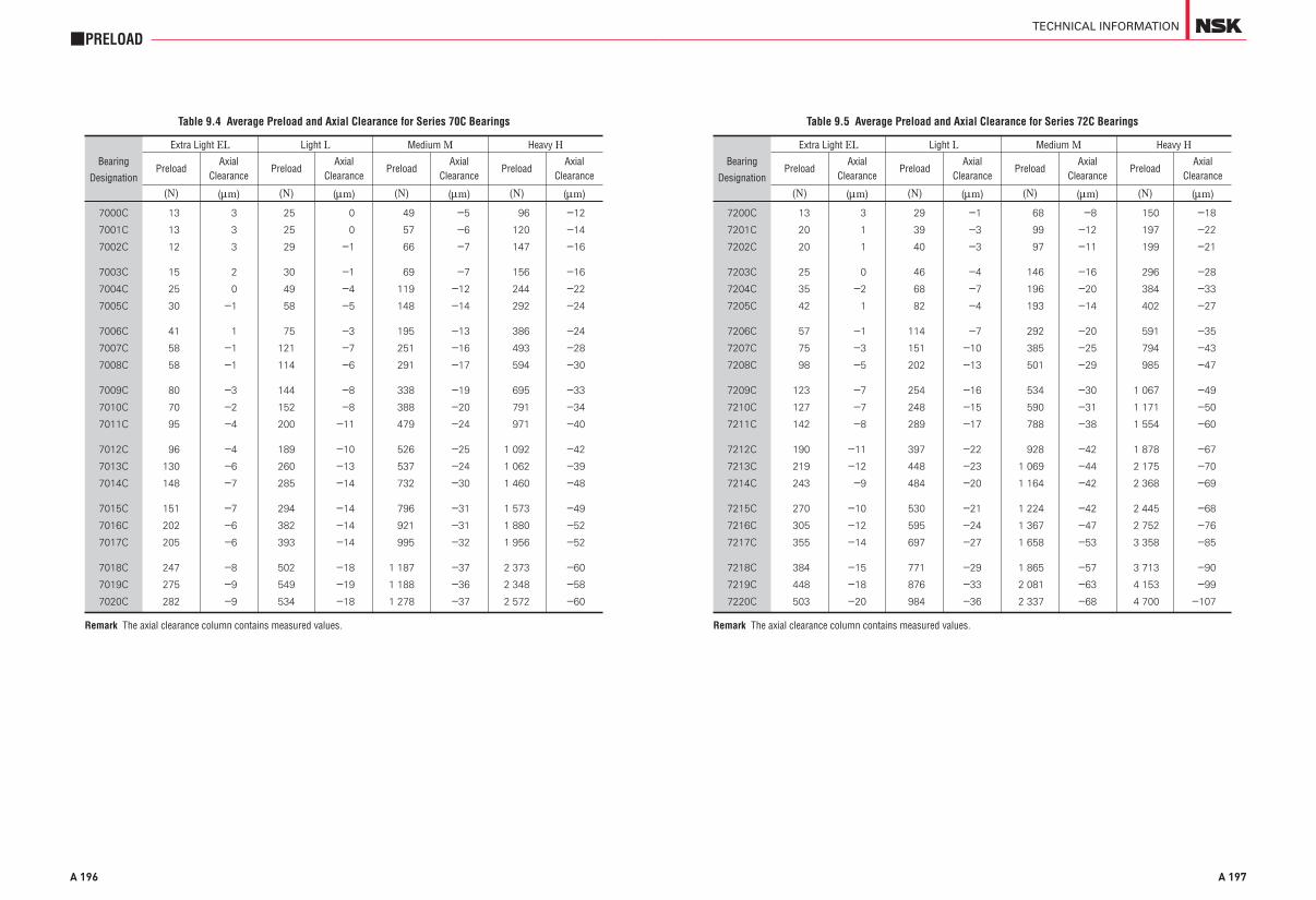
A 196
■PRELOAD
Remark The axial clearance column contains measured values.
Table 9.4 Average Preload and Axial Clearance for Series 70C Bearings
Bearing
Designation
Extra Light EL Light L Medium M Heavy H
PreloadAxial
ClearancePreload
AxialClearance
PreloadAxial
ClearancePreload
AxialClearance
(N) (mm) (N) (mm) (N) (mm) (N) (mm)
7000C
7001C
7002C
7003C
7004C
7005C
7006C
7007C
7008C
7009C
7010C
7011C
7012C
7013C
7014C
7015C
7016C
7017C
7018C
7019C
7020C
13
13
12
15
25
30
41
58
58
80
70
95
96
130
148
151
202
205
247
275
282
3
3
3
2
0
-1
1
-1
-1
-3
-2
-4
-4
-6
-7
-7
-6
-6
-8
-9
-9
25
25
29
30
49
58
75
121
114
144
152
200
189
260
285
294
382
393
502
549
534
0
0
-1
-1
-4
-5
-3
-7
-6
-8
-8
-11
-10
-13
-14
-14
-14
-14
-18
-19
-18
49
57
66
69
119
148
195
251
291
338
388
479
526
537
732
796
921
995
1 187
1 188
1 278
-5
-6
-7
-7
-12
-14
-13
-16
-17
-19
-20
-24
-25
-24
-30
-31
-31
-32
-37
-36
-37
96
120
147
156
244
292
386
493
594
695
791
971
1 092
1 062
1 460
1 573
1 880
1 956
2 373
2 348
2 572
-12
-14
-16
-16
-22
-24
-24
-28
-30
-33
-34
-40
-42
-39
-48
-49
-52
-52
-60
-58
-60
A 197
TECHNICAL INFORMATION
Table 9.5 Average Preload and Axial Clearance for Series 72C Bearings
Bearing
Designation
Extra Light EL Light L Medium M Heavy H
PreloadAxial
ClearancePreload
AxialClearance
PreloadAxial
ClearancePreload
AxialClearance
(N) (mm) (N) (mm) (N) (mm) (N) (mm)
7200C
7201C
7202C
7203C
7204C
7205C
7206C
7207C
7208C
7209C
7210C
7211C
7212C
7213C
7214C
7215C
7216C
7217C
7218C
7219C
7220C
13
20
20
25
35
42
57
75
98
123
127
142
190
219
243
270
305
355
384
448
503
3
1
1
0
-2
1
-1
-3
-5
-7
-7
-8
-11
-12
-9
-10
-12
-14
-15
-18
-20
29
39
40
46
68
82
114
151
202
254
248
289
397
448
484
530
595
697
771
876
984
-1
-3
-3
-4
-7
-4
-7
-10
-13
-16
-15
-17
-22
-23
-20
-21
-24
-27
-29
-33
-36
68
99
97
146
196
193
292
385
501
534
590
788
928
1 069
1 164
1 224
1 367
1 658
1 865
2 081
2 337
-8
-12
-11
-16
-20
-14
-20
-25
-29
-30
-31
-38
-42
-44
-42
-42
-47
-53
-57
-63
-68
150
197
199
296
384
402
591
794
985
1 067
1 171
1 554
1 878
2 175
2 368
2 445
2 752
3 358
3 713
4 153
4 700
-18
-22
-21
-28
-33
-27
-35
-43
-47
-49
-50
-60
-67
-70
-69
-68
-76
-85
-90
-99
-107
Remark The axial clearance column contains measured values.

A 198
■PRELOAD
9.5.2 Preload of Thrust Ball Bearings
When the balls in thrust ball bearings rotate at relatively high speeds, sliding due to gyroscopic moments on the balls may occur. The larger of the two values obtained from Equations (9.1) and (9.2) below should be adopted as the minimum axial load in order to prevent such sliding:
Fa min= ( )2 . . . . . . . . . . . . . . . . . . . . . . . . . (9.1)
Fa min= . . . . . . . . . . . . . . . . . . . . . . . . . . . . . . . . . (9.2)
where Fa min : Minimum axial load (N), {kgf} C0a : Basic static load rating (N), {kgf} n : Speed (min–1) Nmax : Limiting speed (oil lubrication) (min–1)
9.5.3 Preload of Spherical Thrust Roller Bearings
When spherical thrust roller bearings are used, damage such as scoring may occur due to sliding between the rollers and outer ring raceway. The minimum axial load Fa min necessary to prevent such sliding is obtained from the following equation:
Fa min= . . . . . . . . . . . . . . . . . . . . . . . . . . . . . . . . . (9.3)
C0a
1000
C0a
1000C0a
100n
Nmax
A 199
TECHNICAL INFORMATION

A 200
■PRELOAD
9.6 Technical Data9.6.1 Load and Displacement of Position-Preloaded
Bearings
Bearing arrangements refer to multiple identical ball or tapered roller bearings mounted side by side as a set.When two bearings are used, they are often referred to as paired mountings or duplex bearings.In bearing arrangements for machine tool spindles, single-row angular contact ball bearings are most often used for their high rigidity to reduce bearing displacement under load.Paired mountings fall into three types: back-to-back, with load lines that diverge toward the bearing axis; face-to-face, with load lines that converge toward the bearing axis; and tandem, with parallel load lines. The designations for these arrangements are DB, DF, and DT respectively (Fig. 9.7).
Different arrangements are used depending on the application. DB and DF arrangements can take axial loads in either direction. Since the distances of the load centers of DB arrangements are longer than those of DF arrangements, they are widely used in applications where moment loads occur. DT arrangements can only take axial loads in one direction; however, because the two bearings share load equally between them, this type can be used when load in one direction is large.By selecting DB or DF arrangements preset with proper preloads, radial and axial displacement of the bearing inner and outer rings can be reduced as much as possible (DT arrangements can not be preloaded in this way). The amount of preload can be adjusted by changing the clearance between bearings da0, as shown in Figs. 9.9 to 9.11. Preloads are divided into four graduated classifications: Extra Light (EL), Light (L), Medium (M), and Heavy (H). DB and DF arrangements are often used for applications where shaft misalignments and displacements due to load must be minimized. Arrangements of three bearings (triplex) are designated DBD, DFD, and DTD, as shown in Fig. 9.8. Sets of four or five bearings can also be used depending on application requirements. Paired mountings are often used with a preload. Since preload affects affects various things, such as the rise in bearing temperature during operation, torque, bearing noise, and especially bearing life, it is extremely important to avoid applying excessive preload.
da=c Fa2/3 . . . . . . . . . . . . . . . . . . . . . . . . . . . . . . . . . . . . . . (9.4)
where c: Constant depending on the bearing type and dimensions.
Fig. 9.9 shows the preload curves of a DB arrangement, and Figs. 9.10 and 9.11 show preload curves for a DBD arrangement. If the inner rings of a paired mounting as in Fig. 9.9 are pressed axially, A-side and B-side bearings are deformed by da0A and da0B respectively and the clearance (between the inner rings) da0 becomes zero. This condition means that preload Fa0 is applied on the arrangement. If external axial load Fa is applied on the preloaded arrangement from the A-side, then the A-side bearing will be deformed by an additional da1 and the displacement of B-side bearing will be reduced to the same amount as the A-side bearing displacement da1. Therefore, the displacements of A- and B-side bearings are daA = da0A + da1 and daB = da0B + da1 respectively. In other words, the load on the A-side bearing including preload is Fa0 + Fa – Fa’ and that on the B-side is Fa0 – Fa’.
A 201
TECHNICAL INFORMATION
Fig. 9.7 Paired Mounting Bearing Arrangements
Fig. 9.8 Triplex Bearing Arrangements
Fig. 9.9 Preload Graph of DB Back-to-Back Arrangement

A 202
■PRELOAD
If the bearing set has an applied preload, the A-side bearing should have sufficient life and load capacity for an axial load (Fa0+Fa–Fa’) under operating speed conditions. The axial clearance da0 is shown in Tables 9.3 to 9.5 of Section 9.5.1 (Pages A195 to A197).
Fig. 9.10 shows external axial load Fa applied on AA-side bearings. The axial loads and displacements of AA- and B-side bearings are summarized in Table 9.6.
Fig. 9.11 shows external axial load Fa applied on an A-side bearing. The axial loads and displacements of A- and BB-side bearings are summarized in Table 9.7.
Figs. 9.12 to 9.17 show the relationship of axial load to axial displacement for DB and DBD arrangements of 7018C and 7018A bearings under several preload ranges.
Fig. 9.10 Preload Graph for a DBD Arrangement (Axial Load Applied From the AA-Side)
Table 9.6
Direction Displacement Axial load
AA-side da0A+da1 Fa0+Fa-Fa′B-side da0B-da1 Fa0-Fa′
Table 9.7
Direction Displacement Axial load
A-side da0A+da1 Fa0+Fa-Fa′BB-side da0B-da1 Fa0-Fa′
A 203
TECHNICAL INFORMATION
Fig. 9.11 Preload Graph for a DBD Arrangement (Axial Load Applied From A-Side)

A 204
■PRELOAD
Fig. 9.12
Fig. 9.13
Axial load Fa
Axial load Fa
Axi
al d
ispl
acem
ent d a
(mm
)A
xial
dis
plac
emen
t d a
(mm
)
A 205
TECHNICAL INFORMATION
Fig. 9.14
Remark The (●) mark on the axial load or displacement curve indicates the point where the preload is zero. Therefore, if the axial load is larger than this, the opposed bearing does not impose a load.
Axial load Fa
Axi
al d
ispl
acem
ent d a
(mm
)

A 206
■PRELOAD
Fig. 9.16
Fig. 9.15
Axial load Fa
Axial load Fa
Axi
al d
ispl
acem
ent d a
(mm
)A
xial
dis
plac
emen
t d a
(mm
)
A 207
TECHNICAL INFORMATION
Fig. 9.17
Remark The (●) mark on the axial load or displacement curve indicates the point where the preload is zero. Therefore, if the axial load is larger than this, the opposed bearing does not impose a load.
Axial load Fa
Axi
al d
ispl
acem
ent d a
(mm
)

A 208
■PRELOAD
9.6.2 Axial Displacement of Deep Groove Ball Bearings
When an axial load Fa is applied to a radial bearing with contact angle a0 and the inner ring is displaced da, the center of the inner ring raceway radius Oi is also moved to Oi’ resulting in contact angle a as shown in Fig. 9.18. If dN represents the elastic deformation of the raceway and ball in the direction of the rolling element load Q, Equation (9.5) is derived from Fig. 9.18.
(m0+dN)2=(m0·sina0+da)2+(m0·cosa0)2
\ dN=m0 sina0+ 2
+cos2a0– 1 ............. (9.5)
In addition, the following relationship exists between rolling element load Q and elastic deformation dN.
Q=KN·dN3/2 .................................................. (9.6)
where KN: Constant depending on bearing material, type, and dimensions
If we introduce the relation of
m0= + – 1 Dw=B ·Dw
Equations (9.5) and (9.6) are
Q=KN (B ·Dw)3/2 (sina0+h)2+cos2a0–1 3/2
where h= =
If we introduce the relation of KN=K ·
Q=K ·Dw2 (sina0+h)2+cos2a0–1
3/2 ................ (9.7)
On the other hand, the relation between bearing axial load and rolling element load is shown in Equation (9.8) using Fig. 9.19:
Fa=Z ·Q ·sina .............................................. (9.8)
Based on Fig. 9.18, we obtain,
(m0+dN) sina=m0·sina0+da
(⎫⎪⎬⎪⎭
)da
m0
⎫⎪⎬⎪⎭
re
Dw( ri
Dw)
√ ⎫⎬⎭
⎫⎬⎭
da
m0
da
B ·DwDw
B3/2√—
√————————— ⎫⎬⎭
⎫⎬⎭
\ sina= =
If we substitute Equation (9.5),
sina= ............................ (9.9)
In other words, the relation between the bearing axial load Fa and axial displacement da can be obtained by substituting Equations (9.7) and (9.9) for Equation (9.8).
Fa=K ·Z ·Dw2 ·
..................................... (9.10)
where K: Constant depending on bearing material and design
Dw: Ball diameter Z: Number of balls a0: Initial contact angle The initial contact angle for single-row
deep groove ball bearings can be obtained using Equation (5) on Page C012
Actual axial deformation varies depending on bearing mounting conditions and factors such as the material and thickness of the shaft and housing and bearing fitting. For more details, consult with NSK.
m0·sina0+da
m0+dN
sina0+h
1+ dN
m0
sina0+h(sina0+h)2+cos2a0√—————————
(sina0+h)2+cos2a0–1 3/2μ(sina0+h)
(sina0+h)2+cos2a0√—————————√————————— ⎫
⎬⎭
⎫⎬⎭
A 209
TECHNICAL INFORMATION
Fig. 9.18
Fig. 9.19

A 210
■PRELOAD
Fig. 9.20 shows the relation between axial load and axial displacement for Series 6210 and 6310 single-row deep groove ball bearings with initial contact angles of 0°, 10°, and 15°. The larger the initial contact angle a0, the more rigid the bearing will be in the axial direction and the smaller the difference between the axial displacements of 6210 and 6310 under identical axial load. The initial contact angle a0 depends on the groove radius and the radial clearance.
Fig. 9.21 shows the relation between axial load and axial displacement for Series 72 angular contact ball bearings with initial contact angles of 15° (C), 30° (A), and 40° (B). Series 70 and 73 bearings with identical contact angles and bore diameters can be considered to have almost the same values as Series 72 bearings.Angular contact ball bearings that sustain loads in the axial direction must maintain their running accuracy and reduce elastic deformation from applied loads when used as multiple bearing arrangements with a preload.
To determine the preload to keep the elastic deformation caused by applied loads within the required limits, it is important to know the characteristics of load vs. deformation. The relationship between load and displacement can be expressed by Equation (9.10) as Fa∝da
3/2 or da∝Fa2/3.
In other words, axial displacement da is proportional to axial load Fa to the 2/3 power. When this axial load index is less than one, relative axial displacement will be small, with only a small increase in axial load (Fig. 9.21). The underlying reason for applying a preload is to reduce the amount of displacement.
A 211
TECHNICAL INFORMATION
Fig. 9.20 Axial Load and Axial Displacement of Deep Groove Ball Bearings
Fig. 9.21 Axial Load and Axial Displacement of Angular Contact Ball Bearings
Axial load Fa
Axial load Fa
Axi
al d
ispl
acem
ent d a
(mm
)
Axi
al d
ispl
acem
ent d a
(mm
)

A 212
■PRELOAD
9.6.3 Axial Displacement of Tapered Roller Bearings
Tapered roller bearings are widely used in pairs like angular contact ball bearings. Take care when selecting appropriate tapered roller bearings.For example, the bearings of machine-tool head spindles and automobile differential pinions are preloaded to increase shaft rigidity.When a bearing with an applied preload is to be used, it is essential to have some knowledge of the relationship between axial load and axial displacement. For tapered roller bearings, the axial displacement calculated using Palmgren’s method in Equation (9.11) generally agrees well with actual measured values.Actual axial deformation varies depending on the bearing mounting conditions, such as the material and thickness of the shaft and housing and the bearing fitting. For more details, consult with NSK.
da= · (N) ..... (9.11)
= · {kgf}
where, da: Axial displacement of inner, outer ring (mm)
a: Contact angle...1/2 the outer ring angle (°) (Refer to Fig. 9.22)
Q: Load on rolling elements (N), {kgf}
Q=
Lwe: Length of effective contact on roller (mm)
Fa: Axial load (N), {kgf} Z: Number of rollers
Equation (9.11) can also be expressed as Equation (9.12).
da=Ka·Fa0.9 .................................................. (9.12)
0.000077sina
Q0.9
Lwe0.8
⎫⎪⎪⎬⎪⎪⎭
0.0006sina
Q0.9
Lwe0.8
Fa
Zsina
where,Ka= .................................. (N)
= ............................... {kgf}
Here Ka refers to the coefficient determined by bearing internal design.Axial loads and axial displacement for tapered roller bearings are plotted in Fig. 9.23.The amount of axial displacement of tapered roller bearings is proportional to the axial load raised to the 0.9 power. The displacement of ball bearings is proportional to the axial load raised to the 0.67 power; thus, the preload required to control displacement is much greater for ball bearings than for tapered roller bearings.Take caution not to make the preload indiscriminately large on tapered roller bearings, since too large of a preload can cause excessive heat, seizure, and reduced bearing life.
0.000077(sina)1.9 Z 0.9 Lwe
0.8
0.0006(sina)1.9 Z 0.9 Lwe
0.8
A 213
TECHNICAL INFORMATION
Fig. 9.23 Axial Load and Axial Displacement for Tapered Roller Bearings
Fig. 9.22
Axial load Fa
Axi
al d
ispl
acem
ent d a
(mm
)

A 215
TECHNICAL INFORMATION
10.1 Coefficients of Dynamic Friction ················································ A 216
10.1.1 Bearing Types and Their Coefficients of Dynamic Friction µ ···································································· A 216
10.2 Empirical Equations for Running Torque ······························ A 216
10.3 Technical Data ························································································ A 216
10.3.1 Preload and Starting Torque for Angular Contact Ball Bearings ··································· A 216
10.3.2 Empirical Equations for Running Torque of High-Speed Ball Bearings ·············································· A 218
10.3.3 Preload and Starting Torque for Tapered Roller Bearings ················································ A 220
10.3.4 Empirical Equations for Running Torque of Tapered Roller Bearings ·················································· A 222
10. FRICTION

A 216
■FRICTION
10. FRICTION10.1 Coefficients of Dynamic Friction10.1.1 Bearing Types and Their Coefficients of
Dynamic Friction μ
μ= . . . . . . . . . . . . . . . . . . . . . . . . . . . . . . . . . . . . . . (10.1)
M : Dynamic friction torque(N・mm),{kgf・mm} P : Load on a bearing(dynamic equivalent load)(N),{kgf} d : Shaft diameter, inner ring bore diameter (mm)
10.2 Empirical Equations for Running Torque
M
P ⋅ d2
Deep Groove Ball Bearings 0.0013 Angular Contact Ball Bearings 0.0015 Self-Aligning Ball Bearings 0.0010 Thrust Ball Bearings 0.0011
Cylindrical Roller Bearings 0.0010 Tapered Roller Bearings 0.0022 Spherical Roller Bearings 0.0028
Needle Roller Bearings 0.0015 With Cages
Full Complement Needle 0.0025 Roller Bearings
Spherical Thrust Roller 0.0028 Bearings
Bearing Types Approximate Values of μ
Table 10.1 Coefficients of Dynamic Friction
Load term (determined by bearing type and load) Ml=f1Fdm
where f1 : Coefficient determined by bearing type and load F : Load dm : Pitch circle diameter of rolling elementSpeed term (determined by oil viscosity, amount, speed) Mv=f0 ( 0 n )2/3dm3
where f0 : Coefficient determined by bearing and lubricating method 0 : Kinematic viscosity of oil n : Speed
Dynamicbearingtorque(heat generation)
M=Ml+Mv
ν
ν
10.3 Technical Data10.3.1 Preload and Starting Torque for Angular
Contact Ball BearingsAngular contact ball bearings, like tapered roller bearings, are most often used in pairs rather than alone or in other multiple bearing sets. Back-to-back and face-to-face bearing sets can be preloaded to adjust bearing rigidity. Extra Light (EL), Light (L), Medium (M), and Heavy (H) are standard preloads. Friction torque of the bearing will increase in direct proportion to the preload.The starting torque of angular contact ball bearings is mainly caused by angular slippage between the balls and contact surfaces on the inner and outer rings. Starting torque for the bearing M due to such spin is given by the following equation:
M=Ms·Zsina (mN·m), {kgf·mm} . . . . . . . . . . . (10.2)
where Ms : Spin friction for contact angle a centered on the shaft,
Ms= ms·Q ·a ·E (k)
(mN ·m), {kgf ·mm} ms : Contact-surface slip friction coefficient Q : Load on rolling elements (N), {kgf} a : (1/2) of contact-ellipse major axis (mm)
E (k): With k= 1– 2
as the population parameter, second class complete ellipsoidal integration
b : (1/2) of contact-ellipse minor axis (mm) Z : Number of balls a : Contact angle (°)
Actual measurements with 15° angular contact ball bearings correlate well with calculated results using ms
= 0.15 in Equation (10.2). Fig. 10.1 shows the calculated friction torque for Series 70C and 72C bearings.
38
ba( )
A 217
TECHNICAL INFORMATION
Fig. 10.1 Preload and Starting Torque for DF and DB Angular Contact Ball Bearing (a=15°) Arrangments
Preload Fa

A 218
■FRICTION
10.3.2 Empirical Equations for Running Torque of High-Speed Ball Bearings
Empirical equations are presented below for the running torque of high speed ball bearings subject to axial loading and jet lubrication. These equations are based on the results of tests of angular contact ball bearings with bore diameters of 10 to 30 mm, but they can be extrapolated to larger bearings.Running torque M can be obtained as the sum of a load term Ml and speed term Mv as follows:
M = Ml + Mv (mN ·m), {kgf · mm} . . . . . . . . . . (10.3)
Load term Ml refers to friction with no relation to speed or fluid friction and is expressed by the experimentally-based Equation (10.4).
Ml = 0.672 μ 10–3Dpw0.7Fa
1.2 (mN · m) . . . . . . . . (10.4) = 1.06 μ 10–3Dpw
0.7Fa1.2 {kgf · mm}
where, Dpw: Pitch diameter of rolling elements (mm) Fa: Axial load (N), {kgf}
Speed term Mv refers to fluid friction, which depends on angular speed and is expressed by Equation (10.5).
Mv = 3.47 μ 10–10Dpw3ni
1.4ZBaQb (mN · m)
= 3.54 μ 10–11Dpw3ni
1.4ZBaQb {kgf · mm}
. . . . . . . . . . . . . . . . . . . . . . . . . . . . . . . . . . . . . . . . . . . . . (10.5)
where, ni: Inner ring speed (min–1) ZB: Absolute viscosity of oil at outer ring
temperature (mPa · s), {cp} Q: Oil flow rate (kg/min)
Exponents a and b, which affect oil viscosity and flow rate factors, depend only on angular speed and are given by Equations (10.6) and (10.7) as follows:
⎫⎪⎬⎪⎭
a = 24ni–0.37 . . . . . . . . . . . . . . . . . . . . . . . . . . . . . . . . . . . . . (10.6)
b = 4 μ 10–9ni1.6 + 0.03 . . . . . . . . . . . . . . . . . . . . . . . . . (10.7)
An example estimation for the running torque of high-speed ball bearings is shown in Fig. 10.2. A comparison of values calculated using these equations and actual measurements is shown in Fig. 10.3. When the contact angle exceeds 30°, the influence of spin friction becomes large, so the running torque given by the equations will be low.
Calculation ExampleObtain the running torque of high speed angular contact ball bearing 20BNT02 (f20 μ f47μ 14) under the following conditions:
ni = 70 000 min–1
Fa = 590 N, {60 kgf}Lubrication: Jet, oil viscosity:
10 mPa ·s {10 cp}oil flow: 1.5 kg/min
From Equation (10.4),Ml = 0.672 μ 10–3Dpw
0.7Fa1.2
= 0.672 μ 10–3 μ 33.50.7 μ 5901.2
= 16.6 (mN ·m)Ml = 1.06 μ 10–3 μ 33.50.7 μ 601.2
= 1.7 {kgf ·mm}
From Equations (10.6) and (10.7),a = 24ni
–0.37
= 24 μ 70 000–0.37 = 0.39b = 4 μ 10–9ni
1.6 + 0.03 = 4 μ 10–9 μ 70 0001.6 + 0.03 = 0.26
From Equation (10.5),Mv = 3.47 μ 10–10Dpw
3ni1.4ZB
aQb
= 3.47 μ 10–10 μ 33.53 μ 70 0001.4 μ 100.39 μ 1.50.26
= 216 (mN ·m)
Mv = 3.54 μ 10–11 μ 33.53 μ 70 0001.4 μ 100.39 μ 1.50.26
= 22.0 {kgf ·mm}
M = Ml + Mv = 16.6 + 216 = 232.6 (mN·m)M = Ml + Mv = 1.7 + 22 = 23.7 {kgf·mm}
A 219
TECHNICAL INFORMATION
Fig. 10.2 Typical Test Example
Fig. 10.3 Comparison of Actual Measurements and Calculated Values
Inner ring speed ni (min-1)
Out
er r
ing
tem
pera
ture
(°C
)
Run
ning
tor
que
M
Oil temperature: 50 °CAxial load Fa: 363 N {37 kgf}
Calculated Running torque M
Mea
sure
d R
unni
ng t
orqu
e M
The contact angles of the bearings above range from 15 to 25 degrees.
Remark
High-Speed AngularContact Ball Bearings
Axial Load

A 220
■FRICTION
10.3.3 Preload and Starting Torque for Tapered Roller Bearings
The balance of loads on the bearing rollers when a tapered roller bearing is subjected to axial load Fa is expressed by the following three Equations:
Qe= . . . . . . . . . . . . . . . . . . . . . . . . . . . . . . . . . . . . (10.8)
Qi=Qecos2b= Fa . . . . . . . . . . . . . . . . . . . . (10.9)
Qf=Qesin2b= Fa . . . . . . . . . . . . . . . . . . (10.10)
where Qe : Rolling element load on outer ring (N), {kgf}
Qi : Rolling element load on inner ring (N), {kgf}
Qf : Rolling element load on inner ring large end rib, (N), {kgf} (assume Qf ^ Qi)
Z : Number of rollers a : Contact angle...one-half included outer
ring angle (°) b : One-half the tapered roller angle (°) Dw1 : Roller large end diameter (mm) (Fig.
10.4) e : Contact point between roller end and rib
(Fig. 10.4)
As represented in Fig. 10.4, when circumferential load F is applied to the bearing outer ring and the roller turns in the direction of the applied load, the starting torque for contact point C relative to instantaneous center A becomes e meQf.
Therefore, the balance of frictional torque is
Dw1F=e meQf (mN ·m), {kgf ·mm} . . . . . . . . . (10.11)
where me: Friction coefficient between inner ring large rib and roller end face
Fa
Z sin a
cos 2bZ sin a
sin 2bZ sin a
Starting torque M for one bearing is given byM=F Z l
= Fa
(mN ·m), {kgf ·mm} . . . . . . . (10.12)
because Dw1=2 OB sin b, and l=OB sin a.If we substitute these into Equation (10.12), we obtain
M=e me cosb Fa (mN ·m), {kgf ·mm} . . . . . . . . . . . . . . . . . . . . . . . . . . . . . (10.13)
Starting torque M is sought considering only the slip friction between the roller end and the inner ring large-end rib. However, when the load on a tapered roller bearing reaches or exceeds a certain level (around the preload), the slip friction in the space between the roller end and inner ring large end rib becomes the decisive factor for bearing starting torque, and the torque caused by other factors can be ignored. Values for e and b in Equation (10.12) are determined by bearing design. Consequently, by assuming a value for me, the starting torque can be calculated.The values for me and for e must be considered as a dispersion; thus, even bearings with the same number can have quite diverse individual starting torques. When using a value for e determined by the bearing design, the average value for the bearing starting torque can be estimated using me = 0.20, which is the average value determined from various test results.Fig. 10.5 shows the results of calculations for various tapered roller bearing series.
e me l sin 2bDw1 sin a
A 221
TECHNICAL INFORMATION
Fig. 10.4
Fig. 10.5 Axial Load and Starting Torque for Tapered Roller Bearings
Axial Load Fa
Sta
rtin
g to
rque
M

A 222
■FRICTION
10.3.4 Empirical Equations for Running Torque of Tapered Roller Bearings
When tapered roller bearings operate under axial load, the torque of tapered roller bearings is based on the following two kinds of resistance, which are the major components of friction:(1) Rolling resistance (friction) of rollers with outer or
inner ring raceways—elastic hysteresis and viscous rolling resistance of EHL
(2) Sliding friction between inner ring ribs and roller ends.
When an axial load Fa is applied on tapered roller bearings, the loads shown in Fig. 10.6 are applied on the rollers.
Qe≒Qi= . . . . . . . . . . . . . . . . . . . . . . . . . . . . (10.14)
Qf = . . . . . . . . . . . . . . . . . . . . . . . . . . . . . . (10.15)
where Qe: Rolling element load on outer ring Qi: Rolling element load on inner ring Q f: Rolling element load on inner ring large
end rib Z: Number of rollers a: Contact angle…One-half included outer
ring angle b: One-half tapered roller angle
For simplicity, Fig. 10.7 shows a model using the average diameter Dwe along with the following variables:
Mi, Me: Rolling resistance (moment) Fsi, Fse, Fsf: Sliding friction Ri, Re: Radii at center of inner and
outer ring raceways e: Contact height of roller end
face with rib
When the balance of sliding friction and moments on the rollers are considered as represented in Fig 10.7, the following equations are obtained:
Fse–Fsi=Fsf . . . . . . . . . . . . . . . . . . . . . . . . . . . . . . . . . . . . (10.16)
Fa
Z sina
Fa sin 2bZ sina
Mi+Me= Fse+ Fsi+ –e Fsf
. . . . . . . . . . . . . . . . . . . . . . . . . . . . . . . (10.17)
When the running torque M applied on the outer (inner) ring is calculated using Equations (10.16) and (10.17) and multiplied by the number of rollers Z, the following is obtained:
M=Z (Re Fse–Me)
= (Re Mi+RiMe) + Re e Fsf
=MR+MS
Therefore, the rolling friction on the raceway surface MR and sliding friction on the ribs MS are separately obtained.
Dw
2Dw
2 ( )Dw
2
ZDw
ZDw
A 223
TECHNICAL INFORMATION
Fig. 10.6 Loads Applied on Roller
Fig. 10.7 Parts Where Friction is Generated

A 224
■FRICTION
The running torque M of a tapered roller bearing can be obtained from the rolling friction on the raceway MR and sliding friction on the ribs MS.
M=MR+MS= (Re Mi+Ri Me )
+ Re e Fsf . . . . . . . . . . . . . . . . . . . . . . . . . . . . . . . . (10.18)
Sliding Friction on Rib MS
As a part of MS, Fsf refers to the tangential load caused by sliding, so we can write Fsf = mQ f using the coefficient of dynamic friction m. Further, by substituting in axial load Fa, the following equation is obtained:
MS = e m cosb Fa . . . . . . . . . . . . . . . . . . . . . . . . . . . . . (10.19)
This is identical to the equation for starting torque, but m is not constant and decreases depending on operating conditions and running-in. For this reason, Equation (10.19) can be rewritten as follows:
MS=e m0 cosb Fa f ’ (L, t, s) . . . . . . . . . . . . . . . . (10.20)
where m0 is approximately 0.2 and f ’ (L, t, s) is a function that decreases with running in and oil film formation but is set equal to one at starting.
Rolling Friction on Raceway Surface MR
Most of the rolling friction on the raceway is from viscous oil resistance (EHL rolling resistance) corresponding to Mi and Me in Equation (10.18). A theoretical equation exists but should be corrected based on the results of experiments. The following equation includes corrective terms:
Mi, e= f (w)
(G ·U)0.658W 0.0126R2Lwe i, e
. . . . . . . . . . . . . . . (10.21)
f (w)= 0.3
. . . . . . . . . . . . . . . . . . . (10.22)
ZDw
ZDw
[ ( 11+0.29L0.78
4.318a0
)]
kFa
E’ DwLweZsina( )
Therefore, MR can be obtained using Equations (10.21) and (10.22) together with the following equation:
MR= (Re Mi+Ri Me )
Running Torque of Bearings MFrom these, the running torque of tapered roller bearings M is given by Equation (10.23).
M= (Re Mi+Ri Me ) +e m0 cosb Fa f ’ (L, t, s)
. . . . . . . . . . . . . . . . . . . . . . . . . . . . (10.23)
As shown in Figs. 10.8 and 10.9, the values obtained using Equation (10.23) correlate rather well with actual measurements; therefore, estimation of running torque with good accuracy is possible. Please consult NSK with any questions or concerns.
[Symbol Definitions]G, W, U: EHL dimensionless parametersL: Coefficient of thermal loada0: Pressure coefficient of lubricating oil
viscosityR: Equivalent radiusk: ConstantE’: Equivalent elastic modulusa: Contact angle (One-half included outer
ring angle)Ri , Re : Inner and outer ring raceway radii
(center)b: Half angle of rolleri, e: Indication of inner ring or outer ring
respectivelyLwe: Effective roller length
ZDw
ZDw
A 225
TECHNICAL INFORMATION
Fig. 10.8 Comparison of Estimated Values With Actual Measurements
Fig. 10.9 Viscosity Variation and Running Torque
Speed ni (min-1)
Bearing temperature (°C)
Run
ning
tor
que
M
Estimated values (Equation(10.23))
Estimated values (Equation(10.23))
Run
ning
tor
que
M

A 227
TECHNICAL INFORMATION
11.1 Purposes of Lubrication ··································································· A 228
11.2 Lubricating Methods ··········································································· A 228
11.2.1 Grease Lubrication ···································································· A 228
(1) Grease Quantity ················································································ A 228
(2) Replacement of Grease ······························································· A 229
(3) Replenishment Interval ······························································· A 229
(4) Grease Life of Sealed Ball Bearings ··································· A 231
11.2.2 Oil Lubrication ············································································· A 232
(1) Oil Bath Lubrication ······································································· A 232
(2) Drip-Feed Lubrication ··································································· A 232
(3) Splash Lubrication ·········································································· A 232
(4) Circulating Lubrication ································································ A 233
(5) Jet Lubrication ··················································································· A 234
(6) Oil Mist Lubrication ······································································· A 235
(7) Oil/Air Lubricating Method ························································ A 235
11.3 Lubricants ·································································································· A 236
11.3.1 Lubricating Grease ···································································· A 236
(1) Base Oil ·································································································· A 236
(2) Thickener ······························································································· A 236
(3) Additives ································································································ A 236
(4) Consistency ························································································· A 236
(5) Mixing Different Types of Grease ········································· A 238
11.3.2 Lubricating Oil ············································································· A 238
11.4 Technical Data ························································································ A 240
11.4.1 Brands and Properties of Lubricating Greases ······ A 240
11. LUBRICATION

A 228
■LUBRICATION
11.1 Purposes of LubricationThe main purposes of lubrication are to reduce friction and wear inside the bearings that may cause premature failure. The effects of lubrication may be briefly explained as follows:
(1) Reduction of Friction and WearDirect metallic contact between the basic components of the bearing (bearing rings, rolling elements and cage) is prevented by an oil film that reduces friction and wear in contact areas.
(2) Extension of Fatigue LifeThe rolling fatigue life of bearings depends greatly upon the viscosity and film thickness between the rolling contact surfaces. A heavy film thickness prolongs fatigue life, but life is shortened if the viscosity of the oil is so low that film thickness is insufficient.
(3) Dissipation of Frictional Heat and CoolingCirculation lubrication is used to carry away frictional or absorbed heat, prevent the bearing from overheating, and prevent oil from deteriorating.
(4) OthersAdequate lubrication also helps to prevent foreign material from entering the bearings and guards against corrosion and rusting.
11.2 Lubricating MethodsLubricating methods are first divided into either grease or oil lubrication. Satisfactory bearing performance can be achieved by adopting the lubricating method most suitable for the particular application and operating condition.In general, oil offers superior lubrication; however, grease lubrication allows for a simpler structure around the bearings. A comparison of grease and oil lubrication is given in Table 11.1.
11.2.1 Grease Lubrication(1) Grease QuantityThe quantity of grease to be packed in a housing depends on the housing design and free space, grease characteristics, and ambient temperature. For example, bearings for main shafts of machine tools where the accuracy may be impaired by a small temperature rise require only a small amount of grease.Sufficient grease must be packed inside the bearing including the cage guide face. The amount to be packed inside the the housing depends on the speed of the application:
When bearing speed is 50% or less of the specified limiting speed, fill 1/2 to 2/3 of the free space.When bearing speed is 50% or more of the specified limiting speed, fill 1/3 to 1/2 of the free space.
Table 11. 1 Comparison of Grease and Oil Lubrication
Item Grease Lubrication Oil Lubrication
Housing Structure and Sealing Method
Speed
Cooling Effect
Fluidity
Full Lubricant Replacement
Removal of Foreign Matter
ExternalContamination Due to Leakage
Simple
Limiting speed 65% to 80% that of oil lubrication.
Poor
Poor
Sometimes difficult
Removal of particlesfrom grese is impossible.
Surroundings seldom contaminated by leakage.
May be complex. Careful maintenance required
Higher limiting speed
Heat transter possible using forced oil circulation.
Good
Conpactively easy
Easy
Often leaks without proper countermeasures.Not suitable if external contamination must be avoided.
11. LUBRICATION
A 229
TECHNICAL INFORMATION
(2) Replacement of GreaseGrease, once packed, usually need not be replenished for a long time; however, under severe operating conditions, grease should be frequently replenished or replaced. In such cases, the bearing housing should be designed to facilitate grease replenishment and replacement.When replenishment intervals are short, provide replenishment and discharge ports at appropriate positions so that deteriorated grease is replaced by fresh grease. For example, the housing space on the grease-supply side can be divided into several sections with partitions. The grease on the partitioned side gradually passes through the bearings and old grease forced from the bearing is discharged through a grease valve (Fig. 11.1). If a grease valve is not used, the
space on the discharge side must be larger than the partitioned side so that it can retain old grease, which can be removed periodically by removing the cover.
(3) Replenishment IntervalEven if high-quality grease is used, grease deterioration occurs with time; therefore, periodic replenishment is required. Graphs (1) and (2) in Fig 11.2 show the replenishment time intervals for various bearing types running at different speeds. These graphs show high-quality, lithium-soap mineral oil grease at a bearing temperature of 70 °C under normal load (P/C=0.1).· TemperatureIf the bearing temperature exceeds 70 °C, reduce the replenishment interval by half for every 15 °C increase.· GreaseReplenishment intervals can be extended depending on used grease type, especially for ball bearings. For example, high-quality lithium-soap synthetic oil grease may roughly doubles the replenishment interval shown in Fig.11.2 (1). If the temperature of the bearings is less than 70 °C, the usage of lithium-soap mineral oil grease or lithium-soap synthetic oil grease is appropriate.Please consult NSK for details.· LoadThe replenishment interval depends on the magnitude of the bearing load.Please refer to Fig.11.2 (3) for details.If P/C exceeds 0.16, please consult NSK.
A
AA- A
Fig. 12.1 Combination of Partitioned Grease Fig. 12. 1 Reservoir and Grease ValveFig. 11.1 Combination of Partitioned Grease
Reservoir and Grease Valve

A 230
■LUBRICATION
Fig. 12.2 Grease Replenishment Intervals
(3) Load factor P/C ≤0.06 0.1 0.13 0.16
Load factor 1.5 1 0.65 0.45
h
Speed n min–1
20 000 10 000
8 000
6 0005 0004 000
3 000
2 000
1 000
800
600500400
300
200200 300 400 600 800 1 000 2 000 4 000 6 000 10 000 20 000
20 000
10 000
8 000
6 0005 000
4 000
3 000
2 000
1 000
800
600
400
203040
5060
7080
100120
140160
180220
260300
d=10
Radial Ball BearingsCylindrical Roller Bearings
(1) Radial Ball Bearings, Cylindrical Roller Bearings
Gre
ase
Rep
leni
shm
ent I
nter
val t
f
h
Speed n min–1
100
200
300
400500600
800
1 000
2 000
3 000
4 000
5 000
7 000
10 000
10 0006 0004 0002 0001 000600400300200100
30
4050
6070
80100
120140
160200
240280
340420
500
d=20
(2) Tapered Roller Bearings, Spherical Roller Bearings
Gre
ase
Rep
leni
shm
ent I
nter
val t
f
Fig. 11.2 Grease Replenishment Intervals
A 231
TECHNICAL INFORMATION
(4) Grease Life of Sealed Ball BearingsWhen grease is packed into single-row deep groove ball bearings, the grease life may be estimated using Equation (11.1), Equation (11.2), or Fig. 11.3:(General purpose grease (1))
log t = 6.54 – 2.6 n
Nmax – (0.025 – 0.012
nNmax )T
……………………(11.1)(Wide-range grease (2))
log t = 6.12 – 1.4 n
Nmax – (0.018 – 0.006
nNmax
)T ……………………(11.2)
where t : Average grease life (h) n : Speed (min–1) Nmax : Limiting speed with grease lubrication
(min–1) (values for ZZ and VV types are listed in the
bearing tables) T : Operating temperature °CEquation (11.1), Equation (11.2), and Fig. 11.3 apply under the following conditions:(a) Speed n
0.25 ≤ n
Nmax ≤ 1
when n
Nmax <0.25, assume n
Nmax = 0.25
(b) Operating Temperature TFor general-purpose grease (1) 70 °C ≤ T ≤110 °C
For wide-range grease (2)
70 °C ≤ T ≤130 °C
When T < 70 °C assume T = 70 °C
(c) Bearing LoadsThe bearing loads should be about 1/10 or less the basic load rating Cr. Notes (1) Mineral-oil base greases (e.g. lithium-soap
base grease) often used around – 10 to 110 °C.
Notes (2) Synthetic-oil base greases are usable over a wide temperature range around –40 to 130 °C.
h
n/Nmax
150 000
100 000
50 000
20 000
10 000
5 000
3 000
2 000
1 000
500
2000.25 0.3 0.4 0.5 0.6 0.7 0.8 0.9 1
8080 9090 100100
110
110120
130
T=70T=70
Aver
age
Gre
ase
Life
t
General-purpose greaseWide-range grease
Fig. 11.3 Grease Life of Sealed Ball Bearings

A 232
■LUBRICATION
11.2.2 Oil Lubrication(1) Oil-Bath LubricationOil-bath lubrication is widely used with low or medium speeds. The oil level should be at the center of the lowest rolling element. Ideally, provide a sight gauge so the proper oil level may be maintained (Fig. 11.4)
(2) Drip-Feed LubricationDrip-feed lubrication is widely used for small ball bearings operated at relatively high speeds. As shown in Fig. 11.5, oil is stored in a visible oiler. The oil drip rate is controlled with a screw in the top.
(3) Splash LubricationWith this method, oil is splashed onto the bearings by gears or a simple rotating disc installed near bearings without submerging the bearings in oil.It is commonly used in automobile transmissions and final drive gears. Fig. 11.6 shows this lubricating method used on a reduction gear.
Fig. 11.4 Oil-Bath Lubrication
Fig. 11.5 Drip-Feed Lubrication
Fig. 11.6 Splash Lubrication
A 233
TECHNICAL INFORMATION
(4) Circulating LubricationCirculating lubrication is commonly used for high-speed operation requiring bearing cooling and for bearings used at high temperatures. As shown in Fig. 11.7 (a), oil is supplied by a pipe on the right side. The oil travels through the bearing and drains out through a pipe on the left. After being cooled in a reservoir, the oil returns to the bearing through a pump and filter.The oil discharge pipe should be larger than the supply pipe so that excessive oil does not back up in the housing.
Fig. 11.7 Circulating Lubrication
Oil
(a)
Oil
(b)
Oil
(c)

A 234
■LUBRICATION
(5) Jet LubricationJet lubrication is often used for ultra-high-speed bearings with a dmn valve (dm: pitch diameter of rolling element set in mm; n: rotational speed in min–1) exceeding one million, such as the bearings in jet engines. Lubricating oil is sprayed under pressure from one or more nozzles directly into the bearing.Fig. 11.8 shows an example of ordinary jet lubrication. The lubricating oil is sprayed on the inner ring and cage guide face. In high-speed operation, the air surrounding the bearing rotates with it, causing the oil jet to be deflected. The jetting speed of the oil from the nozzle should be more than 20 % of the circumferential speed of the inner ring outer surface, or cage guide face.More uniform cooling and a better temperature distribution is achieved using more nozzles for a given amount of oil. The oil should be forcibly discharged so that the agitating resistance of the lubricant can be reduced and the oil can effectively carry away the heat.
Fig. 11.8 Jet Lubrication
(a)
(b) (c)
Oil
Oil
Oil
Oil
A 235
TECHNICAL INFORMATION
(6) Oil-Mist LubricationOil-mist lubrication, or oil fog lubrication, utilizes an oil mist sprayed into a bearing. This method has the following advantages:(a) Because of the small quantity of oil required, the oil agitation resistance is small, and higher speeds are possible.(b) Contamination of the vicinity around the bearing is limited because the oil leakage is small.(c) It is relatively easy to continuously supply fresh oil; therefore, bearing life is extended.This lubricating method is used for bearings in the high-speed spindles of machine tools, high-speed pumps, roll necks of rolling mills, and so on (see example in Fig. 11.9).Please consult NSK regarding oil-mist lubrication of large bearings.
(7) Oil-Air Lubricating MethodWith the oil-air lubricating method, a very small amount of oil is discharged intermittently by a constant-quantity piston into a pipe carrying a constant flow of compressed air. The oil flows along the wall of the pipe and approaches a constant flow rate.The major advantages of oil-air lubrication are as follows:(a) The minimum necessary amount of oil is supplied, making this method suitable for high speeds because less heat is generated.(b) Since oil is fed continuously, bearing temperature remains stable. Also, because of the small amount of oil, there is almost no atmospheric pollution.
(c) Only fresh oil is fed to the bearings, so oil deterioration need not be considered.(d) Compressed air is constantly fed to the bearings and keeps internal pressure high. This prevents the entry of dust, cutting fluid, etc.For these reasons, this method is used in the main spindles of machine tools and other high speed-applications (see example in Fig. 11.1O).
Fig. 11.9 Oil-Mist Lubrication
Oil/air discharge ports × 2 places
Oil/air inlets × 5 places
Fig. 11.10 Oil-Air Lubrication

A 236
■LUBRICATION
Note (1) The grease dropping point is that temperature at which a grease heated in a specified small container becomes sufficiently fluid to drip.
Lithium Grease
Li Soap
Mineral Oil Properties
Diester Oil, Polyatomic Ester Oil
Silicone Oil
170 to 195 170 to 195 200 to 210
–20 to +110 –50 to +130 –50 to +160
70 100 60
Good Good Good
Fair Fair Poor
Good Good Good
Good Good Poor
Remarks
General-purpose grease used for numerous applications
Good low-temperature and torque characteristics. Often used for small motors and instrument bearings. Monitor for rust caused by insulation varnish.
Mainly used for high temperature applications. Unsuitable for bearings at high and low speeds, under heavy loads, or with numerous sliding-contact areas (roller bearings, etc.)
Table 11.2
Note (1) The values listed are percentages of the limiting speeds given in the bearing tables.
Name(Popular Name)
Thickener
BaseOil
Dropping Point,°CWorking Temperatures, °CWorking Speed, %(1)Mechanical StabilityPressure Resistance
Water Resistance
Rust Prevention
11.3 Lubricants11.3.1 Lubricating GreaseGrease is a semisolid lubricant consisting of base oil, a thickener, and additives. The main types and general properties of grease are shown in Table 11.2. Note that different brands of the same type of grease may have different properties.
(1) Base OilMineral oils or synthetic oils, such as silicone or diester oil, are often used as the base oil for grease. The lubricating properties of grease depend mainly on the characteristics of its base oil. Therefore, the viscosity of the base oil is just as important when selecting grease as when selecting an oil. Usually, grease made with low viscosity base oils is more suitable for high speeds and low temperatures, while grease made with high viscosity base oils is more suited for high temperatures and heavy loads.However, the thickener also influences the lubricating properties of grease; therefore, the selection criteria for grease is not the same as for lubricating oil. Moreover, please be aware that ester-based grease will cause acrylic rubber material to swell, and that silicone-based grease will cause silicone-based material to swell.
(2) ThickenerThickeners for lubricating grease include several types of metallic soaps, inorganic thickeners such as silica gel and bentonite, and heat resisting organic thickeners such as polyurea and fluoric compounds.The type of thickener is closely related to the grease dropping point (1); generally, grease with a high dropping point also has a high temperature capability during operation. However, this type of grease does not have a high working temperature unless the base oil is heat-resistant. The highest possible working temperature for grease should be determined considering the heat resistance of the base oil.The water resistance of grease depends upon the type of thickener. Sodium-soap grease or compound grease containing sodium soap emulsifies when exposed to water or high humidity and therefore cannot be used where moisture is prevalent. Moreover, note that urea-based grease will cause fluorine-based material to deteriorate.
(3) AdditivesGrease often contains various additives such as antioxidants, corrosion inhibitors, and extreme pressure additives to give it special properties. Extreme pressure additives are recommended for heavy load applications. For long use without replenishment, an antioxidant should be added.
(4) ConsistencyConsistency indicates the “softness” of grease. Table 11.3 shows the relation between consistency and operating conditions.
A 237
TECHNICAL INFORMATION
Sodium Grease (Fiber Grease)
Calcium Grease (Cup Grease)
Mixed BaseGrease
Complex Base Grease
(Complex Grease)
Non-Soap Base Grease(Non-Soap Grease)
Na Soap Ca SoapNa + Ca Soap,Li + Ca Soap,etc.
Ca Complex Soap,Al Complex Soap,Li Complex Soap,etc.
Urea, Bentonite, Carbon Black, Fluoric Compounds, Heat Resistant Organic Compound, etc.
Mineral Oil Mineral Oil Mineral Oil Mineral Oil Mineral Oil
Synthetic Oil (Ester Oil, Polyatomic Ester Oil, Synthetic Hydrocarbon Oil, Silicone Oil, Fluoric Base Oil)
170 to 210 70 to 90 160 to 190 180 to 300 > 230 > 230
–20 to +130 –20 to +60 –20 to +80 –20 to +130 –10 to +130 < +220
70 40 70 70 70 40 to 100
Good Poor Good Good Good Good
Fair Poor Fair to Good Fair to Good Fair Fair
Poor Good Good Good Good
Poor to Good Good Fair to Good Fair to Good Fair to Good Fair to Good
Long-and-short-fiber types are available. Long-fiber grease is unsuitable for high speeds. Monitor for water and high temperatures.
Extreme-pressure grease containing high viscosity mineral oil and extreme pressure additives (Pb soap, etc.) with high pressure resistance.
Often used for roller bearings and large ball bearings.
Suitable for extreme pressures mechanically stable
Mineral oil base grease is used for medium to high temperatures. Synthetic-oil base grease is recommended for low or high temperatures. Some silicone and fluoric oil base grease have poor rust prevention and noise characteristics.
Grease Properties
Remark The grease properties shown here can vary between brands.
Note (1) Consistency: The depth to which a cone descends into grease when a specified weight is applied, indicated in units of 1/10 mm. The larger the value, the softer the grease.
Table 11.3 Consistency and Working Conditions
0 1 2 3 4
355 to 385 310 to 340 265 to 295 220 to 250 175 to 205
WorkingConditions(Application)
· For centralized oiling· When fretting is likely to occur
· For centralized oiling· When fretting is likely to occur· For low temperatures
· For general use
· For sealed ball bearings
· For general use
· For sealed ball bearings· For high temperatures
· For high temperatures· For grease seals
Poor for Na Soap Grease
Consistency Number
Consistency(1) 1/10 mm

A 238
■LUBRICATION
(5) Mixing Different Types of GreaseIn general, different brands of grease must not be mixed. Mixing grease with different types of thickeners may destroy its composition and physical properties. Even if thickeners are of the same type, possible differences in the additive may cause detrimental effects.
11.3.2 Lubricating OilThe lubricating oils used for rolling bearings are usually highly refined mineral oils or synthetic oils that have a high oil-film strength and superior oxidation and corrosion resistance. When selecting a lubricating oil, the viscosity during operation is important. If the viscosity is too low, a proper oil film does not form and abnormal wear and seizure may occur. On the other hand, if the viscosity is too high, excessive viscous resistance may cause heating or energy loss. In general, low viscosity oils should be used at high speed; however, the viscosity should increase with
increasing bearing load and size.Table 11.4 gives generally recommended viscosities for bearings under normal operating conditions.Fig. 11.11 shows the relationship between oil temperature and viscosity, and selected lubricating oils are shown in Table 11.5.
A B C D E F G H J K L M N
ABCDEFG
:::::::
VG 7VG 10VG 15VG 22VG 32VG 46VG 68
H J K LMN
::::::
VG 100VG 150VG 220VG 320VG 460VG 680
-20
-20
0
5 000
2 0001 000
500
300200
10080
6050
40
5 0002 0001 000
500300200
100
50403020
10
54
2 0001 000
500300200
10080
60
50
40
0
20
20
40
40
60
60
80
80
100
100 120 160 200 240 280 320
120 140 160
mm2/s
Fig. 12.11 Temperature-Viscosity Chart
ISO Viscosity Grade assumed V.I.80
Redwood(Seconds)
Saybolt(Seconds)
Visc
osity
Temperature
°C
°F
Table 11. 4 Bearing Types and Proper Viscosity of Lubricating Oils
Remark 1mm2/s=1cSt (centistokes)
Proper Viscosityat OperatingTemperature
Bearing Type
Ball Bearings and Higher than 13mm2/s Cylindrical Roller Bearings
Tapered Roller Bearings and Higher than 20mm2/s Spherical Roller Bearings
Spherical Thrust Roller Bearings Higher than 32mm2/s
Fig. 11.11 Temperature-Viscosity Chart
A 239
TECHNICAL INFORMATION
Oil Replacement IntervalsOil replacement intervals depend on operating conditions and oil quantity.In cases where the operating temperature is less than 50 ˚C and environmental conditions are good with little dust, the oil should be replaced approximately once a year. However, in cases where the oil temperature is near 100 ˚C, the oil must be changed at least once every three months.
If moisture may enter or if foreign matter may be mixed in the oil, then the oil replacement interval must be shortened.Do not mix different brands of oil as, like grease, their composition and physical properties may be negatively affected.
Remarks 1. Use the values listed in the bearing tables for limiting speeds.Remarks 2. Refer to Refrigerating Machine Oils (JIS K 2211), Bearing Oils (JIS K 2239), Turbine Oils (JIS K
2213), and Gear Oils (JIS K 2219) for more information.Remarks 3. If the operating temperature is near the high end of the temperature range listed in the left column,
select a high-viscosity oil.Remarks 4. If the operating temperature is lower than -30 °C or higher than 110 °C , please consult NSK.
Table 11. 5 Examples of Selection Lubricating Oils
OperatingTemperature Speed Light or Normal Load Heavy or Shock Load
− 30 to 0 °C Less than limiting speed ISO VG 15, 22, 32 ( refrigerating machine oil)
−
0 to 50 °C
Less than 50% of limiting speed
50 to 100% of limiting speed
More than limiting speed
ISO VG 32, 46, 68 ( bearing oil, turbine oil)
ISO VG 15, 22, 32 ( bearing oil, turbine oil)
ISO VG 10, 15, 22 (bearing oil)
ISO VG 46, 68, 100 ( bearing oil,turbine oil)
ISO VG 22, 32, 46 ( bearing oil, turbine oil)
−
50 to 80 °C
Less than 50% of limiting speed
50 to 100% of limiting speed
More than limiting speed
ISO VG 100, 150, 220 (bearings oil)
ISO VG 46, 68, 100 ( bearing oil, turbine oil)
ISO VG 32, 46, 68 ( bearing oil, turbine oil)
ISO VG 150, 220, 320 ( bearing oil)
ISO VG 68, 100, 150 ( bearing oil, turbine oil)
−
80 to 110 °C
Less than 50% of limiting speed
50 to 100% of limiting speed
More than limiting speed
ISO VG 320, 460 (bearing oil)
ISO VG 150, 220 (bearing oil)
ISO VG 68, 100 ( bearing oil, turbine oil)
ISO VG 460, 680 ( bearing oil, gear oil)
ISO VG 220, 320 (bearing oil)
−

A 240
■LUBRICATION
11. 4. 1 Brands and Properties of Lubricating Grease
Table 11. 6 Brands of
EA3 GREASE Urea (3) Poly-α-olefin oil
EA5 GREASE Urea (3) Poly-α-olefin oil
EA6 GREASE Urea (3) Poly-α-olefin oil
EA7 GREASE Urea (3) Poly-α-olefin oil
EA9 GREASE Urea (3) Poly-α-olefin oil
ENS GREASE Urea (3) Polyol ester oil (4)
ECE GREASE Lithium Poly-α-olefin oil
DOW CORNING(R) SH 44 M GREASE Lithium Silicone oil (5)
NS HI-LUBE Lithium Ester oil + Diester oil (4)
LG2 GREASE Lithium Poly-α-olefin oil + Mineral oil
LGU GREASE Urea (3) Poly-α-olefin oil
EMALUBE 8030 Urea (3) Mineral oil
KP1 GREASE PTFE Perfluoropolyether oil
SHELL ALVANIA GREASE S2 Lithium Mineral oil
SHELL ALVANIA GREASE S3 Lithium Mineral oil
SHELL SUNLIGHT GREASE 2 Lithium Mineral oil
WPH GREASE Urea (3) Poly-α-olefin oil
NIGLUBE RSH Sodium Complex Glycol oil
PALMAX RBG Lithium Complex Mineral oil
MULTEMP PS No.2 Lithium Poly-α-olefin oil + Diester oil (4)
MOLYKOTE(R) FS-3451GREASE PTFE Fluorosilicone oil (5)
UME GREASE Urea (3) Mineral oil
RW1 GREASE Urea (3) Mineral oil
HA1 GREASE Urea (3) Ether oil
HA2 GREASE Urea (3) Ether + Poly-α-olefin oil
KLUBERSYNTH HB 72-52 Urea (3) Ester oil (4)
NOXLUB KF0921 PTFE Perfluoropolyether oil
ECH GREASE Carbon Black Perfluoropolyether oil
FWG GREASE Urea (3) Mineral oil + Poly-α-olefin oil
HT1 GREASE Urea (3) Poly-α-olefin oil
ARAPEN RB320 Lithium-Calcium Mineral oil
SHELL GADUSRAIL S4 HIGH SPEED EUFR Lithium Mineral oil
Brand Thickener Base Oil(s)
Notes (1) If grease will be used at the upper or lower limit of the temperature range or in a special environment such as a vacuum, please consult NSK.
Notes (2) For short-term operation or when adequate cooling is provided, grease may be used at speeds exceeding the above limits provided the supply of grease is appropriate.
Notes (3) Urea-based grease causes fluorine-based material to deteriorate.Notes (4) Ester-based grease causes acrylic rubber material to swell.Notes (5) Silicone-based grease causes silicone-based material to swell.
11.4 Technical Data
A 241
TECHNICAL INFORMATION
Lubricating Grease
≥260 230 −40 to +150 Fair 100
≥260 251 −40 to +160 Good 60
≥260 220 −40 to +160 Fair 70
≥260 243 −40 to +160 Fair 100
≥260 314 −40 to +140 Fair 100
≥260 264 −40 to +160 Poor 100
≥260 235 −10 to +120 Poor 100
210 260 −30 to +130 Poor 60
192 250 −40 to +130 Poor 100
201 199 −20 to +70 Poor 100
≥260 201 −40 to +120 Fair 70
≥260 280 0 to +130 Good 60
Not applicable 290 −30 to +200 Fair 60
181 275 −10 to +110 Fair 70
182 242 −10 to +110 Fair 70
200 274 −10 to +110 Fair 70
259 240 −40 to +150 Fair 70
≥260 270 −20 to +140 Fair 60
216 300 −10 to +130 Good 70
190 275 −50 to +110 Poor 100
Not applicable 285 0 to +180 Fair 70
≥260 272 −10 to +130 Fair 70
≥260 300 −10 to +130 Fair 70
≥260 290 −40 to +160 Fair 70
≥260 295 −30 to +170 Fair 70
250 295 −30 to +160 Fair 70
Not applicable 280 −40 to +200 Fair 70
Not applicable 205 −30 to +260 Fair 60
≥260 268 −30 to +150 Fair 70
≥260 236 −40 to +150 Fair 100
177 305 −10 to +80 Fair 70
188 266 −10 to +110 Fair 100
Dropping Point (˚C) Consistency Pressure ResistanceWorking
Temperature Range(1)(°C)
Usable Limit Compared to Listed Limiting
Speed (Grease)(2)(%)

A 243
TECHNICAL INFORMATION
12.1 Materials for Bearing Rings and Rolling Elements ······· A 244
12.2 Cage Materials ······················································································· A 245
12.3 Characteristics of Bearing,Shaft, and Housing Materials ······················································ A 246
12.4 Technical Data ························································································ A 248
12.4.1 Comparison of National Standards of Rolling Bearing Steel ······························································ A 248
12.4.2 Long-Life Bearing Steel (NSK Z Steel) ························ A 250
12.4.3 Dimensional Stability of Bearing Steel ······················· A 252
12.4.4 Fatigue Analysis ········································································· A 254
(1) Measurement of Fatigue Degree ··········································· A 254
(2) Surface and Subsurface Fatigue ············································ A 256
12.4.5 Hi-TF Bearings and Super-TF Bearings ······················· A 258
(1) Hi-TF Bearings, Super-TF Bearings, and TF Technology ···················································································· A 258
(2) TF Technology ···················································································· A 258
(3) Material Properties of Hi-TF Bearings and Super-TF Bearings ·········································································· A 259
(4) Service Life Under Contaminated Lubrication Conditions ···························································································· A 260
(5) Service Life Under Clean Lubrication Conditions ······ A 260
(6) Service Life Under Boundary Lubrication Conditions ·· A 261
(7) Wear and Seizure Resistance ················································· A 261
(8) Heat Resistance ················································································ A 261
12.4.6 Physical Properties of Representative Polymers Used as Bearing Material ····················································· A 262
12.4.7 Characteristics of Nylon Material for Cages ············ A 264
12.4.8 Heat-Resistant Resin Materials for Cages ················ A 266
12. BEARING MATERIALS

A 244
■BEARING MATERIALS
12. BEARING MATERIALSBearing rings and rolling elements of rolling bearings are subjected to repetitive high pressure with a small amount of sliding. Tension, compression, and sliding contact with the rolling elements and either or both of the bearing rings impact the cage.Therefore, the materials used for the rings, rolling e lements, and cages require the fo l lowing characteristics:
Other necessary characteristics, such as ease of production, shock and heat resistance, and corrosion resistance, are required depending on individual applications.
Material characteristics required for bearing rings and rolling elements
High rolling contact fatigue strengthHigh hardnessHigh wear resistanceHigh dimensional stabilityHigh mechanical strength
Characteristics required for cage material
12.1 Materials for Bearing Rings and Rolling Elements
Primarily, high-carbon-chromium bearing steel (Table 12.1) is used for the bearing rings and rolling elements. Most NSK bearings are made of SUJ2 steel, while larger bearings generally use SUJ3 (additional types are listed in Table 12.1). The chemical composition of SUJ2 is approximately the same as AISI 52100, DIN 100 Cr6, and BS 535A99.Bearings subjected to very severe shock loads often utilize carburized low-carbon alloy steels such as chrome steel, chrome-molybdenum steel, nickel-chrome-molybdenum steel, etc. Such steels, when they are carburized to the proper depth and have sufficient surface hardness, are more shock-resistant than normal, through-hardened bearing steels because of their softer energy-absorbing core. The chemical composition of common carburized bearing steels is listed in Table 12.2.
Table 12.1 Chemical Composition of High-Carbon-Chromium Bearing Steel (Major Elements)
Chemical Composition (%)Standard Designation
C Si Mn P S Cr Mo
JIS G 4805 SUJ 2 0.95 to 1.10 0.15 to 0.35 1.30 to 1.60 −
SUJ 3 0.95 to 1.10 0.40 to 0.70 0.90 to 1.15 0.90 to 1.20 −
SUJ 4 0.95 to 1.10 0.15 to 0.35 1.30 to 1.60 0.10 to 0.25
ASTM A 295 52100 0.93 to 1.05 0.15 to 0.35 0.25 to 0.45 1.35 to 1.60
Less than0.50
Less than0.025Less than0.025Less than0.025
Less than0.025
Less than0.025Less than0.025Less than0.025
Less than0.015
Less than0.10
Less than0.50
Less than0.25Less than0.25
Table 12.2 Chemical Composition of Carburizing Bearing Steels (Major Elements)
Chemical Composition (%)Standard Designation
C Si Mn P S Ni Cr Mo
JIS G 4052 SCr 420 H 0.17 to 0.23 0.15 to 0.35 0.55 to 0.95 0.85 to 1.25 −
SCM 420 H 0.17 to 0.23 0.15 to 0.35 0.55 to 0.95 0.85 to 1.25 0.15 to 0.35
SNCM 220 H 0.17 to 0.23 0.15 to 0.35 0.60 to 0.95 0.35 to 0.75 0.35 to 0.65 0.15 to 0.30
SNCM 420 H 0.17 to 0.23 0.15 to 0.35 0.40 to 0.70 1.55 to 2.00 0.35 to 0.65 0.15 to 0.30
JIS G 4053 SNCM 815 0.12 to 0.18 0.15 to 0.35 0.30 to 0.60 4.00 to 4.50 0.70 to 1.00 0.15 to 0.30
ASTM A 534 8620 H 0.17 to 0.23 0.15 to 0.35 0.60 to 0.95 0.35 to 0.75 0.35 to 0.65 0.15 to 0.25
4320 H 0.17 to 0.23 0.15 to 0.35 0.40 to 0.70 1.55 to 2.00 0.35 to 0.65 0.20 to 0.30
9310 H 0.07 to 0.13 0.15 to 0.35 0.40 to 0.70 2.95 to 3.55 1.00 to 1.40 0.08 to 0.15
Less than0.030Less than0.030Less than0.030Less than0.030Less than0.030
Less than0.025Less than0.025Less than0.025
Less than0.030Less than0.030Less than0.030Less than0.030Less than0.030
Less than0.015Less than0.015Less than0.015
Table 12.3 Chemical Composition of High-Speed Steel for Bearings Used at High Temperatures
Chemical Composition (%)Standard Designation C Si Mn P S Cr Mo V Ni Cu Co W
AISI M50 0.77 to 0.85 3.75 to 4.25 4.00 to 4.50 0.90 to 1.10 Less than0.25
Less than0.35
Less than0.015
Less than0.015
Less than0.10
Less than0.10
Less than0.25
Less than0.25
A 245
TECHNICAL INFORMATION
NSK uses highly pure vacuum-degassed bearing steel containing minimal oxygen, nitrogen, and hydrogen compound impurities. The rolling fatigue life of bearings has been remarkably improved using this material combined with the appropriate heat treatment.For special-purpose bearings, high-temperature bearing steel, which has superior heat resistance, and stainless steel with good corrosion resistance may be used. The chemical composition of these special materials are given in Tables 12.3 and 12.4.
12.2 Cage MaterialsThe main types of low carbon steels used for pressed cages are shown in Table 12.5. Depending on the application, brass or stainless steel may be used. For machined cages, high-strength brass (Table 12.6) or carbon steel (Table 12.5) is used. Synthetic resin is also sometimes used.
Impurities Pb Si
Table 12.6 Chemical Composition of High-Strength Brass for Machined Cages
Chemical Composition (%)Standard Designation
Cu Zn Mn Fe Al Sn Ni
JIS H 5120 55.0 to 60.0 33.0 to 42.0 0.1 to 1.5 0.5 to 1.5 0.5 to 1.5
JIS H 3250 C 6782 56.0 to 60.5 Residual 0.5 to 2.5 0.1 to 1.0 0.2 to 2.0 − − −
Remark Improved HBsC 1 is also used.
Table 12.5 Chemical Composition of Steel Sheet and Carbon Steelfor Cages (Major Elements)
Chemical Composition (%)Classification Standard Designation
C Si Mn P S
JIS G 3141 SPCC −
BAS 361 SPB 2 0.13 to 0.20 0.25 to 0.60
JIS G 3311 S 50 CM 0.47 to 0.53 0.15 to 0.35 0.60 to 0.90
JIS G 4051 S 25 C 0.22 to 0.28 0.15 to 0.35 0.30 to 0.60 Less than 0.03 Less than 0.035
Remark BAS refers to the Japanese Bearing Association Standard.
Steel sheet andstrip for pressedcages
Carbon steel formachined cages
Less than0.12
Less than0.30
Less than0.50
Less than0.04Less than0.03Less than0.03
Less than0.045Less than0.030Less than0.035
Table 12.4 Chemical Composition of Stainless Steel forRolling Bearing (Major Elements)
Chemical Composition (%)Standard Designation
C Si Mn P S Cr Mo
JIS G 4303 SUS 440 C 0.95 to 1.20 16.00 to 18.00
SAE J 405 51440 C 0.95 to 1.20 16.00 to 18.00
Less than1.00Less than1.00
Less than1.00Less than1.00
Less than0.040Less than0.040
Less than0.030Less than0.030
Less than0.75Less than0.75
Less than0.5
Less than0.4
Less than1.0
Less than1.0
Less than0.1
CAC301(HBsC 1)

A 246
■BEARING MATERIALS
Hou
sing
Bear
ing
Shaf
t
12.3 Characteristics of Bearing, Shaft, and Housing Materials
Rolling bearings must be able to support high loads, run at high speeds, and endure long periods of operation. It is also important to know the material characteristics of the shaft and housing to maximize bearing performance. Physical and mechanical properties of typical bearing, shaft, and housing materials are shown in Table 12.7.
Note * JIS standard or reference value. ** Though the Rockwell C scale is generallyRemark Proportional limits of SUJ2 and SCr420
Material Heat Treatment
SUJ2 Quenching, tempering
SUJ2 Spheroidizing annealing
SCr420 Quenching, low temptempering
SAE4320(SNCM420)
Quenching, low temptempering
SNCM815 Quenching, low temptempering
SUS440C Quenching, low temptempering
SPCC Annealing
S25C Annealing
CAC301(HBsC1) ―
S45C Quenching, 650 °Ctempering
SCr430 Quenching, 520 to 620 °Cfast cooling
SCr440 Quenching, 520 to 620 °Cfast cooling
SCM420 Quenching, 150 to 200 °Cair cooling
SNCM439 Quenching, 650 °Ctempering
SC46 Normalizing
SUS420J2 1 038 °C oil cooling,400 °C air cooling
FC200 Casting
FCD400 Casting
A1100 Annealing
AC4C Casting
ADC10 Casting
SUS304 Annealing
A 247
TECHNICAL INFORMATION
Table 12.7 Physical and Mechanical Properties of Bearing, Shaft, and Housing Materials
Densityg/cm3
Specifi cHeat
kJ/(kg・K)
ThermalConduc-
tivityW/(m・K)
ElectricResistancemW・cm
LinearExpansion
Coeff.(0 to 100 °C)×10−6/°C
Young,s
ModulusMPa
{kgf/mm2}
Yield PointMPa
{kgf/mm2}
TensileStrength
MPa{kgf/mm2}
Elong-ation
%
Hardness
HBRemarks
High-carbon-chromebearingsteel No. 2
ChromesteelNickel-chrome-molybde-num steelMartensiticstainlesssteelCold rolledsteel plateCarbon steelfor machinestructuresHigh-tensionbrassCarbon steelfor machinestructures
Chromesteel
Chrome-molybde-num steelNickel-chrome-molybde-num steelLow-carboncast steelMartensiticstainlesssteelGray castironSpheroidalgraphitecast ironPurealuminumAluminumalloy forsand castingAluminumalloy for diecastingAusteniticstainlesssteel
7.83
0.47
46 2212.5
208 000{21 200}
1 370{140}
1 570to 1 960
{160to 200}
0.5 Max. 650 to 740
7.86 11.9 420{43}
647{66} 27 180
7.8348 21 12.8 882
{90}1 225{125} 15 370
44 20 11.7 902{92}
1 009{103} 16 **293
to 375
7.89 40 35 ― ― *1 080{110} Min. *12 Min. *311
to 375
7.68 0.46 24 60 10.1 200 000{20 400}
1 860{190}
1 960{200} ― **580
7.860.47 59 15 11.6
206 000{21 000}
― *275{28} Min. *32 Min. ―
0.48 50 17 11.8 323{33}
431{44} 33 120
8.5 0.38 123 6.2 19.1 103 000{10 500} ― *431
{44} Min. *20 Min. ―
7.83
0.4847
18 12.8 207 000{21 100}
440{45}
735{75} 25 217
2212.5
208 000{21 100}
*637{65} Min.
*784{80} Min. *18 Min. *229
to 293
45 23 *784{80} Min.
*930{95} Min. *13 Min. *269
to 331
0.47
48 21 12.8 ― *930{95} Min. *14 Min. *262
to 352
38 30 11.3 207 000{21 100}
920{94}
1 030{105} 18 320
― ― ― ― ― 206 000{21 000}
294{30}
520{53} 27 143
7.75 0.46 22 5510.4
200 000{20 400}
1 440{147}
1 650{168} 10 400
7.3 0.50 43 ― 98 000{10 000} ― *200
{20} Min. ― *217 Max.
7.0 0.48 20 ― 11.7 169 000{17 200}
*250{26} Min.
*400{41} Min. *12 Min. *201
Max.
2.69 0.90 222 3.0 23.7 70 600{7 200}
34{3.5}
78{8} 35 ―
2.68 0.88 151 4.2 21.5 72 000{7 350}
88{9}
167{17} 7 ―
2.74 0.96 96 7.5 22.0 71 000{7 240}
167{17}
323{33} 4 ―
8.03 0.50 15 72 15.7 to16.8
193 000{19 700}
245{25}
588{60} 60 150
used, Brinel hardness is shown for comparison.are 833 MPa {85 kgf/mm2} and 440 MPa {45 kgf/mm2} respectively.

A 248
■BEARING MATERIALS
12.4 Technical Data12.4.1 Comparison of National Standards of Rolling
Bearing SteelThe Dimension Series of roll ing bearings as mechanical elements have been standardized internationally, and the material to be used for them specified in ISO 683/17 Heat-treated steels, alloy steels, and free-cutting steels--Part 17: Ball and roller bearing steels . However, materials are also standardized according to the standards of individual countries and, in some cases, manufacturer modifications.As internationalization continues, more references to these steel standards will be made. Some applicable standards and their features are described and compared in Tables 12.8 and 12.9.
JISG 4805 ASTM Other Major
National Standards
SUJ2 ― ―
― A 295-8952100
―
― ― 100Cr6 (DIN)
― ― 100C6 (NF)
― ― 535A99 (BS)
SUJ3 ― ―
― A 485-03Grade 1
―
― A 485-03Grade 2
―
SUJ4 ― ―
SUJ5 ― ―
― A 485-03Grade 3
―
Note *1: P ≦ 0.025, S ≦ 0.025Remark ASTM: Standard of American Society
Table 12.8
Note *2: P ≦ 0.030, S ≦ 0.030 *3: P ≦ 0.025, S ≦ 0.015
JISG 4052G 4053
ASTMA 534-90 C
SCr420H
――
5120H
0.17 to 0.23
0.17 to 0.23
SCM420H
――
4118H
0.17 to 0.23
0.17 to 0.23
SNCM220H
――
8620H
0.17 to 0.23
0.17 to 0.23
SNCM420H
――
4320H
0.17 to 0.23
0.17 to 0.23
SNCM815
――
9310H
0.12 to 0.18
0.07 to 0.13
A 249
TECHNICAL INFORMATION
of Testing Materials, DIN: German Standard, NF: French Standard, BS: British Standard
Applicable National Standards and Chemical Composition of High-Carbon-Chrome Bearing Steel
Chemical Composition (%)Application Remarks
C Si Mn Cr Mo Others
0.95 to 1.10 0.15 to 0.35 ≦0.50 1.30 to 1.60 ≦0.08 *1 Typical steel for small- and medium-size bearings
Equivalent to each other though there are slight differences in the ranges.
0.93 to 1.05 0.15 to 0.35 0.25 to 0.45 1.35 to 1.60 ≦0.10 P≦0.025S≦0.015
0.90 to 1.05 0.15 to 0.35 0.25 to 0.40 1.40 to 1.65 ― ―
0.95 to 1.10 0.15 to 0.35 0.20 to 0.40 1.35 to 1.60 ≦0.08 P≦0.030S≦0.025
0.95 to 1.10 0.10 to 0.35 0.40 to 0.70 1.20 to 1.60 ― *1
0.95 to 1.10 0.40 to 0.70 0.90 to 1.15 0.90 to 1.20 ≦0.08 *1 For large-size bearings
SUJ3 is equivalent to Grade 1.Grade 2 hasbetter quenching capability
0.90 to 1.05 0.45 to 0.75 0.90 to 1.20 0.90 to 1.20 ≦0.10 P≦0.025S≦0.015
0.85 to 1.00 0.50 to 0.80 1.40 to 1.70 1.40 to 1.80 ≦0.10 P≦0.025S≦0.015
0.95 to 1.10 0.15 to 0.35 ≦0.50 1.30 to 1.60 0.10 to 0.25 *1 Rarely used Better quenching capability than SUJ2
0.95 to 1.10 0.40 to 0.70 0.90 to 1.15 0.90 to 1.20 0.10 to 0.25 *1 For extra largebearings andthin-walledbearings
Though Grade 3 is equivalent to SUJ5, quenching capability of Grade 3 is better than SUJ5.
0.95 to 1.10 0.15 to 0.35 0.65 to 0.90 1.10 to 1.50 0.20 to 0.30 P≦0.025S≦0.015
Table 12.9 JIS and ASTM Standards and Chemical Composition of Carburizing Bearing Steel
Chemical Composition (%)Application Remarks
Si Mn Ni Cr Mo Others
0.15 to 0.35
0.15 to 0.35
0.55 to 0.95
0.60 to 1.00
≦0.25
―0.85 to 1.25
0.60 to 1.00
――
*2
*3
For small bearings
Similar steel type
0.15 to 0.35
0.15 to 0.35
0.55 to 0.95
0.60 to 1.00
≦0.25
―0.85 to 1.25
0.30 to 0.70
0.15 to 0.35
0.08 to 0.15
*2
*3
For small bearings
Similar steel type, though quenching capability of 4118H is inferior to SCM420H
0.15 to 0.35
0.15 to 0.35
0.60 to 0.95
0.60 to 0.95
0.35 to 0.75
0.35 to 0.75
0.35 to 0.65
0.35 to 0.65
0.15 to 0.30
0.15 to 0.25
*2
*3
For small bearings
Equivalent, though there are slight differences
0.15 to 0.35
0.15 to 0.35
0.40 to 0.70
0.40 to 0.70
1.55 to 2.00
1.55 to 2.00
0.35 to 0.65
0.35 to 0.65
0.15 to 0.30
0.20 to 0.30
*2
*3
For medium bearings
Equivalent, though there are slight differences
0.15 to 0.35
0.15 to 0.35
0.30 to 0.60
0.40 to 0.70
4.00 to 4.50
2.95 to 3.55
0.70 to 1.00
1.00 to 1.45
0.15 to 0.30
0.08 to 0.15
*2
*3
For large bearings
Similar steel type

A 250
■BEARING MATERIALS
12.4.2 Long-Life Bearing Steel (NSK Z Steel)The rolling fatigue life of high-carbon chrome bearing steel (SUJ2, SAE52100) used for rolling bearings is greatly affected by non-metallic inclusions.Non-metallic inclusions are roughly divided into three-types: sulfide, oxide, and nitride. A long-term life test showed that oxide non-metallic inclusions exert a particularly adverse effect on rolling fatigue life.
Fig. 12.1 shows the parameter (oxygen content) indicating the amount of oxide non-metallic inclusions as it relates to life.The oxygen amount in steel was minimized as much as possible by reducing impurities (Ti, S) substantially, thereby achieving a decrease in oxide non-metallic inclusions. The resulting long-life steel is known as Z steel. Z steel is an achievement of improved steelmaking facilities and operating conditions made possible by cooperation with steel makers using data from numerous life tests. A graph of the oxygen content in steel over the last 25 years is shown in Fig. 12.2.
The results of a life test with the sample materials in Fig. 12.2 are shown in Fig. 12.3. Life tends to become longer with decreasing oxygen content in steel. High-quality Z steel has a life span which is about 1.8 times longer than that of conventional degassed steel.
Fig. 12.2 Change in Oxygen Content of NSK Bearing Steels
Fig. 12.1 Oxygen Content in Steel and Life of Bearing Steel
Life
L10
(cyc
les)
Oxygen Content in Steel (ppm)
Z Steel
Oxy
gen
Con
tent
in S
teel
(ppm
)
(MGH vacuum-degassed steel)
(Air-melted steel)
A 251
TECHNICAL INFORMATION
Fig. 12.3 Bearing Steel Life Test Results
Remark Testing of bearings marked with ■ and ◆ had not yet completed.
Classifi cation Test quantity
Failured quantity
Weibull slope L10 L50
○ Air-melted steel 44 44 1.02 1.67×10⁶ 1.06×10⁷
△ Vacuum-degassed steel 30 30 1.10 2.82×10⁶ 1.55×10⁷
□ MGH vacuum-degassed steel 46 41 1.16 6.92×10⁶ 3.47×10⁷
◇ Z steel 70 39 1.11 1.26×10⁷ 6.89×10⁷
Stress Repetitions (cycles)
Cum
ulat
ive
Failu
re P
roba
bilit
y (%
)

A 252
■BEARING MATERIALS
12.4.3 Dimensional Stability of Bearing SteelSectional changes or changes in the dimensions of rolling bearings over time is called aging deformation. When the inner ring develops expansion due to such deformation, there is a resulting decrease in the interference between the shaft and inner ring. This becomes one of the causes of inner ring creep. Creep (a phenomenon where the shaft and inner ring slip mutually) causes the bearing to generate excess heat that may result in seizure, resulting in critical damage to the entire machine. Consequently, appropriate measures must be taken against aging deformation of the bearing depending on the application.Aging deformation of bearings may be attributed to secular thermal decomposition of retained austenite in steel after heat treatment. The bearing develops gradual expansion along with phase transformation.
The dimensional stability of the bearings, therefore, varies in accordance with the relative relationship between tempering during heat treatment and the bearing’s operating temperature. Dimensional stability increases with rising tempering temperature while retained austenite decomposition gradually expands as the bearing’s operating temperature rises.
Fig. 12.4 shows how temperature influences the bearing’s dimensional stability. The right side of the figure shows the interference between the inner ring and shaft for various shaft tolerance classes as percentages of the shaft diameter. As is evident from Fig. 12.4, dimensional stability becomes more unfavorable as the bearing’s temperature rises. Under these conditions, the interference between the shaft and inner ring of a general bearing is expected to decrease gradually. In this view, loosening of the fit surface must be prevented by using a bearing that has undergone a dimensional stabilization treatment.
Fig. 12.4 Bearing Temperature and Dimensional Change Ratio
Total Duration (h)
Dim
ensi
onal
Cha
nge
Rat
io (%
)
A 253
TECHNICAL INFORMATION
When bearing temperature is high, there is a possibility of inner ring creep. Please contact NSK beforehand in order to select an appropriate bearing.

A 254
■BEARING MATERIALS
12.4.4 Fatigue AnalysisIn order to fully predict the fatigue life of rolling bearings and estimate residual life, knowledge of all fatigue breakdown phenomena of bearings is essential. Unfortunately, this means it will take some time before we reach a stage enabling perfect prediction and estimation. However, rolling fatigue proceeds under compressive stress at the contact point and is known to cause material changes until breakdown occurs. In many cases, it is possible to estimate the degree of fatigue in bearings by detecting this material change. However, this estimation method is not effective in cases where defects in the raceway surface cause premature cracking or where chemical corrosion occurs on the raceway. In these two cases, flaking progresses ahead of material change.
(1) Measurement of Fatigue DegreeThe progress of fatigue in a bearing can be determined by using an X-ray to measure changes in residual stress, diffraction half-value width, and amount of retained austenite.These values change as fatigue progresses as shown in Fig. 12.5. As residual stress grows early and approaches a saturation value, it can be used to detect extremely small fatigue. For large fatigue, change of the diffraction half-value width and retained austenite amount correlate with the progress of fatigue. These measurements are consolidated into one parameter (fatigue index) to determine a relationship with the endurance test period of a bearing.Measured values were collected by carrying out endurance tests with many ball, tapered roller, and cylindrical roller bearings under various loads and lubrication conditions. Simultaneously, measurements were made on bearings used in actual machines.
Fig. 12.6 summarizes the data. Variance is considerable, reflecting the complexity of fatigue. Nevertheless, there is a correlation between the fatigue index and the endurance test period or operating hours. The degree of fatigue can be handled quantitatively, albeit with some uncertainty.The description of “subsurface fatigue” in Fig. 12.6 applies when fatigue is governed by internal shearing stress. On the other hand, “surface fatigue” is correlated with earlier and more severe fatigue resulting from contamination or breakdown of the lubricating oil film.
A 255
TECHNICAL INFORMATION
Fig. 12.5 Change in X-Ray Measurements
Fig. 12.6 Fatigue Progress and Fatigue Index
Endurance Period (h)
Breakdown
Cha
nge
of H
alf-
Valu
e W
idth
Progress of Fatigue (%)
Fatig
ue In
dex
Subsurface fatigue
100 (Breakdown)

A 256
■BEARING MATERIALS
(2) Surface and Subsurface FatigueRolling bearings have an extremely smooth finish surface and enjoy relatively satisfactory lubrication conditions. Generally, internal shearing stress below the rolling surface governs the failure of a bearing.When shearing stress caused by rolling contact reaches a maximum level at a certain depth below the surface, a crack (the origin of a breakdown) occurs under the surface. When the raceway is broken due to such subsurface fatigue, the fatigue index measured by depth increases according to the theoretical calculation of shearing stress, as evident from the example ball bearing shown in Fig. 12.7. The fatigue pattern shown in Fig. 12.7 usually occurs when lubrication conditions are satisfactory and a sufficiently thick oil film is present at rolling contact points. The basic dynamic load rating described in this catalog is determined using data from bearing failures according to the above internal fatigue pattern. Fig. 12.8 shows an example cy l indr ica l ro l ler bear ing wi th an unsatisfactory oil film subjected to an endurance test. It is evident that the amount of surface fatigue increases much earlier than indicated by the calculated life.In this test, all bearings failed before subsurface fatigue became apparent. Thus, bearing failure due to surface fatigue is mostly attributed to lubrication conditions such as insufficient oil film due to excessively low oil viscosity or entry of foreign material or moisture into the lubricant.
Therefore, bearing failure induced by surface fatigue occurs before that of subsurface fatigue in most bearing applications, even though subsurface fatigue is the metric used to determine the original life.Fatigue analysis has shown that bearings used in actual machines overwhelmingly show the surface fatigue pattern of failure instead of the subsurface pattern.Knowing the distribution of the fatigue index of bearings in use leads to an increased understanding of residual life, lubrication, and load conditions.
A 257
TECHNICAL INFORMATION
Fig. 12.7 Progress of Subsurface Fatigue
Fig. 12.8 Progress of Surface Fatigue
Depth Below Surface (mm)
Fatig
ue In
dex
Sample endurance period (h)
Fatig
ue In
dex
Depth From Surface (mm)

A 258
■BEARING MATERIALS
PROBLEMS
APPROACHES
PRODUCTS &SOLUTIONS
GOAL: LONGER SERVICE LIFE
SUBSURFACE-ORIGINATED FLAKING SURFACE-ORIGINATED FLAKING
Hardening of bearing steel Carburization
MATERIALS
Clean environments
Reduction of nonmetallic inclusions
Contaminated environments
Toughness
HEAT TREATMENT SEALING
HIGH PURITY
Special meltingprocess steel
Solution strengthenedby adding nitrogen
Contamination-resistant bearings
Mass-produced steel
Aircraft applicationsHigh-reliability applications
VIM-VAR Z STEEL TF BEARINGS
4-ROW SEALED-CLEAN TAPEREDROLLER BEARINGS
SEALED-CLEAN TRANSMISSIONBEARINGS
HI-TF BEARINGS
SUPER-TF BEARINGS
UR PROCESSING
EP STEEL
SPECIAL HEAT TREATMENTS CONTROL OF RETAINED AUSTENITE
Fig. 12.9 Approaches to Achieving Longer Service Life in Bearings
Fig. 12.10 Concentration of Stress around a Surface Dent
1.0
0.8
0.6
0.4
0.2
0
r/c
valu
e
Retained austenite level, %
0 10 20 30 40 50 60
Fig. 12.11 Relationship of r/c Value to Retained Austenite Level
12.4.5 Hi-TF Bearings and Super-TF Bearings
(1) Hi-TF Bearings, Super-TF Bearings, and TF Technology
In its quest for longer bearing service life, NSK has spent many years analyzing the mechanisms of fatigue in bearings, researching and developing materials and heat treatment processes, and optimizing for operating conditions. The range of approaches to achieving longer service life taken by our research team is shown in Fig. 12.9. Technology incorporated in our Hi-TF bearings and Super-TF bearings is designed to maximize service life under conditions where bearings are subject to surface-originated flaking.
(2) TF TechnologyBearings may be required to operate under clean or dirty conditions; under dirty conditions, their lubricating oil is easily contaminated. Metal particles or casting sand in the lubricating oil make dents in the contact surfaces. As shown in Fig. 12.10, stress is concentrated around these dents and eventually leads to cracking and to surface-originated flaking. The concentration of stress around a dent is expressed by the equation [P/P0 ∝ (r/c)−0.24], where “r” is the radius at the shoulder of the dent and “2c” is the shoulder-to-shoulder width of the dent. The greater the value of “r/c”, the smaller the stress concentration and the longer the service life of the bearing.
NSK is a world leader in the research and development of materials that reduce the concentration of stress around surface dents. As shown in Fig. 12.11, our work has revealed that a high level of retained austenite is an extremely effective means of maximizing the r/c value around surface dents in the bearing material. TF technology is a unique heat treatment process developed by NSK to optimize the level of retained austenite in bearing materials.
P0
P0 Stress at Infinity
2bx
Arbitrary Smooth
Profile
Defect Shoulderrr
2c
2b: Range over which contact pressure does not act (mm)
2c: Shoulder-to-shoulder width of surface dent (mm)
P0: Contact pressure without dent (MPa)
P: Contact pressure with dent (MPa)
r : Radius of curvature of surface dent (mm)
P/P
0 v
alue
4.0
3.0
2.0
1.0
00 1.0 2.0 3.0 4.0 5.0
x / b
c
X0
Retained Austenite Level (%)
r/c
Val
ue
A 259
TECHNICAL INFORMATION
400
300
200
100
0
Carbide size (μm)
0.2 0.4 0.6 0.8 1.0 1.2
Number
Super-TF Bearing
Fig. 12.12 Average Diameter of Carbide and Carbonitride Particles in a Super-TF Bearing
800
700
600
Vic
kers
har
dne
ss, H
V
Retained austenite level, %
10 20 30 40 50
Super-TFHi-TFTF
Range of TF Bearings
Fig. 12.14 Relationship of Material Hardness and Retained Austenite Level
400
300
200
100
0
Carbide size (μm)
0.2 0.4 0.6 0.8 1.0 1.2
Number
Ordinary carburized steel
Fig. 12.13 Average Diameter of Carbide Particles in an Ordinary Carburized Steel Bearing
1.5
1.0
0.5
0
r/c
valu
e
Number of stress, cycles
0 103 104 105 106
Super-TFHi-TFTFSUJ2
γR=32%Hv=802
γR=32%Hv=772
γR=33%Hv=716
γR=10%Hv=739
Fig. 12.15 Change of r/c Value Under Repeated Stress
(3) Material Properties of Hi-TF Bearings and Super-TF BearingsNSK has developed Hi-TF and Super-TF bearings as two Series of bearings that offer longer service life exceeding that of TF Bearings. As mentioned, the approach to achieving long service life taken in Super-TF bearings is to minimize the concentration of stress around the shoulders of surface dents. A high level of retained austenite helps achieve this and maximizes r/c values. However, austenite itself has a soft microstructure and reduces the hardness of the bearing material. In order to meet the seemingly conflicting needs for greater hardness of the bearing material and a higher level of retained austenite, NSK adopted a technique that both promotes uniform distribution and reduces the diameter of carbide and carbonitride particles in the bearing material.To this end, our researchers developed a new type of steel that has the proper quantity of elements used in the formation of carbides and developed a proprietary process to impart minute carbides and nitride into the material surface. Hi-TF bearings contain a specific amount of added chrome, while Super-TF bearings contain a specific amount of added chrome and molybdenum. Figures 12.12 and 12.13 illustrate the image analysis results of carbide distribution in the structures of Super-TF bearings and ordinary carburized steel bearings. It is clear that Super-TF bearings have a greater amount of fine-size carbide and carbonitride particles. Fig. 12.14 shows that the formations of finer carbide and carbonitride particles give Hi-TF bearings and Super-TF bearings a greater degree of hardness and higher retained austenite levels than those of TF Bearings. As a result, Hi-TF bearings and Super-TF bearings achieve a higher r/c value. (Fig. 12.15)
Retained Austenite Level (%) Stress (cycles)
Carbide Size (mm)Carbide Size (mm)

A 260
■BEARING MATERIALS
90
50
10
5
Per
cent
Fai
led
(%)
Service Life (h)
1 10 102 103
Test conditionsP/C = 0.43 Oil bathSpeed 4 000 min−1
Debris: Hardness 870HV Size 74 to 147 µm Amount 150 ppm
Ordinary carburized steelTFHi-TFSuper-TF
Fig. 12.17 Service Life of L44649/10 Bearings Under Contaminated Lubrication
3
2
1
0
Ser
vice
Life
Rat
io
Service Life Under Contaminated Lubrication Catalog Life
Super-TF
Hi-TF
TF
Ordinary carburized steel
SUJ2
Fig. 12.16 Comparison of Service Life Under Contaminated Lubrication
90
50
5
1
Per
cent
Fai
led
(%)
Service Life (h)
10 102 103 104
SUJ2 (n=53)
Hi-TF (n=31)
Super-TF (n=20)
Test conditionP/C = 0.71 Clean oil bathN = 3900min−1
Fig. 12.18 Service Life Tests of 6206 Bearings Under Clean Lubrication
(4) Service Life Under Contaminated Lubrication Conditions
Table 12.10 and Fig. 12.17 show the results of service life tests conducted under contaminated lubrication conditions with L44649/10 tapered roller bearings. If the service life of an ordinary carburized steel bearing of this type is taken as 1, then the L10 life of TF, Hi-TF, and Super-TF bearings would be 4.5, 7.1, and 10.2 respectively (Table 12.10). Hi-TF bearings and Super-TF bearings thus offer over seven to ten times the service life of ordinary carburized steel bearings. Service life is generally affected both by the conditions in which the bearing is used and by the amount of contamination in the lubricant. Under contaminated lubrication conditions, service life may fall to as little as 1/5 the catalog life.Hi-TF bearings and Super-TF bearings can achieve for the first time service life that exceeds the catalog life of existing products under contaminated lubrication.
(5) Service Life under Clean Lubrication ConditionsFig. 12.18 shows the results of service life tests under clean lubrication conditions using Series 6206 deep groove ball bearings. Under clean lubrication, Hi-TF Bearings and Super-TF Bearings show a slightly longer service life than those made with SUJ2 steel. The most important factor is the cleanliness of the steel from which the bearing is made. Material with a greater degree of purity offers a greater degree of long-life performance.
OrdinaryCarburized
SteelTF Hi-TF Super-TF
1 4.5 7.1 10.2
Table 12.10 Comparison of Service Life of L44649/10 Tapered Roller Bearings
A 261
TECHNICAL INFORMATION
90
50
10
5
Per
cent
Fai
led
(%)
Stress (cycles)
106 107 108 109
Test conditionsPmax = 4 400 MPaOil bath, Λ= 0.3 Speed 7800 min−1
SUJ2Ordinary carburized steelHi-TFSuper-TF
Fig. 12.19 Service Life Tests Under Boundary Lubrication Conditions
Fig. 12.20 Peeling Damage
Direction of ball motion
4
3
2
1
0
Rel
ativ
e D
egre
e of
Wea
r
Friction Speed (m/sec)
1 2 3 4
(x10−8mm3/N・mm)
SUJ2TFHi-TFSuper-TF
Seizure limit
Seizure limit
Seizure limit
Fig. 12.21 Comparison of Wear Resistance
90
50
10
5
Per
cent
Fai
led
(%)
Service Life (h)
1 10 102 103
SUJ2X26Super-TF(High temperature spec)
Test conditionP/C = 0.71 Clean oil bathN = 3900min−1
Test temperature 160℃
Fig. 12.22 Service Life Test of 6206 Under High Temperature Clean Lubrication
Direction of ball motion
100μm
(6) Service Life Under Boundary Lubrication ConditionsUnder boundary lubrication conditions where there is an insufficient EHL film, metal-to-metal contact occurs, thus reducing bearing life. Fig. 12.19 shows the results of service life tests conducted under conditions where oil film parameter L, which represents the ratio of the thickness of the oil film to the roughness of the surface, is very small (L=0.3). At this very small ratio, peeling damage occurs (Fig. 12.20), but in Hi-TF bearings and Super-TF bearings, the concentration of stress around the projections of the contact area is reduced, giving a service life approximately 4.7 times and 5.5 times greater than that of ordinary carburized steel bearings.
(7) Wear and Seizure ResistanceBesides extending service life under contaminated lubrication conditions, another goal is to increase the bearing’s resistance to wear and seizure by ensuring the dispersion of a large number of fine carbides and nitrides in the bearing material. Fig. 12.21 presents the results of a Sawin wear test that shows the degree of wear and the seizure limit for different types of bearing material. The test reveals that Hi-TF bearings and Super-TF bearings have superior wear resistance to both SUJ2 steel and TF bearings. Hi-TF bearings and Super-TF bearings are also 20 % to 40 % more resistant to seizure than both SUJ2 steel and TF bearings.
(8) Heat ResistanceFig. 12.22 shows the results of service life tests conducted with Series 6206 ball bearings at 160 ℃ under clean lubrication conditions. Test results reveal that Super-TF bearings (heat-resistant specifications) have approximately 4 times the service life of SUJ2X26 steel bearings.

A 262
■BEARING MATERIALS
12.4.6 Physical Properties of Representative Polymers Used as Bearing Material
Because of their light weight, easy formability, and high corrosion resistance, polymers are widely used as cage materials. Polymers may be used independently, but they are usually combined with functional fillers to form a composite material. Composites can be customized to have specific properties and thus be used as bearing materials. For example, fillers can be used to impart attributes such as low friction, low wear, non-stick slip characteristics, high limit PV values, non-scrubbing of counterpart material, mechanical properties, heat resistance, and so on.
Table 12.11 shows characteristics of representative polymer materials used for bearings.
Notes ( 1 ) GPa≒104 kgf/cm2=102 kgf/mm2
( 2 ) If there is a slash mark “/” in the thermal ( 3 ) Reference value
PlasticsElastic
Modulus(GPa) (1)
PolyethyleneHDPEUHMWPE
0.1150.5
PolyamideNylon 6Nylon 66
2.53.0
Nylon 11 1.25
Polytetra fl uoroethylenePTFE 0.40
Poly buthylene terephthalatePBT 2.7
PolyacetalPOM
Homo-polymerCo-polymer
3.22.9
Polyether sulfonPES 2.46
PolysulfonPSf 2.5
Polyallylate(Aromatic polyester)
1.33.0
Polyphenylene sulfi dePPS (GF 40%) 4.2
Polyether ether ketonPEEK 1.7
Poly-meta-phenyleneisophthalic amide
10(fi ber)
7.7(mold)
Polypromellitic imide(Aromatic polyimide) PI
3(fi lm)
2.5 to 3.2(mold)
Polyamide imidePAI 4.7
Polyether imide(Aromatic polyimide) PI 3.6
Polyamino bis-maleimide ―
A 263
TECHNICAL INFORMATION
deformation temperature column, the left value applies to 451 kPa, while all other values apply to 1.82 MPa.
Table 12.11 Characteristics of Representative Polymers
Strength
GPa (1)
Density
g/cm3
Specifi cElastic
Modulus×104mm
Specifi cStrength×104mm
Meltingpoint°C
GlassTransition
Temp°C
ThermalDeformationTemperature°C (2)
ContinuousOperating
Temperature°C
Remarks
High creep andtoughness,softeningHigh waterabsorption andtoughness
Low waterabsorption
High creep, sintering, lowfriction, lowadhesion, inert.Stable at 290 °C
High hardness andtoughness, lowwater absorption
Usable up to200 °C.Chemically stable
Inert, highhardness, used asfi ller for PTFE.Stable up to 320 °CHot cured at360 °C
Fire retardant, heat-resistant fi ber
No change in inertgas up to 350 °C
Usable up to300 °C for bearings.Sintering, no fusion(molded products)Usable up to290 °C as an adhesive or enamel.Improvedpolyimide formelt moldingImprovedpolyimide formelt molding
0.030.025
0.960.94
12.653.2
3.32.7
132136
-20-20
75/5075/50
――
0.070.08
1.131.14
221.2263.2
6.27.0
215264
5060
150/57180/60
80 to 12080 to 120
0.04 1.04 120.2 3.8 180 ― 150/55Lower than
nylon 6or 66
0.028 2.16 18.5 1.3 327 115 120/― 260
0.06 1.31 206.1 4.6 225 30 230/215 155
0.070.06
1.421.41
225.3205.7
4.94.3
175165
-13―
170/120155/110
―104
0.086 1.37 179.6 6.3 ― 225 210/203 180
0.07 1.24 201.6 5.6 ― 190 181/175 150
0.070.075
1.351.40
96.3214.3
5.25.4
350350
――
293293
300260 to 300
0.14 1.64 256.1 8.5 275 94 >260 220
0.093 1.30 130.8 7.2 335 144 152 240
0.70.18
1.381.33
724.6579
50.713.5
375415
(decomposition)
>230>230
280280
220220
0.17 1.43 203 7.0 Heat de-composition
417decomposition 360/250 300 (3)
0.1 1.43 203 7.0 Heat de-composition
417decomposition 360/250 260
0.2 1.41 333.3 14.2 ― 280 260 210
0.107 1.27 240.9 ― ― 215 210/200 170
0.35 1.6 ― 21.9 ― ― 330 (3) 260

A 264
■BEARING MATERIALS
12.4.7 Characteristics of Nylon Cage MaterialRecently, plastic cages are increasingly used in place of metal cages in bearings. Advantages of using plastic cages include:
(1) Light weight and favorable for use with high-speed rotation
(2) Self-lubricating functionality and low wear. Abrasion powders are usually not produced when plastic cages are used, so a highly clean internal state can be maintained.
(3) Low noise appropriate for silent environments(4) Highly corrosion resistant, no rusting(5) Highly shock resistant, proving durable under
high moment loading(6) Easy molding of complicated shapes ensures
high freedom of cage shape selection. Thus, better cage performance can be obtained.
Disadvantages when compared with metal cages include low heat resistance and a limited operating temperature range (normally 120 °C). Care is also necessary for use because plastic cages are sensitive to certain chemicals. Polyamide resin is a representative plastic cage material. Among polyamide resins, nylon-66 is often used because of its high heat resistance and mechanical properties.Polyamide resin contains the amide coupling (-NHCO-) with hydrogen bonding capability in its molecular chain and is characterized by its regulation of mechanical properties and water absorption according to concentration and hydrogen bonding state. High water absorption (Fig. 12.23) of nylon 66 is generally regarded as a shortcoming because it causes dimensional distortion and deterioration of rigidity. On the other hand, water absorption helps enhance flexibility and prevents cage damage during bearing assembly when a cage is required to have a substantial holding interference for the rolling elements. This also improves toughness which is effective for shock absorption during operation. As such, this so-called shortcoming may be considered as an advantage under certain conditions.Nylon can be improved substantially in strength and heat resistance by adding a small amount of fiber. Therefore, materials reinforced by glass fiber may be used depending on the cage type and application. To maintain deformation of the cage during bearing
assembly, a relatively small amount of glass fiber is commonly used to reinforce the cage. (Table 12.12)Nylon-66 demonstrates vastly superior performance under light operating conditions and has wide application possibilities as a mainstream plastic cage material. However, it often develops sudden deterioration under severe conditions (in high-temperature oil, etc.). Therefore, carefully monitor this material during practical operation.
As an example, Table 12.13 shows the time necessary for the endurance performance of various nylon-66 materials to drop to 50% of the initial value under several different cases. Material deterioration in oil varies depending on the kind of oil. Deterioration is excessive if the oil contains an extreme-pressure agent. Sulfurous extreme-pressure agents accelerate
Fig. 12.23 Equilibrium Moisture Content and Relative Humidity of Various Nylons
Equ
ilibr
ium
Moi
stur
e C
onte
nt (%
)
Relative Humidity (%)
A 265
TECHNICAL INFORMATION
deterioration more than phosphorous extreme-pressure agents and such deterioration occurs more rapidly with rising temperatures.
On the other hand, material deteriorates less in grease or air than in oil. In addition, materials reinforced with glass fiber can suppress deterioration by the reinforcement effect of glass fibers, thereby helping to extend the durability period.
Remarks: Glass content: A<B<C<D
Table 12.12 Example Applications With Fiber Reinforced Nylon Cages
Rol
ler B
earin
gBa
ll Be
arin
g
Bearing Type Main Applications Cage Material
Miniature ball bearings
Deep groove ball bearings
Angular contact ball bearings
VCR, IC cooling fans
Alternators, fan motors for airconditioners
Magnetic clutches, automotivewheels
Nylon 66(Glass fi ber content: 0 to 10%)
Needle roller bearings
Tapered roller bearings
ET-type cylindrical roller bearings
H-type spherical roller bearings
Automotive transmissions
Automotive wheels
General
General
Nylon 66(Glass fi ber content: 10 to 25%)
Table 12.13 Environmental Resistance of Nylon-66 Resin
▲▲
▲▲
▲▲
▲▲
▲▲
▲▲
▲▲
▲▲
▲▲
▲▲
▲▲
Time Until Physical Property Value Drops to 50% (h) 500 1000 1500 2000 Remarks
Contains anextreme pressureadditive
Contains anextremepressureadditive
Contains anextremepressureadditive
Environment Temper-ature, °C
GlassContent
Oil
Gear oil
Synthetic lubricating oil
Hydraulic oil
ATF oil
Engine oil
Grease
Air
120 0D
1400AD
100 A
120 A
1300AC
1500BD
80 0D
120 0D
150 0D
120 0D
1400AD
120 0D
80 0D
120 0D
130 AD
1600AC
180 0B

A 266
■BEARING MATERIALS
12.4.8 Heat-Resistant Resin Materials for CagesCurrent ly, polyamide resin shows super ior performance under medium-intensity operating environmental conditions. This feature plus its relative inexpensiveness has led to its use in increasing quantities. However, contact with acids or oils containing an extreme pressure agent or continuous use at or above 120 °C deteriorates and ages the material over time.Super-engineering plastics should be used for the cage materials of bearings running in severe environments, such as temperatures over 150 °C or with corrosive chemicals present. Though super-engineering plastics have good material heat resistance, chemical resistance, rigidity at high temperature, and mechanical strength, they have problems with characteristics required of cage materials, such as toughness during molding or bearing assembly, weld strength, and fatigue resistance. Furthermore, the costs of these materials are high. Table 12.14 shows the properties of typical super-engineering plastics that can be injection molded into cage shapes.Among the materials in Table 12.14, though branch-type polyphenylene sulfide (PPS) is often used, the cage design is restricted since forced-removal from the die is difficult due to poor toughness and brittleness. Moreover, PPS is not ideal as a cage material since the claw, stay, ring, or flange of the cage can be easily broken on the bearing assembly line. On the other hand, the heat-resistant plastic cage developed by NSK, is made of linear-chain high molecules which have been polymerized from molecular chains. These molecular chains do not contain branches or crosslinking, so they have high toughness compared to the former material (branch PPS). Linear PPS is not only superior in heat resistance, oil resistance, and chemical resistance, but also has good mechanical characteristics such as the potential for snap fitting (an important characteristic for cages), and high-temperature rigidity.
NSK has reduced the disadvantages associated with linear PPS, chiefly difficulty of removal from the die and slow crystallization speed, thereby establishing it as a material suitable for cages. Thus, linear PPS satisfies the required capabilities for a heat-resistant cage material that considers cost and performance.
Classifi cation Polyether Sulfone(PES)
Resin Amorphous resin
Continuous Temp. 180 °C
Physical Properties ● Poor toughness (Care necessary regardingcage shape)
●Low weld strength●Small fatigue resistance
EnvironmentalProperties
●Water absorption (Poor dimensional stability)●Good aging resistance●Poor stress cracking resistance
Material Cost(Superiority) 3
Cage Application ●Many performance problems●High material price
A 267
TECHNICAL INFORMATION
Table 12.14 Properties of Typical Super-Engineering Plastic Materials for Cages
Polyether Imide(PEI)
Polyamide Imide(PAI)
Polyether Etherketon(PEEK)
BranchPolyphenyleneSulfi de (PPS)
LinearPolyphenylene
Sulfi de (L-PPS)
Amorphous resin Amorphous resin Crystalline resin Crystalline resin Crystalline resin
170 °C 210 °C 240 °C 220 °C 220 °C
●Poor toughness●Low weld strength●Low fatigue resistance
●Very brittle (No forced-removal molding)●Special heat treatment before use●High rigidity, after heat treatment
●Excellent toughness, wear, and fatigue resistance●Small weld strength
●Excellent mechanical properties●Slightly low toughness
●Excellent mechanical properties●Good toughness●Good dimensional stability (No water absorption)
●Good aging resistance●Poor stress cracking resistance
●Good environmental resistance
●Good environmental resistance
●Good environmental resistance
●Good environmental resistance (not affected by most chemicals, doesn,t deteriorate in high temperature oil with extreme pressure additives).
2 5 4 1 1
●Many performance problems●High material cost
●Good performance●High material and molding cost (For special applications)
●Excellent performance●High material cost (For special applications)
●Problems with toughness●Cost is high compared to performance
●Reasonable cost for performance (For general applications)

A 269
TECHNICAL INFORMATION
13.1 Accuracy and Surface Finish of Shafts and Housings ··········································································· A 270
13.2 Shoulder and Fillet Dimensions ················································· A 270
13.3 Bearing Seals ·························································································· A 272
13.3.1 Non-Contact Seals ····································································· A 272
(1) Oil Groove Seals ·············································································· A 273
(2) Flinger (Slinger) Type Seals ···················································· A 273
(3) Labyrinth Seals ················································································· A 273
13.3.2 Contact Seals ················································································ A 274
(1) Oil Seals ································································································ A 274
(2) Felt Seals ······························································································ A 275
13. DESIGN OF SHAFTS AND HOUSINGS

A 270
■DESIGN OF SHAFTS AND HOUSINGS
Housing
ra
ra
h
h
Fig. 13.1 Chamfer Dimensions, Fillet Radius ofFig.11.1 Shaft and Housing, and Shoulder Height
Shaft
r(min.) or r1(min.) r(min.) or r1(min.)
Bearing
r(min.)
or r1(min.)
r(min.)
or r1(min.)
13.1 Accuracy and Surface Finish of Shafts and Housings
If the accuracy of a shaft or housing does not meet the specification, the performance of the bearings will be affected and they will not perform to their full capability. For example, inaccuracy in the squareness of the shaft shoulder may cause misalignment of the bearing inner and outer rings, which may reduce the bearing fatigue life by adding an edge load in addition to the normal load. Cage fracture and seizure sometimes occur for this reason. Housings should be rigid in order to provide firm bearing support and are also advantageous in regards to noise, load distribution, etc.For normal operating conditions, a turned finish or smooth bored finish is sufficient for the fitting surface; however, a ground finish is necessary for applications where vibration and noise must be low or where heavy loads are applied.In cases where two or more bearings are mounted in a single-piece housing, the fitting surfaces of the housing bore should be designed so both bearing seats may be finished together in one operation, such as inline boring. In the case of split housings, take care in the fabrication of the housing so that the outer ring does not become deformed during installation. The tolerance and surface finish of shafts and housings for normal operating conditions are listed in Table 13.1.
13.2 Shoulder and Fillet DimensionsThe shoulders of the shaft or housing in contact with the face of a bearing must be perpendicular to the shaft center line (refer to Table 13.1). The front face side shoulder bore of the housing for a tapered roller bearing should be parallel with the bearing axis in order to avoid interference with the cage.The fillets of the shaft and housing should not come in contact with the bearing chamfer; therefore, the fillet radius ra must be smaller than the minimum bearing chamfer dimension r or r1 .
The shoulder heights for both shafts and housings for radial bearings should be sufficient to provide good support over the face of the bearings, but enough face should extend beyond the shoulder to permit use of special dismounting tools. The recommended minimum shoulder heights for Metric Series radial bearings are listed in Table 13.2Nominal dimensions associated with bearing mounting, including the proper shoulder diameters, are listed in the bearing tables. Sufficient shoulder height is particularly important for supporting the side ribs of tapered roller bearings and for cylindrical roller bearings subjected to high axial loads.The values of h and ra in Table 13.2 should be adopted in those cases where the fillet radius of the shaft or housing is as shown in Fig. 13.2 (a), while the values in Table 13.3 are generally used with an undercut fillet radius produced when grinding the shaft as shown in Fig. 13.2 (b).
13. DESIGN OF SHAFTS AND HOUSINGS
Table 13. 1 Tolerance and Roughness of Shaft and Housing
Remarks This table gives general recommendation using the radius measuring method. The basic tolerance (IT) class should be selected in accordance with the bearing tolerance class. Please refer to the Appendix Table 11 (Page E016) for IT values.
Remarks If the outer ring is mounted in the housing bore with interference or a thin cross-section bearing is mounted on a shaft and housing, the tolerance of the shaft and housing should be tighter since this affects the bearing raceway directly.
Item
Tolerance forOut-of-Roundness
Tolerance for Cylindricality
Tolerance for Shoulder Runout
Roughness of Fitting Surfaces
Ra
Class ofBearings
Normal, Class 6
Class 5, Class 4
Normal, Class 6
Class 5, Class 4
Normal, Class 6
Class 5, Class 4
Small Bearings
Large Bearings
Shaft
to
to
I T3
I T3
0.8
1.6
Housing Bore
I T3 to I T4
I T3
1.6
3.2
I T32
I T22
I T42
I T32
to
to
I T42
I T22
I T52
I T32
to
to
I T32
I T22
I T42
I T32
to
to
I T42
I T22
I T52
I T32
A 271
TECHNICAL INFORMATION
(min.)
(min.)
rar
r
h
Fig. 13. 2 Chamfer Dimensions, Fillet Radius, andFig.11. 2 Shoulder Height
(a)
(min.)
(min.)
rgrt
r
b
h
(b)
Note (1) When axial loads are applied, the shoulder height must be sufficiently higher than these values.
(2) When heavy axial loads are applied, the shoulder height must be sufficiently higher than these values.
Remarks 1. The corner fillet radius is also applicable to thrust bearings.
2. The shoulder diameter is listed instead of shoulder height in the bearing tables.
ra (max.)
Table 13. 2 Recommended Minimum Shoulder Heights for Use With Metric Series Radial Bearings
Units : mm
0.05 0.05 0.2 — 0.08 0.08 0.3 — 0.1 0.1 0.4 —
0.15 0.15 0.6 — 0.2 0.2 0.8 — 0.3 0.3 1 1.25
0.6 0.6 2 2.5 1 1 2.5 3 1.1 1 3.25 3.5
1.5 1.5 4 4.5 2 2 4.5 5 2.1 2 5.5 6
2.5 2 — 6 3 2.5 6.5 7 4 3 8 9
5 4 10 11 6 5 13 14 7.5 6 16 18
9.5 8 20 22 12 10 24 27 15 12 29 32 19 15 38 42
NominalChamferDimensions
r (min.) orr1 (min.)
Shaft or Housing
Minimun Shoulder Heightsh (min.)Fillet
RadiusDeep Groove Ball Bearings (1),Self-Aligning Ball Bearings,Cylindrical Roller Bearings (1),Solid Needle Roller Bearings
Angular ContactBall Bearings,Tapered RollerBearings (2), Spherical Roller Bearings
Table 13. 3 Shaft UndercutUnits : mm
1 0.2 1.3 2 1.1 0.3 1.5 2.4 1.5 0.4 2 3.2
2 0.5 2.5 4 2.1 0.5 2.5 4 2.5 0.5 2.5 4
3 0.5 3 4.7 4 0.5 4 5.9 5 0.6 5 7.4
6 0.6 6 8.6 7.5 0.6 7 10
Chamfer Dimensionsof Inner and Outer Rings
r (min.) or r1 (min.)
Undercut Dimensions
t rg b

A 272
■DESIGN OF SHAFTS AND HOUSINGS
jd a
jDa
jda
jDa
(a) (b) (c)
Fig. 13.3 Face-Supporting Diameters Fig. 11. 3 for Thrust Ball Bearings
Fig. 13.4 Face-Supporting Diameters Fig. 11.4 for Thrust Roller Bearings
Fig. 13.5 Example Oil Grooves
For thrust bearings, the squareness and contact area of the supporting face for the bearing rings must be adequate. In the case of thrust ball bearings, the housing shoulder diameter Da should be less than the pitch circle diameter of the balls, and the shaft shoulder diameter da should be greater than the pitch circle diameter of the balls (Fig. 13.3).For thrust roller bearings, the full contact length between rollers and rings should be supported by the shaft and housing shoulder (Fig. 13.4).These diameters, da and Da, are listed in the bearing tables.
13.3 Bearing SealsTo insure the longest possible life of a bearing, seals may be necessary to prevent leakage of lubricant or entry of dust, water, or other harmful material such as metallic particles. The seals must be free from excessive running friction and chance of seizure. They should also be easy to assemble and disassemble. Be sure to select a suitable seal for individual applications that considers the lubricating method.
13.3.1 Non-Contact SealsVarious sealing devices that do not contact the shaft are available, such as oil grooves, flingers, and labyrinths. Satisfactory sealing can usually be obtained with such seals because of their close running clearance. Centrifugal force may also assist in preventing internal contamination and leakage of the lubricant.
(1) Oil Groove SealsOil groove seals function by the use of a small gap between the shaft and housing cover in combination with multiple grooves in the housing cover and/or shaft surface (Fig. 13.5 (a), (b)). Since the use of oil grooves alone is not completely effective except at low speeds, a flinger or labyrinth seal is often combined with an oil groove seal (Fig. 13.5 (c)). The entry of dust can be impeded by packing a grease with a consistency of about 200 (NLGI Grade 4) into the grooves of the shaft and/or housing.The smaller the gap between the shaft and housing, the greater the sealing effect; however, the shaft and housing must not come in contact while running. The recommended gaps are given in Table 13.4.The recommended groove width is approximately 3 to 5 mm, with a depth of about 4 to 5 mm. When sealing using grooves only, there should be three or more grooves.
A 273
TECHNICAL INFORMATION
(a)
(a)
(b) (d)(c)
Axial Labyrinth (b) Radial Labyrinth (c) Labyrinth for Self-Aligning Shaft
Fig. 13.7 Example Labyrinth Designs
Fig. 13.6 Example Flinger Configurations
(2) Flinger (Slinger) SealsA flinger is designed to force water and dust away by centrifugal force acting on any contaminants on the shaft. Sealing mechanisms with flingers inside the housing, as shown in Fig. 13.6 (a) and (b), are mainly intended to prevent oil leakage and are used in environments with relatively little dust. Dust and moisture cannot enter due to the centrifugal force of flingers as shown in Fig. 13.6 (c) and (d).
(3) Labyrinth SealsLabyrinth seals are formed by interdigitated segments attached to the shaft and housing that are separated by a very small gap. They are particularly suitable for preventing oil leakage from the shaft at high speeds.The type shown in Fig. 13.7 (a) is widely used because of its ease of assembly, but those shown in Fig. 13.7 (b) and (c) have better seal effectiveness.Normal radial and axial labyrinth seal gaps are shown in Table 13.5.
Table 13. 4 Gaps Between Shafts and Housings for Oil-Groove Type Seals
Units : mm
Table 13. 5 Labyrinth Seal GapsUnits : mm
Nominal Shaft Diameter
Labyrinth Gaps
Radial Gap Axiall Gap
Under 50 0.25 to 0.4 1 to 2
50-200 0.5 to 1.5 2 to 5
Nominal Shaft Diameter
Under 50
50-200
Radial Gap
0.25 to 0.4
0.5 to 1.5

A 274
■DESIGN OF SHAFTS AND HOUSINGS
Fig. 13.8 Example of Application Fig. 11 .8 of Oil Seal (1)
Fig. 13.9 Example of Application Fig. 1 1.9 of Oil Seal (2)
13.3.2 Contact SealsContact seals function by physical contact between the shaft and seal, which may be made of synthetic rubber, synthetic resin, felt, etc. Oil seals with synthetic rubber lips are most frequently used.
(1) Oil SealsMany types of oil seals are used to prevent lubricant from leaking while also preventing dust, water, and other foreign matter from entry (Figs. 13.8 and 13.9)In Japan, such oil seals are standardized (refer to JIS B 2402) by size and type. Since many oil seals are equipped with circumferential springs to maintain adequate contact force, oil seals can follow the non-uniform rotational movement of a shaft to some degree.Synthetic rubber seal lip materials are often used, including nitrile, acrylate, silicone, fluorine, and tetrafluoride ethylene. The maximum allowable operating temperature for each material increases in this same order.Synthetic rubber oil seals may cause troubles such as overheating, wear, and seizure unless there is an oil film between the seal lip and shaft. Therefore, some lubricant should be applied to the seal lip when the seals are installed. Furthermore, the lubricant inside the housing should spread slightly between the sliding
surfaces. However, please be aware that ester-based grease will cause acrylic rubber material to swell while low aniline point mineral oil, silicone-based grease, and silicon-based oil will cause silicone-based material to swell. Moreover, urea-based grease will cause fluorine-based material to deteriorate.The permissible circumferential speed for oil seals varies depending on type, finish of the shaft surface, liquid to be sealed, temperature, shaft eccentricity, etc. The temperature range for oil seals is restricted by the lip material. Approximate circumferential surface speeds and permitted temperatures under favorable conditions are listed in Table 13.6.When oil seals are used at high circumferential surface speed or under high internal pressure, the contact surface of the shaft must be smoothly finished, and shaft eccentricity should be under 0.02 to 0.05 mm.The hardness of the shaft's contact surface should be over HRC40 by heat treatment or hard-chrome plating in order to gain abrasion resistance. If possible, a hardness over HRC 55 is recommended.The approximate level of contact surface finish required for several shaft circumferential surface speeds is given in Table 13.7.
Table 13. 6 Permissible Circumferential Surface Speeds and Temperature Ranges for Oil Seals
Table 13. 7 Shaft Circumferential Surface Speeds and Finish of Contact Surfaces
Under 5 0.8
5 to 10 0.4
Over 10 0.2
Note (1) The upper limit of the temperature range may be raised about 20 °C for operation at short intervais.
Seal MaterialsPermissible
CircumferentialSpeeds(m/sec)
OperatingTemperature
Range(°C)(1)
SyntheticRubber
Tetrafluoride Ethylene Resin Under 15 –50 to +220
Nitrile Rubber
Acrylic Rubber
Silicone Rubber
Fluorine-containes Rubber
Under 16
Under 25
Under 32
Under 32
–25 to +100
–15 to +130
–70 to +200
–30 to +200
Circumferential SurfaceSpeeds(m/s)
Surface FinishRa (µm)
A 275
TECHNICAL INFORMATION
(2) Felt SealsFelt seals are one of the simplest and most common seals used in transmission shafts and other applications.However, since oil permeation and leakage are unavoidable if oil is used, this type of seal is used
only for grease lubrication, primarily to prevent dust and other foreign matter from entry. Felt seals are not suitable for circumferential surface speeds exceeding 4m/sec; therefore, they should be replaced with synthetic rubber seals if the application allows.