NACHI Bearing Catalog - Technical Information
326
1. T 1. T ypes and Featur ypes and Featur es of Bearings es of Bearings 2. Selection of Bearings 2. Selection of Bearings 3. Load Capacity and Life of Bearings 3. Load Capacity and Life of Bearings 4. Boundar 4. Boundar y Dimensions and Nomenclature y Dimensions and Nomenclature 5. Accuracy of Bearings 5. Accuracy of Bearings 6. Inter 6. Inter nal Clearance of Bearings nal Clearance of Bearings 7. Matearials of Bearings 7. Matearials of Bearings 8. Application of Bearings 8. Application of Bearings 9. T 9. T r r ouble-shooting Bearing Pr ouble-shooting Bearing Pr oblem oblem T T echnical Infor echnical Infor mation mation
Transcript of NACHI Bearing Catalog - Technical Information

1. T1. Types and Featurypes and Features of Bearingses of Bearings
2. Selection of Bearings2. Selection of Bearings
3. Load Capacity and Life of Bearings3. Load Capacity and Life of Bearings
4. Boundar4. Boundary Dimensions and Nomenclature y Dimensions and Nomenclature
5. Accuracy of Bearings5. Accuracy of Bearings
6. Inter6. Internal Clearance of Bearingsnal Clearance of Bearings
7. Matearials of Bearings7. Matearials of Bearings
8. Application of Bearings8. Application of Bearings
9. T9. Trrouble-shooting Bearing Prouble-shooting Bearing Problemoblem
TTechnical Inforechnical Informationmation

1.1 Classification and T1.1 Classification and Typesypes
1.2 Designs and Featur1.2 Designs and Featuree
1.2.1 Deep Gr1.2.1 Deep Groove Ball Bearingsoove Ball Bearings
1.2.2 Single-r1.2.2 Single-row Angular Contact Ball Bearingsow Angular Contact Ball Bearings
1.2.3 Double-r1.2.3 Double-row Angular Contact Ball Bearingsow Angular Contact Ball Bearings
1.2.4 Self-aligning Ball Bearings1.2.4 Self-aligning Ball Bearings
1.2.5 Cylindrical Roller Bearings1.2.5 Cylindrical Roller Bearings
1.2.6 T1.2.6 Taperapered Roller Bearingsed Roller Bearings
1.2.7 Spherical Roller Bearings1.2.7 Spherical Roller Bearings
1.2.8 Thr1.2.8 Thrust Ball Bearingsust Ball Bearings
1.2.9 Spherical Roller Thr1.2.9 Spherical Roller Thrust Bearingsust Bearings
1. T1. Types and Featurypes and Features of Bearingses of Bearings

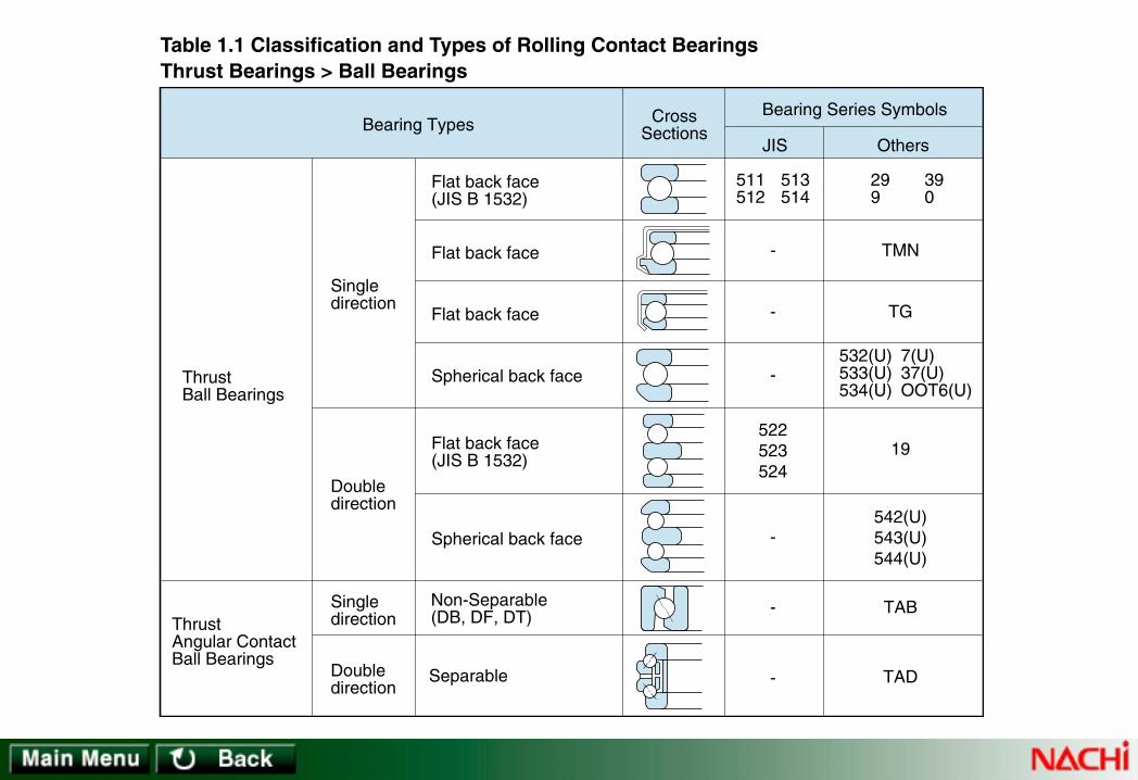
In general, rolling contact bearings may be classified as radial or thrust bearings according to bearing design or they may be classifiedas ball or roller bearings according to the type of rolling element.Radial bearings are mainly designed for supporting a load perpendicular to a shaft axis, whereas thrust bearings accept loads parallelto the shaft axis.Using the BALL and ROLLER classification ROLLER bearings may be further divided according to the shape of the roller into the sub-classes; Cylindrical roller, Tapered roller, Spherical roller, or Needle roller bearings. BALL bearings can be further divided according tothe number of rows into either single-row or double-row (for Thrust Ball bearings, single-direction and double-direction.) BALL Bearingmay be still further sub-divided into smaller segments according to the relationship between the bearing rings and rolling elements; theshape of bearing rings; and use of accessories.Bearings are also classified by specific application, such as Clutch-release ball bearings for automotive applications.Table 1.1 indicates the principal types of radial and thrust bearings and a summary of their design. Table 1.2 summarizes the designsand features of rolling contact bearings.
Table 1.1 Classification and Types of Rolling Contact Bearings
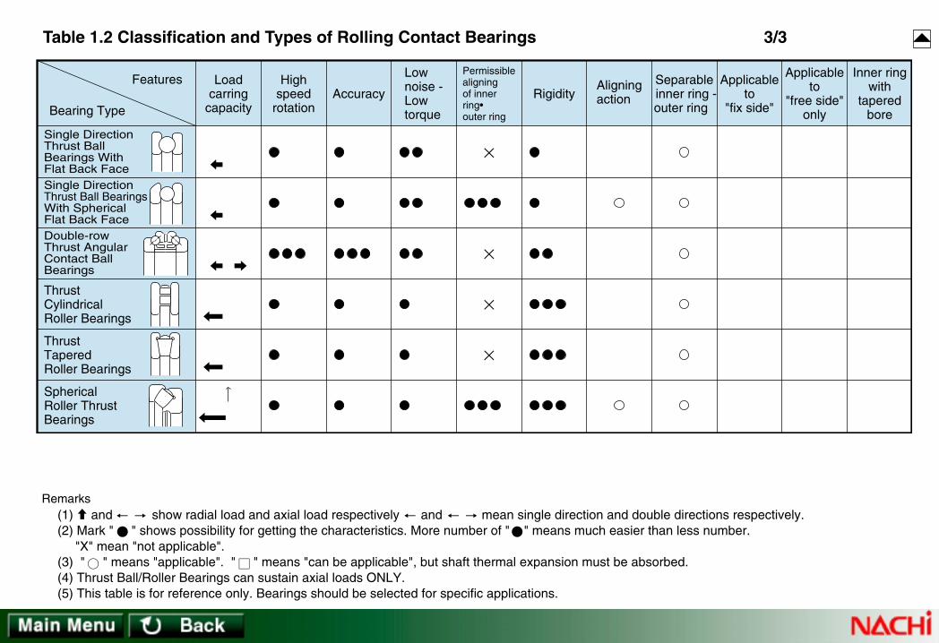
Table 1.2 Types and Features of Rolling Contact Bearings
Rolling Contact Bearings
Radial Bearings
Ball Bearings
Thrust Bearings Bearings for Specific Application
Roller BearingsBall Bearings Roller Bearings
1. T1. Types and Featurypes and Features of bearingses of bearings
1.1 Classification and T1.1 Classification and Types of Rolling Contact Bearingsypes of Rolling Contact Bearings

676869
606263
E EN
-
-
-
-
UB
KH
OOB60RLS RMS 16000
4243
BM
Bearing Types
Without filling slot(JIS B 1521)
Without filling slot [for unit ;JIS B 1558]
With filling slot
Without filling slot
With filling slot
Non-Separable
Separable (JIS B 1538)
JIS Others
Bearing Series SymbolsCrossSections
UCUWEUNE
UMUK
Counter-BoredBearings
Deep GrooveBall Bearings
Single row
Single row
Double row
Table 1.1 Classification and Types of Rolling Contact BearingsRadial Bearings > Ball Bearings
1/2

-
-
-
-
7970
1213
7273
2223
5253
3233
Singlerow
Doublerow
Doublerow
Duplexmounting
Withoutfilling slot
Withfilling slot
DB mountingDF mountingDT mounting
Separable
Non-Separable(JIS B 1522)
Outer ringraceway : spherical
Self-AligningBall Bearings
Angular ContactBall Bearings
Bearing TypesJIS Others
Bearing Series SymbolsCrossSections
Table 1.1 Classification and Types of Rolling Contact BearingsRadial Bearings > Ball Bearings
2/2

NF2NF3NF4
N2 N3 N4
NN30
N10
Singlerow
Doublerow
Cylindrical RollerBearings
NNU49
Inner ringwith a rib
Inner ring without rib
Inner ring without rib
Inner ringwith ribson both sides
Inner ringwith ribson both sides
Withoutloose rib
Withloose rib
Outer ringwith ribson both sides
Outer ringwith a rib
Outer ringwithout rib
Outer ringwithout rib
Outer ringwith ribson both sides
[JIS B 1533]
[JIS B 1533]
NJ2NJ22NJ3
NU10NU2NU22
NH2NH22NH3
NJ23NJ4
NU3NU23NU4
NH23NH4
Bearing TypesJIS Others
Bearing Series SymbolsCrossSections
Table 1.1 Classification and Types of Rolling Contact BearingsRadial Bearings > Roller Bearings
1/2

-
-
-
-
NA48NA49
RNA48RNA49
320302322
303303D323
329331313
330332
KBD
KBEKDE
239 230 240
231 241222
Outer ringwith ribs on both sides
232 213 223
Singlerow
Singlerow
Singlerow
Doublerow
Doublerow
Fourrow
Inner ring without rib
Withoutinner ring
Separable(JIS B 1534)
Outer ringraceway : spherical
Outer ringraceway : spherical
Separable
Separable(Inward)
Separable(Outward)
Tapered RollerBearings
Needle RollerBearings
Spherical RollerBearings
Bearing TypesJIS Others
Bearing Series SymbolsCrossSections
Table 1.1 Classification and Types of Rolling Contact BearingsRadial Bearings > Roller Bearings
2/2
Singledirection
Doubledirection
Flat back face(JIS B 1532)
Flat back face(JIS B 1532)
Spherical back face
Flat back face
Flat back face
Spherical back faceThrustBall Bearings
Singledirection
Doubledirection
Non-Separable(DB, DF, DT)
Separable
ThrustAngular ContactBall Bearings
511512
513514
522523524
-
-
-
-
-
-
299
390
TMN
TG
532(U)533(U)534(U)
7(U)37(U)OOT6(U)
19
542(U)543(U)544(U)
TAD
TAB
Bearing TypesJIS Others
Bearing Series SymbolsCrossSections
Table 1.1 Classification and Types of Rolling Contact BearingsThrust Bearings > Ball Bearings

Thrust CylindricalRoller Bearings
Thrust TaperedRoller Bearings
TMP
292293294
-
-
Singledirection
Flat back face
Flat back face
Singledirection
Spherical RollerThrust Bearings
Outer ringraceway : spherical
Bearing TypesJIS Others
Bearing Series SymbolsCrossSections
Table 1.1 Classification and Types of Rolling Contact BearingsThrust Bearings > Roller Bearings

-
-
-
Journal Bearings for Rolling Stocks
Sheave Bearings
-
-
-
-Self-AligningClutch-ReleaseBall Bearings
Ball Bearingsfor Air Conditioner Clutch
Ball Bearings for Wheel(1st type)
Ball Bearings for Wheel(2nd type)
Automotive Bearings
JT
FCDJCAP
E50RB48RC48
BG
F BVV
BVV
SCRN
Bearing TypesJIS Others
Bearing Series SymbolsCrossSections
Table 1.1 Classification and Types of Rolling Contact BearingsBearings for Specific Application

Table 1.2 Classification and Types of Rolling Contact Bearings 1/3
Deep GrooveBall Bearings
Angular ContactBall Bearings
Double RowAngular ContactBall Bearings
Duplex MountingAngular ContactBall Bearings
Self-AligningBall Bearing
CylindricalRoller Bearings
Double RowCylindricalRoller Bearings
Bearing Type
FeaturesAccuracy Rigidity
Aligningaction
Loadcarring
capacity
Highspeed
rotation
Applicableto
"fix side"
Applicableto
"free side"only
Inner ringwith
taperedbore
Separable inner ring •outer ring
Lownoise •Lowtorque
Permissiblealigningof innerring •outer ring
Remarks (1) and show radial load and axial load respectively and mean single direction and double directions respectively. (2) Mark " " shows possibility for getting the characteristics. More number of " " means much easier than less number. "X" mean "not applicable". (3) " " means "applicable". " " means "can be applicable", but shaft thermal expansion must be absorbed. (4) Thrust Ball/Roller Bearings can sustain axial loads ONLY. (5) This table is for reference only. Bearings should be selected for specific applications.

Table 1.2 Classification and Types of Rolling Contact Bearings 2/3
CylindricalRoller BearingsWith One RibInner RingCylindricalRoller BearingsWith L-shapedThrust Collar
NeedleRoller Bearings
Bearing Type
FeaturesAccuracy Rigidity
Aligningaction
Loadcarring
capacity
Highspeed
rotation
Applicableto
"fix side"
Applicableto
"free side"only
Inner ringwith
taperedbore
Separable inner ring •outer ring
Lownoise •Lowtorque
Permissiblealigningof innerring •outer ring
Double-rowMulti-rowTaperedRoller Bearings
TaperedRoller Bearings
SphericalRoller Bearings
Remarks (1) and show radial load and axial load respectively and mean single direction and double directions respectively. (2) Mark " " shows possibility for getting the characteristics. More number of " " means much easier than less number. "X" mean "not applicable". (3) " " means "applicable". " " means "can be applicable", but shaft thermal expansion must be absorbed. (4) Thrust Ball/Roller Bearings can sustain axial loads ONLY. (5) This table is for reference only. Bearings should be selected for specific applications.
Bearing Type
FeaturesAccuracy Rigidity
Aligningaction
Loadcarring
capacity
Highspeed
rotation
Applicableto
"fix side"
Applicableto
"free side"only
Inner ringwith
taperedbore
Separable inner ring - outer ring
Lownoise -Lowtorque
Permissiblealigningof innerring•outer ring
Single DirectionThrust BallBearings WithFlat Back FaceSingle DirectionThrust Ball BearingsWith SphericalFlat Back FaceDouble-rowThrust AngularContact BallBearings
ThrustCylindricalRoller Bearings
ThrustTaperedRoller Bearings
SphericalRoller ThrustBearings
Table 1.2 Classification and Types of Rolling Contact Bearings 3/3
Remarks (1) and show radial load and axial load respectively and mean single direction and double directions respectively. (2) Mark " " shows possibility for getting the characteristics. More number of " " means much easier than less number. "X" mean "not applicable". (3) " " means "applicable". " " means "can be applicable", but shaft thermal expansion must be absorbed. (4) Thrust Ball/Roller Bearings can sustain axial loads ONLY. (5) This table is for reference only. Bearings should be selected for specific applications.

Rolling Contact Bearings usually consist of an inner ring, outer ring, and rolling elements (balls or rollers), and a cage which positionsthe rolling elements at fixed intervals between the ring raceways. (See Figure 1 ).Standard materials for inner and outer rings, and for the rolling elements, are high carbon chromium bearing steel or case hardeningsteel. The steel is heat-treated to an appropriate hardness to attain optimum resistance to rolling fatigue. Bearing surfaces are groundto a very high accuracy using special machine tools.While each of the various types of rolling contact bearings has special features, the following features are common to most rollingcontact bearing types:• Rolling contact bearings have relatively low starting resistance. There is little difference between the starting and running resistanceof rolling contact bearings.
• Dimensions and accuracy are standardized. Ready-made products of high quality are easy to obtain.• Compared to “sliding” bearings, rolling contact bearings are less prone to wear and help to maintain the accuracy of the machine inwhich they are used.
• Rolling contact bearings consume small amounts of lubricant and are far less costly to maintain than sliding-type bearings.• While not common to all rolling contact bearings, many types can sustain both axial and radial loads.To get optimum performance from a selected bearing, it is necessary to understand the design and features of the various bearingtypes and to then select bearings optimal to individual machine performance.
Deep Groove Ball Bearing
Outer ring
Inner ring
Cage
Ball Rolling element
Tapered Roller Bearing
Cup
Cone
Cage
Roller
Fig 1. Rolling Contact Bearing Designes
1.2 Rolling Contact Bearing Designs and Featur1.2 Rolling Contact Bearing Designs and Featureses

1.2.2 Single-r1.2.2 Single-row Angular Contact Ball Bearingsow Angular Contact Ball Bearings
The raceways of both the inner and outer rings of this bearing type are made with a set contact angle. Thesebearings are non-separable. Since the balls are inserted utilizing counter-bore construction, a larger number ofballs can be installed than in the case of Deep-groove ball bearings.Standard cage materials may be pressed steel, high-strength brass, or synthetic resin. Cage material isdependent on the bearing series and or service condition.Single-row Angular Contact ball bearings can sustain radial, axial or composite loads, however, any axial loadmust be in one direction.This bearing type is generally used in pairs to handle the induced load resulting fromthe internal axial force generated by the applied radial load. When mounting twosingle bearings in adjacent positions, NACHI provides these combination parts(pairs) with preadjusted clearance. Paired combination bearings are matched sets.Combination or paired bearings can be arranged BACK-TO-BACK (DB), FACE-TO-FACE (DF), or in TANDEM (DT). DB or DF sets can sustain bidirectional axial loads.
DB(Back-to-back)
DF(Face-to-face)
DT(Tandem)
1.2.1 Deep Gr1.2.1 Deep Groove Ball Bearingsoove Ball Bearings
Deep Groove ball bearings are the most popular of all the ball bearing types because they are available in a widevariety of seal, shield and snap-ring arrangements.The bearing ring grooves are circular arcs made slightly larger than the radius of the ball. The balls make pointcontact with the raceways (elliptical contact when loaded). The inner ring shoulders are of equal height (as theouter ring shoulders).Deep Groove ball bearings can sustain radial, axial, or composite loads and because of simple design, thisbearing type can be produced to provide both high-running accuracy and high-speed operation.Deep Groove ball bearings having an outside diameter less than 9 mm are known as Miniature ball bearings.Deep Groove ball bearings having an outside diameter => 9 mm and a bore diameter < 10 mm are known asExtra-small ball bearings.Standard ball retainers (cages) are made from pressed steel. Machined cages are used in bearing operating atvery high speed or for large diameter bearings.Deep groove ball bearings with seals or shields are standardized. They contain proper amount of grease inadvance.

1.2.4 Self-aligning Ball Bearings1.2.4 Self-aligning Ball Bearings
This type is constructed with the inner ring and ball assembly contained within an outerring which has a spherical raceway. Due to the construction, this bearing type willtolerate a small angular misalignment from deflection or mounting error.Self-aligning Ball bearings are suitable for long shafts where accurate positioning ofhousing bores is difficult. This type is often used in conjunction with pillow blocks.Cages are made from pressed steel or polyamide resin.This bearing should only be used in light axial load applications due to the small axialsupport of the rolling elements by the outer ring raceway.
1.2.3 Double-r1.2.3 Double-row Angular Contact Ball Bearingsow Angular Contact Ball Bearings
The construction of this type ball bearing is similar to the adjacent, BACK-TO-BACK mounting of two Single-rowAngular Contact ball bearings. Because fewer balls can be inserted per row compared to Single-row AngularContact ball bearings, a Double-row Angular Contact ball bearing will have less load capacity than an equivalentsize/series BACK-TO-BACK set of two Single-row Angular Contact ball bearings.This bearing type can sustain radial, moment and bi-directional axial loads.
α
[Continue→]
1.2.5 Cylindrical Roller Bearings1.2.5 Cylindrical Roller Bearings
Construction of this roller bearing type is the simplest of all radial roller bearings. This bearing type is often used in high-speedapplications.Because the inner ring, outer ring, and rollers are in line contact, this bearing type has a large radial load capacity. Various Cylindricalroller bearing configurations are:N,NJ,NF,NU,RNU : integral ribs (flanges)NH,NP,NUP,NUH : integral and loose ribsNN,NNU : double-row bearings

1.2.6 T1.2.6 Taperapered Roller Bearingsed Roller Bearings
The inner and outer ring raceways and rollers of this type of bearing are made with a taper so that the planes ofthe surfaces of the raceways and roller axis meet at a point. The rollers are guided by the cone (inner ring) back-face rib.A single-row Tapered roller bearing can support a combined radial and axial load. If either a radial load orbi-directional axial load is to be carried, a pair of bearings must be used in a “face-to-face” or “back-to-back”position.Tapered roller bearings are separable into the components: outer ring, inner ring and roller assembly. The non-separable inner ring and roller assembly is called the “cone”, and the outer ring is called the “cup”. Internalclearance is established during mounting by the axial positioning of the cone relative to the cup.This bearing type can be used in a preload situation to obtain higher rigidity and better running accuracy of theshaft. Double-row and four-row Tapered roller bearings are designed to carry radial, and bi-directionalaxial loads. Four-row Tapered roller bearings are used for the roll necks of rolling machines and forother applications where heavy or impact loads are present.Multi-row Tapered roller bearings have the serial number and the combination symbol stamped onthe faces of the rings for clearance adjustment and must be assembled according to this numberand symbol.Pressed steel cages are used for small bore bearings and machined, high-strength brass or mild-steel cages are used for bearings with larger bores. Heavy-duty pin-type cages are used for somelarge-bore bearings.
(See the Cylindrical roller bearing dimensional data section for description of configurationdesign).Configurations having integral flanges or loose ribs on both the inner and outer rings can sustaina small amount of axial load. Since this bearing type supports axial loads as sliding actionbetween the end of the rollers and flange faces, axial loading is limited.Double-row Cylindrical roller bearings are used for high-speed, high-accuracy applications suchas; main spindle support for lathes, milling machines, and machining centers. Radial clearance oftapered-bore bearings can be adjusted during mounting of the bearing(s) onto the mating journal.Standard cages are pressed steel or polyamide resin. Machined cages of high-strength brass areused for bearings of large dimension or for high-speed applications.
[→Continue]
2α

α
1.2.8 Thr1.2.8 Thrust Ball Bearingsust Ball Bearings
Thrust ball bearings can handle axial loads only. Bearing rings mounted on the shaft are called shaft washers,and those mounted in the bearing housing are called housing washers. Both washers contain grooves for theballs.Thrust Ball bearings are of two types: single type which can support axial loads in only one direction and doubletype that can support bi-directional loads. The central washer of double type thrust ball bearing is located in anaxial direction by a shaft shoulder and sleeve.Thrust Ball bearings are not suitable for high-speed rotation since lubricant is expelled by centrifugal force.When used on a horizontal shaft, a minimum axial load must be applied.Pressed steel plate, polyamide resin, machined high-strength brass or mild steel are used for cages.Care must be taken in handling to prevent damage to the separable rings and ball assembly.
1.2.7 Spherical Roller Bearings1.2.7 Spherical Roller Bearings
NACHI double-row Spherical roller bearings are available in bore sizes from 25 mm to over 1000 mm.The raceways in the outer ring of this type bearing are designed with a spherical surface whose centercoincides with the bearing center.NACHI Spherical roller bearings are of an improved design having a modified line contact between theraceways and rollers. This construction enables very high radial and impact-load capacity.This bearing type can carry a moderately-high level of bi-directional axial load and is self-aligning. This type isused extensively for large machines where shaft deflection or mounting error may occur.Spherical roller bearings are used for paper mill equipment, rolling machines, rolling stock, shaker screens andgeneral industrial machinery. The mounting and dismounting of Spherical roller bearings is facilitated throughthe use of tapered-bore bearings in conjunction with tapered journals, or adapters or withdrawal sleeves.Internal clearance can also be precisely set using a tapered-bore bearing.Pressed steel cages are used for small-bore bearings and machined, high-strength brass or mild-steel cagesare used for bearings with larger bores.
1.2.9 Spherical Roller Thr1.2.9 Spherical Roller Thrust Bearingsust Bearings
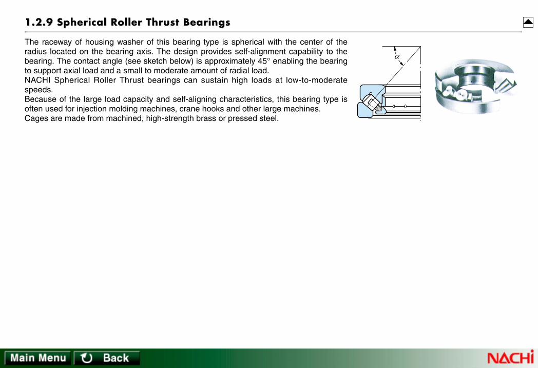
The raceway of housing washer of this bearing type is spherical with the center of theradius located on the bearing axis. The design provides self-alignment capability to thebearing. The contact angle (see sketch below) is approximately 45° enabling the bearingto support axial load and a small to moderate amount of radial load.NACHI Spherical Roller Thrust bearings can sustain high loads at low-to-moderatespeeds.Because of the large load capacity and self-aligning characteristics, this bearing type isoften used for injection molding machines, crane hooks and other large machines.Cages are made from machined, high-strength brass or pressed steel.
α

IntrIntroductionoduction
2.1 Bearing T2.1 Bearing Type Selection Considerationsype Selection Considerations
2.1.1 Load2.1.1 Load
2.1.2 Rotating Speed2.1.2 Rotating Speed
2.1.3 Noise and T2.1.3 Noise and Tororqueque
2.1.4 Alignment2.1.4 Alignment
2.1.5 Rigidity2.1.5 Rigidity
2.1.6 Mounting, Dismounting2.1.6 Mounting, Dismounting
2.1.7 Axial Location; Bearing Ar2.1.7 Axial Location; Bearing Arrangementrangement
2.1.8 Bearing Envir2.1.8 Bearing Environmentonment
2. Selection of Bearings2. Selection of Bearings

Rolling contact bearings are important, often critical, components of machinery. To meet the demands of a large variety ofapplications, rolling contact bearings are manufactured in a wide variety of types, sizes, and configurations. While machineperformance and service life depend on which bearings are selected, it is often difficult to select the optimal bearing fromamong the many available variations.While there is no "best" procedure for selecting the optimal bearing, Figure 2.1 provides an example of a procedure based onthe establishment of priorities for the required bearing characteristics.
Load (direction, size, oscillation, shock) Rotating speedSound & torqueMisalignment RigidityAxial positioningMounting & dismountingEnvironment (vibration, shock)
Space for bearingsDesired service lifeRotating speedStandard parts available
Determine which ring rotatingProperties & size of loadHousing & shaft construction, materialAmbient temperature
Decision
Final decision
Examine bearingtype and sizes
Decision
Examine bearingdimensions
Decision
Examine accuracy
Decision
Examine shaft& housing fits
Deflection of rotating ringVibration from rotationRotating speedTorque & torque fluctuation
Decision
Decision
Decision
Decision
Dimensions for assembly clearances,Procedures for assembly, dismountingParts accessories for mounting
Clearance reduction by fitsMisalignmentTemperature difference between ringsPreloads
Rotating speedSound & vibrationTorque fluctuation
Operating temperatureRotating speedLubricant and delivery systemSpecial atmospheric (water, chemicals)Construction & material of seal device
Operating temperatureAtmospheric conditions (corrosives)Impact, vibratory load conditions
Bearing performancerequirements,serviceconditions & environment
Examine internalclearance
Examine cage type& material
Examine lubrication& sealing
Examine ring,rolling element material
Examine installation& maintenance
2. Selection of Rolling Contact Bearings2. Selection of Rolling Contact Bearings
Fig. 2.1 Bearing Selection Procedure

2.1.1 Load2.1.1 Load
Bearing types are selected according to the types of load (radial, axial, moment) and the magnitude of these loads on the bearing.Table 2.1 outlines the types of load and applicable bearing types. In bearings of identical dimensional series, a roller bearing will havea greater load rating capacity than a ball bearing.
2.1 Bearing T2.1 Bearing Type Selection Considerationsype Selection Considerations
Single-row Deep Groove
Single-row Angular Contact
Paired Angular Contact
Double-row Angular Contact
Cylindrical
Single-row Tapered
Paired Tapered
Multi-row Tapered
Spherical radial
Spherical thrust
Ball bearings:
Roller bearings:
RadialAxialMoment
Load type
Bearing type
Remarks: Bearing type can meet the load type. Bearing can meet the load type conditionally. (Contact NACHI for more information.)
Table 2.1 Applicable Bearings vs Load Type

2.1.4 Alignment2.1.4 Alignment
If the accuracy of alignment of the shaft and bearing housingis poor or the shaft is deflected due to load, the inner andouter rings of the bearings will be misaligned.Non-self-aligning rolling contact bearings are capable oftolerating only that amount of misalignment which can behandled by the assembled internal clearance. If inclination isexpected to occur between the inner and outer rings, thechoice of bearings should be from types such as thrust ballbearings with self-aligning washer, Self-aligning ballbearings, or Spherical roller bearings.The permissible angle of inclination of bearings differs bybearing type, internal clearance, and load conditions. Table2.2 outlines the permissible angles of mis-alignment bybearing type.Internal bearing damage can occur if misalignment in thebearing is greater than the permissible angle. Please contactNACHI for assistance.
2.1.3 Noise and T2.1.3 Noise and Tororqueque
All NACHI rolling contact bearings are designed and manufactured to operate with low noise and torque levels. Of the many types ofball and roller bearings, single-row deep-groove ball bearings will tend to operate with the lowest noise and torque levels.
2.1.2 Rotating Speed2.1.2 Rotating Speed
Limiting speed of bearings is determined by bearing type, bearing dimensions, accuracy of work, construction of cages, load,lubricating system, and seal type and design. The bearing dimension tables show the rotating speed limits of standard rolling contactbearings as a criterion of bearing type selection.Bearings used at high rotating speeds should generally have high accuracy. In applications over the limiting speed, please consultNACHI for assistance.
Single-row deep groove ball bearings
Single-row angular contact ball bearings
Cylindrical roller bearings
Tapered roller bearings
Thrust ball bearings
1/300
1/1000
1/1000
1/800
1/2000
Bearing typePermissible angle of
misalignment
Table 2.2 Permissible Misalignment of Bearing Types

2.1.7 Axial Location; Bearing Ar2.1.7 Axial Location; Bearing Arrangementrangement
Generally the shaft is supported by two units (or the equivalent to two units) of bearings. Generally, one of the bearings acts to hold (orfix) the axial position of the assembly and the other bearing acts to allow linear expansion.The fixed side bearings must be firmly seated against both housing and shaft.Table 2.3 shows representative examples of actual bearing arrangements according to service conditions.
2.1.8 Bearing Envir2.1.8 Bearing Environmentonment
If there is a comparatively large source of vibration near the bearing mount, or if the bearing is to handle impact loading, the use ofSpherical roller bearings or Spherical roller thrust bearings is recommended.Standard bearings will be not suitable to be operated under severe condition (load, rotating speed, operating temperature, lubricationamount, vibrating environment).
2.1.5 Rigidity2.1.5 Rigidity
When rolling contact bearings are loaded, the contact section between the bearing rings and rolling elements will elastically deform.The magnitude of this elastic deformation will differ depending on load, bearing type, and bearing dimensions.If bearings of identical dimension series are compared, roller bearings will have a much higher level of rigidity than ball bearings, and ifbearings of identical type are compared, bearings of larger dimensions will have higher rigidity than those of smaller dimensions. (Pre-loading combinations of units of two or more bearings will increase rigidity.)
2.1.6 Mounting, Dismounting2.1.6 Mounting, Dismounting
Rolling contact bearings can be divided into bearing types classed as separable or non-separable. Mounting and dismounting isfacilitated if a separable bearing type is used.Use of tapered-bore bearings and sleeves or hydraulic assist also makes bearing mounting and dismounting easier.There is a possibility that noise and shortening of life occur due to poor mounting of bearings. When bearings are mounted, thefollowing items should be noticed.-Keep the bearings clean-Rust prevention-Protect bearings from external damage
Table 2.3 Examples of Bearing Arrangements

Table 2.3 Examples of Bearing Arrangements
Mounting examplesNo. Application & design considerationsApplicable bearingsA B
Deep Groove Ball
Spherical Roller
CylindricalRoller; N, NUconfiguration
CylindricalRoller; NHconfiguration
CylindricalRoller; N, NUconfiguration
Spherical Roller
Deep Groove Ball
Deep Groove Ball
Popular mounting. Ball bearings can support light-to-moderate axial loads.Spherical roller bearings are good for heavy radial loads and light axial loads.One of the bearing outer ring must be free to move axially to handle thermal expansion.
Popular mounting. Axial expansion of shaft taken by inner ring of Cylindrical roller bearing.Use a Cylindrical roller bearing for the heavy load position.The Deep groove ball bearing carries the axial load.Not recommended for handling angular misalignment.
Easy mounting arrangement where interference fit is required for both inner and outer rings.Not recommended for handling angular misalignment.Thermal expansion taken internally.Suitable for light axial load applications.
A B
A B
A B
1
2
3
1/4

Mounting examplesNo. Application & design considerationsApplicable bearingsA B
Spherical Roller Spherical Roller
Self-AligningBall
Self-AligningBall
Double-RowAngularContact Ball
Double-RowAngularContact Ball
CylindricalRoller; N, NUconfiguration
Deep Groove Ball
Good for moderate, bidirectional axial loads.When using Deep groove ball bearings in position <A>, and double-row bearings in position <B>, the outer ring of one of the parts must be free to move axially for thermal expansion. If an N, or NU configuration bearing is used in position <A>, thermal expansion can be taken internally and a much greater radial load can taken on side <A>.A B
Good for small angular misalignment.Use with adapter for long shafts which eliminates costly, shaft-weakening shaft shoulders and threading.Outer ring of one bearing must be free to move to compensate for thermal expansion or mouting error.Axial load capacity is light for ball bearing and moderate for Spherical roller bearing.Check with NACHI if Fa/Fr ratio is greater than 0.6 for Spherical roller bearings.
A B
AngularContact Ball
AngularContact Ball
Deep Groove Ball Deep Groove Ball Preloading allows good rigidity.Care must be taken in design of preload amount.Angular contact ball bearings are better than Deep groove ball bearings for moderate axial laods and preload.
A B
4
5
6
Table 2.3 Examples of Bearing Arrangements 2/4

A B
Good for heavy loads and radial and axial rigidity.Clearance on side <A> easy to adjust. Thermal expansion can be taken by Cylindrical roller bearing.Alignment must be accurate.
Mounting examplesNo. Application & design considerationsApplicable bearingsA B
Tapered RollerCylindricalRoller; N, NUconfiguration
AngularContact Ball
AngularContact Ball
General application, direct mounting ("face-to-face").Good for heavy axial loads.Clearance easily adjustable.Assembly is convenient where one or both inner ring are interference-fit to shaft.
Indirect mounting ("back-to-back").Good shaft rigidity.Good for moment loading.Good for large axial and radial loads.Use care in establishing preload or clearance.
A B
A B
Tapered Roller Tapered Roller
Tapered Roller Tapered Roller
7
8
9
Table 2.3 Examples of Bearing Arrangements 3/4

Good for very accurate rotation and light loads.Two bearings are used in pairs with preload.Good shaft rigidity.Alignment must be accurate.Mounting example above the shaft center line is DB ("back-to-back") mount; below line is DT ("tandem") mount.
Thrust bearing should be close to radial bearing to reduce shaft deflection.When using Thrust ball bearing on a horizontal shaft, it is important to keep a load on the thrust bearing at all times.If there is shaft deflection at the thrust bearing location, use of a Thrust ball bearing with aligning washer arrangement is recommended.
Spherical roller thrust bearings are applicable if radial load is 55% or less than that of axial load.Suitable for heavy axial load.Good where there is shaft deflection and housing accuracy error.Axial load must be continuous.Used in conjunction with radial bearings at low-to-moderate speed.
A DT B
DB
Mounting examplesNo. Application & design considerationsApplicable bearingsA B
CylindricalRoller
CylindricalRoller
Paired AngularContact Ball
Paired AngularContact Ball
Deep GrooveBall & ThrustBall
CylindricalRoller & ThrustBall
SphericalRoller Thrust
Various RadialTypes
10
11
12
Table 2.3 Examples of Bearing Arrangements 4/4

3.1 Basic Dynamic Load Rating and Rating Life3.1 Basic Dynamic Load Rating and Rating Life
3.2 Basic Rating Life Calculation Guide3.2 Basic Rating Life Calculation Guide
3.3 Rating Life and Operating T3.3 Rating Life and Operating Temperaturemperaturee
3.4 Calculation of Bearings Load3.4 Calculation of Bearings Load
3.5 Dynamic Equivalent Load3.5 Dynamic Equivalent Load
3.6 Basic Static Load Rating and Static Equivalent Load3.6 Basic Static Load Rating and Static Equivalent Load
3.7 Axial Load Capacity of Cylindrical Roller Bearings3.7 Axial Load Capacity of Cylindrical Roller Bearings
3. Load Capacity and Life of Bearings3. Load Capacity and Life of Bearings

3.1 Basic Dynamic Load Rating and Rating Life3.1 Basic Dynamic Load Rating and Rating Life
Although requirements of rolling contact bearings vary somewhat with the individual application the principal requirements are:• High load capabilities• Smooth and quiet rotation• High rigidity• Low friction• High accuracy• Reliability
The reliability or durability requirement sets the time frame over which all other requirements are to be maintained. The reliabilityrequirement (life in the broad sense) includes grease and acoustic life, as well as fatigue life. Reliability is reduced by various types ofdamage and degradation.Improper handling, mounting, lubrication, and fits are the major causes of problems leading to lower-than-calculated bearing life.Regardless of how well they are maintained or mounted or handled, dynamic bearings will eventually fail from rolling fatigue generatedby the repetitive stress of bearing load.The service life of a bearing can be examined from two perspectives: 1)If, from inspection, a trace of fatigue becomes noticeable, thebearing should be deemed not suitable for further use; or 2) length of bearing life in hours or revolutions can be predefined as a limitbeyond which the bearing is automatically replaced. Since calculated fatigue life will vary with the size and type of bearings used under identical load conditions, great care must be takenin the analysis of the load conditions and the final choice of bearings to satisfy the application requirements.Fatigue lives of individual bearing are dispersed. When a group of identical bearings operate under the same conditions, the statisticalphenomenon of dispersion will appear. Use of average life is not an adequate criterion for selecting rolling contact bearings. Instead, itis more appropriate to consider a limit (hours or numbers of revolutions) which a large percentage of the operating bearings can attain.Accordingly, the rating life and basic dynamic load rating Cr or Ca are defined using the following definition:• Basic rating life is defined as the total number of revolutions (or total operating hours at some given constant speed) that 90% of agroup of identical bearings operated individually under equal conditions can complete without suffering material damage from rollingfatigue.
• Basic dynamic load rating (Cr or Ca) is defined as a bearing load of constant direction and size that ends the bearing life after amillion revolutions.
3. Load Capacity and Life of Rolling Contact Bearings3. Load Capacity and Life of Rolling Contact Bearings
[Continue→]

L
L
CP
h CP n
p
p
= ( )
= ( ) ⋅
1060
6
• • • • • • (3.1)
• • • • • • (3.2)
The relationship of fh, the bearing life factor and fn, thespeed factor, is outlined in Table 3.1.Formula (3.3) may be used to determine the basic dynamicload rating, C, of bearings given the bearing equivalent load,P, and the operating speed, n, in revolutions-per-minute.The lives of automobile wheel bearings may be defined inkilometers using the formula (3.4).Table 3.2 shows values for the life factor, fh, by applicationand machine type.If a bearing is used with vibrating or impact loads or lowspeed including no rotation, additional study with basic staticload rating is required.
Where:L : Basic rating life (106 rev.)
Lh : Basic rating life in hoursC : Basic dynamic load rating (N). (Cr for radial bearings and Ca
for thrust bearings)P : Bearing load (dynamic equivalent load) (N) Pr for radial, and,
Pa for thrust bearingsp : 3 for ball, 10/3 for roller bearingsn : Rotating speed (rpm)
Ball Bearings Roller Bearings
Basic Rating Life
Life Factor
Speed Factor
L fh h= 500 3L fh h= 500
103
f fn CP
h = f fn CP
h =
fn
n =×
10500 60
613
fn
n =×
10500 60
63
10
Table 3.1 Bearing Basic Rating Life; Life and Speed Factors
C Pfn
hL p
= ( )500
1• • • • • • (3.3) Where:
Ls : Kilometer traveled (106 km)D : Outside diameter of wheel (m)L : Life in revolutionsLs D L= ⋅ ⋅π
1000• • • • • • (3.4)
Table 3.2 Life Factors (fh)
Constant-direction radial or thrust loads (for radial and thrust bearings, respectively) are used as the basis of the ratings.The rating life of bearings is calculated by formulas (3.1) and (3.2):

Hand toolsAgricultural equipmentHousehold apparatusCasting plant cranes
Power plant auxiliary machinesAssembly line conveyersGeneral crane applicationsMotors for home air conditioning
General gearing applicationsGeneral industrial motors
Cranes in continuous useAir blowersMechanical power transmissionGeneral industrial machineryIndustrdal wood-working machines
CompressorsMine hoistsMarine propeller shaftsRolling machine tables
Paper manufacturingPower plantsWater supply equipmentMine water pumps, air blowers
Short period or Intermittent use
Intermittent, critical use
8 hour per day, intermittent
24 hour per, critical
Infrequent use
8 hour per day, continuous
24 hour per day, continuous
Application conditions Application example Life Factor (fh)
Hinges to 1.5
2 ~ 3
3 ~ 4
3 ~ 5
4 ~ 5
5 ~ 8
6-up
Table 3.2 Life Factors (fh)

3.2 Basic Rating Life Calculation Guide3.2 Basic Rating Life Calculation Guide• Determine the bearing life normal to the application by using Table 3.2 to define the life factor, fh.• Use rating life charts (nomograms) to calculate life. The nomogram for ball bearings is shown in Fig. 3.4. The nomogram for roller
bearings is shown in Fig. 3.5. These nomograms are based on formulas (3.1) and (3.2).• Where operating temperatures are to be in excess of 150°c, a correction factor must be applied to the bearing basic dynamic load
rating. (See Item 3.3.1).• If the bearings are to operate with vibration or impact loading, or where a bearing mounting or manufacturing error exists, the actual
load may be greater than the calculated load. In this case, the calculated load must be multiplied by a safety coefficient to obtain anapproximation of the actual load. For safety coefficients in actual application, refer to the machine and drive factors. (See Item 3.4.1and 3.4.2)
• Bearings do not always operate under a constant load. When the bearing operates with a fluctuation load, the load must beconverted to a constant size reflecting the effect of the fluctuating load. Conversion may be done using weighted average meanloading (See Item 3.4.4).
• By definition, bearing load Pr (net radial load) or Pa (net axial load) is a load with constant direction and size. When a composite loadof radial and axial loads occurs on a radial bearing, these loads must be converted to a radial load reflecting the effect of thecomposite load. This effective load is called the DYNAMIC EQUIVALENT LOAD. (See Item 3.5).
• When calculating bearing load using the loads on a position on the shaft, it is necessary to calculate center distance between theload application point of the bearings. Many bearing types have load center points at the center line of the width as shown in Fig.3.1. Single-row Angular Contact ball bearings and single-row Tapered roller bearings, have load center points off-center to the centerline of the bearing width (See Fig. 3.2 and 3.3 respectively). Refer to the dimension tables for the value of the off-set.
• The axial load limit for Cylindrical roller bearings is a function of the lubrication conditions and speed of rotation. This limit differs froma rating load as determined by fatigue life. (See Item 3.7).
Fig 3.1
Applied Load Centers
Fig 3.2
Applied Load Centers
Fig 3.3
Applied Load Centers
[Continue→]

Calculation example : 1Suppose that an application has selection parameters as follows :Bore : 50 mm or smallerOutside diameter : 100 mm or smallerWidth : 20 mm or smallerRadial load (Fr) : 4000 N (Newtons)Rotating speed (n) : 1800rpmLife factor (fh) : 2 or greaterBearing type : Single-row deep groove ball bearing
From Table 3.1 the speed factor, fn is obtained as follows:
From Table 3.1,
6209 45 85 19 32500
6307 35 80 21 33500
Bearing No.BoreDia.(mm)
OutsideDia.(mm)
Width(mm)
BasicDynamic
Load Rating(N)
Bearings having the required basic dynamic load rating areselected from the bearing dimension table(s). Of the two sizesmeeting the load and diameter constraints, only bearing 6209 willsatisfy the width constraint. Given the above parameters, bearingpart 6209 would be the selection.
fn =× ×
=10
500 60 18000 265
613
.
C ff
r h Pn
N= ⋅ = × =2 40000 265
30188.
[→Continue]

500
1000
5000
10000
50000
100000
500000
1000000
10050 100 500 1000 5000 10000 50000 100000
1.001.12
1.251.40
1.601.80
2.002.24
2.502.80
3.153.55
4.004.50
7.108.00
9.0010.00
11.2 12.5
14.0 16.0
18.0 20.0
22.4 25.0
28.0 31.5
35.5 40.0
45.0 50.0
56.0 63.0
71.0 80.0
90.0
5.005.60
6.30
1090959999.599.9
100
500
1000
5000
10000
50000
100000
500000
C/P=
C/P=100
Ball Bearing
Operating speed rpmReliability %
Life
hou
rs h
Fig 3.4 Ball Bearing Reliability Nomogram
Calculation example: 2

1 1.12
1.251.4
1.6 1.8
2 2.24
2.5 2.8
3.153.55
7.1 8
9 10
11.2 12.5
14 16
18 20
22.4 25
5 5.6
6.3
C/P=
4 4.5 C/P=5
28
C/P= 31.5
Roller BearingFig 3.5Roller BearingReliability Nomogram
Life
hou
rs h
Operating speed rpmReliability %
50 100 500 1000 5000 100001090
959999.599.9
100
500
1000
5000
10000
50000
500000
500
1000
5000
10000
50000
100000
500000
1000000
100
100000
Calculation example: 3

Calculation example: 2Bearing Number 6012 is loaded with an dynamic equivalent radial load Pr = 2950N.Object is to obtain the life at various levels of reliability when the bearing is rotated at n = 800 rpm.The basic dynamic load rating Cr is taken form the dimension table.
Cr = 29400NCr/Pr = 10
( * ) For reliabilities, see Item 3. 3. 2.
By tracing the dotted lines, rating lives are obtained as follows:Reliability (*) Life hours90% 2000095% 1500099% 450099.9% 1200
Calculation example: 3Bearing Number 22222EX is loaded with dynamic equivalent radial load Pr = 98000N.Object is to obtain the life at various levels of reliability when the bearing is rotated at n = 500 rpm.The basic dynamic load rating Cr is taken from the dimension table.
Cr = 490000NCr/Pr = 5
By tracing the dotted lines, rating lives are obtained as follows:Reliability (*) Life hours90% 700095% 440099% 150099.9% 400
(*) For reliabilities, see Item 3. 3. 2.
Fig 3.5 Roller Bearing Reliability Nomogram
Fig 3.4 Ball Bearing Reliability Nomogram
3.3.1 T3.3.1 Temperaturemperature-Related Decre-Related Decrease in Basic Dynamic Load Ratingease in Basic Dynamic Load Rating
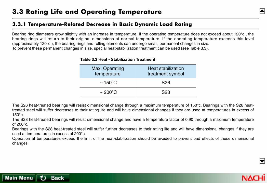
Bearing ring diameters grow slightly with an increase in temperature. If the operating temperature does not exceed about 120°c , thebearing rings will return to their original dimensions at normal temperature. If the operating temperature exceeds this level(approximately 120°c ), the bearing rings and rolling elements can undergo small, permanent changes in size.To prevent these permanent changes in size, special heat-stabilization treatment can be used (see Table 3.3).
The S26 heat-treated bearings will resist dimensional change through a maximum temperature of 150°c. Bearings with the S26 heat-treated steel will suffer decreases to their rating life and will have dimensional changes if they are used at temperatures in excess of150°c.The S28 heat-treated bearings will resist dimensional change and have a temperature factor of 0.90 through a maximum temperatureof 200°c.Bearings with the S28 heat-treated steel will suffer further decreases to their rating life and will have dimensional changes if they areused at temperatures in excess of 200°c. Operation at temperatures exceed the limit of the heat-stabilization should be avoided to prevent bad effects of these dimensionalchanges.
3.3 Rating Life and Operating T3.3 Rating Life and Operating Temperaturemperaturee
Max. Operatingtemperature
~ 150ºC
~ 200ºC
Heat stabilizationtreatment symbol
S26
S28
Table 3.3 Heat - Stabilization Treatment

~ 150ºC 175ºC 200ºC
1
Bearing Temperature
Temperature Factor 0.95 0.90
Table 3.4 Temperature Factor
If bearings are operated at temperatures exceeding the limit of the heat-stabilization, hardness of the bearing steel will be reduced. Incalculating the life of such bearings, the basic dynamic load rating must be multiplied by the temperature factor as shown in Table 3.4.The temperature factor for standard bearings operating at a temperature under 120°c is 1 and these bearings will show nodimensional change. Standard bearings run at an operating temperature exceeding 120°c, will experience dimensional changes andare subject to the basic dynamic load rating decreases as shown in Table 3.4.
3.3.2 Life Calculation Factors3.3.2 Life Calculation Factors
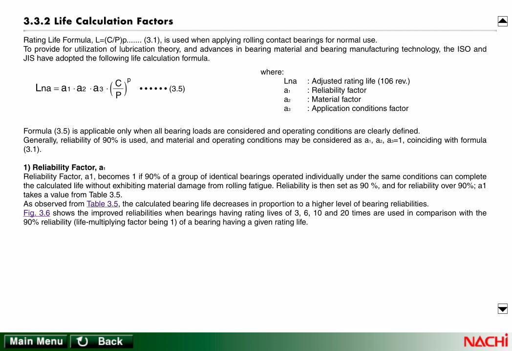
Rating Life Formula, L=(C/P)p....... (3.1), is used when applying rolling contact bearings for normal use.To provide for utilization of lubrication theory, and advances in bearing material and bearing manufacturing technology, the ISO andJIS have adopted the following life calculation formula.
Formula (3.5) is applicable only when all bearing loads are considered and operating conditions are clearly defined.Generally, reliability of 90% is used, and material and operating conditions may be considered as a1, a2, a3=1, coinciding with formula(3.1).
1) Reliability Factor, a1
Reliability Factor, a1, becomes 1 if 90% of a group of identical bearings operated individually under the same conditions can completethe calculated life without exhibiting material damage from rolling fatigue. Reliability is then set as 90 %, and for reliability over 90%; a1takes a value from Table 3.5.As observed from Table 3.5, the calculated bearing life decreases in proportion to a higher level of bearing reliabilities.Fig. 3.6 shows the improved reliabilities when bearings having rating lives of 3, 6, 10 and 20 times are used in comparison with the90% reliability (life-multiplying factor being 1) of a bearing having a given rating life.
L a a ana CP
p
= ⋅ ⋅ ⋅ ( )1 2 3 • • • • • • (3.5)
where:Lna : Adjusted rating life (106 rev.)a1 : Reliability factora2 : Material factora3 : Application conditions factor

Reliability %
a1 factor
99
0.21
98
0.33
97
0.44
96
0.53
95
0.62
90
1
9095989999.599.899.999.95
0.05
0.1
0.2
0.5
1
2
5
10
1 × L
3 × L
6 × L10 × L
20 × L
L : Rating life
Reliability %
Rel
iabi
lity
Mut
iplie
r
Fig 3.6 Reliability Multiplier
Table 3.5 Reliability Factor a1
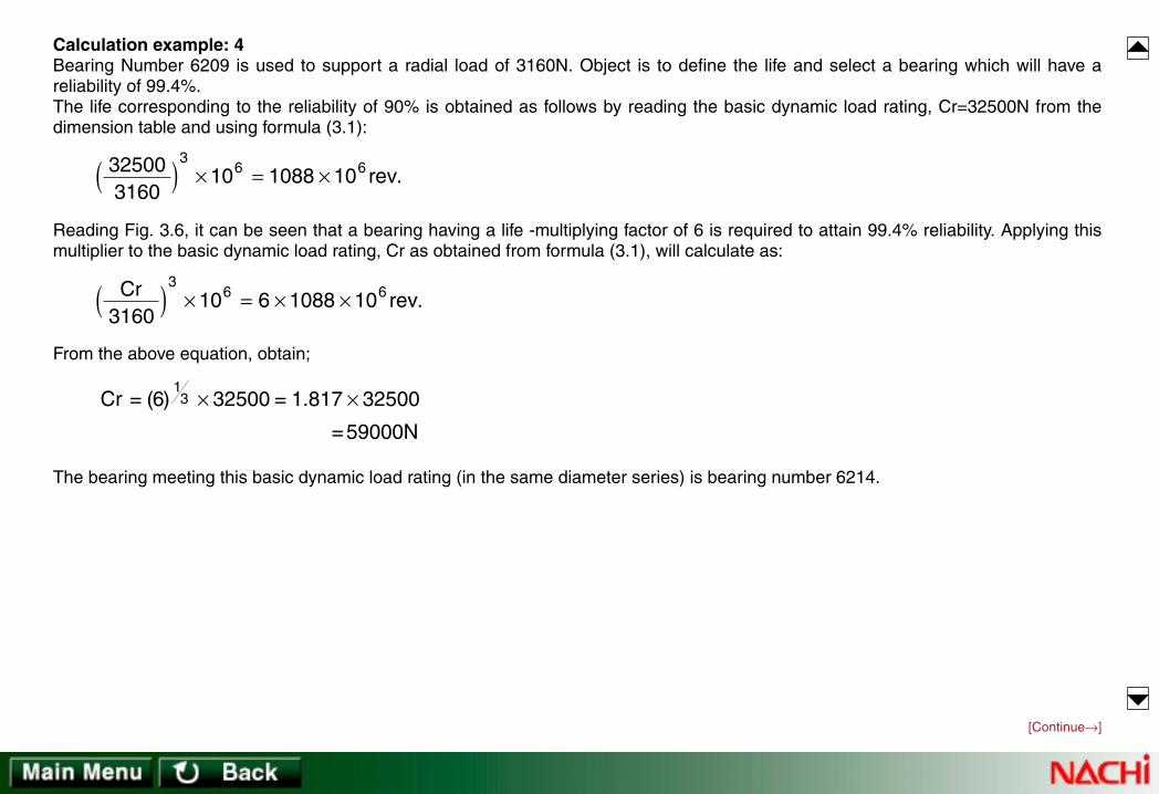
Calculation example: 4Bearing Number 6209 is used to support a radial load of 3160N. Object is to define the life and select a bearing which will have areliability of 99.4%.The life corresponding to the reliability of 90% is obtained as follows by reading the basic dynamic load rating, Cr=32500N from thedimension table and using formula (3.1):
Reading Fig. 3.6, it can be seen that a bearing having a life -multiplying factor of 6 is required to attain 99.4% reliability. Applying thismultiplier to the basic dynamic load rating, Cr as obtained from formula (3.1), will calculate as:
From the above equation, obtain;
The bearing meeting this basic dynamic load rating (in the same diameter series) is bearing number 6214.
325003160
10 1088 103
6 6( ) × = × rev.
[Continue→]
Cr rev3160
10 6 1088 103
6 6( ) × = × × .
Cr = × = ×( ) .6 32500 1 817 3250013
=59000N

[→Continue]
2) Material factor, a2
Material factor, a2, is the adjustment factor applied as an increase to rating life for type and quality of material, special manufacturingprocess and/or special design.The basic dynamic load rating, Cr (or Ca), listed in the bearing dimension tables reflects both the use of vacuum-degassed, high-carbon chrome bearing steel for all NACHI rolling contact bearings as well as improvements in manufacturing technology. The a2-factorhas a base value of 1 for NACHI standard parts.Unless specialty steels are utilized, a2 is defined as 1 when calculating the life using the formula (3.5).
3) Application condition factor, a3
The application condition factor, a3, is used to consider bearing load conditions, lubricating conditions, and temperature conditions.Factor a3 is set as 1 if the rolling elements and raceway surfaces are separated (good lubricating condition). When lubricatingconditions are poor (as in the following cases), a3 is less than 1:• When the operating speed is <dm · n of 10,000. (Where dm · n=rolling element pitch diameter in millimeters times the speed inrevolutions-per-minute).• When lubricant will tend to deteriorate rapidly.At present, it is difficult to quantify the application condition factor because of the many variables involved.Because factors a2 and a3 have interactive effects on each other, these two factors are treated as one value (a2) (a3). When lubricationand application conditions are good, the value (a2) (a3) can be set as equal to 1. In case of poor lubrication such as when lubricant viscosity is considerably low, please consult NACHI.
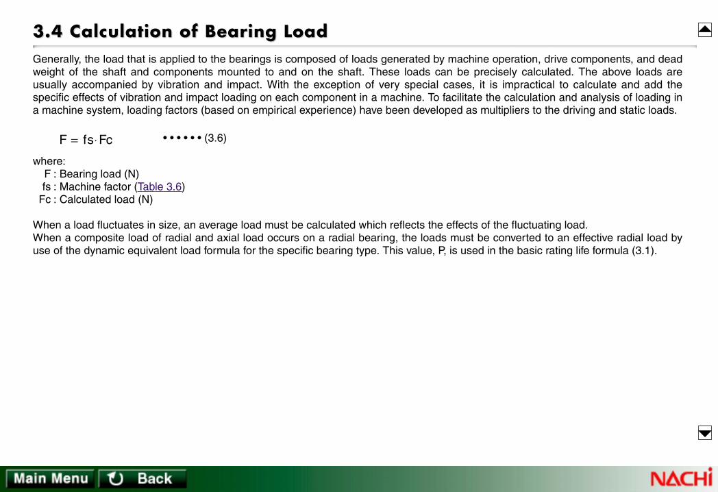
3.4 Calculation of Bearing Load3.4 Calculation of Bearing LoadGenerally, the load that is applied to the bearings is composed of loads generated by machine operation, drive components, and deadweight of the shaft and components mounted to and on the shaft. These loads can be precisely calculated. The above loads areusually accompanied by vibration and impact. With the exception of very special cases, it is impractical to calculate and add thespecific effects of vibration and impact loading on each component in a machine. To facilitate the calculation and analysis of loading ina machine system, loading factors (based on empirical experience) have been developed as multipliers to the driving and static loads.
where:F : Bearing load (N)fs : Machine factor (Table 3.6)
Fc : Calculated load (N)
When a load fluctuates in size, an average load must be calculated which reflects the effects of the fluctuating load.When a composite load of radial and axial load occurs on a radial bearing, the loads must be converted to an effective radial load byuse of the dynamic equivalent load formula for the specific bearing type. This value, P, is used in the basic rating life formula (3.1).
• • • • • • (3.6)F fs Fc= ⋅

Smooth running machinery (no impact) ; motors, conveyors,turbo compressor, paper manufacturing machinery
Machine with low impact; reciprocating pumps, internalcombustion engine, hoists, cranes
Machines with high impact; shears, crushers, rolling mill equipment
Flat leather belt (with tension pulley)
Flat leather belt (without tension pulley)SilkRubber Balata
V-belt
Steel strip belt
Cotton belt / Hemp belt
Precision ( Pitch and form errors ≤ 0.02mm )
Normal ( Pitch and form errors 0.02 ~ 0.1mm )
1 ~ 1.2
1.2 ~ 1.5
1.5 ~ 3.0
1 ~ 1.1
1.1 ~ 1.3
fsType of Machine
Type of drive
fzType of gear
1.75 ~ 2.5
2.25 ~ 3.5
1.5 ~ 2
4 ~ 6
2 ~ 6
f1
Notes : 1. For low speed, use top value
Table 3.7 Belt Drive Factors, ( f1)
Table 3.8 Gear Precisiion Factors, ( fz)
Table 3.6 Machine Factors, ( fs)

3.4.2 Gear Drives3.4.2 Gear Drives
Shaft load from gear drives are calculated using the transfer power and type of gear.Helical, bevel and worm gears transmit radial loads and create an axial load component, while spur gears transmit only radial loads.Gear load formulas described below refer to spur gears.
3.4.1 Belt Drives3.4.1 Belt Drives
Transferring of power through belt drives requires on initial belt tension. Radial load, K, that occurs from this tension can be calculatedas follows:
Load that works on the shaft through the pulley is calculated by multiplying the effective transfer power, Kt, by the belt drive factors, f1,
from Table 3.7.Generally,
K f Kt= ⋅ 1 • • • • • • (3.9)
where:K : Radial load (N) applied to the pulley transferred by the beltf
1: Belt drive factor (Table 3.7)
kt kg
ks
Fig 3.7
M Hn
Kt Mr
Ks Kt
Kg Kt Ks Kt
= ⋅
=
= ⋅
= + = ⋅
955000
2 2
tan
sec
α
α
• • • • • • (3.10)
• • • • • • (3.11)
• • • • • • (3.12)
• • • (3.13)
where:M : Rotating gear moment (N • cm)Kt : Tangential component of force (N)Ks : Radial component of force (N)Kg : Total gear load (N)H : Transfer power (kW)n : Rotating speed (rpm)r : Drive gear pitch radius (cm)
α : Pressure angle of gear (º )
where:M : Rotating moment of pulley (N • cm)Kt : Effective transfer power of belt (N)
(tension side minus slack side)H : Transfer power (kW)n : Rotating speed of pulley (rpm)r : Radius of pulley (cm)
M Hn
Kt Mr
= ⋅
=
955000 • • • • • • (3.7)
• • • • • • (3.8)
[Continue→]

Kg, the total theoretical gear load, must be multiplied by both the gear precision factor and the machine factor (the latter of which takesinto account impact and other forces dependent on machinery type).
3.4.3 Load Distribution to Bearings3.4.3 Load Distribution to Bearings
Load applied to a point on the shaft is distributed to the bearings supporting the shaft.Reference Fig. 3.8,
K fz f s Kg= ⋅ ⋅ • • • • • • (3.14)where:
K : Gear load transmitted to shaft (N)fz : Gear precision factor (Table 3.8)fs : Machine factor (Table 3.6)
[→Continue]
X y
m
KW
FrΙΙ
FrΙFig 3.8
Fr =
= m
Ι
ΙΙ
ll
l
+ ++
−+
m K xx y
W
Fr Ky
x yW
• • • • • • (3.15)
• • • • • • (3.16)
where:FrI : Load working on bearing I (N)FrII : Load working on bearing II (N)
K : Gear load transmitted to shaft (N)W : Shaft Weight (N)
l,m,x,y : Relative positions of the points of applied force

In formula (3.17), if rotating speed is constant, and (n1 + n2 + ........... + nn ) is referencedas applied time, then n1, n2 and nn , can be replaced by time periods t1, t2, ............... tn
respectively, in the formula.
(2) Linear Load FluctuationWhen the load fluctuates almost linearly (see Fig. 3.10), the following formula is used toobtain the average load.
3.4.4 A3.4.4 Averaging Fluctuating Loadsveraging Fluctuating Loads
A large load will have an emphasized effect on bearing life even if it is applied only for a very short duration of the total life-span of thebearing.When the size of bearing load fluctuates with a defined cycle, bearing life may be calculated by deriving an average load simulatingthe affects of the fluctuating load.
(1) Step Type Load Fluctuation
Fm F F 13
23
min max+·=· • • • • • • (3.18)
where:Fm : Average load (N)Fmin : Minimum load (N)Fmax : Maximum load (N)
Fmin
LN
FmaxF
Fm
Fig 3.10
n1 n2 n3 nn
F1
F2
F3
Fm
Fn
LN
Fig 3.9
Fm F n F n F nn n n
p pn
pn
n
p= + ⋅ ⋅ ⋅ +
+ + ⋅ ⋅ ⋅ ⋅ ⋅ ⋅ ⋅ + 1 1 2 2
1 2• • • • • • (3.17)
where:Fm : Average of fluctuating load (N)
n1 : Total number of revolutions at load F1 (rev.)n2 : Total number of revolutions at load F2 (rev.)nn : Total number of revolutions at load Fn (rev.)p : 3 for ball; 10/3 for roller bearings
[Continue→]

(3) Dynamic plus static load fluctuationWhere load F1 of a constant size and direction, is combined with a constantly revolving load F2 causedby an unbalanced load on the bearing (see Fig. 3.11), the average load is calculated using formula 3.19.
Value of A is taken from Fig. 3.12.
Calculation example: 5A Single-row Deep-groove ball bearing is loaded with the fluctuating radial loads shown below.Object: to obtain an average radial load on the bearing.
F1=100N: 800 rpm for 6 secF2= 50N: 1800 rpm for 20 secF3=200N: 3600 rpm for 12 sec
Numbers of revolution for the individual loads F1, F2 and F3 are derived for the formula as follows.
Therefore,
From formula (3.17),
[→Continue]
F1
F2
Fig 3.11
0.2 0.4 0.6 0.8 1.00
0.5
1.0
1.5A
F1
F1+F2
Fig 3.12
n1660
800 80= × = rev. 1260
3600 720= × = rev.n32060
1800 600= × = rev.n2
n n n n= + + =1 2 3 1400 rev.
Fm
N
=
× + × + ×
=
100 80 50 600 200 7201400
162
3 3 33
Fm F AF 1 + 2·=· • • • • • • (3.19)

3.5 Dynamic Equivalent Load3.5 Dynamic Equivalent LoadDynamic equivalent load refers to a load having constant direction and size such that theoretical calculations of bearing life using thisload will simulate actual bearing life. This load is called dynamic equivalent radial load when calculated for radial bearings anddynamic equivalent axial load when calculated for thrust bearings.In formula (3.1) expressing the relation between the bearing load and bearing life, bearing load, P, is either radial or axial load. Sinceradial and axial loads often occur simultaneously, the radial and axial loads must be converted to composite load within the dynamicequivalent load formula.
3.5.1 Dynamic Equivalent Radial Load3.5.1 Dynamic Equivalent Radial Load
Dynamic equivalent radial load for radial bearings is calculated using the formula:
In the above formula, if the axial load to radial load ratio, Fa/Fr, isless than or equal to e (a value determined by the bearing size andload as shown in the dimension tables), X, Y, and Pr will be asfollows:
X = 1Y = 0Pr = Fr
• • • • • • (3.20)Pr=XFr+YFawhere:
Pr : Dynamic equivalent radial load (N)Fr : Radial load (N)Fa : Axial load (N)X : Radial load factor
(from dimensional tables)Y : Axial load factor
(from dimensional tables)
3.5.2 Dynamic Equivalent Axial Load3.5.2 Dynamic Equivalent Axial Load
While most thrust bearings are incapable of supporting any radial load, Spherical roller thrust bearings will support some radial load.For Spherical roller thrust bearings, the dynamic equivalent axial load is derived using the formula:
• • • • • • (3.21)Pa=Fa+1.2Fr where:Pa : Dynamic equivalent axial load (N)Fa : Axial load (N)Fr : Radial load (N)Fr / Fa must be ≤ 0.55
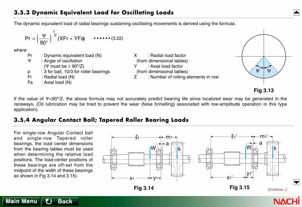
For single-row Angular Contact balland single-row Tapered rollerbearings, the load center dimensionsfrom the bearing tables must be usedwhen determining the relative loadpositions. The load-center positions ofthese bearings are off-set from themidpoint of the width of these bearingsas shown in Fig 3.14 and 3.15).
3.5.3 Dynamic Equivalent Load for Oscillating Loads3.5.3 Dynamic Equivalent Load for Oscillating Loads
The dynamic equivalent load of radial bearings sustaining oscillating movements is derived using the formula:
If the value of Ψ<90º/Z, the above formula may not accurately predict bearing life since localized wear may be generated in theraceways. (Oil lubrication may be tried to prevent the wear (false brinelling) associated with low-amplitude operation in this typeapplication).
3.5.4 Angular Contact Ball; T3.5.4 Angular Contact Ball; Taperapered Roller Bearing Loadsed Roller Bearing Loads
Pr ( )=°( ) +
ψ90
1p
XFr YFa • • • • • • (3.22)
ψ ψ
Fig 3.13
where:Pr : Dynamic equivalent load (N)Ψ : Angle of oscillation
(Ψ must be ≥ 90º/Z)p : 3 for ball, 10/3 for roller bearingsFr : Radial load (N)Fa : Axial load (N)
X : Radial load factor(from dimensional tables)
Y : Axial load factor(from dimensional tables)
Z : Number of rolling elements in row
m1
Wa
y1
1
k
x1
Fig 3.14
m1'
Wa
y1'
1'
k
x1'
Fig 3.15 [Continue→]
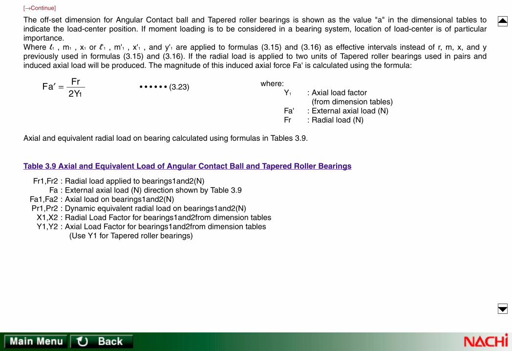
Fr1,Fr2Fa
Fa1,Fa2Pr1,Pr2
X1,X2Y1,Y2
: Radial load applied to bearings1and2(N): External axial load (N) direction shown by Table 3.9: Axial load on bearings1and2(N): Dynamic equivalent radial load on bearings1and2(N): Radial Load Factor for bearings1and2from dimension tables: Axial Load Factor for bearings1and2from dimension tables
(Use Y1 for Tapered roller bearings)
[→Continue]
The off-set dimension for Angular Contact ball and Tapered roller bearings is shown as the value "a" in the dimensional tables toindicate the load-center position. If moment loading is to be considered in a bearing system, location of load-center is of particularimportance.Where l1 , m1 , x1 or l'1 , m'1 , x'1 , and y'1 are applied to formulas (3.15) and (3.16) as effective intervals instead of r, m, x, and ypreviously used in formulas (3.15) and (3.16). If the radial load is applied to two units of Tapered roller bearings used in pairs andinduced axial load will be produced. The magnitude of this induced axial force Fa' is calculated using the formula:
Axial and equivalent radial load on bearing calculated using formulas in Tables 3.9.
Fa FrY
′ =2 1
• • • • • • (3.23) where:Y1 : Axial load factor
(from dimension tables)Fa' : External axial load (N)Fr : Radial load (N)
Table 3.9 Axial and Equivalent Load of Angular Contact Ball and Tapered Roller Bearings

Bearing arrangement
Fr ΙΙ Fr Ι
Fa
ΙΙ Ι
Fr ΙΙ Fr Ι
Fa
ΙΙ Ι
Fr ΙΙ Fr Ι
Fa
Ι ΙΙ
Fr ΙΙ Fr Ι
Fa
Ι ΙΙ
Fr ΙΙ Fr Ι
Fa
ΙΙ Ι
Fr ΙΙ Fr Ι
Fa
ΙΙ Ι
Fr ΙΙ Fr Ι
Fa
Ι ΙΙ
Fr ΙΙ Fr Ι
Fa
Ι ΙΙ
Load conditions Dynamic equivalent radial loadAxial load
Fa ≥ 0.5( - )Fa ΙΙ =Fa Ι +Fa Pr ΙΙ =X ΙΙ Fr ΙΙ +Y ΙΙ (Fa Ι +Fa)
Fa Ι =0.5 Pr Ι =Fr Ι Fr ΙΙ Y ΙΙ
Fr Ι Y Ι
Fr Ι Y Ι
Pr ΙΙ =Fr ΙΙ
Pr Ι =X Ι Fr Ι +Y Ι (Fa ΙΙ +Fa)
Fa ΙΙ =0.5
Fa Ι =Fa ΙΙ +Fa
Fr ΙΙ Y ΙΙ
Fa ≥ 0.5( - )Fr ΙΙ Y ΙΙ
Fr Ι Y Ι
Fa ΙΙ =0.5 Pr ΙΙ =Fr ΙΙ
Fa Ι =Fa ΙΙ -Fa Pr Ι =X Ι Fr Ι +Y Ι (Fa ΙΙ -Fa)Fr ΙΙ Y ΙΙ
Fa < 0.5( - )Fr ΙΙ Y ΙΙ
Fr Ι Y Ι
Pr ΙΙ =X ΙΙ Fr ΙΙ +Y ΙΙ (Fa Ι -Fa)
Pr Ι =Fr Ι
Fa ΙΙ =Fa Ι -Fa
Fa Ι =0.5 Fr Ι Y Ι Fa < 0.5( - )Fr ΙΙ
Y ΙΙ Fr Ι Y Ι
Notes : 1. Equalities apply when the bearing clearance and preload are 0.2. Radial load applied in reverse direction to the arrows above will be also treated as positive values.
Table 3.9 Axial and Equivalent Load of Angular Contact Ball and Tapered Roller Bearings

3.6.1 Basic Static Load Rating3.6.1 Basic Static Load Rating
Load applied to stationary bearings can create permanent indentations in the load surfaces. While some level of deformation can betolerated, a level of deformation will be reached where noise and vibration during operation of the bearing, will make the bearingunusable.The term "Basic static load rating" refers to the maximum contact stress value of the static load where the rolling element andraceways contact. The ratings are:
• Self-aligning ball bearing • • • 4600MPa• Other ball bearings • • • 4200MPa• Roller bearings • • • 4000 MPa
With these contact stresses, the sum of deformations (ball/roller and raceway) is approximately 1/10000 of the diameter of the rollingelement.Basic static load ratings are shown in the dimension tables for each bearing number. The symbol Cor is for radial bearings and thesymbol Coa is for thrust bearings.
3.6 Basic Static Load Rating and Static Equivalent Load3.6 Basic Static Load Rating and Static Equivalent Load
3.6.2 Static Equivalent Load3.6.2 Static Equivalent Load
Static equivalent load is the static load that reflects the actual load conditions to the contact section of the rolling elements andraceway receiving the maximum stress. For radial bearings, radial load of a constant direction and size is called the static equivalentradial load, and for thrust bearings, axial load of a constant direction and size is called the static equivalent axial load.
1) Static equivalent radial loadTo calculate the static equivalent radial load of a radial bearing supporting simultaneous radial and axial loads, the larger of the valuesobtained from formulas (3.24) and (3.25) are to be used
• • • • • • (3.24)
• • • • • • (3.25)
Por=XoFr+YoFaPor=Fr
where:Por : Static equivalent radial load (N)
Fr : Radial load (N)Fa : Axial load (N)Xo & Yo: Static radial and axial load factors from dimension tables
[Continue→]

• • • • • • (3.26)
3.6.3 Safety Factor3.6.3 Safety Factor
The basic static load rating is considered as the limiting load for general applications. In terms of a safety factor, this means that, bydefinition, a safety factor, So, is set as a base of 1. An application may require a larger or allow a smaller safety factor. Table 3.10provides a guide for selection of the safety factor, So, to be used with formula (3.27) for calculation of the maximum (weighted) staticequivalent load.
• • • • • • (3.27)Co=So • Pomax where:Co: Basic static load rating (N)(Cor for radial; Coa for thrust bearings)So: Safety factor(select from Table 3.10)Pomax: Static equivalent load (N)
High rotating accuracy is needed
Vibration and/or impact present
Small amount of permanent deformation is tolerable
2
1.5
0.7
Ball BearingsApplication condition
Normal operating conditions 1
3
2
1
Roller BearingsSo
1.5
Note : So > 4 for spherical roller thrust bearings
2) Static equivalent axial loadStatic equivalent axial load for Spherical Thrust bearings is calculated using formula (3.26)
where:Poa : Static equivalent axial load (N)Fa : Axial load (N)
Fr : Radial load (N)Fr/Fa must be ≤ 0.55
Poa=Fa+2.7Fr
Table 3.10 Static Safety Factor (So)
[→Continue]

Cylindrical roller bearings are generally used for supporting radial loads only. Bearings having flanges or loose ribs on both the innerand outer rings (such as on configurations NJ, NF, and NUP), however, are capable of supporting some amount of axial load. Sinceany axial loading on a cylindrical roller bearing is supported by a "sliding" action between the roller ends and flanges, allowable axialload is based on the limiting values of heat, seizure, and wear caused by this "sliding" contact.Permissible axial loading (no consideration of bearing life as a radial bearing) on Cylindrical roller bearings is calculated using thefollowing formula.
3.7 Axial Load Capacity of Cylindrical Roller Bearings3.7 Axial Load Capacity of Cylindrical Roller Bearings
Bearing series K1
1000, 200, 200E300, 300E, 400
0.2
0.42200, 2200E, 2300, 2300E
pv : Application factor from Table 3.11.1λ : Bearing type factor from Table 3.11.2n : Rotating speed (rpm)
When cylindrical roller bearings are applied axial load, additionalconsiderations are required as follows;• Apply sufficient radial load to overcome axial load• Supply sufficient lubricant between roller ends and flanges• Use lubricant which has good film strength (pressure resistant)
properties• Practice good bearing mounting accuracy (see section 8.3)• Allow sufficient running-in• Minimize radial bearing clearance
Allowable axial load ≤ K1 · Fr
• • • • • • Allowable axial load (N)F pvn
a = ( ) λ
However, there is another limits shown by the following formulabecause Fa exceeding the limits cause abnormal roller movement
5400 ~ 6900
2600 ~ 3200
(pv)Operating conditions (Load and lubrication)
Intermittent axial load, Good heat conduction and Good cooling or Very large amount of lubricant
Intermittent axial load, Good heat conduction and Large amount of lubricant
1300 ~ 1600Continuous axial load and Oil lubrication or Intermittent axial load and Grease lubrication
1900 ~ 2200Oil lubrication, Good heat conduction or Good cooling
690 ~ 780Continuous axial load and Grease lubrication
Diameter Series λ0234
19d32d45d60d
d=Bearing bore (mm)
Table 3.11.1 Application Factor (pv)
Table 3.11.2 Bearing Type Factor λ

4.2 Radial Bearings(Except T4.2 Radial Bearings(Except Taperapered Roller Bearings)ed Roller Bearings)TTable 4.2.1able 4.2.1
4.3 Boundar4.3 Boundary Dimensions of Ty Dimensions of Taperapered Roller Bearingsed Roller Bearings
4.4 Boundar4.4 Boundary Dimensions of Thry Dimensions of Thrust Bearings with Flat Back Faceust Bearings with Flat Back Face
4.5 Dimensions of Snap Ring Gr4.5 Dimensions of Snap Ring Grooves and Snap Ringsooves and Snap Rings• Table 4.5.1 Dimensions of Snap Ring Grooves for Bearing Dimension Series 18 and 19• Table 4.5.2 Snap Ring Dimensions for Bearing Dimension Series 18 and 19• Table 4.5.3 Dimensions of Snap Ring Grooves for Bearing Diameter Series 0, 2, 3 and 4• Table 4.5.4 Snap Ring Dimensions for Bearing Diameter Series 0, 2, 3 and 4
TTable 4.2.2able 4.2.2• Diameter series 1• Diameter series 3
• Diameter series 2• Diameter series 4
• Diameter series 7• Diameter series 9
• Diameter series 8• Diameter series 0
4.1 Boundar4.1 Boundary Dimensionsy Dimensions
4. Boundar4. Boundary Dimensionsy Dimensions and Nomenclature and Nomenclature
4.6 NACHI Bearing Numbers4.6 NACHI Bearing Numbers
TTable 4.3.2able 4.3.2TTable 4.3.1able 4.3.1• Diameter series 2 • Diameter series 3• Diameter series 9 • Diameter series 1 • Diameter series 0
TTable 4.4.2able 4.4.2TTable 4.4.1able 4.4.1• Diameter series 2• Diameter series 0
• Diameter series 1
TTable 4.4.4able 4.4.4TTable 4.4.3able 4.4.3• Diameter series 4• Diameter series 5
• Diameter series 3

4.1 Boundar4.1 Boundary Dimensions of Rolling Contact Bearingsy Dimensions of Rolling Contact Bearings
4. Boundar4. Boundary Dimensions and Bearing Numbersy Dimensions and Bearing Numbersof Rolling Contact Bearingsof Rolling Contact Bearings
Boundary dimensions have been established in a standard plan for metric rolling contact bearings to facilitate the selection process,improve availability, and to limit the necessity for use of high cost, non-standard parts.Boundary dimensions standards include the bore diameter (d), outside diameter (D), width (B), assembly width (T) or height (H), andthe chamfer dimension (r) of bearings.Boundary dimensions are standardized by the International Organization for Standardization (ISO 15) and also Japanese IndustrialStandard (JIS B 1512).NACHI has adopted the ISO boundary dimension standards. Figures 4.6 and 4.7 show the relationship of the dimensions for radialand thrust rolling contact bearings (except for Tapered roller bearings).
The diameter series is a series of standard outside diameters with standard bore diameters. Several series of outside diameters are set in stages to the same bearing bore diameter. Diameter series are labeled by single digit numbers 7, 8, 9, 0, 1, 2, 3, and 4.
Width or height series is a series of standard widths or heights with the same bore diameter within the same diameter series of bearings. These width or height series are labeled with single digit numbers. Width series 8, 0, 1, 2, 3, 4, 5, and 6 for radial bearings and height series 7, 9, 1, and 2 are for thrust bearings.
Dimension series = width or height series number + Diameter series. Dimension series are labeled with a two digit number by combining numbers for the width or height series to the numbers for the diameter series. The two digit number has the width or height series in the lead position.
Diameterseries
Width or Heightseries
Dimensionseries
Diameter series is in ascending order by diameter size with number 7 the smallest and 4 the largest.
Each radial bearing diameter series has width series with numbers 8, 0, 1, 2, 3, 4, 5 and 6. Number 8 is the minimum width to the same bore and outside diameter. Number 6 is the maximum width
Each thrust bearing diameter series has width series with number 7, 9, 1 and 2. Number 7 is the minimum width to the same bore and outside diameter. Number 2 is the maximum width
Series Definition Remarks
Table 4.1 Boundary Dimensions Terminolory

T
r
r
r
r
Fig 4.3Single-direction Thrust Ball Bearings
d
D
φ
φ
r
r
Tr
r
Fig 4.5Spherical Roller Thrust Bearings
d
D
φ
φ
T2
T2
T1
r
r
rr
B
r1
r1r1
r1
Fig 4.4Double-direction Thrust Ball Bearings
d
d2
Dφ
φ
φ
B
D
r
d
r rr
rr
r rB
r
r r
r
Cylindrical Bore Tapered bore ( or taper)
D
d
112
130
Fig 4.1 Radial Bearings (except Tapered Roller Baerings)φ φ φ φ D
d
TC
B
r
r
r
r
Fig 4.2 Tapered Roller Bearings
φ φ
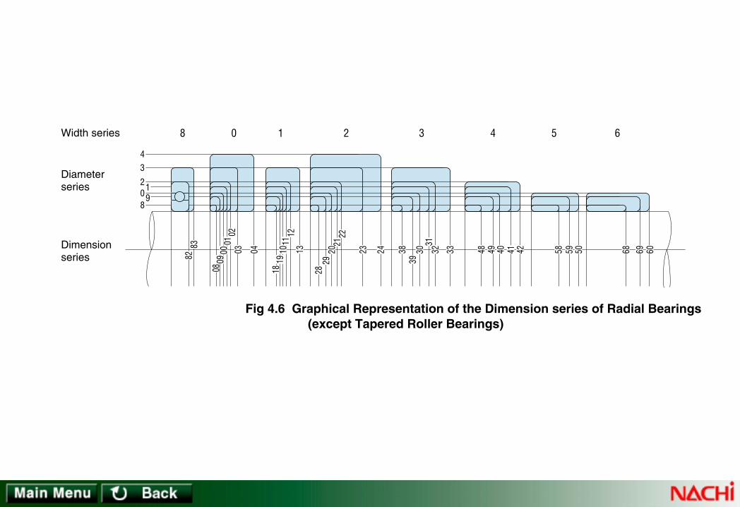
Width series
Diameterseries
Dimensionseries
891
02
34
8 0 1 2 3 4 5 6
8283
0809
0001
0203 04
1819
1011
1213
2829
2021
22
23 24 3839
3031
32 33 48 49 40 41 42 58 59 50 68 69 60
Fig 4.6 Graphical Representation of the Dimension series of Radial Bearings (except Tapered Roller Bearings)

Heightseries
Dimensionseries
Diameterseries
0
7
1 2 3 4
9
1
2
7071
7273
74
90919293
94
101112
13
14
22
23
24 Fig 4.7 Graphical Indication of Dimension Series of Thrust Bearings

Single row, radial ball bearings
Double row, radial ball bearings
Cylindrical roller bearings
Spherical roller bearings
Bore No. d
Bearing borediameterNominal
Bea
ring
outs
ide
diam
eter
D
Bea
ring
outs
ide
diam
eter
D
Chamferdimension
Chamferdimension
Diameter series 7 Diameter series 8Width series
2Dimension series
27
Width B
17 3717
37
~
rmin
1 3Width series
Dimension series
Width B
08 18 28 38 48 58 6818
68
~
08
rmin
0 1 2 3 4 5 6
6867
2 2.53
4 5 6
7 8
10
11 12 14
– –1.8
22.33
333.5
3.53.54.5
0.050.050.05
0.050.080.08
0.080.080.1
0.10.10.1
– – –
– –2.5
2.52.53
3 – –
0.811
1.21.52
222.5
2.52.53
2.534
567
91113
141617
–––
–––
–––
–––
1 1
1.2
1.5 1.82
2.53
3.5
3.544
–––
–––
–––
–––
0.050.050.05
0.080.080.1
0.10.150.15
0.150.20.2
– – –
– – –
– – –
– 88
– – –
– – –
3.545
555
1.4 1.52
2.3 2.63
456
666
– – –
– – –
– – –
– – –
– – –
– – –
– – –
– – –
/0.61 /1.5
2 /2.53
4 5 6
7 8 9
0.61 1.5
2 2.53
4 5 6
7 8 9
Remarks: 1. rmin is the smallest chamfer dimension.2. The chamfer dimensions given in this table do not necessarily apply to:
(1) the groove side of bearing rings with snap ring groove(2) the flangeless side of thin cylindrical roller bearing rings
(3) the front face side of angular contact bearing(4) inner rings of bearings with tapered bore
Table 4.2.1 Boundary Dimensions of Diameter Series 7, 8 (1/8) Unit : mm

Single row, radial ball bearings
Double row, radial ball bearings
Cylindrical roller bearings
Spherical roller bearings
Bore No. d
Bearing borediameterNominal
Bea
ring
outs
ide
diam
eter
D
Bea
ring
outs
ide
diam
eter
D
Chamferdimension
Chamferdimension
Diameter series 7 Diameter series 8Width series
2Dimension series
27
Width B
17 3717
37
~
rmin
1 3Width series
Dimension series
Width B
08 18 28 38 48 58 6818
68
~
08
rmin
0 1 2 3 4 5 6
6867
15 18 21
23 27
–
32 –
37
–––
4.555
55 –
5 –5
– – –
0.10.20.2
0.20.2 –
0.2 –0.2
– – –
– – –
– – –
– – –
– – –
344
44 –
4 –4
– – –
192124
263234
374042
444752
–––
–44
444
444
555
577
777
777
–––
–0.30.3
0.30.30.3
0.30.30.3
0.30.30.3
0.30.30.3
0.30.30.3
0.30.30.3
999
912–
12– 12
– 1212
666
68–
8–8
–88
777
71010
101010
101010
– – –
– 1616
161616
161616
– – –
– 2222
222222
222222
00 01 02
03 04 /22
05 /28 06
/32 07 08
10 12 15
17 20 22
25 28 30
32 35 40
Remarks: 1. rmin is the smallest chamfer dimension.2. The chamfer dimensions given in this table do not necessarily apply to:
(1) the groove side of bearing rings with snap ring groove(2) the flangeless side of thin cylindrical roller bearing rings
(3) the front face side of angular contact bearing(4) inner rings of bearings with tapered bore
Table 4.2.1 Boundary Dimensions of Diameter Series 7, 8 (2/8) Unit : mm

Single row, radial ball bearings
Double row, radial ball bearings
Cylindrical roller bearings
Spherical roller bearings
Bore No. d
Bearing borediameterNominal
Bea
ring
outs
ide
diam
eter
D
Bea
ring
outs
ide
diam
eter
D
Chamferdimension
Chamferdimension
Diameter series 7 Diameter series 8Width series
2Dimension series
27
Width B
17 3717
37
~
rmin
1 3Width series
Dimension series
Width B
08 18 28 38 48 58 6818
68
~
08
rmin
0 1 2 3 4 5 6
6867
–––
–––
–––
–––
– – –
– – –
– – –
– – –
– – –
– – –
– – –
– – –
– – –
– – –
– – –
– – –
– – –
– – –
– – –
– – –
586572
788590
95100110
115120125
457
778
889
999
779
101010
101013
131313
0.30.30.3
0.30.30.3
0.30.30.3
0.30.30.3
0.30.30.3
0.30.60.6
0.60.61
111
131517
182020
202025
252525
81011
121313
131316
161616
101213
141515
151519
191919
182023
242727
272734
343434
232730
323636
363645
454545
09 10 11
12 13 14
15 16 17
18 19 20
45 50 55
60 65 70
75 80 85
90 95
100
Remarks: 1. rmin is the smallest chamfer dimension.2. The chamfer dimensions given in this table do not necessarily apply to:
(1) the groove side of bearing rings with snap ring groove(2) the flangeless side of thin cylindrical roller bearing rings
(3) the front face side of angular contact bearing(4) inner rings of bearings with tapered bore
Table 4.2.1 Boundary Dimensions of Diameter Series 7, 8 (3/8) Unit : mm

Single row, radial ball bearings
Double row, radial ball bearings
Cylindrical roller bearings
Spherical roller bearings
Bore No. d
Bearing borediameterNominal
Bea
ring
outs
ide
diam
eter
D
Bea
ring
outs
ide
diam
eter
D
Chamferdimension
Chamferdimension
Diameter series 7 Diameter series 8Width series
2Dimension series
27
Width B
17 3717
37
~
rmin
1 3Width series
Dimension series
Width B
08 18 28 38 48 58 6818
68
~
08
rmin
0 1 2 3 4 5 6
6867
–––
–––
–––
–––
–––
–––
–––
–––
–––
–––
–––
–––
–––
–––
–––
–––
–––
–––
–––
–––
130140150
165175190
200215225
240250270
91010
111113
131414
161616
131616
181820
202222
242424
0.30.60.6
0.60.60.6
0.60.60.6
111
111
1.11.11.1
1.11.11.1
1.51.51.5
253030
353540
404545
505050
161919
222224
242727
303030
192323
262630
303434
373737
344040
464654
546060
676767
455454
636371
718080
909090
21 22 24
26 28 30
32 34 36
38 40 44
105110120
130140150
160170180
190200220
Remarks: 1. rmin is the smallest chamfer dimension.2. The chamfer dimensions given in this table do not necessarily apply to:
(1) the groove side of bearing rings with snap ring groove(2) the flangeless side of thin cylindrical roller bearing rings
(3) the front face side of angular contact bearing(4) inner rings of bearings with tapered bore
Table 4.2.1 Boundary Dimensions of Diameter Series 7, 8 (4/8) Unit : mm

Single row, radial ball bearings
Double row, radial ball bearings
Cylindrical roller bearings
Spherical roller bearings
Bore No. d
Bearing borediameterNominal
Bea
ring
outs
ide
diam
eter
D
Bea
ring
outs
ide
diam
eter
D
Chamferdimension
Chamferdimension
Diameter series 7 Diameter series 8Width series
2Dimension series
27
Width B
17 3717
37
~
rmin
1 3Width series
Dimension series
Width B
08 18 28 38 48 58 6818
68
~
08
rmin
0 1 2 3 4 5 6
6867
–––
–––
–––
–––
–––
–––
–––
–––
–––
–––
–––
–––
–––
–––
–––
–––
–––
–––
–––
–––
300320350
380400420
440480500
520540580
191922
252525
253131
313137
282833
383838
384646
464656
111.1
1.51.51.5
1.522
222.1
222
2.12.12.1
2.12.12.1
2.12.13
606069
808080
80100100
100100118
363642
484848
486060
606072
454552
606060
607575
757590
808095
109109109
109136136
136136160
109109125
145145145
145180180
180180218
48 52 56
60 64 68
72 76 80
84 88 92
240260280
300320340
360380400
420440460
Remarks: 1. rmin is the smallest chamfer dimension.2. The chamfer dimensions given in this table do not necessarily apply to:
(1) the groove side of bearing rings with snap ring groove(2) the flangeless side of thin cylindrical roller bearing rings
(3) the front face side of angular contact bearing(4) inner rings of bearings with tapered bore
Table 4.2.1 Boundary Dimensions of Diameter Series 7, 8 (5/8) Unit : mm

Single row, radial ball bearings
Double row, radial ball bearings
Cylindrical roller bearings
Spherical roller bearings
Bore No. d
Bearing borediameterNominal
Bea
ring
outs
ide
diam
eter
D
Bea
ring
outs
ide
diam
eter
D
Chamferdimension
Chamferdimension
Diameter series 7 Diameter series 8Width series
2Dimension series
27
Width B
17 3717
37
~
rmin
1 3Width series
Dimension series
Width B
08 18 28 38 48 58 6818
68
~
08
rmin
0 1 2 3 4 5 6
6867
–––
–––
–––
–––
–––
–––
–––
–––
–––
–––
–––
–––
–––
–––
–––
–––
–––
–––
–––
–––
600620650
680730780
820870920
98010301090
373737
374248
485054
575760
565656
566069
697478
828285
2.12.12.1
2.133
344
445
333
334
445
555
118118118
118128150
150160170
180180190
727272
727888
8895
100
106106112
909090
9098
112
112118128
136136140
160160160
160175200
200218230
243243258
218218218
218236272
272290308
325325345
96 /500 /530
/560 /600 /630
/670 /710 /750
/800 /850 /900
480500530
560600630
670710750
800850900
Remarks: 1. rmin is the smallest chamfer dimension.2. The chamfer dimensions given in this table do not necessarily apply to:
(1) the groove side of bearing rings with snap ring groove(2) the flangeless side of thin cylindrical roller bearing rings
(3) the front face side of angular contact bearing(4) inner rings of bearings with tapered bore
Table 4.2.1 Boundary Dimensions of Diameter Series 7, 8 (6/8) Unit : mm

Single row, radial ball bearings
Double row, radial ball bearings
Cylindrical roller bearings
Spherical roller bearings
Bore No. d
Bearing borediameterNominal
Bea
ring
outs
ide
diam
eter
D
Bea
ring
outs
ide
diam
eter
D
Chamferdimension
Chamferdimension
Diameter series 7 Diameter series 8Width series
2Dimension series
27
Width B
17 3717
37
~
rmin
1 3Width series
Dimension series
Width B
08 18 28 38 48 58 6818
68
~
08
rmin
0 1 2 3 4 5 6
6867
–––
–––
–––
–––
–––
–––
–––
–––
–––
–––
–––
–––
–––
–––
–––
115012201280
136014201500
160017001820
637171
787880
8895–
90100100
106106112
122132140
555
556
66–
566
666
67.57.5
200218218
243243250
280300315
118128128
140140145
165175185
150165165
180180185
206224243
272300300
325325335
375400
–
355400400
438438450
500545
–
/950 /1000 /1060
/1120 /1180 /1250
/1320 /1400 /1500
95010001060
112011801250
132014001500
Remarks: 1. rmin is the smallest chamfer dimension.2. The chamfer dimensions given in this table do not necessarily apply to:
(1) the groove side of bearing rings with snap ring groove(2) the flangeless side of thin cylindrical roller bearing rings
(3) the front face side of angular contact bearing(4) inner rings of bearings with tapered bore
Table 4.2.1 Boundary Dimensions of Diameter Series 7, 8 (7/8) Unit : mm

Single row, radial ball bearings
Double row, radial ball bearings
Cylindrical roller bearings
Spherical roller bearings
Bore No. d
Bearing borediameterNominal
Bea
ring
outs
ide
diam
eter
D
Bea
ring
outs
ide
diam
eter
D
Chamferdimension
Chamferdimension
Diameter series 7 Diameter series 8Width series
2Dimension series
27
Width B
17 3717
37
~
rmin
1 3Width series
Dimension series
Width B
08 18 28 38 48 58 6818
68
~
08
rmin
0 1 2 3 4 5 6
6867
–––
––
–––
––
–––
––
–––
––
–––
––
195020602180
23002430
–––
––
155160165
175190
–––
––
7.57.59.5
9.59.5
345355375
400425
200206218
230250
265272290
300325
– – –
– –
– – –
– –
/1600 /1700 /1800
/1900 /2000
160017001800
19002000
Remarks: 1. rmin is the smallest chamfer dimension.2. The chamfer dimensions given in this table do not necessarily apply to:
(1) the groove side of bearing rings with snap ring groove(2) the flangeless side of thin cylindrical roller bearing rings
(3) the front face side of angular contact bearing(4) inner rings of bearings with tapered bore
Table 4.2.1 Boundary Dimensions of Diameter Series 7, 8 (8/8) Unit : mm

Single row, radial ball bearings
Double row, radial ball bearings
Cylindrical roller bearings
Spherical roller bearings
Bore No. d
Bearing borediameterNominal
Bea
ring
outs
ide
diam
eter
D
Bea
ring
outs
ide
diam
eter
D
Chamferdimension
Chamferdimension
Diameter series 9 Diameter series 0
Dimension series
Width series
rminWidth B
09 19 29 39 49 59 69 0919
39
~
49
69
~
0 1 2 3 4 5 6Dimension series
rminWidth B
Width series
10
60
~ 00 10 20 30 40 50 60 00
0 1 2 3 4 5 6
240230
NN30N10
6070
6979 160
239
NN49
/0.61 /1.5
2 /2.53
4 5 6
7 8 9
0.61 1.5
2 2.53
4 5 6
7 8 9
–45
678
111315
171920
– – –
– – –
– – –
– – –
– 1.62
2.3 2.53
445
566
– – –
– – –
– 1010
101111
–––
–––
–––
–––
–0.10.15
0.150.150.15
0.150.20.2
0.30.30.3
––6
789
121417
192224
– – –
– – –
– – –
– – –
– – –
– – –
– – –
89
10
– – –
– – –
– – –
– 1415
–––
–––
–––
–––
– –0.15
0.150.150.15
0.20.20.3
0.30.30.3
– – –
– – –
– – –
– – –
– 2.3 2.6
3 3.54
567
799
– – –
– – –
– – –
– – –
– – –
– – –
– – –
– – –
–––
–––
–0.150.15
0.150.20.3
– – 2.5
2.8 2.83
456
677
– – 3
3.545
679
101112
– – –
– – –
– – –
– 1920
– – –
– – –
– – –
– 2527
Remarks: 1. rmin is the smallest chamfer dimension.2. The chamfer dimensions given in this table do not necessarily apply to:
(1) the groove side of bearing rings with snap ring groove(2) the flangeless side of thin cylindrical roller bearing rings
(3) the front face side of angular contact bearing(4) inner rings of bearings with tapered bore
Table 4.2.1 Boundary Dimensions of Diameter Series 9, 0 (1/8) Unit : mm

Single row, radial ball bearings
Double row, radial ball bearings
Cylindrical roller bearings
Spherical roller bearings
Bore No. d
Bearing borediameterNominal
Bea
ring
outs
ide
diam
eter
D
Bea
ring
outs
ide
diam
eter
D
Chamferdimension
Chamferdimension
Diameter series 9 Diameter series 0
Dimension series
Width series
rminWidth B
09 19 29 39 49 59 69 0919
39
~
49
69
~
0 1 2 3 4 5 6Dimension series
rminWidth B
Width series
10
60
~ 00 10 20 30 40 50 60 00
0 1 2 3 4 5 6
240230
NN30N10
6070
6979 160
239
NN49
00 01 02
03 04 /22
05 /28 06
/32 07 08
10 12 15
17 20 22
25 28 30
32 35 40
222428
303739
424547
525562
– – –
– 77
777
778
667
799
999
101012
131313
131717
171717
202022
–––
–0.30.3
0.30.30.3
0.30.30.3
0.30.30.3
0.30.30.3
0.30.30.3
0.60.60.6
262832
354244
475255
586268
– 78
888
889
999
101011
121414
141516
161718
161617
182222
222425
262728
–0.30.3
0.30.30.3
0.30.30.3
0.30.30.3
0.30.30.3
0.30.60.6
0.60.61
111
8 8 8.5
8.51111
111111
131314
101010
101313
131313
151516
161618
182323
232323
272730
222223
233030
303030
363640
0.30.30.3
0.30.30.3
0.30.30.3
0.60.60.6
889
101212
121213
131415
121213
141616
161819
202021
212123
243030
303234
353638
292930
324040
404345
474850
Remarks: 1. rmin is the smallest chamfer dimension.2. The chamfer dimensions given in this table do not necessarily apply to:
(1) the groove side of bearing rings with snap ring groove(2) the flangeless side of thin cylindrical roller bearing rings
(3) the front face side of angular contact bearing(4) inner rings of bearings with tapered bore
Table 4.2.1 Boundary Dimensions of Diameter Series 9, 0 (2/8) Unit : mm

Single row, radial ball bearings
Double row, radial ball bearings
Cylindrical roller bearings
Spherical roller bearings
Bore No. d
Bearing borediameterNominal
Bea
ring
outs
ide
diam
eter
D
Bea
ring
outs
ide
diam
eter
D
Chamferdimension
Chamferdimension
Diameter series 9 Diameter series 0
Dimension series
Width series
rminWidth B
09 19 29 39 49 59 69 0919
39
~
49
69
~
0 1 2 3 4 5 6Dimension series
rminWidth B
Width series
10
60
~ 00 10 20 30 40 50 60 00
0 1 2 3 4 5 6
240230
NN30N10
6070
6979 160
239
NN49
09 10 11
12 13 14
15 16 17
18 19 20
45 50 55
60 65 70
75 80 85
90 95
100
687280
8590
100
105110120
125130140
889
99
10
101011
111113
121213
131316
161618
181820
222225
252530
303035
353540
0.30.30.3
0.30.30.6
0.60.60.6
0.60.60.6
0.60.61
111
111.1
1.11.11.1
758090
95100110
115125130
140145150
101011
111113
131414
161616
191922
222224
242727
303030
303035
353540
404545
505050
0.60.60.6
0.60.60.6
0.60.60.6
111
111.1
1.11.11.1
1.11.11.1
1.51.51.5
141416
161619
191922
222224
161619
191923
232326
262630
303034
343440
404046
464654
404045
454554
545463
636371
0.60.61
111
111.1
1.11.11.1
161618
181820
202222
242424
232326
262630
303434
373737
404046
464654
546060
676767
545463
636371
718080
909090
Remarks: 1. rmin is the smallest chamfer dimension.2. The chamfer dimensions given in this table do not necessarily apply to:
(1) the groove side of bearing rings with snap ring groove(2) the flangeless side of thin cylindrical roller bearing rings
(3) the front face side of angular contact bearing(4) inner rings of bearings with tapered bore
Table 4.2.1 Boundary Dimensions of Diameter Series 9, 0 (3/8) Unit : mm

Single row, radial ball bearings
Double row, radial ball bearings
Cylindrical roller bearings
Spherical roller bearings
Bore No. d
Bearing borediameterNominal
Bea
ring
outs
ide
diam
eter
D
Bea
ring
outs
ide
diam
eter
D
Chamferdimension
Chamferdimension
Diameter series 9 Diameter series 0
Dimension series
Width series
rminWidth B
09 19 29 39 49 59 69 0919
39
~
49
69
~
0 1 2 3 4 5 6Dimension series
rminWidth B
Width series
10
60
~ 00 10 20 30 40 50 60 00
0 1 2 3 4 5 6
240230
NN30N10
6070
6979 160
239
NN49
21 22 24
26 28 30
32 34 36
38 40 44
105110120
130140150
160170180
190200220
145150165
180190210
220230250
260280300
131314
161619
191922
222525
202022
242428
282833
333838
404045
505060
606069
698080
0.60.60.6
111
111.1
1.11.51.5
1.11.11.1
1.51.52
222
22.12.1
1.11.11.1
1.51.52
222
22.12.1
160170180
200210225
240260280
290310340
181919
222224
252831
313437
111
1.11.11.1
1.51.52
222.1
222
222.1
2.12.12.1
2.12.13
242427
303036
363642
424848
303034
373745
454552
526060
545460
676780
808095
95109109
717180
9090
109
109109125
125145145
262828
333335
384246
465156
333636
424245
485460
606672
414546
525356
606774
758290
566060
696975
8090
100
100109118
758080
9595
100
109122136
136150160
100109109
125125136
145160180
180200218
Remarks: 1. rmin is the smallest chamfer dimension.2. The chamfer dimensions given in this table do not necessarily apply to:
(1) the groove side of bearing rings with snap ring groove(2) the flangeless side of thin cylindrical roller bearing rings
(3) the front face side of angular contact bearing(4) inner rings of bearings with tapered bore
Table 4.2.1 Boundary Dimensions of Diameter Series 9, 0 (4/8) Unit : mm

Single row, radial ball bearings
Double row, radial ball bearings
Cylindrical roller bearings
Spherical roller bearings
Bore No. d
Bearing borediameterNominal
Bea
ring
outs
ide
diam
eter
D
Bea
ring
outs
ide
diam
eter
D
Chamferdimension
Chamferdimension
Diameter series 9 Diameter series 0
Dimension series
Width series
rminWidth B
09 19 29 39 49 59 69 0919
39
~
49
69
~
0 1 2 3 4 5 6Dimension series
rminWidth B
Width series
10
60
~ 00 10 20 30 40 50 60 00
0 1 2 3 4 5 6
240230
NN30N10
6070
6979 160
239
NN49
48 52 56
60 64 68
72 76 80
84 88 92
240260280
300320340
360380400
420440460
320360380
420440460
480520540
560600620
253131
373737
374444
445050
384646
565656
566565
657474
80100100
118118118
118140140
140160160
1.522
2.12.12.1
2.133
344
2.12.12.1
333
344
444
2.12.12.1
333
344
444
360400420
460480520
540560600
620650680
374444
505057
575763
636771
2.133
444
445
555
344
445
555
566
486060
727272
728282
829595
607575
909090
90106106
106118118
109136136
160160160
160190190
190218218
145180180
218218218
218250250
250290290
566565
747482
828290
9094
100
728282
9595
106
106106118
118122128
92104106
118121133
134135148
150157163
118140140
160160180
180180200
200212218
160190190
218218243
243243272
272280300
218250250
290290325
325325355
355375400
Remarks: 1. rmin is the smallest chamfer dimension.2. The chamfer dimensions given in this table do not necessarily apply to:
(1) the groove side of bearing rings with snap ring groove(2) the flangeless side of thin cylindrical roller bearing rings
(3) the front face side of angular contact bearing(4) inner rings of bearings with tapered bore
Table 4.2.1 Boundary Dimensions of Diameter Series 9, 0 (5/8) Unit : mm

Single row, radial ball bearings
Double row, radial ball bearings
Cylindrical roller bearings
Spherical roller bearings
Bore No. d
Bearing borediameterNominal
Bea
ring
outs
ide
diam
eter
D
Bea
ring
outs
ide
diam
eter
D
Chamferdimension
Chamferdimension
Diameter series 9 Diameter series 0
Dimension series
Width series
rminWidth B
09 19 29 39 49 59 69 0919
39
~
49
69
~
0 1 2 3 4 5 6Dimension series
rminWidth B
Width series
10
60
~ 00 10 20 30 40 50 60 00
0 1 2 3 4 5 6
240230
NN30N10
6070
6979 160
239
NN49
96 /500 /530
/560 /600 /630
/670 /710 /750
/800 /850 /900
480500530
560600630
670710750
800850900
650670710
750800850
900950
1000
106011201180
545457
606371
737880
828588
787882
8590
100
103106112
115118122
170170180
190200218
230243250
258272280
444
555
556
666
555
556
666
666
555
556
666
666
700720780
820870920
98010301090
115012201280
717180
828592
100103109
112118122
556
666
667.5
7.57.57.5
666
667.5
7.57.57.5
7.57.57.5
100100106
112118128
136140145
150155165
128128136
140150165
170180185
195200206
230230243
258272300
308325335
355365375
308308325
345355400
412438450
462488500
100100112
115118128
136140150
155165170
128128145
150155170
180185195
200212218
165167185
195200212
230236250
258272280
218218250
258272290
308315335
345365375
300300335
355365388
425438462
475500515
400400450
462488515
560580615
630670690
Remarks: 1. rmin is the smallest chamfer dimension.2. The chamfer dimensions given in this table do not necessarily apply to:
(1) the groove side of bearing rings with snap ring groove(2) the flangeless side of thin cylindrical roller bearing rings
(3) the front face side of angular contact bearing(4) inner rings of bearings with tapered bore
Table 4.2.1 Boundary Dimensions of Diameter Series 9, 0 (6/8) Unit : mm
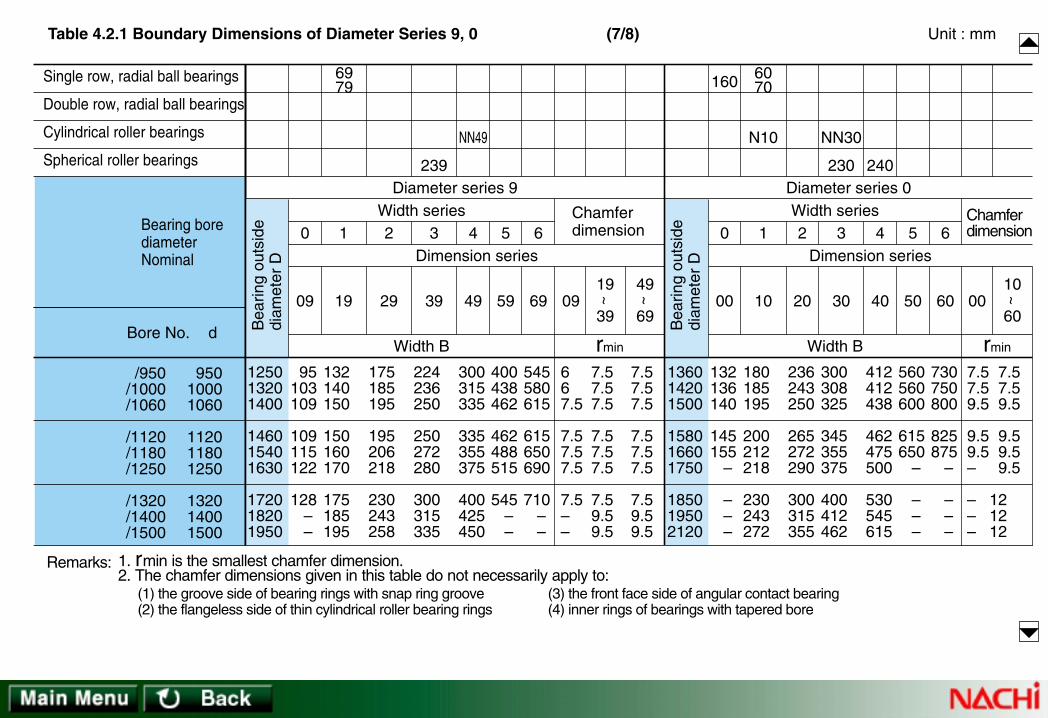
Single row, radial ball bearings
Double row, radial ball bearings
Cylindrical roller bearings
Spherical roller bearings
Bore No. d
Bearing borediameterNominal
Bea
ring
outs
ide
diam
eter
D
Bea
ring
outs
ide
diam
eter
D
Chamferdimension
Chamferdimension
Diameter series 9 Diameter series 0
Dimension series
Width series
rminWidth B
09 19 29 39 49 59 69 0919
39
~
49
69
~
0 1 2 3 4 5 6Dimension series
rminWidth B
Width series
10
60
~ 00 10 20 30 40 50 60 00
0 1 2 3 4 5 6
240230
NN30N10
6070
6979 160
239
NN49
/950 /1000 /1060
/1120 /1180 /1250
/1320 /1400 /1500
95010001060
112011801250
132014001500
125013201400
146015401630
172018201950
95103109
109115122
128– –
132140150
150160170
175185195
300315335
335355375
400425450
667.5
7.57.57.5
7.5––
7.57.57.5
7.57.57.5
7.59.59.5
7.57.57.5
7.57.57.5
7.59.59.5
136014201500
158016601750
185019502120
132136140
145155
–
– – –
7.57.59.5
9.59.5–
–––
7.57.59.5
9.59.59.5
121212
175185195
195206218
230243258
224236250
250272280
300315335
400438462
462488515
545– –
545580615
615650690
710– –
180185195
200212218
230243272
236243250
265272290
300315355
300308325
345355375
400412462
412412438
462475500
530545615
560560600
615650
–
– – –
730750800
825875
–
– – –
Remarks: 1. rmin is the smallest chamfer dimension.2. The chamfer dimensions given in this table do not necessarily apply to:
(1) the groove side of bearing rings with snap ring groove(2) the flangeless side of thin cylindrical roller bearing rings
(3) the front face side of angular contact bearing(4) inner rings of bearings with tapered bore
Table 4.2.1 Boundary Dimensions of Diameter Series 9, 0 (7/8) Unit : mm
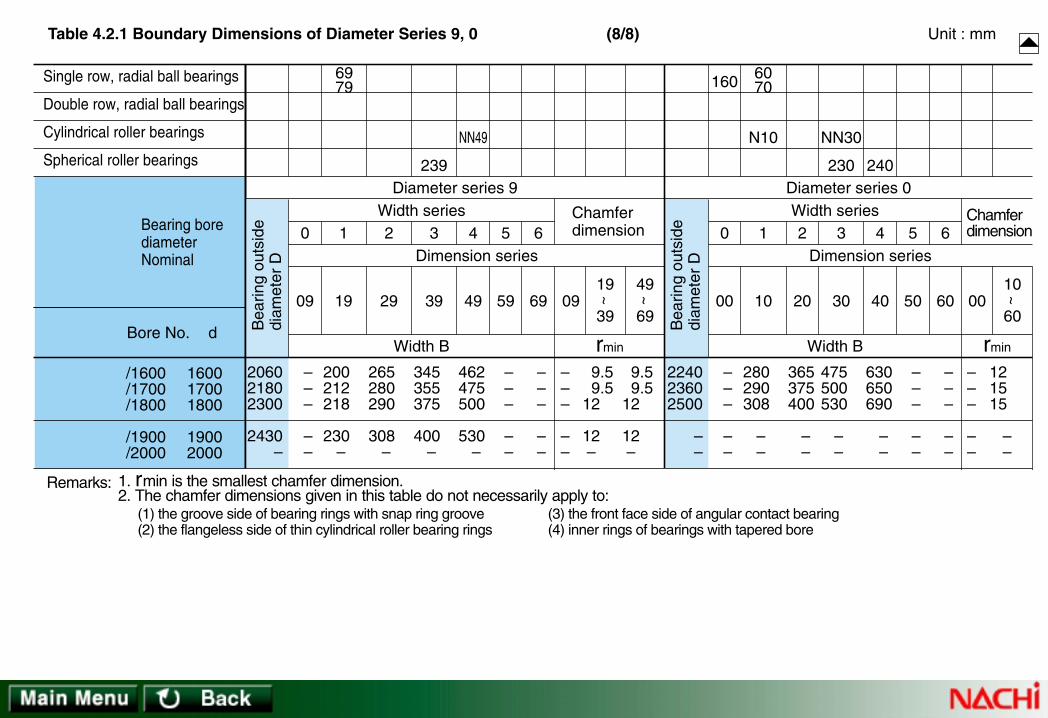
Single row, radial ball bearings
Double row, radial ball bearings
Cylindrical roller bearings
Spherical roller bearings
Bore No. d
Bearing borediameterNominal
Bea
ring
outs
ide
diam
eter
D
Bea
ring
outs
ide
diam
eter
D
Chamferdimension
Chamferdimension
Diameter series 9 Diameter series 0
Dimension series
Width series
rminWidth B
09 19 29 39 49 59 69 0919
39
~
49
69
~
0 1 2 3 4 5 6Dimension series
rminWidth B
Width series
10
60
~ 00 10 20 30 40 50 60 00
0 1 2 3 4 5 6
240230
NN30N10
6070
6979 160
239
NN49
/1600 /1700 /1800
/1900 /2000
160017001800
19002000
206021802300
2430–
– – –
– –
200212218
230–
462475500
530–
–––
––
9.59.5
12
12–
9.59.5
12
12–
224023602500
––
– – –
– –
–––
––
121515
– –
265280290
308–
345355375
400–
– – –
– –
– – –
– –
280290308
– –
365375400
– –
475500530
– –
630650690
– –
– – –
– –
– – –
– –
Remarks: 1. rmin is the smallest chamfer dimension.2. The chamfer dimensions given in this table do not necessarily apply to:
(1) the groove side of bearing rings with snap ring groove(2) the flangeless side of thin cylindrical roller bearing rings
(3) the front face side of angular contact bearing(4) inner rings of bearings with tapered bore
Table 4.2.1 Boundary Dimensions of Diameter Series 9, 0 (8/8) Unit : mm
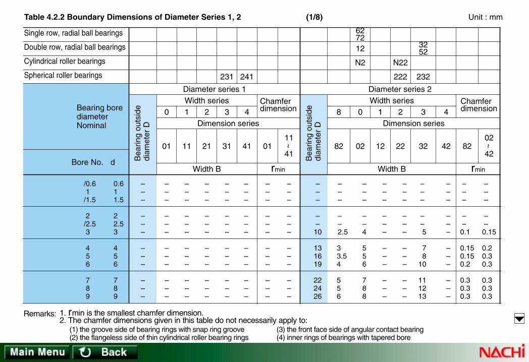
Single row, radial ball bearings
Double row, radial ball bearings
Cylindrical roller bearings
Spherical roller bearings
d
01
0
Diameter series 1Width series
Dimension series
Width B
11
1
21
2
31
3
41
4
0111
41
~ 82
8
02
0
12
1
22
2
32
3
42
4
8202
42
~
rmin
Diameter series 2Width series
Width B
Dimension series
3252
N22
222
627212
N2
232241231
Bearing borediameterNominal
Bore No. Bea
ring
outs
ide
diam
eter
D
Bea
ring
outs
ide
diam
eter
D
Chamferdimension
Chamferdimension
rmin
/0.61 /1.5
2 /2.53
4 5 6
7 8 9
0.61 1.5
2 2.53
4 5 6
7 8 9
–––
–––
–––
–––
–––
–––
–––
–––
–––
–––
–––
–––
–––
–––
–––
–––
–––
–––
–––
–––
–––
–––
–––
–––
–––
–––
–––
–––
–––
–––
–––
–––
– – –
– –
10
131619
222426
– – –
– –
2.5
3 3.54
556
–––
––4
556
788
–––
–––
–––
–––
–––
–––
–––
–––
– – –
– – 5
7 810
111213
–––
–––
–––
–––
– – –
– –0.1
0.150.150.2
0.30.30.3
– – –
– –0.15
0.20.30.3
0.30.30.3
Remarks: 1. rmin is the smallest chamfer dimension.2. The chamfer dimensions given in this table do not necessarily apply to:
(1) the groove side of bearing rings with snap ring groove(2) the flangeless side of thin cylindrical roller bearing rings
(3) the front face side of angular contact bearing(4) inner rings of bearings with tapered bore
Table 4.2.2 Boundary Dimensions of Diameter Series 1, 2 (1/8) Unit : mm

Single row, radial ball bearings
Double row, radial ball bearings
Cylindrical roller bearings
Spherical roller bearings
d
01
0
Diameter series 1Width series
Dimension series
Width B
11
1
21
2
31
3
41
4
0111
41
~ 82
8
02
0
12
1
22
2
32
3
42
4
8202
42
~
rmin
Diameter series 2Width series
Width B
Dimension series
3252
N22
222
627212
N2
232241231
Bearing borediameterNominal
Bore No. Bea
ring
outs
ide
diam
eter
D
Bea
ring
outs
ide
diam
eter
D
Chamferdimension
Chamferdimension
rmin
00 01 02
03 04 /22
05 /28 06
/32 07 08
10 12 15
17 20 22
25 28 30
32 35 40
–––
–––
–––
–––
–––
–––
–––
–––
–––
–––
–––
–––
–––
–––
–––
–––
–––
–––
–––
–––
–––
–––
–––
–––
–––
–––
–––
–––
–––
–––
–––
–––
303235
404750
525862
657280
778
899
101010
111213
91011
121414
151616
171718
–––
–––
–––
–––
141414
161818
181920
212323
14.315.915.9
17.520.620.6
20.62323.8
252730.2
––
20
222727
273032
333740
0.30.30.3
0.30.30.3
0.30.60.6
0.60.60.6
0.60.60.6
0.611
111
11.11.1
Remarks: 1. rmin is the smallest chamfer dimension.2. The chamfer dimensions given in this table do not necessarily apply to:
(1) the groove side of bearing rings with snap ring groove(2) the flangeless side of thin cylindrical roller bearing rings
(3) the front face side of angular contact bearing(4) inner rings of bearings with tapered bore
Table 4.2.2 Boundary Dimensions of Diameter Series 1, 2 (2/8) Unit : mm

Single row, radial ball bearings
Double row, radial ball bearings
Cylindrical roller bearings
Spherical roller bearings
d
01
0
Diameter series 1Width series
Dimension series
Width B
11
1
21
2
31
3
41
4
0111
41
~ 82
8
02
0
12
1
22
2
32
3
42
4
8202
42
~
rmin
Diameter series 2Width series
Width B
Dimension series
3252
N22
222
627212
N2
232241231
Bearing borediameterNominal
Bore No. Bea
ring
outs
ide
diam
eter
D
Bea
ring
outs
ide
diam
eter
D
Chamferdimension
Chamferdimension
rmin
09 10 11
12 13 14
15 16 17
18 19 20
45 50 55
60 65 70
75 80 85
90 95
100
–––
–––
–––
150 160 165
–––
–––
–––
––
21
–––
–––
–––
––
30
–––
–––
–––
––
39
–––
–––
–––
––
52
–––
–––
–––
60 65 65
–––
–––
–––
––
1.1
–––
–––
–––
2 2 2
8590
100
110120125
130140150
160170180
131314
161818
181921
222425
192021
222324
252628
303234
–––
–––
–––
–––
232325
283131
313336
404346
30.230.233.3
36.538.139.7
41.344.449.2
52.455.660.3
404045
505656
566065
697580
0.60.60.6
111
111.1
1.11.11.5
1.11.11.5
1.51.51.5
1.522
22.12.1
Remarks: 1. rmin is the smallest chamfer dimension.2. The chamfer dimensions given in this table do not necessarily apply to:
(1) the groove side of bearing rings with snap ring groove(2) the flangeless side of thin cylindrical roller bearing rings
(3) the front face side of angular contact bearing(4) inner rings of bearings with tapered bore
Table 4.2.2 Boundary Dimensions of Diameter Series 1, 2 (3/8) Unit : mm

Single row, radial ball bearings
Double row, radial ball bearings
Cylindrical roller bearings
Spherical roller bearings
d
01
0
Diameter series 1Width series
Dimension series
Width B
11
1
21
2
31
3
41
4
0111
41
~ 82
8
02
0
12
1
22
2
32
3
42
4
8202
42
~
rmin
Diameter series 2Width series
Width B
Dimension series
3252
N22
222
627212
N2
232241231
Bearing borediameterNominal
Bore No. Bea
ring
outs
ide
diam
eter
D
Bea
ring
outs
ide
diam
eter
D
Chamferdimension
Chamferdimension
rmin
21 22 24
26 28 30
32 34 36
38 40 44
105110120
130140150
160170180
190200220
175180200
210225250
270280300
320340370
222225
252731
343437
424448
1.11.11.5
1.51.52
222.1
333
222
22.12.1
2.12.13
334
190200215
230250270
290310320
340360400
2728
–
– – –
– – –
– – –
363840
404245
485252
555865
––
42
465054
586262
657078
505358
646873
808686
9298
108
65.169.876
808896
104 110 112
120 128 144
859095
100109118
128140140
150160180
1.51.5 –
– – –
– – –
– – –
2.12.12.1
333
344
444
333338
384046
515156
606569
424248
485060
666672
788288
565662
646880
868896
104112120
696980
8085
100
109109118
128140150
Remarks: 1. rmin is the smallest chamfer dimension.2. The chamfer dimensions given in this table do not necessarily apply to:
(1) the groove side of bearing rings with snap ring groove(2) the flangeless side of thin cylindrical roller bearing rings
(3) the front face side of angular contact bearing(4) inner rings of bearings with tapered bore
Table 4.2.2 Boundary Dimensions of Diameter Series 1, 2 (4/8) Unit : mm

Single row, radial ball bearings
Double row, radial ball bearings
Cylindrical roller bearings
Spherical roller bearings
d
01
0
Diameter series 1Width series
Dimension series
Width B
11
1
21
2
31
3
41
4
0111
41
~ 82
8
02
0
12
1
22
2
32
3
42
4
8202
42
~
rmin
Diameter series 2Width series
Width B
Dimension series
3252
N22
222
627212
N2
232241231
Bearing borediameterNominal
Bore No. Bea
ring
outs
ide
diam
eter
D
Bea
ring
outs
ide
diam
eter
D
Chamferdimension
Chamferdimension
rmin
48 52 56
60 64 68
72 76 80
84 88 92
240260280
300320340
360380400
420440460
400440460
500540580
600620650
700720760
505757
637178
787880
888895
444
555
556
666
445
555
556
667.5
440480500
540580620
650680720
760790830
– – –
– – –
– – –
– – –
728080
859292
9595
103
109112118
859090
98105118
122132140
150155165
120130130
140150165
170175185
195200212
160 174 176
192 208 224
232 240 256
272 280 296
200218218
243258280
290300315
335345365
– – –
– – –
– – –
– – –
455
556
666
7.57.57.5
748282
90100106
106106112
122122132
95106106
118128140
140140145
165165175
128144146
160176190
192194200
224226240
160180180
200218243
243243250
280280300
Remarks: 1. rmin is the smallest chamfer dimension.2. The chamfer dimensions given in this table do not necessarily apply to:
(1) the groove side of bearing rings with snap ring groove(2) the flangeless side of thin cylindrical roller bearing rings
(3) the front face side of angular contact bearing(4) inner rings of bearings with tapered bore
Table 4.2.2 Boundary Dimensions of Diameter Series 1, 2 (5/8) Unit : mm

Single row, radial ball bearings
Double row, radial ball bearings
Cylindrical roller bearings
Spherical roller bearings
d
01
0
Diameter series 1Width series
Dimension series
Width B
11
1
21
2
31
3
41
4
0111
41
~ 82
8
02
0
12
1
22
2
32
3
42
4
8202
42
~
rmin
Diameter series 2Width series
Width B
Dimension series
3252
N22
222
627212
N2
232241231
Bearing borediameterNominal
Bore No. Bea
ring
outs
ide
diam
eter
D
Bea
ring
outs
ide
diam
eter
D
Chamferdimension
Chamferdimension
rmin
96 /500 /530
/560 /600 /630
/670 /710 /750
/800 /850 /900
480500530
560600630
670710750
800850900
790830870
920980
1030
109011501220
128013601420
100106109
115122128
136140150
155165165
67.57.5
7.57.57.5
7.59.59.5
9.51212
7.57.57.5
7.57.57.5
7.59.59.5
9.51212
870920980
103010901150
122012801360
142015001580
– – –
– – –
– – –
– – –
125136145
150155165
175180195
200206218
170185200
206212230
243250265
272280300
224243258
272280300
315325345
355375388
310 336 355
365 388 412
438 450 475
488 515 515
388412450
475488515
545560615
615650670
– – –
– – –
– – –
– – –
7.57.59.5
9.59.5
12
121215
151515
136145150
160170175
185195206
212224230
180190195
206218230
243250272
272290300
248264272
280300315
336345365
375400412
308325335
355375400
412438475
475500515
Remarks: 1. rmin is the smallest chamfer dimension.2. The chamfer dimensions given in this table do not necessarily apply to:
(1) the groove side of bearing rings with snap ring groove(2) the flangeless side of thin cylindrical roller bearing rings
(3) the front face side of angular contact bearing(4) inner rings of bearings with tapered bore
Table 4.2.2 Boundary Dimensions of Diameter Series 1, 2 (6/8) Unit : mm

Single row, radial ball bearings
Double row, radial ball bearings
Cylindrical roller bearings
Spherical roller bearings
d
01
0
Diameter series 1Width series
Dimension series
Width B
11
1
21
2
31
3
41
4
0111
41
~ 82
8
02
0
12
1
22
2
32
3
42
4
8202
42
~
rmin
Diameter series 2Width series
Width B
Dimension series
3252
N22
222
627212
N2
232241231
Bearing borediameterNominal
Bore No. Bea
ring
outs
ide
diam
eter
D
Bea
ring
outs
ide
diam
eter
D
Chamferdimension
Chamferdimension
rmin
/950 /1000 /1060
/1120 /1180 /1250
/1320 /1400 /1500
95010001060
112011801250
132014001500
150015801660
175018501950
206021802300
175185190
–––
–––
121212
– – –
– – –
121215
151515
151919
16601750
–
– – –
– – –
– – –
– – –
– – –
230243
–
–––
–––
315330
–
–––
–––
412425
–
–––
–––
530 560
–
– – –
– – –
710750
–
–––
–––
– – –
– – –
– – –
1515 –
– – –
– – –
243258265
280290308
325345355
315335345
365388400
425450462
438462475
475500530
560580600
545580600
630670710
750775800
Remarks: 1. rmin is the smallest chamfer dimension.2. The chamfer dimensions given in this table do not necessarily apply to:
(1) the groove side of bearing rings with snap ring groove(2) the flangeless side of thin cylindrical roller bearing rings
(3) the front face side of angular contact bearing(4) inner rings of bearings with tapered bore
Table 4.2.2 Boundary Dimensions of Diameter Series 1, 2 (7/8) Unit : mm

Single row, radial ball bearings
Double row, radial ball bearings
Cylindrical roller bearings
Spherical roller bearings
d
01
0
Diameter series 1Width series
Dimension series
Width B
11
1
21
2
31
3
41
4
0111
41
~ 82
8
02
0
12
1
22
2
32
3
42
4
8202
42
~
rmin
Diameter series 2Width series
Width B
Dimension series
3252
N22
222
627212
N2
232241231
Bearing borediameterNominal
Bore No. Bea
ring
outs
ide
diam
eter
D
Bea
ring
outs
ide
diam
eter
D
Chamferdimension
Chamferdimension
rmin
/1600 /1700 /1800
/1900 /2000
160017001800
19002000
–––
––
–––
––
– – –
– –
– – –
– –
– – –
– –
– – –
– –
–––
––
–––
––
–––
––
– – –
– –
–––
––
– – –
– –
– – –
– –
–––
––
–––
––
–––
––
–––
––
Remarks: 1. rmin is the smallest chamfer dimension.2. The chamfer dimensions given in this table do not necessarily apply to:
(1) the groove side of bearing rings with snap ring groove(2) the flangeless side of thin cylindrical roller bearing rings
(3) the front face side of angular contact bearing(4) inner rings of bearings with tapered bore
Table 4.2.1 Boundary Dimensions of Diameter Series 7, 8 (8/8) Unit : mm

Single row, radial ball bearings
Double row, radial ball bearings
Cylindrical roller bearings
Spherical roller bearings
rmin
03
33
~ 8383
8
03
0
13
1
23
2
33
3
rmin
04
24
~ 04 24
0 2
Diameter series 4Width series
Dimension series
Width B
Diameter series 3Width series
Width B
Dimension series
N4
3353
N23
223
637313
N3
213
Bea
ring
outs
ide
diam
eter
D
Bea
ring
outs
ide
diam
eter
D
Chamferdimension
Chamferdimension
d
Bearing borediameterNominal
Bore No.
– – –
– – 13
161922
262830
–––
–––
–––
–––
–––
––5
567
99
10
–––
–––
–––
–––
–––
–––
––
11
131314
–––
–––
–––
–––
–––
––0.2
0.30.30.3
0.30.30.6
– – –
– – –
– – –
– 3032
–––
–––
–––
–1011
–––
–––
–––
–1415
–––
–––
–––
–0.60.6
– – –
– – 7
91013
151516
/0.61 /1.5
2 /2.53
4 5 6
7 8 9
0.61 1.5
2 2.53
4 5 6
7 8 9
Remarks: 1. rmin is the smallest chamfer dimension.2. The chamfer dimensions given in this table do not necessarily apply to:
(1) the groove side of bearing rings with snap ring groove(2) the flangeless side of thin cylindrical roller bearing rings
(3) the front face side of angular contact bearing(4) inner rings of bearings with tapered bore
Table 4.2.2 Boundary Dimensions of Diameter Series 3, 4 (1/8) Unit : mm

Single row, radial ball bearings
Double row, radial ball bearings
Cylindrical roller bearings
Spherical roller bearings
rmin
03
33
~ 8383
8
03
0
13
1
23
2
33
3
rmin
04
24
~ 04 24
0 2
Diameter series 4Width series
Dimension series
Width B
Diameter series 3Width series
Width B
Dimension series
N4
3353
N23
223
637313
N3
213
Bea
ring
outs
ide
diam
eter
D
Bea
ring
outs
ide
diam
eter
D
Chamferdimension
Chamferdimension
d
Bearing borediameterNominal
Bore No.
353742
475256
626872
758090
999
101011
121313
141416
111213
141516
171819
202123
–––
–––
–––
–––
171717
192121
242427
283133
0.30.30.3
0.60.60.6
0.60.60.6
0.60.61
0.611
11.11.1
1.11.11.1
1.11.51.5
374252
6272–
80–
90
–100110
121315
1719–
21–
23
–2527
161924
2933–
36–
40
–4346
0.611.1
1.11.1–
1.5–1.5
–1.52
191919
22.222.225
25.43030.2
3234.936.5
00 01 02
03 04 /22
05 /28 06
/32 07 08
10 12 15
17 20 22
25 28 30
32 35 40
Remarks: 1. rmin is the smallest chamfer dimension.2. The chamfer dimensions given in this table do not necessarily apply to:
(1) the groove side of bearing rings with snap ring groove(2) the flangeless side of thin cylindrical roller bearing rings
(3) the front face side of angular contact bearing(4) inner rings of bearings with tapered bore
Table 4.2.2 Boundary Dimensions of Diameter Series 3, 4 (2/8) Unit : mm

Single row, radial ball bearings
Double row, radial ball bearings
Cylindrical roller bearings
Spherical roller bearings
rmin
03
33
~ 8383
8
03
0
13
1
23
2
33
3
rmin
04
24
~ 04 24
0 2
Diameter series 4Width series
Dimension series
Width B
Diameter series 3Width series
Width B
Dimension series
N4
3353
N23
223
637313
N3
213
Bea
ring
outs
ide
diam
eter
D
Bea
ring
outs
ide
diam
eter
D
Chamferdimension
Chamferdimension
d
Bearing borediameterNominal
Bore No.
100110120
130140150
160170180
190200215
171921
222425
272830
303336
252729
313335
373941
434547
–––
–––
–––
––
51
364043
464851
555860
646773
111.1
1.11.11.5
1.51.52
222.1
1.522
2.12.12.1
2.12.13
333
120130140
150160180
190200210
225240250
293133
353742
454852
545558
505357
606474
778086
909598
22.12.1
2.12.13
334
444
39.744.449.2
5458.763.5
68.368.373
7377.882.6
09 10 11
12 13 14
15 16 17
18 19 20
45 50 55
60 65 70
75 80 85
90 95
100
Remarks: 1. rmin is the smallest chamfer dimension.2. The chamfer dimensions given in this table do not necessarily apply to:
(1) the groove side of bearing rings with snap ring groove(2) the flangeless side of thin cylindrical roller bearing rings
(3) the front face side of angular contact bearing(4) inner rings of bearings with tapered bore
Table 4.2.2 Boundary Dimensions of Diameter Series 3, 4 (3/8) Unit : mm

Single row, radial ball bearings
Double row, radial ball bearings
Cylindrical roller bearings
Spherical roller bearings
rmin
03
33
~ 8383
8
03
0
13
1
23
2
33
3
rmin
04
24
~ 04 24
0 2
Diameter series 4Width series
Dimension series
Width B
Diameter series 3Width series
Width B
Dimension series
N4
3353
N23
223
637313
N3
213
Bea
ring
outs
ide
diam
eter
D
Bea
ring
outs
ide
diam
eter
D
Chamferdimension
Chamferdimension
d
Bearing borediameterNominal
Bore No.
225240260
280300320
340360380
400420460
374244
4850–
–––
–––
495055
586265
687275
788088
535762
667075
798488
9297
106
778086
93102108
114120126
132138145
87.3 92.1
106
112118128
136140150
155165180
2.133
34–
–––
–––
333
444
444
555
260280310
340360380
400420440
460480540
606572
788285
889295
98102115
100108118
128132138
142145150
155160180
445
555
556
666
21 22 24
26 28 30
32 34 36
38 40 44
105110120
130140150
160170180
190200220
Remarks: 1. rmin is the smallest chamfer dimension.2. The chamfer dimensions given in this table do not necessarily apply to:
(1) the groove side of bearing rings with snap ring groove(2) the flangeless side of thin cylindrical roller bearing rings
(3) the front face side of angular contact bearing(4) inner rings of bearings with tapered bore
Table 4.2.2 Boundary Dimensions of Diameter Series 3, 4 (4/8) Unit : mm
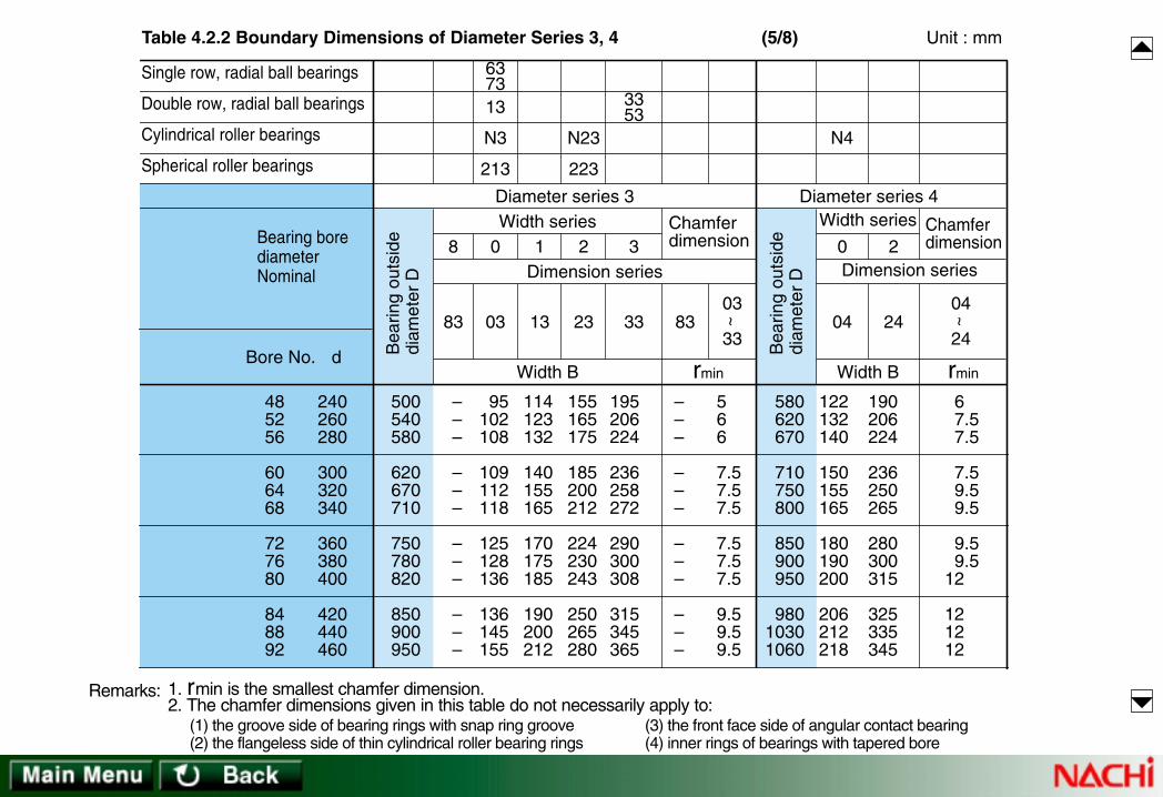
Single row, radial ball bearings
Double row, radial ball bearings
Cylindrical roller bearings
Spherical roller bearings
rmin
03
33
~ 8383
8
03
0
13
1
23
2
33
3
rmin
04
24
~ 04 24
0 2
Diameter series 4Width series
Dimension series
Width B
Diameter series 3Width series
Width B
Dimension series
N4
3353
N23
223
637313
N3
213
Bea
ring
outs
ide
diam
eter
D
Bea
ring
outs
ide
diam
eter
D
Chamferdimension
Chamferdimension
d
Bearing borediameterNominal
Bore No.
500540580
620670710
750780820
850900950
–––
–––
–––
–––
95102108
109112118
125128136
136145155
114123132
140155165
170175185
190200212
155165175
185200212
224230243
250265280
195206224
236258272
290300308
315345365
–––
–––
–––
–––
566
7.57.57.5
7.57.57.5
9.59.59.5
580620670
710750800
850900950
98010301060
122132140
150155165
180190200
206212218
190206224
236250265
280300315
325335345
67.57.5
7.59.59.5
9.59.5
12
121212
48 52 56
60 64 68
72 76 80
84 88 92
240260280
300320340
360380400
420440460
Remarks: 1. rmin is the smallest chamfer dimension.2. The chamfer dimensions given in this table do not necessarily apply to:
(1) the groove side of bearing rings with snap ring groove(2) the flangeless side of thin cylindrical roller bearing rings
(3) the front face side of angular contact bearing(4) inner rings of bearings with tapered bore
Table 4.2.2 Boundary Dimensions of Diameter Series 3, 4 (5/8) Unit : mm

Single row, radial ball bearings
Double row, radial ball bearings
Cylindrical roller bearings
Spherical roller bearings
rmin
03
33
~ 8383
8
03
0
13
1
23
2
33
3
rmin
04
24
~ 04 24
0 2
Diameter series 4Width series
Dimension series
Width B
Diameter series 3Width series
Width B
Dimension series
N4
3353
N23
223
637313
N3
213
Bea
ring
outs
ide
diam
eter
D
Bea
ring
outs
ide
diam
eter
D
Chamferdimension
Chamferdimension
d
Bearing borediameterNominal
Bore No.
98010301090
115012201280
136014201500
160017001780
–––
–––
–––
–––
160170180
190200206
218224236
258272280
218230243
258272280
300308325
355375388
290300325
335355375
400412438
462488500
375388412
438462488
515530560
600630650
–––
–––
–––
–––
9.51212
121515
151515
151919
112011501220
128013601420
1500– –
– – –
230236250
258272280
290––
–––
365375400
412438450
475––
–––
151515
151515
15––
–––
96 /500 /530
/560 /600 /630
/670 /710 /750
/800 /850 /900
480500530
560600630
670710750
800850900
Remarks: 1. rmin is the smallest chamfer dimension.2. The chamfer dimensions given in this table do not necessarily apply to:
(1) the groove side of bearing rings with snap ring groove(2) the flangeless side of thin cylindrical roller bearing rings
(3) the front face side of angular contact bearing(4) inner rings of bearings with tapered bore
Table 4.2.2 Boundary Dimensions of Diameter Series 3, 4 (6/8) Unit : mm

Single row, radial ball bearings
Double row, radial ball bearings
Cylindrical roller bearings
Spherical roller bearings
rmin
03
33
~ 8383
8
03
0
13
1
23
2
33
3
rmin
04
24
~ 04 24
0 2
Diameter series 4Width series
Dimension series
Width B
Diameter series 3Width series
Width B
Dimension series
N4
3353
N23
223
637313
N3
213
Bea
ring
outs
ide
diam
eter
D
Bea
ring
outs
ide
diam
eter
D
Chamferdimension
Chamferdimension
d
Bearing borediameterNominal
Bore No.
18501950
–
– – –
– – –
–––
–––
–––
290300
–
–––
–––
400412
–
–––
–––
515545
–
–––
–––
670710
–
–––
–––
–––
–––
–––
1919–
–––
–––
– – –
– – –
– – –
–––
–––
–––
–––
–––
–––
–––
–––
–––
/950 /1000 /1060
/1120 /1180 /1250
/1320 /1400 /1500
95010001060
112011801250
132014001500
Remarks: 1. rmin is the smallest chamfer dimension.2. The chamfer dimensions given in this table do not necessarily apply to:
(1) the groove side of bearing rings with snap ring groove(2) the flangeless side of thin cylindrical roller bearing rings
(3) the front face side of angular contact bearing(4) inner rings of bearings with tapered bore
Table 4.2.2 Boundary Dimensions of Diameter Series 3, 4 (7/8) Unit : mm

Single row, radial ball bearings
Double row, radial ball bearings
Cylindrical roller bearings
Spherical roller bearings
rmin
03
33
~ 8383
8
03
0
13
1
23
2
33
3
rmin
04
24
~ 04 24
0 2
Diameter series 4Width series
Dimension series
Width B
Diameter series 3Width series
Width B
Dimension series
N4
3353
N23
223
637313
N3
213
Bea
ring
outs
ide
diam
eter
D
Bea
ring
outs
ide
diam
eter
D
Chamferdimension
Chamferdimension
d
Bearing borediameterNominal
Bore No.
– – –
– –
–––
––
–––
––
–––
––
–––
––
–––
––
–––
––
–––
––
– – –
– –
–––
––
–––
––
–––
––
/1600 /1700 /1800
/1900 /2000
160017001800
19002000
Remarks: 1. rmin is the smallest chamfer dimension.2. The chamfer dimensions given in this table do not necessarily apply to:
(1) the groove side of bearing rings with snap ring groove(2) the flangeless side of thin cylindrical roller bearing rings
(3) the front face side of angular contact bearing(4) inner rings of bearings with tapered bore
Table 4.2.2 Boundary Dimensions of Diameter Series 3, 4 (8/8) Unit : mm

––
37
404245
475255
626872
808590
––12
121212
121514
151515
171717
–– 9
9 9 9
91011.5
121212
141414
––12
121212
121414
151515
171717
––0.3
0.30.30.3
0.30.60.6
0.60.60.6
111
––0.3
0.30.30.3
0.30.60.6
0.60.60.6
111
––
42
444752
555862
687580
9095
100
––
15
151516
171718
192020
232323
––12
11.511.512
131314
14.515.515.5
17.517.517.5
––
15
151516
171718
192020
232323
–––
–17–
20–
21
222424
272727
–––
–17–
20–
21
222424
272727
–––
–14–
16–17
181919
212121
––0.6
0.60.61
111
111
1.51.51.5
––0.6
0.60.61
111
111
1.51.51.5
–––
–––
–––
262626
303034
–––
–––
–––
262626
303034
–––
–––
–––
20.520.520
232326.5
–––
–––
–––
758085
95100110
–––
–––
–––
1.51.51.5
1.51.51.5
–––
–––
–––
1.51.51.5
1.51.51.5
020304
/2205/28
06/3207
080910
111213
151720
222528
303235
404550
556065
dBoreNo.
Bearing borediameterNominal
Tapered rollerbearing
D
Outsidediameter
Outsidediameter
Outsidediameter
B C Innerring
Outerring
T D B C T B C T D B C Trmin
Innerring
Outerring
rminInnerring
Outerring
rmin
Chamferdimension
Chamferdimension
ChamferdimensionWidth series 2
Diameter series 9
329
Width series 2
320
Width series 3
330
Diameter series 0
Width series 3
331
Diameter series 1
Table 4.3.1 Boundary Dimensions of Tapered Roller Bearings
1. rmin is the smallest chamfer dimension.2. Dimensions B, C, T of 32000 and 32200 series bearings without prefix E and suffix J listed on
the pages from D84 to D87 arediffer from the above dimensions.
Note: (1) To be applied to 30300D series.
Remarks:
Unit : mm(1/3)

100105110
120125130
140145150
165180190
210220230
202020
232323
252525
293232
383838
161616
181818
202020
232525
303030
202020
232323
252525
293232
383838
111
1.51.51.5
1.51.51.5
1.522
2.52.52.5
111
1.51.51.5
1.51.51.5
1.51.51.5
222
110115125
130140145
150160170
180200210
225240260
252529
293232
323538
384545
485157
191922
222424
242629
293434
363843
252529
293232
323538
384545
485157
313136
363939
394347
485556
59––
313136
363939
394347
485556
59––
25.525.529.5
29.532.532.5
32.53437
384344
46––
1.51.51.5
1.522
22.52.5
2.52.52.5
333
1.51.51.5
1.51.51.5
1.522
222
2.52.52.5
373737
414549
525656
62––
–––
373737
414549
525656
62––
–––
292929
323538
404443
48––
–––
120125130
140150160
165175180
200––
–––
222
2.52.52.5
2.52.52.5
2.5––
–––
1.51.51.5
222
222
2––
–––
141516
171819
202122
242628
303234
707580
859095
100105110
120130140
150160170
dBoreNo.
Bearing borediameterNominal
Tapered rollerbearing
D
Outsidediameter
Outsidediameter
Outsidediameter
B C Innerring
Outerring
T D B C T B C T D B C Trmin
Innerring
Outerring
rminInnerring
Outerring
rmin
Chamferdimension
Chamferdimension
ChamferdimensionWidth series 2
Diameter series 9
329
Width series 2
320
Width series 3
330
Diameter series 0
Width series 3
331
Diameter series 1
Table 4.3.1 Boundary Dimensions of Tapered Roller Bearings
1. rmin is the smallest chamfer dimension.2. Dimensions B, C, T of 32000 and 32200 series bearings without prefix E and suffix J listed on
the pages from D84 to D87 arediffer from the above dimensions.
Note: (1) To be applied to 30300D series.
Remarks:
Unit : mm(2/3)

250260280
300320360
380420440
460480
454551
515163.5
63.57676
7676
343439
393948
485757
5757
454551
515163.5
63.57676
7676
2.52.53
333
344
44
222.5
2.52.52.5
2.533
33
280290310
340360400
420460480
––
646470
767687
87100100
––
484853
575765
657474
––
646470
767687
87100100
––
–––
–––
–––
––
–––
–––
–––
––
–––
–––
–––
––
333
445
555
––
2.52.52.5
334
444
––
–––
–––
–––
––
–––
–––
–––
––
–––
–––
–––
––
–––
–––
–––
––
–––
–––
–––
––
–––
–––
–––
––
363840
444852
566064
6872
180190200
220240260
280300320
340360
dBoreNo.
Bearing borediameterNominal
Tapered rollerbearing
D
Outsidediameter
Outsidediameter
Outsidediameter
B C Innerring
Outerring
T D B C T B C T D B C Trmin
Innerring
Outerring
rminInnerring
Outerring
rmin
Chamferdimension
Chamferdimension
ChamferdimensionWidth series 2
Diameter series 9
329
Width series 2
320
Width series 3
330
Diameter series 0
Width series 3
331
Diameter series 1
Table 4.3.1 Boundary Dimensions of Tapered Roller Bearings
1. rmin is the smallest chamfer dimension.2. Dimensions B, C, T of 32000 and 32200 series bearings without prefix E and suffix J listed on
the pages from D84 to D87 arediffer from the above dimensions.
Note: (1) To be applied to 30300D series.
Remarks:
Unit : mm(3/3)

–1618
–20–
232325
273033
353739
–1921
–24
–
272831
333640
434648
111.5
–1.5–
1.51.51.5
1.51.52
22.52.5
111.5
–1.5–
1.51.52
222.5
2.533
– – –
– – –
– – –
– – –
– – –
–––
–––
–––
–––
–––
–––
–––
–––
–––
–––
–––
–13–
14–
15
171819
212223
111213
–15–
16–
18
202223
252628
131415
–17–
19–
21
232527
293133
424752
–62–
727580
90100110
120130140
–11
–11
111.5
1.51.51.5
1.51.51.5
–11
–11
111.5
1.51.51.5
222
–––
–2224
252628
323232
353841
– – –
–1819
19.520.522
252524.5
272932
–––
–2224
252628
323232
353841
–1415
–1616
171719
191919
212427
–1618
–1819
2026.523
232323
252831
–13.2515.25
–16.25 –
17.2518.2518.25
19.7520.7521.75
22.7523.7524.75
–1112
–13–
141515
161617
181920
–1214
–15–
161717
181920
212223
–4047
–5258
626572
808590
100110120
–17.2519.25
–19.2520.25
21.252224.25
24.7524.7524.75
26.7529.7532.75
14.2515.2516.25
–18.25 –
20.75 –22.75
25.2527.2529.25
31.533.536
–20.2522.25
–25.25 –
28.7529.7532.75
35.2538.2542.25
45.548.551
020304
/2205/28
06/3207
080910
111213
151720
222528
303235
404550
556065
dBoreNo.
Bearing borediameterNominal
Tapered rollerbearing
Outsidediameter
Outsidediameter
D B C T B C T B C T D B C C( 1 ) T B C T C TBInnerring
Outerring
rminInnerring
Outerring
rmin
Chamferdimension
ChamferdimensionWidth series 0
302
Width series 2
322
Diameter series 2
Width series 3
332
Width series 0
303
Width series 1
313
Width series 2
323
Diameter series 3
303D
Table 4.3.2 Boundary Dimensions of Tapered Roller Bearings
1. rmin is the smallest chamfer dimension.2. Dimensions B, C, T of 32000 and 32200 series bearings without prefix E and suffix J listed on
the pages from D84 to D87 arediffer from the above dimensions.
Note: (1) To be applied to 30300D series.
Remarks:
Unit : mm(1/3)

424548
495355
606365
69––
–––
515558
606467
737780
86––
–––
2.52.52.5
333
333
344
444
333
444
444
455
555
– – –
– – –
56.55863
687277
82 – –
–––
–––
515357
626670
75––
–––
–––
353638
424447
50––
252627
283032
–––
–––
–––
303133
343638
394142
464953
555862
353739
414345
474950
555862
656872
150160170
180190200
215225240
260280300
320340360
1.51.52
222.5
2.52.52.5
2.533
334
222.5
2.52.53
333
344
445
414146
495558
6368–
–––
–––
323135
374244
4852 –
– – –
– – –
414146
495558
6368–
–––
–––
272728
303437
394346
505458
606771
313133
364043
465053
586468
738086
26.2527.2528.25
30.532.534.5
373941
43.543.7545.75
495257
212222
242627
293032
343436
384043
242526
283032
343638
404042
454852
125130140
150160170
180190200
215230250
270290310
33.2533.2535.25
38.542.545.5
495356
61.567.7571.75
778491
384042.5
44.546.549.5
51.553.554.5
59.563.7567.75
727580
545861.5
63.567.571.5
77.581.584.5
90.5 – –
– – –
141516
171819
202122
242628
303234
707580
859095
100105110
120130140
150160170
dBoreNo.
Bearing borediameterNominal
Tapered rollerbearing
Outsidediameter
Outsidediameter
D B C T B C T B C T D B C C( 1 ) T B C T C TBInnerring
Outerring
rminInnerring
Outerring
rmin
Chamferdimension
ChamferdimensionWidth series 0
302
Width series 2
322
Diameter series 2
Width series 3
332
Width series 0
303
Width series 1
313
Width series 2
323
Diameter series 3
303D
Table 4.3.2 Boundary Dimensions of Tapered Roller Bearings
1. rmin is the smallest chamfer dimension.2. Dimensions B, C, T of 32000 and 32200 series bearings without prefix E and suffix J listed on
the pages from D84 to D87 arediffer from the above dimensions.
Note: (1) To be applied to 30300D series.
Remarks:
Unit : mm(2/3)

–––
–––
–––
––
–––
–––
–––
––
–––
–––
–––
––
–––
–––
–––
––
– – –
– – –
– – –
– –
–––
–––
–––
––
–––
–––
–––
––
–––
–––
–––
––
–––
–––
–––
––
–––
–––
–––
––
– – –
– – –
– – –
– –
444
–––
–––
––
555
–––
–––
––
–––
–––
–––
––
– – –
– – –
– – –
– –
–––
–––
–––
––
717582
–––
–––
––
869298
– – –
– – –
– –
576064
– – –
– – –
– –
434648
–––
–––
––
525558
–––
–––
––
320340360
– – –
– – –
– –
9197
104
– – –
– – –
– –
–––
–––
–––
––
– – –
– – –
– – –
– –
363840
444852
566064
6872
180190200
220240260
280300320
340360
dBoreNo.
Bearing borediameterNominal
Tapered rollerbearing
Outsidediameter
Outsidediameter
D B C T B C T B C T D B C C( 1 ) T B C T C TBInnerring
Outerring
rminInnerring
Outerring
rmin
Chamferdimension
ChamferdimensionWidth series 0
302
Width series 2
322
Diameter series 2
Width series 3
332
Width series 0
303
Width series 1
313
Width series 2
323
Diameter series 3
303D
Table 4.3.2 Boundary Dimensions of Tapered Roller Bearings
1. rmin is the smallest chamfer dimension.2. Dimensions B, C, T of 32000 and 32200 series bearings without prefix E and suffix J listed on
the pages from D84 to D87 arediffer from the above dimensions.
Note: (1) To be applied to 30300D series.
Remarks:
Unit : mm(3/3)
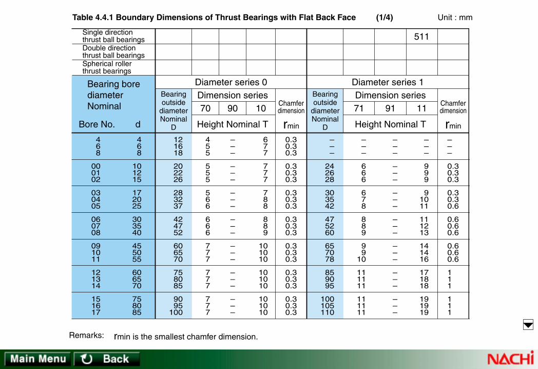
Dimension series90
Height Nominal T
70 10
Diameter series 0Dimension series
91
Height Nominal T
71 11
Diameter series 1
511
rmin
Bearingoutside
diameterNominal
D
Bearingoutside
diameterNominal
D
Chamferdimension
rmin
Chamferdimension
468
000102
030405
060708
091011
121314
151617
468
101215
172025
303540
455055
606570
758085
121618
202226
283237
424752
606570
758085
9095
100
455
555
566
666
777
777
777
–––
–––
–––
–––
–––
–––
–––
677
777
788
889
101010
101010
101010
0.30.30.3
0.30.30.3
0.30.30.3
0.30.30.3
0.30.30.3
0.30.30.3
0.30.30.3
–––
242628
303542
475260
657078
859095
100105110
–––
666
678
889
99
10
111111
111111
–––
–––
–––
–––
–––
–––
–––
–––
999
91011
111213
141416
171818
191919
–––
0.30.30.3
0.30.30.6
0.60.60.6
0.60.60.6
111
111
Single directionthrust ball bearingsDouble directionthrust ball bearingsSpherical rollerthrust bearings
Bore No. d
Bearing borediameterNominal
Table 4.4.1 Boundary Dimensions of Thrust Bearings with Flat Back Face
rmin is the smallest chamfer dimension.Remarks:
Unit : mm(1/4)

Dimension series90
Height Nominal T
70 10
Diameter series 0Dimension series
91
Height Nominal T
71 11
Diameter series 1
511
rmin
Bearingoutside
diameterNominal
D
Bearingoutside
diameterNominal
D
Chamferdimension
rmin
Chamferdimension
182022
242628
303234
363840
444852
566064
687276
90100110
120130140
150160170
180190200
220240260
280300320
340360380
105120130
140150160
170180190
200215225
250270290
310340360
380400420
799
999
999
91111
141414
141818
181818
–––
–––
–––
–––
–––
–2424
242424
101414
141414
141414
141717
222222
223030
303030
0.30.60.6
0.60.60.6
0.60.60.6
0.611
111
111
111
120135145
155170180
190200215
225240250
270300320
350380400
420440460
141616
161818
181820
202323
232727
323636
363636
–2121
212424
242427
273030
303636
424848
484848
222525
253031
313134
343737
374545
536263
646565
111
111
111.1
1.11.11.1
1.11.51.5
1.522
222
Single directionthrust ball bearingsDouble directionthrust ball bearingsSpherical rollerthrust bearings
Bore No. d
Bearing borediameterNominal
Table 4.4.1 Boundary Dimensions of Thrust Bearings with Flat Back Face
rmin is the smallest chamfer dimension.Remarks:
Unit : mm(2/4)

Dimension series90
Height Nominal T
70 10
Diameter series 0Dimension series
91
Height Nominal T
71 11
Diameter series 1
511
rmin
Bearingoutside
diameterNominal
D
Bearingoutside
diameterNominal
D
Chamferdimension
rmin
Chamferdimension
808488
9296
/500
/530/560/600
/630/670/710
/750/800/850
/900/950
/1000
/1060/1120/1180
400420440
460480500
530560600
630670710
750800850
900950
1000
106011201180
440460480
500520540
580610650
680730780
820870920
98010301090
115012201280
181818
181818
232323
232732
323232
363641
414545
242424
242424
303030
303642
424242
484854
546060
303030
303030
383838
384553
535353
636370
708080
111
111
1.11.11.1
1.11.51.5
1.51.51.5
222.1
2.12.12.1
480500540
560580600
640670710
750800850
900950
1000
106011201180
125013201400
363645
454545
505050
545863
676767
737882
8590
100
484860
606060
676767
737885
909090
95103109
115122132
656580
808080
858585
95105112
120120120
130135140
150160175
222.1
2.12.12.1
333
344
444
555
556
Single directionthrust ball bearingsDouble directionthrust ball bearingsSpherical rollerthrust bearings
Bore No. d
Bearing borediameterNominal
Table 4.4.1 Boundary Dimensions of Thrust Bearings with Flat Back Face
rmin is the smallest chamfer dimension.Remarks:
Unit : mm(3/4)

Dimension series90
Height Nominal T
70 10
Diameter series 0Dimension series
91
Height Nominal T
71 11
Diameter series 1
511
rmin
Bearingoutside
diameterNominal
D
Bearingoutside
diameterNominal
D
Chamferdimension
rmin
Chamferdimension
/1250/1320/1400
/1500/1600/1700
/1800/1900/2000
/2120/2240/2360
/2500
125013201400
150016001700
180019002000
212022402360
2500
136014401520
163017301840
195020602160
230024302550
2700
50 –
–
–––
–––
–––
–
67––
–––
–––
–––
–
859595
105105112
120130130
140150150
160
333
444
455
555
5
146015401630
175018501970
208021802300
243025702700
2850
–––
–––
–––
–––
–
–––
–––
–––
–––
–
175175180
195195212
220220236
243258265
272
666
667.5
7.57.57.5
7.59.59.5
9.5
Single directionthrust ball bearingsDouble directionthrust ball bearingsSpherical rollerthrust bearings
Bore No. d
Bearing borediameterNominal
Table 4.4.1 Boundary Dimensions of Thrust Bearings with Flat Back Face
rmin is the smallest chamfer dimension.Remarks:
Unit : mm(4/4)

72 92 12 22 22
Height Nominal T
Dimension series Chamfer dimension
rmin r1minBore d2 Height aCenter washer
Diameter series 2
512
522
292
Bearingoutside
diameterNominal
D
468
000102
030405
060708
091011
121314
151617
468
101215
172025
303540
455055
606570
758085
162022
262832
354047
526268
737890
95100105
110115125
666
778
89
10
101213
131316
161616
161618
–––
–––
–––
–––
––
21
212121
212124
899
111112
121415
161819
202225
262727
272831
–––
––
22
–2628
293436
373945
464747
474855
–––
––
10
–1520
253030
354045
505555
606570
–––
––5
–67
789
99
10
101010
101012
0.3 0.3 0.3
0.6 0.6 0.6
0.6 0.6 0.6
0.6 1 1
1 1 1
1 1 1
1 1 1
–––
––0.3
–0.30.3
0.30.30.6
0.60.60.6
0.60.61
111
Single directionthrust ball bearingsDouble directionthrust ball bearingsSpherical rollerthrust bearings
Bore No. d
Bearing borediameterNominal
Table 4.4.2 Boundary Dimensions of Thrust Bearings with Flat Back Face
rmin is the smallest chamfer dimension.Remarks:
Unit : mm(1/4)

72 92 12 22 22
Height Nominal T
Dimension series Chamfer dimension
rmin r1minBore d2 Height aCenter washer
Diameter series 2
512
522
292
Bearingoutside
diameterNominal
D
182022
242628
303234
363840
444852
566064
687276
90100110
120130140
150160170
180190200
220240260
280300320
340360380
135150160
170190200
215225240
250270280
300340360
380420440
460500520
202323
232727
292932
323636
364545
455454
546363
273030
303636
393942
424848
486060
607373
738585
353838
394546
505155
566262
637879
809595
96110112
626767
688081
899097
98109109
110––
–––
–––
758595
100110120
130140150
150160170
190––
–––
–––
141515
151818
202021
212424
24––
–––
–––
1.1 1.1 1.1
1.1 1.5 1.5
1.5 1.5 1.5
1.5 2 2
2 2.1 2.1
2.1 3 3
3 4 4
111
1.11.11.1
1.11.11.1
222
2––
–––
–––
Single directionthrust ball bearingsDouble directionthrust ball bearingsSpherical rollerthrust bearings
Bore No. d
Bearing borediameterNominal
Table 4.4.2 Boundary Dimensions of Thrust Bearings with Flat Back Face
rmin is the smallest chamfer dimension.Remarks:
Unit : mm(2/4)

72 92 12 22 22
Height Nominal T
Dimension series Chamfer dimension
rmin r1minBore d2 Height aCenter washer
Diameter series 2
512
522
292
Bearingoutside
diameterNominal
D
808488
9296
/500
/530/560/600
/630/670/710
/750/800/850
/900/950
/1000
/1060/1120/1180
400420440
460480500
530560600
630670710
750800850
900950
1000
106011201180
540580600
620650670
710750800
850900950
100010601120
118012501320
140014601520
637373
737878
828590
100103109
112118122
125136145
155––
859595
95103103
109115122
132140145
150155160
170180190
206206206
112130130
130135135
140150160
175180190
195205212
220236250
265––
–––
–––
–––
–––
–––
–––
–––
–––
–––
–––
–––
–––
–––
–––
–––
–––
–––
–––
–––
–––
–––
4 5 5
5 5 5
5 5 5
6 6 6
6 7.5 7.5
7.5 7.5 9.5
9.5 9.5 9.5
–––
–––
–––
–––
–––
–––
–––
Single directionthrust ball bearingsDouble directionthrust ball bearingsSpherical rollerthrust bearings
Bore No. d
Bearing borediameterNominal
Table 4.4.1 Boundary Dimensions of Thrust Bearings with Flat Back Face
rmin is the smallest chamfer dimension.Remarks:
Unit : mm(3/4)

72 92 12 22 22
Height Nominal T
Dimension series Chamfer dimension
rmin r1minBore d2 Height aCenter washer
Diameter series 2
512
522
292
Bearingoutside
diameterNominal
D
/1250/1320/1400
/1500/1600/1700
/1800/1900/2000
/2120/2240/2360
/2500
125013201400
150016001700
180019002000
212022402360
2500
161017001760
192020402160
2280––
–––
–
–––
–––
–––
–––
–
216228234
252264276
280––
–––
–
–––
–––
–––
–––
–
–––
–––
–––
–––
–
–––
–––
–––
–––
–
–––
–––
–––
–––
–
9.5 9.512
121515
15 – –
– – –
–
–––
–––
–––
–––
–
Single directionthrust ball bearingsDouble directionthrust ball bearingsSpherical rollerthrust bearings
Bore No. d
Bearing borediameterNominal
Table 4.4.2 Boundary Dimensions of Thrust Bearings with Flat Back Face
rmin is the smallest chamfer dimension.Remarks:
Unit : mm(4/4)

Single directionthrust ball bearingsDouble directionthrust ball bearingsSpherical rollerthrust bearings
Bore No. d
Bearing borediameterNominal 23
Height Nominal T
139373Dimension series
23Center washer
Diameter series 3
513
523
293
Bearingoutside
diameterNominal
D
Chamfer dimension
rmin r1minBore d2 Height a
202426
303237
404752
606878
8595
105
110115125
135140150
788
99
10
101212
141517
182023
232325
272729
–––
–––
–––
––
22
242730
303034
363639
111212
141415
161818
212426
283135
353640
444449
–––
–––
––
34
384449
525864
646572
797987
–––
–––
––
20
253030
354045
505555
606570
–––
–––
––8
91012
121415
151516
181819
0.6 0.6 0.6
0.6 0.6 0.6
0.6 1 1
1 1 1
1 1.1 1.1
1.1 1.1 1.1
1.5 1.5 1.5
–––
–––
––0.3
0.30.30.6
0.60.60.6
0.60.61
111
468
000102
030405
060708
091011
121314
151617
468
101215
172025
303540
455055
606570
758085
Table 4.4.3 Boundary Dimensions of Thrust Bearings with Flat Back Face
rmin is the smallest chamfer dimension.Remarks:
Unit : mm(1/4)
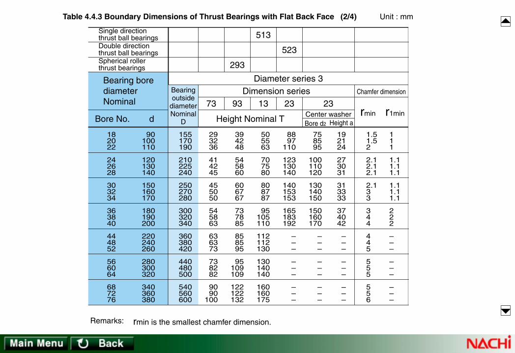
Single directionthrust ball bearingsDouble directionthrust ball bearingsSpherical rollerthrust bearings
Bore No. d
Bearing borediameterNominal 23
Height Nominal T
139373Dimension series
23Center washer
Diameter series 3
513
523
293
Bearingoutside
diameterNominal
D
Chamfer dimension
rmin r1minBore d2 Height a
155170190
210225240
250270280
300320340
360380420
440480500
540560600
293236
414245
455050
545863
636373
738282
9090
100
394248
545860
606767
737885
858595
95109109
122122132
505563
707580
808787
95105110
112112130
130140140
160160175
8897
110
123130140
140153153
165183192
–––
–––
–––
758595
100110120
130140150
150160170
–––
–––
–––
192124
273031
313333
374042
–––
–––
–––
1.5 1.5 2
2.1 2.1 2.1
2.1 3 3
3 4 4
4 4 5
5 5 5
5 5 6
111
1.11.11.1
1.11.11.1
222
–––
–––
–––
182022
242628
303234
363840
444852
566064
687276
90100110
120130140
150160170
180190200
220240260
280300320
340360380
Table 4.4.3 Boundary Dimensions of Thrust Bearings with Flat Back Face
rmin is the smallest chamfer dimension.Remarks:
Unit : mm(2/4)

Single directionthrust ball bearingsDouble directionthrust ball bearingsSpherical rollerthrust bearings
Bore No. d
Bearing borediameterNominal 23
Height Nominal T
139373Dimension series
23Center washer
Diameter series 3
513
523
293
Bearingoutside
diameterNominal
D
Chamfer dimension
rmin r1minBore d2 Height a
620650680
710730750
800850900
95010001060
112011801250
132014001460
154016301710
100103109
112112112
122132136
145150160
165170180
190200
–
–––
132140145
150150150
160175180
190200212
224230243
250272276
288306318
175180190
195195195
212224236
250258272
290300315
335355
–
–––
–––
–––
–––
–––
–––
–––
–––
–––
–––
–––
–––
–––
–––
–––
–––
–––
–––
–––
–––
–––
–––
6 6 6
6 6 6
7.5 7.5 7.5
9.5 9.5 9.5
9.5 9.512
121212
151515
–––
–––
–––
–––
–––
–––
–––
808488
9296
/500
/530/560/600
/630/670/710
/750/800/850
/900/950
/1000
/1060/1120/1180
400420440
460480500
530560600
630670710
750800850
900950
1000
106011201180
Table 4.4.3 Boundary Dimensions of Thrust Bearings with Flat Back Face
rmin is the smallest chamfer dimension.Remarks:
Unit : mm(3/4)

Single directionthrust ball bearingsDouble directionthrust ball bearingsSpherical rollerthrust bearings
Bore No. d
Bearing borediameterNominal 23
Height Nominal T
139373Dimension series
23Center washer
Diameter series 3
513
523
293
Bearingoutside
diameterNominal
D
Chamfer dimension
rmin r1minBore d2 Height a
180019002000
21402270
–
–––
–––
–
–––
–––
–––
–––
–
330348360
384402
–
–––
–––
–
–––
–––
–––
–––
–
–––
–––
–––
–––
–
–––
–––
–––
–––
–
–––
–––
–––
–––
–
151919
1919 –
– – –
– – –
–
–––
–––
–––
–––
–
/1250/1320/1400
/1500/1600/1700
/1800/1900/2000
/2120/2240/2360
/2500
125013201400
150016001700
180019002000
212022402360
2500
Table 4.4.3 Boundary Dimensions of Thrust Bearings with Flat Back Face
rmin is the smallest chamfer dimension.Remarks:
Unit : mm(4/4)

Single directionthrust ball bearingsDouble directionthrust ball bearingsSpherical rollerthrust bearings
Bore No. d
Bearing borediameterNominal
Chamferdimension
rmin95
Dimensionseries
HeightNominal
T
Diameter series 5Bearingoutside
diameterNominal
DHeight Nominal T
9474 2414Dimension series
24Center washer
Diameter series 4
514
524
294
Bearingoutside
diameterNominal
D
Chamfer dimension
rmin r1minBore d2 Height a
–––
–––
––
60
708090
100110120
130140150
160170180
–––
–––
––
16
182023
252729
323436
384142
–––
–––
––
21
242730
343639
424548
515458
–––
–––
––
24
283236
394348
515660
656872
–––
–––
––
45
525965
727887
93101107
115120128
–––
–––
––
15
202530
354045
505055
606565
–––
–––
––
11
121415
171820
212324
262729
– – –
– – –
– – 1
1 1.1 1.1
1.1 1.5 1.5
1.5 2 2
2 2.1 2.1
–––
–––
––0.6
0.60.60.6
0.60.60.6
0.611
111.1
–––
–––
526073
85100110
120135150
160170180
190200215
–––
–––
212429
343942
455158
606367
697378
–––
–––
111.1
1.11.11.5
222.1
2.12.13
334
468
000102
030405
060708
091011
121314
151617
468
101215
172025
303540
455055
606570
758085
Table 4.4.4 Boundary Dimensions of Thrust Bearings with Flat Back Face
rmin is the smallest chamfer dimension.Remarks:
Unit : mm(1/4)
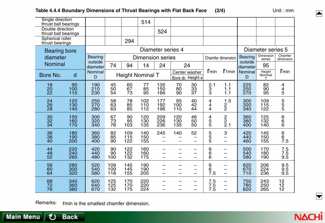
Single directionthrust ball bearingsDouble directionthrust ball bearingsSpherical rollerthrust bearings
Bore No. d
Bearing borediameterNominal
Chamferdimension
rmin95
Dimensionseries
HeightNominal
T
Diameter series 5Bearingoutside
diameterNominal
DHeight Nominal T
9474 2414Dimension series
24Center washer
Diameter series 4
514
524
294
Bearingoutside
diameterNominal
D
Chamfer dimension
rmin r1minBore d2 Height a
190210230
250270280
300320340
360380400
420440480
520540580
620640670
455054
586363
677378
828590
9090
100
109109118
125125132
606773
788585
9095
103
109115122
122122132
145145155
170170175
778595
102110112
120130135
140150155
160160175
190190205
220220224
135150166
177192196
209226236
245––
–––
–––
–––
708090
95100110
120130135
140––
–––
–––
–––
303337
404244
465050
52––
–––
–––
–––
2.1 3 3
4 4 4
4 5 5
5 5 5
6 6 6
6 6 7.5
7.5 7.5 7.5
1.11.11.1
1.522
222.1
3––
–––
–––
–––
225250270
300320340
360380400
420440460
500540580
620670710
750780820
829095
109115122
125132140
145150155
170180190
206224236
243250265
445
555
666
667.5
7.57.59.5
9.59.59.5
121212
182022
242628
303234
363840
444852
566064
687276
90100110
120130140
150160170
180190200
220240260
280300320
340360380
Table 4.4.4 Boundary Dimensions of Thrust Bearings with Flat Back Face
rmin is the smallest chamfer dimension.Remarks:
Unit : mm(2/4)

Single directionthrust ball bearingsDouble directionthrust ball bearingsSpherical rollerthrust bearings
Bore No. d
Bearing borediameterNominal
Chamferdimension
rmin95
Dimensionseries
HeightNominal
T
Diameter series 5Bearingoutside
diameterNominal
DHeight Nominal T
9474 2414Dimension series
24Center washer
Diameter series 4
514
524
294
Bearingoutside
diameterNominal
D
Chamfer dimension
rmin r1minBore d2 Height a
710730780
800850870
920980
1030
109011501220
128013601440
152016001670
177018601950
140140155
155165165
175190195
206218230
236250
–
–––
–––
185185206
206224224
236250258
280290308
315335354
372390402
426444462
243243265
265290290
308335335
365375400
412438
–
–––
–––
–––
–––
–––
–––
–––
–––
–––
–––
–––
–––
–––
–––
–––
–––
–––
–––
–––
–––
–––
–––
–––
7.5 7.5 9.5
9.5 9.5 9.5
9.51212
121515
151515
151515
151519
–––
–––
–––
–––
–––
–––
–––
850900950
98010001060
109011501220
128013201400
–––
–––
–––
272290308
315315335
335355375
388388412
–––
–––
–––
121515
151515
151515
151515
–––
–––
–––
808488
9296
/500
/530/560/600
/630/670/710
/750/800/850
/900/950
/1000
/1060/1120/1180
400420440
460480500
530560600
630670710
750800850
900950
1000
106011201180
Table 4.4.4 Boundary Dimensions of Thrust Bearings with Flat Back Face
rmin is the smallest chamfer dimension.Remarks:
Unit : mm(3/4)

Single directionthrust ball bearingsDouble directionthrust ball bearingsSpherical rollerthrust bearings
Bore No. d
Bearing borediameterNominal
Chamferdimension
rmin95
Dimensionseries
HeightNominal
T
Diameter series 5Bearingoutside
diameterNominal
DHeight Nominal T
9474 2414Dimension series
24Center washer
Diameter series 4
514
524
294
Bearingoutside
diameterNominal
D
Chamfer dimension
rmin r1minBore d2 Height a
205021602280
–––
–––
–––
–
–––
–––
–––
–––
–
480505530
–––
–––
–––
–
–––
–––
–––
–––
–
–––
–––
–––
–––
–
–––
–––
–––
–––
–
–––
–––
–––
–––
–
191919
– – –
– – –
– – –
–
–––
–––
–––
–––
–
–––
–––
–––
–––
–
–––
–––
–––
–––
–
–––
–––
–––
–––
–
/1250/1320/1400
/1500/1600/1700
/1800/1900/2000
/2120/2240/2360
/2500
125013201400
150016001700
180019002000
212022402360
2500
Table 4.4.4 Boundary Dimensions of Thrust Bearings with Flat Back Face
rmin is the smallest chamfer dimension.Remarks:
Unit : mm(4/4)

Bearingoutside
diameterNominal
D
Fillet radiusat snap ring
groovebottom
r0
Max Min Max Min Max Min Max Min Max
Snap ringgroove diameter
D1
Snap ringgroove width
bDimension series 18 Dimension series 19Applicablesnap ring
Snap ring groove location a
Unit: mm
222428
303234
373940
424445
475255
20.822.826.7
28.730.732.7
35.737.738.7
40.742.743.7
45.750.753.7
20.522.526.4
28.430.432.4
35.437.438.4
40.442.443.4
45.450.453.4
–––
–1.31.3
1.3–
1.3
1.31.3–
1.31.3–
– – –
–1.151.15
1.15 –1.15
1.151.15 –
1.151.15 –
1.051.051.3
1.3 – –
1.71.7 –
1.7 –1.7
1.71.71.7
0.90.91.15
1.15 – –
1.551.55 –
1.55 –1.55
1.551.551.55
1.051.051.2
1.21.21.2
1.21.21.2
1.21.21.2
1.21.21.2
0.80.80.95
0.950.950.95
0.950.950.95
0.950.950.95
0.950.950.95
0.20.20.25
0.250.250.25
0.250.250.25
0.250.250.25
0.250.250.25
NR1022NR1024NR1028
NR1030NR1032NR1034
NR1037NR1039NR1040
NR1042NR1044NR1045
NR1047NR1052NR1055
Chamfer at groove side of outer ring clears a fillet radius of:0.3 mm in dimension series 18 up to and including D = 78 mm and
in dimension series 19 up to and including D = 47 mm;0.5 mm in dimension series 18 over D = 78 mm and
in dimension series 19 over D = 47 mm
Remarks:ab
r0 r0
D
1φ
Table 4.5.1 Dimensions of Snap Ring Grooves for Bearing Dimension Series 18 and 19 (1/3)

Bearingoutside
diameterNominal
D
Fillet radiusat snap ring
groovebottom
r0
Max Min Max Min Max Min Max Min Max
Snap ringgroove diameter
D1
Snap ringgroove width
bDimension series 18 Dimension series 19Applicablesnap ring
Snap ring groove location a
Unit: mm
586265
687278
808590
95100105
56.760.763.7
66.770.776.2
77.982.987.9
92.997.9
102.6
56.460.363.3
66.370.375.8
77.582.587.5
92.597.5
102.1
1.3–
1.3
–1.71.7
–1.71.7
1.71.7–
1.15 –1.15
–1.551.55
–1.551.55
1.551.55 –
–1.7 –
1.71.7 –
2.12.12.1
–2.52.5
–1.55 –
1.551.55 –
1.91.91.9
–2.32.3
1.21.21.2
1.21.21.6
1.61.61.6
1.61.61.6
0.950.950.95
0.950.951.3
1.31.31.3
1.31.31.3
0.250.250.25
0.250.250.4
0.40.40.4
0.40.40.4
NR1058NR1062NR1065
NR1068NR1072NR1078
NR1080NR1085NR1090
NR1095NR1100NR1105
Chamfer at groove side of outer ring clears a fillet radius of:0.3 mm in dimension series 18 up to and including D = 78 mm and
in dimension series 19 up to and including D = 47 mm;0.5 mm in dimension series 18 over D = 78 mm and
in dimension series 19 over D = 47 mm
Remarks:ab
r0 r0
D
1φ
Table 4.5.1 Dimensions of Snap Ring Grooves for Bearing Dimension Series 18 and 19 (2/3)

Bearingoutside
diameterNominal
D
Fillet radiusat snap ring
groovebottom
r0
Max Min Max Min Max Min Max Min Max
Snap ringgroove diameter
D1
Snap ringgroove width
bDimension series 18 Dimension series 19Applicablesnap ring
Snap ring groove location a
Unit: mm
110115120
125130140
145150165
175180190200
107.6112.6117.6
122.6127.6137.6
142.6147.6161.8
171.8176.8186.8196.8
107.1112.1117.1
122.1127.1137.1
142.1147.1161.3
171.3176.3186.3196.3
2.12.12.1
2.12.12.5
–2.53.3
3.3–
3.33.3
1.91.91.9
1.91.92.3
–2.33.1
3.1 –3.13.1
2.5 –3.3
3.33.33.3
3.33.33.7
–3.73.7 –
2.3 –3.1
3.13.13.1
3.13.13.5
–3.53.5 –
1.61.61.6
1.61.62.2
2.22.22.2
2.22.22.22.2
1.31.31.3
1.31.31.9
1.91.91.9
1.91.91.91.9
0.40.40.4
0.40.40.6
0.60.60.6
0.60.60.60.6
NR1110NR1115NR1120
NR1125NR1130NR1140
NR1145NR1150NR1165
NR1175NR1180NR1190NR1200
Chamfer at groove side of outer ring clears a fillet radius of:0.3 mm in dimension series 18 up to and including D = 78 mm and
in dimension series 19 up to and including D = 47 mm;0.5 mm in dimension series 18 over D = 78 mm and
in dimension series 19 over D = 47 mm
Remarks:ab
r0 r0
D
1φ
Table 4.5.1 Dimensions of Snap Ring Grooves for Bearing Dimension Series 18 and 19 (3/3)
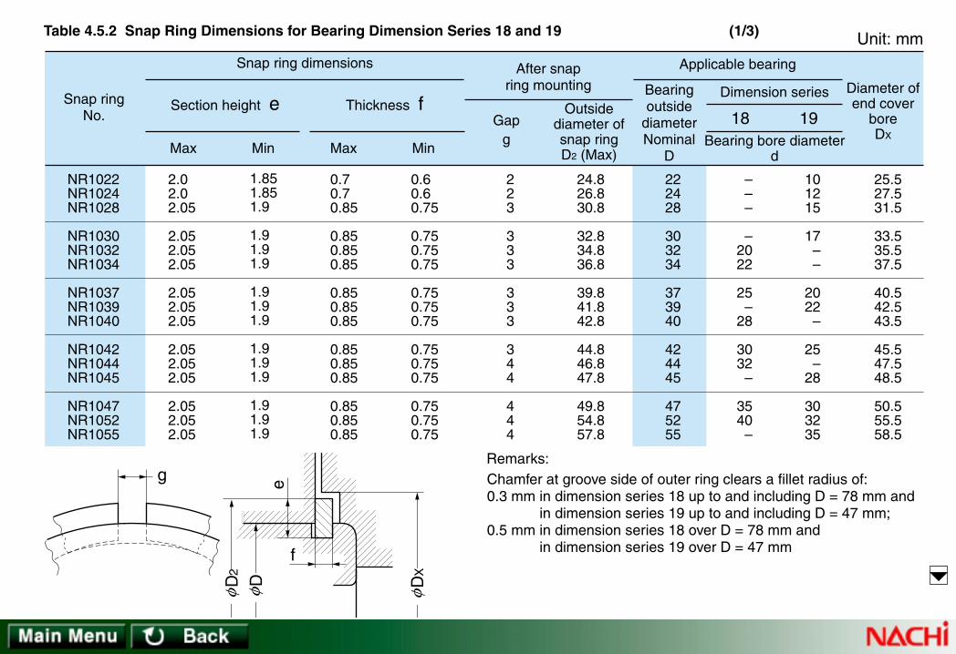
Max Min Max Min
Gapg Bearing bore diameter
d
Thickness f
After snapring mounting
Snap ring dimensions
Unit: mm
Snap ringNo.
Section height e Outsidediameter ofsnap ringD2 (Max)
Bearingoutside
diameterNominal
D
Applicable bearing
18 19
Dimension series Diameter ofend cover
boreDX
2.02.02.05
2.052.052.05
2.052.052.05
2.052.052.05
2.052.052.05
1.851.851.9
1.91.91.9
1.91.91.9
1.91.91.9
1.91.91.9
223
333
333
344
444
24.826.830.8
32.834.836.8
39.841.842.8
44.846.847.8
49.854.857.8
222428
303234
373940
424445
475255
NR1022NR1024NR1028
NR1030NR1032NR1034
NR1037NR1039NR1040
NR1042NR1044NR1045
NR1047NR1052NR1055
0.70.70.85
0.850.850.85
0.850.850.85
0.850.850.85
0.850.850.85
0.60.60.75
0.750.750.75
0.750.750.75
0.750.750.75
0.750.750.75
–––
–2022
25–
28
3032
–
3540
–
101215
17––
2022
–
25–
28
303235
25.5 27.5 31.5
33.5 35.5 37.5
40.5 42.5 43.5
45.5 47.5 48.5
50.5 55.5 58.5
Chamfer at groove side of outer ring clears a fillet radius of:0.3 mm in dimension series 18 up to and including D = 78 mm and
in dimension series 19 up to and including D = 47 mm;0.5 mm in dimension series 18 over D = 78 mm and
in dimension series 19 over D = 47 mm
Remarks:g
D
2
D
D
X
f
e
φ φ φ
Table 4.5.2 Snap Ring Dimensions for Bearing Dimension Series 18 and 19 (1/3)

Max Min Max Min
Gapg Bearing bore diameter
d
Thickness f
After snapring mounting
Snap ring dimensions
Unit: mm
Snap ringNo.
Section height e Outsidediameter ofsnap ringD2 (Max)
Bearingoutside
diameterNominal
D
Applicable bearing
18 19
Dimension series Diameter ofend cover
boreDX
2.052.052.05
2.052.053.25
3.253.253.25
3.253.254.04
1.91.91.9
1.91.93.1
3.13.13.1
3.13.13.89
444
555
555
555
60.864.867.8
70.874.882.7
84.489.494.4
99.4104.4110.7
586265
687278
808590
95100105
NR1058NR1062NR1065
NR1068NR1072NR1078
NR1080NR1085NR1090
NR1095NR1100NR1105
0.850.850.85
0.850.851.12
1.121.121.12
1.121.121.12
0.750.750.75
0.750.751.02
1.021.021.02
1.021.021.02
45–
50
–5560
–6570
7580
–
–40
–
4550
–
556065
–7075
61.5 65.5 68.5
727684
869196
101106112
Chamfer at groove side of outer ring clears a fillet radius of:0.3 mm in dimension series 18 up to and including D = 78 mm and
in dimension series 19 up to and including D = 47 mm;0.5 mm in dimension series 18 over D = 78 mm and
in dimension series 19 over D = 47 mm
Remarks:g
D
2
D
D
X
f
e
φ φ φ
Table 4.5.2 Snap Ring Dimensions for Bearing Dimension Series 18 and 19 (2/3)

Max Min Max Min
Gapg Bearing bore diameter
d
Thickness f
After snapring mounting
Snap ring dimensions
Unit: mm
Snap ringNo.
Section height e Outsidediameter ofsnap ringD2 (Max)
Bearingoutside
diameterNominal
D
Applicable bearing
18 19
Dimension series Diameter ofend cover
boreDX
4.044.044.04
4.044.044.04
4.044.044.85
4.854.854.854.85
3.893.893.89
3.893.893.89
3.893.894.7
4.74.74.74.7
557
777
777
10101010
115.7120.7125.7
130.7135.7145.7
150.7155.7171.5
181.5186.5196.5206.5
110115120
125130140
145150165
175180190200
NR1110NR1115NR1120
NR1125NR1130NR1140
NR1145NR1150NR1165
NR1175NR1180NR1190NR1200
1.121.121.12
1.121.121.7
1.71.71.7
1.71.71.71.7
1.021.021.02
1.021.021.6
1.61.61.6
1.61.61.61.6
859095
100105110
–120130
140–
150160
80–
85
9095
100
105110120
–130140
–
117122127
132137147
152157173
183188198208
Chamfer at groove side of outer ring clears a fillet radius of:0.3 mm in dimension series 18 up to and including D = 78 mm and
in dimension series 19 up to and including D = 47 mm;0.5 mm in dimension series 18 over D = 78 mm and
in dimension series 19 over D = 47 mm
Remarks:g
D
2
D
D
X
f
e
φ φ φ
Table 4.5.2 Snap Ring Dimensions for Bearing Dimension Series 18 and 19 (3/3)

Bearingoutside
diameterNominal
D
Fillet radiusat snap ring
groovebottom
r0
Max Min Max Min Max Min Max Min Max
Snap ringgroove diameter
D1
Snap ringgroove width
bDiameter series 0Diameter series
2, 3, 4Applicablesnap ring
Snap ring groove location a
Unit: mm
13
161922
242628
303235
374042
12.04
15.1618.2521.11
23 25.1526.7
28.1730.1533.17
34.7738.1 39.75
11.91
15.0418.1 20.95
22.8525 26.4
27.9129.9 32.92
34.5237.8539.5
–
–1.731.73
1.731.731.73
–2.062.06
––
2.06
–
–1.551.55
1.551.551.55
–1.91.9
– –1.9
1.1
1.21.731.73
1.731.731.73
2.062.062.06
2.062.062.06
0.95
1.051.551.55
1.551.551.55
1.91.91.9
1.91.91.9
1.05
1.051.051.05
1.051.051.2
1.651.651.65
1.651.651.65
0.8
0.8 0.8 0.8
0.8 0.8 0.95
1.351.351.35
1.351.351.35
0.2
0.2 0.2 0.2
0.2 0.2 0.25
0.40.40.4
0.40.40.4
NR 13
NR 16 NR 19 NR 22
NR 24 NR 26 NR 28
NR 30NR 32NR 35
NR 37NR 40NR 42
1. These dimensions are not applied to dimension series 00, 82 and 83.2. Chamfer at groove side of outer ring clears a fillet radius of:
0.3 mm in diameter series 0 up to and including D = 35 mm,0.5 mm in diameter series 0 over D = 35 mm and for all diameters
in diameter series 2, 3, and 4
Remarks:ab
r0 r0
D
1φ
Table 4.5.3 Dimensions of Snap Ring Grooves for Bearing Diameter Series 0, 2, 3 and 4 (1/4)

Bearingoutside
diameterNominal
D
Fillet radiusat snap ring
groovebottom
r0
Max Min Max Min Max Min Max Min Max
Snap ringgroove diameter
D1
Snap ringgroove width
bDiameter series 0Diameter series
2, 3, 4Applicablesnap ring
Snap ring groove location a
Unit: mm
444750
525556
586265
687275
41.7544.6 47.6
49.7352.6 53.6
55.6 59.6162.6
64.8268.8171.83
41.5 44.3547.35
49.4852.3553.35
55.3559.1162.1
64.3168.3 71.32
2.062.06
–
2.062.08
–
2.082.08
–
2.49–
2.49
1.91.9 –
1.91.88 –
1.881.88 –
2.29 –2.29
–2.462.46
2.46 –2.46
2.463.283.28
3.283.283.28
–2.312.31
2.31 –2.31
2.313.073.07
3.073.073.07
1.651.651.65
1.651.651.65
1.652.22.2
2.22.22.2
1.351.351.35
1.351.351.35
1.351.91.9
1.91.91.9
0.40.40.4
0.40.40.4
0.40.60.6
0.60.60.6
NR 44NR 47NR 50
NR 52NR 55NR 56
NR 58NR 62NR 65
NR 68NR 72NR 75
1. These dimensions are not applied to dimension series 00, 82 and 83.2. Chamfer at groove side of outer ring clears a fillet radius of:
0.3 mm in diameter series 0 up to and including D = 35 mm,0.5 mm in diameter series 0 over D = 35 mm and for all diameters
in diameter series 2, 3, and 4
Remarks:ab
r0 r0
D
1φ
Table 4.5.3 Dimensions of Snap Ring Grooves for Bearing Diameter Series 0, 2, 3 and 4 (2/4)

Bearingoutside
diameterNominal
D
Fillet radiusat snap ring
groovebottom
r0
Max Min Max Min Max Min Max Min Max
Snap ringgroove diameter
D1
Snap ringgroove width
bDiameter series 0Diameter series
2, 3, 4Applicablesnap ring
Snap ring groove location a
Unit: mm
808590
95100110
115120125
130140145
76.8181.8186.79
91.8296.8
106.81
111.81115.21120.22
125.22135.23140.23
76.3 81.3186.28
91.3196.29
106.3
111.3 114.71119.71
124.71134.72139.73
2.49–
2.87
2.872.872.87
2.87–
2.87
2.873.713.71
2.29 –2.67
2.672.672.67
2.67 –2.67
2.673.453.45
3.283.283.28
–3.283.28
–4.064.06
4.064.9 –
3.073.073.07
–3.073.07
–3.863.86
3.864.65 –
2.22.23
333
33.43.4
3.43.43.4
1.91.92.7
2.72.72.7
2.73.13.1
3.13.13.1
0.60.60.6
0.60.60.6
0.60.60.6
0.60.60.6
NR 80NR 85NR 90
NR 95NR100NR110
NR115NR120NR125
NR130NR140NR145
1. These dimensions are not applied to dimension series 00, 82 and 83.2. Chamfer at groove side of outer ring clears a fillet radius of:
0.3 mm in diameter series 0 up to and including D = 35 mm,0.5 mm in diameter series 0 over D = 35 mm and for all diameters
in diameter series 2, 3, and 4
Remarks:ab
r0 r0
D
1φ
Table 4.5.3 Dimensions of Snap Ring Grooves for Bearing Diameter Series 0, 2, 3 and 4 (3/4)

Bearingoutside
diameterNominal
D
Fillet radiusat snap ring
groovebottom
r0
Max Min Max Min Max Min Max Min Max
Snap ringgroove diameter
D1
Snap ringgroove width
bDiameter series 0Diameter series
2, 3, 4Applicablesnap ring
Snap ring groove location a
Unit: mm
150160170
180190200
210215225
230240250
145.24155.22163.65
173.66183.64193.65
203.6 208.6 217
222 232 242
144.73154.71163.14
173.15183.13193.14
203.1 208.1 216.5
221.5 231.5 241.5
3.713.713.71
3.71–
5.69
5.69–
6.5
–6.5
–
3.453.453.45
3.45 –5.44
5.44 –6.2
–6.2 –
4.94.95.69
5.695.695.69
–5.696.5
6.56.56.5
4.654.655.44
5.445.445.44
–5.446.2
6.26.26.2
3.43.43.8
3.83.83.8
3.8 3.8 4.9
4.9 4.9 4.9
3.13.13.5
3.53.53.5
3.5 3.5 4.5
4.5 4.5 4.5
0.60.60.6
0.60.60.6
1 1 1
1 1 1
NR150NR160NR170
NR180NR190NR200
NR210 NR215 NR225
NR230 NR240 NR250
1. These dimensions are not applied to dimension series 00, 82 and 83.2. Chamfer at groove side of outer ring clears a fillet radius of:
0.3 mm in diameter series 0 up to and including D = 35 mm,0.5 mm in diameter series 0 over D = 35 mm and for all diameters
in diameter series 2, 3, and 4
Remarks:ab
r0 r0
D
1φ
Table 4.5.3 Dimensions of Snap Ring Grooves for Bearing Diameter Series 0, 2, 3 and 4 (4/4)

4320
Max Min Max Min
Gapg Bearing bore diameter
d
Thickness f
After snapring mounting
Snap ring dimensions
Unit: mm
Snap ringNo. Section height e
Outsidediameter ofsnap ringD2 (Max)
Bearingoutside
diameterNominal
D
Applicable bearing
Dimension seriesDiameter ofend cover
boreDX
(Min)
1.15
1.65 1.65 2.00
2.00 2.00 2.05
3.253.253.25
3.253.253.25
1.0
1.5 1.5 1.85
1.85 1.85 1.90
3.13.13.1
3.13.13.1
3
3 3 3
3 3 3
333
333
14.3
18.5 21.5 25.1
27 29.2 30.8
34.736.739.7
41.344.646.3
13
16 19 22
24 26 28
303235
374042
NR 13
NR 16 NR 19 NR 22
NR 24 NR 26 NR 28
NR 30NR 32NR 35
NR 37NR 40NR 42
0.7
0.7 0.7 0.7
0.7 0.7 0.85
1.121.121.12
1.121.121.12
0.6
0.6 0.6 0.6
0.6 0.6 0.75
1.021.021.02
1.021.021.02
14.5
19 22 25.5
27.5 30 31.5
35.5 37.5 40.5
42 45.5 47
3
4 5 6
– 7 8
9– 10
12– 15
4
5 6 7
8 9 –
101215
– 17–
–
– 7 8
9 10 12
– 1517
– –
20
–
– – –
– – –
89
–
10– 12
1. These dimensions are not applied to dimension series 00, 82 and 83.2. Chamfer at groove side of outer ring clears a fillet radius of:
0.3 mm in diameter series 0 up to and including D = 35 mm,0.5 mm in diameter series 0 over D = 35 mm and for all diameters
in diameter series 2, 3, and 4
Remarks:g
f
e
D
2
D
D
X
φ φ φ
Table 4.5.4 Snap Ring Dimensions for Bearing Diameter Series 0, 2, 3 and 4 (1/4)

4320
Max Min Max Min
Gapg Bearing bore diameter
d
Thickness f
After snapring mounting
Snap ring dimensions
Unit: mm
Snap ringNo. Section height e
Outsidediameter ofsnap ringD2 (Max)
Bearingoutside
diameterNominal
D
Applicable bearing
Dimension seriesDiameter ofend cover
boreDX
(Min)
3.254.044.04
4.044.044.04
4.044.044.04
4.854.854.85
3.13.893.89
3.893.893.89
3.893.893.89
4.74.74.7
344
444
444
555
48.352.755.7
57.960.761.7
63.767.770.7
74.678.681.6
444750
525556
586265
687275
NR 44NR 47NR 50
NR 52NR 55NR 56
NR 58NR 62NR 65
NR 68NR 72NR 75
1.121.121.12
1.121.121.12
1.121.71.7
1.71.71.7
1.021.021.02
1.021.021.02
1.021.61.6
1.61.61.6
49 53.5 56.5
58.5 61.5 62.5
64.5 68.5 71.5
76 80 83
– 17–
20– 22
– 25–
283032
– 2022
25– –
283032
– 35–
2225–
2830–
3235–
40– 45
– – –
15– –
– 17–
– 20–
1. These dimensions are not applied to dimension series 00, 82 and 83.2. Chamfer at groove side of outer ring clears a fillet radius of:
0.3 mm in diameter series 0 up to and including D = 35 mm,0.5 mm in diameter series 0 over D = 35 mm and for all diameters
in diameter series 2, 3, and 4
Remarks:g
f
e
D
2
D
D
X
φ φ φ
Table 4.5.4 Snap Ring Dimensions for Bearing Diameter Series 0, 2, 3 and 4 (2/4)

4320
Max Min Max Min
Gapg Bearing bore diameter
d
Thickness f
After snapring mounting
Snap ring dimensions
Unit: mm
Snap ringNo. Section height e
Outsidediameter ofsnap ringD2 (Max)
Bearingoutside
diameterNominal
D
Applicable bearing
Dimension seriesDiameter ofend cover
boreDX
(Min)
4.854.854.85
4.854.854.85
4.857.217.21
7.217.217.21
4.74.74.7
4.74.74.7
4.77.067.06
7.067.067.06
555
555
577
777
86.691.696.5
101.6106.5116.6
121.6129.7134.7
139.7149.7154.7
808590
95100110
115120125
130140145
NR 80NR 85NR 90
NR 95NR100NR110
NR115NR120NR125
NR130NR140NR145
1.71.72.46
2.462.462.46
2.462.822.82
2.822.822.82
1.61.62.36
2.362.362.36
2.362.722.72
2.722.722.72
88 93 98
103 108 118
123 131.5 136.5
141.5 152 157
35–
40
– 4550
– 55–
6065–
404550
– 5560
– 6570
7580–
50– 55
606570
75– 80
859095
25–
30
– 3540
– 45–
5055–
1. These dimensions are not applied to dimension series 00, 82 and 83.2. Chamfer at groove side of outer ring clears a fillet radius of:
0.3 mm in diameter series 0 up to and including D = 35 mm,0.5 mm in diameter series 0 over D = 35 mm and for all diameters
in diameter series 2, 3, and 4
Remarks:g
f
e
D
2
D
D
X
φ φ φ
Table 4.5.4 Snap Ring Dimensions for Bearing Diameter Series 0, 2, 3 and 4 (3/4)

4320
Max Min Max Min
Gapg Bearing bore diameter
d
Thickness f
After snapring mounting
Snap ring dimensions
Unit: mm
Snap ringNo. Section height e
Outsidediameter ofsnap ringD2 (Max)
Bearingoutside
diameterNominal
D
Applicable bearing
Dimension seriesDiameter ofend cover
boreDX
(Min)
7.217.219.6
9.6 9.6 9.6
9.6 9.6
10
10 10 10
7.067.069.45
9.459.459.45
9.45 9.45 9.85
9.85 9.85 9.85
77
10
101010
10 10 10
10 10 10
159.7169.7182.9
192.9202.9212.9
222.8 227.8 237
242 252 262
150160170
180190200
210 215 225
230 240 250
NR150NR160NR170
NR180NR190NR200
NR210 NR215 NR225
NR230 NR240 NR250
2.822.823.1
3.13.13.1
3.1 3.1 3.5
3.5 3.5 3.5
2.722.723
333
3 3 3.4
3.4 3.4 3.4
162 172 185
195 205 215
225 230 240
245 255 265
707580
859095
– 100 105
– 110
–
859095
100105110
– 120
–
130 –
140
100105110
120–
130
140 –
150
– 160
–
6065–
707580
85 – 90
– 95
100
1. These dimensions are not applied to dimension series 00, 82 and 83.2. Chamfer at groove side of outer ring clears a fillet radius of:
0.3 mm in diameter series 0 up to and including D = 35 mm,0.5 mm in diameter series 0 over D = 35 mm and for all diameters
in diameter series 2, 3, and 4
Remarks:g
f
e
D
2
D
D
X
φ φ φ
Table 4.5.4 Snap Ring Dimensions for Bearing Diameter Series 0, 2, 3 and 4 (4/4)

MaterialSymbol
SupplementarySymbol
Table.4.6.1
CageSymbol
SpecialDesignSymbol
Seal orshield
Ringmodification
*Duplexmounting
Internalclearance
*Sleeve Tolerance *Grease
Supplementary symbol
Table.4.6.4 Table.4.6.5 Table.4.6.6 Table.4.6.7 Table.4.6.8 Table.4.6.9 Table.4.6.10 Table.4.6.11 Table.4.6.12
TypeSymbol
DimensionSeries
Number
BoreDiameterNumber
ContactAngle
Symbol
Basic Number
Table.4.6.2 Table.4.6.3
Note 1:
Remarks:1. Symbol in parentheses can be omitted.2. Code marked with "*" is not marked on bearing.3. Bearing modification symbol NR is marked
without R on bearing.
Denotes polyamide cages for angular contact ball bearing of contact angle symbol C.
4.6 Nachi Bearing Numbers4.6 Nachi Bearing Numbers
Fig 4.8 NACHI Bearing Prefixes and Suffixes

Suffix DescriptionDBDF
+ α
UDU
Back-to-back mountingFace-to-face mounting
Flush ground angular contactball bearing
DT Tandem mounting
KB DB mounting with spacer toouter ring
Spacer(α is nominal width in mm)
Table 4.6.8 *Duplex mounting
Prefix DescriptionCase hardened steelCase hardened steelCase hardened steelHigh speed steelStainless steel
B–C–D–H–S–
Table 4.6.1 Material Symbol
NNUNFNJNP
NUPNH
NNUNN
R
Cylindrical roller bearings
Cylindrical roller bearing rollerassembly and outer or inner ring
Prefix Description
Table 4.6.2 Type Symbol
Suffix Description
K
K30
N
NR
Tapered bore: 1/12 taper onbearing bore
Tapered bore: 1/30 taper onbearing bore
Snap ring groove on outerring without snap ringSnap ring on outer ring
Table 4.6.7 Ring modification

C(A)
BDC
Nominal contact angle over 10° under 22° (standard 15°)Nominal contact angle over 22° under 32° (standard 30°)Nominal contact angle over 32° under 45° (standard 40°)Nominal contact angle over 24° under 32°Nominal contact angle over 17° under 24°
Single row Angularcontact ball bearings
Tapered roller bearings
Suffix Description
Table 4.6.3 Contact Angle Symbol
Suffix Description
A
E
J
S26S28W20
Inner ring, bearing width variationfor Tapered roller bearingRoller bearing design changeTapered roller bearing ringsinterchangeableHeat stabilizedHeat stabilizedOil holes in outer ring
W33 Oil holes and groove in outer ring
E2Spherical roller bearing withmachined cage
EX High capacity spherical roller bearingA2X High speed spherical roller bearing
AEXHigh speed and high capacity sphericalroller bearing
V Special design for vibrating machine
Table 4.6.4 Special Design Symbol
Suffix DescriptionFGL
MYVY
Machined mild steel cageNon-metalic cageMachined light alloy cageMachined bronze cageNo cagePressed non-ferrous metal cage (Note 1)
Table 4.6.5 Cage Symbol
Suffix DescriptionZE
ZZENKE
– 2NKENSE
– 2NSE
Shield one sideShield both sidesLabyrinth seal one sideLabyrinth seal both sidesContact seal one sideContact seal both sides
ZZZNK
– 2NKNSL
– 2NSL
Table 4.6.6 Seal or shield

Suffix Description+H+AH
Adapter sleeveWithdrawal sleeve
Table 4.6.9 *Sleeve
Suffix DescriptionC1 Radial clearance C1C2 Radial clearance C2
(CN) Normal Radial clearanceC3 Radial clearance C3C4 Radial clearance C4C5 Radial clearance C5
C1P Radial clearance C1P (Note 2)(Note 2)
(Note 2)(Note 3)(Note 3)(Note 3)
C2P Radial clearance C2P
C6P Radial clearance C6PC9na Cylindrical roller bearing (C9)C1na Cylindrical roller bearing (C1)C2na Cylindrical roller bearing (C2)
(Note 3)Cna Cylindrical roller bearing (Normal)(Note 3)C3na Cylindrical roller bearing (C3)(Note 3)C4na Cylindrical roller bearing (C4)(Note 3)C5na Cylindrical roller bearing (C5)
CMElectric motor bearing radial clearance(of deep groove ball bearing and ofnon-interchangeable cylindrical roller bearing)
CT
··· ···
Radial clearance for electric motor bearing(interchangeable cylindrical roller bearings)
Note 2: Extra small ball bearing and miniature ball bearingNote 3: Non-interchangeable clearance
Table 4.6.10 Internal clearance
Suffix Description(0) JIS class 0 (ISO Normal class)P6 JIS class 6 (ISO class 6)
P6X JIS class 6XP5 JIS class 5 (ISO class 5)P4 JIS class 4 (ISO class 4)P2 JIS class 2 (ISO class 2)UP NACHI class UP
Table 4.6.11 Tolerance
Suffix DescriptionADC Shell Andoc CAV2 Shell Alvania grease 2S
BC325 Esso Beacon 325MTSRL Multemp SRL
Table 4.6.12 *Grease

The NACHI part number for rolling contact bearings consists of the basic number and supplementary codes. The part number definesthe bearing configuration, tolerance, general boundary dimensions, and other specifications.NACHI uses supplemental prefix and suffix symbols as shown in Fig. 4.8. The NACHI basic number consists of the following:
4
4
5
5
6
6
7
7
8
8
9
9
10
00
12
01
15
02
17
03
20
04
25
05
....
....
480
96
500
/500
530
/530
....
....
Bore (mm)
Bore diameternumber
Remarks Bore Diameter (bore dia.)/5 /bore diameter––––
Bore Diameter Number
NACHI Rolling Contact Bearing NumbersNACHI Rolling Contact Bearing Numbers ••• ••• ExamplesExamples
+ ++=
Dimension series no.
Boundary Dimensions
Bore Diameternumber
Widthseries no.*
Diameterseries no.
BasicNumber
Typesymbol
Bearing series symbol * Height series number for thrust bearings.
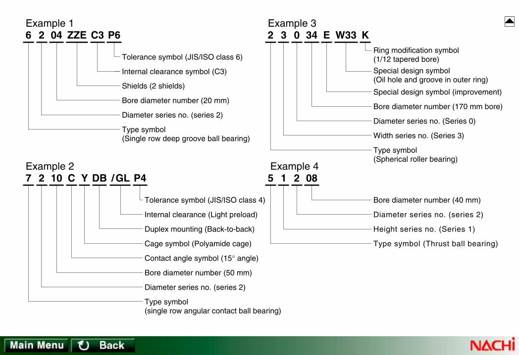
6 2 04 ZZE C3 P6
Tolerance symbol (JIS/ISO class 6)
Internal clearance symbol (C3)
Shields (2 shields)
Bore diameter number (20 mm)
Diameter series no. (series 2)
Type symbol (Single row deep groove ball bearing)
2 3 34 E W33 K
Width series no. (Series 3)
Type symbol(Spherical roller bearing)
0
Diameter series no. (Series 0)
Bore diameter number (170 mm bore)
Special design symbol (improvement)
Special design symbol(Oil hole and groove in outer ring)
Ring modification symbol(1/12 tapered bore)
7 2 10 C DB /GL
Type symbol(single row angular contact ball bearing)
Y P4
Diameter series no. (series 2)
Bore diameter number (50 mm)
Contact angle symbol (15° angle)
Cage symbol (Polyamide cage)
Duplex mounting (Back-to-back)
Internal clearance (Light preload)
Tolerance symbol (JIS/ISO class 4)
5 1 08
Height series no. (Series 1)
Type symbol (Thrust ball bearing)
2
Diameter series no. (series 2)
Bore diameter number (40 mm)
Example 1 Example 3
Example 2 Example 4

5.2 T5.2 Tolerance Volerance Values for Metric Talues for Metric Taperapered Roller Bearingsed Roller Bearings
• Table 5.1.1 Tolerance Values of Inner Ring and of Outer Ring Width• Table 5.1.2 Tolerance Values of Outer Ring
• Table 5.2.1 Tolerance Values of Inner Ring• Table 5.2.2 Tolerance Values of Outer Ring• Table 5.2.3 Deviations of Single Ring Width, Bearing Width and Duplex/Stack Mounted Bearing Width
IntrIntroductionoduction
5.1 T5.1 Tolerance Volerance Values for Radial Bearingsalues for Radial Bearings (Except T(Except Taperapered Roller Bearings)ed Roller Bearings)
5.3 T5.3 Tolerance Volerance Values for Thralues for Thrust Ball Bearingsust Ball Bearings• Table 5.3.1 Tolerance Values of Shaft Washer Bore Diameter• Table 5.3.2 Tolerance Values of Housing Washer Outside Diameter• Table 5.3.3 Height Tolerances of Thrust Ball Bearings (with Flat Seat) and Center Washers (Class 0)
5.4 T5.4 Tolerance Volerance Values of Spherical Roller Thralues of Spherical Roller Thrust Bearings (Class 0)ust Bearings (Class 0)
5.5 T5.5 Tolerance Volerance Values of Talues of Taperapered Roller Bearings - Inch Seriesed Roller Bearings - Inch Series• Table 5.5.1 Tolerance of Inner Ring (Cone) Bore• Table 5.5.2 Tolerance of Outer Ring (Cup) Outside Diameter• Table 5.5.3 Tolerance of Bearing Width and Duplex/Stack Mounted Bearing Width• Table 5.5.4 Radial Runout of Assembled Bearing Inner Ring and Outer Ring
• Table 5.4.1 Tolerance Values of Inner Rings • Table 5.4.2 Tolerance Values of Outer Rings
5.6 Chamfer Dimensions5.6 Chamfer Dimensions
5.7 T5.7 Taperapered Bored Boreses
5. Accuracy of Bearings5. Accuracy of Bearings

5. Accuracy of Rolling Contact Bearings5. Accuracy of Rolling Contact Bearings
The tolerance of rolling contact bearings includes dimensional and running accuracy. According to JIS (1), tolerance is classified into 6classes; class 0, 6, 6X, 5, 4 and 2 with accuracy ascending from class 0 to 2.Applicable tolerance classes to individual bearing types and applicable standards are shown in the next page.
Accuracy of Rolling Contact Bearings
Dimensional Accuracy
Mounting element tolerances• Bearing bore, outside dia., width• Width variation• Inscribed and circumscribed circle diameter of rollers• Chamfer dimensions• Tapered bore
Dynamic elements• Radial run-out of rings• Axial run-out of rings• Side face run-out of rings• Tolerance of variation outer ring raceway dia. to outside dia.
Running Accuracy

JIS 0
JIS 0
JIS 0
JIS 0
JIS 0
CLASS 4
JIS 0
JIS 0
JIS 6
JIS 6
JIS 6
–
JIS 0 JIS 6X
CLASS 2
JIS 6
–
JIS 5
JIS 5
–
JIS 5
–
JIS 5JIS 6
CLASS 3
JIS 5
–
JIS 4
JIS 4
–
JIS 4
–
JIS 4
CLASS 0
JIS 4
–
JIS 2
JIS 2
–
JIS 2
–
–
CLASS 00
–
–
JIS B 1514
JIS B 1514
JIS B 1514
ANSI / ABMA 19
JIS B 1514
JIS B 1514
5.1.1 5.1.2
5.1.1 5.1.2
5.2.1 5.2.25.2.3
5.5.1 5.5.25.5.3 5.5.4
5.3.1 5.3.25.3.3
5.4.1 5.4.2
NORMAL CLASS
ISO 492ISO 582 –
P0 P6 P5 P4 P2 DIN 620 –
–
–
ABEC 1 ABEC 3 ABEC 5 ABEC 7 ABEC 9 ANSI / ABMA 20
RBEC 1 RBEC 3 RBEC 5 – – ANSI / ABMA 20
CLASS 6 CLASS 5 CLASS 4 CLASS 2
Spherical Roller Thrust Bearings
Thrust, Ball Bearings
Spherical Roller (Radial) Bearings
Cylindrical Roller Bearings
Self-aligning Ball Bearings
Angular Contact Ball Bearings
Deep groove Ball Bearings
ComparativeClasses
Tapered Roller Bearings
Metric Series
Inch Series
ISO ( 2 )
D IN (3 )
ANSI (4) /
ABMA (5 )
Ball Bearings
Roller Bearings
Metric Radial Bearings (Except Tapered Roller Bearings) Class Comparison
Bearing Type Tolerance class Related Standard ReferenceTables
(1) Japanese Industrial Standard (2) International Organization for Standardization (3) German Industrial Standards(4) American National Standards Institute(5) American Bearing Manufacturers AssociationRemarks: For tolerances of chamfer dimensions, see Table 5.6; for accuracy of tapered bore, see Table 5.7.
–
Bearing types and tolerance classes

0.6 2.510
183050
80120150
180250315
400500630
800100012501600
2.51018
305080
120150180
250315400
500630800
1000125016002000
Over Incl.
Bearing borediameter Nominal
d(mm)
( 1 ) 000
000
000
000
000
0000
– 8– 8– 8
– 10– 12– 15
– 20– 25– 25
– 30– 35– 40
– 45– 50– 75
– 100– 125– 160– 200
000
000
000
000
00–
––––
– 7– 7– 7
– 8– 10– 12
– 15– 18– 18
– 22– 25– 30
– 35– 40
–
––––
000
000
000
000
–––
––––
– 5– 5– 5
– 6– 8– 9
– 10– 13– 13
– 15– 18– 23
–––
––––
000
000
000
0––
–––
––––
– 4– 4– 4
– 5– 6– 7
– 8– 10– 10
– 12––
–––
––––
000
000
000
0––
–––
––––
– 2.5– 2.5– 2.5
– 2.5– 2.5– 4
– 5 – 7 – 7
– 8 ––
–––
––––
000
000
000
0––
–––
––––
– 4– 4– 4
– 5– 6– 7
– 8– 10– 10
– 12––
–––
––––
000
000
000
0––
–––
––––
– 2.5– 2.5– 2.5
– 2.5– 2.5– 4
– 5 – 7 – 7
– 8 ––
–––
––––
High Low High Low High Low High Low High Low High Low High Low0,1,2,3,4
Diameter seriesClass 4
Class 0 Class 6 Class 5 Class 4 Class 2 Class 2
Single plane mean bore diameter deviation Deviation of a single bore diameter (2)Bearing with cylindrical bore
mpd sd
Notes:
Remarks: The high deviation of bearing cylindrical bore diameter specified in this table does not apply within a distance of 1.2 × r (max) from the ring face.
(1) This diameter is included in this group.(2) Applies to bearings with cylindrical bore.(3) Width deviation and variation of outer ring are the same with of inner ring. Outer ring width variation of classes 5, 4 and 2 are listed in Table 5.1.2.(4) Applies to the rings of single bearings made for paired of stack mounting.(5) Applies ro radial ball bearings such as deep groove ball bearing, angular contact ball bearings.
Unit: mµTable 5.1.1 Tolerance Values of Inner Ring and of Outer Ring Width (1/4)

0.6 2.510
183050
80120150
180250315
400500630
800100012501600
2.51018
305080
120150180
250315400
500630800
1000125016002000
Over Incl.
Bearing borediameter Nominal
d(mm)
( 1 ) 101010
131519
253131
384450
5663–
––––
8 8 8
101219
253131
384450
5663–
––––
6 6 6
8 911
151919
232630
3438–
––––
9 9 9
101315
192323
283138
4450–
––––
7 7 7
81015
192323
283138
4450–
––––
5 5 5
6 8 9
111414
171923
2630–
––––
5 5 5
6 8 9
101313
151823
–––
––––
4 4 4
5 6 7
81010
121418
–––
––––
4 4 4
5 6 7
81010
12––
–––
––––
333
455
688
9––
–––
––––
2.52.52.5
2.52.54
5 7 7
8 ––
–––
––––
6 6 6
8 911
151919
232630
3438–
––––
5 5 5
6 8 9
111414
171923
2630–
––––
3 3 3
3 4 5
5 7 7
8 912
–––
––––
2 2 2
2.53 3.5
4 5 5
6 ––
–––
––––
1.51.51.5
1.51.52
2.53.53.5
4 ––
–––
––––
7,8,9 0,1 2,3,4 7,8,9 0,1 2,3,4 7,8,9 0,1,2,3,4 7,8,9 0,1,2,3,4Class 2 Class 0 Class 6 Class 5 Class 4 Class 2Diameter series
Class 0Diameter series
Class 6Diameter series
Class 5Diameter series
Class 4
Bore diameter variation in a single radial plane (2)Vd p
Main bore diameter variation (2)Vd mp
Bearing with cylindrical bore
Max Max Max Max Max Max Max Max Max Max
Unit: mµ
Notes:
Remarks: The high deviation of bearing cylindrical bore diameter specified in this table does not apply within a distance of 1.2 × r (max) from the ring face.
(1) This diameter is included in this group.(2) Applies to bearings with cylindrical bore.(3) Width deviation and variation of outer ring are the same with of inner ring. Outer ring width variation of classes 5, 4 and 2 are listed in Table 5.1.2.(4) Applies to the rings of single bearings made for paired of stack mounting.(5) Applies ro radial ball bearings such as deep groove ball bearing, angular contact ball bearings.
Table 5.1.1 Tolerance Values of Inner Ring and of Outer Ring Width (2/4)

0.6 2.510
183050
80120150
180250315
400500630
800100012501600
2.51018
305080
120150180
250315400
500630800
1000125016002000
( 1 )
Over Incl.
Bearing borediameter Nominal
d(mm)
000
000
000
000
000
0000
– 40– 120– 120
– 120– 120– 150
– 200– 250– 250
– 300– 350– 400
– 450– 500– 750
– 1000– 1250– 1600– 2000
000
000
000
000
–––
––––
– 40– 40– 80
– 120– 120– 150
– 200– 250– 250
– 300– 350– 400
–––
––––
000
000
000
0––
–––
––––
– 40– 40– 80
– 120– 120– 150
– 200– 250– 250
– 300––
–––
––––
–00
000
000
000
–––
––––
–– 250– 250
– 250– 250– 380
– 380– 500– 500
– 500– 500– 630
–––
––––
121520
202025
253030
303540
506070
80100 120 140
121520
202025
253030
303540
4550–
––––
555
556
788
101315
–––
––––
2.52.52.5
2.534
455
6––
–––
––––
High Low High Low High Low High Low High Low
Class 0Class 6
Class 5Class 4 Class 2
Class 0Class 6
Deviation of a single inner ring width (or a single outer ring width) (2) Inner (or outer) ring width variation
1.51.51.5
1.51.51.5
2.52.54
5––
–––
––––
000
000
000
000
–––
––––
– 250– 250– 250
– 250– 250– 250
– 380– 380– 380
– 500– 500– 630
–––
––––
MaxMaxMaxMaxMaxClass 0 Class 6 Class 5 Class 4 Class 2
Class 5Class 4
Single bearing Inner ring (or outer ring) (3) Inner ring
VBS (or VCS )Paired or stack mounted bearing (4)
sB sC
Unit: mµ
Notes:
Remarks: The high deviation of bearing cylindrical bore diameter specified in this table does not apply within a distance of 1.2 × r (max) from the ring face.
(1) This diameter is included in this group.(2) Applies to bearings with cylindrical bore.(3) Width deviation and variation of outer ring are the same with of inner ring. Outer ring width variation of classes 5, 4 and 2 are listed in Table 5.1.2.(4) Applies to the rings of single bearings made for paired of stack mounting.(5) Applies ro radial ball bearings such as deep groove ball bearing, angular contact ball bearings.
(or )
Table 5.1.1 Tolerance Values of Inner Ring and of Outer Ring Width (3/4)

0.6 2.510
183050
80120150
180250315
400500630
800100012501600
2.51018
305080
120150180
250315400
500630800
1000125016002000
( 1 )
Over Incl.
Bearing borediameter Nominal
d(mm)
333
445
577
8––
–––
––––
Class 4 Class 2
Max Max
Class 5
Max
333
445
566
7––
–––
––––
Class 4 Class 2
Max Max
777
888
91010
111315
–––
––––
Class 5
Max
Class 2
2.52.52.5
344
566
8 – –
– – –
– – – –
Class 4
444
455
688
101315
–––
––––
Class 5
Max
5 6 7
81010
131818
202530
3540–
––––
Class 6
Max
101010
131520
253030
405060
657080
90100120140
Class 0
Max
Radial runout of assembled bearing inner ring
MaxMax
1.51.51.5
2.52.52.5
2.52.55
5 – –
– – –
– – – –
1.51.51.5
1.51.51.5
2.52.54
5 – –
– – –
– – – –
777
888
91010
131520
–––
––––
1.51.51.5
2.52.52.5
2.52.55
5 – –
– – –
– – – –
Kia
Inner ring reference facerunout with bore
Assembled bearing inner ringface runout with raceway Sia (5)Sd
Unit: mµ
Notes:
Remarks: The high deviation of bearing cylindrical bore diameter specified in this table does not apply within a distance of 1.2 × r (max) from the ring face.
(1) This diameter is included in this group.(2) Applies to bearings with cylindrical bore.(3) Width deviation and variation of outer ring are the same with of inner ring. Outer ring width variation of classes 5, 4 and 2 are listed in Table 5.1.2.(4) Applies to the rings of single bearings made for paired of stack mounting.(5) Applies ro radial ball bearings such as deep groove ball bearing, angular contact ball bearings.
Table 5.1.1 Tolerance Values of Inner Ring and of Outer Ring Width (4/4)

2.56
18
305080
120150180
250315400
500630800
1000125016002000
61830
5080
120
150180250
315400500
630800
1000
1250160020002500
( 1 )
Over Incl.
Bearing outsidediameter Nominal
D(mm)
000
000
000
000
000
0000
– 8– 8– 9
– 11– 13– 15
– 18– 25– 30
– 35– 40– 45
– 50– 75– 100
– 125– 160– 200– 250
000
000
000
000
000
––––
– 7– 7– 8
– 9– 11– 13
– 15– 18– 20
– 25– 28– 33
– 38– 45– 60
––––
000
000
000
000
00–
––––
– 5– 5– 6
– 7– 9– 10
– 11– 13– 15
– 18– 20– 23
– 28– 35
–
––––
000
000
000
00–
–––
––––
– 4– 4– 5
– 6– 7– 8
– 9– 10– 11
– 13– 15
–
–––
––––
000
000
000
00–
–––
––––
– 2.5– 2.5– 4
– 4 – 4 – 5
– 5 – 7 – 8
– 8 – 10
–
–––
––––
000
000
000
00–
–––
––––
– 4– 4– 5
– 6– 7– 8
– 9– 10– 11
– 13– 15
–
–––
––––
000
000
000
00–
–––
––––
– 2.5– 2.5– 4
– 4 – 4 – 5
– 5 – 7 – 8
– 8 – 10
–
–––
––––
High Low High Low High Low High Low High Low High Low High Low0,1,2,3,4
Diameter series
Class 4
Class 0 Class 6 Class 5 Class 4 Class 2Class 2
Single plane mean outside diameter deviation Deviation of a single outside diameterBearing outside diameter
mpD sD
Unit: m
Notes:
Remarks: The high deviation of bearing cylindrical bore diameter specified in this table does not apply within a distance of 1.2 × r (max) from the ring face.
(1) This diameter is included in this group.(2) Applies before mounting and after removal of internal or external snap ring.(3) Applies to radial ball bearings such as deep groove ball bearings, angular contact ball bearings.(4) Outer ring width variation of class 0 and 6 are listed in Table 5.1.1.(5) Applies to radial ball bearings such as deep groove ball bearing, angular contact ball bearings.
µTable 5.1.2 Tolerance Values of Outer Ring (1/4)

2.56
18
305080
120150180
250315400
500630800
1000125016002000
61830
5080
120
150180250
315400500
630800
1000
1250160020002500
( 1 )
Over Incl.
Bearing outsidediameter Nominal
D(mm)
334
556
788
1011
–
–––
––––
2.52.54
445
578
810–
–––
––––
Outside diameter variation in a single radial plane (2)VDp
445
678
91011
1315
–
–––
––––
445
578
81011
141517
2126
–
––––
556
79
10
111315
182023
2835
–
––––
99
10
131620
2530
–
–––
–––
––––
556
78
10
111415
192125
293445
––––
778
91116
192325
313541
485675
––––
99
10
111416
192325
313541
485675
––––
101012
162026
3038
–
–––
–––
––––
667
81011
141923
263034
385575
––––
889
111319
233138
445056
6394
125
– – – –
101012
141619
233138
445056
6394
125
– – – –
MaxMaxMax7,8,9 0,1,2,3,4
Diameter seriesOpen bearing
Class 4
Max7,8,9 0,1,2,3,4
Diameter seriesOpen bearing
Class 5
MaxMax2,3,4 0,1,2,3,4
Max0,1
Max7,8,9
Diameter seriesOpen bearing
Class 6
MaxMax2,3,4 2,3,4
Max0,1
Max7,8,9
Diameter seriesOpen bearing
Class 0Seal · shield
bearingSeal · shield
bearingOpen bearing
Max
Class 2
Bearing outside diameter
Unit: mµ
Notes:
Remarks: The high deviation of bearing cylindrical bore diameter specified in this table does not apply within a distance of 1.2 × r (max) from the ring face.
(1) This diameter is included in this group.(2) Applies before mounting and after removal of internal or external snap ring.(3) Applies to radial ball bearings such as deep groove ball bearings, angular contact ball bearings.(4) Outer ring width variation of class 0 and 6 are listed in Table 5.1.1.(5) Applies to radial ball bearings such as deep groove ball bearing, angular contact ball bearings.
Table 5.1.2 Tolerance Values of Outer Ring (2/4)

2.56
18
305080
120150180
250315400
500630800
1000125016002000
61830
5080
120
150180250
315400500
630800
1000
1250160020002500
( 1 )
Over Incl.
Bearing outsidediameter Nominal
D(mm)
444
445
557
810
–
–––
––––
Class 4 Class 2
SD
Max Max
888
889
101011
131315
1820
–
––––
556
78
10
111315
182023
2530
–
––––
Radial runout of assembledbearing outer ring
Kea
Variation of bearing outsidesuface generarix inclinationwith outer ring reference face
1.51.52.5
2.545
557
78 –
– – –
– – – –
1.51.51.5
1.51.52.5
2.52.54
57 –
– – –
– – – –
1.51.52
222.5
2.53.54
45 –
– – –
– – – –
222.5
33.54
556
78 –
– – –
– – – –
333
455
678
91012
1418
–
––––
Class 5
Max
Class 2
Max
Class 5
Max
889
101318
202325
303540
506075
––––
Class 6
Max
Class 4
Max
334
556
78
10
1113
–
–––
––––
151515
202535
404550
607080
100120140
160190220250
Class 0
Max
Class 2
Max
Class 4
Max
556
78
10
111415
192125
293445
––––
667
81011
141923
263034
385575
––––
Class 5
Max
Class 6
Max
Class 0
Max
Mean outside diameter variation (2)VDmp
Bearing outside diameter
Unit: mµ
Notes:
Remarks: The high deviation of bearing cylindrical bore diameter specified in this table does not apply within a distance of 1.2 × r (max) from the ring face.
(1) This diameter is included in this group.(2) Applies before mounting and after removal of internal or external snap ring.(3) Applies to radial ball bearings such as deep groove ball bearings, angular contact ball bearings.(4) Outer ring width variation of class 0 and 6 are listed in Table 5.1.1.(5) Applies to radial ball bearings such as deep groove ball bearing, angular contact ball bearings.
Table 5.1.2 Tolerance Values of Outer Ring (3/4)

2.56
18
305080
120150180
250315400
500630800
1000125016002000
61830
5080
120
150180250
315400500
630800
1000
1250160020002500
( 1 )
Over Incl.
Bearing outsidediameter Nominal
D(mm)
555
556
78
10
1013
–
–––
––––
Class 4 Class 2
Assembled bearing outer ring facerunout with raceway Sea (3)
Outer ring width variation
Max Max
888
81011
131415
182023
2530
–
––––
1.51.52.5
2.545
557
78 –
– – –
– – – –
Class 5
Max
Class 2
VCs (4)
Max
555
568
88
10
111315
1820 –
– – – –
1.51.51.5
1.51.52.5
2.52.54
57 –
– – –
– – – –
Class 5
Max
Class 4
Max
2.52.52.5
2.534
557
78 –
– – –
– – – –
Unit: mµ
Notes:
Remarks: The high deviation of bearing cylindrical bore diameter specified in this table does not apply within a distance of 1.2 × r (max) from the ring face.
(1) This diameter is included in this group.(2) Applies before mounting and after removal of internal or external snap ring.(3) Applies to radial ball bearings such as deep groove ball bearings, angular contact ball bearings.(4) Outer ring width variation of class 0 and 6 are listed in Table 5.1.1.(5) Applies to radial ball bearings such as deep groove ball bearing, angular contact ball bearings.
Table 5.1.2 Tolerance Values of Outer Ring (4/4)

101830
5080
120
180250315
400500630
183050
80120180
250315400
500630800
Over Incl.
Bearing borediameter Nominal
d(mm)
000
000
000
000
– 12– 12– 12
– 15– 20– 25
– 30– 35– 40
– 45– 50– 75
000
000
0––
–––
– 7– 8– 10
– 12– 15– 18
– 22––
–––
000
000
0––
–––
– 5– 6– 8
– 9– 10– 13
– 15––
–––
000
000
0––
–––
– 5– 6– 8
– 9– 10– 13
– 15––
–––
5 6 8
91114
17––
–––
4 5 6
7 810
11––
–––
High Low High Low High Low High Low
Class 0Class 6X
Class 0Class 6X
Class 6 Class 5 Class 4
Single plane mean bore diameterdeviation
MaxMax
Class 5 Class 4
Bearing bore diameter
Unit: m
7 810
121518
22––
–––
Max
Class 6
121212
152025
303540
–––
Max
Deviation of a singlebore diameter
Bore diameter variation in asingle radial plane Vd p
Class 4
Table 5.2.1 Tolerance Values of Inner Ring
mpd sd
TC
BDd
B1
C
Dd Dd
C2
B2
Remarks: 1. The high deviation of bearing bore diameter specified in this table does not apply within a distance of 1.2 × r (max) from the ring face.2. Some of these tolerances conform with the NACHI Standard.
µ(1/2)

101830
5080
120
180250315
400500630
183050
80120180
250315400
500630800
Over Incl.
Bearing borediameter Nominal
d(mm) Class 0
Class 6X
Radial runout of assembledbearing inner ring
Kia
151820
253035
506070
7085
100
MaxMaxMax
Class 6 Class 5
78
10
101318
20––
–––
556
78
11
13––
–––
334
456
8––
–––
Max
Class 4
MaxClass 5
788
89
10
11––
–––
344
556
7––
–––
MaxClass 4
344
457
8––
–––
MaxClass 4
Inner ringreference
face runoutwith bore
Sd
Assembledbearing inner
ring facerunout with
raceway S ia
TC
B
Dd
B1
C
Dd Dd
C2
B2
Remarks: 1. The high deviation of bearing bore diameter specified in this table does not apply within a distance of 1.2 × r (max) from the ring face.2. Some of these tolerances conform with the NACHI Standard.
Unit: mTable 5.2.1 Tolerance Values of Inner Ring µ
999
111519
232630
–––
Class 0Class 6X
MaxMaxMax
Class 6 Class 5
Bearing bore diameter
568
91114
16––
–––
555
689
11––
–––
445
557
8––
–––
Max
Class 4
Mean bore diametervariation Vd mp
(2/2)

183050
80120150
180250315
400500630800
305080
120150180
250315400
500630800
1000
Over Incl.
Bearing outsidediameter Nominal
D(mm)
000
000
000
0000
– 12– 14– 16
– 18– 20– 25
– 30– 35– 40
– 45– 50– 75– 100
000
000
000
––––
– 8– 9– 11
– 13– 15– 18
– 20– 25– 28
––––
000
000
000
––––
– 6– 7– 9
– 10– 11– 13
– 15– 18– 20
––––
000
000
000
––––
– 6– 7– 9
– 10– 11– 13
– 15– 18– 20
––––
6 7 8
101114
151922
––––
5 5 7
8 810
111415
––––
High Low High Low High Low High Low
Class 0Class 6X
Class 6 Class 5 Class 4
Single plane mean outside diameterdeviation
MaxMax
Bearing outside diameter
Unit: m
8 911
131518
202528
––––
Max
121416
182025
303540
4550––
Max
Deviation of a singleoutside diameter
Outside diameter variation ina single radial plane VDp
Class 4
Table 5.2.2 Tolerance Values of Outer Ring
mpD sD
Class 0Class 6X Class 5 Class 4Class 6
T1
d
Master outer ringT2
d
Master inner sub-unitRemarks: 1. The low deviation of bearing outside diameter specified in this table does not apply within a distance of 1.2 × r (max) from the ring face.2. Some of these tolerances conform with the NACHI Standard.
µ(1/2)

183050
80120150
180250315
400500630800
305080
120150180
250315400
500630800
1000
Over Incl.
Bearing outsidediameter Nominal
D(mm)
Radial runout of assembledbearing outer ring
Kea
182025
354045
506070
80100120120
MaxMaxMax
Class 6 Class 5
91013
182023
253035
––––
678
101113
151820
––––
455
678
101113
––––
Max
Class 4
MaxClass 5
888
91010
111313
––––
444
555
78
10
––––
MaxClass 4
555
678
101013
––––
MaxClass 4
Variation of bearingoutside surface
generatrix inclinationwith outer ring reference face SD
Assembledbearing outer
ring facerunout with
raceway Sea
91112
141519
232630
3438––
MaxMaxMax
Class 6 Class 5
Bearing outside diameter
6 7 8
101114
151921
––––
5 5 6
7 89
101314
––––
455
567
89
10
––––
Max
Class 4
Mean outside diametervariation VDmp
Class 0Class 6X
Class 0Class 6X
Unit: mTable 5.2.2 Tolerance Values of Outer Ring µ
T1
d
Master outer ringT2
d
Master inner sub-unitRemarks: 1. The low deviation of bearing outside diameter specified in this table does not apply within a distance of 1.2 × r (max) from the ring face.2. Some of these tolerances conform with the NACHI Standard.
(2/2)

101830
5080
120
180250315
400500630
183050
80120180
250315400
500630800
Over Incl.
Bearing borediameterNominal
d(mm)
101830
5080
120
180250315
400500630
183050
80120180
250315400
500630800
Over Incl.
Bearing borediameterNominal
d(mm)
000
000
000
000
– 120– 120– 120
– 150– 200– 250
– 300– 350– 400
– 450– 500– 750
000
000
000
–––
– 50– 50– 50
– 50– 50– 50
– 50– 50– 50
–––
High Low High Low
Class 0Class 6 Class 6X
Deviation of a single inner ring width
Unit: mTable 5.2.3 Deviations of Single Ring Width, Bearing Width and Duplex/Stack Mounted Bearing Width
000
000
0––
–––
– 200– 200– 240
– 300– 400– 500
– 600––
–––
High Low
Class 5Class 4
000
000
000
000
– 120– 120– 120
– 150– 200– 250
– 300– 350– 400
– 450– 500– 750
High Low
Deviation of a single outer ring width
000
000
000
–––
– 100– 100– 100
– 100– 100– 100
– 100– 100– 100
–––
High Low
000
000
0––
–––
– 200– 200– 240
– 300– 400– 500
– 600––
–––
High Low
Class 0Class 6 Class 6X Class 5
Class 4
sB sC
Remarks: Effective width of an inner sub-unit T1 is the bearing width obtainedwhen this sub-unit is mated with a master outer ring.Effective width of an outer ring T2 is the bearing width obtainedwhen this ring is mated with a master inner sub-unit.
µ
(1/3)

101830
5080
120
180250315
400500630
183050
80120180
250315400
500630800
Over Incl.
Bearing borediameterNominal
d(mm)
+200+200+200
+200+200+350
+350+350+400
+400+500+600
000
0– 200– 250
– 250– 250– 400
– 400– 500– 600
High Low
Deviation of a actual bearing width
+100+100+100
+100+100+150
+150+200+200
–––
000
000
000
–––
High Low
+200+200+200
+200+200+350
+350––
–––
– 200– 200– 200
– 200– 200– 250
– 250––
–––
High Low
Class 0Class 6 Class 6X Class 5
Class 4
sT
+100+100+100
+100+100+150
+150+150+200
–––
000
0– 100– 150
– 150– 150– 200
– – –
High Low
Deviation of the actual effective widthof inner sub-unit
+ 50+ 50+ 50
+ 50+ 50+ 50
+ 50+100+100
–––
000
000
000
–––
High Low
Class 0 Class 6X
1sT
Remarks: Effective width of an inner sub-unit T1 is the bearing width obtainedwhen this sub-unit is mated with a master outer ring.Effective width of an outer ring T2 is the bearing width obtainedwhen this ring is mated with a master inner sub-unit.
Unit: mTable 5.2.3 Deviations of Single Ring Width, Bearing Width and Duplex/Stack Mounted Bearing Width µ
(2/3)

101830
5080
120
180250315
400500630
183050
80120180
250315400
500630800
Over Incl.
Bearing borediameterNominal
d(mm)
Remarks: Effective width of an inner sub-unit T1 is the bearing width obtainedwhen this sub-unit is mated with a master outer ring.Effective width of an outer ring T2 is the bearing width obtainedwhen this ring is mated with a master inner sub-unit.
+100+100+100
+100+100+200
+200+200+200
–––
000
0– 100– 100
– 100– 100– 200
– – –
High Low
Deviation of the actual effectivewidth of outer sub-unit
+ 50+ 50+ 50
+ 50+ 50+100
+100+100+100
–––
000
000
000
–––
High Low
Class 0 Class 6X
2sT
+ 200+ 200+ 240
+ 300+ 400+ 500
+ 600+ 700+ 800
+ 900+1000+1500
– 200– 200– 240
– 300– 400– 500
– 600– 700– 800
– 900– 1000– 1500
High Low
Deviation of duplex/stack mounted bearing width
–––
+ 400+ 500+ 600
+ 750+ 900+1000
+1200+1200+1500
–––
– 400– 500– 600
– 750– 900– 1000
– 1200– 1200– 1500
High Low
•
Duplex mounted bearingclass 0
Four row bearingclass 0
1sB 2sB 2sC
Unit: mTable 5.2.3 Deviations of Single Ring Width, Bearing Width and Duplex/Stack Mounted Bearing Width µ
(3/3)

–1830
5080
120
180250315
400500630
8001000
183050
80120180
250315400
500630800
10001250
000
000
000
000
00
– 8– 10– 12
– 15– 20– 25
– 30– 35– 40
– 45– 50– 75
– 100– 125
000
000
000
000
––
– 7– 8– 10
– 12– 15– 18
– 22– 25– 30
– 35– 40– 50
––
6 8 9
111519
232630
3438–
––
5 6 8
91114
171923
2630–
––
101010
101515
202530
303540
4550
5 5 6
7 8 9
101315
182125
3035
3 3 3
4 4 5
5 7 7
91113
1518
222
334
455
678
––
High Low High Low Max Max Max Max Max Max
Single plane meanbore diameter
deviation
Washer thickness(raceway to back face or raceway) variation (1)
Bore diametervariation, in a
single radial plane
Class 4 Class 4Class 4Class 0Class 6 Class 5
Class 0Class 6 Class 5
Class 0Class 6 Class 5
Class 0Class 6 Class 5
Class 0 Class 6 Class 5 Class 4
101830
5080
120
180250315
400500630
80010001250
183050
80120180
250315400
500630800
100012501600
000
000
000
000
000
– 11– 13– 16
– 19– 22– 25
– 30– 35– 40
– 45– 50– 75
– 100– 125– 160
000
000
000
000
–––
– 7– 8– 9
– 11– 13– 15
– 20– 25– 28
– 33– 38– 45
–––
81012
141719
232630
343855
75––
5 6 7
81011
151921
252934
–––
Over Incl. High Low High Low Max Max
Outside diametervariation in asingle radialplane VDp
Class 4
Mean outsidediameter deviation,
in a single plane
Unit: mTable 5.3.1 Tolerance Values of Shaft Washer Bore Diameter Unit: m
Table 5.3.2 Tolerance Values of HousingWasher Outside Diameter
Note: (1) For double acting bearings, use size classification d, not d2.Raceway to back face thickness variation of housing washer Se applies to the bearing with seat.
mpd 2mpd mpD
Over Incl.
Bearing borediameterNominald or d2
(mm)
Vd p Vd 2p S i (or Se)
Bearing outsidediameterNominal
D(mm)
µ µ
oror

Note: (1) (2)
For double acting bearings,use size classification d, not d2.Height deviations , , apply to the bearings with flat seat.
–3050
80120180
250315
305080
120180250
315400
Over Incl.
Bearing borediameter Nominal d
(mm)
Table 5.3.3 Height Tolerances of Thrust Ball Bearings (with Flat Seat) and Center Washers (Class 0) Unit: m
000
000
00
High
– 75– 100– 125
– 150– 175– 200
– 225– 300
Low
000
000
00
High
– 75– 100– 125
– 150– 175– 200
– 225– 300
Low
Deviation of singleheight, T
Deviation of single height, T2
of double direction rhrustbearing (1)
+ 50+ 75+100
+125+150+175
+200+250
High
– 150– 200– 250
– 300– 350– 400
– 450– 600
Low
Deviation of single height, T1
of double direction rhrustbearing (1)
000
000
00
High
– 50– 75– 100
– 125– 150– 175
– 200– 250
Low
Deviation of centerwasher height (1)
sT
sT 2sT
2sT
1sT
1sT
sB
µ
5080
120
180250315
400
80120180
250315400
500
Over Incl.
Table 5.4.1 Tolerance Values of Inner Rings Unit: m
000
000
0
High
– 15– 20– 25
– 30– 35– 40
– 45
Low
Single plane meanbore diameter
deviation
+150+200+250
+300+350+400
+450
High
– 150– 200– 250
– 300– 350– 400
– 450
Low
Deviation ofsingle height,
111519
232630
34
Max
252530
303540
45
Max
Bore diametervariation,in a single
radial planeVd p
Inner ringreference
face runoutwith bore Sd
References
120180250
315400500
630800
180250315
400500630
8001000
Over Incl.
Table 5.4.2 Tolerance Values of Outer Rings Unit: m
000
000
00
High
– 25– 30– 35
– 40– 45– 50
– 75– 100
Low
Outside diameterdeviation
mpd sTmpD
Bearing borediameter Nominal
d(mm)
Bearing borediameter Nominal
D(mm)
Remarks: The high deviation of bearing bore diameter specified in this table does not apply within a distance of 1.2 × r (max) from the ring face.The low deviation of bearing outside diameter specified in this table does not apply within a distance of 1.2 × r (max) from the ring face.
µ µ

– 304.800 (12)609.600 (24)
914.400 (36)1219.200 (48)
304.800 (12)609.600 (24)914.400 (36)
1219.200 (48)–
+ 25+ 51+ 76
+102+127
000
00
LowHigh
Class 4
+13+25+38
+51+76
000
00
LowHigh
Class 3
0––
––
LowHigh
Class 0
0––
––
LowHigh
Class 00
+13––
––
+8––
––
Deviation of single outside diameter
Incl.Over
Bearing outside diameter Nominal Dmm (inch)
Table 5.5.2 Tolerance of Outer Ring (Cup) Outside Diameter Unit: m
sD
µ
– 76.200 ( 3 )
304.800 (12)
609.600 (24)914.400 (36)
1219.200 (48)
76.200 ( 3 )304.800 (12)609.600 (24)
914.400 (36)1219.200 (48)
–
+ 13+ 25+ 51
+ 76+102+127
000
000
LowHigh
Class 4
+13+13+25
+38+51+76
000
000
LowHigh
Class 3
00–
–––
LowHigh
Class 0
00–
–––
LowHigh
Class 00
+13+13
–
–––
+8+8
–
–––
Deviation of single bore diameter
Incl.Over
Bearing bore diameter Nominal dmm (inch)
Table 5.5.1 Tolerance of Inner Ring (Cone) Bore Unit: m
sd
µ

– 101.600 ( 4 )304.800 (12)
304.800 (12)609.600 (24)
101.600 ( 4 )304.800 (12)609.600 (24)
609.600 (24)–
+203+203
–
– –
LowHigh
Class 0 Class 00
Deviation of the actual bearing width
Incl.Over
Bearing borediameter Nominal d
mm (inch)
Table 5.5.3 Tolerance of Bearing Width and Duplex/Stack Mounted Bearing Width Unit: m
– 203– 203
–
– –
– – –
508.000 (20)–
– –
508.000 (20)
– –
Incl.Over
Bearing outsidediameter Nominal D
mm (inch)
+203+356+381
+381+381
LowHigh
Class 4
0– 254– 381
– 381– 381
+203+203+203
+381+381
LowHigh
Class 3
– 203– 203– 203
– 381– 381
Note: (1) Deviation of the actual bearing width B2, and C2 for row tapered roller bearing is ±1524 m fof the tolerance classes of 4, 3 and 0.
sT
µ
µ
– 304.800 (12)609.600 (24)914.400 (36)
304.800 (14)609.600 (24)914.400 (36)
–
51517676
Class 4
Radial runout of assembled bearing inner ring Kia andof assembled bearing outer ring Kea (Max)
Incl.Over
Bearing outside diameter Nominal D mm (inch)
Table 5.5.4 Radial Runout of Assembled Bearing Inner Ring and Outer Ring Unit: m
8185176
Class 3
4– – –
Class 0
2– – –
Class 00
µ

5.6 Chamfer Dimension Limits5.6 Chamfer Dimension Limits
r (min) orr1 (min)
Bearing bore oroutside cylindricalsurface
r (max) or r1 (max)(Axial direction)
r (m
in)
or r1
(m
in)
r (m
ax)
or r1
(m
ax)
(Rad
ial d
irect
ion)
Sid
e F
ace
of
Inne
r/O
uter
Rin
g or
C
ente
r W
ashe
r
r (min) or r1 (m
in)
Remarks: The exact shape of the chamfer surface is not specified, but its contour in an axial plane shall not be allowed to project beyond the imaginary circular arc, of radius r min, tangential to the ring face and the bore or outside cylindrical surface of the ring (see figure).
r : Chamfer dimensions of inner ring and outer ring.r1 : Chamfer dimensions of inner ring and outer ring (front face) or of inner ring of double direction thrust bearing.
0.10.160.2
0.30.5
0.60.8
11.3
1.51.9
22.5
2.33
0.20.30.4
0.60.8
11
22
33
3.54
45
0.050.080.1
0.150.2
0.3
0.6
1
1
1.5
0.050.080.1
0.150.2
0.3
0.6
1
1.1
1.5
– – –
– –
– 40
– 40
– 50
– 120
– 120
– – –
– –
40–
40–
50–
120–
120–
Smallestpermissible
chamferdimensionsof inner andouter rings
Largest permissiblechamfer dimensions
of inner andouter rings
r (min) or r1 (min)
r (max) or r1 (max) ra
Bearing borediameter Nominal
d
Over MaxIncl.Radial
directionAxial
direction
Shaft andhousing
fillet radius
Reference
Table 5.6.1 Chamfer Dimension Limits of RadialBearings Except Tapered Roller Bearings Unit: mm
For bearings with a width of 2mm or less the r max valuesfor the radial direction apply also in the axial direction.
Remarks:
[Continue→]
(1/2)

r (min) orr1 (min)
Bearing bore oroutside cylindricalsurface
r (max) or r1 (max)(Axial direction)
r (m
in)
or r1
(m
in)
r (m
ax)
or r1
(m
ax)
(Rad
ial d
irect
ion)
Sid
e F
ace
of
Inne
r/O
uter
Rin
g or
C
ente
r W
ashe
r
r (min) or r1 (m
in)
Remarks: The exact shape of the chamfer surface is not specified, but its contour in an axial plane shall not be allowed to project beyond the imaginary circular arc, of radius r min, tangential to the ring face and the bore or outside cylindrical surface of the ring (see figure).
r : Chamfer dimensions of inner ring and outer ring.r1 : Chamfer dimensions of inner ring and outer ring (front face) or of inner ring of double direction thrust bearing.
33.53.8
44.5
3.84.55
55.5
6.58
10 12.5
15
182125
4.556
6.57
667
88
910
131719
243038
34
568
101215
2
2
2
2.5
45
67.59.5
121519
2
2.1
2.5
3
– 80
220
– 280
– 100280
– 280
– –
– – –
– – –
80220
–
280–
100280
–
280–
– –
– – –
– – –
Smallestpermissible
chamferdimensionsof inner andouter rings
Largest permissiblechamfer dimensions
of inner andouter rings
r (min) or r1 (min)
r (max) or r1 (max) ra
Bearing borediameter Nominal
d
Over MaxIncl.Radial
directionAxial
direction
Shaft andhousing
fillet radius
Reference
Table 5.6.1 Chamfer Dimension Limits of RadialBearings Except Tapered Roller Bearings Unit: mm
For bearings with a width of 2mm or less the r max valuesfor the radial direction apply also in the axial direction.
Remarks:
[→Continue]
2/2)

0.70.9
1.11.3
1.61.9
2.32.83.5
2.83.54
3.544.5
44.555.5
55.566.5
6.57.5
7.59
1.41.6
1.72
2.53
33.54
44.55
55.56
5.56.577.5
77.588.5
89
1011
0.3
0.6
1
1.5
2
2
2.5
3
4
5
0.3
0.6
1
1.5
2
2.5
3
4
5
6
– 40
– 40
– 50
– 120250
– 120250
– 120250
– 120250400
– 120250400
– 180
– 180
40–
40–
50–
120250
–
120250
–
120250
–
120250400
–
120250400
–
180–
180–
Over Incl. Max
Reference
Table 5.6.2 Chamfer Dimension Limits of Tapered Roller Bearings Unit: mm
r (min)
Bearing borediameter or
outsidediameter (1)
d or D
Smallestpermissible
chamferdimensionsof inner andouter rings
Largest permissiblechamfer dimensions
of inner andouter rings
r (max) ra
Radialdirection
Axialdirection
Shaft andhousing
fillet radius
Table 5.6.3 Chamfer Dimension Limits of Thrust Bearings
0.10.160.2
0.30.50.8
1.52.22.7
3.544.5
5.56.58
10 12.5
15
182125
0.050.080.1
0.150.20.3
0.611
1.522
2.534
568
101215
0.050.080.1
0.150.20.3
0.611.1
1.522.1
345
67.59.5
121519
Unit: mm
Smallest permissiblechamfer dimensions
of inner andouter rings
Largest permissiblesingle chamfer
dimensions of innerand outer ringsr (max) or r1 (max)
Radial direction andaxial direction Max
Reference
ra
Shaft andhousing
fillet radius
r (min) or r1 (min)
Note: (1) d and D are applied toinner ring and outer ring respectively.

5.7 T5.7 Tolerances for Tolerances for Taperapered Bored Boreses
: Bearing bore diameter, nominal
: Basic diameter at the theoretical
large end of a tapered bore
in case of 1/12 taper d1 = d+ B
in case of 1/30 taper d1 = d+ B
112130
dd1
in case of 1/12 taper α = 2˚ 23' 9.4"
= 2.38594˚
= 0.041643 rad
in case of 1/30 taper α = 0˚57' 17.4"
= 0.95484˚
mpd
1mpd
: Mean bore diameter deviation at
theoretical small end of a tapered bore
: Mean bore diameter deviation at
theoretical large end of a tapered bore
: Bearing inner ring width, nominal
: Nominal taper angle (half of cone angle)
Bα B
d
d
1
α
B
(
d+
)
(d1+
)α
– 2
Theoreticaltapered bore
Tapered bore withactual mean diametersat their deviations
mp
d
mp
d
1m
pd
1m
pd
φ φ
φ φ
Table 5.7.1 1/12 Tapered Bore (Class 0)Table 5.7.2 1/30 Tapered Bore (Class 0)

10 18
30 50 80
120 180 250
315 400 500
630 800
1000 1250
10 18 30
50 80
120
180 250 315
400 500 630
800 1000 1250 1600
+ 22 + 27 + 33
+ 39 + 46 + 54
+ 63 + 72 + 81
+ 89 + 97 +110
+125+140+165+195
000
000
000
0 0 0
0 0 0 0
+ 15 + 18 + 21
+ 25 + 30 + 35
+ 40 + 46 + 52
+ 57 + 63 + 70
+ 80 + 90 +105 +125
000
000
000
0 0 0
0 0 0 0
9 11 13
16 19 22
40 46 52
57 63 70
– –––
Over Incl. High Low High Low Max
Nominal bearingbore dimension
d(mm)
-
Bore diametervariation in asingle radialplane (1)(2)
Note: (1) Applicable to all radial planes of tapered bore. (2) Not applicable to bearings of diameter series 7 and 8.
Table 5.7.1 1/12 Tapered Bore (Class 0) Unit: m
mpd mpd1mpd
Mean bore diameterdeviation at theoretical
small end of atapered bore
Vd p
µ
Note: (1) Applicable to all radial planes of tapered bore. (2) Not applicable to bearings of diameter series 7 and 8.
50 80
120
180 250 315
400 500
80 120 180
250 315 400
500 630
+15 +20 +25
+30 +35 +40
+45 +50
0 0 0
0 0 0
0 0
+30 +35 +40
+46 +52 +57
+63 +70
0 0 0
0 0 0
0 0
19 22 40
46 52 57
63 70
Table 5.7.2 1/30 Tapered Bore (Class 0) Unit: m
Over Incl. High Low High Low Max
Nominal bearingbore dimension
d(mm)
-
Bore diametervariation in asingle radialplane (1)(2)
mpd mpd1mpd
Mean bore diameterdeviation at theoretical
small end of atapered bore
Vd p
µ

Bearing internal clearance refers to the distances between the bearing rings and rolling elements as shown in Fig. 6.1 and Fig. 6.2.The amount of alternating radial movement of the free bearing rings is defined as radial clearance, and the amount of alternating axialmovement of the free bearing rings is defined as axial clearance.The term internal clearance refers to a state where no force is applied to the bearing rings and rolling elements, i.e., an unloadedstate.Since a stabilizing, measuring load is applied to bearings when measuring the internal clearance, some elastic deformation occurs tothe bearing rings and rolling elements, and the measured internal clearance will be larger than the real clearance by the value ofdeformation. The amount of elastic deformation caused by the measuring load may be disregarded for roller bearings, but must becompensated for when measuring ball bearing clearance because it will skew the internal clearance measurement.Internal clearance values are described in the JIS (ISO) and the Japan Bearing Industrial Association Standards (BAS) as follows:
Deep-groove ball bearingsSelf-aligning ball bearingsCylindrical roller bearingsSpherical roller bearings
For electric motor
Deep-groove ball bearingsCylindrical roller bearings
Bearings not covered by either JIS (ISO) or BAS arestandardized by NACHI. Tables 6.1 through 6.7show internal clearance values for NACHI bearings.
6. Inter6. Internal Clearance of Rolling Contact Bearingsnal Clearance of Rolling Contact Bearings
JIS B1520(ISO 5753)
BAS 1003
Fig. 6.1Radial Clearance
= A+B+C+D
Fig. 6.2Axial Clearance
= E+FB
AD
C
E
F

Radial InterRadial Internal Clearance of Spherical Roller Bearingsnal Clearance of Spherical Roller Bearings• Table 6.5.1 Radial Internal Clearance of Spherical Roller Bearings with Cylindrical Bore (JIS)• Table 6.5.2 Radial Internal Clearance of Spherical Roller Bearings with Tapered Bore (JIS)
Radial InterRadial Internal Clearance of Bearings for Electric Motornal Clearance of Bearings for Electric Motor• Table 6.7.1 Radial Internal Clearance of Deep-groove Ball Bearings (BAS)• Table 6.7.2 Radial Internal Clearance of Cylindrical Roller Bearings (BAS)
Radial InterRadial Internal Clearance of Cylindrical Roller Bearingsnal Clearance of Cylindrical Roller Bearings• Table 6.4.1 Radial Internal Clearance of Cylindrical Roller Bearings with Cylindrical Bore (JIS)• Table 6.4.2 Non-interchangeable Radial Internal Clearance of Cylindrical Roller Bearingswith Tapered Bore (NACHI)
TTable 6.3able 6.3 Radial InterRadial Internal Clearance of Self-aligning Ball Bearings (JIS)nal Clearance of Self-aligning Ball Bearings (JIS)
TTable 6.2able 6.2 Radial InterRadial Internal Clearance of Extra-small and Miniaturnal Clearance of Extra-small and Miniature Ball Bearingse Ball Bearings(NACHI)(NACHI)
TTable 6.6able 6.6 Radial InterRadial Internal Clearance of Double-rnal Clearance of Double-row and Duplex Tow and Duplex Taperapered Roller Bearingsed Roller Bearingswith Cylindrical Borwith Cylindrical Bore (NACHI)e (NACHI)
TTable 6.1 Radial Interable 6.1 Radial Internal Clearance of Deep-grnal Clearance of Deep-groove Ball Bearingsoove Ball Bearings(with Cylindrical Bor(with Cylindrical Bore) (JIS)e) (JIS)

Over Incl. min max min max min max min max min max
C2 CN (Normal) C3 C4 C5
Radial clearanceBearing boredia. Nominal
d (mm)
Table 6.1 Radial Internal Clearance of Deep-groove Ball Bearings (with Cylindrical Bore) (JIS) Unit: mµ
2.56
10
182430
405065
80100120
140160180
61018
243040
506580
100120140
160180200
0 0 0
0 1 1
1 1 1
1 2 2
2 2 2
7 7 9
10 11 11
11 15 15
18 20 23
23 25 30
2 2 3
5 5 6
6 8
10
12 15 18
18 20 25
13 13 18
20 20 20
23 28 30
36 41 48
53 61 71
8 8
11
13 13 15
18 23 25
30 36 41
46 53 63
23 23 25
28 28 33
36 43 51
58 66 81
91 102 117
– 14 18
20 23 28
30 38 46
53 61 71
81 91
107
– 29 33
36 41 46
51 61 71
84 97
114
130 147 163
– 20 25
28 30 40
45 55 65
75 90
105
120 135 150
– 37 45
48 53 64
73 90
105
120 140 160
180 200 230
(1/2)

Over Incl. min max min max min max min max min max
C2 CN (Normal) C3 C4 C5
Radial clearanceBearing boredia. Nominal
d (mm)
Table 6.1 Radial Internal Clearance of Deep-groove Ball Bearings (with Cylindrical Bore) (JIS) Unit: mµ
200225250
280315355
400450500
560 630 710
800 900
1000 1120
225250280
315355400
450500 560
630 710 800
900 1000 1120 1250
2 2 2
2 3 3
3 3
10
10 20 20
20 20 20 20
35 40 45
55 60 70
80 90
100
110 130 140
160 170 180 190
25 30 35
40 45 55
60 70 80
90 110 120
140 150 160 170
85 95
105
115 125 145
170 190 210
230 260 290
320 350 380 410
75 85 90
100 110 130
150 170 190
210 240 270
300 330 360 390
140 160 170
190 210 240
270 300 330
360 400 450
500 550 600 650
125 145 155
175 195 225
250 280 310
340 380 430
480 530 580 630
195 225 245
270 300 340
380 420 470
520 570 630
700 770 850 920
175 205 225
245 275 315
350 390 440
490 540 600
670 740 820 890
265 300 340
370 410 460
510 570 630
690 760 840
940 1040 1150 1260
(2/2)
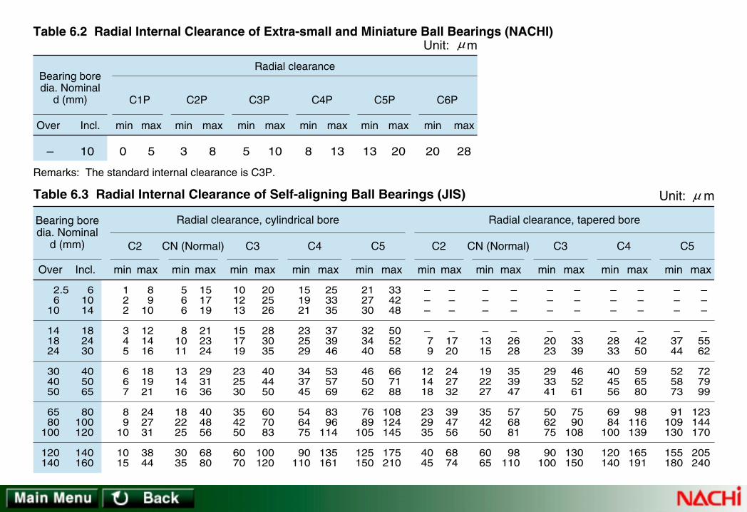
10 0 5 3 8 5 10 8 13 13 20 20 28–
Radial clearance
C1P C2P C3P C4P C5P C6P
Unit: mTable 6.2 Radial Internal Clearance of Extra-small and Miniature Ball Bearings (NACHI)
Remarks: The standard internal clearance is C3P.
Incl.Over min max min max min max min max min max min max
Bearing boredia. Nominal
d (mm)
µ
122
345
667
89
10
1015
89
10
121416
181921
242731
3844
566
81011
131416
182225
3035
151719
212324
293136
404856
6880
101213
151719
232530
354250
6070
202526
283035
404450
607083
100120
151921
232529
343745
546475
90110
253335
373946
535769
8396
114
135161
212730
323440
465062
7689
105
125150
334248
505258
667188
108124145
175210
– – –
– 79
121418
232935
4045
– – –
– 1720
242732
394756
6874
– – –
– 1315
192227
354250
6065
– – –
– 2628
353947
576881
98110
– – –
– 2023
293341
506275
90100
– – –
– 3339
465261
7590
108
130150
– – –
– 2833
404556
6984
100
120140
– – –
– 4250
596580
98116139
165191
– – –
– 3744
525873
91109130
155180
– – –
– 5562
727999
123144170
205240
61014
182430
405065
80100120
140160
2.56
10
141824
304050
6580
100
120140
Table 6.3 Radial Internal Clearance of Self-aligning Ball Bearings (JIS) Unit: m
Bearing boredia. Nominal
d (mm)
min max min max min max min max min max min max min max min max min max min maxOver Incl.
C2 CN (Normal) C3 C4 C5 C2 CN (Normal) C3 C4 C5
Radial clearance, cylindrical bore Radial clearance, tapered bore
µ

– 10 24
30 40 50
65 80
100
120 140 160
180 200 225
250 280 315
355 400 450
10 24 30
40 50 65
80 100 120
140 160 180
200 225 250
280 315 355
400 450 500
0 0 0
5 5
10
10 15 15
15 20 25
35 45 45
55 55 65
100 110 110
25 25 25
30 35 40
45 50 55
60 70 75
90 105 110
125 130 145
190 210 220
min max
20 20 20
25 30 40
40 50 50
60 70 75
90 105 110
125 130 145
190 210 220
45 45 45
50 60 70
75 85 90
105 120 125
145 165 175
195 205 225
280 310 330
min max
35 35 35
45 50 60
65 75 85
100 115 120
140 160 170
190 200 225
280 310 330
60 60 60
70 80 90
100 110 125
145 165 170
195 220 235
260 275 305
370 410 440
min max
50 50 50
60 70 80
90 105 125
145 165 170
195 220 235
260 275 305
370 410 440
75 75 75
85 100 110
125 140 165
190 215 220
250 280 300
330 350 385
460 510 550
min max
– 65 70
80 95
110
130 155 180
200 225 250
275 305 330
370 410 455
510 565 625
– 90 95
105 125 140
165 190 220
245 275 300
330 365 395
440 485 535
600 665 735
min max
C2 CN (Normal) C3 C4 C5
Radial clearance
Incl.Over
Table 6.4.1 Radial Internal Clearance of Cylindrical Roller Bearings with Cylindrical Bore (JIS)
Radial Internal Clearance of Cylindrical Roller Bearings
Unit: m
Bearing borediameter Nominal
d (mm)
µ
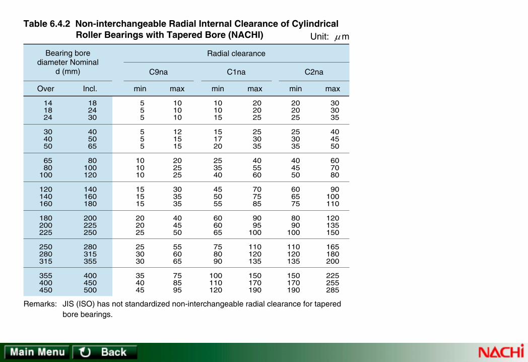
141824
304050
6580
100
120140160
180200225
250280315
355400450
182430
405065
80100120
140160180
200225250
280315355
400450500
555
555
101010
151515
202025
253030
354045
101010
121515
202525
303535
404550
556065
758595
min max
101015
151720
253540
455055
606065
758090
100110120
202025
253035
405560
707585
9095
100
110120135
150170190
min max
202025
253035
404550
606575
8090
100
110120135
150170190
303035
404550
607080
90100110
120135150
165180200
225255285
min max
C9na C2na
Radial clearance
Incl.Over
Table 6.4.2 Non-interchangeable Radial Internal Clearance of Cylindrical Roller Bearings with Tapered Bore (NACHI) Unit: m
C1na
Remarks: JIS (ISO) has not standardized non-interchangeable radial clearance for taperedbore bearings.
Bearing borediameter Nominal
d (mm)
µ

141824
304050
6580
100
120140160
180200225
250280315
355400450
500560630
710800900
182430
405065
80100120
140160180
200225250
280315355
400450500
560630710
800900
1000
101015
152020
303540
506065
708090
100110120
130140140
150170190
210230260
202025
303540
506075
95110120
130140150
170190200
220240260
280310350
390430480
min max
202025
303540
506075
95110120
130140150
170190200
220240260
280310350
390430480
353540
455565
80100120
145170180
200220240
260280310
340370410
440480530
580650710
min max
353540
455565
80100120
145170180
200220240
260280310
340370410
440480530
580650710
454555
607590
110135160
190220240
260290320
350370410
450500550
600650700
770860930
min max
454555
607590
110135160
190220240
260290320
350370410
450500550
600650700
770860930
606075
80100120
145180210
240280310
340380420
460500550
600660720
780850920
101011201220
min max
606075
80100120
145180210
240280310
340380420
460500550
600660720
780850920
101011201220
757595
100125150
180225260
300350390
430470520
570630690
750820900
100011001190
130014401570
min max
C2 C3 C4 C5
Radial clearance
Incl.Over
Unit: m
CN (Normal)
Table 6.5.1 Radial Internal Clearance of Spherical Roller Bearings with Cylindrical Bore (JIS)
Radial Internal Clearance of Spherical Roller Bearings
Bearing borediameter Nominal
d (mm)
µ

1824
304050
6580
100
120140160
180200225
250280315
355400450
500560630
710800900
2430
405065
80100120
140160180
200225250
280315355
400450500
560630710
800900
1000
1520
253040
505565
8090
100
110120140
150170190
210230260
290320350
390440490
2530
354555
7080
100
120130140
160180200
220240270
300330370
410460510
570640710
min max
2530
354555
7080
100
120130140
160180200
220240270
300330370
410460510
570640710
3540
506075
95110135
160180200
220250270
300330360
400440490
540600670
750840930
min max
3540
506075
95110135
160180200
220250270
300330360
400440490
540600670
750840930
4555
658095
120140170
200230260
290320350
390430470
520570630
680760850
96010701190
min max
4555
658095
120140170
200230260
290320350
390430470
520570630
680760850
96010701190
6075
85100120
150180220
260300340
370410450
490540590
650720790
870980
1090
122013701520
min max
6075
85100120
150180220
260300340
370410450
490540590
650720790
870980
1090
122013701520
7595
105130160
200230280
330380430
470520570
620680740
820910
1000
110012301360
150016901860
min max
C2 C3 C4 C5
Radial clearance
Incl.Over
Table 6.5.2 Radial Internal Clearance of Spherical Roller Bearings with Tapered Bore (JIS) Unit: m
CN (Normal)
Bearing borediameter Nominal
d (mm)
µ

141824
304050
6580
100
120140160
180200225
250280315
355400450
182430
405065
80100120
140160180
200225250
280315355
400450500
222
222
555
101010
101015
151515
202020
101010
121515
202525
303535
404550
556065
758595
101010
121515
202525
303535
404550
556065
758595
202025
253035
404550
606575
8090
100
110120135
150170190
202025
253035
404550
606575
8090
100
110120135
150170190
303035
404550
607080
90100110
120135150
165180200
225255285
353540
455055
708095
105115125
140155170
185205225
255285315
454550
556575
90105120
135150165
180200215
240265295
330370410
454550
556575
90105120
135150165
180200215
240265295
330370410
555560
708090
110125145
160180200
220240265
295325360
405455505
min max min max min max min max min max
C1 CN (Normal) C3 C4
Radial clearance
Incl.Over
Table 6.6 Radial Internal Clearance of Double-row and Duplex Tapered Roller Bearings with Cylindrical Bore (NACHI) Unit: m
C2
656570
8095
110
130155180
200225250
275305330
370410455
510565625
757580
95110130
150180205
230260285
315350380
420470520
585650720
min max
C5
Bearing borediameter Nominal
d (mm)
µ

101830
5080
120
183050
80120160
459
121824
111217
223038
min maxIncl.Over
Bearing borediameter Nominal
d (mm)
Table 6.7.1 Radial Internal Clearance ofDeep-groove Ball Bearings (BAS)
Table 6.7.2 Radial Internal Clearance of Cylindrical Roller Bearings (BAS)Unit: m
Note: (1)Remarks:
10 mm is included in this group.The value in this table is under the condition ofunloaded state.
Remarks: "Interchangeability" in this table meansinterchangeability between NACHI bearings only notwith other brand bearings.
Radial clearanceCM
Radial Internal Clearance of Bearings for Electric Motor
244050
6580
100
120140160
180
405065
80100120
140160180
200
152025
303535
405060
65
354045
506065
708595
105
min max
152025
303535
405060
65
303540
455560
658090
100
Incl.Over
Bearing borediameter Nominal
d (mm)
Unit: mRadial clearance
( 1 )
min max
Interchangeable CT Non-interchangeableCT
µ µ

[Continue→]
7.1 Bearing Ring and Rolling Elements7.1 Bearing Ring and Rolling ElementsBecause of high, repetitive stress to the rolling contact areas, fatigue phenomenon will occur to the bearing material after a duration ofoperation. Loading stress ultimately dislodges a surface section and the bearing fails. To delay the advent of material fatigue, bearing ringand rolling element materials should have the following properties: • High level of hardness• High rolling contact fatigue resistance• Good wear resistance• Dimensional stability• Good mechanical strengthStandard NACHI material for bearing rings and rolling elements is vacuum-degassed, high-carbon, chrome bearing steel. See Table 7.1.For applications requiring a higher degree of reliability, bearing steel using a vacuum-melting process or electroslag solution (ESR).The NACHI steel used for standard bearings is SUJ2 (JIS) steel. For large size bearings, SUJ3 or SUJ5 steels are used for hardenability.If impact resistance is required, SNCM series steel may be used (see Table 7.2).In addition to the above, high-speed steel may be used for bearings for applications requiring tolerance to high temperatures.Stainless steel may be used for bearings operating in a corrosive atmosphere.Ceramic materials may be used for special applications.
7. Materials for Rolling Contact Bearings7. Materials for Rolling Contact Bearings
A rolling contact bearing consist of one or more rings and rolling elements (which directly support the loads) and, usually, a cage whichkeeps the rolling elements at equal intervals. Both rolling and sliding movements occur between these parts.
7.2 Cage Material7.2 Cage MaterialMaterials for cages are required to have the following properties:• Good wear resistance• Dimensional stability• Good mechanical strength

[→Continue]
Table 7.1 High-Carbon Chrome Bearing Steel
Table 7.2 Case Hardening Steel
Table 7.3 High-Speed Steel
Table 7.4 Stainless Steel
Table 7.5 Cold Rolled Steel Strip and Cold Rolled Steel Sheet and Plate for Pressed Cage
Table 7.6 High Tensile Strength Brass Casting for Machined Cage
Table 7.7 Steel for Machined Cage
Cold-rolled steel (see Table 7.5) is used for pressed cages. High-tensile-strength brass castings or machined-steel are used formachined cages (see Tables 7.6 and 7.7). Polyamide resin are used depending on the type of bearing and the application.For selection of cage material, it is important to consider the operating conditions.Polyamide cages should not be used at temperatures above 120ºC or below -40ºC.Polyamide cages should not be used in vacuum because they become brittle due to dehydration.Polyamide cages may be affected by the use of specific lubricants.
Brass cages should not be used at temperatures in excess 300ºC.Brass cages are not suitable in Ammonia (e.g. in refrigeration) because Ammonia causes season cracking in brass.

0.17 ~ 0.230.17 ~ 0.230.12 ~ 0.180.18 ~ 0.23
0.18 ~ 0.230.17 ~ 0.22
0.15 ~ 0.350.15 ~ 0.350.15 ~ 0.350.15 ~ 0.35
0.15 ~ 0.350.15 ~ 0.35
≤ 0.030≤ 0.030≤ 0.030≤ 0.030
≤ 0.035≤ 0.035
≤ 0.030≤ 0.030≤ 0.030≤ 0.030
≤ 0.040≤ 0.040
0.40 ~ 0.701.60 ~ 2.004.00 ~ 4.50
–
0.40 ~ 0.701.65 ~ 2.00
0.40 ~ 0.650.40 ~ 0.650.70 ~ 1.000.90 ~ 1.20
0.40 ~ 0.600.40 ~ 0.60
SNCM220SNCM420SNCM815SCr420
86204320
JIS
SAE
C Si Mn P S Ni Cr
Chemical composition (%)SymbolStandard
Table 7.2 Case Hardening Steel
0.15 ~ 0.300.15 ~ 0.300.15 ~ 0.30
–
0.15 ~ 0.250.20 ~ 0.30
Mo
0.60 ~ 0.900.40 ~ 0.700.30 ~ 0.600.60 ~ 0.85
0.70 ~ 0.900.45 ~ 0.65
0.95 ~ 1.100.95 ~ 1.100.95 ~ 1.100.95 ~ 1.10
0.98 ~ 1.10
0.15 ~ 0.350.40 ~ 0.700.15 ~ 0.350.40 ~ 0.70
0.15 ~ 0.35
≤ 0.500.90 ~ 1.15≤ 0.500.90 ~ 1.15
0.25 ~ 0.45
≤ 0.025≤ 0.025≤ 0.025≤ 0.025
≤ 0.025
≤ 0.025≤ 0.025≤ 0.025≤ 0.025
≤ 0.025
1.30 ~ 1.600.90 ~ 1.201.30 ~ 1.600.90 ~ 1.20
1.30 ~ 1.60
≤ 0.08≤ 0.08
0.10 ~ 0.250.10 ~ 0.25
≤ 0.10
SUJ 2SUJ 3SUJ 4SUJ 5
52100
JIS
SAE
C Si Mn P S Cr Mo
Chemical composition (%)SymbolStandard
Table 7.1 High-Carbon Chrome Bearing Steel

≤ 0.10 0.13 ~ 0.20
≤ 0.12
SPB 1SPB 2
SPCC
C P
Chemical composition (%)Symbol
BAS
JIS
Standard
Table 7.5 Cold Rolled Steel Strip and Cold Rolled Steel Sheet and Plate for Pressed Cage
≤ 0.030≤ 0.030
≤ 0.040
S
≤ 0.030≤ 0.030
≤ 0.045
Mn
0.25 ~ 0.450.25 ~ 0.60
≤ 0.50
Si
≤ 0.04≤ 0.04
–
0.95 ~ 1.20SUS440CJIS
C P
Chemical composition (%)SymbolStandard
Table 7.4 Stainless Steel
≤ 0.040 16.00 ~ 18.00
Cr Mo
≤ 0.75
S
≤ 0.030
Mn
≤ 1.00
Si
≤ 1.00
0.77 ~ 0.85
≤ 0.25 ≤ 0.015M50AISI
C Si Mn P
Chemical composition (%)Symbol
Stan-dard
Table 7.3 High-Speed Steel
≤ 0.35 ≤ 0.015
S
3.75 ~ 4.25
Cr
4.00 ~ 4.50
Mo
0.90 ~ 1.10
V Ni
≤ 0.15
Cu
≤ 0.10
Co
≤ 0.25
W
≤ 0.25

55.0 ~ 62.0
55.0 ~ 60.055.0 ~ 60.0
Cu
Chemical composition (%)
Table 7.6 High Tensile Strength Brass Casting for Machined Cage
Mn
2.0 ~ 4.0
≤ 1.5 0.1 ~ 3.5
HBsCR
HBsC1HBsC2
Symbol
BAS
JIS
Standard
33.0 ~ 37.0
Residue30.0 ~ 42.0
Zn Fe
0.5 ~ 1.5
0.5 ~ 1.50.5 ~ 2.0
AI
0.1 ~ 1.0
0.5 ~ 1.50.5 ~ 2.0
Sn
0.1 ~ 1.0
≤ 1.0 ≤ 1.0
Ni
≤ 1.0
≤ 1.0≤ 1.0
Pb
0.1 ~ 1.0
≤ 0.4≤ 0.4
Si
≤ 0.2
≤ 0.1≤ 0.1
Others
≤ 1.0
––
JIS 0.22 ~ 0.28
C
Chemical composition (%)
Table 7.7 Steel for Machined Cage
S25C
Symbol
0.15 ~ 0.35
Si P
≤ 0.030
S
≤ 0.0350.30 ~ 0.60
MnStandard

8.1 Fits and Clearance8.1 Fits and Clearance
8.2 Pr8.2 Preload and Rigidityeload and Rigidity
8.3 Shaft and Housing Selection8.3 Shaft and Housing Selection
8.4 Sealing Devices8.4 Sealing Devices
8.5 Lubrication8.5 Lubrication
8.6 Speed Limits8.6 Speed Limits
8.7 Friction and T8.7 Friction and Temperaturemperature Risee Rise
8.8 Mounting and Dismounting8.8 Mounting and Dismounting
8. Application of Bearings8. Application of Bearings

8.1.1 Impor8.1.1 Importance of Fittance of Fit
To get the best performance from a rolling contact bearing, the fit between the inner ring and shaft, and outer ring and housing mustbe correct. If the mating surfaces lack interference, the bearing ring may move circumferentially on the shaft or in the housing. Thisphenomenon is called creep. Once mating surfaces start to creep, the bearing ring will begin to wear excessively and the shaft and/orhousing may be damaged. Abrasive debris may enter the bearing to cause abnormal heating or vibration.Creep is often impossible to prevent by mere fastening of the bearing in an axial direction. To prevent creep, the bearing rings thatsupport the rotating load must be provided with necessary interference. The bearing rings that support stationary load normally do notrequire interference unless contact corrosion from vibration is a concern.
8. Application of Rolling Contact Bearings8. Application of Rolling Contact Bearings
8.1 Fits and Clearance8.1 Fits and Clearance
8.1.2 Selection of Fit8.1.2 Selection of Fit
To select the most appropriate fit, the following items must be considered:• direction of load• characteristics of load• magnitude of load• temperature conditions• mounting, and dismounting conditions
For general recommendations see Table 8.1.For mounting bearings in a thin-walled housing or on a hollow shaft, large interference than normal must be provided.Split-housing applications requiring high precision or tight housing bore fits are not recommended.(A split housing may cause the outerring to deform).For application of bearings subjected to vibration, an interference fit should be applied to both inner and outer rings.Tables 8.2 through 8.14 describe general fit recommendations. For fits not covered by these tables, please contact NACHI.

Table 8.1 Fits vs. Load Characteristics
Table 8.2.1 Bearing Bore (1) Fits for Radial Bearings
Table 8.2.2 Bearing Outside Diameter (1) Fits for RadialBearings
Table 8.3.1 Bearing Bore or Center Washer Bore (1) Fitsfor Thrust Bearings
Table 8.3.2 Bearing Outside Diameter (1) Fits for ThrustBearings
Table 8.4 Shaft Tolerances (1) for Radial Bearings
Table 8.5 Shaft Tolerances for Thrust Bearings
Table 8.6 Housing Bore Tolerances (1) for Radial Bearings(Except Inch-series Tapered Roller Bearings)
Table 8.7 Housing Bore Tolerances for Thrust Bearings
Table 8.8.1 For Bearings with ABMA Classes 4 and 2Table 8.8.2 For Bearings with ABMA Classes 3 and 0
Fits of Inch Series Tapered Roller Bearings with Shafts
Table 8.9.1 For Bearings with ABMA Classes 4 and 2Table 8.9.2 For Bearings with ABMA Classes 3 and 0
Fits of Inch Series Tapered Roller Bearings with Housings
Table 8.10.1 Inner Ring with ShaftTable 8.10.2 Outer Ring with Housing
Amounts of Fits: Radial Bearingswith Tolerance JIS Class 0 (ISO Normal Class)
Table 8.11.1 Inner Ring with ShaftTable 8.11.2 Outer Ring with Housing
Amounts of Fits: Radial Bearingswith Tolerance JIS (ISO) Class 6
Table 8.12.1 Inner Ring with ShaftTable 8.12.2 Outer Ring with Housing
Amounts of Fits: Radial Bearingswith Tolerance JIS (ISO) Class 5
Table 8.13.1 Inner Ring with ShaftTable 8.13.2 Outer Ring with Housing
Amounts of Fits: Radial Bearingswith Tolerance JIS (ISO) Class 4
Amounts of Fits: Thrust Bearingswith Tolerance JIS (ISO) Class 0
Table 8.14.1 Shaft Washer or Center Washer with ShaftTable 8.14.2 Housing Washer with Housing

Rotating condition Type of loadLoad
conditions Inner ring Outer ringFit
Indeterminatedirection load
Interference fit Loose fit
Interference fit Interference fitRotating or
Non-rotatingLoad direction not constant because offluctuation unbalanced load
Table 8.1 Fits vs. Load Characteristics
Non-rotating
Non-rotating
inner ring
outer ring
outer ring
inner ring
Rotating
Rotating
Rotatinginnerring load
Stationaryouterring load
Loose fit Interference fit
Rotatingouterring load
Stationaryinnerring load

j 5j 6
js 6h 5
k 5k 6
m 5m 6n 6p 6r 6
h 4––– m 5 k 4 js 4 h 5 –
h 5h 6
g 5g 6Class 0, class 6
Class 5, class 4
For rotating inner ring load and indeterminate direction loadFor rotatingouter ring load
Fit class vs. load typeBearing toleranceclass
Table 8.2.1 Bearing Bore (1) Fits for Radial Bearings
Bearing toleranceclass
P 7K 6K 7G 7–
––K 5 – – M 5
Class 0, class 6
Class 5, class 4
For rotating inner ring load For rotating outer ring load
Fit class vs. load type
Table 8.2.2 Bearing Outside Diameter (1) Fits for Radial Bearings
J 6J 7
J 6J 7
Js 5
H 6H 7
H 5
For indeterminate direction load
M 7
–
N 7
–
M 7

Bearing toleranceclass
n 6Class 0
For centric axial load
Fit class vs. load type
Table 8.3.1 Bearing Bore or Center Washer Bore (1) Fits for Thrust Bearings
j 6js 6
j 6js 6
For composite load (spherical roller thrust bearing)
m 6 k 6
Bearing toleranceclass
M 7Class 0
For centric axial load
Fit class vs. load type
Table 8.3.2 Bearing Outside Diameter (1) Fits for Thrust Bearings
For composite load (spherical roller thrust bearing)
H 7–
Note: (1) These dimensional fits are based on JIS B 1514.

For all shaft diameters g6
When high precision is required, adopt g5 and h5 respectively. For large bearings, f6 is adopted because of easy bearing movement in axial direction.
Driven wheel
For all shaft diameters h6 Tension pully, rope sheave
Operating conditions
Rotatingouter ring
load
Shaft diameter (mm)
RemarksTolerancesymbols
Examples of application(Reference)Bell bearings Spherical roller
bearings
Cylindrical rollerbearingsTapered rollerbearings
Bearings with cylindrical bore
Table 8.4 Shaft Tolerances (1) for Radial Bearings
When the inner ring is required to move on the shaft easily
When the inner ring is required to move on the shaft easily
Remarks: Heavy load P > 0.12Cr , Normal Load 0.06Cr < P ≤ 0.12Cr , Light Load P ≤ 0.06Cr Cr: Basic Dynamic Load RatingNote: (1) Shaft tolerances in this table are applied to solid steel shaft for bearings with tolerance class 0 and 6.
(1/3)

underand incl.
OverIncl.
18 100
OverIncl.
18 100
OverIncl.
100 200
OverIncl.
100 200
OverIncl.
40 140
OverIncl.
140 200
18
underand incl.18
– –
–
–
–
–
–
–
–
–
–
–
–
–
–
–
h5
j6
k6
m6
j5
k5
m5
m6
n6
p6
r6280 Over
140 Over200 Over
n6
p6
r6
When high precision is required, adopt j5, k5 and m5 instead of j6, k5 and m6 respectively
Electrical appliance,machining tool, pump,blower, haulage car
Normal loador
heavy load
Compositeload
The tolerances of k6 and m6 instead of k5 and m5 can be used for single row tapered roller bearings and single row angular contact ball bearings.
Electric motor, turbine, pump, internal combustion engine, wood working machine, bearing application in general.
Light loador
fluctuatingload
Rotatinginner ringload or
indeterminatedirection
load
underand incl.40
OverIncl.
40100
OverIncl.
100 140
OverIncl.
140 200
OverIncl.
200 400
underand incl.40
OverIncl.
4065
OverIncl.
65 100
OverIncl.
100 140
OverIncl.
140 200
OverIncl.
50 140
OverIncl.
50 100
OverIncl.
140 200
OverIncl.
100 140
underand incl.40
A bearing with an internal clearance larger than the normal clearance is required
Axles of locomotive and passenger train, traction motor
Operating conditions
Shaft diameter (mm)
RemarksTolerancesymbols
Examples of application(Reference)Bell bearings Spherical roller
bearings
Cylindrical rollerbearingsTapered rollerbearings
Table 8.4 Shaft Tolerances (1) for Radial Bearings
Remarks: Heavy load P > 0.12Cr , Normal Load 0.06Cr < P ≤ 0.12Cr , Light Load P ≤ 0.06Cr Cr: Basic Dynamic Load RatingNote: (1) Shaft tolerances in this table are applied to solid steel shaft for bearings with tolerance class 0 and 6.
(2/3)

250 under and incl.
250 Over
j6
js6, j6Centric axial load – –
h10/IT7 instead of h9/IT5 can be used for power transmission shaft. IT5 and IT7 mean the form error (out of roundness, taper) should be limited within the tolerance ranges of IT5 and IT7
For all load condition For all shaft conditionRailroad car axle, bearingapplication in generalh9/IT5
Bearing with tapered bore (with sleeve)
Operating conditions
Shaft diameter (mm)
RemarksTolerancesymbols
Examples of application(Reference)Bell bearings Spherical roller
bearings
Cylindrical rollerbearingsTapered rollerbearings
Table 8.4 Shaft Tolerances (1) for Radial Bearings
Remarks: Heavy load P > 0.12Cr , Normal Load 0.06Cr < P ≤ 0.12Cr , Light Load P ≤ 0.06Cr Cr: Basic Dynamic Load RatingNote: (1) Shaft tolerances in this table are applied to solid steel shaft for bearings with tolerance class 0 and 6.
(3/3)

250 under and incl.
250 Over
250 under and incl.
250 Over
200 under and incl.
200 Over 400 Incl.
400 Over
Shaft diameter (mm)
j6
js6, j6
j6
js6, j6
k6
m6
n6
Tolerance symbols
Centric axial load
Operating conditions
(Thrust ball bearings and spherical roller thrust bearings)
Composite load (Spherical roller thrust bearings)
Rotating outer ring load
Rotation inner ring load orindeterminate direction load
Table 8.5 Shaft Tolerances for Thrust Bearings
Spherical roller thrust bearing;When housing is located in radialdirection by another bearing.
Thrust ball bearing
Stationary outer ring load orindeterminate direction load
Rotating outer ring load
When high accuracy is not required, radial clearancewill be provided between outer ring (housingwasher)/aligning housing washer and housing
0.001D is recommended as a radial clearancebetween outer ring and housing. D: outsidediameter of housing washer
In case when the radial load is comparativelylarge, bearing application in general
–
–
H8
K7M7
H7J7
Composite load (Spherical roller thrust bearings)
Centric axial load (All thrust bearings)
Tolerancesymbols
Operating conditions Remarks
Table 8.7 Housing Bore Tolerances for Thrust Bearings

When a heavy load is applied to athin-walled housing or impact load
Normal load or heavy load
Light load or fluctuating load
Heavy impact load
Heavy load or normal load; Whenthe outer ring is not required tomove in axial direction
Normal load or light load; When itis desirable that the outer ring canbe moved in axial direction
Impact load; When no-loadcondition occurs instantaneously
All kinds of load
Normal load or light load
When thermal conduction throughthe shaft is caused
N7
P7
M7
K7
J7
H7
H8
G7
Outer ring can notbe moved in axial direction.
Outer ring can not bemoved in axialdirection as a rule.
Outer ring can bemoved in axialdirection.
Outer ring can bemoved easily inaxial direction.
Automotive wheel (ball bearing)
Automotive wheel (roller bearing)
Conveyer roller, pulley, tension pulley
Traction motor
Electric motor, pump, crank shaft
Electric motor, pump, crank shaft
Railroad car axle
Railroad car axle, bearing applicationin general
Gear transmission
Paper mill (Drying cylinder)
Rotating outerring load
Indeterminatedirection load
Rotating innerring load
Table 8.6 Housing Bore Tolerances (1) for Radial Bearings (Except Inch-series Tapered Roller Bearings)
Operating conditions Tolerancesymbols
Outer ring movement Examples of application (Reference)
Note: (1) The tolerances in this table are applied to cast iron or steel housing for bearings with tolerance class 0 and 6. Tighter fit is adopted for light alloy housing. (2) Outer ring of non-separable bearing
Monoblockhousing
Monoblockor split
housing
(2)
(1/2)

Fluctuating load; When extremelyaccurate rotation and high rigidityare required
Indeterminate direction light load;When extremely accurate rotationis required.
When extremely accurate rotation isrequired and it is desirable that the outerring can be moved in axial direction.
N6
M6
K6
J6
Outer ring can notbe moved in axialdirection.
Outer ring can not bemoved in axialdirection as a rule.
Outer ring can bemoved in axialdirection.
Main shaft of grinding machine, ball bearing ongrinding wheel side High speed centrifugalcompressor, clamping side bearing
Main shaft of machine tool (roller bearing outside diameter is under and including 125 mm)
Main shaft of machine tool(roller bearing, outside diameter is over 125 mm)
Main shaft of grinding machine, ball bearing ondriving side High speed centrifugal compressor,floating side bearing
When extremelyhigh accuracy is
required
Table 8.6 Housing Bore Tolerances (1) for Radial Bearings (Except Inch-series Tapered Roller Bearings)
Operating conditions Tolerancesymbols Outer ring movement Examples of application (Reference)
Note: (1) The tolerances in this table are applied to cast iron or steel housing for bearings with tolerance class 0 and 6. Tighter fit is adopted for light alloy housing. (2) Outer ring of non-separable bearing
Monoblockhousing
(2)
(2/2)

+13+25+51+76
+13+25+51+76
+13+25+51+76
+13+25+51+76
0000
0000
0000
0000
+ 38+ 64+127+191
+ 64
+381
+ 13+ 25+ 51+ 76
0000
+ 26+ 38+ 76+114
+ 38
+305
0000
– 13– 25– 51– 76
38T64T
127T191T
64T
381T
13T25T51T76T
0 0 0 0
12T13T25T38T
25T
229T
13L25L51L76L
26L51L
102L152L
76.2304.8609.6914.4
76.2304.8609.6914.4
76.2304.8609.6914.4
76.2304.8609.6914.4
–76.2
304.8609.6
–76.2
304.8609.6
–76.2
304.8609.6
–76.2
304.8609.6
Normal loadNo impact
Heavy loadHigh speedrotationImpact load
Normal loadNo impact
Non-ground shaft(When the innerring is notrequired to movein axial direction.)
Ground shaft(When the innerring is requiredto move in axialdirection)
Normal loadNo impact
Over Incl. High Low High Low Max Min
Amounts (1)Shaft diameter deviationBearing boredeviation
Bearing bore diameterNominal d (mm)
Operating conditions
(2)
Table 8.8.1 For Bearings with ABMA Classes 4 and 2
Note:
Unit: m
Table 8.8 Fits of Inch Series Tapered Roller Bearings with Shafts
Rota-tinginnerringload
Rota-tingouterringload
(1) T: Tight fit L: Loose fit (2) Mean amounts of tight fits are d/2000 mm
µ

Note:
+13+25+38
+13+13+25+38
+13+25+38
000
0000
000
+ 38+ 64+102
+ 13+ 64+102
+18+38+63
+18+38+63
31T64T
102T
31T64T
102T
5T13T25T
5T13T25T
304.8609.6914.4
76.2304.8609.6914.4
304.8609.6914.4
–304.8609.6
–76.2
304.8609.6
–304.8609.6
Main shaft ofprecisionmachine tool
Heavy loadHigh speedrotationImpact load
Over Incl. High Low High Low Max Min
Amounts (1)Shaft diameter deviationBearing boredeviation
Bearing bore diameterNominal d (mm)
Operating conditions
(2)
Table 8.8.2 For Bearings with ABMA Classes 3 and 0
Main shaft ofprecisionmachine tool
Unit: m
Rota-tinginnerringload
Rota-tingouterringload
(1) T: Tight fit L: Loose fit (2) Mean amounts of tight fits are d/4000mm (3) This table is not applied to the bearing with tolerance class 0 whose bore diameter is over 241.3 mm
µ

+25+25+25+51+76
+25+25+25+51+76
+25+25+25+51+76
+25+25+25+51+76
00000
00000
00000
00000
+ 76+ 76+ 76+152+229
+ 25+ 25+ 51+ 76+127
– 13– 25– 25– 25– 25
– 13– 25– 25– 25– 25
+ 50+ 50+ 50+102+152
000
+ 26+ 51
– 39– 51− 51– 76–102
– 39– 51– 51– 76–102
25L25L25L51L76L
25T25T25T25T25T
64T76T76T
127T178T
64T76T76T
127T178T
76L76L76L
152L229L
25L25L51L76L
127L
13T25T25T25T25T
13T25T25T25T25T
76.2127.0304.8609.6914.4
76.2127.0304.8609.6914.4
76.2127.0304.8609.6914.4
76.2127.0304.8609.6914.4
–76.2
127.0304.8609.6
–76.2
127.0304.8609.6
–76.2
127.0304.8609.6
–76.2
127.0304.8609.6
Floating side orClamping side
Outer ring location inaxial direction can beadjusted
Over Incl. High Low High Low Max Min
Amounts (1)Bearing outsidediameter deviation
Housing borediameter deviation
Bearing outside diameterNominal D (mm)Operating conditions
Table 8.9.1 For Bearings with ABMA Classes 4 and 2 Unit: m
Table 8.9 Fits of Inch Series Tapered Roller Bearings with Housings
Outer ring location inaxial direction cannot be adjusted
Outer ring location inaxial direction cannot be adjusted
Rotatinginnerringload
Rotatingouterringload
Note: (1) T: Tight fit L: Loose fit
µ

+13+13+25+38
+13+13+25+38
+13+13+25+38
+13+13+25+38
+13+13+25+38
0000
0000
0000
0000
0000
+38+38+64+89
+25+25+51+76
+13+25+25+38
0000
–13–13–13–13
+26+26+38+51
+13+13+25+38
0000
–12–25–26–38
–25–38–39–51
13L13L13L13L
0 0 0 0
13T13T25T38T
25T38T51T76T
38T51T64T89T
38L38L64L89L
25L25L51L76L
13L25L25L38L
0 0 0 0
13T13T13T13T
152.4304.8609.6914.4
152.4304.8609.6914.4
152.4304.8609.6914.4
152.4304.8609.6914.4
152.4304.8609.6914.4
–152.4304.8609.6
–152.4304.8609.6
–152.4304.8609.6
–152.4304.8609.6
–152.4304.8609.6
Clamping side
Outer ring location inaxial direction can beadjusted
Table 8.9.2 For Bearings with ABMA Classes 3 and 0 Unit: m
Outer ring location inaxial direction cannot be adjusted
Normal loadOuter ring location inaxial direction cannot be adjusted
Floating side
Rotatinginnerringload
Rotatingouterringload
Note: (1) T: Tight fit L: Loose fit (2) This tables is not applied to the bearing with tolerance class 0 whose bore diameter is over 304.8 mm.
Over Incl. High Low High Low Max Min
Amounts (1)Bearing outsidediameter deviation
Housing borediameter deviation
Bearing outside diameterNominal D (mm)Operating conditions
µ

36
10
18305080
120140160
180200225
250280
315355
400450
61018
305080
120
140160180
200225250
280315
355400
450500
Over Incl. High
Nominal
diameter
(mm)
Table 8.10.1 Inner Ring with Shaft Unit: m
– 8– 8– 8
–10–12–15–20
–25
–30
–35
–40
–45
–––
–323948
58
67
–
–
–
–––
– 91113
15
17
–
–
–
––17
21253038
46
54
–
–
–
––1
2223
3
4
–
–
–
111213
15182126
–
–
–
–
–
223
4579
–
–
–
–
–
8 8 8
10121520
25
30
35
40
45
5 6 8
9111315
18
20
23
25
27
Low Max Min Max Min Max Max Max Max
Single planemean borediameterdeviationof bearing
Tight Tight Loose Loose LooseTight Tight Tight
m5 k5 j5 h5
4 3 2
3 3 5 8
11
15
18
22
25
91114
16202327
32
35
40
43
47
Max Max
g5
Shaft with tolerance grade IT5
mpd
000
0000
0
0
0
0
0
µ
Table 8.10 Amounts of Fits: Radial Bearings with Tolerance JIS Class 0 (ISO Normal Class)
(1/2)
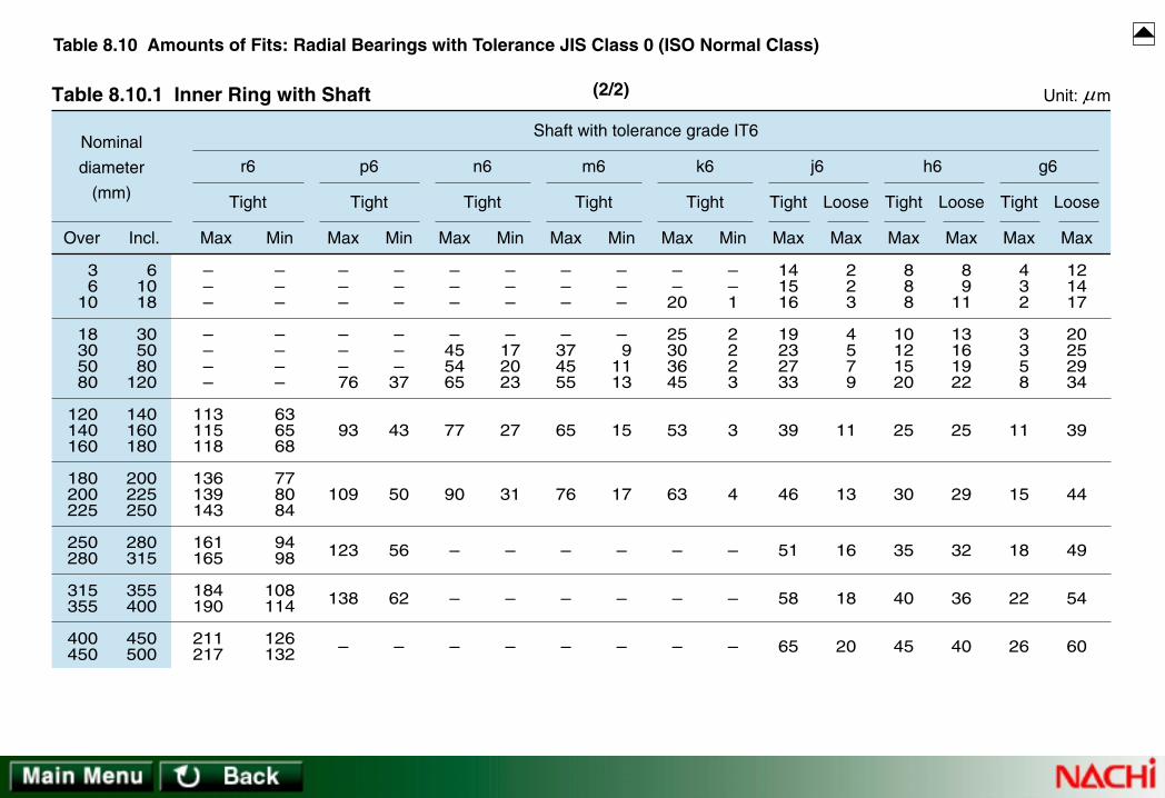
36
10
18305080
120140160
180200225
250280
315355
400450
61018
305080
120
140160180
200225250
280315
355400
450500
Over Incl.
Nominal
diameter
(mm)
Table 8.10.1 Inner Ring with Shaft Unit: m
LooseLooseLoose TightTightTight
–––
––––
113115118
136139143
161165
184190
211217
–––
––––
63 65 68
77 80 84
94 98
108114
126132
Max Min
Tight
r6
–––
–––
76
93
109
123
138
–
–––
–––37
43
50
56
62
–
Max Min
Tight
p6
–––
–455465
77
90
–
–
–
–––
–172023
27
31
–
–
–
Max Min
Tight
n6
–––
–374555
65
76
–
–
–
–––
– 91113
15
17
–
–
–
Max Min
Tight
m6
––20
25303645
53
63
–
–
–
––1
2223
3
4
–
–
–
Max Min
Tight
k6
141516
19232733
39
46
51
58
65
2 2 3
4 5 7 9
11
13
16
18
20
Max Max
j6
8 8 8
10121520
25
30
35
40
45
8 911
13161922
25
29
32
36
40
Max Max
h6
4 3 2
3 3 5 8
11
15
18
22
26
121417
20252934
39
44
49
54
60
Max Max
g6
Shaft with tolerance grade IT6
µ
Table 8.10 Amounts of Fits: Radial Bearings with Tolerance JIS Class 0 (ISO Normal Class)
(2/2)

61018
305080
120150180
250315400
101830
5080
120
150180250
315400500
Over Incl.
Nominal
diameter
(mm)
Table 8.10.2 Outer Ring with Housing Unit: m
000
000
000
000
– 8– 8– 8
–11–13–15
–18–25–30
–35–40–45
455
666
777
777
131417
212631
364352
606978
High Low Max Max
J6
Housing with tolerance grade IT6
LooseTight Tight
7 911
131518
212124
272932
101011
141719
222935
404753
Max Max
K6
LooseTight
000
000
000
000
171922
273237
435059
677685
H6
Loose
MaxMax
mpD
Single plane meanoutside diameter
deviationof bearing
µ
Table 8.10 Amounts of Fits: Radial Bearings with Tolerance JIS Class 0 (ISO Normal Class)
(1/2)

61018
305080
120150180
250315400
101830
5080
120
150180250
315400500
Over Incl.
Nominal
diameter
(mm)
Table 8.10.2 Outer Ring with Housing Unit: m
242935
425159
686879
8898
108
135
689
10 33
110
Max Min
Tight Tight Tight Tight Tight Tight
P7
Housing with tolerance grade IT7
192328
333945
526060
667380
4 3 2
3 4 5
61316
212428
N7
Loose
MaxMax
151821
253035
404046
525763
8 8 9
111315
182530
354045
M7
Loose
MaxMax
101215
182125
282833
364045
131415
182225
303743
515763
K7
Loose
MaxMax
7 8 9
111213
141416
161820
161821
253137
445160
717988
J7
Loose
MaxMax
000
000
000
000
232630
364350
586576
8797
108
H7
Loose
MaxMax
5 6 7
91012
141415
171820
28 32 37
45 53 62
72 79 91
104115128
G7
Loose
MaxMin
µ
Table 8.10 Amounts of Fits: Radial Bearings with Tolerance JIS Class 0 (ISO Normal Class)
(2/2)

36
10
18305080
120140160
180200225
61018
305080
120
140160180
200225250
Over Incl.
Nominal
diameter
(mm)
Table 8.11.1 Inner Ring with Shaft Unit: m
000
0000
0
0
– 7– 7– 7
– 8–10–12–15
–18
–22
–––
–303643
51
59
–––
– 91113
15
17
––16
19232733
39
46
––1
2223
3
4
101112
13161821
–
–
223
4579
–
–
7 7 7
8101215
18
22
5 6 8
9111315
18
20
High Low Max Min Max Min Max Max Max Max
Tight Tight Tight TightTight Loose Loose Loose
m5 k5 j5 h5
321
1123
4
7
91114
16202327
32
35
Max Max
g5
Shaft with tolerance grade IT5Single planemean borediameterdeviationof bearing
mpd
µ
Table 8.11 Amounts of Fits: Radial Bearings with Tolerance JIS (ISO) Class 6
(1/2)

36
10
18305080
120140160
180200225
61018
305080
120
140160180
200225250
Over Incl.
Nominal
diameter
(mm)
Table 8.11.1 Inner Ring with Shaft Unit: m
Loose Loose Loose
–––
––––
106108111
128131135
–––
––––
63 65 68
77 80 84
Max Min
Tight
r6
–––
–––
74
86
101
–––
–––37
43
50
Max Min
Tight
p6
–––
–435160
70
82
–––
–172023
27
31
Max Min
Tight
n6
–––
–354250
58
68
–––
– 91113
15
17
Max Min
Tight
m6
––19
23283340
46
55
––1
2223
3
4
Max Min
Tight Tight TightTight
k6
131415
17212428
32
38
2 2 3
4 5 7 9
11
13
Max Max
j6
7 7 7
8101215
18
22
8 911
13161922
25
29
Max Max
h6
321
1123
4
7
121417
20252934
39
44
Max Max
g6
Shaft with tolerance grade IT6
µ
Table 8.11 Amounts of Fits: Radial Bearings with Tolerance JIS (ISO) Class 6
(2/2)

61018
305080
120150180
250315
101830
5080
120
150180250
315400
Over Incl.
Nominal
diameter
(mm)
Table 8.11.2 Outer Ring with Housing Unit: m
000
000
000
00
– 7– 7– 8
– 9–11–13
–15–18–20
–25–28
455
666
777
77
121316
192429
333642
5057
High Low Max Max
J6
Housing with tolerance grade IT6
LooseTight Tight Tight
7 911
131518
212124
2729
9 910
121517
192225
3035
Max Max
K6
Loose
000
000
000
00
161821
253035
404349
5764
H6
Loose
MaxMax
mpD
Single plane meanoutside diameter
deviationof bearing
µ
Table 8.11 Amounts of Fits: Radial Bearings with Tolerance JIS (ISO) Class 6
(1/2)

61018
305080
120150180
250315
101830
5080
120
150180250
315400
Over Incl.
Nominal
diameter
(mm)
Table 8.11.2 Outer Ring with Housing Unit: m
242935
425159
686879
8898
2 4 6
81011
131013
1113
Max Min
Tight TightTightTightTightTight
P7
Housing with tolerance grade IT7
192328
333945
526060
6673
3 2 1
1 2 3
3 6 6
1112
N7
Loose
MaxMax
151821
253035
404046
5257
7 7 8
91113
151820
2528
M7
Loose
MaxMax
101215
182125
282833
3640
121314
162023
273033
4145
K7
Loose
MaxMax
7 8 9
111213
141416
1618
151720
232935
414450
6167
J7
Loose
MaxMax
000
000
000
00
222529
344148
555866
7785
H7
Loose
MaxMax
5 6 7
91012
141415
1718
27 31 36
43 51 60
69 72 81
94103
G7
Loose
MaxMin
µ
Table 8.11 Amounts of Fits: Radial Bearings with Tolerance JIS (ISO) Class 6
(2/2)
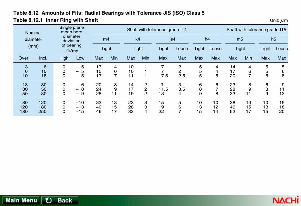
36
10
183050
80120180
61018
305080
120180250
000
000
000
– 5– 5– 5
– 6– 8– 9
–10–13–15
131517
202428
334046
4 6 7
8 911
131517
Over Incl. High Low Max Min
Tight
m4Nominal
diameter
(mm)
Shaft with tolerance grade IT4
Table 8.12.1 Inner Ring with Shaft Unit: m
Table 8.12 Amounts of Fits: Radial Bearings with Tolerance JIS (ISO) Class 5
Max Max
h5
5 6 8
91113
151820
5 5 5
6 8 9
101315
101011
141719
232833
111
222
334
Max Min
Tight TightTightTight Loose Loose Loose
k4
Max Max
js4
2 2 2.5
3 3.54
5 6 7
7 7
7.5
9 11.513
15 19 22
Max Max
h4
141720
232833
384652
4 6 7
8 911
131517
Max Min
Tight
m5
5 5 5
6 8 9
101315
4 4 5
6 7 8
101214
Shaft with tolerance grade IT5Single planemean borediameterdeviationof bearing
mpd
µ

Table 8.12 Amounts of Fits: Radial Bearings with Tolerance JIS (ISO) Class 5
61018
305080
120150180
250315
101830
5080
120
150180250
315400
000
000
000
00
– 5– 5– 6
– 7– 9–10
–11–13–15
–18–20
Over Incl. High Low
Nominal
diameter
(mm)
Housing with tolerance grade IT5
Table 8.12.2 Outer Ring with Housing Unit: m
Max Max
H5
000
000
000
00
111315
182225
293135
4145
LooseTight
Max Max
Js5
3 4
4.5
5.5 6.5 7.5
9 9
10
11.512.5
8 9
10.5
12.515.517.5
20 22 25
29.532.5
LooseTight
Max Max
K5
5 6 8
91013
151518
2022
6 7 7
91212
141617
2123
LooseTight
Max Max
M5
101214
161923
272731
3639
111
232
244
56
LooseTightmpD
Single plane meanoutside diameter
deviationof bearing
µ

36
10
183050
80120180
61018
305080
120180250
000
000
000
– 4– 4– 4
– 5– 6– 7
– 810
–12
121416
192226
313743
4 6 7
8 911
131517
Over Incl. High Low Max Min
Tight
m4Nominal
diameter
(mm)
Shaft with tolerance grade IT4
Table 8.13.1 Inner Ring with Shaft Unit: m
Table 8.13 Amounts of Fits: Radial Bearings with Tolerance JIS (ISO) Class 4
Max Max
h5
5 6 8
91113
151820
4 4 4
5 6 7
81012
9 910
131517
212530
111
222
334
Max Min
Tight
k4
Max Max
js4
2 2 2.5
3 3.54
5 6 7
6 6 6.5
8 9.5
11
13 16 19
Max Max
h4
131619
222631
364349
4 6 7
8 911
131517
Max Min
TightTight Loose Loose LooseTight Tight
m5
4 4 4
5 6 7
81012
4 4 5
6 7 8
101214
Shaft with tolerance grade IT5Single planemean borediameterdeviationof bearing
mpd
µ

Table 8.13 Amounts of Fits: Radial Bearings with Tolerance JIS (ISO) Class 4
61018
305080
120150180
250315
101830
5080
120
150180250
315400
000
000
000
00
– 4– 4– 5
– 6– 7– 8
– 9–10–11
–13–15
Over Incl. High Low
Nominal
diameter
(mm)
Housing with tolerance grade IT5
Table 8.13.2 Outer Ring with Housing Unit: m
Max Max
H5
000
000
000
00
101214
172023
272831
3640
LooseTight
Max Max
Js5
3 4
4.5
5.5 6.5 7.5
9 9
10
11.512.5
7 8
9.5
11.513.515.5
18 19 21
24.527.5
LooseTight
Max Max
K5
5 6 8
91013
151518
2022
5 6 6
81010
121313
1618
LooseTight
Max Max
M5
101214
161923
272731
3639
000
110
010
01
LooseTightmpD
Single plane meanoutside diameter
deviationof bearing
µ

61018
305080
120180250
315400
101830
5080
120
180250315
400500
000
000
000
00
– 8– 8–10
–12–15–20
–25–30–35
–40–45
Over Incl. High Low
Nominal
diameter
(mm)
Shaft with tolerance grade IT6
Table 8.14.1 Shaft Washer or Center Washer with Shaft Unit: m
Table 8.14 Amounts of Fits: Thrust Bearings with Tolerance JIS (ISO) Class 0
Max Max
j6
151619
232733
394651
5865
2 3 4
5 7 9
111316
1820
LooseTight
Max Min
k6
182025
303645
5363–
––
112
223
34–
––
Tight
Max Min
m6
–––
–––
–7687
97–
–––
–––
–1720
21–
Tight
Max Min
n6
–––
–––
–––
–125
–––
–––
–––
–40
Tight
Single plane mean borediameter deviation
of bearingmpd
µ

Table 8.14 Amounts of Fits: Thrust Bearings with Tolerance JIS (ISO) Class 0
101830
5080
120
180250315400
183050
80120180
250315400500
000
000
0000
–11–13–16
–19–22–25
–30–35–40–45
Over Incl. High Low
Nominal
diameter
(mm)
Housing with tolerance grade IT7
Table 8.14.2 Housing Washer with Housing Unit: m
Max Max
H7
000
000
0000
293441
495765
768797
108
LooseTight
Max Max
M7
182125
303540
46525763
111316
192225
30354045
LooseTightmpD
Single plane mean outsidediameter deviation
of bearing
µ

8.1.3 Calculating Fits8.1.3 Calculating Fits
The fits for bearings are often determined empirically according to Table 8.1 through Table 8.14. These tables are NOT to be used forthe following cases:• If special materials are used for interfaces.• If a hollow shaft is used.• For high-precision applications.
(1) Reduction of Interference due to Bearing LoadWhen load is applied through a rotating inner ring, the ring will deform slightly and a gap will occur between the ring and the shaft at aposition 180ºfrom the point of load. This gap and “arc-of-no-contact” will increase as the load becomes heavier. A gearing effect willalso occur due to the difference in diameters of rotation of the interfacing parts.Formula (8.1) and Fig. 8.1 define the reduction (millimeters) in interference fit of the inner ring due to bearing load.
If the radial load is greater than 20% of the basic static load rating Cor, Formula (8.2) is to be used.
Calculation example: 6Object: to obtain the amount of reduction in interference from bearing load where Fr on a single-row, Deep-groove ball bearing number
6320 is 21000N.From the dimensional tables, d=100 mm, B=47 mm. From Fig. 8.1;(a) Find 21000 on the line of Fr. Move vertically and intersect the line of d=100 (at point X).(b) From the point X, move parallel with line Fr and intersect the line of B=47 (at point Y).(c) Extend vertically from point Y. The intercept with the chart upper limit at point Z indicates the reduction dF (mm) of interference. In
this case, ∆dF loss=0.017 (mm).
∆dF dB
Fr= × −0 0 8 1 0 3. • • • • • • (8.1)
where:∆dF : Reduction in interference of inner ring fit due to bearing load (mm)d : Bearing bore (shaft diameter) (mm)B : Bearing inner ring width (mm)Fr : Radial load on the bearing (N)
∆dF FrB
≥ 0 0 2 1 0 3. × −• • • • • • (8.2)
[→Continue]Fig. 8.1 Change in interference due to load

Reduction in interference ∆dF (×10-3mm)
Radial load Fr (N)
Fig. 8.1 Change in interferencedue to load
X
Z
Y
d=100B=10
d=10d=50B=5
00
B=100
B=20
B=50
d=1000
d=500
100 1000
10 20 40 60 100
10000 100000 1000000

(2) Reduction in Interference due to temperature differenceOperating temperature differences will generally exist between the inner ring and shaft or the outer ring and bearing housing. Fits must
be adjusted for differences of thermal expansion coefficients in the mating materials.• If the bearing temperature is higher than that of the shaft, increase the fit.• If heat is transferred through the shaft, the fit becomes tighter due to thermal expansion of the shaft. In such cases, increase theradial internal clearance of the bearing.• When the outer ring temperature is higher than the housing, reduce the fit with the housing and the radial internal clearance ofthe bearing.• If the housing temperature is hotter than the bearing outer ring, check the rates of thermal expansion. It will probably benecessary to increase the fit due to larger growth of the housing bore.
Reduction of interference fit of the inner ring due to temperature differentials can be calculated using Formula (8.3) and Fig. 8.2.
Calculation example: 7Obtain the reduction in interference for a temperature difference of 20ºC existing between housing ambient temperature and internaltemperature of a bearing with a bore diameter of 100 mm. From Fig. 8.2.(a) Find the bore diameter d=100 on the horizontal axis. Draw a vertical line from the point until it intersects the line of temperaturedifference of 20 ºC at point A.(b) Extend a line horizontally from point A left to the Y-axis. The reduction in interference can be read from the intersection with thevertical axis as ∆dT=0.003mm.
∆ ∆dT T d= 0 0015 10 3. ⋅ ⋅ −• • • • • • (8.3)
where:∆dT:
∆T:d :
Reduction in interference of inner ring fit due to temperature difference (mm)Temperature difference between bearing and housing ambient ( ºC)Bearing bore (shaft diameter) (mm)
[Continue→]
Fig. 8.2 Reduction in Interference of Inner Ring Due to Temperature Difference
[→Continue]

12
35 4678
910
10
15204050
6070
80
9010
0
120
2530
4
68
1520
405060
7080
90
10012
0
2530
A
Shaft diameter d(mm)
Temperaturedifference ∆T
Red
uctio
n in
inte
rfer
ence
∆dT
(m
m)
Fig. 8.2 Reduction in Interference of Inner Ring Due to Temperature Difference
∆dT=0.0015 ∆T · d · 10–3
3
0.3
0.4
0.6
0.81
2
3456
810
20
30
405060
80100
4 10 6050 40040 30030 2005 20 80060080 100 100086
×10– 3

(3) Surface Finish Effects on InterferenceSince surface asperities are subjected to smoothing when bearings are press-fit, the effective fit becomes smaller than the calculatedfit. The amount of reduction in fit is dependent on the surface finish of the interfacing materials.Effective fit of the inner ring to a solid shaft is calculated using Formulas (8.4.1), and (8.4.2).For ground and polished shafts,
For machined shafts,
(4) Necessary Interference for Inner RingsFormulas (8.1), (8.2), (8.3), (8.4.1) and (8.4.2) have been used to calculate the effects of Load, Temperature, and Surface Finish ininterference. To summarize the effects to a total required interference for the inner ring and shaft (where inner ring rotates againstload), refer to Formulas (8.5.1) and (8.5.2).For ground and polished shafts,
For machined shafts,
where:∆de : Effective interference (mm)∆da : Calculated interference (mm)d : Bearing bore diameter (mm)
∆ ∆de da= dd + 2
∆ ∆de da= dd + 3
∆ ∆ ∆da ( dF + dT) d + 2d
( )≥
∆ ∆ ∆da ( dF + dT) d + 3d
( )≥
• • • • • • (8.4.1)
• • • • • • (8.4.2)
• • • • • • (8.5.1)
• • • • • • (8.5.2)
[→Continue]
[Continue→]

(6) Fits for Inner Rings with Hollow ShaftsEquivalent effective fit for a hollow shaft.(a) Calculate the interference, ∆da for a solid shaft of the identical diameter inner ring with either Table 8.4 or Formulas (8.5.1) and(8.5.2).(b) Calculate interference ∆dha for a hollow shaft and inner ring with Formula (8.7).
(c) Expansion stress force from fits for hollow steel shaft is calculated using Formula (8.8).
where:∆dha : Calculated interference of hollow shaft (mm)dh : Bore diameter of hollow shaft (mm). For solid shaft, dh=0d : bearing bore diameter (mm)∆da : Calculated interference of solid shaft and inner ring (mm)
E2
⋅ ⋅− ( ){ } + ( ){ }
− ( ){ }∆de
d
dd
ddi
ddi
h
h
1 1
1
2 2
2
∆ ∆dhadd
dah
=1- d
dih( )
− ( )
2
2
1
• • • • • • (8.7)
• • • • • • (8.8)
(5) Expansion Stress from FitsWhen interference is provided, the bearing ring undergoes tensile stress. If the stress is excessive, the bearing ring will be damaged.When an inner ring is fitted to a solid steel shaft, stress,σi, should be limited to 100MPa or smaller using Formula (8.6). Empirically, thecriterion of interference 0.001 of shaft diameter,
Cylindrical roller bearings; and Self-aligning ball bearingsof series 22 and 23:
All other bearings:
where:σi : Maximum bore diameter surface stress (MPa)E : Vertical elastic coefficient for steel: 2.07×10⁵(MPa)∆de : Effective interference (mm)d : Bearing bore diameter (mm)di : Mean outside diameter of inner ring (mm)
where:D : Bearing outside diameter (mm)
= E2
⋅ + ( ){ }∆ded
ddi
12
σi • • • • • • (8.6)
di =̇. 0.25(D+3d)
di =̇. 0.1(3D+7d)
σi =

(7) Outer Ring to Housing FitsInterference fit must be provided between the outer ring and housing where there is rotating outer ring load or indeterminate load. Fitsfor outer ring and steel housing can be obtained by using Table 8.6 and maximum stress of the outer ring can be calculated withFormula (8.9).
(Note): If the housing is rigid body;Dh = ∞De = Mean bore diameter of outer ring
(mm)Cylindrical roller bearings and Self-aligning ball bearings of series 22 and 23:
De =̇. 0.25(3D+d)All other bearings:
De =̇. 0.1(7D+3d)
= E2
⋅ ⋅− ( )− ( )
∆DeD
DDhDeDh
1
1
2
2 • • • • • • (8.9)σo
where:σo : Maximum outer ring bore surface stress (MPa)E : Vertical elastic coefficient for steel: 2.07×10⁵(MPa)∆De : Effective interference (mm)D : Bearing outside diameter (mm)Dh : Housing outside diameter (mm)

8.1.4 Selection of Bearing Clearance8.1.4 Selection of Bearing Clearance
The internal clearance of rolling contact bearings during operation (the operating clearance) is a factor which can affect bearing life,vibration, heat, sound, etc.Theoretically, bearing life is maximum if bearings operate with a slight preload (a slight negative operating clearance). If a bearing is tooperate with a slight preload, great care must be taken in the analysis and design of the application to be sure that preloads do notbegin to rise during the bearing operation to a level which will lead to an upward spiraling of heat=greater preload=more heat=earlybearing failure. And also a bearing with an excessive operating clearance will not perform its maximum load capability.To prevent clearance problems, unmounted bearing clearance should be selected so that operating clearance will be slightly positive.(Note that bearings chosen for precision location functions are preloaded, but the amount of preload must be precisely controlled atassembly).For non-separable, radial bearings, and for radial Cylindrical roller bearings, which are assembled in clearance groups with a setamount of “unmounted” internal clearance; the initial internal clearance will be the unmounted clearance minus clearance losses frommounting fits.Typical clearance groups for the above types of bearings are:
C2 : less than Normal clearanceCN : Normal clearanceC3 : more than Normal clearance
CN (Normal) internal clearance is determined so that appropriate clearance will remain after the bearing is mounted to the shaft withan interference fit, but with no fit (no interference) between the outer ring and housing and the temperature difference between innerand outer ring is 10 ºC or less.Table 8.15 indicates examples of selection for clearance groups other than CN (Normal) internal clearance.Bearing clearance varies during operation with respect to the temperature rise and the type and magnitude of load. For example, iflarge reduction of clearance is expected, more initial clearance is required.Fig. 8.3 illustrates radial clearance of a single-row Deep-groove ball bearing.
[→Continue]
Table 8.15 Examples of Selection of Clearance Other Than CN (Normal) Clearance
Fig. 8.3 Radial Clearance

Large interference for heavy or impact load
Interference in required for both inner and outer rings due toindeterminate heavy impact load
Inner ring is exposed to high temperature.Outer ring exposed to low temperature.
When both inner and outer rings are clearance-fitted.
For controlling vibration and sound.
For post-assembly adjustment of clearance such as controllingdeviation of shaft, etc.
When shaft has a large deflection.For increasing axial load capacity by increasing contact angle.
Railroad car axle
Traction motor
Pulp and paper machine dryerFor outdoor use in cold area
Roll neck of rolling machine
Small, special electric motors
Cylindrical roller bearing for lathe main shaft
Semi-floating axle of automobileBearing of rail road car axle for carring axial load.Thrust bearing of axles of rolling stock
C2 clearance or smaller
C9na , C1na
C3 clearance or larger
ClearanceService Conditions Application Examples (reference)
Table 8.15 Examples of Selection of Clearance Other Than CN (Normal) Clearance

δfo : Reduction in clearance due to the fit of outer ring and housing
∆o : Initial clearance
∆t : Internal clearance after mounting (=∆o-δfi-δfo)
∆u : Effective clearance (=∆t-δt)
∆ : Operating clearance (=∆u+δW)
δW : Increase of clearance due to load
δt : Variation of clearance by temperature difference
δfi : Reduction in clearance due to the fit of inner ring and shaft
Outer ring
Ball
Load
Fig. 8.3 Radial Clearance

(1) Operating ClearanceOperating clearance is defined as the clearance of a bearing operating in a machine at the operating temperature and load.
where:∆ : Operating clearance (mm)∆o : Unmounted bearing clearanceδt : Variation of clearance from temperature difference between inner and outer rings (mm)δf : Reduction in clearance due to the fit of inner and outer rings (mm)δw : Increase of clearance due to load (mm)
(2) Internal clearance reduction due to temperature difference between inner and outer ringsUnder normal operating conditions, the temperature of the rolling contact bearing components is, in ascending order from the lowest tothe highest; the outer ring, the inner ring, and the rolling elements.Since it is extremely difficult to measure the temperature of the rolling elements, operating temperature is calculated under theassumption that the temperature of the rolling element is equal to that of the inner ring. Therefore, the reduction in clearance due totemperature difference between the inner and outer rings can be obtained by the following formula:
where:δt : Reduction in clearance due to temperature difference between inner and outer rings (mm)α : Linear expansion coefficient of bearing steel: 1.12×10⁻⁵ (1/ ºC) for operating temperature 300ºC or less∆T : Temperature difference between the inner and outer rings (ºC)Do : Outer ring raceway diameter (mm)
Do =̇. 0.2(4D+d) for Deep-groove ball bearings and Spherical roller bearings.Do =̇. 0.25(3D+d) for Cylindrical roller bearings.
δ αt T Do= ⋅ ⋅∆ • • • • • • (8.11)
∆ ∆= o t f w− + +( )δ δ δ • • • • • • (8.10)
[→Continue]
[Continue→]

(3) Reduction in clearance due to fitWhen a bearing is mounted to a shaft or housing with an interference fit, the inner ring will expand or the outer ring will contract (dueto the fit), causing reduction in the bearing internal clearance. Reduction in clearance due to fit can be calculated from the followingformula:
where:δ f : Reduction in clearance due to fit (mm)δ fi : Reduction in clearance due to expansion of the inner ring (mm)δ fo : Reduction in clearance due to the contraction of the outer ring (mm)
δ δ δf fi fo= + • • • • • • (8.12)
[→Continue]
[Continue→]
where:∆de : Effective interference of the inner ring (mm)d : Bearing bore diameter (mm)di : Mean outside diameter of inner ring (mm)dh : Inside diameter of hollow shaft (mm)
(Note): For solid shaft, dh=0∆De : Effective interference of outer ring (mm)D : Bearing outside diameter (mm)De : Mean inside diameter of outer ring (mm)Dh : Housing outside diameter (mm)
Note: If the housing is a rigid body, Dh=∞.di =̇. 0.25(D+3d) for Cylindrical roller bearings and Self-aligning Ball
bearings of bearing series 22 and 23di =̇. 0.1(3D+7d) for other bearingsDe =̇. 0.25(3D+d) for Cylindrical roller bearings and Self-aligning Ball
bearings of bearing series 22 and 23De =̇. 0.1(7D+3d) for other bearings
δfi de ddi
dhddhdi
= ⋅ ⋅− ( )− ( )
∆1
1
2
2
δfo De DeD
DDhDeDh
= ⋅ ⋅− ( )− ( )
∆1
1
2
2
• • • • • • (8.13)
• • • • • • (8.14)
For estimating δf, the following may be used:δf=0.7 (∆de+∆De) to0.9 (∆de+∆De),
with smaller values for heavy-section bearings (e.g. bearings of diameter series 4) and larger values for light-section bearing rings.(e.g. bearings of diameter series 9)

(4) Increase of clearance due to loadWhen a bearing is subjected to a load, elastic deformation will occur and this deformation will cause an increase in internal clearance.Table 8.16 outlines elastic deformation δr and δa.
[Continue→]
Table 8.16 Load and Elastic Deformation

Deep groove ball bearings
Angular Contact ball bearings
Spherical roller bearings
Cylindrical roller bearings
Tapered roller bearings
Thrust ball bearings
Po and P
Self-aligning Ball bearings
Bearing typeApproximation of deformationfrom radial load δr (mm)
Approximation of deformationfrom axial load δa (mm)
Table 8.16 Load and Elastic Deformation
where: = Radial load (N)= Axial load (N)= Contact angle (º )= Diameter of ball or roller (mm)
FrFa
αDw
= Effective roller length (mm)= Number of row of ball or roller= Number of ball or roller per row
Lweiz
δα
r PoDw
= 0 00070 23.
cos
δα
r PoDw
= 0 00044 23.
cos
δα
r Po
Lwe= 0 00018 3
24.
cos
δα
r Po
Lwe= ⋅0 000077 0 9
0 8.cos
.
.δ
αa P
Lwe= ⋅0 000077 0 9
0 8.sin
.
.
δα
a PDw
= 0 00070 23.
sin
δα
a PDw
= 0 00044 23.
sin
δα
a P
Lwe= 0 00018 3
24.
sin
Po Friz
= 5 cosα
P Faz
= sinα
– δα
a PDw
= 0 00052 23.
sin

8.2.2 Pr8.2.2 Preloading Method and Measureloading Method and Measurementement
(1) Preloading methodPreloading can be accomplished using one or more of the following methods:a) Use of springs (disc and coil springs) "Constant-pressure" preloading.b) Use of clamping nut "Fixed-position" preloading.c) Use of spacer (spacer and shim) "Fixed-position" preloading.
(2) Measurement of preloading amounta) Measuring method using axial load.
• If preloading is done using springs, the preloading amount is determined by the amount of spring displacement.• If preloading is done using a clamping nut, the preload amount is determined by the relationship of the fastening torque of the nut
and clamping force.b) Measuring method using the bearing axial displacement (Fig. 8.4).
Preload amount is determined by relationship of axial load on the bearing and resulting axial displacement.c) Measuring method using start-up friction torque of the bearing. Relationship between axial load and friction torque should be known
for this method.
Generally, rolling contact bearings are mounted so that in operation, there will be a small amount of internal clearance. Applicationsmay sometimes require that the bearings be provided with appropriate negative clearance called "preload" when assembled.Preload has various purposes and effects. Since an incorrect amount of preload may adversely affect the rolling resistance, life,temperature rise, sound, etc. of bearings; extreme care must be taken when applying preload.
8.2.1 Purposes of Pr8.2.1 Purposes of Preloadeload
(1) Increases rigidity of a shaft (that is, preloading can help to decrease the deflection of shafting).(2) Enhances rotating accuracy of shaft. Minimizes axial movements and helps to prevent vibration and decrease noise.(3) Prevents fretting caused by external vibration.Item 1 and 2 are pertinent with respect to proper gear engagement, rotating accuracy of precision machinery and resonance ofelectric motor rotors.
8.2 Pr8.2 Preload and Rigidityeload and Rigidity
Fig 8.4 Axial Load and Axial Displacement

00 00 05 0510 10 15 15
100050000
10
20
30
Angular contact ballbearing
7000C7200C
Axial load (N)
Axi
al d
ispl
acem
ent (
m
)
05 05
10
4000200000
10
20
30
Axial load (N)
Axi
al d
ispl
acem
ent (
m
)
Tapered roller bearing
E32000JE30200J
10
20
20
500030001000µµ
Fig 8.4 Axial Load and Axial Displacement

Tw
O
O'
Ta Tp Tb Tpo
P
T- δ a curve of bearing B
T- δ a curve of bearing A
Externalload Tw
Axial load
Axi
al e
last
ic d
ispl
acem
ent δ
a
δwBearing A Bearing B
Fig. 8.5 Description of Fixed Position Preloading
8.2.3 Ef8.2.3 Effect of Prfect of Preloadingeloading
To illustrate the effects of preloading on a duplex Tapered roller bearing set, apply the formula from Table 8.16 to calculate a set ofcurves for bearing A and bearing B. The example bearing set (see Fig. 8.5) is preloaded (fixed-position), and external load, Tw, isapplied.Load distribution to the two units of bearing in terms of the axial displacement will be calculated using the graphical solutionprocedures described as follows:(1) Draw T-δa curve of bearing A.(2) Take preload Tp on axis T, determine intersection P with the curve of bearing A, and draw T-δa curve of bearing B through point P.(3) Connect the two curves with a length equivalent to the value of external load Tw.(4) Load Ta and Tb equivalent to this point will become the load of the individual bearings under external load Tw.(5) Disposition of bearing is obtained by the disposition δw of bearing B.The disposition of bearing B will be obtained by subtracting disposition to Tp from the counterpart to Tb. The reason for this is that ifthe bearings are preloaded, the disposition of both bearings becomes constant within a range where preload is not offset to zero byan external load (O - O' in Fig. 8.5 is constant). In other words, bearing A becomes loosened by the amount displaced by the externalload on bearing B. If the external load increases and preload is eliminated, load Tb on bearing B will be equal to the external load Twand the load on bearing A becomes zero. Magnitude of the external load causing loss of preload is represented by Tpo in Fig. 8.5.

8.2.4 Duplex Bearing Pr8.2.4 Duplex Bearing Preload, Clearanceeload, Clearance
The preload of duplex bearings can be defined as the clearance, 2A as shown in Fig. 8.6.
If preloading is an application necessity, it is very important that a very thorough application analysis is made, since, if an excessiveamount of preload is applied, there can be abnormal heating, increase in rotating torque and / or a sharp drop in bearing life. Table8.17 shows standard preload and Table 8.18 outlines target amount of fits for precision (tolerance class 5 or 4), Angular Contact ballbearings.
DB DF
2A
2A
Fig. 8.6
Table 8.17 Standard Preload Amounts for Precision (tolerance class 5 or 4) Angular Contact Ball Bearings
Table 8.18 Target Interference Values for Precision (tolerance class 5 or 4) Angular Contact Ball Bearings

00010203
040506
07080910
111213
141516
17181920
20202020
505050
70707070
100100100
145145145
195195195195
50505050
100100100
145145145145
195195195
295295295
390390390390
100100100100
195195195
295295295295
390390390
590590590
785785785785
145145145145
295295390
390590590590
785785785
117011701170
1470147014701470
E L M H
7000C (DB , DF)
30303030
707070
100100100100
145145145
195195195
295295295295
70707070
145145145
195195195195
295295295
390390390
490490490490
145145145145
295295295
490490490490
590590590
785785785
980980980980
195195195195
490490590
590785785785
980980980
147014701470
1960196019601960
E L M H
7200C (DB , DF)
50505050
100100100
145145145145
195195195
295295295
390390390390
100100100100
195195195
295295295295
390390390
590590590
785785785785
195195195195
390390390
590590590590
785785785
980980980
1470147014701470
295295295295
590590685
685980980980
147014701470
196019601960
2940294029402940
E L M H
7300C (DB , DF)
Borediameternumber
Preload(N)
Table 8.17 Standard Preload Amounts for Precision (tolerance class 5 or 4) Angular Contact Ball Bearings Unit: N

–1830
5080
120
150180
183050
80120150
180250
0 ~ 20 ~ 30 ~ 3
0 ~ 40 ~ 4
–
––
–1830
5080
120
150180
183050
80120150
180250
–2 ~ 62 ~ 6
3 ~ 93 ~ 94 ~ 12
4 ~ 125 ~ 15
Incl.Over Interference Incl.Over Clearance
Bearing borediameter Nominal
d (mm)
Bearing outsidediameter Nominal
D (mm)
Shaft toinner ring
Housing toouter ring
Table 8.18 Target Interference Values for Precision (tolerance class 5 or 4) Angular Contact Ball Bearings Unit: m
Remarks: Regarding the fit of housing and outer ring, take the samller values of targetclearance for the clamping side bearing and the larger values for the floating side.
µ

8.2.5 Thr8.2.5 Thrust Bearing Minimum Axial Loadsust Bearing Minimum Axial Loads
When rotated at relatively high speeds, the contact angle between rolling elements and raceways of a thrust bearing changes due tocentrifugal force. This can cause a skidding (sliding) action between the rolling elements and the raceways. This skidding action maycause smearing and scuffing on the rolling elements and raceway surfaces.To prevent sliding action, thrust bearings must always be loaded with a minimum axial load. The minimum axial load is derived formFormulas (8.15), (8.16) and (8.17).Thrust bearings can sustain axial load in only one direction. When a bi-directional axial load exists, preload must be provided by eitherusing double bearings or springs (or load washers) to maintain the minimum axial load.For vertical shafts, the axial load due to dead weight of the shaft (etc.), will often exceed the minimum axial load. Even in such cases,reversing axial loads may occur during operation causing the initial axial load to fall below the minimum load.
(1) Thrust ball bearing (adopt larger of values below)
where:Fa min : Minimum axial load (N)K : Minimum axial load factorn : Rotating speed (rpm)Coa : Basic static load rating (N)
Fa K nmin = ⋅ 2
Fa Coamin =1000
Fa Coamin =1000
• • • • • • (8.15)
• • • • • • (8.16)
• • • • • • (8.17)
(2) Spherical Roller Thrust Bearing

Bore No.Series
511 513, 523512, 522 514, 524 Bore No.Series
511 513, 523512, 522 514, 524
Minimum axial factor K (×10-6)
000102
030405
060708
091011
121314
151617
182022
1.031.26 1.56
1.84 3.42 7.19
9.36 11.2 20.4
24.6 29.3 44.6
64.7 72.0 82.8
94.3 103 116
187 363 423
1.55 1.92 3.36
4.09 7.33
13.1
17.2 32.8 49.7
57.9 66.8
133
160 179 200
222 245 359
528 850
1010
– – –
– – 20.4
33.158.397.2
138 211 326
375 428 596
808 907
1240
1390 1850 2740
– – –
– – 43.8
81.4 128 221
316 440 656
956 1240 1580
1800 2230 2740
4320 4790 8220
242628
303234
363840
4448 52
56 60 64
68 72
488 648 782
886 997
1420
1540 2340 2520
3000 4900 5580
9800 14600 16400
18300 20300
1130 1940 2150
2490 2880 3940
4330 6290 6880
8130 15900 18400
20400 38000 41800
45700 75600
4130 5140 6330
7140 9960
11100
15800 23100 29700
– – –
– – –
– –
9980 16100 16900
25800 30000 40100
46330 – –
– – –
– – –
– –
(1/2)

Bore No.Series
29 39 Bore No.Series
O – Bore No.Series
29 39 Bore No.Series
O –
Minimum axial factor K (×10-6)
000102
0304
04 1/2
050607
080910
111213
1.55 1.92 2.64
3.30 3.82 6.41
7.51 9.72
20.1
25.1 31.6 46.1
54.4 60.7 86.0
– – –
– – –
14.2 28.9 52.3
81.0 140 209
284 350 426
3 4 5
6 7 8
9 10 11
12 13 14
15 16 17
1.34 3.62 4.65
6.40 7.76 9.24
11.6 16.5 19.0
23.0 21.0 31.3
42.1 46.9 75.0
141516
171819
2021 22
23 24 25
26 27 28
99.5 114 152
172 187 286
321 346 361
350 538 498
– –
794
556 704 927
1210 1580 2010
2090 2390 3220
3940 4500
–
– – –
18 19 20
21 22 23
24 26 28
30 32 36
40 44 48
82.8 110 121
132 176 204
223 350 395
431 580
1100
1730 2840 3690
(2/2)
Care must be taken in the design and manufacture of shafts and housings since inaccuracies in these components will probably resultin poor bearing performance.
8.3.1 Accuracy and Sur8.3.1 Accuracy and Surface Finish; Shafts and Housingsface Finish; Shafts and Housings
For general service conditions, the fit surfaces for shafts and housing bores for rolling contact bearings can be made using lathes orfine boring machines.For applications requiring high-running accuracy, or for very quiet operation, or where high loads exist, a ground finish will benecessary.Table 8.19 indicates the shaft and housing accuracy and surface roughness for normal service condition.
8.3 Shaft and Housing Selection8.3 Shaft and Housing Selection
Table 8. 19 Shaft and Housing Accuracy and Surface Roughness

Cylindricity≤0.5 times shaft diametral deviationwithin range of bearing width
≤0.5 times housing bore diametraldeviationwithin range of bearing width
Roundness ≤0.5 times shaft diametral deviation≤0.5 times housing bore diametraldeviation
ShoulderSquareness
Fit SurfaceRounghness
≤0.0003 (small bearing)≤0.0004 (medium bearing)≤0.0005 (large bearing)
Ra<0.8 m (small & medium bearing)Ra<1.6 m (large bearing)
Ra<0.8 m (small & medium bearing)Ra<3.2 m (large bearing)
Item Shaft Housing Bore
µµ
µµ
Table 8. 19 Shaft and Housing Accuracy and Surface Roughness

8.3.2 Shaft and Housing Design; Recommendations8.3.2 Shaft and Housing Design; Recommendations
• Design shafts as short as possible and of sufficient diameter to prevent bending. Design the housing and supports for appropriaterigidity.
• Use care in specifying the roundness, cylindricity, and surface finish of shaft and housing fit surfaces. See Table 8.19.• Use care in specifying the squareness of the shaft shoulder to the shaft center and squareness of the housing shoulder to the
housing. See Table 8.19.• Make sure that the radius, ra, of the corner roundness is smaller than the bearing chamfer dimension, r, (minimum) or, r1 (minimum)
to prevent the shaft or housing from interfering with proper bearing seating. See Fig. 8.7.For radial bearings in general, determine the maximum value of radius ra of the corner roundness and the minimum value of theshoulder height according to Table 8.20.
When using a ground finish, provide and undercut as shown in Fig. 8.8. See Table 8.21 for undercut dimensions.• When using a radius, (ra2) of corner roundness larger than the bearing chamfer dimension (for enhancing the strength of the shaft or
when shoulder height must be lower than specified in the dimension tables), install a spacer between the bearing and the shaftshoulder as shown in Fig. 8.9 and Fig. 8.10.
• For ease of dismounting, make the height of the shaft shoulder smaller than the inner ring outside (or land) diameter. If a highershoulder is required for applying heavy axial load, install an undercut in the shaft as shown in Fig. 8.11.
• Finish bearing mounting screws, or clamping nuts as right-angled to the shaft as possible and thread screws reverse to the rotatingdirection of the shaft.
• For split-type housings, carefully finish the matching faces of the split housing and install a relief on both sides of the bore diameterof the cap to prevent excessive force from being applied to the bearing when the housing cap is tightened.
• For light-alloy housings (having less rigidity), insert a steel bushing to provide additional rigidity. In general the interference fit is notenough to locate a bearing axially. In principle it is necessary to fix a bearing axially by same method.
• Generally, an interference fit is not adequate to axially locate a bearing. A shaft or housing backing shoulder should be used.
• Fig. 8.8 Chamfer Dimension and Radius of Corner Roundness• Fig. 8.9 Chamfer Dimension and Radius of Corner Roundness when Using a Spacer• Fig. 8.10• Fig. 8.11• Table 8.20 Maximum Corner Radius and Minimum Shoulder Heights• Table 8.21 Undercut dimensions for Ground Shaft Finish

br
h r ra2
Bearing
t
Fig. 8.8 Chamfer Dimension and Radius ofCorner Roundness
r
ra
or r1
r
hor
r1
shaft orhousing
Bearing
Fig. 8.7 Chamfer Dimension, Radius of CornerRoundness, and Shoulder Height
ra
Bearing inner ring
Spacer
r r
Fig. 8.9 Chamfer Dimension and Radius ofCorner Roundness when Usinga Spacer
Fig. 8.10 Fig. 8.11

11.11.52
2.12.534
567.5
0.20.30.40.5
0.50.50.50.5
0.60.60.6
1.31.522.5
2.52.534
567
22.43.24
444.75.9
7.48.6
10
Notch dimensions
bra2
Minimum tolerancechamfer dimensionr (min) or r1 (min)
Table 8.21 Undercut dimensions for Ground Shaft Finish
Remarks: Symbols are based on Fig. 8. 8.
Unit: mm
t
0.10.150.2
0.30.61
1.11.52
2.12.53
456
7.59.5
12
1519
0.10.150.2
0.30.61
11.52
222.5
345
68
10
1215
0.40.60.8
1.252.252.75
3.54.255
667
91114
182227
32–
0.40.60.8
122.5
3.2544.5
5.55.56.5
81012
1620–
––
Shaft or housing
Shoulder height h (min)
Special cases (1)General cases
Radius ra (max)of corner
roundness
Minimum tolerancechamfer
dimensionr (min) or r1 (min)
Table 8.20 Maximum Corner Radius and Minimum Shoulder Heights
Note (1)
Remarks: Symbols are based on Fig. 8.7.
Unit: mm
Data in the columns for special cases should be used when axial load is extremely small.The values Table 8. 21 do not apply to tapered roller bearings, spherical roller bearingsand angular contact ball bearings.

8.3.3 Examples of Shaft Designs8.3.3 Examples of Shaft Designs
(1) Cylindrical-bore Bearing Shaft Design• If axial load is applied away from the shaft shoulder, the inner ring can be locked into position using; a) nuts and washers (Fig.8.12a); b) nuts and lock washers (Fig. 8.12b); or end plates and bolts (Fig. 8.12c). When using a lock washer WITHOUT a shaftkeyway or slot, it is recommended that the direction of the nut thread be made reverse to that of the shaft rotation. Note: Carefulanalysis of bearing load, shaft fits, and finishes, and bearing clearance may show that the shaft fit may be more than adequate tosupport the axial loading on the bearing.
• When not supporting axial load on the shaft-end on the side opposite the shaft shoulder, you may elect to insert a snap ring in ashaft groove to prevent the inner ring from moving axially. To remove clearance between the snap ring and bearing ring, shims orspacers can be inserted. See Fig. 8.13.
• Snap rings can be applied when using spacers between gears, or pulleys instead of using a shaft shoulder. If axial load will act onthe snap ring, insert a shim or spacer between the bearing ring and the snap ring to prevent the axial load from applying bendingstress to the snap ring, and to eliminate any axial clearance from between the snap ring and the ring groove. See Fig. 8.13.
(a) Shaft Nut and Washer (b) Shaft Nut and Lock Washer (c) End Plate and Bolts
(b) Snap Ring and Notched Spacer (c) Snap Ring and Spacer(a) Snap Ring and Notched Shoulder
Fig. 8.12
Fig. 8.13
Notch Snap Ring Snap RingSnap Ring
Snap Ring
Snap Ring
Notch
Spacer
Spacer
Spacer

(2) Tapered-bore Bearing Shaft Designs
Two methods of mounting tapered-bore bearings to a shaft are; direct mounting to a tapered shaft, or mounting to a cylindrical shaftusing adapter or withdrawal sleeves.Use of adapter or withdrawal sleeves may allow use of less expensive shaft seats (no tapering cost), permits use of a larger shafttolerance and allows variable location of a bearing on a shaft. See Figs. 8.14 to 8.16. Since the dimensional accuracy of sleeves is notas high as that of bearings, sleeves are not appropriate for applications requiring high accuracy or high rotational speed.• Normally, tapered-bore bearings used with adapters do not employ shaft shoulders.To prevent nuts from loosening, use washers for shafts of diameters 200 mm or less, and lock plates for shafts of diameters 200 mmor more.Nut thread direction to be made reverse to direction of rotation.
• For shafts with shoulders, mount the tapered-bore bearing with withdrawal sleeves with nuts and washer or end plates and bolts.See Fig. 8.17.Nut thread direction should be reverse to direction of rotation.
• When accuracy is of primary importance, use the direct mount method using tapered-bore bearings mounted directly to taperedshafts. See Fig. 8.18.
Fig. 8.14 Adapter SleeveMounting
Fig. 8.15 Adapter Using Washer(Bearing Bore ≤ 200 mm)
Fig. 8.17 Withdrawal Sleeve Mounting Fig. 8.18 Tapered Shaft MountingUsing Split Ring, Nut and Washer
Fig. 8.16 Adapter Using Lock plate(Bearing Bore > 200 mm)

8.3.4 Housing Designs8.3.4 Housing Designs
• When mounting two bearings to a common shaft, it is necessary to design a structurethat allows linear expansion of the shaft due to temperature rise, and for mountinginterval errors made during assembly. To accomplish this, mount one of the bearings tosupport both radial and axial loads. Fix the inner and outer rings to the shaft andhousing so that neither ring will move axially. Mount the other bearing so it can moveaxially as the "free" side bearing capable of supporting only radial load.If a bearing configuration is selected for the free side bearing which will notaccommodate the linear movement of the shaft created by thermal expansion, select ahousing fit which will permit axial movement of the outer ring in the housing.
• If a Cylindrical roller bearing with an N, NU, or RNU configuration is used for the freeside bearing, then shaft expansion due to temperature rise can be relieved by axialmovement of the inner ring of the bearing. See Fig. 8.19. Use of Cylindrical rollerbearings may also facilitate assembly if an interference fit is required for both inner andouter rings (due to the load relationship).
• If Cylindrical roller bearings with an NF or NJ configuration are used at both ends of ashaft, axial clearance must be prevented from becoming too small. Referring to Fig.8.20, make width B (inner ring spacer) larger than the distance A between the outerrings.
• If the amount of shaft expansion is small (due to small temperature rise or short shaft),and precise axial location is not needed then two units of non-separable configurationbearings may be used with both units having floating axial movement. In such cases,assemble the two units with axial clearance on both ends of the assembly. See Fig.8.21. For mounting of two Deep-groove ball bearing pillow blocks with spherical outerring bearing surfaces, lock and bolt the first pillow block into position, then lock thesecond block to the shaft. Pull the second block away from the first block whiletightening the mounting bolts. Where axial expansion can not be handled by theclearance within the bearings, please consult NACHI.
Fig. 8.19 N-Configuration Cylindrical RollerBearing as Free Bearing
FreeSide
FixedSide
Fig. 8.20
A
B
Fig. 8.21

• Pairs of single-row Angular Contact ball, or Tapered roller bearings are often used foraxial positioning. When bearing spacing is large, axial expansion from temperaturerise is best handled using an assembly as shown in Fig. 8.22, where the pairedbearings take axial and radial loads and another bearing (in the Figure, an NU-configured Cylindrical roller bearing), permits linear shaft expansion.
• When using horizontally-split pillow blocks as the fixed side bearing, the outer ring islocated by using one or two positioning rings. When one ring is used, place it to theside of the adapter nut as shown in Fig. 8.23. When two positioning rings are used,place one on each side of the bearing (also see Fig. 8.23). To use a horizontally-splitpillow block as the floating side bearing, mount the bearing without positioning rings.
• Determine the position of the fixed bearing by considering the machinery applicationand the balance of rated life of the individual bearings. For example, when a bevelgear is used (see Fig. 8.24), set the bevel gear side as the fixed side to maintain theaccuracy of the gear engagement. For electric motors, the fixed side bearing is oftenpositioned on the non-driving side where a lower amount of radial load is applied, inorder to equalize the bearing equivalent load and rated life between the two bearings.
Fig. 8.22Fixed Side Floating Side
Free Side Free Side
FixedSide
FixedSide
Positioning Rings
Fig. 8.23
Fig. 8.24Fixed SideFree Side

8.4.1 Sealing Device Requir8.4.1 Sealing Device Requirementsements
• Must effectively stop foreign material intrusion.• Must not create excessive frictional loss or heat.• Must be easy to mount, dismount, and maintain.• Must be inexpensive.
The lubrication method and sealing devices used must be compatible and appropriate for the application.Integrally-sealed or shielded bearings may need separate, additional sealing devices if they are to be operated in an adverseatmosphere.
8.4 Sealing Devices8.4 Sealing Devices
• Linear gap (simple gap type)
• Coaxial groove (oil groove type)
• Threaded groove
• Slinger type
• Slinger type (for oil lubrication)
• Radial labyrinth type
• Axial labyrinth type
• Self-aligning type labyrinth
• Seal ring type (felt, leather, rubber, plastic)
• Adjustable Seal type (includes metal packing O-ring, etc)
• Oil seal Type

Linear gap(simple gaptype)
Coaxial groove(oil groovetype)
Threadedgroove
1) Clearance between shaft and bearing housing
2) Groove dimensions Width: 3 to 5 mm Depth: 4 to 5 mm3) Where possible, provide three grooves or more.4) Fill grooves with grease to aid in sealing out foreign material.5) The threaded grooves type is applicable to oil lubricated, applications where the shaft is horizontal and operates in a constant rotational direction. Thread grooves must be reverse to the rotation direction.6) Oil grooves are used alone only where preventional oil relatively clean. Oil grooves are for preventing oil leaks and are generally used in combination with other sealing devices.
50 or less
50 Over 200 Incl.
0.25 ~ 0.4
0.5 ~ 1.5
Shaft dia. (mm) Radial clearance (mm)
(a) (b)
(c)
Type of Sealing Device Design Example Design Precautions

Slinger type(for oillubrication)
Slinger type
1) Seal types that sling oil, prevent oil leakage and dust entry through the centrifugal force generated by a rotor attached to the shaft.2) (a) and (b) are good for preventing oil leakage.3) (c) and (d) are good for preventing dust and water intrusion.
Type of Sealing Device Design Example Design Precautions
1) Oil deposited in the grooves returns to the housing.
(a) (b)
(c) (d)
A type of slinger

Axiallabyrinth type
1) Labyrinth Clearance
2) Radial and axial labyrinth seals. The radial groove type requires a split housing.3) These seals are very suitable for the prevention of oil leakage of high speed shafts.4) For low speed rotation, apply grease to the grooves for better sealing.5) If angular misalignment exists, use self-aligning type labyrinth.
0.25 ~ 0.4
0.5 ~ 1.5
Shaft dia. (mm)Radial
1 ~ 2
2 ~ 5
AxialClearance (mm)
Radiallabyrinth type
Self-aligningtype labyrinth
50 or less
50 Over 200 Incl.
Type of Sealing Device Design Example Design Precautions

1) Sealing MaterialTemperature Range
2) Sealing MaterialSpeed Limits (m/s)Seal ring type
(felt, leather,rubber, plastic)
Adjustable Sealtype(includes metalpackingO-ring, etc)
NitrileAcrylicSiliconFlourineEthylene tetrafluorideFelt
Sealing materialOperating temperature
range ºC–25 ~ 100–15 ~ 130–70 ~ 200–30 ~ 200–50 ~ 220–40 ~ 120
(a) (b) (c)
NitrileAcrylicSiliconFlourine
Felt
Seal Materialto 20 20 to 40 40 and up
4 ~ 84 ~ 124 ~ 184 ~ 18
8 ~ 1212 ~ 1818 ~ 2518 ~ 25
15
3.5 ~ 4.5
12 ~ 1618 ~ 2525 ~ 3225 ~ 32
Ethylenetetrafluoride
Shaft diameter (mm)
Type of Sealing Device Design Example Design Precautions
These values apply when shafts have good surface finish, roundness,
and run-out.
3) Lubricate the sliding surfaces of seal and shaft.
4) These seal types are mainly applicable to grease lubricated bearings.
5) Install one to three pieces of felt ring.
6) For high speed applications, use hard seal material. Coat with mineral
oil before mounting and insert tightly.
7) Felt will harden and lose elasticity under high temperature or speed.
8) Felt rings are good for relatively. clean, dust-free conditions. For
application in excessively dusty conditions, synthetic rubber rings or
additional seal made of synthetic rubber should be used.

1) Speed and shaft Surface Roughness
2) Seal contact to shaft section should be minimum hardness of HRC40. HRC55 or even higher is desirable.3) Dimensional tolerance of seal contact to shaft section should be h9 and the counterpart for seal housing should be H8 or H7.4) Since there are various shapes and materials for seal, select those that meet purposes.5) Control the shaft eccentricity to under 0.02 to 0.05 mm where possible.6) Coat the contact surfaces of seal and shaft with lubricant at initial installation.
Speed(m/s)
Finish method
Oil seal Type
Paper finish after grindingPaper finish after grindingLapping, or superfinishing,or electro polishing afterquenching and grinding
SurfaceFinish
Ra < 0.8 mRa < 0.4 mRa < 0.2 m
to 55 ~ 1010-up
(a) (b)
Example 1
Grease
Example 2
Type of Sealing Device Design Example Design Precautions
µµµ

8.5.1 Functions of Lubrication8.5.1 Functions of Lubrication
The main purpose of lubricants in rolling contact bearings is to reduce friction and wear of each element. Lubricants perform thisfunction by separating rolling and sliding surfaces with a very thin film of oil. Bearing performance and service life is largely dependenton the suitability of the lubricating system and lubricant to the application. Functions of lubrication in rolling contact bearings are:
① Lubrication of friction surfaces:Reduction in;1) Rolling friction between the rolling elements and raceways.2) Sliding friction between roller end and guide faces of roller bearings.3) Sliding friction between the rolling elements and retainer.4) Sliding friction between the retainer and raceway guide surface.
② Removal of the heat from system produced by friction and external sources. An example of the heat removal function would be use of a circulating oil lubrication system for a high-speed application.
➂ Dust-proofing and rust prevention:1) Prevention of foreign material from entering the bearing.2) Protection of bearing components from corrosion.
➃ Relief of stress concentration:1) Uniform distribution of stress to the rolling contact surface.2) Relief of impact loads.
8.5.2 Lubrication Cautions8.5.2 Lubrication Cautions
① Adequate lubricant film separation should be maintained between friction surfaces.② Since the oil film required on contact surfaces is thermally feeble, adequate oil viscosity must be maintained.➂ Since lubricants tend to deteriorate with increase in temperature, bearing applications should be designed to keep the operating
temperature as low as possible.➃ The lubricating system (method) must be suitable for the application and the lubricant must have appropriate properties.➄ The lubricant must be kept free from contamination.
8.5 Lubrication8.5 Lubrication

(1) Oil Lubrication(1) Oil Lubrication
(1.1) Oil Bath Lubrication• Oil bath lubrication is generally used for low-to-medium-speed operation.• Excessive oil causes churning which can cause excessive temperature rise. Insufficient oil
will probably lead to early bearing failure.• Oil level gauges are recommended to check (and maintain) the proper oil level.• Separation ribs may be installed at the bottom of the housing to reduce churning and or to
dissipate heat. See Fig. 8.25.• Static oil level should be at slightly below the center of the lowest rolling element of a bearing
applied to a horizontal shaft. For vertical shafts, static oil level should cover 50% to 80% ofthe rolling element.
• When two or more bearings are used on a vertical shaft in the same housing, the lowerbearing may create excessive temperature rise if an oil bath system is used (unless operatedat very low speed). If excessive heat occurs, use a drip, splash, or circulating oil system.
8.5.3 Lubricating Methods8.5.3 Lubricating Methods
(1.2) Splash Lubrication• In splash lubrication, oil is splashed on the bearing by a rotating element (an impeller or
"slinger") mounted on the shaft. The bearing is not immersed in the oil.• In a gear box, the gears and bearings are often lubricated from a common oil reservoir with
the gears serving as a slinger. Since oil viscosity for the gears may differ from that requiredfor the bearings and the oil may contain particles worn from the gears, a separate lubricationsystem or method may provide improved bearing life. Sealed or shielded bearings and"magnetic" plugs are often used in conjunction with gear drives.
• A bearing on a vertical shaft can be provided with a conical rotary element under the bearingso that the oil rises on the conical surface and is atomized before entering the bearing. SeeFig. 8.26. Fig. 8.26
Fig. 8.25

(1.3) Drip Lubrication• Drip lubrication is used for bearings operated at relatively high speeds under low-to-medium
loads.• Drip lubrication is generally used for the radial bearing on a vertical or inclined shaft and oil is
fed directly to the bearing.• The lubricating oil is contained in a lubricator, and is fed to the bearing through a wick which
also serves as a filter. A sight window is provided to allow checking the oil level.Fig. 8.27 shows a drip lubricating system provided with a lubricator on top of the housing. Oilis dripped onto the shaft nut in the bearing box, and is atomized before entering the bearing.Fig. 8.28 shows an oil metering system designed to feed several oil drops per minute to thebearing.
Fig. 8.27
Fig. 8.28
Fig. 8.29
Steam Inlet
(1.4) Circulating Oil Lubrication• Circulating oil lubrication is used for two purposes:
1) To cool the bearing.2) To automatically feed oil to a specific area from a central system.
• A circulating oil system consists of an oil pump, cooling device, filter and delivery piping.Circulating oil systems utilize the pumping action of the bearings and augment the coolingeffects of slingers.
• Circulating oil lubrication includes: drip, forced, and spray-mist lubrication.• In the circulating oil lubricating system, the bearing is provided with an oil inlet located on
one side of the bearing, and an oil outlet on the other side of the bearing.• The oil outlet should be larger than the oil inlet so that excess oil does not remain in the
bearing housing.Fig. 8.29 shows a circulating system with an oil passage in the area of the housing whichcarries no load. This system is for steam-heated calender rolls in a paper mill. Cooled oil iscirculated through the inner wall of the housing and passes through both bearings.

(1.5) Forced LubricationForced lubrication is used to feed oil under pressure to overcome internal housingpressure in high-speed operation.• The oil outlet should have a cross section twice that of the oil inlet.• A "jet" lube system is sometimes used in high-speed applications to target oil
directly to the rolling and sliding components of the bearing. See Fig. 8.30.Excessive oil should be discharged with a pump.
(1.6) Disk LubricationDisk lubrication utilizes a disk on the shaft which rotates at high speed. The diskis partially submerged in oil, and splashes oil to an upper oil sump, which in turndelivers the oil to the bearing by gravity. Disk lubrication is used on the bearingsof superchargers and blowers. See Fig. 8.31.
(1.7) Spray Mist Lubrication• Fig. 8.32 shows an example of spray lubrication, which
uses a turbo-compressor impeller to force oil into thebearing.
• Fig. 8.33 shows an example of oil mist applied to an oilatomizer (0.5 to 5.0 cc/h).
Fig. 8.30
Fig. 8.32
Oil inlet
: air filter : oil atomizer
FL
: pressure regulator : nozzle
RN
F R L
N
Fig. 8.33
Fig. 8.31

(1.8) Oil/Air LubricationUsing the oil/air lubrication, a very small amount of oil is mixedwith a certain amount of compressed air with a constant-quantitypiston and mixing valve. This mixture is supplied to rolling part ofbearings.Because oil/air lubrication can remove heat generation frombearings, this method is suited for high speed application suchas machine tool.
Fig. 8.34
Oil/air dischargeports × 2 places
Oil/air inlets × 4 places (1place/1bearing)
(2) Grease LubricationIn using grease lubrication, the following items should beconsidered:• Select grease having correct properties.• Grease must be delivered in the right amount to the
correct bearing area.• Determine method of relubrication. Different greases
should not be mixed because it can cause a poorlubrication performance.
• Consider centralized lubrication for large-size machinerysuch as rolling mill equipment. See Fig. 8.35.1.
Fig. 8.35.2 shows a design utilizing a grease supply plate.Symbols S, R, and Z refer to the nozzle, oil groove, andsupply plate, respectively.
SZR
S
S S
Fig. 8.35.2
Greasesupply plate
Fig. 8.35.1
Locate the grease supplypassage in an area of thehousing sustaining no load.

8.5.4 Lubricants8.5.4 Lubricants
Rolling contact bearings use two forms of lubricants; lubricating oil and grease. In some special applications, solid lubricant such asmolybdenum-disulfide, graphite, or PTFE are used. The lubricant should have the following properties:• Low impurity and moisture content• Temperature stability• Non-corrosiveness• Load pressure resistance• Anti-wear action• Anti-friction action• High mechanical stability
See Table 8.22 for a guide to selection of lubricating oil and grease.
Temperature
Speed
Load
Housing Design
Maintenance
Centralized Lubrication
Dust Filtration
Rolling Resistance
Available for range of -30º to +150º
Low to medium speeds
Low to medium loads
Simple
Easy
Possible
Dependent on seal devices.
Relatively high
Applicable for high temperatures (with circulating cooling)
Applicable for high speed operation (depending on lube method)
Suitable for high loads
Complicated by sealing requirements
Easy to difficult
Possible
Possible (Circulating lubrication provides a filter to trap dust)
Small (Correct oil quantity must be maintained)
Operating Condition Grease Oil
Table 8.22 Guide to selecting Oil and Grease

(1) Lubricating OilOils with a viscosity too low for the application may allow a partial loss of raceway to rolling element separation, leading to earlybearing failure. Oils with too high a viscosity will cause an increase in torque, resulting in power loss and abnormal temperature rise. Ingeneral, as the load increases, increase the oil viscosity. As speed of rotation increases, decrease the oil viscosity.For Extra-small or Miniature ball bearings, low-viscosity lubricating oil will often be selected for low-torque requirements.Table 8.23.2, and Fig. 8.36 on following pages can be used to aid in selection of appropriate oil viscosity.
A wide variety of lubricating oils and greases are commercially available for rolling contact bearings. It is important to select oils orgreases with base oils having a viscosity which is appropriate for the operating condition.Table 8.23.1 and 8.23.2 give generally recommended viscosities for bearings under normal operating conditions.
Deep Groove BallCylindrical Roller
Tapered RollerSpherical Roller
Spherical Roller thrust
Over 13 mm2/s
Over 20 mm2/s
Over 32 mm2/s
Bearing Type Viscosity at Operating Temperature
Remarks: 1mm2/s =1cSt (centistokes)
Table 8.23.1 Bearing types and Proper Viscosity of Lubricating Oils
Table 8.23.2 General Oil Selection Guide
Fig 8.36 Viscosity-Temperture Line Diagram

Up to speed limit
Up to speed limit
All
Up to 15000
15000 ~ 80000
80000 ~ 150000
150000 ~ 500000
Up to speed limit
Up to speed limit
Up to 15000
15000 ~ 80000
80000 ~ 150000
150000 ~ 500000
22 32
46 68
32 46
22 32
10
150
100
68
32 46
46
100
68
32
22 32
220
150
100 150
68
320
46 68
150
All
All
Except thrust ball bearing
Single row deep groove ball andcylindrical roller bearing
All
All
Except thrust ball bearing
Single row deep groove ball andcylindrical roller bearing
All
Spherical roller bearings
–30 ~ 0
0 ~ 60
60 ~ 100
100 ~ 150
0 ~ 60
60 ~ 100
Bearing OperatingTemperature (ºC)
dn valueNormal load Heavy or impact load
ISO Viscosity grade (VG) of lubricating oilSuitable bearing type(s)
1. This Table shows the guide for selecting oil, based on JIS K 2001 classification of Industrial Lubricating Oil Viscosity.2. Generally as load increases or speed decreases, viscosity is increased.3. This Table is applicable for oil bath lubrication and circulating oil lubrication.4. For information on operating conditions beyond those of This Table, contact NACHI.
Remarks:
Table 8.23.2 General Oil Selection Guide
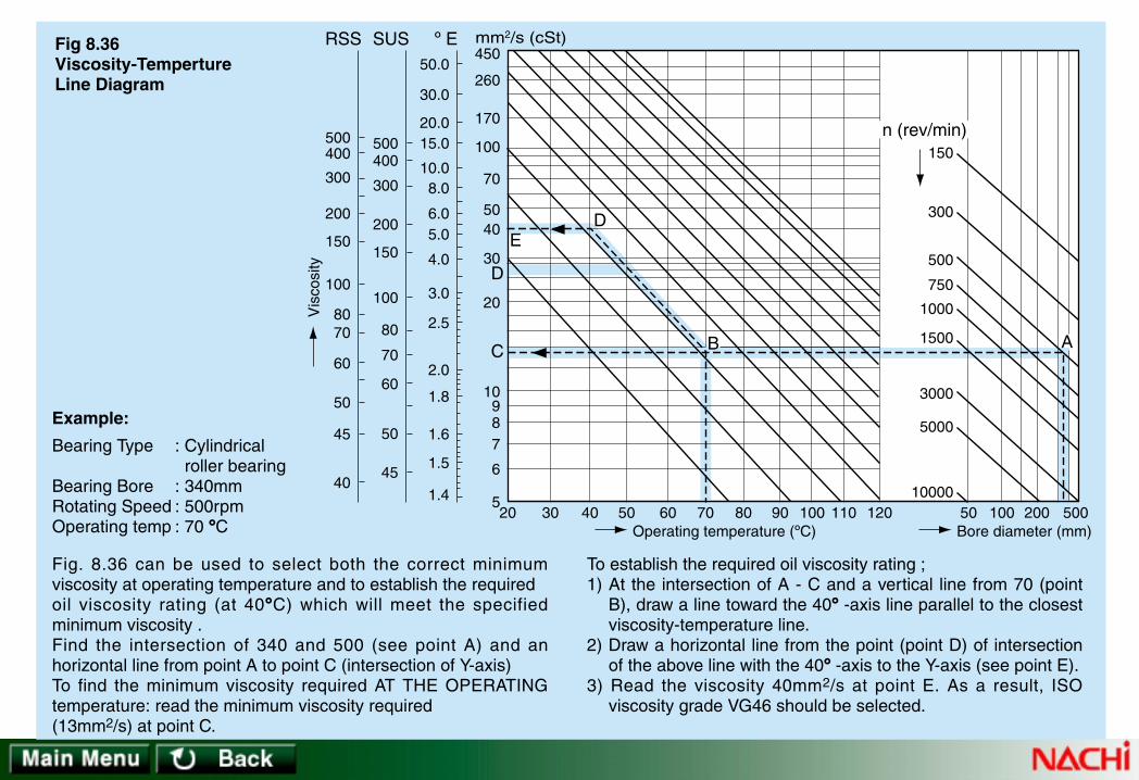
10000
5000
3000
1500
1000
750
500
300
150
30205
40
45
50
60
7080
100
150
200
300
400500
6
789
10
20
30
4050
70
100
170
260
450
40 50 60 70 80 90 100 110 120 50 100 200 500
ABC
D
mm2/s (cSt)º ESUSRSS
ED
Operating temperature (ºC)
Vis
cosi
ty
Bore diameter (mm)
50
60
70
80
100
150
200
300
400500
45
1.4
1.5
1.6
1.8
2.0
2.5
3.0
4.0
5.06.0
8.010.0
15.020.0
30.0
50.0
n (rev/min)
Fig 8.36 Viscosity-Temperture Line Diagram
Example:
Fig. 8.36 can be used to select both the correct minimumviscosity at operating temperature and to establish the requiredoil viscosity rating (at 40°C) which will meet the specifiedminimum viscosity .Find the intersection of 340 and 500 (see point A) and anhorizontal line from point A to point C (intersection of Y-axis)To find the minimum viscosity required AT THE OPERATINGtemperature: read the minimum viscosity required(13mm2/s) at point C.
To establish the required oil viscosity rating ;1) At the intersection of A - C and a vertical line from 70 (point
B), draw a line toward the 40° -axis line parallel to the closestviscosity-temperature line.
2) Draw a horizontal line from the point (point D) of intersectionof the above line with the 40° -axis to the Y-axis (see point E).
3) Read the viscosity 40mm2/s at point E. As a result, ISOviscosity grade VG46 should be selected.
Bearing Type : Cylindrical roller bearing
Bearing Bore : 340mmRotating Speed : 500rpmOperating temp : 70 °C

(2) Lubricating GreaseLubricating grease is composed of a base oil, a thickener, and additives.
• Base OilBase oil refers to the liquid lubricant carried by a thickener. Mineral oils are widely used as the base oils for grease. Synthetic oils suchas diester or silicone oil are also used for improving the heat resistance and stability of grease. In general, grease with a low-viscositybase oil is suitable for low temperatures and or low loads, while grease with a high viscosity base oil is suitable for high temperaturesand or high loads.Since lubricating performance is dependent on the thickener, additives, and viscosity, these components must be carefully selected tomeet operating conditions.
• ThickenerThe thickener has a sponge-like structure composed of a loosecombination of fine fibers or particles. Thickeners are roughly divided intometal soap, and non-soap types as shown below.Sodium (Na) soap grease may react with water to form an emulsion, andshould not be used for bearings operating in a high-moisture atmosphere.
• AdditivesAn additive is an agent that provides extreme pressure and rustresistance, anti-oxidation performance, and other properties to grease.Various additives are added to grease to provide specific properties to thegrease. Additives such as anti-oxidants, extreme pressure enhancers, andrust preventatives are often added to lubricating greases.Anti-oxidant additives protect grease from oxidation and deteriorationunder thermal influence over a long period. Extreme pressure additivesimprove load resistance and impact resistance. Rust preventive additivesprotect the bearing and other surrounding components against rusting.
Metal soap: Ca, Li, Na
Non-soapTHICKENER
Heat resistant organic base: Polyurea & Fluorides
Inorganic base: Silica gel and organic bentonite

0123456
355 ~ 385310 ~ 340265 ~ 295220 ~ 250175 ~ 205130 ~ 160 85 ~ 115
ASTM Workedpenetration
NLGINo.
Grease is numbereddifferently by the greasemanufacturers. Numbers250 and 300 of cup andfiber grease generallyuse penetration(at 25ºC), while mostversatile greases employNLGI penetrationnumbers such as 0, 1,and 2.
Table 8. 24 Grease Number and Penetration• PenetrationPenetration is a measure which indicates the solidity of grease. Ameasurment device has a cone with a specified weight and shape.The cone is penetrated into the sample grease for a specified time.Penetration is the depth to which the cone penetrates (in units of1/10 mm).
• Dropping PointDropping point is the temperature at which a grease sample dropsthrough a specified hole size after being heated and fluidized.

(3) Lubrication Amount
➀ OilWhen oil bath lubrication is being used and a bearing is mounted with its axis horizontal, oil should be added until the static oil level isat the center of the lowest bearing rolling element. For vertical shafts, add oil to cover 50% to 80% of the rolling element.
➁ GreaseThe rolling bearing and bearing housing should be filled until the grease occupies about 33 to 50 % of the respective volumes.Temperatures will tend to rise as speed increases (due to churning). Higher-speed operation will be more sensitive to excess greasefill, so it follows that at higher dmn values, the grease-fill quantity must be reduced.
a) Amount of Initial Grease FillThe amount of initial grease-fill required is calculated from the following equations:
Ball bearing:
Roller bearing:
b) Relubrication Amount Added at Service
Q d=2 5
900
.
Q d=2 5
350
.
Q D B= × ⋅0 005. • • • • • • (8.20)
• • • • • • (8.19)
• • • • • • (8.18)
where:Q =Amount of grease to add (g)(specific gravity of grease=0.9)D =Outside diameter of bearing (mm)B =Inner ring width (mm)
where:Q =Amount of filling grease (g)(specific gravity of grease=0.9)d =Bore diameter of bearing (mm)

• • • • • • (8.20)log L = (0.018f 0.025)T 2.77f + 6.3− − where:L =Grease life (h)f =(Operating speed) (rpm)/
(Bearing grease speed limit) (rpm)If f is less than 0.25, f is set = 0.25
T =Operating temperature (ºC)If T is less than 30ºC, T is set = 30.
➃ Grease Service LifeFor applications where relubrication is not possible or practical, grease service life may be estimated using Formula (8.21). The following formula was derived using a grease with Lithium thickener and mineral oil base.
➂ Lubrication IntervalFor a typical bearing, which operates at about 50ºC, lubricant should be replaced once a year. If operating temperature is 100ºC ormore, the lubricant should be replaced more than once every three months even if it has good heat stability.If oil bath lubricant becomes contaminated by water or foreign particles, it must be replaced immediately.The grease relubrication interval can be estimated from Fig 8.37.
Fig. 8.37 Grease lubrication interval
Table 8.25 Grease Properties

Fig. 8.37 Grease lubrication interval
Rotating speed n=100rpm
n=200
n=300
n=400
n=500 n=600
n=800 n=1000
n=1500
n=2000
n=3000
n=4000
n=6000
n=10000
20100500
750
1000
1500
2000
3000
4000
5000
6000
10000
20000
30000
40000
150
200
300
400
600
800
1000
1500
2000
3000
4000
6000
800010000
15000
20000
30000
40000
40 60 80 100 120 140 160 180 200 220 240 260 280
Bore diameter(mm)Spherical roller bearingsTapered roller bearingsThrust ball bearings
Lubrication interval(h)
Cylindricalroller bearings
Deep grooveball bearings
1000
1500
2000
3000
4000
6000
8000
10000
15000
20000
30000
40000

Containssmallamountof moisturefor structurestabilityNot suitablefor use athightemperature
Can not beused withwater ormoisturedue toemulsificationwith waterUsed atrelativelyhightemperature
Used invibratingconditiondue to goodtackiness
Generalpurposegreasewidely usedsmall ormediumsize ballbearings
Suitablefor lowtemperatureoperation
Wide workingtemperaturerangeMainly forlight loadconditions.
Used in largesize bearings
Suitable forhightemperatureand heavyloadconditions
Fair Good Fair Good Good Good
Good
–20 ~ +70
85 85 170 or Higher
Mineral Oil
Ca Soap
Poor
–10 ~ +120
160or Higher
200or Higher
200or Higher
150or Higher
Good
–10 ~ +80 –30 ~ +120
Good
–50 ~ +130 –50 ~ +170 –30 ~ +120
Good
–30 ~ +140
Wide workingtemperature rangeDepending oncombination ofthickener and base oilused, good hightemperature, lowtemperature or chemicalstability can be obtained
Good
Good
–10 ~ +130 –50 ~ +200
250 or Higher
CupGrease
Mineral Oil
Na Soap
FiberGrease
Mineral Oil
Al Soap
AluminumGrease
Mineral Oil
General-purposeGrease
Li Soap
DiesterGrease
SiliconeGrease
Mineral OilSilicone Oil
Mixed BaseGrease
Mineral Oil
ComplexGrease
Diester Oil
Ca + NaSoap, etc.
Li ComplexSoap, etc.
Mineral Oil Synthetic Oil
Bentonite, UreaFluoric, etc.
Non-Soap Base Grease
Mechanical Stability
Water Resistance
Working Temperature (ºC)
Dropping Point (ºC)
Remarks
Properties
Popular Name
Base Oil
Thickener
Table 8.25 Grease Properties
Poor forNa Soap
Note: 1. Greases with sodium (Na) soap thickener can not be used in applications there is a risk of water or high humidity because they became soft and flow out if they mix with water.2. In case of mixing different brands of grease (not recommendable), please consult grease manufacturer to determine if there are any detrimental effects.3. In case operating temperature are beyond what is shown in the table, please consult NACHI.

• In Fig. 8.38.1, Cr is the basic dynamic load rating and P is the equivalent dynamic load. If Cr/P is < 13, then the table speed limit ismultiplied by the correction factor from the curve shown in Fig. 8.38.1.
• In addition, if the ratio of the axial load (Fa) to the radial load (Fr) is larger than 0.3, that is, if Fa/Fr > 0.3, then the speed limit must beFURTHER multiplied by a correction factor as shown in Fig. 8.38.2
• Where the bearing is used at 75% or more of the speed limit, lubrication becomesa more sensitive operating consideration. If grease is to be used, then selection ofthe correct type and amount of grease is of paramount importance. If oil is used,then the correct selection of the feeding method and rate, and oil specification is ofextreme importance.
• Please contact NACHI for help in cases where application rotating speed exceedsthe corrected bearing speed limit.
• If the bearing is used in excess of the corrected speed limit, consideration must begiven to the accuracy and clearance of the bearing; and to the material and shapeof the retainer. Table 8.26 provides a guideline for maximum speed for bearingsusing special cages and internal design.
Deep groove ballAngular Contact ballCylindrical roller (single-row)Tapered rollerSpherical roller
2.522.521.5
Table 8.26 Correction of Allowable Speed Limitin High-speed Operation
Bearing typeCorrection
Factor
• Bearings exceeding a certain operating speed will begin to create internal heat which may not be controllable.• Speed limits vary with bearing types, dimensions, lubrication system, internal design of the bearing, and working loads. In addition,speed limits will vary according to the type of integral bearing seal which may be used (dependent on the speed of the seal contactarea).
• The term "speed limit" refers to the estimated speed, in revolutions per minute, at which bearings will remain serviceable.
The dimension tables show speed limits for both grease and oil lubrication. Please note that the published speed limits are based onoperation of properly lubricated, lightly-loaded bearings, installed on a horizontal shaft.
8.6.1 Speed Limit Cor8.6.1 Speed Limit Corrrection for Loadection for Load
8.6 Speed Limit8.6 Speed Limit
As noted above, bearing speed limits will vary with respect to load. Figs. 8.38.1 and 8.38.2 allow calculation of a speed limit correctionfactor which is applied to the speed limit tables.
Fig. 8.38.1 Correction Factor for Bearing LoadFig. 8.38.2 Correction Factor for Fa/Fr

4 5 6 7 8 9 10 11 12
0.6
0.7
0.8
0.9
1.0
0.6
0.50 0.5 1.0 1.5 2.0
0.7
0.8
0.9
1.0
CrP
: Dynamic load rating (N): Dynamic equivalent load (N)
FaFr
: Axial load (N): Radial load (N)
Cr/P
Fa/Fr
Sphericalroller bearing
Angular Contactball bearing
Single rowDeep grooveball bearing
Taperedroller bearing
Fig. 8.38.1 Correction Factor for Bearing Load Fig. 8.38.2 Correction Factor for Fa/FrC
orre
ctio
n fa
ctor
Cor
rect
ion
fact
or

8.7.1 Friction T8.7.1 Friction Tororqueque
Friction torque in rolling bearings will vary with the bearing load and the condition of the lubricant.Where the bearing load is light-to-normal (P≤0.12C) and the lubricant provides good separation between the rolling contact surfaces,bearing friction torque may be calculated using the following formula:
The coefficient of friction for variousbearing types is shown in Table 8.27.
8.7 Friction and T8.7 Friction and Temperaturemperature Risee Rise
where:M = friction torque (N · mm)µ = coefficient of frictionF = bearing load (N)d = shaft diameter (mm)
M F d= ⋅ ⋅µ2
• • • • • • (8.22)
Ball Bearings:
Roller Bearings:
Single row deep groove
Single row angular contact
Self-aligning
Thrust
Cylindrical
Spherical
Spherical thrust
Tapered
0.0010 ~ 0.0015
0.0012 ~ 0.0018
0.0008 ~ 0.0012
0.0010 ~ 0.0015
0.0008 ~ 0.0012
0.0020 ~ 0.0025
0.0020 ~ 0.0025
0.0018 ~ 0.0025
Radial load
Radial load
Radial load
Axial load
Radial load
Radial load
Axial load
Radial load
Bearing type Coefficient of friction ( ) Load condition
Table 8.27 Coefficient of Frictionµ

8.7.2 T8.7.2 Temperaturemperature Risee Rise
• Temperature rise in bearings is caused by the conversion of friction energy into heat.• Bearing temperature will generally rise quite abruptly during the initial stage of operation and then gradually climb until a steady
state is reached. The steady state condition will exist if temperature rise from frictional energy is removed by the cooling "heat-sink"effect from the shaft and housing, and from heat conductance via the shaft, housing and lubricant.
• The time until equilibrium is attained depends on the difference between heating volume generated by the bearing and the heatingvolume removed by the cooling effect.
• If the equilibrium temperature is excessively high, then review of the bearing application should be done. The bearing internalclearance or preload, fits, bearing support structure, seal contact area surface finish, rotating speed, load, and lubrication type,amount, and delivery system are subjects for investigation where excessive temperature occurs.
• An abnormal temperature rise can cause a spiraling condition where no equilibrium will occur, thus leading to a break-down in thelubricant and lubricant film, with catastrophic results.

8.8.1 Storage and Handling8.8.1 Storage and Handling
The major problems encountered during the bearing storage and retrieval operations are in rusting and impact damage to the parts.• To protect bearings against rusting during storage, parts should be placed in a dry, clean, cool area. Bearings should not be
subjected to extremes of humidity during storage.• Impacts to bearings can create damage to the raceways, rolling elements, and cages. Do not drop bearings. Bearings which are
dropped should not be used for service.
8.8 Mounting and Dismounting8.8 Mounting and Dismounting
Rolling bearings have higher accuracy than other parts in most equipment and are often considered to be the most important rotatingcomponent. Improper handling of bearings reduces machine accuracy and can cause early bearing failures. To attain predictedbearing performance, utmost care should be taken in handling bearings from the point-of-receipt through the mounting operation.
8.8.2 Mounting8.8.2 Mounting
Proper bearing mounting governs the life, accuracy, and performance of a bearing. Before mounting the bearing, carefully check thefollowing points.Check to see if:• the job standards are established and the necessary jigs are prepared.• the shaft and housing size, tolerance, and finish are defined and met.• lubricant type and amount specified is at hand.• inspection standards are established.• the method of cleaning the bearing and relevant parts is clear.
(1) Mounting Precautions• Select a clean, dry place to handle the bearing, and keep necessary tools and workbench clean.• Do not unpack the bearing until it is to be mounted.• If the bearing is unpacked before mounting for acceptance inspection or for any other reason, follow these directions:
a) If the bearing is to be mounted within a short time period, coat it with rust preventive oil and place it in a clean container.b) If the bearing will not be mounted in a short time, coat it with rust preventative oil and repack it in the original container.

• Check to see that the lubricant drums, cans, tubes, or applicators are clean and or closed. Checkto be sure that the bearing housing is clean and free from flaws, impressions, burrs, or any otherdefects.
• For grease lubrication, you may fill the new bearing with grease without cleaning the bearing. Ifthe bearing is small or is used for high-speed operation, whether it is lubricated with oil or grease,wash the bearing with clean kerosene or warm, light oil to remove the rust preventative. Howeverbearings with seals or shields must not be washed and heated.If gear oil is used for lubrication, clean the bearing to remove any rust preventive oil.
Surface finishFig. 8.39
Corner radius of shaft (Good)Fig. 8.40
Corner radius of shaft (Poor)Fig. 8.41
(2) Shaft• Before mounting the bearing on the shaft, check to see that the shaft is finished to the specifiedsize and accuracy.
• Check the shaft for surface finish. If the shaft fit surface has a poor surface finish (see Fig. 8.39),the surface may be smoothed during mounting, possibly resulting in bearing ring creep, shaftwear, and early bearing failure.
• Be sure that the shaft shoulders are finished at a right angle to the shaft axis, otherwise thebearing will be misaligned resulting in early bearing failure.
• Finish the corner radius of the shaft to the specified dimensions. Make sure the corner radius ofthe shaft is slightly smaller than that of the bearing as shown in Fig. 8.40. Never have the cornerradius of the shaft larger than that of the bearing (see Fig. 8.41), otherwise, the bearing ring maybe misaligned and early bearing failure will occur.
• Out-of-roundness of shaftMake sure that the shaft is accurate to out-of-roundness and cylindricity specifications. The innerring of the bearing is an elastic body, having a relatively thin wall, so if the inner ring is fitted to ashaft having poor roundness, the inner ring raceway will be deformed accordingly.
• Contact surface of oil sealsWhen using an oil seal, finish the seal contact surface to Ra < 0.8 µm. If the finish is rougher thanRa < 0.8 µm, the seal will gradually wear until it has no sealing effect. Also make sure that thecontact surface is within the runout tolerance, otherwise oil leaks may occur since the seal lip maynot stay in contact with the rotating shaft.

(3) Bearing Housing• Purposes of the bearing housing are:
a) to maintain the bearing position for load support.b) to protect the bearing from the intrusion of foreign material.c) to provide a structure that will keep the bearing well lubricated.
• Verify that the housing bore diameter is to design specifications. If a loose fit class of H or looser is specified, check to make certainthat the bearing will move freely in the bearing housing during installation. On horizontally-split bearing housings such as used onpillow blocks, do not mix the caps and bases during a reassembly procedure since these parts are mated during manufacture. In thelatter case, mixing may cause either pinching or looseness of the bearing.
• Allowance must be made for linear expansion of the shaft due to temperature rise. When two or more bearings are mounted on asingle shaft, comply with the following directions:Fix one bearing in the axial direction in the housing, and make sure that the other bearing(s) are free to move in an axial direction.
(4) Accessory Mounting PartsPrior to bearing mounting, gather a set of the parts required for the mounting job. These accessory parts may include washers,adapters, withdrawal sleeves, spacer rings, slingers, oil seals, O-rings, shaft nuts, and snap rings for the shaft and or housing bore.Thoroughly clean these accessory parts and check them for appearance and size.
Other Precautions• Be sure that the side of the shaft nut is at a right angle to the thread, otherwise, when tightened, the side of the shaft nut will makeuneven contact with the side of the bearing causing early bearing failure. Use particular care when the bearing is used for high-accuracy applications such as lathes.
• Check the washer and spacer ring for parallelism of both sides.• The oil seal and O-ring may create a temperature rise because the contact force is too great or because they are initially dry. Applyoil or grease to the contact surfaces to help prevent premature wear and reduce torque.

8.8.3 Bearing Mounting Considerations8.8.3 Bearing Mounting Considerations
When pressing a bearing into position, press against the ring with interference fit. Pressing through the rolling elements will causedamage, such as brinell marks or cracks to the elements and rings and the bearing will be unusable.For inner ring rotating loads, the bearing is generally interference-fit to the shaft and either expansion fitting or press fitting can beused. expansion fitting may be the more appropriate method for mounting larger bore bearings.A tapered-bore bearing can be mounted directly to a tapered shaft or with an adapter or withdrawal sleeve. When a withdrawal sleeveis used for larger bore bearings, the hydraulic mounting procedure will facilitate the process. Note that the use of hydraulic mounting ofbearings to tapered journals is also very useful for larger bearing sizes.For an outer ring rotating load, the bearing is usually interference-fitted with the housing. Either press fitting or shrink fitting may beused. In the case of the latter process, the bearing or bearing outer ring may be cooled to attain the fit.
(1) Mounting Cylindrical-bore Bearings• Press fittingMany cylindrical-bore bearing applications use press fitting with the shaft. Use a jig which matches the inner ring as shown in Fig.8.42. Press fit the inner ring using a press or jack.To press fit the inner and outer rings simultaneously, use a jig as shown in Fig. 8.43.Apply high-viscosity oil to the shaft and the contact faces of the bearing before press fitting.
Fig. 8.42 Press Fitting of Inner Ring Fig. 8.43 Simultaneous Press Fitting of Inner Ring
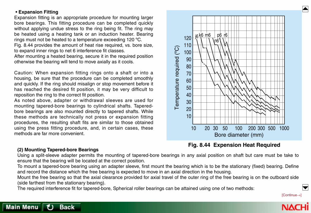
• Expansion FittingExpansion fitting is an appropriate procedure for mounting largerbore bearings. This fitting procedure can be completed quicklywithout applying undue stress to the ring being fit. The ring maybe heated using a heating tank or an induction heater. Bearingrings must not be heated to a temperature exceeding 120 ºC.Fig. 8.44 provides the amount of heat rise required, vs. bore size,to expand inner rings to net 6 interference fit classes.After mounting a heated bearing, secure it in the required positionotherwise the bearing will tend to move axially as it cools.
Caution: When expansion fitting rings onto a shaft or into ahousing, be sure that the procedure can be completed smoothlyand quickly. If the ring should misalign or stop movement before ithas reached the desired fit position, it may be very difficult toreposition the ring to the correct fit position.As noted above, adapter or withdrawal sleeves are used formounting tapered-bore bearings to cylindrical shafts. Tapered-bore bearings are also mounted directly to tapered shafts. Whilethese methods are technically not press or expansion fittingprocedures, the resulting shaft fits are similar to those obtainedusing the press fitting procedure, and, in certain cases, thesemethods are far more convenient.
Fig. 8.44 Expension Heat Required
120110100
908070605040302010
10 20 30 50 100Bore diameter (mm)
Tem
pera
ture
req
uire
d (º
C)
200 300 500 1000
j6 k6 m6 p6 r6n6
(2) Mounting Tapered-bore BearingsUsing a split-sleeve adapter permits the mounting of tapered-bore bearings in any axial position on shaft but care must be take toensure that the bearing will be located at the correct position.To mount a tapered-bore bearing using an adapter sleeve, first mount the bearing which is to be the stationary (fixed) bearing. Defineand record the distance which the free bearing is expected to move in an axial direction in the housing.Mount the free bearing so that the axial clearance provided for axial travel of the outer ring of the free bearing is on the outboard side(side farthest from the stationary bearing).The required interference fit for tapered-bore, Spherical roller bearings can be attained using one of two methods:
[Continue→]

a) by driving the bearing onto the sleeve by a predetermined distance; or,b) by measurement of residual bearing internal clearance as the sleeve is pushed into the bearing inner ring (see Table 8.28).
Since exact measurement of the axial drive-up distance is extremely difficult, the residual method is usually the method of choice.
The residual method involves measuring the bearing unmounted internal clearance and then pulling upthe adapter sleeve until the measured clearance (the residual) = the unmounted (original) clearance -the reduction amount required to attain the correct interference fit (see Table 8.28 for the reductionamount). Clearance measurements are made using a thickness (feeler) gauge. (Note that the thicknessgauge should be inserted over two or three unloaded rollers on each row of rollers and that the bearingbore must be in a horizontal position with respect to the shaft axis, with the outer ring centered over therolling elements).Table 8.28 shows axial movement and radial clearance reduction for the mounting of Spherical rollerbearings.Heating of larger tapered-bore bearings may be used in conjunction with measurement of traveldistance but be sure to check the results using the residual method (taking the unmounted clearancemeasurements and the final, residual clearance, when the bearing is cool). Also be sure that thebearing is not heated to over 120 ºC.When using a withdrawal sleeve for large-bore bearings, use of a hydraulic assist procedure isrecommended. See Fig. 8.45 which shows use of a hydraulic nut.
Fig. 8.45 Hydraulic Nut
(3) Other Mounting Precautions• For paired Tapered roller bearings, be sure to adjust the axial clearance to the specified value using shims where necessary.• For bearing types with separable inner and outer members such as Cylindrical or Tapered roller bearings, mount the inner and outerring separately and carefully assemble the shaft into the housing while making sure that no damage occurs to the inner or outerrings or rolling elements.
[→Continue]
Table 8.28 Tapered-bore Spherical Roller Bearings: Axial Movement and Radial Clearance Reduction

304050
6580
100
120140160
180200225
250280315
355400450
405065
80100120
140160180
200225250
280315355
400450500
0.350.40.45
0.60.70.75
1.11.21.3
1.41.61.7
1.92.02.4
2.63.13.3
min maxIncl.Over
Nominal borediameter d (mm)
Table 8.28 Tapered-bore Spherical Roller Bearings: Axial Movement and Radial Clearance Reduction
Axial movement (mm)
min max
Taper: 1/12 Taper: 1/30
maxmin
Radial clearancereduction (mm)
0.0250.0300.040
0.0500.0600.070
0.0900.1000.110
0.1200.1400.150
0.1700.1900.210
0.2300.2600.280
0.0200.0250.030
0.0400.0450.050
0.0650.0750.080
0.0900.1000.110
0.1200.1300.150
0.1700.2000.210
0.40.450.6
0.750.91.1
1.41.61.7
1.92.22.4
2.73.03.3
3.64.04.4
– – –
– 2.252.75
3.54.04.25
5.05.56.0
6.757.58.25
9.0 10.0 11.0
– – –
– 1.751.9
2.753.03.25
3.54.04.25
4.755.06.0
6.57.758.25

8.8.4 Mounting and Dismounting For8.8.4 Mounting and Dismounting Forcece
An approximate force necessary to install or remove an inner ring from a shaft may be calculated using the following equation.
Ka fk fe de= ⋅ ⋅ ∆ • • • • • • (8.23) where:Ka = press fit or dismount force (KN)∆de = effective interference (mm)fk = factor from Table 8.29fe = from following equation
fe B ddi
= ⋅ − ( )
12 where:
B = inner ring width (mm)d = inner ring bore diameter (mm)di = mean inner ring outside diameter (mm)di =̇. 0.25 (D+3d)···for Cylindrical roller bearings and Self-aligning Ball bearing series 22 and 23di =̇. 0.1 (3D+7d)···for other bearings
where:D = Bearing outside diameter
Inner ring pressed to cylindrical shaft*
Inner ring pulled from cylindrical shaftInner ring press fit to tapered shaft or sleeve*
Inner ring pulled from tapered shaftTapered sleeve press fit between shaft & bearing*
Tapered sleeve pulled from between shaft & bearing
39 59 54 44 98108
fkCondition
* Shaft and bearing bore thinly coated with oil.
Table. 8.29 Value fk (Average)
Fig. 8.46 ~ 8.49 show dismount and press fit force by diameter series.

500
400
300
200
100
20 60 100Bearing width (mm)
Dis
mou
nt fo
rce
(kN
)
Dis
mou
nt fo
rce
(kN
)
Pre
ss fi
t for
ce (
kN)
Pre
ss fi
t for
ce (
kN)
Diameter series 2, 3
140 180In
terfe
renc
e 90
m
0
500
80
70
60
50
40
30
20
10
8070605040
302010
8070605040302010
8070
605040302010
400
300
200
100
20 60 100Bearing width (mm)
Diameter series 9, 0
140 1800
500
400
300
200
100
20 60 100Bearing width (mm)
Diameter series 2, 3
140 1800
500
400
300
200
100
20 60 100Bearing width (mm)
Diameter series 9, 0
140 1800
Fig. 8.46 Dismount Force Fig. 8.47 Dismount Force
Fig. 8.48 Press-fit Force Fig. 8.49 Press-fit Force
Inter
feren
ce 9
0 m
Interference
90
m
Interference 90 mµ
µ
µ
µ

8.8.5 Operation Inspection8.8.5 Operation Inspection
Verify satisfactory service with a test run. General precautions for a test run are:
• Make sure that all drive covers are in place, all bolts and nuts are tight, and appropriate clearance is provided between the shaft andall stationary parts.
• If possible, manually turn the shaft to see if there is rubbing or abnormal noise.• If the machine is large and the shaft cannot be turned by hand, start the machine at as low speed as possible and check for rubbingor abnormal noise while coasting the machine.
• If no trouble is found during the above checks, run the machine at the design speed until attaining a steady-state temperature.• Recheck bolt and nut tightness. Check for oil leaks, and abnormal noise. If possible, extract a sample of the oil and check it forforeign matter.
• Begin regular operation.
If trouble is encountered during machine operation, refer to Section 9, "Trouble-shooting Bearing Problems".
8.8.6 Dismounting8.8.6 Dismounting
Bearings may be dismounted for periodic machine inspection, or when machine break down has occurred. The condition of all rotatingparts and interfaces should be checked and recorded to collect data for operating improvements. The recording of data is essentialwhere a parts failure has occurred to enable a solution to any existing trouble.In dismounting the bearing, check to see:
• If the bearing is satisfactorily mounted. (Bolts, and nuts tightened, interference of slinger with bearing housing, etc.)• If there is (was) an adequate lube supply. Check for lubricant contamination and sample for residues.• That the inner and outer ring have retained the fits as mounted.• If the bearing clearance is as specified. If possible, measure the clearance of the mounted bearing.• The condition of the bearing.
[Continue→]

Fig. 8.50 Dismounting BearingUsing Press
Fig. 8.53 Dismounting Bearingwith Special Puller
Spanner wrench
Fig. 8.51 Dismounting Bearingwith Spanner Wrench
3-jaw puller 2-jaw puller
Fig. 8.52
Fig. 8.54 Puller Attachment
Inner ring
Inner Ring Removalwith Induction Heater
Fig. 8.55 Fig. 8.56 Oil Injector
To dismount a Cylindrical roller bearing,the inner ring may be locally heated withan induction heater to facilitate removalfrom the shaft. (See Fig. 8.55.)For large-bore bearings, which are oftendifficult to dismount, a hydraulic nut or oilinjector system is recommended. SeeFig. 8.45 and Fig. 8.56 respectively.
[→Continue]
Before starting to dismount a bearing, review the following points:
• Dismount method• Fit conditions• Jigs required for dismounting
- Press (Fig. 8.50)- Spanner wrench (Fig. 8.51)- Puller (Fig. 8.52)- Special puller (Fig. 8.53)- Holder (Fig. 8.54)

Rolling contact bearings must be carefully handled, mounted, and maintained in order to operate satisfactorily.The cause of unsatisfactory operation must be determined to prevent recurrence. There are three categories of data which should begathered to enable the correct diagnosis of bearing problems:• Time of occurrence.• Symptoms during operation.• Condition of bearing.Although the origin of bearing problems can sometimes be determined using data from only one of the data categories, quick andaccurate analysis requires as much data as possible.See Tables 9.1, 9.2 and 9.3.
Soon after periodicdisassembly
Soon after installation
After replacement or repairof other drive parts
Soon after re-lubrication
During normal operation
Bearingselection
Lubricant type,system or amount
Design ormanufacture ofother drive parts
Seal failureDefective bearing BearinginstallationTime of
Occurrence
Cause
Table 9.1 Time of Occurrence
9. T9. Trrouble-shooting Bearing Prouble-shooting Bearing Problemsoblems

Low level metallic sound
High level metallic sound
Irregular sound
Ever-changing sound
Abnormal temperature rise
Reduction in accuracy
Unstable operation
Contaminated lubricant
Loss of clearance, creep, insufficient or excesslubricant, excess load
Change of clearance by temperature riseDefect in progress on raceway
Excess clearance, contaminants, defect of rollingelement surface, improper lube
Loss of clearance, poor lubrication
Impressions on raceway
Raceway or rolling element broken by impurities,or insufficient lubricant
Broken raceway, rolling elementForeign matterExcess clearance
Poor lubrication, foreign matter, wear
Check with audiophone, vibration pickup, etc.
Use a surface thermometer.
Operation condition Cause Remarks
Table 9.2 Symptom During Operation
Noise
Example:
Example: vibration
Lathe: stick-slip marks Grinder: wavy pattern Cold roll mill: occulting wave pattern
(1) Premature Flaking(2) Seizure(3) Breakage
(4) Brinelling(5) Fretting(6) Smearing
(7) Excessive Wear(8) Rusting, Corrosion(9) Creep
Table 9.3

The repeated heavy stress cycle between the bearing raceway and rolling elementsurface results in fatigue cracks which become loosened from bearing materials.
(1) Pr(1) Prematuremature Flakinge Flaking
• Abnormal axial load or excessive loadcaused by expanded shaft.
• Deflection or misalignment of shaft.• Poor parallelism of inner and outer rings.• Poor lublication• Rusting, Nicks, Galling from dirt, etc.
• Abnormal axial load or excessive loadcaused by expanded shaft.
• Deflection or misalignment of shaft.• Poor parallelism of inner and outer rings.• Poor lublication• Rusting, Nicks, Galling from dirt, etc.
■ Causes ■ Countermeasures
Bearing is seized up by excessive heat. Discoloration, softening and fusion ofraceway and rolling element.
(2) Seizur(2) Seizuree
• Loss of clearance• Operating over limiting speed• Poor or improper lubricant.
• Review fitting and bearing clearance.• Review type of bearing.• Select a proper lubricant, and feed it in
proper quantity.
■ Causes ■ Countermeasures

Splits and cracks in the inner/outer ring or rolling element.
(3) Br(3) Breakageeakage
• Excessive interference fit.• Bearing seat has larger corner radius
than bearing.• Excess clearance during operation.• Excess impact load.
• Check fits. Finish shaft and sleeve tohigher accuracy.
• Make shaft corner radius smaller thanthat of the bearing.
• Check fits and bearing clearance.• Re-check load conditions.
■ Causes ■ Countermeasures
Brinelling, indentation and pear skin of bearing raceway and rolling element.
(4) Brinelling(4) Brinelling
• Impact applied during mounting.• Impact from dropped bearing• Contamination• Load applied to bearing at rest in excess
of static load rating.
• Carefully handle the bearing.• Clean shaft and housing• Improve the sealing• Re-check load conditions.
■ Causes ■ Countermeasures

Occurred when a small relative motion is repeatedly caused in non rotatingbearing. Fretting surface wear producing red colored particles at fitting surface.
(5) Fr(5) Frettingetting
• Vibration applied to bearing at rest (e. g.during shipment)
• swing with smaller amplitude.• Minute clearance on fit surface.• Slight sliding during operation as a result
reduced interference under a load.
• Fix the shaft and housing dur ingshipment.
• Apply a preload. Use oil for lubrication.• Increase the interference.• Apply oil
■ Causes ■ Countermeasures
Metal to metal contact due to the destruction of oil film.Sliding motion between outer/inner ring and rolling element.
(6) Smearing(6) Smearing
• Excess axial load. Misalignment ofbearing.
• Poor lubrication.• Intrusion and galling of foreign matter.• High acceleration on start-up.
• Correct mounting errors.• Review the load condition.• Select a proper lubricant, and feed it in
proper quantity.• Improve the sealing.• Clean shaft and housing.• Avoid sharp acceleration.
■ Causes ■ Countermeasures

Abnormal wear of flange face, rolling element and retainer.
(7) Excessive W(7) Excessive Wearear
• Foreign matter and corrosion acting aslapping agent
• Insufficient or incorrect lubricant.
• Improve sealing• Clean shaft and housing• Check lubricant for type and amount.
■ Causes ■ Countermeasures
Rusting and corrosion of bearing ring and rolling element surface.
(8) Rusting, Cor(8) Rusting, Corrrosionosion
• Improper storage, cleaning.• Improper washing oil.• Poor rust prevention• Corrosive gas, liquid or water.• Handling with unprotected hand.• Chemical action of lubricant.
• Improve storage and handling.• Re-check washing oil• Review rust prevention.• Improve sealing• Correct handling.• Check lubricant.
■ Causes ■ Countermeasures

Galling, wear, sliding and discoloration of fit face.
(9) Cr(9) Creepeep
• Insufficient interference.• Insufficient tightened sleeve.• Insufficient surface pressure due to low
rigidity and inaccurate shaft and housing.
• Check fits.• Tighten sleevel• Redesign for greater rigidity.
■ Causes ■ Countermeasures

0.6 2.510
183050
80120150
180250315
400500630
800100012501600
2.51018
305080
120150180
250315400
500630800
1000125016002000
Over Incl.
Bearing borediameter Nominal
d(mm)
( 1 ) 000
000
000
000
000
0000
– 8– 8– 8
– 10– 12– 15
– 20– 25– 25
– 30– 35– 40
– 45– 50– 75
– 100– 125– 160– 200
000
000
000
000
00–
––––
– 7– 7– 7
– 8– 10– 12
– 15– 18– 18
– 22– 25– 30
– 35– 40
–
––––
000
000
000
000
–––
––––
– 5– 5– 5
– 6– 8– 9
– 10– 13– 13
– 15– 18– 23
–––
––––
000
000
000
0––
–––
––––
– 4– 4– 4
– 5– 6– 7
– 8– 10– 10
– 12––
–––
––––
000
000
000
0––
–––
––––
– 2.5– 2.5– 2.5
– 2.5– 2.5– 4
– 5 – 7 – 7
– 8 ––
–––
––––
000
000
000
0––
–––
––––
– 4– 4– 4
– 5– 6– 7
– 8– 10– 10
– 12––
–––
––––
000
000
000
0––
–––
––––
– 2.5– 2.5– 2.5
– 2.5– 2.5– 4
– 5 – 7 – 7
– 8 ––
–––
––––
High Low High Low High Low High Low High Low High Low High Low0,1,2,3,4
Diameter seriesClass 4
Class 0 Class 6 Class 5 Class 4 Class 2 Class 2
Single plane mean bore diameter deviation Deviation of a single bore diameter (2)Bearing with cylindrical bore
mpd sd
Notes:
Remarks: The high deviation of bearing cylindrical bore diameter specified in this table does not apply within a distance of 1.2 × r (max) from the ring face.
(1) This diameter is included in this group.(2) Applies to bearings with cylindrical bore.(3) Width deviation and variation of outer ring are the same with of inner ring. Outer ring width variation of classes 5, 4 and 2 are listed in Table 5.1.2.(4) Applies to the rings of single bearings made for paired of stack mounting.(5) Applies ro radial ball bearings such as deep groove ball bearing, angular contact ball bearings.
Unit: mµTable 5.1.1 Tolerance Values of Inner Ring and of Outer Ring Width (1/4)

0.6 2.510
183050
80120150
180250315
400500630
800100012501600
2.51018
305080
120150180
250315400
500630800
1000125016002000
Over Incl.
Bearing borediameter Nominal
d(mm)
( 1 ) 101010
131519
253131
384450
5663–
––––
8 8 8
101219
253131
384450
5663–
––––
6 6 6
8 911
151919
232630
3438–
––––
9 9 9
101315
192323
283138
4450–
––––
7 7 7
81015
192323
283138
4450–
––––
5 5 5
6 8 9
111414
171923
2630–
––––
5 5 5
6 8 9
101313
151823
–––
––––
4 4 4
5 6 7
81010
121418
–––
––––
4 4 4
5 6 7
81010
12––
–––
––––
333
455
688
9––
–––
––––
2.52.52.5
2.52.54
5 7 7
8 ––
–––
––––
6 6 6
8 911
151919
232630
3438–
––––
5 5 5
6 8 9
111414
171923
2630–
––––
3 3 3
3 4 5
5 7 7
8 912
–––
––––
2 2 2
2.53 3.5
4 5 5
6 ––
–––
––––
1.51.51.5
1.51.52
2.53.53.5
4 ––
–––
––––
7,8,9 0,1 2,3,4 7,8,9 0,1 2,3,4 7,8,9 0,1,2,3,4 7,8,9 0,1,2,3,4Class 2 Class 0 Class 6 Class 5 Class 4 Class 2Diameter series
Class 0Diameter series
Class 6Diameter series
Class 5Diameter series
Class 4
Bore diameter variation in a single radial plane (2)Vd p
Main bore diameter variation (2)Vd mp
Bearing with cylindrical bore
Max Max Max Max Max Max Max Max Max Max
Unit: mµ
Notes:
Remarks: The high deviation of bearing cylindrical bore diameter specified in this table does not apply within a distance of 1.2 × r (max) from the ring face.
(1) This diameter is included in this group.(2) Applies to bearings with cylindrical bore.(3) Width deviation and variation of outer ring are the same with of inner ring. Outer ring width variation of classes 5, 4 and 2 are listed in Table 5.1.2.(4) Applies to the rings of single bearings made for paired of stack mounting.(5) Applies ro radial ball bearings such as deep groove ball bearing, angular contact ball bearings.
Table 5.1.1 Tolerance Values of Inner Ring and of Outer Ring Width (2/4)

0.6 2.510
183050
80120150
180250315
400500630
800100012501600
2.51018
305080
120150180
250315400
500630800
1000125016002000
( 1 )
Over Incl.
Bearing borediameter Nominal
d(mm)
000
000
000
000
000
0000
– 40– 120– 120
– 120– 120– 150
– 200– 250– 250
– 300– 350– 400
– 450– 500– 750
– 1000– 1250– 1600– 2000
000
000
000
000
–––
––––
– 40– 40– 80
– 120– 120– 150
– 200– 250– 250
– 300– 350– 400
–––
––––
000
000
000
0––
–––
––––
– 40– 40– 80
– 120– 120– 150
– 200– 250– 250
– 300––
–––
––––
–00
000
000
000
–––
––––
–– 250– 250
– 250– 250– 380
– 380– 500– 500
– 500– 500– 630
–––
––––
121520
202025
253030
303540
506070
80100 120 140
121520
202025
253030
303540
4550–
––––
555
556
788
101315
–––
––––
2.52.52.5
2.534
455
6––
–––
––––
High Low High Low High Low High Low High Low
Class 0Class 6
Class 5Class 4 Class 2
Class 0Class 6
Deviation of a single inner ring width (or a single outer ring width) (2) Inner (or outer) ring width variation
1.51.51.5
1.51.51.5
2.52.54
5––
–––
––––
000
000
000
000
–––
––––
– 250– 250– 250
– 250– 250– 250
– 380– 380– 380
– 500– 500– 630
–––
––––
MaxMaxMaxMaxMaxClass 0 Class 6 Class 5 Class 4 Class 2
Class 5Class 4
Single bearing Inner ring (or outer ring) (3) Inner ring
VBS (or VCS )Paired or stack mounted bearing (4)
sB sC
Unit: mµ
Notes:
Remarks: The high deviation of bearing cylindrical bore diameter specified in this table does not apply within a distance of 1.2 × r (max) from the ring face.
(1) This diameter is included in this group.(2) Applies to bearings with cylindrical bore.(3) Width deviation and variation of outer ring are the same with of inner ring. Outer ring width variation of classes 5, 4 and 2 are listed in Table 5.1.2.(4) Applies to the rings of single bearings made for paired of stack mounting.(5) Applies ro radial ball bearings such as deep groove ball bearing, angular contact ball bearings.
(or )
Table 5.1.1 Tolerance Values of Inner Ring and of Outer Ring Width (3/4)

0.6 2.510
183050
80120150
180250315
400500630
800100012501600
2.51018
305080
120150180
250315400
500630800
1000125016002000
( 1 )
Over Incl.
Bearing borediameter Nominal
d(mm)
333
445
577
8––
–––
––––
Class 4 Class 2
Max Max
Class 5
Max
333
445
566
7––
–––
––––
Class 4 Class 2
Max Max
777
888
91010
111315
–––
––––
Class 5
Max
Class 2
2.52.52.5
344
566
8 – –
– – –
– – – –
Class 4
444
455
688
101315
–––
––––
Class 5
Max
5 6 7
81010
131818
202530
3540–
––––
Class 6
Max
101010
131520
253030
405060
657080
90100120140
Class 0
Max
Radial runout of assembled bearing inner ring
MaxMax
1.51.51.5
2.52.52.5
2.52.55
5 – –
– – –
– – – –
1.51.51.5
1.51.51.5
2.52.54
5 – –
– – –
– – – –
777
888
91010
131520
–––
––––
1.51.51.5
2.52.52.5
2.52.55
5 – –
– – –
– – – –
Kia
Inner ring reference facerunout with bore
Assembled bearing inner ringface runout with raceway Sia (5)Sd
Unit: mµ
Notes:
Remarks: The high deviation of bearing cylindrical bore diameter specified in this table does not apply within a distance of 1.2 × r (max) from the ring face.
(1) This diameter is included in this group.(2) Applies to bearings with cylindrical bore.(3) Width deviation and variation of outer ring are the same with of inner ring. Outer ring width variation of classes 5, 4 and 2 are listed in Table 5.1.2.(4) Applies to the rings of single bearings made for paired of stack mounting.(5) Applies ro radial ball bearings such as deep groove ball bearing, angular contact ball bearings.
Table 5.1.1 Tolerance Values of Inner Ring and of Outer Ring Width (4/4)

2.56
18
305080
120150180
250315400
500630800
1000125016002000
61830
5080
120
150180250
315400500
630800
1000
1250160020002500
( 1 )
Over Incl.
Bearing outsidediameter Nominal
D(mm)
000
000
000
000
000
0000
– 8– 8– 9
– 11– 13– 15
– 18– 25– 30
– 35– 40– 45
– 50– 75– 100
– 125– 160– 200– 250
000
000
000
000
000
––––
– 7– 7– 8
– 9– 11– 13
– 15– 18– 20
– 25– 28– 33
– 38– 45– 60
––––
000
000
000
000
00–
––––
– 5– 5– 6
– 7– 9– 10
– 11– 13– 15
– 18– 20– 23
– 28– 35
–
––––
000
000
000
00–
–––
––––
– 4– 4– 5
– 6– 7– 8
– 9– 10– 11
– 13– 15
–
–––
––––
000
000
000
00–
–––
––––
– 2.5– 2.5– 4
– 4 – 4 – 5
– 5 – 7 – 8
– 8 – 10
–
–––
––––
000
000
000
00–
–––
––––
– 4– 4– 5
– 6– 7– 8
– 9– 10– 11
– 13– 15
–
–––
––––
000
000
000
00–
–––
––––
– 2.5– 2.5– 4
– 4 – 4 – 5
– 5 – 7 – 8
– 8 – 10
–
–––
––––
High Low High Low High Low High Low High Low High Low High Low0,1,2,3,4
Diameter series
Class 4
Class 0 Class 6 Class 5 Class 4 Class 2Class 2
Single plane mean outside diameter deviation Deviation of a single outside diameterBearing outside diameter
mpD sD
Unit: m
Notes:
Remarks: The high deviation of bearing cylindrical bore diameter specified in this table does not apply within a distance of 1.2 × r (max) from the ring face.
(1) This diameter is included in this group.(2) Applies before mounting and after removal of internal or external snap ring.(3) Applies to radial ball bearings such as deep groove ball bearings, angular contact ball bearings.(4) Outer ring width variation of class 0 and 6 are listed in Table 5.1.1.(5) Applies to radial ball bearings such as deep groove ball bearing, angular contact ball bearings.
µTable 5.1.2 Tolerance Values of Outer Ring (1/4)

2.56
18
305080
120150180
250315400
500630800
1000125016002000
61830
5080
120
150180250
315400500
630800
1000
1250160020002500
( 1 )
Over Incl.
Bearing outsidediameter Nominal
D(mm)
334
556
788
1011
–
–––
––––
2.52.54
445
578
810–
–––
––––
Outside diameter variation in a single radial plane (2)VDp
445
678
91011
1315
–
–––
––––
445
578
81011
141517
2126
–
––––
556
79
10
111315
182023
2835
–
––––
99
10
131620
2530
–
–––
–––
––––
556
78
10
111415
192125
293445
––––
778
91116
192325
313541
485675
––––
99
10
111416
192325
313541
485675
––––
101012
162026
3038
–
–––
–––
––––
667
81011
141923
263034
385575
––––
889
111319
233138
445056
6394
125
– – – –
101012
141619
233138
445056
6394
125
– – – –
MaxMaxMax7,8,9 0,1,2,3,4
Diameter seriesOpen bearing
Class 4
Max7,8,9 0,1,2,3,4
Diameter seriesOpen bearing
Class 5
MaxMax2,3,4 0,1,2,3,4
Max0,1
Max7,8,9
Diameter seriesOpen bearing
Class 6
MaxMax2,3,4 2,3,4
Max0,1
Max7,8,9
Diameter seriesOpen bearing
Class 0Seal · shield
bearingSeal · shield
bearingOpen bearing
Max
Class 2
Bearing outside diameter
Unit: mµ
Notes:
Remarks: The high deviation of bearing cylindrical bore diameter specified in this table does not apply within a distance of 1.2 × r (max) from the ring face.
(1) This diameter is included in this group.(2) Applies before mounting and after removal of internal or external snap ring.(3) Applies to radial ball bearings such as deep groove ball bearings, angular contact ball bearings.(4) Outer ring width variation of class 0 and 6 are listed in Table 5.1.1.(5) Applies to radial ball bearings such as deep groove ball bearing, angular contact ball bearings.
Table 5.1.2 Tolerance Values of Outer Ring (2/4)

2.56
18
305080
120150180
250315400
500630800
1000125016002000
61830
5080
120
150180250
315400500
630800
1000
1250160020002500
( 1 )
Over Incl.
Bearing outsidediameter Nominal
D(mm)
444
445
557
810
–
–––
––––
Class 4 Class 2
SD
Max Max
888
889
101011
131315
1820
–
––––
556
78
10
111315
182023
2530
–
––––
Radial runout of assembledbearing outer ring
Kea
Variation of bearing outsidesuface generarix inclinationwith outer ring reference face
1.51.52.5
2.545
557
78 –
– – –
– – – –
1.51.51.5
1.51.52.5
2.52.54
57 –
– – –
– – – –
1.51.52
222.5
2.53.54
45 –
– – –
– – – –
222.5
33.54
556
78 –
– – –
– – – –
333
455
678
91012
1418
–
––––
Class 5
Max
Class 2
Max
Class 5
Max
889
101318
202325
303540
506075
––––
Class 6
Max
Class 4
Max
334
556
78
10
1113
–
–––
––––
151515
202535
404550
607080
100120140
160190220250
Class 0
Max
Class 2
Max
Class 4
Max
556
78
10
111415
192125
293445
––––
667
81011
141923
263034
385575
––––
Class 5
Max
Class 6
Max
Class 0
Max
Mean outside diameter variation (2)VDmp
Bearing outside diameter
Unit: mµ
Notes:
Remarks: The high deviation of bearing cylindrical bore diameter specified in this table does not apply within a distance of 1.2 × r (max) from the ring face.
(1) This diameter is included in this group.(2) Applies before mounting and after removal of internal or external snap ring.(3) Applies to radial ball bearings such as deep groove ball bearings, angular contact ball bearings.(4) Outer ring width variation of class 0 and 6 are listed in Table 5.1.1.(5) Applies to radial ball bearings such as deep groove ball bearing, angular contact ball bearings.
Table 5.1.2 Tolerance Values of Outer Ring (3/4)

2.56
18
305080
120150180
250315400
500630800
1000125016002000
61830
5080
120
150180250
315400500
630800
1000
1250160020002500
( 1 )
Over Incl.
Bearing outsidediameter Nominal
D(mm)
555
556
78
10
1013
–
–––
––––
Class 4 Class 2
Assembled bearing outer ring facerunout with raceway Sea (3)
Outer ring width variation
Max Max
888
81011
131415
182023
2530
–
––––
1.51.52.5
2.545
557
78 –
– – –
– – – –
Class 5
Max
Class 2
VCs (4)
Max
555
568
88
10
111315
1820 –
– – – –
1.51.51.5
1.51.52.5
2.52.54
57 –
– – –
– – – –
Class 5
Max
Class 4
Max
2.52.52.5
2.534
557
78 –
– – –
– – – –
Unit: mµ
Notes:
Remarks: The high deviation of bearing cylindrical bore diameter specified in this table does not apply within a distance of 1.2 × r (max) from the ring face.
(1) This diameter is included in this group.(2) Applies before mounting and after removal of internal or external snap ring.(3) Applies to radial ball bearings such as deep groove ball bearings, angular contact ball bearings.(4) Outer ring width variation of class 0 and 6 are listed in Table 5.1.1.(5) Applies to radial ball bearings such as deep groove ball bearing, angular contact ball bearings.
Table 5.1.2 Tolerance Values of Outer Ring (4/4)

101830
5080
120
180250315
400500630
183050
80120180
250315400
500630800
Over Incl.
Bearing borediameter Nominal
d(mm)
000
000
000
000
– 12– 12– 12
– 15– 20– 25
– 30– 35– 40
– 45– 50– 75
000
000
0––
–––
– 7– 8– 10
– 12– 15– 18
– 22––
–––
000
000
0––
–––
– 5– 6– 8
– 9– 10– 13
– 15––
–––
000
000
0––
–––
– 5– 6– 8
– 9– 10– 13
– 15––
–––
5 6 8
91114
17––
–––
4 5 6
7 810
11––
–––
High Low High Low High Low High Low
Class 0Class 6X
Class 0Class 6X
Class 6 Class 5 Class 4
Single plane mean bore diameterdeviation
MaxMax
Class 5 Class 4
Bearing bore diameter
Unit: m
7 810
121518
22––
–––
Max
Class 6
121212
152025
303540
–––
Max
Deviation of a singlebore diameter
Bore diameter variation in asingle radial plane Vd p
Class 4
Table 5.2.1 Tolerance Values of Inner Ring
mpd sd
TC
BDd
B1
C
Dd Dd
C2
B2
Remarks: 1. The high deviation of bearing bore diameter specified in this table does not apply within a distance of 1.2 × r (max) from the ring face.2. Some of these tolerances conform with the NACHI Standard.
µ(1/2)

101830
5080
120
180250315
400500630
183050
80120180
250315400
500630800
Over Incl.
Bearing borediameter Nominal
d(mm) Class 0
Class 6X
Radial runout of assembledbearing inner ring
Kia
151820
253035
506070
7085
100
MaxMaxMax
Class 6 Class 5
78
10
101318
20––
–––
556
78
11
13––
–––
334
456
8––
–––
Max
Class 4
MaxClass 5
788
89
10
11––
–––
344
556
7––
–––
MaxClass 4
344
457
8––
–––
MaxClass 4
Inner ringreference
face runoutwith bore
Sd
Assembledbearing inner
ring facerunout with
raceway S ia
TC
B
Dd
B1
C
Dd Dd
C2
B2
Remarks: 1. The high deviation of bearing bore diameter specified in this table does not apply within a distance of 1.2 × r (max) from the ring face.2. Some of these tolerances conform with the NACHI Standard.
Unit: mTable 5.2.1 Tolerance Values of Inner Ring µ
999
111519
232630
–––
Class 0Class 6X
MaxMaxMax
Class 6 Class 5
Bearing bore diameter
568
91114
16––
–––
555
689
11––
–––
445
557
8––
–––
Max
Class 4
Mean bore diametervariation Vd mp
(2/2)

183050
80120150
180250315
400500630800
305080
120150180
250315400
500630800
1000
Over Incl.
Bearing outsidediameter Nominal
D(mm)
000
000
000
0000
– 12– 14– 16
– 18– 20– 25
– 30– 35– 40
– 45– 50– 75– 100
000
000
000
––––
– 8– 9– 11
– 13– 15– 18
– 20– 25– 28
––––
000
000
000
––––
– 6– 7– 9
– 10– 11– 13
– 15– 18– 20
––––
000
000
000
––––
– 6– 7– 9
– 10– 11– 13
– 15– 18– 20
––––
6 7 8
101114
151922
––––
5 5 7
8 810
111415
––––
High Low High Low High Low High Low
Class 0Class 6X
Class 6 Class 5 Class 4
Single plane mean outside diameterdeviation
MaxMax
Bearing outside diameter
Unit: m
8 911
131518
202528
––––
Max
121416
182025
303540
4550––
Max
Deviation of a singleoutside diameter
Outside diameter variation ina single radial plane VDp
Class 4
Table 5.2.2 Tolerance Values of Outer Ring
mpD sD
Class 0Class 6X Class 5 Class 4Class 6
T1
d
Master outer ringT2
d
Master inner sub-unitRemarks: 1. The low deviation of bearing outside diameter specified in this table does not apply within a distance of 1.2 × r (max) from the ring face.2. Some of these tolerances conform with the NACHI Standard.
µ(1/2)

183050
80120150
180250315
400500630800
305080
120150180
250315400
500630800
1000
Over Incl.
Bearing outsidediameter Nominal
D(mm)
Radial runout of assembledbearing outer ring
Kea
182025
354045
506070
80100120120
MaxMaxMax
Class 6 Class 5
91013
182023
253035
––––
678
101113
151820
––––
455
678
101113
––––
Max
Class 4
MaxClass 5
888
91010
111313
––––
444
555
78
10
––––
MaxClass 4
555
678
101013
––––
MaxClass 4
Variation of bearingoutside surface
generatrix inclinationwith outer ring reference face SD
Assembledbearing outer
ring facerunout with
raceway Sea
91112
141519
232630
3438––
MaxMaxMax
Class 6 Class 5
Bearing outside diameter
6 7 8
101114
151921
––––
5 5 6
7 89
101314
––––
455
567
89
10
––––
Max
Class 4
Mean outside diametervariation VDmp
Class 0Class 6X
Class 0Class 6X
Unit: mTable 5.2.2 Tolerance Values of Outer Ring µ
T1
d
Master outer ringT2
d
Master inner sub-unitRemarks: 1. The low deviation of bearing outside diameter specified in this table does not apply within a distance of 1.2 × r (max) from the ring face.2. Some of these tolerances conform with the NACHI Standard.
(2/2)

101830
5080
120
180250315
400500630
183050
80120180
250315400
500630800
Over Incl.
Bearing borediameterNominal
d(mm)
101830
5080
120
180250315
400500630
183050
80120180
250315400
500630800
Over Incl.
Bearing borediameterNominal
d(mm)
000
000
000
000
– 120– 120– 120
– 150– 200– 250
– 300– 350– 400
– 450– 500– 750
000
000
000
–––
– 50– 50– 50
– 50– 50– 50
– 50– 50– 50
–––
High Low High Low
Class 0Class 6 Class 6X
Deviation of a single inner ring width
Unit: mTable 5.2.3 Deviations of Single Ring Width, Bearing Width and Duplex/Stack Mounted Bearing Width
000
000
0––
–––
– 200– 200– 240
– 300– 400– 500
– 600––
–––
High Low
Class 5Class 4
000
000
000
000
– 120– 120– 120
– 150– 200– 250
– 300– 350– 400
– 450– 500– 750
High Low
Deviation of a single outer ring width
000
000
000
–––
– 100– 100– 100
– 100– 100– 100
– 100– 100– 100
–––
High Low
000
000
0––
–––
– 200– 200– 240
– 300– 400– 500
– 600––
–––
High Low
Class 0Class 6 Class 6X Class 5
Class 4
sB sC
Remarks: Effective width of an inner sub-unit T1 is the bearing width obtainedwhen this sub-unit is mated with a master outer ring.Effective width of an outer ring T2 is the bearing width obtainedwhen this ring is mated with a master inner sub-unit.
µ
(1/3)

101830
5080
120
180250315
400500630
183050
80120180
250315400
500630800
Over Incl.
Bearing borediameterNominal
d(mm)
+200+200+200
+200+200+350
+350+350+400
+400+500+600
000
0– 200– 250
– 250– 250– 400
– 400– 500– 600
High Low
Deviation of a actual bearing width
+100+100+100
+100+100+150
+150+200+200
–––
000
000
000
–––
High Low
+200+200+200
+200+200+350
+350––
–––
– 200– 200– 200
– 200– 200– 250
– 250––
–––
High Low
Class 0Class 6 Class 6X Class 5
Class 4
sT
+100+100+100
+100+100+150
+150+150+200
–––
000
0– 100– 150
– 150– 150– 200
– – –
High Low
Deviation of the actual effective widthof inner sub-unit
+ 50+ 50+ 50
+ 50+ 50+ 50
+ 50+100+100
–––
000
000
000
–––
High Low
Class 0 Class 6X
1sT
Remarks: Effective width of an inner sub-unit T1 is the bearing width obtainedwhen this sub-unit is mated with a master outer ring.Effective width of an outer ring T2 is the bearing width obtainedwhen this ring is mated with a master inner sub-unit.
Unit: mTable 5.2.3 Deviations of Single Ring Width, Bearing Width and Duplex/Stack Mounted Bearing Width µ
(2/3)
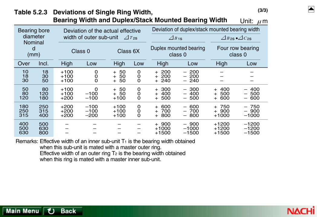
101830
5080
120
180250315
400500630
183050
80120180
250315400
500630800
Over Incl.
Bearing borediameterNominal
d(mm)
Remarks: Effective width of an inner sub-unit T1 is the bearing width obtainedwhen this sub-unit is mated with a master outer ring.Effective width of an outer ring T2 is the bearing width obtainedwhen this ring is mated with a master inner sub-unit.
+100+100+100
+100+100+200
+200+200+200
–––
000
0– 100– 100
– 100– 100– 200
– – –
High Low
Deviation of the actual effectivewidth of outer sub-unit
+ 50+ 50+ 50
+ 50+ 50+100
+100+100+100
–––
000
000
000
–––
High Low
Class 0 Class 6X
2sT
+ 200+ 200+ 240
+ 300+ 400+ 500
+ 600+ 700+ 800
+ 900+1000+1500
– 200– 200– 240
– 300– 400– 500
– 600– 700– 800
– 900– 1000– 1500
High Low
Deviation of duplex/stack mounted bearing width
–––
+ 400+ 500+ 600
+ 750+ 900+1000
+1200+1200+1500
–––
– 400– 500– 600
– 750– 900– 1000
– 1200– 1200– 1500
High Low
•
Duplex mounted bearingclass 0
Four row bearingclass 0
1sB 2sB 2sC
Unit: mTable 5.2.3 Deviations of Single Ring Width, Bearing Width and Duplex/Stack Mounted Bearing Width µ
(3/3)

Table 8.1 Fits vs. Load Characteristics
Table 8.2.1 Bearing Bore (1) Fits for Radial Bearings
Table 8.2.2 Bearing Outside Diameter (1) Fits for RadialBearings
Table 8.3.1 Bearing Bore or Center Washer Bore (1) Fitsfor Thrust Bearings
Table 8.3.2 Bearing Outside Diameter (1) Fits for ThrustBearings
Table 8.4 Shaft Tolerances (1) for Radial Bearings
Table 8.5 Shaft Tolerances for Thrust Bearings
Table 8.6 Housing Bore Tolerances (1) for Radial Bearings(Except Inch-series Tapered Roller Bearings)
Table 8.7 Housing Bore Tolerances for Thrust Bearings
Table 8.8.1 For Bearings with ABMA Classes 4 and 2Table 8.8.2 For Bearings with ABMA Classes 3 and 0
Fits of Inch Series Tapered Roller Bearings with Shafts
Table 8.9.1 For Bearings with ABMA Classes 4 and 2Table 8.9.2 For Bearings with ABMA Classes 3 and 0
Fits of Inch Series Tapered Roller Bearings with Housings
Table 8.10.1 Inner Ring with ShaftTable 8.10.2 Outer Ring with Housing
Amounts of Fits: Radial Bearingswith Tolerance JIS Class 0 (ISO Normal Class)
Table 8.11.1 Inner Ring with ShaftTable 8.11.2 Outer Ring with Housing
Amounts of Fits: Radial Bearingswith Tolerance JIS (ISO) Class 6
Table 8.12.1 Inner Ring with ShaftTable 8.12.2 Outer Ring with Housing
Amounts of Fits: Radial Bearingswith Tolerance JIS (ISO) Class 5
Table 8.13.1 Inner Ring with ShaftTable 8.13.2 Outer Ring with Housing
Amounts of Fits: Radial Bearingswith Tolerance JIS (ISO) Class 4
Amounts of Fits: Thrust Bearingswith Tolerance JIS (ISO) Class 0
Table 8.14.1 Shaft Washer or Center Washer with ShaftTable 8.14.2 Housing Washer with Housing

Rotating condition Type of loadLoad
conditions Inner ring Outer ringFit
Indeterminatedirection load
Interference fit Loose fit
Interference fit Interference fitRotating or
Non-rotatingLoad direction not constant because offluctuation unbalanced load
Table 8.1 Fits vs. Load Characteristics
Non-rotating
Non-rotating
inner ring
outer ring
outer ring
inner ring
Rotating
Rotating
Rotatinginnerring load
Stationaryouterring load
Loose fit Interference fit
Rotatingouterring load
Stationaryinnerring load

j 5j 6
js 6h 5
k 5k 6
m 5m 6n 6p 6r 6
h 4––– m 5 k 4 js 4 h 5 –
h 5h 6
g 5g 6Class 0, class 6
Class 5, class 4
For rotating inner ring load and indeterminate direction loadFor rotatingouter ring load
Fit class vs. load typeBearing toleranceclass
Table 8.2.1 Bearing Bore (1) Fits for Radial Bearings
Bearing toleranceclass
P 7K 6K 7G 7–
––K 5 – – M 5
Class 0, class 6
Class 5, class 4
For rotating inner ring load For rotating outer ring load
Fit class vs. load type
Table 8.2.2 Bearing Outside Diameter (1) Fits for Radial Bearings
J 6J 7
J 6J 7
Js 5
H 6H 7
H 5
For indeterminate direction load
M 7
–
N 7
–
M 7

Bearing toleranceclass
n 6Class 0
For centric axial load
Fit class vs. load type
Table 8.3.1 Bearing Bore or Center Washer Bore (1) Fits for Thrust Bearings
j 6js 6
j 6js 6
For composite load (spherical roller thrust bearing)
m 6 k 6
Bearing toleranceclass
M 7Class 0
For centric axial load
Fit class vs. load type
Table 8.3.2 Bearing Outside Diameter (1) Fits for Thrust Bearings
For composite load (spherical roller thrust bearing)
H 7–
Note: (1) These dimensional fits are based on JIS B 1514.

For all shaft diameters g6
When high precision is required, adopt g5 and h5 respectively. For large bearings, f6 is adopted because of easy bearing movement in axial direction.
Driven wheel
For all shaft diameters h6 Tension pully, rope sheave
Operating conditions
Rotatingouter ring
load
Shaft diameter (mm)
RemarksTolerancesymbols
Examples of application(Reference)Bell bearings Spherical roller
bearings
Cylindrical rollerbearingsTapered rollerbearings
Bearings with cylindrical bore
Table 8.4 Shaft Tolerances (1) for Radial Bearings
When the inner ring is required to move on the shaft easily
When the inner ring is required to move on the shaft easily
Remarks: Heavy load P > 0.12Cr , Normal Load 0.06Cr < P ≤ 0.12Cr , Light Load P ≤ 0.06Cr Cr: Basic Dynamic Load RatingNote: (1) Shaft tolerances in this table are applied to solid steel shaft for bearings with tolerance class 0 and 6.
(1/3)
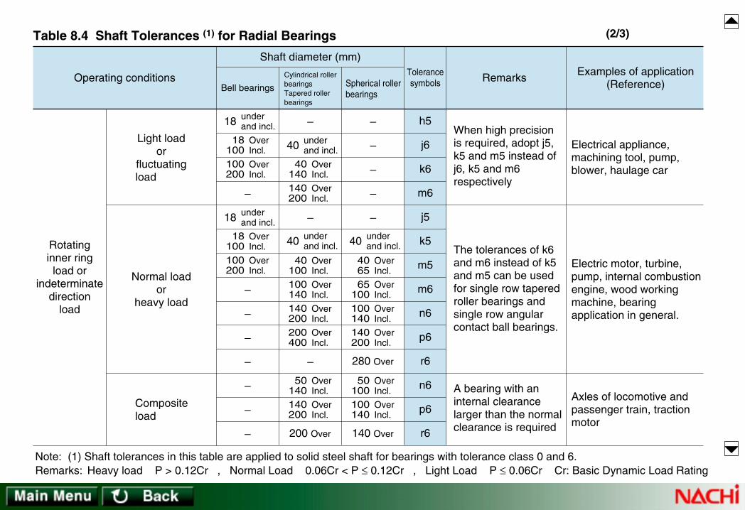
underand incl.
OverIncl.
18 100
OverIncl.
18 100
OverIncl.
100 200
OverIncl.
100 200
OverIncl.
40 140
OverIncl.
140 200
18
underand incl.18
– –
–
–
–
–
–
–
–
–
–
–
–
–
–
–
h5
j6
k6
m6
j5
k5
m5
m6
n6
p6
r6280 Over
140 Over200 Over
n6
p6
r6
When high precision is required, adopt j5, k5 and m5 instead of j6, k5 and m6 respectively
Electrical appliance,machining tool, pump,blower, haulage car
Normal loador
heavy load
Compositeload
The tolerances of k6 and m6 instead of k5 and m5 can be used for single row tapered roller bearings and single row angular contact ball bearings.
Electric motor, turbine, pump, internal combustion engine, wood working machine, bearing application in general.
Light loador
fluctuatingload
Rotatinginner ringload or
indeterminatedirection
load
underand incl.40
OverIncl.
40100
OverIncl.
100 140
OverIncl.
140 200
OverIncl.
200 400
underand incl.40
OverIncl.
4065
OverIncl.
65 100
OverIncl.
100 140
OverIncl.
140 200
OverIncl.
50 140
OverIncl.
50 100
OverIncl.
140 200
OverIncl.
100 140
underand incl.40
A bearing with an internal clearance larger than the normal clearance is required
Axles of locomotive and passenger train, traction motor
Operating conditions
Shaft diameter (mm)
RemarksTolerancesymbols
Examples of application(Reference)Bell bearings Spherical roller
bearings
Cylindrical rollerbearingsTapered rollerbearings
Table 8.4 Shaft Tolerances (1) for Radial Bearings
Remarks: Heavy load P > 0.12Cr , Normal Load 0.06Cr < P ≤ 0.12Cr , Light Load P ≤ 0.06Cr Cr: Basic Dynamic Load RatingNote: (1) Shaft tolerances in this table are applied to solid steel shaft for bearings with tolerance class 0 and 6.
(2/3)

250 under and incl.
250 Over
j6
js6, j6Centric axial load – –
h10/IT7 instead of h9/IT5 can be used for power transmission shaft. IT5 and IT7 mean the form error (out of roundness, taper) should be limited within the tolerance ranges of IT5 and IT7
For all load condition For all shaft conditionRailroad car axle, bearingapplication in generalh9/IT5
Bearing with tapered bore (with sleeve)
Operating conditions
Shaft diameter (mm)
RemarksTolerancesymbols
Examples of application(Reference)Bell bearings Spherical roller
bearings
Cylindrical rollerbearingsTapered rollerbearings
Table 8.4 Shaft Tolerances (1) for Radial Bearings
Remarks: Heavy load P > 0.12Cr , Normal Load 0.06Cr < P ≤ 0.12Cr , Light Load P ≤ 0.06Cr Cr: Basic Dynamic Load RatingNote: (1) Shaft tolerances in this table are applied to solid steel shaft for bearings with tolerance class 0 and 6.
(3/3)
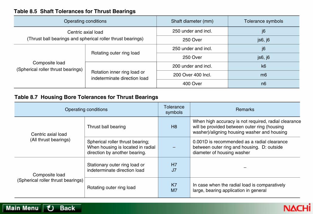
250 under and incl.
250 Over
250 under and incl.
250 Over
200 under and incl.
200 Over 400 Incl.
400 Over
Shaft diameter (mm)
j6
js6, j6
j6
js6, j6
k6
m6
n6
Tolerance symbols
Centric axial load
Operating conditions
(Thrust ball bearings and spherical roller thrust bearings)
Composite load (Spherical roller thrust bearings)
Rotating outer ring load
Rotation inner ring load orindeterminate direction load
Table 8.5 Shaft Tolerances for Thrust Bearings
Spherical roller thrust bearing;When housing is located in radialdirection by another bearing.
Thrust ball bearing
Stationary outer ring load orindeterminate direction load
Rotating outer ring load
When high accuracy is not required, radial clearancewill be provided between outer ring (housingwasher)/aligning housing washer and housing
0.001D is recommended as a radial clearancebetween outer ring and housing. D: outsidediameter of housing washer
In case when the radial load is comparativelylarge, bearing application in general
–
–
H8
K7M7
H7J7
Composite load (Spherical roller thrust bearings)
Centric axial load (All thrust bearings)
Tolerancesymbols
Operating conditions Remarks
Table 8.7 Housing Bore Tolerances for Thrust Bearings

When a heavy load is applied to athin-walled housing or impact load
Normal load or heavy load
Light load or fluctuating load
Heavy impact load
Heavy load or normal load; Whenthe outer ring is not required tomove in axial direction
Normal load or light load; When itis desirable that the outer ring canbe moved in axial direction
Impact load; When no-loadcondition occurs instantaneously
All kinds of load
Normal load or light load
When thermal conduction throughthe shaft is caused
N7
P7
M7
K7
J7
H7
H8
G7
Outer ring can notbe moved in axial direction.
Outer ring can not bemoved in axialdirection as a rule.
Outer ring can bemoved in axialdirection.
Outer ring can bemoved easily inaxial direction.
Automotive wheel (ball bearing)
Automotive wheel (roller bearing)
Conveyer roller, pulley, tension pulley
Traction motor
Electric motor, pump, crank shaft
Electric motor, pump, crank shaft
Railroad car axle
Railroad car axle, bearing applicationin general
Gear transmission
Paper mill (Drying cylinder)
Rotating outerring load
Indeterminatedirection load
Rotating innerring load
Table 8.6 Housing Bore Tolerances (1) for Radial Bearings (Except Inch-series Tapered Roller Bearings)
Operating conditions Tolerancesymbols
Outer ring movement Examples of application (Reference)
Note: (1) The tolerances in this table are applied to cast iron or steel housing for bearings with tolerance class 0 and 6. Tighter fit is adopted for light alloy housing. (2) Outer ring of non-separable bearing
Monoblockhousing
Monoblockor split
housing
(2)
(1/2)

Fluctuating load; When extremelyaccurate rotation and high rigidityare required
Indeterminate direction light load;When extremely accurate rotationis required.
When extremely accurate rotation isrequired and it is desirable that the outerring can be moved in axial direction.
N6
M6
K6
J6
Outer ring can notbe moved in axialdirection.
Outer ring can not bemoved in axialdirection as a rule.
Outer ring can bemoved in axialdirection.
Main shaft of grinding machine, ball bearing ongrinding wheel side High speed centrifugalcompressor, clamping side bearing
Main shaft of machine tool (roller bearing outside diameter is under and including 125 mm)
Main shaft of machine tool(roller bearing, outside diameter is over 125 mm)
Main shaft of grinding machine, ball bearing ondriving side High speed centrifugal compressor,floating side bearing
When extremelyhigh accuracy is
required
Table 8.6 Housing Bore Tolerances (1) for Radial Bearings (Except Inch-series Tapered Roller Bearings)
Operating conditions Tolerancesymbols Outer ring movement Examples of application (Reference)
Note: (1) The tolerances in this table are applied to cast iron or steel housing for bearings with tolerance class 0 and 6. Tighter fit is adopted for light alloy housing. (2) Outer ring of non-separable bearing
Monoblockhousing
(2)
(2/2)

Single row, radial ball bearings
Double row, radial ball bearings
Cylindrical roller bearings
Spherical roller bearings
Bore No. d
Bearing borediameterNominal
Bea
ring
outs
ide
diam
eter
D
Bea
ring
outs
ide
diam
eter
D
Chamferdimension
Chamferdimension
Diameter series 9 Diameter series 0
Dimension series
Width series
rminWidth B
09 19 29 39 49 59 69 0919
39
~
49
69
~
0 1 2 3 4 5 6Dimension series
rminWidth B
Width series
10
60
~ 00 10 20 30 40 50 60 00
0 1 2 3 4 5 6
240230
NN30N10
6070
6979 160
239
NN49
00 01 02
03 04 /22
05 /28 06
/32 07 08
10 12 15
17 20 22
25 28 30
32 35 40
222428
303739
424547
525562
ñ ñ ñ
ñ 77
777
778
667
799
999
101012
131313
131717
171717
202022
ñññ
ñ0.30.3
0.30.30.3
0.30.30.3
0.30.30.3
0.30.30.3
0.30.30.3
0.60.60.6
262832
354244
475255
586268
ñ 78
888
889
999
101011
121414
141516
161718
161617
182222
222425
262728
ñ0.30.3
0.30.30.3
0.30.30.3
0.30.30.3
0.30.30.3
0.30.60.6
0.60.61
111
8 8 8.5
8.51111
111111
131314
101010
101313
131313
151516
161618
182323
232323
272730
222223
233030
303030
363640
0.30.30.3
0.30.30.3
0.30.30.3
0.60.60.6
889
101212
121213
131415
121213
141616
161819
202021
212123
243030
303234
353638
292930
324040
404345
474850
Remarks: 1. rmin is the smallest chamfer dimension.2. The chamfer dimensions given in this table do not necessarily apply to:
(1) the groove side of bearing rings with snap ring groove(2) the flangeless side of thin cylindrical roller bearing rings
(3) the front face side of angular contact bearing(4) inner rings of bearings with tapered bore
Table 4.2.1 Boundary Dimensions of Diameter Series 9, 0 (2/8) Unit : mm

Single row, radial ball bearings
Double row, radial ball bearings
Cylindrical roller bearings
Spherical roller bearings
Bore No. d
Bearing borediameterNominal
Bea
ring
outs
ide
diam
eter
D
Bea
ring
outs
ide
diam
eter
D
Chamferdimension
Chamferdimension
Diameter series 9 Diameter series 0
Dimension series
Width series
rminWidth B
09 19 29 39 49 59 69 0919
39
~
49
69
~
0 1 2 3 4 5 6Dimension series
rminWidth B
Width series
10
60
~ 00 10 20 30 40 50 60 00
0 1 2 3 4 5 6
240230
NN30N10
6070
6979 160
239
NN49
09 10 11
12 13 14
15 16 17
18 19 20
45 50 55
60 65 70
75 80 85
90 95
100
687280
8590
100
105110120
125130140
889
99
10
101011
111113
121213
131316
161618
181820
222225
252530
303035
353540
0.30.30.3
0.30.30.6
0.60.60.6
0.60.60.6
0.60.61
111
111.1
1.11.11.1
758090
95100110
115125130
140145150
101011
111113
131414
161616
191922
222224
242727
303030
303035
353540
404545
505050
0.60.60.6
0.60.60.6
0.60.60.6
111
111.1
1.11.11.1
1.11.11.1
1.51.51.5
141416
161619
191922
222224
161619
191923
232326
262630
303034
343440
404046
464654
404045
454554
545463
636371
0.60.61
111
111.1
1.11.11.1
161618
181820
202222
242424
232326
262630
303434
373737
404046
464654
546060
676767
545463
636371
718080
909090
Remarks: 1. rmin is the smallest chamfer dimension.2. The chamfer dimensions given in this table do not necessarily apply to:
(1) the groove side of bearing rings with snap ring groove(2) the flangeless side of thin cylindrical roller bearing rings
(3) the front face side of angular contact bearing(4) inner rings of bearings with tapered bore
Table 4.2.1 Boundary Dimensions of Diameter Series 9, 0 (3/8) Unit : mm

+25+25+25+51+76
+25+25+25+51+76
+25+25+25+51+76
+25+25+25+51+76
00000
00000
00000
00000
+ 76+ 76+ 76+152+229
+ 25+ 25+ 51+ 76+127
– 13– 25– 25– 25– 25
– 13– 25– 25– 25– 25
+ 50+ 50+ 50+102+152
000
+ 26+ 51
– 39– 51− 51– 76–102
– 39– 51– 51– 76–102
25L25L25L51L76L
25T25T25T25T25T
64T76T76T
127T178T
64T76T76T
127T178T
76L76L76L
152L229L
25L25L51L76L
127L
13T25T25T25T25T
13T25T25T25T25T
76.2127.0304.8609.6914.4
76.2127.0304.8609.6914.4
76.2127.0304.8609.6914.4
76.2127.0304.8609.6914.4
–76.2
127.0304.8609.6
–76.2
127.0304.8609.6
–76.2
127.0304.8609.6
–76.2
127.0304.8609.6
Floating side orClamping side
Outer ring location inaxial direction can beadjusted
Over Incl. High Low High Low Max Min
Amounts (1)Bearing outsidediameter deviation
Housing borediameter deviation
Bearing outside diameterNominal D (mm)Operating conditions
Table 8.9.1 For Bearings with ABMA Classes 4 and 2 Unit: m
Table 8.9 Fits of Inch Series Tapered Roller Bearings with Housings
Outer ring location inaxial direction cannot be adjusted
Outer ring location inaxial direction cannot be adjusted
Rotatinginnerringload
Rotatingouterringload
Note: (1) T: Tight fit L: Loose fit
µ

+13+13+25+38
+13+13+25+38
+13+13+25+38
+13+13+25+38
+13+13+25+38
0000
0000
0000
0000
0000
+38+38+64+89
+25+25+51+76
+13+25+25+38
0000
–13–13–13–13
+26+26+38+51
+13+13+25+38
0000
–12–25–26–38
–25–38–39–51
13L13L13L13L
0 0 0 0
13T13T25T38T
25T38T51T76T
38T51T64T89T
38L38L64L89L
25L25L51L76L
13L25L25L38L
0 0 0 0
13T13T13T13T
152.4304.8609.6914.4
152.4304.8609.6914.4
152.4304.8609.6914.4
152.4304.8609.6914.4
152.4304.8609.6914.4
–152.4304.8609.6
–152.4304.8609.6
–152.4304.8609.6
–152.4304.8609.6
–152.4304.8609.6
Clamping side
Outer ring location inaxial direction can beadjusted
Table 8.9.2 For Bearings with ABMA Classes 3 and 0 Unit: m
Outer ring location inaxial direction cannot be adjusted
Normal loadOuter ring location inaxial direction cannot be adjusted
Floating side
Rotatinginnerringload
Rotatingouterringload
Note: (1) T: Tight fit L: Loose fit (2) This tables is not applied to the bearing with tolerance class 0 whose bore diameter is over 304.8 mm.
Over Incl. High Low High Low Max Min
Amounts (1)Bearing outsidediameter deviation
Housing borediameter deviation
Bearing outside diameterNominal D (mm)Operating conditions
µ

36
10
18305080
120140160
180200225
250280
315355
400450
61018
305080
120
140160180
200225250
280315
355400
450500
Over Incl. High
Nominal
diameter
(mm)
Table 8.10.1 Inner Ring with Shaft Unit: m
– 8– 8– 8
–10–12–15–20
–25
–30
–35
–40
–45
–––
–323948
58
67
–
–
–
–––
– 91113
15
17
–
–
–
––17
21253038
46
54
–
–
–
––1
2223
3
4
–
–
–
111213
15182126
–
–
–
–
–
223
4579
–
–
–
–
–
8 8 8
10121520
25
30
35
40
45
5 6 8
9111315
18
20
23
25
27
Low Max Min Max Min Max Max Max Max
Single planemean borediameterdeviationof bearing
Tight Tight Loose Loose LooseTight Tight Tight
m5 k5 j5 h5
4 3 2
3 3 5 8
11
15
18
22
25
91114
16202327
32
35
40
43
47
Max Max
g5
Shaft with tolerance grade IT5
mpd
000
0000
0
0
0
0
0
µ
Table 8.10 Amounts of Fits: Radial Bearings with Tolerance JIS Class 0 (ISO Normal Class)
(1/2)

36
10
18305080
120140160
180200225
250280
315355
400450
61018
305080
120
140160180
200225250
280315
355400
450500
Over Incl.
Nominal
diameter
(mm)
Table 8.10.1 Inner Ring with Shaft Unit: m
LooseLooseLoose TightTightTight
–––
––––
113115118
136139143
161165
184190
211217
–––
––––
63 65 68
77 80 84
94 98
108114
126132
Max Min
Tight
r6
–––
–––
76
93
109
123
138
–
–––
–––37
43
50
56
62
–
Max Min
Tight
p6
–––
–455465
77
90
–
–
–
–––
–172023
27
31
–
–
–
Max Min
Tight
n6
–––
–374555
65
76
–
–
–
–––
– 91113
15
17
–
–
–
Max Min
Tight
m6
––20
25303645
53
63
–
–
–
––1
2223
3
4
–
–
–
Max Min
Tight
k6
141516
19232733
39
46
51
58
65
2 2 3
4 5 7 9
11
13
16
18
20
Max Max
j6
8 8 8
10121520
25
30
35
40
45
8 911
13161922
25
29
32
36
40
Max Max
h6
4 3 2
3 3 5 8
11
15
18
22
26
121417
20252934
39
44
49
54
60
Max Max
g6
Shaft with tolerance grade IT6
µ
Table 8.10 Amounts of Fits: Radial Bearings with Tolerance JIS Class 0 (ISO Normal Class)
(2/2)

61018
305080
120150180
250315400
101830
5080
120
150180250
315400500
Over Incl.
Nominal
diameter
(mm)
Table 8.10.2 Outer Ring with Housing Unit: m
000
000
000
000
– 8– 8– 8
–11–13–15
–18–25–30
–35–40–45
455
666
777
777
131417
212631
364352
606978
High Low Max Max
J6
Housing with tolerance grade IT6
LooseTight Tight
7 911
131518
212124
272932
101011
141719
222935
404753
Max Max
K6
LooseTight
000
000
000
000
171922
273237
435059
677685
H6
Loose
MaxMax
mpD
Single plane meanoutside diameter
deviationof bearing
µ
Table 8.10 Amounts of Fits: Radial Bearings with Tolerance JIS Class 0 (ISO Normal Class)
(1/2)

61018
305080
120150180
250315400
101830
5080
120
150180250
315400500
Over Incl.
Nominal
diameter
(mm)
Table 8.10.2 Outer Ring with Housing Unit: m
242935
425159
686879
8898
108
135
689
10 33
110
Max Min
Tight Tight Tight Tight Tight Tight
P7
Housing with tolerance grade IT7
192328
333945
526060
667380
4 3 2
3 4 5
61316
212428
N7
Loose
MaxMax
151821
253035
404046
525763
8 8 9
111315
182530
354045
M7
Loose
MaxMax
101215
182125
282833
364045
131415
182225
303743
515763
K7
Loose
MaxMax
7 8 9
111213
141416
161820
161821
253137
445160
717988
J7
Loose
MaxMax
000
000
000
000
232630
364350
586576
8797
108
H7
Loose
MaxMax
5 6 7
91012
141415
171820
28 32 37
45 53 62
72 79 91
104115128
G7
Loose
MaxMin
µ
Table 8.10 Amounts of Fits: Radial Bearings with Tolerance JIS Class 0 (ISO Normal Class)
(2/2)

36
10
18305080
120140160
180200225
61018
305080
120
140160180
200225250
Over Incl.
Nominal
diameter
(mm)
Table 8.11.1 Inner Ring with Shaft Unit: m
000
0000
0
0
– 7– 7– 7
– 8–10–12–15
–18
–22
–––
–303643
51
59
–––
– 91113
15
17
––16
19232733
39
46
––1
2223
3
4
101112
13161821
–
–
223
4579
–
–
7 7 7
8101215
18
22
5 6 8
9111315
18
20
High Low Max Min Max Min Max Max Max Max
Tight Tight Tight TightTight Loose Loose Loose
m5 k5 j5 h5
321
1123
4
7
91114
16202327
32
35
Max Max
g5
Shaft with tolerance grade IT5Single planemean borediameterdeviationof bearing
mpd
µ
Table 8.11 Amounts of Fits: Radial Bearings with Tolerance JIS (ISO) Class 6
(1/2)
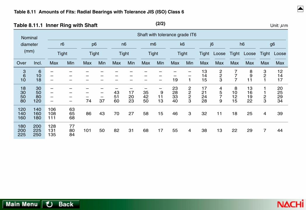
36
10
18305080
120140160
180200225
61018
305080
120
140160180
200225250
Over Incl.
Nominal
diameter
(mm)
Table 8.11.1 Inner Ring with Shaft Unit: m
Loose Loose Loose
–––
––––
106108111
128131135
–––
––––
63 65 68
77 80 84
Max Min
Tight
r6
–––
–––
74
86
101
–––
–––37
43
50
Max Min
Tight
p6
–––
–435160
70
82
–––
–172023
27
31
Max Min
Tight
n6
–––
–354250
58
68
–––
– 91113
15
17
Max Min
Tight
m6
––19
23283340
46
55
––1
2223
3
4
Max Min
Tight Tight TightTight
k6
131415
17212428
32
38
2 2 3
4 5 7 9
11
13
Max Max
j6
7 7 7
8101215
18
22
8 911
13161922
25
29
Max Max
h6
321
1123
4
7
121417
20252934
39
44
Max Max
g6
Shaft with tolerance grade IT6
µ
Table 8.11 Amounts of Fits: Radial Bearings with Tolerance JIS (ISO) Class 6
(2/2)
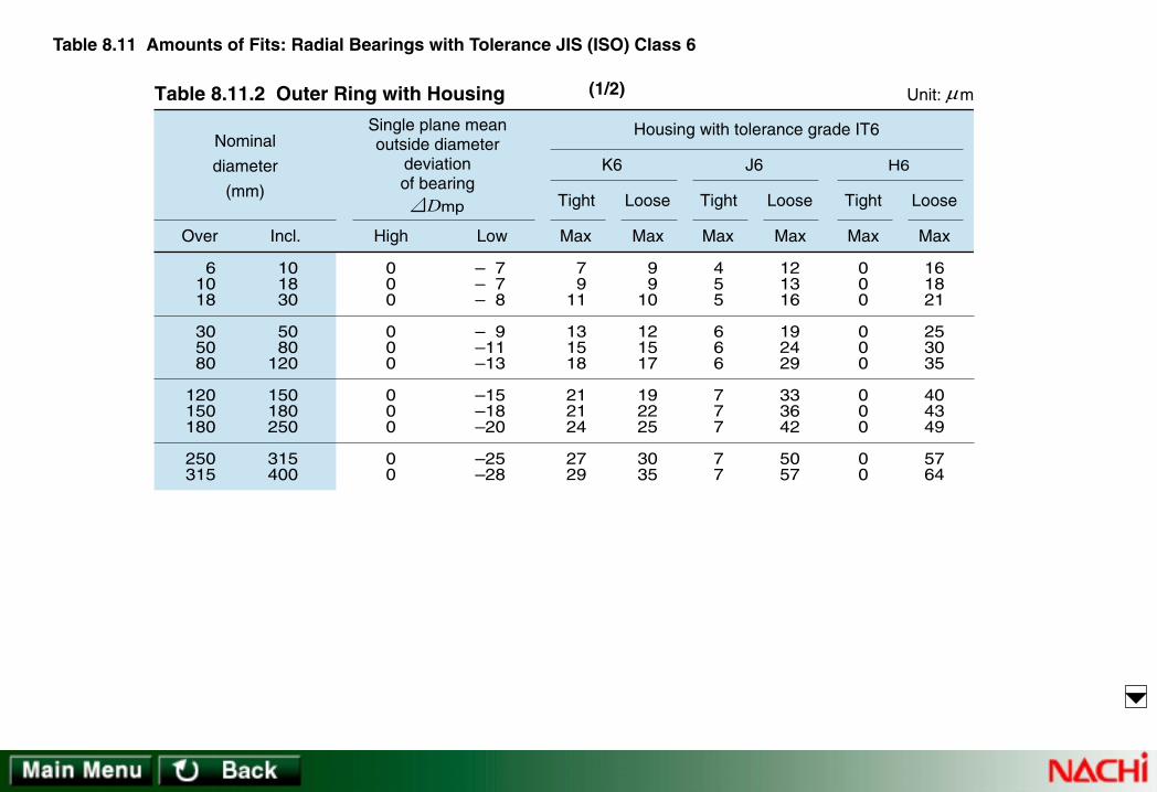
61018
305080
120150180
250315
101830
5080
120
150180250
315400
Over Incl.
Nominal
diameter
(mm)
Table 8.11.2 Outer Ring with Housing Unit: m
000
000
000
00
– 7– 7– 8
– 9–11–13
–15–18–20
–25–28
455
666
777
77
121316
192429
333642
5057
High Low Max Max
J6
Housing with tolerance grade IT6
LooseTight Tight Tight
7 911
131518
212124
2729
9 910
121517
192225
3035
Max Max
K6
Loose
000
000
000
00
161821
253035
404349
5764
H6
Loose
MaxMax
mpD
Single plane meanoutside diameter
deviationof bearing
µ
Table 8.11 Amounts of Fits: Radial Bearings with Tolerance JIS (ISO) Class 6
(1/2)

61018
305080
120150180
250315
101830
5080
120
150180250
315400
Over Incl.
Nominal
diameter
(mm)
Table 8.11.2 Outer Ring with Housing Unit: m
242935
425159
686879
8898
2 4 6
81011
131013
1113
Max Min
Tight TightTightTightTightTight
P7
Housing with tolerance grade IT7
192328
333945
526060
6673
3 2 1
1 2 3
3 6 6
1112
N7
Loose
MaxMax
151821
253035
404046
5257
7 7 8
91113
151820
2528
M7
Loose
MaxMax
101215
182125
282833
3640
121314
162023
273033
4145
K7
Loose
MaxMax
7 8 9
111213
141416
1618
151720
232935
414450
6167
J7
Loose
MaxMax
000
000
000
00
222529
344148
555866
7785
H7
Loose
MaxMax
5 6 7
91012
141415
1718
27 31 36
43 51 60
69 72 81
94103
G7
Loose
MaxMin
µ
Table 8.11 Amounts of Fits: Radial Bearings with Tolerance JIS (ISO) Class 6
(2/2)

36
10
183050
80120180
61018
305080
120180250
000
000
000
– 5– 5– 5
– 6– 8– 9
–10–13–15
131517
202428
334046
4 6 7
8 911
131517
Over Incl. High Low Max Min
Tight
m4Nominal
diameter
(mm)
Shaft with tolerance grade IT4
Table 8.12.1 Inner Ring with Shaft Unit: m
Table 8.12 Amounts of Fits: Radial Bearings with Tolerance JIS (ISO) Class 5
Max Max
h5
5 6 8
91113
151820
5 5 5
6 8 9
101315
101011
141719
232833
111
222
334
Max Min
Tight TightTightTight Loose Loose Loose
k4
Max Max
js4
2 2 2.5
3 3.54
5 6 7
7 7
7.5
9 11.513
15 19 22
Max Max
h4
141720
232833
384652
4 6 7
8 911
131517
Max Min
Tight
m5
5 5 5
6 8 9
101315
4 4 5
6 7 8
101214
Shaft with tolerance grade IT5Single planemean borediameterdeviationof bearing
mpd
µ

Table 8.12 Amounts of Fits: Radial Bearings with Tolerance JIS (ISO) Class 5
61018
305080
120150180
250315
101830
5080
120
150180250
315400
000
000
000
00
– 5– 5– 6
– 7– 9–10
–11–13–15
–18–20
Over Incl. High Low
Nominal
diameter
(mm)
Housing with tolerance grade IT5
Table 8.12.2 Outer Ring with Housing Unit: m
Max Max
H5
000
000
000
00
111315
182225
293135
4145
LooseTight
Max Max
Js5
3 4
4.5
5.5 6.5 7.5
9 9
10
11.512.5
8 9
10.5
12.515.517.5
20 22 25
29.532.5
LooseTight
Max Max
K5
5 6 8
91013
151518
2022
6 7 7
91212
141617
2123
LooseTight
Max Max
M5
101214
161923
272731
3639
111
232
244
56
LooseTightmpD
Single plane meanoutside diameter
deviationof bearing
µ

36
10
183050
80120180
61018
305080
120180250
000
000
000
– 4– 4– 4
– 5– 6– 7
– 810
–12
121416
192226
313743
4 6 7
8 911
131517
Over Incl. High Low Max Min
Tight
m4Nominal
diameter
(mm)
Shaft with tolerance grade IT4
Table 8.13.1 Inner Ring with Shaft Unit: m
Table 8.13 Amounts of Fits: Radial Bearings with Tolerance JIS (ISO) Class 4
Max Max
h5
5 6 8
91113
151820
4 4 4
5 6 7
81012
9 910
131517
212530
111
222
334
Max Min
Tight
k4
Max Max
js4
2 2 2.5
3 3.54
5 6 7
6 6 6.5
8 9.5
11
13 16 19
Max Max
h4
131619
222631
364349
4 6 7
8 911
131517
Max Min
TightTight Loose Loose LooseTight Tight
m5
4 4 4
5 6 7
81012
4 4 5
6 7 8
101214
Shaft with tolerance grade IT5Single planemean borediameterdeviationof bearing
mpd
µ

Table 8.13 Amounts of Fits: Radial Bearings with Tolerance JIS (ISO) Class 4
61018
305080
120150180
250315
101830
5080
120
150180250
315400
000
000
000
00
– 4– 4– 5
– 6– 7– 8
– 9–10–11
–13–15
Over Incl. High Low
Nominal
diameter
(mm)
Housing with tolerance grade IT5
Table 8.13.2 Outer Ring with Housing Unit: m
Max Max
H5
000
000
000
00
101214
172023
272831
3640
LooseTight
Max Max
Js5
3 4
4.5
5.5 6.5 7.5
9 9
10
11.512.5
7 8
9.5
11.513.515.5
18 19 21
24.527.5
LooseTight
Max Max
K5
5 6 8
91013
151518
2022
5 6 6
81010
121313
1618
LooseTight
Max Max
M5
101214
161923
272731
3639
000
110
010
01
LooseTightmpD
Single plane meanoutside diameter
deviationof bearing
µ
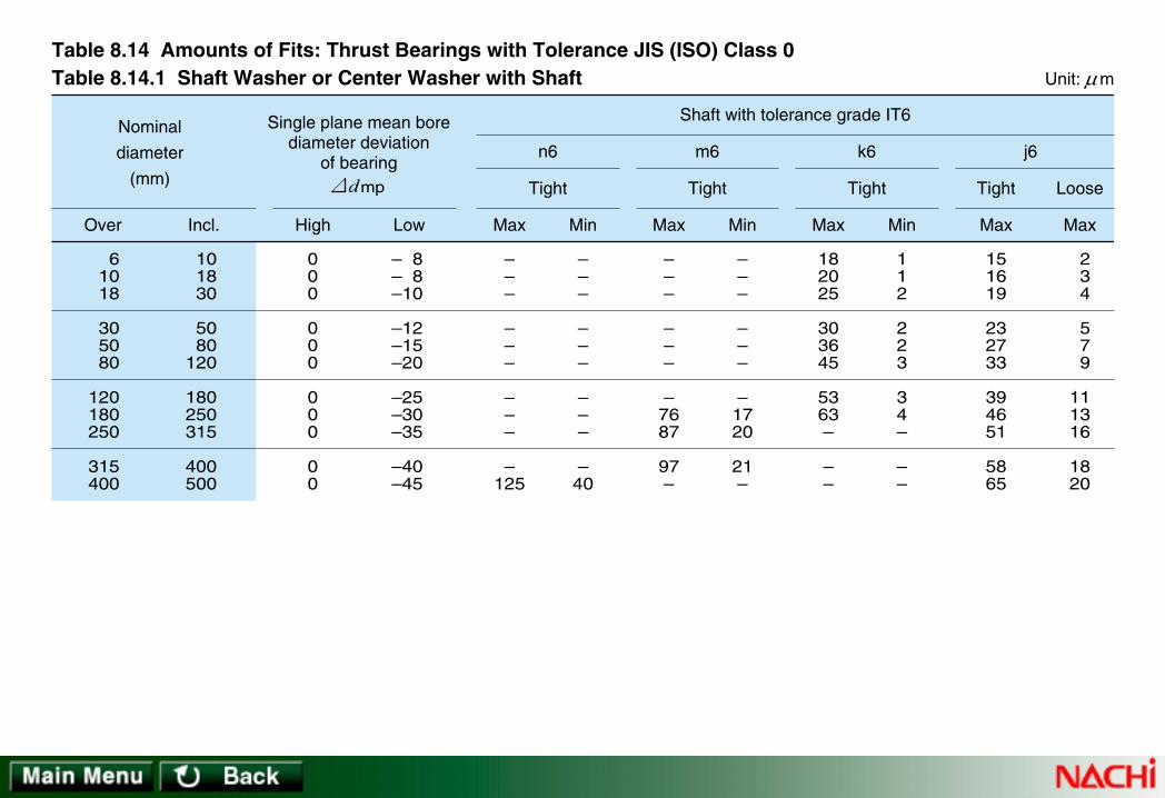
61018
305080
120180250
315400
101830
5080
120
180250315
400500
000
000
000
00
– 8– 8–10
–12–15–20
–25–30–35
–40–45
Over Incl. High Low
Nominal
diameter
(mm)
Shaft with tolerance grade IT6
Table 8.14.1 Shaft Washer or Center Washer with Shaft Unit: m
Table 8.14 Amounts of Fits: Thrust Bearings with Tolerance JIS (ISO) Class 0
Max Max
j6
151619
232733
394651
5865
2 3 4
5 7 9
111316
1820
LooseTight
Max Min
k6
182025
303645
5363–
––
112
223
34–
––
Tight
Max Min
m6
–––
–––
–7687
97–
–––
–––
–1720
21–
Tight
Max Min
n6
–––
–––
–––
–125
–––
–––
–––
–40
Tight
Single plane mean borediameter deviation
of bearingmpd
µ

Table 8.14 Amounts of Fits: Thrust Bearings with Tolerance JIS (ISO) Class 0
101830
5080
120
180250315400
183050
80120180
250315400500
000
000
0000
–11–13–16
–19–22–25
–30–35–40–45
Over Incl. High Low
Nominal
diameter
(mm)
Housing with tolerance grade IT7
Table 8.14.2 Housing Washer with Housing Unit: m
Max Max
H7
000
000
0000
293441
495765
768797
108
LooseTight
Max Max
M7
182125
303540
46525763
111316
192225
30354045
LooseTightmpD
Single plane mean outsidediameter deviation
of bearing
µ