NBC-Catalogue.pdf - BTC bearing
144
-
Upload
khangminh22 -
Category
Documents
-
view
0 -
download
0
Transcript of NBC-Catalogue.pdf - BTC bearing


CATALOGUE/TC-106, JULY 2017


4.2 NEI Life Enhancement For Rolling Bearing
4.3 Modified rating life
4.4
4.5


4.2 NEI Life Enhancement For Rolling Bearing
In addition to design parameters the service life of rolling bearings can be greatly enhanced by material and heat treatment processes, thereby influencing the grain structure of the steel with surface modifications. A special heat treatment is given to the bearings there by eectively, alter the microstructure which in turns improves the yield strength and rolling contact fatigue properties. The special heat treatment process leverages the combined advantage of having modified surface and core microstructure to significantly extend the bearing life. To prove the eectiveness of bearing made from special manufacturing process extensive laboratory and field tests were carried out. The positive results from the test helped in deciding the life multiplication factor for NEI bearings. However the selection of the special treatments depends on the application and type of bearing. Consult NEI representative for additional information and support. Please refer the table below for special treatment factors
Special Treatment
Life Multiplication Factor
TS2
4T
TMB
TM
AST
ASTB
MLB
1
1.4
2.2
2
2
3
4
The rating life modified for 90% or other reliability considering fatigue load, and/or special bearing properties, and/or contaminated lubricant and other non -conventional operating conditions.The modified rating life is calculated according to the formula prescribed in ISO281:2007.
4.3 Modified rating life (L )nm
Lnm = a1a ISO L 10
6L modified rating life [10 revolutions] nm
a reliability adjustment factor (refer to 4.1.1.1on page 9)1
a life modification factor for operating conditionsISO
This method evaluates the bearing life by using the life modification factor (a ) and the life adjustment factor for ISO
reliability (a ), that are dependent on the type, size and 1
internal geometry of the bearing, the manufacturing quality, the fatigue limit of the raceway material, lubrication method, type of lubricant, viscosity, additives, cleanliness and filtration, operating temperature and bearing speed. The life modification factor( a ) can be ISO
estimated from graphs and equations given in ISO281:2007 standard.
a ISO = fec Cu ,k
P
Whereec Contamination factorCu Fatigue load limit in newtonsK Viscosity ratio(kappa)P Dynamic Equivalent load in newtons
4.3.1 Fatigue load limit (C )u
The fatigue load limit (Cu) is calculated according to ISO
281 :2007 and is defined as the load below which, under
laboratory conditions, no fatigue occurs in the material or
the load at which the fatigue stress limit just reached the
most heavily loaded raceway contact. This load depends
on the pitch diameter of the rolling elements and the basic
static load rating.The formula for calculation for fatigue
load limit (C ) is given below:u
For Ball bearing:
Cu
=
Co
22
for bearings with Dpw < 100 mm
for bearings with Dpw <100 mm
Cu
= ))100
Dpw
0.5
Co
22
= for bearings with Dpw < 100 mmCu
Co
8.2
CuCo
8.2for bearings with Dpw <100 mm= ))100
Dpw
0.3
For Roller bearing :
where
Co is the basic static load rating in newton
D is the pitch diameter of ball or roller set in mmpw
The life modification factor( a ) is a function of ISO
11
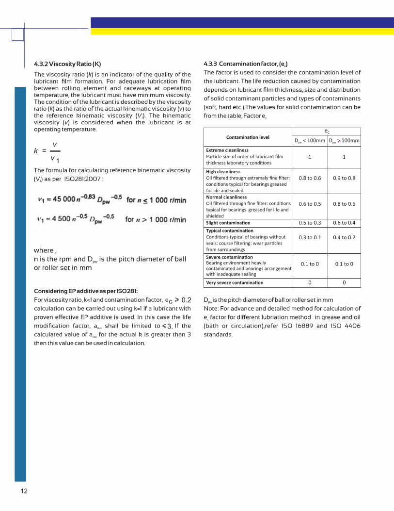
4.3.2 Viscosity Ratio (K)
The viscosity ratio (k) is an indicator of the quality of the lubricant film formation. For adequate lubrication film between rolling element and raceways at operating temperature, the lubricant must have minimum viscosity. The condition of the lubricant is described by the viscosity ratio (k) as the ratio of the actual kinematic viscosity (v) to the reference kinematic viscosity (V ). The kinematic 1
viscosity (v) is considered when the lubricant is at operating temperature.
kv
v 1
=
The formula for calculating reference kinematic viscosity
(V ) as per ISO281:2007 :1
where ,n is the rpm and D is the pitch diameter of ballpw
or roller set in mm
Considering EP additive as per ISO281:
For viscosity ratio, k<1 and contamination factor,
calculation can be carried out using k=1 if a lubricant with
proven eective EP additive is used. In this case the life
modification factor, a shall be limited to If the iso
calculated value of a for the actual k is greater than 3 iso
then this value can be used in calculation.
0.2ec <
3.<
4.3.3 Contamination factor, (e )c
The factor is used to consider the contamination level of
the lubricant. The life reduction caused by contamination
depends on lubricant film thickness, size and distribution
of solid contaminant particles and types of contaminants
(soft, hard etc.).The values for solid contamination can be
from the table, Factor ec
D is the pitch diameter of ball or roller set in mmpw
Note: For advance and detailed method for calculation of
e factor for dierent lubriation method in grease and oil c
(bath or circulation),refer ISO 16889 and ISO 4406
standards.
Contamina�on level
Extreme cleanliness Par�cle size of order of lubricant filmthickness laboratory condi�ons
High cleanlinessOil filtered through extremely fine filter:condi�ons typical for bearings greasedfor life and sealed
Normal cleanliness Oil filtered through fine filter: condi�onstypical for bearings greased for life andshielded
Slight contamina�on
Typical contamina�on Condi�ons typical of bearings withoutseals: course filtering: wear par�clesfrom surroundings
Severe contamina�onBearing environment heavily contaminated and bearings arrangementwith inadequate sealing
Very severe contamina�on
D < 100mmpw D > 100mmpw
ec
1
0.9 to 0.8
0.8 to 0.6
0.6 to 0.4
0.4 to 0.2
0.1 to 0
0
1
0.8 to 0.6
0.6 to 0.5
0.5 to 0.3
0.3 to 0.1
0.1 to 0
0
12

13

14

15

16

17

18

19

20

21

22
23

24

25

26
27

28

29

30
31

32

33

34

35

36

37

38

39

40

41

42

43

44

45

46

47
48

49

50

51

52

53

54

55

56
57

58

59

60

61

62

63

64

65

66
67

68

69

70

71

72

73
74

75

76

77

78

79

80

81
82

83

84
85

86

87

88

89

90
91

92

93

94
95
96

97

98
99

100
101

102

103

104

105

106

107

108

109

110

111

112

113

114

115

116

117

118

119

120

121

122
123

124

125
126

127

128
d D b B BEARING SIZEDYNAMIC
C
STATIC
Co
BOUNDARY DIMENSION (mm ) LOAD RATING (N)
119.063 195.263 142.9 217.1 CTRB 5x9 CLASS 'C' * 684000 1 109000
131.75 207.963 152.4 225.4 CTRB 5 1/2X10 CLASS 'D' * 724000 1232160
144.45 220.663 163.5 241.3 CTRB 6X11 CLASS 'E' ** 774000 1347810
157.15 252.413 184.2 273.1 CTRB 6 1/2X12 CLASS 'F' *** 1052000 1825000
157.15 249.87 160 216.6 CTRB 6 1/2X9 CLASS 'K' *** 1052000 1825000
* AVAILABLE WITH STEEL CAGE ONLY
** AVAILABLE WITH BOTH STEEL & POLYAMIDE CAGE
*** AVAILABLE WITH POLYAMIDE CAGE ONLY

129
NOTE:- AVAILABLE WITH POLYAMIDE CAGE ONLY
d D b B BEARING SIZEDYNAMIC
C
STATIC
Co
130 230 160 177 UIC130X230 852000 1636000
BOUNDARY DIMENSION (mm ) LOAD RATING (N)

130

131

132

133

134