Advanced Information Processing System - NASA Technical ...
186
* - NASA Contractor Report 181767 Advanced Information Processing System: Local System Services LauraBurkhardt Linda Alger Roy Whittredge Peter Stasiowski THE CHARLES STARK DRAPER LABORATORY, INC. CAMBRIDGE, MA 02139 Contract NAS 1-18061 April 1989 National Aeronautics and Space Ad mi nistra t (on Langley Research Center Hampton. Virginia 23665-5225 ~~ ~ (LASA-CR-181767) ACVLICEL IhkCSEAliUN 1589-2 lSES EICCESSlkG SPETIb: LOCAL SYSSIEC SELVICES (Lraper (CharleE Ztark) Laf;.) 190 fCSCL C9B Uriclas G3/62 0200059
-
Upload
khangminh22 -
Category
Documents
-
view
1 -
download
0
Transcript of Advanced Information Processing System - NASA Technical ...

* -
NASA Contractor Report 181767
Advanced Information Processing System: Local System Services
LauraBurkhardt Linda Alger Roy Whittredge Peter Stasiowski
THE CHARLES STARK DRAPER LABORATORY, INC. CAMBRIDGE, MA 02139
Contract NAS 1-18061 April 1989
National Aeronautics and Space Ad mi nist ra t (on
Langley Research Center Hampton. Virginia 23665-5225
~~
~ (LASA-CR-181767) A C V L I C E L I h k C S E A l i U N 1589-2 lSES
EICCESSlkG SPETIb: LOCAL SYSSIEC SELVICES (Lraper (CharleE Ztark) L a f ; . ) 190 fCSCL C9B Uriclas
G3/62 0200059

TABLE OF CONTENTS
section page
LLST OF ILLUSI.RATIONS ................................................................. 1.0 ~ O D U ~ O N ............................................................................. 1
1.1 A I P S M ~ ....................................................................... 1 1.1.1 A I H Fault Tolerant Processols: Overview ............................... 4 1.1.2 FaultTolerantProcessor: FunctionalViw ................................ 6 AIPS System Software ............................................................... 10 1.2.1 Alps Software Design Approach ......................................... 10 1.2.2 AIPSSystemSof€wareOverview ......................................... 13
1.2.2.1 LocalSystemSenices ......................................... 13 1.2.2.2 Inter-Computer System Services .............................. 15
1.2.2.4
1.2
1.2.2.3 SystemManager ................................................ 16 YO System Services ............................................ 17
2.0 GPC-TION .................................................................... 21 2.1 2.2 GPC Initialization Software Specifications ......................................... 22
GPC Initialization Functional Requirements and M g n ......................... 21
3.0 REAL, TIME OPERATING SYSIEM .................................................... 25 3.1 Real Time Operating System Functional Requirements ........................... 25
3.1.1 Task Execution Management ............................................... 26 3.1.2 MemoryManagement ....................................................... 27 3.1.3 Intertaskcommunication ................................................... 27 3.1.4 Software Exceptions ........................................................ 27 Real Time Operating System Soffware Specifications ............................ 28
Task Execution Management procesS Descriptions ..................... 28
Intertask Communication Process Descriptions ......................... 41
3.2 3.2.1 3.2.2 3.2.3 3.2.4
Memory Management pI.oc.ass Descriptions ............................. 35
Software Exception Pn>cess Description ................................. 43
4.0 GPC FAULT DETECIION. IDENTIFICATION AND RECONFIGURATION ... 45 4.1 GPC Fault Detection, Identification and Reconfiguration Functional .............
Requirements and Design ............................................................ 45 Fault Detection and Identification .......................................... 48 4.1.1.1 Fast FDIR ........................................................ 48 4.1.1.2 Watchdog Timer Reset ......................................... 50 4.1.1.3 Background Self Test .......................................... 51 4.1.1.4
4.1.2 Channel Recovery ........................................................... 52
4.1.1
Hardware Exception Handler .................................. 51
PRECEDING PAGE BLANK NOT FILMED
... lll
4.1.2.1 Transient FDIR .................................................. 52
4.1.23 System Restart .................................................. 57
GPC Fault Detection, Identification and Reamfiguration Software ............... specifications .......................................................................... 58
Fault Detection and Identification procesS DesaiptionS ................ 58
4.1.2.2 Lost Soul Sync .................................................. 55
4.1.3 Reconfiguration .............................................................. 57 4.1.4 Logging ....................................................................... 57
4.2
4.2.1 4.2.1.1 Fast FDI .......................................................... 59 4.2.1.2 WatchdogTimrReset ......................................... 78 4.2.1.3 BackgroundSelffests ........................................... 81 4.2.1.4
4.2.2.1 Transient FDIR .................................................. 99 4.2.2.2 4.2.2.3
68010 Exception Handler ...................................... 98 Channel Recovery procesS Descriptions ................................. 99
Lost Soul Sync ................................................. 106 System Restart Pmceses ..................................... 123
Reconfiguration Process Descriptions ................................... 124 Logging procesS Descriptions ............................................ 128
User Error Logs ................................................ 128 4.2.4.2 Debugging Logs ............................................... 132
4.2.2
4.2.3 4.2.4
4.2.4.1
5.0 GPC STATUS REPORTER ............................................................... 133 5.1 GPC Status Reporter Functional Requirements and Design .................... 133
Status Database Management ............................................. 134
5.1.3 Status Reporting ............................................................ 137 GPC Status Reporter Sof€ware Specifications .................................... 137
Status Database Management Process Descriptiorrs .................... 137 Site Status Display procesS Descriptions ................................ 139
5.2.2.2 Macintosh Displays ............................................ 151
5.1.1 5.1.2 Status Display ............................................................... 135
5.2 5.2.1 5.2.2
5.2.2.1 Terminal Displays .............................................. 139
6.0 LOCAL TIME MANAGER ................................................................ 159 6.1 Local Time Manager Functional Requirements and Design ..................... 159
6.1.1 Local Timekeeper ........................................................... 159 6.1.1.1 TimeDatabase .................................................. 161 6.1.1.2 Time DatabaseManager ....................................... 162
6.1.1.2.1 Initialize Time ................................... 163 6.1.1.2.2 hmedhte Local Time ......................... 163 6.1.1.2.3 Update Local Time ............................. 163 6.1.1.2.4 Time Utilities ................................... 164
6.1.1.3 Calendar Extensions ........................................... 164 6.1.2 System Timekeeper ........................................................ 165
iv

6.1.2.1 Remote Set Local Time D a a .................................. 166 6.1.2.2 AdjustLocalTimeData ....................................... 167 6.1.2.3 MdtmTimeData ............................................. 169
Local Time Manager Software S p e c i ~ ~ t i o n s ..................................... 169 Local Timekeeper Procss Descriptions ................................. 169 6.2.1.1 TimeData~ManagerprocenSDescriptionS ............. 169
6.2.1.1.5 Theutilities ................................... 172 6.2.1.2 CALENDAR Extensions procesS Desdptions ............ 175 System Timekeeper procesS DescriptionS ............................... 176
6.2 6.2.1
6.2.2
7.0 CONCLUSIONS ANDRECOMMENDATIONS ...................................... 177 7.1 Testing of Local System Services Software ....................................... 177 7.2 h t u ~ W o r k .......................................................................... 178
7.2.1 Channel Resynchronization .............................................. 179 Differentiation Between Transient and Intermittent Faults ............. 179 Additional Monitor Interiodc Functionality and Fault Detedion ...... 180 Duplex FTP Fault Isolation and Reconfiguration ....................... 181 Common Mode Fault Protection .......................................... 181
7.2.2 7.2.3 7.2.4 7.2.5
8.0 REFERENCES .............................................................................. 183
APPENDIX A: FAULT-TOLERANT PROCESSOR DATA EXCHANGE .............. A-1
V

.
LIST OF ILLWTRATIONS
1 . AIPS Distributed Configuration ............................................................... 3 2 . 3 . Fault Tolerant Proasor Architectum Functional View (One Channel) ................. 7 4 . 5 . 6 . 7 . 8 . 9 . SystemManager ............................................................................... 17
Sifified Schematic of Alps Fault Tolerant Processor ................................... 4
AIPS System Design Approach ............................................................. 11 centralized AIPSCOnfigurab ............................................................. 12 Top Level View of System Services ........................................................ 13 Local System Services ........................................................................ 14 Inter-Computer System Services ............................................................ 16
10 . I/O System Services ........................................................................... 18 11 . GPC INIT Control Flow Diagram .......................................................... 24 12 . AIPS Real Time Operating System .......................................................... 25
15 . I n t e r t a s k C o m m w ..................................................................... 41 16 . Software Exception ........................................................................... 43
18 . FDIR Tasks and procedures ................................................................. 47 19 . Fault Detection and Identification Functions ............................................... 58
13 . Task Execution Management ................................................................. 28 14 . Memory Management ......................................................................... 35
17 . Summary of FDIR Tasks and Procedures .................................................. 46
20 . Fast FDI Processes ............................................................................ 59 21 . Data Exchange Error Latch Settings ......................................................... 65 22 . Latch Settings For Interstage Failure ........................................................ 67 23 . Latch Settings For Interstage . Receiver Link Failure ..................................... 69 24 . Latch !&ttiqp For Bidirectional Transmitter . Transmitter Failure ...................... 70 25 . Latch Setting For Uni . Diredid Transmitter -Transmitter Failure ................. 71
28 . Latch Settings For clock Interstage Failure ................................................ 76 29 . Watchdog Timer ResA Processes ........................................................... 78
31 . Test on a TweBit Unit ....................................................................... 83 32 . Data Exchange Error Latch Tests and Expected Results .................................. 89 33 . Exception Handler Processes ................................................................ 98 34 . Channel Recovery Functions ................................................................ 99 35 . Transient FDIR Processes .................................................................... 99 36 . Lost Soul Sync ............................................................................... 106 37 . Channel Sync Flow Diagram ............................................................... 108 38 . CP and IOP Handshake Flow .............................................................. 114
(I 26 . Latch Settings For "Soft Failure ............................................................ 73 27 . Latch Settings For Clock Element Failure .................................................. 75
30 . Background Selftests Processes ............................................................. 81
PRECEDING PAGE BLANK NOT FILMED vii

39 . Sync Chans NS Diagram ................................................................... 116 40 . RecOntiguration Processes .................................................................. 124 4 1 . GPC Status Reporter F’unctiiorrs ............................................................ 133 42 . GPC Status Reporter Data Flow ............................................................ 1.
Display ................................................................................. 136 45 . Database Management process Desaiptions .............................................. 138 46 . Terminal Display Processes ................................................................. 139 47 . Macintosh Display Processes ............................................................... 151
49 . Information Flow thmugh the Local Time Manager ..................................... 160 50 . Local T i e e p e r Components ............................................................. 161 5 1 . System Timekeeper .......................................................................... 165 52 . FDIR and Operating System Overhead Mearmrements .................................. 178
43 . StatusDatabase ............................................................................... 135 44 . Status
48 . LocalTiManager ......................................................................... 159
A-1 Overview of Data Exchange Hardware .................................................... A.2 A-2 Crass-Channel Communication and Voter/Selector ...................................... A.5 A-3 Addresses of Data Exchange Registers .................................................... A.7 A 4 Simplex Data Exchange From Channel B ................................................. A-8 A-5 Voted Data Exchange ....................................................................... A.10 A-6 Erro r Register Formats ..................................................................... A-11 A-7 IC Network Interface For One FTP Channel ............................................ A-12 A-8 Data Flow Through LMN and C ~ ~ ~ ~ C h a n n e l Hardware ............................. A-16 A-9 Data Flow From CP to ICE3 .............................................................. A-17
... vlll
1.0 INTRODUCIION
The purpose of this report is to document the functional requirements and detailed specifications for the Local System Services of the Advanced Information Processing System (AIPS). This introductory section is provided to outline the overall architecture and functional requirements of the AIPS system. Section 1.1 gives a brief overview of the AIPS architecture as well as a detailed description of the AIPS Fault Tolerant Processor (FTP) architecture, while Section 1.2 provides an introduction to the AIPS system software. Sections 2 through 6 describe the Local System Services functional requirements and design and detailed specifications. Each of these sections describes one of the Local System Services functions. Section 7 concludes with a summary of results and suggestions for future work in this area.
1.1 AIPsArchitecture
The Advanced Information Processing System is designed to provide a fault- and damage- tolerant data processing architecture which can serve as the core avionics system for a broad range of aerospace vehicles being researched and developed by NASA. These vehicles include manned and unmanned space vehicles and platforms, deep space probes, commercial transports, and tactical military aircraft.
AIPS is a multicomputer architecture composed of hardware and software 'building blocks' that can be configured to meet a broad range of application requirements. The hardware building blocks are fault-tolerant, general purpose computers (GPCs), fault- and damage- tolerant inter-computer (IC) and inpudoutput (YO) networks, and interfaces between the networks and the general purpose computers. The software building blocks are the major software functions: local system services, inpudoutput system services, inter-computer system services and the system manager. This software provides the services necessary in a traditional real-time computer such as task scheduling and dispatching, communication with sensors and actuators, etc. The software also supplies the redundancy management services necessary in a redundant computer and the services necessary in a distributed system such as inter-function communication across processing sites, management of distributed redundancy, management of networks, and migration of functions between processing sites.
The AIPS hardware consists of a number of computers which may be physically dispersed throughout a vehicle. These dispersed computers are linked together by a reliable, damage-tolerant data communication pathway called the IC network, or IC bus. (Since the hardware implementation is a circuit-switched network which appears to the communication software and the receiving and transmitting devices as a conventional bus, the terms 'network' and 'bus' are used interchangeably throughout this document.) A computer at any particular processing site may also have access to varying numbers and types of VO buses, which are separate from the IC bus. The VO buses may be global,
1

regional or local in nature. VO devices on the global VO bus are available to all, or at least a majority, of the AIPS computers. Regional buses connect VO devices in a given region to the processing sites located in their vicinity. Local buses connect a computer to the UO devices dedicated to that computer. Additionally, UO devices may be c o ~ e c t e d directly to the internal bus of a processor and accessed as though the UO devices reside in the computer memory (memory mapped YO). Both the VO buses and the IC bus are time- division multiple-access contention buses. Figure 1 shows the laboratory engineering model for a distributed AIPS configuration. This distributed AIPS cofliguration includes all the hardware and software building blocks mentioned earlier and was conceived to demonstrate the feasibility of the AIPS architecture.
The laboratory configuration of the distributed AIPS system shown in Figure 1 consists of four processing sites. Each processing site has a General Purpose Computer (GPC). GPCs may be simplex or they may be FTps of varying redundancy levels. Of the four FITS in the laboratory configuration, one is simplex, one is duplex, and two are triplex processors. An FTP may also be quadruply redundant but none was fabricated for the AIPS laboratory demonstration. The redundant FTPs are built such that they can be physically dispersed for damage tolerance; each of the redundant channels of a FIT can be as far as 5 meters from other channels of the same FIT. The FIT architecture is described in more detail in the following subsection.
The GPCs communicate with each other over the Inter-Computer Network, in which the circuit-switching nodes have been configured into redundant virtual buses. Each redundant bus is referred to as a layer; these layers are totally independent and are not cross-strapped to each other. Each layer contains a circuit-switched node for each processing site; thus every processing site is serviced by three nodes of the IC network. GPCs are designed to receive data on all three layers, but the capability of a GPC to transmit on the network depends on the GPC redundancy level. Triplex FTPs can transmit on all three layers, duplex FITS on only two of the three layers, and simplex processors on only a single layer. In duplex and triplex FTps, a given processor can transmit on only one network layer. Thus malicious behavior of a processor can disrupt only one layer.
The IC network and the GPC interfaces into the network are designed in strict accordance with fault-tolerant systems theory so that any arbitrary random hardware fault, even a Byzantine fault, can not disrupt communication between triplex FTps. Thus the triplex IC network, in conjunction with the GPC interfaces into the network, provides error-masking capability for communication between two mplex computers.
The I/O network is demonstrated in the laboratory using a 15-node circuit-switched networkthat interfaces with each of the GPCs on 1 to 6 nodes, depending on the GPC redundancy level. The 15 YO nodes can be configured in the laboratory as global, regional, and local 1/0 networks to demonstrate various dimensions of the AIPS VO concept.
2

E a v) ICI
* cn
z a E'
a
Figure 1. AIPS Distributed Configuration
3

1.1.1 AIPS Fault Tolerant Proasam overview
The AIPS Fault-Tolerant Processor (FTP) is a significant enhancement of the CSDL FI'P [ 1,2] developed and used in many centralized real-time applications. The basic FI'P architecture has been enhanced to work efficiently and reliably in the distributed information processing environment of AIPS. Figure 2 shows a simplified schematic of a triplex AIPS FTP.
AIPS FAULT TOLERANT PROCESSOR
Multiprocessor
n
Figure 2. Simplified Schematic of AIPS Fault Tolerant Processor
The first enhancement was the addition of a second processor to each channel so that input/output operations can be performed in parallel with application function computations. The I/O processor (IOP) is used to perform the collection of sensor data and transmission of actuator commands that are typical in traditional real-time systems. It also
4

performs inter-computer communication, which is a significant burden in a distributed system. The IOP thereby leaves its counterpart, the computational processor (CP), free for calculation and decision-making tasks. This architecture has several important attributes.
First, the IOP and the CP share the data exchange and other hardware responsible for providing fault tolerance in the FTP. This results in increased throughput without additional hardware penalties for fault tolerance. Second, by performing all external communications the IOP can, with appropriate help from System Services Software, completely shield the CP and the applications programs running on it from the complexities of a distributed processing environment. Third, by making all the incoming data congruent before presenting it to the CP, the IOP also shields the applications programs from the redundant nature of the system. These last two attributes greatly simplify the process of developing applications software.
The second major enhancement to the basic FTP architecture was the addition of dedicated hardware interfaces between the FTP and the InpuVOutput and the Inter-Computer Networks. These are called the Input Output Sequencer (10s) and the Inter-Computer Interface Sequencer (ICIS), respectively. These interfaces are shared by the CP and the IOP and are shown as blocks L, M, and N in Figure 2. L, M, and N refer to the three layers of the IC network. These interfaces take care of the low level bus protocol and formatting details (typically the physical layer and the data link layer), thus relieving the IOP from having to manage the I/O and IC networks at microsecond time intervals. The ICIS and 10s make it possible to interface the AIPS FTPs to very high speed buses. The possibility of Byzantine faults in the network nodes causing single point FTP failures is quite real, so the design of these interfaces adheres strictly to fault-tolerant systems themetical principles.
The AIPS FIP architecture is both symmetric and modular. It is symmetric in that either processor can do the work of the other. Since both the CP and the IOP have access to all the external interfaces, the FTP can be operated with only one processor per channel, if desired. For AIPS applications that do not have intensive I/O and/or IC communication, one processor per channel may suffice. Or a combination of one-processor and two- processor GPCs may be used, where sites with little UO and/or IC activity have only one processor per channel while other sites have two. The architecture is modular in that the number of UO and IC interfaces per FTP can be varied to fit various processor and network redundancy levels and parallel and partitioned networks.
The AIPS FTP architecture, in combination with the networks, provides a system architecture that is extremely flexible and expandable. It has been designed from the outset to be a distributed architecture utilizing fault-tolerant computers. These qualities can only be appreciated fully if one has faced the task of mating various existing avionics computers,
5

such as flight control and engine control computers, in order to create an integrated fault- tolerant system.
Ll.2 Fault Tolerant Processor: Functional View
The Fault-Tolerant Processor (FP) consists of a variable number of redundant processing channels depending on the reliability requirements of the application. The AIPS engineering breadboard FTP is intended to be operated primarily as a triplex, but it provides fail-safe capability when operated as a duplex. A single channel can also be used for non-critical operations as a simplex computer.
Each channel of an FTP consists of three sections: a computational section, an input/output section, and the resources shared between them. The first section contains a Computational Processor (CP), memory, timers and clocks. The second section contains an Input/Output Processor (IOP), memory, timers, and clocks. The shared resources include shared memory, data exchange hardware, timers, and external interface hardware. The redundant processors are tightly synchronized using a fault-tolerant clock. Data is exchanged among redundant channels on point-to-point links. The data exchange hardware also performs the bit-for-bit voting, fault detection and masking functions in a manner that satisfies all the requirements to protect the Fl"P from Byzantine failures, as described in Appendix A. Apart from redundancy, there are other features that provide hardware and software fault tolerance. These include watchdog timers, processor interlocks, a privileged operating mode, handlers for hardware and software exceptions, and self tests.
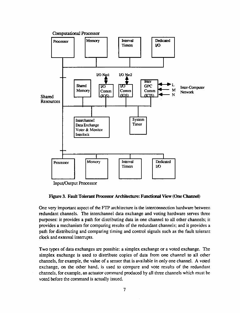
A functional view of one channel of an AIPS R P is shown in Figure 3. The CP and IOP are identical, conventional processor architectures. Interval timers are used for scheduling tasks and maintaining time-out limits on applications tasks (task watchdog timers). A hardware watchdog timer is provided to increase fault coverage and to cause a processor to fail-safe in case of hardware or software malfunctions. This timer resets the processor and disables all of its outputs, if it is not reset periodically. The watchdog timer is implemented independently of the basic processor timing circuitry. A monitor and interlock circuit in each channel provides the capability to disable the outputs of faulty processors. Any two correctly operating processors in a mplex FlT can disable the outputs of the third failed processor through this interlock mechanism. A processor that is failed active is thus prevented from transmitting erroneous data or commands on VO networks, IC networks, and local VO devices.
The CP and IOP share resources through a bus that can be accessed by either processor. These shared resources include memory; a system timeK the interchannel data exchange and voting circuits; and interfaces to one or more YO networks, memory mapped VO devices, and the IC network.
6
Computational Processor L
Processor Memory Interval Dedicated Timers m
L M N
+
Inter-Computer Network
InpuVOutput Processor
Figure 3. Fault Tderant Processw Architedure: Functional View (One Channel)
One very important aspect of the FIT architecture is the interconnection hardware between redundant channels. The interchannel data exchange and voting hardware serves three purposes: it provides a path for distributing data in one channel to all other channels; it provides a mechanism for comparing results of the redundant channels; and it provides a path for distributing and comparing timing and control signals such as the fault tolerant clock and external interrupts.
Two types of data exchanges are possible: a simplex exchange or a voted exchange. The simplex exchange is used to distribute copies of data from one channel to all other channels, for example, the value of a sensor that is available in only one channel. A voted exchange, on the other hand, is used to compare and vote results of the redundant channels, for example, an actuator command produced by all three channels which must be voted before the command is actually issued.
7

The interchannel data exchange and voting circuits appear on the shared bus as a set of registers which include the transmit register, the receive register, and error latches. Data is exchanged between redundant channels one word at a time by writing the word to the transmit register and then reading the result from the nxeive register. When an exchange is initiated, the transmitter in each channel sends to all channels either its own data (in the case of a voted exchange) or the data available from another channel (in the case of a simplex exchange). Each channel thus receives three copies of the data, which are voted on a bit- by-bit basis. The majority result, which will be the same in all channels even in the presence of an error, is placed in each processor's receive register. The type of exchange (voted or simplex) which will be performed is determined by the particular transmit register that is referenced when the exchange is initiated
Either type of exchange takes on the order of 5 microseconds in the engineering breadboard version of the AIPS FTP. The hardware is designed to lock out access to the receive register while the exchange is in progress; a processor which mes to read the receive register before the transaction has completed is suspended. As soon as the data becomes available, the processor is released and the register read cycle completes normally. The processor wait is thus transparent to the software.
The same software executes on a redundant FTP as on a simplex channel and application code is written as if it were to operate on a simplex computer. All redundant processors have identical software and execute identical instructions at exactly the same time. This feature of the architecture is carried out in the data exchange hardware and software as well. The data exchange hardware is designed such that all redundant processors execute identical instructions when exchanging data whether it is redundant data to be voted or simplex data being transmitted from one channel to others. Thus, for example, if a simplex exchange is to be made from channel A, all three channels write to their FROM-A register. While the contents of the FROM-A register are transmitted from A, voted, and deposited in the receive registers of all three processors, the contents of the FROM-A registers in channels B and C, which are meaningless, are ignored.
On a routine basis, the internally produced data that needs to be exchanged consists of error information and cross channel comparisons of results for fault detection. These operations can be easily confined to the program responsible for Fault Detection, Identification, and Reconfiguration (FDIR). Voting of the results of the redundant computational processors is performed in hardware by the inpudoutput processors and the system software responsible for the VO services. Therefore, the remaining pieces of the Operating System software and the applications programs need not be aware of the existence of the data exchange registers. The task scheduler and dispatcher, for example, can view the computational core as a single reliable processor.
Data from other processing sites is received by each IOP on the redundant IC buses,
8

hardware voted, and then deposited in their respective shared memories. Simplex source data such as that from VO devices is received by the IOP in one channel to which the VO device is physically connected. This data is then transmitted to the other two IOPs using the data exchange registers. The congruent data is then deposited in all three shared memories. Thus, the computational processor obtains all external data that has already been processed for errors and source congruency requirements by VO System Services executing on the VO processor.
The IOP and CP communicate through the shared memory. The IOP and CP have inde- pendent operating systems that cooperate to assure that the data from input devices is made available to the applications programs running in the CP in a timely and orderly fashion. Similarly, the two processors cooperate on the outgoing information so that the output devices receive commands at appropriate times. Hence the CP and IOP actions must be synchronized to some extent. To help achieve this synchronization in software, a hardware feature has been provided which enables one processor to interrupt the other. By Writing to a reserved address in shared memory the CP can interrupt the IOP and by writing to another reserved location the IOP can intempt the CP. Different meanings are assigned to this interrupt by leaving an event code in some other predefmed part of the shared memory, before the inter-processor interrupt is asserted.
For routine flow of infoxmation in both directions, the shared memory is used without interrupts but with suitable locking semaphores to pass consistent data sets. The interrupts can be used to synchronize this activity as well as to pass time critical data that must meet tight response time requirements. In order to assure data consistency, it is necessary that while one side is updating a block of data the other side does not access that block of data. This has been implemented using software semaphores. Hardware support for semaphores is provided in the form of the test and set instruction.
The architectural approach described above provides several significant operational benefits. The most important of these is the decoupling of the computational and input/output streams of transactions. The computational processor is unburdened from having to do UO transactions. To the CP, all UO appears memory mapped including not only UO devices but also all other computers in the system. That is, each sensor, actuator, switch, computer, etc., with which the FTP interfaces can be addressed simply by reading or writing words in the shared memory.
9

1.2 AIPSSystemsOftware
The AIPS system software, as well as the hardware, has been designed to provide a virtual machine architecture that hides hardware redundancy, hardware faults, multiplicity of resources, and distributed system characteristics from the applications programmer. Section 1.2.1 discusses the approach used for the AIPS system software design. Section 1.2.2 is a high level description of the system services that are provided for AIPS users.
1.2.1 AIPS Sofhare Design Approach
The approach used to design the AIPS system software is part of the overall AIPS system design methodology. An abbreviated form of this system design methodology is shown in Figwe 4. This methodology began with the application requirements and eventually led to a set of architectural specifications. The architecture was then partitioned into hardware and software functional requirements. This report documents the design approach used for Local System Services software, beginning with the functional requirements and proceeding through detailed specifications.
Hardware and software for the AIPS architecture is being designed and implemented in two phases. The frs t phase is the centralized AIPS configuration. The centralized AIPS architecture, as shown in Figure 5 , is configured as one triplex Fault Tolerant Processor (FTP), an Input/Output network and the interfaces between the FTP and the network, referred to as input/output sequencers (10s). The laboratory demonstration of the input/output network consists of 15 circuit-switched nodes which can be configured as multiple local VO networks connected to the triplex GPC. For example, the VO network may be configured as one 15-node network, as shown in Figure 5, or as three 5-node networks. The software building blocks that have been designed and implemented for the AIPS centralized architecture include local system services and UO system services. The following subsection 1.2.2 gives an overview of all the AIPS software building blocks. The remainder of the document, Sections 2 through 6, focuses on the functional design and detailed specification of the Local System Services.
10

Appiicrtion Requirements
Specifications
IC System Serv ices 0 System Hardware
Specifications
Local System Serv ices Serv ices
Figure 4. AIPS System Design Approach
11
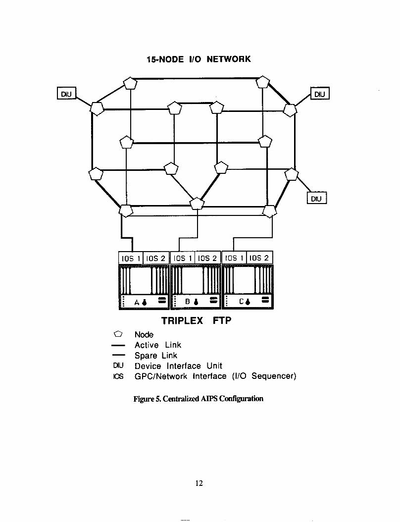
15-NODE I/O NETWORK
TRIPLEX FTP Node Active Link Spare Link Device interface Unit GPC/Network Interface (I/O Sequencer)
Figure 5. Centralized AIPS Configuration
12

1.2.2 AIPS System Software Overview
As shown in Figure 6, AIPS system software provides the following AIPS System Services: local system services, communication services, system management, and VO system services. The system software is being developed in Ada. System services are modular and partitioned naturally according to hardware building blocks. The distributed AIPS configuration includes all the services. Versions of the system software for specific applications can be created by deleting unused services from this superset. The System Manager functions reside on only one GPC, but all functions of the System Manager are not necessarily on the same GPC. The other system services ~IE replicated in each GPC. A brief description of each of the services follows.
Figure 6. Top Level View Of System Services
1.2.2.1 Local System Services
The local system services provided in each GPC are: GPC initialization, real-time operating system, local resource allocation, local GPC Fault Detection, Isolation, and Reconfiguration (FDIR), GPC status reporting, and local time management (see Figure 7).
13

FuNmoN LOCATION
I
TIME STATUS LOCAL SYSTEM STATUS +
Figure 7. Local System Services
The function of GPC initialization is to bring the GPC to a known and operational state from an unknown condition (cold start). GPC initialization synchronizes the CPs, synchronizes the IOPs and resets or initializes the GPC hardware and interfaces (interval timers, real time clock, interface sequencers, DUART, etc.) It makes the hardware state of the redundant channels congruent by alignment of memory and control registers. It then activates the system baseline software that is common to every GPC.
The AIPS real-time operating system supports task execution management, including scheduling according to priority, time and event occurrence, and is responsible for task dispatching, suspension and termination. It also supports memory management, software exception handling, and intertask communication between companion processors (IOP and CP). The AIPS operating system resides on every CP and IOP in the system. It uses the vendor-supplied Ada Run Time System (RTS), and includes additional features required for the AIPS real-time distributed operating system.
The GPC resource allocator coordinates and determines responsibility for any global or migratable functions from the system resource manager. It also monitors commands from the system resource manager to start or stop any function.
14
The GPC status reporter collects status information from the local functions, the local GPC FDIR, the IC system services and the I/O system services. It updates its local data base and disseminates this status information to the system manager.
GPC FDIR has the responsibility for detecting and isolating hardware faults in the CPs, IOPs, and shared hardware. It is responsible for synchronizing both groups of processors in the redundant channels of the FlT and fur disabling outputs of failed channel@) through interlock hardware. After synchronization, all CPs will be executing the same machine language instruction within a bounded skew, and all IOPs will be executing the same machine language instruction within a bounded skew. GPC FDIR logs all faults and reports status to the GPC status reporter. It is responsible for the CPU hardware exception handling and downmodinghpmoding hardware in response to configuration commands from the system manager. It is also responsible for transient hardware fault detection and for running low priority self tests to detect latent faults. This redundancy management function is transparent to the application programmer.
The local time manager works in cooperation with the system time manager to keep the local real time initialized and consistent with the universal time. It is also responsible for providing time services to all users.
Sections 2 through 6 describe the Local System Services functional requirements and design and detailed specifications. Each of these sections describes one of the Local System Services functions. Section 7 concludes with a summary of results and suggestions for future work in this area.
1.2.2.2 Inter-Computer System Services
The inter-computer system services provide two functions: (1) inter-computer user communication services, that is, communication between functions not located in the same GPC, and (2) inter-computer network management (Figure 8).
The IC user communication service provides local and distributed inter-function communication which is transparent to the application user. It provides synchronous and asynchronous communication, perfoms error detection and source congruency on inputs, and records and reports IC communication errors to IC network managers. Inter-computer communication can be done in either point to point or broadcast mode and is implemented in each GPC.
The IC network manager is responsible for the fault detection, isolation and reconfiguration of the network. The AIPS distributed configuration consists of three identical, independent IC network layers which operate in parallel to dynamically mask faults in a single layer and provide reliable communication. There is one network manager for each network layer. However, the three network layer managers do not need to reside in the same GPC. They are responsible for detecting and isolating hardware faults in IC nodes and links and for
15

reconfiguring their respective network layer around any failed elements. The network manager function is transparent to all application users of the network.
REALLoc mm0N FLAG ALLOCATION
1cmoRK m COMMAND GPC STATUS
LOCAL IC STATUS REPORTING
Figure 8 Inter-Computer System Services
1.2.2.3 System Manager
The system manager is a collection of system level services including the applications monitor, the system resource manager, the system fault detection, isolation and reconfiguration (FDIR), and the system time manager (Figure 9).
The applications monitor interfaces with the applications programs and the AIPS system operator. It accepts commands to migrate functions from one GPC to another, to display system status, to change the state of the system by requesting a hardware element state change, and to convey requests for desiEd hardware and software configurations to the system resource manager.
The system resource manager allocates migratable functions to GPCs. This involves the monitoring of the various triggers for function migration such as failure or repair of hardware components, mission phase or workload change, operator or crew requests and timed events. It reallocates functions in response to any of these events. It also designates managers for shared resources and sets up the task location data base in each GPC.
The system fault detection, isolation and reconfiguration (FDIR) is responsible for the collection of status from the inter-computer (IC) network managers, the 1/0 network managers, and the local GPC redundancy managers. It resolves conflicting local fault isolation decisions, isolates unresolved faults, correlates transient faults, and handles processing site failures.
16

GFC GPC STATUS CONFIG 1 CMND
\ - SYfXEimME \ I
CONFIG CMND m
Figure 9. System Manager
The system time manager, in conjunction with the local time manager on each GPC, has the job of maintaining a consistent time across all GPCs. The system time manager indicates to the local time manager when to set its value of time. It also sends a periodic signal to enable the local time manager to adjust its time to maintain consistency with an external time source such as the GPS Satellites or an internal source such as the real time clock in the GPC which hosts the system time manager software.
1.2.2.4 YO System Services
The VO system services provide efficient and reliable communication between the user and external devices (sensors and actuators). The VO system services software is also responsible for the fault detection, isolation and reconfiguration of the VO network hardware and GPC/network interface hardware (inpudoutput sequencers).
I/O system services is made up of three functional modules: VO user interface, UO communication management and the VO network manager (Figure lo).
17

YO
Figure 10. YO System Services
The VO user interface provides a user with readwrite access to VO devices or Device Interface Units (DIUs), such that the devices appear to be memory mapped. It also gives the user the ability to group YO transactions into chains and VO requests, and to schedule VO requests either as periodic tasks or on demand tasks. A detailed description of the VO user interface is provided in [3].
The UO communication manager provides the functions necessary to control the flow of data between a GPC and the various UO networks used by the GPC. It also performs source congruency and error detection on inputs, voting on all outputs, and reports communication errors to the I/O Network Manager. It is also responsible for the management of the VO request queues. A detailed description of the VO communication manager is provided in [3].
18

The ID Network Manager is responsible for detecting and isolating hardware faults in I/O nodes, links, and interfaces and for reconfiguring the network around any failed elements. The network manager function is transparent to all application users of the network. A detailed description of the UO Network Manager is provided in [4].
19

2.0 G P C ” U L E A T I 0 N
It is the responsibility of the GPC INIT module to bring the GPC to a known and operational state at startup and to initialize the system software tasks and the application procedures andor tasks.
2.1 G P C I n i t j a l i z a t i a n ~ Requirements and Mgn
The function of GPC initialization is to bring the GPC to a known and operational state. If the GPC has a redundancy level greater than a simplex, the initialization software module is responsible for controlling the transition from an unknown, uninitialized state of the FTP hardware to a state such that all available channels are operating in an instruction- synchronous manner. Furthermore, the module will insure that the channels operating in such a synchronous manner will have “aligned”, or “bit-for-bit identical”, states of all redundant hardware elements (e.g., RAM and interval timers). Once this instruction- synchronous, hardware-aligned status is established for the FTP, it will continue to operate in a synchronous mode until a fault forces a channel out of synch. (This statement assumes all external data to the FIT is made congruent across channels by the appropriate UO software.)
Upon reset, a processor will vector to the start-up entry point of the operating system. Standard initialization operations must be performed at this point:
Initialization of standard hardware such as interval timers, real time clock, and DUARTs
0 Exception vector initialization
Interrupt handler initializations
0 Software initialization (Ada “elaboration”, including initialization and activation of tasks)
0 Execution of power-on self tests
After the standard initialization functions are performed, the FIT specific initialization is performed. The redundant channels are synchronized to the instruction level. Since each channel has two processors, each processor is synchronized with the other processors of its type (Le., CPs or IOPs). In addition, its companion must be synchronized with other processors of the companion’s type, i.e., either both processors of a channel are good or they are both failed. Thus, processor activity within each channel must be coordinated before and during the synchronization process. The processors within each channel synchronize with one another to the extent that all of the intra-channel processors finish
PRECEDING PAGE BLANK NOT FILMED
21

their pre-synch initialization and signal their readiness to operate in synch with their corresponding inter-channel processors. After instruction-level synchronization, the hardware state of the redundant channels is made congruent by alignment of memory and control registers. The channel synchronization and alignment functions are performed within the SYNC software module which is described in Section 4.2.2.2.
After channel synchronization the power-on self tests are performed in order to check for any hardware faults in memory, error latches, voters, real-time clock and monitor interlock hardware. After the system is operational the self tests continue to run in background to check for any latent faults, but they are run in their entirety at system startup. (Execution of the self tests at power-on is optional in the laboratory engineering model.)
Next the operating system tasks are scheduled. These tasks include the redundancy management sequencer task, the GPC Status ReporterKRT display tasks, and the VO system services tasks. Finally, the application tasks are scheduled and the self test loop is entered. The self tests execute at the lowest priority when the system would otherwise be idle.
2.2 GPC Initialization Software Specifications
procesS Name: Main Program
Inputs: DUART, interval timers, real time clock Unsynchronized Processors, Channels Non Aligned Volatile memory, control registers Uninitialized Task Control Blocks, Tasks Stacks Uninitialized interrupt handlers, exception handlers Uninitialized IOS, ICIS Unscheduled Tasks
An operational FTP in a known synchronous state All Tasks scheduled.
Notes: This process calls the SYNC process, Section 4.2.2.2
It is the responsibility of the GPC Init function to bring the FI’P to an operational mode at startup and to initialize the application procedures and/or tasks. GPC Init resides on both the IOP and CP of each processing site. Since Ada requires that the process which initially executes be named ‘Main Program’, the GPC Init function is so named in the Ada source code. Figure 11 is a diagram of the control flow of the GPC Init function. First the
22
DUARTs, interval timers, real time clock and the interrupt and exception vectors are initialized. Then the elaboration of all system packages and tasks is completed. This includes initialization of every task control block and task stack area. Next the available channels of the FIT are synchronized and all volatile memory, control registers, interval timers, and real time clock are aligned in the synchronized channels. This is done by the SYNC process, Section 4.2.2.2, in both the CP and IOP processors.
Once the FTP is running synchronously, a complete iteration of the self tests is performed. These tests, which detect and identify faults in memory, error latches, voters, the real-time clock and the monitor interlock, are described in Section 4.2.1.3. The difference in the power-on self tests and the background self tests is that the power-on tests are not interrupted until an entire iteration has been completed.
Next the Local System Services sequencer task, the F D W i m e Manager, is scheduled. This task is responsible for the execution of the periodic Local System Service functions: Fast FDIR, Transient FDIR and the Local Time Manager. The F D W i m e Manager is a high priority, periodic task and presently executes every 40 milliseconds. The periodicity of this task is dependent on the particular application running on the GPC; it may be different for each GPC site. The FDIEUTime Manager and the three processes it controls are discussed in Sections 4.2.1, 4.2.2 and 6.1.1.2.3.
Finally, the GPC Status Reporter display tasks are scheduled. There are three tasks for CRT display and one task for Macintosh display. Like the main task, these tasks are of the lowest priority and are time-sliced with each other and the main program. The GPC Status Reporter/display tasks are described in Section 5.2.2. The time slice interval is equal to the period of the fastest periodic task in the system.
At this point all of the Local System Services tasks have been scheduled and the FI'P is in a known and operational state. I/O System Services tasks and any application tasks may now be scheduled and/or application procedures called.
The main program fmally enters the self test loop where it executes continually at the lowest priority the self tests in order to uncover latent faults. The self tests are described in Section 4.2.1.3. If needed, applications may call procedures within this loop also.
23

Figure 11. GPC INIT Contrd Flow Diagram
24

3.0 REALTIME0PERA'I"GSYSI'EM
The foundation of the system software for AIPS is a real-time, multi-tasking operating system providing mechanisms for task scheduling, inter-task communication, memory management, and intempt handling. The AIPS operating system consists of the vendor- supplied Ada Run Time System (RTS) along with those extensions needed to implement the functions given below. The extensions are written in Ada with time critical sections done in assembly language to reduce system overhead. The AIPS operating system resides on every IOP and CP.
3.1 Real Time Operating System F'unctional Requirements
The AIPS operating system provides the basic system services necessary to support the other application software tasks (see Figure 12). These services include:
1.
2.
3.
4.
Task execution management, including scheduling according to priority, time and event occurrence; dispatching (context switching); task suspension and termination. Memory management, including global data allocation, local data allocation/deallocation and shared data access routines (protected read and write). Intertask communication, including both synchronous and asynchronous (mailbox) communication. Software exception handling.
I
TASK "ERTASK EXECUnON MANAG- COMMUNICATIONS
MANAGEMENT
Figure 12. AIPS Real Time Operating System
25
3.1.1 TaskExecidhManagement
The basic execution unit is the Ada "task". The management of task execution includes scheduling according to priority, time and event occurrence, dispatching, task suspension and termination. A static priority is associated with each task. Task execution order is according to priority and proceeds in a run-until-blocked mode until one of the following conditions occurs:
1. task completion, 2. self suspension, 3. preemption by hardware interrupt, 4. explicit scheduling of higher priority task, or 5 . time slicing of equal priority task.
A task is capable of scheduling itself or other tasks according to time (one-shot or periodic) or upon the occurrence of a software defined event. The option also exists to bracket the region of a tasks periodicity by time or events; i.e. provide start/stop times or events.
The RTS requirements of Ada provide minimal user control of task scheduling with the Ada rendezvous and the "delay" statement. Scheduling by event is not an Ada requirement. So extensions to the Ada RTS are necessary in order for the task to schedule itself or another task cyclically, as the result of an event, at an absolute time, immediately, or to deschedule a task (remove all scheduling requirements).
AIPS requires two additional functions that are not provided by Ada RTS vendors: (1) preserving the data exchange receiver register for each task during a context switch, and (2) voting the program counter (PC) after every interrupt. Preserving the data exchange receiver register is necessary because a data exchange requires two instructions, a write to the transmitter followed by a read from the receiver, and an interrupt could occur after the write but before the read. When a task is suspended, therefore, the receiver value must be saved in the task control block; when a task is resumed, this value must be restored to the receiver. In the laboratory demonstration implementation, which uses a Motorola 68010 processor with an 8 MHz clock, restoring the receiver register takes approximately 5 ps.
Voting the PC after every interrupt is necessary because an interrupt could bring unsynchronized channels back into sync, thus masking the faulty condition. The state of each channel at the time of the interrupt can be determined by voting the PC; when a channel's PC is different from the majority value the operating system sets a flag for the FDIR task. This procedure ensures that a fault is detected as early as possible. In the laboratory demonstration implementation, which uses a Motorola 68010 processor with an 8 MHz clock, the PC check takes approximately 43 ps, of which 5 ps is used for the data exchange.
26
3.1.2 MemwyMaqpmnt
There are two types of memory in the FIT, local memory and shared memory. Local memory is memory on the private bus and can be accessed only by a single processor. Shared memory is memory on the shared bus and can be accessed by both processors in a channel.
Local memory is used for task execution. The operating system is responsible for allocating and deallocating all local memory space from heaps and stacks. The user must be able to specify the amount of local memory to be allocated for tasks and data objects. Also, routines are provided for the controlled access (protected read and writes) to data objects shared between multiple application tasks resident on the same processor.
Shared memory can be accessed by tasks resident on different processors and by several tasks resident on the same processor. Routines are provided for controlled access (protected read and writes) to data objects shared between multiple application tasks resident on different processors.
3.1.3 Intertask Communication
Local intertask communication is communication that takes place between tasks executing on the same processor. The operating system supports two methods of local inter-task communication: synchronous and asynchronous. Synchronous communication requires the communicating tasks to be at a specified synchronization point and is implemented in Ada by the "rendezvous". In local asynchronous inter-task communication, the commun- icating tasks are not required to be at a specified synchronization point; rather the communication is via data "mailboxes" using the local memory controlled access routines.
Remote inter-task communication is communication that takes place between tasks executing on different processors. The operating system supports two types of remote inter-task communication: remote task release and asynchronous "mailbox" communication. Remote task release means that a task running on one processor can start or release a task on the other processor. The remote inter-task mailbox communication is supported by using the shared memory controlled access routines.
3.1.4 sOf€ware Exceptions
Software exceptions not explicitly handled by the applications tasks are intercepted by the operating system and the task is purged.
27
3.2 Real Time Operating System !kftware Specifications
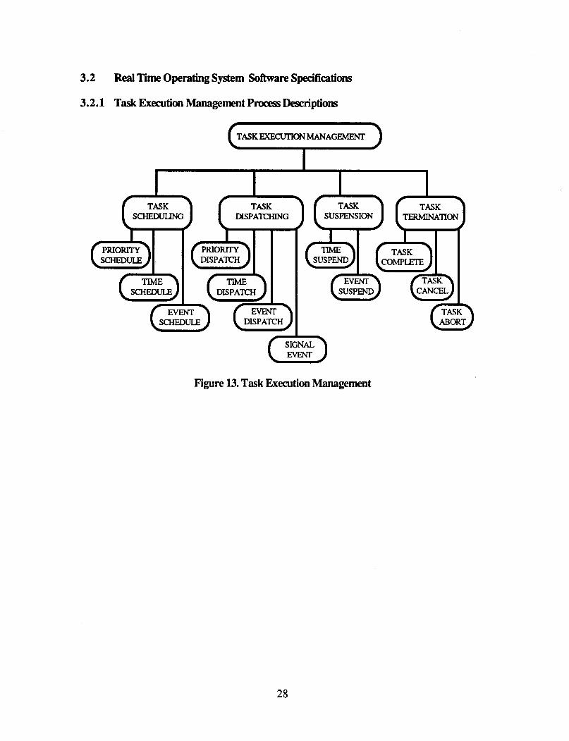
3.2.1 Task Execution Management procesS Descriptions
[TASKEXECUTIONMANAGEMENT 1
DISPA"ING SUSPENSION
Figure 13. Task Execution Management
28

3.2.1.1
Inputs: - 0
0
procesSName: PRIORTIY - SCHEDULE
GENERAL-TASK-ID
GENERAL-TASK-ID.TASK-NOT-WAITING
ImplementationRequirwnents: Initiation: Ondemand
procesS Description:
If task to be scheduled is not waiting at a scheduling synchronization point, the TASK-NOT-WAITING indicator is set and an immediate return to the caller is performed.
Otherwise, if priority of task to be scheduled (GENERAL-TASK-1D.PRIORITY) is greater than the priority of the active task (ACTrVE-TASK-ID.PRIORJTY), execution of the scheduled task is initiated via the PRIORITY-DISPATCH process; otherwise, the task being scheduled is placed on the ready queue according to its priority and a return to the active task is performed.
3.2.1.2
Inpk
e
e
0
e
htpuDi: 0
ProcessName: TIME - SCHEDULE
GENE=-TASK-ID GENERAL-TASK-ID.REPEnnON_TIME GENERAL-TASK-ID.COMPLETI0N-TIME GENERAL-TASK-ID.COMPLETION-EVENT INITIATION-TIME
None
Implementation Requirements: Initiation: - Ondemand
Process Description:
Task to be scheduled (GENERAL-TASK-ID) is placed on the time queue according to the specified start time (INITIATION-TIME).
If task is initial task on time queue, the time queue interval timer is updated.
29

3.2.1.3
Inputs: 0
0
0
0 - 0
GENERAL-TASK-ID G E N E R A L _ T A S K - I D . C o O N - ~ GENERAL-TASK-ID.COMPLETI0N-EVENT EVENT
None
ImplementationRequirements: Initiation: - Ondemand
procesS Description:
Task to be scheduled (GENERAL-TASK-ID) is placed on the event queue indicated by the specified event(EVENT).
3.2.1.4 Process Name: PRTORlTY - DESPATCH
Inputs: None
ImplementationRequirements: Initiation: - - active task suspension - active task termination
ready task priority > active task priority
Process Description:
If a task is active (ACTIVE-TASK-ID /=null), it is preempted and placed on the ready queue according to its priority (ACTIVE-TASK-1D.PRIORITY).
Execution of the highest priority task on the ready queue is initiated.
30
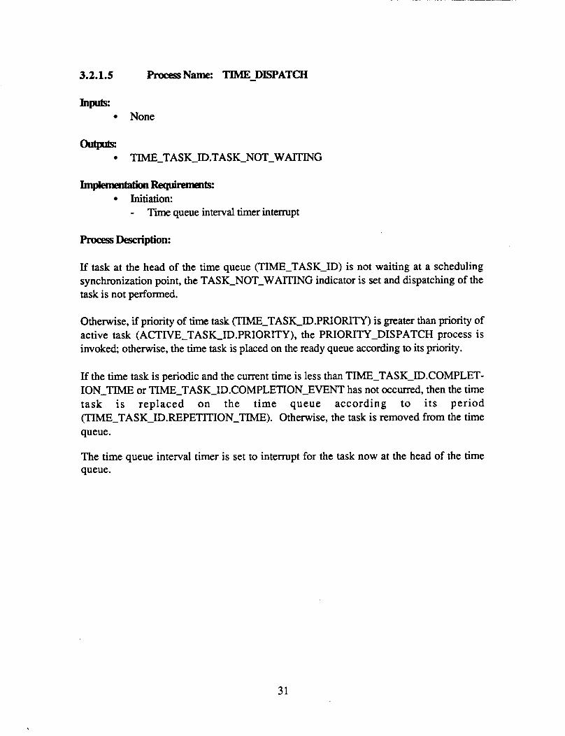
3.2.1.5 procesSName: TIME - DISPATCH
None
outplts: TIME-TASK-ID.TASK_"G
ImplementationReqUilp~~ Initiation: - Time queue interval timer interrupt
Process Description:
If task at the head of the time queue (TIMETASK-ID) is not waiting at a scheduling synchronization point, the TASK-NOT-WAITING indicator is set and dispatching of the task is not performed.
Otherwise, if priority of time task (TIME-TASK-ID.PRIORITY) is greater than priority of active task (ACTIVE-TASK-ID.PRIORITY), the PRIORITY-DISPATCH process is invoked, otherwise, the time task is placed on the ready queue according to its priority.
If the time task is periodic and the current time is less than TIMETASK-ID.COMPLET- ION-TIME or TIMETASK-1D.COMPLETXON-EVENT has not occurred, then the time task is replaced on the time queue according to its period (TIMETASK-1D.REPETITION-TIME). Otherwise, the task is removed from the time queue.
The time queue interval timer is set to interrupt for the task now at the head of the time queue.
31
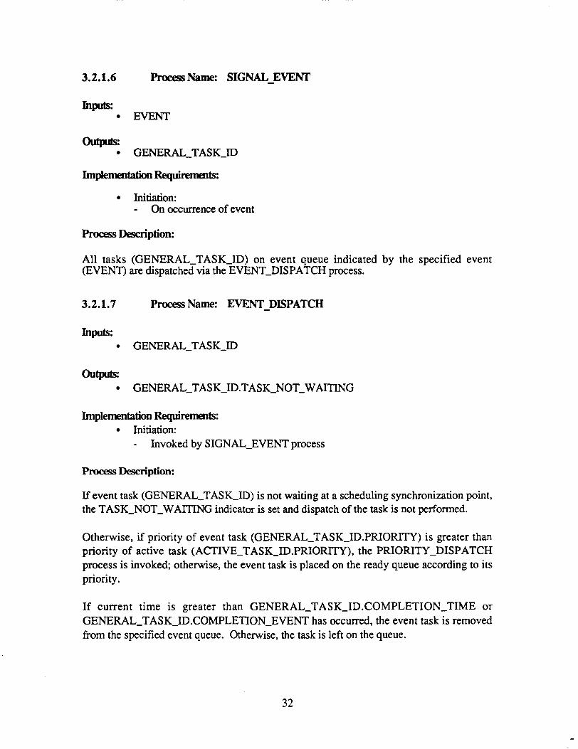
3.2.1.6 procesS Name: SIGNAL-EVENT
Inpub: EVENT
ol4J- GENERAL-TASK-ID
ImplementationRequirements:
Initiation: - On occurrence of event
procesf Description:
All tasks (GENERAL-TASKJD) on event queue indicated by the specified event (EVENT) are dispatched via the EVENT-DISPATCH process.
3.2.1.7 ProcesName: EVENT - DISPATCH
Inpub: GENERAL-TASK-ID
ouw GENERAL-TASK-1D.TASK-NOT-WAITING
Implementation Requirements: Initiation: - Invoked by SIGNAL-EVENT process
Process Description:
If event task (GENERAL-TASK-ID) is not waiting at a scheduling synchronization point, the TASK-NOT-WAITING indicator is set and dispatch of the task is not performed.
Otherwise, if priority of event task (GENERAL-TASK-1D.PRIORITY) is greater than priority of active task (ACTIVE-TASK-ID.PRIORITY), the PRIORITY-DISPATCH process is invoked; otherwise, the event task is placed on the ready queue according to its priority.
If current time is greater than GENERAL-TASK-1D.COMPLETION-TIME or GENERAL-TASK-ID.COMPLETION-EVENT has occurred, the event task is removed from the specified event queue. Otherwise, the task is left on the queue.
32

3.2.1.8 procesS Name: TIME-SUSPEND
u None
ImplemenGttionRequimmenk Initiation: - Ondemand This process is implemented in Ada by the "delay" statement.
Process Description:
The active task (ACTIVE-TASK-ID) is preempted and the TIME-SCHEDULE process is invoked to place task on the time queue for the specified delay time (DELAY-TIME).
Ready task execution is initiated by invoking the PRIORITY-DISPATCH process.
3.2.1.9 ProcessName: EVENT - SUSPEND
Inputs: EVENT
None
Implernenta!ion Requimmts: Initiation: - Ondemand
Procxm Description:
The active task (ACTIVE-TASK-ID) is preempted and the EVENT-SCHEDULE process is invoked to place task on the event queue indicated by the specified event (EVENT).
Ready task execution is initiated by invoking the PRIORITY-DISPATCH process.
33

3.2.1.10 procesS Name: TASK-CO-
Inputs: None
Implemen~Requirpments: Initiation: - Ondemand This process is implemented in Ada by the normal task completion processing of the run time system.
Process Description:
The active task (ACTIVE-TASK-ID) is deactivated. The ready task (READY-TASK-ID) is initiated by invoking the PRIORITY-DISPATCH process.
3.2.1.11 Process Name: TASK-CANCEL
Inputs: GENERAI-TASK-ID
Implementation Requirements: Initiation: - Ondemand
procesS Description:
The specified task (GENERAL-TASK-ID) is removed from the time queue and any applicable event queues. If the task has been preempted (Le. is on the run queue), it is allowed to run to completion.
34
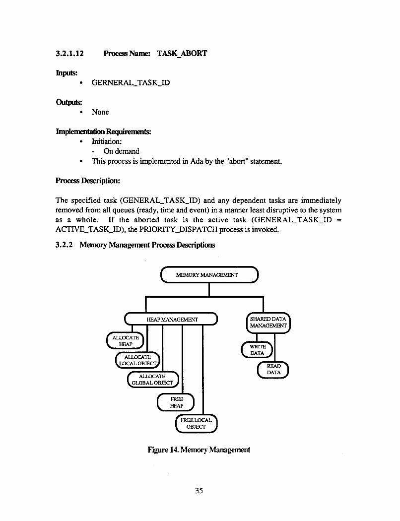
3.2.1.12 procesS Name: TASK-ABORT
Inputx GERNERAL-TASK-ID
hplementationRequi~lTbm$: Initiation: - Ondemand This process is implemented in Ada by the "abort" statement.
Process Description:
The specified task (GENERAL-TASK-ID) and any dependent tasks are immediately removed from all queues (ready, time and event) in a manner least disruptive to the system as a whole. If the aborted task is the active task (GENERAL-TASK-ID = ACTIVE-TASK-ID), the PRIORITY-DISPATCH process is invoked.
3.2.2 Memory Management Process Descriptions
MEMORYMANAGEMENT 1
HEAPMANAGE"
I
DATA
Figure 14. Memory Management
35

3.2.2.1
Inputs: 0
0
hm 0
GENERAI-TASK-ID GENEW-TASK-ID.HEAP_SIZE
GENERAL-TASK-ID.HEA€-BASE
hplementationRequiremts: Initiation: - Taskelaboration A STORAGE exception shall be raised if the requested amount of memory is not available. This process is implemented by the vendor supplied run time system at task elaboration.
procesS Description:
The specified amount (GENERAL-TASK-ID.HEAP-SIZE) of consecutive heap memory is allocated to the requesting task for local stack space and for allocating local data objects.
The base location address (GENERAL-TASK-ID.HEAP-BASE) of memory allocated is returned to the process user.
36
3.2.2.2
Inputs:
am 0
h.ocessName: ALLOCATJ3LocAL-ORn;'rrr
LOCAL-OBJECT-SIZE
LOCAL-OBJECT-LOCATION
ImplementationRequim& Initiation: - Ondemand A STORAGE exception shall be raised if the requested amount of memory is not available. This process is implemented in Ada by the "new" allocator.
Process Description:
The specified amount (LOCAL-OBJECT-SIZE) of the requesting task's local heap space is allocated for use by the requesting task as a data object.
The object location address (LOCAL-OBJECT-LOCATION) is returned to the process caller.
3.2.2.3 Process Name: ALLOCATl-GLOBAL - OBJECI'
Inputs: GLOBAL-OBJECT-SIZE
outputs: GLOBAL,-OBJECT-LoCATION
Implementation Requirements: Initiation: - Ondemand A STORAGE exception shall be raised if the requested amount of memory is not available.
Process Description:
The specified amount (GLOBAL-OBJECT-SIZE) of the global memory is allocated for use by all tasks as a data object.
,The object location address (GLOBAL-OBJECT-LOCATION) is returned to the process caller.
37

procesSName: FREE-HEAP
GENERAL-TASK-ID GENERAL-TASK-ID.HEAP-SIZE GENERAL-TASK-ID.HEAP-B ASE
None
Implementation Requirements: Initiation: - Task Completion
Process Description:
The specified amount (GENERAL-TASK-ID.HEAP-SIZE) of local heap memory (GENERAL-TASK-ID.HEAP-BASE) previously allocated to the indicated task (GENERAL-TASK-ID) is released.
3.2.2.5 Process Name: FREE-JBCAL-OBJECI'
Inputs: LOCAL-OBJECT-SIZE LOCAL-OBJECT_LOCATION
atputs: None
Implementation Requirementx Initiation: - Ondemand This process is implemented in Ada by the UNCHECKED-DEALLOCATION generic.
Process Description:
The specified amount (LOCAL-OBJECT-SIZE) of the requesting task's local heap space (LOCAL-OBJECr_LOCATION> previously allocated is released.
38
3.2.2.6 ProcessName: WRITE-DATA
Ill*: SI-IAREI-DATA ACTWE-TASK-ID.OU"-DATA
None
hplementationRequiremen~ Initiation: - Ondemand
procesS Description:
The following actions are performed when writing to a shared data area (local or global):
If the shared data area (SHARED-DATA.AREA) is locked (SHARED-DATA.LOCKED = true), the task is suspended (via process EVENT-SUSPEND) until shared data is unlocked (SHARED-DATA.LOCKED = false).
Lock data area (SHARED.DATA.LOCKED = true). Write data (ACI'IVE-TASK.OUT_DATA). Unlock data area (SHARED-DATA.LOCKED = false).
39

3.2.2.7 ProcessName: READ - DATA Inputs:
SHARED-DATA
u ACTIVE-TASK-ID.IN_DATA
ImplementatiOnRequire~uts: Initiation: - Ondemand
Process Description:
The following actions are performed when writing to a shared data area (local or global):
If the shared data area (SHARED-DATA.AREA) is locked (SHARED-DATA.LOCKED = true), the task is suspended (via process EVENT-SUSPEND) until shared data is unlocked (SHARED-DATA.LOCKED = false).
Lock data area (SHARED.DATA.LOCKED = true).
Read data (AcnVE-TASK.IN-DATA).
Unlock data area (SHARED-DATA.LOCKED = false).
40

3.2.3 Intertask Communication procesS Desaiptions
IN"ERTMK COMMUNICATION
Figure 15. Intertask Communication
3.2.3.1 procesS Name: SYNCHRONOUS-SEND
Inputs: RECEIVER-TASK-ID SENDER-TASK-ID.OUT-DATA
outpub: SENDER-TASK-ID.IN-DATA
Implementation Requirementx Initiation: - Ondemand A TASKING exception is raised if a receiver task acknowledgement is not received. This process is implemented in Ada by the "rendezvous" entry call.
Process Description:
The SYNCHRONOUS-SEND process includes the following actions during synchronous intertask communication:
Obtain data from sender task (SENDER-TASK-ID.0UT-DATA) and store for receiver task (RECEIVER-TA SK-ID.IN-D ATA) . Initiate communication event with the specified receiver task.
Suspend sender task (via the EVENT-SUSPEND process) until receiver task acknowledges communication event completion (via the SIGNAL-EVENT) process.
Obtain data from receiver task (RECEIVER-TASK-ID.OUT-DATA) and store for sender task (SENDER-TASK-ID.IN-DATA).
41
3.2.3.2 procesS Name: SYNCHRONOUS-RECEIVE
Inputs RECEIVER-TASK-ID.IN-DATA
u RECEIVER-TASK-ID.0UT-DATA
Implementafjon Requimnents Initiation: - Ondemand This process is implemented in Ada by the "rendezvous" accept statement,
Process Description:
The SYNCHRONOUS-RECEIVE process includes the following actions during synchronous intertask communication:
If a sender task has not initiated a communication event, the receiver task is suspended (via the EVENT-SUSPEND process) pending that event.
Obtain input data from sender task (RECEIVER-TASK-ID.IN-DATA).
Perform communication processing.
Store output data for sender task (RECEIVER-TASK-ID-OUT-DATA).
Acknowledge communication event completion via the SIGNAL-EVENT process.
42

3.2.4 Software Exception procesS Description
Figure 16. Software Exception
3.2.4.1 Process Name: RAISE-EXCEPTION
Inputs: GENEW-TASK-ID EXCEPTION-ID
Implemntation Requirements: Initiation: - Detection of software exception This process is implemented in Ada by the vendor supplied run time system
Process Description:
Upon detection of a software exception (EXCEPTION-ID), the exception Occurrence is recorded and the appropriate exception handler (GENERAL-TASK-1D.EXCEPTION-- HANDLER (EXCEPTION-ID) specified by the executing task is performed. If there is no specified exception handler, the task is purged.
43

4.0 GPC FAULT DETECI'ION, IDENTIFICATION AND RECONFIGURATION
The AIPS FTP uses hardware redundancy with fault detection and masking capabilities to provide fault tolerance. The design of that hardware is based on theoretical principles and is described in detail in Appendix A. The fault tolerance provided by the hardware is greatly enhanced by the Fault Detection, Identification and Reconfiguration (FDIR) functions which are part of the FTP local operating system. While the hardware alone in a triplex FTP could sustain one fault, the FDIR software allows it to sustain multiple successive faults and identifies the fault(s) for an operator, thus making the FTP much more robust and serviceable.
4.1 GPC Fault Detdon, Identification and Reconfiguration Functional Requirements and Design
GPC FDIR is a process which is part of the local operating system in each AIPS processing site. The primary purpose of GPC FDIR is to keep the GPC and its external devices functioning correctly in the presence of any number of hardware faults. To achieve this, FDIR has two main functions:
identifying a failed channel, Le., detecting a fault, isolating it to a single channel, masking the faulty channel's inputs, and disabling its outputs.
recovering a failed channel, Le., determining that the fault no longer exists, bringing the channel into line with the two synchronized channels, accepting the channel's inputs, and3enabling its outputs.
These functions must consume a minimum of the processing resources of the FTP under both fault and no-fault conditions. The tasks and procedures used by FDIR to implement these functions are summarized in Figures 12 and 13 and described in detail in the following sections.
A secondary purpose of FDIR is to report the status of the local GPC to the System Manager via the GPC Status Reporter. Therefore, faults and reconfiguration events are logged so that the GPC Status Reporter may transfer the information to the System Manager, which may be running on another GPC.
PRECEDlNG PAGE BLANK NOT flLMED
45
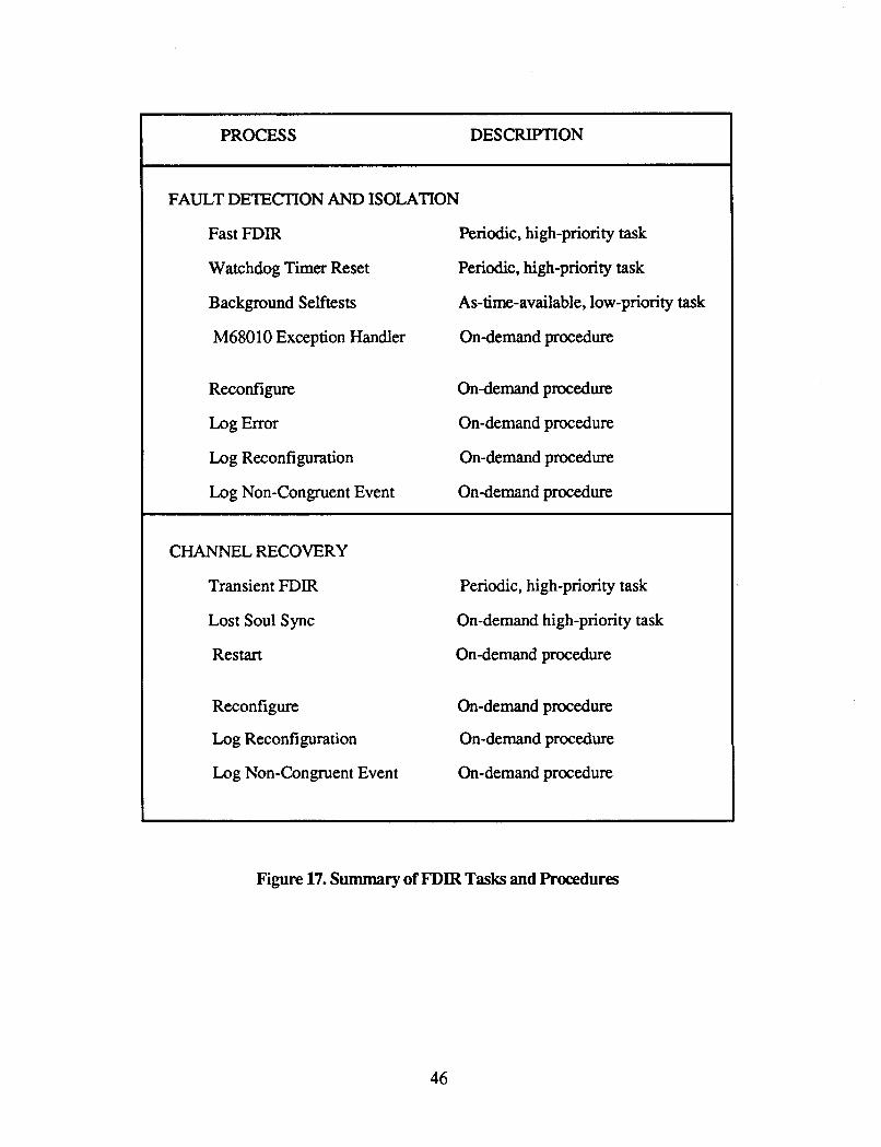
PROCESS DESCRIPTION ~~ ~~ ~
FAULT DETECI'ION AND ISOLATION
Fast FDIR Periodic, high-priority task
Watchdog Timer Reset Periodic, high-priority task
Background Selftests As-time-available, low-priority task
M68010 Exception Handler On-demand procedure
Reconfigure Ondemand procedure
Log Error On-demand procedure
Log Reconfiguration On-demand procedure
Log Non-Congruent Event On-demand procedure
CHANNEL RECOVERY
Transient FDIR Periodic, high-priority task
Lost Soul sync
Restart On-demand procedure
On-demand high-priority task
Reconfigure On-demand procedure
Log Reconfiguration Ondemand procedure
Log Non-Congruent Event On-demand procedure
Figure 17. Summary of FDIR Tasks and Procedures
46

Figure 18. FDIR Tasks and Procedures
47

4.1.1 FauItDetedm ' and Identification
Fault detection mechanisms are! implemented in both hardware and software, while the identification mechanisms are implemented solely in software. Instruction-level synch- ronization together with bit-for-bit comparison of redundant data makes it possible to isolate a fault to a single channel.
There are four main processes which detect and identify faults:
a periodic, high-priority task (Fast FDIR) which checks for failure of a companion, an unsynchronized channel, a failure in the data exchange hardware, and failure of a fault-tolerant clock;
a periodic, high-priority task (Watchdog Timer Reset) which taps the watchdog timer within the given time bounds sa that the timer does not overrun and cause a hardware reset;
a low-priority task (Background Selftests) which does tests to uncover latent faults in memory, voting circuitry and error latches, and the real-time clock;
a procedure for handling M68010 hardware exceptions such as an illegal instruction or addressing error.
After a channel is identified as being faulty, the GPC must be reconfigured so that the faulty channel does not affect GPC operation. The errors generated by the channel must be masked and its outputs must be stopped. This is done by a procedure (RECONFIGURE) which:
sets a software variable which identifies the channel as failed; disengages the monitor interlock so that outputs from the faulty channel are disabled. logs the fault and the reconfiguration for later examination by an operator.
4.1.1.1 FastFDIR
Fast FDIR is one of four tasks which detect and isolate errors. It is a high-priority task which runs every 40 ms. It checks for:
a failed companion processor an unsynchronized channel a failure detected but not reconfigured around by the selftests
48
a data exchange failure, i.e., either failure of the interstage or of any link in the data exchange hardware failure of a fault-tolerant clock. a missing companion processor
Error detection is done in the order given above. If any particular test uncovers a failure, the remaining tests are not done during that iteration of Fast FDIR. When an error is detected, the error is logged, the GPC is reconfigured to exclude the faulty channel, and the reconfiguration is logged.
Failed Co mpanion
When one of the two processors in a channel (CP or IOP) detects a failure, the companion processor is notified. The companion processors must fail their member in the same channel, even though it may be fault free. This ensures that the CPs and IOPs always have the same configuration.
Unsvnchronized Channel
An unsynchronized channel is detected by means of two tests: (1) the inconsistent PC check and (2) the presence test.
The inconsistent PC check is designed to handle the case where processors are out of sync but are brought back together by an interrupt, which thus masks the out of sync condition. Each time an interprocessor or timer interrupt occurs, a consensus value for the PC at the time of the interrupt is obtained by doing a FROM-ALL data exchange. Each channel then compares its own PC to the consensus value; a channel with a different value sets a flag which is subsequently checked by Fast. Checking the flag causes the inconsistent channel to diverge so that the two synchronized channels see it as missing when they do the presence test.
The presence test detects an unsynchronized channel by sending a unique pattern from each channel through the data exchange. If the result read from the data exchange receiver is not the expected pattern, the channel originating the exchange is judged not present and therefore out of sync.
Selftest Error
The background selftests attempt to detect latent errors, that is, errors which currently exist but have not yet caused data exchange errors or a channel to become unsynchronized. These tests are discussed fully in a later section. The selftest task does not reconfigure when it detects an error, however. It merely passes the pertinent information to the Fast FDIR task, which does the actual reconfiguration.
49

Data Exchange Failure
Failures in the data exchange are detected by analyzing the error latches set by the data exchange hardware. These latches are set during a data exchange if a miscornpare is detected during the voting of data received from the interstages. The latches identify the type of exchange and the channel at fault when the miscornpare occurred. A failure can be isolated either to (1) an interstage (including the transmitter-teinterstage link) , or (2) any link other than the transmitter-interstage link (i.e., transmitter-transmitter links and interstage-receiver links).
Fault-Tolerant Cloc k Failm
Failures in the fault-tolerant clocks are detected by analyzing the error latches set by the clock hardware. There are two sets of error latches: one which is set when the clock interstage detects faulty input from a clock element, and a second which is set when a clock element detects faulty input from a clock interstage. Failure of a fault-tolerant clock is merely logged, it does not cause the channel to be considered failed.
Missing Companion
A processor which has restarted because of a watchdog timer-caused reset or because of hardware or software exceptions needs to so notify its companion so that the companion may also restart. One way for such notification to occur is to have each processor periodically notify its companion that it is still running and at the same time check that its companion is still running. If a processor finds its companion missing, it assumes its companion has restarted and therefore does a software restart itself.
4.1.1.2 WatchdogTimer Reset
The second fault detection process is the Watchdog Timer Reset process. This process does not perform fault detection functions in quite the same way, however, as other processes in this category, Le., by responding to a specific fault. Rather, the failure of this task to execute at its scheduled period would indicate a critical fault in either hardware or software and would cause a hardware reset.
The watchdog timer is a hardware component whose purpose is to prevent infinite software loops or hardware faults from hanging up the system. After it has been started, the watchdog must be cleared periodically within a set time window; if it is not cleared within this window (i.e., either too early or too late) a hardware reset occurs. On the AIPS FTP this window is 60-120 milliseconds plus or minus 10%. The Watchdog Timer Reset process performs the function of clearing the watchdog timer.
50

4.1.1.3 BackgraundSelfTest
The third fault detection task is the Selftest task, a low-priority task which runs when the GPC has no other important work to do. Its job is to uncover latent faults, that is, faults which exist but which have not yet caused data exchange errors or desynchronization of a channel. This task does tests on four hardware elements:
Memory
Monitorinterlock Real-timeclock
Voter circuitry and error latches
The memory tests include the following:
PROM sum check. This test verifies that all channels have identical values in ROM by doing a sum check. RAM scrub. This test checks each memory location to ensure that the values are identical among the three channels. RAM pattern test. This test checks the functionality of each location. It tests each bit's ability to hold both a 1 and a 0 by writing specific patterns to each word. Shared memory scrub. This test checks each memory location in shared memory to ensure that the values are identical among the three channels.
Voter circuitry and error latches are tested by writing normal and faulty patterns of data to the voters. After these votes, both the resulting values and the error latches are checked to confirm that all errors were properly latched and corrected.
The monitor interlock is tested by reading the current value and ensuring that it is identical among the three channels.
The real-time clock is tested by reading the current value and ensuring that it is identical among the three channels.
4.1.1.4 HardwareExceptionHandler
The exception handler is the fourth fault detection process. It is invoked when there is a hardware exception such as an illegal instruction or an address error. The type of exception and relevant information such as the program counter and selected registers are logged in the non-congruent log. A presence test is done to determine if the exception was caused by a hardware error or a generic software error. If the results of the presence test show that a processor is alone, this implies a hardware error. If the presence test shows that a proces- sor is with others, this implies a generic software error. In either case, the exception and
51

the results of the presence tests are logged in the non-congruent log, and the processor(s) are restarted.
4.1.2 Channel Recovery
As mentioned earlier, the reliability of the FTP is greatly enhanced if channels previously diagnosed as faulty but currently operating without faults can be brought back into the FTP configuration. How a channel is recovered depends on the type of failure, Le., whether or not the fault has caused the channel to fall out of sync. A failure in the data exchange hardware does not desynchronize a channel, while other kinds of failures do. A GPC has recovered from a fault, therefore, when
the failed channel can be resynchronized, or the failed channel no longer shows errors in the data exchange hardware.
When a channel has been recovered, the GPC must be reconfigured so that the recovered channel participates in the GFT operation and another fault can be tolerated
There are three main processes involved in channel recovery. Transient FDIR distinguishes between transient and hard failures when a channel recovery is being attempted in order to balance competing system needs. Lost Soul Sync is responsible for resynchronizing an unsynchronized channel, i.e., synchronizing it to the instruction level and making its internal state the same as the duplex processors. Finally, the Restzirt process is invoked when a second fault or a common-mode failure occurs. These faults result in a fail-safe condition, which the AIPS FTP responds to with a system restart.
4.1.2.1 Transient FDIR
When recovering a failed channel, system resources are used most efficiently if a distinction is made between transient failures and hard failures. Transient failures are assumed to be caused by some temporary environmental condition (e.g., a power surge). By definition, they are expected to disappear with time. Hard failures, on the other hand, are caused by breakdowns of the FTP hardware that must be physically repaired.
The attempt to recover a failed channel could be made automatically (i.e., the software periodically tests the channel to determine its current state) or it could be made solely under operator direction (i.e., the operator enters a command indicating the channel has been repaired). The first method satisfies the need to recover the channel as quickly as possible while the second method satisfies the need to not waste system resources by repeatedly testing a channel with a hard failure. Transient FDIR strikes a balance between these two needs by initially assuming that any particular fault is transient (it has been observed that 50 to 80 percent of all faults in computer systems are transient) and automatically attempting a recovery. As time passes without the channel being recovered, it becomes
52

more likely that the fault is a hard failure rather than a transient, and Transient FDIR makes the recovery attempt less often. After a certain period it can reasonably be a s s u d that the failure is a hard failure and Transient FDIR either waits for an operator signal or tests the channel only at some infrequent interval such as its mean time to repair.
Additionally, it has been noted that hard failures tend to manifest themselves sporadically. A channel may be recovered according to the above criteria, but may immediately fail again. Transient FDIR attempts to prevent this situation by regarding a recovered channel as recovered only on a trial basis. If the channel passes its trial period without further errors, it is regarded as fully recovered and can be added back into the FI'P configuration. Intermittent failures which occur at infrequent intervals (i.e., after the mal period has passed) will not be handled by this scheme, however, but will be regarded as new faults.
This distinction between transient and hard failures thus defines the two functions of Transient FDIR:
It decides when it is appropriate to attempt to recover a failed channel. Once a channel is seen as fault-free, it monitors its health for a brief probation period before declaring it fully recovered.
Attempting Channel Recovery
The initial response to all detected faults is to mask the fault and disable all outputs from the faulty channel. Thereafter, the status of the failed channel is periodically "sampled" to determine if the fault is transient. Immediately after a failure, a recovery attempt is made and a sampling of the channels health is taken. If the attempt fails (Le., the unsynchronized channel cannot be found or the data exchange latches still show errors), the time between successive attempts is doubled, until Mean Time To Repair (MTTR) is reached. This time delay between successive recovery mes and the samplings of the status of a failed channel is a function of state variables representing the "health" of the channel. The "health" variable, in turn, is a function of the error history of the particular channel with many recent fault observations for the channel indicating "poor" health and declining fault observations representing "good" health. The time between recovery attempts is doubled following each status sampling which indicates the fault is still present. This sampling sequence is repeated until either the fault status changes to indicated the fault is no longer present or an upper threshold on the retry time is crossed at which point the fault is deemed "hard". From this point on recovery will be attempted only when another M'ITR period has passed or after an operator signals that the channel has been repaired.
Probation Monitoring
After a channel has been recovered, it must undergo a trial period before being declared fully recovered and functional. The length of this period is a function of the "health" of the
53

channel and depends on the number and type of faults. A channel with multiple faults in quick succession (i.e., the channel fails before it has passed its trial period) will have a longer trial period than if it only had a single fault. Faults that desynchronize a channel require a longer trial period than data exchange errors.
Additional Considerations
The work of Transient is complicated by several factors.
(1) A I P S is a bi-processor system. This has two ramifications.
(a) The CP and IOP must maintain identical configurations w A n the skew of one Fast cycle. Yet because of performance requirements, Transient runs only 25% as often as Fast. Identical configurations must be maintained because otherwise one side might see a failure as a single fault while the other side would see it as a double fault and go into fail- safe mode.
(b) When to execute the Channel Sync routine must be very closely coordinated between the CP and IOP so that neither side wastes time waiting at the handshake.
(2) 10s dual-ported memory and registers must be re-initialized after a recovery. Because of performance requirements and its low criticality, this process should not run uninterrupted and should not prevent Transient from making the other checks it must make during its periodic execution.
These factors led to the following design of the Transient FDIR process.
All decision-making in the task is done by the CP. The CP then communicates with the IOP via shared memory as to what to do, specifically whether to schedule the Lost Soul Sync task or the IOSS Restore task (see below).
The Channel Sync routine is run as part of a separate task (Lost Soul Sync) and is scheduled for an absolute time, which is calculated so that the IOP and CP spend minimal time waiting for each other. The Channel Sync routine sets a flag for Transient indicating whether or not it picked up the faulty channel.
The 10s re-initialization is run as a separate task. The CP tells the IOP when to start it; the IOP signals the CP when the task is complete. Provision is made for the case where a second error occurs before the 10s re-initialization is finished, since there is no way to stop a task in midstream.
After a channel has passed its probation period and reinitialized the IOS, it is permanently enabled by Fast FDIR rather than Transient. CP Transient, which
54

makes the decision to reenable, passes the necessary information to CP Fast, which in turn passes it to IOP Fast.
4.1.2.2 Lust Soul Sync
Lost Soul Sync is the process of attempting to resynchronize a previously failed channel (a "lost soul") and, if successful, bringing it to the same state as the two good channels. This process has two main steps:
resynchronizing the channel, Le., synchronizing it to the instruction level with the other two channels, and
aligning the channel, Le., making its volatile memory and registers the same as those of the other two channels. This ensures that after the code execution is synchronized, only a fault could cause a channel to lose synchronization, rather than, for example, a memory location that contained an incorrect value.
This task is an on-demand task scheduled by Transient FDIR when Transient deems it appropriate to attempt recovery of a failed channel. Because of the handshaking required between the CP and IOP, the task is scheduled to run at an absolute time. The following describes the two main steps of Lost Soul Sync.
The resynchronization function is performed in a loop where single-source exchanges are initiated with predetermined, constant data patterns being sourced. The exchanges executed in one iteration of the loop include one single-source exchange Erom each FIT channel. Divergent channels must be executing this loop at the same time in order to become synchronized. As a given channel performs the data exchanges within the sync loop, a comparison is made of the data received for a given exchange against the data expected for a successful exchange. A match indicates that the given channel is operating in synchronism with the channel at the source of the exchange; a mismatch indicates a lack of synchronism. Thus after every iteration a channel knows whether it is alone or synchronized and with whom. A channel remains in this loop as long as it is alone; channels which are together leave the loop either immediately (if they have become a triplex) or after a specified number of iterations (if they are a duplex).
Obviously, repetitive executions of the exact same loop of instructions by two unsynchronzed channels will never bring them to the point of synchronous operation. After each iteration, the two channels must delay their execution of the next iteration of the loop by different amounts of time in an attempt to phase shift into sync with one another. The length of the delay depends on the configuration of the channel(s), Le., each channel or combination of channels delays for a different amount of time. All other channels in this configuration will delay the same amount and thereby remain synchronized with each other.
55

Since each channel of the FTP may have multiple processors, a coordination of processor activity within each channel is required before and during the resynchronization process. Only one of the processors in each FIT channel executes the sync loop code described above. Before doing so, the processors within each channel handshake with one another to signal their readiness to operate together with their counterparts in other channels. This handshake is implemented using shared memory. The processors not executing the sync loop described above must suspend operation until the sync loop is exited and the result of the synch attempt is known. This suspension must be implemented such that on resumption of processor operation following a successful synch attempt, not only will the set of inter-channel processors which actually executed the synch code be in synch, but their companion (intra-channel) processors will also execute in synch with their inter- channel counterparts. This is accomplished by locking the shared bus; a reference to any component on the shared bus (in particular, shared memory) results in a suspended bus cycle which completes only when the shared bus is unlocked by the locking processor. Thus those processors not executing the actual synch code will be suspended on a shared memory access with the processors executing the synch code clearing the lock only after completion of the synch attempt. The result of the synch attempt is passed to the companion processor via shared memory.
It is imperative that once synchronous operation between channels is established, no conditional changes in program flow are made based upon data not congruent across channels. Immediately following a synch attempt in which an a lone channel is added to the configuration, all hardware elements must be made congruent (Le., 'aligned'). Any hardware element for which an incongruent state could cause a desynchronizing of channels must be aligned. Each processor within the channel must align its own local hardware resources. However, only one processor in a channel needs to align the shared resources within the channel (e.g., shared memory, real-time clock).
The same resynchronization and alignment processes are used for synchronizing three divergent channels at system startup.
56

4.1.2.3 System Restart
Certain faults which are detected may be of such a magnitude that they are unsustainable and may be recovered from only by restarting the system. Examples of such faults are a second fault detected by Fast FDIR and common-mode faults. The restart process accomplishes the system restart without requiring operator intervention.
4.1.3 Reconfiguration
The reconfiguration routine is called by the fault detection and identification tasks when a fault has been identified and by the recovery tasks when a channel has been repaired. During a reconfiguration a channel is either removed h m the configuration because it was found to be faulty, or added in because the fault no longer exists.
When a channel is identified as being faulty, the errors generated by that channel must be masked and its outputs must be stopped. This is done by (1) setting a software variable which identifies the channel as having failed, and (2) disengaging the monitor interlock so the channel's outputs are disabled.
When a channel has recovered from a failure, its inputs must be accepted and its outputs enabled. This is done by the reverse process, Le., (1) setting the software variable to say that the channel is now functional, and (2) engaging the monitor interlock so the channel's outputs are enabled.
When a channel has recovered from a failure, it is considered part of the configuration only by FDIR until its probation period has expired. This is done by setting a software variable to say that the channel is enabled on a trial basis.
4.1.4 Logging
Failures and reconfigurations are recorded in logs which may then be examined by a system operator or passed to the system FDIR manager. Certain failures and recovery actions are also entered in the non-congruent log, which contains unique information for each channel and is preserved by a software restart. The logs may be displayed by entering appropriate commands on a CRT or Macintosh computer.
57

4.2 GPC Fault Detection, Identification and Reconfiguration Software Specifications
4.2.1 Fault Detection and Identification Process Descriptions
f Fault Detection and
I I Background
Selftests Fast FDIR
Handler Watchdog
Timer Reset
Figure 19. Fault Detection and Identification Functions
58

4.2.1.1 FastFDI
I Process a ompanion Cornman
I CP-FDIR-AND-TIME IOPFDIRANDTIPvlE
I
(-) (-) Companion Present
Clock-Latches
Changes
Error Analysis Error Analysis
Figure 20. Fast FDI Processes
59

4.2.1.1.1 procesSName: CP-FDXRANDTIME IOP - FDIR - ANqTIME
Inputs: None
None
Description:
These tasks implement the periodic FDIR functions and the Time Manager function for the CP and IOP, respectively. Although Fast FDIR, Transient FDIR, and the Time Manager are tasks, conceptually speaking, they were not actually implemented as separate Ada tasks. Rather, only one task, a combined FDIR-AND-TIME task, was implemented. This task is scheduled to run at the frequency of the highest priority function, Fast FDIR. It executes Fast FDIR every time it is scheduled and then uses a counter to maintain the proper periodicity of the other functions, Le., Transient FDIR is executed only four times a second and the Time Manager only once. The motivation for the combined FDIR-AND-TIME task was to save the overhead time required for switching between separate tasks, especially since under no-fault conditions the time required for Transient FDIR is only a few microseconds. Interrupts are disabled while this task is executing.
4.2.1.1.2 ProcesName: FAST
Inpk Companion present flag from companion processor Enable command from companion (if IOP) or from Transient FDIR (if CP) Disable command from companion Disable command from selftest task
Companion present flag
Disable command to companion processor Enable command to companion (if CP)
This is the main procedure of the Fast FDIR process, and is called by the FDIR-AND-TIME task every 40111s. This procedure checks for the following faults:
failure of a companion processor, Le., a disable command from the companion a channel out of sync, i.e., either
60

- an inconsistent PC, which indicates to a lone channel that it was Out of sync at a timer or interprocessor intempt, or
- incorrect results from the presence test a fault detected but not reconfigured around by the selftests a data exchange error, i.e., either failure of the interstage or of any link in the data exchange hardware failure of a fault-tolerant clock absence of a companion processor, Le., the companion has ceased execution
In addition, the procedure checks for an enable command, which indicates that a previously failed channel has been recovered.
The above list indicates the priority of the tests. Once a fault is detected, the remaining tests are bypassed during that execution of the procedure, because they would fail anyway. For example, if a processor is out of sync, that would naturally cause the data exchange error latches to be set.
After an error is detected, it is logged. The GPC is reconfigured to exclude the faulty channel, and the reconfiguration is logged. A disable command is written in shared memory to notify the companion processors of the failure. For the appropriate types of failures (i.e., all errors except data exchange errors), the faulty channel now goes to the Channel Sync procedure . If a channel determines that it is alone and that the GPC has degraded from a duplex to a simplex (Le., a second fault has occurred), it goes to a FAIL-SAFE procedure.
An exception to this procedure occurs when a fault-tolerant clock failure is detected. This failure is not reconfigured around; it is merely logged.
The last step in the Fast FDIR procedure is to check for a Channel Enable command. The CP gets this command from Transient FDIR; if there is one it reconfigures, logs the reconfiguration and notifies the IOP by writing in shared memory. The IOP gets the Channel Enable command from the CP; if there is one it reconfigures and logs the reconfiguration.
Imdementation Notes
The shared bus is locked during any access to shared memory (Le., reading or writing the inter-processor commands). This is done to prevent these commands from simultaneous accesses. This implementation was selected over two alternative approaches:
1) using the shared readwrite services of the Ada runtime system, and 2) associating a lock variable with each shared memory command so that a specific
command could be locked rather than the shared bus.
61

The first alternative was rejected because the runtime system puts a task to sleep when a desired object is not available, and this is not an acceptable consequence for Fast FDIR. The second alternative was rejected because, while the amount of time that the shared bus was locked decreased, the amount of time to execute Fast FDIR increased. This thus became a tradeoff between taking time from the local processor and taking it from the companion processor. Locking the shared bus was then chosen because it is a simpler and m o ~ direct implementation.
Similar reasoning was used in the decision to use the shared data exchange, rather than the dedicated, for the presence test. Using the shared data exchange means the test can be very simple, but it required locking the shared bus. Using the dedicated data exchange does not require locking the shared bus but the test is more complex and takes longer. The shared exchange implementation was chosen because of its simplicity.
Finally, the shared bus is locked for the following sequence of tests:
Checking for a disable command from the companion Checking for an inconsistent PC Presence test - Doing the data exchanges - Writing disable command to companion if e m detected
This is done to ensure that when a processor falls out of sync, the error will be reported in a predictable way. Often a processor drops out of sync because its companion dropped out first. Locking the shared bus during the above sequence ensures that one side (and only one side) will report a presence failure while the other side will report a companion error.
4.2.1.1.3 Process Name: PROCES-COMPANION-COMMAND
Inputs Reconfig_cmd record
outplts: Entry in error log Entry in FAST-INFO array
Desaiption:
This procedure disables a channel when one set of processors (CP or IOP) has been notified that a companion has failed. The GPC is reconfigured to eliminate the faulty channel, and the error and the reconfiguration are logged. For errors other than data exchange errors, the companion to the failed processor drops out of sync at this point and goes to the Channel Sync procedure.
62
4.2.1.1.4 ProCeEsName: PRESENT
Inputs: None - Integer indicating channels in sync
This routine performs the presence test, Le., it checks for missing (unsynchronized) channels. It does this by sending a unique pattern from each channel through the data exchange. If the result read after a particular exchange is not the expected pattern, the channel originating the exchange is judged to be not present and therefore out of sync.
As mentioned in the Implementation Notes for the Fast process, the patterns exchanged are long words and are transmitted using the shared data exchange. When a word is exchanged using the dedicated exchange, the data exchange hardware is sufficiently slow such that any particular word will be in the receiver for more than one FTC cycle. This would allow a channel only slightly behind to see the expected word in the receiver and incorrectly conclude that it is in sync. Successive exchanges of long words, however, result in the long word being in the receiver for only one FTC cycle, so a tardy channel could not conclude that it was in sync.
Interrupts are disabled and the shared bus is locked before this routine is called.
4.2.1.1.5 Process Name: CHECK-COMPANION-PRESENT
Inputs Shared memory signal from companion
QJw Shared memory signal to companion
Description:
A processor which has reset because of the watchdog timer or because of hardware or software exceptions has no way to notify its companion of this fact. If one set of processors (i.e., CP or IOP) in all three channels reset in this way, they will never restart because they will all be waiting in the synchronization routine to handshake with their companions, who know nothing of their restart.
One solution to this problem is to have each processor periodically notify its companion that it is still running by writing a predefined value in shared memory. In addition to writing its own value, the processor determines if the companion is still executing by checking for the companion's value. The companion is allowed to m i s s one cycle before the processor assumes it has reset and does a reset itself.
63

4.2.1.1.6 Procesr Name: ANALYZE-DATA-LATc)rr;ls
Inputs: Data exchange error latches
olrtplts: None
This routine analyzes the e m r latches set by the data exchange hardware and identifies the particular element of the hardware which has failed (i.e., the specific interstage or link).
Each channel gets its own copy of the four error latches (one for each type of exchange) and combines them into one word. This word is then sent to the other two channels. All three channels do a software vote to get a consensus value of the three individual latches.
Only the CP checks for link and interstage failures, because these failures will be manifested in both processors. Both the CP and IOP check for "soft" errors (i.e., non- congruent data in a FROM-ALL exchange), since this type of error would be unique to the particular processor. Each type of failure causes the error latches to be set in a known way, which allows the error to be identified unambiguously. Figure 21 summarizes the types-of failures and the error latch settings for each type.
If only two channels are up, an error cannot be unambiguously identified. All that can be done in this case is to check for a second failure by ignoring any errors caused by the failed channel and then seeing if any other bits in the latches are set. To ignore errors caused by a failed channel X, three things must be masked:
any latches set during a FROM-X exchange, the bits representing channel X in the other types of exchanges. the exchanged copy of channel X's error latches.
A second failure results in a fail-safe condition in which the system restarts.
After a fault has been identified, the LOG-AND-RECONFIG subroutine is called to create the reconfiguration record and error log entry which will be used by the main Fast FDIR procedure.
64
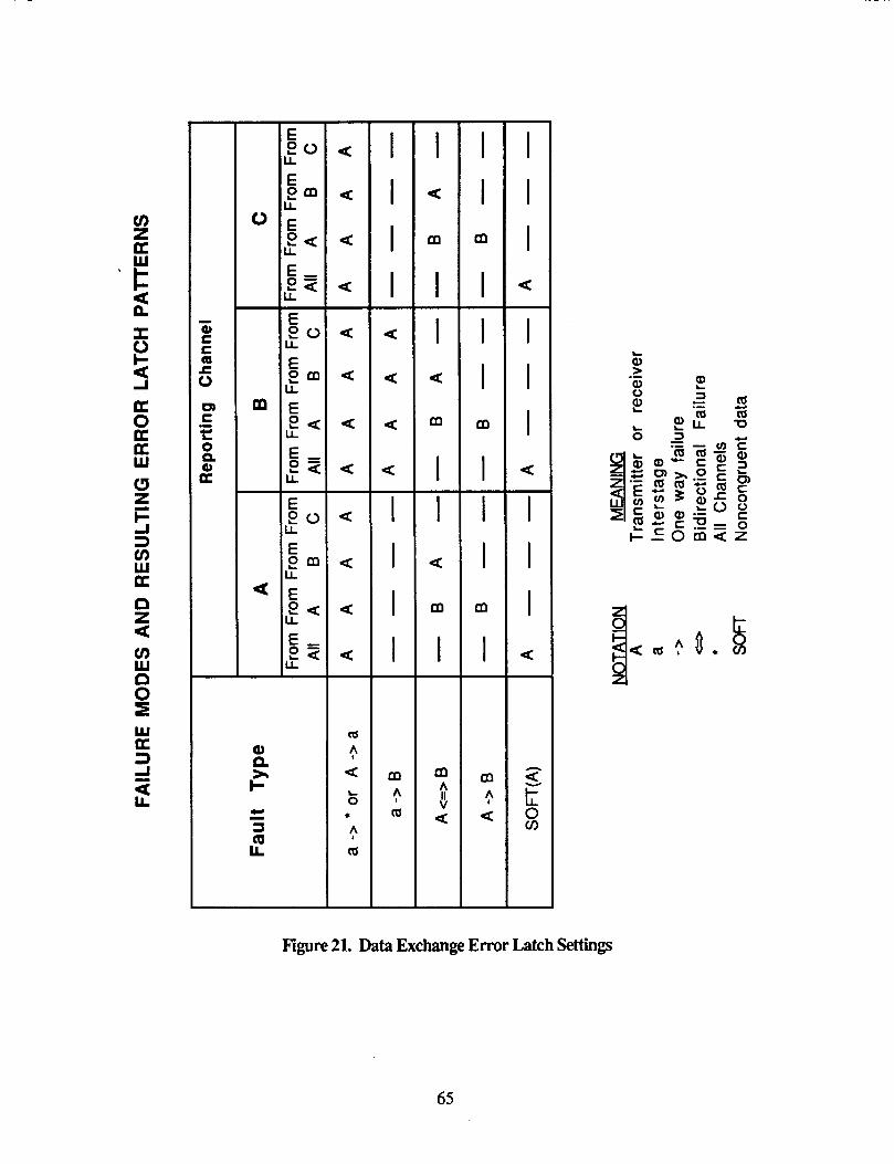
.jj E ,
9 0 LL
- I I I I - a
a
a
a - I I I I -
m ! m
- I
a
m
I I -
a
m
I I -
a
m
I -
m A II V a
- I I
I I I
I I I
I
m
-
m
-
m
-
m 9 a
-
- I I I
I I I
I I I
a -
a -
a
n
2 0 v)
m A I
m m U
c Q, 3
C 0 0 c 0 z
c
c
b
Eyre 21. Data Exchange Error Latch Settings
65
4.2.1.1.7 Process Name: ANALYZE - INTERSTAGE-FAILURE
Inputs: Voted value of e m latches from the three channels
o@ut= None
This routine checks for a hard interstage failure. When an interstage has failed, all channels will show an error in that channel for all types of exchanges. This is illustrated in Figure 22. A failure in the link between a channel's transmitter and its interstage will cause the error latches to be set in the same way. The failure of this link and the failure of an interstage are indistinguishable.
After an interstage failure has been identified, the LOG-AND-RECONFIG subroutine is called to create the reconfiguration record and error log entry which will be used by the main fast FDIR procedure.
66

4 W z z a v
4 W z z a z
4 W z z a -
LL
a LL
a LL
t t t
Figure 22 Latch Settings For Interstage Failure
67
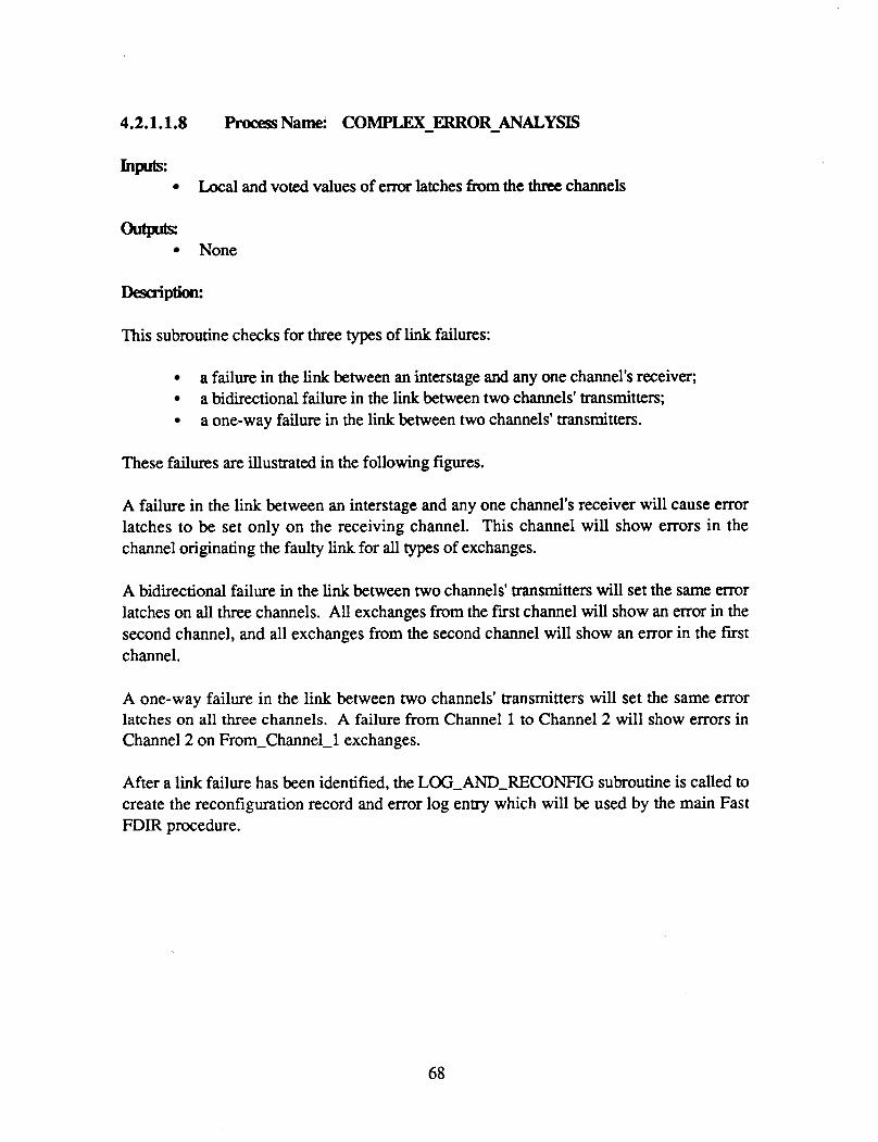
4.2.1.1.8 Process Name: COMPLEX-ERRORANALYSTS
Inputs Local and voted values of error latches from the three channels
w None
This subroutine checks for three types of link failures:
a failure in the link between an interstage and any one channel's receiver; a bidirectional failure in the link between two channels' transmitters; a one-way failure in the link between two channels' transmitters.
These failures are illustrated in the following figures.
A failure in the link between an interstage and any one channel's receiver will cause error latches to be set only on the receiving channel. This channel will show errors in the channel originating the faulty link for all types of exchanges.
A bidirectional failure in the link between two channels' transmitters will set the same error latches on all three channels. All exchanges from the first channel will show an error in the second channel, and all exchanges from the second channel will show an error in the first channel.
A one-way failure in the link between two channels' transmitters will set the same error latches on all three channels. A failure from Channel 1 to Channel 2 will show errors in Channel 2 on From-Channel-1 exchanges.
After a link failure has been identified, the LOG-AND-RECONFIG subroutine is called to create the reconfiguration record and error log entry which will be used by the main Fast FDIR procedure.
68

Figure 23. Latch Settings For Interstage - Receiver Link Failure
69

W K 3 J
L
- a m A II V
a
J W z z I 0 a
A u z z I 0 a
.I W z z I 0 a
Figure 24. Latch Setting For Bidirectional Transmitter - Transmitter Failure
70

t+ t+ t
J W z z I a
J W z z I a
0 0 0
e m
E LL
LL
2 z I LL
Figure 25. Latch Settings For Uni - Directional Transmitter - Transmitter Failure
71

4.2.1.1.9 Proms Name: SOFI'-ERFtOR_ANALYSIS
Inputs: Voted value of error latches from the three channels
u None
Desaiption:
This subroutine checks for a "soft" error, Le., non-congruent data sent during a FROM-ALL exchange. This type of error will set the same error latches on all three channels. The channel sending the non-congruent data will be identified as faulty on a FROM-ALL exchange (refer to the following figure).
After a "soft" error has been identified, the LOG-AWJECONFIG subroutine is called to create the reconfiguration record and error log entry which will be used by the main Fast FDIR routine.
72

I++++ t L I @ * I I -
4
a m 0 mJ mJ w W z z
m J W z z I a a
L I @ * I I -
a I
0 0 0
Figure 26. Latch Settings For ttSof€tt Failure
73

4.2.1.1.10 Process Name: ANALYZE-CIDCK-LATCHES
Inputs: Fault-tolerant clock e m r latches Fault-tolerant clock interstage error latches
u None
This routine analyzes the error latches set by the fault-tolerant clock hardware and identifies which clock element or clock interstage has failed.
Each channel gets its own copy of the two error latches (one from the interstage, one from the clock element) and combines them into one word. This word is then sent to the other two channels. All three channels do a software vote to get a consensus value of the three individual latches.
Each set of latches identifies errors about the other clock unit. Thus, the interstage latches identify faulty inputs from the clock elements. If Channel A's clock element fails, the interstage latches of all channels will show a fault in A. Conversely, the clock element latches identify faulty inputs from the interstage; if Channel A;'s interstage fails, the clock element latches of all channels will show a fault in A. These failures are illustrated in the following diagram,
This routine checks the current value of the latches against their previous value. If the value has changed, the routine determines whether a clock has failed or recovered, and makes an appropriate entry in the error log or the reconfiguration log.
74
W U 3 A
L I- z W I W J W Y O 0 O
2
J
m 0 J W z z a
J W z 2
I O
a
A W Z 2 a
a
i d 3 W
Figure 27. Latch Settings For Clock Element Failure
75

W K 3 J
LL
W (3
+ v) K W + Z
Y 0 0 J 0
z
a
I
W (3
I- v) pe W + z
a
I
a J W z z I 0 a
m A W z Z
I 0 a
0 J W z Z
I 0 a
I
Figure 28 Latch &ttings For Clock Interstage Failure
76

4.2.1.1.11 Fkcess Name: RECORI-CHANGES
Inputs:
Previous voted value Voted value of clock and clock interstage latches from the three channels
outprts: Entry in error log or reconfiguration log
This subroutine examines differences between the current and previous values of the FTC latches and determines that either a clock has failed or recovered. If a clock has failed, an entry is made in the error log; if a clock has recovered an entry is made in the reconfiguration log. Differences between the current and previous values of the FTC interstage latches are also examined and recorded.
77

4.2.1.2 WatchdogTimer Reset
The watchdog timer is a hardware component whose purpose is to prevent infinite software loops or hardware faults from hanging up the system. After it has been started, the watchdog must be cleared periodically within a set time window; if it is not cleared within this window (i.e., either too early or too late) a hardware reset occurs. On the AIPS FTP this window is 60-120 milliseconds plus or minus 10%.
Two methods are required to reset the watchdog: 1) a periodic task which regularly clears the watchdog during normal system operation, and 2) a special procedure which is used during Lost Soul Sync when interrupts are disabled and the periodic task cannot run. These procedures are described on the following pages.
Normal-Watchdog rn rn Timer 1 -Handler
Handle
Figure 29. Watchdog Timer Reset pnx3esses
78

4.2.1.2.1 procesS Name: NO~-WATCHDOG-RESET
Inputs: Channel-Sync-State indicator Atemate-Iteration indicator - Channel-Sync-State indicator Atemate-Iteration indicator
This routine is called by the highest priority task, the FDIR-AND-TIME task, to periodically clear the watchdog timer. This routine assumes that it is being called on every iteration of this task (i.e., every 40 ms) and that by clearing the timer on every other iteration it will be satisfying the timer requirements (refer to previous page). Clearing the watchdog in this way guarantees:
1) that timer interrupts are enabled, 2) that the runtime system is not in an infinite loop with interrupts off; 3) that the FDIR-AND-TIME task is being scheduled at its correct interval; 4) that the FDIR-AND-TIME task is not in an infinite loop; 5 ) that a processor which hangs waiting for a DTACK because it has referenced a
non-existent address will be reset.
Special provision has been made for clearing the watchdog timer while the Channel-Sync routine is running, because Channel-Sync cannot be interrupted and the amount of memory to be aligned when a lone channel is being picked up is so great that it cannot possibly be completed within 120 milliseconds. During Channel-Sync, one of the unused interval timers is used to periodically cause an interrupt, at which time the watchdog is cleared. After Channel-Sync is completed, the job of clearing the watchdog reverts to the periodic routine, Normal-WatchdoLReset. However, its alternate iteration test is now invalid; for example, it may be the alternate iteration but the watchdog may have been cleared only a few milliseconds ago while Channel-S ync was running. Thus, immediately after Channelsync has completed, this routine must use a time comparison to determine when it should clear the watchdog. After the watchdog has been reset once using this method, the alternate iteration method becomes appropriate again.
The alternate iteration method is the preferred method because this guarantees that the FDIR-AND-TIME task is being scheduled at its correct interval, whereas always using a time comparison to clear the watchdog would not guarantee this.
79

4.2.1.2.2 procesS Name: Tiirl-Handk Handle - Timerl-Rupt
Inputs: Channel-Sync-State indicator
OutPrDs: Time watchdog last reset Newvalueintimer
As mentioned in the process description for Normal-WatchdogReset, under normal conditions the watchdog timer can be cleared by a periodic task. Special provision must be made, however, for clearing the watchdog while the Channel-Sync routine is running, because Channel-Sync cannot be interrupted and the amount of memory to be aligned when a lone channel is being picked up is so great that it cannot possibly be completed within 120 milliseconds. During Channel-Sync, one of the unused interval timers is used to periodically cause an interrupt, at which time the watchdog is cleared.
These routines are invoked when the timer interrupt occurs. They clear the watchdog and set the timer to go off again. After Channel-Sync is complete, the job of clearing the watchdog reverts to the periodic procedure, and so an interrupt which occurs after Channel-Sync is finished is ignored and the timer is not reset.
Two routines are required here because the interrupt handler must conclude with an RTE instruction and must therefore be written in assembler, while the actual work of checking flags and clearing the watchdog is more conveniently done in Ada. Thus the Timerl-Handler routine is an outer shell which ends with an RTE instruction, while the Handle-Timerl-Rupt routine does the actual work required.
80

4.2.1.3 Background Sei-
Voter Test
B ackgmund (->
I
1 I
ShMem Scrub 6 (=) SM Word
1 S y stem-Timer (-)
Test Word with Pattern * Test Location
Figure 30. Background Self€& F’rocesses
81

4.2.1.3.1 procesS Name: BACKGROW-SE-
Inputs: None - None
This is the main procedure of the selftest process and is run as part of the main program (CP-MAIN-PROG or IOPMAIN-PROG). It calls appropriate procedures to run the following tests:
Data exchange voter test Data exchange e m r latch test ROM sum check RAM scrub Shared memory scrub Pattern test on offcard RAM Pattern test on oncard RAM System timer test
When an error is detected, the reconfiguration is not done immediately, but Fast FDIR is signaled that a reconfiguration is required and the necessary information is passed in a global variable. Further testing is then delayed until FAST has done the reconfiguration. Testing resumes from the point at which the error was detected.
This procedure is also executed at system startup when the entire suite of selftests is run without interruption before any other tasks are started. In the laboratory testing environment, this startup execution is optional and is controlled by a flag set by the operator in RAM.
82
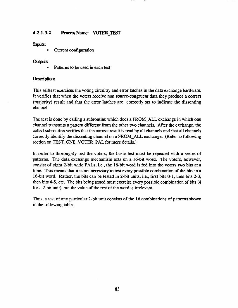
4.2.1.3.2 procesS Name: VO'IIBJ"
Inputs: Currentconfiguration
om- * Patterns to be used in each test
This selftest exercises the voting circuitry and error latches in the data exchange hardware. It verifies that when the voters receive non source-conjpent data they produce a correct (majority) result and that the error latches are correctly set to indicate the dissenting channel.
The test is done by calling a subroutine which does a FROM-ALL exchange in which one channel transmits a pattern different from the other two channels. After the exchange, the called subroutine verifies that the correct result is read by all channels and that all channels correctly identify the dissenting channel on a FROM-ALL exchange. (Refer to following section on TEST-ONE-VOTER-PAL for more details.)
In order to thoroughly test the voters, the basic test must be repeated with a series of patterns. The data exchange mechanism acts on a 16-bit word. The voters, however, consist of eight 2-bit wide PALS, i.e., the 16-bit word is fed into the voters two bits at a time. This means that it is not necessary to test every possible combination of the bits in a 16-bit word. Rather, the bits can be tested in 2-bit units, i.e., first bits 0-1, then bits 2-3, then bits 4-5, etc. The bits being tested must exercise every possible combination of bits (4 for a 2-bit unit), but the value of the rest of the word is irrelevant.
Thus, a test of any particular 2-bit unit consists of the 16 combinations of patterns shown in the following table.
83

Concurring Channels
00
01
10
11
Dissenting Channels
00 01 10 11
00 01 10 11
00 01 10 11
00 01 10 11
Figure 31. Test on a Two-Bit Unit
This test is repeated eight times, once for each 2-bit unit in the 16-bit word. Since there are three channels, the entire sequence described above is repeated three times, with each channel having a turn at being the dissenter. This routine generates the concurring and dissenting patterns which are used for each test.
The voter test is not started unless all three channels are in sync. If the TEST-ONE-VOTER-PAL subroutine reports that an error was detected, the voter test is discontinued and the next selftest starts execution.
84

4.2.1.3.3 ProcessName: l'"0NEVOTFlR-PAL
Inputs: Data exchange receiver values and error latches
WJ- Reconfigand record
Desaiption:
This routine does the actual data exchange required to test a particular PAL in the data exchange voters and analyzes the results. This exchange is a FROM-ALL exchange in which one channel transmits a pattern different from the other two channels. After the exchange the result read back by all channels should be the pattern sent by the two concurring channels, and all error latches should say that there was an error in the dissenting channel on a FROM-ALL exchange. If these conditions are not met, the test is considered to have failed.
For each FROM-ALL exchange done during the test, a "good" pattern (transmitted by the concumng channels) and a "bad" pattern (transmitted by the dissenting channel) are generated. The channels send out the different patterns by using their id as an index to an array containing the address of the desired pattern. Three different arrays, corresponding to who is the dissenting channel at the time, are used. Thus when A is the dissenter, addresses are chosen from a table where
table (1) = "bad-pattern table(2) = "good-pattern table (3) = "good-pattern
-- Ch A uses this address -- Ch B uses this address -- Ch C uses this address
Note: Care must be exercised when using channel id as an index to an array. The current definition of the channeljd type gives a value of 0 for A, 1 for B, and 2 for C. When Ada computes addresses within an array, it treats an index of 0 as a special case. Thus if the channels used their id as an index, channel A would drop out of sync. The solution is to convert the id from 0, 1, and 2 to 1 ,2 and 3, and then have a 0th entry in the table which is unused.
Venfving: the ExDected Results
To verify that each channel has obtained the correct result after the FROM-ALL exchange, each channel distributes its result to the other two. The result from each channel is then compared to the expected result; any unequal result indicates an error. After the exchange, the error latches are also analyzed to verify their correct setting. Each channel exchanges
85

its copy of the FROM-ALL error latch; these values are then compared to the expected latch value. Any unequal result indicates an error.
A channel may appear to fail this test when actually it has dropped out of sync but has not yet been detected as missing by Fast FDIR. Thus when a particular channel fails a voter test, it is not immediately identified as having a voter error. Instead, the routine does its own presence test using the dedicated data exchange to determine if the channel is still synchronized. If it is, a reconfiguration record and error log entry are created for fast FDIR; if the channel is not synchronized, the error is ignored. In either case, the voter test is then discontinued and the next selftest starts executing.
1) The test is not done if the FROM-ALL error latch is set already.
2) Interrupts must be disabled during the critical period which includes doing the FROM-ALL exchange, reading the result, and reading the FROM-ALL error latch.
86

4.2.1.3.4 procesS Name: L~4"lX-l'"
Inputs: Currentconfiguration
outplts: None
This selftest tests the error latches in the data exchange hardware for all types of exchanges. It verifies that when non source-congruent data is received by the voters, the error latches correctly indicate the channel at fault for the particular type of exchange.
The test is done by calling subroutines which cause two channels to do one type of exchange while the third channel does a different type. The subroutines verify that single and multiple errors are correctly latched. (Refer to following sections on GENERATE-DX-ERROR and GENERATI-MULTIPLE-ERROR.)
The latch test is not started unless all three channels are in sync. If either subroutine reports that an error was detected, the latch test is discontinued and the next selftest starts running.
87

4.2.1.3.5 Procesr Name: GENERATEDXERROR
Inputs: Data exchange error latches
Desaiption:
This routine verities that single data exchange errors are comt ly latched. This is done by causing two channels to do one type of exchange while the third channel does a different type. The results of the exchange do not need to verified, since this type of fault would be caught by the voter selftest. However, the error latches are checked to ensure that they correctly identify the dissenting channel on the particular type of exchange. If the error latches do not contain the expected value, the test is considered to have failed. By reading the error latches without clearing them, the routine guarantees that a particular fault will not be attributed to the wrong latch because of an address decoding problem.
The table on the following page shows the tests that are run and the expected results of each test.
In order for different channels to perform different exchanges without going out of sync, the test is table-driven, with each channel using its own id as an index into the table. (Refer to previous section on the voter test for cautions when using channel id as an index.) The table identifies the following for each test.
Address of the DX transmitter to be used by each channel in doing the exchange. Each channel accesses this address by using its own id as an index. The pattern to be exchanged. Each channel accesses this pattern by using its own id as an index. Expected setting of each channel's error latches for this test Expected setting of each channel's error latches for the multiple-error test (refer to following section)
After the exchange is done, the error latches from each channel are read and distributed. If the latches do not equal the value expected for each channel, the test is considered to have failed.
88
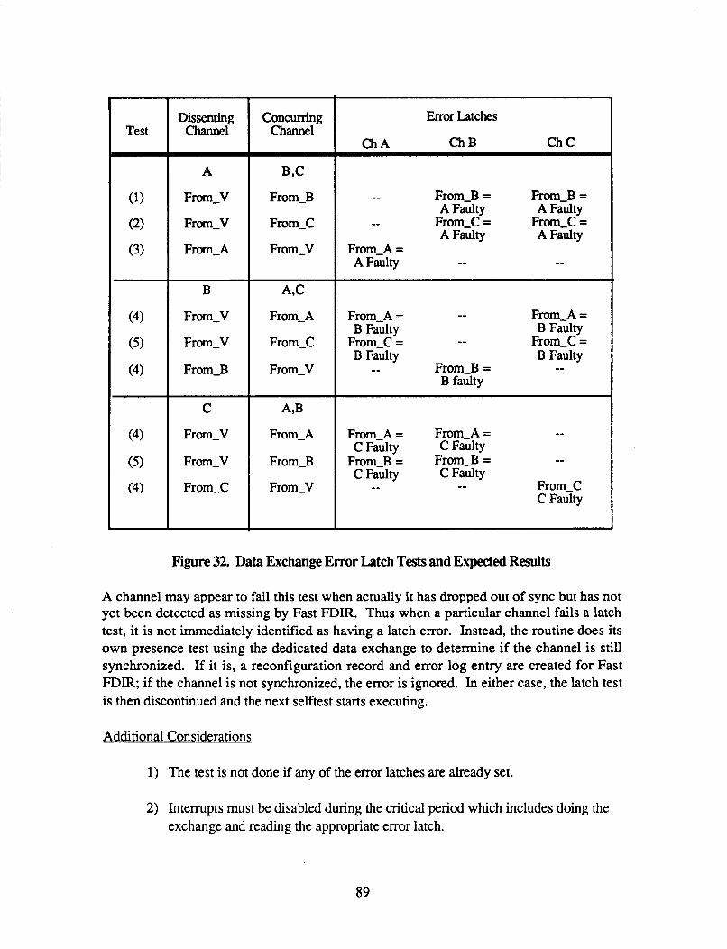
Dissenting Qlannel
A
From-V
From-V
From-A
B
From-V
From-V
From-B
C
From-V
From-V
From-C
Concurring Channel
B ,C
From-B
From-C
From-V
A,C
From-A
From-C
From-V
A,B
From-A
From-B
From-V
Emor Latches
ChB ChC
-- From-B = From-B = A Faulty A Faulty -- From-C = From-C = A Faulty A Faulty
From-A = A Faulty -- --
From-A = -- From-A = B Faulty B Faulty
From-C = -- From-C = B Faulty B Faulty -- From-B = --
B faulty
From-A = From-A = -- From-B = From-B = -- C Faulty C Faulty
C Faulty C Faulty -- -- From-C C Faulty
Figure 32. Data Exchange Error Latch Tests and Expected Results
A channel may appear to fail this test when actually it has dropped out of sync but has not yet been detected as missing by Fast FDIR. Thus when a particular channel fails a latch test, it is not immediately identified as having a latch error. Instead, the routine does its own presence test using the dedicated data exchange to determine if the channel is still synchronized. If it is, a reconfiguration record and error log entry are created for Fast FDIR; if the channel is not synchronized, the error is ignored. In either case, the latch test is then discontinued and the next selftest starts executing.
Additional Considerations
1) The test is not done if any of the error latches are already set.
2) Interrupts must be disabled during the critical period which includes doing the exchange and reading the appropriate error latch.
89

4.2.1.3.6 pro<.RssName: GENERATE - MULTIPLE - ERROR
Inpub: Data exchange error latches
Desaiption:
This routine verifies that multiple data exchange errors are correctly latched. This is done by repeatedly causing two channels to do one type of exchange while the third channel does a different type. This test is very similar to the single-error test described in the preceding section, and the reader should read this section before proceeding here. This test differs from the single-emr test only in that all errors for a particular channel are generated before the error latches are read. The errors are actually generated twice before the latches are read, so that the test verifies that both the same error and different errors can be correctly OR'ed into the latches.
4.2.1.3.7 ProcessName: ROM - SUM
Inputs: Starting and ending addresses of the memory to be summed
-m Reconfig_cmd record
This test verifies that all three channels have identical values in ROM. Due to the static nature of ROM, it is not necessary to check every individual location. Rather, each channel computes a checksum of all PROM locations and then sends its own sum to the other two channels. A consensus value is obtained by doing a software vote of the individual values; each individual channel's sum is then compared to the voted sum to identify any errors. Although there is a small probability that two errors will cancel each other and the sum check will not detect them, that probability is small enough to be neglected.
A channel may appear to fail this test when actually it has dropped out of sync but has not yet been detected as missing by Fast FDIR. Thus when a particular channel fails the ROM sum test, it is not immediately identified as having a ROM error. Instead this routine does its own presence test using the dedicated data exchange to determine if the channel is still synchronized. If it is, the ROM sum error is considered to be a legitimate error and a reconfiguration record and error log entry are created for Fast FDIR; otherwise the error is ignored .
90

4.2.1.3.8 Process Name: GET-SUM
Inputs: Starting and ending addresses of the memory to be summed
outplts: PROM checksum
This routine adds the contents of each 16-bit word in PROM and returns a 16-bit word containing the result.
4.2.1.3.9 Process Name: RAM-SCRUB
Inpk Starting and ending address of area to be tested
None
This procedure does a RAM scrub on the specified memory area. This ensures that the values in each location are congruent among the three channels. The subroutine SCRUB-WORD is called for each word in the area to be scrubbed (see following section).
91

4.2.1.3.10 procesS Name: SCRUB-WORD
Inputs: Address of 16-bit word to be scrubbed
u Reconfigand record
This procedure checks the specified memory location to ensure that the values are congruent, or identical, among the three channels. After the location has been read, each channel currently in the configuration sends its value to the other two channels. The value from each channel is then compared to a voted value.
A channel may appear to fail this test when actually it has dropped out of sync but has not yet been detected as missing by Fast FDIR. Thus when a particular channel fails the test, it is not immediately identified as having a RAM error. Instead, this routine does its own presence test using the dedicated data exchange to determine if the channel is still synchronized. If it is not, the error is ignored. If the channel is still synchronized, an error log entry identifying the location and value of the difference is created for fast FDIR and the test is repeated. If the word is still different, a voted value is written into the location and then read back. If the correct value is not read back, the failure is considered a hard failure and a reconfiguration record notifying Fast of the error is created.
There are some RAM locations whose contents may legitimately differ from channel to channel, e.g., the channel id and non-congruent data from external sources. Those variables which are known in advance as potentially different are kept in a non-congruent data area which is not scrubbed. But since not all the different RAM locations can be predicted (because, for example, of interrupts causing registers to be stored on the stack), at the present time only static variables are scrubbed.
92

4.2.1.3.11 procesS Name: SHMEM-SCRUB
Inputs: Starting and ending address of area to be tested - None
Dfsaiption:
This procedure scrubs the dual-ported memory shared by the IOP and CP to ensure that the values in each location are congruent among the three channels. The subroutine SCRUB-SM-WORD is called for each word in the area to be scrubbed (see following section). This procedure is only executed by the CP.
4.2.1.3.12 procesSName: SCRUB - - SM WORD
Inputs: Address of 16-bit word to be scrubbed
outplts: Reconfigand record
This procedure checks each memory location to ensure that the values are congruent, or identical, among the three channels. After a particular location has been read, each channel currently in the configuration sends its value to the other two channels. The value from each channel is then compared to a voted value.
A channel may appear to fail this test when actually it has dropped out of sync but has not yet been detected as missing by Fast FDIR. Thus when a particular channel fails the test, it is not immediately identified as having a RAM error. Instead, this routine does its own presence test using the dedicated data exchange to determine if the channel is still synchronized. If it is not, the error is ignored. If the channel is still synchronized, a reconfiguration record and error log entry identifying the location and value of the difference are created for later use by Fast FDIR, No attempt is made, as in the RAM scrub, to write a voted value and repeat the test because the IOP (this test is only done by the CP) could have written something into that location that the CP would be destroying.
93

4.2.1.3.13 procesS Name: RAM-PATI"
Inplls: Starting and ending addresses of area to be tested
outpltr None
Description:
This procedure tests the functionality of each word in the specified RAM area by writing a particular pattern to each word and reading it back. These patterns test the ability of each bit in the word to hold both 0 and 1 values. The subroutine TEST-WORD-WITH- P A T " is called for each word in the area to be tested (refer to following section).
4.2.1.3.14 Process Name: TEST - WORDWITHPATI"
Inputx Address of 16-bit word to be tested
Reconfigand record
DesaiptiOn:
This procedure tests the functionality of each word in RAM by writing a particular pattern to each word and reading it back. After a word has been written and read, each channel currently in the configuration sends its result from the test to the other two channels. The channels then verify that the test was passed on each individual channel.
Six different patterns, which represent the standard sequence of marching ones surrounded by zeros and marching zeros surrounded by ones, are written to each word. These patterns test each bit's ability to hold both a 0 and a 1 no matter what the setting of its neighbor bits.
A channel may appear to fail this test when actually it has dropped out of sync but has not yet been detected as missing by Fast FDIR. Thus when a particular channel fails the test, it is not immediately identified as having a RAM error. Instead, this routine does its own presence test using the dedicated data exchange to determine if the channel is still synchronized. If it is not, the error is ignored. Otherwise, it is assumed to be a legitimate RAM error and an error log entry is created for Fast FDIR. The test is then repeated, if the error occurs again, the routine assumes the error represents a hard failure and a reconfiguration record is created for Fast FDIR.
The actual reading and writing of the test pattern is done by calling an assembly language subroutine which saves the contents of the location in a register before testing it (refer to following section on TEST-LOCATION).

4.2.1.3.15 procesS Name: TESI-WCATION
Jnw
Pattern to be written Address of word to be tested
w- Value read after test pattern was wrimn
Desaiption:
This is an assembly language function which writes a specified pattern to a specified word in RAM, then reads it back and returns the value read to the d e r .
The c m n t value of the word to be tested is saved in a register before the test is started and restored when the test is finished. In the laboratory testing environment, where program code probably resides in RAM, the routine must take care not to write over its own instructions. The beginning and end of the critical section of code are identified with labels, and any locations within this area are not tested.
4.2.1.3.16 Process Name: SYSTEM-TIMER-I"
Inputs: Local and voted values of the system timer
u Recodiigcmd record
Description:
This test verifies that the system timers in all three channels have the same value. The channels first obtain a consensus value for the timer by doing a FROM-ALL exchange. Each channel currently in the configuration then sends its own timer value to the other channels and these individual values are compared to the voted value to identify any errors.
A channel may appear to fail this test when actually it has dropped out of sync but has not yet been detected as missing by Fast FDIR. Thus when a particular channel fails the test it is not immediately identified as having a timer error. Instead, the routine does its own presence test using the dedicated data exchange to determine if the channel is still synchronized. If it is, a reconfiguration record and error log entry are created for Fast FDIR; if the channel is not synchronized, the error is ignored.
95

4.2.1.3.17 procesS Name: GET-LA'I"-CONFIG
Inputs: Current configuration at runtime Startup configuration
outplts: Array identifying up channels
This routine converts the current configuration from a record of three booleans to an array of three booleans. The selftest routines can work more easily with the configuration represented as an array rather than a record. The input configuration record will either be the global configuration record maintained in the CONFIG package during normal system execution, or it will be the startup configuration record, which is a record local to the TEST package and which is used when the selftests are running uninterrupted at system startup.
4.2.1.3.18 Process Name: CREATI-=ONFIG
Inputs: Startup-selftest flag Faulty channel id and fault id
h- Reconfig-cmd record
This routine creates the reconfiguration record that is passed to Fast FDIR when a fault is detected. This record is not created, however, if a fault is detected while the selftests are running at system startup.
96

4.2.1.3.19 procesS Name: DELAYUNTILFAST
Inputs: Startllp-selftest flag
None
Description:
This subroutine is called after a fault has been detected and a reconfiguration record created for Fast FDIR. Its function is to suspend the selftest task until Fast FDIR has been able to reconfigure around the faulty channel. It does not want to do this, however, if the selftests are running at system startup, since at that time they are running with interrupts disabled and Fast will never execute.
4.2.1.3.20 Process Name: CHANNEL-PRESENT
Inputs: Channel id
oum Boolean indicating if specified channel is synchronized
Description:
This routine determined if the specified channel is synchronized with at least one other channel by doing a presence test using the dedicated data exchange registers. While a presence test using the shared data exchange would be simpler (refer to Section 4.2.1.1.4), it requires locking the shared bus, which is not an acceptable action for this task. Since any word that is transmitted using the dedicated exchange registers will remain in the exchange receiver for more than one FTC cycle, it is possible that a channel only slightly behind would see the expected word and incorrectly conclude that it was in sync. A valid presence test using the dedicated exchange must therefore do two rounds of exchanges: (1) each channel transmits a unique pattern and determines what other channels it sees, and (2) each channel transmits a unique pattern indicating who it saw. A software-voted value of who was seen is then obtained and compared to who the particular channel saw. If a majority vote could not be obtained or who the particular channel saw does not agree with the voted value, the particular channel itself is unsynchronized and returns FALSE. If the particular channel is synchronized, it compares who each individual channel saw with the voted value to determine if the specified channel is synchronized or not.
97
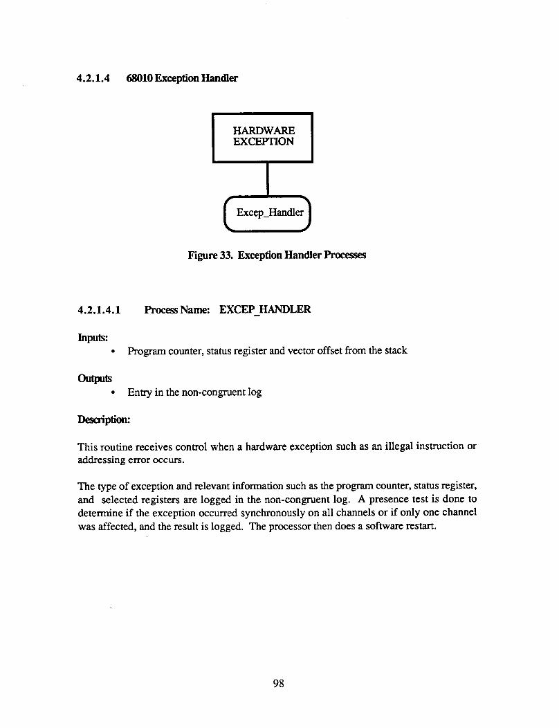
4.2.1.4 68010 Exception Handler
EXCEPTION T Excep-Handler 0
Figure 33. Exception Handler Processes
4.2.1.4.1 Process Name: EXCEP-HANDLER
Inputs: Program counter, status register and vector offset from the stack
outputs Entry in the non-congruent log
This routine receives control when a hardware exception such as an illegal instruction or addressing error occurs.
The type of exception and relevant information such as the program counter, status register, and selected registers are logged in the non-congruent log. A presence test is done to determine if the exception occurred synchronously on all channels or if only one channel was affected, and the result is logged. The processor then does a software restart.
98

4.2.2 Channel Recovery procesS Descriptions
I
c3 Recovery
I
Figure 34. Channel Recovery Functions
4.2.2.1 Transient FDIR
CP Transient 1 Decide-To-
Attempt-Recovery
IOP-FDIR-AND-TIME
IOP Transient
Figure 35. Transient FDIR Processes
99
4.2.2.1.1 procesSName: CP - TRANSIENT
hpuk
CHANNEL-STATUS array CHANNEL-ON-TRIAL array LOST-SOUL-STATUS boolean IOSS-RESTORE-CMD boolean
FASTJNFO array set by Fast FDIR
OUtP- CHANNEL-STATUS array Channel-enable-and for CP Fast
IOSS-restore-cmd boolean Sched-lost-soul command in shared memory
This is the main procedure of the TRANSIENT-FDIR process on the CP and is called by the CP-FDIR-AND-TIME task. It does all the decision making for both the CP and the IOP and notifies the IOP when either a resynchronization is to take place or the 10s must be reinitialized. It notifies CP Fast FDIR when a channel is to be permanently enabled. To support this decision making, this procedure maintains four variables about each channel:
FAIL-LEVEL: the amount of time the channel must operate correctly after it has recovered from a fault (i.e., the length of its probation). This variable is increment4 when a fault has been detected and decremented as the probation period passes.
RETRYBACKOFF: the amount of time between recovery attempts. This variable is set when a recovery is attempted and is doubled with each succeeding attempt until MT"R is reached.
RETRY-TIME: the amount of time remaining until another recovery attempt can be made (assuming the previous one failed). This variable is set with the RETRY-BACKOFF value when a recovery is attempted, if the recovery fails, it is decremented as time passes.
CHANNEL-ON-TRIAL: whether or not a channel is on probation. This variable is set when a channel is initially recovered, reset when the probation period is over and the IOP is signalled to start its IOSS restore task, and finally cleared when the IOP signals that the IOSS restore task is complete.
100

This procedure has work to do only when a channel is down. It makes the following sequence of tests; as soon as any condition is met, the current iteration of Transient is terminated.
Checks for a new error, i.e., one detected by Fast since the last iteration of Transient. If there has been a new error, the FAIL-LEVEL for the channel is updated and an attempt is made to mover the channel.
Checks if a channel is on probation. If so, it counts down the probation time by decrementing FAIL-LEVEL. When the probation time has expired, the IOP is notified to start the IOSS-RESTORE task and the CHANNEL-ON-TRIAL variable is set to WAITING-FOR-IOP.
Checks if the LOST-SOUL-SYNC task was previously scheduled, but has not run yet. If so, there is nothing to do.
Checks if the LOST-SOUL-SYNC task was previously scheduled and has picked up the failed channel. If so, it begins the channel's probation period by setting the CHANNEL-ON-= variable to yes.
Checks if there was a previously detected failure (i.e., CHANNEL-ON-TRIAL = NO) whose RETRY-TIME must be decremented. If so, RETRY-TIME is decremented; when it goes to zero, another attempt is made to recover the channel.
Checks if the channel has passed its probation period and is waiting for the IOP to finish the IOSS-RESTORE task. If the IOSS-RESTORE task is finished, Fast FDIR is notified that the channel an be permanently enabled.
The above checks must be made in the given order because of their priority. The check for a new error must be made first because this condition cancels all previously existing states, for example, a channel being on trial. Checking on the status of the LOST-SOUL-SYNC task must be done before checking for CHANNEL-ON-TRIAL = NO so that LOST-SOUL-SYNC does not get scheduled multiple times.
101

4.2.2.1.2
Inputs: 0
0
outplts:
0
0
FAST-INFO array Enrpr latches from Fast FDIR
Sched-lost-soul record in shared memory LOST-SOUL-STATUS boolean Scheduling of Lost-Soul-Sync task
This procedure is executed when a channel's RETRy_TIME ( the time between successive recovery attempts) has expired.
First the variables governing the recovery attempt (RETRY-BACKOFF and RETRY-TIME) are set for the next attempt. Then the procedure checks for the type of failure (synchronization or data exchange errors).
To recover an unsynchronized channel, the LOST-SOUL-SYNC task must be scheduled and a scheduling command written in shared memory for the IOP. The results of the LOST-SOUL-SYNC task will not be known until a subsequent iteration of the TRANSIENT task.
To recover from data exchange errors, the data exchange error latches are checked for the absence of errors. If no errors are detected, a command to temporarily enable the channel is sent to Fast FDIR and its probation period begins.
102

4.2.2.1.3
Inputs: e
e
e
e
u e
e
ProcessName: DECIDE - - To ATEMIT - RECOVERY
INITIALJtECOVERY-ATI'EMPT boolean RETRY-TIME CHANNEL-RECOVERY-MODE CHANNEL-REPAIRED
RETRY-TIME CHANNEL-REPAIRED
When a fault is first detected, it is regarded as a transient and recovery is attempted immediately. If the attempt fails, the time between successive attempts increases until MTI'R is reached. If the channel has not been recovered by this time, the fault is regarded as a hard failure. Action at this point depends on the user-specified recovery mode: either recovery is attempted every MTTR or recovery is attempted only when an operator indicates the channel is repaired. (The default in the laboratory testing environment is to attempt every M l T R ) .
103
4.2.2.1.4 ProcessName: IOP - TRANSIENT Inputs:
Sched-IOSS-restore command h m CP Sched-lost-soul command from CP
htprds: IOSS-RESTORE-SCHEDULED boolean
This is the main procedure of the TRANSIENT-FDIR process on the IOP and is called by the IOP-FDIR-AND-TIME task. It has work to do only when a channel is down. It checks for commands from the CP, which makes all the decisions of the TRANSIENT-FDIR process It can receive two commands from the CP:
to schedule the LOST-SOUL-SYNC task, which tries to pick up an unsynchronized channel, or to schedule the IOSS-RESTORE task, which re-initializes the 10s dual-ported memory and registers.
The command to schedule the LOST-SOUL-SYNC task specifies the absolute time at which the task should run. This is necessary so that neither the CP nor the IOP spend unnecessary time waiting in the LOST-SOUL-SYNC task to do their handshake.
The command to schedule the IOSS-RESTORE-TASK is cleared by the task itself to indicate that it is completed. This procedure uses the IOSS-RESTORE-SCHEDULED boolean in FDIR-GLOBALS to prevent itself from scheduling the task multiple times.
104
4.2.2.1.5 procesSName: FDIFt-GLOBALS
Inputs: None
outpds: None
This package contains types and variables shared by different tasks involved in the FDIR process.
Fast FDIR must pass several different pieces of infomation to Transient FDIR. This information is written by Fast, then read and cleared by Transient.
- -
The error latches read by the error latch analysis routine An array of flags, one for each channel, to indicate whether a channel's failure caused it to drop out of sync or not.
The Display task can accept a command from an operator that a failed channel has been repaired. It passes this infomation to Transient FDlR in an array of booleans, one for each channel.
CP Transient and IOP Transient communicate through commands in shared memory. The type for the Lost-Soul-Sync scheduling command is defined here.
IOSS Restore must indicate to IOP Transient when the IOSS Restore task is done. It does this by clearing a flag which IOP Transient has previously set.
105

4.2.2.2 Lust Soul Sync
CP-Handshake
~
[OP-Handshahk
u S y nc-Chan s
OST SOUL SYNC 'i I
I
("'1") Time
0 Align-Mem
a lign-Integer
Figure 36. Lost Soul Sync Processes
106

4.2.2.2.1 procesS Name: LOST-SOUL-SYNC
Inputs: None - None
The LOST-SOUL-SYNC task is scheduled when Transient FDIR has determined that an attempt should be made to pick up a channel that has become desynchronized. The task is scheduled to run at an absolute time and is descheduled after one iteration. It calls the CHAIWEL-SYNC routine which tries to pick up the lost channel.
4.2.2.2.2
Inputs: e
e
e
outputs: 0
0
procesS Name: CHANNEL-SYNC
Integer version of current configuration Reason for synching - initial or pickup Type of sync variable in global memory
Entry in reconfig log Type of sync variable in global memory
Description:
This is the main procedure of the LOST-SOUL-SYNC task. It is also the procedure used to synchronize channels at system startup. It is where channels who are together and channel(s) who are alone find each other. Its main steps are:
to synchronize the channels to the instruction level, and to align the channels' volatile memory and registers, i.e., make them identical amongst the synchronized channels.
107

Channel CP 4
I Attempt to Sync with other Channels
Two or more Together
Concur on type of sync
Sinal IOP
some Disagree
Wait For Signal From IOP
All Agree
Align memory & Registers
0 I 1 Align memory & Registers I I I
0
I Wait For Signal From IOP I+ - - I I
1 Log 8 Reconfigure I
Sync Flow
S H A R E D
M E M 0 R Y
IOP
Get consensus of CP 8 IOP I type of sync, 1 I Some DBagree
Sinal CP I
All Agree
_ - _ _ _ _
-~
Align memory & Registers
Signal CP
#N
Figure 37. Channel Sync Flow Diagram
108
To be in sync, a processor must be synchronized to the instruction level with other processors of its type (Le., CPs or IOPs). In addition, its companion must be synchronized with other processors of the companion's type, i.e., either both pmessors in a channel are good or they are both failed. The steps in the synchronization process and the interaction between CP and IOP are summarized below and shown in the following
Initial Handshake CPs Sync CPs Concur on Type of Sync CPs Signal IOPs IOPs Concur on Type of Sync IOPs Determine Consensus of CP and IOP Types of Sync IOPs Signal CPs CPs Align CPs Signal IOPs IOPs Align IOPs Signal CPs CPs Reconfigure and Log
Initial Handshake
The purpose of the initial handshake is to coordinate the synchronization of the CPs with that of the IOPs, since a processor cannot be considered synchronized unless its companion is also synchronized. This handshake ensures that both sides are in the Channel Sync routine before the attempt to sync is made. It also means that only one side (the CPs were chosen arbitrarily) needs to sync using the data exchange hardware. As explained in more detail in the process descriptions for CP-HANDSHAKE and IOP-HANDSHAKE, the other side (the IOPs) will automatically sync while waiting for their companions.
CPs Svnc
The CP locks the shared bus and makes a fixed number of attempts to synchronize with another channel(s) by doing data exchanges. As Iong as a CP is alone, it repeats this step.
CPs Concur on TvDe of Svnc
This step and the next four steps concern the CP and IOP agreeing on what type of sync they are doing. This agreement is required in order for the system to recover from some catastrophic condition, such as a second failure or hardware or software common-mode fault, by automatically restarting. These catastrophic conditions could result in channels 'going to the Channel Sync routine in different states, which would make it impossible for
109

them to be aligned. Therefore we must check why a channel is in Channel Sync and ensure that at least two channels arrive there in the same state.
There are four possible types of sync:
POWER-ON - an operator has restarted the system SOlT-RESTART - the software has restarted the system RECOVERY-CHANSTOGETHER - two synchronized channels are trying to pick up a lone channel RECOVERY-LONE-CHAN - a lone channel is trying to be picked up
A consensus value for the type of sync is arrived at by the standard method of bit-for-bit voting. If there is no majority, there will be no consensus, with one exception: a vote of POWER-ON and SOlT-RESTART results in a consensus value of SOlT-RESTART. This is because POWER-ON and SOFT-RESTART produce identical states in the processor; their only difference is that SOFT-RESTART preserves the existing non- congruent logs. The action taken when there is no consensus depends on the particular situation; this is discussed in more detail below.
The first step in arriving at a consensus value for type of sync is for the CPs to agree among themselves. After two or more CPs have synchronized, they all exchange their type of sync and obtain a voted value. If there is no consensus or if the majority are lone processors trying to be picked up, they have different states and cannot be aligned. They must restart in order to achieve identical states.
CPs Signal IOPs
After the CPs examine their type of sync, they notify the IOPs by setting the TOIOP variable in shared memory. They can set it to two possible values:
0 6 - The CPs could not achieve a consensus and/or had to restart. 7 - The CPs did achieve a consensus, The consensus value is written in 0
the TYPE-OF-SYNC variable in shared memory.
The CPs now wait for a return signal from the IOPs.
IOPs Concur on Type of Svnc
The IOPs reach a consensus on their type of sync in the same way as the CPs. They all exchange their type of sync and obtain a voted value. If there is no consensus or if the majority are lone channels trying to be picked up, they must restart so that they can achieve identical states.
110

If the IOPs did not have to restart, they now compare their voted type of sync to the CPs' type from shared memory. There are two possible results.
A consensus is reached. This will happen either because the two types are the same or because one is a Power-On and one is a Soft-Restart.
No consensus is reached. This will be the case when one side has started over (either a power-on start or a software restart), but the other side has not. In this situation, the side which did not restart must now do so. One side cannot continue from where it previously left off when the other side is starting afresh.
IOPs Signal CPs
After the IOPs examine their types of sync and the CPs' type of sync, they notify the CPs by setting the TOIOP variable in shared memory. They can set three possible values:
8 - The CPs must do a restart. The IOPs will wait for them at the Initial
9 - The IOPs must do a restart. The CPs should wait for them at the Initial
10 - A consensus value has been reached. It is written back into the
Handshake.
Handshake.
TYPE-OF-SYNC variable in shared memory. Both sides now use the consensus value as their type of sync.
The IOPs now start Interval Timer 1, which is used to reset the watchdog timer during the resynchronization process and wait for a signal from the CPs as to whether they need to align.
CPs Align
Having agreed on a type of sync, the CPs now check to see if they have picked up any new channel(s). If they have, they start Interval Timer 1, they then align their volatile memory and registers. These include:
intervaltimers RAM (oncard and offcard) testport memory oncard discretes shared discretes LMN data exchange control register
111

Finally the data exchange error latches and fault-tolerant clock error latches are cleared.
CPs Signal IOPs
The CPs notify the IOPs of the results of the above step by semng the TOIOP variable in shared memory. They can set it to two possible values:
2 - The CPs have picked up a channel and aligned. The IOPs must align also.
3 - The CPs did not pick up anyone new. The IOPs do not need to align.
IOPs Aliyn
If the CPs picked up a new channel, the IOPs must now align their volatile memory and registers. These are the same as on the CP side, with two additions:
sharedmemory system timer
Finally, the data exchange error latches and fault-tolerant clock error latches are cleared.
lops Notifv CPs
Whether or not the IOPs needed to align, they clear the TOIOP variable to signal the CP that they are done.
CPS Log: and Reconfirrure
Finally the CPs reconfigure and log the reconfiguration. This step is done here because the system timer is initializedaligned by the IOPs; a meaningful time is not available until this point.
112

4.2.2.2.3 procesS Name: CP-HANDSHAKE IOP-JIANDSHAKE
TOIOP variable in shared memory
u TOIOP variable in shared memory
These two routines execute the handshake between the CP and IOP which is required before an attempt to synchronize multiple channels is made.
The basic sequence of the handshake is for the CP to write some value in the TOIOP variable in shared memory and for the IOP to clear it. After the IOP has cleared it, the CP attempts to sync using the data exchange hardware, first locking the shared bus. When they have successfully synchronized, the CPs write another value in the TOIOP variable and unlock the shared bus. Meanwhile, the IOP, having cleared TOIOP, is waiting for the variable to change to some other value. The IOPs will automatically synchronize here because, since the shared bus is locked, they will all be suspended at the instruction referencing shared memory.
One complication involves the initial setting of the TOIOP variable. If the IOP looks for a particular value, but that value is left over from a previous execution, the IOP will incorrectly conclude that its companion is waiting at the handshake. This problem was solved by having the handshake be a two-step process. In between the first and second steps, the IOP can determine if the value it read was a leftover value or if its CP is really waiting for it.
The actual steps of the initial handshake are shown in the following diagram.
113

CP
- -
INITIAL HANDSHAKE Uses TOIOP variable in Shared Memory
* Wait for signal hat C p s have Synced
(TOIOP = 2 or 3)
IOP
Signal IOP
Wait For IOP
Wait for second
f Handshakedone 7
Shared Memory
IOPs will synchronize here waiting for shared bus to be unlocked
Acknowledge CP
- Wait for second signal I
A TOIOP=2222 yes
signal again
Signal I
Figure 38. CP and IOP Handshake Flow
114
4.2.2.2.4 Process Name: SYNC-CHANS
In@: None
hw Integer representing the channels in sync
This is an assembly language routine which synchronizes channels at the instruction level by sending a unique pattern from each channel through the data exchange. If the result read after a particular exchange is the expected pattern, the channel originating the exchange is judged to be present and in sync.
The patterns exchanged must be long words and must be transmitted using the shared exchange registers. When a word is exchanged using the dedicated registers, the data exchange hardware is sufficiently slow such that any particular word will be in the receiver for more than one FTC cycle. This would allow a channel only slightly behind to see the expected word in the receiver and incorrectly conclude that it is in sync. Successive exchanges of long words using the shared registers, however, result in the long word being in the receiver for only one FTC cycle, so a tardy channel could not conclude that it was in sync.
The routine does three data exchanges: FROM-A, FROM-B, and FROM-C. After each exchange it analyzes the result to see if the source channel is present. When all three channels are present, it returns immediately to the calling routine; otherwise it iterates the exchanges a number of times, attempting to pick up all channels. This basic data exchange loop is shown in the following N-S diagram.
The execution time of this data exchange loop is of critical importance. If the three channels are all executing this code but have started at different times, they will never synchronize if the basic exchange loop takes the same number of FI'C cycles on each channel. The loop must take a different (prime) number of FTC cycles on each channel. This is done by having each unsynchronized channel delay for a different amount of time at the end of each iteration, while synchronized channels have no delay. In the laboratory demonstration implementation, which uses a Motorola 68010 processor with an 8 MHz clock, synchronized channels take 15.5 FTC cycles for one iteration, channel A alone takes 17.5 cycles, channel B alone takes 18.5 cycles, and channel C alone takes 20.5 cycles.
115

In i t ia l izat ion
Data exchange loop Do N times or until 3 channels present
Do From-A exchange and look at result
Do From-B exchange and look at result
Do From-C exchange and look at result
Update number of iterations- exit loop if required number done
Delay appropriate amount for particular channel or combination of channels
Return word identifying channels in Sync
Figure 39A. Sync Cham N-S Diagram
116

4.2.2.2.5 procesSName: mART - TIMER1
Inpub: Currenttine Time watchdog timer was last reset
outplts: Countdown value in Timer 1 Handler address for Timer 1 interrupt
Since the Channel-Sync routine runs uninterrupted by other system tasks, when a recovered channel is being aligned the amount of time used will exceed the limit of the watchdog timer. During Channel-Sync, therefore, one of the unused interval timers (specifically, Timer 1) is used to periodically cause an interrupt, at which time the watchdog is reset.
This subroutine sets Interval Timer 1 the fmt time by calling a system subroutine with an initial value and the address of the interrupt handler. The initial value must be calculated based on the time the watchdog was last reset, since the watchdog cannot be cleared either too soon or too late.
This subroutine is called by the CP only after it has determined that it has picked up the lone channel, but it is called by the IOP immediately after the IOP has determined a consensus Type-of-Sync. This is necessary because the CP does not signal whether it has picked up anyone until after it has aligned, by which time the IOP's watchdog would have overrun.
117

4.2.2.2.6 procesS Name: ALIGN-SH-MEM
Inputs: None
None
This procedure aligns the channel's shared memory. There are eight sections of shared memory, as follows:
F87000 - F87FFE F8FOOO -F8FFFE!
F97OOO - F97FFE F9F000 - F9FFFE
F A 7 0 - FA7FFE FAFOOO - FAFFFE
FB7000 - FB7FFE F B F O - FBFFFE
The alignment is done by calling the assembly language routine, ALIGN-MEM (refer to following section).
4.2.2.2.7 Process Name: ALIGN-MEM
Inputs
fiw Starting and ending addresses of memory to be aligned
A voted value written to each location
Description:
This assembly language routine does the actual alignment of the specified memory area by doing a FROM-ALL exchange of each long word and then writing the result back into memory. For greater efficiency, preparations for the next exchange are interleaved with the writing and reading of the current exchange. The alignment is accomplished by doing long word exchanges via the shared exchange registers (therefore the CP and IOP must align in sequence), rather than by doing word exchanges on the dedicated registers (in which case the CP and IOP could align in parallel). The first method was judged to be faster in total time and simpler.
118
4.2.2.2.8 procesS Name: ALIGN-SHARED-DISCRETES
Inputs: Local value of shared discretes register Voted value of shared discretes register
atplts: Interprocessor interrupt bits in shared discretes
This procedure aligns the shared discretes, specifically, the CP-to-IOP interrupt and IOP- to-CP interrupt. If the majority of channels have the particular interrupt set, it is set on all channels; otherwise it is cleared on all channels. The CP sets the interrupt-IOP bit but clears its own interrupt; similarly the IOP sets the interrupt-CP bit but clears its own interrupt.
4.2.2.2.9 Process Name: A L I G N - C P - m R T
This procedure is executed by the CP to align its testport memory. All of testport memory can be accessed by both the CP and IOP, but it has been divided into separate sections for convenience. There are two sections of testport memory for the CP, as follows:
C27000 - C27FFE C2F000 - C2FFFE
The alignment is done by calling the assembly language routine, ALIGN-MEM (refer to earlier section).
119

4.2.2.2.10 procesS Name: ALIGNXOPTF,(TPORT
Inputs: None
u None
This procedure is executed by the IOP to align its testport memory. All of testport memory can be accessed by both the CP and IOP, but it has been divided into separate sections for convenience. There are two sections of testport memory for the IOP, as follows:
C37000 - C37FFE C3F000 - C3FFFE
The alignment is done by calling the assembly language routine, ALIGN-MEM (refer to earlier section).
4.2.2.2.11 procesS Name: ALIGN-TIMER0
Inpuk None
outpllts: Interval Timer Control Register Interval Timer value
Desaiption:
This routine aligns Interval Timer 0 by setting the timer to an arbitrarily small value. A system subroutine is called to set this value since the shared bus must be accessed in between writing the most significant byte and least significant byte of the timer. This access ensures that the timers are set away from a rising or falling edge of the fault tolerant clock and therefore the resulting interrupts will be asserted on the same pulse of the fault tolerant clock..
120
4.2.2.2.12 procesS Name: ALIGN-RAM - None
This routine aligns oncard and offcard ram (excluding the non-congruent data area). One subroutine is called to align both. Since the non-congruent area is forced to be at an absolute address and is therefore located at the high end of offcard RAM, there is no need to align anything following this area.
The align is done by calling the assembly language subroutine ALIGN-ALL-RAM (refer to following section).
4.2.2.2.13 Process Name: ALIGN-ALL-RAM
Inputs Starting and ending addresses of memory areas to be aligned
ouw A voted value written to each location
This assembly language routine aligns the specified areas of oncard and offcard RAM by doing a FROM-ALL exchange of each long word and then writing the result back into memory. For greater efficiency, preparations for the next word are interleaved with the reading and writing of the current word. The alignment is accomplished by doing long word exchanges via the shared exchange registers (refer to description of ALIGN-MEM routine). Oncard and offcard RAM must be aligned in a single routine so that it does not matter whether variables and data reside oncard or offcard or both.
121

4.2.2.2.14 proc3essName: ALIGN - TIME Inputs:
None - None
This routine calls the Time Manager's Align-Time routine (refer to Section 6.2.1.1.5.1) and then aligns the SYSTEM-TIMER-OFFSET value in shared memory.
4.2.2.2.15 proceSS Name: ALIGN-mGER
Inputs: address of long word to be aligned
hm a voted value written to the specified address
This assembly language routine aligns a single long word by doing a FROM-ALL exchange using the shared data exchange and writing the result back into the specified address.
4.2.2.2.16 Process Name: INlTIAI-SYNC-SIMPLEX
Inputs TOIOP flag in shared memory
hm Entry in reconfiguration log TOIOP flag in shared memory
Description:
This procedure is executed on simplex channels at system startup. Since there is only one channel, no synchronization or alignment takes place. Agreeing on type of sync is easier than in a triplex, since the only two possible types are POWER-ON and SOlTiRESTART. The routine does a handshake between the CP and IOP and initializes certain variables (the configuration, system time) and registers (LMN-DX control registers, system timer).
122

4.2.2.3
4.2.2.3.1
Input% e
e
System Restart Processes
procesSName: XRESTART
None
Entry in non-congruent log Type-of-sync variable
This routine is called when a critical &e., unrecoverable) fault is detected and the only way to recover is to completely restart the system. Examples of critical faults are a second fault detected by Fast FDIR, or a common-mode hardware or software fault. A channel may be alone or with other channels when it decides to restart. This routine logs the Occurrence of the restart and sets the Type-of-Sync flag to SOlT-RESTART-REQUEST. It then jumps to the beginning of the load module.
123
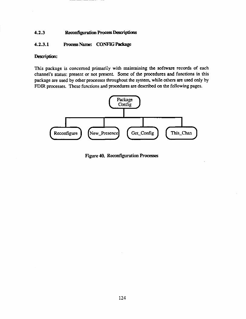
4.2.3
4.2.3.1
R~guratimh.ocessDescriptions
procesSName: CONFIGPackage
Desaiptim:
This package is concerned primarily with maintaining the software records of each channel's status: present or not present. Some of the procedures and functions in this package are used by other processes throughout the system, while others are used only by FDIR processes. These functions and procedures are described on the following pages.
Package (7) I
I I I I
Figure 40. Reconfiguration Processes
124

4.2.3.1.1 procesS Name: RECONFIGURE
Inputs Reconfigand record identifying the channel and whether it is failed or recovered
out?- * Configurationrecord
Monitor interlock
Integer version of configuration record STATUS-INFO array for display task
This procedure is called in four different situations:
system startup a channel has failed a channel has been recovered after a failure (mal recovery) a channel has passed its probation period after recovery (permanent recovery)
In each situation, appropriate actions are taken to update variables reflecting the current configuration and enable/disable the Monitor Interlock.
At system startup:
THE-CONFIG, TRIAL-CONFIG and CHANS-IN-SYNC are set to reflect the channels which successfully synchronized. INT-CONFIG, INT-TRIAL-CONFIG and IN"-CHANS-IN-SYNC are set to correspond to THE-CONFIG, TRIAL-CONFIG and CHANS-IN-SYNC, respectively. The STATUS-INFO array is set to indicate whether each channel is failed or active and the time it failed or became active. The Monitor Interlock is engaged for the active channels and disengaged for all others.
When a channel has failed:
THE-CONFIG and TRIAL-CONFIG are updated to reflect the failed channel. If the failure was other than a data exchange failure, CHANS-IN-SYNC is also updated to reflect the failed channel. The STATUS-INFO array is updated to reflect the failed channel.
125

The failed channel's Monitor Interlock is disengaged. INT-CONFIG, INT-mL-CONFIG and INT-CHANS-IN-SYNC are set to correspond to THE-CONFIG, TRIAL-CONFIG and CHANS-IN-SYNC, respectively.
When a channel has been recovered after a failure (trial recovery);
CHANS-IN-SYNC and TRIAL-CONFIG are updated to reflect the recovered channel. I"'-CHANS-IN-SYNC and INT-'I'RIAI-CONFIG are set to correspond to CHANS-IN-SYNC and TRIAL-CONFIG, respectively.
When a channel has passed its probation period after recovery (permanent recovery);
THE-CONFIG is updated to reflect the recovered channel. The STATUS-INFO array is updated to reflect the recovered channel. INT-CONFIG is set to correspond to THE-CONFIG. The recovered channel's Monitor Interlock is engaged.
4.2.3.1.2 ProcessName: NEW - PRESENCE
Inputs: Integer value of old configuration Integer value of new configuration
atplts: Reconfigand record identifying the channel that is different and whether it was added or deleted
This function examines two integer versions of the configuration and figures out which channel is different between the two versions. If a channel has been added it creates a reconfig-cmd record for the channel with a reason of ENABLE-T; if a channel has been deleted it creates a reconfig_cmd record with a reason of DISABLE.
126

4.2.3.1.3 procesS Name: GET-CONFIG
Inputs: Integer version of current configuration
u Record version of current configuration
This function is called by local system service and UO system service routines that want to know the current configuration. The function takes the integer version of the current configuration and converts it to a record of type configuration.
It is necessary to obtain the current configuration by calling this routine rather than by simply making a local copy of the current configuration record. This is because Ada generates multiple instructions to move the configuration record, rather than using a single M0VE.L instruction. Thus if a routine were to be interrupted while moving the record, when it got control again the record may have changed, due to an intervening execution of Fast FDIR, Transient FDIR, or Lost Soul Sync. To make sure a consistent copy of the configuration record is obtained, it is necessary to use this function.
4.2.3.1.4 Process Name: THIS_CHAN
Inputs: Channel id from the Monitor Interlock Register
oum Channel id of type channel-id
This function reads the channel id from the Monitor Interlock register and converts it to a variable of type channel-id with a value of A, B, or C.
127

4.2.4 Logging procesf Descriptions
4.2.4.1 User E m Logs
Logging routines are included in the following packages:
RECORD_FDIR-ERRORS FDIR-ERROR-LDG RECORD-RECONFIGS RECONFIG-LOG NON-CONGRUENT-LOG
The non-congruent log itself is contained in the NON-CONGRUENT-DATA package.
4.2.4.1.1 Process Name: RECORD-F'DIR-ERROR,CREPORT_ERROR
I n p w Information to be entered in the error log
This routine logs faults detected by the Fast-FDIR task. FDIR-ERROR-LOG.ENTER, to make the log entry.
It calls a subroutine,
4.2.4.1.2 Process Name: F'DIR - ERROR-LOG.ENTER
Inputs: Information to be entered in the error log
hm Entry in the error log Counters to indicate number of entries and next available slot in the error log
This routine creates a new entry in the FDIR error log. This log has room for 20 entires; after all available slots are filled the next entry goes at the top of the log. Indices to the oldest and newest entries in the log are maintained, along with a count of the number of entries.
128

4.2.4.1.3 Process Name: RECORI-RECONFIGS.REPORT-RECONFIG
Inputs: Information to be entered in the rcconfiguration log
outp1oi: None
This routine logs all reconfigurations that occur. It calls a subroutine, RECONFIG-LOG.ENTER, to make the log entry.
4.2.4.1.4 Process Name: REC0"IG-LOG.EN"ER
Inpuls: Information to be entered in the reconfiguration log
hw Entry in the reconfiguration log Counters to indicate number of entries and next available slot in the log
This routine creates a new entry in the reconfiguration log. This log has room for 20 entires; after all available slots are filled the next entry goes at the top of the log. Indices to the oldest and newest entries in the log are maintained, along with a count of the number of entries.
129
4.2.4.1.5 Process Name: NON~CONGRUENT~LOG.LOG~NONCONGRU~EVENT
In*: Strings identifying logger and information to be logged
u Entry in non-congruent log
This routine creates a new entry in the non-congruent log. This log has room for 16 entries; after all available slots are fded the next entry goes at the top of the log. An index to the next available slot is maintained, along with a count of the number of entries.
In order to determine the next available slot, two special subroutines must be called, since different channels will be at different positions in their respective logs and computing a new position should not throw them out of sync. Refer to INCR-NC-LOG-INDEX and SET-UP-CURRENT-ENTRY which follow.
4.2.4.1.6 Process Name: NON - CONGRUENT~LOG.INCR~NC~LOG~INDEX
Inputs: Current NC-LOG-INDEX - Updated NC-LOG-INDEX
The non-congruent log has room for 16 entries; the index varies between 0 and 15. This routine increments it and resets it to 0 when it gets past 15. This must be done without actually checking the value because different channels may have different indices, and such a check might throw them out of sync. This assembly language routine uses an AND instruction to set a 16 to 0.
130

4.2.4.1.7 procesS Name: NON-CONGRUENT-LOGSET_VP_CURRE"TRY
Inputs: Index to the noncongruent log
Address of next available position in the non-congruent log
Description:
This routine takes an index value and converts it to an actual address within the non- congruent log. This special routine is required because the Ada implementation of this operation treats an index of 0 as a special case. Since different channels may have different indices to the non-congruent log, this special case could throw a channel out of sync. This routine also speeds up the computation by using a shift instruction rather than a multiply.
4.2.4.1.8 Process Name: NON - CONGRUENT-DATA Package
Description:
This package contains data items whose values may legitimately differ across channels and which are therefore kept in this special area which is neither aligned nor scrubbed. Limitations of the Ada compiler force this package to reside at an absolute address; the high end of RAM was chosen for convenience. There are three types of data in this package:
1) channelid 2) input values which may differ across channels 3) the non-congruent log
The channel id is obtained at system startup by reading the value from the hardware register and converting it to the channel-id type defined in the Config package.
Input values which may differ across channels include local copies of the error latches, local results of selftests, and data read from input devices.
The non-congruent log contains information about selected faults which occurred. This log is not reinitialized after a software restart so that information about the cause of the restart is available.
131

4.2.4.2 Debugging Lo@
The FDIR software also has the facility to record ongoing events (both no& and error conditions) in a log which cannot be displayed but must be inspected manually by the system engineer. The subroutine to update this log is described in the following section.
4.2.4.2.1 Process Name: DEBUG-LOG
Inputs: Two identifying words passed by the caller
hm Either a new entry in the log, or an addition to the count field of the previous entry
This routine maintains a trace log so that the sequence of events in the FIT at any particular time may be known. This log is circular; after all available slots are filled the next entry goes at the top of the log.
In addition to recording the caller id and an additional word of infoxmation, which are passed as parameters, the routine maintains a count of the number of times it has been called in succession with identical parameters. Thus, for example, the selftest procedure to write RAM patterns calls this routine once for every word that it tests. There are not n entries in the log, however; rather there is only one entry with a field to indicate that the entry was made n times in succession.
The current value of the system timer is also saved for each entry.
This procedure is written in assembly language to minimize its impact on system performance.
132

5.0 GPCSTATUSREPORTER
I
The purpose of the GPC Status Reporter is to collect and disseminate information about the status of the various AIPS components. Hardware status information is provided by the various redundancy managers, while software status information is provided by the operating system. The collected information is made available to an operator, for manual decision-making, and to the System Manager software function, for automated decision- making. The three major functions of the Status Reporter are shown in Figure 41.
I
GFC STATUS U REPORTER
Figure 41. GPC Status Reporter Functions
5.1 GPC Status Reporter Functional Requirements and Design
AIPS is a distributed system with redundancy management functions at each site. Some of these functions are located at every site (e.g., GPC FDIR, 10s FDIR and ICIS FDIR) while other functions are located only at selected sites (e.g., the VO Network Manager and the IC Network Managers). The GPC Status Reporter, which resides on both the CP and IOP at every site, must collect and disseminate status information provided by every function resident at its own particular site.
Figure 42 shows the flow of the status information. The shaded circles in this figure indicate functions executed only at selected sites, while the unshaded circles indicate functions executing at every site.
133
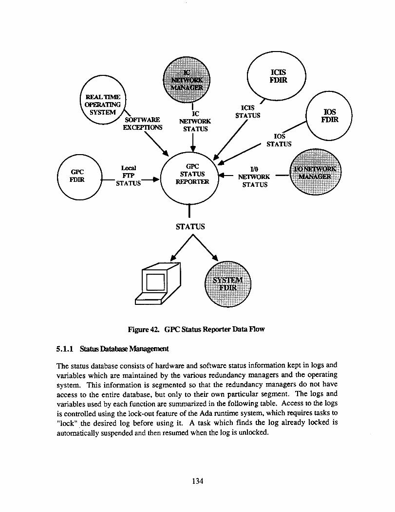
ICIS STATI JS IC
E
ICIS IC
STATUS
GFC STATUS - NETWORK
STATUS m W
STATUS
Figure 42. GFC Status Reporter Data Flow
5.1.1 StatusDatabaseManagemnt
The status database consists of hardware and software status information kept in logs and variables which are maintained by the various redundancy managers and the operating system. This information is segmented so that the redundancy managers do not have access to the entire database, but only to their own particular segment. The logs and variables used by each function are summarized in the following table. Access to the logs is controlled using the lock-out feature of the Ada runtime system, which requires tasks to "lock" the desired log before using it. A task which finds the log already locked is automatically suspended and then resumed when the log is unlocked.
134

REDUNDANCY MANAGER
GPC FDIR
Real Time Operating System
IC Network Manager
STATUS DATABASE SEGMENT
FTP Configuration FDIR Error Log FlT Reconfiguration Log Non-Congruent Log
Software Exception Log
IC Network Configuration IC Network Error Log IC Network Reconfiguration Log
ICIS Configuration ICIS Error Log ICIS Reconfiguration Log
10s Configuration 10s Error Log 10s Event Log
VO Network Configuration VO Network Error Log VO Network Event Log
Figure 43. Status Database
5.1.2 Status Display
The Status Display software displays. the status information currently available about a particular hardwadsoftware component in response to an operator query. Each processor card in a GPC has a Dual Universal Asynchronous Receiver/Transmitter (DUART) chip with two channels, which allows the processor to communicate with a display device such as a CRT or personal computer over two RS-232 lines. Two types of displays are currently available, one on a CRT and one on a Macintosh computer, and each uses its own RS-232 line. The functions which provide these displays are shown in Figure 44.
135

STATUS DISPLAY
Figure 44. Status Display
The CRT-Display function a lows an operator to communicate with a GPC via a VT2 1 or VT240 terminal. There are three instances of the CRT-Display task, one to serve each channel, so that a terminal may be connected to each channel and three different displays called up and monitored by an operator if desired. The three tasks run at the lowest priority. All three tasks execute on all three channels but the input to any one task is only from the channel being served by the particular task. Specifically, the CRT-Display task for Channel A executes on all channels but its input comes from Channel A's DUART and must be distributed to the other channels by means of the data exchange before any processing is done; output is then sent only to Channel A's DUART. Similarly, the CRT-Display task for Channel B executes on all channels, but its input, which comes from Channel B's DUART, is distributed before being processed, and output is sent only to Channel B's DUART.
The Mac-Display function allows an operator to communicate with a GPC via a Macintosh computer. The Mac-Display task sends the status information to a Macintosh computer where it is formatted into a pictorial or tabular display. This moves the complex and time- consuming routines necessary to create user-friendly displays from the GPC to the Macintosh.
There is only one instance of the Mac-Display task, so communication can take place with only one FTP channel at any given time. The channel that will receive and transmit data is chosen according to channel identification and availability. Channel A has the highest priority and channel C the lowest. If Channel A is active, its DUART is responsible for the Macintosh link. If the channel currently driving the Macintosh display fails, the MAC-Display software automatically switches to the next available DUART. The operator requests the desired displays from the FTP by using Macintosh menus; several
136
displays may be called up and monitored simultaneously by using Macintosh windows. The Macintosh may communicate with the GPC over any distance, and remote users may connect their Macintosh to a GPC using a modem and telephone line.
5.1.3 Status Reporting
The Status Reporting function sends all currently available status information to the System Manager, either periodically or in response to a fault. Since the System Manager has status information from all sites, it can form a global view of things and identify faults in a way in which the individual redundancy managers, with only their local viewpoint, cannot. The System Manager is thus able to identify transient faults, isolate the cause of ambiguous faults, and determine the need for function migration.
5.2 GPC Status Reporter Software Specifications
5.2.1 Status Database Management procesS Descriptions
The status database management processes are specific to each of the database segments and are described in the section pertaining to the appropriate redundancy manager. These processes are summarized in the following table.
137

138
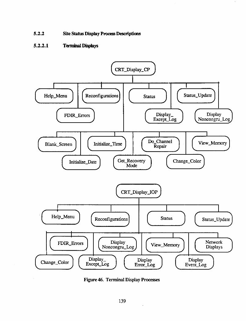
5.2.2
Help-Menu
5.2.2.1
status Status-Update
Site Status Display Process Descriptions
TerminalDisplays
I
CRT-Display-CP G 1
0 FDIR-Errors Display- Except-Log
Display
( ~ ) l (E) 7 7 [ Ini[lalirc_Date) [ Get-Recovery Mode
View-Memory
7
Change-Color u CRT-Display-IOP
I
(-)(*) (Dllplsy) (e) Except-Log Emr-Log Even t-Log Change-Color
Figure 46. Terminal Display Processes
139

5.2.2.1.1 h.ocess Name: CRT-Display-CP
Inputs: Channel id User commands from a texminal - Invalid command message to terminal
This task provides a means by which an operator may communicate with the FTP, specifically the CP, via a VT220 or VI240 terminal c o ~ e c t e d to an RS232 port. There are three instances of this task, one for each channel, so that simultaneous input from three different channels may be processed.
This task runs at the lowest priority and executes periodically. However, the periodicity is not achieved by using the Scheduler functions, but rather by a delay statement at the end of the task’s main loop. The task is initially started by a rendezvous with the main program which identifies to each instance of the task which channel it is serving.
Within its main loop, the task calls the procedure INPUT-WAITING to determine if new input has come in from the RS232 port. If it has, the input command is read and an appropriate routine is called to process it. If there is no new input and the last command entered was an ST command (Status Display), the time and date on the status display are updated.
140
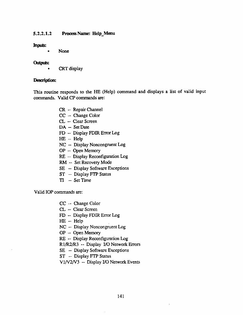
5.2.2.1.2 Process Name: Help-Menu
Inputs: None - CRT display
This routine responds to the HE (Help) command and displays a list of valid input commands. Valid CP commands are:
CR -- Repairchannel CC -- Change Color CL -- Clearscreen DA -- SetDate FD -- Display FDIR Error Log HE -- Help NC -- Display Noncongruent Log OP -- OpenMemory RE -- Display Reconfiguration Log RM -- SetRecoveryMode SE -- Display Software Exceptions ST -- Display FTPStatus TI -- SetTime
Valid IOP commands are:
CC -- Change Color CL -- Clear Screen FD -- Display FDIRErrorLog HE -- Help NC -- Display Noncongruent Log OP -- OpenMemory RE -- Display Reconfiguration Log Rl/R2/R3 -- Display VO Network Errors SE -- Display Software Exceptions ST -- Display FTPStatus Vl/V2/V3 -- Display VO Network Events
141
5.2.2.1.3 procesSName: FDIR - Ernws - CRT display
This routine responds to the FD command (Display FDIR Errors). It formats the FDIR error log and outputs it to a CRT. For each entry in the log, the type of error, the faulty channel and the date and time of the error are displayed. Additional information is displayed for the memory selftest errors (RAM scrub, RAM pattern, shared memory scrub, and PROM sum check): the address containing the fault, the actual value at that address, and the expected address.
5.2.2.1.4 Process Name: Reconfigurations
Inputs: Reconfiguration log
oum CRT display
This routine responds to the RE (Display Reconfigurations) command. It formats the reconfiguration log and outputs it to a CRT. For each entry in the log, the reconfiguration event (e.g., power on, disable, enable), the processor, the time and date of the event, and the channel(s) involved are displayed.
142

wuf= Software exception log - CRT display
This routine responds to the SE (Display Software Exceptions) command. It formats the software exception log and outputs it to a CRT. For each entry in the log, the date and time of the error, where it occurred (subroutine or task id), and a brief description of the exception are displayed.
This subroutine is declared as EXTERNAL so that it may be used by the runtime system to display the software exception log in the event of some catastrophic error which forces a system shutdown.
5.2.2.1.6 procesS Name: Status
Inputs: Current configuration
htpds: CRT display
This routine responds to the ST (Display FTP Status) command. It formats the initial display which shows the current configuration of the FTP (which channels are up, which are down, and failure times). the STATUS-UPDATE routine (see following section) is periodically called to update the date, time and any change in channel status.
After this initial display has been drawn,
143

5.2.2.1.7 procesSName: Status-Update
Inpuk Cumntconfiguration STATUS-INFO m y STATUSCHANGED array
atpds: Time, date and channel status fields in status display
This routine updates only the time, date and channel status fields in the status display. To make the routine as efficient as possible, the channel status is updated on the display only when it has changed. The STATUS-INFO and STATUS-CHANGED arrays are used to keep track of when the status changes (from online to failed and failed to online) and whether that changed status has been reflected in the display.
5.2.2.1.8 procesS Name: DisplayNoncongru - Log Inpk
Non-congruent log Channel id whose log is to be displayed
hm CRT display
Description:
This routine processes the NC command, which is used to display the non-congruent log for a particular channel. After the NC command has been entered, this routine prompts the operator for the specific channel id. The log is then copied from the resident channel to all channels using a single-source data exchange. For each entry in the log, the date and time of the error, where it occurred (subroutine or task id), and a brief description of the non- congruent event are displayed.
5.2.2.1.9 ProcessName: Blank - Screen
Inpuk None
ouw Blank CRT screen
Description:
This command responds to the BL (Blank Screen) command. It causes the CRT screen to be cleared.
144
5.2.2.1.10 h.ocess Name: InitMzt-Date
hw New value for date - Local-GPC-Time variable in shared memory
This routine processes the DA command, which is used to enter the current date. After the DA command has been entered, this routine prompts the operator for the date, which must be entered in the format DD-MON-YYYY. It then calls the SET-DATE subroutine provided by the Time Manager package to update the global time record, which resides in shared memory.
5.2.2.1.11 pn>cess Name: Initialize-Time
Inputx New value for time
&- e Local-GPC-Time variable in shard memory
This routine processes the TI command, which is used to enter the current time of day. After the TI command has been entered, this routine prompts the operator for the time of day, which must be entered in the format HH:MM:SS. It then calls the SET-TIME subroutine provided by the Time Manager package to update the global time record, which resides in shared memory.
145
5.2.2.1.12 procesS Name: Get-Recovery-Mode
Inpub:
Channel id Recovery mode (automatic or on-command)
outplts Channel-Recovery-Mode array
This routine processes the RM command, which is used to indicate the recovery mode (either automatic or on-command) for a specified channel. After the RM command has been entered, this routine prompts the operator for the specific channel id. The information is then stored in the Channel-Recovery-Mode array in the FDIR-Globals package, where it will be referenced by Transient FDIR.
5.2.2.1.13 procesS Name: Do-Channel-Repair
Inputs: Id of repaired channel Cunent configuration Channel-Recovery-Mode array
hw Channel-Repaired array
This routine processes the CR command, which is used to indicate that a failed channel has been repaired. After the CR command has been entered, this routine prompts the operator for the specific channel id. An error message is displayed for the operator if the specified is not down or if its recovery mode is automatic. Otherwise, the Channel-Repaired array in the FDIR-Globals package is updated to reflect the repaired channel, and the information will be used subsequently by Transient FDIR.
146
5.2.2.1.14 PrwessName: Change-Color
Inputs: Id of desired color scheme
out@= Command to terminal to set color characteristics
This routine processes the CC command, which is used to indicate the desired color scheme for a IT240 terminal. After the CC command has been entered, this routine lists codes for each of the possible color schemes and prompts the operator to make a selection. The correct bit pattern is then written to the terminal to select the desired colors.
147

5.2.2.1.15 Process Name: Open-Memo~y
Inpub: Memory address
outplts: Voted and individual channel values for specified address
Description:
This routine processes the OP command, which allows an operator to display and modify the contents of specified memory addresses. After the OP command has been entered, this routine prompts the operator for an address and then displays both a voted value and individual channel values for the specified address. If a channel is down, I*****' is displayed for its value. If a channel disagrees with the voted value, its own value is displayed, otherwise '-----I is displayed to indicate its agreement with the voted value.
After the value of the specified address has been displayed, the operator types another command to indicate what he wants to do next. The possible actions are:
N Display the next address P Display the previous address A - -
Q
Display a new address (operator will be prompted for the new address) Modify current address (operator must type in new value at the repositioned cursor) Exit (Help screen will then be displayed)
148
5.2.2.1.16 procesS Name: CRT-Display-IOP
Inputs: Channel id Terminalinput
OutpIOs: Invalid command message to texminal
This task provides a means by which an operator may communicate with the FTP, specifically the IOP, via a Vn20 or VT240 terminal connected to an RS232 port. There are three instances of this task, one for each channel, so that simultaneous input from three different channels may be processed.
This task runs at the lowest priority and executes periodically. However, the periodicity is not achieved by using the Scheduler functions, but rather by a delay statement at the end of the task's main loop. The task is initially started by a rendezvous with the main program which identifies to each instance of the task which channel it is serving.
Within its main loop, the task calls a procedure, INPUT-WAITING, to determine if new input has come in from the RS232 port. If it has, the input command is read and an appropriate routine is called to process it. If there is no new input and the last command entered was an ST command (Status Display), the time and date on the status display are updated.
Most of the commands handled by this task are also handled by the CRT-Display-CP task, and the routines to process these commands have been described earlier in this section. The reader is referred to previous subsections for information on the CC, CL, FD, HE, NC, OP, RE, SE, and ST commands.
149
5.2.2.1.17 procesS Name: Display-Event-Log
h- Event log for the specified VO network - CRT display
This routine responds to V1, V2 and V3 (Display Event Log n) commands. It formats the event log for the specified VO network and outputs it to a CRT. Each entry in the log identifies the time and date of the event, the relevant network, the id of the subroutine logging the event, and a brief description of the event
5.2.2.1.18 Process Name: Dkplay-Error-~
Inputs: Error log for the specified VO network
htplts: CRT display
Description:
This routine responds to R1, R2 and R3 (Display Error Log n) commands. It formats the error log for the specified VO network and outputs it to a CRT. Each entry in the log identifies the time and date of the fault, the relevant network, the channel and node reporting the fault, an identifier of the test which detected the fault, and a brief description of the fault.
5.2.2.1.19 Process Name: WO Network Displays
Inpuls: YO Network Status Information
htplts: CRT display
These subroutines use the information maintained by the VO Network Manager about the networks to format a pictorial display of the VO networks. These subroutines are described in Section 3.6 of the "Input/Output Network Management Software" document, May 1988.
150
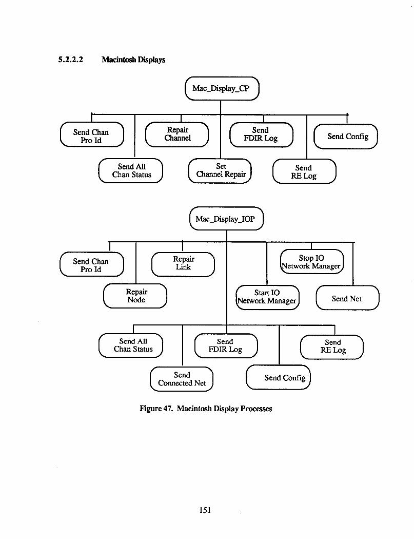
5.2.2.2 Macintosh Displays
1 I (-) (T) Repair Node
I I I t Send Config
Send Chan Repair Send Pro Id Channel FDIR Log
stop IO
Send Net start IO
twork Manager
Chan Status Channel Repair
Mac-Display-IOP v
Figure 47. Macintosh Display Processes
151

5.2.2.2.1 ProcessName: Mac - Display-CP
In- * h n t configuration
Commands from Macintosh
outprts None
This task provides a means by which an operator may communicate with the FIT, specifically the CP, via a Macintosh computer. The communication takes place by means of an RS232 port, although it is a different port that that used by the terminal display task (refer to Section 5.2.2.1.1 ). Unlike the terminal display tasks, there is only one instance of this task, so commands from the Macintosh may come into only one channel at any given time.
This task runs at the lowest priority and executes periodically. However, the periodicity is not achieved by using the Scheduler functions, but rather by a delay statement at the end of the task's main loop.
Within its main loop, the task calls the procedure INPUT-WAITING to determine if new input has come in from the RS232 port. If it has, the input command is read and an appropriate routine is called to process it. If there is no new input, it sends the current configuration, date and time to the Macintosh.
5.2.2.2.2 Process Name: SendChanProId
Inpuk Processor id Channel id
OutPuD; Processor and channel id to Macintosh
Desaiption:
This routine responds to the ID (Send Id) command. It transmits the processor id (CP or IOP) md channel id of the processor to which the Macintosh is connected.
152

5.2.2.2.3 Pmxs Name: SendAllChanStatus
Inpuk None
outplts None
This routine responds to the ST (Display FTP Status) command. It sends the status of all FlT channels to the Macintosh by calling the subroutine SendChanStatus, which sends the status (online or failed) of the individual channels.
5.2.2.2.4 Process Name: RepairChannel
Inputs: Current configuration Channel-Recovery-Mode array
hmb Channel-Repaired array
Description:
This routine processes the CR command, which is used to indicate that a failed channel has been repaired. If the recovery mode for the specified channel is On-Command, the Channel-Repaired array is updated to reflect the rep&, for the automatic recovery mode the command is ignored. The information in the Channel-Repaired array is subsequently used by Transient FDIR.
5.2.2.2.5 Process Name: SetChannelRepair
Inputs Recovery mode (automatic or on-command)
owub Channel-Recovery-Mode array
Description:
This routine processes AU and OC commands, which are used to indicate the recovery mode to be used after a failure (either automatic or on-command). The same recovery mode is assigned to all channels, and the information is stored in the Channel-Recovery-Mode array.
153
5.2.2.2.6 Process Name: SendFDIRLog
w)ut= FDIR Error Log
outplts Error log entries to Macintosh
Desaiption:
This routine responds to the FD (Display FDIR Errors) command. It sends entries from the FDIR Exror Log to the Macintosh. Rather than sending all entries currently in the log, the routine sends only those entries that have been made since the last time entries from the log were sent. For each log entry that is transmitted, the type of error, the faulty channel and the date and time of the fault are transmitted. Additional information is transmitted for the memory selftest errors (RAM scrub, RAM pattern, shared memory scrub, and PROM sum check): the address containing the fault, the actual value at that address and the expected value.
5.2.2.2.7 Process Name: Sendconfig
Inpk Integer version of current configuration
outputs Integer version of current configuration to Macintosh
This routine transmits the integer version of the current FTP configuration to the Macintosh.
154
5.2.2.2.8 Process Name: SendRELog
Inputs:
outm
Reconfiguration log
Error log entries to Macintosh
This routine responds to the RE (Display Recodigurations) command. It sends entries from the Reconfiguration log to the Macintosh. Rather than sending all enmes currently in the log, the routine sends only those entries that have been made since the last time entries from the log were sent. For each log entry that is transmitted, the reconfiguration event (e.g., power on, disable, enable), the processor, the time and date of the event, and the channel(s) involved are transmitted.
5.2.2.2.9 procesS Name: Mac-Display-IOP
Current configuration Commands from Macintosh
This task provides a means by which an operator may communicate with the FTP, specifically the IOP, via a Macintosh computer. The communication takes place by means of an RS232 port, although it is a different port that that used by the terminal display task (refer to Section 5.2.2.1.16). Unlike the terminal display tasks, there is only one instance of this task, so commands from the Macintosh may come into only one channel at any given time.
This task runs at the lowest priority and executes periodically. However, the periodicity is not achieved by using the Scheduler functions, but rather by a delay statement at the end of the task's main loop.
Within its main loop, the task calls the procedure INPUT-WAITING to determine if new input has come in from the RS232 port. If it has, the input command is read and an appropriate routine is called to process it. If there is no new input, it sends the current configuration, date and time to the Macintosh.
Most of the commands handled by this task are also handled by the Mac-Display-CP task, and the routines to process these commands have been described earlier in this section. The reader is referred to previous subsections for descriptions of the routines which process the ST, FD, and RE commands.
155

5.2.2.2.10 procesS Name: RepairNode
Inpu&: Nodeid Portid - None
Description:
This subroutine processes the RN (Repair Node) command. It reads the node id and port id sent from the Macintosh and calls the Restort-Node-or-Link subroutine which is part of the I/O Network Manager. (The reader should refer to pp. 64 and 69-70 of "Input/Output Network Management Software, May 1988, for further information.)
5.2.2.2.11 procesS Name: RepairLink
Inpulx Nodeid Portid
This subroutine processes the RL (Repair Link) command. It reads the node id and port id sent from the Macintosh and calls the Restore-Node-or-Link subroutine which is part of the UO Network Manager. (The reader should refer to pp. 64 and 69-70 of "Input/Output Network Management Software, May 1988, for further information.)
5.2.2.2.12 €"xxssName: Start - - IO Network - Manager
Inputs: Networkid
h r n b Network manager database
This routine is called when Al, A2 or A3 (Activate VO Network) commands are received. This routine is part of the I/O Network Manager and is discussed in Section 3.1.1 of "Input/Output Network Management Software", May 1988.
156
5.2.2.2.13 Process Name: Stop-IONetWorkManager
Inputs: Network id
outplts Network manager database
This routine is called when D1, D2 or D3 (Deactivate I/O Network) commands are received.
5.2.2.2.14 procesS Name: SendNet
Inputs: Network-Info array
Network status info to Macintosh
This procedure responds to N1, N2 and N3 commands, which are used to request a complete display of a particular network. Using the Network-Info array, which is maintained by the I/O Network Manager, this procedure transmits the status of every node and link in the specified network to the Macintosh.
5.2.2.2.15 Process Name: SendConnectedNet
Inputs: Active-Nets array
Id of connected network(s) to Macintosh
This routine responds to the CN (Send Connected Network) command. It sends the id of all the networks currently connected to the FlT.
5.2.3 Status Reporting Process Descriptions
Status reporting has not been implemented for the centralized AIPS configuration and so is not discussed in this section of the document.
157

6.0 LOCALTIMEMANAGER
Maintaining and disseminating the current time is the responsibility of the Local Time Manager, which resides on each GPC. This task maintains the current time by periodically updating a software variable to reflect a time consistent across all AIPS sites as well as to reflect elapsed time on the local GPC. This task also provides the current time to all software processes, including the runtime system. These responsibilities are divided between two functions, the Local Timekeeper and the System Timekeeper, as shown in Figure 48.
TIME MANAGER w TIMEKEEPER TIMEKEEPER
Figure 48. Local Time Manager
6.1 Local Time Manager Functional Requirements and Design
The Local Timekeeper function of the Local Time Manager is required for both the centralized and distributed configurations of AIPS. The System Timekeeper function, however, is used only in the distributed configuration, The flow of information through these two functions is shown in Figure 49.
6.1.1 LocalTimekeper
The Local Timekeeper maintains the current time on each GPC. It updates the current time by periodically adding the elapsed time as measured by the hardware timer. If the GPC is part of a distributed AIPS configuration, it also updates the current time based on calculations made by the System Timekeeper so that the time is consistent across all GPCs in the configuration. The Local Timekeeper also provides the current time, either in 24- hour clock time, clock ticks or millisecond time, to all software processes that request it.
PRECEDING PAGE BLANK NOT FILMED
159

External Date &Time
System T i
\ \
External Date &Time
\
~ __._._.____ ER -------9 I.U
ne Tin
Time Database
LOCAL TIMEKEEPER
Initial GFC INlT Time 0
Current 24-hr Clock
Time
TASKS
Current Clock Ticks or Millisecond
OPERATING SYSTEM
Figure 49. Information Flow through the Local Time Manager
160

The Local Timekeeper has three main components, the Time Database, the Time Database Manager and Calendar Extensions, which are shown in Figure 50.
TIMEKEEPER u EXTENSIONS
I I I
Figure 50. Local Timekeeper Components
6.1.1.1 'IEmeDatabase
The Time Database consists of the hardware timer and software data structures used to maintain the current time. The hardware timer is located on the shared bus, and the data structures are located in shared memory, so the database may be accessed by both the CP and IOP.
The hardware timer is implemented as a 32-bit counter driven by the GPC's fault-tolerant clock. Since the fault-tolerant clock signal is generated every 4.125 psec, each tick of the hardware timer represents 4.125 pec .
The following data structures are used to maintain the current time.
Local-GPC-Time. This record contains the most recent value of the current time as computed by the Time Database Manager, along with the value of the hardware timer corresponding to that time. This time is represented internally by a record containing the year, julian day, and seconds of the day. It is initialized at power on to a default value provided by the operating system and is set to an actual &e., external) time and date after the GPC has been synchronized.
161

Timer offset. Because the hardware timcr cannot be set to any value other than 0, a software variable is required so that the timer may be aligned among unsynchronized channels. The offset represents some previous value of the hardware timer and must be added to the current timer value to obtain a true timer reading.
Delta Time. This value is provided by the System Timekeeper. It is used to correct the local GPC time so it corresponds to the universal time.
Average Drift Rate. This value is also provided by the System Timekeeper and reflects the extent to which local GPC time is drifting from the universal time.
6.1.1.2 'LEmeDatdbaseManager
The Time Database Manager updates the Time Database with the current time and provides the current time to any software process, either application or operating system, that requests it. Applications typically need the current time relative to the start of the mission and to a granularity of seconds, while the runtime system needs the current time relative to only an hour ago, but to a granularity of clock ticks or milliseconds. The Time Database Manager provides both types of current time; it also provides functions to manipulate clock tick and millisecond time such as comparing or differencing two times.
Updates to the current time (the LocalGPC-Time variable) are made by only one function (Update-Local-Time) on only one processor (the IOP). The update is made in such a way that no other task or processor can read the variable while it is being updated. After the variable has been updated, it is copied to each processor's local RAM, where it is referenced whenever the current 24-hour clock time is requested. The variable is read in such a way that a task will not be interrupted before the read is completed, this ensures that a reading task will always obtain a logically consistent time.
As seen in Figure 28, the Time Database Manager has four functions:
Initializing the time and date, i.e., setting the time and date to an initial value at power-on;
Setting the time and date, Le., setting the time and date to some actual (Le., external) time and date after the GPC has been initialized and synchronized;
Updating local GPC time, i.e., using inputs from the hardware timer and the System Timekeeper to update the current time;
Manipulating clock tick and millisecond time, for example, computing the difference between two successive values of the hardware timer, or comparing two times.
162

6.1.1.2.1 Initialiae’Ih~
The Initialize Time routine sets the date segment of the Local-GPC-The record in the Time Database to the default initialization value supplied by the operating system. It sets the time segment of the Local-GPC-Time record to zero and clears and restarts the hardware system timer. Interrupts are disabled and the shared bus locked during this update. The InitiaIize-Time routine is called only once by the operating system and on only one processor (the IOP).
6.1.1.2.2 ImmediateSetTimeandDate
The Set Time and Set Date routines set the time and date segments, respectively, of the Local-GPC-Time record to the values supplied by the caller. Interrupts are disabled and the shared bus locked during this update. The Set-Time and Set-Date routines are also invoked by the System Timekeeper function. They are executed on only one pmcessor (the IOP).
6.1.1.2.3 Update Local Tim
The current time is updated by adding to it the time elapsed since the current time was last computed. The elapsed time is computed by finding the difference between the value of the hardware timer when the current time was last updated and its current value. The computation of current time is summarized as follows:
Local-GPC-Time = Local-GPC-Time + (current-timer-value - old-timer-value)
Because the time is stored in shared memory and because the time may be requested by a user (via the Ada CALENDAR.CLOCK function) at an unpredictable frequency, thus incurring a potentially large overhead in shared memory access time, the calculation of current GPC time is divided into two phases. In the first phase, one processor (the IOP) computes Local-GPC-Time once a second and stores it in the Time Database. A copy of Local-GPC-Time is also saved in the processor’s local memory. In the other processor, Local-GPC-Time is not calculated, but only copied from shared to local memory, also once a second. LocalGPC-Time is thus maintained in shared memory to within one second of the actual time. In the second phase, requests for the precise current time, which are made by calling the Ada CALENDAR.CLOCK routine, are satisfied by computing the actual time as above using the locally maintained copies of Local-GPC-Time. In this manner the overhead of accessing shared memory is reduced, and the cost of computing the precise time is incurred only by those routines which request it.
The Update-Local-Time routine must correctly account for the rollover of the hardware timer. It must also correctly account for the rollover of the 24-hour time values, such as seconds at the end of the day and julian days at the end of the year. The CLOCK routine in
163

the Ada CALENDAR package must also account for rollover when computing exact time on demand.
In the Distributed AIPS system, the Updatc~Local-Timc routine must occasionally adjust the value of the time to account for hardware timer drift among the local GPCs. A value to be used to modify accordingly the result of the above time computation is maintained in the Time Database by the AdjustTime routine of the System Timekeeping function.
6.1.1.2.4 Time Utilities
The Time Database Manager also contains a number of auxiliary functions to provide time services to the operating system. These include (1) an align timer function which is called by the Lost Soul Sync task in order to update the timer offset variable and then clear and restart the hardware timer, (2) a function to access the hardware timec and (3) functions to provide the current time directly from the hardware timer (either in clock ticks or in clock ticks converted to milliseconds) and functions to add and compare time presented in this format. These functions are required for operating system scheduling services.
6.1.1.3 Calendar Extensions
Calendar Extensions provide the standard time functions specified in the Ada Language Reference Manual along with additional functions that allow A P S application users to manipulate or examine time in additional ways. The Ada-supplied package CALENDAR (cf., MIL-STD-l815A, Section 9.6) includes the standard function CLOCK, which returns the current 24-hour time. Other functions extract the year, month, day, and sec- onds, as specified in the ADA Language Reference Manual.
The CLOCK function enables any application to obtain the current 24-hour time, which is computed in the following manner:
time = old-time + (current-timer-value - old-timer-value)
where time is calculated by adding the amount of time elapsed since time was last updated (old-time). The elapsed time is computed by figuring the difference between the current value of the hardware timer and its value when the time record was last updated.
The CLOCK routine must correctly account for the rollover of the hardware timer. It must also correctly account for the rollover of the internal time values, such as seconds at the end of the day and julian days at the end of the year.
The Calendar package implemented for AIPS includes additional functions that are not predefined by Ada, such as a function to determine the julian day number of the current day and a function to convert a variable of julian date type to a variable of the private type time.
164

6.1.2 SystemTimekeeper
The System Timekeeper function is part the distributed A I P S configuration, but not part of the centralized configuration. Therefore, none of the System Timekeeper software has been implemented in the engineering model of the AJPS centralized configuration. The System Timekeeper function resides on one processor (either the CP or the IOP) at each processing site. It ensures that the Time Database on the local site has a time that is consistent with that of the universal time source. The System Time Manager, which is part of the System Manager software, resides on one GPC which has been designated as the universal time source, and periodically broadcasts the universal time. The System Timekeeper receives this universal time. The initial broadcast is used to set the GPC's local time. Subsequent broadcasts are used to adjust the GPC's local time to account for drift between the local GPC and the universal time source. The subsequent broadcasts are also used to monitor the universal time being broadcast for the Occurrence of large differences between it and the local time.
If the System Time Manager is co-resident on the GPC, the function of System Timekeeper depends on the time source used by the System Time Manager. If the time source is local, i.e. the timer hardware resident on the GPC, then the System Timekeeper function is not invoked since no adjustment is necessary for consistency. Initialization of the time data is done in the same manner as in the centralized AIPS, i.e., by an operator or some other external source. If the time source is remote, then the System Timekeeper is invoked, but it receives the time data from the source via an external interface rather than the intercomputer network. The System Time Manager then uses the local copy of the adjusted system time for its periodic broadcast.
Figure 51 shows the functions of the System Timekeeper.
SYSTEM TIMEKEEPER
Figure 51. System Timekeeper
165

6.13.1 Remde Set Local Time Data
This process sets time to a value based on the time data received in the initial broadcast from the System Time Manager and the time stamps appended by Inter-Computer System Services. The algorithm that calculates the c o m t time values to initially set and synchronize the local time with the universal time some is described below.
There are two main values to be considered: (1) the initial time (designated with a subscript 0) when the System Time Manager reads the system time source for broadcast and (2) the current time (designated with subscript 1) in the local GPC to be determined. In the following, time quantities in the local GPC are shown with a prime (7, while quantities in the global GPC are shown without the prime. Actual values are shown in upper case and estimates are shown in lower case. The problem is to find a value for timel', where timel' is the new time estimate in the local GPC that is required, so that:
lTIME1- TIME1'15 E
where TIME1 is the current time in the global GPC,
and E is a time skew less than one millisecond. TIME1' is the current time in the local GPC,
To estimate TIME1' in the local GPC, one must estimate TIME1. TIME1 can be estimated as follows:
(1) time1 = m + D L B + D L X + D L A
where is the time read for broadcast in the global GPC, is the delay before transmission in the global GPC,
is the delay after reception in the local GPC.
DLB DLX is the transmission delay, DLA and
DLX will be estimated as a fixed constant (it is expected to be less than 20 microseconds). The other quantities can be calculated from the time broadcast as follows. Set-Time-Data includes the following:
- the time read for broadcast in the global GPC, - the transmit time stamp (the time of transmission set
- the receive time stamp (the time of reception set by
TIME0 TTS
and RTS by the global GPC),
the local GPC).
From these values, one can determine:
Using CALENDAR.CLOCK one can obtain the following:
166

=now' - the current time while processing the time q u e s t in the local GPC.
From this value, one can detexmine:
The quantities from equations (2) and (3) are substituted into (1) to find b e l ' . It is assumed that time1 is equal to timer' within one millisecond.
After timel' has been determined the local copy of universal time source is set by invoking the Local Timekeeper routine, Immediate Set Time and Date.
6.1.2.2 Adjust Local Time Data
This process is responsible for adjusting the local copy of the universal time source based on the periodic time broadcast from the System Time Manager and the time stamps appended by Inter-Computer System Service. The adjustment value is used to maintain a consistent time value throughout the AIPS. The following is a description of the algorithm that calculates the adjustment value, Delta Time, that is used to dedrift the local copy of the universal time source.
First, the Average Drift Rate is calculated as a moving average of some number (Drift-Readings) of the most recently measured values for the instantaneous Drift-Rate:
N
i = l <DR> = (l/N) DRi
where <DR> is the Average-Drift-Rate,
and DRi is the i* instantaneous Mt-Rate. N is the number (Drift-Readings) of readings included,
The method for calculating the instantaneous Drift Rate is as follows. Each time the time broadcast occurs and the time data is received, a value is calculated for Delta Time, the correction needed so the time in the local GFC agrees with the broadcast system time.
If the time has not been dedrifted (by Update Local Time) since the last time broadcast, then:
(2a) DR = @ELOW - DELprlor) / CrrrvlEnow - TIMEprior)
where DR is the instantaneous Drift-Rate, D E h w
Rig', is the current time,
is the current value for Delta-Time, is the previous value for Delta-Time,
and is the previous time.
167

If the time has been dedriftd since the last time broadcast, then:
where is the last Dedr&Tk, and the other quantities are as above.
The method for calculating Delta-Time based on the time data broadcast is as follows. There are two main values to be considered: (1) the time (designated with a zero subscript) when the System Time Manager reads the system time source for broadcast, and (2) the current time (designated with a one subscript) when Delta-Time is to be determined. In the following, time quantities in the local GPC are shown with a prime (I), while quantities in the global GPC are unprimed. The problem is to find a value for DEL, where DEL is the correction to time in the local GPC that is needed, so that:
where TIME1 TIME1'
is the current time in the global GPC, is the current time in the local GPC,
E is a time skew less than one millisecond.
To estimate DEL in the local GPC, one must estimate TIME1, and measure TIMEl', then:
(3) DEL = time1 -TIME1'
where time1 is an estimate of TIME1.
TIME1 can be estimated as follows:
where DtB DLX is the transmission delay,
and DLA
is the time read for broadcast in the global GPC, is the delay before transmission in the global GPC,
is the delay after reception in the local GPC.
DLX will be estimated as a fixed constant (it is expected to be less than 20 milliseconds). The other quantities can be calculated from the time broadcast as follows:
- the time read for broadcast in the global GPC - the transmit time stamp, lTS
and RTS - the receive time stamp.
From these values, one can determine:
( 5 ) DLB = TI'S - Using CALENDAR.CLOCK, one can obtain the following:
168

TIME1' - the current time in the local GPC.
From this value, one can determine:
(6) DLA = TIMEl'-RTS
The quantities from equations (5) and (6) are substituted into (3) and (4) to find DEL. The current value for DEL is then substituted into (2) to find DR, and that is in turn substituted into equation (1) to find the moving average, ab.
These values are stored as part of the system time database. The Local Timekeeper function, Update Local Time, uses the Delta-Time value to dedrift the local copy of the universal time source, thus maintaining a consistent time.
6.1.2.3 Monitor Time Data
This process monitors the drift between the broadcast time data and local time data. If the time drift is large enough to indicate errors, this timer drift error is reported to the System Time Manager.
6.2 Local Time Manager Software Specifications
6.2.1 Local Timekeeper hocess Descriptions
6.2.1.1 Time Database Manager Procesr Descriptions
6.2.1.1.1 PmcesName: INlT - TIME
Inputs: Year, Julian Date, Time of day (in seconds)
The Local-GPC-Time in the System Time Database is initialized to the supplied date and time. This routine is invoked at power-on by only one processor (the IOP). The date is set to January 1, 1901. Interrupts are disabled and the shared bus is locked while LocalGPC-Time is being modified.
169

6.2.1.1.2 procesSName: SET - DATE
Inpds: Year, Julian Date or Year, Month, Day - None
The date portion of the Local-GPC-Time in the System Time Database is set to the supplied date. Interrupts are disabled and the shared bus is locked while Local-GPCTime is being modified. This routine is restricted to one processor (the IOP).
6.2.1.1.3 pI.ocessName: SET_TIME
Inputs: Time of day (in seconds)
u None
The time portion LocalGPC-Time in the System Time Database is set to the supplied time. Interrupts are disabled and the shared bus is locked while LocalGPC-Time is being modified. This routine is restricted to one processor (CP or IOP).
170

6.2.1.1.4 pI.ocersName: UPDATE_LOCAL - TIME
Inputs: Cment-timer-valuefrom the system timer System-Time-Database
0 Local-GPC-Time to CP and IOP u
The LocalGPC-Time in the System Time Database is updated by the routine Update-Local-Time. In the IOP, the current time is computed according to the expression:
LocalGPC-Time = LocalGPC-Time + (current-timer-value - old-timer-value)
where time is calculated by adding the old time (the time of the last time update) and the difference between the current timer value and the old timer value (the system timer value of the last time update). It is then stored along with the current timer value in the System Time Database in shared memory. A copy of the data is preserved in local memory for use by the Ada CALENDAR.CLOCK function. In the CP, the current time is not calculated, but local copies are made of the values of the Local-GPC-Time and current timer which are in shared memory . When the current time is requested by an application via the CLOCK function as defined in the Ada CALENDAR package, routines local to both the CP and IOP compute the current time according to the above algorithm, using the locally stored copies of LocalGPC-Time and Old-Timer-Value. In this manner, the overhead of storing the current time in shared memory is reduced to the periodicity of the Update-Local-Time (no more frequently than once per second), while the overhead of computing the exact current time is incurred only by those routines which call CLOCK on demand.
171

6.2.1.1.5 Time Utilities
The following routines provide access to the GPC hardware timer. The timer is implemented as a 32-bit counter register driven by the GPC's fault-tolerant clock. The fault-tolerant clock signal is generated every 4.125 psec. therefore, each tick of the hardware timer represents 4.125 psec. Due to hardware limitations (specifically, the hardware timer cannot be set to any value other than zero), it is necessary to maintain a 32- bit offset value, which is added to the value of the hardware timer to give the actual current time value.
6.2.1.1.5.1 Prows Name: ALIGN-TIME
Inputs: None
outplts: None
The system timer offset is updated with the sum of the current value of the system timer offset and the value of the GPC hardware timer. The hardware timer is then cleared and restarted. Due to hardware limitations (specifically, the timer register cannot be set to any value other than zero), it is necessary to maintain a 32-bit offset value which is added to the value of the timer register to give the actual time value. By saving the current time value in the system timer offset and clearing the hardware register, the invoking routine is able to align the the GPC time by aligning only the timer offset which can be set to the appropriate value. It is assumed that interrupts have been disabled by the invoking routine. This routine is called only by Lost Soul Synch when recovering a channel.
6.2.1.1.5.2 procesSName: READTIMERANDOFFSET
Inputs: None
Time duration (in seconds)
The GPC hardware timer is read and added to the value of the system timer offset. The result (in seconds) is returned to the caller. Due to hardware limitations (specifically, the timer register cannot be set to any value other than zero), it is necessary to maintain a 32-bit
172

offset value which is added to the value of the timer register to give the actual time value. This function may be called indirectly by an application routine via the CLOCK function of the Ada CALENDAR package, and may therefore be invoked with interrupts enabled. It would then be possible for the system timer offset to be aligned while the GPC hardware timer was being read, resulting in an unmatched set of values; to insure against this possibility, the offset is read, the hardware timer is read, and the offset is read once again. If the two values of the offset agree, a consistent set of values has been obtained, if not, the procedure is repeated. The resulting time value (in 4.125 psec. clock tick units) is multiplied by 4.125e-6 to convert it to seconds and is returned to the caller.
6.2.1.1.5.3 procesSName: Ms_TIME
Inputs: Time(inseconds)
bw Time (in milliseconds)
Desaiption:
The specified time in seconds is converted to milliseconds. This routine is needed to convert a time value of the Ada fixed point type DURATION to the integer derived type MSTIME-T which is used by the Operating System to manipulate values expressed in milliseconds.
6.2.1.1.5.4 procesS Name: MS-ADD
Inputx Time1 , Time2 (in milliseconds)
ouw Time (in milliseconds)
Description:
The sum of the input values, modulo the maximum value of the GPC hardware timer, is returned. The maximum value of the hardware timer is 2**31 * 4.125e-6 sec.
173

6.2.1.1.5.5 pI.ocessName: MS-DIFFERENCE
hputs: Timel, Time2 (in milliseconds)
WJ- Time(inmilliseconds)
The difference of the input values, modulo the maximum value of the GPC hardware timer, is returned. The maximum value of the hardware timer is 2**31 * 4.125e-6 sec. If Time1 is before Time2, the difference is returned. If Timel is later than Time2, zero is returned. For efficiency, this routine is implemented so as to avoid the use of divide instructions.
6.2.1.1.5.6 procesSName: MS - CLOCK
Inputs None
u Time (in milliseconds)
The value of the GPC timer, converted to milliseconds, is returned. The GPC time in seconds is determined using the Read-Timer-and-Offset function (6.1.1.5.2), converted to milliseconds using MS-Time (6.1.1.5.3), and returned to the caller.
174

6.2.1.2 CALENDAR Extensions procesS Descriptions
6.2.1.2.1 pI.ocess Name: CLOCK
Inputs: None - Current Time
The local GPC time is periodically updated by the routine Updak-Lmal-Time. This time is maintained in the LocalGPC-Time data structure in the System Time Database. A local copy of this data is also preserved by both the CP and IOP at the time of update. When the current time is requested by an application via the CALENDAR.CLOCK function, the current time is calculated according to the expression
time = LocalGPC-Time + (current-timer-value - old-timer-value)
using the locally stored copies of Local-GPC-Time and Old-Timer-Value. In this manner, the overhead of storing the current time in shared memory is reduced to the periodicity of the Update-Timer-Routine, while the overhead of computing the exact current time is incurred only by those routines which call CLOCK on demand.
Since the local copy of the Local-GPC-Time data structure consists of several data values, a single move-multiple machine instruction is used to read these values into registers in order to insure consistency of the data without disabling interrupts.
6.2.1.2.2 PmcessName: JULIAN - DATE
Inputs: Current Time
outplts: Julian Date
The Julian date corresponding to the supplied time is returned to the caller. This function is necessary since the Julian date is a component of the Ada private type TIME and cannot be accessed directly.
175

6.2.1.2.3 PmesName: TIME - OF Inputs:
Year, Julian Date, Time of Day (in seconds)
The supplied date (expressed in terms of the Julian day instead of the month and day as defined in the standard Ada package CALENDAR) and time are converted to the Ada private type TIME. This function is necessary since the input values are components of the Ada private type TIME and cannot be assigned directly.
6.2.2 System Timekeeper procesS Descriptions
The System Timekeeper has not been implemented for the centralized AIPS configuration and therefore is not discussed in this section of the document.
176

7.0 CONCLUSIONS AND RECOMMENDATIONS
Local System Services for a centralized configuration of the AIPS engineering model have been designed, implemented and tested. This software provides the redundancy management and operating system support for the core GPC. The responsibilities of this software include initialization of the GPC hardware and software, task execution and memory management, intertask communication, detection and isolation of hardware faults in the core GPC, collection and dissemination of local GFC status, and management and dissemination of the system time.
Additional functions of Local Systems Services required for a distributed AIPS configuration are presently in the design phase. These functions, including GPC Resource Allocation, Status Reporting, and System Timekeeping, will be documented when the distributed AIPS software is completed.
The Local System Services software is composed of 25,935 lines of Ada source code, which includes 11,150 Ada statements and comments. When compiled and linked into an executable module, this code (which includes instructions and global variables) requires 354,380 bytes of FTP memory.
7.1 Testing of Local System Services Software
Preliminary testing of Local System Services software was done by forcing hardware faults and by executing modified software that generated artificial error conditions. An unsynchronized channel, for example, could be caused by resetting a processor or turning off a channel's power. An interstage failure could be caused by flipping a specially constructed switch that grounded the interstage's power supply. The software that analyzed data exchange link failures, on the other hand, was tested by executing a modified version that selectively changed the values read from the error latches to values which represented a fault condition. Similarly, error analysis paths in the background selftests were exercised by modifying the results of selected tests to make it appear that a fault had occurred. The results of these preliminary tests were monitored by setting breakpoints, using the display routines described in Section 4.2.4.1, and using the debug log described in Section 4.2.4.2. The software correctly identified the fault and reconfigured the FJT in all tests.
Some performance metrics were gathered using both oscilloscopes and the debug log to make time measurements. Operating system overhead and FDIR overhead were measured, and the results are summarized in Figure 52. Since the FDIR tasks are periodic, their numbers represent the time required for each iteration.
Extensive systematic testing of the GPC hardware for performance and reliability under fault-free and degraded conditions remains to be done. A hardware fault injector will be used for much of this testing.
177
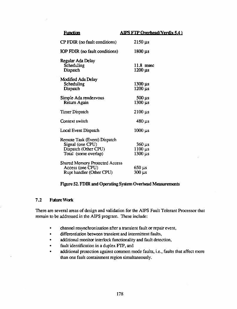
CP FDIR (no fault conditions)
IOP FDIR (no fault conditions)
Regular Ada Delay Scheduling Dispatch
Modified Ada Delay Scheduling Dispatch
Simple Ada rendezvous Return Again
Timer Dispatch
Context switch
Local Event Dispatch
Remote Task (Event) Dispatch Signal (one CPU) Dispatch (Other CPU) Total (some overlap)
Shared Memory Protected Access Access (one CPU) Rupt handler (Other CPU)
2150 ps
1800 ps
11.8 mSec 1200 ps
1300 ps 1200 ps
500 ps
2100 ps
1300 ps
480 ps
lo00 ps
360 ps 1100 ps 1300 ps
650 ps 300 ps
Figure 52. FDIR and Operating System Overhead Measurements
7.2 Futurework
There are several areas of design and validation for the AIPS Fault Tolerant Processor that remain to be addressed in the AIPS program. These include:
channel resynchronization after a transient fault or repair event, differentiation between transient and intermittent faults, additional monitor interlock functionality and fault detection, fault identification in a duplex FI’P, and additional protection against common mode faults, i.e., faults that affect more than one fault containment region simultaneously.
178
7.2.1 Channel ResynchronizatiOn
After a transient fault or repair event, it is necessary to bring the previously faulty channel back into synchronism with the others. To assure identical states, the redundant channels must be synchronized to the instruction level and must have identical values for all volatile hardware control registers, memory and processor registers.
As discussed in Section 4.2.2.2.4, the synchronization of channels to the instruction level is done by an assembly language routine that makes use of the data exchange hardware and fault tolerant clock. In the current implementation, the instructions executed in this routine must take a known number of fault-tolerant clock cycles to be able to synchronize divergent channels. The routine is dependent on the instruction fetch and execution time of the particular microprocessor being used. A way must be found to implement the synchronization routine so that it is independent of the microprocessor instruction times. An algorithm must be developed which can also be rigorously proven to be correct.
A second problem with channel synchronization involves the time required to give all channels identical values for their volatile registers and memory, i.e., to 'align' them. Since AIPS software is very sophisticated and complex, it requires a large amount of memory for static and local variables. Because alignment is accomplished by transferring all values through the data exchange one 32-bit word at a time at a basic rate of 15 ~ s e c per word, and because the entire synchronization process must run uninterrupted, the alignment process takes an unacceptably long time. Critical application tasks m i s s too many cycles. The resynchronization process cannot be omitted because it allows a GPC to sustain more than one fault, thus providing greater reliability.
Several alternatives can be explored to speed up alignment such as an alternative data transfer mechanism (not the present data exchange hardware) or by partitioning memory and only bringing back the critical application task first, or using a hardware memory consistency checker whose purpose is to identify sections of memory which have changed and need to be realigned. The performance and reliability of new fast realignment techniques can then be modeled.
7.2.2 Differentiation Between T d e n t and Intermittent Faults
When recovering a failed channel, system resources are used most efficiently if a distinction is made between transient failures and hard failures. The current design for making this distinction was previously described in Section 4.1.2.1. This design does not account completely, however, for intermittent faults, i.e., hard faults which occur sporadically. The probation concept used in this design will catch intermittent faults which occur at brief intervals (that is, within the probation period) but will not detect intermittent faults which occur at longer intervals (e.g., once every 10 minutes).
179
Two main areas need to be studied in this regard: (1) how do we distinguish between transient and intermittent faults, and (2) how do we treat the intermittent fault once it has been identified.
Intermittent faults may be identified by the periodicity and frequency of their occurrence. For example, a fault occuning once an hour may be arbitrarily designated as transient while one occurring once a minute would be designated as intermittent. History records could be kept, so that a fault which recurred three times within 24 hours might be designated as transient while one which recurred 100 times within this period would be designated as intermittent.
The second area to be studied concerns how an intermittent fault should be treated When a fault is intermittent, is the reliability of the system greater if the channel is taken off line (leaving a less robust GPC) or if the channel is allowed to continue (with the chance of the intermittent fault occurring at the same time as a second fault)? At what point does continually recovering an intermittently faulty channel use more system resources than the additional reliability warrants?
We need to study the relative frequency of transient, intermittent and hard faults. The results of the study will be used to createhpdate Markov models of the AIPS system to include the effects of transient and intermittent faults as well as hard faults. Sensitivity analysis on these models can be performed by varying parameters such as the frequency of an intermittent fault. The results of this analysis will be used to improve the transient analysis algorithm to calculate the appropriate thresholds to use for the transient fault analysis. At present those parameters are guesses.
7.2.3 Additional Monitor Interlodc Functionality and Fault Detedbn
At present, the engage/disengage function of the hardware Monitor Interlock is used to disengage or engage a channel's outputs and the watchdog timer function is used to reset a runaway processor. The Monitor Interlock also has a lock feature which provides more stringent control than does the engage mechanism. Once a faulty channel is locked by the other two channels, it cannot be reset other than by operator intervention. The channel remains locked even if the system is restarted or the power is cycled. This feature is not used presently. A study needs to be done to determine how the use of this feature will affect the reliability of the system and to determine what situations would require using the lock.
A reliable method for detecting latent faults in the monitor interlock is also needed. The monitor interlock is presently tested by comparing the three channels' discrete values. This does not effectively test the hardware, but extensive selftest of this hardware may not be possible in real time. To allow selftests of this hardware in real time, a complicated scheme requiring additional hardware and software must be developed to disengage the entire FTP from the rest of the system. A selftest needs to be developed that will thoroughly test the monitor interlock at preflight and a subset of this test could perhaps be added to the runtime selftes ts.
180

7.2.4 Duplex FTP Fault Isolation and ReconfigUration According to fault tolerance principles, a quadruply redundant FTP can sustain two faults and detect a third, while a triply redundant FI'P can sustain one fault and detect a second with 100% coverage. If a fault occurs in a duplex FI'P, the failure can be detected with 100% coverage but cannot be isolated to one one of the two channels with high coverage. The present redundancy management algorithm simply goes to a fail-safe state by disengaging both channels. However, for those applications where it is not possible to downmode to a fail-safe mode because continued opemtion is absolutely essential, some attempt must be made to isolate the fault, albeit at less than 100% coverage.
There are several hardware features that can be used to develop the desired isolation algorithm. In particular, since the monitor interlock engage/disengage and watchdog timer discretes are available to all channels via point to point connections, these discretes can be accessed even if the channels are not in sync. A lone channel could perform self tests to determine if it was the faulty member of the duplex. If it fails the tests it could disengage itself. If it passes, it would check if the other channel was disengaged. (The coverage of this action is the coverage that can be obtained by selftests running on a simplex processor.) The other channel being disengaged would indicate that that channel was faulty and the lone channel would be able to continue as a simplex. Other algorithms to allow a duplex to degrade to an operational simplex need to be studied.
7.2.5 Common Mode Fault Protection
At present Local System Services provides a restartheinitialization of the FTP as a protection for common mode faults, i.e., faults that affect more than one fault containment region simultaneously or almost simultaneously. Since all the manifestations or the emrs generated from common mode faults are not known, the restart only protects the FI'P when the error symptoms are the following: hardware exception, operating system software exception, desynchronization of channels, or watchdog timer reset.
Further work needs to be done to identify and categorize other potential sources of common mode faults and potential errors generated by those faults. Additional fault avoidance techniques such as proof-of-correctness and alternative recovery techniques such as function migration, software watchdog timers and multiversion software should be studied for practicality and effectiveness.

8.0 REFERENCES
1. T. B. Smith, 111, “Fault Tolerant Processor Concepts and Operation”, 14th International Symposium on Fault Tolerant Computing, Orlando, Florida, June, 1984.
2. J. H. Lala, “A Byzantine Resilient Fault-Tolerant Computer for Nuclear Power Plant Applications”, 16th International Symposium on Fault Tolerant Computing, Vienna, Austria, July, 1986.
3. T. Massotto and L. Alger, “Advanced Information Processing System: InpuVOutput System Services”, to be published.
4. G. Nagle, L. Alger and A. Kemp, “Advanced Information Processing System: Input/Output Network Management Software”, NASA Contractor Report 18 1678, May, 1988.
IIRECU)ING PAGE BLANK NOT NLMED
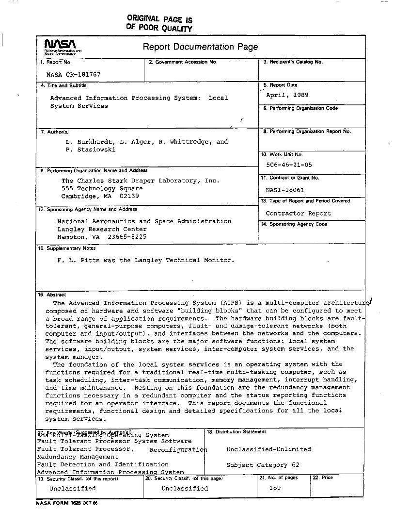
ORIGINAL PAGE IS OF POOR QUALW
1. Report No.
NASA CR-181767
Report Documentation Page 2. Government Accession No.
, 7 d ~ e l C 1 ~ ~ I ~ ~ i ~ F P V ~ E ~ ~ ~ n g System 'ault Tolerant Processor System Software 'ault Tolerant PrOCeSSOr, Reconfiguratio? edundancy Management ault Detection and Identification dvanced Information Processins System
I
4. Title and Subtitle
18. Distribution Statement
Unclassified-Unlimited
Subject Category 62
Advanced Information Processing System: Local System Services
8. Security Classif. (of this report) 20 Security Classif. (of this page) 21. No. of pages
Unclassified Unclassified 189
f
7. Authorkl
L. Burkhardt, L. Alger, R. Whittredge, and P. Stasiowski
22. Price
9. Performing Organization Name and Address
The Charles Stark Draper Laboratory, Inc. 555 Technology Square Cambridge, MA 02139
12. Sponsoring Agency Name and Address
National Aeronautics and Space Administration Langley Research Center Hampton, VA 23665-5225
5. Supplementary Notes
F. L. Pitts was the Langley Technical Monitor.
3. Recipient's Catalog No.
5. Report Date /
April, 1989
6. Performing Organization Code
8. Performing Organization Report No.
10. Work Unit No.
506-46-21-05
11. Contract or Grant No.
NAS1-18061 13. Type of Repon and Period Covered
Contractor Report 14. Sponsoring egency Code