LF1000 - TECHNICAL INFORMATION
30
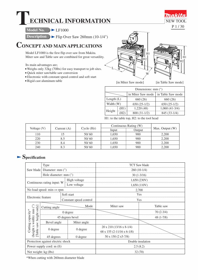
Model No. Description NEW TOOL CONCEPT AND MAIN APPLICATIONS Specification P 1 / 30 Flip Over Saw 260mm (10-1/4") Model LF1000 is the first flip over saw from Makita. Miter saw and Table saw are combined for great versatility. Its main advantages are; Weighs only 32kg (70lbs) for easy transport to job sites. Quick miter saw/table saw conversion Electronic with constant speed control and soft start Rigid cast aluminum table LF1000 Saw blade Electronic feature Protection against electric shock Power supply cord: m (ft) Net weight: kg (lbs) *When cutting with 260mm diameter blade Mode Miter saw Table saw No load speed: min-1= rpm Continuous rating input: W Type Diameter: mm (") Hole diameter: mm (") Dimensions: mm (") Width (W) (H1) Height Length (L) in Miter Saw mode in Table Saw mode 660 (26) 660 (26) 650 (25-1/2) 650 (25-1/2) 1,220 (48) 1,060 (41-3/4) (H2) 800 (31-1/2) 845 (33-1/4) High voltage Low voltage Soft start Constant speed control 0 degree 45 degrees bevel 0 degree 0 degree 45 degrees Miter angle Bevel angle 0 degree 70 (2-3/4) 20 x 210 (13/16 x 8-1/4) 68 x 155 (2-11/16 x 6-1/8) 50 x 150 (2 x5-7/8) Double insulation TCT Saw blade 260 (10-1/4) 30 (1-3/16) 1,650 (230V) 1,650 (110V) 2,700 Yes Yes 2.5 (8.2) 32 (70) 48 (1-7/8) Cutting angle H2 H2 W L [in Miter Saw mode] [in Table Saw mode] H1: to the table top, H2: to the tool head T ECHNICAL INFORMATION H1 H1 Continuous Rating (W) Voltage (V) Cycle (Hz) Input Output Max. Output (W) 110 220 230 240 15 8.5 8.4 8.3 50/ 60 50/ 60 50/ 60 50/ 60 1,650 1,650 1,650 1,650 900 900 900 900 2,200 2,200 2,200 2,200 Current (A) Cutting capacity* (height x width): mm (") [Table saw: height only]
-
Upload
khangminh22 -
Category
Documents
-
view
3 -
download
0
Transcript of LF1000 - TECHNICAL INFORMATION
Model No.
Description
NEW TOOL
CONCEPT AND MAIN APPLICATIONS
Specification
P 1 / 30
Flip Over Saw 260mm (10-1/4")
Model LF1000 is the first flip over saw from Makita.Miter saw and Table saw are combined for great versatility.
Its main advantages are; Weighs only 32kg (70lbs) for easy transport to job sites. Quick miter saw/table saw conversion Electronic with constant speed control and soft start Rigid cast aluminum table
LF1000
Saw blade
Electronic feature
Protection against electric shock
Power supply cord: m (ft)
Net weight: kg (lbs)
*When cutting with 260mm diameter blade
Mode Miter saw Table saw
No load speed: min-1= rpm
Continuous rating input: W
Type
Diameter: mm (")
Hole diameter: mm (")
Dimensions: mm (")
Width (W)(H1)
Height
Length (L)
in Miter Saw mode in Table Saw mode
660 (26) 660 (26)
650 (25-1/2) 650 (25-1/2)1,220 (48) 1,060 (41-3/4)
(H2) 800 (31-1/2) 845 (33-1/4)
High voltage
Low voltage
Soft start
Constant speed control
0 degree
45 degrees bevel
0 degree 0 degree
45 degrees
Miter angleBevel angle
0 degree
70 (2-3/4)
20 x 210 (13/16 x 8-1/4)
68 x 155 (2-11/16 x 6-1/8)
50 x 150 (2 x5-7/8)
Double insulation
TCT Saw blade
260 (10-1/4)
30 (1-3/16)
1,650 (230V)
1,650 (110V)
2,700Yes
Yes
2.5 (8.2)
32 (70)
48 (1-7/8)
Cutting angle
H2H2
W
L
[in Miter Saw mode] [in Table Saw mode]
H1: to the table top, H2: to the tool head
TECHNICAL INFORMATION
H1H1
Continuous Rating (W)Voltage (V) Cycle (Hz) Input Output Max. Output (W)
110220230240
158.58.48.3
50/ 6050/ 6050/ 6050/ 60
1,6501,6501,6501,650
900900900900
2,2002,2002,2002,200
Current (A)
Cut
ting
capa
city
*(h
eigh
t x w
idth
): m
m (
")[T
able
saw
: hei
ght o
nly]

P 2 / 30
Standard equipment
Assorted TCT saw blades
Note: The standard equipment for the tool shown above may differ by country.
TCT saw blade ......... 1 pcVise ass'y ................. 1 pcDust bag ass'y .......... 1 pcRuler ass'y ................ 1 pc
Box wrench 13-3 ...... 1 pcPush stick ................. 1 pcFix plate ................... 3 pcsHex bolt M6x16 ....... 3 pcs
Triangular rule ........ 1 pcAngle rule ass'y ....... 1 pcTop cover ass'y ....... 1 pcDust cover ass'y ...... 1 pcElbow ..................... 1 pc
Optional accessories

P 3 / 30
Repair
[1] NECESSARY REPAIRING TOOLS
CAUTION: Remove the saw blade from the machine for safety before repair/ maintenance !
Code No.
1R003 Retaining ring S Pliers ST-2N Removing Retaining ring from Safety cover
1R207 45 degree Set square Setting the miter/bevel angle of saw blade to 45 degrees
1R208 90 degree Set square Setting the miter/bevel angle of saw blade to 90 degrees
1R269 Bearing extractor Removing Ball bearings
1R288 Screwdriver magnetizer Removing Steel balls, etc.
1R230 1/4" Hex shank bit for M6 Disassembling Table
1R231 1/4" Hex shank bit for M8 Disassembling Frame
1R291 Retaining ring S and R pliers Removing Retaining ring S-15 from Spindle
1R340 Wrench for bearing retainer Removing/tightening Bearing retainer 25-36
Description
Square
No.3 Philips driver bitRemoving/tightening of M6x60 Pan head screws that secureMotor housing to Blade case.
Assembling the legs of table
Use for
[2] LUBRICATION
Apply Makita grease N. No.1 to the following portions designated with the black triangle to protectparts and product from unusual abrasion. See Fig. 1.
[2] -1. Saw Head Section
121
121
61
64
91
85
85
50
50 Hex bolt M10Knob 40Steel ball 6
The surface that contacts Arm completeThe threaded portionWhole surface62
Sleeve 6 The surface that contacts Connecting rod64Sleeve 10 The surface that contacts Adjust nut
Flat washer 10 The surface that contacts Connecting rod
71
Sub arm
Blade caseThe gear room (Put approx. 7g.)Two surfaces that contact Arm complete
Three surfaces that contacts Arm complete91
Connecting rod
Arm complete
Item No. Description Portion to lubricate
Adjust nut
Sleeve 13
61
71
62
Fig. 1
P 4 / 30
Repair
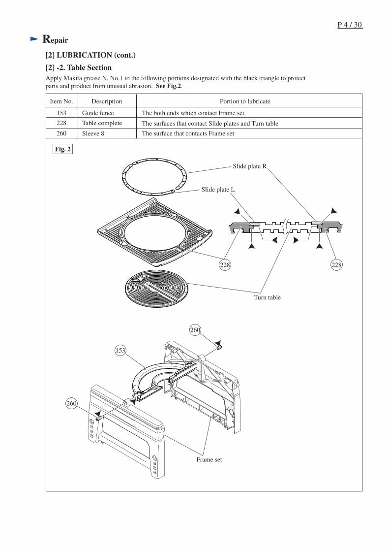
[2] LUBRICATION (cont.)
Apply Makita grease N. No.1 to the following portions designated with the black triangle to protectparts and product from unusual abrasion. See Fig.2.
Slide plate L
Table complete
Turn table
Slide plate R
153
153 Guide fence
228
Sleeve 8260
The both ends which contact Frame set.
The surface that contacts Frame set
The surfaces that contact Slide plates and Turn table
260
Frame set
Fig. 2
Item No. Description Portion to lubricate
260
228
[2] -2. Table Section
228
P 5 / 30
Repair
[3] DISASSEMBLY/ASSEMBLY
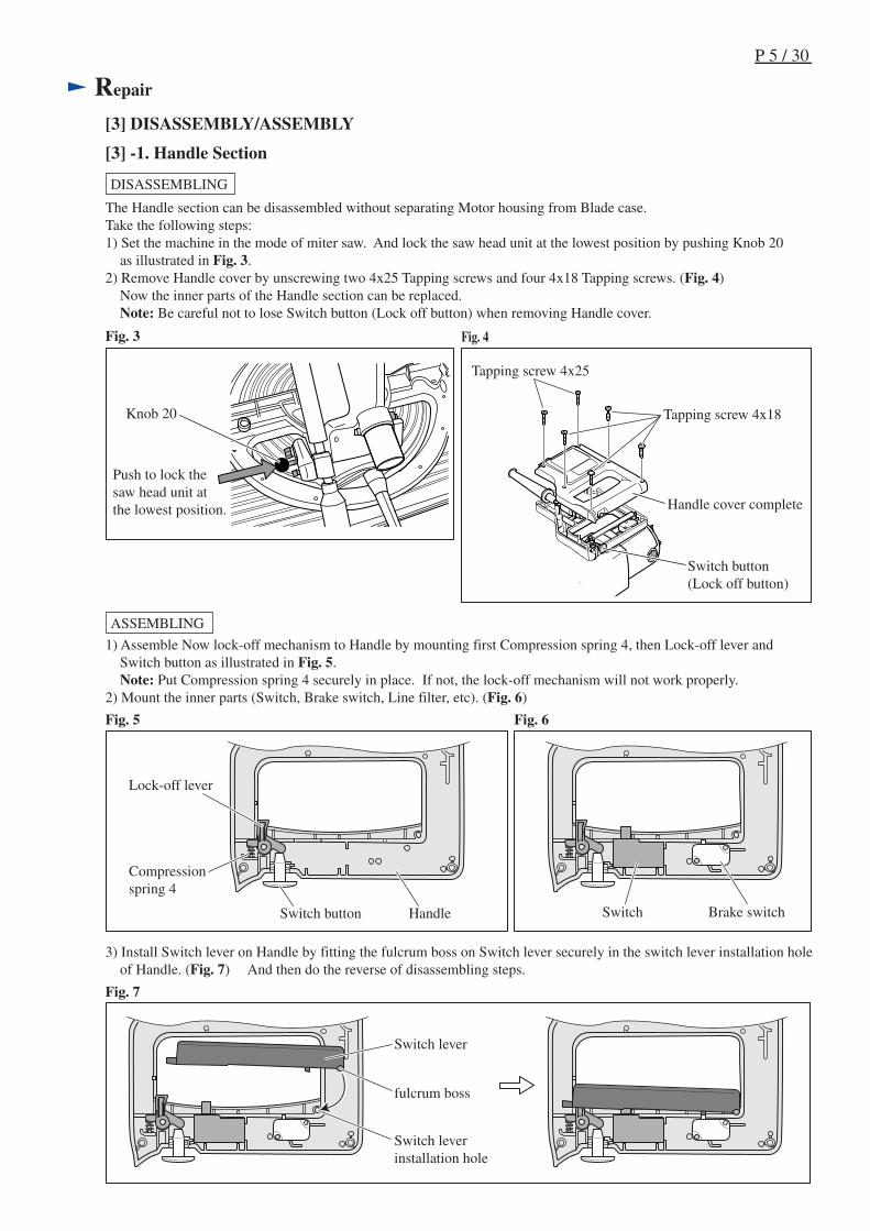
[3] -1. Handle Section
Fig. 4Fig. 3
Fig. 5
DISASSEMBLING
The Handle section can be disassembled without separating Motor housing from Blade case.Take the following steps:1) Set the machine in the mode of miter saw. And lock the saw head unit at the lowest position by pushing Knob 20 as illustrated in Fig. 3.2) Remove Handle cover by unscrewing two 4x25 Tapping screws and four 4x18 Tapping screws. (Fig. 4) Now the inner parts of the Handle section can be replaced. Note: Be careful not to lose Switch button (Lock off button) when removing Handle cover.
Knob 20
Push to lock thesaw head unit atthe lowest position.
Switch button(Lock off button)
Handle cover complete
Tapping screw 4x25
Tapping screw 4x18
ASSEMBLING
1) Assemble Now lock-off mechanism to Handle by mounting first Compression spring 4, then Lock-off lever and Switch button as illustrated in Fig. 5. Note: Put Compression spring 4 securely in place. If not, the lock-off mechanism will not work properly.2) Mount the inner parts (Switch, Brake switch, Line filter, etc). (Fig. 6)
Compressionspring 4
Lock-off lever
Switch button
Fig. 6
3) Install Switch lever on Handle by fitting the fulcrum boss on Switch lever securely in the switch lever installation hole of Handle. (Fig. 7) And then do the reverse of disassembling steps.
Fig. 7
fulcrum boss
Switch lever
Switch leverinstallation hole
Handle Switch Brake switch
P 6 / 30
Repair
[3] DISASSEMBLY/ASSEMBLY
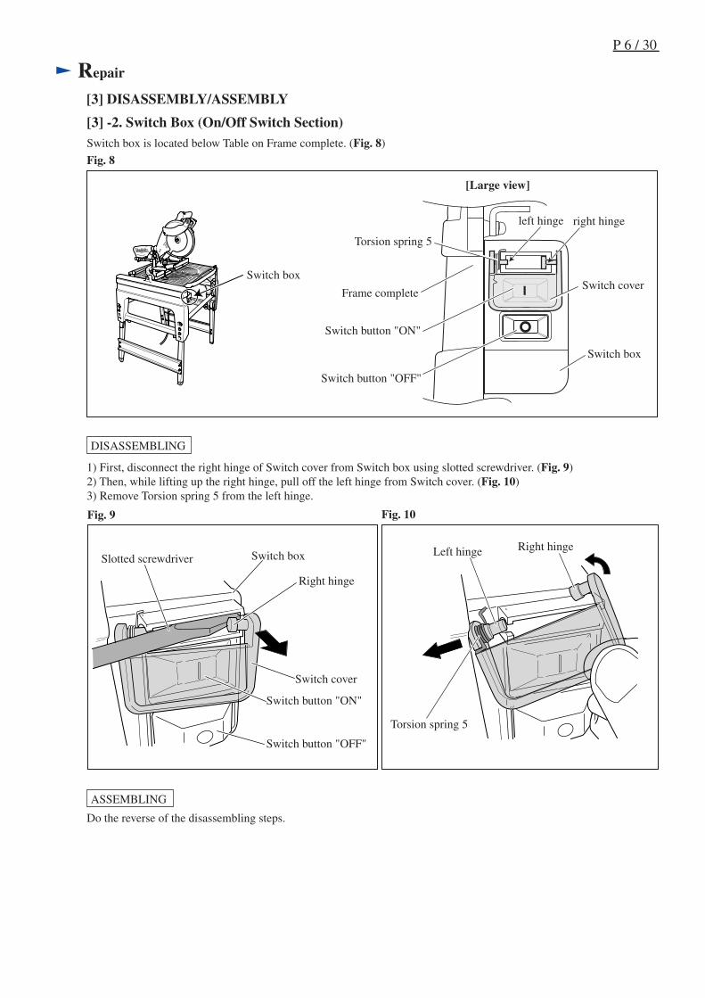
DISASSEMBLING
ASSEMBLING
[3] -2. Switch Box (On/Off Switch Section)
Do the reverse of the disassembling steps.
Fig. 10Fig. 9
1) First, disconnect the right hinge of Switch cover from Switch box using slotted screwdriver. (Fig. 9)2) Then, while lifting up the right hinge, pull off the left hinge from Switch cover. (Fig. 10)3) Remove Torsion spring 5 from the left hinge.
Switch box is located below Table on Frame complete. (Fig. 8)
Right hingeLeft hinge
Torsion spring 5
Switch cover
Switch boxSlotted screwdriver
Switch button "ON"
Switch button "OFF"
Right hinge
Fig. 8
Switch button "ON"
Switch button "OFF"
Torsion spring 5
Switch cover
Switch box
Frame complete
left hinge right hinge
Switch box
[Large view]
P 7 / 30
Repair
[3] DISASSEMBLY/ASSEMBLY
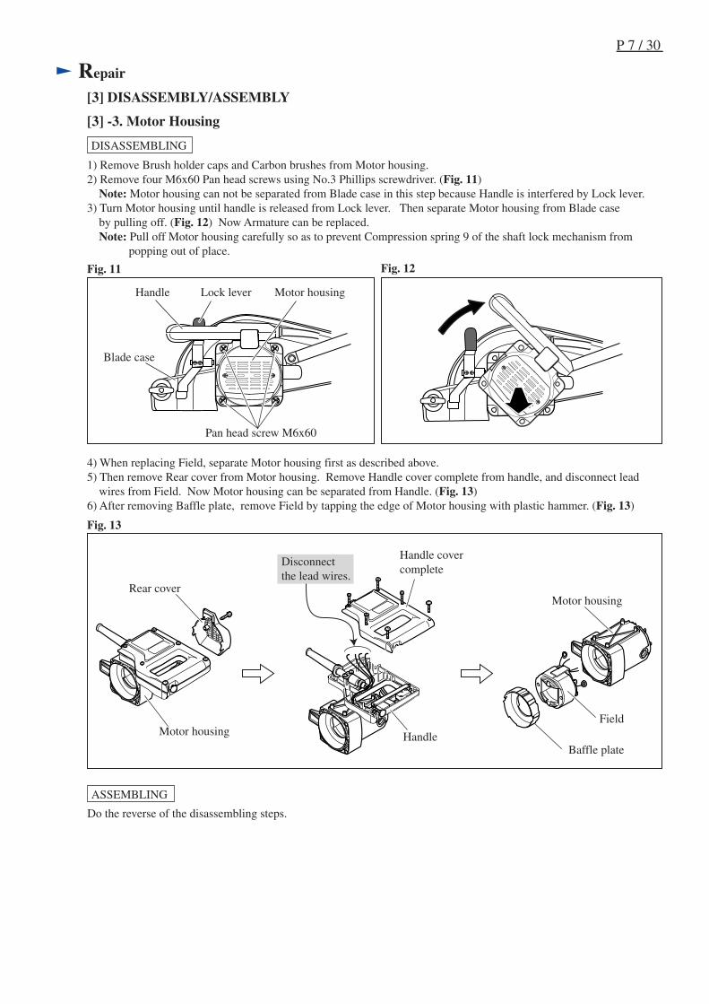
[3] -3. Motor Housing
Fig. 12
Fig. 13
DISASSEMBLING
Fig. 11
Motor housing
1) Remove Brush holder caps and Carbon brushes from Motor housing.2) Remove four M6x60 Pan head screws using No.3 Phillips screwdriver. (Fig. 11) Note: Motor housing can not be separated from Blade case in this step because Handle is interfered by Lock lever.3) Turn Motor housing until handle is released from Lock lever. Then separate Motor housing from Blade case by pulling off. (Fig. 12) Now Armature can be replaced. Note: Pull off Motor housing carefully so as to prevent Compression spring 9 of the shaft lock mechanism from popping out of place.
Pan head screw M6x60
Lock leverHandle
4) When replacing Field, separate Motor housing first as described above.5) Then remove Rear cover from Motor housing. Remove Handle cover complete from handle, and disconnect lead wires from Field. Now Motor housing can be separated from Handle. (Fig. 13)6) After removing Baffle plate, remove Field by tapping the edge of Motor housing with plastic hammer. (Fig. 13)
Rear cover
Baffle plate
Motor housing
Field
Handle covercomplete
Handle
Blade case
Motor housing
Disconnectthe lead wires.
ASSEMBLING
Do the reverse of the disassembling steps.
P 8 / 30
Repair
[3] DISASSEMBLY/ASSEMBLY
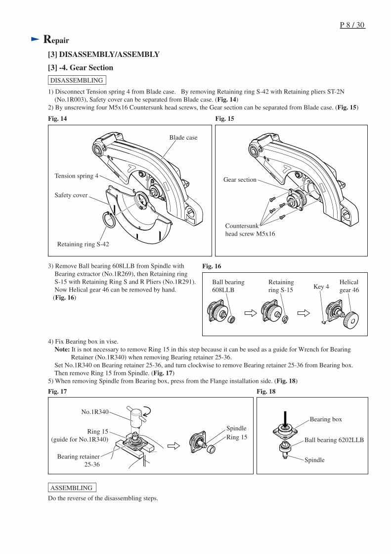
[3] -4. Gear Section
Fig. 17
Fig. 15
Fig. 18
DISASSEMBLING
Fig. 14
1) Disconnect Tension spring 4 from Blade case. By removing Retaining ring S-42 with Retaining pliers ST-2N (No.1R003), Safety cover can be separated from Blade case. (Fig. 14)2) By unscrewing four M5x16 Countersunk head screws, the Gear section can be separated from Blade case. (Fig. 15)
3) Remove Ball bearing 608LLB from Spindle with Bearing extractor (No.1R269), then Retaining ring S-15 with Retaining Ring S and R Pliers (No.1R291). Now Helical gear 46 can be removed by hand. (Fig. 16)
4) Fix Bearing box in vise. Note: It is not necessary to remove Ring 15 in this step because it can be used as a guide for Wrench for Bearing Retainer (No.1R340) when removing Bearing retainer 25-36. Set No.1R340 on Bearing retainer 25-36, and turn clockwise to remove Bearing retainer 25-36 from Bearing box. Then remove Ring 15 from Spindle. (Fig. 17)5) When removing Spindle from Bearing box, press from the Flange installation side. (Fig. 18)
Retaining ring S-42
Safety cover
Tension spring 4
Countersunkhead screw M5x16
Gear section
No.1R340
Ring 15(guide for No.1R340) Ring 15
Spindle
Bearing retainer25-36
ASSEMBLING
Do the reverse of the disassembling steps.
Blade case
Ball bearing 6202LLB
Spindle
Bearing box
Fig. 16
Ball bearing608LLB
Retainingring S-15
Helicalgear 46Key 4
P 9 / 30
Repair
[3] DISASSEMBLY/ASSEMBLY
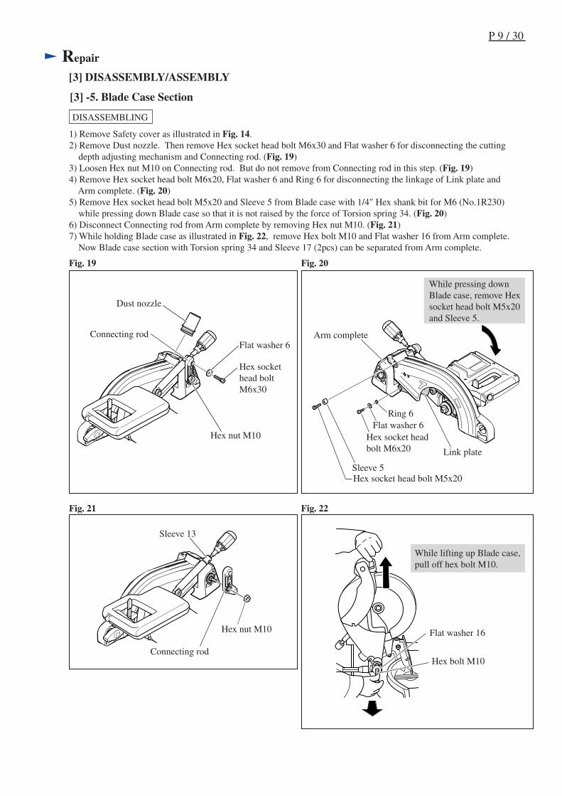
[3] -5. Blade Case Section
Fig. 21 Fig. 22
DISASSEMBLING
Fig. 19 Fig. 20
1) Remove Safety cover as illustrated in Fig. 14.2) Remove Dust nozzle. Then remove Hex socket head bolt M6x30 and Flat washer 6 for disconnecting the cutting depth adjusting mechanism and Connecting rod. (Fig. 19)3) Loosen Hex nut M10 on Connecting rod. But do not remove from Connecting rod in this step. (Fig. 19)4) Remove Hex socket head bolt M6x20, Flat washer 6 and Ring 6 for disconnecting the linkage of Link plate and Arm complete. (Fig. 20)5) Remove Hex socket head bolt M5x20 and Sleeve 5 from Blade case with 1/4" Hex shank bit for M6 (No.1R230) while pressing down Blade case so that it is not raised by the force of Torsion spring 34. (Fig. 20)6) Disconnect Connecting rod from Arm complete by removing Hex nut M10. (Fig. 21)7) While holding Blade case as illustrated in Fig. 22, remove Hex bolt M10 and Flat washer 16 from Arm complete. Now Blade case section with Torsion spring 34 and Sleeve 17 (2pcs) can be separated from Arm complete.
Hex socket head boltM6x30
Hex socket headbolt M6x20
Flat washer 6
Sleeve 5Hex socket head bolt M5x20
Flat washer 6 Ring 6
Link plate
Arm complete
While pressing downBlade case, remove Hexsocket head bolt M5x20and Sleeve 5.
Dust nozzle
Hex nut M10
Connecting rod
Hex nut M10
Sleeve 13
Connecting rodHex bolt M10
Flat washer 16
While lifting up Blade case,pull off hex bolt M10.

P 10/ 30
Repair
[3] DISASSEMBLY/ASSEMBLY
Fig. 23
Fig. 24 Fig. 25
ASSEMBLING
[3] -5. Blade Case Section (cont.)
Slide Sleeve 13 as far as possible toward Steel ball 6. At this time, the distance between Sleeve 13 and the neck ofKnob 40 will be about 7mm. While keeping the distance, secure Connecting rod to Sleeve 13 with Hex socket head boltM6x30. (Fig. 23)
1. When installing Sleeve 13 and Connecting rod on Knob 40;
2. When installing Link plate and Safety cover on Blade case;
Do the reverse step of disassembling steps. Remember the following notes.
Steel ball 6on Knob 40
Sleeve 13
Adjust nut
Knob 40
7mm
Sleeve 6
Connecting rod
Flat washer 6
Hex socket headbolt M6x30
Blade case
As illustrated in Fig. 24, put Link plate on Ball bearing 608LLB that is mounted to the inside wall of Blade case forsmooth action of Link plate. Then secure Link plate to Arm complete with Hex socket head bolt M6x20. (Fig. 20)On the back of Safety cover, there is a rib that acts as a guide rail for the Ball bearing on Link plate.Mount Safety cover to Bearing box so that the Ball bearing of Link plate fits on the rib. (Fig. 25) And secure Safety cover with Retaining ring S-42. (Fig. 14)
Rib
Ball bearing of Link plate Tension spring 4
Tension spring 4
Ball bearing608LLB
Ball bearing(integral part of Link plate)
Link plate
Rib
Safety cover and Link plate correctly set in place,viewed from the Motor housing side
Link plate
Blade case
Safety cover
Safety cover
P 11/ 30
Repair
[3] DISASSEMBLY/ASSEMBLY
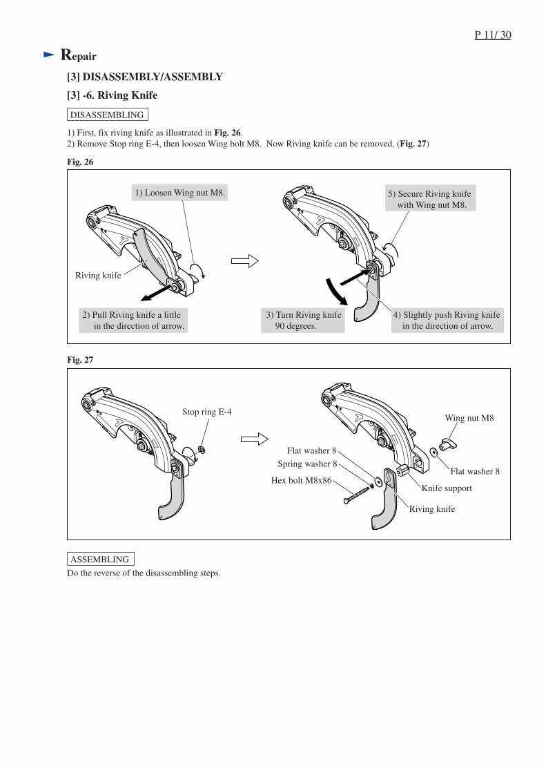
[3] -6. Riving Knife
Fig. 27
Fig. 26
DISASSEMBLING
1) Loosen Wing nut M8.
1) First, fix riving knife as illustrated in Fig. 26.2) Remove Stop ring E-4, then loosen Wing bolt M8. Now Riving knife can be removed. (Fig. 27)
2) Pull Riving knife a little in the direction of arrow.
3) Turn Riving knife 90 degrees.
4) Slightly push Riving knife in the direction of arrow.
5) Secure Riving knife with Wing nut M8.
Stop ring E-4
Do the reverse of the disassembling steps.
Hex bolt M8x86
Spring washer 8
Flat washer 8
Flat washer 8
Riving knife
Knife support
Wing nut M8
ASSEMBLING
Riving knife
P 12/ 30
Repair
[3] DISASSEMBLY/ASSEMBLY
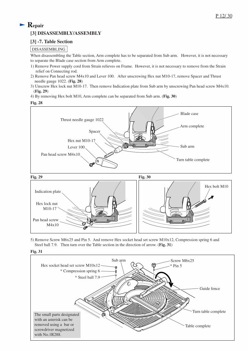
[3] -7. Table Section
Fig. 29 Fig. 30
Fig. 28
DISASSEMBLING
Pan head screw M4x10
Pan head screwM4x10
Thrust needle gauge 1022
Lever 100
Hex nut M10-17
SpacerArm complete
When disassembling the Table section, Arm complete has to be separated from Sub arm. However, it is not necessaryto separate the Blade case section from Arm complete.1) Remove Power supply cord from Strain relieves on Frame. However, it is not necessary to remove from the Strain relief on Connecting rod. 2) Remove Pan head screw M4x10 and Lever 100. After unscrewing Hex nut M10-17, remove Spacer and Thrust needle gauge 1022. (Fig. 28)3) Unscrew Hex lock nut M10-17. Then remove Indication plate from Sub arm by unscrewing Pan head screw M4x10. (Fig. 29)4) By removing Hex bolt M10, Arm complete can be separated from Sub arm. (Fig. 30)
Sub arm
Turn table complete
Hex lock nutM10-17
Indication plateHex bolt M10
Blade case
Fig. 31
Screw M6x25
Guide fence
Turn table complete
Hex socket head set screw M10x12* Compression spring 6
* Steel ball 7.9
* Pin 5Sub arm
Table complete
The small parts designatedwith an asterisk can beremoved using a bar orscrewdriver magnetizedwith No.1R288.
5) Remove Screw M6x25 and Pin 5. And remove Hex socket head set screw M10x12, Compression spring 6 and Steel ball 7.9. Then turn over the Table section in the direction of arrow. (Fig. 31)
P 13/ 30
Repair
[3] DISASSEMBLY/ASSEMBLY
DISASSEMBLING
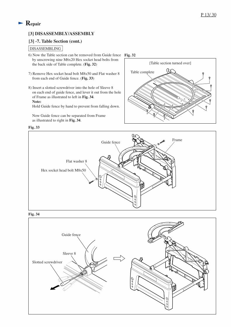
[3] -7. Table Section (cont.)
Fig. 33
Fig. 34
6) Now the Table section can be removed from Guide fence by unscrewing nine M6x20 Hex socket head bolts from the back side of Table complete. (Fig. 32)
7) Remove Hex socket head bolt M8x50 and Flat washer 8 from each end of Guide fence. (Fig. 33)
8) Insert a slotted screwdriver into the hole of Sleeve 8 on each end of guide fence, and lever it out from the hole of Frame as illustrated to left in Fig. 34. Note: Hold Guide fence by hand to prevent from falling down. Now Guide fence can be separated from Frame as illustrated to right in Fig. 34.
Fig. 32
[Table section turned over]
Table complete
Hex socket head bolt M8x50
Flat washer 8
Frame
Guide fence
Slotted screwdriver
Sleeve 8
Guide fence

P 14/ 30
Repair
[3] DISASSEMBLY/ASSEMBLY
DISASSEMBLING
[3] -7. Table Section (cont.)
Fig. 35
9) Lever (Lock lever) is fastened to Frame with each two pieces of Hex socket button head bolt M6 and Flat washer 7. When removing Lever, follow the instruction described in Fig. 35.
Hex socketbutton headbolt M6
Lever
Flat washer 7
Torsion spring 17
Boss for Torsion spring installation
ASSEMBLING
Do the reverse of the disassembling steps 1) - 9).Note:When installing Torsion spring 17 on Frame, insert the springstraight over the boss till it touches the inside wall of Frame.Be careful not to tilt the spring. (Fig. 36)
Frame
Boss for Torsionspring installation
Torsion spring 17
Fig. 36
Frame
Lever
If this bolt is removed first, the force of Torsion springwill cause the Bolt and Flat washer 7 to pop off.
Be sure to remove this bolt firstfor easy removal of Lever.
P 15/ 30
Repair
[3] DISASSEMBLY/ASSEMBLY
[3] -8. Frame Section
Fig. 37
Fig. 39
Fig. 38
Fig. 40
DISASSEMBLING
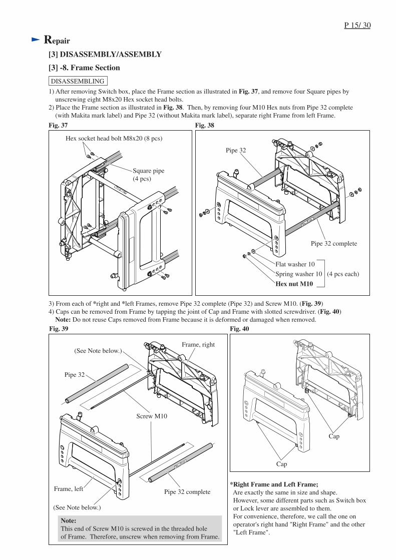
1) After removing Switch box, place the Frame section as illustrated in Fig. 37, and remove four Square pipes by unscrewing eight M8x20 Hex socket head bolts.2) Place the Frame section as illustrated in Fig. 38. Then, by removing four M10 Hex nuts from Pipe 32 complete (with Makita mark label) and Pipe 32 (without Makita mark label), separate right Frame from left Frame.
Hex socket head bolt M8x20 (8 pcs)
Square pipe(4 pcs)
3) From each of *right and *left Frames, remove Pipe 32 complete (Pipe 32) and Screw M10. (Fig. 39)4) Caps can be removed from Frame by tapping the joint of Cap and Frame with slotted screwdriver. (Fig. 40) Note: Do not reuse Caps removed from Frame because it is deformed or damaged when removed.
Pipe 32
Pipe 32 complete
Screw M10
Cap
Hex nut M10
Spring washer 10
Flat washer 10
Pipe 32 complete
(4 pcs each)
Frame, right
Frame, left
Pipe 32
Note:This end of Screw M10 is screwed in the threaded holeof Frame. Therefore, unscrew when removing from Frame.
Cap
(See Note below.)
(See Note below.)
*Right Frame and Left Frame; Are exactly the same in size and shape. However, some different parts such as Switch box or Lock lever are assembled to them. For convenience, therefore, we call the one on operator's right hand "Right Frame" and the other "Left Frame".
P 16/ 30
Repair
[3] DISASSEMBLY/ASSEMBLY
[3] -8. Frame Section (cont.)
ASSEMBLING
Fig. 41
Fig. 42 Fig. 43
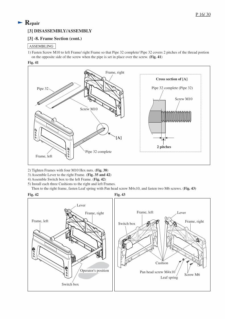
1) Fasten Screw M10 to left Frame/ right Frame so that Pipe 32 complete/ Pipe 32 covers 2 pitches of the thread portion on the opposite side of the screw when the pipe is set in place over the screw. (Fig. 41)
2) Tighten Frames with four M10 Hex nuts. (Fig. 38) 3) Assemble Lever to the right Frame. (Fig. 35 and 42)4) Assemble Switch box to the left Frame. (Fig. 42)5) Install each three Cushions to the right and left Frames. Then to the right frame, fasten Leaf spring with Pan head screw M4x10, and fasten two M6 screws. (Fig. 43)
Operator's position
Switch box
Lever
Frame, left
Frame, right Lever
Switch box
Frame, left
Frame, right
Cushion
Leaf springScrew M6
Pan head screw M4x10
Pipe 32
Pipe 32 complete
Screw M10
Frame, right
Frame, left
Pipe 32 complete (Pipe 32)
Screw M10
2 pitches
[A]
Cross section of [A]
Hex bolt M6x45
Flat washer 6
P 17/ 30
Repair
[3] DISASSEMBLY/ASSEMBLY
[3] -9. Assembling Feet Section
Fig. 44 Fig. 45
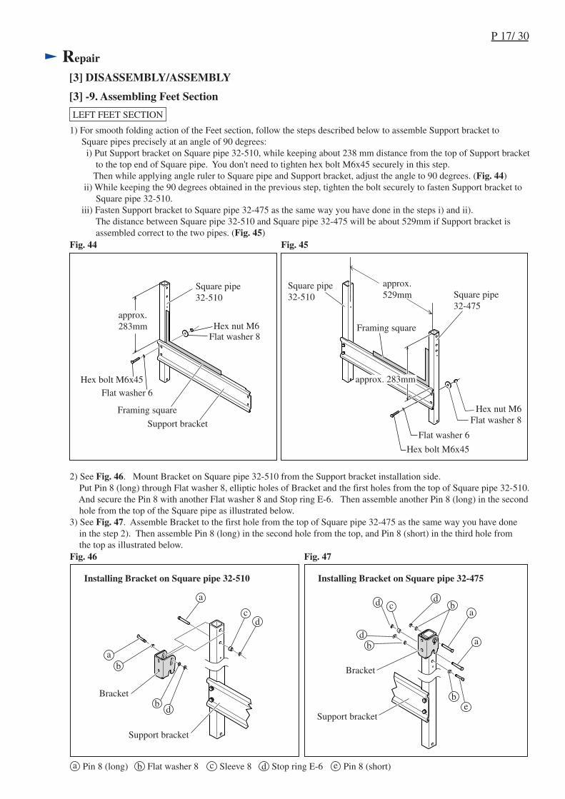
1) For smooth folding action of the Feet section, follow the steps described below to assemble Support bracket to Square pipes precisely at an angle of 90 degrees: i) Put Support bracket on Square pipe 32-510, while keeping about 238 mm distance from the top of Support bracket to the top end of Square pipe. You don't need to tighten hex bolt M6x45 securely in this step. Then while applying angle ruler to Square pipe and Support bracket, adjust the angle to 90 degrees. (Fig. 44) ii) While keeping the 90 degrees obtained in the previous step, tighten the bolt securely to fasten Support bracket to Square pipe 32-510. iii) Fasten Support bracket to Square pipe 32-475 as the same way you have done in the steps i) and ii). The distance between Square pipe 32-510 and Square pipe 32-475 will be about 529mm if Support bracket is assembled correct to the two pipes. (Fig. 45)
LEFT FEET SECTION
Hex bolt M6x45Flat washer 6
Flat washer 8Hex nut M6
Flat washer 8Hex nut M6Framing square
Framing square
Square pipe32-510 Square pipe
32-475
Support bracket
approx.283mm
approx.529mm
approx. 283mm
Square pipe32-510
2) See Fig. 46. Mount Bracket on Square pipe 32-510 from the Support bracket installation side. Put Pin 8 (long) through Flat washer 8, elliptic holes of Bracket and the first holes from the top of Square pipe 32-510. And secure the Pin 8 with another Flat washer 8 and Stop ring E-6. Then assemble another Pin 8 (long) in the second hole from the top of the Square pipe as illustrated below.3) See Fig. 47. Assemble Bracket to the first hole from the top of Square pipe 32-475 as the same way you have done in the step 2). Then assemble Pin 8 (long) in the second hole from the top, and Pin 8 (short) in the third hole from the top as illustrated below.
Bracket
Bracket
Support bracket
Fig. 46 Fig. 47
Installing Bracket on Square pipe 32-510 Installing Bracket on Square pipe 32-475
Support bracket
Pin 8 (long) Pin 8 (short)Flat washer 8 Sleeve 8 Stop ring E-6

P 18/ 30
Repair
[3] DISASSEMBLY/ASSEMBLY
[3] -9. Assembling Feet Section (cont.)
Fig. 48
4) To Square pipe 32-510, assemble Hook and Foot. And to Square pipe 32-475, assemble Stopper hook and Foot nut. (Fig. 48)
LEFT FEET SECTION
Stopper hookHook
Square pipe 32-510
Hex nut M6
Foot
Foot
Foot bolt
Compression spring 13
Foot nut
Foot nut
Square pipe 32-475
Stopper hook
Pin 8 (long)Pin 8 (short)
Foot
Support bracket
Fig. 49
Note: Different from the Left feet section, two 32-475 Square pipes are used for the right Feet section.1) The same way as you did in assembling the left feet section; Assemble Support bracket to Square pipes precisely at an angle of 90 degrees. (Fig. 45, 46) Then assemble Bracket and Pin 8 to each Square pipe. (Fig. 47, 48)2) Assemble Stopper hook to the Square pipe 32-475 on the side of operator's position. (Fig. 49)3) Mount Foot to each Square pipe. (Fig. 49)
RIGHT FEET SECTION
Support bracket
Hex nut M6
Foot
Pin 8 (long)
Bracket
P 19/ 30
Repair
[3] DISASSEMBLY/ASSEMBLY
[3] -10. Assembling Feet Section to Frame Section
Fig. 50
Fig. 51
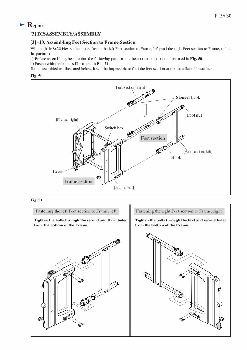
With eight M8x20 Hex socket bolts, fasten the left Feet section to Frame, left; and the right Feet section to Frame, right.Important:a) Before assembling, be sure that the following parts are in the correct position as illustrated in Fig. 50.b) Fasten with the bolts as illustrated in Fig. 51.If not assembled as illustrated below, it will be impossible to fold the feet section or obtain a flat table surface.
Foot nut
Hook
Frame section
Stopper hook
Feet section
[Frame, left]
Lever
Switch box
[Frame, right]
[Feet section, right]
[Feet section, left]
Tighten the bolts through the second and third holesfrom the bottom of the Frame.
Tighten the bolts through the first and second holesfrom the bottom of the Frame.
Fastening the left Feet section to Frame, left Fastening the right Feet section to Frame, right
P 20/ 30
Repair
[4] ADJUSTMENT
[4] -1. Adjusting Bevel Angle
Fig. 52 Fig. 53
Fig. 54 Fig. 55
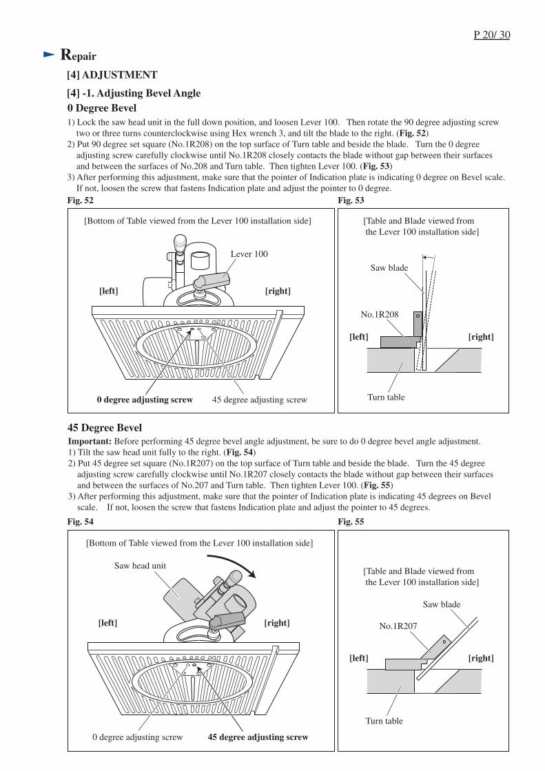
1) Lock the saw head unit in the full down position, and loosen Lever 100. Then rotate the 90 degree adjusting screw two or three turns counterclockwise using Hex wrench 3, and tilt the blade to the right. (Fig. 52)2) Put 90 degree set square (No.1R208) on the top surface of Turn table and beside the blade. Turn the 0 degree adjusting screw carefully clockwise until No.1R208 closely contacts the blade without gap between their surfaces and between the surfaces of No.208 and Turn table. Then tighten Lever 100. (Fig. 53)3) After performing this adjustment, make sure that the pointer of Indication plate is indicating 0 degree on Bevel scale. If not, loosen the screw that fastens Indication plate and adjust the pointer to 0 degree.
[Bottom of Table viewed from the Lever 100 installation side] [Table and Blade viewed from the Lever 100 installation side]
[Bottom of Table viewed from the Lever 100 installation side]
[Table and Blade viewed from the Lever 100 installation side]
0 degree adjusting screw 45 degree adjusting screw
0 degree adjusting screw 45 degree adjusting screw
No.1R207
Lever 100
Saw head unit
Important: Before performing 45 degree bevel angle adjustment, be sure to do 0 degree bevel angle adjustment.1) Tilt the saw head unit fully to the right. (Fig. 54)2) Put 45 degree set square (No.1R207) on the top surface of Turn table and beside the blade. Turn the 45 degree adjusting screw carefully clockwise until No.1R207 closely contacts the blade without gap between their surfaces and between the surfaces of No.207 and Turn table. Then tighten Lever 100. (Fig. 55) 3) After performing this adjustment, make sure that the pointer of Indication plate is indicating 45 degrees on Bevel scale. If not, loosen the screw that fastens Indication plate and adjust the pointer to 45 degrees.
0 Degree Bevel
45 Degree Bevel
[right][left]
No.1R208
Saw blade
Turn table
[right][left]
[right][left]
[right][left]
Saw blade
Turn table
P 21/ 30
Repair
[4] ADJUSTMENT
[4] -2. Adjusting Miter Angle
Fig. 56 Fig. 57
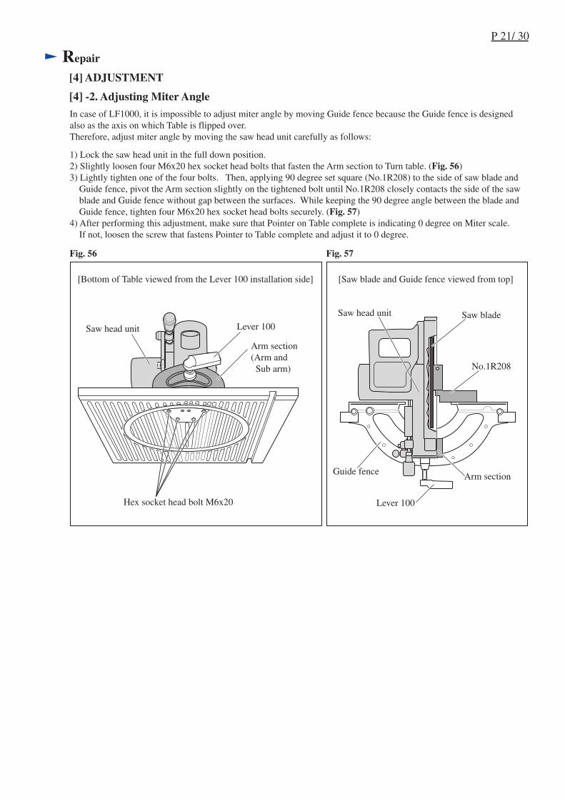
1) Lock the saw head unit in the full down position.2) Slightly loosen four M6x20 hex socket head bolts that fasten the Arm section to Turn table. (Fig. 56)3) Lightly tighten one of the four bolts. Then, applying 90 degree set square (No.1R208) to the side of saw blade and Guide fence, pivot the Arm section slightly on the tightened bolt until No.1R208 closely contacts the side of the saw blade and Guide fence without gap between the surfaces. While keeping the 90 degree angle between the blade and Guide fence, tighten four M6x20 hex socket head bolts securely. (Fig. 57)4) After performing this adjustment, make sure that Pointer on Table complete is indicating 0 degree on Miter scale. If not, loosen the screw that fastens Pointer to Table complete and adjust it to 0 degree.
[Bottom of Table viewed from the Lever 100 installation side] [Saw blade and Guide fence viewed from top]
In case of LF1000, it is impossible to adjust miter angle by moving Guide fence because the Guide fence is designedalso as the axis on which Table is flipped over.Therefore, adjust miter angle by moving the saw head unit carefully as follows:
Lever 100
Arm section(Arm and Sub arm)
Hex socket head bolt M6x20
Saw head unit
Saw head unit
Guide fence
No.1R208
Saw blade
Arm section
Lever 100
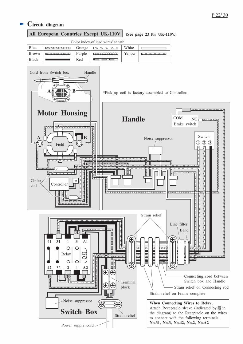
Circuit diagram
P 22/ 30
All European Countries Except UK-110V
Color index of lead wires' sheath
Black
White
Red
OrangeBlue
Brown Purple Yellow
A1313141
A2423242
Motor Housing
Switch Box
Handle
A B
A B
Cord from Switch box Handle
Noise suppressor
Terminalblock
Strain relief
Strain relief
Noise suppressor
Band
Line filter
Chokecoil
Connecting cord betweenSwitch box and Handle
When Connecting Wires to Relay;Attach Receptacle sleeve (indicated by inthe diagram) to the Receptacle on the wiresto connect with the following terminals:No.31, No.3, No.42, No.2, No.A2
Power supply cord
Strain relief on Frame complete
Strain relief on Connecting rod
*Pick up coil is factory-assembled to Controller.
Switch
Brake switch
Controller
Relay
Field
(See page 23 for UK-110V.)

Circuit diagram
P 23/ 30
UK-110V
Color index of lead wires' sheath
Black
White
Red
OrangeBlue
Brown Purple Yellow
*Pick up coil is factory-assembled to Controller.
When Connecting Wires to Relay;Attach Receptacle sleeve (indicated by inthe diagram) to the Receptacle on the wiresto connect with the following terminals:No.5, No.42, No.4 No.A2
A153141
A264242
Motor Housing
Switch Box
Handle
A B
A B
Cord from Switch box Handle
Strain relief
Strain relief
Band
Chokecoil
Connecting code betweenswitch box and handle
Noise suppressor
Noise suppressor Switch
Field
Relay
Strain relief on Frame complete
Strain relief on Connecting rod
Line filter
Terminalblock
Controller
Power supply cord
P 24/ 30
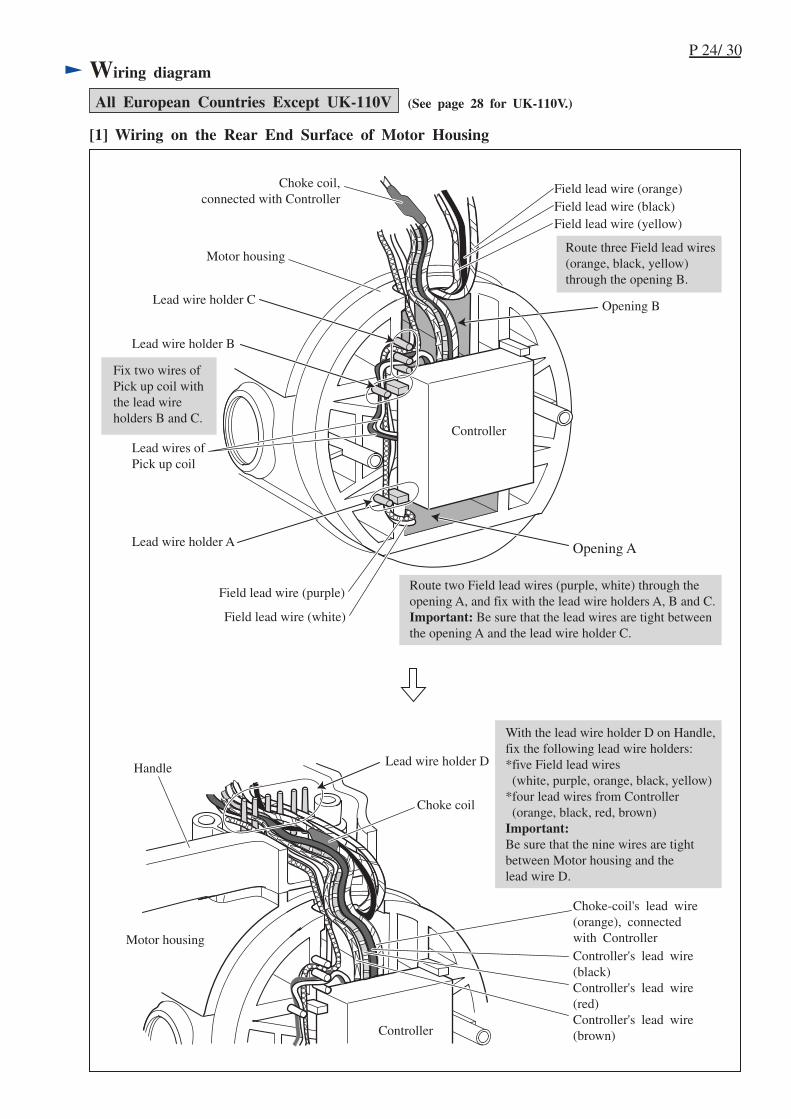
Wiring diagram
Lead wire holder D
Motor housing
Motor housing
Choke coil,connected with Controller
Choke coil
Controller
Controller
Opening B
Opening A
Field lead wire (orange)Field lead wire (black)Field lead wire (yellow)
Field lead wire (white)
Field lead wire (purple)
Lead wires ofPick up coil
Fix two wires ofPick up coil withthe lead wireholders B and C.
Handle
Lead wire holder B
Lead wire holder A
Route two Field lead wires (purple, white) through theopening A, and fix with the lead wire holders A, B and C.Important: Be sure that the lead wires are tight betweenthe opening A and the lead wire holder C.
Route three Field lead wires(orange, black, yellow)through the opening B.
[1] Wiring on the Rear End Surface of Motor Housing
Choke-coil's lead wire(orange), connectedwith ControllerController's lead wire(black)Controller's lead wire(red)Controller's lead wire(brown)
All European Countries Except UK-110V
With the lead wire holder D on Handle,fix the following lead wire holders:*five Field lead wires (white, purple, orange, black, yellow)*four lead wires from Controller (orange, black, red, brown)Important:Be sure that the nine wires are tightbetween Motor housing and thelead wire D.
Lead wire holder C
(See page 28 for UK-110V.)
P 25/ 30
Wiring diagram
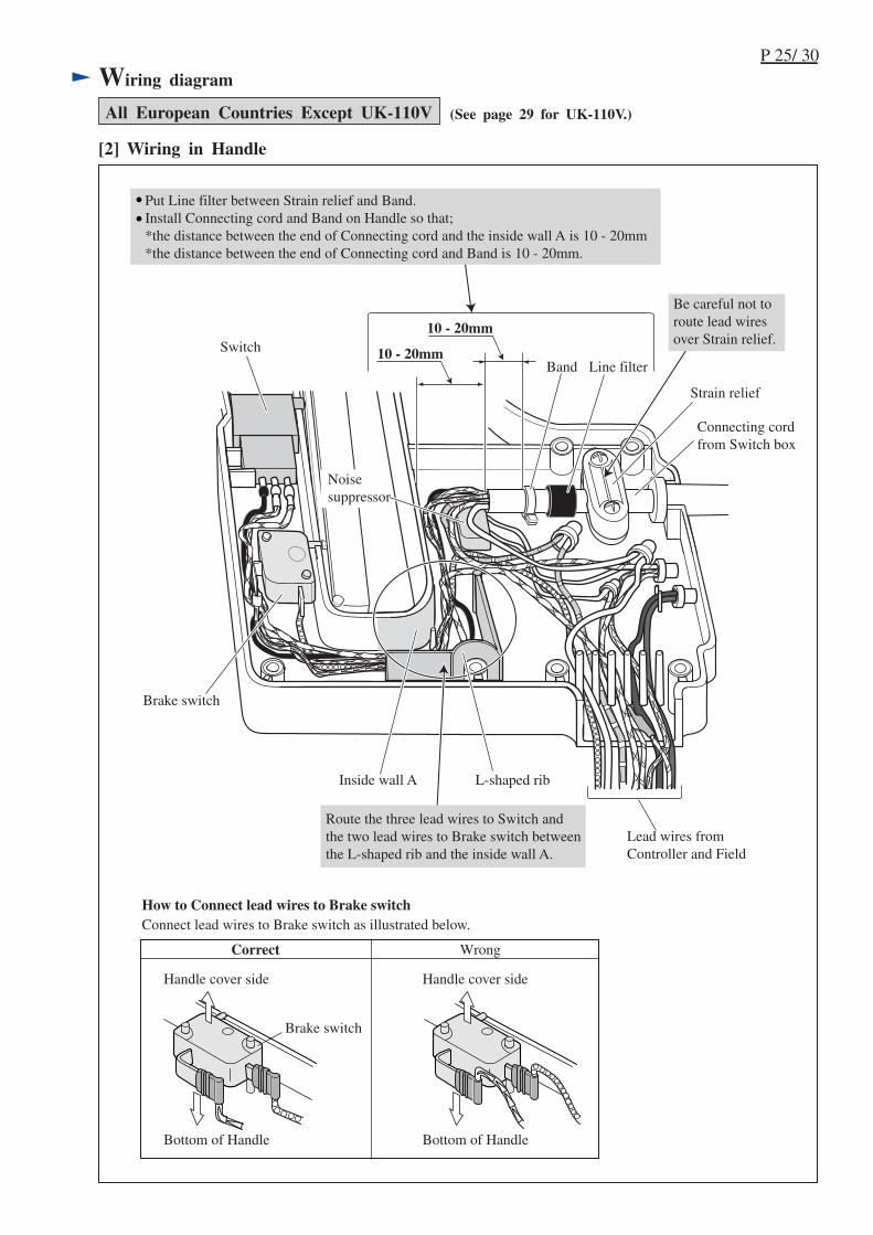
[2] Wiring in Handle
All European Countries Except UK-110V
SwitchLine filter
Strain relief
10 - 20mm
10 - 20mm
Connecting cordfrom Switch box
L-shaped ribInside wall A
Lead wires fromController and Field
Bottom of Handle
Handle cover side
Brake switch
Bottom of Handle
Handle cover side
Connect lead wires to Brake switch as illustrated below.How to Connect lead wires to Brake switch
Correct Wrong
Brake switch
Band
Noise suppressor
Be careful not to route lead wires over Strain relief.
Put Line filter between Strain relief and Band.Install Connecting cord and Band on Handle so that;*the distance between the end of Connecting cord and the inside wall A is 10 - 20mm*the distance between the end of Connecting cord and Band is 10 - 20mm.
Route the three lead wires to Switch andthe two lead wires to Brake switch betweenthe L-shaped rib and the inside wall A.
(See page 29 for UK-110V.)
P 26/ 30
Wiring diagram
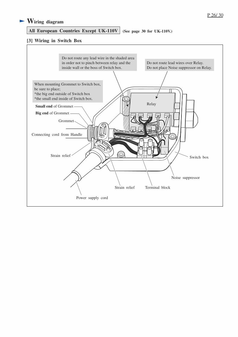
[3] Wiring in Switch Box
All European Countries Except UK-110V
Switch box
Grommet
Connecting cord from Handle
Power supply cord
Relay
When mounting Grommet to Switch box,be sure to place;*the big end outside of Switch box*the small end inside of Switch box.
Small end of Grommet
Big end of Grommet
Strain relief
Strain relief Terminal block
Noise suppressor
Do not route lead wires over Relay.Do not place Noise suppressor on Relay.
Do not route any lead wire in the shaded areain order not to pinch between relay and theinside wall or the boss of Switch box.
(See page 30 for UK-110V.)
P 27/ 30
Wiring diagram
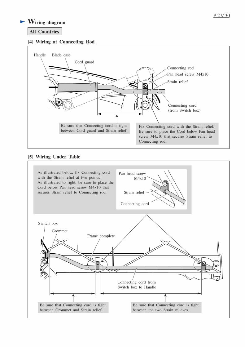
[4] Wiring at Connecting Rod
All Countries
[5] Wiring Under Table
Switch box
Grommet
Strain relief
Pan head screwM4x10
Frame complete
Connecting cord fromSwitch box to Handle
Connecting cord
Pan head screw M4x10
Connecting rod
Strain relief
Handle
Connecting cord(from Switch box)
Cord guard
Blade case
Be sure that Connecting cord is tightbetween Cord guard and Strain relief.
Fix Connecting cord with the Strain relief.Be sure to place the Cord below Pan headscrew M4x10 that secures Strain relief toConnecting rod.
Be sure that Connecting cord is tightbetween Grommet and Strain relief.
Be sure that Connecting cord is tightbetween the two Strain relieves.
As illustrated below, fix Connecting cordwith the Strain relief at two points.As illustrated to right, be sure to place theCord below Pan head screw M4x10 thatsecures Strain relief to Connecting rod.
P 28/ 30
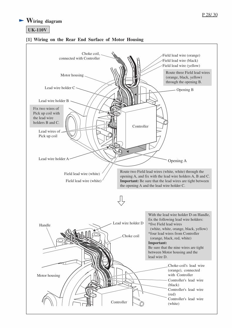
Wiring diagram
Lead wire holder D
Motor housing
Motor housing
Choke coil,connected with Controller
Choke coil
Controller
Controller
Opening B
Opening A
Field lead wire (orange)Field lead wire (black)Field lead wire (yellow)
Field lead wire (white)
Field lead wire (white)
Lead wires ofPick up coil
Fix two wires ofPick up coil withthe lead wireholders B and C.
Handle
Lead wire holder B
Lead wire holder A
Route two Field lead wires (white, white) through theopening A, and fix with the lead wire holders A, B and C.Important: Be sure that the lead wires are tight betweenthe opening A and the lead wire holder C.
Route three Field lead wires(orange, black, yellow)through the opening B.
[1] Wiring on the Rear End Surface of Motor Housing
Choke-coil's lead wire(orange), connectedwith ControllerController's lead wire(black)Controller's lead wire(red)Controller's lead wire(white)
UK-110V
With the lead wire holder D on Handle,fix the following lead wire holders:*five Field lead wires (white, white, orange, black, yellow)*four lead wires from Controller (orange, black, red, white)Important:Be sure that the nine wires are tightbetween Motor housing and thelead wire D.
Lead wire holder C

P 29/ 30
Wiring diagram
[2] Wiring in Handle
UK-110V
SwitchLine filter
Strain relief
10 - 20mm
10 - 20mm
Connecting cordfrom Switch box
L-shaped ribInside wall A
Lead wires fromController and Field
Band
Noise suppressor
Be careful not to route lead wires over Strain relief.
Put Line filter between Strain relief and Band.Install Connecting cord and Band on Handle so that;*the distance between the end of Connecting cord and the inside wall A is 10 - 20mm*the distance between the end of Connecting cord and Band is 10 - 20mm.
Route the three lead wires to Switch betweenthe L-shaped rib and the inside wall A.
P 30/ 30
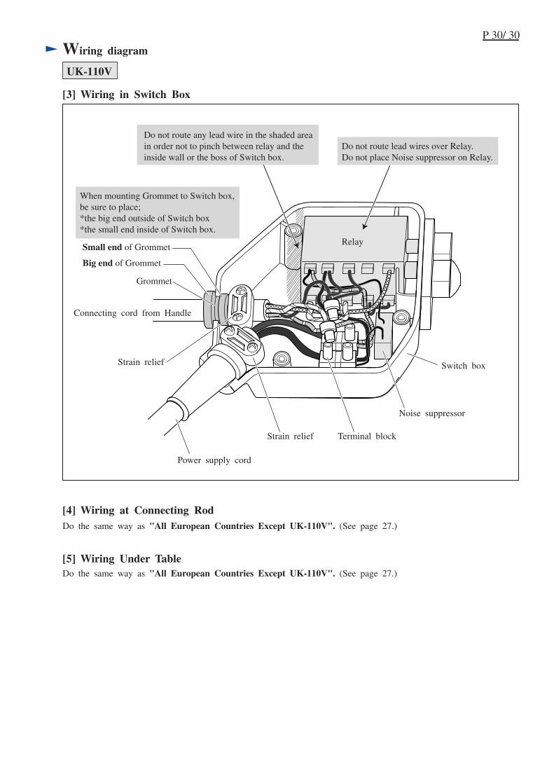
Wiring diagram
[3] Wiring in Switch Box
UK-110V
Switch box
Grommet
Connecting cord from Handle
Power supply cord
Relay
When mounting Grommet to Switch box,be sure to place;*the big end outside of Switch box*the small end inside of Switch box.
Small end of Grommet
Big end of Grommet
Strain relief
Strain relief Terminal block
Noise suppressor
Do not route lead wires over Relay.Do not place Noise suppressor on Relay.
Do not route any lead wire in the shaded areain order not to pinch between relay and theinside wall or the boss of Switch box.
[4] Wiring at Connecting RodDo the same way as "All European Countries Except UK-110V". (See page 27.)
Do the same way as "All European Countries Except UK-110V". (See page 27.)
[5] Wiring Under Table