
Technical Information Vol.04
17
Leader Electronics Corporation Technical Information Series Vol.04 IP Conversion of Broadcasting 1 … Overview 01 Background 02 The Technologies Supporting IP Transmission 03 Basic Knowledge about Communication The content of this document is as of July 2020. The company and product names in this document are trademarks or registered trademarks of their respective holders.
-
Upload
khangminh22 -
Category
Documents
-
view
0 -
download
0
Transcript of Technical Information Vol.04

Leader Electronics Corporation Technical Information Series Vol.04
IP Conversion of Broadcasting 1 … Overview
01 Background 02 The Technologies Supporting IP Transmission 03 Basic Knowledge about Communication The content of this document is as of July 2020.
The company and product names in this document are trademarks or
registered trademarks of their respective holders.

IP Conversion of Broadcasting 1
01
01 Background Overview about IP transmission
Overview
Until now, in broadcast stations, from video production to transmissions, SDI (Serial Digital Interface) has been operated mainly, which is an industry specific standard. But in recent years, resolution (2K→4K/8K), bit depth (8bit→10bit/12bit), and frame rate (60p→120p) have been improved. In other words, as the image quality has been improved, it need to process more and more amount of data. As a result, some problems have become apparent such as the number of BNC cables and transmission distance.
Therefore, IP (Internet Protocol) technology are attracted attention. The cables for IP are light comparing to BNC cable so we can extend the transmission distance, and possibly reduce the cost in the future because the IP technology is making progress dramatically. In addition, with PTP, the Black Burst signals (BB) is no longer necessary and we can construct more flexible systems, so it has become widely used in broadcasting industry.
Comparing SDI with IP
Transmission Speed
In 1990, SD-SDI (270Mbsp) was defined. At that time, the Ethernet transmission speed was about 10Mbps which is significantly insufficient for broadcasting. Therefore, in Broadcast stations, SDI, which is the only standards using coaxial cables, has been applied for a long times. However the transmission by coaxial cables is coming up to the limit because the videos have gradually evolved to 1080i (1.5Gbps), 1080p (3Gbps), 4K/30p (6Gbps), 4K/60p (12Gbps). And we should predict that 8K is become prevalent in the future. On the other hand, the Ethernet has grown rapidly in contrast to SDI, with 1 Gbps in 2000, 100 Gbps in 2010, and 400 Gbps as of 2019, and more in the future.
Cost
SDI requires dedicated instruments due to industrial unique standards. And equipment are required update every time developed new formats. However the costs tend to be expensive due to its small market. On the other hand, IP is expected to dramatic cost down because we can use highly versatile instruments such as switching hubs.
Multiplex
In SDI, one signal is transmitted by one cable. Against that, in IP, multiple signals can be transmitted by one cable. For example, when we use 100 Gbps network, more than 60 HD-SDI (1.5 Gbps) signals can be transmitted by one cable. It can also be supported format expansion such as 4K and 8K. In addition to video signals, control signals, synchronization signals,

IP Conversion of Broadcasting 1
02
intercoms, and all shooting data can be transmitted via IP, making it possible to reduce the number of cables and equipment.
Bidirectional
Bidirectional communication is available in IP unlike unidirectional communication in SDI with fixed inputs and outputs. Therefore, we are only required to connect each equipment to switching hub, it makes possible to construct high flexible systems.
Connection Image
For SDI, each equipment is connected in processing in order. To synchronize each equipment, they require the external sync signal. Since SDI is unidirectional communication, basically we only connect each equipment to output images without any special settings.
Figure | Connection image for SDI
On the other hand, IP is simply constructed with only connecting switching hub to each equipment. Furthermore, using PTP, which is synchronized protocol for IP, it is also not required the external sync signal. Since IP is bidirectional communication, we have to construct the setting for each equipment to output images.
Figure | Connection image for IP

IP Conversion of Broadcasting 1
03
02 The Technologies Supporting IP transmission The technologies and the standards for IP transmission
Connections
In SDI, we use BNC connector and BNC cables for video signals transmissions. In IP, we mainly use the port and fiber-optic cables called SFP. In this section, we will explain the connections using fiber-optic cable.
SFP
SFP is an abbreviation for Small Form-factor Pluggable. We usually connect the SFP port to the fiber-optic cable through the SFP transceiver. The SFP transceivers can convert the electrical signals from the equipment side and the optical signals from the cable side mutually.
Figure | SFP connection
SFP transceivers has several types several types as below classified by the network transmission speed. Here, available SFP transceiver type could be different by the equipment even if its appearance are similar, so we have to take care for that when selecting them. In addition, transmission speed of the SFP receiving ports are required to be same as that of SFP transmission port.
SFP port SFP transceiver Transmission speed
SFP SFP 1Gbps
SFP+ 10Gbps
SFP28 25Gbps
QSFP QSFP+ 40Gbps
QSFP28 100Gbps

IP Conversion of Broadcasting 1
04
Fiber-optic
In optical communication, the cable which transmits the signals is called fiber-optic. A fiber-optic consists of two parts. One is "core" through which signals transmit, the other is "clad" which confines signals inside the core. Optical signals are transmitted by total reflection at the interface between core and clads. Fiber-optic cables can transmit a large amount of data at high speed over long distances. However we need to take care to handle fiber-optic cables because the core and clad are usually made of glass.
Fiber-optic cables are roughly categorized MMF(Multi Mode Fiber) and SMF(Single Mode Fiber). Here, "Mode" refers to the way that optical signals are transmitted.
MMFs have a large core diameter of 50 μm or 62.5 μm and can transmit optical signals in multiple modes. But they could also degrade the signal and lose data. They are cheaper than SMF, but are not suitable for long-distance communication. For example, in the case of 10GBASE-SR standard (10Gbps, MMF), the transmission distance is up to 300m.
Figure | MMF
SMF has a small core diameter of 9.2 μm, and signal attenuation and deterioration are suppressed by transmitting optical signals in only one mode. It is more expensive than MMF, but it is suitable for long-distance communication. For example, in the case of 10GBASE-LR standard (10Gbps, SMF), the transmission distance is up to 10km.
Figure | SMF

IP Conversion of Broadcasting 1
05
Packetization for SDI Signals
In this section, we will explain the standards when packetize uncompressed SDI signals. See more details, separate volume “Content edition”.
Overview
In 2012, SMPTE ST 2022-6 was stipulated as the standard of packetization for uncompressed SDI signals. SMPTE ST 2022-6 is the system that is packetized the entire SDI signal. And it supports up to 3G-SDI.
Figure | Image of SMPTE ST 2022-6
In this standard, the data of video, audio, and auxiliary are mixed in one packet. So it was not efficient for receiving individual factor signal. Therefore, from 2017 to 2018, SMPTE ST 2110-20, which packetizes video data, SMPTE ST 2110-30, which is packetizes audio data, and SMPTE ST 2110-40, which is the standard packetized auxiliary data, were stipulated.
Figure | Image of SMPTE ST 2110
Moreover, SMPTE ST 2110 can synchronize with high accuracy by using PTP, which is the synchronization protocol stipulated in SMPTE ST 2059.

IP Conversion of Broadcasting 1
06
Standards SMPTE ST 2022
SMPTE ST 2022 consists of seven standards from 2022-1 to 2022-7.In this section, we will explain from 2022-5 to 2022-7. These are related to uncompressed SDI signals.
Standard Name Overview
SMPTE ST 2022-5 Forward Error Correction for
Transport of High Bit Rate Media
Signals over IP Networks (HBRMT)
forward error correction for 2022-6
SMPTE ST 2022-6 Transport of High Bit Rate Media
Signals over IP Networks (HBRMT)
Packetization forthe entire SDI signal
SMPTE ST 2022-7 Seamless Protection Switching of
SMPTE ST 2022 IP Datagrams
Seamless signal switching for redundant
transmission lines
SMPTE ST 2110
SMPTE ST 2110 consists of six standards from 2022-10 to 2022-40.And these generic name is "Professional Media Over Managed IP Networks". SMPTE ST 2110 is not included the specification for error correction and signal switching. But we can use SMPTE ST 2022-7.
Standard Name Overview
SMPTE ST 2110-10 System Timing and Definitions Timings and rules for the entire systems
SMPTE ST 2110-20 Uncompressed Active Video Packetization for the video data
SMPTE ST 2110-21 Traffic Shaping and Delivery Timing
for Video
Transmission timings for video data
SMPTE ST 2110-30 PCM Digital Audio Packetization for AES67 format audio
data
SMPTE ST 2110-31 AES3 Transparent Transport Packetization for AES3 format audio data
SMPTE ST 2110-40 SMPTE ST 291-1 Ancillary Data Packetization for auxiliary data

IP Conversion of Broadcasting 1
07
PTP
In this section, we will explain PTP (Precision Time Protocol), which is the protocol for synchronizing on IP networks. See more details, separate volume “synchronization edition (under editing)”.
Overview
PTP is the protocol that substitutes for external sync signal (Black Burst). PTP synchronizes of video or audio by accurately adjusting the time of the equipment on the network. PTP used in various situations, not only the broadcasting industry but also the telecom and the financial industry.
NTP (Network Time Protocol) is the time synchronization protocol, too. Until now, NTP had been used widely. However, the accuracy of NTP is 1 millisecond, while the accuracy of PTP is about 1 microsecond. So PTP makes it possible to synchronize more accurate than NTP. For your information, the broadcasts require the synchronization accuracy 200 nanoseconds to 300 nanoseconds.
Standards IEEE 1588
This is a fundamental standards for PTP, and there are two. “v1” was specified in 2002, and “v2” as specified in 2008. But v1 and v2 are not compatible.
Standard name Name Overview
IEEE 1588-2002
(v1)
IEEE Standard for a Precision Clock
Synchronization Protocol for
Networked Measurement and
Control Systems
Adopted by Dante (network audio
standard)
IEEE 1588-2008
(v2)
IEEE Standard for a Precision Clock
Synchronization Protocol for
Networked Measurement and
Control Systems
Adopted by SMPTE ST 2022-6,SMPTE ST
2110, and AES67

IP Conversion of Broadcasting 1
08
SMPTE ST 2059
This is a PTP standard adapted for broadcast equipment.
Standard name Name Overview
SMPTE ST 2059-1 Generation and Alignment of
Interface Signals to the SMPTE Epoch
How to calculate for video and audio
phase starting from the SMPTE epoch.
SMPTE ST 2059-2 SMPTE Profile for Use of IEEE-1588
Precision Time Protocol in
Professional Broadcast Applications
SMPTE profile when used IEEE 1588 in
broadcast.
SMPTE EG 2059-10 Introduction to the New
Synchronization System
Introduction and usage examples for PTP
Control
In this section, we will explain the standards for controlling networks. See more details, separate volume “Control edition (under editing)”.
Overview
Above as packetization for SDI signals and the PTP are conversions of conventional SDI signals to IP On the other hand, the control is a peculiar element of the IP conversion. In this section, we will explain that IS-04 and IS-05 in NMOS(Networked Media Open Specifications), which is established by AMWA(Advanced Media Workflow Association). AMWA refers the international organization which standardize control systems. NMOS refers the standard control standards.
Standard IS-04 (Discovery and Registration)
This standard is for discovery and registration of the equipment on networks. The following API (Application Programming Interface) is provided.
・NodeAPI ・QueryAPI ・RegistrationAPI
IS-05 (Device Connection Management)
This standard is for management for connection between devices. The following API (Application Programming Interface) is provided.
・ConnectionAPI

IP Conversion of Broadcasting 1
09
03 Basic Knowledge about Communication About basic knowledge of communication required for IP transmission
IP
IP is an abbreviation for Internet Protocol, which is a mechanism for subdividing the data you want to send into a constant size packets and transmitting them over a network. Subdividing into packets makes it avoid to occupy the network for long times and minimize retransmission due to error occasion. On the receiving side, you can obtain original data by restoring the packet data.
On the other hand, IP is said low reliable protocol. Because IP packets are not arrived in receiver side in the right order or are lost the data during transmitting. To prevent them, TCP/IP formats, which are combined IP with TCP (Transmission Control Protocol), are used widely. (However, in broadcast field, UDP is used instead of TCP.)
Protocol
Protocol means "Rule". And The "P" in "IP" is an abbreviation for protocol. Therefore the case of "IP", it indicates "the rules when using internets". Protocol has various types besides IP. And they are defined by organizations such as IETF (Internet Engineering Task Force).
Figure | One example of the protocol

IP Conversion of Broadcasting 1
10
Packet
In communicating mainly by IP, packets refer to the data subdivided into a certain size. The packet consists of IP header and data. The IP header has various information related to the data.
For example, in the case of an IP packets, they indicate the data with an IP header attached. The IP header has various information the IP address, etc.
Figure | Packet
In the case of a TCP, the segment indicates the data with a TCP header attached. But, they are also called packet. So in this document, we will call them packet.
Figure | Segment
In the case of a UDP, the datagram indicates the data with a UDP header attached. But, they are also called packet. So in this document, we will call them packet.
Figure | Datagram
As a supplementary explanation, in the case of an Ethernet, the frame indicates the data with an Ethernet header and the FCS (Frame Check Sequence) attached. This FCS indicates the attached data to detect errors.
Figure | Flame

IP Conversion of Broadcasting 1
11
Encapsulation
One packet consists of the header and the data. We reckon them as one data, and attach another header. This is called encapsulation. For example, the TCP packets consist of the TCP header and the data. And we reckon them as one data, and attach the IP header. Furthermore, removing the header from the packet and retrieving the data is called decapsulation.
Figure | Encapsulation

IP Conversion of Broadcasting 1
12
OSI Reference Model / TCP / IP Model
The following is a standardized communication mechanism for connecting various network devices to each other. OSI reference model are classified the functions required for communication into seven layers. They are almost not used actually, despite important concept to know the communication mechanism. On the other hand, TCP/IP model consisted of four layers are used widely. They has different contents. But both models have the layerized function, each layer is independent. The transmitting side sends data from the upper layer to the lower layer, and the receiving side passes the data received in the lower layer to upper layer. With this, communications are established.
Figure | OSI reference model / TCP / IP model
※ There are various theories about supporting OSI reference model ,TCP/IP model supports, and the
protocol accompanying each layers. In this section, we described one example.
In the below, we will explain the flow of data sending and receiving by using OSI reference model. As an example, taking RTP (Real-time Transport Protocol), which is the protocol used for broadcast. And we will use UDP, IP, and Ethernet as communications protocol.
IP Conversion of Broadcasting 1
13
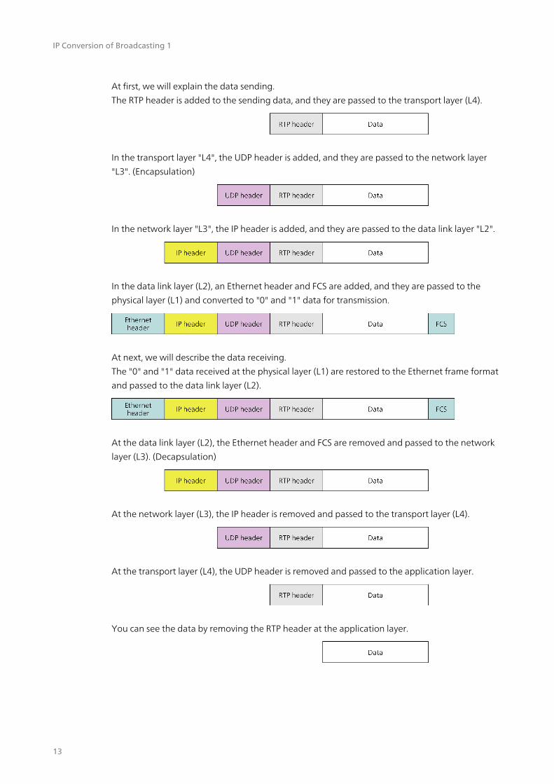
At first, we will explain the data sending. The RTP header is added to the sending data, and they are passed to the transport layer (L4).
In the transport layer "L4", the UDP header is added, and they are passed to the network layer "L3". (Encapsulation)
In the network layer "L3", the IP header is added, and they are passed to the data link layer "L2".
In the data link layer (L2), an Ethernet header and FCS are added, and they are passed to the physical layer (L1) and converted to "0" and "1" data for transmission.
At next, we will describe the data receiving. The "0" and "1" data received at the physical layer (L1) are restored to the Ethernet frame format and passed to the data link layer (L2).
At the data link layer (L2), the Ethernet header and FCS are removed and passed to the network layer (L3). (Decapsulation)
At the network layer (L3), the IP header is removed and passed to the transport layer (L4).
At the transport layer (L4), the UDP header is removed and passed to the application layer.
You can see the data by removing the RTP header at the application layer.

IP Conversion of Broadcasting 1
14
IP Address
IP Address is the abbreviation of Internet Protocol Address. This is a unique identification number assigned each instrument connected to the internet or the LAN. IP Address consists 32 bits, and they are shown as the formats from "0.0.0.0" to "255.255.255.255".These are called IPv4, and the total numbers of them are about 4.3 billion. But the depletion of IP addresses has already become a problem. So the transition to IPv6 is progressing.
IPv6 consists 128 bits, they are shown from "0:0:0:0:0:0:0:0" to "FFFF: FFFF: FFFF: FFFF: FFFF: FFFF: FFFF: FFFF". IPv4 and IPv6 are not compatible. So we are required So we are required IPv6 supports for network equipment.
MAC Address
MAC address is an abbreviation for Media Access Control Address. They are unique identification number and is assigned each equipment connected to the network. In principle, once assigned, these are not changed. They consists of a total of 48 bits and are shown from "00:00:00:00:00:00" to "FF: FF: FF: FF: FF: FF". The first 24 bits are called OUI (Organizationally Unique Identifier), which is a unique number representing the manufacturer name. The latter 24 bits are the numbers assigned by the manufacturer for each product. The total number of MAC addresses are about 70 trillion, and it is said that there is no concern about depletion at this time.

IP Conversion of Broadcasting 1
15
L2 Switch (Switching Hub, Ethernet Switch)
”L2“ in L2 Switch refers second layer of OSI reference model, which is the data link layer. L2 Switch is an equipment which operates on this data link layer. This judges destinations according to MAC address and send the data to equipment only required.
Figure | L2 Switch
Moreover L3 Switch is an equipment which operates on network layer, which is third layer of OSI reference model. This judges destinations according to IP address and send the data.
Furthermore the equipment which operates the physical layer, which is first layer of OSI reference model, are refered the repeater Hub. It sends the received data to all equipment. If received data is not for myself, the data are discarded. Currently, repeater hubs are not used so well.
Figure | Repeater Hub

IP Conversion of Broadcasting 1
16
About structure of the documents
"Vol.4 IP Conversion of Broadcasting" has four parts in total. This documents is “Overview edition”. Please take a look at the followings as well.
・IP Conversion of Broadcasting 1 Overview Background, Technologies that support
IP transmission, Basic knowledge about communication * This document ・IP Conversion of Broadcasting 2 Contents About SMPTE ST 2110 * Under editing ・IP Conversion of Broadcasting 3 Synchronization About PTP * Under editing ・IP Conversion of Broadcasting 4 Control About NMOS * Under editing
Address
Phone
URL
Published
2-6-33 Tsunashima-Higashi, Kohoku-ku, Yokohama-shi, Kanagawa Prefecture 223-8505, Japan
+81-45-541-2123
www.leader.co.jp/en
April 8, 2021 Ver. 1