Standard specifications SC400L-04/05-FD11 SC500-04/05 ...
26
Standard specifications SC400L-04/05-FD11 SC500-04/05-FD11 1st edition 1306, SSCEN-053-001, 001
-
Upload
khangminh22 -
Category
Documents
-
view
2 -
download
0
Transcript of Standard specifications SC400L-04/05-FD11 SC500-04/05 ...
Standard specifications
SC400L-04/05-FD11
SC500-04/05-FD11
1st edition
1306, SSCEN-053-001, 001
Contents
Page
1. Outline..............................................................................................................................1
2. Basic specifications..........................................................................................................2
3. Robot dimensions and working envelope ........................................................................3
4. Detail of load mounting face ............................................................................................5
5. Installation ........................................................................................................................8
8. Allowable load ................................................................................................................ 11
7. Option specifications......................................................................................................14
8. Application wiring and piping..........................................................................................15
9. Transporting ...................................................................................................................20
10. Delivery style (specification which contains a robot) ...................................................22
11. Consuming power (Robot + Controller) .......................................................................22
12. Paint color ....................................................................................................................22
13. Warranty.......................................................................................................................22

Page-1
1. Outline
NACHI ROBOT has used mechatronic techniques, cultivated throughout the last few decades, to
supply robots suited for industries utilizing welding and material handling techniques.
SC500 (pay load : 500kg) and SC400L (pay load : 400kg) is the robot, which is optimal for
application of material handling of the big and heavy load weight.
< Characteristic >
1. It is possible to apply to car body and heavy load weight, which is not possible to apply formerly. 2. It is possible to apply to big work by wide operation range. Maximum reach of SC500 is 2703
mm and SC400L is 3623 mm.
3. It is possible to apply to every material handling application by big wrist torque “1960 N・m”
Page-2
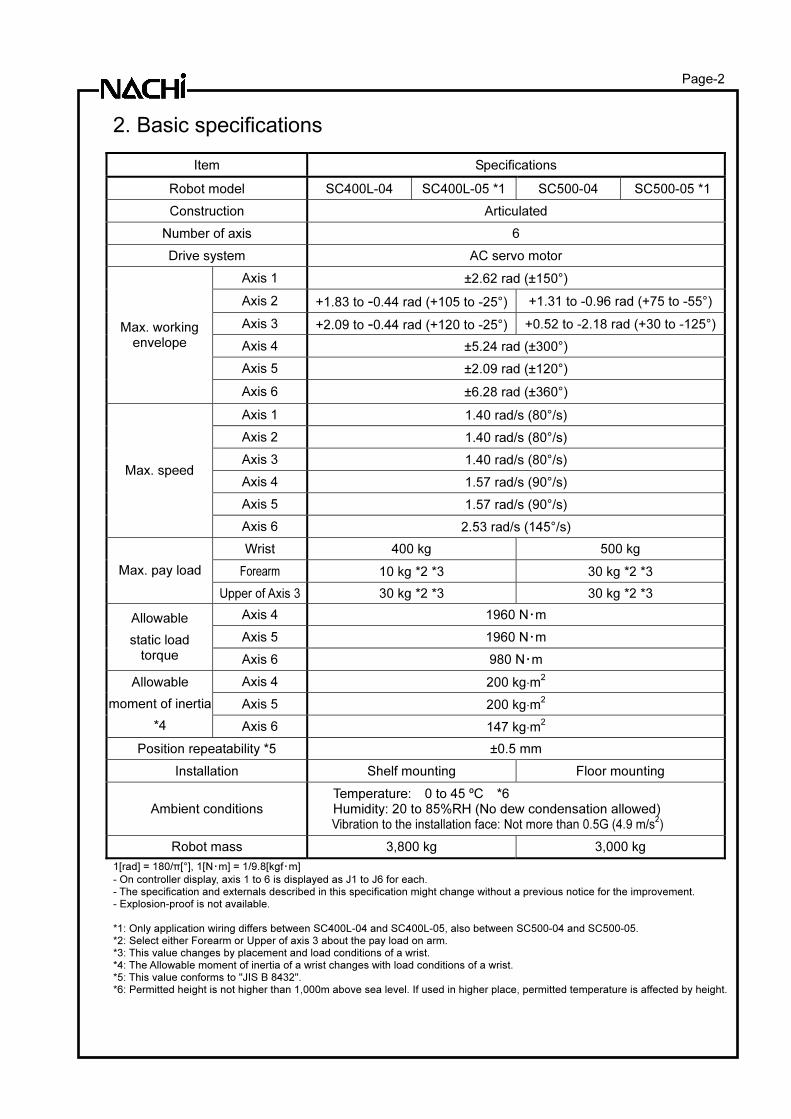
2. Basic specifications
Item Specifications
Robot model SC400L-04 SC400L-05 *1 SC500-04 SC500-05 *1
Construction Articulated
Number of axis 6
Drive system AC servo motor
Axis 1 ±2.62 rad (±150°)
Axis 2 +1.83 to -0.44 rad (+105 to -25°) +1.31 to -0.96 rad (+75 to -55°)
Axis 3 +2.09 to -0.44 rad (+120 to -25°) +0.52 to -2.18 rad (+30 to -125°)
Axis 4 ±5.24 rad (±300°)
Axis 5 ±2.09 rad (±120°)
Max. working envelope
Axis 6 ±6.28 rad (±360°)
Axis 1 1.40 rad/s (80°/s)
Axis 2 1.40 rad/s (80°/s)
Axis 3 1.40 rad/s (80°/s)
Axis 4 1.57 rad/s (90°/s)
Axis 5 1.57 rad/s (90°/s)
Max. speed
Axis 6 2.53 rad/s (145°/s)
Wrist 400 kg 500 kg
Forearm 10 kg *2 *3 30 kg *2 *3 Max. pay load
Upper of Axis 3 30 kg *2 *3 30 kg *2 *3
Axis 4 1960 N・m
Axis 5 1960 N・m
Allowable
static load torque Axis 6 980 N・m
Axis 4 200 kg⋅m2
Axis 5 200 kg⋅m2
Allowable
moment of inertia
*4 Axis 6 147 kg⋅m2
Position repeatability *5 ±0.5 mm
Installation Shelf mounting Floor mounting
Ambient conditions Temperature: 0 to 45 ºC *6 Humidity: 20 to 85%RH (No dew condensation allowed) Vibration to the installation face: Not more than 0.5G (4.9 m/s
2)
Robot mass 3,800 kg 3,000 kg
1[rad] = 180/π[°], 1[N・m] = 1/9.8[kgf・m]
- On controller display, axis 1 to 6 is displayed as J1 to J6 for each.
- The specification and externals described in this specification might change without a previous notice for the improvement. - Explosion-proof is not available.
*1: Only application wiring differs between SC400L-04 and SC400L-05, also between SC500-04 and SC500-05. *2: Select either Forearm or Upper of axis 3 about the pay load on arm. *3: This value changes by placement and load conditions of a wrist.
*4: The Allowable moment of inertia of a wrist changes with load conditions of a wrist. *5: This value conforms to "JIS B 8432". *6: Permitted height is not higher than 1,000m above sea level. If used in higher place, permitted temperature is affected by height.
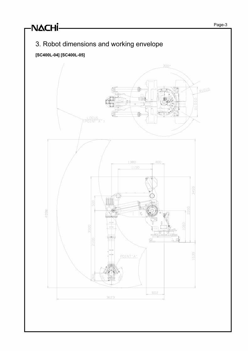
Page-3
3. Robot dimensions and working envelope [SC400L-04] [SC400L-05]
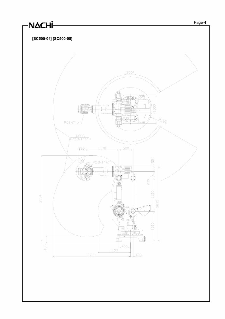
Page-4
[SC500-04] [SC500-05]
Page-5
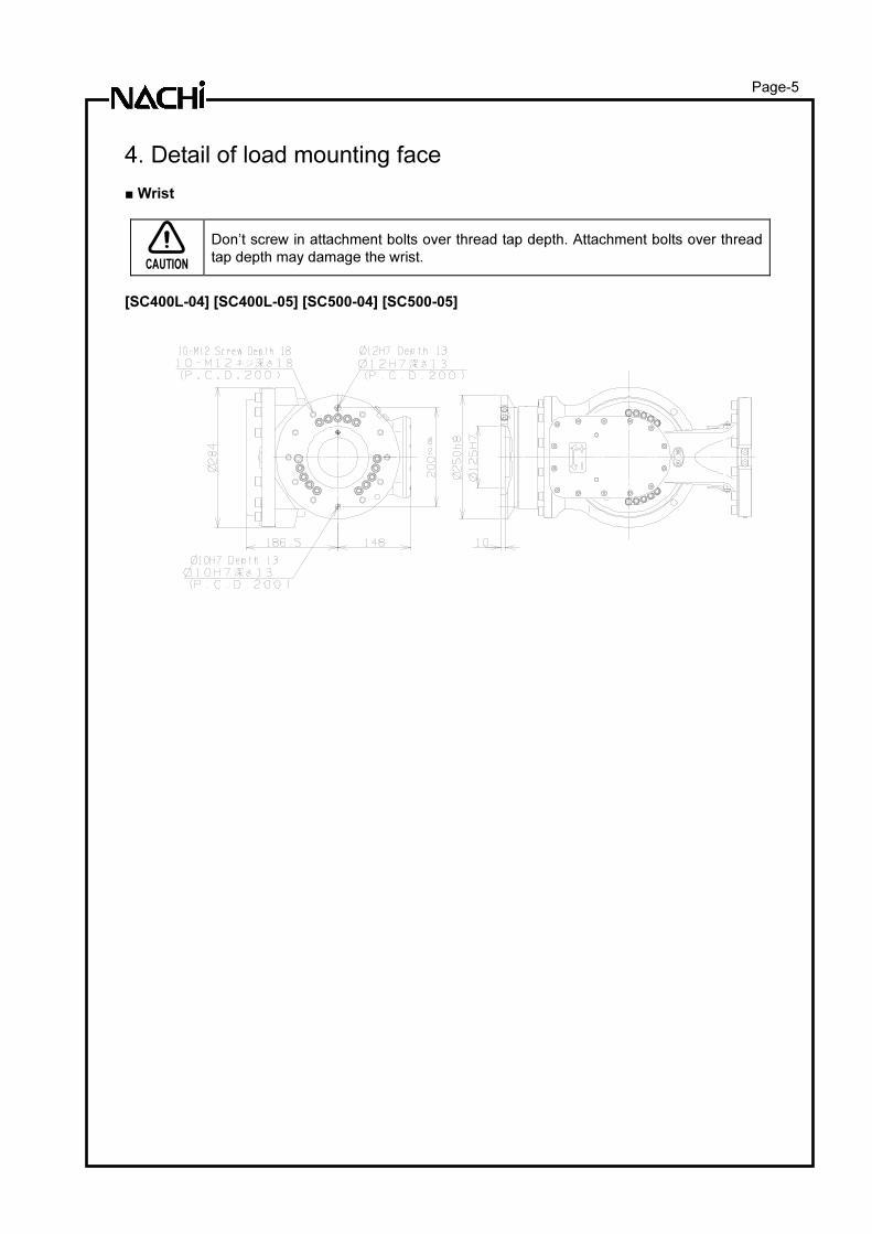
4. Detail of load mounting face ■ Wrist
CAUTION
Don’t screw in attachment bolts over thread tap depth. Attachment bolts over thread
tap depth may damage the wrist.
[SC400L-04] [SC400L-05] [SC500-04] [SC500-05]
Page-6
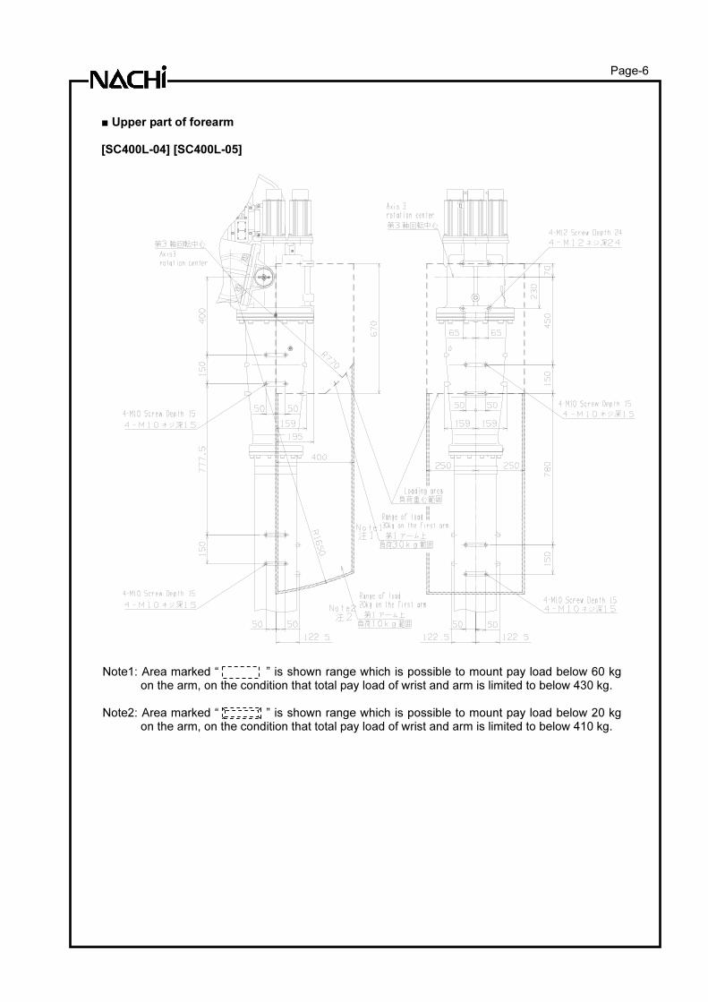
■ Upper part of forearm [SC400L-04] [SC400L-05]
Note1: Area marked “ ” is shown range which is possible to mount pay load below 60 kg
on the arm, on the condition that total pay load of wrist and arm is limited to below 430 kg. Note2: Area marked “ ” is shown range which is possible to mount pay load below 20 kg
on the arm, on the condition that total pay load of wrist and arm is limited to below 410 kg.
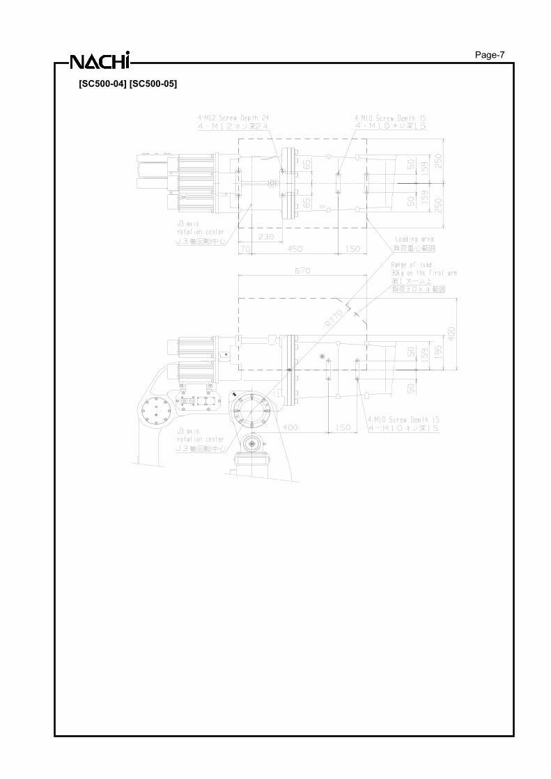
Page-7
[SC500-04] [SC500-05]
Page-8
5. Installation
The installation location and the installation procedure of the robot are critical factors to maintain
robot functions. The ambient conditions of installation location not only have influence on the life of
mechanical sections of the robot, but also get involved in safety issues. Consequently, strictly observe
the environmental conditions shown below. Furthermore, utmost care should be exerted for the
installation procedure and the foundation for the robot in order to maintain the robot performance.
Strictly observe the installation procedure for the robot provided below.
Installation To install the robot, give it first priority to thoroughly consider safety of workers and take safety
measures. The following section describes precautions for this purpose.
Safety measures against entry in the robot operating area
WARNING
While the robot is in operation, workers are in danger of coming in contact with the robot. To avoid that, install a guard fence so as to keep the worker away from the robot. Not doing so will cause the workers or other persons to accidentally enter the operating area, thus resulting in accidents.
■ Installation location and ambient conditions
Conditions (temperature, humidity, height and vibration) are written in “2 Basic Specifications”.
Further ambient conditions listed below must be observed.
(1) Location with the drainage structure so that swivel base is not flooded, when the liquid such as
water or cutting fluid is splashed on the robot body
(2) Location with no flammable or corrosive fluid or gas.
(3) Type D grounding (the grounding resistance is 100Ω or less) is necessary.
■ Installation procedure
While robot moves, large reaction force is applied to the swiveling base from all directions. Consequently, the robot should be installed in such a manner that the foundation endures reaction force caused by accelerating or decelerating the speed to lock the robot, not to mention that it endures static loads. To install the robot on the floor, if the floor concrete is not less than 150 mm in thickness, repair uneven spots, cracks, and others on the floor, and then install the robot with the use of 12 bolts (option) of M24 (JIS: Strength class 12.9) not less than 75mm and plain washers (option) of not less than 4.5 mm in thickness and HRC35 in hardness. At this time, apply a coating of lubricating
oil to the threaded parts of the bolts, and then torque the bolts to 560 ± 30 N�m. Furthermore, to install the robot in an exact position, use location pins (option). If the floor concrete is not more than 150 mm in thickness, an independent foundation should be constructed. Inspect the foundation prior to the robot installation, and then construct the foundation, if necessary.
Allowable load of foundation bolt
Robot Model Allowable repeated tensile load per bolt when the robot is installed with 12 bolts
SC400L-04 SC400L-05 SC500-04 SC500-05
Approximately 12,000N
Page-9
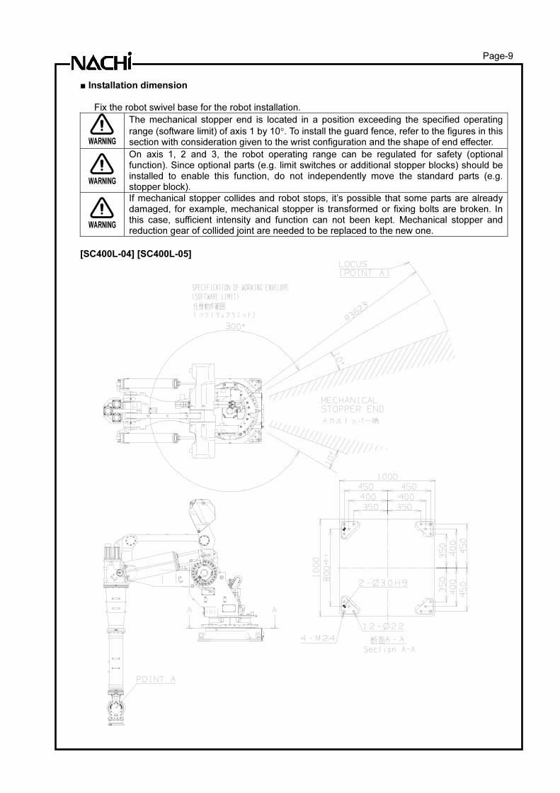
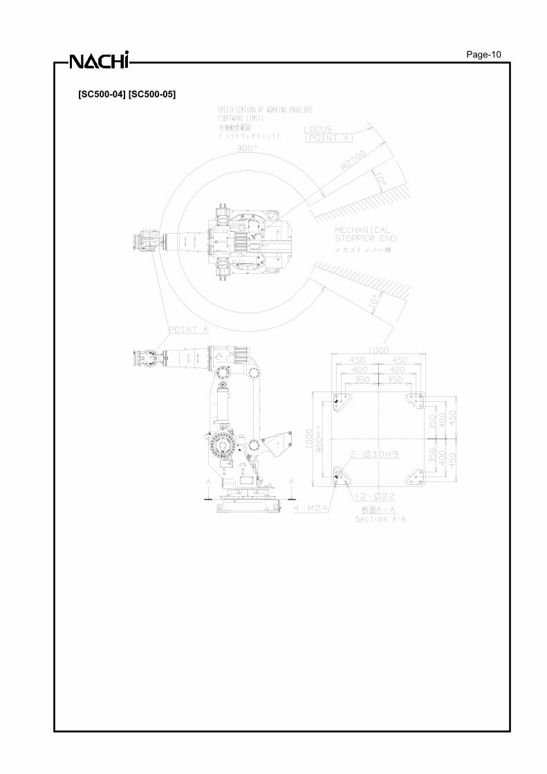
■ Installation dimension
Fix the robot swivel base for the robot installation.
WARNING
The mechanical stopper end is located in a position exceeding the specified operating
range (software limit) of axis 1 by 10°. To install the guard fence, refer to the figures in this section with consideration given to the wrist configuration and the shape of end effecter.
WARNING
On axis 1, 2 and 3, the robot operating range can be regulated for safety (optional function). Since optional parts (e.g. limit switches or additional stopper blocks) should be installed to enable this function, do not independently move the standard parts (e.g. stopper block).
WARNING
If mechanical stopper collides and robot stops, it’s possible that some parts are already damaged, for example, mechanical stopper is transformed or fixing bolts are broken. In this case, sufficient intensity and function can not been kept. Mechanical stopper and reduction gear of collided joint are needed to be replaced to the new one.
[SC400L-04] [SC400L-05]
Page-10
[SC500-04] [SC500-05]
Page-11
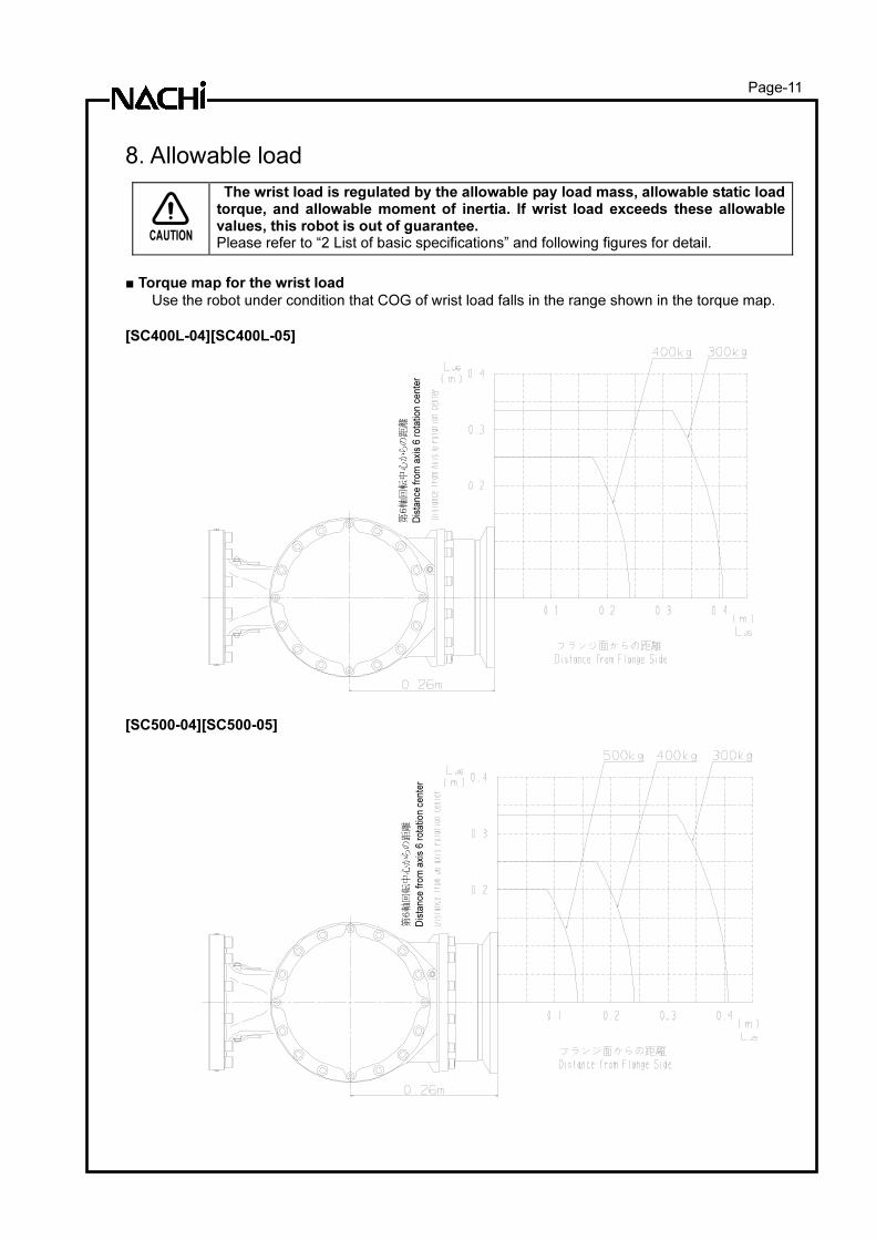
8. Allowable load
CAUTION
The wrist load is regulated by the allowable pay load mass, allowable static load torque, and allowable moment of inertia. If wrist load exceeds these allowable values, this robot is out of guarantee. Please refer to “2 List of basic specifications” and following figures for detail.
■ Torque map for the wrist load
Use the robot under condition that COG of wrist load falls in the range shown in the torque map.
[SC400L-04][SC400L-05]
[SC500-04][SC500-05]
第6
軸回
転中
心か
らの
距離
Dis
tan
ce
fro
m a
xis
6 r
ota
tio
n c
en
ter
第6
軸回
転中
心か
らの
距離
Dis
tan
ce
fro
m a
xis
6 r
ota
tio
n c
en
ter
Page-12
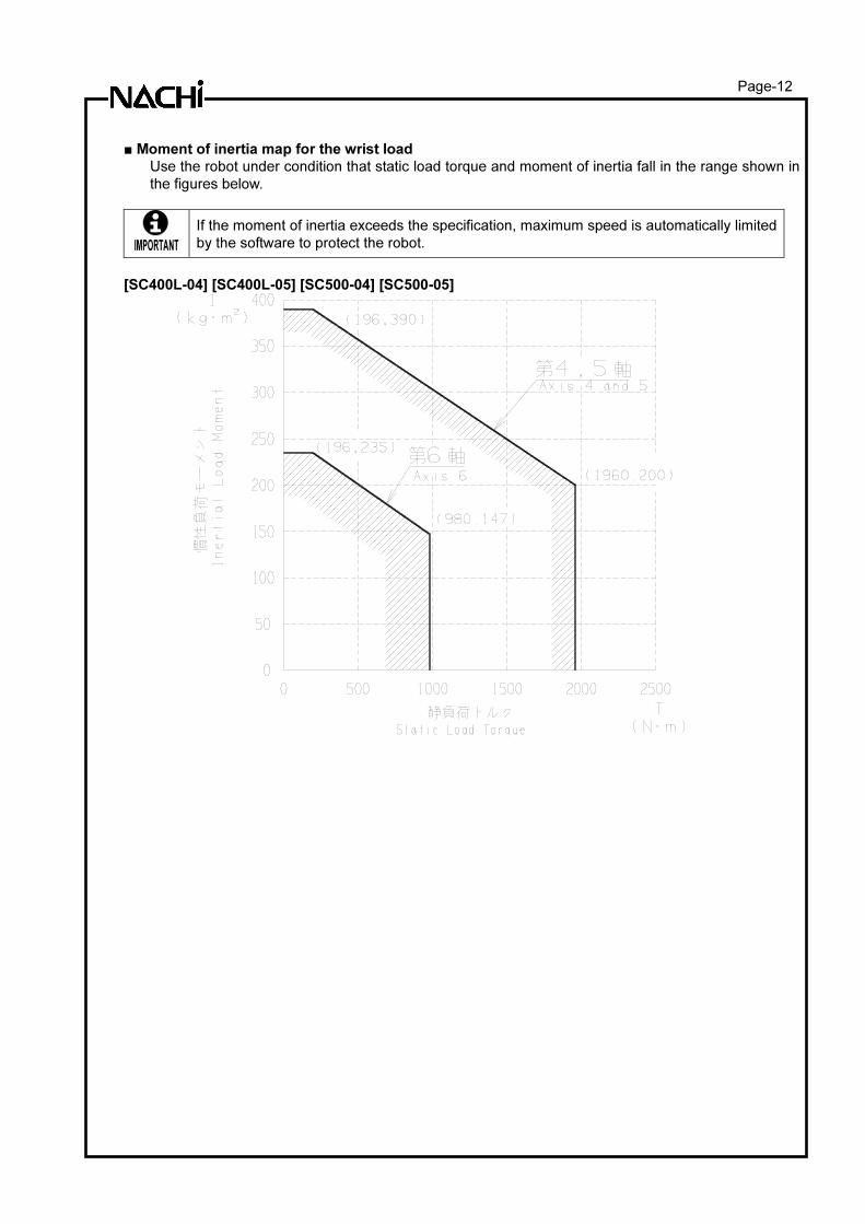
■ Moment of inertia map for the wrist load
Use the robot under condition that static load torque and moment of inertia fall in the range shown in
the figures below.
IMPORTANT
If the moment of inertia exceeds the specification, maximum speed is automatically limited
by the software to protect the robot.
[SC400L-04] [SC400L-05] [SC500-04] [SC500-05]
Page-13
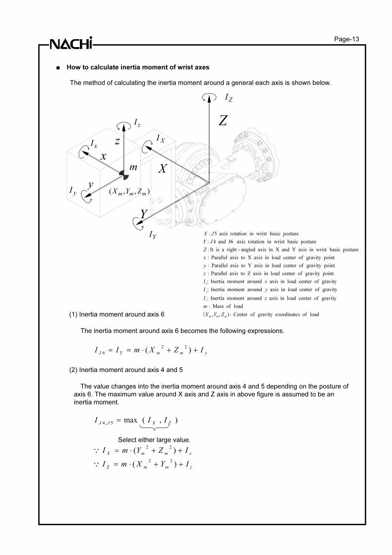
■ How to calculate inertia moment of wrist axes
The method of calculating the inertia moment around a general each axis is shown below.
(1) Inertia moment around axis 6
The inertia moment around axis 6 becomes the following expressions.
ymmYJ IZXmII ++⋅== )(22
6
(2) Inertia moment around axis 4 and 5
The value changes into the inertia moment around axis 4 and 5 depending on the posture of
axis 6. The maximum value around X axis and Z axis in above figure is assumed to be an
inertia moment.
),(max5,4 ZXJJ
III =
Select either large value.
zmmZ
xmmX
IYXmI
IZYmI
++⋅=
++⋅=
)(
)(
22
22
Q
Q
x
y
z
X
Z
Y
m
),,(mmm
ZYX yI
xI
ZI
zI
XI
YI
load of scoordinategravity ofCenter ),,
load of Mass
gravity ofcenter loadin axis aroundmoment Inertia
gravity ofcenter loadin axis aroundmoment Inertia
gravity ofcenter loadin axis aroundmoment Inertia
pointgravity ofcenter loadin axis Z toaxis Parallel
pointgravity ofcenter loadin axis Y toaxis Parallel
pointgravity ofcenter loadin axis X toaxis Parallel
posture basic in wrist axis Y and Xin axis angled-right a isIt :
posture basic in wrist rotation axis J6 and 4:
posture basic in wrist rotation axis 5:
:(
:
:
:
:
:
:
:
mmm
z
y
x
ZYX
m
zI
yI
xI
z
y
x
Z
JY
JX
Page-14
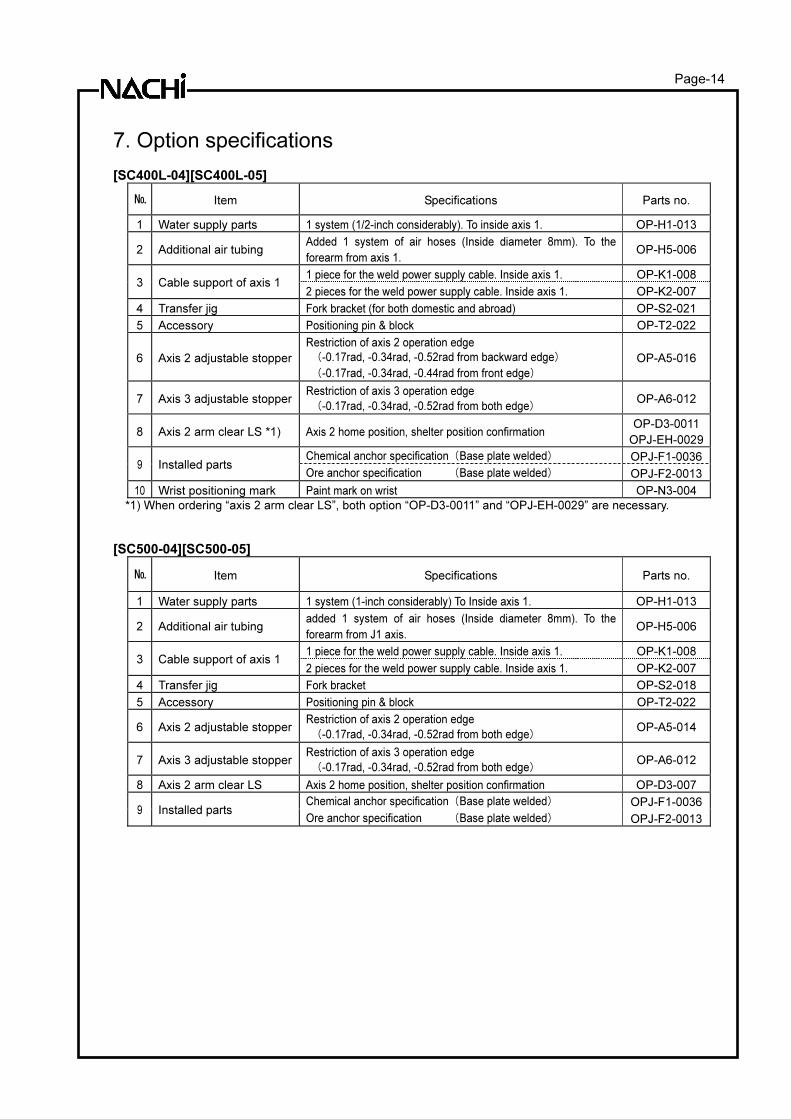
7. Option specifications [SC400L-04][SC400L-05]
№ Item Specifications Parts no.
1 Water supply parts 1 system (1/2-inch considerably). To inside axis 1. OP-H1-013
2 Additional air tubing Added 1 system of air hoses (Inside diameter 8mm). To the
forearm from axis 1. OP-H5-006
1 piece for the weld power supply cable. Inside axis 1. OP-K1-008 3 Cable support of axis 1
2 pieces for the weld power supply cable. Inside axis 1. OP-K2-007
4 Transfer jig Fork bracket (for both domestic and abroad) OP-S2-021
5 Accessory Positioning pin & block OP-T2-022
6 Axis 2 adjustable stopper
Restriction of axis 2 operation edge
(-0.17rad, -0.34rad, -0.52rad from backward edge)
(-0.17rad, -0.34rad, -0.44rad from front edge)
OP-A5-016
7 Axis 3 adjustable stopper Restriction of axis 3 operation edge
(-0.17rad, -0.34rad, -0.52rad from both edge) OP-A6-012
8 Axis 2 arm clear LS *1) Axis 2 home position, shelter position confirmation OP-D3-0011
OPJ-EH-0029
Chemical anchor specification (Base plate welded) OPJ-F1-00369 Installed parts
Ore anchor specification (Base plate welded) OPJ-F2-0013
10 Wrist positioning mark Paint mark on wrist OP-N3-004
*1) When ordering “axis 2 arm clear LS”, both option “OP-D3-0011” and “OPJ-EH-0029” are necessary.
[SC500-04][SC500-05]
№ Item Specifications Parts no.
1 Water supply parts 1 system (1-inch considerably) To Inside axis 1. OP-H1-013
2 Additional air tubing added 1 system of air hoses (Inside diameter 8mm). To the
forearm from J1 axis. OP-H5-006
1 piece for the weld power supply cable. Inside axis 1. OP-K1-008 3 Cable support of axis 1
2 pieces for the weld power supply cable. Inside axis 1. OP-K2-007
4 Transfer jig Fork bracket OP-S2-018
5 Accessory Positioning pin & block OP-T2-022
6 Axis 2 adjustable stopper Restriction of axis 2 operation edge
(-0.17rad, -0.34rad, -0.52rad from both edge) OP-A5-014
7 Axis 3 adjustable stopper Restriction of axis 3 operation edge
(-0.17rad, -0.34rad, -0.52rad from both edge) OP-A6-012
8 Axis 2 arm clear LS Axis 2 home position, shelter position confirmation OP-D3-007
Chemical anchor specification (Base plate welded) OPJ-F1-00369 Installed parts
Ore anchor specification (Base plate welded) OPJ-F2-0013
Page-15
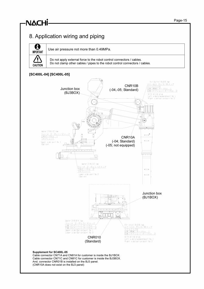
8. Application wiring and piping
IMPORTANT
Use air pressure not more than 0.49MPa.
CAUTION
Do not apply external force to the robot control connectors / cables. Do not clamp other cables / pipes to the robot control connectors / cables.
[SC400L-04] [SC400L-05]
Supplement for SC400L-05
Cable connector CN71A and CN81A for customer is inside the BJ1BOX.
Cable connector CN71C and CN81C for customer is inside the BJ3BOX.
And, connector CNR01B is installed on the BJ3 panel.
(CNR10A does not exist on the BJ3 panel)
Junction box (BJ1BOX)
CNR010(Standard)
CNR10A(-04; Standard)
(-05; not equipped)
CNR10B(-04,-05; Standard)Junction box
(BJ3BOX)
Page-16
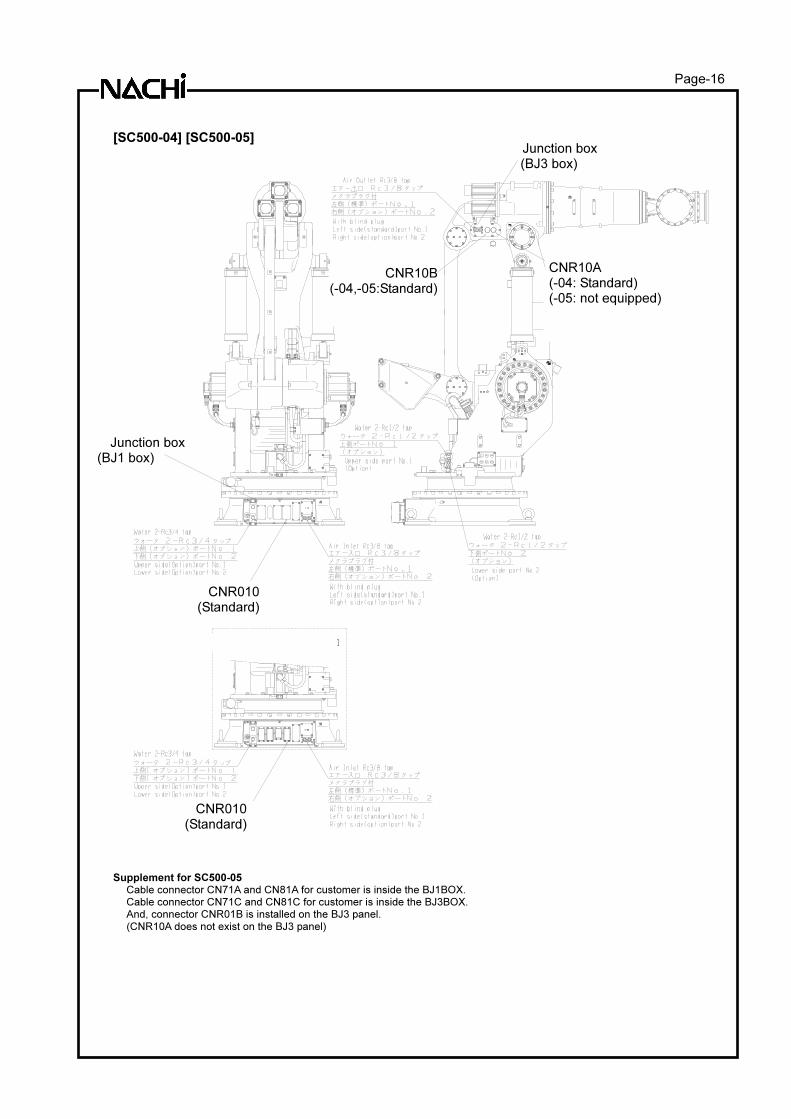
[SC500-04] [SC500-05]
Supplement for SC500-05 Cable connector CN71A and CN81A for customer is inside the BJ1BOX.
Cable connector CN71C and CN81C for customer is inside the BJ3BOX.
And, connector CNR01B is installed on the BJ3 panel.
(CNR10A does not exist on the BJ3 panel)
CNR10B(-04,-05:Standard)
CNR010(Standard)
CNR010 (Standard)
CNR10A (-04: Standard) (-05: not equipped)
Junction box (BJ1 box)
Junction box (BJ3 box)
Page-17
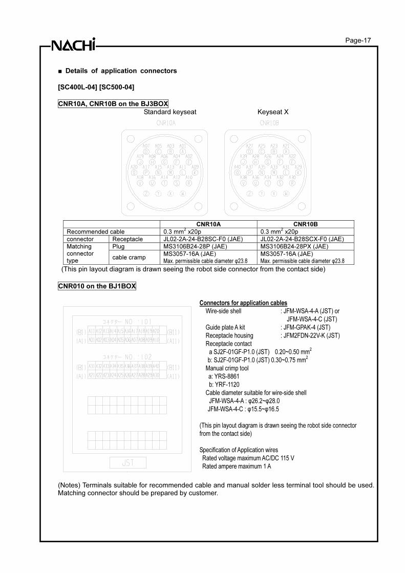
■ Details of application connectors
[SC400L-04] [SC500-04]
CNR10A, CNR10B on the BJ3BOX
Standard keyseat Keyseat X
CNR10A CNR10B
Recommended cable 0.3 mm2 x20p 0.3 mm
2 x20p
connector Receptacle JL02-2A-24-B28SC-F0 (JAE) JL02-2A-24-B28SCX-F0 (JAE)
Plug MS3106B24-28P (JAE) MS3106B24-28PX (JAE) Matching connector type
cable cramp MS3057-16A (JAE) Max. permissible cable diameter φ23.8
MS3057-16A (JAE) Max. permissible cable diameter φ23.8
(This pin layout diagram is drawn seeing the robot side connector from the contact side)
CNR010 on the BJ1BOX
Connectors for application cables
Wire-side shell : JFM-WSA-4-A (JST) or
JFM-WSA-4-C (JST)
Guide plate A kit : JFM-GPAK-4 (JST)
Receptacle housing : JFM2FDN-22V-K (JST)
Receptacle contact
a SJ2F-01GF-P1.0 (JST) 0.20~0.50 mm2
b: SJ2F-01GF-P1.0 (JST) 0.30~0.75 mm2
Manual crimp tool
a: YRS-8861
b: YRF-1120
Cable diameter suitable for wire-side shell
JFM-WSA-4-A : φ26.2~φ28.0
JFM-WSA-4-C : φ15.5~φ16.5
(This pin layout diagram is drawn seeing the robot side connector
from the contact side)
Specification of Application wires
Rated voltage maximum AC/DC 115 V
Rated ampere maximum 1 A
(Notes) Terminals suitable for recommended cable and manual solder less terminal tool should be used. Matching connector should be prepared by customer.
Page-18
[SC400L-05] [SC500-05]
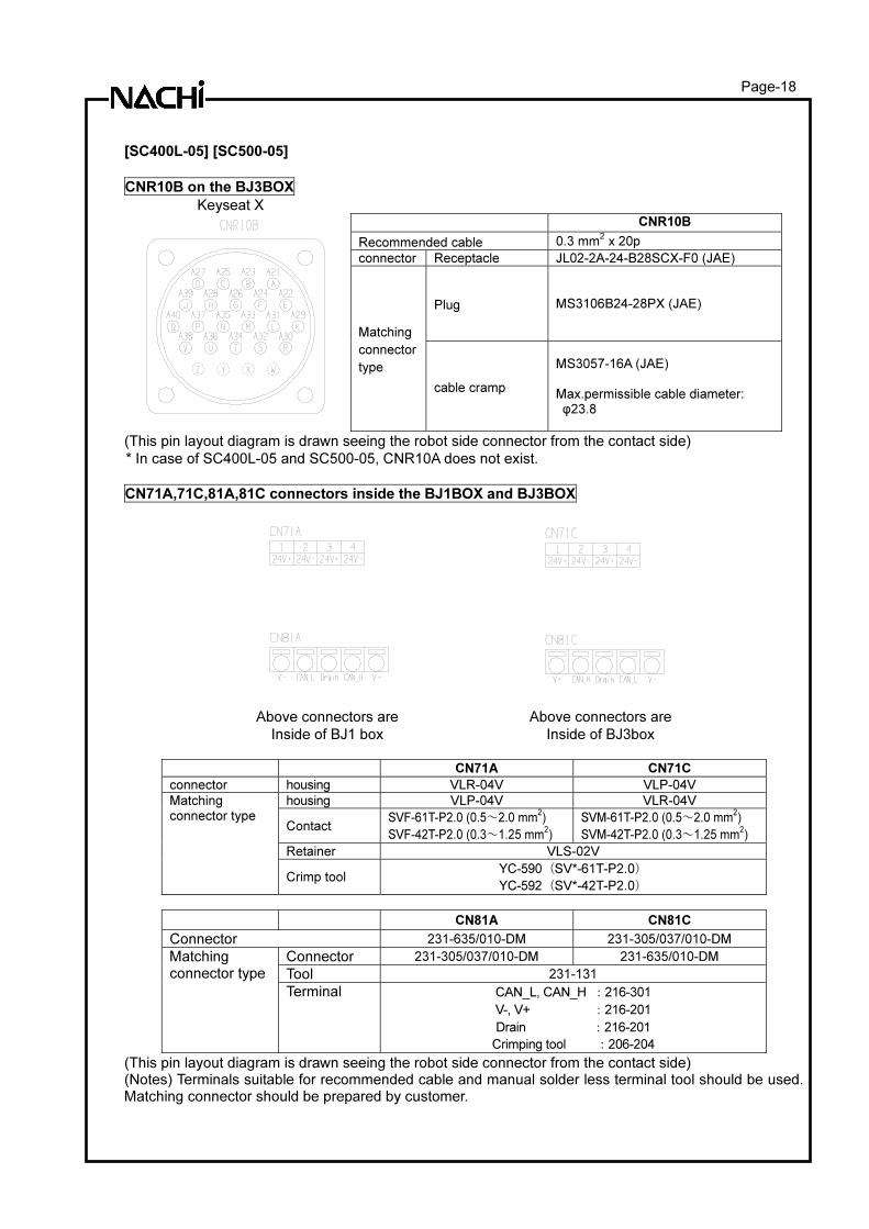
CNR10B on the BJ3BOX
Keyseat X
CNR10B
Recommended cable 0.3 mm2 x 20p
connector Receptacle JL02-2A-24-B28SCX-F0 (JAE)
Plug MS3106B24-28PX (JAE)
Matching
connector
type
cable cramp
MS3057-16A (JAE) Max.permissible cable diameter: φ23.8
(This pin layout diagram is drawn seeing the robot side connector from the contact side)
* In case of SC400L-05 and SC500-05, CNR10A does not exist.
CN71A,71C,81A,81C connectors inside the BJ1BOX and BJ3BOX
Above connectors are
Inside of BJ1 box
Above connectors are
Inside of BJ3box
CN71A CN71C
connector housing VLR-04V VLP-04V
housing VLP-04V VLR-04V
Contact SVF-61T-P2.0 (0.5~2.0 mm
2)
SVF-42T-P2.0 (0.3~1.25 mm2)
SVM-61T-P2.0 (0.5~2.0 mm2)
SVM-42T-P2.0 (0.3~1.25 mm2)
Retainer VLS-02V
Matching connector type
Crimp tool YC-590(SV*-61T-P2.0)
YC-592(SV*-42T-P2.0)
CN81A CN81C
Connector 231-635/010-DM 231-305/037/010-DM
Connector 231-305/037/010-DM 231-635/010-DM
Tool 231-131
Matching connector type
Terminal CAN_L, CAN_H :216-301
V-, V+ :216-201
Drain :216-201
Crimping tool :206-204
(This pin layout diagram is drawn seeing the robot side connector from the contact side) (Notes) Terminals suitable for recommended cable and manual solder less terminal tool should be used. Matching connector should be prepared by customer.
Page-19
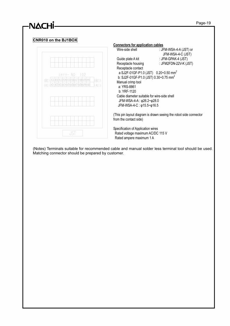
CNR010 on the BJ1BOX
Connectors for application cables
Wire-side shell : JFM-WSA-4-A (JST) or
JFM-WSA-4-C (JST)
Guide plate A kit : JFM-GPAK-4 (JST)
Receptacle housing : JFM2FDN-22V-K (JST)
Receptacle contact
a SJ2F-01GF-P1.0 (JST) 0.20~0.50 mm2
b: SJ2F-01GF-P1.0 (JST) 0.30~0.75 mm2
Manual crimp tool
a: YRS-8861
b: YRF-1120
Cable diameter suitable for wire-side shell
JFM-WSA-4-A : φ26.2~φ28.0
JFM-WSA-4-C : φ15.5~φ16.5
(This pin layout diagram is drawn seeing the robot side connector
from the contact side)
Specification of Application wires
Rated voltage maximum AC/DC 115 V
Rated ampere maximum 1 A
(Notes) Terminals suitable for recommended cable and manual solder less terminal tool should be used. Matching connector should be prepared by customer.
Page-20
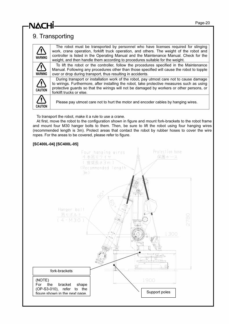
9. Transporting
WARNING
The robot must be transported by personnel who have licenses required for slinging work, crane operation, forklift truck operation, and others. The weight of the robot and controller is listed in the Operating Manual and the Maintenance Manual. Check for the weight, and then handle them according to procedures suitable for the weight.
WARNING
To lift the robot or the controller, follow the procedures specified in the Maintenance Manual. Following any procedures other than those specified will cause the robot to topple over or drop during transport, thus resulting in accidents.
CAUTION
During transport or installation work of the robot, pay utmost care not to cause damage to wirings. Furthermore, after installing the robot, take protective measures such as using protective guards so that the wirings will not be damaged by workers or other persons, or forklift trucks or else.
CAUTION
Please pay utmost care not to hurt the motor and encoder cables by hanging wires.
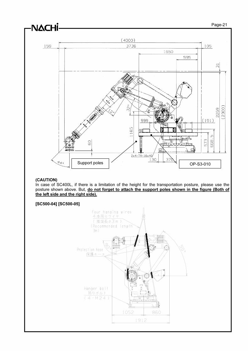
To transport the robot, make it a rule to use a crane.
At first, move the robot to the configuration shown in figure and mount fork-brackets to the robot frame
and mount four M30 hanger bolts to them. Then, be sure to lift the robot using four hanging wires
(recommended length is 3m). Protect areas that contact the robot by rubber hoses to cover the wire
ropes. For the areas to be covered, please refer to figure.
[SC400L-04] [SC400L-05]
(NOTE) For the bracket shape (OP-S3-010), refer to the figure shown in the next page.
fork-brackets
Support poles
Page-21
(CAUTION) In case of SC400L, if there is a limitation of the height for the transportation posture, please use the posture shown above. But, do not forget to attach the support poles shown in the figure (Both of the left side and the right side). [SC500-04] [SC500-05]
OP-S3-010 Support poles
Page-22
10. Delivery style (specification which contains a robot) 1. There are three styles as shown below
Condition Details
1 Delivery on the truck Robot is delivered on the truck near the entrance of customer’s plant. (Installation and test-run is not included)
2 Delivery after installation and test-run
Robot is installed and test-run is done. (Teaching with work piece is not included.)
3 Delivery after installation and teaching with work piece
After style 2, teaching with work piece is done.
Because the expense is different, which form to choose be sufficiently examined. 2. Operation and maintenance education The special spot operation guide and the special spot preservation guide are the outside of the estimation. Consult with each NACHI-FUJIKOSHI office for the details as for the schooling system.
11. Consuming power (Robot + Controller) 6.7 kVA (may vary according to the application and motion pattern.)
12. Paint color Standard color Controller cabinet Munsell 10GY9/1
Robot body Munsell 10GY9/1
13. Warranty Elapse of 1 year after delivery. (8 hours/day running)
The specification and externals described in this specifications might change without a previous notice for the improvement.

http://www.nachi-fujikoshi.co.jp/
JAPAN MAIN OFFICE Phone:
+81-3-5568-5245
Fax:
+81-3-5568-5236
Shiodome Sumitomo Bldg. 17F,
1-9-2 Higashi-Shinbashi
Minato-ku, TOKYO, 105-0021 JAPAN
NACHI NORTH AMERICA http://www.nachirobotics.com/
North America Headquarters Phone: 248-305-6545 Fax: 248-305-6542 22285 Roethel Drive, Novi, Michigan 48375 U.S.A.
Greenville Service Office Use 248-305-6545 Use 248-305-6542 South Carolina, U.S.A.
San Antonio Service Office Use 248-305-6545 Use 248-305-6542 Texas, U.S.A.
Kentucky Branch Office Phone: 502-695-4816 Fax: 502-695-4818 116 Collision Center Drive, Suite A, Frankfort, KY 40601 U.S.A
Training Office Phone: 248-334-8250 Fax: 248-334-8270 22213 Roethel Drive, Novi, Michigan 48375 U.S.A.
Toronto Branch Office Phone: 905-760-9542 Fax: 905-760-9477 89 Courtland Avenue, Unit 2, Vaughan,
Ontario L4K3T4 CANADA
Mexico Branch Office Phone :
+52-555312-6556
Fax:
+52-55-5312-7248
Urbina # 54, Parque Industrial Naucalpan,
Naucalpan de Juarez, 53370, Estado de México, MEXICO
Saltillo Service Office Phone :
+52-844416-8053
Fax:
+52-844416-8053
Canada 544 Privada Luxemburgo
C. P. 25230, Saltillo, Coahuila, MEXICO
NACHI ROBOTIC EUROPE
Germany http://www.nachi.de/
Nachi Europe GmbH
Phone:
+49-(0)2151-65046-0
Fax:
+49-(0)2151-65046-90 Bischofstrasse 99, 47809, Krefeld,GERMANY
United Kingdom http://www.nachi.co.uk/
Nachi U.K. LTD. Phone:
+44-(0)121-250-1895
Fax:
+44-(0)121-250-1899
Unit 7, Junction Six Industrial Estate, Electric Avenue,
Birmingham B6 7JJ, U.K.
Czech Republic
Nachi Europe Phone:
+ 420-255-734-000
Fax:
+420-255-734-001 Prague 9, VGP Park, Czech republic
NACHI ROBOTIC ASIA
Korea http://www.nachi-korea.co.kr/
Korea Phone:
+82-(0)2-469-2254
Fax:
+82-(0)2-469-2264
2F Dongsan Bldg.
276-4, Sungsu 2GA-3DONG, Sungdong-ku,
Seoul 133-123, KOREA
Copyright NACHI-FUJIKOSHI CORP. Robot Division
1-1-1, FUJIKOSHIHONMACHI, TOYAMA CITY, JAPAN 930-8511
Phone +81-76-423-5137
Fax +81-76-493-5252
NACHI-FUJIKOSHI CORP. holds all rights of this document. No part of this manual may be photocopied or reproduced in any from without prior written consent from NACHI-FUJIKOSHI CORP. Contents of this document may be modified without notice. Any missing page or erratic pagination in this document will be replaced.
In case that an end user uses this product for military purpose or production of weapon, this product may be liable for the subject of export restriction stipulated in the Foreign Exchange and Foreign Trade Control Law. Please go through careful investigation and necessary formalities for export.
Original manual is written in Japanese.
©