Technical information - DHM Tools
88
-
Upload
khangminh22 -
Category
Documents
-
view
3 -
download
0
Transcript of Technical information - DHM Tools


Technical information
Discover powRgrip® 268ER clamping system 270micRun® System 272XL vibration damping 274secuRgrip® 276Mastering both wet and dry applications 278Cryogen cooling 280powRgrip® System nose diameter comparison 282Presetting range of powRgrip® collets 284Assembly instructions for ER and MR collets 290Instructions for correct clamping of tool shanks 291Increasing collet and tool life 292Recommended tightening torque (ER / MR clamping nuts) 293ER collets dimensions 295Dimensions for ER collet cavities and clamping nuts 298Tapping collets ER-GB 299 Tapping collets PCM ET1 300Microbore collets ER-MB 300
Reduction sleeves 301Spindle interface norms 304HSK forms and their key characteristics 305HSK interface 306Balancing 308DIN 69888:2008-09 315Milling strategies 316Troubleshooting milling / drilling / reaming / tapping 318Formulas for cutting data 322Cutting speed conversion table for threading 323Hardness chart 324Conversion chart / inch-metric 325Form and position tolerances in practice 326Tolerance charts 330Thread tolerances 331Core hole diameters for thread cutting 332Shank diameter of taps 336Material comparison chart 337Terminology 351

>20,000x
≤3μm
SIMPLETool is clamped in 8 seconds by pushingonly one single button.
SAFENo heat up – high clamping force.
powRgrip®
The tool clamping system of today and the future.
8 sec
Tool ready for use in 8 seconds.
Total system runout TIR�������������
Excellent vibration damping.
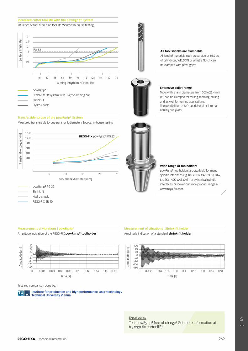
Maximum clamping force and low runout, even after 20,000 tool changes.
Meeting high machining demandsThe powRgrip® System provides excellent runout, high vibration damping as well as easy and secure handling for demanding high-speed milling and drilling.
Power and precision combined An outstanding tool runout is one � ������������������������������������������������������ ��
268 Technical information
���
����
����
����
�!
3
2.5
2
1.5
1
0.5
16 32 48 64 80 96 112 128 144 160 176
Cutting length [m] / tool life
powRgrip®
REGO-FIX ER System with Hi-Q® clamping nut
�����"#��
Hydro chuck
Increased cutter tool life with the powRgrip® System
$��������� ����������������������� ��%�Source: In-house testing
Transferable torque of the powRgrip® System
Measured transferable torque per shank diameter / Source: In-house testing
Ra 1.6
REGO-FIX powRgrip® PG 32
Tran
sfer
able
torq
ue [N
m] 1200
1000
800
600
400
200
5 10 15 20 25
Tool shank diameter [mm]
powRgrip® PG 32
�����"#��
Hydro chuck
REGO-FIX ER 40
Measurement of vibrations | powRgrip®
Amplitude indication of the REGO-FIX powRgrip® toolholder
���������� ��������� �������������� ����
Amplitude indication of a standard ���������� ����
Test and comparison done by:
0 0.002 0.004 0.06 0.08 0.1 0.12 0.14 0.16 0.18
Time [s]
1208040
0-40-80
-120-160
0 0.002 0.004 0.06 0.08 0.1 0.12 0.14 0.16 0.18
Time [s]
1208040
0-40-80
-120-160
Am
plitu
de [μ
m]
Am
plitu
de [μ
m]
Institute for production and high-performance laser technologyTechnical University Vienna
Expert advice
Test powRgrip® free of charge! Get more information at ��������#����%������ ��
All tool shanks are clampable
All kind of materials such as carbide or HSS as
of cylindrical, WELDON or Whistle Notch can
be clamped with powRgrip®.
Extensive collet range
Tools with shank diameters from 0.2 to 25.4 mm
(1“) can be clamped for milling, reaming, drilling
and as well for turning applications.The possibilities of MQL, peripheral or internal cooling are given.
���������� ��� �� ������
powRgrip®-toolholders are available for many
spindle interfaces e.g. REGO-FIX CAPTO, BT, BT+,
SK, SK+, HSK, CAT, CAT+ or cylindrical spindle
interfaces. Discover our wide product range at
'''�����#������
269 Technical information

������� �� �������������*�����;<=#>$?�����������@���@�����;������������JUVYZ�������"���� machining world by storm. With the DIN 6499 standardization twenty years later, the REGO-FIX ER collet became the industry standard. Today, the ER System is still the most used toolholding system worldwide.
Extend tool life with the REGO-FIX ER range
$��������� ����������������������� ��%�������\�$�#�������������
High vibration-damping results in longer tool life and ^������� ����������
The widest ER product range: clamps all diameters from 0.2 mm – 36 mm.
Safe and accurate toolholding of all shank types and materials.
=������@�������^������ ������� with all tool types.
High quality matters An outstanding tool runout is one � ������������������������������������������������������ ��
Tool
life
[ %
]
180
160
140
120
100
80
60
40
20
2.5 5 7.5 10 12.5 15 17.5 20 22.5 25 27.5
Runout [μm]
Low quality productsMachining excellence
REGO-FIX Standard collets
REGO-FIX Ultraprecision collets
270 Technical information

Successful clamping since 1972Combine our ER toolholders with our ER collets to ensure maximum precision and balance to maximize your tool life. All our products bear the REGO-FIX triangle – our seal for outstanding Swiss quality.
������������������! "#$��%&��!
DIN 6499
> ' L ISO 15488 B �ER std. �ER-UP �MR
1 1.6 6 0.015 0.01 0.005 0.002
1.6 3 10 0.015 0.01 0.005 0.002
3 6 16 0.015 0.01 0.005 0.002
6 10 25 0.015 0.01 0.005 0.002
10 18 40 0.02 0.01 0.005 0.002
18 26 50 0.02 0.01 0.005 0.002
26 36 60 0.025 0.01 0.005 0.002
�����������
Key advantages
Rely on the original�����(����������
The slot design allows for a wide clamping rangewith best runout TIR along the entire clamping range.
Broad range of products
We offer sizes from ER 8 up to ER 50 and diametersfrom 0.2 mm up to 36 mm.
)��� �*+�/� ���(�����������
Improve your runout with up to 20 % more clamping length in smaller diameters.
���(����� �����:����� ���������
The compatibility of the entire system results in maximum precision, balance and tool life.
���������������;���������������:��<������������� Swiss people are known to be humble and conservative: All our measuring data are to be considered as maximum values. Many other manufacturers are showing the common
measured total internal runout (TIR average). With us, you get maximum guaranteed values – To your advantage most of the values are even considerably lower.
Runout TIR of ER standard, ER-UP and MR collets
�
�
j�{������
271 Technical information

Every micron countsClosing the gap between the powRgrip® and the ER System,the micRun®����������� �����'��������������������������� ��������
Swiss high precision An excellent runout accuracy paired with superior vibration damping, not only increases your machining quality, but enhances your overall productivity. It also increased your tool life, thus successfully lowering your ��������������*��������������������������� ������������ x D, the micRun®�������������@�����������^�������� �����������������accuracy. This is why micRun® is the ideal system for all micro machining applications and is successfully used in industries like watchmaking or medical engineering. In addition, our unique collet-locking system retains the collet safely inside the nut. This minimizes your risk of faulty operations or possible damages which may occur if the collet accidentally falls ������������@��|�������������^������� �����������#���"����system is the tool-free removal of the collet.
≤3μm
High vibration-damping results in longer tool life and best surface ������
}������������}$���������������� Designed for high-speed cutting.
Silent and low vibration due to grooveless clamping nut.
272 Technical information

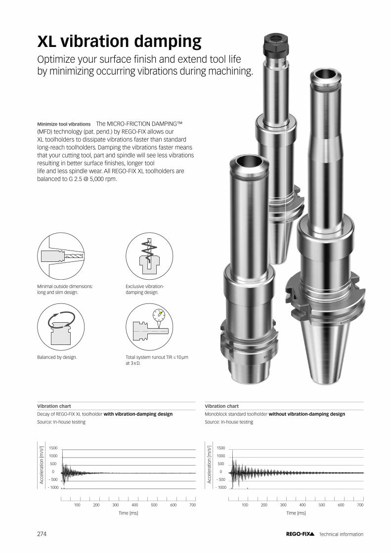
Minimize tool vibrations The MICRO-FRICTION DAMPING™ (MFD) technology (pat. pend.) by REGO-FIX allows our XL toolholders to dissipate vibrations faster than standard long-reach toolholders. Damping the vibrations faster means that your cutting tool, part and spindle will see less vibrations resulting in better surface �������Z������������� life and less spindle wear. All REGO-FIX XL toolholders are balanced to G 2.5 @ 5,000 rpm.
XL vibration damping=���������������� ������������@�����@�������� �� by minimizing occurring vibrations during machining.
Acc
eler
atio
n [m
/s2 ] 1500
1000
500
0
- 500
- 1000
100 200 300 400 500 600 700
Time [ms]
Vibration chart
Decay of REGO-FIX XL toolholder with vibration-damping design
Source: In-house testing
Vibration chart
Monoblock standard toolholder without vibration-damping design
Source: In-house testing
Acc
eler
atio
n [m
/s2 ] 1500
1000
500
0
- 500
- 1000
100 200 300 400 500 600 700
Time [ms]
}�������������������}$����J����at 3 x D.
Minimal outside dimensions: long and slim design.
Exclusive vibration- damping design.
Balanced by design.
274 Technical information
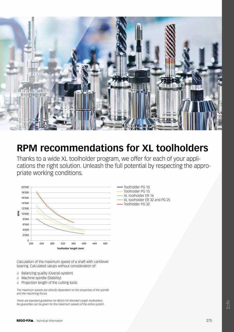
Calculation of the maximum speed of a shaft with cantilever bearing. Calculated values without consideration of:
/ / Balancing quality (Overall-system)/ / Machine spindle (Stability)/ / Projection length of the cutting tools
��� ������������� ����������������������������������������������������� ������� ��������������
���� ����� �� ���������������������!"#$%�%�������������������������&���� � ������ ��'����(����������� ���������������������������������
RPM recommendations for XL toolholdersThanks to a wide XL toolholder program, we offer for each of your appli- cations the right solution. Unleash the full potential by respecting the appro-priate working conditions.
0
2'000
4'000
6'000
8'000
10'000
12'000
14'000
16'000
18'000
20'000
200 240 280 320 360 400 440 480
Dre
hzah
l (¹/m
in)
Halterlänge (mm)
Toolholder PG 10 Toolholder PG 15 XL toolholder ER 16 XL toolholder ER 32 and PG 25 Toolholder PG 32
RP
M
Toolholder length (mm)
275 Technical information

1.1.4
C ������ ��J++�/����� ����� ��(�� With our innovative secuRgrip® solution, we offer a total tool pullout protection for the ER and powRgrip® System.
}����@�@�������� �����@���������
SecuRgrip® is available for all standard ������'����*��@��������J����Y�������Z� '��������@@����������@����������
Increase productivity through process reliability.

Length alterations can lead to damage of the workpiece. Prevent workpiece damage by using REGO-FIX secuRgrip®.
������(���������� ������(����� to-handle workpieces
Full protection where you need it The secuRgrip® threaded ����������@������@�������������������'������*��@�������� This way you can use the tool of your choice. In combination with our secuRgrip® collet, we offer the ultimate tool pullout protection at a competitive price.
Avoiding length alterations caused by tool pullout results in improved process reliability and ultimately improves your overall machining productivity. Our secuRgrip® solution is available for ER 32 and ER 40 as well as for PG 15, PG 25 and PG 32 – just the right sizes when it comes to rough machining.
/ / No additional costs for replacing damaged tools, thanks to ER and PG secuRgrip®
/ / �����@���������� ��������������"�����������@/ / Extra protection for worry-free machining, especially
with expensive work pieces
Tool pullout occurs secuRgrip® prevents tool pullout
Expert advice
secuRgrip® is available for ER and powRgrip®.
277 Technical information

Mastering both wet and dry applications*��� ���� ����������������� ����������������������������������@� different work materials to maximize your machining.
��������������������������@� ���������������������techniques and work materials, such as carbon, high-tensile plastics or wood.
Pros
/ / Reduced initial machine investment costs/ / Simple and easy cleaning/ / Clear sight on point of action between tool
and workpiece
Cons
/ / Inadequate heat dissipation can lead to a reduced tool life
/ / Increased tooling costs due to earlier wear and tear/ / Extended production cycles due to slower
possible production speed
The cutting edge is subject to thermal strains. Wet machining thus helps to regulate the impact of high heat that occurs during milling, ultimately protecting the tool against total tool failure.
Pros
/ / Fast and effective heat dissipation/ / Improved surfaces thanks to lubrication
of cutting edge/ / Clean and easy chip removal/ / Production cycles can be increased leading
to an overall increase of productivity/ / Lowered tool costs
Cons
/ / Additional costs for the acquisition of a pump/ / Limited view on point of action/ / Wet surroundings may present as an ideal
bacteria breeding ground
Wet machiningDry machining
278 Technical information

Supplying the right amount of coolant to where it matters
Key features of peripheral cooling
/ / Coolant is fed along the side of the tool to the cutting edge/ / Can be used for moderate cavities/ / Achieve peripheral cooling with reCool® and the use
� ������������������@��"����%�;������<#�>�������
W�:���������� ���%������Y ��( ���
/ / Universal application possibilities/ / Problems may arise with deep cavities/ / Reduction of tool life because cooling is not right
on the cutting edge/ / ��^�������������@��������/ / Limited adjustment of nozzles due to different tool
lengths and diameters
;����������@��������
Peripheral cooling
Internal cooling
Key features of internal cooling
/ / Precise cooling at the cutting edge and improved chip removal
/ / Particularly suitable for deep cavities/ / Deep hole drilling and threading/ / Lubrication of cutting edge and cooling/ / Best surface quality/ / Achieve internal cooling with reCool® and the use
of our sealing disk DS / ER
279 Technical information

Cryogen: Coolant at the right spot
COOLCO2 cools the cutting edge in a safe and clean way, thanks to powRgrip® with an optimum dosage.
CLEANNo contamination at all, therefore no necessity to do additional cleaning of the workpiece afterwards.
CRYO-powRgrip®
PG-CRYO collets offer the latest tool cooling technology for a clean chipping of workpieces (i.e. medical industries).
>20,000x
≤3μm
8 sec
Tool ready for use in8 seconds with PGU 9500.
Total system runout TIR��������������
Excellent vibration damping.
Maximum clamping forceand low runout, even after 20,000 tool changes
280 Technical information

ER toolholderTypical tool clamping system, with the risk of icing of the holder, due to the gaseous state behaviour of CO2.
PG-CRYO toolholderThe cooling medium will be directly led to the cutting edge through the cutting tool. The CO2 expands at the cutting �@�����@������������'������@������� ���������@�������chipping
For internal coolingFor peripheral external cooling
\��
����
"������
� �
State of aggregation diagram C02 ]����� ���$^_�� <$����®
/ / Perfect guidance of the cooling medium to the cutting edge
/ / Tool life increase/ / Productivity increase, due to higher cutting parameters/ / ���������� ������������/ / ���@��������� ����������������@����������/ / No necessity of workpiece cleaning/ / 100 % recycling of the chips
SOLID
LIQUID
SUPER-CRITICAL
GAS
The major difference of toolholding systemsSolution: reducing of the condensation space
281 Technical information

Standard nose diameter comparisonØ
24
Ø15
.5Ø
10Ø
16Ø
22Ø
33
Ø40
Ø50
Ø43
Ø28
PG / SG 15
Ø46
PG / SG 25
Ø55
PG / SG 32
powRgrip® System and secuRgrip® nose diameter comparison
PG 32Collet diameters:6.0 – 25.0 mm / 1/4 – 1"
Collet options:Std, CF, L, S, SG
PG 15Collet diameters:3.0 – 12.0 mm / 1/8 – 1/2"
Collet options:Std, CF, L, S, SG, T, TAP
PG 25Collet diameters:3.0 – 20.0 mm / 1/8 – 3/4"
Collet options:Std, CF, L, S, SG, T, TAP
PG 10Collet diameters:0.2 – 6.0 mm / 1/16 – 1/4"
Collet options:Std, CF, S, MB
PG 6Collet diameters:0.2 – 4.0 mm / 1/16 – 1/8
Collet options:Std, CF, S, MB
secuRgrip® nose diameter comparison
282 Technical information


Presetting range of powRgrip® collets
PG 6 / -CF PG 6-S PG 10 / -CF PG 10-S \{�J}�~���C�~�"� PG 15-S \{�J}���� PG 25 / -CF
D D ���! ���! ���! ���! ���! ���! ���! ���!
�! ���(�! min. max. min. max. min. max. min. max. min. max. min. max. min. max. min. max.
0.2–1.0 – 21.5 26.5* – – 20 24* – – – – – – – – – –
1.5 – 23.5 26.5* – – 16 20* – – – – – – – – – –
– 1/16" 23.5 26.5* – – 16 20* – – – – – – – – – –
2.0 – 24 26.5 – – 25 30 – – – – – – – – – –
2.5 – 24 26.5* – – 25 30 – – – – – – – – – –
3.0 – 24 26.5 17 20 25 30 20.5 26 25 30 – – – – 25 32,5
– 1/8" 24 26.5 17 20 25 30 20.5 26 25 30 18 25 – – 25 32,5
3.5 – – – – – 25 30 – – 25 30 – – – – 25 32,5
4.0 – 23.5 26.5* – – 25 30 20.5 26 25 30 18 25 25 53 25 32,5
4.5 – – – – – 25 30 – – 25 30 – – – – 25 32,5
– 3/16" – – – – 25 30 20.5 26 25 30 18 25 – – 25 32,5
5.0 – – – – – 25 30 – – 25 30 18 25 25 53 25 32,5
5.5 – – – – – 25 30 – – 25 30 – – – – 25 32,5
6.0 – – – – – 30 35 23.5 29 33 38 26 33 33 53 33 40.5
– 1/4" – – – – 30 35 23.5 29 33 38 26 33 33 53 33 40.5
7.0 – – – – – – – – – 33 38 – – – – 33 40.5
– 5/16" – – – – – – – – 33 38 26 33 33 53 33 40.5
8.0 – – – – – – – – – 33 38 26 33 33 53 33 40.5
9.0 – – – – – – – – – 33 38 – – – – 33 40.5
– 3/8" – – – – – – – – 37 40.5 31 38 37 53 37 44.5
10.0 – – – – – – – – – 37 40.5 31 38 37 53 37 44.5
11.0 – – – – – – – – – – – – – – – 37 44.5
– 7/16" – – – – – – – – – – – – – – 37 44.5
12.0 – – – – – – – – – 41.5* 45* – – – – 42 49.5
– 1/2" – – – – – – – – 41.5* 45* – – – – 42 49.5
13.0 – – – – – – – – – – – – – – – 42 49.5
14.0 – – – – – – – – – – – – – – – 42 49.5
– 9/16" – – – – – – – – – – – – – – 42 49.5
15.0 – – – – – – – – – – – – – – – 42 49.5
– 5/8" – – – – – – – – – – – – – – 45.5 50
16.0 – – – – – – – – – – – – – – – 45.5 50
18.0 – – – – – – – – – – – – – – – 45.5 50
– 3/4" – – – – – – – – – – – – – – 47.5 50
20.0 – – – – – – – – – – – – – – – 47.5 50
22.0 – – – – – – – – – – – – – – – – –
– 7/8" – – – – – – – – – – – – – – – –
25.0 – – – – – – – – – – – – – – – – –
– 1" – – – – – – – – – – – – – – – –
)*#����� ( �� '��� ))+�"��,���������������,
284 Technical information

Presetting range of powRgrip® collets
PG 25-S \{�*}���� PG 32 / -CF PG 32-S \{��*����
D D ���! ���! ���! ���! ���!
�! ���(�! min. max. min. max. min. max. min. max. min. max.
0.2–1.0 – – – – – – – – – – –
1.5 – – – – – – – – – – –
– 1/16" – – – – – – – – – –
2.0 – – – – – – – – – – –
2.5 – – – – – – – – – – –
3.0 – – – – – – – – – – –
– 1/8" 18 25 – – – – – – – –
3.5 – – – – – – – – – – –
4.0 – 18 25 – – – – – – – –
4.5 – – – – – – – – – – –
– 3/16" 18 25 – – – – – – – –
5.0 – – – – – – – – – – –
5.5 – – – – – – – – – – –
6.0 – 26 33 33 65 33.5 40.9 – – – –
– 1/4" 26 33 33 65 33.5 40.9 – – – –
7.0 – – – – – 33.5 40.9 – – – –
– 5/16" 26 33 33 65 33.5 40.9 – – – –
8.0 – 26 33 33 65 33.5 40.9 – – – –
9.0 – – – – – 33.5 40.9 – – – –
– 3/8" 30 38 37 65 35.5 44.9 – – – –
10.0 – 30 38 37 65 35.5 44.9 – – – –
11.0 – – – – – 35.5 44.9 – – – –
– 7/16" – – – – 35.5 44.9 – – – –
12.0 – 35 43 42 65 40.5 49.9 32 40.5 40.5 69
– 1/2” 35 43 42 65 40.5 49.9 32 40.5 40.5 69
13.0 – – – – – 40.5 49.9 – – – –
14.0 – 35 43 42 65 40.5 49.9 35 43 40.5 69
– 9/16" – – – – 40.5 49.9 – – – –
15.0 – – – – – 40.5 49.9 – – – –
– 5/8" 38 46 45.5 65 43.5 52.9 38 46 – –
16.0 – 38 46 45.5 65 43.5 52.9 35 43.5 43.5 69
18.0 – – – – – 43.5 52.9 – – – –
– 3/4" 40 47.5 47.5 65 45.5 54.9 37 45.5 45.5 69
20.0 – 40 47.5 47.5 65 45.5 54.9 37 45.5 45.5 69
22.0 – – – – – 45.5 54.9 – – – –
– 7/8" – – – – 45.5 54.9 – – – –
25.0 – – – – – 49.5 58 41 49.5 49.5 69
– 1" – – – – 49.5 58 41 49.5 49.5 69
)*#����� ( �� '��� ))+�"��,���������������,
�
#
PG / PG-CF / PG-S / PG-L
285 Technical information
�$
�
�(
#
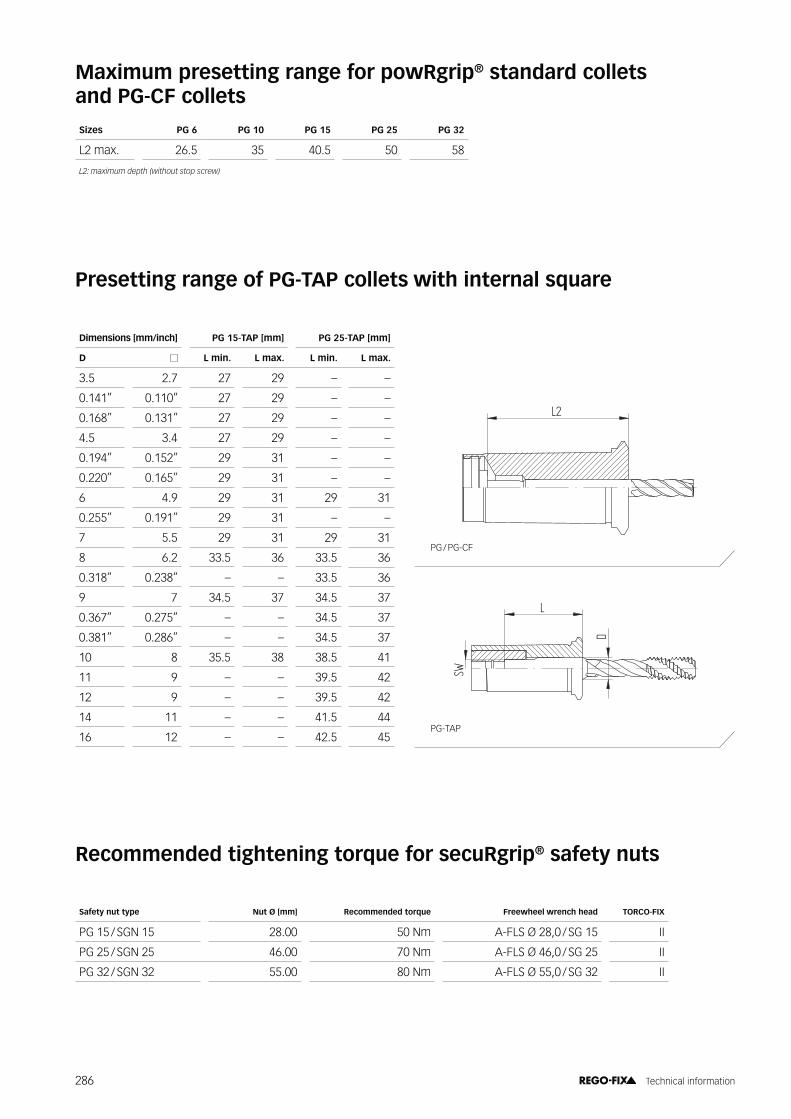
Maximum presetting range for powRgrip® standard collets and PG-CF collets
Presetting range of PG-TAP collets with internal square
Recommended tightening torque for secuRgrip® safety nuts
Sizes PG 6 PG 10 PG 15 PG 25 PG 32
L2 max. 26.5 35 40.5 50 58
�-.�� �����������/,���������������,0
Safety nut type Nut ���! Recommended torque Freewheel wrench head TORCO-FIX
PG 15 / SGN 15 28.00 ����� A-FLS Ø 28,0 / SG 15 II
PG 25 / SGN 25 46.00 70 Nm A-FLS Ø 46,0 / SG 25 II
PG 32 / SGN 32 55.00 80 Nm A-FLS Ø 55,0 / SG 32 II
PG / PG-CF
PG-TAP
����� ���~�(�! \{�J}�"�\��! \{�*}�"�\��!
D L min. L max. L min. L max.
3.5 2.7 27 29 – –
0.141” 0.110” 27 29 – –
0.168” 0.131” 27 29 – –
4.5 3.4 27 29 – –
0.194” 0.152” 29 31 – –
0.220” 0.165” 29 31 – –
6 4.9 29 31 29 31
0.255” 0.191” 29 31 – –
7 5.5 29 31 29 31
8 6.2 33.5 36 33.5 36
0.318” 0.238” – – 33.5 36
9 7 34.5 37 34.5 37
0.367” 0.275” – – 34.5 37
0.381” 0.286” – – 34.5 37
10 8 35.5 38 38.5 41
11 9 – – 39.5 42
12 9 – – 39.5 42
14 11 – – 41.5 44
16 12 – – 42.5 45
286 Technical information


The unbeatable advantages from the inventor of the ER collet
���������(�� ����������
/ / Includes friction-bearing for higher clamping force/ / Available with sealing disk for coolant through tools/ / Mini nut with minimal external diameter/ / Clamping nut for high rpm/ / ;��������������@�@�������������� ���������������"�Z
ERA Zero-Z® toolholder and live tooling/ / Slip-off proof mini clamping nut intRlox® for safe
assembling
Key advantages
ER SystemCollet locking system
Retains collet in nut for easier assembly.
Balancing
Ideal for high-speed applications.
Higher transferable torque
Lower frictional forces resulting in up to 80 % higher gripping force over standard non-treated clamping nuts. With friction bearing nut up to 125 %.
Protection against corrosion
With a special surface treatment for longer life.
Optimal contour
Rounded thread start prevents damaging of colletson tool changes.
Max
. Bal
anci
ng q
ualit
y 60
50
40
30
20
10
Hi-Q®/ Hi-Q®/ Hi-Q®/ Hi-Q®/ Hi-Q®/ Hi-Q®/ ER 11 ER 11 ER 16 ER 16 ER 20 ER 20 ER 25 ER 25 ER 32 ER 32 ER 40 ER 40
Competitor clamping nuts
REGO-FIX clamping nuts
Balancing quality overview
REGO-FIX clamping nuts vs. competitor nuts / Source: In-house testing
Tran
sfer
able
torq
ue 250 %
200 %
150 %
100 %
50 %
Competitor REGO-FIX Hi-Q®/ ER REGO-FIX Hi-Q®/ ERB
ER uncoated
Torque comparison of different clamping nuts
REGO-FIX Hi-Q® / ER andHi-Q® / ERB vs. competitor nuts
Source: In-house testing
J++�/
J�+�/**}�/
Swiss quality standard
Our products marked Swiss made are manufactured at our headquarters in Tenniken, Switzerland.
289 Technical information

Collet groove
Eccentric ring
Mark on bottom
Mark on bottom
Assembling
Disassembling
Collet groove
Eccentric ring
Mark on bottom
Face contact
Assembly instructions for ER and MR collets
Collets ER 11 – ER 50 and MR 11 – MR 32 (with collet locking system)
Assembling Insert groove of the collet into eccentric ring of the clamping nut at the mark on the bottom of the nut. Push collet in the direction of the arrow until it clicks in. Insert tool. Screw nut with collet onto toolholder.
Disassembling After the nut is unscrewed from the toolholder, press on the face of the collet while simultaneously pushing sideways on the back of the collet opposite the mark until it disengages from the clamping nut.
Important Improper assembly can permanently damage the runout TIR of the collet and may result in the destruction of the clamping nut. Only mount nuts with correctly inserted collets. �����������������������������������@���'�����������������^�����into the nut.
Collets ER 8 (without collet locking system)Assembling Insert groove of the collet into eccentric ring of the clamping nut at the mark on the bottom of the nut. Insert tool. Hold nut with collet in horizontal position and screw onto toolholder.
Important }��� ����� �����;���������������"�����������������against the inner surface of the clamping nut. (ER 8 collets do not feature a 30° cone.)
Disassembling After unscrewing the clamping nut from the tool holder, the collet can easily be removed from the clamping nut.
Expert advice
Never insert the tool less than ²�³ of the collet length.We recommend tightening the clamping nuts with our TORCO-BLOCK or torque wrench.#�������������� ��������!�*!"1�!*23������ ���-4-�#����������������5������������ �����3���� ������������� ���-6��
290 Technical information

Instructions for correct clamping of tool shanks
Note
/ / ER collet chucks – Exception: Toolholders with cylindrical shanks – are supplied without stop screws
/ / Stop screws are supplied upon request/ / If ordering stop screw, specifying part no. (XXXX.XXXXX)
and LOT no. (YYY). YYY of the toolholder is mandatory
Advice
/ / Stop screws are used to secure tool shanks against axial displacement and may not be used as length adjustment screws
/ / For trouble-free operation of the ER collet system, clamp ���������"�����Z�������������������'
/ / Incorrect handling of the stop screw may reduce runout accuracy and clamping force of the collet system
/ / The use of stop screws may increase imbalance of the collet system
Apply stop screw to tool shank.
Set tool length with clearance to the stop screw, then clamp tool.
291 Technical information

click
1. 2.
Mounting instructions ER System
Increase collet and tool life=���������������� ��������������@�����@�������� � by minimizing occurring vibrations during machining.
Always assemble correctly
Get your TORCO-FIX. Check page 258 for order details.
Listen to the click
Never use any extensions or hammers
First, clip the collet in the nut. Second, insert the tool shank more than ²�³ into the collet.
Do not tighten the torque wrench further after the ���������"��������@�
Only use REGO-FIX wrenches
To mount the collet in the toolholder please use one of these special wrenches- preferably the torque wrench, since it displays the amount of applied force.
Regular wrenches can also be used. Be aware that only the torque wrench will display the exact amount of applied force, making it the most exact tool to mount toolholders professionally.
292 Technical information

Recommended tightening torque for ER and MR clamping nuts
Maximum torques for retention knobs (Nm)
Hi-Q® / ER clamping nuts
ER / ERC ERB / ERBC ERM / ERMC ERMX / ERMXC ERAX / ERAXC ER MS
� ��������! � ��������!
Collet size ���! �����(�����(�! �$� ER-GB �$� ER-GB �$� ER-GB �$� ER-GB �$� ER-GB �$� TORCO-FIX
ER 8 MB 0.2 – 0.9 0.0078 – 0.035 – – – – 6 – 6 – – – 6 0
ER 8 1.0 – 5.0 0.039 – 0.196 – – – – 6 – 6 – – – 6 0
ER 11 MB 0.2 – 0.9 0.0078 – 0.035 8 – – – 8 – 8 – 8 – 8 0, I
ER 11 1.0 – 2.9 0.039 – 0.098 8 8 – – 8 8 8 8 8 8 10 0, I
3.0 – 7.0 0.118 – 0.256 24 16 – – 16 13 16 13 24 21 10 0, I
ER 16 MB 0.2 – 0.9 0.0078 – 0.035 8 – – – 8 – 8 – 8 – 12 0, I
ER 16 1.0 0.039 8 – 6.4 – 8 – 8 – 8 – 12 0, I
1.5 – 3.5 0.059 – 0.138 20 – 16 – 20 – 20 – 20 – 20 0, I
4.0 – 4.5 0.157 – 0.177 40 40 32 32 24 – 24 – 40 40 20 I, II
5.0 – 10.0 0.197 – 0.394 56 44 56 44 24 – 24 – 40 40 20 II
ER 20 1.0 0.039 16 – 12 – 16 – 16 – 16 – 12 0, I
1.5 – 6.5 0.059 – 0.256 32 32 24 24 28 28 28 28 52 35 20 I, II
7.0 – 13.0 0.276 – 0.512 80 35 80 24 28 28 28 28 52 35 20 I, II
ER 25 1.0 – 3.5 0.059 – 0.138 24 – 20 – 24 – 24 – 24 – – I, II
4.0 – 4.5 0.157 – 0.177 56 56 48 48 32 32 32 32 56 56 – I, II
5.0 – 7.5 0.196 – 0.295 80 80 72 72 32 32 32 32 80 80 – II, III
8.0 – 17.0 0.315 – 0.669 104 80 104 79 32 32 32 32 80 80 – II, III
ER 32 2.0 – 2.5 0.078 – 0.098 24 24 20 – – – – – 24 – – I, II
3.0 – 7.5 0.118 – 0.291 136 136 128 90 – – – – 104 90 – II, III
8.0 – 22.0 0.315 – 0.787 136 136 136 90 – – – – 104 90 – II, III
ER 40 3.0 – 26.0 0.118 – 1.023 176 176 176 176 – – – – 128 128 – II, III
ER 50 6.0 – 36.0 0.236 – 1.417 240 300 240 300 – – – – – – – III
)$������������� �� ��� �����"7+
micRun® clamping nuts
MR / MRC MRM / MRMC
micRun® collets ��!
Collet size ���! �����(�����(�! MR MRC MRM MRMC
MR 11 1.0 – 2.9 0.039 – 0.098 8 8 – –
3.0 – 7.0 0.118 – 0.256 16 16 – –
MR 16 1.0 0.039 8 8 8 8
1.5 – 3.5 0.059 – 0.138 20 20 20 20
4.0 – 4.5 0.157 – 0.177 40 40 24 24
5.0 – 10.0 0.197 – 0.394 56 56 24 24
MR 25 1.0 – 3.5 0.059 – 0.138 24 24 – –
4.0 – 4.5 0.157 – 0.177 56 56 – –
5.0 – 7.5 0.196 – 0.295 80 80 – –
8.0 – 17.0 0.315 – 0.669 104 80 – –
MR 32 2.0 – 2.5 0.078 – 0.098 24 24 – –
3.0 – 22.0 0.118 – 0.2917 136 136 – –
Expert advice
We recommend tightening the clamping nuts with our TORCO-BLOCK or torque wrench.!����� �����!"#$%� ������������ ��'��found on page -�8.
Steep taper maximum
tightening torque
SK, BT, CAT 30 25 Nm
SK, BT, CAT 40 50 Nm
SK, BT, CAT 50 100 Nm
:������������������5����� ���� ����� deformation of the steep taper!
293 Technical information

Hi-Q® / ER clamping nuts
ER / ERC ERB / ERBC ERM / ERMC ERMX / ERMXC ERAX / ERAXC ER MS
� �������������!Collets �������!
Collet size ���! �����(�����(�! �$� ER-GB �$� ER-GB �$� ER-GB �$� ER-GB �$� ER-GB �$� "_$�_�C#��
ER 8 MB 0.2 – 0.9 0.0078 – 0.035 – – – – 4 – 4 – – – 4 Micro
ER 8 1.0 – 5.0 0.039 – 0.196 – – – – 4 – 4 – – – 4 Micro
ER 11 MB 0.2 – 0.9 0.0078 – 0.035 6 – – – 6 – 6 – 6 – 6 Micro, S
ER 11 1.0 – 2.9 0.039 – 0.098 6 6 – – 6 6 6 6 6 6 7 Micro, S
3.0 – 7.0 0.118 – 0.256 24 16 – – 16 13 16 13 24 21 7 Micro, S
ER 16 MB 0.2 – 0.9 0.0078 – 0.035 6 – – – 6 – 6 – 6 – 9 Micro, S
ER 16 1.0 0.039 6 – 5 – 6 – 6 – 6 – 9 Micro, S
1.5 – 3.5 0.059 – 0.138 15 – 12 – 15 – 15 – 15 – 15 Micro, S
4.0 – 4.5 0.157 – 0.177 30 30 25 25 18 – 18 – 30 30 15 S, M
5.0 – 10.0 0.197 – 0.394 46 32 40 21 18 – 18 – 30 30 – M
ER 20 1.0 0.039 12 – 10 – 12 – 12 – 12 – 9 Micro, S
1.5 – 6.5 0.059 – 0.256 25 25 20 20 21 21 21 21 40 25 14 S, M
7.0 – 13.0 0.276 – 0.512 60 60 60 60 21 21 21 21 40 25 14 S, M
ER 25 1.0 – 3.5 0.059 – 0.138 18 – 15 – 18 – 18 – 18 – – S, M
4.0 – 4.5 0.157 – 0.177 40 40 35 35 24 24 24 24 40 40 – S, M
5.0 – 7.5 0.196 – 0.295 60 60 55 55 24 24 24 24 60 60 – M, L
8.0 – 17.0 0.315 – 0.669 80 60 80 60 24 24 24 24 60 60 – M, L
ER 32 2.0 – 2.5 0.078 – 0.098 18 18 15 – – – – – 20 – – S, M
3.0 – 7.5 0.118 – 0.291 100 100 95 65 – – – – 80 65 – M, L
8.0 – 22.0 0.315 – 0.787 100 100 100 65 – – – – 80 65 – M, L
ER 40 3.0 – 26.0 0.118 – 1.023 130 130 130 130 – – – – 95 95 – M, L
ER 50 6.0 – 36.0 0.236 – 1.417 180 220 180 220 – – – – – – – L
)$������������� �� ��� �����"7+
micRun® clamping nuts
MR / MRC MRM / MRMC
micRun® collets
Collet size ���! �����(�����(�! MR MRC MRM MRMC
MR 11 1.0 – 2.9 0.039 – 0.098 6 6 – –
3.0 – 7.0 0.118 – 0.256 12 12 – –
MR 16 1.0 0.039 6 6 6 6
1.5 – 3.5 0.059 – 0.138 15 15 15 15
4.0 – 4.5 0.157 – 0.177 30 30 18 18
5.0 – 10.0 0.197 – 0.394 41 41 18 18
MR 20 1.0 0.039 12 12 – –
1.5 – 6.5 0.059 – 0.256 24 24 – –
7.0 – 13.0 0.276 – 0.512 60 60 – –
MR 25 1.0 – 3.5 0.059 – 0.138 18 18 – –
4.0 – 4.5 0.157 – 0.177 42 42 – –
5.0 – 7.5 0.196 – 0.295 60 60 – –
8.0 – 17.0 0.315 – 0.669 78 78 – –
MR 32 2.0 – 2.5 0.078 – 0.098 18 18 – –
3.0 – 22.0 0.118 – 0.2917 100 100 – –
Recommended tightening torque for ER and MR clamping nuts
Maximum torques for retention knobs (ft-lbs)
Steep taper maximum
tightening torque
SK, BT, CAT 30 18 ft-lbs
SK, BT, CAT 40 36-ft-lbs
SK, BT, CAT 50 72 ft-lbs
:������������������5����� ���� ����� deformation of the steep taper and therefor to ' ��������<
Expert advice
We recommend tightening the clamping nuts with our TORCO-BLOCK or torque wrench.!����� �����!"#$%� ������������ ��'��found on page -�8.
294 Technical information

�
�$ �!
� #! #�
��
#$
'2 !�2
�
�$ �!
� #! #�
��
'2
#$
�
�$ �!
� #! #�
�) ��
#)#$
'2
�
�$ �!
� #! #�
��
#)#$
'2
�)
!�2
Drawing 1
Drawing 2
Drawing 3
Drawing 4
������! ������������!
D2 d D1 D2 D3 D4 L �J�� L2 L3 L4 Drawing
ER 8 1.0 – 2.5 8.5 8 6.5 4 13.6 2.98 1.2 1.5 6 1
ER 8 3.0 – 5.0 8.5 8 6.5 – 13.6 2.98 1.2 1.5 – 2
ER 11 1.0 – 2.5 11.5 11 9.5 5 18 3.8 2 2.5 9 3
ER 11 3.0 – 7.0 11.5 11 9.5 – 18 3.8 2 2.5 – 4
ER 16 1.0 – 1.59 17 16 13.8 7.5 27.5 6.26 2.7 4 13 3
ER 16 2.0 – 4.76 17 16 13.8 7.5 27.5 6.26 2.7 4 10 3
ER 16 5.0 – 10.0 17 16 13.8 – 27.5 6.26 2.7 4 – 4
ER 16 9.5 – 10.0 17 16 13.8 – 26* 6.26 2.7 4 – 4
ER 20 1.0 – 1.59 21 20 17.4 9 31.5 6.36 2.8 4.8 16 3
ER 20 2.0 – 6.50 21 20 17.4 9 31.5 6.36 2.8 4.8 13 3
ER 20 7.0 – 13.0 21 20 17.4 – 31.5 6.36 2.8 4.8 – 4
ER 25 1.0 – 1.59 26 25 22 12 34 6.66 3.1 5 18 3
ER 25 2.0 – 7.50 26 25 22 12 34 6.66 3.1 5 15 3
ER 25 8.0 – 17.0 26 25 22 – 34 6.66 3.1 5 – 4
ER 32 2.0 – 4.76 33 32 29.2 15 40 7.16 3.6 5.5 20 3
ER 32 5.0 – 7.5 33 32 29.2 15 40 7.16 3.6 5.5 15 3
ER 32 8.0 – 22.0 33 32 29.2 – 40 7.16 3.6 5.5 – 4
ER 40 3.0 – 4.76 41 40 36.2 20 46 7.66 4.1 7 24 3
ER 40 5.0 – 8.5 41 40 36.2 20 46 7.66 4.1 7 18 3
ER 40 9.0 – 30.0 41 40 36.2 – 46 7.66 4.1 7 – 4
ER 50 6.0 – 10.0 52 50 46 20 60 12.6 5.5 8.5 32 3
ER 50 12.0 – 36.0 52 50 46 – 60 12.6 5.5 8.5 – 4
)7�����-8�=� ( �� '��3������������������������ ))�>������������������������������������������������������������
ER collets dimensions
295 Technical information

�
�$ �!
� #! #�
��
#$
'2 !�2
�
�$ �!
� #! #�
��
#)#$
'2
�)
!�2
Drawing 1 Drawing 2
MR collets dimensions
������! ������������!
D2 d D1 D2 D3 D4 L L1 L2 L3 L4 Drawing
MR 11 1.0 – 2.0 11.5 11 9.5 5 18 3.8 2 2.5 9 1
MR 11 3.0 – 6.35 11.5 11 9.5 – 18 3.8 2 2.5 – 2
MR 16 1.0 17 16 13.8 7.5 27.5 6.26 2.7 4 13 1
MR 16 2.0 – 4.0 17 16 13.8 7.5 27.5 6.26 2.7 4 10 1
MR 16 5.0 – 10.0 17 16 13.8 – 26* 6.25 2.7 4 – 2
MR 25 1.0 26 25 22 12 34 6.66 3.1 5 18 1
MR 25 2.0 – 6.35 26 25 22 12 34 6.66 3.1 5 15 1
MR 25 8.0 – 16.0 26 25 22 – 34 6.66 3.1 5 – 2
MR 32 2.0 – 4.0 33 32 29.2 15 40 7.2 3.6 5.5 20 1
MR 32 5.0 – 6.35 33 32 29.2 15 40 7.2 3.6 5.5 15 1
MR 32 8.0 – 20.0 33 32 29.2 – 40 7.2 3.6 5.5 – 2
)7�����-8�=� ( �� '��3������������������������
296 Technical information

& 3�
4
'2
*& 3
�
4
'2
*
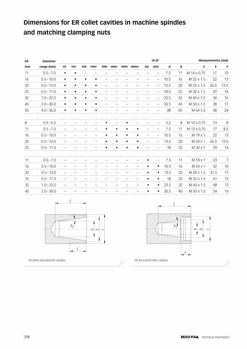
All other standard ER cavities ER AX and ER AXC cavities
Dimensions for ER collet cavities in machine spindles
and matching clamping nuts
ER Diameter Hi-Q® ������������!
size ������! ER ERC ERB ERBC ERM ERMC ERMX ERMXC AX AXC A B C E F
11 0.5 – 7.0 • • – – – – – – – – 7.5 11 M 14 x 0.75 17 10
16 0.5 – 10.0 • • • • – – – – – – 10.5 16 M 22 x 1.5 22 13
20 0.5 – 13.0 • • • • – – – – – – 13.5 20 M 25 x 1.5 26.5 13.5
25 0.5 – 17.0 • • • • – – – – – – 18.0 25 M 32 x 1.5 29 14
32 1.0 – 22.0 • • • • – – – – – – 23.5 32 M 40 x 1.5 34 16
40 2.0 – 30.0 • • • • – – – – – – 30.5 40 M 50 x 1.5 38 17
50 4.0 – 36.0 • • • • – – – – – – 38 50 M 64 x 2 48 24
8 0.5 – 5.0 – – – – • – • – – – 5.2 8 M 10 x 0.75 13 8
11 0.5 – 7.0 – – – – • • • • – – 7.5 11 M 13 x 0.75 17 8.5
16 0.5 – 10.0 – – – – • • • • – – 10.5 16 M 19 x 1 22 13
20 0.5 – 13.0 – – – – • • • • – – 13.5 20 M 24 x 1 26.5 13.5
25 0.5 – 17.0 – – – – • • • • – – 18 25 M 30 x 1 29 14
11 0.5 – 7.0 – – – – – – – – • – 7.5 11 M 18 x 1 23 7
16 0.5 – 10.0 – – – – – – – – • • 10.5 16 M 24 x 1 32 10
20 0.5 – 13.0 – – – – – – – – • • 13.5 20 M 28 x 1.5 37.5 11
25 0.5 – 17.0 – – – – – – – – • • 18 25 M 32 x 1.5 41 12
32 1.0 – 22.0 – – – – – – – – • • 23.5 32 M 40 x 1.5 48 12
40 2.0 – 30.0 – – – – – – – – • • 30.5 40 M 50 x 1.5 54 16
298 Technical information
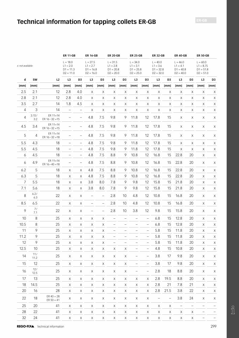
ER-GBTechnical information for tapping collets ER-GB
ER 11-GB ER 16-GB ER 20-GB ER 25-GB ER 32-GB ER 40-GB ER 50-GB
L = 18.0L1 = 2.0D1 = 11.3D2 = 11.0
L = 27.5L1 = 2.7D1 = 16.8D2 = 16.0
L = 31.5L1 = 2.8D1 = 20.8D2 = 20.0
L = 34.0L1 = 3.1D1 = 25.8D2 = 25.0
L = 40.0L1 = 3.6D1 = 32.8D2 = 32.0
L = 46.0L1 = 4.1D1 = 40.8D2 = 40.0
L = 60.0L1 = 8.75D1 = 51.8D2 = 51.0
d �� L2 L3 D3 L3 D3 L3 D3 L3 D3 L3 D3 L3 D3 L3 D3
�! �! �! �! �! �! �! �! �! �! �! �! �! �! �! �! �!
2.5 2.1 12 2.8 4.0 x x x x x x x x x x x x
2.8 2.1 12 2.8 4.0 x x x x x x x x x x x x
3.5 2.7 14 1.8 4.5 x x x x x x x x x x x x
4 3 14 – – x x x x x x x x x x x x
4 3.15 /3.2
ER 11=14 ER 16 – 32 =15 – – 4.8 7.5 9.8 9 11.8 12 17.8 15 x x x x
4.5 3.4 ER 11=14 ER 16 – 32 =15 – – 4.8 7.5 9.8 9 11.8 12 17.8 15 x x x x
5 4 ER 11=14 ER 16 – 32 =18 – – 4.8 7.5 9.8 9 11.8 12 17.8 15 x x x x
5.5 4.3 18 – – 4.8 7.5 9.8 9 11.8 12 17.8 15 x x x x
5.5 4.5 18 – – 4.8 7.5 9.8 9 11.8 12 17.8 15 x x x x
6 4.5 18 – – 4.8 7.5 8.8 9 10.8 12 16.8 15 22.8 20 x x
6 4.9 ER 11=14 ER 16 – 40 =18 – – 4.8 7.5 8.8 9 10.8 12 16.8 15 22.8 20 x x
6.2 5 18 x x 4.8 7.5 8.8 9 10.8 12 16.8 15 22.8 20 x x
6.3 5 18 x x 4.8 7.5 8.8 9 10.8 12 16.8 15 22.8 20 x x
7 5.5 18 x x 3.8 8.0 7.8 9 9.8 12 15.8 15 21.8 20 x x
7.1 5.6 18 x x 3.8 8.0 7.8 9 9.8 12 15.8 15 21.8 20 x x
8 6.2 /6.3 22 x x – – 2.8 10 4.8 12 10.8 15 16.8 20 x x
8.5 6.5 22 x x – – 2.8 10 4.8 12 10.8 15 16.8 20 x x
9 7 / 7.1 22 x x – – 2.8 10 3.8 12 9.8 15 15.8 20 x x
10 8 25 x x x x – – – – 6.8 15 12.8 20 x x
10.5 8 25 x x x x – – – – 6.8 15 12.8 20 x x
11 9 25 x x x x – – – – 5.8 15 11.8 20 x x
11.2 9 25 x x x x – – – – 5.8 15 11.8 20 x x
12 9 25 x x x x – – – – 5.8 15 11.8 20 x x
12.5 10 25 x x x x x x – – 4.8 15 10.8 20 x x
14 11 / 11.2 25 x x x x x x – – 3.8 17 9.8 20 x x
15 12 25 x x x x x x – – 3.8 17 9.8 20 x x
16 12 /12.5 25 x x x x x x – – 2.8 18 8.8 20 x x
17 13 25 x x x x x x x x 2.8 19.5 8.8 20 x x
18 14.5 25 x x x x x x x x 2.8 21 7.8 21 x x
20 16 28 x x x x x x x x 2.8 21.5 3.8 22 x x
22 18 ER 40 = 28 ER 50 = 41 x x x x x x x x – – 3.8 24 x x
25 20 41 x x x x x x x x x x – – – –
28 22 41 x x x x x x x x x x x x – –
32 24 41 x x x x x x x x x x x x – –
�.����� ( �� '��
299 Technical information

PCM ET1 ER MB
�� �!
�$
�)
��.�
+
#�
#$
�$+-)+17
!�2
'2
�
�$ �!
#! #�
�)
��
#)
'2
#$
�� #�#$ #! �(
�
��
�! �$
'2
!�2
PCM ET1 ER-MBER-GB, page 150
������������!
Type d D1 D2 L L1 L2 L3 L4
PCM ET1-12 3.55 7 11.5 18 16.5 2.5 5 5.5
PCM ET1-16 6.3 11 17 22 20 2.8 7 7
PCM ET1-20 7.1 14 21 24 23 2.8 8 7
PCM ET1-25 10 19 26 26 24 3 10 8
PCM ET1-32 12.5 23 33 33 32 3 1 10
PCM ET1-40 17 28 41 42 42 3 12 13
������������!
Type d D1 D2 D3 D4 L L1 L2 L3 L4
ER 8-MB 0.2 – 0.9 8.5 8 6.5 4 13.5 1.2 1.2 1.5 6
ER 11-MB 0.2 – 0.9 11.5 11 9.5 5 18 2 2 2.5 9
ER 16-MB 0.2 – 0.9 17 16 13.8 7.5 27.5 6.3 2.7 4 13
Technical information for tapping collets PCM ET1
Technical information for microbore collets
Expert advice
Do not use for coolant through tools and for applications with sealing disks.
Expert advice
ER-MB collets have no clamping range. Only nominal diameters h7 can be clamped.
300 Technical information

�!��
#�
�$
� #$
�!��
#�
�$
� #$
Reduction sleeves HS
������������!
Type d d D1 D2 L1 L2 L3
HS 12 HS 12-CF
Ø 3.0 3 – 12 16 40 29 4
Ø 1/8" 3.175 1/8 12 16 40 29 4
Ø 4.0 4 – 12 16 40 29 4
Ø 3/16" 4.763 3/16 12 16 40 29 4
Ø 5.0 5 – 12 16 40 29 4
Ø 6.0 6 – 12 16 40 36 4
Ø 1/4" 6.35 1/4 12 16 40 36 4
Ø 7.0 7 – 12 16 40 37 4
Ø 5/16" 7.938 5/16 12 16 40 37 4
Ø 8.0 8 – 12 16 40 37 4
Ø 9.0 9 – 12 16 40 37 4
Ø 3/8" 9.525 3/8 12 16 40 40 4
Ø 10.0 10 – 12 16 40 40 4
HS 12-MB
Ø 1.0 1 – 12 16 40 20 4
Ø 1.5 1.5 – 12 16 40 20 4
Ø 2.0 2 – 12 16 40 20 4
Ø 2.5 2.5 – 12 16 40 20 4
HS 20 HS 20-CF
Ø 3.0 3 – 20 25 50 28 4
Ø 1/8" 3.175 1/8 20 25 50 28 4
Ø 4.0 4 – 20 25 50 28 4
Ø 3/16" 4.763 3/16 20 25 50 28 4
Ø 5.0 5 – 20 25 50 28 4
Ø 6.0 6 – 20 25 50 36 4
Ø 1/4" 6.35 1/4 20 25 50 36 4
Ø 7.0 7 – 20 25 50 38 4
Ø 5/16" 7.938 5/16 20 25 50 37 4
Ø 8.0 8 – 20 25 50 37 4
Ø 9.0 9 – 20 25 50 38 4
Ø 3/8" 9.525 3/8 20 25 50 36 4
Ø 10.0 10 – 20 25 50 40 4
Ø 11.0 11 – 20 25 50 40 4
Ø 12.0 12 – 20 25 50 45 4
Ø 1/2" 12.7 1/2 20 25 50 45 4
Ø 13.0 13 – 20 25 50 45 4
Ø 14.0 14 – 20 25 50 45 4
Ø 15.0 15 – 20 25 50 45 4
Ø 5/8" 15.875 5/8 20 25 50 48 4
Ø 16.0 16 – 20 25 50 48 4
HS / HS-CF
HS 12-MB
301 Technical information

�!��
#�
�$
� #$
Reduction sleeves HS
������������!
Type d d D1 D2 L1 L2 L3
HS 25
Ø 3.0 3 – 25 30 56 29 4
Ø 1/8" 3.175 1/8 25 30 56 29 4
Ø 4.0 4 – 25 30 56 29 4
Ø 3/16" 4.763 3/16 25 30 56 29 4
Ø 5.0 5 – 25 30 56 29 4
Ø 6.0 6 – 25 30 56 37 4
Ø 1/4" 6.35 1/4 25 30 56 37 4
Ø 7.0 7 – 25 30 56 37 4
Ø 5/16" 7.938 5/16 25 30 56 37 4
Ø 8.0 8 – 25 30 56 37 4
Ø 9.0 9 – 25 30 56 38 4
Ø 3/8" 9.525 3/8 25 30 56 38 4
Ø 10.0 10 – 25 30 56 40 4
Ø 7/16" 11.112 7/16 25 30 56 40 4
Ø 12.0 12 – 25 30 56 46 4
Ø 1/2" 12.7 1/2 25 30 56 46 4
Ø 14.0 14 – 25 30 56 47 4
Ø 9/16" 14.288 9/16 25 30 56 47 4
Ø 5/8" 15.875 5/8 25 30 56 48 4
Ø 16.0 16 – 25 30 56 48 4
Ø 11/16" 17.461 11/16 25 30 56 48 4
Ø 18.0 18 – 25 30 56 48 4
Ø 3/4" 19.05 3/4 25 30 56 48 4
Ø 20.0 20 – 25 30 56 50 4
Ø 13/16" 20.638 13/16 25 30 56 50 4
HS
Expert advice
Reduction sleeve may be damaged, if clamped without a tool.
302 Technical information

�!��
#�
�$
� #$
Reduction sleeves HS
������������!
Type d d D1 D2 L1 L2 L3
HS 32 HS 32-CF
Ø 3/16" 4.763 3/16 32 36 60 29 4
Ø 5.0 5 – 32 36 60 29 4
Ø 6.0 6 – 32 36 60 36 4
Ø 1/4" 6.35 1/4 32 36 60 36 4
Ø 7.0 7 – 32 36 60 37 4
Ø 5/16" 7.938 5/16 32 36 60 36 4
Ø 8.0 8 – 32 36 60 36 4
Ø 9.0 9 – 32 36 60 37 4
Ø 3/8" 9.525 3/8 32 36 60 37 4
Ø 10.0 10 – 32 36 60 40 4
Ø 11.0 11 – 32 36 60 40 4
Ø 7/16" 11.112 7/16 32 36 60 45 4
Ø 12.0 12 – 32 36 60 45 4
Ø 1/2" 12.7 1/2 32 36 60 45 4
Ø 13.0 13 – 32 36 60 45 4
Ø 14.0 14 – 32 36 60 46 4
Ø 9/16" 14.288 9/16 32 36 60 46 4
Ø 15.0 15 – 32 36 60 46 4
Ø 5/8" 15.875 5/8 32 36 60 46 4
Ø 16.0 16 – 32 36 60 48 4
Ø 17.0 17 – 32 36 60 48 4
Ø 11/16" 17.461 11/16 32 36 60 48 4
Ø 18.0 18 – 32 36 60 49 4
Ø 19.0 19 – 32 36 60 49 4
Ø 3/4" 19.05 3/4 32 36 60 50 4
Ø 20.0 20 – 32 36 60 50 4
Ø 13/16" 20.638 13/16 32 36 60 50 4
Ø 22.0 22 – 32 36 60 50 4
Ø 7/8" 22.225 7/8 32 36 60 50 4
Ø 15/16" 23.813 15/16 32 36 60 52 4
Ø 25.0 25 – 32 36 60 56 4
Ø 1" 25.4 1 32 36 60 56 4
HS / HS-CF
303 Technical information

�!
#$
�$ ��
#�
��
#�
�$
�!
#$
�$ ��
#�
HSK SK BT CAPTO
DIN 69893 DIN 69871 MAS 403 ISO 26623
������������!
Type D1 D2 L1 L2 L3 G
HSK DIN 69893
HSK-A 25 25 19 10 13 2.5 –
HSK-C 25 25 19 8 13 2.5 –
HSK-E 25 25 19 10 13 2.5 –
HSK-A 32 32 24 20 16 3.2 –
HSK-C 32 32 24 10 16 3.2 –
HSK-E 32 32 24 20 16 3.2 –
HSK-A 40 40 30 20 20 4 –
HSK-C 40 40 30 10 20 4 –
HSK-E 40 40 30 20 20 4 –
HSK-A 50 50 38 26 25 5 –
HSK-C 50 50 38 12.5 25 5 –
HSK-E 50 50 38 26 25 5 –
HSK-F 50 50 30 26 20 4 –
HSK-A 63 63 48 26 32 6.3 –
HSK-C 63 63 48 12.5 32 6.3 –
HSK-E 63 63 48 26 32 6.3 –
HSK-F 63 63 38 26 25 5 –
HSK-A 80 80 60 26 40 8 –
HSK-C 80 80 60 16 40 8 –
HSK-F 80 80 48 26 32 6.3 –
HSK-A 100 100 75 29 50 10 –
HSK-C 100 100 75 16 50 10 –
HSK-E 100 100 70 29 50 10 –
SK DIN 69871
SK 30 31.75 50 3.2 47.8 15.85 M 12
SK 40 44.45 63.55 3.2 68.4 15.85 M 16
SK 50 69.85 97.5 3.2 101.75 15.85 M 24
BT MAS 403
BT 30 31.75 46 2 48.4 20 M 12
BT 40 44.45 63 2 65.4 25 M 16
BT 50 69.85 100 3 101.8 35 M 24
Polygon shank CAPTO ISO 26623
Polygon shank C3 32 – 15 19 – M 12 x 1.5
Polygon shank C4 40 – 20 24 – M 14 x 1.5
Polygon shank C5 50 – 20 30 – M 16 x 1.5
Polygon shank C6 63 – 22 38 – M 20 x 2
Polygon shank C8 80 – 30 48 – M 20 x 2
Spindle interface norms
SK
BT
CAPTO
��
#�
�$
�!
#$
HSK-A / HSK-C
���$
�!
#$ #�
HSK-E / HSK-F
304 Technical information

HSK forms and their key characteristics HSK
DIN 69893
ISO 12164
C ����
/ / Standard type for machining centers and milling machines/ / For automatic tool change/ / Coolant supply through center via coolant tube/ / Drive keys at the end of HSK taper/ / ������ ���@������������$���}��U�V���������������
is available on request)?������ '�����������*� ����� ������,����������������� �� �������� ���
Form B
/ / For machining centers, milling and turning machines/ / *�����������@������������ ������������@��������@���/ / For automatic tool change/ / ��������������������������������/ / �����"����������������
?( �� '��������5����
Form C
/ / For transfer lines, special machines and modular tooling systems
/ / For manual tool change/ / Drive keys at the end of HSK taper
Form D
/ / For special machines/ / *�����������@������������ ������������@��������@���/ / For manual tool change/ / ���������������������������������/ / �����"����������������
?( �� '��������5����
Form E
/ / For high-speed applications/ / For automatic tool change/ / Coolant supply through center via coolant tube/ / Without any drive keys for absolute symmetry
Form F
/ / For high-speed applications/ / *�����������@������������ ������������@��������@���/ / For automatic tool change/ / Without any drive keys for absolute symmetry
305 Technical information

HSK
DIN 69893
ISO 12164
HSK interface
Positioning grooves
Balancing holes /$�' � ����������� ����� ���� � "� ������'���0
Orientation notch
Access holes for manual clamping
Face contact
Taper
Driving slots for torque transmission
Balancing holes / ������' � ����������� ����3 ���!"#$%�� ����0
Position with clamped HSK toolholder
Clamping set in clamped position
Position with unclamped HSK toolholder
Data-carrier bore forBalluff chip assembly
Coolant tube
Clamping set in unclamped position
306 Technical information

BalancingThe experience of REGO-FIX in the development and manufacturing of tool holding systems has provided us a large knowledge basis on the subject of balancing.
In our production we have the latest manufacturing equip-ment and testing methods available, but as with other manufacturers the physical limits of balancing have to be considered. Furthermore, it has to be considered whether a process is economically feasible and the imbalance measurable. The weights and interaction of the individual components of the tool holding system determines which options for balancing are practical. Therefore, we recommend that the entire assembly be considered as a whole, as it is stipulated in the DIN 69888.
�������������(� Imbalance occurs when the mass of a rotating body is not distributed rotationally symmetric. This leads to vibration and can cause increased wear or damage to cutting tools and or machine bearing components. The weight of each part of the tool holding system is critical to the question: At what speed is balancing economically ���@���^��������@������������������������������������� �-gal forces. Due to its nature the centrifugal force increase exponentially, which means when you double the speed you get four times the centrifugal force.
Static imbalance A static unbalance results when the axis of rotation does not pass through the center of gravity axis of the rotary body. The axis of rotation is parallel to the axis of gravity, but is displaced by some amount. This displacement (called eccentricity) produces a rotational circular vibration perpendicular to the rotational axis. This imbalance can be measured in a stationary position.
axis of gravity
axis of rotation
To reduce a static imbalance an appropriate weight is removed or adjusted perpendicular to the rotational axis.
axis of gravity
axis of rotation
weight added
308 Technical information
axis of gravity
axis of rotation
weight removed
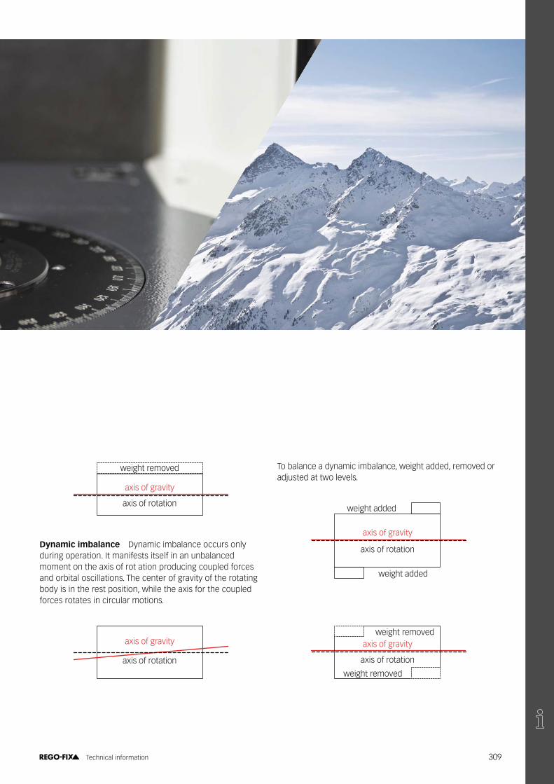
Dynamic imbalance Dynamic imbalance occurs only during operation. It manifests itself in an unbalanced moment on the axis of rot ation producing coupled forces and orbital oscillations. The center of gravity of the rotating body is in the rest position, while the axis for the coupled forces rotates in circular motions.
axis of gravity
axis of rotation
To balance a dynamic imbalance, weight added, removed or adjusted at two levels.
axis of gravity
axis of rotation
weight added
weight added
axis of gravity
axis of rotation
weight removed
weight removed
309 Technical information

Machine spindle The spindle rotors are supported in the spindle housing in several locations and have for the most part a weight of about 15 kg. Therefore, they can be balanced much more accurately than a small rotating body such as a toolholder of only 200 g.
ToolholderThe toolholder is the largest component in the interface between the spindle and the tool. These are balanced accord-ing to the manufacturer at the factory.
ColletThese are usually rotationally symmetrical parts and do not have to be balanced. Installation error (eg. not correct clamping) or pollution (chips, dried coolant etc.) can cause an imbalance.
Clamping nutThese are balanced according to manufacturer. Dirt, debris or damage can cause an imbalance.
Accessories for clamping systemAccessories, such as coolant tubes, stop screws, pull studs, sealing and cooling disks may cause an additional imbalance.
ToolCutting tool design may (eg, single-edged, Weldon clamping surface, etc.) already have an imbalance.
\ ��� ������ ��~�"�������The tool change position accuracy of toolholders can play a large role in the balancing and repeatability of the measured imbalance. An HSK holder has a position repeatability of be-tween 2-4 microns while most steep taper holders can be up to 5 microns. Impurities on the cone or on the mating surfacebetween the toolholder and the spindle can also lead to an imbalance and larger position inaccuracies. So as can been it is very important to clean all surfaces thoroughly as to mini-mize the position error that can occur.
#Y��(��� ����������(�The whole toolholding system and spindle should be considered as well as ������������������������������@���@#���������������@���������������������@�on the spindle. The weight of the individual components and the speeds are important factors to consider as well.
310 Technical information

Formulas
G = e × w =U
×Y��������
=��������� U = Unbalance of the rotor
G = Balance quality(gmm)(mm/s)
M 60 M × 30
result U =G × M × 30
M = Weight of the rotor n = Speed of the rotors
(g) (1/min) �����
Conversion factor = 9.549 e = Eccentricity of gravityw = Angular speed
(μm)(1/sec)
Uzul =
G × M× 9.549Uzul = Permitted residual unbalance of the rotorezul = Permitted eccentricity
(gmm)(μm)n
ezul =
Uzul
u = Unbalance mass on the largest outer radius (g)M
u =
Uzul
R = Radius at which the balancing is done (mm)R
Balancing qualityIn recent years the cutting speeds have increased because of better materials and processes. This has resulted in new requirements on the balance of the whole system (machine spindle, clamping tool and tool).
General informations can be read in the Norm DIN ISO 19499:2008-03 “Mechanical vibration – Balancing – Guidance on the use and application of balancing standards“.
Norms
Selection of DIN ISO 1940}��������@��@������������������������������^������������regulated grades of rotors in a constant (rigid) state. This standard is not applicable for tooling systems for the follow-ing reasons entire.
Spindles, tool holder systems and cutting tools have, in con-trast to other rigid rotors (such as electric motor armatures, etc.) essential differences:a) Spindle, tool holder and cutting tool form a system with
high temporal variation (for example, frequent tool change machining centers).
b) Due to the radial angle and tension-related inaccuracies a repeated change of tool in the spindle leads to a change in the balancing state of the entire system.
c) Fit tolerances of individual components (spindle, tool hold-er and cutting tool) set limits for balancing.
Selection of DIN 69888:2008-09}��������@��@����������^���������������������� �����������systems with HSK 25 to HSK 100 according DIN 69063-1, DIN 69063-2, DIN 69063-5, DIN 69063-6, DIN 69893-1, DIN 69893-2, $���U�U�#����@�$���U�U�#��������^���@���������������������operating speed. In this standard the HSK 125 and HSK 160 are not given any consideration, so it is recommended to ap-ply the limits for HSK 100. Correspondingly, the standard tool for systems with interfaces and tapers such as ABS, CAPTO, � Z������@������@����������"��������@������Z���������#��������aspects of the interfaces and holders are taken into account.
The standard applies under the following conditions:a) In the area of operating speeds the tool systems are
considered to be rigid.^�� �}���������� ���^����������������������������@����@�^������
permissible bearing load of the machine spindle.c) So as not to unbalance-related impairments in the produc-
����������������������������'�������������@������������@�in the standard requirements (load bearing and thus the vibration velocity).
Importance of balance of qualityBy balancing quality value G, the weight of the rotor (M), the speed (n) and the conversion factor (9549), the permissible residual unbalance Uzul is calculated in gmm. It tells us how much mass asymmetrically distributed in the radial direction from the axis of rotation is still permissible. With the calcu-lated value, the distance of this mass may be recalculated to gravitational axis.
311 Technical information

ComparisonThe comparison between the overall system and a single toolholder demonstrates that the balance of the individual component has a very small effect on the overall system.
Overall system
Machine spindle for HSK-A 63
15,000 g
Toolholder HSK-A 63
ER32X080-H1035 g
Collet ER 32-UP
6.00 – 5.00150 g
Seal diskDS / ER 326.00 – 5.50
15 g
Clamping nutHi-Q ERC 32
15 g
Cutter withinternal cooling
ø 6 mm30 g
Uzul10 000 =2.5 x 16,398 x 9.549
= 39.146 gmm Uzul42 000 =2.5 x 16,398 x 9.549
= 9.321 gmm10,000 42,000
ezul10 000 =39.146
= 2.387 μm ezul42 000 =9.321
= 0.568 μm16,398 16,398
u10 000 =39.146
= 1.2 g u42 000 =9.321
= 0.3 g31.5 31.5
By calculation the entire system is allowed 1.2 g at 10,000 min-1 and 0.3 g at 42,000 min-1 and the permissible unbalanced mass is at its greatest diameter (in this case the spindle rotor). The following calculation is used to demonstrate how little unbalanced mass of a toolholder HSK-A 63 / ER32 x 080 is acceptable in comparison to the overall system:
Uzul10 000= 2.5 x 1035 x 9.549 = 2.471 gmm Uzul42 000
= 2.5 x 1035 x 9.549 = 0.588 gmm10,000 42,000
ezul10 000 =2.471
= 2.380 μm ezul42 000 =0.588
= ��������1035 1035
u10 000= 2.471 = 0.078 g u42 000
= 0.588 = 0.019 g31.5 31.5
If now the allowable imbalance masses are compared, it is evident that in the overall system may be about 15 times larger than in the toolholder alone. The current state of balancing technology is not economically producible when just looking at the toolholder, but when the entire system is considered it may not necessary. An imbalance caused by positioning error can’t be corrected or accounted for.
Weight 16398 g
Radius (R) 31.5 mm
Speed 10,000 min-1 42,000 min-1
Balance quality (G) 2.5 2.5
Permitted residual unbalance (Uzul) 39.146 gmm 9.321 gmm
Permitted eccentricity (ezul) Y���V��� ��������
Weight 1035 g
Radius (R) 31.5 mm
Speed 10,000 min-1 42,000 min-1
Balance quality (G) 2.5 2.5
Permitted residual unbalance (Uzul) 2.471 gmm 0.588 gmm
Permitted eccentricity (ezul) Y���V��� ��������
312 Technical information

Balancing at REGO-FIXAll toolholders and clamping nuts from the production of REGO-FIX are �̂ ������@�������� �������^��@�������$���@@�����Z������������@������������ balanced and 100% customized. The balancing data refer only to the tool-holder. Most REGO-FIX toolholders are designed to accommodate the REGO-FIX Hi-Q®�^��������������� �������^���������'�����������@�
)�����@������������,� �� ��� ������ �����(�������������' @�������� ���'��������,����������� ����3�,���� �� ������������ ������������������������� ��
�������� ��������������A���� ���� � ������� �������
Stop feature of the locking screw*
Locking screw
elastomer ring
Fine balance with Hi-Q® balancing ringsREGO-FIX Hi-Q® balancing rings (patented) are mounted on the grooves designed into the toolholder, making all the clamping system (holder, nut, tool, etc.) balanceable.
313 Technical information

Details of the balance values of toolholdersThe stated REGO-FIX balance values (noted in packaging, catalogs, brochures, etc.) are the actual measured values from the state-of-the-art-balancers.
ToolholderThese toolholders are under production on a Level (static) as standard balanced at:
G 2.5 @ 25,000 min-1 SK 40 BT 40 CAT 40 SK 50 BT 50 CAT 50 CAT 50+ CAT 40+ BT 50+ BT 40+ HSK 100 HSK 125 HSK 80 HSK 63 Capto (C3, C4, C5, C6, C8)
balanced to 30,000 min-1 BT 30 SK 30 CAT 30 BT 30+ BT-OM 30
balanced to 33,000 min-1 HSK 80 F HSK 80 FP
balanced to 36,000 min-1 HSK 50
balanced to 45,000 min-1 HSK 40
balanced to 50,000 min-1 ISO 20 (HAAS) HSK 32-25 / PG 6 x 046
balanced to 60,000 min-1 HSK 32
balanced to 90,000 min-1 HSK 20 / HSK 25
G 2.5 @ 5,000 min-1 all XL toolholders
HSK – ToolholderThese toolholders are balanced by a special process (Pat. pend.), in which two axially spaced staggered levels material ablated.
Level 2 (machine-side removal of material) (Pat. pend.)
Level 1 (tool-side removal of material)
*Other balance qualities are available on request at an additional cost. It can’t be guaranteed that these values are reproduc-�^���@��������������������������@������������������������������������������;�������@�}�����>��� ��������@������Z�������J��
Hi-Q® – Clamping nutThe REGO-FIX-Hi-Q® clamping nuts are balanced due to its design (patented) and are continuously tested during production.
ColletsCollets are rotationally symmetric and do not require balancing. To enable the best possible concentricity collets must be cleaned before each use.
Accessories (sealing disks, coolant disks, etc.)These are rotationally symmetric and do not require balancing. To enable the best possible concentricity the accessories must be cleaned before each use. By improper handling or installation can lead to imbalance.
314 Technical information

Interpreting the DIN 69888:2008-09
The accuracy of balancing machines is only partially dependent on the tool mass, i.e. for small tool masses (< 1,5kg), the inaccuracy of balancing machines is much more noticeable.
$���@@�������������������� �����^�����������������Z����������������������������� ���������� ����^��'�����������@�����@� the balancing machine. The following assumptions can be made:
Repeatable residual imbalances per balancing plane
max. mass of test piece (rotor) kg repeatable residual unbalancea Uwm gmm
< 7.0 0.75
> 7.0 to 16.0 1.5a Depending on the clamping accuracy in the machine. The clamping accuracy of the balancing machine is greater thanthat of the machine.
In addition to the repeated residual imbalances on a balancing machine (Uwm), further error lies in the limited repeatability of ����� ������|���� �������������� ����������������������� ����Z�������������������@����������^�������^��������@�
Joining accuracy of the HSK interface
HSK 25 32 40 50 63 80 100eHSK 2 2 2 2 2 3 4
$�������������
Thus, the repeated achievable residual unbalance of the overall system can be calculated:
U����¤��m'"��¥�eHSK) + Uwm
Example 1Toolholder type: HSK-E 40 / PG 10 x 062 Mass of toolholder: mwkz = 0.250 kg Joining accuracy HSK interface: eHSK = 2 μm for HSK 40 Reproducible residual unbalance: Uwm = 0.75 gmm for mass < 7.0 kg
�����¤����Y��"��§�Y�����¨���V������{�J�Y������
Example 2Toolholder type: HSK-A 63 / PG 32 x 100 Mass of toolholder: mwkz = 1.228 kg Joining accuracy HSK interface: eHSK = 2 μm for HSK 63 Reproducible residual unbalance: Uwm = 0.75 gmm for mass < 7.0 kg
u����¤��J�YY��"��§�Y�����¨���V������{���Y������
Compared to the permissible residual unbalance, which results at G 2.5 @ 25 000 min-1, the values calculated above for the reproducible residual unbalance are partially higher. As a result, not all G values are reproducible.
315 Technical information
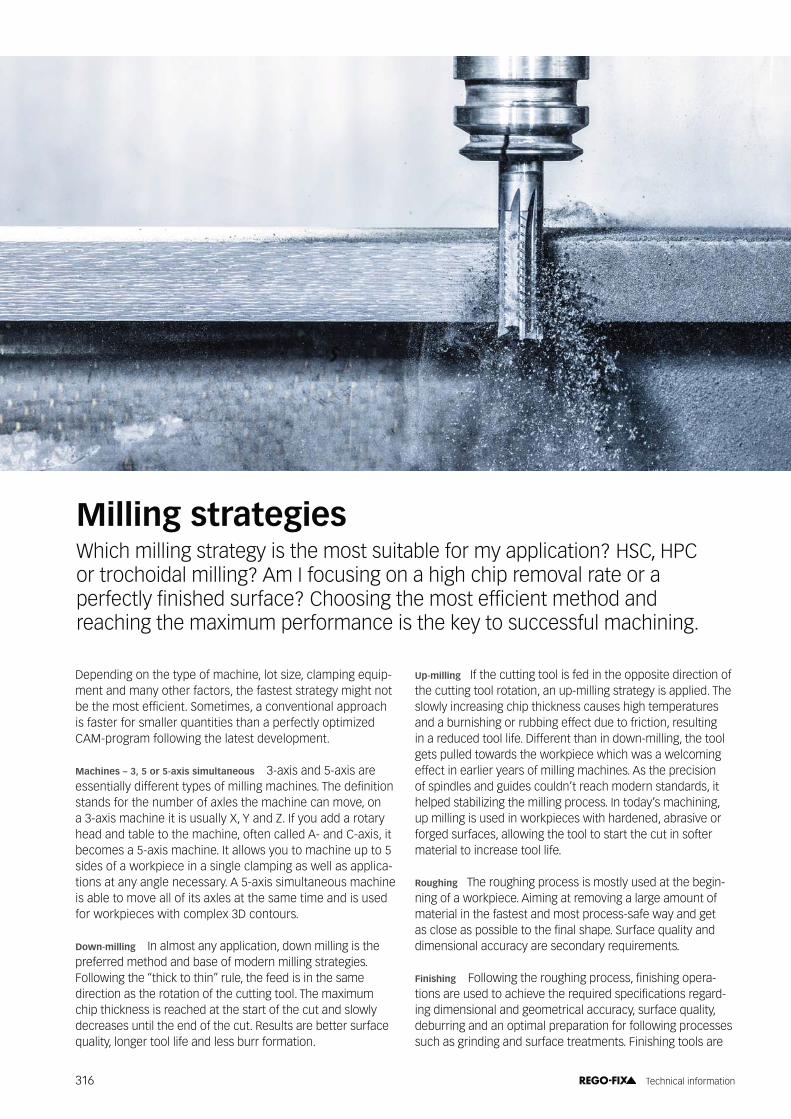
Milling strategiesWhich milling strategy is the most suitable for my application? HSC, HPC or trochoidal milling? Am I focusing on a high chip removal rate or a ���� ������������@���� ������������������������ ������������@���@� reaching the maximum performance is the key to successful machining.
Depending on the type of machine, lot size, clamping equip-ment and many other factors, the fastest strategy might not ^������������ �����������������Z�������������������������is faster for smaller quantities than a perfectly optimized CAM-program following the latest development.
Machines – 3, 5 or 5-axis simultaneous 3-axis and 5-axis are ������������@� ������������� �������������������}���@���������stands for the number of axles the machine can move, on a 3-axis machine it is usually X, Y and Z. If you add a rotary head and table to the machine, often called A- and C-axis, it becomes a 5-axis machine. It allows you to machine up to 5 sides of a workpiece in a single clamping as well as applica-tions at any angle necessary. A 5-axis simultaneous machine is able to move all of its axles at the same time and is used for workpieces with complex 3D contours.
Down-milling In almost any application, down milling is the preferred method and base of modern milling strategies. Following the “thick to thin” rule, the feed is in the same direction as the rotation of the cutting tool. The maximum chip thickness is reached at the start of the cut and slowly decreases until the end of the cut. Results are better surface quality, longer tool life and less burr formation.
Up-milling If the cutting tool is fed in the opposite direction of the cutting tool rotation, an up-milling strategy is applied. The slowly increasing chip thickness causes high temperatures and a burnishing or rubbing effect due to friction, resulting in a reduced tool life. Different than in down-milling, the tool gets pulled towards the workpiece which was a welcoming effect in earlier years of milling machines. As the precision of spindles and guides couldn’t reach modern standards, it helped stabilizing the milling process. In today’s machining, up milling is used in workpieces with hardened, abrasive or forged surfaces, allowing the tool to start the cut in softer material to increase tool life.
Roughing The roughing process is mostly used at the begin-ning of a workpiece. Aiming at removing a large amount of material in the fastest and most process-safe way and get �����������������^������������������������� ��������������@�dimensional accuracy are secondary requirements.
Finishing >����'������������������������Z���������������-�������������@�����������������������@��������������������@-ing dimensional and geometrical accuracy, surface quality, deburring and an optimal preparation for following processes such as grinding and surface treatments. Finishing tools are
316 Technical information

@������@������������� ���������������Z�����'�������������������speeds and developed to reach a long tool life for a stable process.
HSC HSC, short for High Speed Cutting, essentially increases the metal removal rate Q by practicing exceedingly higher speeds and feeds up to 10 times and very low cutting depth and width. Compared to conventional milling methods, HSC results in an up to 30 % higher material removal rate while at the same time achieving better surface quality, lower cutting forces and less heat development due to short contact times. Applications can be found in thin-walled structural parts for the aerospace industry, turbine blades, moulds or electrodes. While HSC is generating lower forces on the spindle, the tool-ing machine has the requirement to be able to withstand high rpm and fast movements on long term.
HPC High Performance Cutting also has its target in reaching the highest possible metal removal rate Q, although using a different strategy. While the cutting speed Vc will not reach the levels of HSC, the increased cutting depth and cutting width will make the difference. While the rotational speeds and the feeds are suitable for almost any type of machines, strong forces will appear to the spindle. As the surface quality mostly is lower than in High Speed Cutting, HPC is mainly used in the roughing process. Also, it has fewer requirements to CAM and programming-systems.
Trochoidal Milling Similar to HSC, trochoidal milling is based on high speeds and feeds, small Ae and maximal Ap. Mainly used in roughing and semi-roughing, its application is found in slots, corners and deep pockets. Due to a constant circu-���#��"��������������������������'����������������������������affects the spindle and guides. The small chip thickness ����'�������'�����������@����������������������������������Z�resulting and a stronger core and increased stability to pre-vent vibrations.
Tool in cutting process
Entrance into and exit from cut
Rapid feed
Relative feed direction
317 Technical information
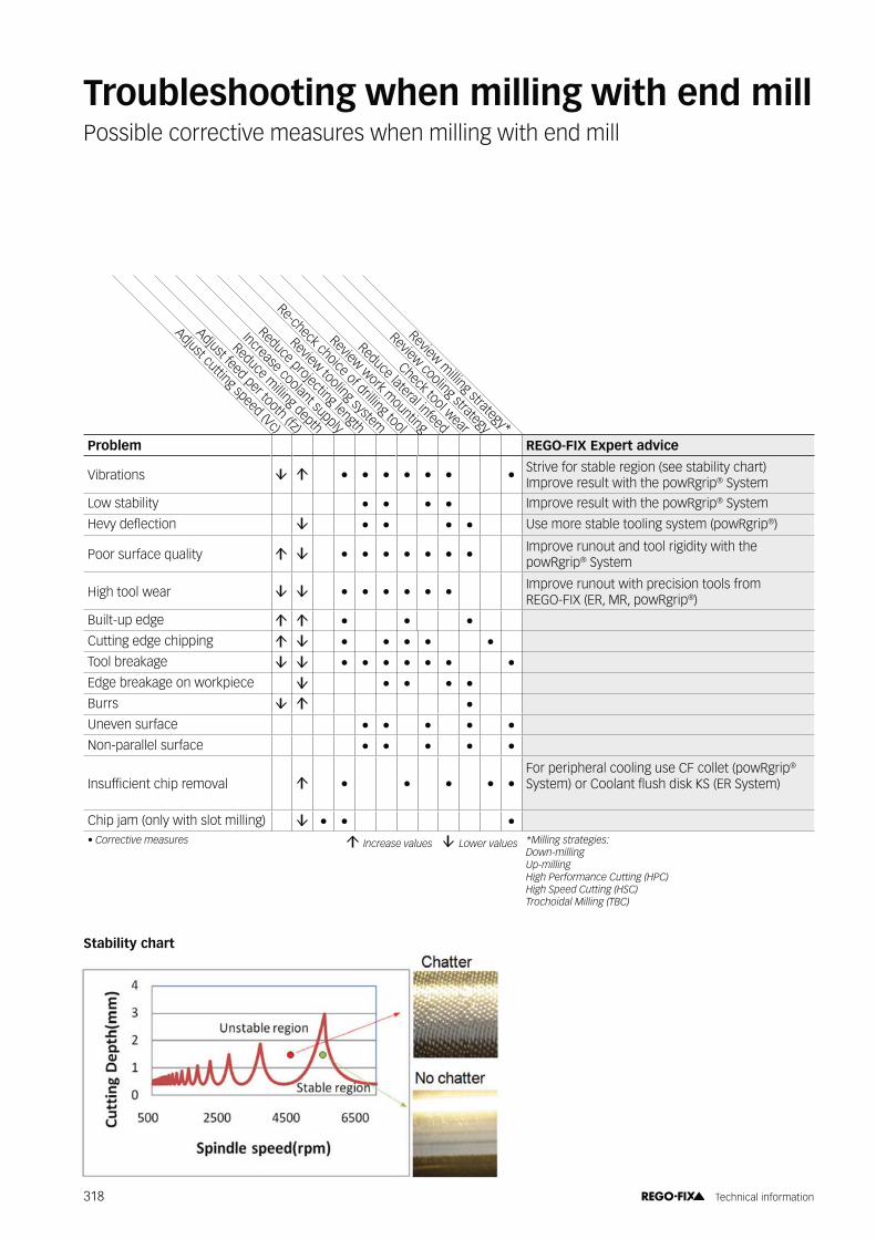
Adjust cutting speed (Vc)
Adjust feed per tooth (fz)
Review tooling system
Review work mounting
Reduce milling depth
Reduce lateral infeed
Increase coolant supply
Check tool wear
Reduce projecting length
Re-check choice of drilling tool
Review cooling strategy
Review milling strategy*
Problem REGO-FIX Expert advice
Vibrations • • • • • • • Strive for stable region (see stability chart) Improve result with the powRgrip® System
Low stability • • • • Improve result with the powRgrip® System
�����@�������� • • • • Use more stable tooling system (powRgrip®)
Poor surface quality • • • • • • • Improve runout and tool rigidity with the powRgrip® System
High tool wear • • • • • • Improve runout with precision tools from REGO-FIX (ER, MR, powRgrip®)
Built-up edge • • •Cutting edge chipping • • • • •Tool breakage • • • • • • •Edge breakage on workpiece • • • •Burrs •Uneven surface • • • • •Non-parallel surface • • • • •
$��� ������������������� • • • • •For peripheral cooling use CF collet ( powRgrip®
������������������������@��"�����;���������
Chip jam (only with slot milling) • • •B�*�������(���� ������ � $���� ���( ����� � ��,���( ���� )C���������� ������.
��,�"������� 7�"������� :���+������ ����*�������/:+*0 :���D�����*�������/:D*0 ������ ��C�������/1*0
Troubleshooting when milling with end millPossible corrective measures when milling with end mill
Stability chart
318 Technical information
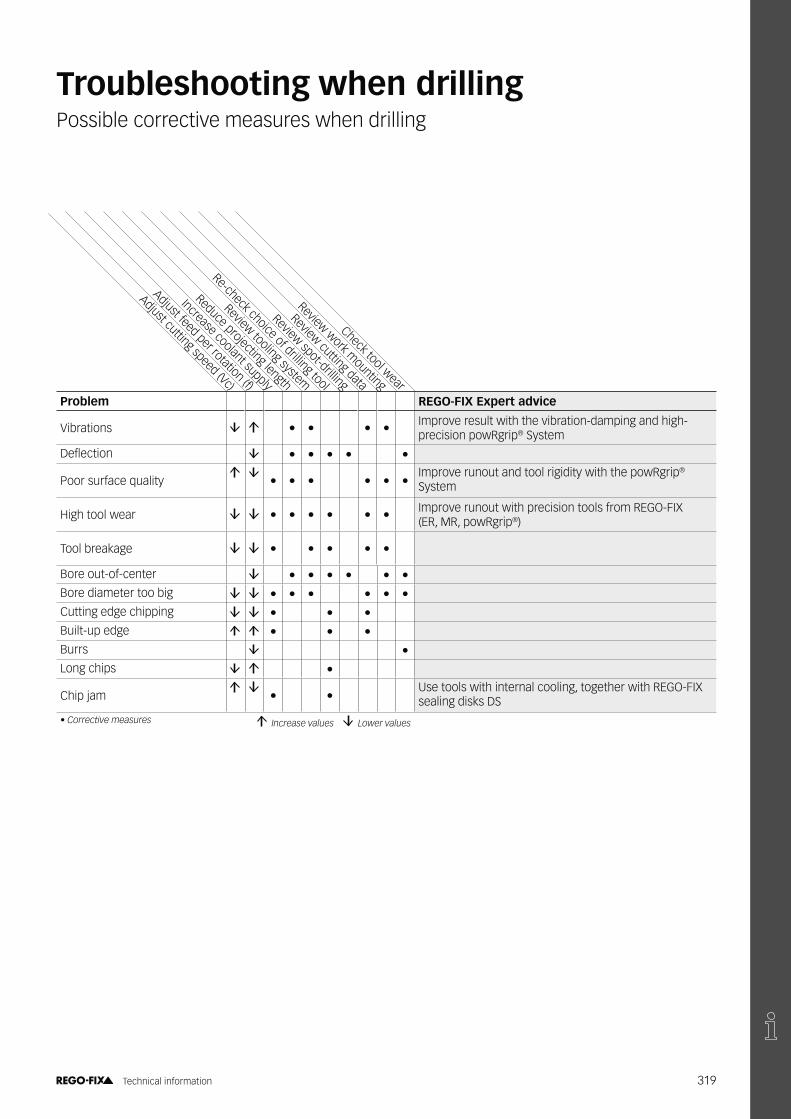
Adjust cutting speed (Vc)
Adjust feed per rotation (f)
Re-check choice of drilling tool
Review cutting data
Increase coolant supply
Review work mounting
Reduce projecting length
Check tool wear
Review tooling system
Review spot-drilling
Problem REGO-FIX Expert advice
Vibrations • • • • Improve result with the vibration-damping and high- precision powRgrip® System
�������� • • • • •
Poor surface quality • • • • • •Improve runout and tool rigidity with the powRgrip®
System
High tool wear • • • • • • Improve runout with precision tools from REGO-FIX (ER, MR, powRgrip®)
Tool breakage • • • • •
Bore out-of-center • • • • • •Bore diameter too big • • • • • •Cutting edge chipping • • •Built-up edge • • •Burrs •Long chips •
Chip jam • •Use tools with internal cooling, together with REGO-FIX sealing disks DS
B�*�������(���� ������ � $���� ���( ����� � ��,���( ����
Troubleshooting when drillingPossible corrective measures when drilling
319 Technical information

Adjust cutting speed (Vc)
Adjust feed per rotation (f)
Review cutting data
Extend pilot bore depth
Adjust pilot bore diameter
Check axial offset
Reduce projecting length
Increase coolant supply
Check tool wearProblem REGO-FIX Expert advice
Vibrations • • •
Poor surface quality • • • • • Improve result with the self-centering REGO-FIX ������������"
Built-up edge •Cutting edge chipping • • • •
Tool breakage • • • • Improve result with the self-centering REGO-FIX ������������"
High tool wear • • •
Bore not cylindrical • • Improve result with the self-centering REGO-FIX ������������"
Bore too small • • • Eliminate radial forces with the self-centering REGO-FIX ������������"
Bore too big • • • Eliminate radial forces with the self-centering REGO-FIX ������������"
Chip jam • • •B�*�������(���� ����� � $���� ���( ����� � ��,���( ����
Troubleshooting when reamingPossible corrective measures when reaming
320 Technical information
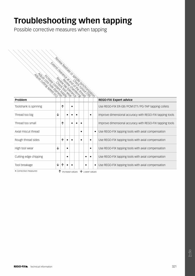
Adjust cutting speed (Vc)
Adjust core hole diameter
Review chamfering
Check runout (TIR)
Increase coolant supply
Review feedrate or spindle synchronization
Check tool wear
Review tap tolerance
Extend clearance at end of the thread Problem REGO-FIX Expert advice
Toolshank is spinning • Use REGO-FIX ER-GB / PCM ET1 / PG-TAP tapping collets
Thread too big • • • • Improve dimensional accuracy with REGO-FIX tapping tools
Thread too small • • • Improve dimensional accuracy with REGO-FIX tapping tools
Axial miscut thread • • Use REGO-FIX tapping tools with axial compensation
Rough thread sides • • • • Use REGO-FIX tapping tools with axial compensation
High tool wear • • Use REGO-FIX tapping tools with axial compensation
Cutting edge chipping • • • Use REGO-FIX tapping tools with axial compensation
Tool breakage • • • • Use REGO-FIX tapping tools with axial compensation
B�*�������(���� ������ � $���� ���( ����� � ��,���( ����
Troubleshooting when tappingPossible corrective measures when tapping
321 Technical information

Formulas for cutting data
End millsd1 Diameter of the cutting edge [mm]z Number of cutting edgesap Axial infeed depth [mm]ae Radial infeed depth [mm]vc Cutting speed [m / min]fz Feed per tooth and revolution [mm]n Spindle speed [min-1]vf Feed rate [mm / min]f Feed per rotation [mm]Q Material removal rate [cm3/min]deff Effective engagement diameter [mm]ß Setting angle «Beta» [° – DEG]
Drillsd1 Diameter of the cutting edge [mm]vc Cutting speed [m / min]f Feed per rotation [mm]n Spindle speed [min-1]vf Feed rate [m / min]Q Material removal rate [cm3/min]T Primary processing time for the maximum drill depth of
the tool [sec]L Effective drill depth [mm]
Tapsa Dimension of square endd Nominal diameter of the threadn Spindle speedP Thread pitchvc Cutting speedvf Feed rate
Spindle speed n =VC × 1000
@���¬1
min
Cutting speed Vc =d1�������¬
1000m
min
Feed rate Vf = fz × z × nmmmin
Feed per tooth fz =Vf
z × nmm
Feed per revolution f = fz × z mm
Material removal rate Q =ap × ae × Vf
1000cm3
min
Spindle speed n =VC × 1000
d1���¬1
min
Cutting speed Vc =d1�������¬
1000m
min
Feed rate Vf = f × nmmmin
Material removal rate Q =d1
2���¬���f
4 × 1000cm3
min
Primary processing time T =LVf
× 60 sec
Spindle speed n =VC × 1000
@���¬1
min
Cutting speed Vc =@���¬����
1000m
min
Feed rate Vf = P × nmmmin
322 Technical information

Cutting speed conversion table for threading
Vc m / min
���1
1min-1
2 3 4 5 6 8 10 12 15 20 25 30 40 50 60
1 318 637 955 1273 1592 1910 2546 3183 3820 4775 6366 7958 9549 12732 15915 19099
2 159 318 477 637 796 955 1273 1592 1910 2387 3183 3979 4775 6366 7958 9549
3 106 212 318 424 531 637 849 1051 1273 1592 2122 2653 3183 2144 5305 6366
4 80 159 239 318 398 477 637 796 955 1194 1592 1989 2387 3163 3979 4775
5 64 127 191 255 318 382 509 637 764 955 1273 1592 1910 2546 3183 3820
6 53 106 159 212 265 318 424 531 637 796 1061 1326 1592 2122 26553 3183
8 40 80 119 159 199 239 318 398 477 597 796 995 1194 1592 1989 2387
10 32 64 95 127 159 191 255 318 382 477 637 796 955 1273 1592 1910
12 27 53 80 106 133 159 212 265 318 398 531 663 796 1061 1326 1592
14 23 45 68 91 114 136 183 227 273 341 455 568 682 909 1137 1364
16 20 40 60 80 99 119 159 199 239 298 398 497 597 796 995 1194
18 18 35 53 71 86 106 141 177 212 265 354 442 531 707 884 1061
20 16 32 48 64 80 95 127 159 191 239 318 398 477 637 796 955
25 13 25 38 51 64 76 102 127 153 191 255 318 382 509 637 764
30 11 21 32 42 53 64 85 106 127 159 212 265 318 424 531 637
35 9 18 27 36 45 55 73 91 109 136 182 227 273 364 455 546
40 8 16 24 32 40 48 64 80 95 119 159 199 239 318 398 477
45 7 14 21 28 35 42 57 71 85 106 141 177 212 283 354 424
50 6 13 19 25 32 38 51 64 76 95 127 159 191 255 318 382
323 Technical information
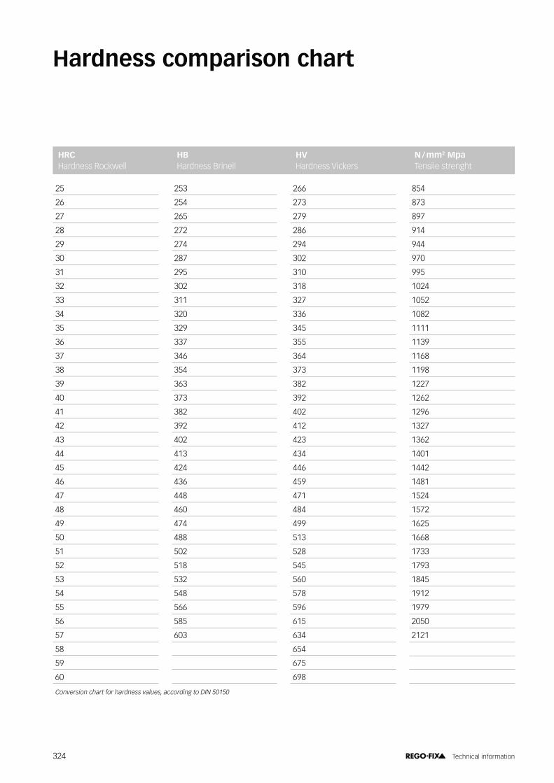
Hardness comparison chart
HRC Hardness Rockwell
HB Hardness Brinell
HV Hardness Vickers
N / mm2 Mpa Tensile strenght
25 253 266 854
26 254 273 873
27 265 279 897
28 272 286 914
29 274 294 944
30 287 302 970
31 295 310 995
32 302 318 1024
33 311 327 1052
34 320 336 1082
35 329 345 1111
36 337 355 1139
37 346 364 1168
38 354 373 1198
39 363 382 1227
40 373 392 1262
41 382 402 1296
42 392 412 1327
43 402 423 1362
44 413 434 1401
45 424 446 1442
46 436 459 1481
47 448 471 1524
48 460 484 1572
49 474 499 1625
50 488 513 1668
51 502 528 1733
52 518 545 1793
53 532 560 1845
54 548 578 1912
55 566 596 1979
56 585 615 2050
57 603 634 2121
58 654
59 675
60 698
*��(�������� ������� �������( ����3� �������������$&�=E>=E
324 Technical information

Conversion table / inch-metric
0“d1
Ømm
0“d1
Ømm
0“d1
Ømm
0“d1
Ømm
0“d1
Ømm
0“d1
Ømm
0
1/16
3/32
1/8
5/32
3/16
7/32
1/4
5/16
3/8
7/16
1/2
0
1.5875
2.3812
3.1750
3.9687
4.7625
5.5562
6.3500
7.9375
9.5250
11.1125
12.7000
2-1/16
2-1/8
2-3/16
2-1/4
2-5/16
2-3/8
2-7/16
2-1/2
–
–
–
–
52.3876
53.9751
55.5626
57.1501
58.7376
60.3251
61.9126
63.5001
–
–
–
–
4-1/16
4-1/8
4-3/16
4-1/4
4-5/16
4-3/8
4-7/16
4-1/2
–
–
–
–
103.188
104.775
106.363
107.950
109.538
111.125
112.713
114.300
–
–
–
–
6-1/16
6-1/8
6-3/16
6-1/4
6-5/16
6-3/8
6-7/16
6-1/2
–
–
–
–
153.988
155.575
157.163
158.750
160.338
161.925
163.513
165.100
–
–
–
–
8-1/16
8-1/8
8-3/16
8-1/4
8-5/16
8-3/8
8-7/16
8-1/2
–
–
–
–
204.788
206.375
207.963
209.550
211.138
212.725
214.313
215.900
–
–
–
–
10-1/16
10-1/8
10-3/16
10-1/4
10-5/16
10-3/8
10-7/16
10-1/2
–
–
–
–
255.588
257.176
258.763
260.351
261.938
263.526
265.113
266.701
–
–
–
–
9/16
5/8
11/16
3/4
13/16
7/8
15/16
1
14.2875
15.8750
17.4625
19.0500
20.6375
22.2250
23.8125
25.4001
2-9/16
2-5/8
2-11/16
2-3/4
2-13/16
2-7/8
2-15/16
3
65.0876
66.6751
68.2626
69.8501
71.4376
73.0251
74.6126
76.2002
4-9/16
4-5/8
4-11/16
4-3/4
4-13/16
4-7/8
4-15/16
5
115.888
117.475
119.063
120.650
122.238
123.825
125.413
127.00
6-9/16
6-5/8
6-11/16
6-3/4
6-13/16
6-7/8
6-15/16
7
166.688
168.275
169.863
171.450
173.038
174.625
176.213
177.800
8-9/16
8-5/8
8-11/16
8-3/4
8-13/16
8-7/8
8-15/16
9
217.488
219.075
220.663
222.250
223.838
225.425
227.013
228.600
10-9/16
10-5/8
10-11/16
10-3/4
10-13/16
10-7/8
10-15/16
11
268.288
269.876
271.463
273.051
274.638
276.226
277.813
279.401
1-1/16
1-1/8
1-3/16
1-1/4
1-5/16
1-3/8
1-7/16
1-1/2
26.9876
28.5751
30.1626
31.7501
33.3376
34.9251
36.5126
38.1001
3-1/16
3-1/8
3-3/16
3-1/4
3-5/16
3-3/8
3-7/16
3-1/2
77.7877
79.3752
80.9627
82.5502
84.1377
85.7252
87.3127
88.9002
5-1/16
5-1/8
5-3/16
5-1/4
5-5/16
5-3/8
5-7/16
5-1/2
128.588
130.175
131.763
133.350
134.938
136.525
138.113
139.700
7-1/16
7-1/8
7-3/16
7-1/4
7-5/16
7-3/8
7-7/16
7-1/2
179.388
180.975
182.563
184.150
184.738
187.325
188.913
190.500
9-1/16
9-1/8
9-3/16
9-1/4
9-5/16
9-3/8
9-7/16
9-1/2
230.188
231.775
233.363
234.950
236.538
238.125
239.713
241.300
11-1/16
11-1/8
11-3/16
11-1/4
11-5/16
11-3/8
11-7/16
11-1/2
280.988
282.576
284.163
285.751
287.338
288.926
290.513
292.101
1-9/16
1-5/8
1-11/16
1-3/4
1-13/16
1-7/8
1-15/16
2
39.6876
41.2751
42.8626
44.4501
46.0376
47.6251
49.2126
50.8001
3-9/16
3-5/8
3-11/16
3-3/4
3-13/16
3-7/8
3-15/16
4
90.4877
92.0752
93.6627
95.2502
96.8377
98.4252
100.013
101 .600
5-9/16
5-5/8
5-11/16
5-3/4
5-13/16
5-7/8
5-15/16
6
141.288
142.875
144.463
146.051
147.638
149.225
150.813
152.400
7-9/16
7-5/8
7-11/16
7-3/4
7-13/16
7-7/8
7-15/16
8
192.088
193.675
195.263
196.850
198.438
200.025
201 .613
203.200
9-9/16
9-5/8
9-11/16
9-3/4
9-13/16
9-7/8
9-15/16
10
242.888
244.475
246.063
247.650
249.238
250.825
252.413
254.001
11-9/16
11-5/8
11-11/16
11-3/4
11-13/16
11-7/8
11-15/16
12
293.688
295.276
296.863
298.451
300.038
301.626
303.213
304.801
325 Technical information

Form and position tolerances in practiceForm tolerances according to DIN EN ISO 1101
t
t
t
t
���
���
���
���
©�F�&!+$2�$������� ��C������������� �����':
Straightness The tolerance zone is limited by two parallel lines at a distance t apart. Every envelope line of the toleranced cylinder must be between these two parallel lines.
Example Every envelope line of the toler-anced cylinder surface must be between two parallel lines at a distance apart of 0.1.
Example The circumference line of the toleranced cylinder must be within a circle ring of the zone width 0.1 in every radial section plane.
Example The real workpiece area must be between two parallel planes at a distance apart of 0.2.
Example The toleranced cylindrical area must be between two coaxial cylinders with a radial distance of 0.1.
Roundness The tolerance zone is limited by two concentric circles at a distance t apart. The circumference line of the toleranced cylinder must be within a circle ring of the zone width t, in every radial section plane.
Flatness The tolerance zone is limited by two parallel planes at a distance t apart, the dimensions of which correspond to those of the toleranced area. The real workpiece area must be between the two parallel planes at distance t apart.
Cylindricity The tolerance zone for the cylin-der envelope area limits the deviation of the roundness, the straightness of the envelope line and the parallelism of the envelope line to the cylinder axis. It is formed by two coaxial cylinders with the radial distance t.
326 Technical information

Position tolerances according to DIN EN ISO 1101
t
��� A
A
#
��� A
A
��� A
A
20°
��� A
A
t
20°
t
t
©�F�&!+$2�$������� ��C������������� �����':
Parallelism The tolerance zone within which the envelope lines of the toleranced cylinder must lie is limited by two parallel lines at a distance t apart which run parallel to the datum plane.
Example Every single envelope line of the toleranced area must be between two parallel lines that are at a distance of 0.1 apart, and are parallel to the center axis.
Example All points / circle lines of the toler-anced area must be between two parallel planes that are at a distance of 0.1 apart, and are perpendicular to the datum plane.
Example All points of the toleranced area must be between two parallel planes that are at a distance apart of 0.1, and are angled at 20 º to the datum axis.
Example The axis of the toleranced cylinder must be within a cylinder that has a diameter of 0.1 and is coaxial to the datum axis A.
Perpendicularity The tolerance zone is limited by two parallel planes at a distance t apart, which are perpendicular to the datum axis. The toleranced plane face must be between these two planes.
Angularity The tolerance zone is limited by two parallel planes at a distance t apart at the nominal angle to the datum axis.
Coaxiality The tolerance zone is limited by a cylinder of diameter t, the axis of which matches the datum axis. The actual axis of the toleranced element must be within the tolerance zone.
327 Technical information
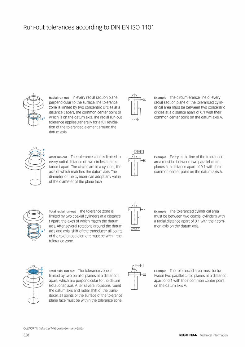
Run-out tolerances according to DIN EN ISO 1101
t��� A
A
��� A
A
�
���� A
A
��� A
A
t
t
t
Radial run-out In every radial section plane perpendicular to the surface, the tolerance zone is limited by two concentric circles at a distance t apart, the common center point of which is on the datum axis. The radial run-out tolerance applies generally for a full revolu-tion of the toleranced element around the datum axis.
Example The circumference line of every radial section plane of the toleranced cylin-drical area must be between two concentric circles at a distance apart of 0.1 with their common center point on the datum axis A.
Axial run-out The tolerance zone is limited in every radial distance of two circles at a dis-tance t apart. The circles are in a cylinder, the axis of which matches the datum axis. The diameter of the cylinder can adopt any value of the diameter of the plane face.
Example Every circle line of the toleranced area must be between two parallel circle planes at a distance apart of 0.1 with their common center point on the datum axis A.
Total radial run-out The tolerance zone is limited by two coaxial cylinders at a distance t apart, the axes of which match the datum axis. After several rotations around the datum axis and axial shift of the transducer all points of the toleranced element must be within the tolerance zone.
Example The toleranced cylindrical area must be between two coaxial cylinders with a radial distance apart of 0.1 with their com-mon axis on the datum axis.
Total axial run-out The tolerance zone is limited by two parallel planes at a distance t apart, which are perpendicular to the datum (rotational) axis. After several rotations round the datum axis and radial shift of the trans-ducer, all points of the surface of the tolerance plane face must be within the tolerance zone.
Example The toleranced area must be be-tween two parallel circle planes at a distance apart of 0.1 with their common center point on the datum axis A.
©�F�&!+$2�$������� ��C������������� �����':
328 Technical information


Tolerance charts
Outside dimensions (Shafts)Tolerances on dimensions in μm
Nominal size range in mm
g4 g5 g6 g7 h4 h5 h6 h7 h8 h9 h10 h11 h13
from 1 to 3
-2 -5
-2 -6
-2 -8
-2 -12
0 -3
0 -4
0 -6
0 -10
0 -14
0 -25
0 -40
0 -60
0 -140
over 3 to 6
-4 -8
-4 -9
-4 -12
-4 -16
0 -4
0 -5
0 -8
0 -12
0 -18
0 -30
0 -48
0 -75
0 -180
over 6 to 10
-5 -9
-5 -11
-5 -14
-5 -20
0 -4
0 -6
0 -9
0 -15
0 -22
0 -36
0 -58
0 -90
0 -220
over 10 to 18
-6 -11
-6 -14
-6 -17
-6 -24
0 -5
0 -8
0 -11
0 -18
0 -27
0 -43
0 -70
0 -110
0 -270
over 18 to 30
-7 -13
-7 -16
-7 -20
-7 -28
0 -6
0 -9
0 -13
0 -21
0 -33
0 -52
0 -84
0 -130
0 -330
over 30 to 50
-9 -16
-9 -25
-9 -20
-9 -34
0 -7
0 -11
0 -16
0 -25
0 -39
0 -62
0 -100
0 -160
0 -390
Nominal size range in mm
G4 G5 G6 G7 H4 H5 H6 H7 H8 H9 H10 H11 H13
from 1 to 3
+5 +2
+6 +2
+8 +2
+12 +2
+3 0
+4 0
+6 0
+10 0
+14 0
+25 0
+40 0
+60 0
+140 0
over 3 to 6
+8 +4
+9 +4
+12 +4
+16 +4
+4 0
+5 0
+8 0
+12 0
+18 0
+30 0
+48 0
+75 0
+180 0
over 6 to 10
+9 +5
+11 +5
+14 +5
+20 +5
+4 0
+6 0
+9 0
+15 0
+22 0
+36 0
+58 0
+90 0
+220 0
over 10 to 18
+11 +6
+14 +6
+17 +6
+24 +6
+5 0
+8 0
+11 0
+18 0
+27 0
+43 0
+70 0
+110 0
+270 0
over 18 to 30
+13 +7
+16 +7
+20 +7
+28 +7
+6 0
+9 0
+13 0
+21 0
+33 0
+52 0
+84 0
+130 0
+330 0
over 30 to 50
+16 +9
+25 +9
+20 +9
+34 +9
+7 0
+11 0
+16 0
+25 0
+39 0
+62 0
+100 0
+160 0
+390 0
Inside dimensions (Bores)Tolerances on dimensions in μm
330 Technical information

Thread tolerances
331 Technical information

Core hole diameters for thread cutting���#��J���#�_�*�J���}��~���
d1 mm ���� ���%� �����������*1 0.25 0.729 0.785 0.75
*1.1 0.25 0.829 0.885 0.85*1.2 0.25 0.929 0.985 0.95*1.4 0.30 1.075 1.142 1.101.6 0.35 1.221 1.321 1.251.7 0.35 1.321 1.421 1.351.8 0.35 1.421 1.521 1.45
2 0.40 1.567 1.679 1.602.2 0.45 1.713 1.838 1.752.3 0.40 1.867 1.979 1.902.5 0.45 2.013 2.138 2.052.6 0.45 2.113 2.238 2.15
3 0.50 2.459 2.599 2.503.5 0.60 2.850 3.010 2.90
4 0.70 3.242 3.422 3.304.5 0.75 3.688 3.878 3.75
5 0.80 4.134 4.334 4.206 1.00 4.917 5.153 5.007 1.00 5.917 6.153 6.008 1.25 6.647 6.912 6.809 1.25 7.647 7.912 7.80
10 1.50 8.376 8.676 8.5011 1.50 9.376 9.676 9.5012 1.75 10.106 10.441 10.2014 2.00 11.835 12.210 12.0016 2.00 13.835 14.210 14.0018 2.50 15.294 15.744 15.5020 2.50 17.294 17.744 17.5022 2.50 19.294 19.744 19.5024 3.00 20.752 21.252 21.0027 3.00 23.752 24.252 24.0030 3.50 26.211 26.771 26.5033 3.50 29.211 29.771 29.5036 4.00 31.670 32.270 32.0039 4.00 34.670 35.270 35.0042 4.50 37.129 37.799 37.5045 4.50 40.129 40.799 40.5048 5.00 42.587 43.297 43.0052 5.00 46.587 47.297 47.0056 5.50 50.046 50.796 50.50
MF DIN 13, ISO 261, 6Hd1 mm ���� ���%� �����������
2.5 0.35 2.121 2.221 2.15
3 0.35 2.621 2.721 2.65
3.5 0.35 3.121 3.221 3.15
4 0.50 3.459 3.599 3.50
MF DIN 13, ISO 261, 6Hd1 mm ���� ���%� ��guide line
4.5 0.50 3.959 4.099 4.00
5 0.50 4.459 4.599 4.50
5.5 0.50 4.959 5.099 5.00
6 0.75 5.188 5.378 5.25
7 0.75 6.188 6.378 6.25
8 0.75 7.188 7.378 7.25
8 1.00 6.917 7.153 7.00
9 0.75 8.188 8.378 8.25
9 1.00 7.917 8.153 8.00
10 0.75 9.188 9.378 9.25
10 1.00 8.917 9.153 9.00
10 1.25 8.647 8.912 8.80
11 0.75 10.188 10.378 10.25
11 1.00 9.917 10.153 10.00
12 1.00 10.917 11.153 11.00
12 1.25 10.647 10.912 10.80
12 1.50 10.376 10.676 10.50
14 1.00 12.917 13.153 13.00
14 1.25 12.647 12.912 12.80
14 1.50 12.376 12.676 12.50
15 1.00 13.917 14.153 14.00
15 1.50 13.376 13.676 13.50
16 1.00 14.917 15.153 15.00
16 1.50 14.376 14.676 14.50
17 1.00 15.917 16.153 16.00
17 1.50 15.376 15.676 15.50
18 1.00 16.917 17.153 17.00
18 1.50 16.376 16.676 16.50
18 2.00 15.835 16.210 16.00
20 1.00 18.917 19.153 19.00
20 1.50 18.376 18.676 18.50
20 2.00 17.835 18.210 18.00
22 1.00 20.917 21.153 21.00
22 1.50 20.376 20.676 20.50
22 2.00 19.835 20.210 20.00
24 1.00 22.917 23.153 23.00
24 1.50 22.376 22.676 22.50
24 2.00 21.835 22.210 22.00
25 1.00 23.917 24.153 24.00
25 1.50 23.376 23.676 23.50
25 2.00 22.835 23.210 23.00
27 1.50 25.376 25.676 25.50
27 2.00 24.835 25.210 25.00
28 1.00 26.917 27.153 27.00
28 1.50 26.376 26.676 26.50
28 2.00 25.835 26.210 26.00
30 1.00 28.917 29.153 29.00
332 Technical information

MF DIN 13, ISO 261, 6Hd1 mm ���� ���%� ��guide line
30 1.50 28.376 28.676 28.50
30 2.00 27.835 28.210 28.00
32 1.50 30.376 30.676 30.50
32 2.00 29.835 30.210 30.00
33 1.50 31.376 31.676 31.50
33 2.00 30.835 31.210 31.00
35 1.50 33.376 33.676 33.50
36 1.50 34.376 34.676 34.50
36 2.00 33.835 34.210 34.00
36 3.00 32.752 33.252 33.00
39 1.50 37.376 37.676 37.50
39 2.00 36.835 37.210 37.00
39 3.00 35.752 36.252 36.00
40 1.50 38.376 38.676 38.50
40 2.00 37.835 38.210 38.00
40 3.00 36.752 37.252 37.00
42 1.50 40.376 40.676 40.50
42 2.00 39.835 40.210 40.00
42 3.00 38.752 39.252 39.00
45 1.50 43.376 43.676 43.50
45 2.00 42.835 43.210 43.00
45 3.00 41.752 42.252 42.00
48 1.50 46.376 46.676 46.50
48 2.00 45.835 46.210 46.00
48 3.00 44.752 45.252 45.00
50 1.50 48.376 48.676 48.50
50 2.00 47.835 48.210 48.00
50 3.00 46.752 47.252 47.00
52 1.50 50.376 50.676 50.50
52 2.00 49.835 50.210 50.00
52 3.00 48.752 49.252 49.00
55 2.00 52.835 53.210 53.00
60 2.00 57.835 58.210 58.00
UNJC ISO 3161:1999, 3Bd1 TPI mm ���� ���%� �����������
4 40 0.635 2.228 2.393 2.30
5 40 0.635 2.558 2.723 2.60
6 32 0.794 2.733 2.939 2.80
8 32 0.794 3.393 3.599 3.45
10 24 1.058 3.795 4.064 3.90
12 24 1.058 4.455 4.704 4.55
1/4" 20 1.270 5.113 5.387 5.20
5/16" 18 1.411 6.563 6.833 6.70
3/8" 16 1.588 7.978 8.255 8.10
7/16" 14 1.814 9.347 9.639 9.40
1/2" 13 1.954 10.798 11.095 10.90
9/16" 12 2.117 12.228 12.482 12.40
5/8" 11 2.309 13.627 13.904 13.80
3/4" 10 2.540 16.576 16.881 16.70
UNC ANSI B1.1, 2Bd1 TPI mm ���� ���%� �����������
1 64 0.397 1.425 1.582 1.45
2 56 0.454 1.695 1.871 1.75
3 48 0.529 1.941 2.146 2.00
4 40 0.635 2.157 2.385 2.25
5 40 0.635 2.487 2.697 2.55
6 32 0.794 2.642 2.895 2.75
8 32 0.794 3.302 3.530 3.40
10 24 1.058 3.683 3.962 3.80
12 24 1.058 4.344 4.597 4.40
1/4" 20 1.270 4.979 5.257 5.10
5/16" 18 1.411 6.401 6.731 6.50
3/8" 16 1.588 7.798 8.153 8.00
7/16" 14 1.814 9.144 9.550 9.30
1/2" 13 1.954 10.592 11.023 10.80
9/16" 12 2.117 11.989 12.446 12.20
5/8" 11 2.309 13.386 13.868 13.60
3/4" 10 2.540 16.307 16.840 16.60
7/8" 9 2.822 19.177 19.761 19.50
1" 8 3.175 21.971 22.606 22.30
1 1/8" 7 3.629 24.638 25.349 25.00
1 1/4" 7 3.629 27.813 28.524 28.20
1 3/8" 6 4.233 30.353 31.115 30.80
1 1/2" 6 4.233 33.528 34.290 34.00
1 3/4" 5 5.080 38.964 39.827 39.50
2" 4.5 5.644 44.679 45.593 45.30
MF EN 60423:1994, 7Hd1 mm ���� ���%� �����������
8 1.00 6.917 7.217 7.00
10 1.00 8.917 9.217 9.00
12 1.50 10.376 10.751 10.50
16 1.50 14.376 14.751 14.50
20 1.50 18.376 18.751 18.50
25 1.50 23.376 23.751 23.50
32 1.50 30.376 30.751 30.50
40 1.50 38.376 38.751 38.50
63 1.50 61.376 61.751 61.50
333 Technical information

Core hole diameters for thread cutting
UNJF ISO 3161:1999, 3Bd1 TPI mm ���� ���%� �����������
0 80 0.318 1.217 1.298 1.25
1 72 0.353 1.511 1.603 1.55
2 64 0.397 1.798 1.902 1.85
3 56 0.454 2.073 2.189 2.15
4 48 0.529 2.329 2.466 2.35
5 44 0.577 2.614 2.764 2.70
6 40 0.635 2.888 3.053 2.95
8 36 0.706 3.480 3.663 3.60
10 32 0.794 4.054 4.255 4.10
12 28 0.907 4.602 4.816 4.70
1/4" 28 0.907 5.466 5.662 5.55
5/16" 24 1.058 6.906 7.109 7.00
3/8" 24 1.058 8.494 8.679 8.60
7/16" 20 1.270 9.876 10.084 10.00
1/2" 20 1.270 11.463 11.661 11.55
9/16" 18 1.411 12.913 13.122 13.05
5/8" 18 1.411 14.501 14.702 14.60
3/4" 16 1.588 17.506 17.722 17.60
7/8" 14 1.814 20.460 20.706 20.50
1" 12 2.117 23.340 23.594 23.40
UNF ANSI B1.1, 2Bd1 TPI mm ���� ���%� �����������
0 80 0.318 1.182 1.305 1.20
1 72 0.353 1.474 1.612 1.50
2 64 0.397 1.756 1.912 1.80
3 56 0.454 2.025 2.197 2.10
4 48 0.529 2.271 2.458 2.35
5 44 0.577 2.551 2.740 2.60
6 40 0.635 2.820 3.022 2.90
8 36 0.706 3.404 3.606 3.50
10 32 0.794 3.963 4.165 4.05
12 28 0.907 4.496 4.724 4.60
1/4" 28 0.907 5.360 5.588 5.50
5/16" 24 1.058 6.782 7.035 6.90
3/8" 24 1.058 8.382 8.636 8.50
7/16" 20 1.270 9.729 10.033 9.80
1/2" 20 1.270 11.329 11.607 11.40
9/16" 18 1.411 12.751 13.081 12.90
5/8" 18 1.411 14.351 14.681 14.50
3/4" 16 1.588 17.323 17.678 17.50
7/8" 14 1.814 20.270 20.675 20.40
1" 12 2.117 23.114 23.571 23.30
1 1/8" 12 2.117 26.289 26.746 26.50
1 1/4" 12 2.117 29.464 29.921 29.70
1 3/8" 12 2.117 32.639 33.096 32.80
1 1/2" 12 2.117 35.814 36.271 36.00
UNEF ANSI B1.1, 2Bd1 TPI mm ���� ���%� �����������
12 32 0.794 4.623 4.826 4.70
1/4" 32 0.794 5.487 5.689 5.60
5/16" 32 0.794 7.087 7.264 7.20
3/8" 32 0.794 8.662 8.864 8.75
7/16" 28 0.907 10.135 10.337 10.25
1/2" 28 0.907 11.710 11.938 11.85
9/16" 24 1.058 13.132 13.385 13.20
5/8" 24 1.058 14.732 14.986 14.80
11/16" 24 1.058 16.307 16.560 16.40
3/4" 20 1.270 17.679 17.957 17.80
13/16" 20 1.270 19.254 19.558 19.40
7/8" 20 1.270 20.854 21.132 21.00
1" 20 1.270 24.029 24.307 24.10
UN ANSI B1.1, 2Bd1 TPI mm ���� ���%� �����������
5/16" 20 1.270 6.554 6.858 6.70
3/8" 20 1.270 8.154 8.432 8.30
9/16" 20 1.270 12.904 13.208 13.00
5/8" 20 1.270 14.504 14.782 14.60
1 1/8" 8 3.175 25.146 25.781 25.50
1 1/4" 8 3.175 28.321 28.956 28.70
1 3/8" 8 3.175 31.496 32.131 31.80
1 1/2" 8 3.175 34.671 35.306 35.00
1 5/8" 8 3.175 37.846 38.481 38.20
1 3/4" 8 3.175 41.021 41.656 41.40
1 7/8" 8 3.175 44.196 44.831 44.50
2" 8 3.175 47.371 48.006 47.70
2 1/4" 8 3.175 53.721 54.356 54.10
2 1/2" 8 3.175 60.071 60.706 60.40
334 Technical information
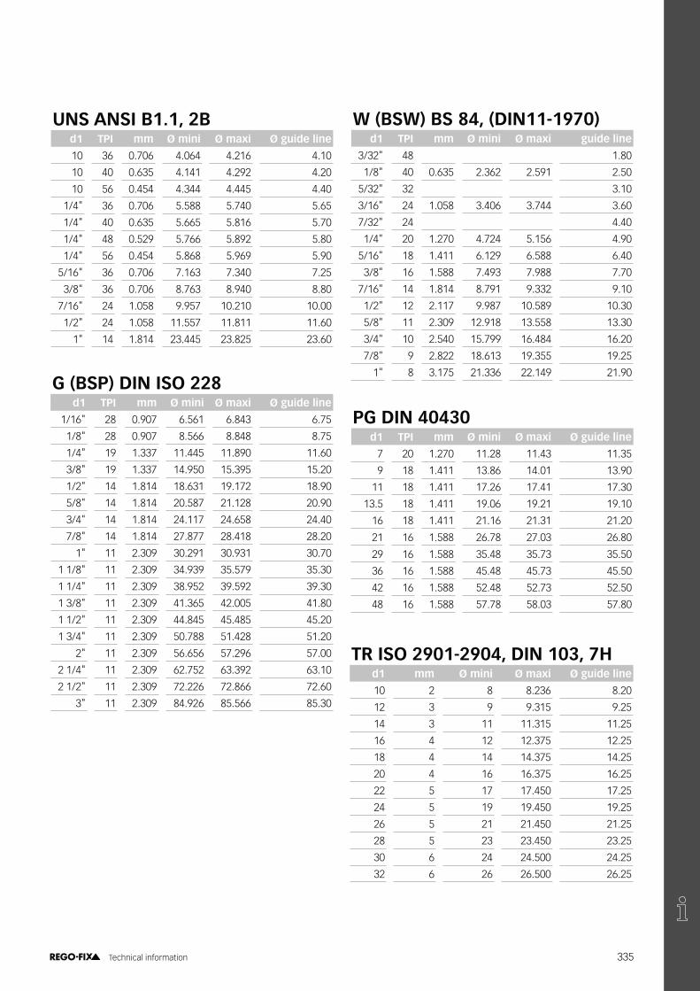
G (BSP) DIN ISO 228d1 TPI mm ���� ���%� �����������
1/16" 28 0.907 6.561 6.843 6.75
1/8" 28 0.907 8.566 8.848 8.75
1/4" 19 1.337 11.445 11.890 11.60
3/8" 19 1.337 14.950 15.395 15.20
1/2" 14 1.814 18.631 19.172 18.90
5/8" 14 1.814 20.587 21.128 20.90
3/4" 14 1.814 24.117 24.658 24.40
7/8" 14 1.814 27.877 28.418 28.20
1" 11 2.309 30.291 30.931 30.70
1 1/8" 11 2.309 34.939 35.579 35.30
1 1/4" 11 2.309 38.952 39.592 39.30
1 3/8" 11 2.309 41.365 42.005 41.80
1 1/2" 11 2.309 44.845 45.485 45.20
1 3/4" 11 2.309 50.788 51.428 51.20
2" 11 2.309 56.656 57.296 57.00
2 1/4" 11 2.309 62.752 63.392 63.10
2 1/2" 11 2.309 72.226 72.866 72.60
3" 11 2.309 84.926 85.566 85.30
UNS ANSI B1.1, 2Bd1 TPI mm ���� ���%� �����������
10 36 0.706 4.064 4.216 4.10
10 40 0.635 4.141 4.292 4.20
10 56 0.454 4.344 4.445 4.40
1/4" 36 0.706 5.588 5.740 5.65
1/4" 40 0.635 5.665 5.816 5.70
1/4" 48 0.529 5.766 5.892 5.80
1/4" 56 0.454 5.868 5.969 5.90
5/16" 36 0.706 7.163 7.340 7.25
3/8" 36 0.706 8.763 8.940 8.80
7/16" 24 1.058 9.957 10.210 10.00
1/2" 24 1.058 11.557 11.811 11.60
1" 14 1.814 23.445 23.825 23.60
���]����]��������#�JJ�J��+�d1 TPI mm ���� ���%� guide line
3/32" 48 1.80
1/8" 40 0.635 2.362 2.591 2.50
5/32" 32 3.10
3/16" 24 1.058 3.406 3.744 3.60
7/32" 24 4.40
1/4" 20 1.270 4.724 5.156 4.90
5/16" 18 1.411 6.129 6.588 6.40
3/8" 16 1.588 7.493 7.988 7.70
7/16" 14 1.814 8.791 9.332 9.10
1/2" 12 2.117 9.987 10.589 10.30
5/8" 11 2.309 12.918 13.558 13.30
3/4" 10 2.540 15.799 16.484 16.20
7/8" 9 2.822 18.613 19.355 19.25
1" 8 3.175 21.336 22.149 21.90
PG DIN 40430d1 TPI mm ���� ���%� �����������
7 20 1.270 11.28 11.43 11.35
9 18 1.411 13.86 14.01 13.90
11 18 1.411 17.26 17.41 17.30
13.5 18 1.411 19.06 19.21 19.10
16 18 1.411 21.16 21.31 21.20
21 16 1.588 26.78 27.03 26.80
29 16 1.588 35.48 35.73 35.50
36 16 1.588 45.48 45.73 45.50
42 16 1.588 52.48 52.73 52.50
48 16 1.588 57.78 58.03 57.80
TR ISO 2901-2904, DIN 103, 7Hd1 mm ���� ���%� �����������
10 2 8 8.236 8.20
12 3 9 9.315 9.25
14 3 11 11.315 11.25
16 4 12 12.375 12.25
18 4 14 14.375 14.25
20 4 16 16.375 16.25
22 5 17 17.450 17.25
24 5 19 19.450 19.25
26 5 21 21.450 21.25
28 5 23 23.450 23.25
30 6 24 24.500 24.25
32 6 26 26.500 26.25
335 Technical information
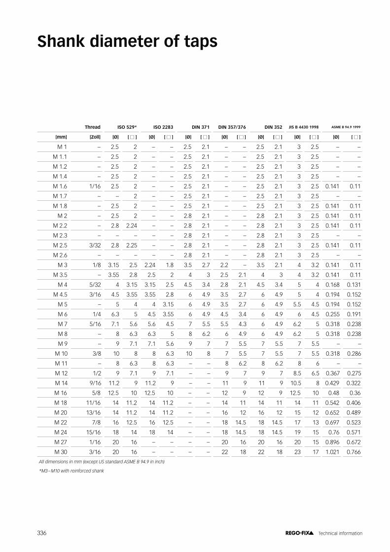
Thread #�_�}*�� ISO 2283 DIN 371 DIN 357/376 DIN 352 JIS B 4430 1998 ASME B 94.9 1999
�! �� ��! ��! � ! ��! � ! ��! � ! ��! � ! ��! � ! ��! � ! ��! � !
M 1 – 2.5 2 – – 2.5 2.1 – – 2.5 2.1 3 2.5 – –
M 1.1 – 2.5 2 – – 2.5 2.1 – – 2.5 2.1 3 2.5 – –
M 1.2 – 2.5 2 – – 2.5 2.1 – – 2.5 2.1 3 2.5 – –
M 1.4 – 2.5 2 – – 2.5 2.1 – – 2.5 2.1 3 2.5 – –
M 1.6 1/16 2.5 2 – – 2.5 2.1 – – 2.5 2.1 3 2.5 0.141 0.11
M 1.7 – – 2 – – 2.5 2.1 – – 2.5 2.1 3 2.5 – –
M 1.8 – 2.5 2 – – 2.5 2.1 – – 2.5 2.1 3 2.5 0.141 0.11
M 2 – 2.5 2 – – 2.8 2.1 – – 2.8 2.1 3 2.5 0.141 0.11
M 2.2 – 2.8 2.24 – – 2.8 2.1 – – 2.8 2.1 3 2.5 0.141 0.11
M 2.3 – – – – – 2.8 2.1 – – 2.8 2.1 3 2.5 – –
M 2.5 3/32 2.8 2.25 – – 2.8 2.1 – – 2.8 2.1 3 2.5 0.141 0.11
M 2.6 – – – – – 2.8 2.1 – – 2.8 2.1 3 2.5 – –
M 3 1/8 3.15 2.5 2.24 1.8 3.5 2.7 2.2 – 3.5 2.1 4 3.2 0.141 0.11
M 3.5 – 3.55 2.8 2.5 2 4 3 2.5 2.1 4 3 4 3.2 0.141 0.11
M 4 5/32 4 3.15 3.15 2.5 4.5 3.4 2.8 2.1 4.5 3.4 5 4 0.168 0.131
M 4.5 3/16 4.5 3.55 3.55 2.8 6 4.9 3.5 2.7 6 4.9 5 4 0.194 0.152
M 5 – 5 4 4 3.15 6 4.9 3.5 2.7 6 4.9 5.5 4.5 0.194 0.152
M 6 1/4 6.3 5 4.5 3.55 6 4.9 4.5 3.4 6 4.9 6 4.5 0.255 0.191
M 7 5/16 7.1 5.6 5.6 4.5 7 5.5 5.5 4.3 6 4.9 6.2 5 0.318 0.238
M 8 – 8 6.3 6.3 5 8 6.2 6 4.9 6 4.9 6.2 5 0.318 0.238
M 9 – 9 7.1 7.1 5.6 9 7 7 5.5 7 5.5 7 5.5 – –
M 10 3/8 10 8 8 6.3 10 8 7 5.5 7 5.5 7 5.5 0.318 0.286
M 11 – 8 6.3 8 6.3 – – 8 6.2 8 6.2 8 6 – –
M 12 1/2 9 7.1 9 7.1 – – 9 7 9 7 8.5 6.5 0.367 0.275
M 14 9/16 11.2 9 11.2 9 – – 11 9 11 9 10.5 8 0.429 0.322
M 16 5/8 12.5 10 12.5 10 – – 12 9 12 9 12.5 10 0.48 0.36
M 18 11/16 14 11.2 14 11.2 – – 14 11 14 11 14 11 0.542 0.406
M 20 13/16 14 11.2 14 11.2 – – 16 12 16 12 15 12 0.652 0.489
M 22 7/8 16 12.5 16 12.5 – – 18 14.5 18 14.5 17 13 0.697 0.523
M 24 15/16 18 14 18 14 – – 18 14.5 18 14.5 19 15 0.76 0.571
M 27 1/16 20 16 – – – – 20 16 20 16 20 15 0.896 0.672
M 30 3/16 20 16 – – – – 22 18 22 18 23 17 1.021 0.766
?��������������������/�������7D��� �� ���?DC��1�6G�6�������0
)C��H�C>E�,��������������� �@
Shank diameter of taps
336 Technical information

Material No. DIN AFNOR BS GOST USA
1.2002 125Cr1 C120E3UCr4 – – –
1.2008 140 Cr 3 130 C 3 – – –
1.2067 102Cr6 100Cr6 BL 3 X (LUX15) L 3 (AISI)
1.2080 X210Cr12 X200Cr12 BD 3 X12 D 3 (AISI)
1.2083 X40Cr14 X40Cr144 – 40X13 –
1.2201 G-X 165 Cr V 12 – – – –
1.2208 31 Cr V 3 – – 3X� –
1.2210 115CrV3 – – X� L 2 (AISI)
1.2235 80CrV2 – – 8X� –
1.2241 51CrMnV4 – – 5X� –
1.2249 45SiCrV6 45SiCrV6 – – –
1.2303 100CrMo5 – – – L 7 (AISI)
1.2316 X36CrMo17 – – 40X16M –
1.2323 48CrMoV6-7 45 CDV 6 – 5XM� –
1.2330 35CrMo4 BP 20 P 20 (AISI)
1.2341 6CrMo15-5 P 4 (AISI)
1.2343 X37CrMoV5-1 X38CrMoV5 BH 11 4Ch5MFS H 11 (AISI)
1.2344 X40CrMoV5-1 X40CrMoV5 BH 13 4Ch5MF1S H 13 (AISI)
1.2357 50CrMoV13-14 50 CDV 13
1.2363 X100CrMoV5 X100CrMoV5 BA 2 X5�M A 2 (AISI)
1.2365 32CrMoV12-28 32 CDV 12-28 BH 10 3Ch3M3F H 10 (AISI)
1.2367 X38CrMoV5-3 X38CrMoV5-3 4X5M3�
1.2369 81MoCrV42-16 613 (AISI)
1.2379 X153CrMoV12 X160CrMoV12 BD 2 X12M� D 2 (AISI)
1.2419 105WCr6 105 WC 13 XB�
1.2436 X210CrW12 X210CrW12-1 X12B
1.2510 100MnCrW4 90 MWCV 5 BO 1 X�B� O 1 (AISI)
1.2542 45WCrV7 45 WCV 20 BS 1 5XB2C� S 1 (AISI)
1.2550 60WCrV7 6XB2C�
1.2567 30WCrV17-2 X32WCrV5 3X2B4�
1.2581 X30WCrV9-3 X30WCrV9 BH 21 3X2B8� H 21 (AISI)
1.2606 X37CrMoW5-1 X35CrWMoV5 BH 12 H 12 (AISI)
1.2662 X30WCrCoV9-3 4Ch3M2WFGS
1.2706 X 3 NiCoMo 18 8 5 03N18K8M5T-WD
1.2709 X3NiCoMoTi18-9-5 03N18K9M5T-WD
Material comparison chart
337 Technical information

Material No. DIN AFNOR BS GOST USA
1.2713 55NiCrMoV6 55 NCDV 7 BH 224/5 5XH2M��Y L 6 (AISI)
1.2714 55NiCrMoV7 – – 5XH2M� L 6 (AISI)
1.2735 15NiCr14 – – – P 6 (AISI)
1.2742 55CrNiMoV4-2-4 55 CNDV 4 – – –
1.2764 X19NiCrMo4 – – 20XH4M –
1.2766 35NiCrMo16 – BP 30 35XH4M –
1.2767 45NiCrMo16 – – 45X2H4M –
1.2769 G45CrNiMo4-2 – – – –
1.2779 X6NiCrTi26-15 – – – 660 (AISI)
1.2782 X16CrNiSi25-20 X15CrNiSi25-20 – – –
1.2786 X13NiCrSi36-16 X15NiCrSi37-18 – – –
1.2787 X23CrNi17 X21CrNi17 – – –
1.2833 100V1 100V2 BW 2 – W 210 (AISI)
1.2842 90MnCrV8 90 MV 8 BO 2 9�2� O 2 (AISI)
1.2880 G-X 165 Cr Co Mo 12 – –
1.3202 HS12-1-4-5 – BT 15 P12M�4K5 T 15 (AISI)
1.3207 HS10-4-3-10 10-4-3-10 BT 42 P10M4�3K10
1.3243 HS6-5-2-5 6-5-2-5 BM 35 R6M5K5
1.3245 HS6-5-2-5S – – –
1.3246 HS7-4-2-5 7-4-2-5 – – 41 (AISI)
1.3247 HS2-9-1-8 2-9-1-8 BM 42 P2M10K8� M 42 (AISI)
1.3249 HS2-9-2-8 – BM 34 – M 33 (AISI)
1.3255 HS18-1-2-5 18-1-1-5 BT 4 P18M�2K5 T 4 (AISI)
1.3257 HS18-1-2-15 – – – –
1.3265 HS18-1-2-10 – BT 5 – T 5 (AISI)
1.3302 HS12-1-4 – – P12M�4 –
1.3318 HS12-1-2 – – P12M�2 –
1.3333 HS3-3-2 – – P12M�2 –
1.3339 HS6-5-2 – – – –
1.3340 HS6-5-2CS – – – –
1.3341 HS6-5-2S - – – –
1.3342 HS6-5-2C 6-5-2 HC – P6M5�3 3 Class 1
1.3343 HS6-5-2 6-5-2 BM 2 R6M5 611 (AISI)
1.3344 HS6-5-3 6-5-3 – P6M5�3 M 3 Class 1
1.3345 HS6-5-3C – – – –
1.3346 HS2-9-1 2-8-1 BM 1 P2M9� H 41 (AISI)
1.3348 HS2-9-2 2-9-2 – P2M9�2 M 7 (AISI)
1.3355 HS18-0-1 18-0-1 BT 1 R18 T 1 (AISI)
338 Technical information

Material No. DIN AFNOR BS GOST USA
1.3401 X120Mn12 – BW 10 110G13L –
1.3402 X110Mn14 – – Np-G13A –
1.3501 100Cr2 100Cr2 – WX4 E 50100 (SAE)
1.3503 105 Cr 4 – – – E 51100 (AISI)
1.3505 100Cr6 100 C 6 2 S.135 WX15 E 52100 (SAE)
1.3520 100CrMn6 100 CM 6 – WX15C� –
1.4000 X6Cr13 X6Cr13 403 S 17 08X13 403 (AISI)
1.4001 G-X 7 Cr 13 – – – 410 S (AISI)
1.4002 X6CrAl13 X6CrAl13 405 S 17 – 405 (AISI)
1.4003 X 2 Cr 11 X2CrNi12 X2CrNi12 – –
1.4005 X12CrS13 X12CrS13 416 S 21 12X13-Y 416 (AISI)
1.4006 X12Cr13 X12Cr13 1630 grade A 12X13 410 (AISI)
1.4007 X35Cr14 – – Np-40Ch13 –
1.4008 GX7CrNiMo12-1 GX7CrNiMo12-1 GX7CrNiMo12-1 – –
1.4010 X2Cr17 X2Cr17 – – –
1.4011 GX12Cr12 GX12Cr12 GX12Cr12 – –
1.4016 X6Cr17 X6Cr17 430 S 15 08X17 430 (AISI)
1.4017 X6CrNi17-1 X6CrNi17-1 X6CrNi17-1 – –
1.4021 X20Cr13 X20Cr13 420 S 37 20X13 420 (AISI)
1.4024 X15Cr13 Z 12 C 13 M 420 S 29 20X13 420 (SAE)
1.4027 GX20Cr14 X30Cr13 1630 grade B 28�M –
1.4028 X30Cr13 X29CrS13 420 S 45 30X13 –
1.4029 X29CrS13 X39Cr13 X29CrS13 – –
1.4031 X39Cr13 X46Cr13 X39Cr13 40X13 –
1.4034 X46Cr13 X45CrS13 X46Cr13 46X13 –
1.4035 X45CrS13 – – – –
1.4037 X65Cr13 X17CrNi16-2 – 65Ch13 –
1.4057 X17CrNi16-2 Z 20 CN 17.2 M 431 S 29 17X16H2 431 (AISI)
1.4059 GX22CrNi17 – ANC 2 – –
1.4086 GX120Cr29 X6CrNiMo12 1648 grade B 1 – –
1.4102 X6CrNiMo12 X14CrMoS17 – – –
1.4104 X14CrMoS17 X14CrMoS17 X14CrMoS17 – 430 F (AISI)
1.4105 X6CrMoS17 X6CrMoS17 X6CrMoS17 – –
1.4106 X2CrMoSiS18-2-1 X2CrMoSiS18-2-1 – – –
1.4107 GX8CrNi12 – GX8CrNi12 – –
1.4109 X70CrMo15 X70CrMo15 X70CrMo15 – –
1.4110 X55CrMo14 Z 50 CD 15 Cl – – –
1.4112 X90CrMoV18 X 89 CrMoV 18-1 X90CrMoV18 90X18M� 440 B (AISI)
339 Technical information

Material No. DIN AFNOR BS GOST USA
1.4114 X6CrMoS19-2 X6CrMoS19-2 – – –
1.4116 X50CrMoV15 X50CrMoV15 X50CrMoV15 – –
1.4118 X40CrMo15 X40CrMo15 – 20X�M –
1.4120 GX20CrMo13 – – – –
1.4121 X22CrMoNiS13-1 X22CrMoNiS13-1 – – –
1.4122 GX35CrMo17 X38CrMo16-1 X39CrMo17-1 39X17M –
1.4125 X10⁵CrMo17 X105CrMo17 X105CrMo17 110Ch18M-SChD 440 C (AISI)
1.4136 GX70CrMo29-2 Z 60 CD 29.2 M – – –
1.4300 X 12 CrNi 18 8 – 302 S 25 – –
1.4301 X5CrNi18-10 X5CrNi18-10 302 S 17 08Ch18N10 304 (AISI)
1.4302 X5CrNi19-9 – 308 S 96 Sw-04Ch19N9 –
1.4303 X4CrNi18-12 X4CrNi18-12 305 S 17 06Ch18N11 305 (L) (AISI)
1.4305 X8CrNiS18-9 X8CrNiS18-9 303 S 22 10X18H9-Y 303 (AISI)
1.4306 X2CrNi19-11 X2CrNi19-11 1631 grade C 03Ch18N11 304 L (AISI)
1.4307 X2CrNi18-9 X2CrNi18-9 X2CrNi18-9 03X18H9
1.4308 GX5CrNi19-10 GX5CrNi19-10 1631 grade A 07Ch18N9L 304 H (SAE)
1.4309 GX2CrNi19-11 GX2CrNi19-11 1631 grade C – –
1.4310 X 12 CrNi 17 7 X10CrNi18-8 301 S 21 – 301 (AISI)
1.4311 X2CrNiN18-10 X2CrNiN18-10 304 S 61 – 304 LN (AISI)
1.4312 GX10CrNi18-8 Z 10 CN 18.9 M 1631 grade D 10Ch18N9L –
1.4313 X3CrNiMo13-4 X3CrNiMo13-4 425 C 11 03X13H4M S 41500 (AISI)
1.4316 X1CrNi19-9 Z 1 CN 20-10 308 S 92 Sw-01Ch19N9 –
1.4317 GXZ5CrNi13-4 X4CrNi13-4 425 C 11 – –
1.4318 X2CrNiN18-7 X2CrNiN18-7 X2CrNiN18-7 – –
1.4319 X3CrNiN17-8 X3CrNiN17-8 301 S 26 – –
1.4324 – – 302 S 26 – 302 (SAE)
1.4332 X2CrNi24-12 Z 2 CNS 25-13 309 S 92 – –
1.4333 X 5 NiCr 32 21 – – – 330 (AISI)
1.4335 X1CrNi25-21 X1CrNi25-21 X1CrNi25-21 – –
1.4337 X10CrNi30-9 Z 10 CN 30-09 312 S 94 – –
1.4347 GX6CrNiN26-7 GX6CrNiN26-7 GX6CrNiN26-7 – –
1.4361 X1CrNiSi18-15-4 X1CrNiSi18-15-4 X1CrNiSi18-15-4 – –
1.4362 X2CrNiN23-4 X2CrNiN23-4 X2CrNiN23-4 – –
1.4370 X15CrNiMn18-8 Z 8 CNM 19-09-07 307 S 98 – –
1.4371 X2CrMnNiN17-7-5 X2CrMnNiN17-7-5 202 S 16 – 202 (AISI)
1.4372 X12CrMnNiN17-7-5 X12CrMnNiN17-7-5 X12CrMnNiN17-7-5 – –
1.4373 X12CrMnNiN18-9-5 X12CrMnNiN18-9-5 284 S 16 – –
1.4375 X2CrMnNiN20-9-7 X2CrMnNiN20-9-7 – – S 21904 (AISI)
340 Technical information

Material No. DIN AFNOR BS GOST USA
1.4401 X5CrNiMo17-12-2 X5CrNiMo17-12-2 316 S 17 08X17H13M2 316 (AISI)
1.4403 X5CrNiMo19-11 – 316 S 96 – –
1.4404 X2CrNiMo17-12-2 X2CrNiMo17-12-2 1632 grade F 03X17H13M2 –
1.4405 GX4CrNiMo16-5-1 GX4CrNiMo16-5-1 1632 grade F – –
1.4406 X2CrNiMoN17-11-2 X2CrNiMoN17-11-2 316 S 61 – 316 LN (AISI)
1.4408 GX5CrNiMo19-11-2 GX5CrNiMo19-11-2 1632 grade B 07Ch18N10G2S2M2L –
1.4409 GX2CrNiMo19-11-2 GX2CrNiMo19-11-2 GX2CrNiMo19-11-2 – –
1.4410 X2CrNiMoN25-7-4 X2CrNiMoN25-7-4 X2CrNiMoN25-7-4 – S 32750 (AISI)
1.4411 GX4CrNiMo16-5-2 GX4CrNiMo16-5-2 GX4CrNiMo16-5-2 – –
1.4412 GX5CrNiMo19-11-3 GX5CrNiMo19-11-3 GX5CrNiMo19-11-3 – –
1.4413 X 3 CrNiMo 13 4 X3CrNiMo13-4 – – S 41500 (AISI)
1.4416 GX2NiCr-MoN25-20-5
GX2NiCr-MoN25-20-5
GX2NiCr-MoN25-20-5 – –
1.4417 GX2CrNiMoN25-7-3 GX2CrNiMoN25-7-3 GX2CrNiMoN25-7-3 – S 31500 (AISI)
1.4418 X4CrNiMo16-5-1 X4CrNiMo16-5-1 X4CrNiMo16-5-1 – –
1.4420 X 5 CrNiMo 18 11 – 315 S 16 – –
1.4429 X2CrNiMoN17-13-3 X2CrNiMoN17-13-3 316 S 63 – 316 LN (AISI)
1.4430 X2CrNiMo19-12 Z 2 CND 19-12-03 316 S 92 – –
1.4431 X12CrNiMo19-10 Z 8 CND 18.10.3 M – – –
1.4432 X2CrNiMo17-12-3 X2CrNiMo17-12-3 316 S 12 06Ch17N13M3-WD –
1.4434 X2CrNiMoN18-12-4 X2CrNiMoN18-12-4 X2CrNiMoN18-12-4 – –
1.4435 X2CrNiMo18-14-3 X2CrNiMo18-14-3 1632 grade F 03Ch17N14M3 316 L (AISI)
1.4436 X3CrNiMo17-13-3 X3CrNiMo17-13-3 316 S 19 05X17H13M3 316 (AISI)
1.4437 GX6CrNiMo18-12 Z 4 CND 19.13 M – 08X17H13M2 316 (SAE)
1.4438 X2CrNiMo18-15-4 X2CrNiMo18-15-4 317 S 12 – 317 L (AISI)
1.4439 GX3CrNi-MoN17-13-5 X2CrNiMoN17-13-5 X2CrNiMoN17-13-5 – –
1.4441 X2CrNiMo18-15-3 X2CrNiMo18-15-3 – – –
1.4442 X2CrNiMoN18-15-4 Z 3 CND 19-14 Az – – –
1.4446 GX2CrNi-MoN17-13-4
GX2CrNi-MoN17-13-4
GX2CrNi-MoN17-13-4 – –
1.4448 GX6CrNiMo17-13 – 1632 grade A – –
1.4449 X3CrNiMo18-12-3 – 317 S 16 – 317 (AISI)
1.4454 – – – – S 21900 (AISI)
1.4458 GX2NiCrMo28-20-2 GX2NiCrMo28-20-2 GX2NiCrMo28-20-2 – –
1.4459 X8CrNiMo23-13 Z 3 CND 22-15-03 – – –
1.4460 X3CrNiMoN27-5-2 X3CrNiMoN27-5-2 X3CrNiMoN27-5-2 10Ch26N5M 329 (AISI)
1.4462 X2CrNiMoN22-5-3 X2CrNiMoN22-5-3 318 S 13 03X22H5AM3 S 31803 (AISI)
1.4465 X1CrNiMoN25-25-2 – – 02Ch25N22AM2-PT 310 MoLN (AISI)
1.4466 X1CrNiMoN25-22-2 X1CrNiMoN25-22-2 X1CrNiMoN25-22-2 – –
1.4468 GX2CrNiMoN25-6-3 GX2CrNiMoN25-6-3 GX2CrNiMoN25-6-3 03Ch24N6AM3 –
341 Technical information

Material No. DIN AFNOR BS GOST USA
1.4469 GX2CrNiMoN26-7-4 GX2CrNiMoN26-7-4 GX2CrNiMoN26-7-4 – S 32615 (AISI)
1.4470 GX2CrNiMoN22-5-3 GX2CrNiMoN22-5-3 GX2CrNiMoN22-5-3 – –
1.4500 GX7NiCrMoCuNb25-20 Z 3 NCDU 25.20 M 332 C 11 – –
1.4501 X2CrNiMoCuWN25-7-4 X2CrNiMoCuWN25-7-4 X2CrNiMoCuWN25-7-4 – –
1.4502 X8CrTi18 X8CrTi18 – – –
1.4504 – – – – 631 (AISI)
1.4507 X2CrNiMoCuN25-6-3 X2CrNiMoCuN25-6-3 X2CrNiMoCuN25-6-3 – –
1.4508 GX2CrNiMoCuWN25-8-4 Z 4 CNUD 17-11-03 FF – – –
1.4509 X2CrTiNb18 X2CrTiNb18 X2CrTiNb18 – –
1.4510 X3CrTi17 X3CrTi17 X3CrTi17 05X17T 430 Ti (AISI)
1.4511 X3CrNb17 X3CrNb17 X3CrNb17 – –
1.4512 X2CrTi12 X2CrTi12 409 S 19 – 409 (AISI)
1.4513 X2CrMoTi17-1 X2CrMoTi17-1 X2CrMoTi17-1 –
1.4516 X6CrNiTi12 X6CrNiTi12 X6CrNiTi12 – –
1.4517 GX2CrNiMoCuN25-6-3-3 GX2CrNiMoCuN25-6-3-3 GX2CrNiMoCuN25-6-3-3 – –
1.4519 X2CrNiMoCu20-25 – 904 S 92 – –
1.4520 X2CrTi17 X2CrTi17 X2CrTi17 – –
1.4521 X2CrMoTi18-2 X2CrMoTi18-2 X2CrMoTi18-2 20XH2M 443 (AISI)
1.4522 X2CrMoNb18-2 – – – 443 (AISI)
1.4523 X2CrMoTiS18-2 X2CrMoTiS18-2 X2CrMoTiS18-2 – –
1.4525 GX5CrNiCu16-4 GX5CrNiCu16-4 GX5CrNiCu16-4 – –
1.4526 X6CrMoNb17-1 X6CrMoNb17-1 X6CrMoNb17-1 – –
1.4527 GX4NiCrCuMo30-20-4 GX4NiCrCuMo30-20-4 GX4NiCrCuMo30-20-4 – –
1.4529 X1NiCrMoCuN25-20-7 X1CrNiMoCuN25-20-7 X1NiCrMoCuN25-20-7 – N 08926 (AISI)
1.4532 X8CrNiMoAl15-7-2 X8CrNiMoAl15-7-2 X8CrNiMoAl15-7-2 – 631 (AISI)
1.4533 X6CrNiTi18-10S – – 05Ch18N10T –
1.4534 X3CrNiMoAl13-8-2 – – – –
1.4537 X1CrNiMoCuN25-25-5 X1CrNiMoCuN25-25-5 X1CrNiMoCuN25-25-5 – –
1.4539 X1NiCrMoCu25-20-5 X1NiCrMoCu25-20-5 904 S 13 – 904 L (AISI)
1.4540 GX4CrNiCuNb16-4 Z 4 CNUNb 16.4 M – – –
1.4541 X6CrNiTi18-10 X6CrNiTi18-10 321 S 12 08X18H10T 321 (AISI)
1.4542 X5CrNiCuNb16-4 X5CrNiCuNb16-4 X5CrNiCuNb16-4 – 630 (AISI)
1.4543 X3CrNiCuTi12-9 – 2 T.66 – –
1.4544 – – 2 S.129 08X18H1OT 321 (SAE)
1.4545 – – – – S 15500 (AISI)
1.4546 X5CrNiNb18-10 – 2 S.130 – 347 (SAE)
1.4547 X1CrNiMoCuN20-18-7 X1CrNiMoCuN20-18-7 X1CrNiMoCuN20-18-7 – S 31254 (AISI)
1.4548 X5CrNiCuNb17-4-4 – – – 630 (AISI)
342 Technical information

Material No. DIN AFNOR BS GOST USA
1.4550 X6CrNiNb18-10 X6CrNiNb18-10 347 S 20 08Ch18N12B 347 (AISI)
1.4551 X5CrNiNb19-9 Z 6 CNNb 20-10 – – –
1.4552 GX5CrNiNb19-11 GX5CrNiNb19-11 1631 grade B – –
1.4555 X2CrNiNb21-10 – 347 S 96 – –
1.4557 GX2CrNiMoCuN20-18-6 GX2CrNiMoCuN20-18-6 GX2CrNiMoCuN20-18-6 – –
1.4559 G-X 7 NiCrMoCuNb 42 20 – – – –
1.4560 X3CrNiCu19-9-2 X3CrNiCu19-9-2 X3CrNiCu19-9-2 – –
1.4563 X1NiCrMoCu31-27-4 X1NiCrMoCu31-27-4 X1NiCrMoCu31-27-4 – –
1.4564 – – – – 631 (AISI)
1.4565 X2CrNiMnMoN-bN25-18-5-4 – – – S 34565 (AISI)
1.4567 X 3 CrNiCu 18 9 X3CrNiCu18-9-4 394 S 17 – –
1.4568 X7CrNiAl17-7 X7CrNiAl17-7 301 S 81 09Ch17N7Ju1 631 (AISI)
1.4570 X6CrNiCuS18-9-2 X6CrNiCuS18-9-2 X6CrNiCuS18-9-2 – –
1.4571 X6CrNiMoTi17-12-2 X6CrNiMoTi17-12-2 320 S 18 08Ch16N11M3T 316 Ti (AISI)
1.4573 GX3CrNiMoCuN24-6-5 – 320 S 33 08Ch17N13M2T 316 Ti (AISI)
1.4574 – Z 9 CNDA 15-07 – – 631 (AISI)
1.4575 X1CrNiMoNb28-4-2 – – – S 32803 (AISI)
1.4576 X5CrNiMoNb19-12 Z 4 CNDSNb 19-12-03 18 S 96 – –
1.4578 X3CrNiCuMo17-11-3-2 X3CrNiCuMo17-11-3-2 X3CrNiCuMo17-11-3-2 – –
1.4580 G-X 10 CrNiMoNb 18 10 X6CrNiMoNb17-12-2 318 S 17 08X17H13M2T 316 Cb (AISI)
1.4581 X5CrNiMoNb19-11-2 GX5CrNiMoNb19-11-2 1632 grade C – –
1.4583 GX10CrNiMoNb18-12 – – – –
1.4584 GX2NiCrMoCu25-20-5 GX2NiCrMoCu25-20-5 GX2NiCrMoCu25-20-5 – –
1.4587 GX2NiCrMoCuN29-25-5 GX2NiCrMoCuN29-25-5 GX2NiCrMoCuN29-25-5 – –
1.4588 GX2NiCrMoCuN25-20-6 GX2NiCrMoCuN25-20-6 GX2NiCrMoCuN25-20-6 – –
1.4590 X2CrNbZr17 X2CrNbZr17 X2CrNbZr17 – –
1.4592 X2CrMoTi29-4 X2CrMoTi29-4 X2CrMoTi29-4 – –
1.4594 X5CrNiMoCuNb14-5 X5CrNiMoCuNb14-5 X5CrNiMoCuNb14-5 – –
1.4601 X6CrNb12 – – – –
1.4602 X4CrCu17-1 – – – –
1.4603 X1CrTi17 – – – –
1.4604 X2CrTi20 – – – –
1.4605 X2CrAlTi18-2 – X2CrAlTi18-2 – –
1.4650 X2CrNiCu19-10 – – – –
1.4651 6CrNiCuS18-9-4 – – – HNV 2 (SAE)
1.4704 45SiCr16-11 – – – –
1.4710 GX30CrSi6 – – – –
1.4713 X10CrAl7 – X10CrAlSi7 12X7CIO –
343 Technical information

Material No. DIN AFNOR BS GOST USA
1.4718 G-X 45 CrSi 9 3 X45CrSi9-3 401 S 45 45X9C3 HNV 3 (SAE)
1.4720 X7CrTi12 – – – 409 (AISI)
1.4724 X10CrAl13 Z 13 C 13 X10CrAlSi13 10Ch13SJu –
1.4725 CrAl 14 4 – – – –
1.4731 X40CrSiMo10-2 X40CrSiMo10-2 X40CrSiMo10-2 40Ch10S2M –
1.4736 X3CrAlTi18-2 – X3CrAlTi18-2 – –
1.4742 X10CrAl18 Z 12 CAS 18 X10CrAlSi18 15Ch18SJu –
1.4745 GX40CrSi23 – – – –
1.4747 X 80 CrNiSi 20 – – – HNV 6 (SAE)
1.4748 X85CrMoV18-2 X85CrMoV18-2 X85CrMoV18-2 –
1.4749 X18CrN28 – X18CrN28 – –
1.4762 X10CrAl24 Z 12 CAS 25 X10CrAlSi25 – 446 (AISI)
1.4763 X8Cr24 X8Cr24 – – –
1.4765 CrAl 25 5 – –– Ch23Ju5T –
1.4767 CrAl 20 5 – – – –
1.4768 CrAl 21 6 – – – –
1.4776 GX40CrSi28 – – – –
1.4818 X6CrNiSiNCe19-10 – X6CrNiSiNCe19-10 – S 30415 (AISI)
1.4820 G-X 12 CrNi 26 5 – – –
1.4821 X15CrNiSi25-4 – X15CrNiSi25-4 – –
1.4825 GX25CrNiSi18-9 – – – 302 mod. (SAE)
1.4826 GX40CrNiSi22-10 – – – –
1.4828 X15CrNiSi20-12 Z 17 CNS 20-12 309 S 24 20Ch20N14S2 309 (AISI)
1.4829 X12CrNi22-12 – 309 S 94 – –
1.4832 GX25CrNiSi20-14 – – 20Ch20N14S2L –
1.4833 X 7 CrNi 23 14 Z 15 CN 23-13 309 S 24 – 309 S (AISI)
1.4835 X9CrNiSiNCe21-11-2 – X9CrNiSiNCe21-11-2 – S 30815 (AISI)
1.4837 GX40CrNiSi25-12 – 1648 grade E 40Ch24N12SL –
1.4840 GX15CrNi25-20 – – 15Ch23N18L –
1.4841 X15CrNiSi25-20 Z 15 CNS 25-20 314 S 25 20Ch25N20S2 310 (AISI)
1.4842 X12CrNi25-20 Z 12 CN 26-21 310 S 94 – –
1.4843 CrNi 25 20 – – ChN20JuS –
1.4845 X12CrNi25-21 Z 12 CN 26-21 310 S 16 08X25H10 310 S (AISI)
1.4846 X40CrNi25-21 – 310 S 98 – –
1.4847 X8CrNiAlTi20-20 – – – 334 (AISI)
1.4848 GX40CrNiSi25-20 – 1648 grade F – –
1.4849 GX40NiCrSiNb38-18 – – – –
1.4852 G40NiCrSiNb35-26 – – – –
344 Technical information

Material No. DIN AFNOR BS GOST USA
1.4854 X6NiCrSiNCe35-25 – X6NiCrSiNCe35-25 – –
1.4855 GX30CrNiSiNb24-24 – – – –
1.4857 GX40NiCrSi35-25 – – – –
1.4859 GX10NiCrNb32-20 – – – –
1.4860 NiCr 30 20 – – – –
1.4864 X12NiCrSi35-16 Z 20 NCS 33-16 NA 17 – 330 (AISI)
1.4865 GX40NiCrSi38-18 – 330 C 11 –
1.4866 X33CrNiMnN23-8 X33CrNiMnN23-8 X33CrNiMnN23-8 – EV 16 (SAE)
1.4870 X53CrMnNiNbN21-9 X53CrMnNiNbN21-9 352 S 52 – –
1.4871 X53CrMnNiN21-9 X53CrMnNiN21-9 349 S 52 55Ch20G9AN4 EV 8 (SAE)
1.4872 X25CrMnNiN25-9-7 – X25CrMnNiN25-9-7 – –
1.4873 X45CrNiW18-9 – – – –
1.4875 X55CrMnNiN20-8 X55CrMnNiN20-8 X55CrMnNiN20-8 – EV 12 (SAE)
1.4876 X10NiCrAlTi32-20 Z 10 NC 32-21 NA 15 – N 08800 (AISI)
1.4877 X6NiCrNbCe32-27 – X6NiCrNbCe32-27 – –
1.4878 X12CrNiTi18-9 Z 6 CNT 18-10 321 S 31 – –
1.4882 X50CrMnNiNbN21-9 – X50CrMnNiNbN21-9 – XEV-F (SAE)
1.4886 X10NiCrSi35-19 – X10NiCrSi35-19 – –
1.4887 X10NiCrSiNb35-22 – X10NiCrSiNb35-22 – –
1.4891 X 4 CrNiSiN 18 10 – – – S 30415 (AISI)
1.4893 X 8 CrNiSiN 21 11 – – – S 30815 (AISI)
1.4903 X10CrMoVNb9-1 X10CrMoV9-1 – – –
1.4909 X2CrNiMoN17-12-2 – S.161 – –
1.4910 X3CrNi-MoBN17-13-3 – X3CrNi-
MoBN17-13-3 – –
1.4911 X8CrCoNiMo10-6 Z 9 CKD 11 S.152 – –
1.4912 X7CrNiNb18-10 X7CrNiNb18-10 – – –
1.4913 X19CrMoNbVN11-1 Z 21 CDNbV 11 X19CrMoNbVN11-1 – –
1.4919 X6CrNiMo17-13 X6CrNiMoB17-12-2 316 S 50 10X18H13M2 316 H (AISI)
1.4922 X20CrMoV11-1 X20CrMoV11-1 762 – –
1.4923 X22CrMoV12-1 X19CrMoNbVN11-1 X22CrMoV12-1 – –
1.4928 G-X 12 CrNiMoCoVN 12 – – – –
1.4931 GX23CrMoV12-1 GX23CrMoV12-1 – – –
1.4935 X20CrMoWV12-1 – – – 422 (AISI)
1.4938 X11CrNiMoN12 X12CrNiMoV12-3 X12CrNiMoV12-3 – –
1.4939 X12CrNiMo12 Z 12 CNDV 12-03 S.151 – S 64152 (AISI)
1.4941 X6CrNiTiB18-10 X6CrNiTiB18-10 321 S 51 – –
1.4943 X4NiCrTi25-15 Z 5 NCTDV 25-15 B HR 251 – 660 (AISI)
1.4944 – – HR 51 – 660 (AISI)
345 Technical information

Material No. DIN AFNOR BS GOST USA
1.4948 X6CrNi18-10 X6CrNi18-10 304 S 50 10X20H10 304 H (AISI)
1.4949 X3CrNiN18-11 – 304 S 51 – –
1.4958 X5NiCrAlTi31-20 Z 8 NC 33-21 NA 15 – N 08810 (AISI)
1.4959 X8NiCrAlTi32-21 Z 8 NC 33-21 NA 15 – –
1.4961 X8CrNiNb16-13 – 347 S 51 – –
1.4971 X12CrCoNi21-20 – – – 661 (AISI)
1.4980 X5NiCrTi26-15 – – – –
1.4982 X10CrNi-MoMnNbVB15-10-1
X10CrNi-MoMnNbVB15-10-1
X10CrNi-MoMnNbVB15-10-1 – –
1.4986 X7CrNiMoBNb16-16 X7CrNiMoBNb16-16 X7CrNiMoBNb16-16 – –
1.4988 G-X 8 CrNiMoVNb 16 13 – – – –
1.5023 38Si7 40Si7 – – –
1.5024 46Si7 46 S 7 – – –
1.5025 51Si7 50 S 7 – – –
1.5026 55Si7 55 S 7 251 A 58 55S2 9255 (SAE)
1.5027 60Si7 60 S 7 251 A 60 60S2 9260 (SAE)
1.5029 71Si7 – – 70S2ChA
1.5069 36Mn7 – – – 1340 H (SAE)
1.5121 46MnSi4 – – – –
1.5122 37MnSi5 38 MS 5 – – –
1.5128 10 MnSi 4 4 – – – –
1.5403 17MnMoV6-4 – 271 – –
1.5406 17MoV8-4 – – – –
1.5415 15 Mo 3 15 D 3 16Mo3 15M –
1.5419 G20Mo5 – 243-430 – 4422 (SAE)
1.5422 G18Mo5 – G18Mo5 – –
1.5423 16Mo5 – – – 4419 (SAE)
1.5430 G8MnMo7-4 – – – –
1.5506 17MnB3 – 9/0 – –
1.5509 23B2 25 B 3 – – –
1.5510 28B2 25 B 3 – – –
1.5511 35B2 35 B 3 35B2 – –
1.5523 19MnB4 19MnB4 19MnB4 – 15B21 H (SAE)
1.5527 40MnB4 – 10/1 – –
1.5530 20MnB5 20 MB 5 20MnB5 – –
1.5531 30MnB5 30 MB 5 30MnB5 – –
1.5532 38MnB5 38 MB 5 38MnB5 40GR –
1.5621 G10Ni6 – – – –
1.5622 14Ni6 16 N 6 – – –
346 Technical information

Material No. DIN AFNOR BS GOST USA
1.5633 24Ni8 20 N 8 – – –
1.5636 G9Ni10 – G9Ni10 – –
1.5637 10 Ni 14 12 N 14 12Ni14 – –
1.5638 G9Ni14 – 503 LT 60 – –
1.5639 16 Ni 14 – – – 2317 (SAE)
1.5662 G-X 8 Ni 9 9 Ni 502-650 – –
1.5663 X7Ni9 X7Ni9 510 – –
1.5680 12Ni19 12Ni19 12Ni19 – 2515 (SAE)
1.5681 GS-10 Ni 19 – – – 2512 (SAE)
1.5710 36 NiCr 6 30 NC 6 – – 3135 (SAE)
1.5711 40NiCr6 – – 40ChN 3140 (SAE)
1.5713 13NiCr6 – – – 3115 (SAE)
1.5714 16NiCr4 16NiCr4 16NiCr4 16X�H –
1.5715 16NiCrS4 16NiCrS4 16X�H-Y – –
1.5732 14NiCr10 16 NC 11 – – 3415 (SAE)
1.5736 36NiCr10 30 NC 11 – – 3435 (SAE)
1.5737 30NiCr11 30 NC 12 – – –
1.5752 14NiCr14 10 NC 12 15NiCr13 17XH3 3310 (SAE)
1.5755 31 NiCr 14 18 NC 13 – – –
1.5805 10NiCr5-4 10NiCr5-4 10NiCr5-4 10X�H1 –
1.6523 20NiCrMo2-2 20 NCD 2 20NiCrMo2-2 20X�HM 8615 (SAE)
1.6526 20NiCrMoS2-2 20NiCrMoS2-2 20NiCrMoS2-2 20X�HM-Y –
1.6528 GS-60 NiCrMo 2 – – – 8660 (SAE)
1.6541 23MnNiCrMo5-2 23 MNCD 5 – – –
1.6543 21 NiCrMo 2 2 805 A 20 – 8622 (SAE)
1.6545 30NiCrMo2-2 30 NCD 2 – – 8630 (SAE)
1.6546 40NiCrMo2-2 40 NCD 2 7 38ChGNM 8640 (SAE)
1.6552 G24CrNiMo3-2-5 – – – –
1.6562 40 NiCrMo 8 4 – 817 M 40 – 4337 (SAE)
1.6563 41NiCrMo7-3-2 41NiCrMo7-3-2 41NiCrMo7-3-2 – –
1.6565 40NiCrMo6 – 818 M 40 40X�H2M 4340 (SAE)
1.6566 17NiCrMo6-4 17NiCrMo6-4 17NiCrMo6-4 17X�H1M –
1.6569 17NiCrMoS6-4 17NiCrMoS6-4 17NiCrMoS6-4 17X�H1M-Y –
1.6570 G30NiCrMo8-5 – – – –
1.6571 20NiCrMoS6-4 20NiCrMoS6-4 20NiCrMoS6-4 20X�H2M-Y –
1.6580 30CrNiMo8 30 CND 8 30CrNiMo8 30X2H2M –
1.6582 34CrNiMo6 34CrNiMo6 34CrNiMo6 34X2H2M –
1.6587 17CrNiMo6 18 CND 6 18CrNiMo7-6 18X2�H2M –
347 Technical information
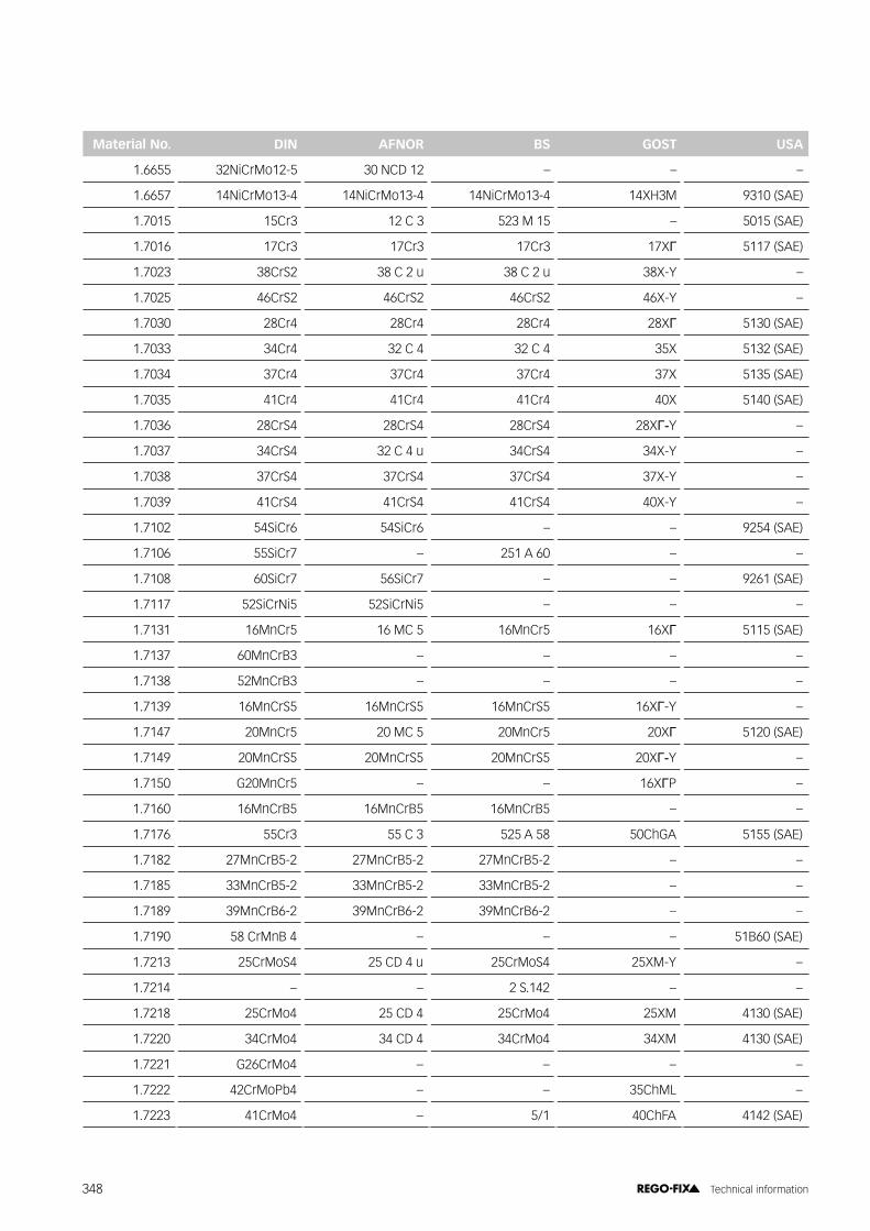
Material No. DIN AFNOR BS GOST USA
1.6655 32NiCrMo12-5 30 NCD 12 – – –
1.6657 14NiCrMo13-4 14NiCrMo13-4 14NiCrMo13-4 14XH3M 9310 (SAE)
1.7015 15Cr3 12 C 3 523 M 15 – 5015 (SAE)
1.7016 17Cr3 17Cr3 17Cr3 17X� 5117 (SAE)
1.7023 38CrS2 38 C 2 u 38 C 2 u 38X-Y –
1.7025 46CrS2 46CrS2 46CrS2 46X-Y –
1.7030 28Cr4 28Cr4 28Cr4 28X� 5130 (SAE)
1.7033 34Cr4 32 C 4 32 C 4 35X 5132 (SAE)
1.7034 37Cr4 37Cr4 37Cr4 37X 5135 (SAE)
1.7035 41Cr4 41Cr4 41Cr4 40X 5140 (SAE)
1.7036 28CrS4 28CrS4 28CrS4 28X��Y –
1.7037 34CrS4 32 C 4 u 34CrS4 34X-Y –
1.7038 37CrS4 37CrS4 37CrS4 37X-Y –
1.7039 41CrS4 41CrS4 41CrS4 40X-Y –
1.7102 54SiCr6 54SiCr6 – – 9254 (SAE)
1.7106 55SiCr7 – 251 A 60 – –
1.7108 60SiCr7 56SiCr7 – – 9261 (SAE)
1.7117 52SiCrNi5 52SiCrNi5 – – –
1.7131 16MnCr5 16 MC 5 16MnCr5 16X� 5115 (SAE)
1.7137 60MnCrB3 – – – –
1.7138 52MnCrB3 – – – –
1.7139 16MnCrS5 16MnCrS5 16MnCrS5 16X�-Y –
1.7147 20MnCr5 20 MC 5 20MnCr5 20X� 5120 (SAE)
1.7149 20MnCrS5 20MnCrS5 20MnCrS5 20X��Y –
1.7150 G20MnCr5 – – 16X�P –
1.7160 16MnCrB5 16MnCrB5 16MnCrB5 – –
1.7176 55Cr3 55 C 3 525 A 58 50ChGA 5155 (SAE)
1.7182 27MnCrB5-2 27MnCrB5-2 27MnCrB5-2 – –
1.7185 33MnCrB5-2 33MnCrB5-2 33MnCrB5-2 – –
1.7189 39MnCrB6-2 39MnCrB6-2 39MnCrB6-2 – –
1.7190 58 CrMnB 4 – – – 51B60 (SAE)
1.7213 25CrMoS4 25 CD 4 u 25CrMoS4 25XM-Y –
1.7214 – – 2 S.142 – –
1.7218 25CrMo4 25 CD 4 25CrMo4 25XM 4130 (SAE)
1.7220 34CrMo4 34 CD 4 34CrMo4 34XM 4130 (SAE)
1.7221 G26CrMo4 – – – –
1.7222 42CrMoPb4 – – 35ChML –
1.7223 41CrMo4 – 5/1 40ChFA 4142 (SAE)
348 Technical information

Material No. DIN AFNOR BS GOST USA
1.7225 42CrMo4 40 CD 4 42CrMo4 42XM 4140 (SAE)
1.7226 34CrMoS4 34 CD 3 u 34CrMoS4 34XM-Y 35XM –
1.7227 42CrMoS4 42 CD 4 u 42CrMoS4 42XM-Y –
1.7228 50CrMo4 50CrMo4 50CrMo4 50XM 4147 (SAE)
1.7233 42CrMo5-6 42CrMo5-6 42CrMo5-6 – –
1.7242 16CrMo4 15 CD 3.5 – – –
1.7243 18CrMo4 18 CD 4 18CrMo4 18XM –
1.7244 18CrMoS4 18CrMoS4 18CrMoS4 18XM-Y –
1.7262 15CrMo5 12 CD 4 FF – – –
1.7276 10CrMo11 CD 10 – – –
1.7281 16CrMo9-3 20 CD 8 – – –
1.7311 20 CrMo 2 – – – –
1.7315 37 CrMo 3 – – – –
1.7319 20MoCrS3 20MoCrS3 20MoCrS3 20XM-Y –
1.7320 20MoCr3 20MoCr3 20MoCr3 20XM –
1.7321 20MoCr4 20MoCr4 20MoCr4 20X�M 4118 (SAE)
1.7323 20MoCrS4 20MoCrS4 20MoCrS4 20X�M-Y –
1.7333 22CrMoS3-5 22CrMoS3-5 22CrMoS3-5 22X�M-Y –
1.7335 13 CrMo 4 4 13CrMo4-5 13CrMo4-5 13X; –
1.7341 G34CrMo4-4 – – – –
1.7353 1.7353 – B 5 – –
1.7354 G22CrMo5-4 – – – –
1.7355 G17CrMnMo5-5 – – – –
1.7357 G17CrMo5-5 – 621 – –
1.7361 32CrMo12 – 722 M 24 – –
1.7362 12 CrMo 19 5 X16CrMo5-1 625 12X5M 501 (AISI)
1.7363 GS-12 CrMo 19 5 – – – –
1.7365 GX15CrMo5 625 – –
1.7375 12CrMo9-10 12CrMo9-10 – – –
1.7377 G15CrMo9-10 – – – –
1.7379 G17CrMo9-10 – 622 – –
1.7380 10CrMo9-10 10CrMo9-10 10CrMo9-10 10X2M –
1.7381 12CrMo12-10 12 CD 12.10 – – –
1.7383 11CrMo9-10 10 CD 9-10 11CrMo9-10 – –
1.7386 X12CrMo9-1 – 629-470 – 504 (AISI)
1.7389 G-X 12 CrMo 10 1 – B 6 – –
1.7390 X15CrMo5-1 X15CrMo5-1 X15CrMo5-1 – –
1.7503 67 CrV 2 2 – – 70ChGFA –
349 Technical information

Material No. DIN AFNOR BS GOST USA
1.7511 22CrV3 – – – 6118 (SAE)
1.7701 51CrMoV4 51 CDV 4 – – –
1.7706 G17CrMoV5-10 – G17CrMoV5-10 – –
1.7707 30CrMoV9 – – 30Ch3MF –
1.7709 21CrMoV5-7 21CrMoV5-7 21CrMoV5-7 – –
1.7711 40CrMoV4-6 40CrMoV4-6 40CrMoV4-6 – –
1.7715 14MoV6-3 14Mo6 660 – –
1.8159 50 CrV 4 50 CV 4 51CrV4 50X�� 6150 (SAE)
1.8507 34CrAlMo5 CAD 6.12 – – –
1.8509 41CrAlMo7 – 905 M 39 38Ch2MJuA E 71400 (SAE)
2.4631 NiCr20TiAl – 2 HR 201 – HEV 5 (SAE)
2.4632 NiCr20Co18Ti – 2 HR 2 – HEV 6 (SAE)
2.4636 NiCo15Cr15MoAlTi – HR 4 – –
2.4639 SG-NiCr20 – NA 34 – –
2.4650 NiCo20Cr20MoTi – 2 HR 1 – –
2.4652 EL-NiCr26Mo – – – S 32654 (AISI)
2.4654 NiCr19Co14Mo4Ti – – – XEV-H (SAE)
2.4660 NiCr20CuMo – – – N 08020 (AISI)
2.4665 NiCr22Fe18Mo – HR 204 – –
2.4667 SG-NiCr19NbMoTi – NA 51 – –
2.4668 NiCr19Fe19Nb5Mo3 – – – XEV-I (SAE)
2.4669 NiCr15Fe7Ti2Al NiCr15Fe7TiAl NiCr15Fe7TiAl – 688 (AISI)
2.4806 SG-NiCr20Nb – NA 35 – –
2.4810 NiMo 30 Ni-Mo 28 ANC 15 – –
2.4816 NiCr15Fe – HR 208 – –
2.4819 NiMo16Cr15W Ni-Mo 16 Cr 15 – – –
2.4831 SG-NiCr21Mo9Nb – – – –
2.4851 NiCr23Fe – NiCr23Fe – –
2.4854 NiFe33Cr25Co – – S 35315 (AISI)
2.4856 NiCr22Mo9Nb – NA 21 – –
2.4858 NiCr21Mo – NA 16 – –
2.4867 NiCr60-15 – – Ch15N60 –
2.4869 NiCr 80 20 – – Ch20N80 –
2.4886 SG-NiMo16Cr16W – NA 48 – –
1.4889 NiCr28FeSiCe – NiCr28FeSiCe – –
2.4951 NiCr20Ti – 2 HR 504 – –
350 Technical information

AA-E Wrench head for standard locknutA-E AX Wrench head for slip-off proof locknutA-E M Wrench head for Mini locknutA-E MS Wrench head for Mini Speed locknutA-E MX Wrench head for intRlox® locknut|#;��� *���������@�'����������� �������������"���A-FLS Roller-wrench-headANSI American national standards instituteAPC Clamping insert for manual powRgrip®
clamping unit PGCAPG Clamping insert for automatic powRgrip®
clamping unit PGUAT1 Taper angle tolerance – gauge qualityAT3 taper angle toleranceATL Tangs for Morsetaper shanks DIN 228-C
BBT Steep taper Norm BT MAS 403BT+ Steep taper Norm BT+ licensed by
BIG Daishowa Seiki
CC3 – C8 REGO-FIX CAPTO sizesCAPTO Interface standard Capto licensed by
Sandvik CoromantCAT Steep taper norm CAT (ASME 5.50)CC Chip cover for reduction sleevesCGA Coolant thread adapter for cylindrical
toolholdersCPS Cleaning paper set for powRgrip® taper cleanerCRYO Cryogen coolantCTPG Collet tray for powRgrip® colletsCYD Cylindrical shank double toolholderCYDF Cylindrical shank double toolholder with
�������������CYL Cylindrical shank toolholder�±j>� �����@����������"��������@���'����������������
DDS Sealing diskDSR Tray for Sealing disks
EE Wrench for standard locknutE A Wrench for locknut with external threadE AX Wrench for slip-off proof locknutE M Wrench for Mini locknutE MS Wrench for Mini Speed locknutE MX Wrench for intRlox® locknut;��� *������'����������� �������������"���EHS Extraction tool for reduction sleeves;�� ;������@��@�����������������J����ER ER collet DIN 6499 (E collet REGO-FIX)ER MS ER locknut Mini SpeedER NC Cylindrical toolholder with shank NC lathe
ERA / Zero-Z Toolholder with minimal gauge length and internal locknut
ERAX Slip-off proof locknut with external threadERAXC Slip-off proof locknut with external thread for
sealing disksERB Locknut with friction bearingERBC Locknut with friction bearing for sealing disksERC Locknut for sealing disksER-DM ER collet metalically sealedER-GB Tapping Collets with square without axial
compensationERM Locknut with Mini threadERMC Locknut with Mini thread for sealing disksERMX Slip-off proof Mini locknut intRlox®
ERMXC Slip-off proof Mini locknut intRlox® for sealing disks
;�#��� ;��������������������������������������
FFDS Wrench for Universal Shellmill / Facemill HoldersFWR Balancing ring
GG-A Grip barG-AS Grip bar shortGSF Tapping holder
HH Designed for FWRHD Heavy dutyHi-Q Clamping nut balanced and surface treated
(impregnated)HPC High-performance-cuttingHS Reduction sleeveHSC High-speed-cuttingHSK Hollow taper shankHSK-FP Hollow taper shank form F with pin
IIKZ Coolant troughINOX Stainless steelintRlox® Slip-off proof nut and wrench$�=�Y���||�� }������@���� ����||��= ���� ���
KKBF Drill chuckKFD Universal Shellmill / Facemill HoldersKS Coolant diskKSR Coolant tube
LL Clamping nut with left handed thread
Terminology A – L
351 Technical information

MMA Shell Mill ArborMB Microbore colletMBX Microbore collet with clamping range – stainlessMFD Micro friction dampeningMK Morse Taper DIN 228ML Multi Line ��� ����������������" ���� ����������������"� ��������������������������MQL Minimum quantity lubricationMR micRun®�����������������Y����MRC micRun® locknut for sealing disksMRM micRun® Mini locknutMRMC micRun® Mini locknut for sealing disksMWZ Assembly tool for sealing disks DS / ER 11
NNC Cylindrical toolholder with shank NC latheNCT No thread for coolant tubeNL powRgrip® collets PG-L cannot be usedNm Newton meter
OOM Steep taper toolholders without drive key slots
PPCM ET1 Tapping collet with axial compensationPG powRgrip®
PGC Manual powRgrip® clamping unitPG-CF powgrip®��������������������� ��������������
coolingPG-L powRgrip® collet for long tool shanksPG-MB powRgrip® microbore colletPG-S powRgrip® collet for short tool shanksPG-SG powRgrip® secuRgrip® collet for pull-out
protectionPGST powgrip® short tail collet for PGST systemPG-T powRgrip® collet for boring barsPG-TAP powRgrip® tapping colletPG-TW powRgrip® collet thin walled with limited
life-timePGU Automatic powRgrip® clamping unitPGU 9500 A powRgrip® clamping unit USA (115 V)PGU 9500 E powRgrip® clamping unit Europe (230 V)PGU 9500 J powRgrip® clamping unit Japan (100 V)PH Floating chuckPHC Floating chuck for internal coolant supply���#�� ��;<=#>$?��|�}=�������������"� ������������
coolant supply
R��� ����� ������ ������������RBA reCool® ball adapterRCR reCool® rotaryRCS reCool® staticREGO-FIX Swiss company for tool holding solutions
RHS reCool® hose with protector springRRA reCool® aluminium ring adapterRVA reCool®�U�´���^�'�����#���������RVG reCool®��������������#���������
SSG secuRgrip® available for PG and ERSGI secuRgrip® threaded insertSGN-PG secuRgrip® safety nutSH Automotive Shank toolholders DIN 6327-CSK Steep taperSKR Key for coolant tubeSSM Quick-change setting ringSSY Soft-Synchro tapping holder
TTCD Brush head for taper cleaning deviceTCD-BU Base unit taper cleaning deviceTKCP powRgrip® taper cleaner with cleaning paperTSD TORX Torque screwdriver
VV-E AX Slip-off proof extensionV-E MX Slip-off proof extension intRlox®
VEW Presetting tool for powRgrip® toolholders
�WA Tool adapterWD Endmill toolholder (Weldon)WMH Tool assembly indexing
XX Slip-off proofXL Extra long toolholder
ZZWT Tray for ER collets (metric)ZZT Tray for ER collets (inch)
Terminology M – Z
352 Technical information
<<<&��� ��%&( 0362.00251 / ENG