Table of Contents - Axon Download Area
51
Committed. SLD100/120/200/220 Solid state drive based SD-SDI uncompressed long time delay with optional two individual output delays and optional logo insertion Installation, Operation and Upgrade manual
-
Upload
khangminh22 -
Category
Documents
-
view
0 -
download
0
Transcript of Table of Contents - Axon Download Area
Committed.
SLD100/120/200/220
Solid state drive based SD-SDI uncompressed long time delay with optional two individual output delays and
optional logo insertion
Installation, Operation and Upgrade manual

Lange Wagenstraat 55
NL-5126 BB Gilze
The Netherlands
Phone: +31 161 850 450
Fax: +31 161 850 499
E-mail: [email protected]
Web: www.axon.tv
TECHNICAL MANUAL
SLD100 SLD120 SLD200 SDL220

1
WARNING: TO REDUCE THE RISK OF FIRE OR
ELECTRICAL SHOCK, DO NOT EXPOSE THIS
APPLIANCE TO RAIN OR MOISTURE
● ALWAYS disconnect your entire system from the AC mains before cleaning any component. The product frame (SFR18, SFR08 or SFR04) must be terminated with three-conductor AC mains power cord that includes an earth ground connection. To prevent shock hazard, all three connections must always be used. ● NEVER use flammable or combustible chemicals for cleaning components. ● NEVER operate this product if any cover is removed. ● NEVER wet the inside of this product with any liquid. ● NEVER pour or spill liquids directly onto this unit. ● NEVER block airflow through ventilation slots. ● NEVER bypass any fuse. ● NEVER replace any fuse with a value or type other than those specified. ● NEVER attempt to repair this product. If a problem occurs, contact your local Axon distributor. ● NEVER expose this product to extremely high or low temperatures. ● NEVER operate this product in an explosive atmosphere. Warranty: Axon warrants their products according to the warranty policy as described in the general terms. That means that Axon Digital Design BV can only warrant the products as long as the serial numbers are not removed. Copyright © 2001 – 2013 AXON Digital Design B.V. Date created: 19-06-2012 Date last revised: 05-12-2013 Axon, the Axon logo and Synapse are trademarks of Axon Digital Design B.V. This product complies with the requirements of the product family standards for audio, video, audio-visual entertainment lighting control apparatus for professional use as mentioned below.
EN60950 EN55103-1: 1996 EN55103-2: 1996
Safety Emission Immunity
Axon Digital Design SLD100/120/200/220
Tested To Comply
With FCC Standards
FOR HOME OR OFFICE USE
This device complies with part 15 of the FCC Rules Operation is subject to the following two conditions: (1) This device may cause harmful interference, and (2) This device must accept any interference received, including interference that may cause undesired operation.

2
Table of Contents Introduction to Synapse 5
An Introduction to Synapse 5 Local Control Panel 5 Remote Control Capabilities 5
Unpacking and Placement 6 Unpacking 6 Placing the card 6 (Re)placing Solid State Disk 6 Axon approved disks 7
A Quick Start 8 When powering-up 8 Changing settings and parameters 8 Front Panel Control 8 Example of changing parameters using front panel control 9 Axon Cortex Software 10 Menu Structure Example 10
The SLD Card 11 Introduction 11 Features 11 Applications 12 Block schematic 12
Settings Menu 13 Introduction 13 Out-Frmt 13 RunIn-Frames 13 RunOut-Frames 13 Lock-Mode 13 Ref-Type 13 Time-Source 13 Output1-enable 13 Output1-Overlay 14 Delay1_Hours 14 Delay1_Mins 14 Delay1_Seconds 14 Delay1_Frames 14 Output2-enable 14 Output2-Overlay 15 Delay2_Hours 15 Delay2_Mins 15 Delay2_Seconds 15 Delay2_Frames 15 Panic_Fill 15 Monitor-Temp 15 Monitor-Disks 15 Marker 16 PrstEditView 16 #Marker-Val 16 #Marker-Cmd 16 #Marker-Name 16 #Marker-H 16 #Marker-M 16 #Marker-S 16 #Marker-F 16 LogoA1_Act 17 LogoA1_edit 17 #LogoA1-Name 17 #LogoA1-Origin 17 #LogoA1-XPos 17 #LogoA1-YPos 17 #LogoA1-Width 17 #LogoA1-Height 17 #LogoA1-Fade-In 18 #LogoA1-Fade-Out 18 LogoA2_Act 18 LogoA2_edit 18 #LogoA2-Name 18 #LogoA2-Origin 18 #LogoA2-XPos 18
3
#LogoA2-YPos 18 #LogoA2-Width 18 #LogoA2-Height 19 #LogoA2-Fade-In 19 #LogoA2-Fade-Out 19 LogoB1_Act 19 LogoB1_edit 19 #LogoB1-Name 19 #LogoB1-Origin 19 #LogoB1-XPos 19 #LogoB1-YPos 19 #LogoB1-Width 20 #LogoB1-Height 20 #LogoB1-Fade-In 20 #LogoB1-Fade-Out 20 LogoB2_Act 20 LogoB2_edit 20 #LogoB2-Name 20 #LogoB2-Origin 20 #LogoB2-XPos 20 #LogoB2-YPos 21 #LogoB2-Width 21 #LogoB2-Height 21 #LogoB2-Fade-In 21 #LogoB2-Fade-Out 21 NTPServer 21 NTPOffsetH 21 NTPOffsetM 21 IP_Conf0 21 mIP0 21 mNM0 21 mGW0 21 NetwPrefix0 21
Status Menu 22 Introduction 22 SDI-Input_1 22 SDI-Input_2 22 Buffer-Size 22 Buffer-Fill 22 Marker1-Pos ~ Marker4_Pos 22 GPI-Active 22 Disk1_Status 23 Disk1_Model 23 Disk1_Serial 23 Disk1_Size 23 Disk1_AvgRead 23 Disk1_AvgWrite 23 Disk2_Status 23 Disk2_Model 23 Disk2_Serial 23 Disk2_Size 24 Disk2_AvgRead 24 Disk2_AvgWrite 24 CPU_Env_Temp 24 CPU_Core_Temp 24 FPGA_Env_Temp 24 FPGA_Core_Temp 24 FPGA_Fan 24 IP_Addr0 24 IP0 24 MAC0 24 NM0 24 GW0 24
Events Menu 25 Introduction 25 What is the Goal of an event? 25 Events 25 Announcements 25 What information is available in an event? 25 The Message String 25 The Tag 25 Defining Tags 26 The Priority 26

4
The Address 26
LED Indication 27 Introduction 27 Error LED 27 Input_1 LED 27 Input_2 LED 27 ANC Data LED 27 Reference LED 27 Data Error LED 27 Connection LED 27 Error LED 27
Connector Panels 28 D-sub pinning 28
Quad speed bus explained 29 Some examples 31
Uploading logos using cortex 34 Introduction 34 Uploading files 34
Uploading logos using WebDav or FTP. 36 Introduction 36 WebDAV 36 FTP 36 Uploading files using Windows XP 36
Reprogramming SLDxxx modules 40 Before you start 40 Functionality explanation 40 Choosing .spf files 40 Requirements 40 Using Cortex help files 40 Precautions 41 Backup your settings 41 At your own risk 41 Setting up card 42 Opening the upload window 43 Selecting the spf file 43 Selecting the right card(s) 44 Starting the upload process 44 Ready programming 45 Update Cortex form (CLF file) 45 Testing 45
GNU Public License version 2 46
Contacting Axon costumer support 49
5
1 Introduction to Synapse An Introduction to
Synapse Synapse is a modular system designed for the broadcast industry. High density, intuitive operation and high quality processing are key features of this system. Synapse offers a full range of converters and processing modules. Please visit the AXON Digital Design Website at www.axon.tv to obtain the latest information on our new products and updates.
Local Control
Panel The local control panel gives access to all adjustable parameters and provides status information for any of the cards in the Synapse frame, including the Synapse rack controller. The local control panel is also used to back-up and restore card settings. Please refer to the rack controler manuals for a detailed description of the local control panel, the way to set-up remote control over IP and for frame related settings and status information.
Remote Control
Capabilities The remote control options are explained in the rack controller manual. The method of connection to a computer using Ethernet is also described in the ERC/ERS/RRC/RRS manual.
! CHECK-OUT: “AXON CORTEX” SOFTWARE WILL INCREASE SYSTEM FLEXIBILITY OF ONE OR MORE SYNAPSE FRAMES
Although not required to use Cortex with a Synapse frame, you are strongly advised to use a remote personal computer or laptop PC with Axon Cortex installed, as this increases the ease of use and understanding of the modules.

6
2 Unpacking and Placement Unpacking The Axon Synapse card must be unpacked in an anti-static
environment. Care must be taken NOT to touch components on the card – always handle the card carefully by the edges. The card must be stored and shipped in anti-static packaging. Ensuring that these precautions are followed will prevent premature failure from components mounted on the board.
Placing the card The Synapse card can be placed vertically in an SFR18 frame or
horizontally in an SFR08 frame. We advice not to use the SLD in an SFR04! Locate the two guide slots to be used, slide in the mounted circuit board, and push it firmly to locate the connectors.
The SLD100 and SLD200 consist out of two cards, the processing card and the card containing the SSD’s. The cards have to be placed next to each other with the SSD card one slot number lower than the processing card. This means in an SFR18 the SSD card has to be inserted one slot on the left hand side of the processing card. In an SFR08 do not try to insert the processing card in slot 5 and the SSD in slot 4. This will not work!
Correct insertion of card is essential as a card that is not located properly may show valid indicators, but does not function correctly.
NOTE: On power up all LED’s will light for a few seconds, this is
the time it takes to initialise the card.
(Re)placing Solid State Disk
The Solid state disks have to be manually (re)placed. To do this, synapse card which contains the SSD’s will have to be pulled out of the frame. This will cause output downtime!
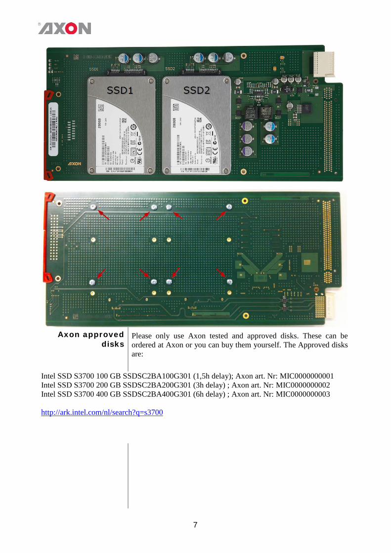
After reseating the card, the buffer will be cleared and the recording starts from the beginning! SSD1 is the disk closest to the card grip. SSD2 is the disk closest to the card connector, clearly indicated on the PCB itself. Use a small Philips screwdriver to unscrew the 4 screws of the disk that requires replacement. Carefully slide the disk out of the SATA connectors. Take the new disk and gently slide it into the SATA connectors. When the disk is in place, screw the disk steadfast onto the board with the 4 screws (M3*5CK). Below pictures (next page) shows the position of the disks and the screws of each SSD on the bottom side of the card.
7
Axon approved
disks Please only use Axon tested and approved disks. These can be ordered at Axon or you can buy them yourself. The Approved disks are:
Intel SSD S3700 100 GB SSDSC2BA100G301 (1,5h delay); Axon art. Nr: MIC0000000001 Intel SSD S3700 200 GB SSDSC2BA200G301 (3h delay) ; Axon art. Nr: MIC0000000002 Intel SSD S3700 400 GB SSDSC2BA400G301 (6h delay) ; Axon art. Nr: MIC0000000003 http://ark.intel.com/nl/search?q=s3700
8
3 A Quick Start When powering-
up On powering up the Synapse frame, the card set will use basic data and default initialisation settings. All LED’s will light during this process. After initialisation, several LED’s will remain lit – the exact number and configuration is dependent upon the number of inputs connected and the status of the inputs.
Changing settings
and parameters The front panel controls or the Axon Cortex can be used to change settings. An overview of the settings can be found in chapter 5, 6 and 7 of this manual.
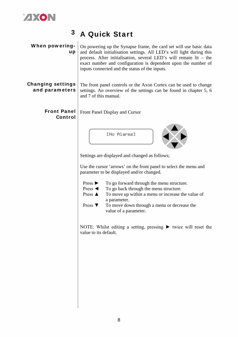
Front Panel
Control Front Panel Display and Cursor
Settings are displayed and changed as follows;
Use the cursor ‘arrows’ on the front panel to select the menu and parameter to be displayed and/or changed.
Press ► To go forward through the menu structure. Press ◄ To go back through the menu structure. Press ▲ To move up within a menu or increase the value of
a parameter. Press ▼ To move down through a menu or decrease the
value of a parameter.
NOTE: Whilst editing a setting, pressing ► twice will reset the
value to its default.
[No Alarms]
9
Example of changing
parameters using front panel control
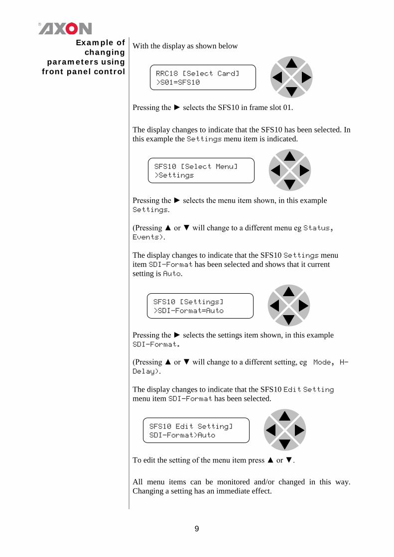
With the display as shown below
Pressing the ► selects the SFS10 in frame slot 01.
The display changes to indicate that the SFS10 has been selected. In this example the Settings menu item is indicated.
Pressing the ► selects the menu item shown, in this example Settings. (Pressing ▲ or ▼ will change to a different menu eg Status, Events). The display changes to indicate that the SFS10 Settings menu item SDI-Format has been selected and shows that it current setting is Auto.
Pressing the ► selects the settings item shown, in this example SDI-Format. (Pressing ▲ or ▼ will change to a different setting, eg Mode, H-Delay). The display changes to indicate that the SFS10 Edit Setting menu item SDI-Format has been selected.
To edit the setting of the menu item press ▲ or ▼.
All menu items can be monitored and/or changed in this way. Changing a setting has an immediate effect.
RRC18 [Select Card] >S01=SFS10
SFS10 [Select Menu] >Settings
SFS10 [Settings] >SDI-Format=Auto
SFS10 Edit Setting] SDI-Format>Auto
10
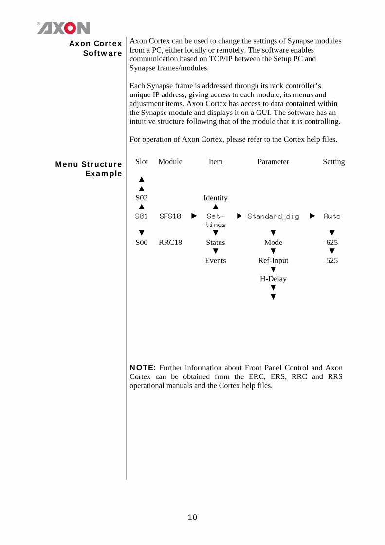
Axon Cortex Software
Axon Cortex can be used to change the settings of Synapse modules from a PC, either locally or remotely. The software enables communication based on TCP/IP between the Setup PC and Synapse frames/modules. Each Synapse frame is addressed through its rack controller’s unique IP address, giving access to each module, its menus and adjustment items. Axon Cortex has access to data contained within the Synapse module and displays it on a GUI. The software has an intuitive structure following that of the module that it is controlling. For operation of Axon Cortex, please refer to the Cortex help files.
Menu Structure
Example Slot Module Item Parameter Setting
▲ ▲
S02 Identity ▲ ▲ S01 SFS10 ► Set-
tings ► Standard_dig ► Auto
▼ ▼ ▼ ▼ S00 RRC18 Status Mode 625
▼ ▼ ▼ Events Ref-Input 525 ▼ H-Delay ▼ ▼
NOTE: Further information about Front Panel Control and Axon Cortex can be obtained from the ERC, ERS, RRC and RRS operational manuals and the Cortex help files.
11
4 The SLD Card Introduction The SLD100/200 family are a long time SD-SDI uncompressed
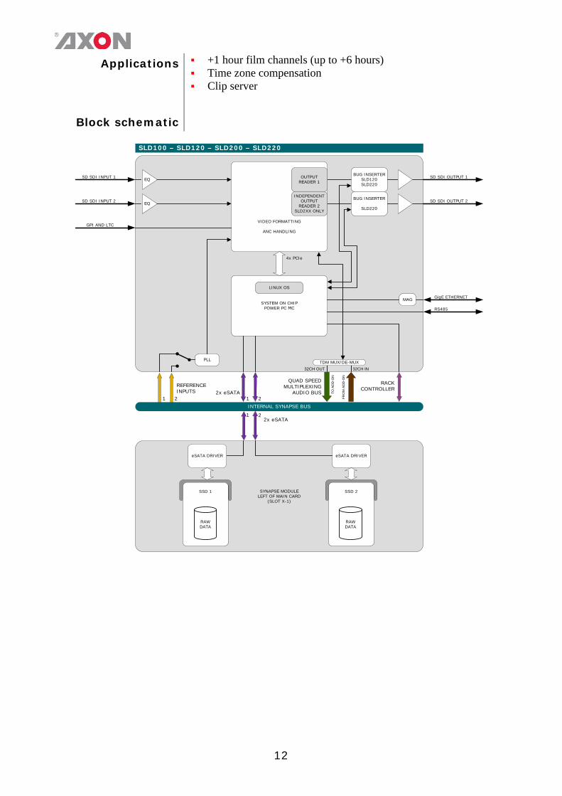
baseband video delays. It can store and delay SD material, including all blanking, as RAW data. The 100 has one delayed output the 200 has 2 delayed outputs individually adjustable as for instance +1 hour and +2 hour. The SLDx20 adds a bug inserter for channel ident applications but also as an emergency overlay with its full frame capability. These long time delays can store and delay up to 6 hours of SDI material depending on the size of disks, bitrates and ANC data. (with 2x 400G drives) The use of SSD disks makes this unit extremely reliable, low power and it will provide low maintenance.1) The delay length is depending on the used size of the SSD disks giving increased capacity at low cost in upcoming years. MTBF of disks is dependent on storage capacity and brand (type). Twice the storage than needed means theoretical twice the lifecycle as this is coupled to the amount of write cycles, not read cycles. Compared to competitive server based solutions the SLD100 family can be considered as very GREEN. The power consumption of this dual slot device is approximately 40W. This is a 10 fold saving of a comparable server based unit that draws > 350W average saving a significant amount of money due to the low operating power and accompanying air conditioning. The hardware of the long time delays is fully 3Gb/s and HD-SDI capable ensuring future proof investment for later planned updates into 3Gb/s and HD
Features
SLD100 = basic single channel delay unit SLD120 = as SLD100 with additional bug inserter SLD200 = dual output delay unit (fully independent outputs with
independent delay settings) SLD220 = as SLD200 with two additional bug inserters Capable of delaying video up to 6 hours (with 2 400G disks), ANC
data and disk space Two preset banks per bug inserter (SLD120/220 only) with
memory for 16 bugs and 4 full screen stills independent per output (two keyers)
Output freezes on disk failure Targa logo support SSD20 card added for SMART disk status RAW delay Compatible with 270 Mbit/s (SMPTE 259M) 50 and 59.94Hz Full control and status monitoring through the front panel of the
SFR04/SFR08/SFR18 frame and the Ethernet port (ACP)
12
Applications +1 hour film channels (up to +6 hours) Time zone compensation Clip server
Block schematic
SLD100 – SLD120 – SLD200 – SLD220
INTERNAL SYNAPSE BUS
RACK CONTROLLER
REFERENCEINPUTS
1 2
PLL
VIDEO FORMATTING
ANC HANDLING
SD SDI INPUT 1 EQ
SD SDI INPUT 2
SD SDI OUTPUT 1
SYSTEM ON CHIPPOWER PC ΜC
EQ SD SDI OUTPUT 2
4x PCIe
MAG GigE ETHERNET
RS485
QUAD SPEED MULTIPLEXING
AUDIO BUS
32CH OUT 32CH IN
TO A
DD
-ON
FRO
M A
DD
-ON
TDM MUX/DE-MUX
LINUX OS
2x eSATA1 2
SYNAPSE MODULE LEFT OF MAIN CARD
(SLOT X-1)
eSATA DRIVER
2x eSATA21
eSATA DRIVER
SSD 1 SSD 2
BUG INSERTERSLD120SLD220
BUG INSERTER
SLD220
OUTPUT READER 1
INDEPENDENT OUTPUT
READER 2SLD2XX ONLY
RAWDATA
RAWDATA
GPI AND LTC

13
5 Settings Menu Introduction The settings menu displays the current state of each SLD setting and
allows you to change or adjust it. Settings can be changed using the front panel of the Synapse frame (SFR18 or SFR08) or with Cortex. Also the Synapse or Cortex control panels can be used. Please refer to chapter 3 for information on the Synapse front panel control and Cortex.
Note: All items preceded with a #-sign are part of the presets.
Out-Frmt With Out-Frmt you can set what the output should be. This setting is only used for the delay options. This will not up/down/cross convert your input signal. Possible settings are: SD525 SD625
RunIn-Frames Here you set what should be on the output during run-in (the time
between input and the start of the delayed output). You can choose the output during this period to be a colorbar, black, grey, green or a freeze of the first frame to be played. Default is Freeze.
RunOut-Frames Here you set what should be on the output during run-out (The time after
all the Record-Run content has been played). You can choose the output during this period to be a colorbar, black, grey or green. Default is Colorbar.
Lock-Mode Lock-Mode determines to what source the card is locked. This setting is
fixed to reference input 1 (Ref1).
Ref-Type Sets the type of incoming reference. This setting is fixed to Bi-Level.
Time-Source Here you set the time synchronization source. Currently fixed to NTP.
Output1-enable Enables or disables output 1. What the output will be in delay, with respect to the input, is set with the settings with a ‘Delay1_’-prefix. Can also be set to Pause (which will pause the output on the current frame) or to Edit (the output jumps to the active marker that can be modified)
14
Output1-Overlay The SLD has on screen display which can show different kinds of information as overlay over video output 1. For the SLD120 and SLD220 you can set a logo as overlay on output 1. These are the possible overlays:
HW-status: showing CPU Environment temp, CPU core temp, FPGA Environment temp, FPGA Core temp and FPGA fan speed.
Disk-Status: showing overall SSD status (tested mean the disk is tested Axon approved, untested means the disk is not tested and thus not approved by Axon), SSD model, SSD serial number, SSD size (in GB), Average reading bitrate and average writing bitrate.
Buffer-Status: showing the status of the buffer and the markers. The total size of the buffer (the maximum achievable delay), the amount of buffer which is currently filled, The position of Output 1 and the position of Ouput 2. Next to these 4 buffer statuses the 4 marker values are indicated. In the graphical display of the buffer the markers are indicated in the respective colors.
Logo-InserterA: Overlay the logo(s) which is set with the Logo-inserterA settings (SLD120 and SLD220 only).
Logo-InserterB: Overlay the logo (s)which is set with the Logo-inserterB settings SLD220 only).
Panic1 ~ Panic4: Four selectable full screen logo’s intended for emergency application. (SLD120 and SLD220 only).
Delay1_Hours With this setting you set the video delay hours of output 1 (with respect to
the input).
Delay1_Mins Here you set the video delay minutes of output1 (with respect to the input)
Delay1_Seconds Here you set the video delay seconds of output1 (with respect to the input)
Delay1_Frames Here you set the video delay frames of output1 (with respect to the input)
Output2-enable Enables or disables output 2. On the SLD100/120 the delay of output 2 is the same as the delay of output 1, set with the Delay1_xxx settings. With the SLD200/220 output 2 can have a different delay than output 1. What the output will be in delay, with respect to the input, is set with the settings with a ‘Delay2_’-prefix in the SLD200/220. When the delay of output 2 on a SLD200/220 should be the same as output 1, you can set this setting to Delay1. Can also be set to Pause (which will pause the output on the current frame, only applicable for an SLD200/220) or to Edit (the output jumps to the active marker that can be modified, also only applicable for an SLD200/220)
15
Output2-Overlay The SLD has on screen display which can show different kinds of information as overlay over video output 2. For the SLD120 and SLD220 you can set a logo as overlay on output 2. The same overlays are possible as explained in Output1_Overlay.
Delay2_Hours
(SLD200/220 only) With this setting you set the video delay hours of output 2 (with respect to the input).
Delay2_Mins
(SLD200/220 only) Here you set the video delay minutes of output 2 (with respect to the input)
Delay2_Seconds (SLD200/220 only)
Here you set the video delay seconds of output 2 (with respect to the input)
Delay2_Frames
(SLD200/220 only) Here you set the video delay frames of output 2 (with respect to the input)
Panic_Fill Sets the fill mode of the Panic (emergency) overlay.
Set to Fit will respect the incoming aspect ratio and fill the window using the maximum available length or width and leaving the empty areas black.
Set to Zoom, the screen will be zoomed in, with respect to the incoming aspect ratio, causing the picture to be cut off on the sides when the window is not of the same aspect ratio.
Set to Anamorphic, the picture will be set to fill the entire window but when the input aspect ratio is not the same as the aspect ratio of the window, the view will be anamorphic.
In Raw the logo is displayed without adjustments.
Monitor-Temp With this setting you can change the way the temperature is measured. Can be set to On (constantly monitor the temperatures and update the temperature status items), Once (measure the temperatures and update the temp status items once, after which this setting returns of off) or Off (don’t update the temp statuses).
Monitor-Disks With this setting you can change the way the disks are checked. Can be
set to On (constantly monitors the statuses of the disks and updates the disk status items), Once (check the disk status and update the disk status items once, after which this setting returns to off) or Off (don’t update the disk statuses).
16
Marker This is the sort-of preset master for the marker settings. There are 4 marker presets: Marker_1, Marker_2, Marker_3 and Marker_4. With this setting you select which marker you want to view and/or change the settings of. Settings with a ‘#Marker-‘ prefix (further down the menu) are all part of this preset.
PrstEditView The markers function as a preset. With this setting set to Follow
Active, the Marker settings will follow the active marker when the active Marker is changed. This to avoid confusion when changing the active. Set to Independent the Marker setting will not automatically follow active marker changes. By default set to Follow Active.
#Marker-Val This is the actual value of the marker (selected with the Marker preset
master setting). The value in the classic view is set in frames (up to 2147483647 frames). Please use the Cortex CLF of the SLD to change this setting in a more human-readable format (hours, minutes, seconds, frames).
#Marker-Cmd There are a few default commands which you can perform with the
marker presets: - None: do nothing with the marker. - Mark Inp: the value of the marker is set to resemble the current
input position. - Set Delay1: The ‘Delay1_’ settings are set to resemble the
marker value. In other words: output 1 will start playing from the point of the marker.
- Set Delay2 (SLD200 only): The ‘Delay2_’ settings are set to resemble the marker value. In other words: output 2 will start playing from the point of the marker.
- Clear: completely clear the marker value (set to -1).
#Marker-Name With this setting you can give a name to the marker selected with the marker preset master setting. Maximum of 16 characters is allowed.
#Marker-H Here you can set the marker position in hours
#Marker-M Here you can set the marker position in minutes
#Marker-S Here you can set the marker position in seconds
#Marker-F Here you can set the marker position in frames
17
LOGO-INSERTER
LogoA1_Act (SLD120/220 only)
With this active preset it is possible to select presets of logo A1 for the processed output (8 preset available). These presets will have an instant effect on the output. If the menu item is preceded by ‘#LogoA1-’, it is possible to add this setting to a preset. The presets are stored in memory. It is also possible to change factory presets. Changing these presets has direct effect on the processed output.
LogoA1_edit (SLD120/220 only)
With the edit preset item it is possible to create your own presets for logo A1 without the applied changes having any instant effect on the processed output. There are 8 possible offline adjustable presets. You can freely change the selected edit preset, without the active preset being set to another setting. It will have no immediate effect on the processed output, until LogoA1_act is changed to the setting you adjusted with LogoA1_edit.
#LogoA1-Name
(SLD120/220 only) This setting displays the first 16 characters of the filename for the current LogoA1_edit logo. This is a read only item. If no logo is shown, one of the following messages are shown: No file: There is no file to be displayed, Unknown file format: File format isn’t recognized/suitable VRAM, Out of Mem: Video RAM is out of memory. Nevertheless,
files are being stored on the flash disk. Error: file corruption: Uploaded file is corrupt and will be
renamed to <filename.extension>.error
#LogoA1-Origin (SLD120/220 only)
With this setting you can change the #LogoA1-XPos and #LogoA1-YPos settings to default to Top-Left, Top-Right, Bottom-Left, Bottom-Right or Center positions. Default is Top-Left.
#LogoA1-XPos
(SLD120/220 only) This setting sets the horizontal position of logo A1. Can be ranging from -2047px till 2048 pixels. Default is pixel 0.
#LogoA1-YPos
(SLD120/220 only) This setting sets the vertical position of logo A1. Can be ranging from -2047px till 2048 pixels. Default is pixel 0.
#LogoA1-Width
(SLD120/220 only) This menu item indicates the width of the image currently in use by logo A1. This is a read only item.
#LogoA1-Height (SLD120/220 only)
This menu item indicates the height of the image currently in use by logo A1. This is a read only item.
18
#LogoA1-Fade-In (SLD120/220 only)
This item sets the fade-in time of logo A1 in frames, ranging from 0 to 200 frames. 0 frames is default.
#LogoA1-Fade-Out (SLD120/220 only)
This item sets the fade-out time of logo A1 in frames, ranging from 0 to 200 frames. 0 frames is default.
LogoA2_Act
(SLD120/220 only) With this active preset it is possible to select presets of logo A2 for the processed output (8 preset available). These presets will have an instant effect on the output. If the menu item is preceded by ‘#LogoA2-’, it is possible to add this setting to a preset. The presets are stored in memory. It is also possible to change factory presets. Changing these presets has direct effect on the processed output.
LogoA2_edit (SLD120/220 only)
With the edit preset item it is possible to create your own presets for logo A2 without the applied changes having any instant effect on the processed output. There are 8 possible offline adjustable presets. You can freely change the selected edit preset, without the active preset being set to another setting. It will have no immediate effect on the processed output, until LogoA2_act is changed to the setting you adjusted with LogoA2_edit.
#LogoA2-Name
(SLD120/220 only) This setting displays the first 16 characters of the filename for the current LogoA2_edit logo. This is a read only item. If no logo is shown, one of the following messages are shown: No file: There is no file to be displayed, Unknown file format: File format isn’t recognized/suitable VRAM, Out of Mem: Video RAM is out of memory. Nevertheless,
files are being stored on the flash disk. Error: file corruption: Uploaded file is corrupt and will be
renamed to <filename.extension>.error
#LogoA2-Origin (SLD120/220 only)
With this setting you can change the #LogoA2-XPos and #LogoA2-YPos settings to default to Top-Left, Top-Right, Bottom-Left, Bottom-Right or Center positions. Default is Top-Left.
#LogoA2-XPos
(SLD120/220 only) This setting sets the horizontal position of logo A2. Can be ranging from -2047px till 2048 pixels. Default is pixel 0.
#LogoA2-YPos
(SLD120/220 only) This setting sets the vertical position of logo A2. Can be ranging from -2047px till 2048 pixels. Default is pixel 0.
#LogoA2-Width
(SLD120/220 only) This menu item indicates the width of the image currently in use by logo A2. This is a read only item.
19
#LogoA2-Height (SLD120/220 only)
This menu item indicates the height of the image currently in use by logo A2. This is a read only item.
#LogoA2-Fade-In (SLD120/220 only)
This item sets the fade-in time of logo A2 in frames, ranging from 0 to 200 frames. 0 frames is default.
#LogoA2-Fade-Out (SLD120/220 only)
This item sets the fade-out time of logo A2 in frames, ranging from 0 to 200 frames. 0 frames is default.
LogoB1_Act
(SLD220 only) With this active preset it is possible to select presets of logo B1 for the processed output (8 preset available). These presets will have an instant effect on the output. If the menu item is preceded by ‘#LogoB1-’, it is possible to add this setting to a preset. The presets are stored in memory. It is also possible to change factory presets. Changing these presets has direct effect on the processed output.
LogoB1_edit (SLD220 only)
With the edit preset item it is possible to create your own presets for logo B1 without the applied changes having any instant effect on the processed output. There are 8 possible offline adjustable presets. You can freely change the selected edit preset, without the active preset being set to another setting. It will have no immediate effect on the processed output, until LogoB1_act is changed to the setting you adjusted with LogoB1_edit.
#LogoB1-Name
(SLD220 only) This setting displays the first 16 characters of the filename for the current LogoB1_edit logo. This is a read only item. If no logo is shown, one of the following messages are shown: No file: There is no file to be displayed, Unknown file format: File format isn’t recognized/suitable VRAM, Out of Mem: Video RAM is out of memory. Nevertheless,
files are being stored on the flash disk. Error: file corruption: Uploaded file is corrupt and will be
renamed to <filename.extension>.error
#LogoB1-Origin (SLD220 only)
With this setting you can change the #LogoB1-XPos and #LogoB1-YPos settings to default to Top-Left, Top-Right, Bottom-Left, Bottom-Right or Center positions. Default is Top-Left.
#LogoB1-XPos
(SLD220 only) This setting sets the horizontal position of logo B1. Can be ranging from -2047px till 2048 pixels. Default is pixel 0.
#LogoB1-YPos
(SLD220 only) This setting sets the vertical position of logo B1. Can be ranging from -2047px till 2048 pixels. Default is pixel 0.

20
#LogoB1-Width (SLD220 only)
This menu item indicates the width of the image currently in use by logo B1. This is a read only item.
#LogoB1-Height (SLD220 only)
This menu item indicates the height of the image currently in use by logo B1. This is a read only item.
#LogoB1-Fade-In
(SLD220 only) This item sets the fade-in time of logo B1 in frames, ranging from 0 to 200 frames. 0 frames is default.
#LogoB1-Fade-Out (SLD220 only)
This item sets the fade-out time of logo B1 in frames, ranging from 0 to 200 frames. 0 frames is default.
LogoB2_Act
(SLD220 only) With this active preset it is possible to select presets of logo B2 for the processed output (8 preset available). These presets will have an instant effect on the output. If the menu item is preceded by ‘#LogoB2-’, it is possible to add this setting to a preset. The presets are stored in memory. It is also possible to change factory presets. Changing these presets has direct effect on the processed output.
LogoB2_edit (SLD220 only)
With the edit preset item it is possible to create your own presets for logo B2 without the applied changes having any instant effect on the processed output. There are 8 possible offline adjustable presets. You can freely change the selected edit preset, without the active preset being set to another setting. It will have no immediate effect on the processed output, until LogoB2_act is changed to the setting you adjusted with LogoB2_edit.
#LogoB2-Name
(SLD220 only) This setting displays the first 16 characters of the filename for the current LogoB2_edit logo. This is a read only item. If no logo is shown, one of the following messages are shown: No file: There is no file to be displayed, Unknown file format: File format isn’t recognized/suitable VRAM, Out of Mem: Video RAM is out of memory. Nevertheless,
files are being stored on the flash disk. Error: file corruption: Uploaded file is corrupt and will be
renamed to <filename.extension>.error
#LogoB2-Origin (SLD220 only)
With this setting you can change the #LogoB2-XPos and #LogoB2-YPos settings to default to Top-Left, Top-Right, Bottom-Left, Bottom-Right or Center positions. Default is Top-Left.
#LogoB2-XPos
(SLD220 only) This setting sets the horizontal position of logo B2. Can be ranging from -2047px till 2048 pixels. Default is pixel 0.
21
#LogoB2-YPos (SLD220 only)
This setting sets the vertical position of logo B2. Can be ranging from -2047px till 2048 pixels. Default is pixel 0.
#LogoB2-Width
(SLD220 only) This menu item indicates the width of the image currently in use by logo B2. This is a read only item.
#LogoB2-Height (SLD220 only)
This menu item indicates the height of the image currently in use by logo B2. This is a read only item.
#LogoB2-Fade-In
(SLD220 only) This item sets the fade-in time of logo B2 in frames, ranging from 0 to 200 frames. 0 frames is default.
#LogoB2-Fade-Out (SLD220 only)
This item sets the fade-out time of logo B2 in frames, ranging from 0 to 200 frames. 0 frames is default.
NTP SETTINGS
NTPServer With this setting you set the NTP server (either an IP address or a dynamic url). For instance: pool.ntp.org or 192.168.1.10
NTPOffsetH Here you can manually set an offset in hours (timezone compensation).
Day-light saving is not taken into account!
NTPOffsetM Here you can manually set an offset in minutes (timezone compensation). NETWORK
IP_Conf0 With this setting you can let the card obtain an IP address automatically via DHCP, or appoint a manual set IP address. By default this setting is set to Manual.
mIP0 When IP_Conf0 is set to manual, you can type in the preferred IP address.
mNM0 With IP_Conf0 set to manual, with this setting you can set a Netmask.
mGW0 With IP_Conf0 set to manual, this setting let you set a Standard Gateway.
NetwPrefix0 This item sets the network prefix with IP_conf0 set to manual. Can be set between 0 and 30 bit. By default it is set to 0 bit
22
6 Status Menu
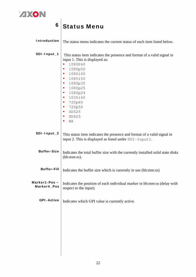
Introduction The status menu indicates the current status of each item listed below.
SDI-Input_1 This status item indicates the presence and format of a valid signal in input 1. This is displayed as: 1080P60 1080p50 1080i60 1080i50 1080p30 1080p25 1080p24 1035i60 720p60 720p50 SD525 SD625 NA
SDI-Input_2 This status item indicates the presence and format of a valid signal in
input 2. This is displayed as listed under SDI-Input1.
Buffer-Size Indicates the total buffer size with the currently installed solid state disks (hh:mm:ss).
Buffer-Fill Indicates the buffer size which is currently in use (hh:mm:ss)
Marker1-Pos ~
Marker4_Pos Indicates the position of each individual marker in hh:mm:ss (delay with respect to the input).
GPI-Active Indicates which GPI value is currently active.
23
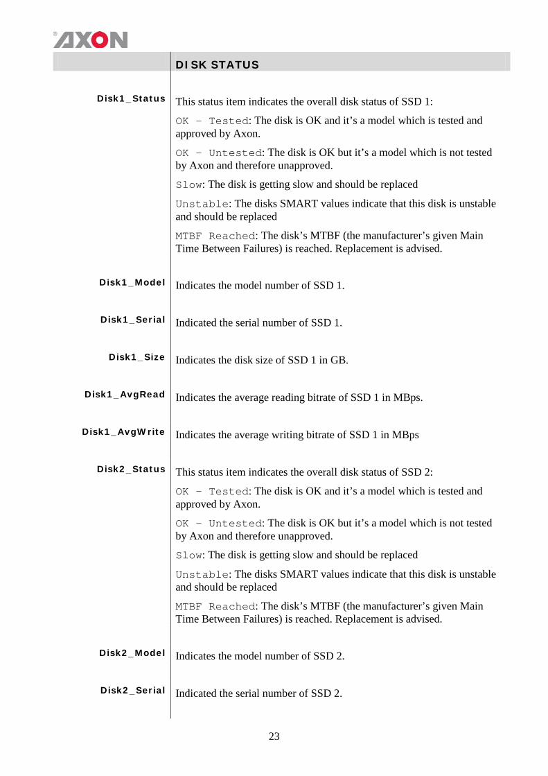
DISK STATUS
Disk1_Status This status item indicates the overall disk status of SSD 1:
OK - Tested: The disk is OK and it’s a model which is tested and approved by Axon.
OK - Untested: The disk is OK but it’s a model which is not tested by Axon and therefore unapproved.
Slow: The disk is getting slow and should be replaced
Unstable: The disks SMART values indicate that this disk is unstable and should be replaced
MTBF Reached: The disk’s MTBF (the manufacturer’s given Main Time Between Failures) is reached. Replacement is advised.
Disk1_Model Indicates the model number of SSD 1.
Disk1_Serial Indicated the serial number of SSD 1.
Disk1_Size Indicates the disk size of SSD 1 in GB.
Disk1_AvgRead Indicates the average reading bitrate of SSD 1 in MBps.
Disk1_AvgWrite Indicates the average writing bitrate of SSD 1 in MBps
Disk2_Status This status item indicates the overall disk status of SSD 2:
OK - Tested: The disk is OK and it’s a model which is tested and approved by Axon.
OK - Untested: The disk is OK but it’s a model which is not tested by Axon and therefore unapproved.
Slow: The disk is getting slow and should be replaced
Unstable: The disks SMART values indicate that this disk is unstable and should be replaced
MTBF Reached: The disk’s MTBF (the manufacturer’s given Main Time Between Failures) is reached. Replacement is advised.
Disk2_Model Indicates the model number of SSD 2.
Disk2_Serial Indicated the serial number of SSD 2.
24
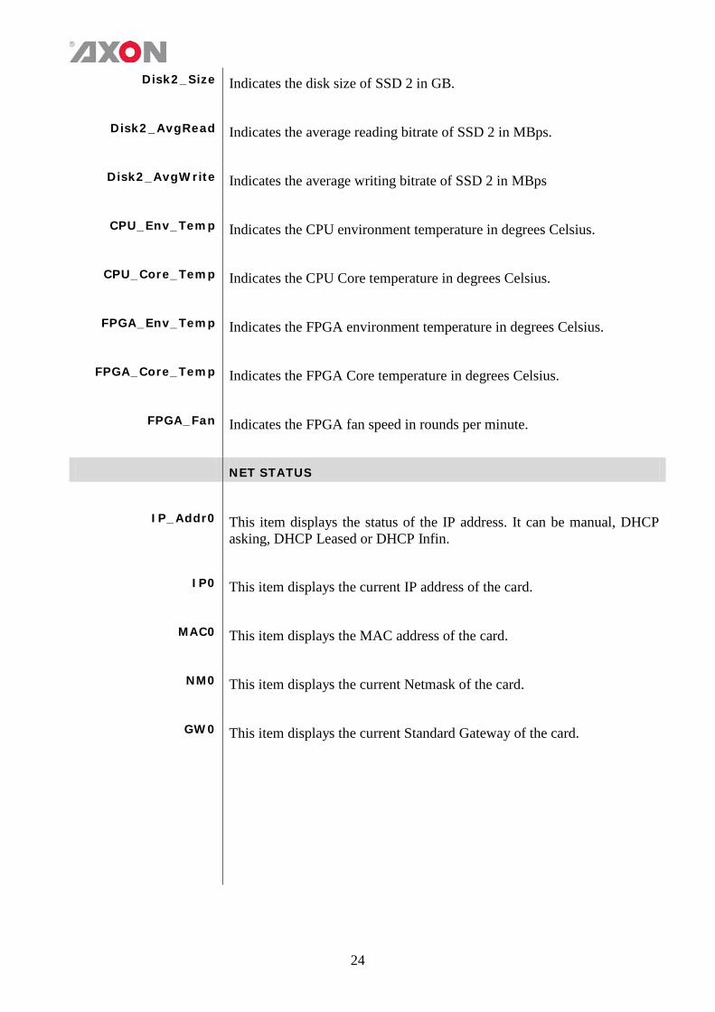
Disk2_Size Indicates the disk size of SSD 2 in GB.
Disk2_AvgRead Indicates the average reading bitrate of SSD 2 in MBps.
Disk2_AvgWrite Indicates the average writing bitrate of SSD 2 in MBps
CPU_Env_Temp Indicates the CPU environment temperature in degrees Celsius.
CPU_Core_Temp Indicates the CPU Core temperature in degrees Celsius.
FPGA_Env_Temp Indicates the FPGA environment temperature in degrees Celsius.
FPGA_Core_Temp Indicates the FPGA Core temperature in degrees Celsius.
FPGA_Fan Indicates the FPGA fan speed in rounds per minute. NET STATUS
IP_Addr0 This item displays the status of the IP address. It can be manual, DHCP asking, DHCP Leased or DHCP Infin.
IP0 This item displays the current IP address of the card.
MAC0 This item displays the MAC address of the card.
NM0 This item displays the current Netmask of the card.
GW0 This item displays the current Standard Gateway of the card.
25
7 Events Menu Introduction An event is a special message that is generated on the card asynchronously.
This means that it is not the response to a request to the card, but a spontaneous message.
What is the Goal of
an event? The goal of events is to inform the environment about a changing condition on the card. A message may be broadcast to mark the change in status. The message is volatile and cannot be retrieved from the system after it has been broadcast. There are several means by which the message can be filtered.
Events The events reported by the card are as follows;
Announcements Announcements is not an event. This item is only used for switching the
announcement of status changes on/off. 0=off, other =on
What information is available in an
event?
The message consists of the following items;
1) A message string to show what has happened in text, for example: “INP_LOSS”, “REF_LOSS”, “INP_RETURN”.
2) A tag that also shows what happens, but with a predefined number: e.g. 1 (= loss of input), 2 (= loss of reference), 129(= 1+128 = return of input). For a list of these predefined tags see the table on the next page.
3) A priority that marks the importance of an event. This value is defined by the user and can have any value between 1 and 255, or 0 when disabled.
4) A slot number of the source of this event.
The Message String The message string is defined in the card and is therefore fixed. It may be used in controlling software like Cortex to show the event.
The Tag The tag is also defined in the card. The tag has a fixed meaning. When
controlling or monitoring software should make decisions based on events, it is easier to use the tag instead of interpreting a string. The first implementation is the tag controlled switch in the GPI16.
In cases where the event marks a change to fault status (e.g. 1 for Loss of Input) the complement is marked by the tag increased by 128 (80hex) (e.g. 129 (81hex) for Return of Input).
26
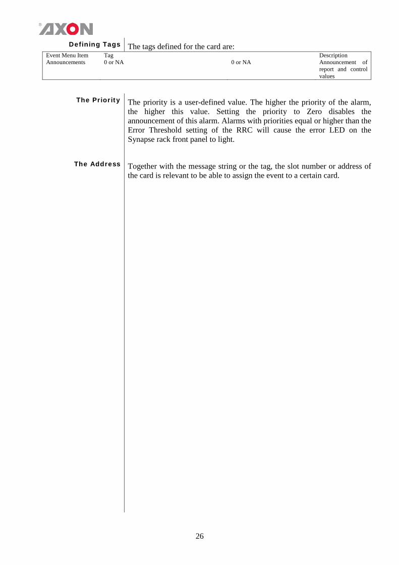
Defining Tags The tags defined for the card are: Event Menu Item Tag Description Announcements 0 or NA 0 or NA Announcement of
report and control values
The Priority The priority is a user-defined value. The higher the priority of the alarm, the higher this value. Setting the priority to Zero disables the announcement of this alarm. Alarms with priorities equal or higher than the Error Threshold setting of the RRC will cause the error LED on the Synapse rack front panel to light.
The Address Together with the message string or the tag, the slot number or address of
the card is relevant to be able to assign the event to a certain card.
8 LED Indication Introduction LEDS are located on the front of the card next to the card grip as
shown in the picture below. The LEDS give an indication of the status of the SLD100/200.
Error LED The error LED indicates an error if the internal logic of the card is not
configured correctly or has a hardware failure.
Input_1 LED This LED indicated the presence of a valid SDI video signal on input 1.
Input_2 LED This LED indicated the presence of a valid SDI video signal on input 2.
ANC Data LED Indicates the presence of embedded audio within the input signal.
Reference LED Indicated the presence of a valid reference signal on the selected
reference input connector (ref-1 or ref-2).
Data Error LED This LED indicates a CRC error.
Connection LED This LED illuminates after the card has initialized. The LED lights for 0.5 seconds every time a connection is made to the card.
Error LED The error LED indicates an error if the internal logic of the card is not
configured correctly or has a hardware failure.
9 Connector Panels
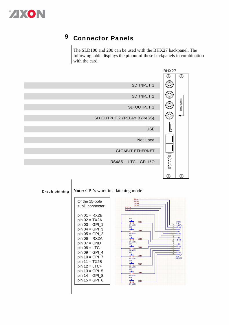
The SLD100 and 200 can be used with the BHX27 backpanel. The following table displays the pinout of these backpanels in combination with the card.
BHX27
rela
y by
pass
SD INPUT 1
SD INPUT 2
SD OUTPUT 1
SD OUTPUT 2 (RELAY BYPASS)
USB
Not used
GIGABIT ETHERNET
RS485 – LTC - GPI I/O
D-sub pinning
Note: GPI’s work in a latching mode
Of the 15-pole subD connector: pin 01 = RX2B pin 02 = TX2A pin 03 = GPI_1 pin 04 = GPI_3 pin 05 = GPI_2 pin 06 = RX2A pin 07 = GND pin 08 = LTC- pin 09 = GPI_4 pin 10 = GPI_7 pin 11 = TX2B pin 12 = LTC+ pin 13 = GPI_5 pin 14 = GPI_8 pin 15 = GPI_6
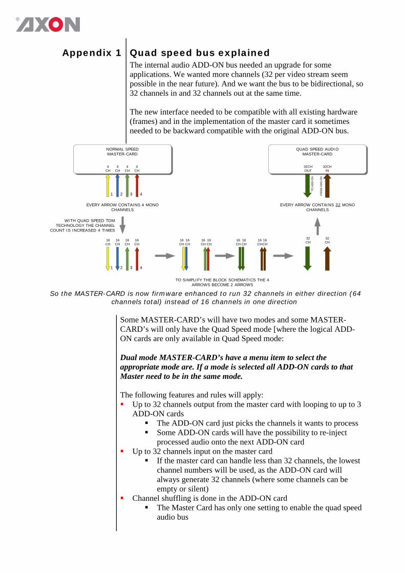
Appendix 1 Quad speed bus explained
The internal audio ADD-ON bus needed an upgrade for some applications. We wanted more channels (32 per video stream seem possible in the near future). And we want the bus to be bidirectional, so 32 channels in and 32 channels out at the same time. The new interface needed to be compatible with all existing hardware (frames) and in the implementation of the master card it sometimes needed to be backward compatible with the original ADD-ON bus.
QUAD SPEED AUDIO
MASTER-CARDNORMAL SPEEDMASTER-CARD
1 2 3 4
TO A
DD
-ON
FRO
M A
DD
-ON
EVERY ARROW CONTAINS 4 MONO CHANNELS
EVERY ARROW CONTAINS 32 MONO CHANNELS
32CHOUT
32CHIN
1 2 3 4
4CH
4CH
4CH
4CH
16CH
16CH
16CH
16CH
16CH
16CH
16CH
16CH
32CH
32CH
WITH QUAD SPEED TDM TECHNOLOGY THE CHANNEL
COUNT IS INCREASED 4 TIMES
TO SIMPLIFY THE BLOCK SCHEMATICS THE 4 ARROWS BECOME 2 ARROWS
16CH
16CH
16CH
16CH
So the MASTER-CARD is now firmware enhanced to run 32 channels in either direction (64 channels total) instead of 16 channels in one direction
Some MASTER-CARD’s will have two modes and some MASTER-
CARD’s will only have the Quad Speed mode [where the logical ADD-ON cards are only available in Quad Speed mode: Dual mode MASTER-CARD’s have a menu item to select the appropriate mode are. If a mode is selected all ADD-ON cards to that Master need to be in the same mode. The following features and rules will apply: Up to 32 channels output from the master card with looping to up to 3
ADD-ON cards The ADD-ON card just picks the channels it wants to process Some ADD-ON cards will have the possibility to re-inject
processed audio onto the next ADD-ON card Up to 32 channels input on the master card
If the master card can handle less than 32 channels, the lowest channel numbers will be used, as the ADD-ON card will always generate 32 channels (where some channels can be empty or silent)
Channel shuffling is done in the ADD-ON card The Master Card has only one setting to enable the quad speed
audio bus

Every Quad-Speed ADD-ON card takes 32 channels from the ‘right hand ADD-ON card’ and adds (or overwrites) the local processed channels. This can be done for any of the channels that are processed in
the ADD-ON card Some Master Cards are switchable between normal and quad-speed
bus Channel designations on the block schematics:
Channel 1-32 (or less) are injected into the dark green large arrow from Master Card to ADD-ON card and looped on to the next ADD-ON card via the dark green arrow
The ADD-ON card injects up to 32 channels into the brown large arrow
An ADD-ON card will also actively loop extra processed channels into the next ADD-ON card, and finally into the Master Card
The cross looping of the original design is now a straight loop The quad speed bus can also work in one direction
You can use a Quad Speed audio bus to de-embed audio from the master and present on the ADD-ON card as AES/EBU, Bitstream (like Dolby) or analog audio
If applicable the ADD-ON card can also be used as in injection point of physical audio streams
QUAD SPEED AUDIO
MASTER-CARDNORMAL SPEEDAD-ON CARD
EVERY ARROW CONTAINS 4 MONO CHANNELS
EVERY ARROW CONTAINS 32 MONO CHANNELS
1 2 3 4
32CHIN
32CHOUT
32CHIN
FRO
M M
ASTE
R
TO M
ASTE
R
TO N
EXT
ADD
-ON
FRO
M N
EXT
ADD
-ON
32CHOUT
The ADD-ON cards also provide a looping function from one ADD-ON to the next. This is
however a more intelligent looping with optional re-insertion and muxing of signals.
Cascading of Quad Speed cards works identical to normal add-on cards. Every connection in the example below transports 16 mono audio channels (= 32 channels per color). It shows the inter slot connections ‘in quad Speed mode’ as part of the frame bus PCB.
SLOT 01 SLOT 02 SLOT 03 SLOT 04 SLOT 05 SLOT 06 SLOT 16 SLOT 17 SLOT 18
SYNAPSE BUS
SYNAPSE BUS
SYNAPSE BUS
SYNAPSE BUS
SYNAPSE BUS
SYNAPSE BUS
SYNAPSE BUS
The system makes use of the same passive copper traces on the internal
bus PCB as normal add-on bus cards.
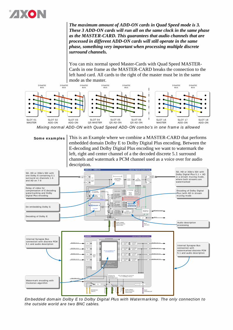
The maximum amount of ADD-ON cards in Quad Speed mode is 3. These 3 ADD-ON cards will run all on the same clock in the same phase as the MASTER-CARD. This guarantees that audio channels that are processed in different ADD-ON cards will still operate in the same phase, something very important when processing multiple discrete surround channels.
You can mix normal speed Master-Cards with Quad Speed MASTER-Cards in one frame as the MASTER-CARD breaks the connection to the left hand card. All cards to the right of the master must be in the same mode as the master.
SLOT 01MASTER
SLOT 02ADD-ON
SLOT 03ADD-ON
SLOT 16MASTER
SLOT 17ADD-ON
SLOT 18ADD-ON
SYNAPSE BUS
SYNAPSE BUS
SYNAPSE BUS
SYNAPSE BUS
SYNAPSE BUS
SYNAPSE BUS
SYNAPSE BUS
SLOT 04QS MASTER
SLOT 05QS AD-ON
SLOT 06QS AD-ON
Mixing normal ADD-ON with Quad Speed ADD-ON combo’s in one frame is allowed
Some examples This is an Example where we combine a MASTER-CARD that performs embedded domain Dolby E to Dolby Digital Plus encoding. Between the E-decoding and Dolby Digital Plus encoding we want to watermark the left, right and center channel of a the decoded discrete 5.1 surround channels and watermark a PCM channel used as a voice over for audio description.
GED130 - HED130 [Quad-Speed audio bus]
Rack controller
µP GPI/O
METADATA
2Ch
Dolby E
4 Ch4 Ch4 Ch
4 Ch
METADATA IN/OUT
QUAD SPEED MULTIPLEXINGAUDIO BUS
32CH OUT 32CH IN
TO A
DD
-ON
FRO
M A
DD
-ON
Eq
Eq
16 CHANNEL
EMBEDDER
2x1
AUTOMUX
ADJUSTABLEOFFSET DELAY
0-500ms
S2020INSERT
16 Ch16 CHANNEL DE-EMBEDDER
S2020READER
METADATAHANDLING
16 CHANNEL
DELAYGAIN
PHASE
50X16 MUX
16 DE-EMBED8 DECODED E16 QUAD SPEED4 DOLBY D(+)2 AD
8 Ch
METADATA
METADATA
TDM MUX/DE-MUX16 Ch
DECODER
2Ch2Ch2Ch
Dolby Digital (plus) 1-2-3-4
42X4 MUX 2 AD16 DE-EMBED8 DECODED E16 QUAD SPEED
PCM
AUDIO DESCRIPTION PROCESSING
40X4 MUX 16 DE-EMBED8 DECODED E
16 QUAD SPEED
Internal Synapse Bus connection with watermarked discrete PCM 5.1 and audio description
Encoding of Dolby Digital Plus (with AD in stream muxing mode
SD, HD or 3Gb/s SDI with one Dolby E containing 5.1 surround on channels 1-6 and AD on 7-8
SD, HD or 3Gb/s SDI with Dolby Digital Plus 5.1 + AD in a stream muxing mode, where both streams are watermarked
Audio description processing
DAW88 [QUAD SPEED AUDIO BUS]
RACK CONTROLLER
AES/EBU OUT 1/2
µP
AES/EBU IN 1/2 SRC
AES/EBU IN 3/4
AES/EBU IN 5/6
AES/EBU IN 7/8
AES/EBU OUT 3/4
AES/EBU OUT 5/6
AES/EBU OUT 7/8
32 CHANNEL
SRC
SRC
SRC
32CHIN
QUAD SPEED MULTIPLEXINGAUDIO BUS
32CHOUT
32CHIN
32CHOUT
FRO
M M
ASTE
R
TO M
ASTE
R
TO N
EXT
ADD
-ON
FRO
M N
EXT
ADD
-ON
2 CHANNELGAIN
ADD-ON EMBED MULTIPLEXING4 X 2-CHANNELS INTO 32
2 CHANNELDELAY
HIGH POWER DSP SUB MODULE
REAL TIME CLOCK WITH BATTERY BACK-UP
40x8INPUTMUX
2 CHANNELDELAY
2 CHANNELDELAY
2 CHANNELDELAY
TIME CODE (LTC) COMP
GPI (3 INPUTS)
REFERENCEINPUTS
1 2
PLL
UP TO 8 CHANNELS OF WATERMARKING
MUX
OPTIONAL RE-INSERTING OF PROCESSED AUDIO
ACTIVE BYPASS
2 CHANNELGAIN
2 CHANNELGAIN
2 CHANNELGAIN
Watermark encoding with Civolution algorithm
Internal Synapse Bus connection with discrete PCM 5.1 and audio description
Delay of video for compensation of E decoding watermarking and Dolby Digital Plus encoding
De-embedding Dolby E
Decoding of Dolby E
Embedded domain Dolby E to Dolby Digital Plus with Watermarking. The only connection to the outside world are two BNC cables.
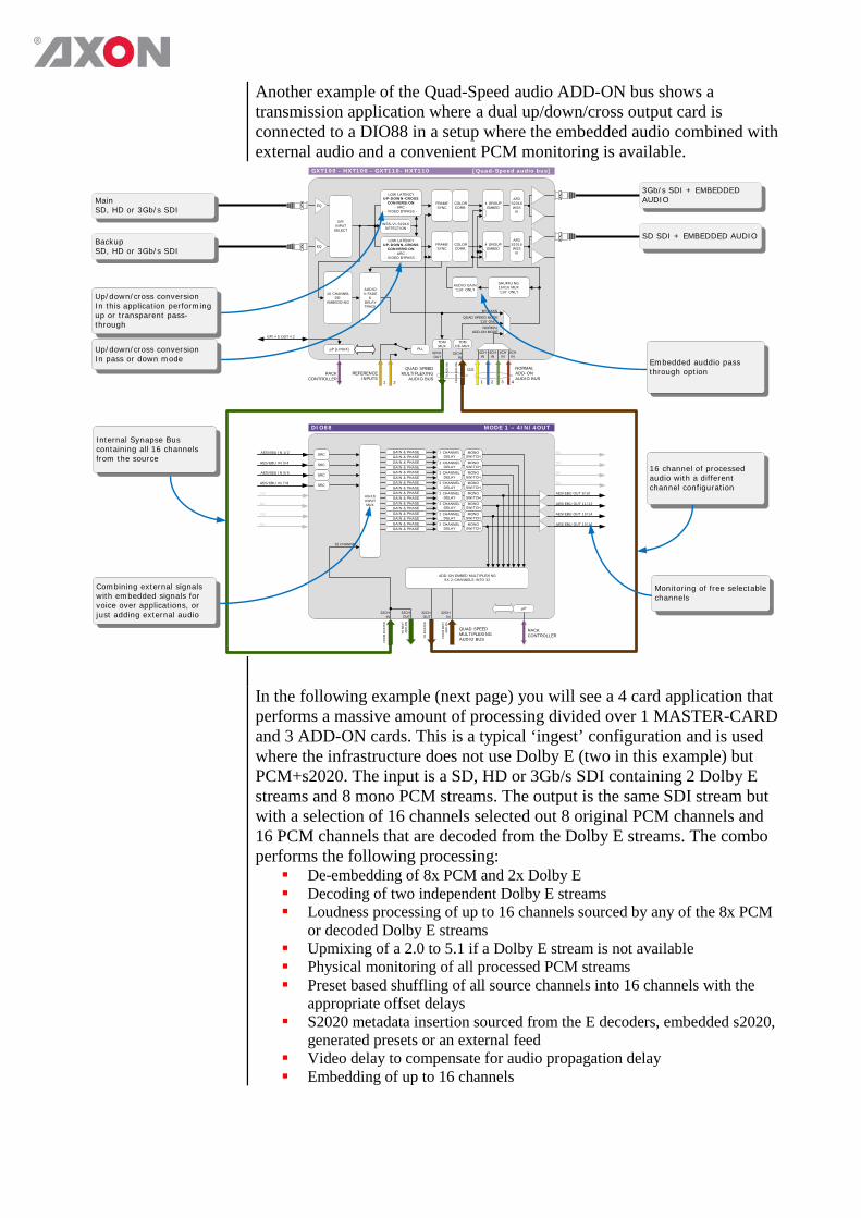
Another example of the Quad-Speed audio ADD-ON bus shows a transmission application where a dual up/down/cross output card is connected to a DIO88 in a setup where the embedded audio combined with external audio and a convenient PCM monitoring is available.
DIO88 MODE 1 – 4IN/4OUT
RACK CONTROLLER
AES/EBU OUT 9/10
µP
AES/EBU IN 1/2 SRC
AES/EBU IN 3/4
AES/EBU IN 5/6
AES/EBU IN 7/8
AES/EBU OUT 11/12
AES/EBU OUT 13/14
AES/EBU OUT 15/16
32 CHANNEL
GAIN & PHASE
40x16INPUTMUX
SRC
SRC
SRC
32CHIN
QUAD SPEED MULTIPLEXINGAUDIO BUS
32CHOUT
32CHIN
32CHOUT
FRO
M M
AS
TER
TO M
AS
TER
TO N
EX
T A
DD
-ON
FRO
M N
EX
TA
DD
-ON
GAIN & PHASEGAIN & PHASEGAIN & PHASEGAIN & PHASEGAIN & PHASEGAIN & PHASEGAIN & PHASEGAIN & PHASEGAIN & PHASEGAIN & PHASEGAIN & PHASEGAIN & PHASEGAIN & PHASEGAIN & PHASEGAIN & PHASE
2 CHANNELDELAY
2 CHANNELDELAY
2 CHANNELDELAY
2 CHANNELDELAY
ADD-ON EMBED MULTIPLEXING8X 2-CHANNELS INTO 32
NC
NC
NC
NC
NC
NC
NC
NC
MONOSWITCHMONO
SWITCHMONO
SWITCHMONO
SWITCH2 CHANNEL
DELAY2 CHANNEL
DELAY2 CHANNEL
DELAY2 CHANNEL
DELAY
MONOSWITCHMONO
SWITCHMONO
SWITCHMONO
SWITCH
GXT100 - HXT100 - GXT110- HXT110 [Quad-Speed audio bus]
LOW LATENCYUP-DOWN-CROSS
CONVERSION- ARC -
- VIDEO BYPASS -
FRAMESYNC
COLOR CORR.
LOW LATENCYUP-DOWN-CROSS
CONVERSION- ARC -
- VIDEO BYPASS -
WSS-VI-S2016DETECTION
4 GROUPEMBED
FRAMESYNC
COLOR CORR.
4 GROUPEMBED
EQ
EQ
AFDS2016WSSVI
AFDS2016WSSVI
REFERENCEINPUTS
1 2
PLL
RACK CONTROLLER
GPI #5 OUT #2
µP [LINUX]
16 CHANNEL DE-
EMBEDDING
GPIINPUT SELECT
SHUFFLING16X16 MUX‘110’ ONLY
AUDIO GAIN‘110’ ONLYAUDIO
V-FADE&
DELAYTRACK
QUAD SPEED MULTIPLEXING
AUDIO BUS
32CHOUT
32CHIN
1 2 3 4
4CHIN
4CHIN
4CHIN
4CHIN
TDMMUX
TO A
DD
-ON
FRO
M A
DD
-ON
OR NORMALADD-ONAUDIO BUS
QUAD SPEED MODE ‘110’ ONLY
NORMAL ADD-ON MODE
BY-PASS
TDMDE-MUX
16 channel of processed audio with a different channel configuration
MainSD, HD or 3Gb/s SDI
Combining external signals with embedded signals for voice over applications, or just adding external audio
Internal Synapse Bus containing all 16 channels from the source
Up/down/cross conversionIn this application performing up or transparent pass-through
Up/down/cross conversion In pass or down mode
3Gb/s SDI + EMBEDDED AUDIO
BackupSD, HD or 3Gb/s SDI
SD SDI + EMBEDDED AUDIO
Embedded auddio pass through option
Monitoring of free selectable channels
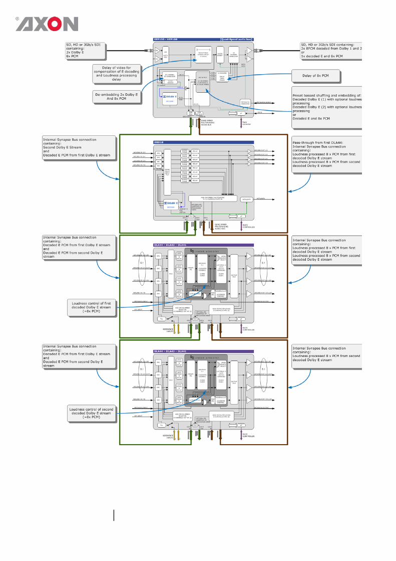
In the following example (next page) you will see a 4 card application that performs a massive amount of processing divided over 1 MASTER-CARD and 3 ADD-ON cards. This is a typical ‘ingest’ configuration and is used where the infrastructure does not use Dolby E (two in this example) but PCM+s2020. The input is a SD, HD or 3Gb/s SDI containing 2 Dolby E streams and 8 mono PCM streams. The output is the same SDI stream but with a selection of 16 channels selected out 8 original PCM channels and 16 PCM channels that are decoded from the Dolby E streams. The combo performs the following processing: De-embedding of 8x PCM and 2x Dolby E Decoding of two independent Dolby E streams Loudness processing of up to 16 channels sourced by any of the 8x PCM
or decoded Dolby E streams Upmixing of a 2.0 to 5.1 if a Dolby E stream is not available Physical monitoring of all processed PCM streams Preset based shuffling of all source channels into 16 channels with the
appropriate offset delays S2020 metadata insertion sourced from the E decoders, embedded s2020,
generated presets or an external feed Video delay to compensate for audio propagation delay Embedding of up to 16 channels

Appendix 2 Uploading logos using cortex
Introduction The most common and easy way to upload logo or fonts is to use Cortex,
which contains a GUI view to upload logos and fonts. Cortex is downloadable on our website free of charge.
NOTE For uploading logo’s the bottom Ethernet connection must be used!
Uploading files Configure the IP address of the SLD network interface using Cortex 1.01
or higher. Use DHCP or fixed IP address on your network and also configure the subnet mask. Note the SLD may be on the same network as the rack controller. The IP addresses shown here are just examples, replace these addresses with others if needed. See picture below.
Select the “upload preset” from the drop down list, and press the Upload button.
Select a PNG file and click the Open button. The logo files must be of the PNG type, RGB plus alpha channel. Interlaced PNG files with “Adam 7” coding are not supported. TGA files are not supported.. Animated OXA files are not supported. Other file formats are not supported and recognized. This is by design.

The Upload will start. Now you only need to set the Active-Preset.
You can use the Edit-Preset to change the position, fade and animation
playback.
Appendix 3 Uploading logos using WebDav or FTP.
Introduction The most common and easy way to upload logo or fonts is to use Cortex, which contains a GUI view to upload logos and fonts. If you are not using Cortex, you can still upload logos and fonts. To upload logo and/or font files to the SLD without using Cortex, attach the card using its Ethernet port to a computer that support WebDAV (Web Folders).
WebDAV WebDAV is an abbreviation for "Web-based Distributed Authoring and
Versioning" (published as an open standard under RFC 2518). WebDAV is a set of extensions to the HTTP protocol which allows users to collaboratively edit and manage files on a web server. This is achieved by making use of a WebDAV compatible client / application. For example, it is possible to use recent versions of Microsoft’s Internet Explorer (versions 6.0 and higher). Using a WebDAV compatible client, the user connects to the server and is able to browse and manage files in a similar way as with a network share or an FTP server. In other words, what this protocol does is that it makes it possible to browse, create, remove, upload, download, rename, etc. files and directories on a web server. One of the most important advantages of this technology is that it uses port 80 for network traffic. This means that if you are able to surf the site from your workstation, you can also use WebDAV to administer it. It does not require firewall reconfiguration.
FTP FTP (File Transport Protocol) is a very commonly used network protocol used to exchange and manipulate files over a TCP computer network. This protocol is also compatible with the SLD cards. An FTP client may connect to an FTP server (in this case the logo/text inserter) to manipulate files on that server.
Uploading files
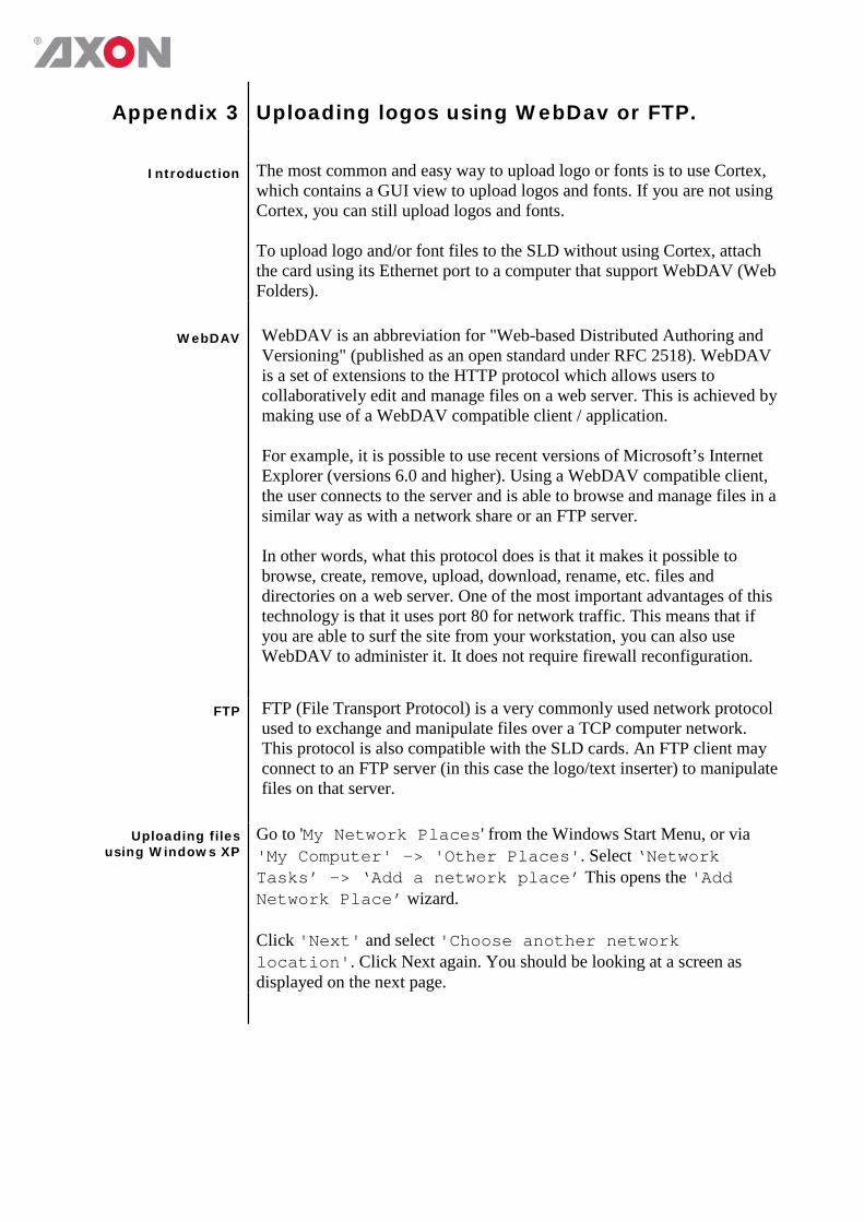
using Windows XP Go to 'My Network Places' from the Windows Start Menu, or via 'My Computer' -> 'Other Places'. Select ‘Network Tasks’ -> ‘Add a network place’ This opens the 'Add Network Place’ wizard. Click 'Next' and select 'Choose another network location'. Click Next again. You should be looking at a screen as displayed on the next page.
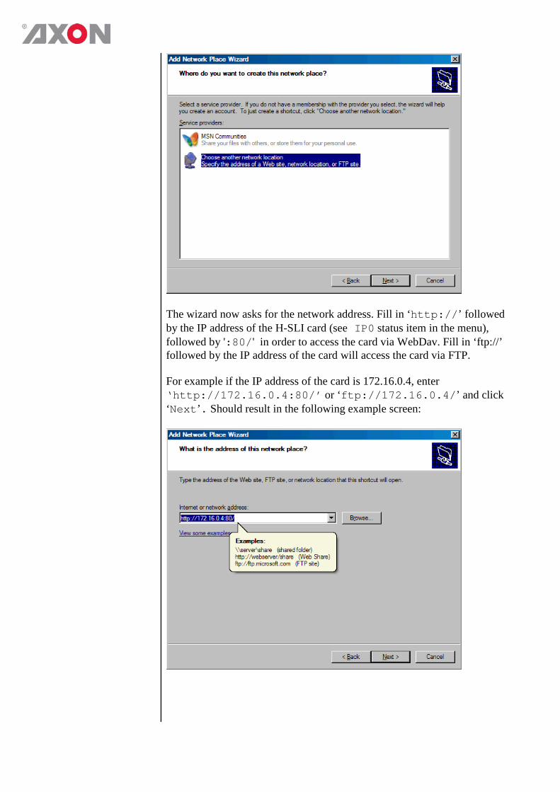
The wizard now asks for the network address. Fill in ‘http://’ followed by the IP address of the H-SLI card (see IP0 status item in the menu), followed by ':80/' in order to access the card via WebDav. Fill in ‘ftp://’ followed by the IP address of the card will access the card via FTP. For example if the IP address of the card is 172.16.0.4, enter ‘http://172.16.0.4:80/’ or ‘ftp://172.16.0.4/’ and click ‘Next’. Should result in the following example screen:
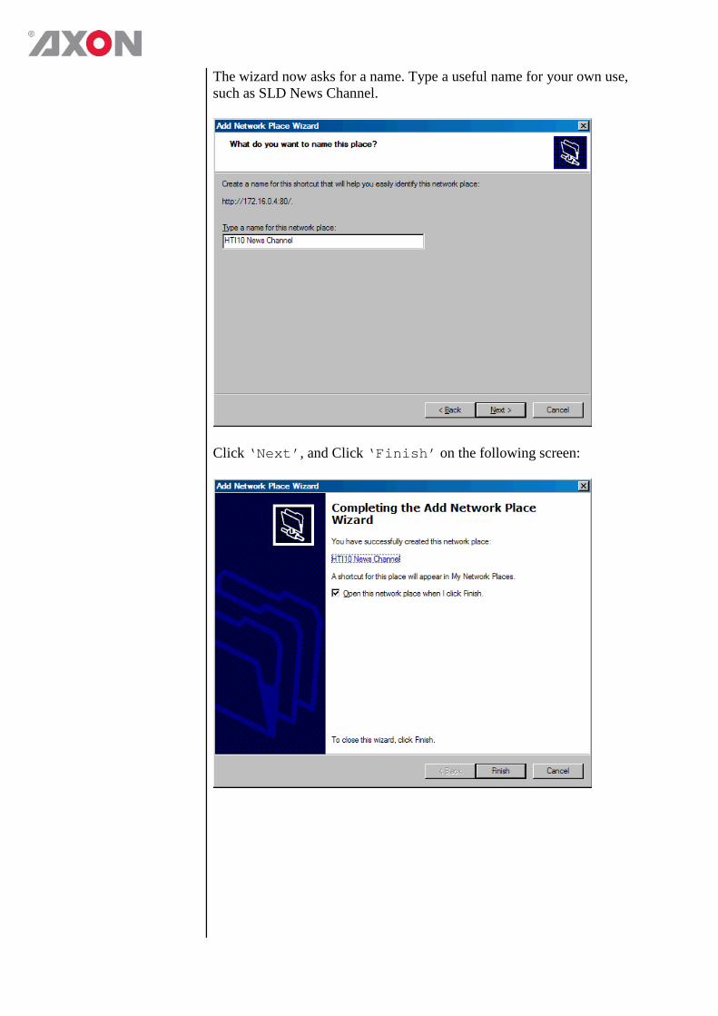
The wizard now asks for a name. Type a useful name for your own use, such as SLD News Channel.
Click ‘Next’, and Click ‘Finish’ on the following screen:
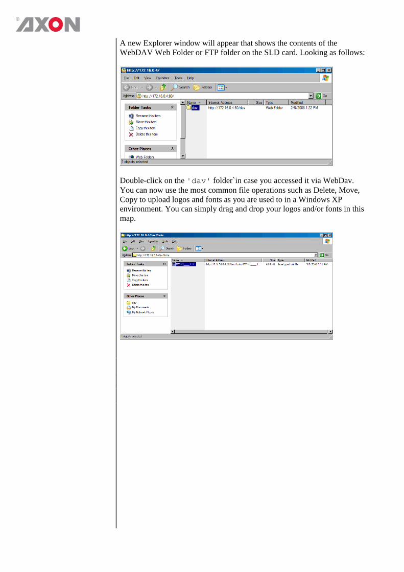
A new Explorer window will appear that shows the contents of the WebDAV Web Folder or FTP folder on the SLD card. Looking as follows:
Double-click on the 'dav' folder`in case you accessed it via WebDav. You can now use the most common file operations such as Delete, Move, Copy to upload logos and fonts as you are used to in a Windows XP environment. You can simply drag and drop your logos and/or fonts in this map.
Appendix 4 Reprogramming SLDxxx modules Before you start
Functionality explanation
A Synapse card’s functionality is decided by 2 parts: the hardware platform and the software (a.k.a. firmware) that resides on the hardware platform. Changing the firmware of the cards means changing the way the card functions. To keep improving quality and to answer our customer’s demands, Axon sometimes releases new software revisions of Synapse cards. These software revisions are formatted in 1 file per revision, with a .spf extension. Customers can download these .spf files from our website, or receive them via e-mail from our support so they can upgrade or reprogram their own cards.
Choosing .spf files Not all .spf files are compatible with all hardware platforms. To know
for certain that you are choosing a compatible .spf file you have to know the hardware revision of your card. This revision number can be found in the menu of the card via the control panel on the frames (select card, select ‘about’, check HW number) or via Cortex (Axon’s control software) (select frame, select card, select ‘Identity’, check ‘hardware rev’). Knowing the hardware revision number, you can go to our website (www.axon.tv) and go to our download firmware section. Here you select the card you wish to upgrade. You will see a list of available firmware upgrades of this particular card. The firmware files that are compatible with your card should display your card’s hardware revision number in table next to “Hardware versions”. If this is not the case you will not be able to upgrade your card with that file.
Requirements For reprogramming or upgrading cards, you need the Cortex program
installed on a PC or laptop which is connected to the same network to which the card is connected also. You can download the program free of charge from our website. For this this card you need to use Cortex version v1.091 or later. Updating the card must be done locally (direct connection) through the Ethernet of the backplane. The bottom Ethernet connection must be used.
Using Cortex help
files This manual describes how to upgrade cards using Cortex. When you are using Cortex and require card further instructions, please refer to the Cortex help files (select ‘Card’ in the menu > select ‘Upload Firmware’ (the firmware uploading window will open) > press F1).
Precautions
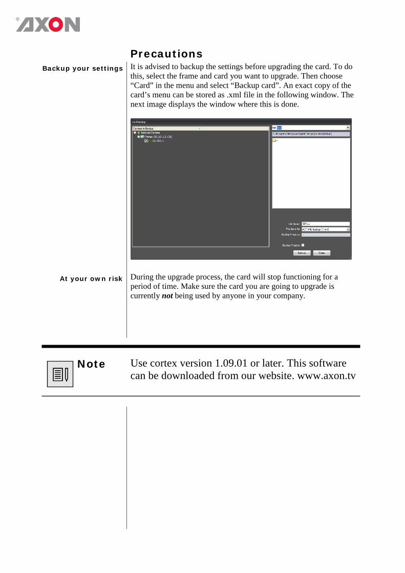
Backup your settings It is advised to backup the settings before upgrading the card. To do this, select the frame and card you want to upgrade. Then choose “Card” in the menu and select “Backup card”. An exact copy of the card’s menu can be stored as .xml file in the following window. The next image displays the window where this is done.
At your own risk During the upgrade process, the card will stop functioning for a period of time. Make sure the card you are going to upgrade is currently not being used by anyone in your company.
Note Use cortex version 1.09.01 or later. This software can be downloaded from our website. www.axon.tv
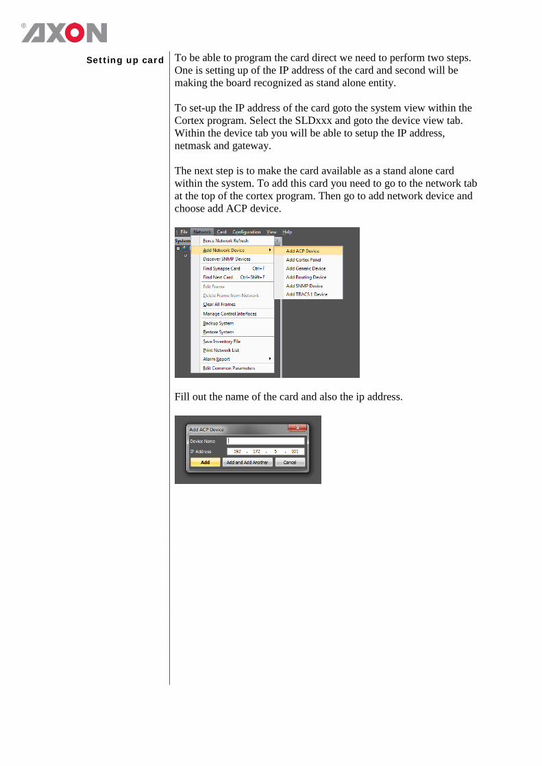
Setting up card To be able to program the card direct we need to perform two steps. One is setting up of the IP address of the card and second will be making the board recognized as stand alone entity. To set-up the IP address of the card goto the system view within the Cortex program. Select the SLDxxx and goto the device view tab. Within the device tab you will be able to setup the IP address, netmask and gateway. The next step is to make the card available as a stand alone card within the system. To add this card you need to go to the network tab at the top of the cortex program. Then go to add network device and choose add ACP device.
Fill out the name of the card and also the ip address.
Upload firmware
Opening the upload window
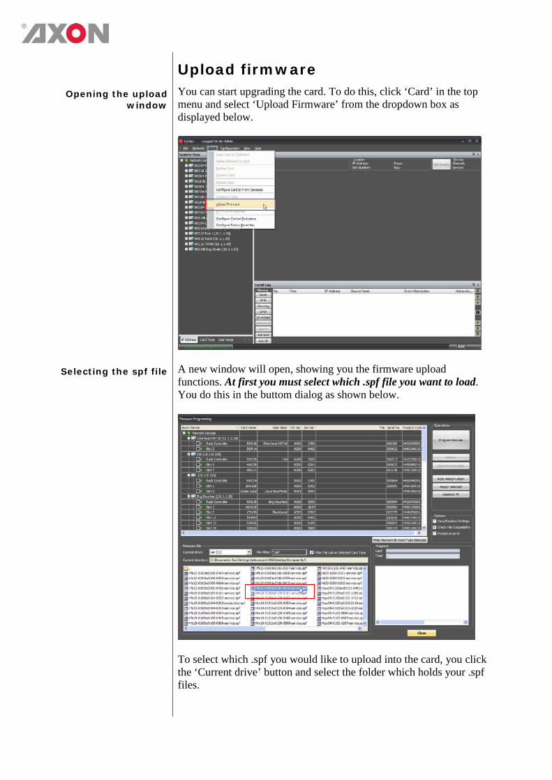
You can start upgrading the card. To do this, click ‘Card’ in the top menu and select ‘Upload Firmware’ from the dropdown box as displayed below.
Selecting the spf file A new window will open, showing you the firmware upload functions. At first you must select which .spf file you want to load. You do this in the buttom dialog as shown below.
To select which .spf you would like to upload into the card, you click the ‘Current drive’ button and select the folder which holds your .spf files.
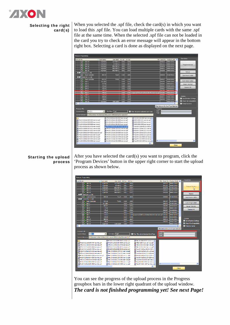
Selecting the right card(s)
When you selected the .spf file, check the card(s) in which you want to load this .spf file. You can load multiple cards with the same .spf file at the same time. When the selected .spf file can not be loaded in the card you try to check an error message will appear in the bottom right box. Selecting a card is done as displayed on the next page.
Starting the upload process
After you have selected the card(s) you want to program, click the ‘Program Devices’ button in the upper right corner to start the upload process as shown below. You can see the progress of the upload process in the Progress groupbox bars in the lower right quadrant of the upload window. The card is not finished programming yet! See next Page!

Note CARD IS FINISHED PROGRAMMING WHEN THE LED’S STOP BLINKING. THIS WILL TAKE LONGER THAN THE FILE TRANSFER TO THE CARD
Ready programming When the file has succesfully been uploaded, the progress bar will be at 100% and in the box below it says ‘Ready programming card’. To make sure the card is working properly, we advise to reset the card manually by pulling it out and putting it back into the frame. When the card is recognized with the right cardname, the firmware upgrade has been succesfull.
Update Cortex form
(CLF file) To make sure Cortex is up to date with your card’s new firmware, please make sure to update the card’s Cortex form so all new functions can be used. To do this simply copy the .clf, which is usually included with your firmware download, into the ‘[installation folder of Cortex]\Forms\Device’ folder. With a default installation this should be: C:\program files\Axon Digital Design\Cortex\Forms\Device\ Make sure to reboot Cortex after you copied the .clf file to this folder.
Testing When all previous instructions have been completed the card should
be functioning properly. We advise however to test the card’s functionallity before you are going to put it into real on-air use.
This product contains open-source software This product contains open-source software licensed under the GNU Public License (GPL). A copy of the GNU Public License is included below. Under this license you are eligible to receive a copy of the source code of this software including any changes. Axon Digital Design shall provide the source code on request either through physical distribution or electronic communication. For physical distribution you may be charged a fee that covers distribution costs. This offer is valid up to three years after date of purchase. Please direct your request to the support department of Axon Digital Design. Axon Digital Design supports open-source software by participating in the development of open-source projects or submitting improvements to these projects. For more information see http://opensource.axon.tv/
GNU Public License version 2 TERMS AND CONDITIONS FOR COPYING, DISTRIBUTION AND MODIFICATION 0. This License applies to any program or other work which contains a notice placed by the copyright holder saying it may be distributed under the terms of this General Public License. The “Program”, below, refers to any such program or work, and a “work based on the Program” means either the Program or any derivative work under copyright law: that is to say, a work containing the Program or a portion of it, either verbatim or with modifi cations and/or translated into another language. (Hereinafter, translation is included without limitation in the term “modifi cation”.) Each licensee is addressed as “you”. Activities other than copying, distribution and modifi cation are not covered by this License; they are outside its scope. The act of running the Program is not restricted, and the output from the Program is covered only if its contents constitute a work based on the Program (independent of having been made by running the Program). Whether that is true depends on what the Program does. 1. You may copy and distribute verbatim copies of the Program’s source code as you receive it, in any medium, provided that you conspicuously and appropriately publish on each copy an appropriate copyright notice and disclaimer of warranty; keep intact all the notices that refer to this License and to the absence of any warranty; and give any other recipients of the Program a copy of this License along with the Program. You may charge a fee for the physical act of transferring a copy, and you may at your option offer warranty protection in exchange for a fee. 2. You may modify your copy or copies of the Program or any portion of it, thus forming a work based on the Program, and copy and distribute such modifications or work under the terms of Section 1 above, provided that you also meet all of these conditions:
a) You must cause the modified files to carry prominent notices stating that you changed the fi les and the date of any change. b) You must cause any work that you distribute or publish, that in whole or in part contains or is derived from the Program or any
part thereof, to be licensed as a whole at no charge to all third parties under the terms of this License. c) If the modified program normally reads commands interactively when run, you must cause it, when started running for such
interactive use in the most ordinary way, to print or display an announcement including an appropriate copyright notice and a notice that there is no warranty (or else, saying that you provide a warranty) and that users may redistribute the program under these conditions, and telling the user how to view a copy of this License. (Exception: if the Program itself is interactive but does not normally print such an announcement, your work based on the Program is not required to print an announcement.)
These requirements apply to the modified work as a whole. If identifiable sections of that work are not derived from the Program, and can be reasonably considered independent and separate works in themselves, then this License, and its terms, do not apply to those sections when you distribute them as separate works. But when you distribute the same sections as part of a whole which is a work based on the Program, the distribution of the whole must be on the terms of this License, whose permissions for other licensees extend to the entire whole, and thus to each and every part regardless of who wrote it. Thus, it is not the intent of this section to claim rights or contest your rights to work written entirely by you; rather, the intent is to exercise the right to control the distribution of derivative or collective works based on the Program. In addition, mere aggregation of another work not based on the Program with the Program (or with a work based on the Program) on a volume of a storage or distribution medium does not bring the other work under the scope of this License. 3. You may copy and distribute the Program (or a work based on it, under Section 2) in object code or executable form under the terms of Sections 1 and 2 above provided that you also do one of the following:
a) Accompany it with the complete corresponding machine-readable source code, which must be distributed under the terms of Sections 1 and 2 above on a medium customarily used for software interchange; or,
b) Accompany it with a written offer, valid for at least three years, to give any third party, for a charge no more than your cost of physically performing source distribution, a complete machine-readable copy of the corresponding source code, to be distributed under the terms of Sections 1 and 2 above on a medium customarily used for software interchange; or,

c) Accompany it with the information you received as to the offer to distribute corresponding source code. (This alternative is allowed only for noncommercial distribution and only if you received the program in objects code or executable form with such an offer, in accord with Subsection b above.)
The source code for a work means the preferred form of the work for making modifi cations to it. For an executable work, complete source code means all the source code for all modules it contains, plus any associated interface defi nition fi les, plus the scripts used to control compilation and installation of the executable. However, as a special exception, the source code distributed need not include anything that is normally distributed (in either source or binary form) with the major components (compiler, kernel, and so on) of the operating system on which the executable runs, unless that component itself accompanies the executable. If distribution of executable or object code is made by offering access to copy from a designated place, then offering equivalent access to copy the source code from the same place counts as distribution of the source code, even though third parties are not compelled to copy the source along with the object code. 4. You may not copy, modify, sublicense, or distribute the Program except as expressly provided under this License. Any attempt otherwise to copy, modify, sublicense or distribute the Program is void, and will automatically terminate your rights under this License. However, parties who have received copies, or rights, from you under this License will not have their licenses terminated so long as such parties remain in full compliance. 5. You are not required to accept this License, since you have not signed it. However, nothing else grants you permission to modify or distribute the Program or its derivative works. These actions are prohibited by law if you do not accept this License. Therefore, by modifying or distributing the Program (or any work based on the Program), you indicate your acceptance of this License to do so, and all its terms and conditions for copying, distributing or modifying the Program or works based on it. 6. Each time you redistribute the Program (or any work based on the Program), the recipient automatically receives a license from the original licensor to copy, distribute or modify the Program subject to these terms and conditions. You may not impose any further restrictions on the recipients’ exercise of the rights granted herein. You are not responsible for enforcing compliance by third parties to this License. 7. If, as a consequence of a court judgment or allegation of patent infringement or for any other reason (not limited to patent issues), conditions are imposed on you (whether by court order, agreement or otherwise) that contradict the conditions of this License, they do not excuse you from the conditions of this License. If you cannot distribute so as to satisfy simultaneously your obligations under this License and any other pertinent obligations, then as a consequence you may not distribute the Program at all. For example, if a patent license would not permit royalty-free redistribution of the Program by all those who receive copies directly or indirectly through you, then the only way you could satisfy both it and this License would be to refrain entirely from distribution of the Program. If any portion of this section is held invalid or unenforceable under any particular circumstance, the balance of the section is intended to apply and the section as a whole is intended to apply in other circumstances. It is not the purpose of this section to induce you to infringe any patents or other property right claims or to contest validity of any such claims; this section has the sole purpose of protecting the integrity of the free software distribution system, which is implemented by public license practices. Many people have made generous contributions to the wide range of software distributed through that system in reliance on consistent application of that system; it is up to the author/donor to decide if he or she is willing to distribute software through any other system and a licensee cannot impose that choice. This section is intended to make thoroughly clear what is believed to be a consequence of the rest of this License. 8. If the distribution and/or use of the Program is restricted in certain countries either by patents or by copyrighted interfaces, the original copyright holder who places the Program under this License may add an explicit geographical distribution limitation excluding those countries, so that distribution is permitted only in or among countries not thus excluded. In such case, this License incorporates the limitation as if written in the body of this License. 9. The Free Software Foundation may publish revised and/or new versions of the General Public License from time to time. Such new versions will be similar in spirit to the present version, but may differ in detail to address new problems or concerns. Each version is given a distinguishing version number. If the Program specifies a version number of this License which applies to it and “any later version”, you have the option of following the terms and conditions either of that version or of any later version published by the Free Software Foundation. If the Program does not specify a version number of this License, you may choose any version ever published by the Free Software Foundation. 10. If you wish to incorporate parts of the Program into other free programs whose distribution conditions are different, write to the author to ask for permission. For software which is copyrighted by the Free Software Foundation, write to the Free Software Foundation; we sometimes make exceptions for this. Our decision will be guided by the two goals of preserving the free status of all derivatives of our free software and of promoting the sharing and reuse of software generally.

NO WARRANTY 11. BECAUSE THE PROGRAM IS LICENSED FREE OF CHARGE, THERE IS NO WARRANTY FOR THE PROGRAM, TO THE EXTENT PERMITTED BY APPLICABLE LAW. EXCEPT WHEN OTHERWISE STATED IN WRITING THE COPYRIGHT HOLDERS AND/OR OTHER PARTIES PROVIDE THE PROGRAM “AS IS” WITHOUT WARRANTY OF ANY KIND, EITHER EXPRESSED OR IMPLIED, INCLUDING, BUT NOT LIMITED TO, THE IMPLIED WARRANTIES OF MERCHANTABILITY AND FITNESS FOR A PARTICULAR PURPOSE. THE ENTIRE RISK AS TO THE QUALITY AND PERFORMANCE OF THE PROGRAM IS WITH YOU. SHOULD THE PROGRAM PROVE DEFECTIVE, YOU ASSUME THE COST OF ALL NECESSARY SERVICING, REPAIR OR CORRECTION. 12. IN NO EVENT UNLESS REQUIRED BY APPLICABLE LAW OR AGREED TO IN WRITING WILL ANY COPYRIGHT HOLDER, OR ANY OTHER PARTY WHO MAY MODIFY AND/OR REDISTRIBUTE THE PROGRAM AS PERMITTED ABOVE, BE LIABLE TO YOU FOR DAMAGES, INCLUDING ANY GENERAL, SPECIAL, INCIDENTAL OR CONSEQUENTIAL DAMAGES ARISING OUT OF THE USE OR INABILITY TO USE THE PROGRAM (INCLUDING BUT NOT LIMITED TO LOSS OF DATA OR DATA BEING RENDERED INACCURATE OR LOSSES SUSTAINED BY YOU OR THIRD PARTIES OR A FAILURE OF THE PROGRAM TO OPERATE WITH ANY OTHER PROGRAMS), EVEN IF SUCH HOLDER OR OTHER PARTY HAS BEEN ADVISED OF THE POSSIBILITY OF SUCH DAMAGES.

Contacting Axon costumer support
Our customer support is committed to solve every problem you might have all around the world. You can contact our customer support here: E-mail: [email protected] Internet: www.axon.tv Head office: Axon Digital Design B.V. Lange Wagenstraat 55 5126 BB Gilze The Netherlands Phone: +31 161 850 450 Fax: +31 161 850 499 E-mail: [email protected] UK office: Axon Digital Design Ltd. 1 Forest Court Oaklands Park Wokingham, Berkshire United Kingdom Tel.: + 44 (0)118 973 8920 Fax: +44 (0) 118 973 8921 E-mail: [email protected] China office: China Representative Office Room 804, 2nd Department, No.1 Building Beijing Image, No.115 Fucheng Road Haidian District, 100036 Beijing, China Tel.: +86 (0) 108 814 4199 Fax: +86 (0) 108 814 4199 E-mail: [email protected]